


O
Foorrttrreessss 99110000
F
Fortress 9100
DOC. NO. : DX3R1U-OL-E0009A
Onnlliinnee MMaannuuaall
A
Open
1

O
Foorrttrreessss 99110000
F
Copyright© 2000 AOpen Incorporated
All Rights Reserved.
AOpen Fortress 9100
User’s Guide
Changes may be made periodically to the information in this publication without obligation to notify
any person of such revision or changes. Such changes will be incorporated in new editions of this
manual or supplementary documents and publications. This com pany makes no represent ations or
warranties either expressed or implied, with respect to the contents hereof and specifically
disclaims the im plied warranties of merchantability or fitness f or a particular purpose.
No part of this publication may be reproduced., stored in a retrieval system, or transmitt ed, in any
form or by any means, electronic, mechanical, photocopy, recording, or otherwise, without the prior
written permission of AO pen I n corporated.
All brand and product names mentioned in this manual are trademarks and/or registered
trademarks of their respective companies.
Onnlliinnee MMaannuuaall
A
2
Open

O
Foorrttrreessss 99110000
F
IImmppoorrttaanntt SSaaffeettyy IInnssttrruuccttiioonnss
1. Read these instructions carefully. Save these instructions for f ut u re ref erence.
2. Follow all warnings and instructions marked on the product.
3. Do not use this product near water.
4. Do not place this product on an unstable cart, stand, or table. The product may fall, causing
serious damage to the product.
5. Slots and openings in the cabinet and the back or bottom are provided for ventilation; to
ensure reliable operation of the product and to protect it from overheating, these openings
must not be blocked or covered. The openings should never block by placing the product on a
bed, sofa, rug, or other similar surface. This product should never be placed near or over a
radiator or heat register, or in a built-in installat i on unl ess proper ventilation is provided.
6. This product should be operated from the type of power indicated on the marking label. If
you are not sure of the type of power available, consult your dealer or local power company.
7. This product is equipped with a 3-wire grounding-type plug, a plug having a third (grounding)
pin. This plug will only fit into a grounding-type power outlet. This is a safety feature. If you are
unable to insert the plug into the outlet, contact your electrician to replace your obsol ete outlet.
Do not defeat the purpose of the grounding-t ype plug.
8. Do not allow anything to rest on the power cord. Do not locate this product where persons will
Onnlliinnee MMaannuuaall
A
3
Open

O
Foorrttrreessss 99110000
F
walk on the cord.
9. If an extension cord is used with this product, make sure that the total ampere rating of the
equipment plugged into the extension cord does not exceed the extension cord ampere rating.
Also, make sure that the total rating of all products plugged into the wall outlet does not
exceed 15 amperes.
10. Never push objects of any kind into this product through cabinet slots as they may touch
dangerous voltage points or short out parts that coul d result in a fire or electric shock. Never
spill liquid of any kind on the product.
11. Do not att empt to service this product yourself, as opening or removing covers may expose
you to dangerous voltage points or other risks. Refer all servicing to qualified service
personnel.
12. Unplug this product from the wall outlet and refer servicing to qualified service personnel
under the following conditions:
a. When the power cord or plug is damaged or frayed
b. If liquid has been spilled into the product
c. If the product has been exposed to rain or water
d. If the product does not operate normally when the operating instructions are followed.
Adjust only those controls that are covered by the operating instructions since
improper adjustment of other controls may result in damage and will often require
Onnlliinnee MMaannuuaall
A
4
Open

O
Foorrttrreessss 99110000
F
extensive work by a qualified technician to restore the product to normal condition.
e. If the product has been dropped or the cabinet has been damaged
f. If the product exhibits a distinct change in perf ormance, indicating a need for service
13. Replace the battery with the same type as the product's battery we recommend. Use of
another battery may present a risk of fire or explosion. Refer battery replacement to a
qualified serviceman.
14. Warning! The batt ery could explode if not handled properly. Do not recharge, disassemble or
dispose of it in fire. Keep it away from children and dispos e of my used battery promptly.
Use only the proper type of power supply cord set (provided in your keyboard/manual
accessories box) for this unit. It should be a detachable type: UL listed/CSA certified, type
SVT/SJT, rated 6A 125V minimum, VDE approved or its equivalent. Maximum length is 15
feet (4.6 meters).
Onnlliinnee MMaannuuaall
A
5
Open

O
Foorrttrreessss 99110000
F
CCDD--RROOMM SSaaffeettyy WWaarrnniinngg
DANGER
INVISIBLE RADIATION WHEN OPEN.
AVOID EXPOSURE TO BEAM.
CLASS 1 LASER PRODUCT
APPAREIL A LASER DE CLASSE 1
LASER KLASSE 1
LOUKAN 1 LASERLAITE
PRODUIT LASER
CATEGORIE 1
Onnlliinnee MMaannuuaall
A
6
Open

O
Foorrttrreessss 99110000
F
CCaauuttiioonn oonn LLiitthhiiuumm BBaatttteerriieess
CAUTION:
Danger of explosion if battery is incorrectly replaced. Replace only with the same or equivalent type
recommended by the manufacturer. Discard used batteries according to the manufacturer’s
instructions.
FFCCCC CCllaassss BB RRaaddiioo FFrreeqquueennccyy IInntteerrffeerreennccee
SSttaatteemmeenntt
Note:
This equipment has been tested and found to comply with the limits for a Class B digital device,
pursuant to Part 15 of FCC Rules. These limits are designed to provide reasonable protection
against harmful interference in a residential installation. This equipment generates, uses, and can
radiate radio frequency energy and, if not installed and used in accordanc e with the instructions,
may cause harmful interference to radio communications. However, there is no guarantee that
interference will not occur in a particular installation. If this equipment does cause harmful
interference to radio or television reception, which can be determined by turning the equipment off
and on, the user is encouraged to try to correct the interference by one or more of the following
measures:
1. Reorient or relocate the receiving antenna.
Onnlliinnee MMaannuuaall
A
7
Open

O
Foorrttrreessss 99110000
F
2. Increase the separation between the equipment and receiver.
3. Connect the equipment into an outlet on a circuit different from that to which the receiver
is connected.
4. Consult the dealer or an experienced radio/television technician for help.
Onnlliinnee MMaannuuaall
Notice 1:
The changes or modifications not expressly approved by the party responsi bl e for compliance
could void the user's authority to operate the equipment.
Notice 2
Shielded interface cables , if any, must be used in order to comply with the em i ssion limits.
:
A
8
Open

O
Foorrttrreessss 99110000
F
AAbboouutt tthhiiss MMaannuuaall
Purpose
This user’s guide aims to give you the information you need to operate the system properly and
tells you how to install internal components.
Manual Structure
This user’s guide cons i sts of four chapters.
Chapter 1 Fortress 9100 Housing (SV100)
This chapter describes t he housing and all its major c omponents. It cont ai ns instructions for
upgrade options and installation procedures.
Chapter 2 Fortress 9100 Motherboard (DX3R Plus)
This chapter describes t he motherboard and all its m ajor components. It c ontains the motherboard
layout, jumper sett i ngs, cache and memory configurations, and information on other internal
devices.
Chapter 3 BIOS Setup Utility
This chapter gives information about the system BIOS and tells how to configure the system by
changing the settings of t he BIOS parameters.
Chapter 4 SCSI Select Configuration Utility
This chapter gives information about t he S CS I Select utility and tells how to configure the SCSI
configuration by changed the set tings of the SCSI param et ers.
Onnlliinnee MMaannuuaall
A
9
Open
O
Foorrttrreessss 99110000
F
CCoonnvveennttiioonnss
The following conventions are used in this manual:
Text entered by user Represents text input by the user.
, , , etc….
Represent the actual keys that you have to
press on the keyboard.
NOTE
Gives bits and pieces of addi tional
information related to the current topic.
CAUTION
Gives precautionary measures to avoid
possible hardware or software problems.
IMPORTANT
Reminds you to take s pecific actions
relevant to the accompl i shment of
procedures.
Onnlliinnee MMaannuuaall
10
A
Open

O
Foorrttrreessss 99110000
F
WWhhaatt’’ss iinn tthhiiss mmaannuuaall
FORTRESS 9100...........................................................................................................................1
I
MPORTANT SAFETY INSTRUCTIONS
CD-ROM S
C
AUTION ON LITHIUM BATTERIES
FCC C
A
BOUT THIS MANUAL
C
ONVENTIONS
W
HAT’S IN THIS MANUAL
CHAPTER 1 HOUSING INSTRUCTION (SV100).........................................................................21
1.1 I
1.2 F
1.2.1 Front Panel...................................................................................................................22
1.2.2 Real Panel....................................................................................................................25
1.2.3 Internal Component ......................................................................................................27
1.2.4 Motherboard Layout......................................................................................................29
AFETY WARNING
B R
LASS
NTRODUCTION
EATURES
ADIO FREQUENCY INTERFERENCE STATEMENT
............................................................................................................................10
............................................................................................................................22
......................................................................................................................21
..........................................................................................................6
.....................................................................................................................9
..............................................................................................................11
................................................................................................3
....................................................................................................7
........................................................7
Onnlliinnee MMaannuuaall
11
A
Open

O
Foorrttrreessss 99110000
F
1.2.5 LED/Switchboard Connector (CN15).............................................................................34
1.3 O
PENING THE HOUSING PANELS
1.3.1 Opening the housing panel...........................................................................................36
1.3.2 Installing an expansion board........................................................................................37
1.4 HOT-
1.5 I
1.6 I
1.7 S
CHAPTER 2 BIOS SETUP UTILITY.............................................................................................65
2.1 E
SWAPPING
NSTALLING
1.5.1 Installing a CPU............................................................................................................44
1.5.2 Removing a CPU..........................................................................................................47
NSTALLING AND REMOVING MEMORY MODULES
1.6.1 Installing a DIMM..........................................................................................................49
1.6.2 Removing a DIMM........................................................................................................50
1.6.2 Reconfigu r in g th e system..............................................................................................51
ERVER RACK INSTALLATION (OPTIONAL
1.7.1 Vertical mounting hole pattern.......................................................................................52
1.7.2 Installing cage nuts.......................................................................................................54
NTERING SETUP
SCSI SCA HDD...........................................................................................40
& R
EMOVING THE
..................................................................................................................66
.............................................................................................35
CPU........................................................................................44
......................................................................48
) ...............................................................................52
Onnlliinnee MMaannuuaall
12
A
Open

O
Foorrttrreessss 99110000
F
2.2 S
YSTEM INFORMATION
2.2.1 Processor.....................................................................................................................69
2.2.2 Processor Speed.......................................................................................................... 69
2.2.3 CPU/SDRAM BUS Frequency......................................................................................69
2.2.4 Level 1 Cache...............................................................................................................69
2.2.5 Level 2 Cache...............................................................................................................70
2.2.6 Diskette Drive A............................................................................................................70
2.2.7 Diskette Drive B............................................................................................................70
2.2.8 IDE Primary Channel Master.........................................................................................70
2.2.9 IDE Primary Channel Slave........................................................................................... 70
2.2.10 Total Mem o r y..............................................................................................................71
2.2.11 1st/2nd/3rd Bank.............................................................................................................71
2.2.12 Serial Po r t 1................................................................................................................71
2.2.13 Serial Po r t 2................................................................................................................72
2.2.14 Parallel Po r t................................................................................................................72
2.2.15 PS/2 Mou se................................................................................................................72
2.3 P
RODUCT INFORMATION
...........................................................................................................68
........................................................................................................73
Onnlliinnee MMaannuuaall
13
A
Open

O
Foorrttrreessss 99110000
F
2.3.1 Product Name...............................................................................................................74
2.3.2 System S/N...................................................................................................................74
2.3.3 Main Board ID...............................................................................................................74
2.3.4 Main Board S/N.............................................................................................................74
2.3.5 System BIO S Version...................................................................................................74
2.3.6 SMBIOS Version...........................................................................................................75
2.4 D
ISK DRIVES
2.4.1 Floppy Drives................................................................................................................77
2.4.2 IDE Drive s .....................................................................................................................77
2.5 O
NBOARD PERIPHERALS
2.5.1 Serial Ports 1 and 2 ......................................................................................................83
2.5.2 Parallel Por t..................................................................................................................84
2.5.3 Onboard Device Settings..............................................................................................88
2.6 P
OWER MANAGEMENT
2.6.1 Power Management Mode............................................................................................93
2.6.2 Power Switch < 4 sec....................................................................................................95
2.6.3 System W a ke - u p Eve nt.................................................................................................95
.........................................................................................................................76
........................................................................................................81
...........................................................................................................92
Onnlliinnee MMaannuuaall
14
A
Open

O
Foorrttrreessss 99110000
F
2.7 B
OOT OPTIONS
2.7.1 Boot Sequence.............................................................................................................99
2.7.2 Primary Display Adapter...............................................................................................99
2.7.3 Fast Boot....................................................................................................................100
2.7.4 Silent Boot..................................................................................................................100
2.7.5 Num Lock After Boot...................................................................................................101
2.7.6 Memory Test...............................................................................................................101
2.8 D
ATE AND TIME
2.8.1 Date............................................................................................................................103
2.8.2 Time............................................................................................................................103
2.9 S
YSTEM SECURITY
2.9.1 Supervisor Password..................................................................................................106
2.9.2 User Password ...........................................................................................................108
2.9.3 Disk Drive Control.......................................................................................................108
2.10 S
YSTEM EVENT LOG
2.10.1 System Event Logging.............................................................................................. 112
2.10.2 Events Con trol..........................................................................................................114
.....................................................................................................................98
...................................................................................................................102
..............................................................................................................105
..........................................................................................................110
Onnlliinnee MMaannuuaall
15
A
Open

O
Foorrttrreessss 99110000
F
2.10.3 Event Process...........................................................................................................115
2.10.4 Threshold Event Control...........................................................................................116
2.10.5 Temperature Threshold Se tting .................................................................................116
2.10.6 Voltage Threshold Setting......................................................................................... 117
2.11 L
OAD DEFAULT SETTINGS
2.12 A
BORT SETTINGS CHANGE
CHAPTER 3 SCSISELECT™ UTILITY......................................................................................120
Settings for the SCSI Controller and All Devices..................................................................120
Individual Settings for SCSI Dr ives ......................................................................................122
When to Use the SCSISelect™ Utility..................................................................................122
3.1 R
UNNING THE
3.2 U
TILITY OPTIONS
3.2.1 Configuring Channel A................................................................................................125
3.3 C
ONFIGURE/VIEW HOST ADAPTER SETTINGS MENU
3.3.1 Host Adapter SCSI ID.................................................................................................130
3.3.2 SCSI Parity Checking..................................................................................................133
3.3.3 Boot Device Options...................................................................................................135
SCSIS
................................................................................................................124
..................................................................................................118
.................................................................................................119
ELECT
™ U
.................................................................................123
TILITY
..............................................................128
Onnlliinnee MMaannuuaall
16
A
Open

O
Foorrttrreessss 99110000
F
3.3.4 Boot Channel Options.................................................................................................136
3.3.5 Boot SCSI ID Options.................................................................................................137
3.3.6 Boot LUN Number Options..........................................................................................138
3.3.7 Boot LUN Number.......................................................................................................139
3.4 A
DVANCED CONFIGURATION OPTIONS
3.4.1 Host Adapter BIOS .....................................................................................................146
3.4.2 Display <Ctrl-A> Message During BIOS Initialization................................................... 146
3.4.3 Extended BIOS Translation for DOS Drives > 1 GByte................................................146
3.4.4 Support Removable Disks Under BIOS as Fixed Disks...............................................147
3.4.5 BIOS Support for Bootable CD-ROM..........................................................................148
3.4.6 BIOS Support for Int13 Extensions..............................................................................148
3.5 SCSI D
3.5.1 Format Disk................................................................................................................151
3.5.2 Verify Media................................................................................................................152
3.6 D
3.6.1 Extended Tr ans lation..................................................................................................152
3.6.2 DOS 1 GByte Limit......................................................................................................153
ISK UTILITIES
ISK DRIVES OVER
...........................................................................................................149
1 GB
YTE
..................................................................................144
...............................................................................................152
Onnlliinnee MMaannuuaall
17
A
Open

O
Foorrttrreessss 99110000
F
3.7 W
HEN TO USE THE EXTENDED TRANSLATION
3.7.1 with DOS 5.0 and above .............................................................................................153
3.7.2 drives with mixed partitions ......................................................................................... 154
3.7.3 Using FDISK...............................................................................................................154
GLOSSARY ...............................................................................................................................155
AC97.......................................................................................................................................155
ACPI (A
DVANCED CONFIGURATION
AGP (A
CCELERATED GRAPHIC PORT
AMR (A
UDIO/MODEM RISER
AO
PEN BONUS PACK
APM ........................................................................................................................................157
ATA/66 ....................................................................................................................................157
ATA/100 .................................................................................................................................. 157
BIOS (B
ASIC INPUT/OUTPUT SYSTEM
B
US MASTER
CODEC (C
DIMM (D
ODING AND DECODING
UAL IN LINE MEMORY MODULE
CD...........................................................................................................156
IDE (DMA
MODE
& P
OWER INTERFACE
)........................................................................................156
).....................................................................................................156
)....................................................................................... 158
).................................................................................................158
)............................................................................................158
).................................................................................... 159
........................................................................153
)...........................................................155
Onnlliinnee MMaannuuaall
18
A
Open

O
Foorrttrreessss 99110000
F
ECC (E
RROR CHECKING AND CORRECTION
EDO (E
XTENDED DATA OUTPUT
EEPROM (E
EPROM (E
EV6 BUS..................................................................................................................................160
FCC DOC (D
FC-PGA..................................................................................................................................161
F
LASH
FSB (F
I2C BUS....................................................................................................................................162
P1394 .....................................................................................................................................162
P
ARITY BIT
PBSRAM (P
PC100 DIMM.......................................................................................................................... 163
PC133 DIMM.......................................................................................................................... 163
PDF F
PNP (P
LECTRONIC ERASABLE PROGRAMMABLE
RASABLE PROGRAMMABLE
ECLARATION OF CONFORMITY
ROM.............................................................................................................................161
RONT SIDE BUS
...............................................................................................................................162
IPELINED BURST
...........................................................................................................................163
ORMAT
LUG AND PLAY
)..............................................................................................................164
) M
) C
.................................................................................................162
LOCK
SRAM)........................................................................................163
)...............................................................................159
.................................................................................159
EMORY
ROM).......................................................160
ROM).............................................................................160
)...............................................................................161
Onnlliinnee MMaannuuaall
19
A
Open

O
Foorrttrreessss 99110000
F
POST (P
RDRAM (R
RIMM......................................................................................................................................165
SDRAM (S
SIMM (S
SMB
SPD (S
U
USB (U
VCM (V
ZIP
TROUBLESHOOTING...............................................................................................................168
PRODUCT REGISTRATION ......................................................................................................172
TECHNICAL SUPPORT.............................................................................................................174
OWER-ON SELF TEST
DRAM)........................................................................................................164
AMBUS
YNCHRONOUS
INGLE IN LINE MEMORY MODULE
US (SYSTEM MANAGEMENT BUS
ERIAL PRESENCE DETECT
DMA/33 ........................................................................................................................166
LTRA
NIVERSAL SERIAL BUS
IRTUAL CHANNEL MEMORY
...................................................................................................................................167
FILE
).................................................................................................164
DRAM) .............................................................................................165
).................................................................................165
)........................................................................................ 166
).............................................................................................166
)..................................................................................................167
)...........................................................................................167
Onnlliinnee MMaannuuaall
20
A
Open

O
Foorrttrreessss 99110000
F
CChhaapptteerr 11 HHoouussiinngg IInnssttrruuccttiioonn
((SSVV110000))
11..11 IInnttrroodduuccttiioonn
This installation guide des cribes the features of the S V100 housing and tells you how to install the
basic system components such as di sk drives, a motherboard, or expansion boards.
Onnlliinnee MMaannuuaall
21
A
Open
O
Foorrttrreessss 99110000
F
11..22 FFeeaattuurreess
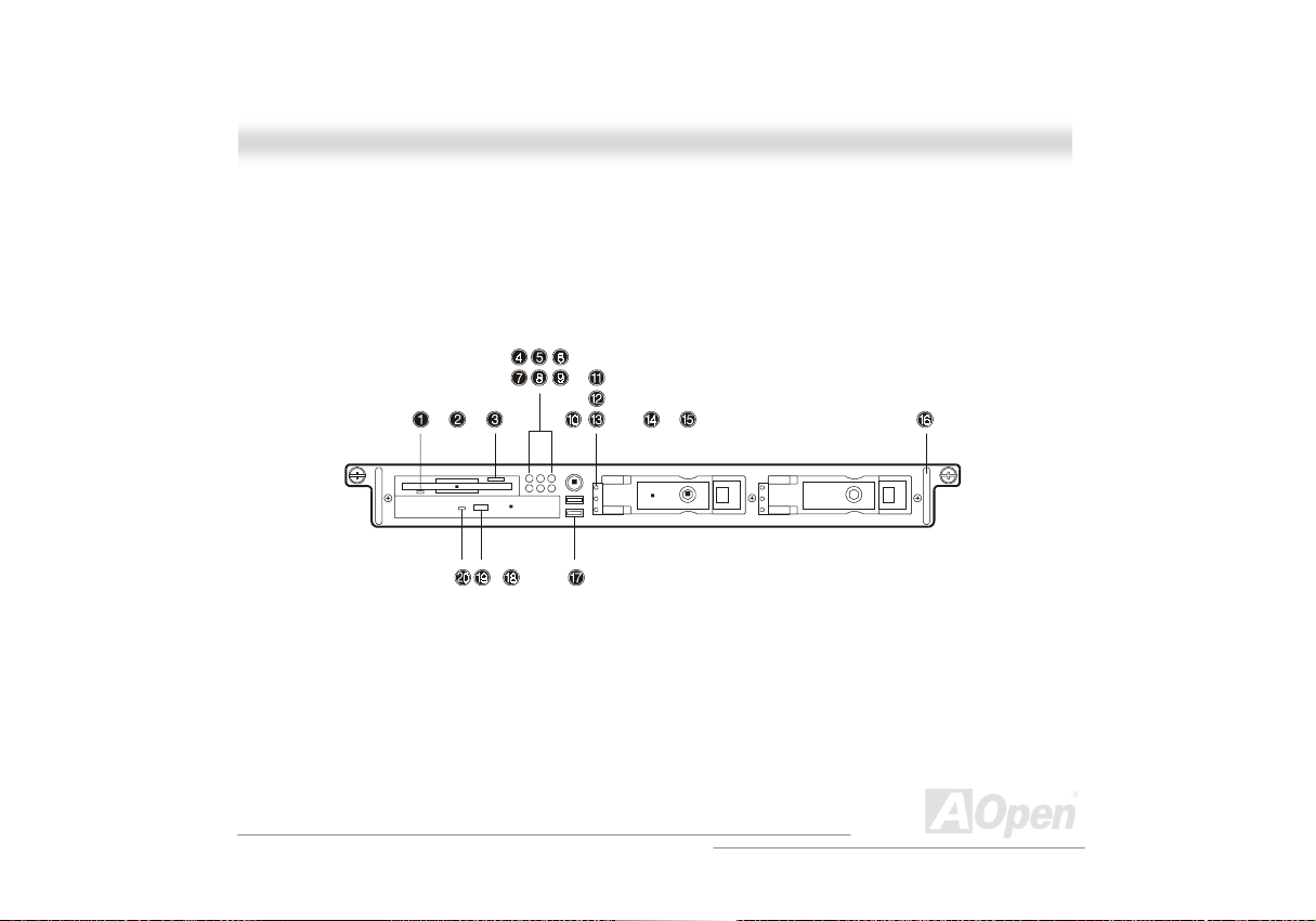
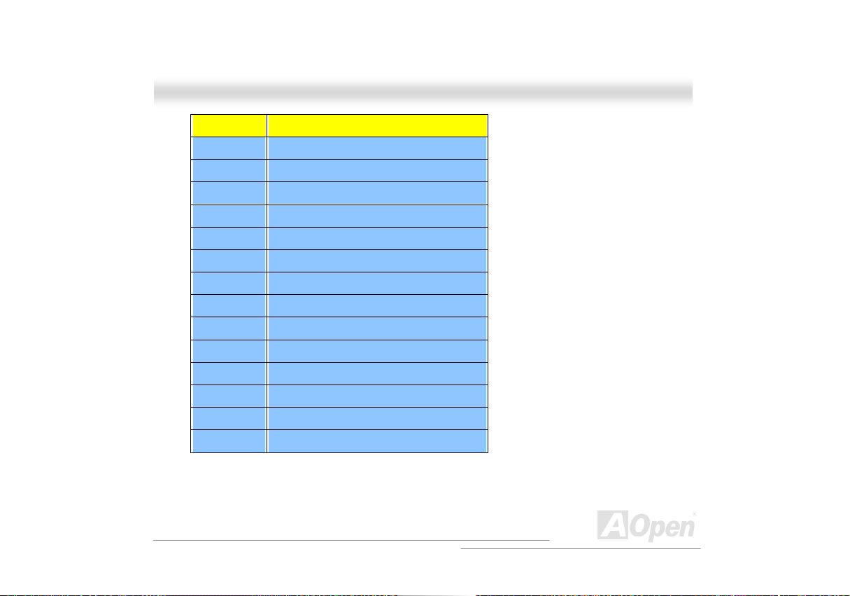
1.2.1 Front Panel
Additional duplicate keys can be found at the back of t he system.
Onnlliinnee MMaannuuaall
22
A
Open
O
Foorrttrreessss 99110000
F
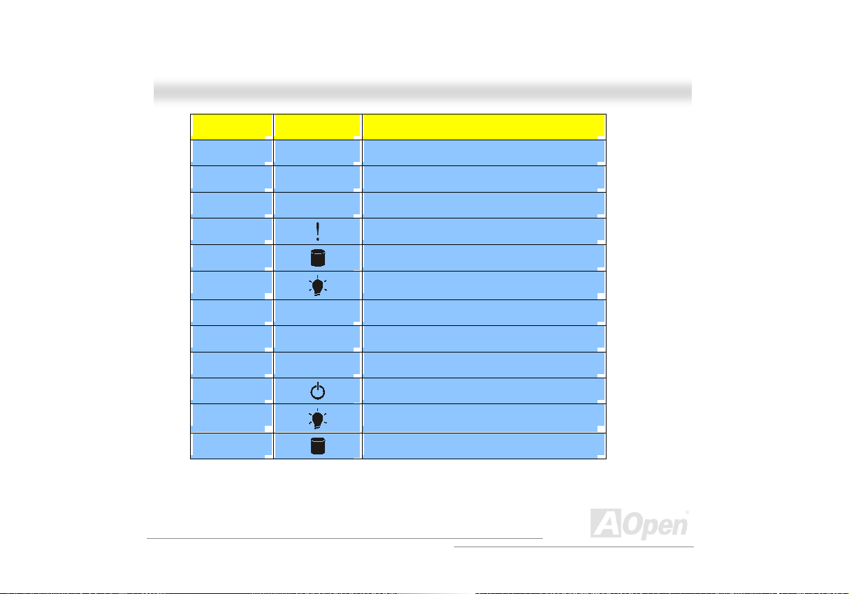
No. Icon Item
1 Slim type FDD LED
2 Slim type FDD
3 Slim type floppy disk eject button
4
5
6
7 LAN2 access LED
8 LAN1 access LED
9 Reserved
10
11
12
Event LED
HDD access LED
Power LED
Power switch
HDD power LED
HDD activity LED
Onnlliinnee MMaannuuaall
23
A
Open

O
Foorrttrreessss 99110000
F
13
14 Drive trays
15 Drive tray lock
16 Metal handle
17 USB ports (2 ports)
18 Slim type CD-ROM drive emergency ej ect hole
19 Slim type CD-ROM drive eject butt on
20 Slim type CD-ROM drive LED
HDD error LED
Onnlliinnee MMaannuuaall
24
A
Open
O
Foorrttrreessss 99110000
F
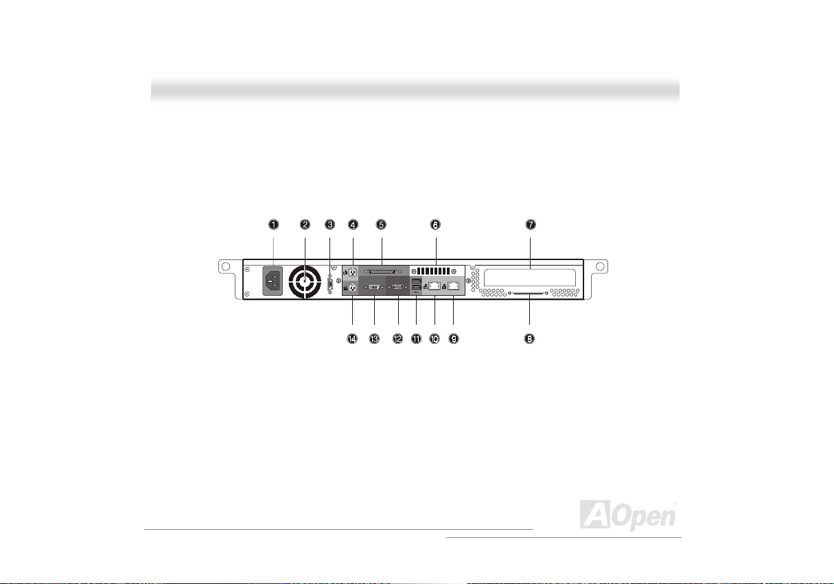
1.2.2 Real Panel
Onnlliinnee MMaannuuaall
25
A
Open
O
Foorrttrreessss 99110000
F
No. Item
1 Power supply
2 Power supply fan
3 Serial port 2
4 PS/2 mouse port
5 *Parallel Port (Optional)
6 Ventilation
7 Add-on card bracket
8 Very high density SCSI connector
9 LAN 2 RJ-45 port
10 LAN 1 RJ-45 port
11 USB ports
12 VGA port
13 Serial port 1
14 PS/2 keyboard port
* If you system without a parallel port, it will be changed to a ventilation of fan.
Onnlliinnee MMaannuuaall
26
A
Open
O
Foorrttrreessss 99110000
F
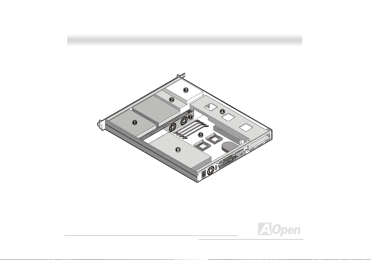
1.2.3 Internal Component
Onnlliinnee MMaannuuaall
27
A
Open

O
Foorrttrreessss 99110000
F
No. Item
1 Hot-swap SCSI HDD trays
2 Slim type CD-ROM drive
3 Slim type FDD
4 Metal bracket/Expansion card sl ot
5 DX3R-1U Motherboard
6 Power supply
7 Housing fan
Onnlliinnee MMaannuuaall
28
A
Open
O
8
Foorrttrreessss 99110000
F
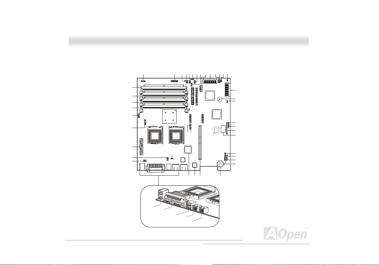
1.2.4 Motherboard Layout
DM4
DM3
DM2
DM1
CN1
CN8
CN3
CN13
CN5
CN7
CN6
CPU1 CPU2
CN4
CN10
CN15CN18CN19CN23
U10
JP10
U20
CN14
CN16
CN17
Onnlliinnee MMaannuuaall
CN28CN32
CN20
CN26
CN21
CN27
JP5
CN22
CN31
CN24
CN25
P2
U21
U32
CN30
U85
U92
U93
JP6
CN41
CN33
CN34
CN35/CN3
BU1
JP8
JP9
CN46
CN39
U99
CN37
CN43
CN42
CN36
BTI
A
29
Open

O
Foorrttrreessss 99110000
F
Item Description
BT1 Battery
BU1 Buzzer
CN1/CN6/CN36 IPMI connector
CN2 ITP port
CN3 ATX power suppl y connector
CN4 Upper: PS/2 mouse connect or
Lower: PS/2 keyboard connector
CN5 Serial port connector
CN7 CPU1 thermal connector
CN8 CPU1 fan connector
CN10 Upper: Parallel port
Lower left: Serial port 1
Lower right: VGA port
Onnlliinnee MMaannuuaall
30
A
Open

O
Foorrttrreessss 99110000
F
CN13 Housing fan connector
CN14 UBS1 and USB2 connector
CN15 LED/Switchboard connector
CN16 LAN1 RJ45 jack
CN17 LAN2 RJ45 jack
CN18 NMI switch
CN21 Primary IDE connector
CN22/CN31 BMC DB connector
CN25 CPU2 thermal connecto r
CN26 LAN1/LAN2 status report connector
CN27 Slim type CD-ROM connector
CN30 USB connector
CN32 Wide SCSI c hannel B connector
CN33/CN34 External HDD LED connector
Onnlliinnee MMaannuuaall
31
A
Open

O
Foorrttrreessss 99110000
F
CN35/CN38 Wide SCSI c hannel A connector
CN37 WOL connector
CN39 Slim type FDD connector
CN42 I2C connector
CN43 IOCHRDY (For debugging)
CN45 BPL1 fail LED
CPU1 1st CPU socket
CPU2 2nd CPU socket
DM1 to DM4 DIMM slots
JP4 Power LED & Reset switc h connector
JP5 Event clear connector
JP6 SCSI term i nat or
1-2: Disabled
2-3: On
Onnlliinnee MMaannuuaall
32
A
Open

O
Foorrttrreessss 99110000
F
JP8 Password setting
1-2: Check password
2-3: Bypass password
JP9 Speaker connector
P2 64-bit/66MHz PCI slot
U10 Server Works LE north bridge chipset
U20 Intel 82559 LAN1 controller
U21 ATI Rage XL video chi pset
U32 Intel 82559 LAN2 controller
U66 Adaptec AIC-7899 chipset
U92 Server Works LE south bridge chips et
U93 BIOS chipset
U99 SMC 47B277 super I/O chipset
Onnlliinnee MMaannuuaall
33
A
Open

O
Foorrttrreessss 99110000
F
1.2.5 LED/Switchboard Connector (CN15)
Onnlliinnee MMaannuuaall
34
A
Open

O
Foorrttrreessss 99110000
F
11..33 OOppeenniinngg tthhee HHoouussiinngg PPaanneellss
Always observe the following ESD (Electrostatic Discharge) precautions before installing any
system com ponent :
1. Do not remove any system component from its packaging unless you are ready to install it.
2. Wear an antistatic strap before handling electronic c omponent. Antistatic straps are available
at most electroni c component stores.
DO NOT attempt the procedures in the following sections
unless you are confident of your capability to perform
them. Otherwise, ask a service technician for as sistance.
Onnlliinnee MMaannuuaall
35
A
Open

O
Foorrttrreessss 99110000
F
Onnlliinnee MMaannuuaall
1.3.1 Opening the housing panel
A micro switch is allocated on the housing panel. It helps indicate whether the panel is removed or
intact. To open front door:
1. Turn off the power to the system unit and unplug all c abl es.
2. Unlock two thumbscrews us i ng your fingers.
3. Gently pull back the housing panel and det ach.
36
A
Open

O
Foorrttrreessss 99110000
F
Onnlliinnee MMaannuuaall
1.3.2 Installing an expansion board
To i nstall an expansion board:
1. Open the housing panel. See “Opening the housi ng pane
2. Remo ve the metal bracket from the housing by removing two screws. Save the screws for
later use.
3. Gently pull out the metal bracket with the riser card from the motherboard.
l” on page 39 for more informat i on.
37
A
Open

O
Foorrttrreessss 99110000
F
4. Remove the expansion slot bracket. Save the screw for later use.
5. Insert the expansion card into the ri ser card.
6. Secure the expansion board to the metal bracket with a screw.
Onnlliinnee MMaannuuaall
38
A
Open

O
Foorrttrreessss 99110000
F
7. Reinstall the metal bracket with the riser card into the motherboard and secure it with two
screws.
8. Reinstall the housing panel.
Onnlliinnee MMaannuuaall
39
A
Open

O
Foorrttrreessss 99110000
F
11..44 HHoott--sswwaappppiinngg SSCCSSII SSCCAA HHDDDD
You can hot-swap (remove or replace) a HDD any time when it fails to operate (indicated by the
yellow LED).
Do not remove a HDD when active. This may cause undue
damage to the HDD.
Onnlliinnee MMaannuuaall
40
A
Open

O
Foorrttrreessss 99110000
F
Follow these steps to instal l a hot-swappable SCSI drive:
1. Unlock the drive tray with a hex key.
2. Use your finger to release the drive tray and t hen pul l i t out.
Onnlliinnee MMaannuuaall
41
A
Open

O
Foorrttrreessss 99110000
F
3. Place a hard disk on the tray. Secure it with four screws as shown below.
Onnlliinnee MMaannuuaall
42
A
Open

O
Foorrttrreessss 99110000
F
4. Insert the tray into the hot-swap cage with the lever st ill extended. Make s ure that the drive is
properly inserted before closing t he l ever.
5. Push the lever back until i t close into place.
Onnlliinnee MMaannuuaall
43
A
Open

O
Foorrttrreessss 99110000
F
11..55 IInnssttaalllliinngg && RReemmoovviinngg tthhee CCPPUU
The Pentium III comes in a FC-PGA (Flip-Chip Pin Grid A rray) 370-pi n package. The FC-PGA
package is designed for the new breed of sl eek, high performance, s mall form fact or P Cs.
Always observe the ESD precautions when installing or
removing a system component. Refer to the section
above.
Onnlliinnee MMaannuuaall
1.5.1 Installing a CPU
Follow the steps to install a CPU:
1. Remove the processor from its protective packaging.
2. Insert the new CPU into the CPU socket (a and b). Make sure that pin 1 (indicated by a
notched corner) of the CPU connec ts to hole 1 of the sock et.
Push down the socket lever to l ock the new CPU into the socket.
You need to install a terminator board into the CPU2 socket
if you only install one CPU (must be inst alled in the CPU1
socket). Also, change JP10 to “ON” if you inst all a term inator
board into the CPU2 socket .
44
A
Open

O
Foorrttrreessss 99110000
F
3. Attach one side of the f an/heatsink metal bracket to the CPU sock et (e) and then gently push
down the other side of the metal bracket (f) until it locks in place (g).
Onnlliinnee MMaannuuaall
45
A
Open

O
Foorrttrreessss 99110000
F
4. Connect the 3-pin and 2-pin fan /heats i nk cables to the motherboard. Refer to “Motherboard
Layout” on page 29 for the location of the fan/heatsink connect ors.
The heatsink becomes very hot when the system is on.
Never touch the heatsink with any metal or with your hand.
Onnlliinnee MMaannuuaall
46
A
Open

O
Foorrttrreessss 99110000
F
Onnlliinnee MMaannuuaall
1.5.2 Removing a CPU
Following these steps to remove a CPU:
1. Disconnect the 3-pin and 2-pin fan/heatsink cables from the system board.
2. Release the fan/heatsink metal bracket by pressing the hook (a). Unhook one side of the
fan/heatsink metal bracket (b) and gently lift i t before removing the other side (c and d).
3. Push the socket l ever down to release the lever (e) and then carefully rem ove the CPU (f)
47
A
Open

O
Foorrttrreessss 99110000
F
11..66 IInnssttaalllliinngg aanndd RReemmoovviinngg MMeemmoorryy MMoodduulleess
The four 168-pin sockets on board support SDRAM type DIMMs. You may install 128, 256, 512 or
1024MB (single and double density) DIMM for a maximum of 4GB system memory.
The SDRAM should work under 3.3V only; 5V memory
devices are not supported.
This motherboard supports PC-100 and PC-133 SDRAM. However, they cannot be used at the
same time in the system.
Do not use both PC-100 and PC-133 SDRAM together. This
might cause your system to malfunction. For a list of
qualified DIMM vendors, please cont act your reseller.
Each of the DIMM sockets is independent from the ot hers. This independence allows you to inst al l
DIMMs with different capacities to form different configuration.
Onnlliinnee MMaannuuaall
48
A
Open

O
Foorrttrreessss 99110000
F
Onnlliinnee MMaannuuaall
1.6.1 Installing a DIMM
To i nstall a DIMM, align it to an empty slot and press it i n unt i l the holding clips secure t he DIMM in
place.
The DIMM socket is slotted to ensure proper installation. If
you slip in a DIMM but it does not completely fit, you may
insert it the wrong way. Reverse the orientation of the DIMM.
49
A
Open

O
Foorrttrreessss 99110000
F
Onnlliinnee MMaannuuaall
1.6.2 Removing a DIMM
To remove a DIMM, press the holding cli ps on both sides of the soc ket outward to release the
DIMM.
Place your forefingers on the top of the DIMM before you
press the holding clips to gently disengage t he DIMM from
the socket.
50
A
Open

O
Foorrttrreessss 99110000
F
Onnlliinnee MMaannuuaall
1.6.2 Reconfiguring the system
The system automatically detects the amount of memory installed. Run BIOS Setup to view the
new value for total system memory and make a note of it.
51
A
Open

O
Foorrttrreessss 99110000
F
11..77 SSeerrvveerr RRaacckk IInnssttaallllaattiioonn ((OOppttiioonnaall))
Onnlliinnee MMaannuuaall
1.7.1 Vertical mounting hole pattern
The four vertical rails of a rac k contain mounting holes arranged i n a manner shown in this figure.
4th U
3rd U
2nd U
1st U
3rd
2nd
1st
52
A
Open

O
Foorrttrreessss 99110000
F
The system occupies 1U in the rack. Count the U posi tions and hole numbers from the bottom up.
The distance from the center of two holes with closer spacing to the center of the next pair is
equivalent to 1U.
When installing components, you must start your measurement from the center of the two holes
with closer spacing. Otherwise, the screw holes on the component may not match with t hose on
the rack.
The unit of measurement used in this document is “U”
(1U=1.75 inches or 44.45mm). The total sum of the height of
all components in the rack measured in “U” cannot exceed
the height of the rack. For more information, please refer to
the rack’s documentat i on.
Onnlliinnee MMaannuuaall
53
A
Open

O
Foorrttrreessss 99110000
F
Onnlliinnee MMaannuuaall
1.7.2 Installing cage nuts
To i nstall the system i nto the rack:
The rails allow the system to slide in and out of the rackmount f or maintenance purposes. Follow
these steps to install the mounting rails:
1. E xtend the component rai l (a) from the mounting rail (b) until the component rail rel ease latch
clicks. Hold down the latch and slip the component rail out of the mounting rail. Do the same
thing to the other mounting rai l .
Each mounting rail consists of a fixed outer piece that
screws onto the mounting bracket and an inner sliding piece
controlled by a steel ball gear movement. This inner sliding
piece is not detachable.
54
A
Open

O
Foorrttrreessss 99110000
F
2. Put the component rails aside.
Onnlliinnee MMaannuuaall
55
A
Open

O
Foorrttrreessss 99110000
F
3. Attach the mounting brackets to the mounting rails. The mounting brackets consist of two
metal bars to be attached on both ends of the mounting rail s.
a. Attach the mounting bracket to the front end of the mounting rail and align the screw
holes.
b. Sec ure it with three M4x8L screws with nut and washer as shown below. Slide and
adjust the inner piece of the mounting rail to gain access to the screw holes. The
position of the mounti ng bracket on this end is fi xed.
Look for an imprint that says front or rear on the mounting
bracket. Install the mounting bracket on t he appropriate si de;
otherwise, it will not fit correctly into the rack.
Onnlliinnee MMaannuuaall
56
A
Open

O
Foorrttrreessss 99110000
F
c. Extend the inner sliding piece of the mounting rail until you can see the screw holes on
the other end. Attach the mounting bracket to the rear end and secure it with two
screws. The mounting rail in t hi s end is adjustable.
Onnlliinnee MMaannuuaall
57
A
Open

O
Foorrttrreessss 99110000
F
4. Attach the mounti ng brackets and the cable carrier to the rack with nine M6 screws.
a. Install the left mounti ng bracket first using f our M6 s crews.
The system occupies 1U. Count the U positions and hole
numbers from the bottom up. Secure the mounting bracket
on the 1
Make sure that both of the mounting brackets are at the
same level. Take note of the vertical rail hole pattern. See
“Vertical mounting hole pattern
st
and 2nd holes of the 1st U using four M6 screws.
” on page 52
Onnlliinnee MMaannuuaall
58
A
Open

O
Foorrttrreessss 99110000
F
Onnlliinnee MMaannuuaall
b. I nstall the right mounting bracket with the cable carrier using five M6 screws. The cable
carrier is installed on t he rear as shown below.
1st U
3rd
2nd
1st
&&&&
9999
8888
3/
3/
3/3/
1st
The cable carrier allows you to tie-wrap all cables to and
from the server. As you slide the system in and out of the
rack, the cable carrier collapses and extends, keeping the
cables untangled and attached t o t he system.
59
A
Open

O
Foorrttrreessss 99110000
F
5. Secure the front panel to the s ys tem with three M3 screws.
6. Attach the component rails to the system with eight M4x5L screws.
Onnlliinnee MMaannuuaall
60
A
Open

O
Foorrttrreessss 99110000
F
7. Extend the inner sliding piece of the mounting bracket.
Onnlliinnee MMaannuuaall
61
A
Open

O
Foorrttrreessss 99110000
F
8. Slide the system i nto the rack.
Onnlliinnee MMaannuuaall
62
A
Open

O
Foorrttrreessss 99110000
F
9. Attach the cable carrier arm bracket to the rear of the system using two #6-32 screws. See the
figure shown as below.
10. Attaching cable carrier to the cable carrier arm bracket using three #6-32 screws.
Onnlliinnee MMaannuuaall
63
A
Open

O
Foorrttrreessss 99110000
F
11. Pull out the system to extend the cable c arrier. Bundle all cables to the c able carrier with t he
cable straps. Route all cables from the cable carrier to the cable managem ent bracket located
on the rear of the rack.
12. Install two cage nuts (see page 54
) and secure the system t o the rack using two M6 screws.
Onnlliinnee MMaannuuaall
64
A
Open

O
Foorrttrreessss 99110000
F
CChhaapptteerr 22 BBIIOOSS SSeettuupp UUttiilliittyy
Most of system had already configured by the manufacturer or the dealer. There is no need to run
BIOS setup program when start i ng t he computer unless you get a run s etup program message.
The setup program loads confi guration values into the battery-bac ked nonvolatile memory c al l ed
CMOS RAM. This memory area is not part of the system RAM.
If you repeatedly receive Run Setup messages, the battery
may be bad. In this case, the system cannot retain
configuration values in CMOS. Ask a qualified technician for
assistance.
The system will reboot immediately af t er you exit Setup.
Onnlliinnee MMaannuuaall
65
A
Open

O
Foorrttrreessss 99110000
F
22..11 EEnntteerriinngg SSeettuupp
To enter Setup, press the DELETE key.
You must press DELETE while the system is booting. This
key does not work during any other time.
The Setup Utility Main Menu appears:
The system supports two BIOS Ut ility levels: Basic and Advanced.
If you are an advanced user, you may want to check the detail ed configuration of your system.
Onnlliinnee MMaannuuaall
66
A
Open

O
Foorrttrreessss 99110000
F
Detailed system configurations are contained in the Advanced Level. To view the Advanced Level,
press
Use the arrow keys
Use
more than one page available.
Use
Press
.
The asterisk (*) mark indicates that the parameter appears
only when you are in the Advanced Level.
The parameters on the screens show default values.
These values may not be the same as those in your
system.
The grayed items on the screens have fixed settings and
are not user-configurable.
and to move around the Setup Utility screen.
to move to the next page or to return to the previous page if the setup s creen has
, , “+” or “-” to select the options if they are available.
to return to the Main menu.
Onnlliinnee MMaannuuaall
67
A
Open

O
Foorrttrreessss 99110000
F
22..22 SSyysstteemm IInnffoorrmmaattiioonn
The following screen appears if you selec t System Information from the Main menu:
The System Information menu shows the current bas i c configuration of your syst em.
Onnlliinnee MMaannuuaall
68
A
Open

O
Foorrttrreessss 99110000
F
The sections below explain the parameters.
Onnlliinnee MMaannuuaall
2.2.1 Processor
The Processor parameter s pecifies the type of processor currently installed in your system. The
system supports I ntel Pentium II and P entium III processors.
2.2.2 Processor Speed
The Processor Speed parameter specifies the speed of the processor currently inst al l ed i n your
system.
2.2.3 CPU/SDRAM BUS Frequency
This parameter specif i es the currently FSB (Front Side B us) frequency of the CPU/SDRAM.
2.2.4 Level 1 Cache
This parameter specifies the first-level or t he i nternal fast access ed memory (i.e., t he memory
integrated into the CPU) size, and whether it is enabled or disabled.
69
A
Open

O
Foorrttrreessss 99110000
F
Onnlliinnee MMaannuuaall
2.2.5 Level 2 Cache
This parameter specifies the second-level cac he memory size that c omes with the CPU. The
available cache size is 256/ 512 KB.
2.2.6 Diskette Drive A
This parameter specif i es the system’s current di skette drive A settings.
2.2.7 Diskette Drive B
This parameter specif i es the system’s current di skette drive B settings.
2.2.8 IDE Primary Channel Master
This parameter specif i es the current configuration of the IDE device connected to the master port
of the primary IDE channel .
2.2.9 IDE Primary Channel Slave
This parameter specif i es the current configuration of the IDE device connected to the slave port of
the primary IDE channel.
70
A
Open

O
Foorrttrreessss 99110000
F
Onnlliinnee MMaannuuaall
2.2.10 Total Memory
This parameter specif i es the total amount of onboard memory. The memory size is automati cally
detected by BIOS during the PO S T. If you install additional memory, the system automatical l y
adjusts this parameter to display the new memory size.
1st Bank/2nd Bank/3rd Bank
The 1st Bank, 2nd Bank, and 3rd Bank parameters indicat e the type and size of DRAM installed in
DIMM sockets 1, 2, and 3 respectively. The “None” setting indicates that there is no DRA M
installed. For the locat i on of the DIMM sockets, refer to section 2.3 or 2.4.
2.2.11 1st/2nd/3rd Bank
Type and Size of DRAM installed in DIMM socket 1, 2, 3 and 4 res pectively. The “None” setting
indicates that there is no DRAM installed.
2.2.12 Serial Port 1
This parameter shows the serial port 1 address and IRQ setting.
71
A
Open

O
Foorrttrreessss 99110000
F
Onnlliinnee MMaannuuaall
2.2.13 Serial Port 2
This parameter shows the serial port 2 address and IRQ setting.
2.2.14 Parallel Port
This parameter shows the parallel port address and IRQ setting.
2.2.15 PS/2 Mouse
The BIOS utility automatically det ec ts if there is a pointing device connected t o your s ystem. If
there is, this param eter displays the “Installed” setting. Otherwise, this is set to “None”.
72
A
Open

O
Foorrttrreessss 99110000
F
22..33 PPrroodduucctt IInnffoorrmmaattiioonn
The Product Informati on contains the general data about the s ys tem, such as the produc t name,
serial number, BIOS version, etc. Thi s information is nec essary for troubleshooting (may be
required when asking for technical s upport ).
The following shows how the Product Informat i on screen appears:
Onnlliinnee MMaannuuaall
73
A
Open

O
Foorrttrreessss 99110000
F
2.3.1 Product Name
This parameter specif i es the official name of t he system.
2.3.2 System S/N
This parameter specif i es the system’s serial number.
2.3.3 Main Board ID
This parameter specif i es the motherboard’s identification number.
2.3.4 Main Board S/N
This parameter specif i es the motherboard’s serial number.
2.3.5 System BIOS Version
This parameter specifies the version of the BIOS utility.
Onnlliinnee MMaannuuaall
74
A
Open

O
Foorrttrreessss 99110000
F
2.3.6 SMBIOS Version
This parameter specif i es the version of the SMBIOS version.
Onnlliinnee MMaannuuaall
75
A
Open

O
Foorrttrreessss 99110000
F
22..44 DDiisskk DDrriivveess
Select Disk Drives to input configuration values for disk drives.
The following screen shows the Disk Drives menu:
Onnlliinnee MMaannuuaall
76
A
Open

O
Foorrttrreessss 99110000
F
Onnlliinnee MMaannuuaall
2.4.1 Floppy Drives
To enter the configuration value for the f i rst floppy drive, highlight the Fl oppy Dri ve A parameter.
Press
Drive A/Drive B
None
360KB 5.25"
1.2MB 5.25"
720KB 3.5"
1.44MB 3.5"
2.88MB 3.5"
Follow the same procedure to confi gure floppy drive B. Choose “None” if you do not have a second
floppy drive.
or
key to view the options and selec t the appropriate value.
,
These items selec t the floppy drive type. The available settings and
types supported by the motherboard are l i sted to the left.
2.4.2 IDE Drives
To configure the IDE drives connected to your system, s el ect the parameter that repres ents the
channel and port where the desired hard disk to c onfigure is connected. The options are:
IDE Primary/Secondary Channel Master
77
A
Open

O
Foorrttrreessss 99110000
F
This option lets you confi gure the hard disk drive connected to t he master port of IDE channel 1/ 2.
IDE Primary/Secondary Channel Slave
This option lets you confi gure the hard disk drive connected to t he slave port of IDE channel 1/2.
The following screen appears if you select any of the IDE Drive parameters:
Onnlliinnee MMaannuuaall
78
A
Open

O
Foorrttrreessss 99110000
F
Onnlliinnee MMaannuuaall
2.4.3 Device Detection Mode
Device Detection
Mode
Auto (Default)
User
None
If you select “Manual”, you need to fill in all remaining fiel d, such as Cylinder,
Head, and Sector on this selected item. If the item “Auto” is selected, the
items will remain “0”. And when the system boot up, system will detect the
hard disk and configure it automatically. “None” means there is no device in
the channel.
Device Type
This parameter shows which type of IDE dri ve c urrently used.
Cylinder
This parameter specif i es the number of cylinders of your hard di sk, and is automati cally set
depending on your Type parameter setting.
Head
This parameter specif i es the number of heads of your hard disk, and is automatically set
depending on your Type parameter setting.
79
A
Open

O
Foorrttrreessss 99110000
F
Onnlliinnee MMaannuuaall
Sector
This parameter specif i es the number of sectors of your hard disk, and is automatically set
depending on your Type parameter setting.
Size
This parameter specif i es the size of your hard disk, i n MB.
2.4.4 Hard Disk LBA Mode
Hard Disk Block
Mode
Auto (Default)
Disabled
This function enhances disk performance depending on t he hard disk in
use. If you set this parameter to “Auto”, the BIOS utility aut omatically
detects if the installed hard disk drive supports the Block Mode function.
If supported, it allows data transfer in blocks (multipl e sectors) at a rate
of 256 bytes per cycle. To disregard the feature, change the setting to
“Disable”.
80
A
Open

O
Foorrttrreessss 99110000
F
22..55 OOnnbbooaarrdd PPeerriipphheerraallss
The Onboard Peripherals Configuration allows you to conf igure the onboard communication ports
and the onboard devices. Select i ng this option displays the following screen:
Onnlliinnee MMaannuuaall
81
A
Open

O
Foorrttrreessss 99110000
F
This page is the lower half of Onboard Peripherals submenu.
Onnlliinnee MMaannuuaall
82
A
Open

O
Foorrttrreessss 99110000
F
2.5.1 Serial Ports 1 and 2
Serial Port 1 & 2
Enabled (Default)
Disabled
2.5.1.1 Base Address
Base Address
Serial Port 1:
3F8h (Default)
3E8h
2E8h
Serial Port 2:
2F8h (Default)
2E8h
3E8h
Onnlliinnee MMaannuuaall
These parameters allow you to enable or disable serial
ports 1 and 2.
This item allows you to assign address and interrupt for the
board serial port.
83
A
Open

O
Foorrttrreessss 99110000
F
2.5.1.2 IRQ
IRQ
Serial Port 1:
4 (Default), 11
Serial Port 2:
3 (Default), 10
The Base Address and IRQ parameters for each port are
configurable only if the port is enabled.
2.5.2 Parallel Port
Parallel Port
Enabled (Default)
Disabled
Onnlliinnee MMaannuuaall
This function lets you assign an interrupt for serial ports 1
and 2. The options for serial ports 1 are IRQ 4 and 11. The
options for serial port 2 are IRQ 3 and 10.
This parameter allows you to enable or dis abl e the parallel
port.
84
A
Open

O
Foorrttrreessss 99110000
F
2.5.2.1 Base Address
Base Address
378h (Default)
3BCh
278h
2.5.2.2 IRQ
IRQ
7 (Default), 5
The Base Address and IRQ parameters are configurable only if
Parallel Port is enabled.
If you install an add-on card that has a parallel port whose
address conflicts with the onboard parallel port, a warning
appears on the screen.
Check the parallel port address of the add-on card and change
the address to one that does not conflict.
Onnlliinnee MMaannuuaall
This item allows you to assign address and interrupt for the
board serial port.
This function lets you assign an interrupt for the parallel
port. The options are IRQ 5 and 7.
85
A
Open

O
Foorrttrreessss 99110000
F
2.5.2.3 Operation Mode
Operation Mode
EPP (Default)
Bi-Directional
Standard
ECP
Setting Function
Standard Parallel Port (Standard) A l l ows normal speed one-way operation
Bi-directional Parallel Port
(Bi-directional)
Enhanced Parallel Port (EPP) Allows bi-directional parallel port operation at
Extended Capabilities Port (ECP) Allows parallel port to operate in
This item lets you set the parallel port mode. The mode
options are Standard, Bi-directional, EPP (Enhanced
Parallel Port) and ECP (Extended Parall el Port).
Allows normal speed operation in a two-way
mode
maximum speed
bi-directional mode and at a speed higher
than the maximum data transfer rate
Onnlliinnee MMaannuuaall
86
A
Open

O
Foorrttrreessss 99110000
F
2.5.2.4 ECP DMA Channel
ECP Mode Use DMA
3
1 (Default)
Onnlliinnee MMaannuuaall
This item becomes active only if you select Extended
Capabilities Port (ECP) as the operation mode. It allows you
to assign DMA channel 1 or DMA channel 3 for the ECP
parallel port function (as required i n Windows 95).
87
A
Open

O
Foorrttrreessss 99110000
F
2.5.3 Onboard Device Settings
The Onboard Device Settings m enu al l ows you t o configure the onboard communi cation ports and
the onboard devices. Select i ng this option from the Onboard P eri pheral s menu displays the
following screen:
Onnlliinnee MMaannuuaall
88
A
Open

O
Foorrttrreessss 99110000
F
2.5.3.1 Floppy Disk Controll er
Floppy Disk
Controller
Enabled (Default)
Disabled
2.5.3.2 IDE Controller
IDE Controller
Both (Default)
Primary
Disabled
This parameter lets you enable or di sable the onboard floppy
disk controller.
Set this parameter t o “Primary” to enable only the primary IDE
controller; “Both” to enable bot h pri mary and secondary IDE
controllers; or “Disabled” to disable all IDE controll ers.
Onnlliinnee MMaannuuaall
89
A
Open

O
Foorrttrreessss 99110000
F
2.5.3.3 PS/2 Mouse Controller
PS/2 Mouse
Controller
Enabled (Default)
Disabled
2.5.3.4 USB Host Control l er
USB Host
Controller
Enabled (Default)
Disabled
2.5.3.5 USB Legacy Mode
USB Legacy Mode
Enabled
Disabled (Default)
This parameter enables or disabl es the onboard PS/2 mouse
controller.
This parameter lets you enable or di sable the USB controller on
board. When enabled, it activates the USB function of the
system. When disabled, it deact i vates the function.
This parameter lets you enable or di sable the USB controller on
board. When enabled, it activates the USB function of the
system. When disabled, it deact i vates the function.
Onnlliinnee MMaannuuaall
90
A
Open

O
Foorrttrreessss 99110000
F
2.5.3.6 Onboard Ethernet Chip 2
On-board
Ethernet Chip 2
Enabled
Disabled (Default)
This parameter allows you to enable or dis abl e the function of
onboard Ethernet controller 2.
Onnlliinnee MMaannuuaall
91
A
Open

O
Foorrttrreessss 99110000
F
22..66 PPoowweerr MMaannaaggeemmeenntt
The Power Management menu allows you to configure the system power-management feature.
The following screen shows the Power Management param et ers and their default settings:
Onnlliinnee MMaannuuaall
92
A
Open

O
Foorrttrreessss 99110000
F
A parameter with an asterisk (*) mark indicates that the
parameter appears only when you are using in the Advanced
Level. See “Entering Setup” on Page
2.6.1 Power Management Mode
Power
Management
Mode
Enabled (Default)
Disabled
2.6.1.1 IDE Hard Disk Standby Tim er
IDE Hard Disk
Standby Timer
Off (Default)
1 to 15min
This parameter allows you to reduce power consumption.
When this parameter is s et to “Enabled”, you can configure the
IDE hard disk and system timers. Setting it to “Disabled”
deactivates the power-managem ent feature and its tim ers.
This parameter allows the hard disk to enter standby mode after
inactivity of 1 to 15 minutes, depending on your setting. When
you access the hard disk again, allow 3 to 5 seconds (depending
on the hard disk) for the disk to return to normal speed. Set this
parameter to “Off” if your hard disk does not support this
function.
Onnlliinnee MMaannuuaall
93
A
Open

O
Foorrttrreessss 99110000
F
2.6.1.2 System Sleep Timer
System Sleep
Timer
Off (Default)
120, 110, 100…20,
15, 10, 5, 2min
2.6.1.3 Sleep Mode
Sleep Mode
Standby
Suspend (Default)
Onnlliinnee MMaannuuaall
This parameter sets the system to the lowest power-saving
mode after a specif i ed peri od of inactivity. Any keyboard or
mouse action or any acti vi ty detected from the IRQ channels
resumes system operation.
This parameter lets you specify the power-saving mode that the
system will enter after a specified period of inactivity. The options
are “Standby” and “Suspend” modes. This parameter becomes
configurable only if the System Sleep Timer is enabled. Any
keyboard or mouse action, or any enabled monitored activi ties
occurring through the IRQ channels resume system operati on.
94
A
Open

O
Foorrttrreessss 99110000
F
Onnlliinnee MMaannuuaall
2.6.2 Power Switch < 4 sec.
Power Switch < 4
Sec.
Suspend
Power Off (Default)
When set to ”Power Off”, the system automatically turns off
when the power switch is pressed for less than 4 seconds. When
set to ”Suspend”, the system enters the suspend mode when
pressed for less than 4 seconds.
2.6.3 System Wake-up Event
The system wake-up event allows the s ys tem to resume operation when the modem ring indicator
is enabled.
2.6.3.1 Modem Ring Indicator
Modem Ring
Indicator
Enabled
Disabled (Default)
When “Enabled” any fax/modem activity wakes up the system
from suspend mode. The default setting is “Disabled”.
95
A
Open

O
Foorrttrreessss 99110000
F
2.6.3.2 PCI Power M anagem ent
PCI Power
Management
Enabled (Default)
Disabled
2.6.3.3 RTC Alarm
RTC Alarm
Enabled
Disabled (Default)
Resume Day
Resume Day
1 to 31
This item allows you to enable or disable the PCI power
management funct i on.
This item allows you to set a certain time on a certain day t o
wake-up the system from suspend mode.
Onnlliinnee MMaannuuaall
This item is displayed when you enable the “RTC Timer” option.
Here you can specify what date you want to wake up the system.
For example, setting to 15, the system will wake up on the 15th
day of every month.
96
A
Open

O
Foorrttrreessss 99110000
F
Resume Time
Resume Time
hh:mm:ss
2.6.3.4 Restart On AC/Power Failure
Restart On
AC/Power Failure
Enabled
Disabled (Default)
Pre-State
When “Enabled”, the system automatically turns on when the
power comes back. When “Disabled” the system turns off and
does not turn on when the power comes back. When set to
“Pre-State”, the system maintains the last power state when the
power comes back.
Onnlliinnee MMaannuuaall
This item is displayed when you enable the RTC Wake Up Timer
option. Here you can specify what time you want to wake up the
system.
97
A
Open

O
Foorrttrreessss 99110000
F
22..77 BBoooott OOppttiioonnss
This option allows you to specify your preferred setting for boot up.
The following screen appears if you selec t Boot Options from t he Basic Configuration menu:
Onnlliinnee MMaannuuaall
98
A
Open

O
Foorrttrreessss 99110000
F
2.7.1 Boot Sequence
This parameter allows you to specify the boot search sequence duri ng POST.
•
1st. The system checks this drive first.
•
2nd. The system then checks this drive if it can not boot from the 1st specified
drive.
•
3rd. If the 1st and 2nd searches fail then it boots from this drive.
•
4th. If the 1st, 2nd, and 3rd searches fail then it boots from this drive.
BIOS will display an error message if the drive(s) specified is not bootable.
2.7.2 Primary Display Adapter
Primary Display
Adapter
Auto
Onboard (Default)
This parameter lets you activate the onboard video controller as
your primary display adapter, or automatically disable it once
BIOS detects that there is a video card install ed i n your system.
Onnlliinnee MMaannuuaall
99
A
Open

O
Foorrttrreessss 99110000
F
2.7.3 Fast Boot
Fast Boot
Auto (Default)
Disabled
2.7.4 Silent Boot
Silent Boot
Enabled (Default)
Disabled
Onnlliinnee MMaannuuaall
This parameter allows the system to boot faster by s kipping
some POST routines .
This parameter enables or disables the Silent Boot function.
When set to ”Enabled”, BIOS is in graphical mode and displays
only an identification logo during POST and while booting. After
booting the screen displays the operating system prompt (such
as DOS) or logo (such as Windows 95). If any error occurs while
booting, the system automatically switches to the text mode.
Even if your setting is ”Enabled”, you may also switch to the text
mode while booting by pressing
DELETE key to enter setup” message on the screen.
When set to “Disabled”, BIOS is in t he conventional text mode
where you see the system initial i zation details on the screen.
when you see the “Press
100
A
Open
 Loading...