

Page 1
SIMPLY CLEVER
ŠKODA Yeti
Owner's Manual
Page 2

Layout of this Owner's Manual (explanations)
This Owner's Manual has been systematically designed to make it easy for you to
search for and obtain the information you require.
Chapters, table of contents and subject index
The text of the Owner's manual is divided into relatively short sections which are
combined into easy-to-read chapters. The chapter you are reading at any particular
moment is always specified on the bottom right of the page.
The Table of contents is arranged according to the chapters and the detailed Sub-
ject index at the end of the Owner's Manual helps you to rapidly find the information you are looking for.
Direction indications
All direction indications such as “left”, “right”, “front”, “rear” relate to the direction of
travel of the vehicle.
Units of measurement
All values are expressed in metric units.
Explanation of symbols
Denotes a reference to a section with important information and safety
advice in a chapter.
Denotes the end of a section.
Denotes the continuation of a section on the next page.
Indicates situations where the vehicle must be stopped as soon as possi-
ble.
® Denotes a registered trademark.
Indicates the texts displayed in the MAXI DOT screen.
Indicates the texts shown in the segment display.
Display
In this owner's manual, the screen on the MAXI DOT display is used as the display
illustration, provided it is not otherwise stated.
Notes
WARNING
The most important notes are marked with the heading WARNING. These
WARNING notes draw your attention to a serious risk of accident or injury.
CAUTION
A Caution note draws your attention to the possibility of damage to your vehicle
(e.g. damage to gearbox), or points out general risks of an accident.
For the sake of the environment
An Environmental note draws your attention to environmental protection aspects.
This is where you will, for example, find tips aimed at reducing your fuel consumption.
Note
A normal Note draws your attention to important information about the operation
of your vehicle.
Page 3
Documentation of vehicle delivery
Date of delivery/first registrationa) (VIN)
Vehicle identification number
I confirm that I have taken delivery of the specified vehicle in good condition, have received information on how to operate it correctly, and have
had the terms of the warranty explained to me.
a)
(whichever comes first).
stamp and signature of the seller
ŠKODA partner
Signature of the customer
ŠKODA extended warranty
Limitations of the ŠKODA extended warranty
Years:
or
km:
a)
(whichever comes first).
Stamp of ŠKODA Partner
Valid from:
a)
Page 4

Preface
You have opted for a ŠKODA – our sincere thanks for your confidence in us.
You have received a vehicle with the latest technology and range of amenities. Please read this Owner's
Manual carefully, because the operation in accordance with these instructions is a prerequisite for proper use
of the vehicle.
If you have any questions about your vehicle, please contact a ŠKODA Partner.
We hope you enjoy driving your ŠKODA, and wish you a pleasant journey at all times.
Your ŠKODA AUTO a.s. (hereinafter referred to only as ŠKODA or manufacturer)
Page 5

Terms used
The on-board literature contains the following terms relating to the service work
for your vehicle.
“Specialist garage” - a company that carries out specialist service tasks for
›
ŠKODA vehicles. A specialist can be a ŠKODA Partner, a ŠKODA Service Partner,
or an independent workshop.
“ŠKODA Service Partner” - A workshop that has been contractually authorized
›
by the manufacturer ŠKODA AUTO a.s. or its sales partner to perform service
tasks on ŠKODA vehicles and to sell ŠKODA Genuine Parts.
“ŠKODA Partner” - A company that has been authorized by the manufacturer
›
ŠKODA AUTO a.s. or its sales partner to sell new ŠKODA vehicles and, when applicable, to service them using ŠKODA Genuine Parts and to sell ŠKODA Genuine
Parts.
Owner's Manual
These operating instructions apply to all body variants of the vehicle and to all
related models.
This Owner's Manual describes all possible equipment variants without identifying them as special equipment, model variants or market-dependent equipment.
Consequently, your vehicle does not need to contain all of the equipment com-
ponents described in this Owner's Manual.
The level of equipment in your vehicle refers to your purchase contract for the vehicle. More information is available from the ŠKODA Partner from whom you
bought the vehicle.
The illustrations can differ in minor details from your vehicle; they are only intended for general information.
Page 6

Table of Contents
Materials defect liability and ŠKODA warranty for
new cars 5
Mobility warranty and ŠKODA extended
warranty
Abbreviations
Using the system
Cockpit
Overview
Instruments and Indicator Lights 10
Instrument cluster
Warning lights
Information system 23
Driver information system
Multifunction display (MFD) 25
MAXI DOT display
Service interval display
Unlocking and opening 32
Unlocking and locking
KESSY 38
Anti-theft alarm system
Luggage compartment lid
Electric power windows 41
Panorama sliding/tilting roof
Lights and visibility 47
Lights
Interior lights
Visibility 55
Windscreen wipers and washers
Rear mirror 58
28
30
32
39
40
44
47
53
56
Seats and useful equipment 61
Front seats 61
Front seat functions 64
Head restraints 66
Rear seats 67
Practical equipment 70
Luggage compartment 81
6
Variable loading floor in the luggage
compartment (Estate) 88
Roof rack system 90
Heating and air-conditioning 91
Heating, ventilation, cooling 91
Auxiliary heating (auxiliary heating and
9
ventilation)
8
Communication and multimedia
General information 100
10
Universal telephone preinstallation GSM II
14
Universal telephone preinstallation GSM IIl 105
Wi-Fi
23
Voice control
Multimedia 113
Driving
Starting-off and Driving
Steering 117
Starting and stopping the engine using the
key
Starting and stopping the engine - KESSY 120
Brakes
Manual gear changing and pedals 125
Automatic transmission
Running in
Economical driving and environmental
sustainability 130
Water crossing and drive outside paved roads 134
Driving abroad
Assist systems 136
Brake assist systems 136
OFF ROAD-mode 138
Parking aid 140
Optical Parking Assist (Rear view camera) 141
Park assist 143
Cruise Control System 147
START-STOP 149
Fatigue detection (break recommendation) 151
Towing a trailer 152
Towing device 152
Trailer 156
97
Safety
100
Passive Safety 160
General information
103
Correct seated position
109
Seat belts 164
110
Using seat belts
Inertia reels and belt tensioners 167
Airbag system
Description of the airbag system
Airbag overview 170
117
Deactivating airbags
Transporting children safely 177
118
Child seat
Fastening systems
124
General Maintenance
126
Vehicle care
129
Service intervals
Service work, adjustments and technical
alterations
Washing your car
135
160
161
164
169
169
175
177
180
182
182
184
187
Table of Contents
3
Page 7

Taking care of your vehicle exterior 189
Taking care of the interior 192
Inspecting and replenishing 196
Fuel 196
Engine compartment 199
Engine oil 202
Coolant 204
Brake fluid 206
Vehicle battery 207
Wheels 212
Tyres and wheel rims 212
Winter operation 217
Do-it-yourself
Emergency equipment and self-help 219
Emergency equipment
Changing a wheel
Tyre repair 224
Jump-starting
Towing the vehicle 228
Remote control and removable light
Emergency unlocking/locking
Emergency operation of the sliding/tilting roof 234
Replacing windscreen wiper blades
Fuses and light bulbs 236
Fuses
Bulbs
219
221
226
230
232
234
236
238
Technical data
Technical data
Vehicle data
244
244
Index
4
Table of Contents
Page 8

Materials defect liability and ŠKODA warranty for new cars
Materials defect liability
Your ŠKODA Partner, as a vendor, is liable to you for material damage to your new
ŠKODA car, ŠKODA Genuine Parts or ŠKODA Genuine Accessories in accordance
with statutory regulations and the purchase agreement.
ŠKODA warranty for new cars
As well as the materials defect liability, ŠKODA AUTO a.s. grants you the ŠKODA
warranty for new cars (hereinafter referred to as “ŠKODA warranty),” according to
the conditions described below.
As part of the ŠKODA warranty, ŠKODA AUTO a.s. will guarantee the following
services:
Repair of damage to your vehicle that occurs within two years from the start of
›
the ŠKODA warranty;
Repair of paint damage to your vehicle that occurs within three years from the
›
start of the ŠKODA warranty;
Repair of rust perforation to the bodywork of your vehicle that occurs within
›
twelve years from the start of the warranty. Only rust perforation of body
sheets from the inside to the outside is included in the definition of rust perforation to bodywork and covered by the ŠKODA warranty.
The warranty starts on the date on which the original purchaser acquires the vehicle upon purchasing it from the ŠKODA Partner or the date of first registration.
Whichever event occurs first and is recorded by the ŠKODA Partner in the service
schedule accordingly is the one that applies.
Repairs may be carried out either by replacing the faulty part or by restoring it.
Replaced parts become the property of the ŠKODA Service Partner.
There shall be no further claims arising from the ŠKODA warranty. In particular,
there shall be no claims for replacement, cancellation, provision of a courtesy vehicle for the duration of repairs or compensation for damages.
If your ŠKODA vehicle was purchased from a ŠKODA Partner in a country of the
European Economic Area (i.e. the countries of the European Union, Norway, Iceland and Liechtenstein) or in Switzerland, claims arising from the ŠKODA warranty
must also be made through a ŠKODA Service Partner in one of these countries.
If your ŠKODA vehicle was purchased from a ŠKODA Partner outside the European
Economic Area and Switzerland, claims arising from the ŠKODA warranty must also be made through a ŠKODA Service Partner outside the European Economic
Area and Switzerland.
One of the conditions for service from the ŠKODA warranty is that all service work
has been carried out in a timely and adequate manner and in accordance with the
manufacturer's provisions. It must be proven that service work has been carried
out properly and in accordance with the manufacturer's provisions when raising a
claim from the ŠKODA warranty. In the event of a missed service or failure to carry
out a service according to the manufacturer's provisions, you may still be entitled
to warranty claims as long as you can prove that the missed service or the failure
to carry out a service according to the manufacturer's provisions was not the
cause of the fault.
Natural wear and tear to your vehicle is not covered by the ŠKODA warranty. The
ŠKODA warranty also does not cover faults to bodywork, installations or conversions provided by third-parties, or vehicle faults caused as a result. The same applies to accessories that are not factory installed and/or delivered.
In addition, this warranty does not apply if the fault was caused by one of the following:
Unauthorized use, improper handling (e.g. use in racing competitions or over-
›
loading), improper care and maintenance or unapproved modification to your
vehicle;
Non-compliance with provisions in the service schedule and the Owner's Man-
›
ual or other factory-supplied instructions;
External causes or influences (e.g. accidents, hail, flooding etc.);
›
Parts fitted on or in the vehicle, whose use has not been approved by ŠKODA
›
AUTO a.s., or modification of the vehicle in a manner not approved by ŠKODA
AUTO a.s. (e.g. tuning);
Damage caused by you that was not immediately seen to by a specialist garage
›
or was not rectified properly.
It is the customer's responsibility to prove that it was not the cause.
This ŠKODA warranty does not affect the purchaser's statutory rights from mate-
rials defect liability from the vehicle vendor and other potential claims from product liability laws.
Materials defect liability and ŠKODA warranty for new cars
5
Page 9

Mobility warranty and ŠKODA extended warranty
Mobility warranty
The mobility warranty provides a sense of security when travelling in your vehicle.
As part of the mobility warranty, if your car breaks down when you are on the
move as a result of an unexpected fault, you can access services to ensure your
continued mobility. These services include the following: Breakdown service at
the breakdown location and towing to the ŠKODA Service Partner, technical assistance by phone or on-site operation.
If your vehicle is not repaired on the same day, the ŠKODA Service Partner may
provide further services as required, such as replacement transportation (bus,
train etc.) or a courtesy vehicle etc.
More information regarding terms and conditions for the provision of a mobility
warranty for your vehicle can be obtained from your ŠKODA Partner. They will also
provide you with detailed terms and conditions for the mobility warranty with respect to your vehicle. In the event that there is no mobility warranty coverage
available for your vehicle, you should check with any ŠKODA Service Partner
about the possibility of a subsequent agreement.
Note
The mobility warranty is only available for some countries.
Optional ŠKODA extended warranty
If you received a ŠKODA extended warranty when purchasing your new car, the
two-year ŠKODA warranty for damages to your ŠKODA vehicle will be extended to
your chosen duration or until the specified mileage limit has been reached, whichever occurs first.
The previously mentioned paint warranty and the warranty against rust perforation are unaffected by the extended warranty.
Detailed conditions for the extended warranty are included in the extended warranty terms and conditions, which your ŠKODA Partner will have given to you
upon purchasing your new car.
Note
The mobility warranty and optional ŠKODA extended warranty are only available
for some countries.
6
Mobility warranty and ŠKODA extended warranty
Page 10

Abbreviations
Abbreviation Definition
rpm Engine revolutions per minute
ABS Anti-lock brake system
AF Multi-purpose vehicles
APN Access Point Name - the name of an access point for the WiFi
network
TCS Traction control
CO2 in g/km discharged quantity of carbon dioxide in grams per driven kilo-
meter
DPF Diesel particle filter
DSG Automatic double clutch gearbox
DSR Active driver-steering recommendation
EDL Electronic differential lock
ECE Economic Commission for Europe
EPC EPC fault light
ESC Electronic Stability Control
EU European Union
GSM Groupe Spécial Mobile - a digital network of mobile devices for
the transmission of voice and data
HFP Hands-free profile - connection of a mobile device by means of
its Bluetooth® profile
kW Kilowatt, measuring unit for the engine output
MG Manual gearbox
MFD Multifunction display
N1 Panel van intended exclusively or mainly for the transporta-
tion of goods
Nm Newton meter, measuring unit for the engine torque
PIN Personal Identification Number - personal identification num-
ber for the connection of electronic devices using Bluetooth
or WiFi
rSAP Remote SIM Access Profile - remote transmission of SIM data
Abbreviation Definition
SSP simple security pairing - connection of two devices using Blue-
TDI CR Diesel engine with turbocharging and common rail injection
TSA Trailer stabilisation
TSI Petrol engine with turbocharging and direct injection
UMTS Universal Mobile Telecommunication System - the next evolu-
WLAN Wireless Local Area Network - wireless connection of elec-
®
tooth® profile
system
tion of the GSM network (3G)
tronic devices for data transfer (WiFi)
Abbreviations
7
Page 11
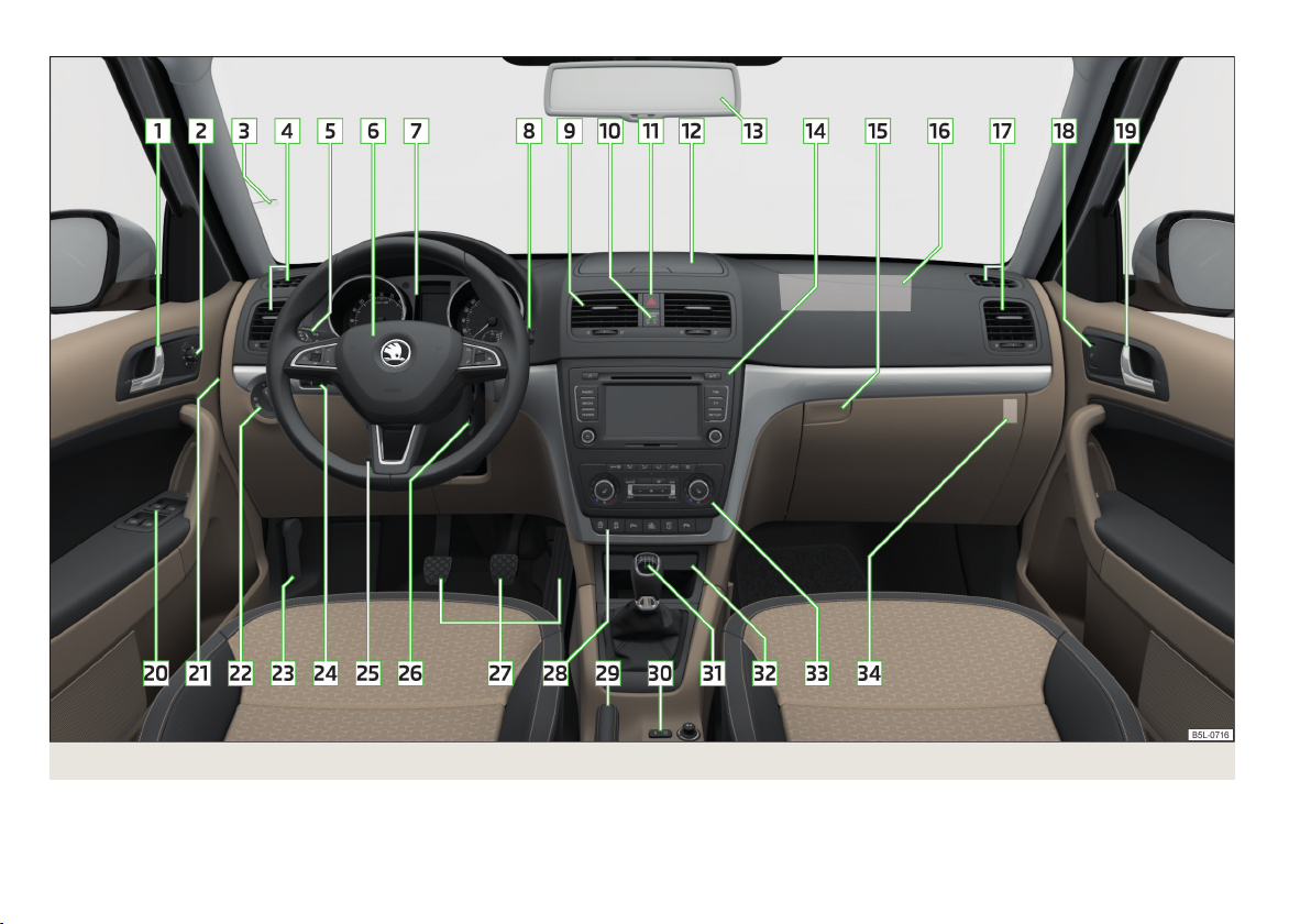
Fig. 1
8
Using the system
Cockpit
Page 12
Using the system
Cockpit
Overview
1
Door opening lever 37
2
Electric exterior mirror adjustment 59
3
Parking ticket holder 71
4
Air outlet vents 92
5
Operating lever:
Turn signal light, headlight and parking light, headlight flasher 49
›
Speed regulating system 147
›
6
Steering wheel:
With horn
›
With driver’s front airbag
›
With pushbuttons for radio, navigation system and mobile
›
phone
7
Instrument cluster: Instruments and indicator lights
8
Operating lever:
Windscreen wiper and wash system
›
Multifunction display 25
›
Information system 23
›
9
Air outlet vents
10
Warning light for the deactivated front seat passenger airbag 176
11
Switch for hazard warning lights
12
Storage compartment on the dash panel 71
13
Interior mirror
14
Depending on equipment fitted:
Radio
›
Navigation system
›
15
Storage compartment on the front passenger side
16
Front passenger airbag
17
Air outlet vents
18
Power window in the front passenger door 43
19
Door opening lever
20
Electric windows 41
21
Fuse box (on side of dash panel) 236
22
Light switch 47
23
Bonnet release lever 200
24
Regulator for the instrument lighting and regulator for the headlight beam range adjustment
25
Lever for adjusting the steering wheel 117
26
Ignition lock 119
27
Pedals 126
28
Bar with keys depending on the equipment fitted:
START STOP
›
Traction control TCS 137
›
Electronic Stability Control ESC 136
›
Parking aid 140
›
OFF ROAD-mode 138
›
Tyre control display 215
›
Park Assist
›
29
171
100
10
56
92
52
59
78
171
92
37
Handbrake lever 125
30
Central locking system
31
Depending on equipment fitted:
Gearshift lever (manual gearbox) 125
›
Selector lever (automatic gearbox)
›
32
Storage compartment 72
33
Depending on equipment fitted:
Operating controls for the heating
›
Operating controls for the air conditioning system 94
›
Operating controls for Climatronic
›
34
Key switch for switching off the front passenger airbag (in front
passenger storage compartment)
Note
The arrangement of the controls and switches and the location of some items on
right-hand drive models may differ from that shown in » Fig. 1. The symbols on
the controls and switches are the same as for left-hand drive models.
53, 48
149
143
36
127
94
95
176
Cockpit
9
Page 13
Instruments and Indicator Lights
Instrument cluster
Introduction
This chapter contains information on the following subjects:
Overview
Revolutions counter 11
Speedometer 11
Coolant temperature gauge 11
Display 12
Fuel gauge 12
Counter for distance driven
13
Display of the second speed
Auto Check Control
Fault display
If there is a fault in the instrument cluster, the Error message will appear in the
display. Have the fault rectified as soon as possible by a specialist garage.
WARNING
■
Concentrate fully at all times on your driving! As the driver, you are fully re-
sponsible for road safety.
■
Never operate the controls in the instrument cluster while driving, only
when the vehicle is stationary!
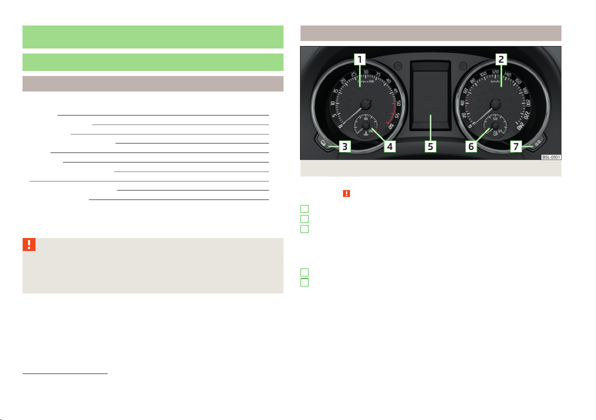
Overview
10
Fig. 2 Instrument cluster
13
13
13
1
Revolutions counter with warning lights » page 11
2
Speedometer with warning lights » page 11
3
Button for display mode:
›
›
›
4
Coolant temperature gauge » page 11
5
Display » page 12:
›
›
›
›
First read and observe the introductory information and safety warnings on page 10.
Time settings » page 13
Enable/disable the display of the second speed1) » page 13
Service intervals - Display of the number of days and kilometres remaining
until the next service1) » page 30
With counter for distance driven » page 13
With service interval display » page 30
With digital clock » page 13
With information system » page 23
1)
Applies to vehicles with a segment display.
10
Using the system
Page 14
6
Fuel gauge » page 12
7
Button for:
Reset daily trip counter » page 13
›
Setting the time
›
Enable / disable the mode selected by means of the 3 key
›
Revolutions counter
First read and observe the introductory information and safety warnings on page 10.
The red scale of the revolution counter 1 » Fig. 2 on page 10 indicates the range
in which the system begins to limit the engine speed. The system automatically
restricts the engine speed to a steady limit.
You should shift into the next highest gear before the red scale of the revolution
counter is reached, or select mode D on the automatic gearbox.
Follow the recommended gear to prevent engine speeds that are too high or too
low » page 24.
Speedometer
First read and observe the introductory information and safety warnings on page 10.
Warning against excessive speeds
An audible warning signal will sound when the vehicle speed exceeds 120 km/h1).
The audible warning signal is switched off when the vehicle speed falls below
120 km/h.
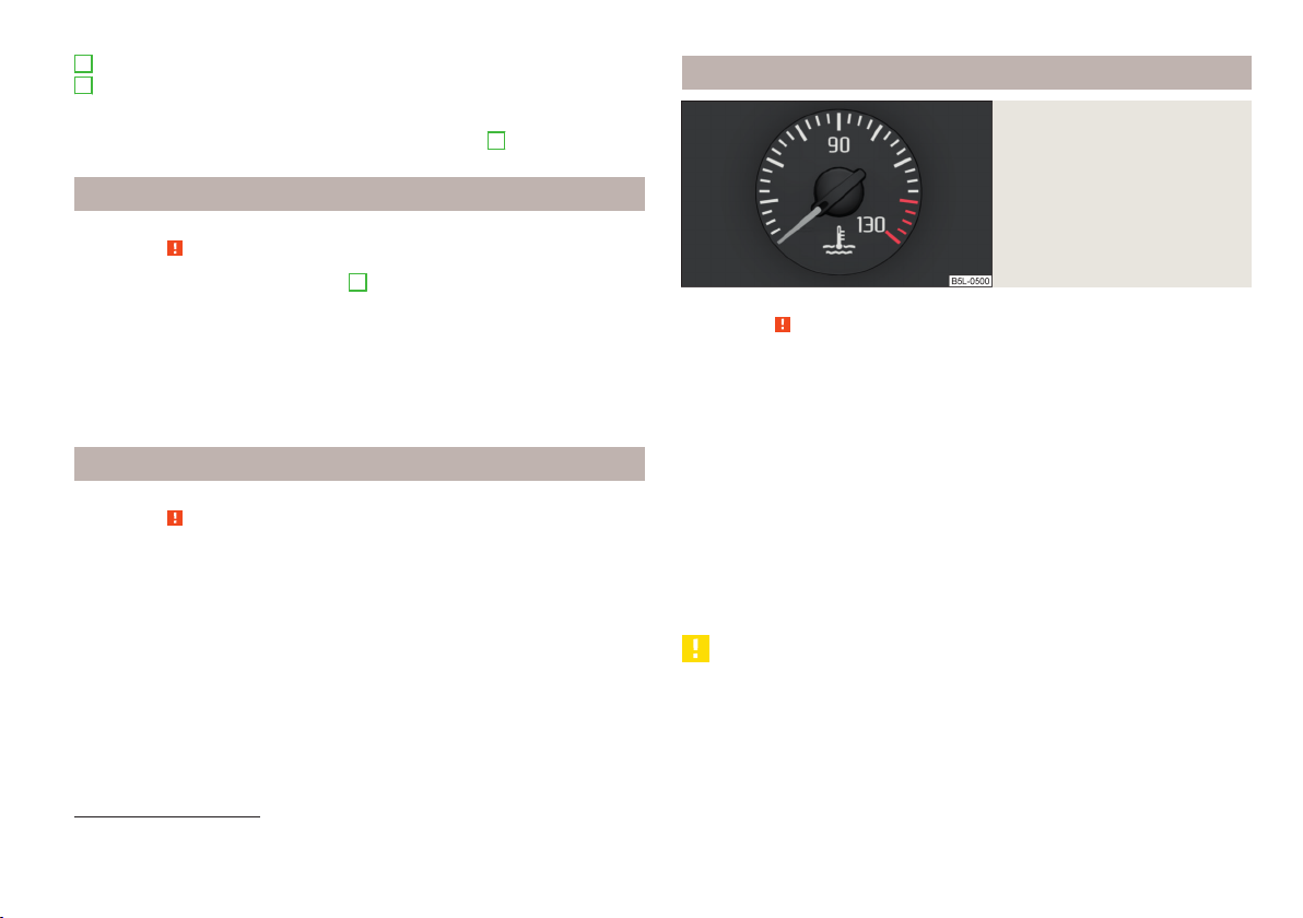
Coolant temperature gauge
First read and observe the introductory information and safety warnings on page 10.
The coolant temperature gauge » Fig. 3 only operates when the ignitions is
switched on.
Cold range
If the pointer is still in the left area of the scale, this indicates that the engine has
not yet reached its operating temperature. Avoid high speeds, full throttle and
high engine loads. This prevents possible damage to the engine.
The operating range
The engine has reached its operating temperature as soon as the pointer moves
into the mid-range of the scale. At very high ambient temperatures or heavy engine loads, the pointer may move even further to the right.
High temperature range
If the pointer reaches the red area of the scale, the coolant temperature is too
high. Further information » page 16.
Fig. 3
Coolant temperature gauge
CAUTION
Additional headlights and other attached components in front of the air inlet impair the cooling efficiency of the coolant.
1)
This function only applies to certain countries.
Instruments and Indicator Lights
11
Page 15
Display
Fig. 4
Display types
First read and observe the introductory information and safety warnings on page 10.
The instrument cluster can have one of the following types of display » Fig. 4.
Segment display
MAXI DOT display
CAUTION
Pull out the ignition key if coming in contact with the display (e.g. when cleaning)
to prevent any possible damage. On vehicles with the KESSY system, switch off
the ignition and open the driver's door.
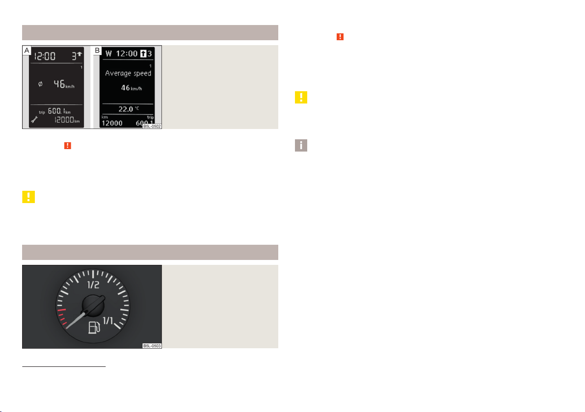
Fuel gauge
Fig. 5
Fuel gauge
First read and observe the introductory information and safety warnings on page 10.
The fuel gauge » Fig. 5 only operates if the ignition is switched on.
The fuel tank has a capacity of about 55 litres or 60 litres 1). If the amount of fuel
reaches the reserve area (the pointer reaches the red scale range), the indicator
symbol is illuminated » page 20 .
CAUTION
Never drive until the fuel tank is completely empty! The irregular supply of fuel
can cause misfiring. This can result in considerable damage to parts of the engine
and the exhaust system.
Note
After filling up, it can occur that during dynamic driving (e.g. numerous curves,
braking, driving downhill and climbing a steep hill) the fuel gauge indicates approx. a fraction less. When stopping or during less dynamic driving, the fuel gauge
displays the correct fuel level again. This is not a fault.
1)
Valid for Yeti 4x4.
12
Using the system
Page 16
Counter for distance driven
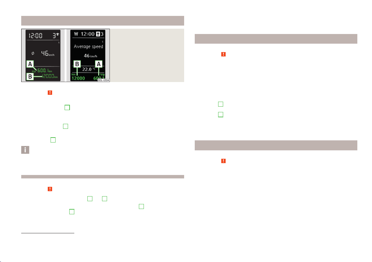
In vehicles equipped with the MAXI DOT display, it is also possible to set the clock
in the Time menu » page 29, Settings.
Fig. 6
Segment display / MAXI DOT display
First read and observe the introductory information and safety warnings on page 10.
Daily trip counter (trip)
The daily trip counter A » Fig. 6 indicates the distance since the counter was last
reset - in intervals of 100 metres or 1/10 of a mile.
Reset daily trip counter
Press and hold the 7 » Fig. 2 on page 10 button.
›
Odometer
The odometer
B
» Fig. 6 displays the total distance the vehicle has travelled.
Note
If the second speed display is enabled on vehicles with a segment display, this
speed will be shown instead of the odometer.
First read and observe the introductory information and safety warnings on page 10.
The clock is set with the buttons 3 and 7 » Fig. 2 on page 10.
Select the display that you wish to change with the button 3 and carry out the
change with the button
7
.
Display of the second speed
First read and observe the introductory information and safety warnings on page 10.
The display can show the current speed in mph1).
This feature is provided for driving in countries with different speed units.
MAXI DOT display
The display of the second speed can be set in the Alt. speed dis. menu
item » page 29, Settings.
Segment display
Press the 3 » Fig. 2 on page 10 key repeatedly until the odometer display flash-
›
es » page 13.
Press the 7 key while the display flashes.
›
The second speed is displayed instead of the odometer.
The display of the second speed can be disabled in the same way.
Auto Check Control
First read and observe the introductory information and safety warnings on page 10.
Vehicle condition
Certain functions and conditions of individual vehicle systems are checked continuously when the ignition is switched on.
Some error messages and other information are displayed in the MAXI DOT display. The messages are displayed simultaneously with the symbols in the MAXI
DOT display or with the warning lights in the instrument cluster » page 14.
1)
For models with the speedometer in mph, the second speed is displayed in km/h.
Instruments and Indicator Lights
13
Page 17
The menu item Vehicle status is shown in the main menu of the MAXI DOT display whenever at least one fault message exists. After selecting this menu, the
first of the error messages is displayed. Several error messages are shown on the
display under the message e.g. 1/3. This indicates that the first of a total of three
error messages is being displayed.
Warning symbols in the MAXI DOT display
Problem with the engine oil pressure
If the symbol is shown in the MAXI DOT display, you must have your vehicle
checked immediately by a specialist garage. The information about the maximum
permissible engine speed is displayed together with this symbol.
Clutches of the automatic gearbox are too hot
A symbol in the MAXI DOT display indicates that the temperature of the automatic gearbox DSG clutches is too high.
The following message is shown in the MAXI DOT display.
Gearbox overheated. Stop! Owner's manual!
Do not continue to drive! Stop the vehicle, switch off the engine, and wait until
the icon goes out – risk of gearbox damage! You can continue your journey as
soon as the symbol disappears.
Engine oil pressure too low » page 17
Check engine oil level,
engine oil sensor faulty
Problem with engine oil pressure » page 14
Clutches of the automatic gearbox DSG are
too hot
» page 203
» page 14
WARNING
If you have to stop for technical reasons, then park the vehicle at a safe distance from the traffic, switch off the engine and switch on the hazard warning
lights » page 52. The warning triangle must be set up at the prescribed distance - observe the national legal provisions when doing so.
Note
■
If the MAXI DOT display shows warning messages, these messages must be
confirmed in order to access the main menu » page 23, Using the information
system .
■
As long as the operational faults are not rectified, the symbols are always indicated again. After they are displayed for the first time, the symbols continue to be
indicated without any extra messages for the driver.
Warning lights
Introduction
This chapter contains information on the following subjects:
Handbrake
Brake system 15
Seat belt warning light
Generator
Door open 16
Coolant 16
Boot lid 17
Power steering
Engine oil
Traction Control System (ASR) 18
Electronic Stability Control (ESC) 18
Traction control (ASR) switched off 19
Antilock brake system (ABS)
Rear fog light
Bulb failure 19
Exhaust inspection system
Glow plug system (diesel engine)
Engine performance check (petrol engine)
Diesel particulate filter (diesel engine)
Fuel reserve 20
Airbag system
Tyre inflation pressure
Windscreen washer fluid level
20
20
15
15
16
17
17
19
19
19
19
21
21
21
14
Using the system
Page 18
Turn signal system 21
Fog lights
Cruise control system 22
Selector lever lock
OFF ROADmode 22
Main beam
The warning lights indicate certain functions or faults.
Some warning lights can be accompanied by acoustic signals and messages in the
display of the instrument cluster.
After switching on the ignition, some warning lights illuminate briefly as a func-
tion test.
If the tested systems are OK, the corresponding warning lights go out a few sec-
onds after switching on the ignition.
22
22
22
WARNING
■
Ignoring illuminated warning lights and related messages or instructions in
the display of the instrument cluster may lead to serious personal injury or
damage to the vehicle.
■
If you have to stop for technical reasons, then park the vehicle at a safe distance from the traffic, switch off the engine and switch on the hazard warning
lights » page 52. The warning triangle must be set up at the prescribed distance - observe the national legal provisions when doing so.
■
The engine compartment of your car is a hazardous area. The following
warning instructions must be followed at all times when working in the engine compartment » page 199, Engine compartment.
Handbrake
First read and observe the introductory information and safety warnings on page 14.
The indicator light comes on if the handbrake is applied.
An acoustic signal will sound if you drive the vehicle above 6 km/h for at least 3
seconds while the handbrake is applied.
The following message is shown in the MAXI DOT display.
Release parking brake!
Brake system
First read and observe the introductory information and safety warnings on page 14.
If the warning light lights up, the brake fluid level in the brake system is too
low.
The following message is shown in the MAXI DOT display.
Brake fluid: Owner's manual!
Stop the vehicle, switch off the engine, and check the level of the brake fluid » page 206.
If the warning light lights up together with the warning light , there is a
problem with the ABS.
WARNING
■
If you have to stop for technical reasons, then park the vehicle at a safe distance from the traffic, switch off the engine and activate the hazard warning
light system » page 52. The warning triangle must be set up at the prescribed distance - observe the national legal provisions when doing so.
■
The following guidelines should be observed when opening the bonnet and
checking the brake fluid level » page 199, Engine compartment.
■
If the warning light is displayed simultaneously with warning light
» page 19, Antilock brake system (ABS), do not continue your jour-
ney! Seek help from a specialist garage.
■
A fault to the braking system can increase the vehicle's braking distance -
risk of accident!
Seat belt warning light
First read and observe the introductory information and safety warnings on page 14.
The warning light comes on after the ignition is switched on as a reminder for
the driver and front passenger to fasten the seat belt.
The warning light goes out once the driver or front passenger has fastened
their seat belt.
Instruments and Indicator Lights
15
Page 19

If the driver or front passenger has not fastened their seat belt and the vehicle
speed is more than 20 km/h, the warning light flashes and you will hear an
acoustic signal.
If the seat belt is not fastened by the driver or front passenger during the next
90 seconds, the warning signal is deactivated and the indicator light lights up
permanently.
Further information » page 164, Seat belts.
Generator
First read and observe the introductory information and safety warnings
If the indicator light lights up when the engine is running, the vehicle battery is
not being charged.
Seek assistance from a specialist garage immediately. The electrical system requires checking.
on page 14.
WARNING
If you have to stop for technical reasons, then park the vehicle at a safe distance from the traffic, switch off the engine and switch on the hazard warning
lights » page 52. The warning triangle must be set up at the prescribed distance - observe the national legal provisions when doing so.
CAUTION
If the indicator light (cooling system fault) lights up in addition to the indicator light while driving, do not continue driving! Stop the engine - there is a risk
of engine damage! Seek help from a specialist garage.
Door open
First read and observe the introductory information and safety warnings on page 14.
The indicator light comes on, if one or several doors are opened.
The warning light comes on even when the ignition is switched off. The warning
light lights up for a maximum of 5 minutes.
On vehicles with MAXI DOT display, this indicator is replaced by a vehicle icon on
the display » page 25 .
WARNING
If you have to stop for technical reasons, then park the vehicle at a safe distance from the traffic, switch off the engine and switch on the hazard warning
lights » page 52. The warning triangle must be set up at the prescribed distance - observe the national legal provisions when doing so.
Coolant
First read and observe the introductory information and safety warnings on page 14.
If the warning light lights up or flashes, either the coolant temperature is too
high or the coolant level is too low.
The following message is shown in the MAXI DOT display.
Check coolant! Owner's manual!
Stop the vehicle, switch off the engine, and check the coolant level » page 205.
›
If the coolant level is too low, add coolant to the reservoir » page 206.
›
If the indicator light disappears after adding coolant and switching on the ig-
›
nition, you may continue your journey.
If the coolant level is within the specified range, but the indicator light is still
›
illuminated, check the fuse for the radiator fan and replace it if necessa-
ry » page 237, Fuses in the engine compartment.
If the coolant level and fan fuse are both OK but the indicator light is still illu-
›
minated, do not continue your journey!
Seek help from a specialist garage.
›
16
Using the system
Page 20

WARNING
■
If you have to stop for technical reasons, then park the vehicle at a safe distance from the traffic, switch off the engine and switch on the hazard warning
lights » page 52. The warning triangle must be set up at the prescribed distance - observe the national legal provisions when doing so.
■
Carefully open the coolant expansion bottle. If the engine is hot, the cooling
system is pressurized - risk of scalding! It is therefore best to allow the engine
to cool down before removing the cap.
■
Do not touch the radiator fan. The radiator fan may switch itself on automatically even if the ignition is off.
If the indicator light lights up, this indicates a complete failure of the power
steering and the steering assist has failed (significantly higher steering forces).
Seek assistance from a specialist garage immediately.
Further information » page 118, Power steering.
WARNING
If you have to stop for technical reasons, then park the vehicle at a safe distance from the traffic, switch off the engine and switch on the hazard warning
lights » page 52. The warning triangle must be set up at the prescribed dis-
tance - observe the national legal provisions when doing so.
Boot lid
First read and observe the introductory information and safety warnings on page 14.
The indicator light comes on if the boot lid is opened.
The warning light comes on even when the ignition is switched off. The warning
light lights up for a maximum of 5 minutes.
On vehicles with MAXI DOT display, this indicator is replaced by a vehicle icon on
the display » page 25 .
WARNING
If you have to stop for technical reasons, then park the vehicle at a safe distance from the traffic, switch off the engine and switch on the hazard warning
lights » page 52. The warning triangle must be set up at the prescribed distance - observe the national legal provisions when doing so.
Power steering
First read and observe the introductory information and safety warnings on page 14.
If the indicator light lights up, this indicates a partial failure of the power steering and the steering forces can be greater. Seek assistance from a specialist garage immediately.
Note
If the vehicle's battery has been disconnected and reconnected, the warning light
comes on after switching on the ignition. If the warning light does not go
out after moving a short distance, this means there is an error in the system. Seek
assistance from a specialist garage immediately.
Engine oil
First read and observe the introductory information and safety warn-
on page 14.
ings
The warning light lights up red (low oil pressure)
The following message is shown in the MAXI DOT display.
Oil pressure: Engine off! Owner's manual!
Stop the vehicle, switch off the engine, and check the level of the engine
oil » page 203.
If the warning light flashes, do not drive any further , even if the oil level is
correct! Also do not leave the engine running at an idling speed.
Seek help from a specialist garage.
The warning light lights up yellow (oil quantity too low)
The following message is shown in the MAXI DOT display.
Check oil level!
Stop the vehicle, switch off the engine, and check the level of the engine
oil » page 203.
Instruments and Indicator Lights
17
Page 21

The warning light will go out if the bonnet is left open for more than 30 seconds.
If no engine oil has been replenished, the warning light will come on again after
driving about 100 km.
The warning light flashes yellow (engine oil level sensor faulty)
The following message is shown in the MAXI DOT display.
Oil sensor: Workshop!
If the engine oil level sensor is faulty, the warning light flashes several times
and an audible signal sounds when the ignition is turned on.
Seek assistance from a specialist garage immediately.
WARNING
If you have to stop for technical reasons, then park the vehicle at a safe distance from the traffic, switch off the engine and switch on the hazard warning
lights » page 52. The warning triangle must be set up at the prescribed distance - observe the national legal provisions when doing so.
Traction Control System (ASR)
First read and observe the introductory information and safety warnings on page 14.
The warning light flashes to show that the ASR is currently operating.
If the warning light illuminates, there is a fault in the ASR.
The following message is shown in the MAXI DOT display.
Error: traction control (ASR)
Seek assistance from a specialist garage immediately.
If the warning light comes on after starting the engine, the TCS may be switch-
ed off for technical reasons.
Switch the ignition off and on again.
›
If the warning light does not illuminates after you switch the engine back on,
the ASR is fully functional again.
Further information » page 137, Traction Control System (TCS).
Note
If the vehicle's battery has been disconnected and reconnected, the indicator
light comes on after switching on the ignition. If the warning light does not
go out after moving a short distance, this means there is an error in the system.
Seek assistance from a specialist garage immediately.
Electronic Stability Control (ESC)
First read and observe the introductory information and safety warnings on page 14.
The warning light flashes to show that the ESC is currently operating.
If the warning light illuminates, there is a fault in the ESC.
The following message is shown in the MAXI DOT display.
Error: stabilization control (ESC)
Seek assistance from a specialist garage immediately.
If the warning light comes on after starting the engine, the ESC system may be
switched off for technical reasons.
Switch the ignition off and on again.
›
If the indicator light does not illuminate after you switch the engine back on,
the ESR is fully functional again.
Further information » page 136, Electronic Stability Control (ESC).
Note
If the vehicle's battery has been disconnected and reconnected, the indicator
light comes on after switching on the ignition. If the warning light does not
go out after moving a short distance, this means there is an error in the system.
Seek assistance from a specialist garage immediately.
18
Using the system
Page 22

Traction control (ASR) switched off
First read and observe the introductory information and safety warnings on page 14.
The warning light lights up when the ASR is turned off by pressing the Symbol
key » page 137, Traction Control System (TCS) or » page 136, Electronic Sta-
bility Control (ESC) .
The following message is shown in the MAXI DOT display.
Traction control (ASR) is deactivated.
Antilock brake system (ABS)
First read and observe the introductory information and safety warnings on page 14.
If the indicator light lights up, there is a fault in the ABS.
The following message is shown in the MAXI DOT display.
Error: ABS
The vehicle will only be braked by the normal brake system without the ABS.
Seek assistance from a specialist garage immediately.
Further information » page 137, Antilock brake system (ABS).
WARNING
■
If you have to stop for technical reasons, then park the vehicle at a safe distance from the traffic, switch off the engine and activate the hazard warning
light system » page 52. The warning triangle must be set up at the prescribed distance - observe the national legal provisions when doing so.
■
If the warning light » page 15 is displayed together with warning light ,
do not continue your journey! Seek help from a specialist garage.
■
A fault to the ABS system or the braking system can increase the vehicle's
braking distance – risk of accident!
Rear fog light
First read and observe the introductory information and safety warnings on page 14.
The warning light comes on when the rear fog light is switched on.
Further information » page 51.
Bulb failure
First read and observe the introductory information and safety warnings
The indicator light lights up if a bulb is faulty.
The indicator light lights up within a few seconds after switching on the igni-
tion or when a light with a faulty bulb is switched on.
The following message, for example, may be shown in the MAXI DOT display.
INFORMATION Check front right low beam!
Exhaust inspection system
If the indicator light lights up, there is a fault in the exhaust inspection system.
The system allows the vehicle to run in emergency mode.
Seek assistance from a specialist garage immediately.
Glow plug system (diesel engine)
The warning light lights up after the ignition has been switched on. Once the
light has gone out, the engine can be started immediately.
There is a fault in the glow plug system if the indicator light does not come on
at all or lights up continuously.
on page 14.
First read and observe the introductory information and safety warnings on page 14.
First read and observe the introductory information and safety warnings on page 14.
Instruments and Indicator Lights
19
Page 23

If the indicator light begins to flash while driving, a fault exists in the engine
control. The system allows the vehicle to run in emergency mode.
Seek assistance from a specialist garage immediately.
Engine performance check (petrol engine)
First read and observe the introductory information and safety warnings on page 14.
If the indicator light lights up, there is a fault in the engine control. The system
allows the vehicle to run in emergency mode.
Seek assistance from a specialist garage immediately.
Diesel particulate filter (diesel engine)
First read and observe the introductory information and safety warnings
The diesel particulate filter separates the soot particles from the exhaust. The
soot particles collect in the diesel particulate filter where they are burnt on a regular basis.
If the indicator light lights up, soot has accumulated in the filter.
To clean the filter, and where traffic conditions permit »
least 15 minutes or until the indicator light goes out.
4 or 5 Gear engaged (automatic transmission: position S).
Vehicle speed at least 70 km/h.
Engine speed between 1800-2500 rpm.
If the filter is properly cleaned, the warning icon goes out.
If the filter is not properly cleaned, the warning light does not go out and the
warning light begins to flash.
The following message is shown in the MAXI DOT display.
Diesel particle filter: Owner's manual!
The system allows the vehicle to run in emergency mode. After switching the ignition off and on again the indicator light, the indicator light also lights up.
Seek assistance from a specialist garage immediately.
on page 14.
, drive as follows for at
WARNING
■
The diesel particle filter achieves very high temperatures. Therefore do not
park in areas where the hot filter can come into direct contact with dry grass
or other combustible materials – there is the risk of fire!
■
Always adjust your speed to suit weather, road, region and traffic conditions. The recommendations indicated by the indicator light must not tempt
you to disregard the national regulations for road traffic.
CAUTION
■
As long as the indicator light lights up, one must take into account an in-
creased fuel consumption and in certain circumstances a power reduction of the
engine.
■
Using diesel fuel with an increased sulphur content can considerably reduce the
life of the diesel particle filter. A ŠKODA partner will be able to tell you which
countries use diesel fuel with a high sulphur content.
Note
■
To assist the combustion process of the soot particles in the filter, we recom-
mend that regularly driving short distances be avoided.
■
If the engine is turned off during the filter cleaning process or shortly after-
wards, the cooling fan may turn on automatically for a few minutes.
Fuel reserve
First read and observe the introductory information and safety warnings on page 14.
The indicator light will come on if the fuel level is less than 10.5 litres.
An audible signal sounds as a warning signal.
The following message is shown in the MAXI DOT display.
Please refuel. Range: ... km
Note
The text in the display goes out only after refuelling and driving a short distance.
20
Using the system
Page 24

Airbag system
First read and observe the introductory information and safety warnings on page 14.
If the warning light lights up, there is a fault in the airbag system.
The following message is shown in the MAXI DOT display.
Error: Airbag
The operational capability of the airbag system is monitored electronically, including when one of the airbags is switched off.
If a front, side or head airbag or belt tensioner has been switched off using the
vehicle system tester:
The warning lights up for approx. 4 seconds after switching on the ignition
›
and then flashes again for approx. 12 seconds.
The following message is shown in the MAXI DOT display.
Airbag / belt tensioner deactivated.
If the air bag was switched off using the key-operated switch on the side of the
dash panel on the passenger side:
The indicator light comes on for around 4 seconds after the ignition has been
›
switched on;
Switched off airbags are indicated in the middle of the dash panel by the indica-
›
tor light
in the display
coming on » page 176.
WARNING
If there is a fault in the airbag system, have it checked immediately by a specialist garage. Otherwise, there is a risk of the system not being activated in
the event of an accident.
Tyre inflation pressure
First read and observe the introductory information and safety warnings on page 14.
The warning light lights up, if there is a substantial drop in inflation pressure in
one of the tyres. Check and adjust the pressure in all tyres » page 213.
An audible signal sounds as a warning signal.
If the warning light flashes, there is a fault in the system.
Seek assistance from a specialist garage immediately.
Further information » page 215, Tyre pressure monitor.
Note
If the vehicle's battery has been disconnected and reconnected, the warning light
comes on after switching on the ignition. If the warning light does not go
out after moving a short distance, this means there is an error in the system. Seek
assistance from a specialist garage immediately.
Windscreen washer fluid level
First read and observe the introductory information and safety warnings
If the windscreen washer fluid level is too low, the indicator light comes on.
The following message is shown in the MAXI DOT display.
Top up wash fluid!
Top up with liquid » page 205.
Either the left or right indicator light flashes depending on the position of
the control lever.
If there is a fault in the turn signal system, the warning light flashes at twice its
normal rate. This does not apply when towing a trailer.
Switching off the hazard indicator light system is switched on will cause all of the
turn signal lights as well as both indicator lights to flash.
Further information » page 49.
on page 14.
Turn signal system
First read and observe the introductory information and safety warn-
on page 14.
ings
Instruments and Indicator Lights
21
Page 25

Fog lights
First read and observe the introductory information and safety warnings on page 14.
The warning light comes on when the fog lights are operating.
Further information » page 51.
Cruise control system
First read and observe the introductory information and safety warnings
The warning light comes on when the cruise control is active.
Further information » page 147.
Selector lever lock
If the indicator light lights up, operate the brake pedal.
Further information » page 127, Modes and use of selector lever.
OFF ROADmode
When the indicator light is lit, then the conditions for the engagement of OFF
ROAD mode are met » page 138 .
When the indicator flashes, it indicates the hill descent assistant is currently
engaged.
Further information » page 138, OFF ROAD-mode.
on page 14.
First read and observe the introductory information and safety warnings on page 14.
First read and observe the introductory information and safety warnings on page 14.
Main beam
First read and observe the introductory information and safety warnings on page 14.
The warning light comes on when the main beam is selected or when the
headlight flasher is operated.
Further information » page 49.
22
Using the system
Page 26
Information system
Driver information system
Introduction
This chapter contains information on the following subjects:
Using the information system
Ice warning 24
Gear recommendation 24
Door, boot or engine compartment warning 25
Compass point display 25
The information system provides the driver with alerts and messages about individual vehicle systems. This information and advice is shown in the instrument
cluster display or indicated by the illumination of the corresponding indicator light
in the instrument cluster.
Depending on the vehicle equipment, the information system provides the following advice and information.
Ice warning » page 24.
›
Recommended gear » page 24.
›
Door, boot lid or bonnet warning » page 25.
›
Compass display » page 25.
›
Data relating to the multi-function display (MFD) » page 25.
›
Warning against excessive speeds » page 27.
›
Data relating to the Maxi DOT display » page 28.
›
Service interval display » page 30.
›
Auto Check Control » page 13.
›
Selector lever positions for an automatic gearbox » page 127.
›
WARNING
Concentrate fully at all times on your driving! As the driver you are fully responsible for the operation of your vehicle.
23
Using the information system
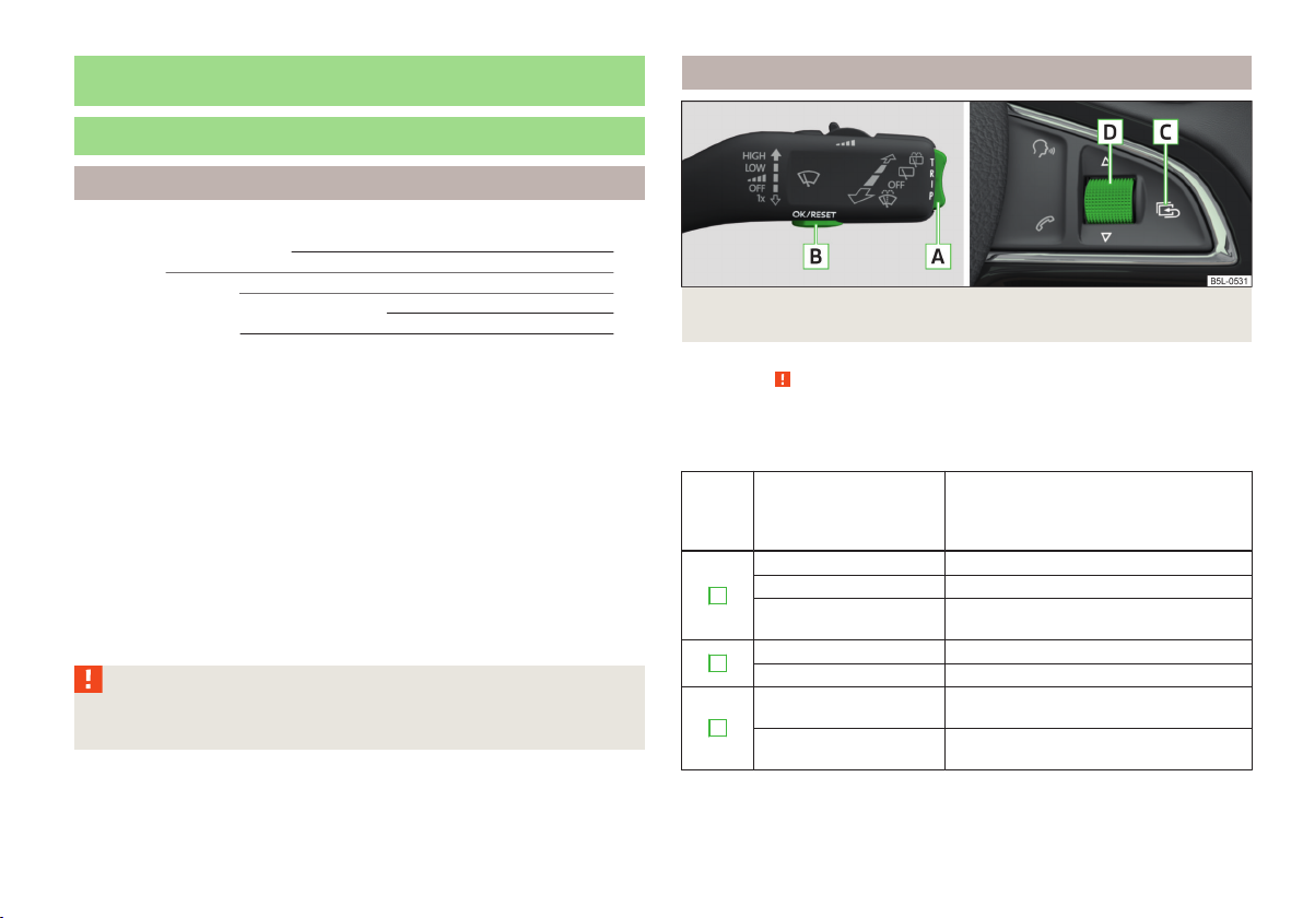
Fig. 7 Buttons/dial: on the operating lever / on the multifunction steering
wheel
First read and observe the introductory information and safety warnings on page 23.
Some functions of the information system can be operated using the buttons on
the multifunction steering wheel » Fig. 7 .
Description of the operation
Button/
di-
al
» Fig. 7
A
B
C
Action Operation
Briefly push up or down Select data
Briefly push up or down Set data values
Press and hold button
Press briefly Show data
Press briefly Confirm data
Press briefly
Press and hold button
Open main menu in the
MAXI DOT display » page 28
to go back one level in the menu of the
MAXI DOT display » page 28
Open main menu in the
MAXI DOT display » page 28
Information system
23
Page 27
Button/
di-
al
» Fig. 7
D
Action Operation
Turn upwards or down-
wards
Turn upwards or down-
wards
Press briefly Show data
Press briefly Confirm data
Set data values
Select data
Ice warning
First read and observe the introductory information and safety warnings on page 23.
Prompt in the MAXI DOT display
If the outside temperature while driving drops to below +4°C, the following icon
appears on the display in front of the temperature display . An audible signal is
emitted.
If the outside temperature is already below +4°C when turning the ignition on,
the icon appears immediately. An audible signal is emitted.
Prompt in the segment display
If the outside temperature while driving drops to below +4°C, the temperature
display will show up with the following icon before this occurs . An audible signal is emitted.
If the outside temperature is already below +4°C when turning the ignition on,
the temperature display and the icon appear immediately. An audible signal is
emitted.
After pressing Button
shown.
A
» Fig. 7 on page 23, the most recently displayed data is
WARNING
Even at temperatures around +4 °C, black ice may still be on the road surface!
Do not only rely upon the information given on the outside temperature display that there is no ice on the road.
Gear recommendation
First read and observe the introductory information and safety warnings on page 23.
Information on the selected gear
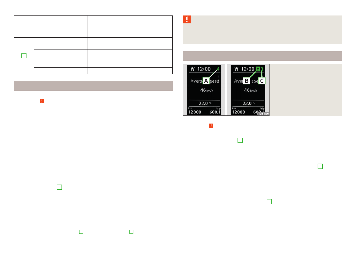
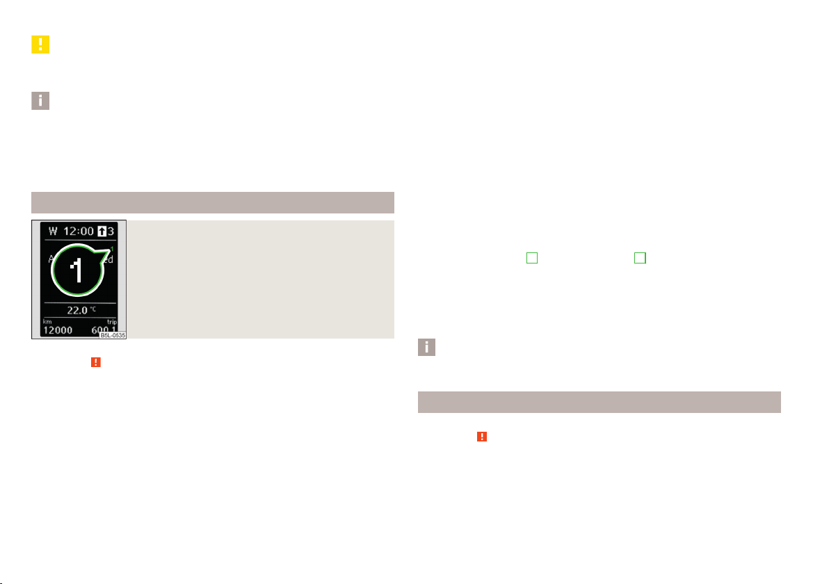
The currently engaged gear A is shown in the display » Fig. 8.
Recommended gear
In order to minimise the fuel consumption, a recommendation for shifting into another gear is indicated in the display.
If the system recognises that it is beneficial to change gear, an arrow
played. The arrow points up or down, depending on whether you should shift into
a higher or lower gear.
The gear recommendation is intended only for vehicles with a manual transmission or for vehicles with an automatic transmission in manual shift mode (Tiptronic).
For vehicles with manual transmission, the
gear.
Fig. 8
Information on the selected
gear / Gear recommendation
C
display indicates the recommended
B
1)
is dis-
1)
On vehicles with a segment display, the B arrow is displayed behind the C specification.
24
Using the system
Page 28

WARNING
The driver is always responsible for selecting the correct gear in different driving situations, such as overtaking.
For the sake of the environment
Correct shifting up has the following advantages.
■
It helps to reduce fuel consumption.
■
It reduces the operating noise.
■
It protects the environment.
■
It benefits the durability and reliability of the engine.
Compass point display
First read and observe the introductory information and safety warnings on page 23.
For vehicles with a factory fitted navigation system, an abbreviation for each
point of the compass (depending on the current direction of travel) is shown on
the top left-hand corner of the 1)display.
The compass point display only operates when the ignition is switched on.
Multifunction display (MFD)
Door, boot or engine compartment warning
First read and observe the introductory information and safety warnings on page 23.
Vehicles with a MAXI DOT display
If at least one door, the boot or bonnet is open, the display indicates the relevant
open door, boot or bonnet vehicle icon.
Vehicles with a segment display
If at least one door or the tailgate is open, the warning light in the instrument
cluster lights up » page 16.
If at least one door or the tailgate is open, the warning light in the instrument
cluster lights up » page 17.
An acoustic signal will also sound if you drive the vehicle above 6 km/h when a
door is open.
1)
Applies to vehicles using the MAXI DOT display.
Introduction
This chapter contains information on the following subjects:
Memory
Information overview
Warning at excessive speeds 28
The driving data is displayed on the multifunction display.
The multifunction display only operates if the ignition is switched on. After the ignition is switched on, the function that was last selected before switching off the
ignition is displayed.
For vehicles with a MAXI DOT display, the menu item MFD must be selected and
confirmed in the main menu » page 28, MAXI DOT display.
On vehicles with a MAXI DOT display, there is an option to fade out some of the
information » page 29, Settings.
WARNING
■
Concentrate fully at all times on your driving! As the driver you are fully re-
sponsible for the operation of your vehicle.
■
Even at temperatures around +4 °C, black ice may still be on the road surface! Do not only rely upon the information given on the outside temperature
display that there is no ice on the road.
Information system
26
26
25
Page 29
CAUTION
Pull out the ignition key if coming in contact with the display (e.g. when cleaning)
to prevent any possible damage.
Note
■
In certain national versions the displays appear in the Imperial system of meas-
ures.
■
If the display of the second speed is activated in mph, the current speed is not
indicated in km/h on the display.
■
The amount of fuel consumed will not be indicated.
Memory
Fig. 9
Multi-function display - Display example of the memory
Total-trip memory (memory 2)
The total trip memory collates the data from any number of individual trips up to
a total of 19 hours and 59 minutes or a 1999 km distance or, for vehicles with a
MAXI DOT display, 99 hours and 59 minutes, or a 9999 km distance.
The memory is deleted when either of these limits is reached and the calculation
starts all over again.
Unlike the single-trip memory, the total-trip memory is not deleted after a period
of interruption of driving of 2 hours.
Select memory
Select the corresponding element of the multifunction display » page 23, Using
›
the information system.
Confirm the element again to switch between the individual memories.
Reseting
Select the corresponding element of the multifunction display » page 23, Using
›
the information system.
Select the desired memory.
›
Press and hold button B or adjustment wheel D » Fig. 7 on page 23.
›
The following values of the selected memory are set to zero.
Average fuel consumption.
›
Distance driven.
›
Average speed.
›
Driving time
›
First read and observe the introductory information and safety warnings on page 25.
The multifunction display is equipped with two automatic memories, 1 and 2. The
selected memory is shown in the Display » Fig. 9.
Single-trip memory (memory 1)
The single-trip memory collates the driving information from the moment the ignition is switched on until it is switched off.
New data will also flow into the calculation of the current driving information if
the trip is continued within 2 hours after switching off the ignition.
If the trip is interrupted for more than 2 hours, the memory is automatically
erased.
26
Using the system
Note
Disconnecting the vehicle battery will delete all memory data.
Information overview
First read and observe the introductory information and safety warnings on page 25.
The amount of information displayed may differ depending on the equipment.
Outside temperature
The current outside temperature is displayed.
For vehicles with a MAXI DOT display this information is always shown.
Page 30

Driving time
The time travelled since the memory was last erased is displayed.
If you want to measure the time travelled from a particular moment in time on, at
this moment, reset the memory by setting the button to zero » page 26, Memory.
The maximum time indicated in both memories is 19 hours and 59 minutes and on
vehicles which are fitted with a MAXI DOT display, it is 99 hours and 59 minutes.
The indicator is set back to zero if this period is exceeded.
Current fuel consumption
The current fuel consumption level is displayed in litres/100 km1). You can use this
information to adapt your driving style to the desired fuel consumption.
The display appears in litres/hour if the vehicle is stationary or driving at a low
speed2).
Average fuel consumption
The average fuel consumption since the memory was last erased is displayed in
litres/100 km1).
If you wish to determine the average fuel consumption over a certain period of
time, you must set the memory at the start of the new measurement to
zero » page 26, Memory. After erasing the memory, no value is displayed until you
have driven approx. 300 m.
The display is updated regularly while you are driving.
Range
The range indicates the distance you can still drive with your vehicle based on the
level of fuel in the tank and the same style of driving as before.
The display is shown in steps of 10 km. After lighting up of the indicator light
the display is shown in steps of 5 km.
The fuel consumption over the last 50 km is used to calculate the information.
The range will increase if you drive in a more economical manner.
If the memory is set to zero (after disconnecting the battery), a fuel consumption
of 10 l./100 km is calculated for the range; afterwards the value is updated according to the style of driving.
Distance travelled
The distance travelled since the memory was last erased is displayed.
If you want to measure the distance travelled from a particular moment in time
on, at this moment, reset the memory by setting the button to zero » page 26,
Memory.
The maximum distance indicated in both memories is 1 999 km or 9 999 km on
vehicles with a MAXI DOT display. The indicator is set back to zero if this period is
exceeded.
Average speed
The average speed since the memory was last erased is displayed in km/hour .
To determine the average speed over a certain period of time, set the memory to
zero at the start of the measurement » page 26, Memory.
After erasing the memory, no data will appear for the first 300 m driven.
The display is updated regularly while you are driving.
Current driving speed
The current speed displayed is identical to the display on the speedometer
2
» Fig. 2 on page 10 .
Oil temperature
If the engine oil temperature is in the range 80-110 °C, the engine operating temperature is reached.
If the oil temperature is lower than 80 °C or above 110 °C, avoid high engine revs,
full throttle and high engine loads.
If the oil temperature is lower than 50 °C or if a fault in the system for checking
the oil temperature is present, . symbols are displayed instead of the oil temperature.
Warning against excessive speeds
Set the speed limit, for example, for the maximum permissible speed in
town » page 28, Warning at excessive speeds.
1)
On some models in certain countries, the display appears in kilometres/litre.
2)
On some models in certain countries, – -.- km/ltr. is displayed when the vehicle is stationary.
Information system
27
Page 31

Warning at excessive speeds
First read and observe the introductory information and safety warnings on page 25.
Adjust the speed limit while the vehicle is stationary
Select the menu item Speed warning (MAXI DOT display) or (segment dis-
›
play).
Activate the speed limit option by confirming this menu item1).
›
Set the desired speed limit, e.g. 50 km/h.
›
Store the speed limit by confirming the set value, or wait several seconds; your
›
settings will be saved automatically.
The speed limit can be adjusted from 30 km/h to 250 km/h in 5 km/h increments.
Adjusting the speed limit while the vehicle is moving
Select the menu item Speed warning (MAXI DOT display) or (segment dis-
›
play).
Drive at the desired speed, e.g. 50 km/h.
›
Confirm the current speed as the speed limit.
›
If you wish to adjust the set speed limit, you can do so in 5 km/h intervals (e.g. the
accepted speed of 47 km/h increases to 50 km/h or decreases to 45 km/h).
Store the speed limit, or wait several seconds; your settings will be saved auto-
›
matically.
Change or disable speed limit
Select the menu item Speed warning (MAXI DOT display) or (segment dis-
›
play).
By confirming the stored value, the speed limit is disabled.
›
By reconfirming, the option to change the speed limit is activated.
›
If the set speed limit is exceeded, an audible signal will sound as a warning. The
menu item Speed warning (MAXI DOT display) or (Segment display) appears in
the display at the same time as the set threshold.
The set speed limit value remains stored even after switching off the ignition.
MAXI DOT display
Introduction
This chapter contains information on the following subjects:
Main menu
Settings 29
The MAXI DOT display provides you with information about the current operating
state of your vehicle. Depending on the vehicle equipment, it also provides you
with data relating to the radio, multifunction display (MFD), mobile phone, navigation system, automatic gearbox and devices connected via the MDI input. Furthermore, it allows the adjustment of some other features of your vehicle.
WARNING
Concentrate fully at all times on your driving! As the driver you are fully responsible for the operation of your vehicle.
CAUTION
Pull out the ignition key if coming in contact with the display (e.g. when cleaning)
to prevent any possible damage.
Main menu
First read and observe the introductory information and safety warnings on page 28.
In order to activate the primary menu MAIN MENU, press and hold down Button
A
or C » Fig. 7 on page 23 . By briefly pressing the C button you will reach one
level higher.
28
1)
If no value is set the output value 30 km/h is automatically displayed.
28
Using the system
Page 32

Main menu points
The following information can be selected (depending on the equipment installed
in the vehicle).
■
MFD (Multifunction display) » page 25
■
Audio » Operating instructions for the radio
■
Navigation » Operating instructions for the navigation system
■
Phone » page 100;
■
Aux. heating » page 97
■
Assistants » page 151
■
Vehicle status » page 13
■
Settings » page 29
The Audio and Navigation menu items are only displayed when the factory-fitted
radio or navigation system is switched on.
The Aux. heating menu item is only displayed if the vehicle is equipped with factory-fitted auxiliary heating.
The menu item Assistants is only displayed if the vehicle is fitted with fatigue detection.
Note
■
If warning messages are displayed, these messages must be verified to access
the main menu » page 23, Using the information system.
■
If the display is not activated at that moment, the menu always shifts to one of
the higher levels after approx. 10 seconds.
■
Using the factory-fitted radio or navigation system » Radio operating instruc-
tions or» navigation system operating instructions.
Settings
First read and observe the introductory information and safety warnings on page 28.
You can change certain settings by means of the MAXI DOT display. The current
menu item is shown in the top of the display under a line.
The following information can be selected (depending on the equipment installed
in the vehicle).
Language
You can set the language for the display texts here.
MFD data
Activate or deactivate certain displays of the multifunction display here.
Convenience
The following functions can be activated, deactivated or adjusted here:
Switch on/off the function for automatically closing the
window and panoramic tilt/slide sunroof in a locked ve-
Rain closing
hicle when it starts raininga). If the function is set and it
is not raining, the windows including the panoramic tilt/
slide sunroof will close automatically after approx.
12 hours.
Switch on/off the audible signal indicating activation of
ATA confirm
the anti-theft alarm system. Further information » page 39, Anti-theft alarm system.
Switch on/off the central locking and automatic locking
Central locking
function. Further information » page 36, Individual
settings.
Only convenience mode for the driver window or for all
Window op.
of the windows can be adjusted here. Further information » page 43, Window convenience operation.
Switch on/off the function for mirror lowering on the
Mirror down
front passenger side when engaging the reverse gearb).
Further information » page 60, Fold in passenger's
mirror.
Switch on/off the function for left and right exterior
Mirror adjust.
mirror setting simultaneously. Further information » page 59, Synchronous adjustment of both mirr-
rors.
Factory setting Restore the Convenience factory setting.
a)
This function is only available on vehicles with a rain sensor.
b)
This function is only available on vehicles with an electrically adjustable driver seat.
Lights & Vision
The following functions can be activated, deactivated or adjusted here:
Information system
29
Page 33

Coming Home
ing Home function. Further information » page 51,
COMING HOME / LEAVING HOME.
Switch on/off and adjust the light duration of the Com-
Switch on/off and adjust the light duration of the Com-
Leaving Home
ing Home function. Further information » page 51,
COMING HOME / LEAVING HOME.
Enable / disable the daytime running lights. Further in-
Dayl. dri. light
formation » page 48, Daylight running lights (DAY
LIGHT).
Switch on/off the function for automatic rear window
Rear wiper
wiping. Further information » page 57, Automatic rear
window wiping.
Switch on/off the convenience flashing function. Fur-
Lane ch. flash
ther information » page 49, “Convenience turn signal”.
Travel mode
Switch on/off the travel model function. Further information » page 50, Tourist lights (Travel mode).
Factory setting Restore the factory setting for the lighting.
Time
The time, time format (12 or 24 hour indicator) and the changeover between summer/winter time can be set here.
Winter tyres
Here, the speed and the switching on and off of the acoustic signals when exceeding this speed can be adjusted. This function is, for example, used for winter
tyres where the maximum permissible speed is lower than the maximum speed of
the vehicle » page 212, Tyres and wheel rims.
As soon as the parking procedure is completed, an audible signal sounds and the
following message appears in the information display.
Winter tyres: max. speed … km/h.
Units
The units for the temperature, consumption and distance driven can be set here.
Assistants
The tones of the audible signals for the parking aid can be adjusted here.
Further information » page 140, Parking aid.
Alt. speed dis.
Here, the display of the second speed in mph1) can be activated.
Further information » page 13, Display of the second speed.
Service
The days and kilometres remaining until the next service can be displayed here.
Further information » page 30, Service interval display.
Factory setting
The factory setting of the functions of the MAXI DOT display can be restored here.
Service interval display
Introduction
This chapter contains information on the following subjects:
Prompt in the segment display 31
Prompt in the MAXI DOT display
Before the next service interval is reached, a message concerning the kilometres
and days remaining until the next service is due is shown for about 10 seconds
after the ignition is switched on.
This information can also be displayed manually with the ignition at all times.
The kilometre indicator or the days indicator reduces in steps of 100 km or, where
applicable, days until the service due date is reached.
Note
■
Information is retained in the Service Interval Display even after the vehicle bat-
tery is disconnected.
■
If the instrument cluster is exchanged after a repair, the correct values must be
entered in the counter for the Service Interval Display. This work is carried out by
a specialist garage.
■
In some national versions the displays appear in the Imperial system of measurement.
■
For more information on the service intervals, see » page 182, Service intervals.
31
1)
For models with the speedometer in mph, the second speed is displayed in km/h.
30
Using the system
Page 34

Prompt in the segment display
Fig. 10
Segment display: Example of a
message
Display the days and distance until the next service interval
Press Button 3 » Fig. 10 continuously at any time when the ignition is switched
on to display the remaining distance and days until the next service interval.
Information on the oil change service is displayed at first, followed by information
on the inspection when button 3 is pressed again.
The number 1 or 2 is displayed in position A.
›
The symbol and the number of days remaining until the next service interval
›
are displayed in position B.
The symbol and the number of kilometres remaining until the next service in-
›
terval are displayed in position C.
First read and observe the introductory information given on page 30.
Explanation of a graphic » Fig. 10.
service interval due
A
Differentiating between types of service
B
Days remaining until the next service interval
C
Kilometres remaining until the next service interval
Differentiating between types of service
The service type is determined by the number in position
Oil change service
Inspection
Service due
If a service becomes due, then the following information is displayed for about 10
seconds » Fig. 10.
The number 1 or 2 is displayed in position
›
The symbol and the number of days remaining until the next service interval
›
are displayed in position
The symbol and the number of kilometres remaining until the next service in-
›
terval are displayed in position
As soon as the due date for the service has been reached, the flashing icon
and the message OIL CHNG or INSPEC_ appear in the display for about 20 seconds after the ignition has been switched on.
1)
The kilometres remaining until the next service interval are displayed instead of the odometer.
B
.
C
A
.
.
1)
A
» Fig. 10 .
Prompt in the MAXI DOT display
First read and observe the introductory information given on page 30.
Oil change service
If an oil change service is due, the following message appears: Oil change in … km
or … days.
As soon as the service interval date has been reached, the message Oil change
now! appears once the ignition has been switched on!
Inspection
If an inspection is due, the following message appears: Inspection in ... km or ...
days.
As soon as the service interval date has been reached, the message Inspection
now! appears once the ignition has been switched on!
Displaying the distance and days until the next service interval
You can view the remaining distance and days until the next service appointment
at any time when the ignition is switched on by going to the Service menu
item » page 29, Settings or from the Vehicle status in the main menu of the Maxi
DOTdisplay. » page 28, Main menu .
The following message is displayed for 10 seconds.
Oil change ... km / ... days
Inspection ... km / ... days
Information system
31
Page 35

Unlocking and opening
Unlocking and locking
Introduction
This chapter contains information on the following subjects:
Vehicle key
Unlocking/locking with the key 33
Unlocking/locking with the remote control 34
Synchronising the remote control 34
Unlocking/locking – KESSY 35
Safe securing system 35
Individual settings
Locking/unlocking the vehicle from the inside 36
Child safety lock
Opening/closing a door
Your car is equipped with a central locking system.
The central locking system allows you to lock and unlock all doors, the fuel filler
flap1) and tailgate2) at the same time.
The safe securing system » page 35 is integrated in the central locking system.
Once the car is locked from the outside, the door locks3) are automatically blocked
by the safe securing system »
The following is true after unlocking2).
The doors, the boot lid and the fuel filler flap1) are unlocked.
›
The interior light operated via the door contact illuminates.
›
The safe securing system is switched off3).
›
The indicator light in the driver door stops flashing.
›
The anti-theft alarm system is deactivated.
›
.
33
36
2)
The following is true after locking
The doors, the boot lid and the fuel filler flap1) are locked.
›
The interior light operated via the door contact goes out.
›
The safe securing system is switched on3).
›
The indicator light in the driver door begins flashing.
›
The anti-theft alarm system is activated.
›
Displaying an error
If the warning light in the driver's door initially flashes quickly for around 2 seconds, and then lights up for 30 seconds without interruption before flashing
again slowly, you will need to seek the assistance of a specialist garage.
.
WARNING
If the car is locked and the safe securing system activated, no people must re-
main in the car as it will then not be possible to either unlock a door or open a
window from the inside. The locked doors make it more difficult for rescuers
to get into the vehicle in an emergency – risk to life!
37
37
Note
■
In the event of an accident in which the airbags are deployed, the locked doors
are automatically unlocked in order to enable rescuers to gain access to the vehicle.
■
Only the driver's door can be unlocked or locked using the key if the central
locking system fails » page 33. The other doors and the boot lid can be emergency locked or unlocked.
■
Emergency locking of the door » page 232.
■
Emergency unlocking of the boot lid » page 233.
1)
Applies to vehicles with a lockable fuel filler cap.
2)
Depending on the individual setting » page 36.
3)
This function only applies to certain countries.
32
Using the system
Page 36

Vehicle key
Fig. 11 Key types
First read and observe the introductory information and safety warnings
Explanation of graphic » Fig. 11
Keys without remote control
Keys with remote control (remote control keys)
The transmitter with the battery is housed in the handle of the remote control
key. The receiver is located in the interior of the vehicle.
The operating range of the remote control key is approx. 30 m. But this range of
the remote control can be reduced if the batteries are weak.
The wireless key has a flip-out key bit.
The spare key must by initialised by a specialist garage after the receiver unit is
repaired or replaced. Only then can the remote control key be used again.
on page 32.
WARNING
■
Always withdraw the key whenever you leave the vehicle - even if it is only
for a short time. This is particularly important if children are left in the vehicle.
Otherwise, the children might start the engine or operate electrical equipment
(e.g. power windows) – risk of injury!
■
Do not withdraw the ignition key from the ignition lock until the vehicle has
come to a stop. The steering lock might otherwise engage unintentionally –
risk of accident!
CAUTION
■
Each key contains electronic components; therefore it must be protected
against moisture and severe shocks.
■
Keep the groove of the keys absolutely clean. Impurities (textile fibres, dust,
etc.) have a negative effect on the functionality of the locking cylinder and ignition lock.
■
The battery must be replaced if the central locking or anti-theft alarm system
does react to the remote control at less than approx. 3 metres away » page 231.
Note
If you lose a key, please contact a specialist garage, who will be able to provide
you with a new one.
Unlocking/locking with the key
Fig. 12
Left side of the vehicle: Turning
the key for unlocking and locking the vehicle
First read and observe the introductory information and safety warnings
Unlocking
Turn the key in the driver's door locking cylinder in the direction of travel (un-
›
locking position)
Locking
Turn the key in the locking cylinder of the driver's door in the opposite direction
›
of travel (lock position) B » Fig. 12.
If the driver's door has been opened, the vehicle cannot be locked.
on page 32.
A
» Fig. 12.
Unlocking and opening
33
Page 37

Unlocking/locking with the remote control
Fig. 13
Remote control key
First read and observe the introductory information and safety warnings on page 32.
Explanation of graphic » Fig. 13
Unlocking the vehicle
Locking the vehicle
Unlocking the boot lid
A
Folding out/folding up of the key bit
B
Warning light
Unlocking
The turn signal lights flash twice as confirmation that the vehicle has been unlocked.
If you unlock the vehicle and do not open a door or the boot lid within the next
30 seconds, the vehicle will lock again automatically and the safelock system1) or
anti-theft alarm system will be switched on. This function is intended to prevent
the car being unlocked unintentionally.
Locking
The turn signal lights flash once as confirmation that the vehicle has been locked.
If the doors or the boot lid remain open after the vehicle has been locked, the
turn signal lights do not flash until they have been closed.
Checking the battery condition
If the red indicator light
the remote control key, the battery is empty. Replace the battery » page 231.
B
» Fig. 13 does not flash when you press a button on
WARNING
If the car is locked from the outside and the safelock system is switched on,
there must not be any person in the car as it is then not possible to open either a door or a window from the inside. The locked doors make it more difficult for rescuers to get into the vehicle in an emergency – risk to life!
CAUTION
■
Only operate the remote control when the doors and boot lid are closed and the
vehicle is in your line of sight.
■
If the driver door is open, the vehicle cannot be locked using the remote control
key.
■
The operation of the remote control may temporarily be affected by signal interference from transmitters close to the car and which operate in the same frequency range.
Note
For vehicles with anti-theft alarm the acoustic signals can also be activated/deactivated by locking/unlocking » page 29.
Synchronising the remote control
First read and observe the introductory information and safety warnings
If the vehicle does not unlock when pressing the remote control, the key may not
be synchronised. This can occur when the buttons on the remote control key are
actuated a number of times outside of the operative range of the equipment or
the battery in the remote control key was replaced.
Synchronise the key as follows.
Press any button on the remote control key.
›
Pressing of the button means that the door will unlock with the key within 1 mi-
›
nute.
on page 32.
1)
This function only applies to certain countries.
34
Using the system
Page 38

Unlocking/locking – KESSY
Fig. 14 KESSY: Name of the zones / sensors in the front door handle
First read and observe the introductory information and safety warnings
Unlocking or locking areas » Fig. 14
A
Front door left
B
Front door right
C
Luggage compartment lid
The KESSY system (Keyless Entry Start Exit System) enables unlocking and locking of the vehicle without actively using the remote control key. The key must be
in one of the areas
Unlocking
Grab the door handle of the front door or cover the sensor 2 » Fig. 14 with the
›
whole palm of your hand »
Locking
Touch the sensor 1 » Fig. 14 with your fingers.
›
On vehicles fitted with automatic gearbox, the selector lever must be moved into
the position P before unlocking.
Switching off the safelock system
Touch the sensor 1 » Fig. 14 twice within 2 seconds with your fingers.
›
If you cover the sensor
vehicle, it is not unlocked.
If the vehicle is locked via the sensor
in the following 2 seconds via the sensor 2 - prevents accidental unlocking.
on page 32.
A,
B or C » Fig. 14 (about 1.5 meters away from the vehicle).
.
2
at the same time as the sensor 1 when unlocking the
1
, it will not be possible to unlock it again
The KESSY system can find the valid key, even if it was left in the front of the vehicle's roof for example D » Fig. 14. It is therefore not always necessary to know
where the key is.
Always check to see whether the vehicle is locked.
Further information about the KESSY system » page 38.
CAUTION
■
Do not use objects which might prevent direct contact between the hand and
the grip sensor.
■
Some types of gloves can impair the function of the grip sensor.
■
After leaving the vehicle, it does not lock automatically, the procedure for lock-
ing the vehicle must therefore be observed.
■
If the battery in the key is weak or discharged, the vehicle may not be unlocked
or locked via the KESSY system. In this case, use the emergency unlocking or
emergency locking on the driver's door » page 232.
Safe securing system
First read and observe the introductory information and safety warnings on page 32.
The door locks are blocked automatically if the vehicle is locked from the outside.
Afterwards, it is not possible to open the doors with the door handle either from
the inside or from the outside.
This fact is pointed out by the following message on the display of the instrument
cluster after switching out the ignition.
Check SAFELOCK! Owner's manual!
CHECK DEADLOCK
If the vehicle is locked and the safe securing system is switched off, the door can
be opened separately from the inside by a single pull on opening lever.
Switching off
The safelock can be switched off by locking twice within 2 seconds.
Switching on
The safelock switches on automatically the next time the vehicle is locked and
unlocked.
Unlocking and opening
35
Page 39

Switch-on display
The indicator light flashes for around 2 seconds in quick succession, afterwards it
begins to flash evenly at longer intervals.
Switch-off display
The indicator light in the driver door flashes for about 2 seconds fast, goes out
and starts to flash at longer intervals after about 30 seconds.
WARNING
If the car is locked and the safe securing system activated, no people must remain in the car as it will then not be possible to either unlock a door or open a
window from the inside. The locked doors make it more difficult for rescuers
to get into the vehicle in an emergency – risk to life!
Note
This function only applies to certain countries.
Automatic locking/unlocking
All doors are locked from a speed of around 15 km/h. The button in the handle of
the boot lid is deactivated.
If the ignition key is withdrawn, the car is then automatically unlocked again. In
addition, it is possible for the driver or front passenger to unlock the car by pressing the central locking button .
The vehicle doors can be unlocked and opened at any time by pulling once on the
door opening lever.
WARNING
Locked doors prevent unwanted entry into the vehicle from outside, for example at road crossings.
Locking/unlocking the vehicle from the inside
Individual settings
First read and observe the introductory information and safety warnings on page 32.
The following central locking functions can be set via the MAXI DOT display » page 29, Settings .
Opening a single door
This function makes it possible to only unlock the driver's door. The other doors,
the fuel filler flap and the boot lid remain locked and are only unlocked after being opened again.
Unlocking a vehicle side door
This function enables you to unlock both doors on the driver's side. The other
doors, the fuel filler flap and the boot lid remain locked and are only unlocked after being opened again.
Unlocking the vehicle with the KESSY system
This function enables you to unlock all the doors, individual doors, both doors on
the left or right vehicle side. The other doors, the fuel filler flap and the boot lid
remain locked and are only unlocked after being opened again.
36
Using the system
Fig. 15
Central locking button
First read and observe the introductory information and safety warnings on page 32.
If the vehicle was not locked from the outside, you can also unlock or lock it with
the button » Fig. 15 , even without the ignition being switched on. While a door is
opened, the vehicle cannot be locked.
Locking
Press on the button in the » Fig. 15 area.
›
The symbol in the button comes on.
Unlocking
Press the button in the » Fig. 15 area.
›
Page 40

The symbol in the button is no longer illuminated.
The following applies if your vehicle has been locked using the central locking
button.
It is not possible to open the doors or the boot lid from the outside (safety fea-
›
ture, e.g. when stopping at traffic lights etc.).
The doors can be unlocked and opened from the inside by a single pull on the
›
opening lever of the respective door.
In the event of an accident in which the airbags are deployed, the locked doors
›
are automatically unlocked in order to enable rescuers to gain access to the vehicle.
WARNING
■
Doors locked from the inside make it difficult for rescuers to get into the ve-
hicle in an emergency – risk to life!
■
Never leave children unattended in the vehicle.
■
If the safelock system is switched on » page 35, the door opening lever and
the central locking buttons do not operate.
Switching on
Turn the slot of the safety lock in the direction of the arrow » Fig. 16 (mirror-
›
inverted on the right-hand door).
Switching off
Turn the slot of the safety lock in the opposite direction to the arrow » Fig. 16
›
(mirror-inverted on the right-hand door).
Opening/closing a door
Child safety lock
Fig. 16
Parental Control: Left rear door
First read and observe the introductory information and safety warnings on page 32.
The child safety lock prevents the rear door from being opened from the inside.
The door can only be opened from the outside.
You can switch the child safety lock on and off using the vehicle key.
Door handle/door opening lever:
Fig. 17
First read and observe the introductory information and safety warnings on page 32.
Opening from the outside
Unlock the vehicle and pull on door handleA » Fig. 17 on the door you wish to
›
open.
Opening from the inside
Pull on door opening lever
›
from you.
Closing from the inside
Grasp pull handle C and close the door.
›
B
of the respective door and push the door away
Unlocking and opening
37
Page 41

WARNING
■
Make sure that the door has closed correctly as it can open suddenly while
driving – risk of death!
■
Only open and close the door when there is no one in the opening/closing
range – risk of injury!
■
An opened door can close automatically if there is a strong wind or the vehi-
cle is on an incline – risk of injury!
■
Never drive with the doors open - it can be fatal!
KESSY
Introduction
This chapter contains information on the following subjects:
Information messages
Parking vehicle
The KESSY system (Keyless Entry Start Exit System) enables unlocking and locking of the vehicle without actively using the remote control key.
Information messages
First read and observe the introductory information given on page 38.
Key in the vehicle
The protection against inadvertently locking the key in the vehicle unlocks the
vehicle automatically if the following conditions are met.
The vehicle, including the boot lit, has been locked.
The key with which the vehicle has been locked remains in the vehicle in the
The turn signal lights flash four times as confirmation that the vehicle has been
unlocked again.
The following message is shown in the information cluster display.
D
zone
» Fig. 14 on page 35.
Key in vehicle.
KEY IN VEHICLE
Additionally, on vehicles which are fitted with the anti-theft alarm system, an audible signal sounds.
The system has not found a key
If the system has not found a key in the vehicle, the following message appears
in the display of the instrument cluster.
Key not found.
NO KEY
This can occur if the key is outside the vehicle, the battery in the key is discharged, the key is defective or the electromagnetic field is strongly disturbed.
Fault in KESSY system
If there is a fault in the KESSY system, the following message will appear in the
display of the instrument cluster.
Keyless faulty.
CHECK KEYLESS
38
Low voltage of the key battery
38
If the voltage of the battery in the remote control key is too low, the following
message appears in the display of the instrument cluster.
Renew key battery!
KEY BATTERY
Change the key battery » page 231.
Parking vehicle
First read and observe the introductory information given on page 38.
If the vehicle is not unlocked within 60 or 90 hours, the sensors in the handle of
the driver or front passenger's door are deactivated automatically » Fig. 14 on
page 35.
Activation after 60 hours
Unlock the driver's door using the sensor 2 » Fig. 14 on page 35.
›
Press the handle of the boot lid.
›
Unlock the vehicle using the symbol button on the remote control key.
›
Unlocking the driver's door in an emergency » page 232.
›
38
Using the system
Page 42

Activation after 90 hours
Unlock the vehicle using the symbol button on the remote control key.
›
Unlocking the driver's door in an emergency » page 232.
›
Anti-theft alarm system
Introduction
This chapter contains information on the following subjects:
Activating/deactivating 39
Interior monitor and towing protection 40
The anti-theft alarm system (hereinafter referred to only as alarm system) increases protection against break-in attempts into the vehicle.
The alarm system triggers audible and visual signals if an attempt is made to
break into the vehicle (hereafter referred to only as alarm).
An alarm is triggered when the following monitored areas of the vehicle have a
fault.
Bonnet.
›
Boot lid.
›
Doors.
›
Ignition lock.
›
Vehicle inclination » page 40, Interior monitor and towing protection.
›
Interior of car » page 40, Interior monitor and towing protection.
›
A drop in voltage of the on-board power supply.
›
Socket of the factory-fitted towing device » page 157, Driving with a trailer.
›
An alarm is immediately triggered if either of the two battery terminals is disconnected while the anti-theft alarm system is activated.
The alarm is switched off by unlocking the vehicle or switching on the ignition.
CAUTION
Before leaving the vehicle, it must be checked that all of the windows, doors and
the sliding/tilting roof are locked in order to ensure the full functionality of the
anti-theft alarm system.
Activating/deactivating
First read and observe the introductory information and safety warnings on page 39.
Activating
The anti-theft alarm system is activated automatically approximately 30 seconds
after the vehicle is locked.
If you unlock the vehicle and do not open a door or the boot lid within the next
30 seconds, the vehicle will lock again automatically and the safelock system or
anti-theft alarm system will be switched on. This function is intended to prevent
the car being unlocked unintentionally.
Deactivating
The anti-theft alarm system is deactivated automatically after the vehicle is unlocked. If the vehicle is not opened within 30 seconds, the anti-theft alarm system is automatically activated again.
The alarm system is also deactivated if you unlock the driver door using the key
within 45 seconds of locking the vehicle.
Note
■
When the Vehicle is unlocked using the key on the driver's door, insert the key
into the ignition and switch on the ignition in order to deactivate the alarm system.
■
You can switch the audible signalling of the activation of the warning system on
and off in the Maxi DOT display in the menu item ATA confirm » page 29.
Note
The working life of the alarm siren is 5 years.
Unlocking and opening
39
Page 43

Interior monitor and towing protection
Fig. 18
Button for interior monitor and
towing protection
First read and observe the introductory information and safety warnings on page 39.
The interior monitor detects movements inside the car and then triggers the
alarm.
The tow-away protection triggers the alarm if a vehicle is registered as being on
an inclination.
Activating
The interior monitor and the towing protection are activated automatically after
the vehicle is locked.
Deactivating
Switch off the ignition.
›
Open the driver door.
›
Press the symbol button » Fig. 18 on the B-pillar on the driver's side. The
›
lighting of the symbol in the button changes from red to orange.
Lock the vehicle within 30 seconds.
›
Deactivate the interior monitor and the towing protection if there is a possibility
of the alarm being triggered by movements from (e.g. children or animals) within
the vehicle interior or if the vehicle has to be transported (e.g. by train or ship) or
towed.
CAUTION
■
The opened glasses storage compartment reduces the effectiveness of the interior monitor. To ensure the full functionality of the interior monitor, the glasses
storage compartment must always be closed before locking the vehicle.
■
The anti-theft alarm system is activated when the vehicle is locked even if the
safe securing system is deactivated. The interior monitor is however not activated.
Luggage compartment lid
Introduction
This chapter contains information on the following subjects:
Opening/closing
Automatic locking 41
WARNING
■
Ensure that the lock is properly engaged after closing the boot lid. Otherwise, the boot lid might open suddenly while the vehicle is moving, even it
was locked – risk of accident!
■
Never drive with the boot lid open or ajar, as otherwise exhaust gases may
get into the interior of the vehicle – risk of poisoning!
■
Do not press on the rear window when closing the luggage compartment lid,
it could crack – risk of injury!
CAUTION
If the vehicle was locked before the boot lid was closed, the lid is automatically
locked right away as soon as it is closed.
Note
The function of the button in the grip above the licence plate is deactivated when
starting off or at a speed of 5 km/hour or more for vehicles with central locking.
The function is restored after the vehicle stops and the door is opened.
41
40
Using the system
Page 44

Opening/closing
Fig. 19 Boot lid handle/opening the boot lid
Fig. 20
Handle in the inner panelling of
the boot lid
Automatic locking
First read and observe the introductory information and safety warnings on page 40.
If the vehicle was locked before the boot lid was closed, the lid is immediately
locked automatically when closed.
The period after which the boot lid is locked automatically can be extended by a
specialist garage.
Delayed locking
If the tailgate was locked using the symbol button on the remote control key,
it is possible to open the tailgate within a limited period of time.
There is a risk of unwanted entry into the vehicle before the boot lid is locked au-
tomatically. The vehicle should therefore always be locked with the symbol but-
ton on the radio remote control.
Delayed locking can be deactivated by a specialist garage at any time.
Note
More detailed information about this is available from a ŠKODA Partner.
Electric power windows
First read and observe the introductory information and safety warnings
After unlocking, the boot lid can be opened with the button in the handle above
the number plate.
Opening
Press the handle 1 » Fig. 19 and lift the lid in the direction of the arrow 2.
›
Closing
Pull the lid down with handle 3 » Fig. 20 and close with a slight swing.
›
on page 40.
Introduction
This chapter contains information on the following subjects:
Opening/closing the window from the driver seat
Opening the windows in the front passenger door and in the rear doors
Force limit
Window convenience operation 43
Operational faults 44
The power windows operate only when ignition is switched on.
After switching the ignition off, it is still possible to open or close the windows for
approx. 10 minutes. The power windows are only switched off completely once
the driver or front passenger door are opened.
Unlocking and opening
42
43
43
41
Page 45

When driving always use the existing heating, air conditioning and ventilation
system for ventilating the interior of the vehicle. If the windows are opened, dust
as well as other dirt can get into the vehicle and in addition the wind noise is
more at certain speeds.
WARNING
■
Ensure that no persons are still left in the vehicle when locking the vehicle.
In an emergency, the windows will no longer be able to be opened from the
inside.
■
The system is fitted with a force limiter » page 43. If there is an obstacle,
the closing process is stopped and the window goes down by several centimetres. However, the windows should be closed carefully – risk of injury.
■
It is recommended to deactivate the electrically operated power windows in
the rear doors (safety pushbutton) S » Fig. 21 on page 42 when children are
being transported on the rear seats.
CAUTION
■
Keep the windows clean to ensure the correct functionality of the electric win-
dows.
■
In the event that the windows are frozen, first of all eliminate the
ice » page 191, Windows and exterior mirrors and only then operate the electrical
power windows. Otherwise, the window sealing and the electrical power window
mechanism could be damaged.
■
In the winter, ice accumulating on the surface of the window may cause there
to be more resistance when closing the window. The window will stop and move
back several centimetres.
■
It is necessary to deactivate the force limiter to close the window » page 43.
■
Make sure that the windows are closed whenever you leave the locked vehicle.
For the sake of the environment
At high speeds, you should keep the windows closed to prevent unnecessarily
high fuel consumption.
Note
The window lift system is equipped with protection against overheating. Repeated opening and closing of the window can cause this mechanism to overheat. If
this happens, it will not be possible to operate the window for a short time. You
will be able to operate the window again as soon as the overheating protection
has cooled down.
Opening/closing the window from the driver seat
Fig. 21
Buttons on the driver's door
First read and observe the introductory information and safety warnings on page 41.
Buttons for the electrical power windows » Fig. 21.
A
Button for power window of the driver's door
B
Button for power window of the front passenger door
C
Button for power window of the rear right door
D
Button for power window at the rear left door
S
Safety pushbutton
Opening
Lightly press the appropriate button down and hold it until the window has
›
moved into the desired position. Releasing the button causes the window to
stop immediately.
The window can be completely opened automatically by briefly pressing the button as far as the stop. Renewed pressing of the button causes the window to
stop immediately.
Closing
Pull gently on the top edge of the corresponding button and hold until the win-
›
dow has moved into the desired position. Releasing the button causes the window to stop immediately.
The window can also be fully closed automatically by pulling the button up to the
stop. Renewed pulling of the button causes the window to stop immediately.
Safety pushbutton
The buttons for power windows in the rear doors can be deactivated by pressing
the safety pushbutton
in the rear doors are activated again by pressing the safety pushbutton S again.
S
» Fig. 21. The buttons for the electrical power windows
42
Using the system
Page 46

If the buttons for the rear doors are deactivated, the indicator light in the safe-
ty switch S lights up.
Opening the windows in the front passenger door and in the rear doors
Fig. 22
Button in the driver's door
First read and observe the introductory information and safety warnings on page 41.
There is a button in the front passenger door and in the rear doors for that win-
dow.
Opening
Lightly press the appropriate button down and hold it until the window has
›
moved into the desired position.
The window can be completely opened automatically by briefly pressing the but-
ton down as far as the stop. Renewed pressing of the button causes the window
to stop immediately.
Closing
Lightly press the appropriate button
›
into the desired position.
The window can be completely closed automatically by briefly pressing the but-
ton up as far as the stop. Renewed pressing of the button causes the window to
stop immediately.
up and hold it until the window has moved
Force limit
First read and observe the introductory information and safety warnings on page 41.
The electrical power window system is fitted with a force limiter. It reduces the
risk of bruises or injuries when closing the windows.
If there is an obstacle, the closing process is stopped and the window goes down
by several centimetres.
If the obstacle prevents the window from being closed during the next 10 seconds, the closing process is interrupted once again and the window goes down by
several centimetres.
If you attempt to close the window again within 10 seconds of the window being
moved down for the second time, even though the obstacle was not yet been removed, the closing process is only stopped. During this time it is not possible to
automatically close the window. The force limiter is still switched on.
The force limiter is only switched off if you attempt to close the window again
within the next 10 seconds - the window will now close with full force!
If you wait longer than 10 seconds, the force limiter is switched on again.
Window convenience operation
First read and observe the introductory information and safety warnings on page 41.
Convenience opening/closing of all windows can be operated by locking/unlocking the vehicle as follows.
Opening
Press and hold the symbol button on the key.
›
Hold the key in the driver's lock in the unlock position.
›
Press and hold he central locking button in the area of the symbol » Fig. 15 on
›
page 36.
Hold button
›
1)
A
in the opening position » Fig. 21 on page 42.
1)
Convenience opening and closing the windows with the button A is possible immediately after unlocking the vehicle or turning off the ignition and opening the driver's or front passenger's door.
Unlocking and opening
43
Page 47

Closing
Press and hold the symbol button on the key.
›
Hold the key in the driver's lock in the lock position.
›
Press and hold he central locking button in the area of the symbol » Fig. 15 on
›
page 36.
Hold Button
›
In the KESSY system, hold a finger on the sensor 1 » Fig. 14 on page 35.
›
The speed limit for winter tyres can be set in the MAXI DOT display in the menu
item Window op. . » page 29.
The prerequisite for ensuring that the convenience operating feature correctly is
the automatic opening/closing of all windows is operational.
You can interrupt the opening or closing process for the windows immediately by
releasing the key or the button
Convenience opening or closing the window using the key in the driver's lock is
only possible within 45 seconds after locking the vehicle.
1)
A
in the closing position » Fig. 21 on page 42.
A
and interrupting the locking/unlocking.
Panorama sliding/tilting roof
Introduction
This chapter contains information on the following subjects:
Operation
Opening/closing the sun screen 45
Convenience operation of sliding / tilting roof 46
The panoramic sliding/tilting roof (abbreviated in the following as 'sliding/tilting
roof') can only be operated when the ignition is turned on and when the outdoor
temperature is higher than -20 °C.
The sliding/tilting roof can still be operated for approx. 10 minutes after switching
the ignition off. However, as soon as the driver or front passenger's door is
opened it is no longer possible to operate the sliding/tilting roof.
45
Operational faults
First read and observe the introductory information and safety warn-
on page 41.
ings
The automatic power windows do not work if the vehicle battery has been disconnected and connected again while a window was open. The system must be
activated.
Activation sequence:
Switch on the ignition.
›
Pull the top edge of the button and close the window.
›
Release the button.
›
Pull the relevant button upwards again for approx. 3 seconds, and keep it press-
›
ed down.
1)
Convenience opening and closing the windows with the button A is possible immediately after unlocking the vehicle or turning off the ignition and opening the driver's or front passenger's door.
44
Using the system
CAUTION
■
Always close the sliding/tilting roof before disconnecting the battery.
■
If, for example, the battery has been disconnected and reconnected, it is possible that the sliding/tilting roof does not operate correctly. Next, move the rotary
switch into position A » Fig. 23 on page 45 , pull the recess firmly downwards
and hold forwards firmly. The sliding/tilting roof opens and closes again after
around 10 seconds. Do not release the control dial until it has done so.
■
If, for example, the battery has been disconnected and reconnected, it is possible that the sun screen does not operate correctly. Then turn the switch to positionA » Fig. 23 on page 45 and press and hold the button » Fig. 24 on
page 45. The sun screen opens and closes again after around 10 seconds. Do
not release the control dial until it has done so.
Page 48

Operation
Fig. 23
Control dial for the sliding/tilting
roof
WARNING
When closing the sliding/tilting roof proceed with caution to avoid causing
crushing injuries – risk of injury!
CAUTION
During the winter it may be necessary to remove any ice and snow in the vicinity
of the sliding/tilting roof before opening it to prevent any damage to the opening
mechanism.
First read and observe the introductory information and safety warnings on page 44.
Comfort position
Turn the switch to position C » Fig. 23.
›
When the sliding/tilting roof is in the comfort position, the intensity of the wind
noise is reduced.
Open partially
Turn the switch to a position in area D » Fig. 23.
›
Open fully
Turn the switch to position B » Fig. 23 and hold it in this position (spring-ten-
›
sioned position).
Tilting roof
Turn the switch to position A » Fig. 23.
›
Press the switch in the region E towards the roof.
›
Closing
Turn the switch to position A » Fig. 23.
›
Press the switch on the recess E down and pull forwards.
›
Force limiter
The sliding/tilting roof is fitted with a force limiter. The sliding/tilting roof stops
and moves back several centimetres when it cannot be closed because there is
something in the way (e.g. ice). The sliding/tilting roof can be fully closed without
a force limiter by pressing the switch on the recess
pushing it forward until the sliding/tilting roof is fully closed » .
E
» Fig. 23 down and then
Opening/closing the sun screen
Fig. 24
Buttons for sun screen
First read and observe the introductory information and safety warnings on page 44.
The sliding sun blind (hereinafter only referred to as a sun screen) can be opened
or closed using the buttons » Fig. 24 .
Explanation of graphic » Fig. 24
Opening
Closing
By pressing the button, the sun blind is fully opened or closed. The movement of
the sun blinds can be stopped by briefly pressing any key.
By pressing and holding the button, the sun screen is opened or closed to the desired position. By releasing the button, the opening or closing process is stopped.
Unlocking and opening
45
Page 49

Convenience operation of sliding / tilting roof
First read and observe the introductory information and safety warnings on page 44.
The sliding / tilting roof can be operated by locking or unlocking using the key or
using the KESSY system with the aid of the sensor 1 » Fig. 14 on page 35.
Closing
Press and hold the symbol button on the key or hold the key in the locking
›
cylinder of the driver's door in the lock position, or for the KESSY system, keep
your finger on the sensor
By releasing the lock or lifting your finger off the sensor 1 when using the KESSY
system, the closing process is immediately interrupted.
Tilting roof
Press and hold the symbol button on the key.
›
1
» Fig. 14 on page 35 » .
WARNING
Close the sliding/tilting roof carefully – risk of injury! The force limiter does not
work when convenience closing is in operation.
46
Using the system
Page 50

Lights and visibility
Lights
Introduction
This chapter contains information on the following subjects:
Side lights and low beam
Daylight running lights (DAY LIGHT) 48
Turn signal and main beam 49
Automatic driving lamp control 49
Adaptive headlights (AFS) 50
Fog lights 51
Fog lights with the CORNER function
Rear fog light 51
COMING HOME / LEAVING HOME
Hazard warning light system
Parking lights 53
Instrument lighting
Unless otherwise stated, the lights only work when the ignition is switched on.
On models fitted with right-hand steering, the position of some of the controls
differs from that shown in » Fig. 25 on page 47. The symbols which mark the positions of the controls are identical.
Keep the headlights lenses clean. The following guidelines must be observed » page 191, Headlight lenses.
WARNING
■
The activation of the lights should only be undertaken in accordance with
national legal requirements.
■
The driver is always responsible for the correct settings and use of the
lights.
47
52
53
WARNING (Continued)
■
The automatic driving lamp control only operates as a support and does
not release the driver from his responsibility to check the light and, if necessary, to switch on the light depending on the given light conditions. The light
sensor cannot, for example, detect rain or snow. Under these conditions we
recommend switching on the low beam or fog lights!
■
Never drive with only the side lights on! The side lights are not bright
enough to light up the road sufficiently in front of you or to be seen by other
oncoming traffic. Therefore always switch on the low beam when it is dark or
if visibility is poor.
Note
■
The headlights may mist up temporarily. When the driving lights are switched
on, the light outlet surfaces are free from mist after a short period, although the
headlight lenses may still be misted up in the peripheral areas. This mist has no
51
influence on the life of the lighting system.
■
If there is a fault in the light switch, the low beam comes on automatically.
51
Side lights and low beam
Fig. 25
Light switch and control dial for
the headlight beam range regulation
First read and observe the introductory information and safety warnings on page 47.
Light switch positions A » Fig. 25.
Switching off lights (except daytime running lights)
Automatic switching lights on and off » page 49
Switch on the parking light or parking lights on both sides » page 53, Park-
ing lights
Lights and visibility
47
Page 51

Switching on the low beam
Switch on the front fog lamp » page 51
Switching on the rear fog light » page 51
Headlight beam control
Turning the rotary switch
headlight beam control, thereby shortening the beam of light.
The positions of the width of illumination correspond approximately to the following car load.
Front seats occupied, boot empty
All seats occupied, boot empty
All seats occupied, boot loaded
Driver seat occupied, boot loaded
B
» Fig. 25 from position to gradually activates the
WARNING
Always adjust the headlight beam to satisfy the following conditions.
■
The vehicle does not dazzle other road users, especially oncoming vehicles.
■
The beam range is sufficient for safe driving.
Note
■
We recommend you adjust the headlight beam when the low beam is switched
on.
■
The Bi-Xenon bulbs adapt automatically to the load and driving state of the vehicle when the ignition is switched on and when driving. Vehicles that are equipped with Bi-Xenon headlights do not have a manual headlight range adjustment
control.
■
The light switch is in position or and the ignition is turned off, the low
beam is switched off automatically and the status light is lit. The side light goes
out after the ignition key is removed.
The daytime running lights are switched on automatically if the following conditions are met:
The light switch A is in position or » Fig. 25 on page 47.
The ignition is switched on.
The parking aid is activated.
Deactivating the function
Switch off the ignition.
›
Pull the turning signal and main beam lever towards the steering wheel, push
›
down and hold in this position.
Switch on the ignition.
›
Hold the lever in this position for at least 3 seconds after the ignition is switch-
›
ed on.
Activating the function
Switch off the ignition.
›
Pull the turning signal and main beam lever towards the steering wheel, push it
›
up and hold it in this position.
Switch on the ignition.
›
Hold the lever in this position for at least 3 seconds after the ignition is switch-
›
ed on.
On vehicles with MAXI DOT display, the function can be enabled or disabled in the
menu item Dayl. dri. light » page 29, Settings .
Note
When the daytime running light is switched on, the side lights (neither at the
front or rear) and the number plate lights are not lit.
Daylight running lights (DAY LIGHT)
First read and observe the introductory information and safety warnings on page 47.
The daytime running lights (the only function) provides the lighting of the front
vehicle range.
48
Using the system
Page 52

Turn signal and main beam
Fig. 26
Operating lever: Turn signal and
main beam operation
First read and observe the introductory information and safety warnings on page 47.
Operating lever positions » Fig. 26.
A
Switch on right turn signal
B
Switch on left turn signal
C
Switch on main beam (spring-tensioned position)
D
Switch on main beam or headlamp flasher (spring-loaded position)
The parking light can also be controlled with the control lever » page 53.
Main beam
The main beam can only be switched on when the low beam lights are on.
When the high beam or headlight flasher is on, the warning light illuminates in
the instrument cluster.
Flashing
When the left or right turn signal is on, the warning light or flashes in the
instrument cluster.
The flashing light is turned on even before the upper and lower pressure point.
This is advantageous in certain driving manoeuvres. For example, when changing
lanes hold the control lever of each pressure point.
The turn signal light switches itself off automatically when driving around a curve
or after making a turn.
The indicator light flashes at twice its normal rate if a bulb for the turn signal light
fails.
“Convenience turn signal”
If you only wish to flash three times, briefly push the lever to the upper or lower
pressure point and release again.
The “Lane ch. flash” can be activated or deactivated via the Maxi DOT display in
the Lane ch. flash» page 29, Settings menu item.
WARNING
Only turn on the main beam or the headlight flasher if other road users will
not be dazzled.
Note
The headlight flasher system can also be operated if the ignition is switched off.
Automatic driving lamp control
Fig. 27
Light switch: AUTO position
First read and observe the introductory information and safety warnings on page 47.
If the light switch is in position
number plate lights are switched on or off automatically.
The light is regulated based on data gathered by the sensor fitted in the holder of
the rear-view mirror below the windscreen.
If the light switch is in position
switch. If the light is switched on automatically, the symbol next to the light
switch also lights up.
» Fig. 27, the parking lights, low beam and
, the symbol
lights up next to the light
Lights and visibility
49
Page 53

Automatic driving light control during rain
The daytime running lights are switched on automatically if the following conditions are met:
The light switch is in the position » Fig. 27.
Automatic wiping during rain or wiping in position 2 or 3 (» page 57) Is
switched on for more than 15 seconds.
The light is turned off if wiping is not switched on for longer than about 4 minutes.
CAUTION
Do not stick any stickers or similar objects in front of the light sensor on the
windscreen, so as not to cancel the function of automatic driving light control or
to impair its effectiveness.
Adaptive headlights (AFS)
First read and observe the introductory information and safety warn-
on page 47.
ings
The AFS system makes sure the street remains lit up depending on the traffic and
weather situation.
The system automatically adjusts the cone of light in front of the vehicle to the
driving speed or the use of the wiper.
The AFS system works in tandem with automatic driving lamp control
fore please also read the following » page 49.
The AFS system can only work if the following condition is met.
The light switch is in the position
The AHL system operates in the following modes.
Out of town mode
The cone of light in front of the vehicle is similar to the low beam. The mode is
active if none of the following modes are active.
City mode
The light cone in front of the vehicle is adjusted so that this also illuminates the
adjacent side-walks, intersections, pedestrian crossings, etc. The mode is active
at speeds of 15-50 km/h.
.
, there-
Motorway mode
The cone of light in front of the vehicle is adjusted so that the driver can respond
in time to an obstruction or other hazard in time. The mode is active at speeds
above 120 km/h.
Rain mode
The cone of light in front of the vehicle is adjusted so that the driver can reduce
the glare from oncoming vehicles in rain.
The mode is active at speeds of 20 – 70 km/h and if the windscreen wipers continuously operate for a period of time longer than 2 minutes. The mode is deactivated when the windscreen wipers are switched off for longer than 8 minutes.
Dynamic cornering lights
The cone of light in front of the vehicle is adjusted to the steering angle so that
the road in the curve is illuminated. This function is active at speeds greater than
10 km.h and in all AFS modes.
Tourist lights (Travel mode)
This mode makes it possible to drive in countries with opposing traffic system
(driving on the left/right) without dazzling the oncoming vehicles.
When this mode is active, the above-mentioned modes and the side swivel of the
headlights is deactivated.
This mode can be enabled or disabled via the Maxi DOT display in the Travel
mode» page 29 menu option.
WARNING
If the AFS system is defective, the headlights are automatically lowered to the
emergency position, which prevents a possible dazzling of oncoming traffic.
This reduces the cone of light in front of the vehicle. Drive carefully and visit a
specialist garage as soon as possible.
Note
When the “Tourist light” mode is active, the warning icon
seconds each time the ignition is switched on.
flashes for about 10
50
Using the system
Page 54

Fog lights
Fig. 28
Light switch: Switch on the front
fog lamp
First read and observe the introductory information and safety warnings on page 47.
Switching on/off
Turn the light switch to position or » Fig. 28 .
›
Pull the light switch to position 1.
›
The rear fog light is switched off in the reverse order.
The indicator light lights up in the instrument cluster when the fog lights are
switched on » page 14.
Fog lights with the CORNER function
First read and observe the introductory information and safety warnings
The CORNER function improves illumination of the vehicle surroundings when
turning, parking and the like, by switching on the fog lights on the respective side
of the vehicle.
The CORNER function is switched on automatically if the following conditions
are met.
The turn signal is switched on or the front wheels are turned sharply to the
right or left1).
The engine is running.
on page 47.
The vehicle is stopped or moves at a speed of no more than 40 km/h.
The low beam is switched on or the light switch is in the position and the
low beam is switched on.
The daytime running lights are not switched on.
The fog lights are not switched on.
Note
The two fog lights are switched on when you shift into the reverse gear.
Rear fog light
First read and observe the introductory information and safety warnings on page 47.
Switching on/off
Turn the light switch to position or » Fig. 28 on page 51.
›
Pull the light switch to position 2.
›
The rear fog light is switched off in the reverse order.
The warning light lights up in the instrument cluster when the rear fog light is
switched on » page 14.
Only the rear fog light on the trailer lights up if the vehicle has a factory-fitted
towing device or a towing device from ŠKODA original accessories and it is driven
with a trailer.
COMING HOME / LEAVING HOME
First read and observe the introductory information and safety warnings on page 47.
COMING HOME/LEAVING HOME (hereafter referred to only as function) switches
on the lights for a short time after leaving the vehicle or when approaching the
vehicle.
1)
If both switch-on conditions are conflicting, for example, if the front wheels are turned to the left and
the right turn signal light is switched on, the turn signal light has the higher priority.
Lights and visibility
51
Page 55

The daytime running lights are switched on automatically if the following conditions are met:
The light switch is in the position » Fig. 27 on page 49.
The visibility in the vehicle environment is reduced.
The ignition is switched off.
The parking aid is activated.
The function switches on the following light, depending on the equipment fitted.
Parking lights
›
Low beam
›
Entry lighting in the exterior mirrors
›
Licence plate light
›
The light is controlled on the basis of information that is collected from the holder
mounted in the rear-view mirror sensor » page 49 .
COMING HOME
The light turns on automatically when you open the driver's door on (within 60
seconds of turning off the ignition).
The light turns off 10 seconds after closing all the doors and the boot lid or after
the pre-set time has expired.
If a door or the boot lid remains open, the light goes out after 60 seconds.
LEAVING HOME
The light turns on automatically after the vehicle is unlocked with the remote
control.
The light turns off after 10 seconds or after a pre-set time or after the vehicle is
locked.
If no door is opened, the vehicle is locked automatically after 30 seconds.
Activate/deactivate the function
The functions and settings of the illumination time can be activated/deactivated
via the MAXI DOT display in the menu items Coming Home or Leaving
Home » page 29.
Hazard warning light system
Fig. 29
Button for hazard warning light
system
First read and observe the introductory information and safety warnings on page 47.
Switching on/off
Press the button » Fig. 29.
›
All the turn signal lights on the vehicle flash at the same time when the hazard
warning light system is switched on. The warning light for the turn signals and
the warning light in the button also flash at the same time. The hazard warning
light system can also be operated if the ignition is switched off.
If one of the airbags is deployed, the hazard warning light system will switch on
automatically.
If the turn signal light is switched on when the hazard warning light and the ignition are both switched on, then only the turn signal light on the corresponding
vehicle side will flash.
WARNING
Switch on the hazard warning light system if, for example, the following occurs.
■
You encounter a traffic congestion.
■
The vehicle has broken down.
CAUTION
■
Do not attach any stickers or similar objects in front of the light sensor on the
windscreen to avoid impairing the function or its reliability.
■
If this function is activated constantly, the battery will be heavily discharged
particularly in short-haul traffic.
52
Using the system
Page 56

Parking lights
First read and observe the introductory information and safety warnings on page 47.
Parking light switching on
Switching off the ignition.
›
Place the control lever into position A or B as far as it can go » Fig. 26 on
›
page 49 - the parking light on the right/left-hand side of the vehicle is switched
on.
The parking light can only be activated if the ignition is switched off.
If the right or left turn signal light has been switched on and the ignition is
switched off, the parking light is not automatically switched on.
Switching on the side light on both sides
Turn the light switch A to position » Fig. 25 on page 47 and lock the vehicle.
›
After pulling out the ignition key and opening the driver's door, an audible warning sounds. After a few seconds or after closing the driver's door, the audible
alarm is turned off, but the parking lights will remain switched on.
Instrument lighting
Fig. 30
Controls for the instrument
lighting
First read and observe the introductory information and safety warnings on page 47.
The brightness of the instrument lights can be set only if the parking, low beam
or high beam is switched on.
Knob » Fig. 30 .
Adjust brightness of the instrument lighting.
Note
On vehicles with MAXI DOT display » page 28 the brightness of the instrument
lighting is set automatically. A manual brightness adjustment can therefore only
have a limited effect.
Interior lights
Introduction
This chapter contains information on the following subjects:
Front interior light 53
Rear interior light 54
Front door warning light
Front interior light
Operation of the front interior light: Version 1/version 2
Fig. 31
First read and observe the introductory information given on page 53.
Rocker switch positions » Fig. 31.
switching on
switching off
Operation using the door contact switch (middle position)
54
Lights and visibility
53
Page 57

For vehicles with interior monitoring, there is no icon for the center position (operation with the door contact switch).
Switch for reading lights.
Switching left reading lamp on/off
Switching right reading lamp on/off
If light operation with the door contact switch is enabled, the light will come on
when one of the following events occurs:
The vehicle is unlocked.
›
One of the doors or the luggage compartment lid is being opened.
›
The ignition key is removed.
›
If light operation with the door contact switch is enabled, the light will go off
when one of the following events occurs:
The vehicle is locked.
›
The ignition is switched on.
›
About 30 seconds after all the doors have been closed.
›
Note
If the interior light remains switched on when the ignition is switched off or if one
of the doors is open, the light will automatically go out after around 10 minutes.
Rear interior light
Fig. 32
Interior lights at the rear
First read and observe the introductory information given on page 53.
The light can be operated by moving the lens into one of the following positions » Fig. 32.
switch on
switch off
Operation using the door contact switch (middle position)
1)
Front door warning light
Fig. 33
Front door warning light
First read and observe the introductory information given on page 53.
The warning light » Fig. 33 turns on when the front door is opened.
The warning light » Fig. 33 turns off when the front door is closed.
In vehicles without a warning light only a reflector is installed at this point.
Note
If the door is open and the ignition switched off, the light will extinguish automatically after around 10 minutes.
1)
In this position, apply the same rules to the rear interior light as for the front interior light » page 53,
Front interior light .
54
Using the system
Page 58

Visibility
Introduction
This chapter contains information on the following subjects:
Windscreen and rear window heater
Sun visors 55
55
Windscreen and rear window heater
Buttons for the rear and front window heating system: manual air
Fig. 34
conditioning / Climatronic
First read and observe the introductory information given on page 55.
Explanation of graphic.
Switch the rear window heater on/off
Switching the windscreen heater on/off
When heating is switched on, a lamp within the button lights up
The windscreen and rear window heater only operates when the engine is running.
The windscreen and rear window heater automatically switches off after approximately 10 minutes.
For the sake of the environment
The heating should be switched off as soon as the window is de-iced or free from
mist. The reduced current consumption will have a favourable effect on fuel economy » page 133, Saving electrical energy.
Note
■
If the on-board voltage drops, the windscreen and rear window heater switches
off automatically, to provide sufficient electrical energy for the engine con-
trol » page 210, Automatic load deactivation.
■
If the light is flashing inside the button, the heater is off due to low battery.
■
The position and shape of the switch may vary according to the equipment fit-
ted.
Sun visors
Fig. 35 Sun visor/double sun visor
First read and observe the introductory information given on page 55.
The sun visor for the driver or front passenger can be pulled out of the fixture and
swivelled towards the door in the direction of the arrow 1 » Fig. 35.
The vanity mirrors in the sun visors are provided with covers. Push the cover in
the direction of the arrow
The purpose of the strap A is to store small, light objects, such as a notepad, etc.
On vehicles that are equipped with a double sun visor, the auxiliary visor can be
unfolded in the direction of the arrow
the door.
2
.
3
after swivelling the sun visor towards
Lights and visibility
55
Page 59

WARNING
The sun visors must not be swivelled towards the side windows in the deployment area of the head airbags if any objects, such as ball-point pens, etc. are
attached to them. This might result in injuries to the occupants if the head airbag is deployed.
WARNING (Continued)
■
Do not use the windscreen washer system at low temperatures, without
heating the windscreen beforehand. Otherwise the window cleaner could
freeze on the windscreen and restrict the view to the front.
■
Automatic wiping in rain only operates as a support. The driver is not re-
leased from the responsibility to set the function of the windscreen wipers
manually depending on the visibility conditions.
Windscreen wipers and washers
Introduction
This chapter contains information on the following subjects:
Windscreen wipers and washers
Alternative park position of the rear window wiper
Headlight cleaning system
The windscreen wipers and the wash system only operate if the ignition is
switched on and the bonnet is closed1).
If the intermittent wipe is switched on, the intervals are also controlled depending on speed.
When automatic wiping in rain is active, the wiper intervals are regulated based
on the intensity of the rain.
The rear window is wiped once automatically if the windscreen wipers are on
when reverse gear is selected.
Top up with windscreen wiper fluid » page 206.
WARNING
■
Properly maintained windscreen wiper blades are essential for clear visibility
and safe driving » page 235.
■
Replace the windscreen wiper blades once or twice a year for safety rea-
sons. These can be purchased from a ŠKODA Partner.
1)
On vehicles which do not have a contact switch for the bonnet, the windshield wiper and wash system operates also when the bonnet is opened.
CAUTION
■
If the ignition is switched off while the windscreen wipers are switched on, the
windscreen wipers will continue wiping in the same mode after the ignition is
turned back on. The windscreen wipers could freeze up in cold temperatures between the time the ignition was turned off and when it was turned back on again.
57
■
58
58
In cold temperatures and during the winter, check before the journey or before
switching on the ignition that the wiper blades are not frozen to the windscreen.
If the windscreen wipers are switched on when the blades are frozen to the
windscreen, this may damage both the blades and windscreen wiper motor!
■
Carefully peel frozen wiper blades off the pane.
■
Remove snow and ice from the windscreen wipers before driving.
■
Do not switch on the ignition if the front wiper arms are retracted. The wiper
blades would move back into their rest position and while doing so damage the
paintwork of the bonnet.
■
If there is an obstacle on the windscreen, the wiper will try to push away the
obstacle. The wiper stops automatically after 5 attempts to eliminate the obstacle, in order to avoid a damage to the wiper. Remove the the obstacle and switch
the wiper on again.
Note
■
Each time the ignition switches off for the third time, the position of the wind-
screen wipers changes. This counteracts an early fatigue of the wiper rubbers.
■
The rear window wiper only operates if the boot lid is closed.
■
The wiper blades should be cleaned on a regular basis with a windscreen clean-
er to avoid any smears. The wiper blades should be cleaned with a sponge or
cloth if they are heavily soiled by insect residues, for example.
56
Using the system
Page 60

■
Keep the wiper blades clean. They may become soiled, e.g., with wax residues
after washing in automatic car wash systems » page 188.
■
The windscreen washer nozzles for the windscreen are heated when the en-
gine is running and the outside temperature is less than approx. +10 °C.
Windscreen wipers and washers
Fig. 36
Operating lever: Windscreen
wipers and washer settings
First read and observe the introductory information and safety warnings
Operating lever positions » Fig. 36.
0
1
2
3
4
Flick windscreen wiping (spring-tensioned position)
5
6
tervals after a few seconds)
7
A
strokes (
matic windscreen wiping in rain)
Automatic wipe/wash for windscreen
The wash system operates immediately, the windscreen wipers wipe somewhat
later. The wash system and the windscreen wiper operate simultaneously at a
speed of more than 120 km/h.
on page 56.
Wipers off
Periodic windscreen wiping/automatic wiping in rain
slow windscreen wiping
rapid windscreen wiping
Automatic wipe/wash for windscreen (spring-tensioned position)
Wiping the rear window pane (the windscreen wiper wipes at regular in-
Automatic wipe/wash for the rear window (spring-tensioned position)
Switches for setting the required break between the individual wiper
1
periodic windscreen wiping) or the wiper speed in rain (1 auto-
Letting go of the lever will cause the windscreen wash system to stop and the
wiper to continue for another 3-4 wiper strokes (depending on the period of
spraying of the windscreen).
At a speed of more than 2 km/h, the wiper wipes once again 5 seconds after the
last wiper stroke in order to wipe the last drops from the windscreen. This func-
tion can be activated/deactivated by a specialist garage.
Automatic wipe/wash for the rear window
The wash system operates immediately, the windscreen wiper wipes somewhat
later.
Letting go of the operating lever will cause the windscreen wash system to stop
and the wiper to continue for another 2-3 wiper strokes (depending on the spray-
ing duration). The operating lever remains in position 6 » Fig. 36.
Automatic rear window wiping
If the lever is in position 2 or 3 » Fig. 36, the rear window is wiped every
30 or 10 seconds if the vehicle's speed exceeds 5 km/h.
If automatic windscreen wiping in rain is activated (the operating lever is in the
position
uous mode (no break between each wiping process).
Automatic rear window wiping can be activated/deactivated via the MAXI DOT
display in the menu item Rear wiper » page 29.
Winter setting of the windscreen wiper
If the windscreen wipers are in rest position, they cannot be folded out from the
windscreen. For this reason we recommend adjusting the windscreen wipers in
winter so that they can be folded out from the windscreen easily.
›
›
The windscreen wipers remain in the position in which they were when switching
off the ignition.
The service position can also be used as a winter position » page 235.
1
) the function is only active if the windscreen wipers operate in contin-
Switch on the windscreen wipers.
Switch off the ignition.
Note
If the slow or the fast wiper setting is switched on and the vehicle speed decrea-
ses to below 4 km/h, the wiper speed is incrementally set to a lower wiper speed.
The original setting is restored step by step when the speed of the vehicle ex-
ceeds 8 km/h.
Lights and visibility
57
Page 61

Alternative park position of the rear window wiper
First read and observe the introductory information and safety warnings on page 56.
Each time after switching off the engine for the second time, the wiper blade of
the rear window wiper is tilted. This prolongs the life of the wiper blade.
Activation/deactivation
Switch on the ignition.
›
Push the operating level into the position 6 » Fig. 36 on page 57 five times in
›
succession within 5 seconds.
Switch off the ignition. After switching on the ignition again, the alternative
›
park position of the rear window wiper is activated/deactivated.
Headlight cleaning system
First read and observe the introductory information and safety warnings on page 56.
After the ignition is switched on, the headlights are always cleaned at the first
and after every tenth spray of the windscreen (setting 5 » Fig. 36 on page 57),
when the low beam or main beam is switched on.
You should remove stubborn dirt (such as insect residues) from the headlight lenses at regular intervals, for example when refuelling. The following guidelines
must be observed » page 191, Headlight lenses.
To ensure the proper operation of the cleaning system during the winter, any
snow should be removed from the washer nozzle fixtures and ice should be
cleared with a de-icing spray.
CAUTION
Never remove the nozzles from the headlight cleaning system by hand – risk of
damage!
Rear mirror
Introduction
This chapter contains information on the following subjects:
Interior mirror
Exterior mirrors 59
WARNING
■
Make sure that the mirror is not covered by ice, snow, mist or other objects.
■
Convex (curved outward) or aspheric exterior mirrors increase the field of vi-
sion. They do, however, make objects appear smaller in the mirror. These mirrors are therefore only of limited use for estimating distances to the following
vehicles.
■
Whenever possible use the interior mirror for estimating the distances to
the following vehicles.
■
The illuminated display of an external navigation unit can lead to operational faults to the automatic dimming interior mirror – risk of accident.
WARNING
■
Automatic dimming mirrors contain an electrolytic fluid which may leak
should the mirror glass break.
■
The leaking electrolytic fluid can irritate the skin, eyes and breath apparatus.
Immediately seek out fresh air and leave the vehicle. If this is not possible, at
least open the window.
■
If you swallow electrolytic fluid, seek medical assistance immediately.
■
If your eyes or skin come into contact with the electrolytic fluid, immediately
wash the affected area for a few minutes long with a lot of water. Then consult a doctor immediately.
59
58
Using the system
Page 62

Interior mirror
Exterior mirrors
Fig. 38
Knob for the mirrors
Fig. 37 Rear-view mirror: manual dimming / auto-dimming
First read and observe the introductory information and safety warnings
Manual dimming mirror » Fig. 37
1
Dimming mirror
2
Basic position of the mirror
Automatic dimming mirror » Fig. 37
A
Warning light - lights when dimming is activated
B
Switch for the activation of the automatic mirror dimming
C
Light sensor
If automatic dimming is activated, the mirror dims automatically depending on
the light striking the sensor.
When the interior lights are switched on or the reverse gear is engaged, the mirror always moves back into the basic position (not dimmed).
on page 58.
Note
■
If the automatic interior mirror dimming is switched off, the exterior mirror dim-
ming is also switched off.
■
Do not attach external navigation devices on to the windscreen or in the vicinity
of the automatic dimming interior mirror » page 58, in section Introduction.
■
Automatic mirror dimming operates only properly if the light striking the sensor
is not affected by other objects.
First read and observe the introductory information and safety warnings on page 58.
The mirror can be adjusted to the desired position by moving the knob in the di-
rection of the arrow » Fig. 38.
The movement of the mirror surface is identical to the movement of the rotary
knob.
Knob positions.
adjust the left mirror or both mirrors
adjust right mirror or both mirrors
Switch off mirror control
Mirror heater
Folding in the exterior mirrors
Synchronous adjustment of both mirrrors
After the rotary knob to position or in right-hand drive in the position provided,
both mirrors may be adjusted simultaneously.
The synchronous adjustment of the two mirrors can be activated/deactivated via
the MAXI DOTdisplay in the menu item Mirror adjust.» page 29.
Folding-in both of the exterior mirrors with the rotary knob
It is only possible to fold in both exterior mirrors when the ignition is switched on
and at a speed of up to 15 km/h.
The mirrors are folded out into the driving position after the rotary knob is turned
from the position to a different one.
Lights and visibility
59
Page 63

Folding-in both of the exterior mirrors using the remote control key
The entire mirror can be folded by pressing the symbol button on the remote
control key for 2 seconds. All windows must be closed.
The exterior mirror is folded back into the driving position when the ignition is
switched on.
Automatic dimming mirror
The exterior mirrors are dimmed together with the automatic dimming interior
mirror » page 59.
Fold in passenger's mirror
On vehicles fitted with the memory function for the driver's seat » page 63, the
mirror tilts down slightly when the reverse gear is engaged and the rotary knob is
in the position or in position on vehicles with right-hand drive » Fig. 38 . This
provides an aid in seeing the kerb of the pavement when parking the car.
The mirror returns into its initial position after the rotary knob is moved out of position (or position on vehicles with right-hand drive) and put into another position or if the speed is more than 15 km/h.
This mode can be enabled or disabled via the Maxi DOT display in the Travel
mode» page 29 menu option.
Memory function for mirrors
On vehicles fitted with a memory function for the driver seat, the relevant setting
for the exterior mirrors can also be stored automatically when the seat position is
stored » page 63.
WARNING
Do not touch the exterior mirror surfaces, if the exterior mirror heating is
switched on - hazard of burning.
CAUTION
Never mechanically fold in or fold back the exterior mirrors with the fold-in function by hand as this will damage the electric drive.
Note
■
The mirror heater only operates when the engine is running and up to an out-
side temperature of +35 ℃.
■
If the power setting function fails at any time, the exterior mirrors can be set by
hand by pressing on the edge of the mirror surface.
60
Using the system
Page 64

Seats and useful equipment
Front seats
Introduction
This chapter contains information on the following subjects:
Manually adjusting the front seats
Electric front seat adjustment 62
Memory Function of the electrically adjustable seat 63
Memory function of the remote control key 63
The driver's seat should be adjusted in such a way that the pedals can be fully
pressed to the floor with slightly bent legs.
The seat backrest on the driver's seat should be adjusted in such a way that the
upper point of the steering wheel can be easily reached with slightly bent arms.
Correct adjustment of the seats is particularly important for the following:
Reaching the controls safely and quickly.
›
A relaxed and fatigue-free body position.
›
Achieving the maximum protection offered by the seat belts and the airbag
›
system.
WARNING
General information
■
Caution when adjusting the seat! You may suffer injuries or bruises as a re-
sult of adjusting the seat without paying proper attention.
■
The electric front seat adjustment is also functional when the ignition is
turned off (even with the ignition key removed). Therefore children should
never be left unattended in the vehicle.
■
The seat backrests must not be tilted too far back when driving, as this will
impair the function of the seat belts and of the airbag system – risk of injury!
■
Never carry more people than there are number of seats in the vehicle.
■
Each occupant must correctly fasten the seat belt belonging to the seat.
Children must be fastened » page 177, Transporting children safely with a
suitable restraint system.
62
WARNING (Continued)
■
The front seats and head restraints must be adjusted to match the body
size at all times and the seat belt must always be fastened properly to provide
the most effective levels of protection to the passengers.
■
Do not carry any objects on the front passenger seat except objects designed for this purpose (e.g. child seats) – risk of accident!
WARNING
Information for the driver
■
Only adjust the driver's seat when the vehicle is stationary – risk of accident!
■
Maintain a distance of at least 25 cm from the steering wheel, and a distance of at least 10 cm between the legs and the dash panel at the height of
the knee airbag. Not maintaining this minimum distance will mean that the
airbag system will not be able to properly protect you – hazard!
■
Ensure that there are no objects in the driver's footwell, as these may get
caught in the pedal apparatus when driving or braking » page 126. You would
then no longer be able to operate the clutch, brake or acceleration pedals.
WARNING
Information for the front passenger
■
Maintain a distance of at least 25 cm to the dash panel. Not maintaining this
minimum distance will mean that the airbag system will not be able to properly protect you – hazard!
■
Always keep your feet in the footwell when the car is being driven – never
place your feet on the instrument panel, out of the window or on the surfaces
of the seats. You will be exposed to increased risk of injury if it becomes necessary to apply the brake or in the event of an accident. If an airbag is deployed, you may suffer fatal injuries when adopting an incorrect seated position!
Note
■
After a certain time, play can develop within the adjustment mechanism of the
backrest angle.
■
For safety reasons, it is not possible to store the seat position in the electric
seat memory and remote control key memory if the inclination angle of the seat
backrest is more than 102° in relation to the seat cushion.
■
Each time you store the position of the electrically adjustable driver's seat and
exterior mirrors, the existing setting is deleted.
Seats and useful equipment
61
Page 65

Manually adjusting the front seats
Electric front seat adjustment
Fig. 39
Control elements on the seat
First read and observe the introductory information and safety warnings on page 61.
Explanation of graphic » Fig. 39
A
Adjusting a seat in a forward/back direction
B
Adjusting height of seat
C
Adjusting the angle of the seat backrest
D
Adjusting lumbar support
Adjusting a seat in a forward/back direction
Pull the lever A » Fig. 39 in the direction of the arrow and push the seat in the
›
required direction.
The lock must click into place after you release the lever.
Adjusting height of seat
Push or pull the lever B » Fig. 39 repeatedly in the direction of one of the ar-
›
rows.
Adjusting the angle of the seat backrest
Relieve any pressure from the seat backrest (do not lean on it) and turn the
›
handwheel
Adjusting lumbar support
Push the lever D » Fig. 39 in the direction of one of the arrows.
›
62
C
» Fig. 39 in the direction of one of the arrows.
Using the system
Fig. 40 Control elements / adjusting the seat
Fig. 41
Setting: Seat back / lumbar support
First read and observe the introductory information and safety warnings on page 61.
Image description » Fig. 40 and » Fig. 41
A
seat adjustment
B
Adjusting the angle of the seat backrest
C
Adjusting lumbar support
Adjusting a seat in a forward/back direction
Push the switch A in the direction of one of the arrows 1 » Fig. 40.
›
Adjust the angle of the seat cushion
Push the switch A in the direction of one of the arrows 2 » Fig. 40.
›
Page 66

Set the height of the seat cushion
Push the switch A in the direction of one of the arrows 3 » Fig. 40.
›
Adjusting the angle of the seat backrest
Push the switchB in the direction of one of the arrows » Fig. 41.
›
Raising or lowering the curvature of the lumbar support
Push the switch C in the region of one of the arrows4 » Fig. 41.
›
Reducing or increasing the curvature of the lumbar support
Push the switch C in the region of one of the arrows5 » Fig. 41.
›
The adjusted driver's seat position can be set in the memory of the
seat » page 63 or the remote control key » page 63.
Note
If the setting procedure is interrupted, you will need to press the button again.
Memory Function of the electrically adjustable seat
Fig. 42
Memory buttons and SET button
First read and observe the introductory information and safety warnings
The memory function for the driver's seat provides the option to store the positions of the driver's seat and the external mirrors. Each of the three memory but-
B
tons
Storing seat and exterior mirror settings for driving forward
Switch on the ignition.
›
Adjust the seat to the desired position.
›
Adjust both of the exterior mirrors » page 59.
›
Press the button
›
on page 61.
» Fig. 42 can be assigned a set position.
SET
A » Fig. 42.
Within 10 seconds after pressing the
›
button B.
An acknowledgement sound confirms the storage.
Saving front passenger mirror settings when reversing
Switch on the ignition.
›
Press the required memory button B » Fig. 42.
›
Adjust the rotary knob for the mirrors to the position or in right-hand drive to
›
the position » page 59.
Engage reverse gear.
›
Adjust the front passenger's mirror to the desired position » page 59.
›
Disengage reverse gear.
›
The set position of the exterior mirror is stored.
Retrieving the saved setting
The retrieval is possible when turned the ignition is switched on and the vehicle
speed is less than 5 km/h or when the ignition key is inserted in the ignition lock.
Press and hold the desired memory button B » Fig. 42 for a short while.
›
Stopping the ongoing adjustment
Press any button on the driver's seat.
›
or
Press the button on the remote control key.
›
SET
button, press the desired memory
Note
Each time you store the seat and exterior mirror settings for driving forward you
also have to re-store the setting of the exterior mirror on the passenger side for
reversing.
Memory function of the remote control key
First read and observe the introductory information and safety warnings on page 61.
The automatic storage of the driver's seat and exterior mirror positions when
locking the vehicle can be turned on in the memory of the remote control key (af-
terwards only as function of automatic storage).
Storing seat and exterior mirror settings for driving forward
Enable automatic storage.
›
Seats and useful equipment
63
Page 67

When automatic storage is activated, the current positions of the driver's seat
and the external mirrors are saved in the memory of the remote control key each
time the vehicle is locked. When the vehicle is next unlocked using the same key,
the driver's seat and the external mirrors assume the positions stored in the
memory of this key1).
Saving front passenger mirror settings when reversing
Unlock the vehicle with the remote control key.
›
Switch on the ignition.
›
Adjust the rotary knob for the mirrors to the position
›
the position » page 59.
Engage reverse gear.
›
Adjust the front passenger's mirror to the desired position » page 59.
›
Disengage reverse gear.
›
The adjusted position of the exterior mirror is stored in the remote control key
memory.
Enable automatic storage
Unlock the vehicle with the remote control key.
›
Press and hold any memory button B » Fig. 42 on page 63. After the seat has
›
assumed the position stored under this button, at the same time press the button on the remote control key within 10 seconds.
The successful activation of the automatic storage function for each key is confirmed by an acoustic signal.
The seat and external mirror positions which are already saved in the memory
button are not saved in the memory of the key.
The seat can be adjusted to the required position if necessary » page 62.
After locking the vehicle, the current positions of the driver's seat and the exter-
nal mirrors are saved in the memory of the remote control key.
Disable the function of automatic storage
Unlock the vehicle with the remote control key.
›
Press and hold the
›
the button on the remote control key within 10 seconds.
The successful deactivation of the automatic storage function for each key is confirmed by an acoustic signal.
SET
button A » Fig. 42 on page 63. At the same time, press
or in right-hand drive to
Stopping the ongoing adjustment
Press any button on the driver's seat.
›
or
Press the button on the remote control key.
›
Front seat functions
Introduction
This chapter contains information on the following subjects:
Front seat heating
Front armrest 65
Folding front passenger seat 66
64
Front seat heating
Fig. 43
Heated front seats
First read and observe the introductory information given on page 64.
Explanation of graphic » Fig. 43
Control the seat heater on the front left seat
Control the seat heater on the front right seat
The seat backrests and seats can be heated electrically.
1)
The vehicle must be locked and unlocked with the same key to save the seat and exterior mirror position to the key.
64
Using the system
Page 68

The seat heating can only be switched on when the engine is running.
Press the surfaces of the controller in the area of the symbol or » Fig. 43.
›
Pressing once switches the seat heating on at its maximum level - Level 3.
With repeated pressing of the switch, the intensity of the heating is down-regula-
ted up to the switch-off.
The intensity of the heating is indicated by the number of illuminated indicator
lights in the switch.
WARNING
If, as an occupant, you have a subdued pain and/or temperature sensitivity,
e.g. through medication, paralysis or because of chronic illness (e.g. diabetes),
we recommend not to use the seat heating. This can lead to burns on the
back, the posterior and the legs which are difficult to heal. If the seat heating
is used, we recommend to make regular breaks in your journey when driving
long distances, so that the body can recuperate from the stress of the journey. Please consult your doctor, who can evaluate your specific condition.
CAUTION
■
Do not kneel on the seats or otherwise apply concentrated pressure to them.
■
Do not turn on the seat heater if seats are not occupied.
■
Do not switch on the seat heating if the seats have objects attached to or
placed on them, for example a child seat, a bag, etc. A fault of the heating elements in the seat heating can occur.
■
If additional seat covers or protective covers are attached to the seats, do not
turn on the seat heater - there is a risk of damaging the seat covers and seat
heating.
■
Do not clean the seats using moisture » page 194.
Note
If the on-board voltage drops, the seat heating is switched off automatically, in
order to provide sufficient electrical energy for the engine control » page 210,
Automatic load deactivation.
Front armrest
Fig. 44
Adjust armrest
First read and observe the introductory information given on page 64.
The armrest is adjustable for height and length.
Setting the height
First of all fold the cover downwards and then lift it in the direction of the arrow
›
1
» Fig. 44 to one of the 4 fixed positions.
Move
Move the cover into the desired position in the direction of the arrow
›
2
» Fig. 44.
The armrest includes a storage compartment underneath » page 76.
Note
Push the armrest cover all the way back to the stop before applying the handbrake.
Seats and useful equipment
65
Page 69

Folding front passenger seat
Fig. 45
Folding the front passenger seat
forward
WARNING (Continued)
■
When moving the seat backrest, keep limbs out of the area between the
seat and seat backrest – risk of injury!
■
Never transport the following items on the seat backrest when folded for-
wards.
■
Objects that restrict the driver's view.
■
Objects which make it impossible for the driver to control the vehicle, e.g.
if they roll under the pedals, or could protrude into the driver's zone.
■
Objects which could lead to injury to passengers due to a change of direc-
tion or braking manoeuvre when accelerating sharply.
First read and observe the introductory information given on page 64.
The front passenger seat can be folded forward into a horizontal position.
Folding forward
Place the lever in position 1 » Fig. 45.
›
Remove the cover in the direction of the arrow 2.
›
The locking mechanism must audibly snap into place.
Folding backwards
Place the lever in position 1 » Fig. 45.
›
Fold the seat backrest in the opposite direction of the arrow 2.
›
The locking mechanism must audibly snap into place.
WARNING
■
The front passenger airbag should be switched off when transporting ob-
jects on the seat which was folded forwards » page 176, Deactivating the
front passenger airbag.
■
Adjust the seat backrest only when the vehicle is stationary.
■
When moving the seat backrest, make sure the seat backrest has been
properly secured – check by pulling on the seat backrest.
■
If the seat backrest is folded, passengers may only be transported on the
outer seat behind the driver.
66
Using the system
Head restraints
Introduction
This chapter contains information on the following subjects:
Adjusting, installing and removing the headrests.
Rear centre head restraints
Best protection is achieved if the top edge of the head rest is at the same level as
the upper part of your head.
The position of the front and rear outer head restraints is adjustable in height.
The middle rear head restraint is adjustable in two positions.
The head restraints must be adjusted to match the size of the seat occupant. Correctly adjusted head restraints together with the seat belts offer effective protection for the occupants » page 161, Correct seated position.
WARNING
■
The head restraints must be correctly adjusted in order to offer effective
protection for the occupants in the event of an accident.
■
Never drive with the head restraints removed - risk of injury.
■
If the rear seats are occupied, the respective rear head restraint must not be
in the lower position.
67
67
Page 70

Adjusting, installing and removing the headrests.
Rear centre head restraints
Fig. 47
Rear seats: middle head restraint
Fig. 46 Head restraint: Move up / move down
First read and observe the introductory information and safety warnings
Setting the height
If you want to move the headrest up, then hold this sideways with both hands
›
and slide as desired in the direction of arrow 1 » Fig. 46 .
To move the head restraint downwards, press and hold the safety button in the
›
direction of arrow
tion of arrow
Removing/installing
Pull the head restraint out of the seat backrest as far as the stop.
›
Press the locking button in the direction of the arrow 2 » Fig. 46 and pull the
›
head restraint out.
To re-insert the head restraint, push it far enough down into the seat backrest
›
until the locking button clicks into place.
on page 66.
2
with one hand and press the head restraint in the direc-
3
with the other hand.
First read and observe the introductory information and safety warnings on page 66.
Applies to vehicles using the TOP TETHER system.
Removing/installing
Pull the head restraint out of the seat backrest as far as the stop.
›
Press the locking button in the direction of the arrow 1 » Fig. 47 while simulta-
›
neously pressing the locking button into the opening in the direction of the ar-
2
row
using a flat screwdriver with a maximum width of 5 mm, and pull out the
head restraint.
To re-insert the head restraint, push it far enough down into the seat backrest
›
until the locking button clicks into place.
Rear seats
Introduction
This chapter contains information on the following subjects:
Setting theSetting the seats in the longitudinal direction
Setting the tilt of the seat backrests
Fold downseat backrest and seat fold down completely 68
Unlocking and removing seats
Adjusting seats in crosswise direction 70
Folding seats back into the initial position
Seats and useful equipment
67
68
68
69
70
Page 71

Setting theSetting the seats in the longitudinal direction
Fig. 48 Releasing at the front/rear
First read and observe the introductory information given on page 67.
Pull lever A » Fig. 48 up in the direction of arrow 1 or pull on the release loop
›
B
in direction of arrow 2 and move the seat into the desired position in the
direction of arrow 3.
WARNING
The following guidelines must be observed » page 162, Correct seated position for the passengers in the rear seats.
Setting the tilt of the seat backrests
Fig. 49
Adjusting the seat backrest
First read and observe the introductory information given on page 67.
Pull lever A lever on the bottom in the direction of the arrow 1 » Fig. 49 pull
›
and set the desired tilt of the seat back in the arrow direction.
WARNING
Check for yourself that the seat backrest is engaged by pulling on it.
Fold downseat backrest and seat fold down completely
Fig. 50 Safety position of seat belt / folding the seat completely forward
Fig. 51
Lock forward folded seats
68
Using the system
First read and observe the introductory information given on page 67.
Folding the seat backrest forwards
Put the belt tongue of the seat belt A » Fig. 50 into the opening of the wheel
›
housing on the respective side of the vehicle - safety position.
Page 72

Remove the head restraint from the rear middle seat » page 67.
›
Push the outer rear seats towards the rear as far as they will go » page 68, Set-
›
ting theSetting the seats in the longitudinal direction.
Pull the lever A » Fig. 49 on page 68 and fold the seat backrests of the outer
›
rear seats onto the seat cushion as far as the stop.
Fold the middle rear seat backrest forwards in the same way, then pull once
›
more on the lever A » Fig. 49 on page 68 and press the seat backrest downwards until it is heard to lock into a lower position.
Folding seats fully forwards and locking them
If the outer rear seat is fully folded forward, push it towards the rear as far as it
›
can go.
Pull the lever B » Fig. 50 in the direction of the arrow 1 and push the seat
›
completely forward in the direction of arrow 2.
Secure the folded forward seat with the aid of the fixing belt B to a guide rod of
›
the head restraint in the front seat » Fig. 51.
WARNING
■
Immediately lock the folded forward seat to a guide rod on the front head
restraint using the fixing belt - risk of injury.
■
The following guidelines must be observed » page 162, Correct seated posi-
tion for the driver.
CAUTION
■
Before folding the rear middle seat forward, make sure that the storage compartment, the ashtray and the cup holder in the rear part of the centre console
are closed - risk of damage.
■
Only keep the seats in the folded forward position for as long as necessary to
transport cargo - there is a risk of damaging the front seat backrests. The seats
must be folded back once the cargo has been transported.
■
If the outer seat is not in the rear end position when folding forward, damage
can occur to the locking bolts when unlocking the seat.
Unlocking and removing seats
Fig. 52
Unlocking the folded forward
seat and carrying handles on the
seat surface
First read and observe the introductory information given on page 67.
Fold the seat forward » page 68, Fold downseat backrest and seat fold down
›
completely .
Unlock the folded seat by pressing seat locks A in the direction of ar-
›
row » Fig. 52.
Remove the seat using the carrying handles B or C.
›
WARNING
The following guidelines must be observed » page 162, Correct seated position for the passengers in the rear seats.
Note
The outer seats are not mutually interchangeable. In the rear area the left seat is
marked with the letter L and the right seat with the letter R.
Seats and useful equipment
69
Page 73

Adjusting seats in crosswise direction
Fig. 53
Locking seats
First read and observe the introductory information given on page 67.
Remove the middle seat » page 69, Unlocking and removing seats.
›
Fold the outer seat forward » page 68 and unlock » Fig. 52 on page 69.
›
Move the folded forward and unlocked seat on the guide towards the middle of
›
the vehicle up to the stop.
Lock the folded forward seat by pressing the seat locks A in the direction of
›
arrow » Fig. 53.
Folding back into the starting position is accomplished in the reverse order.
Folding seats back into the initial position
Fig. 54
Folding the seat backrest back
into position
First read and observe the introductory information given on page 67.
If the seat has been removed, first position it on the guide and lock it in place
›
using seat locking A » Fig. 53 on page 70 . Pull the seat upwards to ensure that
the seat is locked correctly.
Fold the seat in the horizontal position until it can be heard to click. Check for
›
yourself that the seat can no longer be lifted by pulling it up.
Press the lever in direction of arrow » Fig. 54 and fold back the seat. Check for
›
yourself that the seat backrest is engaged by pulling on it.
Remove the tongue of the lock from the safety position.
›
WARNING
■
The belt locks must be in their original position after folding back the seat
cushions and backrests - they must be ready to use.
■
The seat backrests must be securely engaged so that objects from the boot
cannot slip into the passenger compartment on sudden braking – risk of injury!
■
When folding the seat backrest always make sure that it has safely locked
into position, this is confirmed by the position and a visible marking on the
cover of the lever.
Practical equipment
Introduction
This chapter contains information on the following subjects:
Car park ticket holder
Storage compartment on the dashboard
Storage compartments in the doors 72
Storage compartment in the front central console
Cupholders
Cigarette lighter
Ashtray 74
12-volt power outlet 75
Waste container
Storage compartment under the front armrest
Storage net in the front centre console
71
71
72
73
74
76
76
77
70
Using the system
Page 74

Compartment for glasses 77
Storage compartment on the passenger side 78
Storage compartment under the passenger seat 78
Clothes hook 79
Storage pockwets on the front seats 79
Storage compartment in the rear central console 79
Folding table on front seat backrest 80
Folding table at the center backrest 80
Removable ski bag 81
WARNING
■
Do not place anything on the dash panel. These objects might slide or fall
down when driving (when accelerating or cornering) and may distract you
from concentrating on the traffic – risk of accident!
■
When driving, ensure that no objects from the centre console or from other
storage compartments can get into the driver's footwell. You would then no
longer be able to apply the brakes or operate the clutch or accelerator pedal –
risk of accident!
■
No objects should be placed in the storage compartments nor in the drinks
holders; the vehicle occupants could be endangered if there is sudden braking
or the vehicle collides with something.
■
Ash and cigarette or cigar stubs must only be discarded in ashtrays!
Car park ticket holder
Fig. 55
Parking ticket holder
First read and observe the introductory information and safety warnings on page 70.
The note holder » Fig. 55 is designed e.g. for attaching car park tickets.
WARNING
The attached note has to always be removed before starting off in order not
to restrict the driver's vision.
Storage compartment on the dashboard
Fig. 56
Opening the storage compartment
First read and observe the introductory information and safety warnings
Opening
Press the button » Fig. 56 .
›
The cover folds in the arrow direction.
Closing
Fold back the storage compartment lid in the opposite direction to that of the
›
arrow » Fig. 56 until it clicks.
Certain models do not have a storage compartment lid.
on page 70.
WARNING
■
The storage compartment is not a substitute for the ashtray and must also
not be used for such purposes – risk of fire!
■
The storage compartment must always be closed when driving for safety
reasons.
■
Do not put any highly inflammable objects or objects which are sensitive to
heat (e.g. lighters, sprays, spectacles, carbonated drinks) in the storage compartment.
Seats and useful equipment
71
Page 75

Storage compartments in the doors
Storage compartment in the front central console
Fig. 58
Storage compartment
Fig. 57 Storage compartment: in the front door/in the rear door
First read and observe the introductory information and safety warnings
Explanation of graphic » Fig. 57
A
Storage compartment in the front doors
B
Bottle compartment in the front doors
C
Storage compartment in the rear doors
D
Bottle compartment in the rear doors
on page 70.
WARNING
Use the area A » Fig. 57 of the storage compartment only for storing objects
which do not project so that the effectiveness of the side airbag is not impaired.
Note
B
A 1 litre bottle (max. capacity) can be stored in the area
72
Using the system
» Fig. 57 .
First read and observe the introductory information and safety warnings on page 70.
The open shelf is used to store small items » Fig. 58 .
Above the storage compartment is connected to the lettering
input » page 115 .
WARNING
The storage compartment is not a substitute for the ashtray and must also
not be used for such purposes – risk of fire!
marked MDI
Page 76

Cupholders
Fig. 59 Cupholders: in the center console, front / on the folding table in the
center backrest
Fig. 60 Open cup holder in the central console / adjust holder size
First read and observe the introductory information and safety warnings
Image description » Fig. 59 and » Fig. 60
A
Cup holder in front centre console
B
Cup holder on the folding table
C
Location for opening
D
Cup holder in rear centre console
E
Fuse plate
Open holder in the rear center console
In the cup holder in area C » Fig. 60 . Press
›
on page 70.
The holder slides out.
Pull the holder until it stops in the arrow direction 1.
›
Adjust the bracket by sliding the locking plate E in the direction of arrow 2.
›
Close holder in the rear center console
Remove the waste container in the opposite direction to the arrow 1 » Fig. 60.
›
WARNING
■
Never put hot beverage containers in the cup holder. If the vehicle moves,
they may spill – risk of scalding!
■
Do not use any cups or beakers which are made of brittle material (e.g. glass,
porcelain). This could lead to injuries in the event of an accident.
CAUTION
■
Do not leave open beverage containers in the cup holder during the journey.
There is a risk of spilling e.g. when braking which may cause damage to the electrical components or seat upholstery.
■
The cup holder in the rear part of the centre console must be closed (otherwise
it could get damaged) before folding forward the rear middle seat.
Note
A 1.5 litre bottle (max. capacity) can be stored in the drinks holder D .
Seats and useful equipment
73
Page 77

Cigarette lighter
Ashtray
Fig. 61
Cigarette lighter
First read and observe the introductory information and safety warnings on page 70.
Using the system
Press in the button of the cigarette lighter » Fig. 61.
›
Wait until the button pops forward.
›
Remove the cigarette lighter immediately and use.
›
Place the cigarette lighter back into the socket.
›
WARNING
■
Take care when using the cigarette lighter! Improper usage can case burns.
■
The cigarette lighter also operates when the ignition is switched off or the
ignition key withdrawn. Therefore never leave children unattended in the vehicle.
Note
■
The cigarette lighter socket can also be used as a 12- volt socket for electrical
appliances » page 75, 12-volt power outlet.
■
Further information » page 184, Service work, adjustments and technical alter-
ations.
Fig. 62
Removing/inserting the front
ash tray
Fig. 63 Rear ashtray: low center console / high center console
First read and observe the introductory information and safety warnings
The ashtray can be used for discarding ash, cigarettes, cigars and the like » .
Removing/inserting the front ash tray
Pull out the ashtray in the direction of the arrow » Fig. 62.
›
Insertion takes place in reverse order.
Opening the ashtray on the low centre console
Grasp the ashtray cover at the lower edge A and fold it open in the direction of
›
arrow » Fig. 63.
Remove the ashtray from the low centre console
Grasp the ashtray at the handle B » Fig. 63 and remove from above.
›
on page 70.
74
Using the system
Page 78

Removing the ashtray from the low centre console
Place the ashtray insert into the console and press it in.
›
Opening the ashtray on the high centre console
Press on the top part of the ashtray cover in area C » Fig. 63.
›
Removing the ashtray from the high centre console
Carefully push the ashtray cover downwards as far as the stop.
›
Grasp the ashtray insert in the area of the arrows » Fig. 63 and remove.
›
Inserting the ashtray into the high centre console
Place the ashtray insert in the mount and press it in.
›
WARNING
Never place flammable objects in the ashtray – risk of fire!
CAUTION
■
When removing the ash tray, do not hold it on the cover on the front – risk of
breakage.
■
The ashtray in the rear part of the central console must be closed (otherwise it
could get damaged) before folding forward the rear middle seat.
12-volt power outlet
Fig. 64
12 -volt socket in the front central console/ in the luggage compart-
ment
First read and observe the introductory information and safety warnings on page 70.
Overview of the 12-volt power socket
In the front centre console » Fig. 64 - .
In the boot » Fig. 64 - .
Use of the 12-volt power socket
Remove the cover on the power socket » Fig. 64 - or open the cover on the
›
power socket as appropriate » Fig. 64 - .
Connect the plug for the electrical appliance to the socket.
›
The 12-volt power sockets and any connected appliances can also be operated
when the ignition is switched off or the ignition key is withdrawn »
Further information » page 184, Service work, adjustments and technical altera-
tions.
WARNING
■
Improper use of the power sockets and the electrical accessories can cause
fires, burns and other serious injuries.
■
Never leave children unattended in the vehicle.
■
If the connected electric device becomes too hot, switch it off and discon-
nect it from the power supply immediately.
CAUTION
■
The power socket can only be used for connecting approved electrical accesso-
ries with a total power uptake of up to 120 watt.
■
Never exceed the maximum power consumption, otherwise the vehicle's elec-
trical system can be damaged.
■
Connecting appliances when the engine is not running will drain the battery of
the vehicle!
■
Only use matching plugs to avoid damaging the power sockets.
■
Only use accessories that have been tested for electromagnetic compatibility in
accordance with the applicable directives.
■
Switch off the devices connected to the power sockets before you switch the
ignition on or off and before starting the engine, to avoid damage from voltage
fluctuations.
■
Observe the operating instructions for the connected devices!
.
Seats and useful equipment
75
Page 79

Waste container
Fig. 65 Waste container: inserting and moving / opening
Fig. 66
Replace bags
First read and observe the introductory information and safety warnings on page 70.
The waste container can be inserted into the slots in the doors » page 72.
Insert waste container
Position the waste container at the front edge of the slot.
›
Push the waste container to the back in the direction of the arrow 1 » Fig. 65.
›
Push the waste container as required in the direction of arrow
›
Remove the waste container
Remove the waste container in the opposite direction to the arrow 1 » Fig. 65.
›
Open/close waste container
Open the waste container in the direction of the arrow 3 » Fig. 65.
›
2.
Closing takes place in reverse order.
Replace bags
Remove the waste container from the slot.
›
Push the two catches of the inner frame out of the container body in the direc-
›
tion of the arrow 4 » Fig. 66.
Pull the bag together with the inner frame down in the direction of arrow 5.
›
Remove the bag from the inside frame.
›
Pull the new bag through the frame and pull it over the frame in the direction of
›
arrow 6.
Insert the bag with the frame in the direction of arrow 7 into the container
›
body.
The two catches of the inner frame must click into place.
WARNING
■
Never use the waste container as an ashtray - risk of fire!
■
Only replace the bag when the vehicle is stationary – risk of accident!
Note
We recommend that you use 20x30 cm bags.
Storage compartment under the front armrest
Fig. 67
Opening air inlet
First read and observe the introductory information and safety warnings on page 70.
Opening the storage compartment
Open the lid of the armrest » Fig. 44 on page 65 in the direction of the arrow 1.
›
76
Using the system
Page 80

Closing storage compartment
Open the cover to the stop, only then can it be folded downwards and against
›
the direction of the arrow 1 » Fig. 44 on page 65.
Opening air inlet
Pull the handle in the direction of the arrow » Fig. 67.
›
Closing air inlet
Push the shutter against the arrow direction until it stops » Fig. 67.
›
When the air vent is opened, the air flows into the stowage compartment with a
temperature corresponding to the control dial settings on the A/C unit, depending
on the outer climate conditions.
The air inlet in the storage compartment is connected to position through adjustment of the control dial for air distribution. This setting causes the maximum
amount of air to flow into the storage compartment (depending on the rotary regulator position for the fan).
If you do not use the air inlet in the storage compartment, the inlet should always be kept closed.
Storage net in the front centre console
WARNING
Only store soft objects with a total weight of 0.5 kg in the storage net. Heavy
objects are not secured sufficiently – risk of injury!
CAUTION
Do not place any sharp objects into the net – risk of net damage.
Compartment for glasses
Fig. 69
Opening the glasses storage box
Fig. 68
Storage net
First read and observe the introductory information and safety warnings on page 70.
Located on the center console on the passenger side, a storage net providing
storage for cards, magazines, etc. is provided » Fig. 68 .
First read and observe the introductory information and safety warnings
Opening
Press the button » Fig. 69 .
›
The box folds in the direction of the arrow.
Closing
Swivel » Fig. 69 the lid on the glasses storage box against the direction of the
›
arrow until it is heard to lock.
on page 70.
WARNING
■
The compartment must only be opened when removing or inserting the
spectacles and otherwise must be kept closed!
■
The box must be closed before leaving and locking the vehicle – risk of im-
pairment to the functions of the anti-theft alarm system!
Seats and useful equipment
77
Page 81

CAUTION
Do not put any heat-sensitive objects in the glasses storage box - they may be
damaged.
Storage compartment on the passenger side
Open storage compartment / open air supply
Fig. 70
First read and observe the introductory information and safety warnings on page 70.
A pen holder is provided in the stowage compartment.
Opening
Press the button » Fig. 70 - .
›
The cover folds in the arrow direction.
Closing
Lift the lid upwards until it clicks into place.
›
Air supply
Open the air supply by pulling the lever in the direction of the arrow » Fig. 70 -
›
.
The air supply is closed by the lever being pushed against the direction of the
›
arrow.
If the air supply is opened and the air conditioner is turned on, the air flows into
the storage compartment cooled to the temperature value set in the air conditioning.
Opening the air inlet when the air conditioning system is on causes fresh or interior air to flow into the storage compartment.
If the air supply is not being used, we recommend that you close this.
WARNING
The storage compartment must always be closed when driving for safety reasons.
Storage compartment under the passenger seat
Fig. 71
Opening the storage compartment
First read and observe the introductory information and safety warnings on page 70.
Opening
Pull the handle to position 1 » Fig. 71 in the direction of the arrow.
›
Remove the wiper blade in the direction of the arrow 2.
›
Closing
Close compartment (opposite to arrow direction) 2 » Fig. 71 until you hear it
›
click.
WARNING
The storage compartment must always be closed when driving for safety reasons.
CAUTION
The storage compartment is designed for storing small objects of up to 1.5 kg. in
weight.
78
Using the system
Page 82

Clothes hook
First read and observe the introductory information and safety warnings on page 70.
The clothes hooks are located on the middle door pillars of the vehicle and on the
handle of the headliner above each of the rear doors.
WARNING
■
Only hang light items of clothing on the hooks. Never leave any heavy or
sharp-edged objects in the pockets of the items of clothing.
■
Do not use clothes hangers for hanging up items of clothing otherwise this
may reduce the effectiveness of head airbags.
■
Ensure that any clothes hanging from the hooks do not impair your vision to
the rear.
CAUTION
The maximum permissible load of the hooks is 2 kg.
WARNING
Never put heavy items in the map pockets – risk of injury!
CAUTION
Never put large objects into the map pockets, e.g. bottles or objects with sharp
edges - risk of damaging the pockets and seat coverings.
Storage compartment in the rear central console
Fig. 73
Opening the storage compartment
Storage pockwets on the front seats
Fig. 72
Map pockets
First read and observe the introductory information and safety warnings
Pockets for storing maps, magazines etc. are provided on the back of the front
seat backrests » Fig. 72.
on page 70.
First read and observe the introductory information and safety warnings
The storage compartment is equipped with a removable insert.
Opening
Pull the top edge » Fig. 73 and open the compartment in the arrow direction.
›
Closing
Swivel the lid on the storage box against the direction of the arrow » Fig. 73
›
until it is heard to lock.
on page 70.
WARNING
The storage compartment is not a substitute for the ashtray and must also
not be used for such purposes – risk of fire!
Seats and useful equipment
79
Page 83

CAUTION
Before folding forward, the rear center seat storage compartment must be closed
- there is a risk of damage to the storage compartment.
Folding table on front seat backrest
Fig. 74
Fold down the folding table
First read and observe the introductory information and safety warnings
Folding up/folding down
Fold the table into the horizontal position by pulling in the direction of ar-
›
row » Fig. 74.
Pushing against the direction of the arrow folds the table back into the vertical
›
position.
on page 70.
WARNING
■
The folding table must not be in the horizontal position while driving - risk
of injury.
■
Do not put any hot drinks in the cup holder in the folding table - risk of
scalding!
■
Do not use any vessels made of brittle materials (e.g. glass, porcelain) - risk
of injury.
Folding table at the center backrest
First read and observe the introductory information and safety warnings on page 70.
The centre seat back can be used after folding forwards » page 68, Fold downseat backrest and seat fold down completely as an armrest or table » Fig. 75 with
cup holders by folding it forwards » Fig. 59 on page 73.
Fig. 75
Middle seat backrest already folded forward
CAUTION
If the middle rear seat backrest should be folded forward for lengthy periods,
then make sure that the belt locks are not located below it - this can warp the
upholstery or fabric.
CAUTION
The folding table on the seat backrest of the front passenger seats is designed to
hold smaller objects up to a maximum total weight of 10 kg.
80
Using the system
Page 84

Removable ski bag
Fig. 76
Securing the removable
through-loading bag
First read and observe the introductory information and safety warnings on page 70.
The removable through-loading bag is solely used for transporting skis.
Loading
Open a rear side door of the vehicle.
›
Fold the middle seat backrest forward » page 67, Rear seats.
›
Place the empty removable through-loading bag in the gap between the front
›
and rear seats in such a way that the end of the bag with the zip lies in the
boot.
Open the boot lid.
›
Push the skis into the removable through-loading bag from the boot » .
›
Close the removable through-loading bag with the zip.
›
Securing
Pull the securing belt with both lock tongues out of the pocket of the remova-
›
ble through-loading bag.
Insert the lock tongues A » Fig. 76 in the belt locks of the rear middle seat belt
›
C
, first on the one side and then on the other side.
Place the securing belt in the middle of the skis between the heel and the tip of
›
the bindings and pull the securing belt tight at the free end of the belt
B
.
WARNING
■
After placing the skis into the through-loading bag, you must secure the
through-loading bag with the securing belt.
■
The securing belt must hold the skis tight.
WARNING (Continued)
■
Ensure that the securing belt for skis grasps the middle between the tip and
the heel element of the binding (see also imprint on the removable throughloading bag).
■
The total weight of the skis which are transported must not exceed 10 kg.
Note
■
The removable through-loading bag is foreseen for two pairs of skis.
■
Place the skis and sticks in the removable through-loading bag with the tips
facing to the rear.
■
If there are several pairs of skis in the removable through-loading bag, ensure
that the bindings are positioned at the same height.
■
The removable through-loading bag must never be folded together or stowed
when moist.
Luggage compartment
Introduction
This chapter contains information on the following subjects:
Fastening elements 82
Fixing nets 83
Foldable hook
Fastening bar with sliding hook 84
Flexible storage compartment
Floor covering on both sides
Luggage compartment cover 85
Net partition
Stortage compartments 86
Removable storage box
Removable light
Class N1 vehicles 88
Please observe the following for the purpose of maintaining good handling characteristics of your vehicle:
Distribute loads as evenly as possible.
›
83
84
85
86
87
87
Seats and useful equipment
81
Page 85

Place heavy objects as far forward as possible.
›
Attach the items of luggage to the lashing eyes or using the nets » page 82.
›
In the event of an accident, even small and light objects gain so much kinetic energy that they can cause severe injuries.
The magnitude of the kinetic energy is dependent on the speed at which the vehicle is travelling and the weight of the object.
Example: In the event of a frontal collision at a speed of 50 km/h, an object with a
weight of 4.5 kg produces an energy, which corresponds to 20 times its own
weight. This means that it results in a weight of approx. 90 kg “ ”.
WARNING
■
Store the objects in the boot and attach them to the lashing eyes.
■
Loose objects can be thrown forward during a sudden manoeuvre or in case
of an accident and can injure the occupants or other road users.
■
Loose objects could hit a deployed airbag and injure occupants – danger of
death!
■
Please note that transporting heavy objects alters the handling properties
of the vehicle due to the displacement of the centre of gravity – risk of accident! The speed and style of driving must be adjusted accordingly.
■
If the items of luggage or objects are attached to the lashing eyes with unsuitable or damaged lashing straps, injuries can occur in the event of braking
manoeuvres or accidents. To prevent items of luggage from moving around,
always use suitable lashing straps which must be firmly attached to the lashing eyes.
■
The transported items must be stowed in such a way that no objects are
able to slip forward on sudden driving or braking manoeuvres – risk of injury!
■
When transporting objects in the luggage compartment that has been enlarged by folding the rear seats forward, ensure the safety of the passengers
transported on the other rear seats » page 162, Correct seated position for
the passengers in the rear seats.
■
If the rear seat next to the folded forward seat is occupied, ensure maximum safety, e.g. by placing the goods to be transported in such a way that the
seat is prevented from folding back in case of a rear collision.
■
Do not drive with the luggage compartment lid fully opened or slightly ajar
otherwise exhaust gases may get into the interior of the vehicle – risk of poisoning!
■
Do not exceed the permissible axle loads and permissible gross weight of
the vehicle – risk of accident!
■
Do not transport people in the boot!
CAUTION
Please ensure that the heating elements for the rear window heater are not damaged as a result of abrasive objects.
Note
Tyre pressure must be adjusted to the load » page 213, Service life of tyres.
Fastening elements
Fasteners: Version 1/version 2
Fig. 77
First read and observe the introductory information and safety warnings on page 81.
In the luggage compartment are some of the following fasteners » Fig. 77 .
A
Lashing eyes for fastening items of luggage and fixing nets.
B
Fastening elements for fastening fixing nets.
C
Mounting bar with integrated hooks only for fixing mounting networks.
CAUTION
A
The maximum permissible static load of the individual lashing eyes
(350 kg).
is 3.5 kN
82
Using the system
Page 86

Fixing nets
Foldable hook
Fig. 79
Fold down hooks
Fig. 78 Fastening examples for nets
First read and observe the introductory information and safety warnings
Examples for attaching the fixing nets » Fig. 78.
A
Horizontal pocket
B
Floor net
C
Vertical pocket
on page 81.
WARNING
Do not exceed the maximum permissible load of the fixing nets. Heavy objects
are not secured sufficiently – risk of injury!
CAUTION
■
The maximum permissible load of the fixing nets is 1.5 kg.
■
Do not place any sharp objects in the nets – risk of net damage.
First read and observe the introductory information and safety warnings on page 81.
Folding hooks for attaching small items of luggage, such as bags etc., are provided on both sides of the luggage compartment.
Press on the lower portion of the hook A and then fold it in direction of the
›
arrow » Fig. 79.
CAUTION
The maximum permissible load of the hook is 7.5 kg.
Seats and useful equipment
83
Page 87

Fastening bar with sliding hook
Flexible storage compartment
Fig. 81
Flexible storage compartment
Fig. 80 Sliding hook on the mounting bar / removing hook
First read and observe the introductory information and safety warnings
A fastening bar is located on both sides of the luggage compartment with two
moveable hooks each, in order to attach small items of luggage, such as bags,
etc. .
Moving the hook
Fold up the hook in direction of arrow 1 » Fig. 80 until an angle of approx. 45°
›
is reached.
Move the hook in the direction of the arrow 2 into the desired position and
›
fold down the hook as far as the stop in direction of arrow 3.
Removing the hook
The hook can be removed only in the rear region of the attachment bar.
Fold the hook in the direction of the arrow 4 » Fig. 80 until it slackens.
›
Remove the hook in the direction of the arrow 5.
›
Installing the hook
Position the hook on the fastening strip in a vertical position in direction of ar-
›
row 5 » Fig. 80 and lightly press it on.
Fold the hook down in the opposite direction of the arrow 4 until it locks fully.
›
on page 81.
CAUTION
The maximum permissible load of each hook is 7.5 kg.
84
Using the system
First read and observe the introductory information and safety warnings on page 81.
The flexible storage compartment can be installed on the right-hand side of the
boot » Fig. 81.
Installing
Place both ends of the storage compartment into the openings on the right side
›
panel of the luggage compartment.
Push the storage compartment down to lock it.
›
Removing
Grasp the storage compartment on the two upper corners.
›
Press the upper corners inwards and release the storage compartment by pull-
›
ing upwards.
Remove the storage compartment by dragging to the left.
›
CAUTION
The storage compartment is designed for storing small objects with a maximum
total weight of 8 kg.
Note
The flexible storage compartment cannot be installed on vehicles with the variable loading floor » page 88.
Page 88

Floor covering on both sides
First read and observe the introductory information and safety warnings on page 81.
You can fit a double-sided floor covering in the luggage compartment.
One side of the double-sided floor covering is made of fabric, the other side is
washable (easy to maintain).
The washable side is used to transport wet or dirty items.
Note
For easier turning of the covering, use the loop attached.
Luggage compartment cover
Fig. 82
Secure luggage compartment cover
First read and observe the introductory information and safety warnings on page 81.
The boot cover can be removed if you want to transport bulky goods.
Removing
Fold the seat backrests a little forward to make it easier to remove the luggage
›
compartment cover » page 68, Setting the tilt of the seat backrests.
Unhook the support straps A » Fig. 82 from the luggage compartment.
›
Place the cover in the horizontal position.
›
Pull the luggage compartment cover to the rear from the bolts C or pat on the
›
bottom of the cover in the area of the C bolts.
Fold the slackened front part of the boot cover over the head restraints of the
›
rear seats.
Slightly tilt the boot cover and remove it to the rear.
›
Installing
Place the cover on the contact surfaces of the side trim panel.
›
Position the mounts on the cover B » Fig. 82 onto the side trim panel via bolts
›
C
.
Interlock the cover by lightly knocking on the top side of the cover in the area
›
between the bolts.
Hook the support straps A onto the tailgate.
›
WARNING
No objects should be placed on the boot cover, the vehicle occupants could be
endangered if there is sudden braking or the vehicle collides with something.
CAUTION
Please ensure that the heating elements for the rear window heater are not damaged as a result of objects placed in this area.
Note
■
If the support straps A » Fig. 82 are attached to the boot, then the boot cover
will rise as well when the luggage compartment is opened.
■
After removing the luggage compartment cover, store it in such a way that it
cannot be damaged or soiled.
Seats and useful equipment
85
Page 89

Net partition
Put the net partition folded together in the bag and close it.
›
Attach the bag with the aid of the plastic carabines to the eyes on the left and
›
right boot trim panel.
Installing and removing the net partition behind the rear seats with variable loading floor » page 88 is carried out analogously as behind the rear seats without
variable loading floor. Use the lower fixing eyes on the carrier rails in order to attach the carabines.
Installing and removing the net partition behind the rear seats is carried out analogously as behind the rear seats. Use the lower fixing eyes on the carrier rails in
order to attach the carabines. To enlarge the boot, the rear seats can be removed » page 69.
The opening
three-point seat belt » page 167.
D
» Fig. 83 in the net partition is designed to feed through the
Fig. 83 Using the net partition behind the rear seats
First read and observe the introductory information and safety warnings on page 81.
The net partition can either be installed behind the rear seats or behind the front
seats.
Installing the net partition behind the rear seats
Remove the boot cover » page 85, Luggage compartment cover.
›
Remove the net partition from the bag.
›
Unfold both parts of the cross rod until they are heard to engage.
›
First of all insert the cross rod into the mount B » Fig. 83 on one side and push
›
it forward. In the same way, insert the cross rod into the mount B on the other
side of the vehicle.
Hang the carabines C at the ends of the strap into the lashing eyes behind the
›
rear seats.
Pull the belts through the tensioning clasp.
›
Using the net partition behind the rear seats
Undo the belts on both sides and unhook the carabines C » Fig. 83.
›
Push the cross rod first of all on the one side and then on the other side to-
›
wards the rear.
Remove the cross rod from the mounts B.
›
Packing the net partition
Press the red button of the joint A » Fig. 83- the joint becomes loose.
›
86
Using the system
Stortage compartments
Fig. 84 Storage compartment on the left / right
First read and observe the introductory information and safety warnings on page 81.
The cover for the storage compartment A » Fig. 84can be removed, thus enlarging the boot.
Grasp the top part of the cover A and carefully remove it in the direction of the
›
arrow.
Page 90

CAUTION
■
The removable storage compartment A » Fig. 84 on the left side is suitable for
stowing small objects weighing up to 1.5 kg.
■
The storage compartment B is designed for storing small objects of up to 0.5
kg. in weight in total.
Removable storage box
Fig. 85
Storage box
First read and observe the introductory information and safety warnings on page 81.
The storage box » Fig. 85 is placed under the variable loading floor and can be
taken out.
There is a storage space for the vehicle tool kit under the storage
box » page 220, Vehicle tool kit.
WARNING
The removable storage box must be located under the variable loading floor
for the safe use of the variable loading floor.
Removable light
Fig. 86 Use light / remove light
First read and observe the introductory information and safety warnings
A removable light is fitted on the right side of the boot. This lamp has two functions.
Lighting the luggage compartment - part
›
er).
Portable light - part A is illuminated (light removed from the holder).
›
The lamp is fitted with magnets. Therefore it is possible to attach the lamp, for
example on the vehicle body, after removing it.
Using the system
If you press button
›
If you press button C again, the lamp lights up with 50 % light intensity.
›
Press
›
Removed from the holder
Grasp the lamp in the areas of the arrow
›
tion of the arrow
Reinserting the lamp the holder
Switch off the ignition » .
›
First of all, place the deactivated light in the holder on the side facing the boot
›
lid and then press on the light from the other side until it is clicks into place.
The lamp is supplied by three rechargeable type AAA batteries. The rechargeable
batteries are constantly charged when the engine is running. It takes approx. 3
hours to fully charge the rechargeable batteries.
on page 81.
C
» Fig. 86 , the lamp lights up with 100 % light intensity.
C
button once again - the light goes out.
1
.
B
illuminated » Fig. 86 (lamp in hold-
D
» Fig. 86 and swivel it in the direc-
Seats and useful equipment
87
Page 91

Replace batteries » page 232.
Luggage compartment light
If the light is in the holder, it is automatically switched on when the boot lid is
opened.
If the lamp is in the holder, it is automatically switched off when the boot lid is
closed.
CAUTION
■
The removable lamp is not watertight and must therefore be protected against
moisture.
■
If the lamp is not switched off and it is correctly inserted in the holder, the bulbs
in the front part A » Fig. 86 of the lamp are automatically switched off.
■
If the lamp is not correctly inserted into the holder, it does not light up when
the boot lid is opened and the rechargeable batteries are not charged.
Class N1 vehicles
First read and observe the introductory information and safety warnings
On class N1 vehicles, which are not fitted with a protective grille, a lashing set
which complies with the standard EN 12195 (1 - 4) must be used for fastening the
load.
Proper functioning of the electrical installation is essential for safe vehicle operation. It is important to ensure that the electrical installation is not damaged during the adjustment process or when the storage area is being loaded and unloaded.
on page 81.
Variable loading floor in the luggage compartment (Estate)
Introduction
This chapter contains information on the following subjects:
Removing and inserting the variable loading floor 88
Securing the loading floor in the raised position 89
Removing and refitting carrier rails 89
Using the variable loading floor with a spare wheel 90
The variable loading floor makes it easier to handle bulky goods and creates an
even boot floor when the rear seat backrests are folded forward.
CAUTION
The maximum permissible load of the variable loading floor is 75 kg.
Note
The room under the variable loading floor can be used to stow objects.
Removing and inserting the variable loading floor
Fig. 87
Fold up variable loading floor/remove
First read and observe the introductory information and safety warnings on page 88.
Fold the variable loading floor together using the handle
›
rection of 1 » Fig. 87 .
Fold up the variable loading floor in direction of arrow 2.
›
Pull on both sides of the locking levers in direction of arrow 3.
›
Remove the variable loading floor in direction of arrow 4.
›
Insertion takes place in reverse order.
A
and fold in the di-
88
Using the system
Page 92

Securing the loading floor in the raised position
Fig. 88
Secured loading floor in the
raised position
First read and observe the introductory information and safety warnings on page 88.
Fold up the hooks on the fastening strip in direction of arrow 1 » Fig. 80 on
›
page 84.
Fold up the variable loading floor behind the rear back backrests.
›
Fold down the hooks in direction of arrow 3 » Fig. 80 on page 84 as far as the
›
stop.
Support the variable loading floor on the hooks folded downwards » Fig. 88.
›
Removing and refitting carrier rails
First read and observe the introductory information and safety warnings on page 88.
Removing
Slacken the check points B » Fig. 89 on the carrier rails using the vehicle key or
›
a flat screwdriver.
Hold the carrier rail A in the front area and remove by pulling in the direction of
›
arrow 1.
Hold the carrier rail A in the rear area and loosen and remove by pulling in the
›
direction of arrow 2.
Install
Position the carrier rails on the sides of the boot.
›
Press the two securing points B » Fig. 89 on each carrier rail to the stop.
›
Check the attachment of the carrier rails by pulling it.
›
WARNING
Pay attention when installing the variable loading floor that the carrier rails
and the variable loading floor are correctly fixed, otherwise the occupants are
at risk.
Slacken check points/remove carrier rails
Fig. 89
Seats and useful equipment
89
Page 93

Using the variable loading floor with a spare wheel
Fig. 90 Fold up the side panels of the variable loading floor / space under
the variable loading floor
First read and observe the introductory information and safety warnings on page 88.
The sides of the variable loading floor can be folded in the direction of arrow » Fig. 90 - .
The room under the variable loading floor » Fig. 90 can be used to stow objects.
Note
If the variable loading floor with spare wheel is installed, no flexible storage compartment can be installed.
WARNING
■
The transported items on the roof rack must be securely attached – risk of
accident!
■
Always secure the load with appropriate and undamaged lashing straps or
tensioning straps.
■
Distribute the load evenly over the roof rack system.
■
When transporting heavy objects or objects which take up a large area on
the roof rack system, the handling of the car may change as a result of the
displacement of the centre of gravity. The style of driving and speed must
therefore be adapted to the current circumstances.
■
Avoid abrupt and sudden driving/braking manoeuvres.
■
Adjust the speed and driving style to the visibility, weather, road and traffic
conditions.
■
The permissible roof load, permissible axle loads and permissible total vehicle weight must not be exceeded under any circumstances – risk of accident!
CAUTION
■
Only roof racks from the ŠKODA Original Accessories range should be used.
■
When dealing with roof rack systems, the installation instructions supplied with
the roof luggage rack system must be observed.
■
On vehicles with a panoramic sunroof, make sure that the tilted panorama roof
does not strike any items which are transported.
■
Ensure that the boot lid does not hit the roof load when opened.
For the sake of the environment
The increased aerodynamic drag results in a higher fuel consumption.
Roof rack system
Introduction
This chapter contains information on the following subjects:
Roof load
90
Using the system
Roof load
First read and observe the introductory information and safety warnings on page 90.
The maximum permissible roof load (including roof rack system) of 100 kg and the
90
maximum permissible total weight of the vehicle should not be exceeded.
The full permissible roof load cannot be used if a roof rack system with a lower
load carrying capacity is used. In this case, the roof rack system must only be loaded up to the maximum weight limit specified in the fitting instructions.
Page 94

Heating and air-conditioning
Heating, ventilation, cooling
Introduction
This chapter contains information on the following subjects:
Air outlets
Recirculation 93
Heating 94
Air conditioning (manual air conditioning) 94
Climatronic (automatic air conditioning) 95
Using the air conditioning system economically 96
Operational problems
The heating effect is dependent upon the coolant temperature, thus full heat
output only occurs when the engine has reached its operating temperature.
The cooling system only operates if the following conditions are met:
The cooling system is switched on.
The engine is running.
The outside temperature is above approx. +2 °C.
The blower is switched on.
If the cooling system is switched on, the temperature and air humidity drops in
the vehicle. The cooling system prevents the windows from misting up during the
cold season of the year.
It is possible to briefly activate recirculated air mode to enhance the cooling effect » page 93.
92
97
WARNING
■
For your own safety and that of other road users, ensure that all the win-
dows are free of ice, snow and misting.
■
Sensitive individuals may experience colds for the following reasons.
■
Long-term and non-uniform distribution of the air flow from the air outlet
nozzles (especially in the foot area).
■
Large temperature differences, such as when exiting the vehicle.
■
Under certain circumstances, air at a temperature of about 5 °C can flow out
of the vents when the cooling system is switched on.
■
The blower should always be on to prevent the windows from misting up.
CAUTION
■
The air inlet in front of the windscreen must be free of e.g. ice, snow or leaves
to ensure that the heating and cooling system operates properly.
■
After switching on the cooling Condensation from the evaporator of the air con-
ditioning may drip down and form a puddle below the vehicle. This is not a leak!
■
If the coolant temperature is too high, the cooling system is switched off to en-
sure that the engine cools down.
Note
■
The exhaust air streams out through vents at the rear of the luggage compart-
ment.
■
We recommend that you have Climatronic cleaned by a specialist garage once
every year.
Heating and air-conditioning
91
Page 95

Air outlets
Fig. 91 Air vents at the front
Air vents at the rear
Fig. 92
First read and observe the introductory information and safety warnings on page 91.
Warmed, not warmed fresh or cooled air will flow out of the opened air outlet
vents according to the setting of the control dial and the outside atmospheric
conditions.
The direction of airflow can be adjusted using the air outlet vents 3, 4 » Fig. 91
and 6 » Fig. 92 - the outlets can be opened and closed individually.
Open the air outlet vents 3 and 4
Turn the knob B to the position » Fig. 91 .
›
Close air outlet vents 3 and 4
Turn the knob B to the 0 » Fig. 91 .
›
Open the air outlet vents 6
Turn the knob C between the end positions » Fig. 92 .
›
Close air outlet vents 6
Turn the knob C to the end position » Fig. 92 .
›
Change air flow of air outlet vents 3 and 4
To change the height of the air flow, swivel the horizontal fins with the movable
›
adjuster A » Fig. 91 upward or downward.
To adjust the lateral direction of the air flow, turn the vertical fins with the mov-
›
able adjuster A to the left or to the right.
Change air flow of air outlet vents 6
To change the height of the air flow, swivel the horizontal fins with the movable
›
adjuster A » Fig. 92 upward or downward.
To adjust the lateral direction of the air flow, turn the vertical fins with the mov-
›
able adjuster A to the left or to the right.
Overview of the setting of the air outlet direction.
Set the direction of the air out-
let
Active air outlet vents
1, 2, 4
1, 2, 4, 5, 7
3, 4, 6
4, 5, 7
92
Using the system
Page 96

Note
■
Do not cover the air outlet vents with any objects, of any kind.
■
The air outlet vents 6 » Fig. 92 are only fitted on vehicles with the higher centre
console.
Recirculation
First read and observe the introductory information and safety warnings on page 91.
Recirculated air mode prevents polluted air outside the vehicle from getting into
the vehicle, e.g. when driving through a tunnel or in a traffic jam.
In recirculated air mode air is sucked out of the interior of the vehicle and then
fed back into the interior.
Heating and air conditioning (manual air conditioning)
To turn the recirculation mode on or off, press the Symbol key .
The air recirculation mode is automatically turned off by turning the air distribu-
tion control
Recirculated air mode can be switched on again from this position by repeatedly
pressing the symbol button .
Climatronic (automatic air conditioning)
To turn the recirculation mode on, press the Symbol key repeatedly until the
indicator light is lit on the left side of the button.
To activate the automatic recirculation mode, press the Symbol key repeat-
edly until the indicator light is lit on the right side of the button.
Climatronic has an air quality sensor for the detection of the pollutant concentration in the sucked-in air.
If a considerable increase in concentration of pollutants is recognised by the air
quality sensor, recirculated air mode will temporarily be switched on.
If the concentration of pollutants decreases to the normal level, the air distribution control is automatically switched off so that fresh air can be guided into the
vehicle interior.
If the air quality sensor does not automatically switch on the recirculated air
mode in the event of an unpleasant odour, you can switch it on yourself by pressing the button . The indicator light lights up in the button on the left side.
C
to position » Fig. 93 on page 94 or » Fig. 94 on page 94 .
To turn off the air recirculation or to deactivate the automatic air recirculations,
press the button of press the symbol button repeatedly until the warning
lights in the button go out.
WARNING
Never leave recirculated air mode switched on over a longer period of time, as
“stale air” can cause driver and passenger fatigue, reduce attention levels and
also cause the windows to mist up. The risk of having an accident increases.
Switch off recirculated air mode as soon as the windows start to mist up.
CAUTION
We recommend not smoking in the vehicle when the recirculating air operation is
switched on. The smoke sucked from inside the vehicle is deposited on the evap-
orator of the air conditioner. This produces a permanent odour when the air con-
ditioning system is operating which can only be eliminated through considerable
effort and expense (replacement of compressor).
Note
The automatic air distribution control operates only if the outside temperature is
higher than approx. 2 °C.
Heating and air-conditioning
93
Page 97

Heating
Air conditioning (manual air conditioning)
Fig. 93 Heating: Control elements
First read and observe the introductory information and safety warnings on page 91.
Individual functions can be adjusted by turning the knob or switching or pressing
the respective button. When this function is switched on, the warning light illuminates in the button.
Functions of the individual controls » Fig. 93:
A
Set the temperature (turn to the left: to reduce the temperature, turn to the
right: to increase the temperature)
B
Set the blower stage (stage 0: Fan out, stage 4: the highest blower speed)
C
Set the direction of the air outlet » page 92
Switching the rear window heater on/off » page 55
Aux. heating on/off » page 98
Switch recirculation on/off » page 93
94
Using the system
Fig. 94 The air conditioning system: Control elements
First read and observe the introductory information and safety warnings on page 91.
Individual functions can be adjusted by turning the knob or switching or pressing
the respective button. When this function is switched on, the warning light illuminates in the button.
Functions of the individual controls » Fig. 94:
A
Set the temperature (turn to the left: to reduce the temperature, turn to the
right: to increase the temperature)
B
Set the blower stage (stage 0: Fan out, stage 4: the highest blower speed)
C
Set the direction of the air outlet » page 92
Switching the cooling system on/off
Switching the rear window heater on/off » page 55
Aux. heating on/off » page 98
Switch recirculation on/off » page 93
Control the seat heater on the front left seat » page 64
Control the seat heater on the front right seat » page 64
Page 98

Note
The warning light in the button lights after activation, even if not all of the
conditions for the function of the cooling system have been met. By lighting up of
the indicator light in the button, the operational readiness of the cooling system
is signalled.
Climatronic (automatic air conditioning)
Fig. 95
Climatronic: Control elements
First read and observe the introductory information and safety warnings on page 91.
The Climatronic in automatic mode ensures the best-possible setting of the temperature of the outflowing air, the blower stage and air distribution.
The system also takes sunlight into account, which eliminates the need to alter
the settings manually.
Individual functions can be adjusted by turning the knob or switching or pressing
the respective button. When this function is switched on, the warning light illuminates in the button.
Functions of the individual controls » Fig. 95:
A
Setting temperature
for both sides (the indicator light in the button not lit)
›
for the left side (the indicator light in the button lit)
›
B
Interior temperature sensor
C
depending on equipment:
Aux. heating on/off » page 98
›
Switching the windscreen heater on/off » page 55
›
D
Set the temperature for the right side (the indicator light in the button
lit)
Control the seat heater on the front left seat » page 64
Control the seat heater on the front right seat » page 64
Adjust the blower speed:
+ Increase speed
›
- Reduce speed
›
Switch the intensive windscreen heater on/off
Air flow to the windows
Air flow to the upper body
Air flow in the footwell
Automatic recirculation switch on or off » page 93
Switching the rear window heater on/off » page 55
Switching automatic mode on
Switching Climatronic system off »
Switching the cooling system on/off
Switch the temperature setting in Dual mode on/off
If the blower speed is reduced to a minimum, Climatronic is switched off.
The set blower speed is displayed above the symbol button when the respec-
tive number of indicator lights come on.
After the cooling system is switched off, only the ventilation function remains ac-
tive whereby the minimum temperature that can be reached is the outside tem-
perature.
Setting temperature
The interior temperature for the left and right side can be set separately or to-
gether.
Turning the rotary switch
duced or increased temperature.
A
» Fig. 95 and D to the left or the right will be re-
Heating and air-conditioning
95
Page 99

The interior temperature can be set between +18 °C and +26 ℃. The interior temperature is regulated automatically within this range.
If a temperature lower than +18 °C is selected, a blue symbol lights up at the start
of the numerical scale.
If a temperature higher than +26 °C is selected, a red symbol lights up at the start
of the numerical scale.
At both end positions, Climatronic runs at maximum cooling/heating output and
the temperature is automatically not regulated.
Controlling blower
The Climatronic system controls the blower stages automatically in line with the
interior temperature. However, the blower stages can be manually adapted to
suit your particular needs.
Automatic mode
The automatic mode is used in order to maintain a constant temperature and to
demist the windows in the interior of the car.
If the warning light in the top right corner of the button
tronic operates in “HIGH”-mode. The “HIGH” mode is the standard setting of the
Climatronic.
Upon pressing the
and the indicator light in the top left corner lights up. The Climatronic uses only in
this mode the lower blower speed. However taking into account the noise level,
this is more comfortable, yet be aware that the effectiveness of the air conditioning system is reduced particularly if the vehicle is fully occupied.
By pressing the button
Automatic mode is switched off by pressing one of the buttons for the air distri-
bution or by increasing/decreasing the blower speed. The temperature is nevertheless regulated.
button again, the Climatronic switches to “LOW”-mode
again, it is changed to “HIGH”-mode.
lights up, the Clima-
WARNING
■
Do not switch off the Climatronic system for longer than necessary.
■
Switch on the Climatronic system as soon as the windows mist up.
Note
■
Do not stick anything onto or cover the interior temperature sensor B » Fig. 95
as this could impair the functioning of the Climatronic.
■
On vehicles equipped with a factory-fitted radio or radio navigation system, the
Climatronic information is also shown on their displays. This function can be
switched off, see » operating instructions for the radio or navigation system.
Note
If the windscreen mists up, press the symbol button . Press the button
once the windscreen has demisted.
Using the air conditioning system economically
First read and observe the introductory information and safety warnings on page 91.
The air conditioning system compressor uses power from the engine when in
cooling mode, which will affect the fuel consumption.
It recommended to open the windows or the doors of a vehicle for which the interior has been strongly heated through the effect of direct sunlight in order to allow the heated air to escape.
The cooling system should not be on if the windows are open.
If the desired interior temperature can be achieved without switching the cooling
system on, then we do not recommend turning this on.
For the sake of the environment
Pollutant emissions are also reduced when fuel is saved » page 130, Economical
driving and environmental sustainability.
96
Using the system
Page 100

Operational problems
First read and observe the introductory information and safety warnings on page 91.
If the cooling system does not operate at outside temperatures higher than +5 °C,
there is a problem in the system. The reasons for this may be.
One of the fuses has blown. Check the fuse and replace if necessa-
›
ry » page 236.
The cooling system has switched off automatically for a short time because the
›
coolant temperature of the engine is too hot » page 11.
If you are not able to resolve the operational problem yourself, or if the cooler
output has reduced, switch off the cooling system and seek assistance from a
specialist garage.
Auxiliary heating (auxiliary heating and ventilation)
Introduction
This chapter contains information on the following subjects:
Switching on and off directly
System settings
Radio remote control 99
Conditions for the functioning of auxiliary heating (Aux. heating and ventilation),
hereinafter referred to only as auxiliary heating (Aux. heating).
The charge state of the vehicle battery is sufficient.
The fuel supply is adequate (the warning icon is not lit in the display of the
instrument cluster).
Auxiliary ventilation
The auxiliary ventilation enables fresh air to flow into the vehicle interior by
switching off the engine, whereby the interior temperature is effectively decreased (e.g. with the vehicle parked in the sun).
Auxiliary heating (auxiliary heating)
The auxiliary heating (auxiliary heating) can be used when stationary, when the
engine is switched off to preheat the vehicle and also while driving (e.g. during
the heating phase of the engine).
98
98
The auxiliary heater (parking heater) functions in connection with the air-condi-
tioning system or Climatronic.
The auxiliary heating (auxiliary heating) also warms up the engine.
The auxiliary heating (parking heating) warms up the coolant by combusting fuel
from the vehicle tank.
The coolant warms up the air, which (if the blower speed is not set to zero) flows
into the passenger compartment.
WARNING
■
The auxiliary heater (independent vehicle heater) must never be operated in
closed rooms (e.g. garages) – risk of poisoning!
■
The auxiliary heating (parking heating) must not be allowed to run during re-
fuelling – risk of fire.
■
The exhaust pipe of the auxiliary heating is located underneath the vehicle.
Therefore, if you wish to operate the auxiliary heating (auxiliary heating), do
not park the vehicle in such a way that the exhaust gases can come into contact with highly flammable materials (e.g. dry grass) or easily inflammable substances (e.g. spilt fuel) – risk of fire.
CAUTION
■
The running auxiliary heating (auxiliary heating) consumes fuel from the vehicle
tank and automatically controls the filling level. If only a low quantity of fuel is
present in the fuel tank, the auxiliary heater switches itself off.
■
The exhaust pipe of the auxiliary heating, which is located on the underside of
the vehicle, must not be clogged and the exhaust flow must not be blocked.
■
If the auxiliary heating is running, the vehicle battery discharges. If the auxiliary
heating and ventilation has been operated several times over a longer period, the
vehicle must be driven a few kilometres in order to recharge the vehicle battery.
Note
■
The auxiliary heating only switches the blower on, if it has achieved a coolant
temperature of approx. 50 °C.
■
At low outside temperatures, this can result in a formation of water vapour in
the area of the engine compartment. This is quite normal and is not an operating
problem.
Heating and air-conditioning
97
 Loading...