

Page 1

OWNER´S MANUAL
Vehicle and Infotainment
ŠKODA SUPERB
Page 2
Documentation of vehicle delivery
Date vehicle handover
ŠKODA Partner
I confirm that I have taken delivery of the vehicle in good condition, have
received information on how to operate it correctly, and have had the
terms of the warranty explained to me.
Limitations of the ŠKODA extended warranty
Years: or km/mile-
Miles:
a)
Due to the requirements of generally binding country-specific regulations, the
date of first registration can be specified instead of the date the vehicle handover.
b)
Depending on which comes first.
Has the vehicle an extended warranty? Yes
Stamp and signature of the vendor
or
a)
Signature of the customer
age:
No
b)
3V0012720AJ
Page 3
1. Vehicle owner
This vehicle with the official registration
number
(To be filled in by the vendor)
belongs to:
Title, Name / Company:
Address:
Telephone:
ŠKODA partner
Service consultant:
Telephone:
2. Vehicle owner
This vehicle with the official registration
number
belongs to:
Title, Name / Company:
Address:
Telephone:
ŠKODA partner
Service consultant:
Telephone:
3V0012720AJ
Page 4

Useful links
Before starting off
Adjusting the seat » page 83
Adjusting the steering wheel » page 21
Exterior mirrors » page 82
Headlights/lights » page 70
Windscreen wipers and washers » page 80
Heating and ventilation » page 117
Heated windscreen » page 77
Instrument cluster
Warning lights » page 39
Display operation » page 51
Set the time » page 49
Unlocking and opening
Keyless unlocking (KESSY) » page 59
Luggage compartment lid » page 63
Power windows » page 66
Bonnet » page 270
Connectivity
Online Services – ŠKODA Connect » page 13
SmartLink+ » page 175
Connecting Infotainment to the Internet » page 172
Hotspot (WLAN) » page 173
Making telephone calls » page 161
Configuration wizard » page 132
Driving
Automatic gearbox » page 212
Braking and stabilizing systems » page 217
START-STOP system » page 206
Adaptive cruise control » page 236
Lane Assist » page 247
Parking
Electric parking brake » page 208
Parking the vehicle » page 210
Parking aid » page 219
Reversing camera » page 226
Care and maintenance
Service intervals » page 54
Tyre pressure » page 277
Washing the vehicle » page 261
Folding the windscreen wiper arms securely » page 294
Inspecting and replenishing
Refuelling » page 265
®
AdBlue
Engine oil » page 271
Windscreen washer fluid » page 271
Emergencies
Emergency call » page 16
Vehicle tool kit » page 282
Lamp replacement » page 300
Replacing fuses » page 296
Changing a wheel » page 283
Jump-starting » page 288
Towing the vehicle » page 289
Interesting tips
Electronic version of the Owner's Manual » page 10
Tutorial videos » page 11
Digital instrument panel » page 37
» page 267
Page 5

Table of Contents
Liability for defects and ŠKODA Warranty for
new cars 6
Accident data recorder (Event Data
Recorder) 8
Radio equipment - Information on Directive
2014/53/EU 9
About the Owner's Manual
Introductory information 10
General 10
Printed Owner's Manual 10
Electronic version of the Owner's Manual
Tutorial videos
Application MyŠKODA App
Notes
Online Services
ŠKODA Connect
Service package“ŠKODA Connect”
“ŠKODA Connect” website
User and vehicle registration, activation of
online services 13
Managing online services 15
Emergency call
“Care Connect” Services 17
“Infotainment Online” services
Safety
Passive Safety 19
General information
Correct and safe seating position 19
10
12
13
13
13
16
18
19
Seat belts 22
Using seat belts 22
Inertia reel and belt tensioners 24
Airbag system 25
Description of the airbag system 25
Airbag deactivation 27
Transporting children safely
Child seat 29
Fastening systems 32
Using the system
Cockpit 35
Overview
Instruments and warning lights
11
Instrument cluster
11
Digital instrument cluster 37
Warning lights
Information system
Driver information system
Operation of the information system
Driving data (Multifunction display) 51
Menus in the display of the instrument
cluster
Service intervals 54
Personalization
Unlocking and opening 57
Unlocking and locking 57
Anti-theft alarm system
Manually operated tailgate 63
Electric boot lid
Window operation 66
Panoramic tilting / sliding sunroof 68
Lights and visibility 70
Light 70
Headlight Assist (Light Assist / Dynamic Light
Assist) 74
Interior lighting 75
Visibility 77
Windscreen wipers and washers 79
29
Rear view mirror
Seats and head restraints 83
Front seats 83
Rear seats 87
Headrests 88
Seat heating and ventilation
34
Heated steering wheel
36
Practical features 92
36
Passenger compartment features
Electrical sockets
39
Ashtray and cigarette lighter
Tablet holder
48
48
Transport of cargo 105
51
Luggage compartment
Variable loading floor in the luggage
compartment (Estate)
53
Net partition
Transportation on the roof rack 116
55
Heating and ventilation 117
Heating, manual air conditioning system,
Climatronic 117
62
Auxiliary heating (auxiliary heating and
ventilation)
64
Infotainment
Introductory information
Important information 125
Infotainment Overview
81
89
91
92
100
102
103
105
113
115
122
125
125
Table of Contents
3
Page 6

Infotainment operation 128
Infotainment operation 128
Voice control 133
Updating the Infotainment software 135
Infotainment settings - Columbus, Amundsen,
Bolero 136
Infotainment system settings
136
Menu Settings Radio 139
Media menu settings 140
Image menu settings 140
Video DVD menu settings 140
Settings 140
SmartLink+ menu settings
Navigation menu settings
141
142
Infotainment settings - Swing 144
Infotainment system settings
Radio menu settings
Media menu settings
Import contactsTelephone menu settings
144
145
146
146
SmartLink+ menu settings 146
Radio
service
Media
service
147
147
150
150
Audio sources 152
Images 156
Image viewer
156
Video DVD 158
video player
158
Media Command 159
Operation 159
Telephone 161
Introductory information 161
Pairing and connecting 163
Use the SIM card in the external module 166
Telephone functions 167
Text messages (SMS) 170
Data connection
172
Internet connection 172
Connecting via the CarStick device 172
Establishing a connection using a SIM card in
the external module 173
Establishing a connection using the Bluetooth
®
rSAP profile
Connecting via WLAN
173
173
SmartLink 175
Introductory information
Android Auto
Apple CarPlay
MirrorLink
®
175
176
177
178
Application“ŠKODA OneApp” 179
Navigation
Introductory information
Search for destination and enter
Saved destinations
180
180
183
186
Import your own goals 188
Map 190
Route guidance
193
Route 196
Waypoint mode
198
Traffic reports 200
vehicle systems 202
CAR - Vehicle settings
202
Driving
Starting-off and Driving 204
Starting and stopping the engine 204
START-STOPsystem 206
Brakes and Parking 208
Manual gear changing and pedals 211
Automatic transmission
Running in the engine and economical
driving 214
Avoiding damage to your vehicle 215
Assist systems 216
General information
Braking and stabilisation systems
Parking aid (ParkPilot)
Rear traffic alert and wizard for “Blind
spot”Monitoring
Rear View Camera
Park Assist
Cruise Control System
Speed limiter 235
Adaptive Cruise Control (ACC)
Front Assist
Select the driving mode (Driving Mode
Selection) 244
Proactive occupant protection (Crew Protect
Assist) 246
Spurhalteassistent (Lane Assist)
Traffic jam assistant 249
Assistant for emergencies
Traffic sign recognition 250
Fatigue detection system 252
Tyre pressure monitoring
Towing device and trailer 254
Hitch
Using hitch 255
211
216
217
219
223
226
229
234
236
242
247
249
252
254
4
Table of Contents
Page 7

General Maintenance
Care and maintenance 259
Service work, adjustments and technical
alterations 259
Cleaning and care 260
Inspecting and replenishing 265
Fuel
AdBlue® and its refilling 267
Engine compartment 269
Engine oil 271
Coolant 272
Brake fluid
Vehicle battery
Wheels
Wheels and tyres 276
Operating in winter conditions
265
273
274
276
279
Do-it-yourself
Emergency equipment and self-help
Emergency equipment
Changing a wheel 283
Puncture repair kit
Jump-starting
Towing the vehicle 289
Remote control and removable light -
changing the battery
Emergency unlocking / unlocking of doors 293
Replacing windscreen wiper blades
Fuses and light bulbs 296
Fuses
Bulbs 300
281
281
286
288
291
294
296
Technical data
Technical data 304
Basic vehicle data 304
Vehicle-specific details per engine type 309
Index
Table of Contents
5
Page 8

Liability for defects and ŠKODA Warranty for new cars
Materials defect liability
Your ŠKODA Partner, as a vendor, is liable to you for material damage to your
new ŠKODA car, ŠKODA Genuine Parts or ŠKODA Genuine Accessories in accordance with statutory regulations and the purchase agreement.
ŠKODA warranty for new cars
As well as the materials defect liability, ŠKODA AUTO a.s. grants you the
ŠKODA warranty for new cars (hereinafter referred to as “ŠKODA warranty),”
according to the conditions described below.
As part of the ŠKODA warranty, ŠKODA AUTO will ensure the following services.
▶
Free repair of faulty components or vehicle defects that occur within two
years from the start of the ŠKODA warranty.
▶
Free repair of paintwork defects on your vehicle that occur within three
years from the start of the ŠKODA warranty.
▶
Free repair of rust perforation to the bodywork of your vehicle that occurs
within twelve years from the start of the warranty. Only rust perforation of
body panels from the inside to the outside is included in the definition of rust
perforation on bodywork and covered by the ŠKODA warranty.
The start of warranty is the date on which the first buyer purchases the new
cars from the ŠKODA Partner1). The ŠKODA Partner must insert this date into
the manufacturer's systems accordingly for your car identified by the Vehicle
Identification Number.
Vehicle repairs may be carried out either by replacing the faulty part or by repairing it. Replaced parts become the property of the ŠKODA Service Partner.
There shall be no further claims arising from the ŠKODA warranty. In particular, there shall be no claims for replacement, cancellation, provision of a courtesy vehicle for the duration of repairs or compensation for damages.
The ŠKODA warranty is valid at any ŠKODA service partner.
One of the conditions for service from the ŠKODA warranty is that all service
work has been carried out in a timely and adequate manner and in accordance
with ŠKODA AUTO provisions. It must be proven that service work has been
carried out properly and in accordance with the ŠKODA AUTO provisions
when raising a claim from the ŠKODA warranty. In the event of a missed service or failure to carry out a service according to the ŠKODA AUTO provisions,
you may still be entitled to warranty claims as long as you can prove that the
missed service or the failure to carry out a service according to the ŠKODA
AUTO provisions was not the cause of the defect.
ŠKODA warranty excludes parts that are subject to natural wear such as tyres,
spark plugs, wiper blades, brake pads and brake discs, clutch, bulbs, synchroniser rings, batteries etc. The ŠKODA warranty also does not cover faults to
bodywork, installations or conversions provided by third-parties, or vehicle
faults caused as a result. The same applies to accessories that are not factory
installed and/or delivered.
In addition, this warranty does not apply if the defect was caused by one of the
following:
▶
Unauthorized use, improper handling (e.g. use in racing competitions or overloading), improper care and maintenance or unapproved modification to your
vehicle.
▶
Non-compliance with provisions in the Owner's Manual or other factory-supplied instructions.
▶
External causes or influences (e.g. accidents, hail, flooding etc.).
▶
Parts fitted or connected on or in the vehicle whose use has not been approved by ŠKODA AUTO, or modification of the vehicle in a manner not approved by ŠKODA AUTO (e.g. tuning).
▶
Damage caused by you that was not immediately seen to by a specialist ga-
rage or was not rectified properly.
It is the customer's responsibility to prove that it was not the cause.
This ŠKODA warranty does not affect the purchaser's statutory rights from
materials defect liability from the vehicle vendor and other potential claims
from product liability laws.
1)
Due to the requirements of generally binding country-specific regulations,
the date of first registration can be specified instead of the date the vehicle
handover.
6
Liability for defects and ŠKODA Warranty for new cars
Page 9

Mobility warranty
The mobility warranty provides a sense of security when travelling in your vehicle.
As part of the mobility warranty, if your car breaks down as a result of an unexpected fault when you are on the move, you can access services to ensure
your continued mobility. These services include the following: Breakdown
service at the breakdown location and towing to the ŠKODA Service Partner,
technical assistance by phone or on-site operation.
If your vehicle is not repaired on the same day, the ŠKODA Service Partner
may provide further services as required, such as replacement transportation
(bus, train etc.) or a courtesy vehicle etc.
More information regarding terms and conditions for the provision of a mobility warranty for your vehicle can be obtained from your ŠKODA Partner. They
will also provide you with detailed terms and conditions for the mobility warranty with respect to your vehicle. In the event that there is no mobility warranty coverage available for your vehicle, you should check with any ŠKODA
Service Partner about the possibility of a subsequent agreement.
Optional ŠKODA extended warranty
If you opted for a ŠKODA extended warranty when purchasing your new car,
the two-year ŠKODA warranty with regards to all free warranty repairs is extended by the period you chose or until the chosen mileage limit has been
reached, whichever occurs first.
The previously mentioned paint warranty and the warranty against rust perforation are unaffected by the ŠKODA extended warranty.
The ŠKODA extended warranty does not apply to external and internal foils.
The information on the detailed conditions of the ŠKODA extended warranty is
provided by your ŠKODA partner.
Note
The ŠKODA extended warranty is only available in some countries.
Liability for defects and ŠKODA Warranty for new cars
7
Page 10

Accident data recorder (Event Data Recorder)
The vehicle is equipped with a device that serves as an accident data recorder
(referred to solely as “EDR” from this point). The main purpose of the EDR is
data recording during a traffic accident or other exceptional traffic conditions
(referred to solely as “accident” from this point), where the restraint systems
are activated.
The EDR records the accident in a short time (approximately 10 s), by showing
the following information, for example:
▶
The function of certain vehicle systems,
▶
The driver and passenger seat belt status,
▶
The actuation of the brake and accelerator pedal,
▶
The speed of the vehicle at the time of the accident.
The recorded data helps with the analysis of how the vehicle systems were behaving shortly before, during and shortly after the accident, thereby ensuring
better information regarding the circumstances under which the accident occurred, which lead to material damage and possibly to personal injury.
The data relating to assist systems in the vehicle is then also recorded. In addition to the information on whether the affected systems were switched on or
off at the relevant time, whether these were only partially available or were inactive, there is also the possibility of tracking whether these vehicle functions
controlled, accelerated or braked the vehicle during the accident. Depending
on the vehicle equipment, these functions may include, for example:
▶
Adaptive Cruise Control (ACC)
▶
Lane Assist
▶
Park Assist
▶
Parking aid
▶
Emergency brake function (Front Assist)
EDR data is only recorded if an accident causes the restraint systems to be activated. Under normal driving conditions there is no data recording and there is
no audio or video recording of the vehicle interior or the vehicle environment.
Personal data such as name, gender, age or place where the accident occurred
is also not stored in the EDR. However, third parties such as law enforcement
authorities may use certain resources to connect EDR content to other data
sources, and therefore deduce the identification of some of the people involved in the accident when investigating the causes of the accident.
Reading out the EDR requires special equipment with specific access authorization and a legally prescribed diagnostic connection in the vehicle “on-board
diagnostics”), and the ignition will need to be switched on.
ŠKODA AUTO will not read or otherwise process any accident data from the
EDRwithout the approval of the vehicle owner or other person authorised for
use of the vehicle. Exceptions are specified in the contractual arrangements, or
these are subject to generally binding regulations.
Due to the legal requirements, ŠKODA AUTO is required to monitor the quality
and safety of its products, meaning that it is only entitled to use data from the
EDR for monitoring the product on the market, for further research and development, and to improve the quality of the vehicle's safety systems. For the
purpose of research and development, ŠKODA AUTO will also make data available to third parties. This is done exclusively in anonymous form, i.e. without
any connection to the specific vehicle, the vehicle owner or other authorised
user.
8
Accident data recorder (Event Data Recorder)
Page 11

Radio equipment - Information on Directive 2014/53/EU
Fig. 1
ŠKODA websites
Your vehicle has various radio systems.
The manufacturers of these radio systems declare that these systems comply
with the requirements of Directive 2014/53/EU.
To display Information on Directive 2014/53 / EU and the Declaration of
Conformity proceed as follows.
1. Scan the QR code » Fig. 1 or enter the following address in your web
browser.
http://go.skoda.eu/owners-manuals
2. Click on “Choose your manual”.
3. Select the desired model - a menu with the manuals is displayed.
4. Select the construction period as well as the language.
5. Select the Information on Directive 2014/53 / EU file in pdf format.
Radio equipment - Information on Directive 2014/53/EU
9
Page 12
About the Owner's Manual
Introductory information
General
Read this Owner's Manual carefully, because the operation in accordance with
these instructions is a prerequisite for proper use of the vehicle.
When using the vehicle, the universally applicable country-specific legal requirements (e.g. for transporting children, deactivating the airbag, tyre use,
road traffic etc.) must always be observed.
Always pay attention when driving! As the driver, you are fully responsible for
road safety.
The Owner's Manual applies to all body variants of the vehicle, all related
model versions as well as all equipment levels.
The Owner's Manual describes all possible equipment variants without identifying them as special equipment, model variants or market-dependent equipment. Consequently, this vehicle does not contain all of the equipment com-
ponents described in the Owner's Manual.
The level of equipment in your vehicle refers to your purchase contract for the
vehicle. For any questions regarding the scope of equipment, please contact a
ŠKODA Partner.
The pictures in the Owner's Manual are for illustrative purposes only. The illustrations can differ in minor details from your vehicle; they are only intended to
provide general information.
ŠKODA AUTO pursues a policy of ongoing product and model development
with all vehicles. Changes in terms of supply scope are possible at any time
with regard to design, equipment and technology. The information listed in the
Owner's Manual corresponds to the information available at the time of going
to press.
Therefore legal claims cannot be made based on the technical data, illustrations and information contained in the Owner's Manual.
We recommend that the web pages that are referred to in the Owner's Manual are displayed using the classic view. If the web pages are displayed using
the mobile view, they may not contain all necessary information.
Printed Owner's Manual
The printed Owner's Manual includes the most important information relating
to vehicle operation. For complete information, see the electronic version of
the Owner's Manual.
Electronic version of the Owner's Manual
Fig. 2
ŠKODA websites
The electronic version of the Owner's Manual includes full information regarding vehicle operation.
The electronic version of the Owner's Manual is available on the ŠKODA website and in the MyŠKODA App mobile application.
Displaying the electronic version of the Owner's Manual
Scan the QR code » Fig. 2 or enter the following address in your web brows-
›
er.
http://go.skoda.eu/owners-manuals
Click on “Choose your manual”.
›
Select the desired model.
›
Select the construction period as well as the language.
›
Select the desired Owner's Manual.
›
10
About the Owner's Manual
Page 13
Tutorial videos
Fig. 3
Tutorial videos
The operation of some vehicle functions can be displayed in the form of video
instructions.
Show menu with video instructions
Scan the QR code » Fig. 3 or enter the following address in your web brows-
›
er.
http://go.skoda.eu/owners-manuals-videos
Note
The video instructions are only available in some language versions.
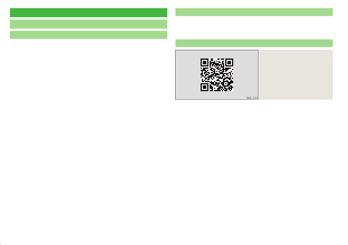
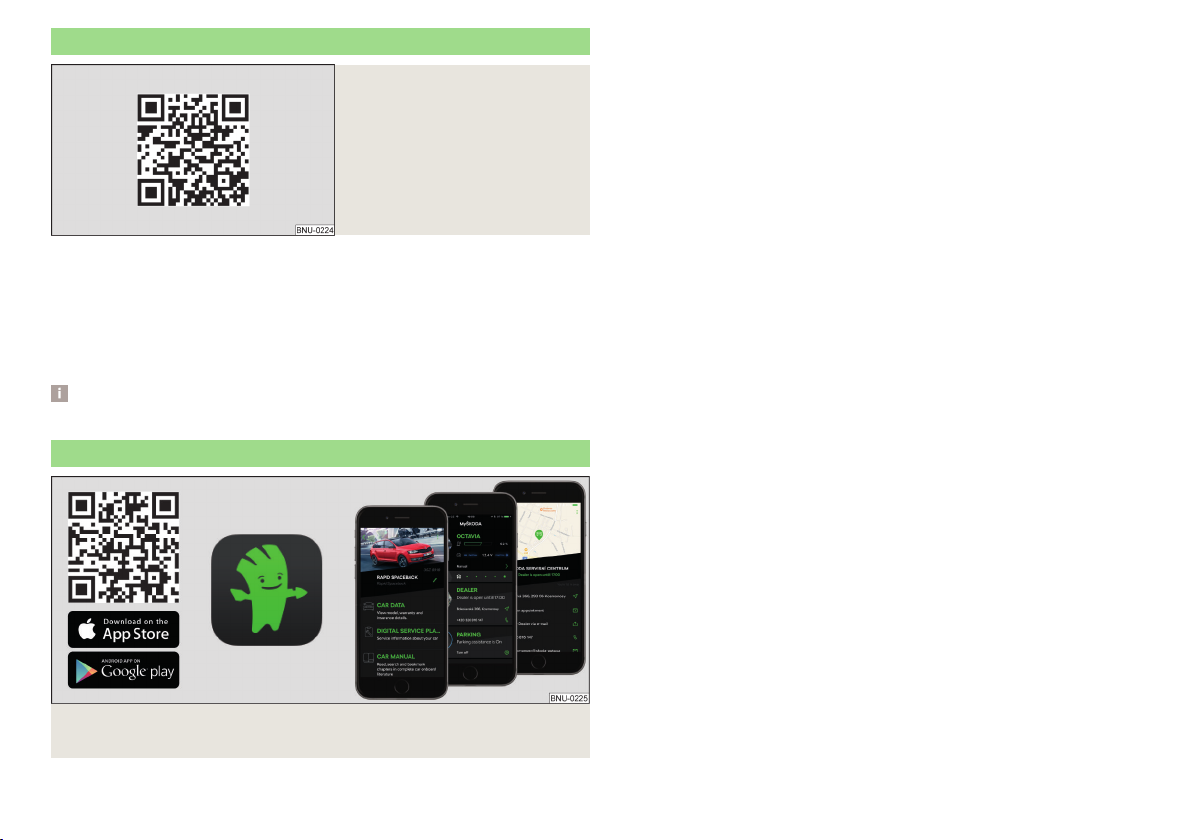
Application MyŠKODA App
The MyŠKODA App application contains, for example, the electronic version of
the Owner's Manual, quick tips regarding how to resolve certain situations in
relation to the vehicle or a description of the Simply Clever solutions.
You can use this application to get in touch with a ŠKODA partner and to use
its services or to access the breakdown service quickly.
The application can also be used as an RSS reader of favourite websites.
After entering the following address into the web browser, the website is
opened with information on the ŠKODA mobile applications.
http://go.skoda.eu/service-app
Installing the MyŠKODA App application
Scan the QR code » Fig. 4 .
›
Fig. 4 The MyŠKODA App application is available for devices with the
Android (Google) or iOS (Apple) operating system.
Introductory information
11
Page 14

Notes
Terms used
“Specialist”
“ŠKODA service partners”
“ŠKODA partners”
Text notes
“Press”
“Hold”
Direction indications
All direction indications such as “left”, “right”, “front”, “rear” relate to the forward direction of travel of the vehicle.
Explanation of symbols
→ Marker to the next operation step
Texts with this symbol draw attention to threats of a serious accident, in-
jury or loss of life.
Texts with this symbol draw attention to the risk of vehicle damage or possible
inoperability of some systems.
Texts with this symbol contain additional information.
- Workshop - a workshop that carries out specialist service tasks
for ŠKODA vehicles. A specialist can be a ŠKODA Partner, a ŠKODA
Service Partner, or an independent workshop.
- A workshop that has been contractually authorised by ŠKODA AUTO or its distribution partner to perform service work
on ŠKODA vehicles and to sell ŠKODA Genuine Parts.
- A company that has been authorised by ŠKODA AUTO or
its distribution partner to sell new ŠKODA vehicles and, when applicable,
to service them using ŠKODA Genuine Parts and sell ŠKODA Genuine
Parts.
- Short press (e.g. a button) within 1 s
- Long press (e.g. a button) for more than 1 s
WARNING
CAUTION
Note
12
About the Owner's Manual
Page 15
Online Services
ŠKODA Connect
Service package“ŠKODA Connect”
The “ŠKODA Connect” online services extend the vehicle and Infotainment
functions with the “Care Connect” and “Infotainment Online” service packages.
“ŠKODA Connect” online services are not included in the vehicle delivery. Their
order is made separately via the website “ŠKODA Connect Portal” » page 13,
Website “ŠKODA Connect Portal”. Rights and obligations of the Parties with
respect to the provision of these services are governed by a separate agreement.
“Care Connect” online services
“Care Connect” services include the following features.
▶
Emergency, information and breakdown call.
▶
Proactive service offering to connect with your ŠKODA service partner.
▶
Remote access to the vehicle using the “ŠKODA Connect” application and
the “ŠKODA Connect Portal” website.
For “Care Connect”Services functionality, the vehicle must be within range of a
mobile network through which the “Care Connect”Services are provided.
“Infotainment Online” online services
The “Infotainment Online” services extend the Infotainment functions, e.g.
with the following functions.
▶
Weather forecast.
▶
Filling station search with information on fuel prices.
▶
Online traffic information.
▶
Online destination search.
The Infotainment must be connected to the Internet for the “Infotainment
Online” Services to work» page 172.
Terms of use and availability of services
Current “conditions for the use of the user account” incl. “declaration on the
protection of personal data” can be found on the “ŠKODA Connect Portal”
website » page 13, Website “ŠKODA Connect Portal”.
The availability of the services is dependent on the type of vehicle and on the
type of Infotainment system installed in the vehicle. Some services are available only in certain countries.
Note
The availability of the services listed always refers to the period of validity of
the contract. During this interim period of validity, content changes of these
services are possible.
“ŠKODA Connect” website
Starting the ŠKODA Connect website
Fig. 5
The “ŠKODA Connect” website contains information about the online services
and their functions, access to the “ŠKODA Connect Portal” website, as well as
the option to download the “ŠKODA Connect” application.
The “ŠKODA Connect” website can be opened by scanning the QR code
» Fig. 5 or by entering the following address in your web browser.
http://go.skoda.eu/connectivity
User and vehicle registration, activation of online services
Website “ŠKODA Connect Portal”
Fig. 6 Starting the ŠKODA Connect Portal website
ŠKODA Connect
13
Page 16
The use of the “ŠKODA Connect” online services requires prior user and vehicle registration on the “ŠKODA Connect Portal” website as well as activation
of online services in the Infotainment system.
The “ŠKODA Connect Portal” website can be opened by scanning the QR code
» Fig. 6 or by entering the following address in your web browser.
http://go.skoda.eu/connect-portal
Information on registering for and activating online services
Instructional video on registration and activation of services
Fig. 7
Fig. 8 Electronic version of the instructions for registration and activa-
tion of services
Instructional video on registration and activation of services
Registration and activation are carried out in accordance with the instruction
video.
The instruction video can be opened by scanning the QR code » Fig. 7 or entering the following address into the web browser.
http://go.skoda.eu/connect-video
Electronic version of the instructions for registration and activation of
services
Current information on registration and activation of Online Services can be
found in the electronic version of the instructions for the Online Services on
the “ŠKODA Connect” website.
The electronic version of the instructions can be opened by scanning the QR
code » Fig. 8 or by entering the following address in the web browser.
http://go.skoda.eu/connect-manual
Note
For help with registration, activation as well as the Internet connection, please
contact a ŠKODA service partner.
Activation in Infotainment
Turn on the ignition and switch on Infotainment.
›
›
›
›
›
■
■
be available and the Infotainment must be connected to the Internet for activation.
■
ment.
Tap the
(Online Services)
Enter and confirm the registration PIN code received during user and vehicle
registration on the “ŠKODA Connect Portal” website.
Wait until the message
nutes)
Confirm the message.
Note
Availability of a GPS signal and a mobile network is required for activation.
In vehicles that only have “Infotainment Online” Services, a GPS signal must
The list of services can be displayed » page 15, Display of service manage-
sensor field and then the function surface →
→
Registration
.
Registration complete.
is displayed (can take several mi-
ŠKODA Connect
Deleting/switching the vehicle user
Deleting the user
Turn on the ignition and switch on Infotainment.
›
›
›
Tap the
(Online Services)
Tap the function surface
sensor field and then the function surface →
→
Registration
.
Delete owner
→
ŠKODA Connect
Delete
and confirm the delete process.
14
Online Services
Page 17
Changing the user
Turn on the ignition and switch on Infotainment.
›
›
›
›
›
By deleting the registered vehicle in the user account on the “ŠKODA Connect
Portal” website, the user is also deleted in the Infotainment system.
Tap the
(Online Services)
Tap the function surface
Enter and confirm the registration PIN code received during registration of
the new user and during vehicle registration on the ŠKODA Connect Portal
website.
If necessary, confirm the change of user by tapping the function surface
Change main users
Note
sensor field and then the function surface →
→
Registration
.
.
New owner
→
Transfer ownership
.
ŠKODA Connect
Managing online services
Display of service management
In Services Management, it is possible to display information about the online
services, the validity of their license, or to switch the services on/off.
Turn on the ignition and switch on Infotainment.
›
›
›
›
›
Tap the
line services)
To display the designations and the status of the services, select the desired service.
For detailed information about the service tap the function surface .
To switch the services on/off, tap the function surface with “Checkbox”.
sensor field and then the function surface →
→
Services Management
.
ŠKODA Connect (on-
Switch online services on/off in infotainment
Switching
By switching the
cle information and personal data, which are essential for the provision of services, are deactivated.
Tap the
›
line services)
Private mode
→
function on/off
Private mode
sensor field and then the function surface →
Services Management
function on, the services relating to sending vehi-
→
Private mode
.
ŠKODA Connect (on-
Switching “Care Connect” services on/off
By switching the “Care Connect” services off, the services relating to sending
vehicle information and personal data, which are essential for the provision of
services, are deactivated.
Tap the
›
line services)
Switching “Infotainment Online” services on/off
Tap the
›
line services)
Note
The emergency call remains fully functional after activation of the
function or after deactivation of “Care Connect” services. The functions of the
information and breakdown call are limited.
sensor field and then the function surface →
→
Services Management
sensor field and then the function surface →
→
Services Management
→
Care Connect
→
Infotainment Online
.
ŠKODA Connect (on-
ŠKODA Connect (on-
.
Private mode
Online services at ŠKODA Switch service partner off/on
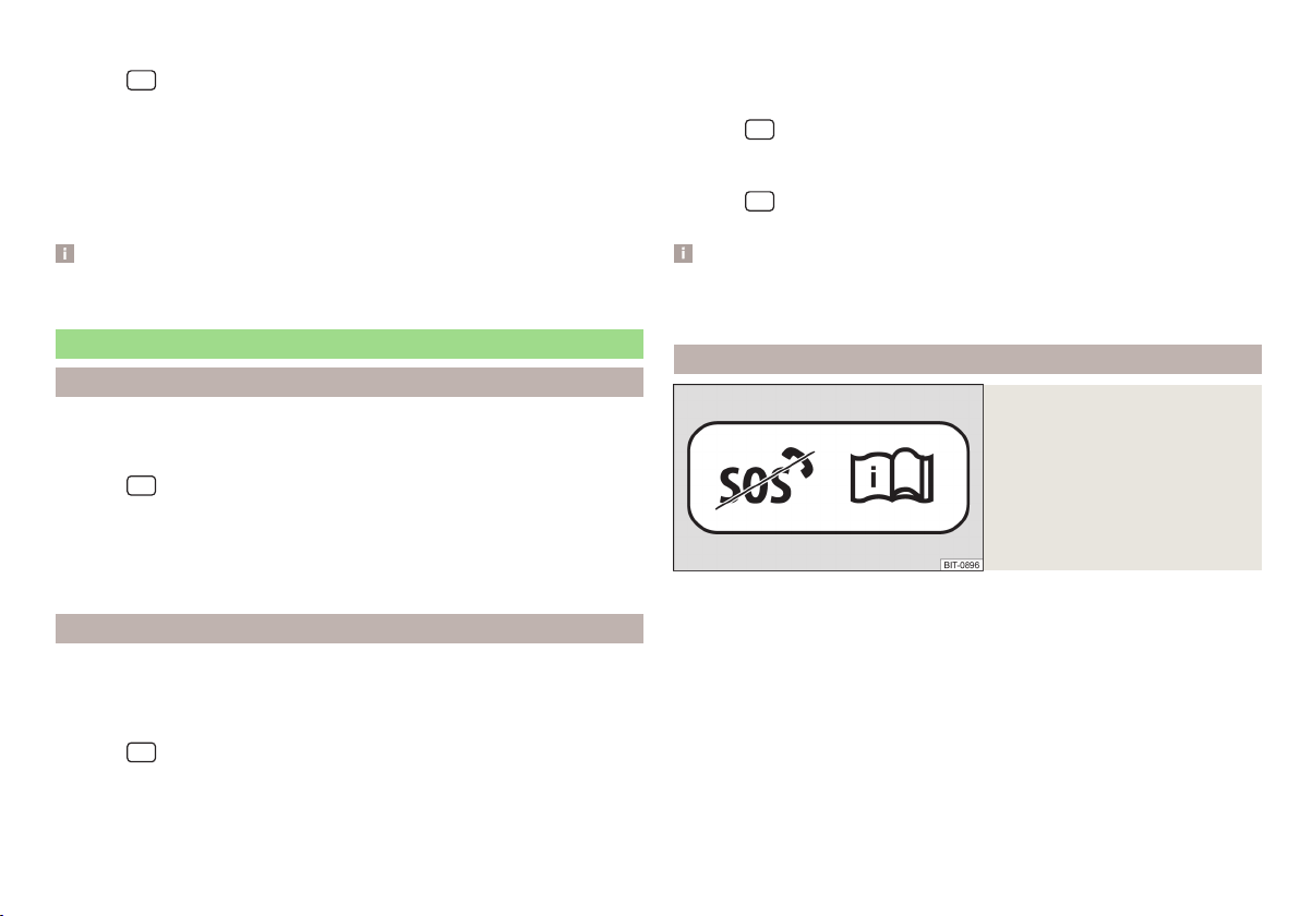
Fig. 9
Sticker with the information
about the switched off online
services
It is possible to have the online services switched off/on exclusively by a
ŠKODA service partner.
After turning off the online services, none of the “ŠKODA Connect” online
services are functioning.
To inform the vehicle user that the “ŠKODA Connect” online services, including
the emergency call are out of order, the service partner applies the the sticker
» Fig. 9 at a visible point in the vehicle (eg at the roof cladding). This Sticker
should not be removed for as long as the online services are off.
ŠKODA Connect
15
Page 18
CAUTION
It should be noted that the emergency, information and panning call is not
available after switching off the online services. For this reason, no automatic emergency call is made in the event of a serious car accident.
Status Symbols of Online Services
Fig. 10
Status symbols of online services
In the Infotainment » Fig. 10 status line, information on the status of the Online
Services is displayed.
A
The “ŠKODA Connect” online services are available. At the same time the
symbol of the connected network type can be displayed.
B
The connection to the “ŠKODA Connect” online services is being established.
C
Localisation services are restricted or disabled. Detailed information about
online services can be displayed » page 15, Display of service management.
D
Localisation services are enabled. Detailed information about online services can be displayed » page 15, Display of service management.
localisation services
For the complete functionality of some online services, activated localisation
services are required.
Localisation services include, for example, information on the last parking position, area notification or speed notification.
When localisation services are active, one of the following symbols will be displayed in the status line in the Infotainment screen
D
» Fig. 10.
Emergency call
Fig. 11 Emergency call button
Serious accident
In the event of an accident with an air bag or belt tensioner release, a call to
the emergency call centre is automatically started. The emergency call centre
simultaneously receives information on the accident, e.g. the location and severity of the accident, the number of occupants with fastened seatbelts and
the vehicle identification number (VIN).
Minor accident
The option for establishing a connection to the emergency call centre or to the
breakdown service appears in the Infotainment screen.
Manual start of a call with the emergency call centre
Press and hold the B » Fig. 11 button.
›
In the Infotainment screen or on the instrument cluster display, confirm the
›
connection setup.
The call can be started manually, for example, if you are reporting an accident
in which you were not directly involved.
The system status is displayed after the ignition is switched on, by the illumination of warning lamp
▶
Green - the system is functional.
▶
Red - there is a fault in the system.
▶
Not illumiated - the system is switched off » page 15.
Note
The emergency service is functional even without user registration and activation of services.
A
» Fig. 11.
16
Online Services
Page 19
“Care Connect” Services
Proactive service
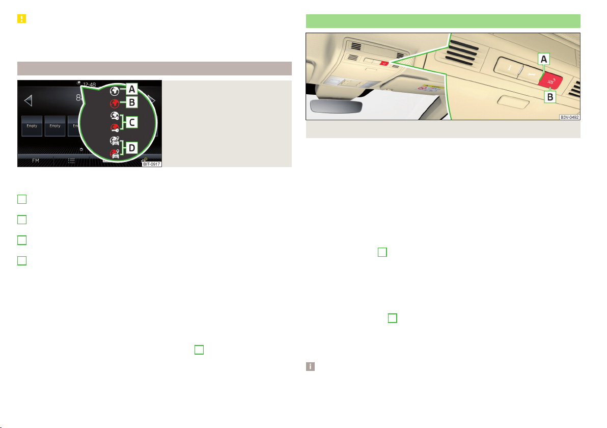
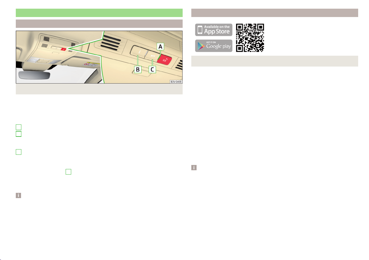
Fig. 12 Buttons and warning lights of the Care Connect services
The proactive service provides an overview of the technical status of your vehicle and on any due service events. It is also possible to establish a connection
to the information or breakdown call centre.
Buttons and warning lights of “Care Connect”services » Fig. 12
A
Warning light for system status.
B
Press this button to establish a call to the information number in the
event of problems with the online services or for information regarding
the products and services of the ŠKODA brand.
C
Press this button to establish a call to the breakdown number in the event
of a breakdown.
The system status is displayed after the ignition is switched on, by the illumination of warning lamp
▶
Green - the system is functional.
▶
Red - there is a fault in the system.
Note
The availability of the services listed always refers to the period of validity of
the contract. During this interim period of validity, content changes of these
services are possible. Current information can be found on the “ŠKODA
Connect” website» page 13.
A
» Fig. 12.
Remote access to the vehicle
Fig. 13 ŠKODA Connect application
With the remote access to the vehicle service, you can access some vehicle
functions via the “ŠKODA Connect Portal” website or the “ŠKODA Connect”
application installed on your mobile device.
After entering the following address into the web browser, the website is
opened with information on the ŠKODA mobile applications.
http://go.skoda.eu/service-app
Installing the “ŠKODA Connect” mobile application
Scan the QR code » Fig. 13 .
›
Remote access to the vehicle includes, for example, the following services.
▶
Driving data.
▶
Vehicle condition.
▶
Last parking position.
▶
Vehicle unlocking and vehicle locking.
▶
Online operation of the auxiliary heater.
Note
The availability of the services listed always refers to the period of validity of
the contract. During this interim period of validity, content changes of these
services are possible. Current information can be found on the “ŠKODA
Connect” website» page 13.
ŠKODA Connect
17
Page 20

“Infotainment Online” services
Main menu and overview of services
Applies to Infotainment Columbus, Amundsen.
Fig. 14
Main menu
These services extend the functionality of the Internet-connected Infotainment.
To display the main menu » Fig. 14, tap the
function surface .
News from the RSS channels set in the user profile on the “ŠKODA
Connect Portal” website
Online search for filling stations with information on fuel prices » page 185
Online search for car parks with information on free parking spaces
» page 185
Weather forecast near the vehicle position, the destination of the route or
in the vicinity of the selected location
Online destination search » page 183
Import of the destinations created in the user profile on the “ŠKODA
Connect Portal” website » page 189
Import of the routes created in the user profile on the “ŠKODA Connect
Portal” website » page 197
Online updating of the navigation data (valid for the infotainment Colum-
bus) and import of POI Categories » page 181
Conditions for the use of online services
Settings of Online Services » page 138
For more information on the available services, see the “ŠKODA Connect”
website» page 13.
sensor field and then tap the
Note
The availability of the services listed always refers to the period of validity of
the contract. During this interim period of validity, content changes of these
services are possible. Current information can be found on the “ŠKODA
Connect” website» page 13.
18
Online Services
Page 21

Safety
Driving safety
Passive Safety
General information
Introduction
This section of the manual includes important information on the subject of
passive safety. We have combined everything here which you should be familiar with, for example, regarding seat belts, airbags, safety of children and anything similar.
Other important safety information can also be found in the following chapters of this Owner´s Manual. The Owner´s Manual should therefore always be
in the vehicle.
Before setting off
For your own safety and the safety of the people travelling with you, please
pay attention to the following points before setting off.
▶
Check the function of the lighting and turn signal systems.
▶
Check the function of the wipers and check the wiper blades for wear.
Check the windscreen washer fluid level.
▶
Ensure that all of the windows offer good visibility to the outside.
▶
Adjust the rear-view mirror so that vision to the rear is guaranteed. Ensure
that the mirrors are not covered.
▶
Check the tyre inflation pressure.
▶
Check the engine oil, brake fluid and coolant level.
▶
Secure all items of luggage.
▶
Do not exceed the permissible axle loads and permissible gross weight of the
vehicle.
▶
Close all doors as well as the bonnet and boot lid.
▶
Ensure that no parts and components are visibly loose in the vehicle.
▶
Ensure that no objects can obstruct the pedals.
▶
Protect children by using a suitable child seat » page 29, Transporting chil-
dren safely.
▶
Adopt the correct seated position. Instruct your passengers to assume the
correct seated position » page 19, Correct and safe seating position.
In the interests of traffic safety, the following information must be observed.
▶
Do not become distracted from concentrating on the traffic situation, (e.g.
by your passengers or mobile telephone calls).
▶
Never drive when your driving ability is impaired, (e.g. due to medication, alcohol or drugs).
▶
Keep to the traffic regulations and the permissible speed limit.
▶
Always adjust the driving speed to the road, traffic and weather conditions.
▶
Take regular breaks on long journeys (at least every two hours).
Correct and safe seating position
Introduction
Always assume the correct seated position before setting off and do not
change this position while driving. Also advise your passengers to adopt the
correct seated position and not to change this position while the car is moving.
The following list contains instructions for the Passenger which, if not observed, may cause serious injuries or death.
▶
Do not lean against the dash panel.
▶
Do not put your feet on the dash panel.
The following list contains instructions for all Passengers which, if not observed, may cause serious injuries or death.
▶
Do not sit only on the front part of the seat.
▶
Do not sit facing to the side.
▶
Do not lean out of the window.
▶
Do not put your limbs out of the window.
▶
Do not put your feet on the seat cushion.
Passive Safety
19
Page 22
WARNING
■
The adjustable seats and all head restraints must be adjusted to match
the body size at all times and the seat belt must always be fastened properly to provide the most effective levels of protection to the passengers.
■
Each occupant must correctly fasten the seat belt belonging to the seat.
Children must be fastened » page 29, Transporting children safely with a
suitable restraint system.
■
The seat backrests must not be tilted too far back when driving, as this
will impair the function of the seat belts and of the airbag system – risk of
injury!
WARNING
By sitting incorrectly, the occupant is risking life-threatening injuries.
Driver’s correct seating position
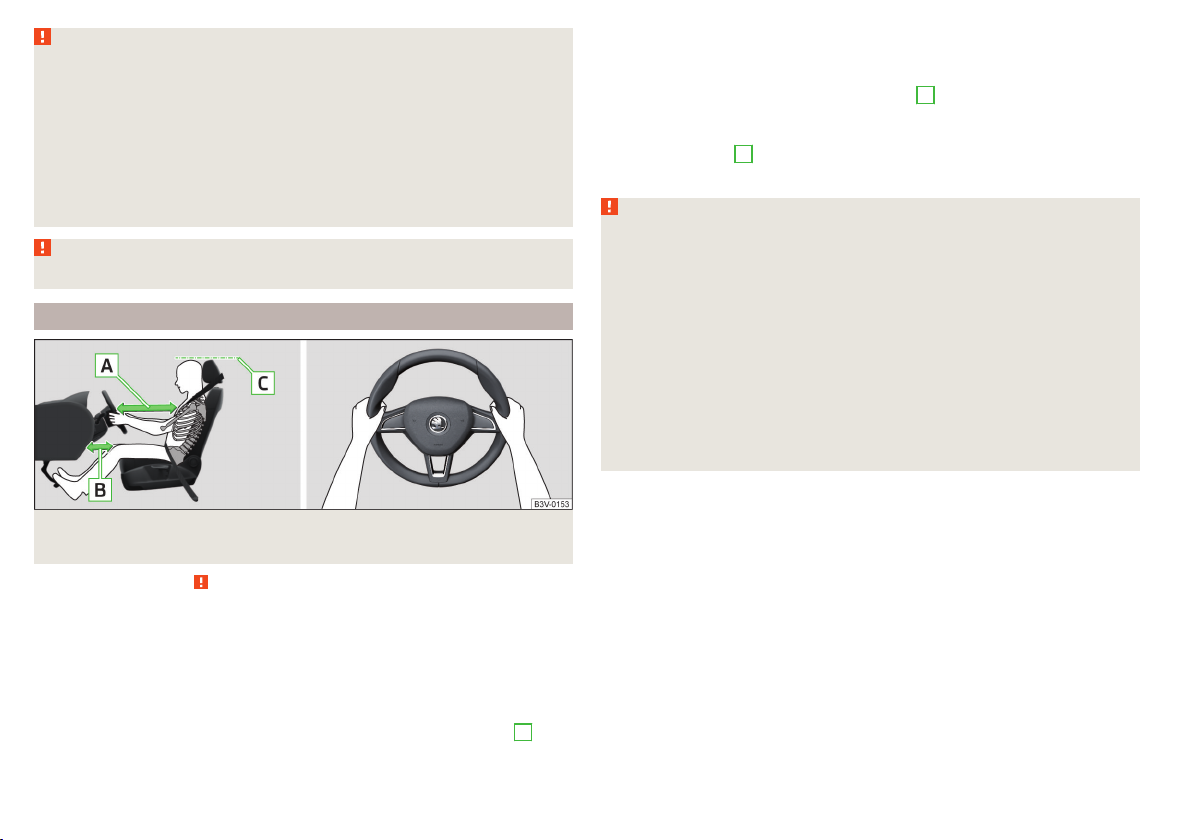
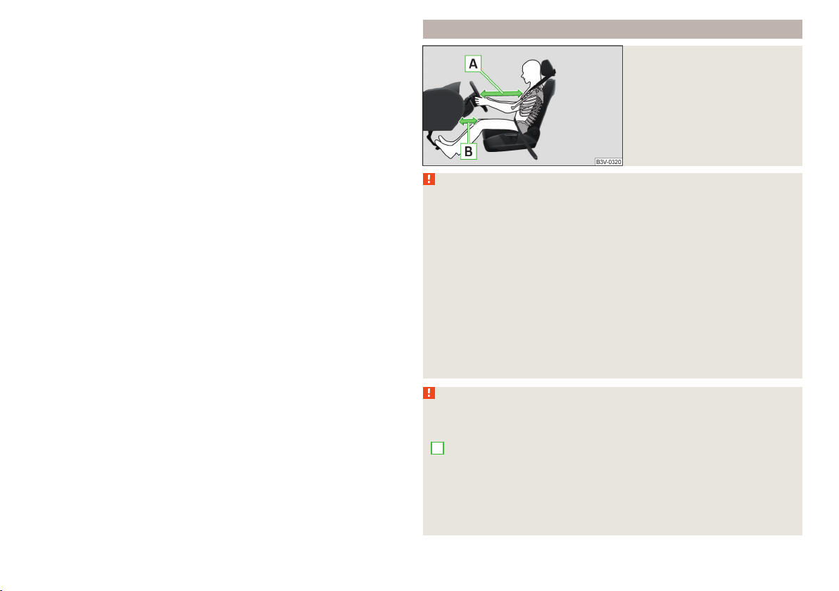
Fig. 15
Correct seated position for the driver/correct steering wheel
position
Read and observe on page 20 first.
For your own safety and to reduce the risk of injury in the event of an accident,
the following instructions must be observed.
Adjust the driver’s seat in the forward/back direction so that the pedals
can be fully depressed with slightly bent legs.
For vehicles equipped with driver knee airbags, adjust the driver's seat in a
forward/back direction so that there is a gap of at least 6 cm between the
legs and the dashboard in the vicinity of the knee airbag » Fig. 15 -
B
.
Adjust the seat backrest so that the highest point of the steering wheel
can be reached with your arms at a slight angle.
Adjust the steering wheel so that the distance between the steering wheel
and your chest is at least 25 cm » Fig. 15 - A.
Adjust the headrest so that the top edge of the headrest is at the same
level as the upper part of your head (not for seats with integrated headrests) » Fig. 15 - C.
Correctly fasten the seat belt » page 22, Using seat belts.
WARNING
■
Maintain a distance of at least 25 cm from the steering wheel, and a distance of at least 6 cm between the legs and the dash panel at the height of
the knee airbag. Not maintaining this minimum distance will mean that the
airbag system will not be able to properly protect you - hazard!
■
When driving, hold the steering wheel with both hands firmly on the outer edge in the “9 o'clock” and “3 o'clock” position » Fig. 15. Never hold the
steering wheel in the “12 o'clock” position or in any other way (e.g. in the
middle, inner edge of the steering wheel or similar). Otherwise, in the event
of airbag deployment, you could suffer serious injury to the arms, hands
and head.
■
Ensure that no objects are located in the driver's footwell, as they could
lodge in the pedal system whilst driving. You would then no longer be able
to operate the clutch, brake or acceleration pedals.
20
Safety
Page 23
Adjusting the steering wheel position
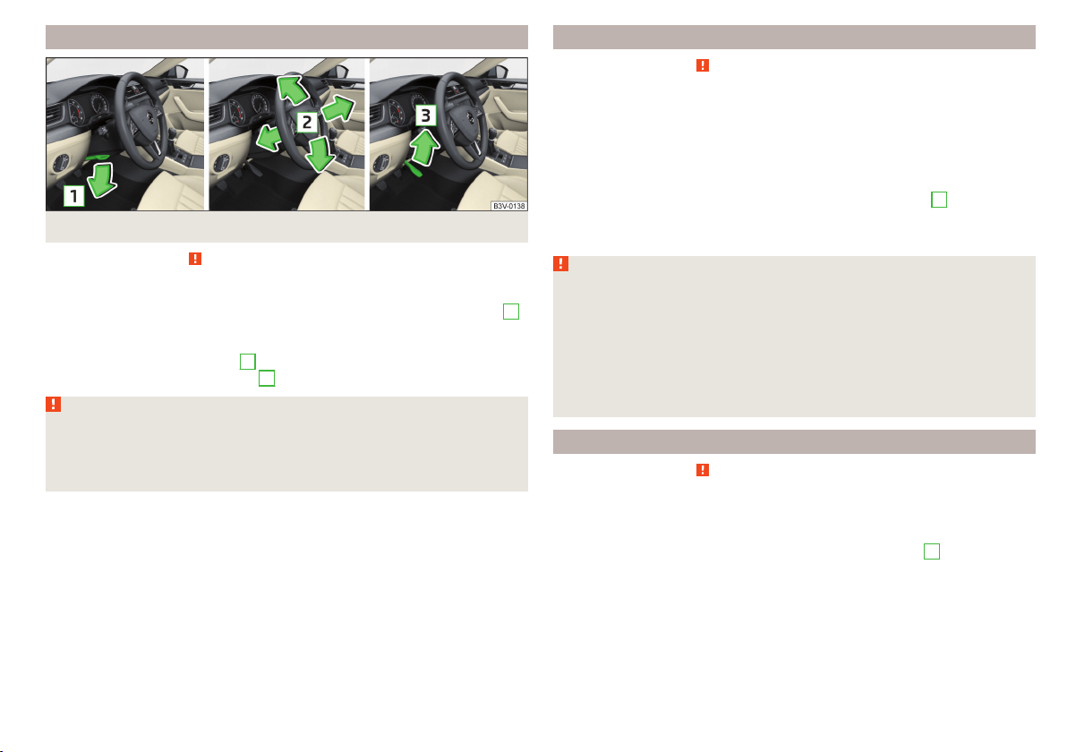
Fig. 16 Adjusting the steering wheel position
Read and observe on page 20 first.
The height and forward/back position of the steering wheel can be adjusted.
Swing the safety lever under the steering wheel in the direction of arrow
›
» Fig. 16.
Adjust the steering wheel to the desired position. The steering wheel can be
›
adjusted in direction of arrow 2.
Pull the holder in arrow direction 3 until the stop.
›
WARNING
■
Never adjust the steering wheel when the vehicle is moving only when
the vehicle is stationary!
■
The safety lever must always be locked after adjusting so that the steer-
ing wheel cannot accidentally change position – risk of accident!
Correct seating position of the passenger
Read and observe on page 20 first.
For passenger safety and to reduce the risk of injury in an accident, the following instructions must be observed.
Position the front passenger seat back as far as possible. The front pas-
senger must maintain a distance of at least 25 cm to the dash panel so
that the airbag offers the greatest possible safety if it is deployed.
Adjust the headrests so that the top edge of the headrest is at the same
level as the upper part of your head » Fig. 15 on page 20 - C (not for seats
with integrated headrests).
Correctly fasten the seat belt » page 22, Using seat belts.
WARNING
■
Ensure a distance of at least 25 cm to the dashboard, otherwise the air-
1
bag system will not be able to protect you properly - risk of death!
■
Always keep your feet in the footwell when the car is being driven – never place your feet on the instrument panel, out of the window or on the
surface of the seats! You will be exposed to increased risk of injury if it becomes necessary to apply the brake or in the event of an accident. If an airbag is deployed, you could suffer fatal injuries by adopting an incorrect
seated position!
Correct seating position for the passengers in the rear seats
Read and observe on page 20 first.
For passenger safety on the rear seats and to reduce the risk of injury in the
event of an accident, the following information must be observed.
Adjust the headrests so that the top edge of the headrest is at the same
level as the upper part of the head » Fig. 15 on page 20 -
Correctly fasten the seat belt » page 22, Using seat belts.
C
.
Passive Safety
21
Page 24
Seat belts
Using seat belts
Introduction
Seat belts that are fastened correctly offer good protection in the event of an
accident. They reduce the risk of an injury and increase the chance of survival
in the event of a major accident.
The seat belts reduce the kinetic energy considerably. They also prevent uncontrolled movements which, in turn, may well result in severe injuries.
When transporting children, observe the following information» page 29,
Transporting children safely.
WARNING
■
Put the seat belt on before starting any journey! This also applies to other
passengers - there is a danger of injury!
■
Maximum seat belt protection is only achieved if you are correctly seated
» page 19, Correct and safe seating position.
■
The seat backrests of the front seats must not be tilted too far to the rear
otherwise the seatbelts can lose their effectiveness.
WARNING (Continued)
■
Many layers of clothing and loose clothing (e. g. a winter coat over a jacket) do not allow you to be correctly seated and impairs proper operation of
the seat belts.
■
Do not attach clamps or similar objects to the belt - the function of the
belt retractor could be restricted.
■
The seat belts for the rear seats can only fulfil their function reliably when
the seat backrests are correctly locked into position » page 87.
WARNING
Information on the care and maintenance of safety belts
■
The belt webbing must always be kept clean. Soiled belt webbing may impair the proper operation of the inertia reel » page 264.
■
The seat belts must not be removed or changed in any way. Do not attempt to repair the seat belts yourself.
■
Check the condition of all the seat belts on a regular basis. If parts of the
belt system become damaged (e.g. the belt webbing, the belt connections,
the inertia reel, the locking part etc.), the respective seat belt must be replaced by a specialist garage immediately.
■
Seat belts which have been subjected to stress in an accident must be replaced by a specialist garage. Also check the seat belt anchors.
WARNING
Information on dealing with the safety belts
■
The belt webbing must not be jammed in-between at any point or twis-
ted, or chafe against any sharp edges.
■
Make sure you do not catch the seat belt in the door when closing it.
WARNING
Information on the proper use of safety belts
■
Adjust the height of the belt in such a way that the shoulder part of the
belt is roughly positioned across the middle of your shoulder - on no account across your neck.
■
No two persons (also not children) should ever use a single seat belt together.
■
The lock tongue should only be inserted into the lock which is the correct
one for your seat. Wrong use of the safety belt will reduce its capacity to
protect and the risk of injury increases.
22
Safety
Correct routing of seat belt
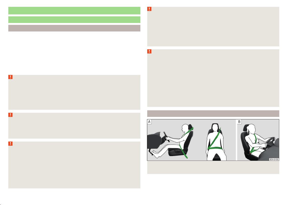
Fig. 17
Routing of belt webbing over the shoulders and the lap
belt/Routing of belt webbing for an expectant mother
Page 25
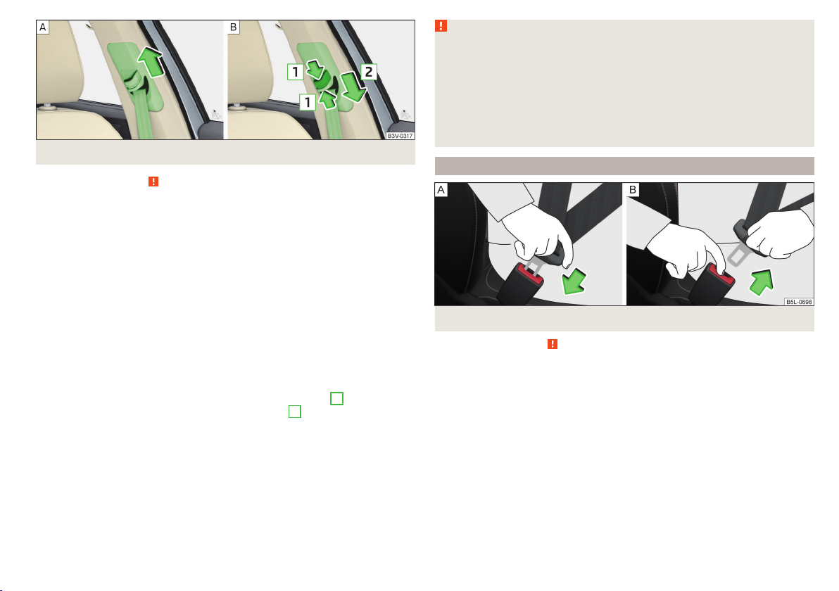
Fig. 18 Seat belt height adjusters for front seats
Read and observe on page 22 first.
It is important that the belt is properly routed to ensure seat belts offer the
maximum protection.
The shoulder part of the belt must run approximately over the middle of your
shoulder (never across your neck) and fit well against your upper body » Fig. 17
- .
The lap part of the belt must run lap part of the belt must run in front of the
pelvis (must never run across your stomach) and must always fit snugly
» Fig. 17 - .
In the case of pregnant women, the lap part of the belt must be positioned as
low as possible on the pelvis to avoid exerting any pressure on the lower abdomen » Fig. 17 - .
Seat belt height adjusters for front seats
Push the seat belt guide loop upwards in the direction of arrow» Fig. 18 - .
›
or: push together the mechanism in the direction of arrows 1 and push the
›
return pulley downwards in the direction of arrow 2 » Fig. 18 - .
Then pull firmly on the belt to ensure that the seat belt height adjuster has
›
correctly locked in place and that the belt is blocked reliably » page 24, Inertia reels.
WARNING
■
Always ensure that the webbing of the seat belts is properly routed. Seat
belts which are not correctly adjusted can themselves cause injuries even in
minor accidents.
■
A seat belt which is hanging too loose can result in injuries as your body is
moved forward by the kinetic energy produced in an accident and is then
suddenly held firm by the belt.
■
The belt webbing must not run across solid or fragile objects (e.g. spectacles, ball-point pens, keys, etc.). Such objects can cause injury.
Fastening and unfastening seat belts
Fastening/unfastening the seat belt
Fig. 19
Read and observe on page 22 first.
Before fastening
Adjust the headrest properly (does not apply to seats with integrated headr-
›
ests).
Adjusting the seat (applies to the front seats).
›
Adjust the belt height (applies to the front seats).
›
Fasten
Slowly pull the belt over the chest and pelvis.
›
Insert the lock tongue into the belt buckle for the seat » Fig. 19 - until it
›
audibly clicks into place.
Pull on the belt to check that it has engaged correctly in the lock.
›
Release
Hold the lock tongue and press the red button in the belt buckle » Fig. 19 - .
›
The lock tongue pops out.
Seat belts
23
Page 26

Feed the belt back manually so that the seat belt is not twisted and the belt
›
webbing rolls up completely.
WARNING
The slot of the belt tongue must not be blocked, otherwise the belt tongue
will not lock in place properly.
Inertia reel and belt tensioners
Inertia reels
Each seat belt is equipped with an inertia reel.
When pulling slowly on the seat belt, the belt can move freely. When pulling
sharply on the seat belt, the movement is locked by the inertia reel. The belts
also lock when full braking, when the car accelerates, when driving downhill
and when cornering.
WARNING
If the seat belt does not lock when pulling sharply on it, have the inertia reel
inspected immediately by a specialist garage.
Belt tensioners
The safety for the driver, front passenger and passengers on the outer rear
seats who are wearing their seat belts, is enhanced by the belt tensioners fitted to the inertia reels on the front and rear external seat belts.
If there is a collision with a certain severity the seat belts are tightened by the
belt tensioner so that unwanted body motion is prevented.
Belt tensioners are not activated in the event of a roll-over, minor collisions or
in accidents in which no major forces are produced.
WARNING
■
Any work on the belt tensioner system, including the removal and installation of system components because of other repair work, must only be carried out by a specialist garage.
■
If the belt tensioners have been deployed, it is then necessary to replace
the entire system.
Note
■
The belt tensioners can also be deployed if the seat belts are not fastened.
■
Smoke is generated when the belt tensioners are deployed. This is not an in-
dication of a fire in the vehicle.
Reversible belt tensioners
As part of the proactive passenger protection system, reversible seat belts increase the safety of the belted up driver and front passenger.
In critical driving situations the seat belt is tensioned tightly over the body and
then released again by the reversible belt tensioner.
Further information » page 246, Proactive occupant protection (Crew Protect
Assist).
24
Safety
Page 27
Airbag system
Description of the airbag system
Introduction
As a supplement to the seat belts, the airbag system provides additional passenger protection in the event of severe frontal and side collisions.
The best possible protective effect of the airbag can only be achieved if the
seat belts are applied properly. The airbag is not a substitute for the seat
belts.
The functional status of the airbag system is indicated by the warning light
in the instrument cluster » page 42.
System description
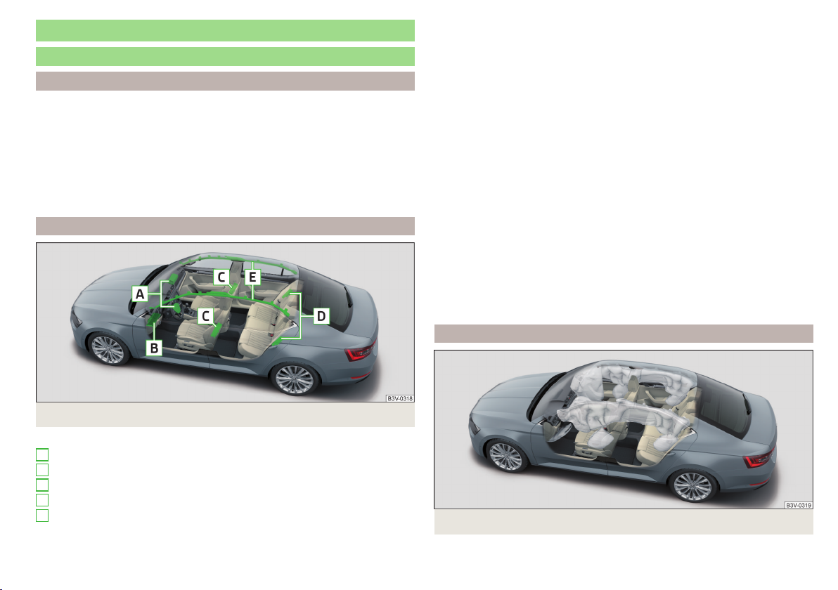
Fig. 20 Installation locations of airbags
The forward movement of the body is cushioned when it makes contact with
the fully inflated airbag and the risk of injury to the remaining body parts is
thus reduced.
▶
Front airbags - head and upper body. The airbags can be identified by the
lettering featured on the steering wheel and on the dash panel on the
passenger side.
▶
Driver's knee airbag - Legs. The airbag features the lettering on the
dashboard on the driver's side.
▶
Side airbags - for the entire upper body (chest, stomach, pelvis) on the side
next to the door. The side air bags can be identified by a label with the lettering marked on the front seat backrests. The rear side airbags are provided with the lettering in between the entrance area and the rear seat
backrest.
▶
Head airbags - head and neck. The airbags are provided with the lettering
marked on the B-pillar cladding.
Depending on the vehicle equipment, the airbag system consists of the
following parts.
▶
Individual airbags.
▶
Warning light in the instrument cluster» page 42.
▶
Key switch for the front passenger airbag » page 28.
▶
Warning light for the front passenger airbag in the middle of the dash panel
» page 28.
Airbag deployment
Installation locations of airbags » Fig. 20
A
Front airbags
B
Driver’s knee airbag
C
Front side airbags
D
Rear side airbags
E
Head airbags
Fig. 21 Inflated airbags
Airbag system
25
Page 28
The airbag system is only functional when the ignition is switched on.
When triggered, the airbag is filled with gas and unfolds. The inflation of the
airbag is carried out in a fraction of a second.
Upon inflation of the airbag, smoke is released. This is not an indication of a
fire in the vehicle.
Triggering conditions
It is not possible to generally determine which deployment conditions apply to
the airbag system in every situation. Important here is the hardness of the object on which the vehicle impacts, the impact angle, the vehicle speed, etc.
Deceleration during impact plays an important role in the deployment of the
airbags. If the vehicle deceleration which occurs and is measured remains below the prescribed reference values specified in the control unit, the airbags
are not deployed although the vehicle may well suffer severe damage to the
bodywork as a consequence of the accident.
The following airbags will be deployed in the event of a severe frontal
collision.
▶
Driver’s front airbag.
▶
Front passenger airbag.
▶
Driver’s knee airbag.
The following airbags will be deployed in the event of a severe side
collision.
▶
Front side airbag.
▶
Rear side airbag.
▶
Head airbag.
When an airbag is deployed, the following events occur.
▶
The hazard warning lights are switched on.
▶
All doors are unlocked.
▶
The fuel supply to the engine is interrupted.
▶
The interior light comes on (if the automatic operation of the interior light is
switched on - switch ).
When there is no air bag deployment?
With minor frontal and side collisions, rear collision, overturning of the vehicle
or vehicle roll-over there is no airbag deployment.
Safety instructions
Fig. 22
Safe distance from the steering
wheel and the dashboard
WARNING
General information
■
The seat belts and the airbag system can only offer proper protection
if the driver and passengers are seated properly » page 19.
■
The airbag develops considerable forces when triggered, which can lead
to serious injuries or even death if the correct seating position or seated
position is not observed. This applies in particular to children who are transported without using a suitable child safety seat » page 30.
■
If there is a fault, have the airbag system checked immediately by a specialist garage. Otherwise, there is a risk of the airbag not being activated in
the event of an accident.
■
The airbag system must be replaced if it has been deployed.
■
In the area of the front airbag and the knee airbag, the surface of the
steering wheel and the dashboard should be cleaned using only a dry cloth
or one that has been dampened with water.
WARNING
Information about front airbags
■
It is important for the driver and front passenger to maintain a minimum
distance of 25 cm from the steering wheel or the control panel » Fig. 22 -
A
, If you do not observe this distance, the airbag cannot protect you - risk
to life! The front seats and the head restraints must always be correctly adjusted to match the body size of the occupant.
■
The front passenger airbag must be deactivated if using a rear-facing
child seat on the front passenger seat » page 27, Airbag deactivation. If
this is not done, there is a risk of the child suffering severe or even fatal injuries if the front passenger airbag is deployed.
26
Safety
Page 29

WARNING (Continued)
■
No other persons, animals or objects may be positioned in front of the oc-
cupants on the front seats in the deployment area of the front air bags.
■
The steering wheel and the surface of the dashboard on the front passenger side must not have stickers attached, covered or modified in any other
way. No parts (e.g. cup holders, mobile telephone mounts etc.( should be
mounted in the vicinity of the airbag installation locations and in the airbag
deployment area.
■
Never place objects on the surface of the dashboard on the front passenger side.
WARNING
Information about knee airbags
■
Adjust the driver's seat in a forward/back direction so that there is a gap
of at least 6 cm between the legs and the dashboard in the vicinity of the
knee airbag » Fig. 22 - B. If it is not possible to meet this requirement due
to your body size, visit a specialist garage.
■
The surface of the airbag module in the lower part of the dash panel below the steering column not have stickers attached, be covered or modified in any other way. Nothing may be attached to the cover of the airbag
module or located within the immediate vicinity.
■
Do not attach any bulky and heavy objects (bunch of keys etc.) to the ignition key. These can be ejected by the knee airbag when it is deployed and
can cause injuries.
WARNING
Information about for side and head airbags
■
No objects (e.g. sun visors turned towards the windows) should be located in the deployment area of the side and head airbags. No accessories
(e.g. cup holders etc.) should be fitted to the doors - risk of injury!
■
Hang only light clothing on clothes hooks in the vehicle. Do not leave any
heavy or sharp objects in the pockets of the clothing. Do not use clothes
hangers to hang the clothing.
■
The airbag system operates using pressure sensors located in the front
doors. For this reason, no adjustments may be carried out to the doors or
door panels (e.g. installation of additional loudspeakers). Further information » page 260.
WARNING (Continued)
■
No excessive forces, such as knocks, kicks etc., should be exerted on the
seat backrests - there is a risk of damage to the side air bags. The side airbags would not be deployed in such a case!
■
Any seat or protective covers which you fit to the driver or front passenger seats must only be of the type expressly authorized by ŠKODA. In view
of the fact that the airbag inflates out of the backrest of the seat, use of
non-approved seat or protective covers would considerably impair the protective function of the side airbag.
■
Have any damage to the original seat covers or stitching at the installation point of the side airbags repaired immediately by a specialist garage.
WARNING
Information on the use of the airbag system
■
Any work on the airbag system including the installation and removal of
system components due to other repair work (e.g. removal of the seat)
must only be carried out by a specialist garage. Further information
» page 260.
■
No modifications should be made to parts of the airbag system, to the
front bumper or to the body.
■
Do not manipulate individual parts of the airbag system, as this might result in the airbag being deployed.
Airbag deactivation
Deactivating airbags
The front passenger airbag can be switched off with the key-operated switch
» Fig. 23 on page 28 - .
We recommend that you ask a ŠKODA service partner to deactivate any other
airbags.
The airbag deactivation is displayed by the warning light » page 42.
Airbag system
27
Page 30
Deactivating an airbag should be considered in cases such as the ones
below.
▶
A child seat is mounted on the front passenger seat, in which the child is
transported with its back to the direction of travel » page 29.
▶
Despite correct adjustment of the driver's seat, the distance of at least
25 cm between the middle of the steering wheel and chest cannot be maintained.
▶
Additional controls for drivers with a physical disability are installed in the vehicle.
▶
Special seats (e.g. orthopaedic seats without side airbags) are installed in the
vehicle.
WARNING
If an airbag is deactivated upon the sale of the vehicle, the buyer must be
informed of this!
Deactivating the front passenger airbag
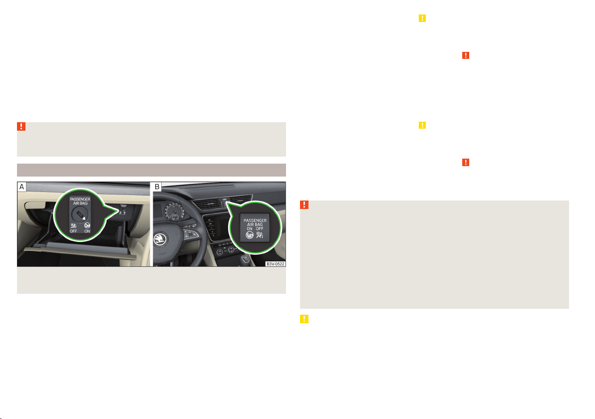
Fig. 23 Key-operated switch for the front passenger airbag / warning
light for front passenger airbag
Positions of the key switch » Fig. 23 -
The front passenger airbag is deactivated - after the ignition is switched
on, the indicator light » Fig. 23 illuminates
The front passenger airbag is activated - after the ignition is switched on,
the indicator light illuminates for 65 seconds
Switch off
Switch off the ignition.
›
Open the storage box on the front passenger's side.
›
Fold out the key bit completely» . With a KESSY key, remove the emer-
›
gency key.
Carefully insert the key into the slot in the key switch as far as the stop.
›
Use the key to turn the slot of the key switch carefully into the position .
›
Pull the key out of the slot in the key switch » .
›
Close the storage compartment on the front passenger side.
›
Check that the warning light illuminates after the ignition is switched
›
on.
Switching on
Switch off the ignition.
›
Open the storage compartment on the front passenger side.
›
Fold out the key bit completely» . With a KESSY key, remove the emer-
›
gency key.
Carefully insert the key into the slot in the key switch as far as the stop.
›
Use the key to turn the slot of the key switch carefully into the position .
›
Pull the key out of the slot in the key switch » .
›
Close the storage compartment on the front passenger side.
›
Check that the warning light illuminates after the ignition is switched
›
on.
WARNING
■
The key cannot be inserted into the key switch while driving. Shocks can
cause the key to turn in the slot and trigger the airbag! The airbag can be
triggered unexpectedly in an accident - it may result in injury or death!
■
The driver is responsible for whether the airbag is switched on or switched off.
■
Only switch off the airbag when the ignition is switched off! Otherwise a
fault can occur in the system for deactivating the airbag.
■
If the warning lights flash, the front passenger airbag will not
be deployed in the event of an accident! Have the airbag system checked
by a specialist garage immediately.
CAUTION
An insufficiently folded out key bit can damage the key switch!
28
Safety
Page 31

Transporting children safely
Child seat
Introduction
To reduce the risk of injury in the event of an accident, children must be transported in child seats!
The information in this Owner´s Manual as well as the instructions of the child
seat manufacturer must be observed when installing and using the child seat.
For safety reasons, we recommend that you always transport child seats on
the rear seats. Children should be transported on the front passenger seat only
in exceptional circumstances.
Child seats complying with the ECE-R 44 Economic Commission for Europe
standard must be used.
Child seats that comply with the ECE-R 44 standard are identified with a test
mark that cannot be removed: large E within a circle with the test number below.
WARNING
■
One should never carry children, and also not babies! - on one's lap.
■
When leaving the vehicle, do not leave children unattended in the vehicle.
Children might not be capable of leaving the vehicle or helping themselves
independently in the event of an emergency. Very high or low temperatures
can be fatal!
■
The child must be secured in the vehicle during the entire journey! Otherwise, the child would be thrown through the vehicle in the event of an accident, causing fatal injuries to both the child and other occupants.
■
Children are exposed to an increased risk of injury in the event of an accident if they lean forward or adopt an incorrect seated position when the
vehicle is moving. This particularly applies to children who are transported
on the front passenger seat as they can suffer severe, or even fatal injuries
if the airbag system is deployed!
■
Pay particular attention to the information provided by the manufacturer
of the child safety seat regarding the correct routing of the belt. Seat belts
which are not correctly adjusted can themselves cause injuries even in minor accidents.
WARNING (Continued)
■
Safety belts must be checked to ensure that they are running properly.
One should also ensure that the belt is not damaged by sharp-edged fittings.
■
When installing the child seat on the back seat, the corresponding front
seat must be adjusted so that there is no contact between the front seat
and the child seat or the child being transported in a child seat.
■
Before installing a forward-facing child seat with backrest, remove the
headrest » page 89. After removing the child seat, refit the head restraints.
Note
We recommend that you use child seats from ŠKODA Original Accessories.
These child seats were developed and also tested for use in ŠKODA vehicles.
They meet the ECE-R 44 standard.
Use of a child seat on the front passenger seat (variant 1)
Does not apply to Taiwan
Fig. 24 Warning labels
Read and observe on page 29 first.
Never use a rear-facing child restraint system on a seat which is protected
by an active airbag positioned in front of it. This could cause serious injury
to the child, even death.
Transporting children safely
29
Page 32

This is indicated also on stickers that are located at the following positions.
▶
On the front passenger's sun visor » Fig. 24 - .
▶
On the B-pillar on the front passenger side » Fig. 24 – .
The following instructions must be followed when using a child seat on the
front passenger seat.
▶
The front passenger airbag must be deactivated if using a rear-facing child
.
seat »
▶
If possible, adjust the front passenger seat backrest so that it is as vertical, so
as to ensure secure contact between the passenger seat backrest and the
back of the child seat.
▶
If possible, move the front passenger seat backwards so that there is no contact between the front passenger seat and the child seat behind it.
▶
Set the height-adjustable front passenger seat as high up as possible.
▶
Set the front passenger seat belt as high up as possible.
▶
With child safety seats in groups 2 and 3, make sure that the loop-around fittings attached to the child seat headrest is positioned in front of or at the
same height as the loop-around fittings on the B pillar on the passenger side.
Adjust the height of the front passenger seat belt so that the belt does not
“jam” in the return pulley. In the event of an accident, there is the risk of injury to the neck of the child carried due to the seat belt!
WARNING
■
Never use a rear-facing child seat on the front passenger seat if the passenger airbag is activated. This child safety seat is positioned in the deployment area of the front passenger airbag. The airbag may cause the child severe, or even fatal injuries, in the event of it being deployed.
■
As soon as the child seat, in which the child is transported with their back
in the direction of travel, is no longer used in the front passenger seat, the
front passenger airbag should be switched on again.
Use of a child seat on the front passenger seat (variant 2)
Applies to Taiwan
Fig. 25
Warning stickers
Read and observe on page 29 first.
No babies, infants or children to be carried on the passenger seat.
A sticker to this effect can also be found on the front passenger's sun visor
» Fig. 25.
Child safety and the side airbag
Fig. 26
Incorrect seated position of a
child who is not properly secured – risk from the side airbag/Child properly protected by
safety seat
Read and observe on page 29 first.
The child must not be positioned in the deployment area of the side airbag
» Fig. 26 - .
There must be sufficient room between the child and the area into which the
side airbag will deploy to allow the airbag to provide as much protection as
possible » Fig. 26 - .
30
Safety
Page 33

Classification of child seats
Read and observe on page 29 first.
Classification of child seats according to the ECE-R 44 standard.
Group Weight of the child
1 9 - 18 kg
2 15 - 25 kg
3 22-36 kg
Group Weight of the child
0 up to 10 kg
0+ up to 13 kg
Use of child safety seats which are secured using a seat belt
Never use a rear-facing child seat on the front passenger seat if the passenger airbag is activated. This child safety seat is positioned in the deployment area of
the front passenger airbag. The airbag may cause the child severe, or even fatal injuries, in the event of it being deployed.
Read and observe on page 29 first.
Overview of the usability of child seats secured with a seat belt on seats in accordance with the ECE-R 16 standard.
Group
0
up to 10 kg
0+
up to 13 kg
1
9 - 18 kg
2
15 - 25 kg
3
22 - 18 kg
a)
Set the height-adjustable front passenger seat as high up as possible.
Passenger seat with activated
front airbag
X U
X U
UF U U U
UF U U U
UF U U U
Passenger seat with deactivated
front airbag
a)
a)
Rear seats
Outside
U U
U U
U The seat is suitable for the use of approved child seats in this weight group category “Universal”.
UF The seat is suitable for the use of approved forward-facing child seats in the “Universal” weight group category.
X The seat is not suitable for children in this weight group.
Rear seat
Centre
Transporting children safely
31
Page 34

Fastening systems
attachment points of the system
Fig. 27
Labels of the system
First, remove the caps A in order to access the locking eyes» Fig. 27. After
removing the child seat, replace he caps.
WARNING
■
Always refer to the instructions of the manufacturer of the child seat
when installing and removing a child seat with the system.
■
Never attach other child seats, belts or objects to the attachment points
intended for the installation of a child seat with the system – risk of
death!
Note
■
A child seat fitted with the system can only be mounted in a vehicle fit-
ted with a system if the child seat has been approved for this type of ve-
is a system for securing child seats quickly and safely.
Two locking eyes are located between the seat backrest and the seat cushion
of the outer rear seats and front passenger seat for fixing the
system
hicle. Further information is available from a ŠKODA Partner.
■
Child seats with the system can be purchased from ŠKODA Original Ac-
cessories.
child seat in place.
Use of child safety seats with the System
Never use a rear-facing child seat on the front passenger seat if the passenger airbag is activated. This child safety seat is positioned in the deployment area of
the front passenger airbag. The airbag may cause the child severe, or even fatal injuries, in the event of it being deployed.
Overview of the usability of child seats fastened with the system on each of the seats in accordance with the ECE-R 16 standard.
32
Group
0
up to 10 kg
0+
up to 13 kg
1
9 - 18 kg
Safety
Size class of
the child seat
a)
Front passenger seat
b)
Rear seats outside Rear seat middle
E X IL X
E
X IL XD
C
D
B1
C
B
X
IL
IUF
A
X
Page 35

Group
Size class of
the child seat
2
15 - 25 kg
3
22 - 18 kg
a)
The size category is shown on the label attached to the child seat.
b)
If the front passenger seat is fitted with
system attachment points, it is suitable for the installation of an
a)
Front passenger seat
b)
Rear seats outside Rear seat middle
- X IL X
- X IL X
child seat with “Semi-Universal” approval.
IL The seat is suitable for installation of a child seat with the “Semi-Universal” approval. The “Semi-Universal” category means that the child seat with
the system is approved for your vehicle. Observe the list of vehicles that comes with the child seat.
IUF The seat is suitable for the use of approved forward-facing child seats in the “Universal” weight group category.
X The seat is not fitted with system attachment points.
Using child seats with the system
Front passenger seat Rear seats outside Rear seat middle
X i-U X
The seat is suitable for forward and backward facing child seats of
i-U
the category “Universal”.
The seat is not suitable for the child seat of the category “Universal”.
X
Attachment points of the
system
Some country-specific models can also be fitted with an attachment point
B
» Fig. 28.
WARNING
■
Always refer to the instructions from the manufacturer of the child seat
when installing and removing a child seat with the system.
■
Only use child seats with the system on the seats equipped with
attachment points with the logo .
■
Only ever attach one belt from the child seat to a locking eye.
Fig. 28
Attachment points of the
-system
is a fastening system, which restricts the movement of the upper part
of the child seat.
The locking eyes
A
for attaching the belt of a child seat with the
system are located on the rear side of the rear seat backrests » Fig. 28.
Transporting children safely
33
Page 36

Fig. 29 Cockpit example for LHD
34
Using the system
Page 37
Using the system
Cockpit
Overview
1
Electric power windows 66
2
Electric exterior mirror adjustment
3
Door opening lever 61
4
Air outlet vents 121
5
Ticket holder 92
6
Operating lever (depending on equipment):
▶
Indicator light and high-beam headlight 71
▶
Speed regulating system
▶
Speed limiter 235
▶
Headlamp assistant
7
Steering wheel with horn/with driver's front airbag
8
Buttons for operating the information system
9
Instrument cluster
10
Operating lever:
▶
Windscreen wipers and washers
▶
Information system
11
Infotainment
12
Button for hazard warning light system
13
Warning light for the front seat passenger airbag 28
14
Interior rear-view mirror 81
15
Storage compartment on the front passenger side
16
Front passenger airbag 25
17
External Infotainment module (in the passenger storage compartment)
18
Key switch for switching off the front passenger airbag (in front
passenger storage compartment)
19
Power window in the front passenger door 66
20
Storage compartment
21
Light switch 70
22
Bonnet release lever 270
23
Storage compartment 92
24
Operating lever for adaptive cruise control 239
25
Steering wheel locking lever 21
26
Depending on equipment fitted:
▶
Ignition lock
▶
Starter button
27
82
234
74
25
48
36
Depending on equipment fitted:
▶
Gearshift lever (manual gearbox)
▶
Selector lever (automatic gearbox)
28
Auto-hold button 209
29
Button for the electric parking brake 208
30
Central locking button 59
31
Bars with buttons (depending on the equipment fitted):
▶
START STOP 206
▶
Stabilisation control ESC / Traction control TCS
▶
Selection of travel mode
▶
Park Assist
▶
Parking aid
32
Storage compartment
Depending on equipment fitted:
▶
79
48
125
73
97
Phonebox
▶
12-Volt power socket
▶
Cigarette lighter
▶
Ashtrays
▶
USB input 94
33
Controls for heating/air conditioning
Note
The layout of the controls on right-hand drive vehicles differs partially from
that shown in » Fig. 29.
127
28
93
205
205
211
212
217, 218
244
229
219
93
93
100
103
102
117
Cockpit
35
Page 38

Instruments and warning lights
Instrument cluster
Introduction
Instrument cluster
Fig. 30
1
Engine revolutions counter » page 36
▶
with warning lights » page 39
2
Display » page 48
3
Speedometer
▶
with warning lights » page 39
4
Coolant temperature gauge » page 36
5
Bar with warning lights » page 39
6
Operation button
▶
Set the time » page 49
▶
Reset counter for distance travelled (trip) » page 48
▶
Displaying the distance and days until the next service interval
» page 55
7
Fuel gauge » page 37
The brightness of the instrument illumination is set automatically depending
on the ambient lighting throughout. If the visibility is poor and the lights are
not on, the brightness of the instrument lighting reduces to alert the driver to
switch on the lights in due time.
The brightness of the instrument lighting can be adjusted in Infotainment in
the menu
/ → → →
Light
.
Engine revolutions counter
The tachometer 1 » Fig. 30 on page 36 shows the actual engine speed per
minute.
The beginning of the tachometer red scale range indicates the maximum permitted speed for an engine that has been driven-in and has reached operating
temperature.
You should shift into the next highest gear before the red scale of the revolution counter is reached, or select mode D/S on the automatic gearbox.
The gear recommendation is important to note in order to maintain the optimum engine speed » page 49.
CAUTION
The pointer of the engine revolutions counter must reach the red area for only
a short time - there is a risk of engine damage!
Coolant temperature gauge
Fig. 31 Coolant temperature gauge
The display only works if the ignition is switched on.
A
Cold area, The engine has not yet reached its operating temperature.
Avoid high speeds and high engine loads.
B
The operating range
C
High temperature range, the warning light illuminates in the instrument
cluster » page 45.
36
Using the system
Page 39

Fuel gauge
Display in the rear centre console
Fig. 32 Fuel gauge
The display only works if the ignition is switched on.
The fuel tank has a capacity of about 66 litres.
If the fuel level reaches the reserve level A , the » Fig. 32 indicator light in the
instrument cluster illuminates » page 43.
WARNING
For the vehicle systems to function correctly, and thus for safe driving,
there must be sufficient fuel in the tank. Never drain the fuel tank completely – risk of accident!
CAUTION
Never drive until the fuel tank is completely empty! The irregular supply of fuel
can cause misfiring, which can result in damage to parts of the engine and the
exhaust system.
Note
The arrow next to the symbol within the fuel gauge displays the installation location of the fuel filler on the right side of the vehicle.
Fig. 33 Display in rear centre console
The following information is shown in the display depending on the equipment
installed on the vehicle.
▶
Time
▶
Exterior temperature information
▶
Information on the Climatronic set temperature for occupants in the rear
seats
Digital instrument cluster
Introduction
Fig. 34
Digital instrument panel
Instruments and warning lights
37
Page 40
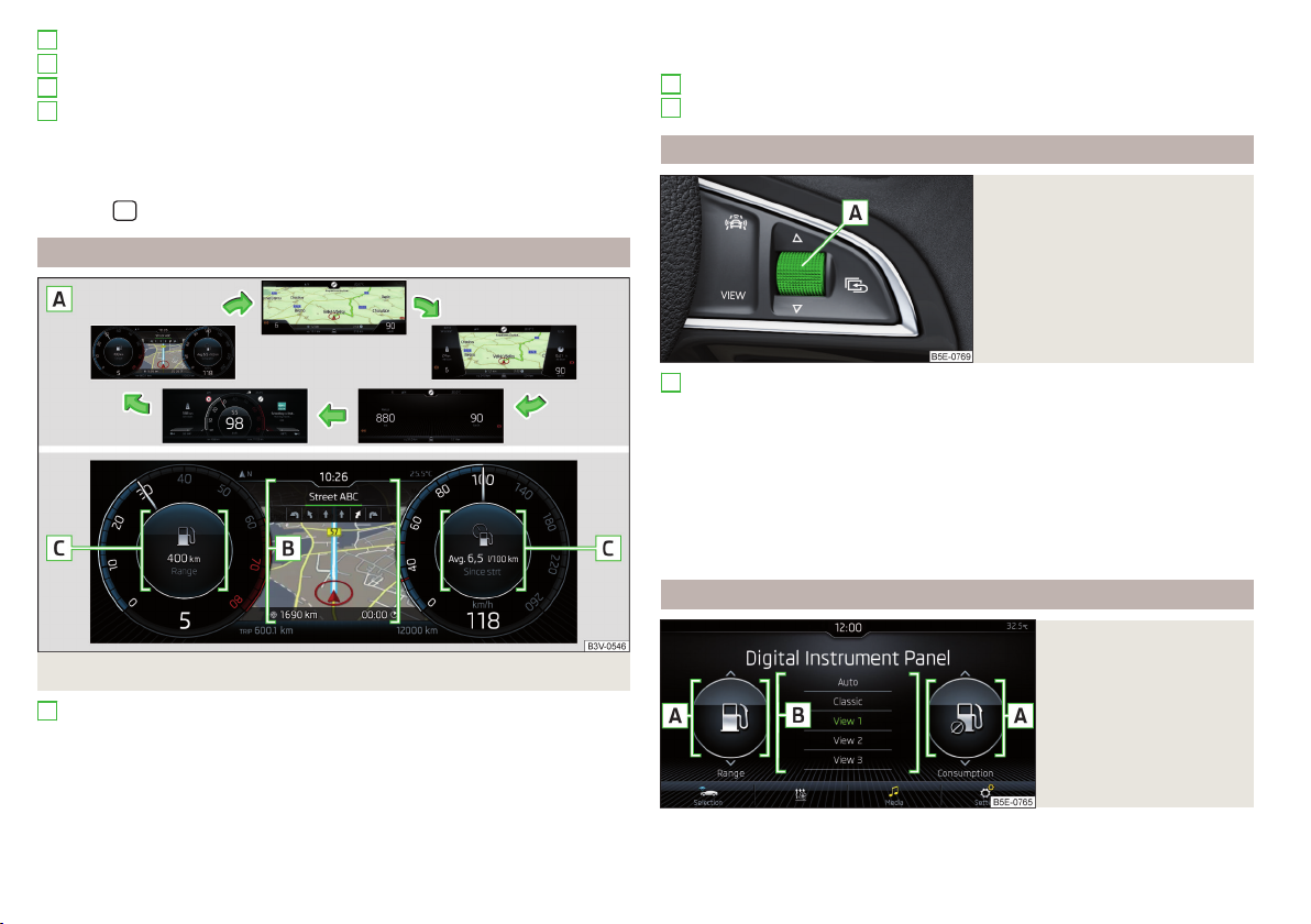
1
Bar with warning lights » page 39
2
Coolant temperature gauge » page 36
3
Display » page 38
4
Fuel gauge » page 37
The brightness of the instrument illumination is set automatically depending
on the ambient lighting throughout.
The brightness of the instrument lighting can be adjusted in Infotainment in
the menu
/ → → →
Light
.
Display in the digital instrument cluster
Fig. 35 Display versions / example of the classic display
A
Display versions (from the left)
▶
Classic display
▶
Advanced display
▶
Modern display
▶
Basic display
▶
Sporty display
B
Central display area
C
Additional information
Operating the instrument cluster
Fig. 36
Buttons/dial on the multifunction steering wheel
A
Rotate - Movement in the selected menu / setting values / Manually
change map scale (applies to Infotainment Columbus, Amundsen)
Press - confirm selected menu item
Turn and press - switch on automatic change of the map scale (applies to
Infotainment Columbus, Amundsen)
Press - Change the display version » Fig. 35 on page 38
Hold - Display the prefix options menu with additional information
Press - display main menu / return to a previous level in the menu
» page 53
pre-selection options for additional information
Fig. 37
Set the pre-selection
option in Infotainment
38
Using the system
Select the pre-selection option
Hold the button on the multi-function steering wheel.
›
Page 41

Select and confirm one of the following pre-selection options.
›
▶
Auto
- additional information is displayed depending on the driving mode se-
lected
▶
Classic
- Information on the engaged gear and the current speed
▶
View 1
- adjustable pre-selection option
▶
View 2
- adjustable pre-selection option
▶
View 3
- adjustable pre-selection option
Set the preselection option
The area code options
the menu
▶
The desired additional information can be selected by moving your finger
/ in the →
View 1. View 2
and
Dig. Instrument cluster
View 3
can be found in infotainment in
menu item.
vertically across the display in the A » Fig. 37 areas.
▶
Hold the desired function surface for the preselection option in area B to
save the selection.
Warning lights
Introduction
Parking brake » page 40
Brake system » page 40
Front seat belt warning light » page 40
Adaptive Cruise Control (ACC) » page 40
Power steering
Steering lock (KESSY system)
Stabilisation control (ESC)
Traction control (TCS)
Traction control (ASR) deactivated » page 42
Antilock brake system (ABS) » page 42
Rear fog light » page 42
Exhaust control system » page 42
Glow plug system (diesel engine) » page 42
EPC fault light (petrol engine) » page 42
Safety systems » page 42
Tyre pressure » page 43
» page 41
» page 41
Brake pads » page 43
Fuel reserve » page 43
Lane Assist » page 44
Turning signal system » page 44
Trailer turn signal lights » page 44
Fog lights » page 44
Speed regulating system
Speed limiter
» page 44
Brake pedal (automatic gearbox) » page 44
Auto Hold function » page 44
High beam » page 44
Automatic gearbox » page 44
Rear seat belt warning light » page 45
Alternator » page 45
Coolant » page 45
Engine oil pressure » page 45
Engine oil level » page 45
AdBlue® level too low (diesel engine) » page 46
AdBlue® error (diesel engine) » page 46
Bulb failure » page 46
Display when the light is switched off » page 46
Particle filter » page 46
Windscreen washer fluid level » page 47
Headlamp assistant » page 47
START-STOP system » page 47
Display of a low temperature » page 47
Water in fuel filter (diesel engine) » page 47
Adaptive Cruise Control (ACC) » page 47
Distance warning (Front Assist) » page 47
Front Assist » page 47
Emergency call » page 47
Economy mode » page 48
Instruments and warning lights
39
Page 42

Adaptive chassis (DCC) » page 48
Service » page 48
The warning lights in the instrument cluster indicate certain functions or faults.
Some warning lights can be accompanied by acoustic signals and messages in
the display of the instrument cluster.
After switching on the ignition, some warning lights light up briefly as a func-
tion test. If the tested systems are OK, the corresponding warning lights go
out a few seconds after switching on the ignition or after starting the engine.
Warning lights in the display
Depending on the significance, the warning light (danger) or (warning) illuminates along with some other warning lights in the display.
Depending on vehicle equipment fitted, some indicator lights can be shown in
the display. For example. the coolant warning light can be shown as follows.
▶
- monochrome (“black and white”) display
▶
- coloured display
WARNING
■
Ignoring illuminated warning lights and related messages or instructions
in the display of the instrument cluster may lead to serious personal injury
or damage to the vehicle.
■
If you have to stop for technical reasons, then park the vehicle at a safe
distance from the traffic, switch off the engine and switch on the hazard
warning lights » page 73. Place the warning triangle at the prescribed distance.
■
The engine compartment of your car is a hazardous area. While working
in the engine compartment, be sure to observe the following warnings
» page 269.
Parking brake
Read and observe on page 40 first.
illuminates - the parking brake is switched on.
Parking brake error
illuminates
Message:
Fault: electronic parking brake
▶
Seek help from a specialist garage.
Parking on a slope that is too steep
illuminates
Message:
▶
Find a parking space on a flat surface or on a slope that is not so steep.
Parking brake: Gradient too steep. Log book!
Brake system
Read and observe on page 40 first.
lights up – the brake fluid level in the brake system is too low.
▶
Stop the vehicle, switch off the engine, and check the level of the brake fluid
» page 273.
WARNING
■
If warning light illuminates simultaneously with warning light
» page 42, Anti-lock braking system (ABS) , stop driving! Seek help
from a specialist garage.
■
A fault to the ABS system or the braking system can increase the vehicle's braking distance – risk of accident!
Front seat belt warning light
Read and observe on page 40 first.
illuminates - the driver or front passenger has not fastened their seat belt.
At a speed of more than approximately 30 km/h, the warning light flashes
and an audible warning sounds at the same time.
If the seat belt is not fastened by the driver or front passenger during the next
approx. 2 minutes, the warning signal is deactivated and the warning light
illuminates permanently.
Adaptive cruise control (ACC)
Read and observe on page 40 first.
illuminates – the ACC delay is not sufficient.
▶
Apply the brake.
40
Using the system
Page 43

For more information about the ACC system » page 236.
Power steering/steering lock (KESSY system)
Read and observe on page 40 first.
Fault in the power steering
lights up – this indicates a complete failure of the power steering and the
steering assist is no longer working (significantly higher steering forces).
illuminates - this indicates a partial failure of the power steering and the
steering forces may be greater.
▶
Switch off the ignition, start the engine again and travel a short distance.
▶
If the warning light does not go off, stop the vehicle, do not continue
your journey. Seek help from a specialist garage.
▶
If the warning light does not go off, you can drive on, exercising appropriate caution. Seek assistance from a specialist garage immediately.
Steering lock defect (KESSY system)
flashes
Message:
▶
Park the vehicle, and stop driving. After switching off the ignition, it is no
longer possible to lock the steering, to activate the electrical components
(e.g. Infotainment ), to switch on the ignition again and to start the engine.
Seek help from a specialist garage.
flashes
Message:
▶
You can drive on, exercising appropriate caution. Seek assistance from a specialist garage immediately.
Steering column lock not unlocked (System KESSY)
flashes
Message:
▶
Move the steering wheel slightly back and forth, thereby facilitating unlocking the steering lock.
▶
If the steering does also not unlock then, the help of a specialist garage is required.
Steering lock faulty. Stop!
Steering lock: workshop!
Steering lock: workshop!
Disconnecting the vehicle battery
If the vehicle's battery has been disconnected and reconnected, the indicator
light comes on after switching on the ignition.
The warning light should go out after driving a short distance.
If, after the motor is restarted and a short drive, the indicator light does not go
out, there is a system error.
▶
You can drive on, exercising appropriate caution. Seek assistance from a specialist garage immediately.
Stability Control (ESC)/Traction control (TCS)
Read and observe on page 40 first.
flashes – the ESC or TCS is currently being activated.
illuminates – there is an ESC or TCS fault.
▶
You can drive on, exercising appropriate caution. Seek assistance from a specialist garage immediately.
If the warning light comes on after starting the engine, the TCS may be
switched off for technical reasons.
▶
Switch the ignition off and on again.
If the warning light does not illuminate after you switch the engine back on,
the TCS is fully functional again.
Disconnecting the vehicle battery
If the vehicle's battery has been disconnected and reconnected, the indicator
light comes on after switching on the ignition.
The warning light should go out after driving a short distance.
If, after a short drive, the indicator light does not go out, there is a system er-
ror.
▶
You can drive on, exercising appropriate caution. Seek assistance from a specialist garage immediately.
For more information on the ESC system » page 217 or TCS system
» page 218.
Instruments and warning lights
41
Page 44

Traction control (TCS) deactivated
Read and observe on page 40 first.
illuminates – the TCS system is disabled.
Anti-lock braking system (ABS)
Read and observe on page 40 first.
lights up – there is an ABS fault.
The vehicle will only be braked by the normal brake system without the ABS.
▶
You can drive on, exercising appropriate caution. Seek assistance from a specialist garage immediately.
WARNING
■
If warning light illuminates simultaneously with warning light
» page 40, Brake system , stop driving! Seek help from a specialist
garage.
■
A fault to the ABS system or the braking system can increase the vehicle's braking distance – risk of accident!
Rear fog light
Read and observe on page 40 first.
illuminates - the rear fog light is switched on.
Emission control system
Read and observe on page 40 first.
illuminates – there is a fault in the emission control system. The system
makes it possible to drive on in emergency mode – there may be a noticeable
reduction in engine performance.
▶
You can drive on, exercising appropriate caution. Seek assistance from a specialist garage immediately.
Preheating unit (diesel)
Read and observe on page 40 first.
flashes – there is a fault in the engine management system. The system
makes possible operation emergency mode - there may be a noticeable reduction in engine performance.
There is a fault in the glow plug system if the warning light does not come
on or illuminates continuously.
▶
You can drive on, exercising appropriate caution. Seek assistance from a specialist garage immediately.
EPC warning light (petrol)
Read and observe
lights up – there is a fault in the engine management system. The system
makes it possible to drive on in emergency mode – there may be a noticeable
reduction in engine performance.
▶
You can drive on, exercising appropriate caution. Seek assistance from a specialist garage immediately.
Safety systems
Read and observe on page 40 first.
System fault
illuminates
Message:
▶
Seek help from a specialist garage.
The front passenger airbag has been disabled with the key switch
illuminates for 4 seconds after the ignition has been switched on.
One of the airbags or a belt tensioner has been disabled by the diagnostic
tool
lights up for around 4 seconds after the ignition is switched on and then
flashes for approximately 12 seconds
Message:
Error: airbag
Airbag/ belt tensioner deactivated.
on page 40 first.
42
Using the system
Page 45

ProActive passenger protection
illuminates and the following message is shown in the information cluster
display
Proactive passenger protection unavailable.
Message:
or
ProActive passenger protection: funct. restricted.
The seat belt for the driver and front passenger needs to be replaced.
▶
Seek help from a specialist garage.
WARNING
When a fault in the airbag system occurs, there is a risk of the system not
being triggered in the event of an accident. Therefore, this must be
checked immediately by a specialized garage.
Tyre pressure
Read and observe on page 40 first.
Change of tyre pressure values
illuminates - there was a pressure change in one of the tyres.
▶
Immediately reduce speed and avoid sudden steering and braking manoeuvres.
▶
Stop the vehicle, turn the ignition off and check the tyres and their inflation
pressures » page 277.
▶
Correct the tyre pressure if necessary or replace the affected wheel
» page 283 or use the repair kit » page 286.
▶
Save the tyre pressure values in the system » page 253.
System fault
flashes for approximately 1 minute and remains lit – there may be a fault in
the tyre pressure monitoring system.
▶
Stop the vehicle, turn the ignition off and start the engine again.
If the warning light flashes after starting the engine again, there is a system
error.
▶
You can drive on, exercising appropriate caution. Seek assistance from a specialist garage immediately.
Disconnecting the vehicle battery
If the vehicle's battery has been disconnected and reconnected, the indicator
light comes on after switching on the ignition.
The warning light should go out after driving a short distance.
If, after a short drive, the indicator light does not go out, there is a system er-
ror.
▶
You can drive on, exercising appropriate caution. Seek assistance from a specialist garage immediately.
Other incidents
The illumination of the warning light can have the following reasons.
▶
The vehicle is loaded on one side. Distribute the load evenly.
▶
The wheels of one axle are loaded more heavily (e.g. when towing a trailer or
when driving uphill or downhill).
▶
Snow chains are mounted.
▶
A wheel has been changed.
CAUTION
Under certain circumstances (e.g. sporty style of driving, wintry or unpaved
roads) the warning light can be delayed or does not light up at all.
Brake linings
Read and observe on page 40 first.
illuminates - the brake pads are worn.
▶
It is possible to continue driving with due caution. Seek assistance from a
specialist garage immediately.
Fuel reserve
Read and observe on page 40 first.
illuminates – the fuel level in the fuel tank is at the reserve level (approxi-
mately 6 litres).
▶
Fill up with fuel » page 265.
Note
The text in the display goes out after refuelling and driving a short distance.
Instruments and warning lights
43
Page 46

Lane Departure Warning (Lane Assist)
Read and observe on page 40 first.
The warning lights indicates the state of the Lane Assist system.
More information about the Lane Assist System » page 247.
Turn signal system
Read and observe on page 40 first.
flashes - the left turn signal is switched on.
flashes – the right turn signal is turned on.
If there is a fault in the turn signal system, the warning light flashes at twice its
normal rate (does not apply when towing).
When the hazard warning light system is switched on, this will cause all of the
turn signal lights as well as both warning lights to flash.
Trailer turn signal lights
Read and observe on page 40 first.
flashes - the trailer turn signals are switched on.
If a trailer is hitched and the warning light is not flashing, one of the trailer
turn signal lights has failed.
▶
Check the trailer bulbs.
Fog lights
Read and observe on page 40 first.
illuminates - the fog lights are switched on.
Speed regulating system/speed limiter
Read and observe on page 40 first.
illuminates - the vehicle speed is limited by the speed regulating system
and/or the adaptive cruise control or by the speed limiter.
flashes - the speed set with the speed limiter has been exceeded.
Brake pedal (automatic gearbox)
Read and observe on page 40 first.
lights up – apply the brake.
Auto Hold function
Read and observe on page 40 first.
illuminates - the Auto Hold function is activated.
For more information about the Auto-Hold Function » page 209.
Main beam
Read and observe on page 40 first.
illuminates - the main beam or headlight flasher is switched on.
Automatic gearbox
Read and observe on page 40 first.
Gearbox overheated
illuminates
Message:
Transmission overheated. You can drive on, exercising appropriate caution.
illuminates
Message:
▶
Do not drive the vehicle! Stop the vehicle and turn off the engine.
You can continue your journey as soon as the warning light disappears.
▶
If the warning light does not go off, stop driving! Seek help from a specialist garage.
Transmission problem
illuminates
Message:
Gearbox overheated. You can drive on.
Gearbox overheated. Stop! Log book!
Gearbox faulty. Stop the vehicle safely!
44
Using the system
Page 47

illuminates
Message:
▶
You can drive on, exercising appropriate caution. Seek assistance from a specialist garage immediately.
Gearbox in emergency mode. No reverse gear.
Error: gearbox. Speed is limited.
Rear seat belt warning light
Read and observe on page 40 first.
illuminates – a rear seat belt is not fastened.
illuminates - a rear seat belt is fastened.
When the seat belt is fastened/unfastened, the particular light lights up briefly
and indicates the current belt status!
Generator
Read and observe on page 40 first.
illuminates - the battery is not being charged while the engine is running.
CAUTION
If in addition to the light the light lights up while driving, stop driving There is a risk of engine damage! Switch off the engine and seek assistance
from a specialist garage.
Coolant
Read and observe on page 40 first.
Coolant level too low
illuminates
Message:
▶
Stop the vehicle, switch off the engine and let it cool.
▶
Check the coolant level » page 272.
If the coolant level is within the specified range and the warning light lights
up again, then there may be a malfunction of the cooling fan.
Please check the coolant level. Log book!
▶
Switch off the ignition.
▶
Check the fuse for the radiator fan, replace if necessary.
If the coolant level and fan fuse are both OK but the warning lightlights up
again, stop driving!
▶
Seek help from a specialist garage.
Coolant temperature too high
illuminates
Message:
▶
▶
▶
▶
▶
If it is not possible to top up with engine oil, stop driving - there is a risk of
engine damage! Switch off the engine and seek assistance from a specialist
garage.
Engine oil level too low
illuminates
Message:
▶
Engine overheat. Stop! Observe log book.
Stop the vehicle, switch off the engine and let it cool.
Continue your journey only after the warning light has disappeared.
Engine oil pressure
Read and observe on page 40 first.
flashes - the engine oil pressure is too low.
Stop the vehicle, switch off the engine, and check the engine oil level.
Even if the oil level is correct, do not drive any further if the warning light
is flashing! Also do not leave the engine running at an idling speed.
Seek help from a specialist garage.
CAUTION
Engine oil level
Read and observe on page 40 first.
Please add engine oil.
Stop the vehicle, switch off the engine, and check the engine oil level, top up
if necessary.
Instruments and warning lights
45
Page 48

The warning light will go out if the bonnet is left open for more than 30 seconds. If the engine oil is not replenished, the warning light will come on again
after driving about 100 km.
Engine oil level too high
illuminates
Message:
▶
Stop the vehicle, switch off the engine, and check the engine oil level.
▶
In the event of an oil level which is too high, you can drive on, exercising appropriate caution. Seek assistance from a specialist garage immediately.
Fault on the engine oil level sensor
illuminates
Message:
▶
Immediately drive to the nearest specialist garage with appropriate caution.
If it is not possible to top up with engine oil, stop driving - there is a risk of
engine damage! Switch off the engine and seek assistance from a specialist
garage.
Illuminates - AdBlue®level too low.
▶
Replenish Add AdBlue® » page 267.
▶
Seek help from a specialist garage.
illuminates - one of the lamps is faulty.
Please reduce oil level.
Oil sensor: please visit workshop.
CAUTION
AdBlue®level II low (diesel engine)
Read and observe on page 40 first.
AdBlue® error (diesel engine)
Read and observe on page 40 first.
illuminates – there is a fault in the AdBlue® system.
Lamp failure
Read and observe on page 40 first.
A message will appear in the display about the affected lamp.
Display when the light is switched off
Read and observe on page 40 first.
Applies to vehicles with the digital instrument cluster.
lit - no light is on.
Message:
The particulate filter separates and burns the soot particles from the exhaust.
To clean the filter, if allowed by the traffic conditions » , you should drive at a
speed between 50-120 km/h in the recommended gear.
If the filter is properly cleaned, the warning light extinguishes.
If the indicator light does not go out within 30 minutes, the filter was not
cleaned.
▶
Immediately drive to the nearest specialist garage with appropriate caution.
■
rain and traffic conditions.
■
ard and serious injury could be caused. Therefore, never stop the vehicle at
places where the underside of your vehicle can come into contact with
flammable materials, such as dry grass, undergrowth, leaves, spilled fuel or
the like.
■
As long as the warning light illuminates, one must take into account an
increased fuel consumption and a power reduction of the engine.
■
As long as the indicator light is lit, the START-STOPfunction is not availa-
ble.
Please turn on the light.
Particulate filter
Read and observe on page 40 first.
illuminates - the filter is clogged with soot.
WARNING
Always adjust the speed and driving style to the actual weather, road, ter-
The particulate filter reaches very high temperatures - there is a fire haz-
CAUTION
46
Using the system
Page 49

Note
We encourage you to avoid constant short journeys. This supports the correct
function of the particulate filter.
Windscreen washer fluid level
Read and observe on page 40 first.
illuminates - the windscreen washer fluid level is too low.
▶
Top up the windscreen washer fluid » page 271.
Headlight assistant
Read and observe on page 40 first.
Illuminates – the headlight assistant is activated » page 74, Headlight Assist (Light Assist / Dynamic Light Assist).
START-STOPsystem
Read and observe on page 40 first.
The warning lights indicates the state of the START STOP system
» page 206.
Display of a low temperature
Read and observe on page 40 first.
illuminates - the outside temperature is below +4 °C.
WARNING
Even at temperatures around +4 °C, black ice may still be on the road surface! Do not only rely upon the information given on the outside temperature display that there is no ice on the road.
If too much water is present in the separator, the following information appears on the instrument cluster display.
illuminates
Message:
▶
The warning lights indicate the condition of the ACC system
» page 236.
mum.
Information on the Front Assist system» page 242.
▶
▶
▶
Illuminates with the lettering - Front Assist is deactivated » page 243.
Water in fuel filter. Log book!
You can drive on, exercising appropriate caution. Seek assistance from a specialist garage immediately.
Adaptive Cruise Control (ACC)
Read and observe on page 40 first.
Front Assist
Read and observe on page 40 first.
illuminates – the safe distance to the vehicle in front is below the mini-
front Assist
Read and observe on page 40 first.
illuminates
Front Assist has recognised the risk of a collision or automatically triggered
an emergency braking manoeuvre » page 242.
An automatic deactivation of Front Assist took place when activating ESC
Sport » page 217 and when deactivating the ASR » page 218.
Front Assist is not available » page 244.
Water in the fuel filter (diesel engine)
Read and observe on page 40 first.
The fuel filter with water separator, filters out dirt and water from the fuel.
emergency call
Read and observe on page 40 first.
lights up – there is a fault in the emergency call system.
▶
Seek help from a specialist garage.
Instruments and warning lights
47
Page 50
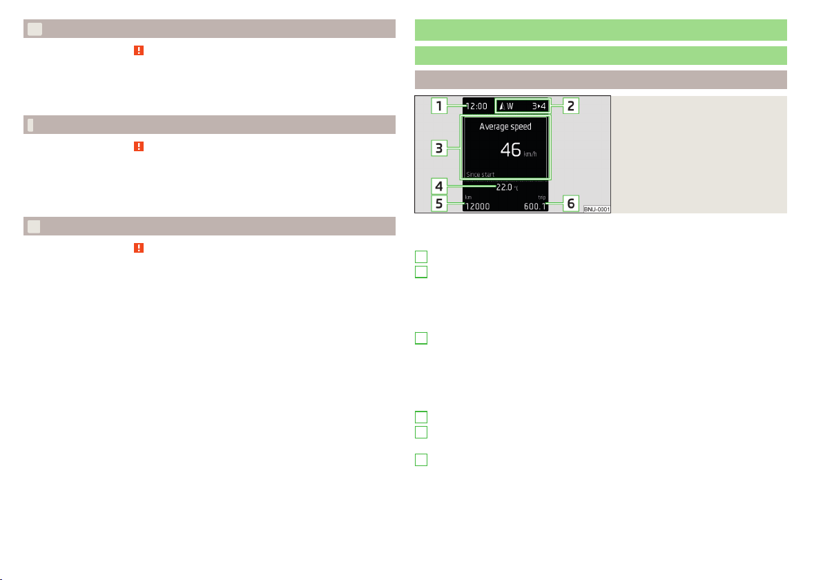
Economy mode
Read and observe on page 40 first.
illuminates - the vehicle is in economy mode due to the intervention of the
active cylinder management or due to the neutral position of the automatic
gearbox.
Adaptive chassis (DCC)
Read and observe on page 40 first.
illuminates – there is a DCC fault.
▶
It is possible to continue driving with due caution. Seek assistance from a
specialist garage immediately.
Information system
Driver information system
Display in the instrument cluster
Fig. 38
Display overview
Service
Read and observe on page 40 first.
illuminates – note regarding a due service appointment » page 55, Display-
ing the distance and days until the next service interval.
48
Using the system
Depending on the vehicle's equipment, the information system uses the display in the instrument cluster to provide the following information » Fig. 38.
1
Time / symbols of the Infotainment voice control
2
Engaged gear / gear recommendation
Selector lever positions for the automatic gearbox
Warning lights of the START-STOP system
Compass display
Detected traffic signs
3
Driving data (multifunction display)
Warning lights
Information messages
Door alarm
Eco tips
Service interval display
4
Outside temperature
5
Cruise control / speed limiter
Total distance travelled
6
Distance travelled by resetting the memory (trip)
Door, luggage compartment and bonnet alarm
When the door or luggage compartment / bonnet is open, a graphic warning
appears in the display.
Page 51

An acoustic signal will also sound if you drive the vehicle above 6 km/h when a
door is open.
Reset counter for distance travelled (trip)
Press button A » Fig. 39 on page 49.
›
Setting the time
Fig. 39
Button in the instrument cluster
Set the time using the button in the instrument cluster
Switch on the ignition.
›
Press and hold the buttonA » Fig. 39until the
›
Release the button A and the system switches to the hour setting function.
›
Press the button A again and set the hours.
›
Wait 4 seconds, the system switches to the minutes setting.
›
Press the button A again and set the minutes.
›
Wait 4 seconds, the system switches to the initial setting.
›
time
is shown in the display.
Gear recommendation
Fig. 40
Information on the selected
gear / Gear recommendation
Display » Fig. 40
Optimal gear engaged
Gear recommendation (e.g. means that it is advantageous to switch
from 3rd to 4th gear)
For vehicles with automatic transmission the recommended gear will be
shown provided the mode for manual switching (Tiptronic) is selected.
WARNING
The driver is always responsible for selecting the correct gear in different
driving situations, such as overtaking.
Vehicle condition
Fig. 41
Vehicle condition
Certain functions and conditions of individual vehicle systems are checked
continuously when the ignition is switched on. If there is a fault in the system,
the following message will appear in the display of the instrument cluster.
While the operational faults remain unrectified, the messages are always indicated again. After the message is displayed for the first time, the warning
lights (danger) or (warning) continue to be displayed.
The vehicle condition can be displayed in Infotainment in the menu
→
Vehicle status
In the screen, information regarding vehicle condition or function of the tyre
pressure monitor is displayed.
Using the function surfaces select the menu item Vehicle status.
›
.
/ →
A suitable engaged gear or, where appropriate, a recommended gear is displayed, with the aim of conserving the life of the engine and increasing driving
efficiency.
Information system
49
Page 52

Function surfaces and screen display » Fig. 41
A
Vehicle representation (the zones of the vehicle are shown in different
colours, corresponding to any warning messages that occur. The warning messages are displayed once you touch the “vehicle”)
No message/warning messages relating to vehicle status and the num-
ber (if there is only one message, one warning message text is dis-
played)
Display information about the status of the START-STOP system
Activation / deactivation of notes relating to START-STOP-Sys-
tem messages in another screen display
Display information on sporty driving in Infotainment
Fig. 42
Infotainment display
The display of data on sporty driving is used to evaluate current motor values.
To display in the Infotainment menu
›
Sports
.
Using the functional surfaces the Information sports the menu item is
›
chosen.
A swipe of the finger vertically across the screen allows three of the following
displays A to be shown » Fig. 42.
▶
Boost pressure display
▶
Acceleration display
▶
Power display
▶
Coolant temperature display
▶
Oil temperature display
/ tap on function surface →
laptimer
Show (stopwatch) in the infotainment
Fig. 43
Infotainment display
To display tap in the Infotainment menu
›
→
Sports
.
Using the functional surfaces choose the laptimer menu item.
›
/ tap on function surface
Function surfaces and screen display » Fig. 43
A
Total time, display of intermediate time for 5 s
B
Start/stop the time measurement
C
Current lap time
D
Statistics - Evaluation / Reset of measured times
E
New lap - start measuring the next lap time
F
interim
Stop timing
After the termination of the time measurement, the following functional areas
for the completion of the measurement are displayed on the screen.
The current lap time is saved
The current lap time is not saved
WARNING
■
Concentrate fully at all times on your driving! As the driver you are fully
responsible for the operation of your vehicle.
■
Only use the
Lap timer
when you are in any traffic situation where you have
full control of the vehicle.
Note
If the measured times are not reset, then these are stored even after turning
off the ignition.
50
Using the system
Page 53
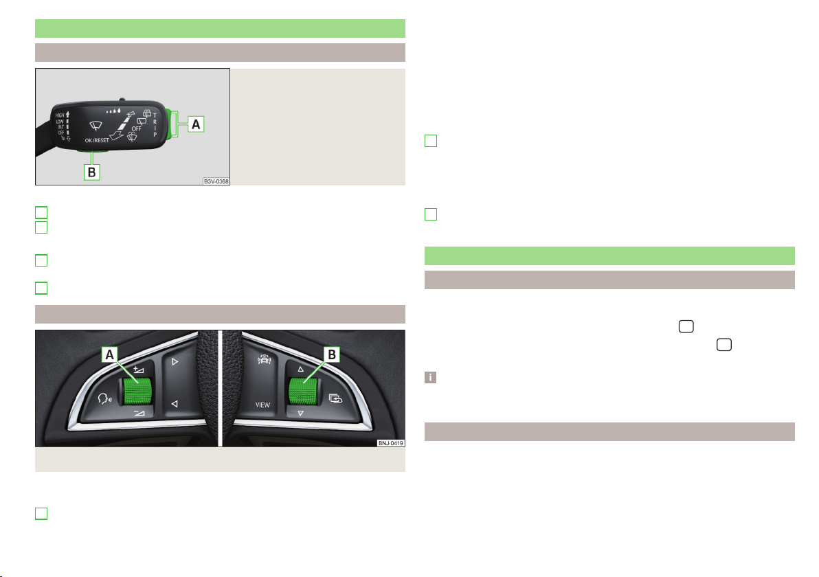
Operation of the information system
Operation using the control lever
Fig. 44
Buttons on the operating lever
Operating the multifunction display
A
Press (up or down) - select data / set values
B
Press - display / confirm indication
Operation of the display menus
A
Press (up or down) - move to the selected menu
Hold (up or down) - display main menu
B
Press - confirm selected menu item
Operation using the multifunctional steering wheel
Skip to next track/station
Switch to previous track/station
Display the assistance systems menu
Depending on equipment:
▶
Operating a digital instrument cluster » page 38
▶
Show previous menu (if one has been selected) / display Telephone
menu
Operating the multifunction display
B
Turn - select data / set values
Press - display / confirm indication
Operation of the display menus
Hold - display main menu
Press - return to a previous level in the menu
B
Turn - move in the selected menu
Press - confirm selected menu item
Driving data (Multifunction display)
Introduction
The driving data display is only possible with the ignition switched on.
The units can be adjusted in Infotainment in the menu
The journey data can be set/reset in Infotainment in the menu
Instrument cluster
.
Note
The setting of the information display is stored in the active user account personalisation » page 55.
/ → →
Units
/ → →
.
Fig. 45 Buttons/dials: on the multifunction steering wheel
Buttons/dials on the multifunction steering wheel
Switch on/off voice control
A
Turn - sets the volume
Press - sound on / off
Information Overview
Overview of driving data (depending on the vehicle equipment).
Range - drive distance in km which can be covered with the existing tank ca-
pacity and with the same driving style. If you drive more efficiently this value
can increase.
Information system
51
Page 54

AdBlue® range - drive distance in km which can be covered with the existing
AdBlue®tank capacity and with the same driving style. If you drive more efficiently this value can increase. When the system detects that AdBlue® can be
refilled, an indication of the minimum and maximum AdBlue ® refilling quantity
appears.
Average fuel consumption - is calculated continuously since the last time the
memory was deleted. After erasing the memory, no data will appear for the
first 100 m driven.
Current fuel consumption - when the vehicle is stationary or slowly moving,
the fuel consumption is displayed in l/h (--,- km/l appears on models for some
countries).
Oil temperature - if the temperature is lower than 50 °C or if there is a fault in
the system for checking the oil temperature, the
Warning when the preset speed is exceeded - allows the setting of a speed
limit where, if exceeded, an acoustic warning signal and a warning message appears on the display of the instrument cluster.
Dynamic Road Sign Display - traffic signs display » page 250, Traffic sign rec-
ognition.
Current speed - digital speedometer.
Average speed - is calculated continuously since the last time the memory
was deleted. After erasing the memory, no data will appear for the first 300 m
driven.
Driving route - distance driven since the last time the memory was deleted.
Driving time - driving time since the last time the memory was deleted.
Conv. consumers - information about the total consumption of the comfort
consumers in l/h and a list of three consumers (e.g. air conditioning etc.), which
have the largest share of fuel consumption.
symbols are displayed.
Infotainment display
Fig. 46
Journey data
In Infotainment in the menu
›
data
.
Screen display » Fig. 46
A
Distance travelled
B
Driving time
C
Average speed
D
Average fuel consumption
E
Transit point rating (
F
Graphic fuel level display (if the estimated range is less than 300 km, the
vehicle starts to approach the symbol )
G
Approximate range
Use the function surfaces to select one of the following presets.
▶
Since start - Driving data for the individual trip
▶
Long-term - Long-term driving data
▶
Since refuel - Data since refuelling
/ tap on function surface → Tap
DriveGreen
Function)
Journey
Warning when exceeding the set speed
The system offers the possibility to set a speed limit beyond which an acoustic
warning signal will sound and the following warning message appears in the
display of the instrument cluster.
Adjust the speed limit while the vehicle is stationary
Select the menu item
›
Set the desired speed limit is 5 km/h steps.
›
Confirm the set value, or wait several seconds; your settings will be saved
›
automatically.
Warning at
and confirm.
52
Using the system
Page 55

Adjusting the speed limit while the vehicle is moving
Select the menu item
›
Drive at the desired speed.
›
Confirm the current speed as the speed limit.
›
The set speed limit can be manually adjusted later if needed.
Reset the speed limit
Select the menu item
›
By confirming the stored value, the speed limit is reset.
›
The speed limit set mode is stored even after the ignition is switched off and
on. After a gap between driving exceeding 2 hours, the pre-set speed limit is
deactivated.
Warning at
Warning at
and confirm.
and confirm.
Memory
Fig. 47
Memory display
The indicator is automatically set back to zero if one of the indicated values is
exceeded.
Since refuel
The driving data is stored in the memory since the last fuel refuelling.
The memory is erased automatically the next time you fill up.
For the Storage choice, repeatedly confirm the selected indication and se-
›
lect the desired memory.
For Deleting the memory for the selected information, hold down the but-
›
ton confirming the specification.
The following driving data are stored.
▶
Average fuel consumption
▶
Distance travelled
▶
Average speed
▶
Driving time
Note
Disconnecting the vehicle battery will delete all memory data.
Menus in the display of the instrument cluster
Introduction
The system saves the data in the three memories described below which are
displayed at the position
Since start
In the memory, driving data is saved for the time between switching on and
switching off the ignition. New data will also flow into the calculation of the
current driving information if the trip is continued within 2 hours after switching off the ignition.
If the trip is interrupted for more than 2 hours, the memory is automatically
erased.
Long-term
The memory gathers driving data from any number of individual journeys up to
a total of 99 hours and 59 minutes driving time or 9999 kilometres driven.
A
» Fig. 47.
The instrument cluster display is a user interface which, depending on the
equipment configuration, provides information about the Infotainment, the
multifunction display, the assistance systems etc.
The menus with details can be operated and displayed using the buttons on
the operating lever or the multifunction steering wheel » page 51.
Main menu items (depending on vehicle equipment)
■
Driving data
■
Assist systems
■
Navigation
■
Audio
■
Telephone
■
Vehicle
» page 51
» page 54
» page 54
» page 54
» page 54;
» page 49
Information system
53
Page 56

Note
■
If warning messages are displayed, these messages must first be confirmed
to access the main menu.
■
The display language can also be set in Infotainment » page 137, Setting the
Infotainment language and» page 144, Setting the Infotainment language.
Navigation
The following information is displayed in the
▶
Driving recommendations
▶
Compass
▶
Last destinations
audio
E.g. the following information is displayed in the
menu item
menu item
Navigation
Audio
menu item.
menu item.
Radio
▶
Currently playing station (name/frequency).
▶
The selected frequency range (e.g. FM) optionally with the number of the
station button (e.g. FM3), if the station is stored in the memory list.
▶
List of available stations (if more than 5 stations can be received).
▶
TP traffic announcements.
Media
▶
Name of the track being played, if necessary, further information regarding
title (e.g. artist, album name), if this information is stored as a so called ID3
tag on the audio source.
Telephone
The call list with the following symbols is displayed in the
menu item
Incoming call
Outgoing call
Missed call
Telephone
menu item.
Symbols in the display
Telephone battery charge (this function is only supported by some mobile
phones)
Signal strength (this function is only supported by some mobile phones)
A telephone connected to the Infotainment system
Missed calls (if there are several missed calls, the number of calls is shown
next to the symbol)
Switch-off microphone
Apple CarPlay
An external device connected to the Infotainment system via Apple CarPlay
can be operated via the multifunction steering wheel as well as via menus in
the instrument cluster display.
The following symbols are displayed in the
Answer the incoming call
Reject incoming call / end call
Activate / deactivate microphone (applies for the infotainment Swing)
Assist systems
menu item
The following systems are activated/deactivated in the
Telephone
menu option.
Assist systems
menu
item.
▶
Lane Assist
▶
Front Assist
▶
Assist system for blind spot monitoring
▶
Rear Traffic Alert
Service intervals
Introduction
Compliance with the service intervals is of crucial importance for the service life and value retention of the vehicle. Never exceed the service date.
The specialist garage will inform you about the type of service interval, the option to change it, and the service scope.
The service interval display in the display of the instrument cluster will notify
you when a service is due.
Proof of service
A specialist garage will confirm the corresponding service record in the service
information system called Digital Service Plan.
We recommend that you always print out the respective service record.
54
Using the system
Page 57

Note
The customer is responsible for covering the cost of all services including
changing or replenishing the oil, even during the warranty period, unless stated
otherwise in the ŠKODA AUTO warranty terms or other binding agreements.
Displaying the distance and days until the next service interval
Fig. 48
Button in the instrument cluster
The details regarding the remaining kilometres or days until the next scheduled
service can be displayed in Infotainment in the menu
with the button in the instrument cluster.
Use the key to display
Switch on the ignition.
›
Press and hold the button A » Fig. 48 until the
›
the display.
Release the button A.
›
In the display, the symbol appears for 4 seconds along with the following
message for the kilometres or days to the next service appointment.
/ → →
Service
menu item is shown in
Events
or
Service messages
Before the next service date has been reached, the symbol as well as a
message about the mileage or days until the next service event appears in the
display after the ignition is switched on.
Once the service interval is reached, the symbol appears in the display after
the ignition is switched on, together with the message:
Resetting the service interval display
Have the display reset by a specialist garage.
We recommend that you do not reset the service interval display yourself. Incorrectly setting the service interval display can cause problems to the vehicle.
Variable service interval
For vehicles with variable service intervals, after resetting the oil change service display in a specialist garage, the values of the new service interval are displayed, which are based on the previous operating conditions of the vehicle.
These values are then continuously matched according to the actual operating
conditions of the vehicle.
Personalization
Introduction
Thanks to the personalisation, more drivers have the opportunity to use a vehicle with individually set system functions by means of a user account which is
assigned to the respective vehicle key.
WARNING
Make all adjustments when the vehicle is stationary - otherwise there is the
risk of accident!
Information system
55
Page 58

Operating principle
Fig. 49
Switching to a different user account
Read and observe on page 55 first.
After unlocking the vehicle and opening the driver's door, all the personalised
functions are adjusted according to the user account that is assigned to the
key which was used to unlock the vehicle.
Any change to the set personalised functions is automatically stored in the active user account.
As part of the personalisation, three default user accounts as well as a
Guest
account are provided.
Switch to a different user account
You can switch to a different user account in the instrument cluster display
» Fig. 49 within 10 seconds after turning on the ignition.
An account can be changed at a later time in Infotainment in the menu
→ →
Vehicle status
all, then use the arrow or switch to
→ (if the
Tyre Pressure Monitoring System
Vehicle status
is displayed first of
).
If an account is selected in which not all of the points required by the system
are set, a configuration wizard can be automatically displayed on the Infotainment screen » page 132.
Electrically adjustable driver's seat (referred to only as seat in the
following)
The seated position adjustment is carried out in the following cases.
▶
After unlocking the vehicle and opening the driver's door (in this case: before
the vehicle was locked, an account with a certain seat setting was selected.
After vehicle unlocking, an account is activated to which a different seat setting is assigned).
▶
After switching to a different user account and at a speed less than 5 km/h.
/
The seat adjustment can be terminated as follows.
▶
By tapping on the function surface
▶
By pressing any key on the seat » page 85.
Cancel
on the Infotainment screen.
Note
Vehicles with the personalisation function are provided with three vehicle
keys.
Overview of some personalized functions
Read and observe on page 55 first.
▶
Setting the electrically adjustable driver's seat.
▶
Exterior mirror adjustment.
▶
Driving mode - setting the
▶
Assistance systems - Lane Assist, parking aid (Park Pilot).
▶
Light - ambient lighting, convenience turn signal, COMING HOME / LEAVING
individual
mode
HOME.
▶
Climatronic - temperature in each individual area, fan speed, recirculation
mode.
▶
Infotainment settings - brightness level of the screen, keyboard arrangement.
▶
Radio - sound settings, station sorting.
▶
Media - shuffle / repeat title, selected video format.
▶
Voice control - acoustic signals.
▶
Navigation - home address, alternative routes, recommended route, reminder
of the lack of fuel.
Note
The scope of the personalisation functions is dependent on the type of Infotainment package.
Setting the personalization
Read and observe on page 55 first.
In Infotainment in the menu
›
tion
.
The following menu items are displayed.
/ tap on function surface →
Personalisa-
56
Using the system
Page 59

Personalisation
Active
- activate/deactivate the personalisation
Select a user account
A list of user accounts with the option to manage user accounts and to switch
to another account.
■
- Account management with the following options:
■
Rename user account
- rename the user account (not applicable to the
Guest
account)
■
Copy settings to another account
- copy the settings of an active user account
to another user account
■
Reset user account
- reset the selected user account to factory settings
Adjusting
■
Key assignment:
■
Manual
- options for assigning the vehicle key to the user account:
- detected vehicle key must be assigned to the active user account
manually
■
Automatic
- detected vehicle key automatically assigned to a different ac-
count of the active user account
■
Assign vehicle key to current user account
- manual assignment of the detected vehicle key to the active user account - follow the instructions on the Infotainment screen
■
Reset all
- reset the personalisation and the user accounts to factory settings
Unlocking and opening
Unlocking and locking
Introduction
The vehicle is equipped with a central locking system which makes it possible
to unlock / lock all the doors, the fuel filler flap and boot lid simultaneously.
The door unlocking can be adjusted individually » page 60.
The unlocking of the vehicle is displayed by the turn signal lights flashing
twice.
If you unlock the vehicle and do not open a door or the boot lid within the next
45 seconds, the vehicle will lock again automatically.
The locking of the vehicle is displayed by the turn signal lights flashing once.
If the driver's door has been opened, the vehicle cannot be locked.
If the doors or the boot lid remain open after the vehicle has been locked, the
turn signal lights do not flash until they have been closed.
WARNING
■
Never leave the key in the vehicle when you exit the vehicle. Unauthorized
persons (e.g. children) could lock the car, turn on the ignition or start the
engine - there is a danger of injury and accidents!
■
When leaving the vehicle, never leave people who are not completely independent, such as children, unattended in the vehicle. These individuals
might not be able to leave the vehicle on their own or to help themselves.
Can be fatal at very high or very low temperatures!
CAUTION
■
Each key contains electronic components; therefore it must be protected
against moisture and severe shocks.
■
Keep the keyway clean. Impurities (textile fibres, dust etc.) have a negative
effect on the functionality of the locking cylinder and ignition lock.
Unlocking and opening
57
Page 60

Unlocking/locking with the remote control key
Fig. 50 Key with fold/out key bit/KESSY key
Read and observe and on page 57 first.
Description of the key » Fig. 50
Unlock button
Lock button
Depending on equipment fitted:
▶
Unlock/unlatch the boot lid (vehicles fitted with manual folding operation)
▶
Open/close/ the boot lid Stop movement of the boot lid (vehicles with
electric folding operation)
A
Locking button for folding the key bit in/out
B
Warning light for the battery charge - if the warning light does not flash
when a button on the key is pressed, the battery is discharged.
Unlock/unlatch the boot lid (vehicles fitted with manual folding operation)
By pressing the button , the lid is unlocked.
By holding the button , the lid is unlocked and unlatched (partially open).
If the lid is unlocked or unlatched using the button, then the lid is automatically locked after closing. The period after which the lid is locked can be set
» page 63.
CAUTION
■
The remote control may be affected by signal superposition of transmitters
that are in the vicinity of the vehicle.
■
The range of the remote control key is about 30 m. The battery must be replaced if the central locking only reacts to the remote control at a distance of
less than approximately 3 m away » page 291.
Remove KESSY emergency key
KESSY key
Fig. 51
Read and observe and on page 57 first.
The emergency key is, for example, intended for the operation of the child
safety, and for switching off/on the front passenger airbag.
Remove retainer tabsA in the direction of arrow 1 » Fig. 51.
›
Remove the emergency key B in the direction of the arrow 2.
›
58
Using the system
Page 61
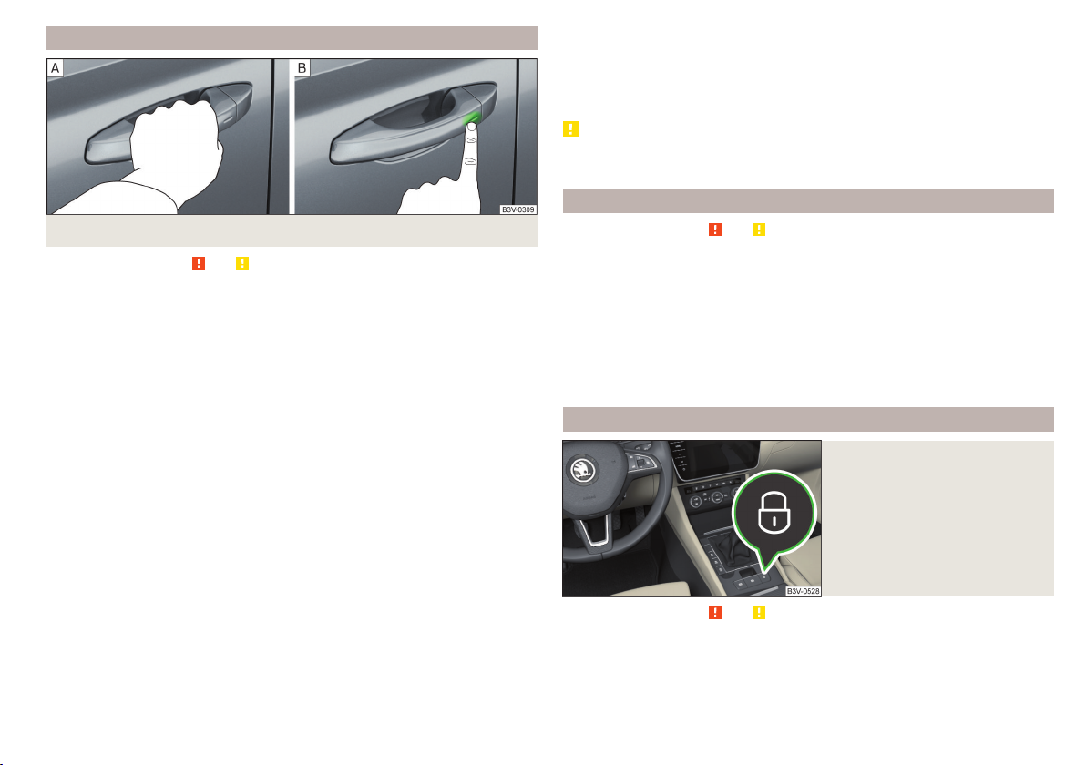
Locking / unlocking - KESSY
Fig. 52 Vehicle unlocking / vehicle locking
Read and observe and on page 57 first.
The KESSY system (Keyless Entry Start Exit System) enables unlocking and
locking of the vehicle without actively using the remote control key.
Grip the door handle to unlock the vehicle » Fig. 52 - .
›
Touch the sensor on the door handle with your finger to lock » Fig. 52 -
›
the vehicle.
When unlocking/locking the vehicle, the key must be at a maximum distance
of approximately 1.5 m from the front door handle.
Information on locking
On vehicles fitted with automatic gearbox, the selector lever must be moved
into the position P before unlocking.
After locking the vehicle, it is not possible to unlock within the next 2 seconds
by touching the door handle. This can be used to check whether the vehicle is
locked.
Protection against inadvertently locking the key in the vehicle
If one of the doors is closed after the vehicle has been locked and the key with
which the vehicle was locked remains in the passenger compartment, the vehicle will be automatically unlocked. After automatically unlocking, the turn signal lights will flash four times. If no door is opened within 45 seconds, the vehicle is automatically locked again.
If the boot lid is closed after locking the vehicle and the key with which the
vehicle was locked remains in the luggage compartment, the lid is automatically unlatched (partially opened). After automatically unlocking, the turn signal
lights will flash four times. The boot lid remains unlatched (partially opened);
the other doors remain locked.
CAUTION
Some types of gloves can affect the unlocking or locking device via the sensors in the door handle.
Deactivating KESSY
Read and observe and on page 57 first.
Lock the vehicle with the button on the key.
›
Within 5 s, touch the sensor on the door handle with your finger » Fig. 52 on
›
page 59 - . Deactivation is confirmed by a single flash of the direction indi-
cators.
To check the deactivation, wait at least 10 seconds and then pull the door
›
handle. The door must remain locked.
The KESSY system is activated again automatically after the vehicle is unlocked.
Locking/unlocking the vehicle with the central locking button
Fig. 53
Central locking button
Read and observe and on page 57 first.
Conditions for the locking/unlocking using the central locking button.
The vehicle is not locked from the outside.
All doors are closed.
Unlocking and opening
59
Page 62

Tolock, press the button Press » Fig. 53
›
Locking is displayed in the button by the illumination of the symbol.
The following applies after locking.
▶
Opening the doors and the boot lid from the outside is not possible.
▶
The doors can be unlocked and opened from the inside by a single pull on the
opening lever of the respective door.
WARNING
Doors locked from the inside make it difficult for rescuers to get into the
vehicle in an emergency – risk to life!
SafeLock
Read and observe and on page 57 first.
SafeLock prevents the doors from behind opened from inside as well as window operation. This makes it more difficult for anyone to break into the vehicle.
Switching on
SafeLock switches on when the vehicle is locked.
This function is enabled after switching off the ignition with the message
safe lock.! Log book!
Switch-on display
With the activated SafeLock, the warning light in the driver´s door flashes for
2 seconds in rapid succession, this then starts to flash at longer intervals.
Switching off
▶
By locking twice within 2 seconds.
▶
or: by deactivating the interior monitor and the towing protection
» page 62.
The warning light in the driver´s door flashes fast for about 2 seconds, goes
out and starts to flash at longer intervals after about 30 seconds.
If the vehicle is locked and the safe securing system is switched off, the door
can be opened separately from the inside by a single pull on opening lever.
The safelock switches on the next time the vehicle is locked.
In the instrument cluster display.
Check
WARNING
If the car is locked and the safe securing system activated, no people must
remain in the car as it will then not be possible to either unlock a door or
open a window from the inside. The locked doors make it more difficult for
rescuers to get into the vehicle in an emergency – risk to life!
Individual settings
Read and observe and on page 57 first.
The following central locking functions can be set individually in Infotainment
in the menu
All doors
The function allows you to unlock all doors, the boot lid and the fuel filler flap.
Single door
The function allows you to unlock only the driver's door and the fuel filler flap
with the radio remote control. KESSY allows the unlocking of a single door
which is in the vicinity of the key, as well as the fuel filler flap. The other doors
and the boot lid are only unlocked once the door handle is unlocked or
touched.
Doors on a vehicle side
This function enables you to unlock both doors on the driver's side and the fuel
filler flap with the radio remote control unit. KESSY allows the unlocking of
both doors which are in the vicinity of the key, as well as the fuel filler flap. The
other doors and the boot lid are only unlocked once the door handle is unlocked or touched.
Automatic locking/unlocking
This function enables the locking of all doors and the boot lid from a speed of
15 km/h. Opening the doors and the boot lid from the outside is not possible.
The renewed unlocking of the doors and the boot lid is carried out when the
ignition key is removed or when the door is opened from inside (depending on
the individual setting for the central locking system).
Note
The individual adjustment of the central locking system is stored (depending
on the Infotainment type) in the active user account personalisation » page 55.
/ → →
Opening and closing
.
60
Using the system
Page 63

Open / close door
Child safety lock
Fig. 54 Door handle/door opening lever
Read and observe and on page 57 first.
To open from outside, unlock the vehicle and pull the door handle A in the
›
direction of arrow » Fig. 54.
To open from inside, pull on the door opening lever B and push the door
›
away from you.
To close from inside, grip the handle C and close the door.
›
WARNING
■
The door must be closed properly, otherwise it could open whilst driving -
risk of death!
■
Only open and close the door when no one is located in the opening/clos-
ing range – risk of injury!
■
Never drive with the doors open - it can be fatal!
■
An opened door can close automatically if there is a strong wind or the
vehicle is on an incline – risk of injury!
Note
On vehicles with door warning lights, these illuminate after the door is opened.
Fig. 55 Rear door: Child safety system switch on / off
Fig. 56
Child safety lock with electric
operation
Read and observe and on page 57 first.
The child safety lock can be operated manually or electrically depending on
equipment.
The child safety lock prevents the rear door from being opened from the inside. The door can only be opened from the outside.
Manually controlled parental settings
To switch on, turn the parental control with the vehicle key in position
›
» Fig. 55.
To switch off, turn the parental control with the vehicle key in position .
›
Child safety lock with electric operation
To switch on/off the child safety lock in the left rear door, press the button
›
A
in the driver's door » Fig. 56.
To switch on/off the child safety lock in the right rear door, press button
›
in the driver's door.
Unlocking and opening
B
61
Page 64

Locking is displayed in the button by the illumination of the symbol .
When with electric operation in addition to the electric window is blocked in
the respective door.
Malfunctions
Read and observe and on page 57 first.
Synchronising the remote control
If the buttons on the remote control key have been operated several times beyond the effective range of the system or the battery in the remote control
key has been replaced and the vehicle cannot be unlocked using the remote
control, the key must be synchronised.
Press any button on the remote control key.
›
Unlock the door with the key in the lock cylinder within 1 minute of pressing
›
the button.
Fault with the central locking
If the warning light in the driver's door initially flashes quickly for around 2 seconds, and then illuminates for 30 seconds without interruption before flashing
again slowly, you will need to seek the assistance of a specialist garage.
A fault in the central locking system means the vehicle doors and the boot lid
cannot be emergency locked or emergency unlocked» page 293.
Failure of the system KESSY
If there is a fault in the KESSY system, the appropriate error message is displayed in the instrument cluster.
Low voltage of the key battery
If the voltage of the key battery is too low, a message appears in the display of
the instrument cluster referring to the need to replace the battery. Replace the
battery » page 291.
Anti-theft alarm system
Introduction
The alarm system triggers audible and visual signals if an attempt is made to
break into the vehicle (hereafter referred to as alarm).
The alarm system is activated automatically approximately 30 seconds after
the vehicle is locked. This is automatically disabled after release.
CAUTION
Before leaving the vehicle, it must be checked that all of the windows, doors
and the sliding/tilting roof are locked in order to ensure the full functionality of
the anti-theft alarm system.
Note
The alarm system has its own power source, service life of which is 5 years. In
order to ensure functionality of the alarm system, we recommend that you get
the alarm checked after this time by a specialist garage.
Alarm trigger
Read and observe on page 62 first.
The alarm is triggered when one of the following unauthorised actions is acti-
vated on the vehicle with an activated warning system.
▶
Opening the bonnet.
▶
Opening the boot lid.
▶
Opening the doors.
▶
Manipulation of the ignition lock.
▶
Towing the vehicle.
▶
Movement in the vehicle.
▶
Sudden and significant voltage drop of the electrical system.
▶
Uncoupling the trailer.
An alarm is triggered also when the driver's door is unlocked and opened by
the lock cylinder.
The alarm is switched off by pressing the button on the key or switching on
the ignition.
Interior monitor and towing protection
Read and observe on page 62 first.
The interior monitor detects movements inside the locked vehicle and then
triggers the alarm.
The anti-towing detects tilts in the locked vehicle and then triggers the alarm.
62
Using the system
Page 65

These functions should be deactivated if there is a possibility that the alarm
will be triggered by movements (e.g. by people or animals) within the vehicle
interior or if the vehicle has to be transported (e.g. by train or ship) or towed.
Disable both functions once
▶
In the infotainment system, in menu
▶
By locking twice within 2 seconds.
Safelock is switched off during deactivation » page 60.
CAUTION
The opened glasses storage compartment reduces the effectiveness of the interior monitor. To ensure the full functionality of the interior monitor, the
glasses storage compartment must always be closed before locking the vehicle.
/ → →
Open and close
,
Manually operated tailgate
Introduction
WARNING
■
Never drive with the boot lid open or ajar, as otherwise exhaust gases
may get into the interior of the vehicle – risk of poisoning!
■
Ensure that the lock is properly engaged after closing the lid. Otherwise,
the lid might open suddenly while the vehicle is moving, even if the lid was
locked – risk of accident!
■
Make sure that when closing the boot lid, no body parts are crushed there is danger of injury!
■
Do not press on the rear window when closing the boot lid, it could crack
– risk of injury!
Open/close boot lid
Fig. 57 Opening / closing tailgate
Read and observe on page 63 first.
To open, press the A button in the direction of arrow 1» Fig. 57.
›
Raise the lid in the direction of the arrow 2.
›
To close, grab the mount B and pull in the direction of arrow 3.
›
Note
Button A » Fig. 57 is deactivated when starting or at a speed of more than 5
km/h. The button is activated again after the vehicle has stopped and a door is
opened.
Setting the delayed locking of the boot lid
Read and observe on page 63 first.
If the boot lid is unlocked with the button on the key, the lid is automatically locked again after closing.
The period after which the boot lid is locked automatically can be extended by
a specialist garage.
CAUTION
There is a risk of unwanted entry into the vehicle before the boot lid is locked
automatically.
Unlocking and opening
63
Page 66

Electric boot lid
Introduction
The boot lid (hereinafter as lid) can be operated electrically and manual in the
event of an emergency » page 65.
WARNING
■
Ensure that the lock is properly engaged after closing the lid. Otherwise,
the lid might open while the vehicle is moving - risk of accident.
■
Never drive with the lid open or unlatched, as otherwise exhaust gases
may get into the interior of the vehicle – risk of poisoning!
■
Only open and close the lid when no one is located in the opening/closing
range – risk of injury!
■
Make sure that no limbs are caught or crushed when closing the lid - risk
of injury!
CAUTION
■
Do not attempt to close the lid manually during electrical motion - there is a
risk of damaging the electric lid operation.
■
Lock the vehicle before driving through a car wash (or with the central locking button). In some car washes the boot lid might open automatically due to
the pressure action of the washing brushes - there is a risk of damage to the
vehicle interior, as well as to the objects being transported.
CAUTION
■
Before opening / closing the flap, check that there are no objects in the
opening / closing area that could damage the flap, and if there are any objects
in the immediate vicinity of the vehicle that could damage the vehicle interior
and the objects being transported.
■
In certain circumstances, if the lid is loaded (e.g. by a thick layer of snow), the
opening process of the lid can be interrupted. Remove the snow from the lid to
re-enable the electrical operation.
■
If the lid closes automatically (e.g. under load of snow), you will hear an intermittent beep.
■
The flap is always to be close before disconnecting the battery.
Description of operation
Lid operation
Fig. 58
Read and observe and on page 64 first.
Ways to open the lid
▶
By pressing the handle A » Fig. 58.
▶
By holding the button C.
▶
By holding the button
If the lid hits an obstacle when closing, it stops and an audible signal sounds.
Ways to close the lid
▶
By pressing the button B » Fig. 58.
▶
By holding the button
less unlocking system). The key must be located at a maximum distance of 2
m from the lid.
▶
By pressing the handle A.
▶
By briefly pressing the lid downwards.
If the flap meets an obstacle when it is closed, it stops, an acoustic signal
sounds and the flap moves back a few centimetres.
D
on the key.
D
on the key (applies to vehicles with the KESSY key-
64
Using the system
Page 67
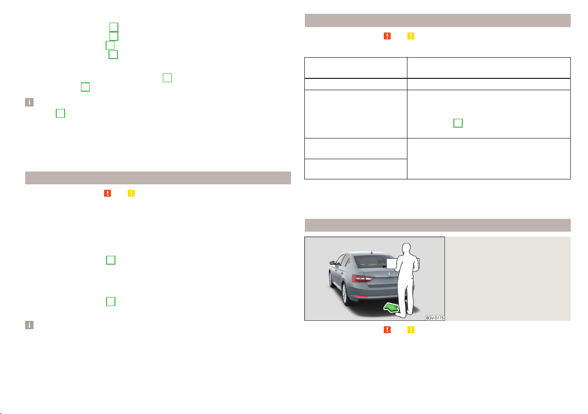
Ways to stop the lid movement
▶
By pressing the button B » Fig. 58.
▶
By pressing the button C.
▶
By holding the button D on the key.
▶
By pressing the handle A.
Audible signals
When opening the door using the buttonC and opening / closing of the flap
using the buttonD audible signals are emitted.
Note
■
Button A » Fig. 58 is deactivated when starting or at a speed of more than 5
km/h. The button is activated again after the vehicle has stopped and a door is
opened.
■
If you rapidly enter the vehicle during the opening or closing process of the
lid, the whole vehicle may jerk and, as a result, the movement of the lid can be
interrupted.
Set the top position of the lid
Read and observe and on page 64 first.
The top position of the lid can be adjusted (e.g. in a limited space to open the
lid due to the garage height or for a more comfortable operation, depending
on the height of the person).
Adjusting the top position of the lid
Stop the lid in the desired position.
›
Press and hold button B » Fig. 58 on page 64 until you hear an acoustic sig-
›
nal.
Adjusting the top starting position of the lid
Carefully raise the flap manually to the limit.
›
Press and hold button B » Fig. 58 on page 64 until you hear an acoustic sig-
›
nal.
Note
The top position which is reached when the lid opens automatically, is always
lower than the maximum top position which can be reached when the lid is
opened manually.
Malfunctions
Read and observe and on page 64 first.
Examples of operational malfunctions
Description of the malfunction
The lid cannot be opened Unlocking the lid » page 294
The lid does not react to an
opening signal
The lid remains in the top
position
The lid is open and the battery was disconnected
Close manually
Close the door slowly, push down the lid, push in the lock on the centre of the
edge, above the ŠKODA logo.
Remedy
Removing a possible obstacle (e.g. snow), reopening the lid » page 64
Press handle A » Fig. 58 on page 64 and pull
the lid upwards
Manual closing of the lid
Operating contactless boot lid
Fig. 59
Opening the boot lid
Read and observe and on page 64 first.
Depending on equipment the boot lid can be operated without contact.
The ignition must be switched off and you have to have the vehicle key on
your person.
Unlocking and opening
65
Page 68

To open/close, move one foot in the sensor area below the rear bumper
›
quickly in the direction of the arrow » Fig. 59.
The flap opens / closes automatically. When opening the fully closed flap, the
brake light in the rear window lights up. An acoustic signal is sounded when
closing the lid.
If the lid does not move, then repeat the operating process after a few seconds.
The lid movement can be stopped by a rapid swinging of the foot. Swinging
the foot again will continue the lid movement.
The function can be deactivated/activated in Infotainment in the menu
→ →
Opening and closing
→
“Easy Open”
.
/
We recommend that the function is deactivated in the following cases:
▶
Installation of a roof rack.
▶
Connecting a trailer (accessory) to the towbar.
▶
Manual vehicle wash.
▶
Maintenance and repair work in the back of the vehicle.
When connecting a device to the trailer socket the deactivation of the function takes place.
Note
With heavy rain or a dirty rear bumper, under certain circumstances that there
may be limitations, or the automatic deactivation of the contactless opening
function of the boot lid may occur.
Window operation
Introduction
WARNING
■
Always close the window carefully and controlled. Doing so may may
cause yourself or fellow passengers considerable crushing injuries.
■
The system is fitted with a force limiter » page 67. If there is an obstacle
(e.g. In the event of a body part becoming trapped) the closing process is
stopped and the window goes down by several centimetres. However, the
windows should be closed carefully – risk of injury.
CAUTION
■
Keep the windows clean to ensure the correct functionality of the electric
power windows.
■
Always close the windows before disconnecting the battery.
Note
If the windows are opened, dust and other dirt can get into the vehicle and the
wind noise is more at certain speeds.
Open / close Window
Buttons for window lifter
Fig. 60
Fig. 61
Button of the window lifter on
the passenger side
Read and observe and on page 66 first.
All windows can be operated from the driver's seat. The window in the front
passenger door and the windows in the rear doors are operated via the button
in each door.
66
Using the system
Page 69
Power window buttons » Fig. 60
A
Front door left
B
Front door right
C
Rear door, left
D
Rear door, right
E
Deactivate/activate the buttons in the rear doors (the deactivation may be
advantageous if, for example, children are transported on the rear seats)
F
Deactivation / activation of the key in the rear door left (part of the child
safety lock with electric operation)
G
Deactivation / activation of the key in the back door right (part of the child
safety lock with electric operation)
Open/close window
To open, lightly press the appropriate button down and hold it until the win-
›
dow has moved into the desired position.
or: Press the button to the stop; the window automatically opens fully. Re-
›
newed pressing of the button causes the window to stop.
To close, pull gently on the top edge of the corresponding button and hold
›
until the window has moved into the desired position.
or: Pull the button briefly to the stop, the window automatically closes fully.
›
Renewed pulling of the button causes the window to stop immediately.
Disable / enable buttons in the rear doors
To deactivate/activate the buttons in the rear doors, press the E button. If
›
the buttons in the rear doors are deactivated, the warning light illuminates
E
in the
or: On vehicles with child safety lock with electric operation, press the re-
›
spective key F or G. If the buttons in the rear doors are deactivated, the
warning light illuminates in the respective button F or G.
■
After switching off the ignition, the windows can still open and close for
about 10 minutes.
■
After the driver or front passenger door is opened, the operation of the window is only possible with the button A» Fig. 60, in which case this is pressed
or pulled for approx. 2 seconds.
button.
Note
Force limiter
Read and observe and on page 66 first.
The electrical power windows are fitted with a force limiter.
If there is an obstacle, the closing process is stopped and the window goes
down by several centimetres.
If the obstacle prevents the window from being closed during the next 10 sec-
onds, the closing process is interrupted once again and the window goes down
by several centimetres.
If you attempt to close the window again within 10 seconds of the window being moved down for the second time, even though the obstacle was not yet
been removed, the closing process is only stopped. During this time it is not
possible to automatically close the window. The force limiter is still switched
on.
The force limiter is only not operational if you attempt to close the window
again within the next 10 seconds – the window will now close with full force!
If you wait longer than 10 seconds, the force limiter is switched on again.
Window convenience operation
Read and observe and on page 66 first.
The convenience operation for the window offers the option to open/close all
the windows at once (or only the window in the driver's door). The convenience operation function can be adjusted individually in Infotainment in the
menu
Opening
›
›
Closing
›
›
›
/ → →
Press and hold the button on the key.
or: Switch off the ignition, open the driver's door and hold the key A until it
stops in the open position » Fig. 60 on page 66.
Press and hold the button on the key.
or: Switch off the ignition, open the driver's door and hold the key A until it
stops in the closed position » Fig. 60 on page 66.
In the KESSY system, hold your finger on the sensor on the outside of the
door handle of the front door » Fig. 52 on page 59.
Opening and closing
.
Unlocking and opening
67
Page 70

The convenience operation will only function correctly if all the windows automatically open/close properly.
Convenience opening or closing the window using the key in the driver's door
locking cylinder is only possible within 45 seconds of locking the vehicle.
The movement of the window is stopped immediately when the respective
button is released.
Note
The settings for the window convenience operation are stored (depending on
the Infotainment type) in the active user account personalisation » page 55.
Malfunctions
Read and observe and on page 66 first.
Repeatedly opening and closing the window can cause the window mechanism
to overheat and become temporarily blocked. You will be able to operate the
window again as soon as the operating mechanisms has cooled down.
After disconnecting the vehicle battery, automatic opening / closing the window can be deactivated. In this case the system must be activated as follows.
Activate window operation
Switch-on the ignition.
›
Pull the top edge of the button and close the window.
›
Release the button.
›
Pull up the respective button and hold for 1 second.
›
Panoramic tilting / sliding sunroof
Introduction
The panorama sliding/tilting roof (hereinafter referred to as sliding/tilting roof)
can only be operated when the ignition is turned on and when the outdoor
temperature is no lower than -20 °C.
The sliding/tilting roof can still be operated for approx. 10 minutes after
switching the ignition off. After opening the driver or front passenger door, it
is no longer possible to operate the sliding/tilting roof.
WARNING
When operating the sliding/tilting roof and the sunshade, proceed with
caution to avoid causing crushing injuries – risk of injury!
CAUTION
■
During the winter, remove any ice and snow in the vicinity of the sliding/tilt-
ing roof before opening it to prevent any damage to the opening mechanism.
■
Always close the sliding/tilting roof before disconnecting the battery.
Operation
Operation of the sliding/tilting roof
Fig. 62
Read and observe and on page 68 first.
Operation of the sliding/tilting roof » Fig. 62
1
Gradual opening
2
Complete opening
3
Gradually reset
4
Fully reset
5
Gradual opening
6
Fully opening
After the first press, the sliding/tilting roof stops in the position where the
intensity of the wind noise is low (at speeds of approx. less than 80 km/h).
Press again and the sliding/tilting roof goes to the stop.
7
Gradual closing
8
Complete closing
68
Using the system
Page 71

Force limiter
Read and observe and on page 68 first.
The sliding/tilting roof is fitted with a force limiter.
If there is an obstacle, the closing process is stopped and the glass pane re-
tracts by several centimetres.
WARNING
If the sliding/tilting roof is closed by holding down the switch 7 / 8,
» Fig. 62 on page 68and the closing process is hindered by an obstacle, then
when attempting to close for a third time, the force limiter is rendered in-
operable (if the period of 5 s is not reached between the individual at-
tempts to close). The sliding/tilting roof closes with full force - it may cause
injury.
Convenience operation of the sliding / tilting roof
Read and observe and on page 68 first.
The convenience operation makes it possible to open or close the sliding/tilting roof using the key or the KESSY system via the sensor in the door handle
of the front door.
To open out, press and hold the button on the key.
›
To close, press and hold the button (with KESSY, hold your finger on the
›
sensor on the outside of the door handle of the front door).
By interrupting the locking process, the closing operation is interrupted.
Activate operation of the sliding/tilting roof
Fig. 63
Operation of the sliding/tilting
roof
Read and observe and on page 68 first.
If the operation of the sliding/tilting roof is deactivated (e.g. after disconnecting and connecting the battery), then operation will have to be activated.
Switch on the ignition, pull the switch on the recess all the way down in the
›
direction of arrow 1 » Fig. 63 and hold.
The sliding/tilting roof opens/closes again after around 10 seconds.
Release the lever.
›
Manually operated sunshade
Fig. 64
Operation of the sunshade
Read and observe and on page 68 first.
To open, pull the handle in the direction of arrow A » Fig. 64.
›
To close, pull the handle in direction of arrow B.
›
Unlocking and opening
69
Page 72

Electrically operated sunshade
Lights and visibility
Fig. 65
Buttons for operating the sunshade
Read and observe and on page 68 first.
Operation of the sunblind » Fig. 65
Open - by pressing (press again - sunshade stops moving)
Close - by pressing (press again - sunshade stops moving)
The sunshade can also be operated by pressing and holding the appropriate
button (starts movement of the sunshade) and releasing it when the sunshade
reaches the desired position.
Activating operation of the sunshade
Read and observe and on page 68 first.
If the operation of sunshade is deactivated (e.g. after disconnecting and connecting the battery), then the operation will have to be activated.
Switch on the ignition, press and hold the » Fig. 65 on page 70 button.
›
The sunshade opens and closes again after around 10 seconds.
Release the button.
›
Light
Introduction
Unless otherwise stated, the lights only work when the ignition is switched on.
For the basic position of the light switch, use position .
Note
The headlights may mist up temporarily. When the light is switched on, the
light-emitting surface demists after a short period of time.
Operating the lights
Fig. 66
Light switch
To switch on/off the lights, turn the A » Fig. 66 switch to one of the following
positions (equipment-dependent).
Switching off lights (except daytime running lights)
Switching the light on/off automatically » page 72
Switching on the parking lights or parking lights on both sides » page 74
Switching on the low beam
Headlight range control of the Halogen headlights
The headlight range can be set in Infotainment in the menu
The range of the halogen headlights can be set on the screen, in accordance
with the vehicle load, to the following basic settings.
Front seats occupied, boot empty
All seats occupied, boot empty
/ → →
Light
.
70
Using the system
Page 73

All seats occupied, boot loaded
Driver seat occupied, boot loaded
In the event of another vehicle loading condition, the setting for positions . .
can be used.
The Xenon headlights feature no manual headlight range control. After
switching on the ignition, adjust these automatically to the load and driving
condition of the vehicle.
WARNING
Always adjust the headlight range control to comply with the following
conditions and prevent accidents.
■
The vehicle does not dazzle other road users, especially oncoming vehi-
cles.
■
The beam range is sufficient for safe driving.
Note
■
If, with a dipped beam, the ignition is turned off, then the dipped beam will
automatically switch off and the parking lights will come on. Does not apply to
the position , as long as the conditions are met for the COMING HOME
function . The parking lights are switched off when the ignition key is removed
(for vehicles with the KESSY system, after opening the driver's door).
■
If there is a fault in the light switch, the low beam comes on automatically.
Daytime running lights
The daytime running lights illuminate the area in front of and to the rear of the
vehicle (only applicable for some countries).
The lights are switched on automatically if the following conditions are
met.
The light switch is in the position or
The ignition is switched on.
WARNING
Always switch on the low beam when visibility is poor.
Note
The light can operate automatically under certain circumstances, even if the
light switch is in position .
.
Turn signal and main beam
Fig. 67
Operating lever: Turn signal and
main beam operation
Control stalk positions » Fig. 67
Switch on the right turn signal
Switch on the left turn signal
Switch on main beam (spring-tensioned position)
Switch off main beam / headlight flasher on (spring-tensioned position)
The main beam can only be switched on when the low beam lights are on.
The headlight flasher can be used even if the ignition is switched off.
The turn signal switches off automatically depending on the steering angle af-
ter turning.
Use the control stalk to switch on/off the headlight assistant» page 74.
Comfort indicating
When the control talk is pressed slightly up or down, the respective turn signal
indicates three times.
If during the convenience turn signal, the operating lever is pressed in the opposite direction, the indicating will stop.
Convenience signalling can be activated/deactivated in Infotainment in the
menu
/ → →
Light
/
WARNING
Only turn on the main beam or the headlight flasher if other road users will
not be dazzled.
Lights and visibility
71
Page 74

Note
The setting (activation/deactivation) of the convenience turn signal is stored
(depending on the Infotainment type) in the active user account personalisation » page 55.
Automatic driving light control
Fig. 68
Light switch: Position
WARNING
The automatic driving lamp control (position ) only operates as a support and does not release the driver from his responsibility to check the
lights and, if necessary, to switch on the light depending on the prevailing
light conditions.
CAUTION
Poorer visibility is evaluated by a sensor mounted below the windscreen in the
holder of the rear-view mirror. Do not cover the sensor - the system can be
affected.
Note
The setting (activate/deactivate) of the automatic driving light control during
rain is stored (depending on the Infotainment type) in the active user account
personalisation » page 55.
If the light switch is in position
» Fig. 68, then the lights are automatically
switched on/off to suit current light or weather conditions (rain), depending on
the equipment.
If the light switch is in position
, the lettering
illuminates next to the
light switch. If the light is switched on automatically, the symbol also illuminates next to the light switch.
Automatic driving light control in the rain (referred to as function in the
following)
The dipped beam is switched on automatically if the following conditions are
met.
The function is activated.
The light switch is in the position .
The windscreen wipers are on for more than 30 s.
The light turns off automatically about 4 minutes after turning off the wipers.
Setting, activation/deactivation
The following functions can be set or activated/deactivated in Infotainment in
the menu
▶
Sensitivity adjustment of the sensor for determining the lighting conditions
/ → →
Light
.
for automatic driving light control
▶
Automatic driving light control during rain
72
Using the system
Xenon headlight
The Xenon headlights (hereinafter referred to as just system) use the driving
data to automatically ensure the for the best possible light cone in front of the
vehicle.
The system operates automatically in the following modes: urban, extra-urban,
highway, rain, fog, adjusting the lighting direction of the headlights for the
road illumination in curves.
The system works as long as the light switch is in position
WARNING
If there is a system malfunction the headlights are automatically lowered to
the emergency position, which prevents a possible dazzling of oncoming
traffic. This reduces the cone of light in front of the vehicle. Seek help from
a specialist garage.
.
Page 75

Fog lights/rear fog light
Fig. 69
Light switch – switch on front
and rear fog lights
Switching on the fog lights/rear fog lights is possible under the following
conditions.
The lights switch is in position
To switch on the fog lights, turn the light switch to position 1; the warning
›
light illuminates in the instrument cluster.
To switch on the rear fog lights, pull the light switch to position 2; the
›
warning light illuminates in the instrument cluster.
If the vehicle is not equipped with fog lights, the rear fog lights can be switch-
ed on by pulling the light switch to the only possible setting.
Switch off the fog lights/rear fog lights in reverse order.
Note
If an accessory is connected to the trailer socket, the rear fog lamp does not
light up on the vehicle.
,
or » Fig. 69.
function CORNER
The CORNER function automatically switches on the fog lights on the respective side of the vehicle (e.g. when cornering or steering), if the following conditions are fulfilled.
The turn signal is turned on or the front wheels are severely locked (in the
event of conflict between the two versions, has turn signal has the higher
priority).
The vehicle speed is below 40 km/h.
The low beam is switched on.
The fog lights are not switched on.
The two fog lights are switched on when you shift into the reverse gear.
COMING HOME / LEAVING HOME
The function COMING HOME ensures that the vehicle's environment is illuminated after switching off the ignition and opening the driver's door.
The function LEAVING HOME ensures that the vehicle's environment is illuminated after unlocking the vehicle with the radio remote control unit.
The function switches the light on only if there is poorer visibility and the light
switch is in the position .
The two functions can be used in Infotainment in the menu
(activated/deactivated and adjusted).
CAUTION
■
Poorer visibility is evaluated by a sensor mounted below the windscreen in
the holder of the rear-view mirror. Do not cover the sensor - the system can
be affected.
■
If this option is always enabled, then the battery is heavily loaded.
Note
The setting of the two functions is stored (depending on the Infotainment
type) in the active user account personalisation » page 55.
/ → →
Light
Hazard warning light system
Fig. 70
Button for hazard warning light
system
To switch on/off, press the button » Fig. 70.
›
When switching on, all the turn signal lights as well as the warning light in
the button flash simultaneously with the control lights in the instrument
cluster.
Lights and visibility
73
Page 76
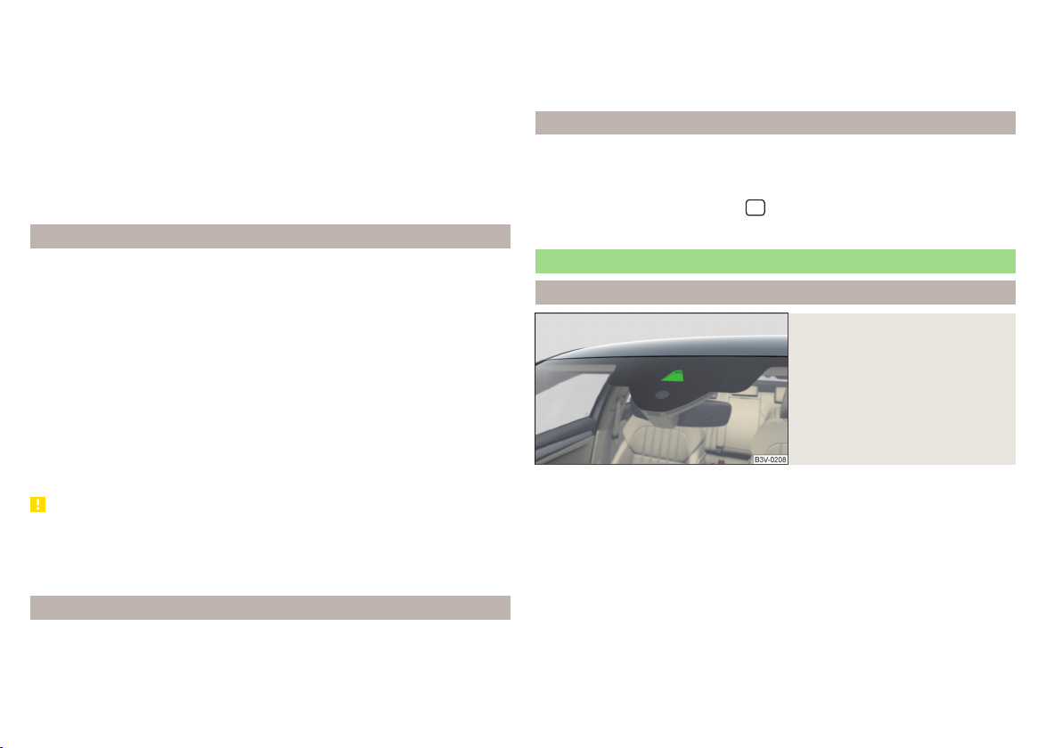
The hazard warning light system can also be operated if the ignition is switched off.
If one of the airbags is deployed, the hazard warning light system will switch
on automatically.
The automatic activation of hazard warning lights can take place during a
heavy braking. After starting or accelerating the hazard warning system is automatically switched off.
When the hazard warning system is on and the turn signal is switched on, the
hazard warning lights are switched off temporarily and only the turn signal
flashes on the relevant side of the vehicle.
Parking light
The side light is provided for lighting of the parked vehicle.
Switching on the side light on one side
Switch off the ignition.
›
Press the control lever all the way into position or until it stops » Fig. 67
›
on page 71.
The parking lights on the respective side of the vehicle are turned on.
Switching on the side light on both sides
Turn the ignition on and turn the light switch to position » page 70.
›
Switch off the ignition and lock the car.
›
After removing the ignition key and opening the driver's door, an audible warning sounds. After a few seconds, or after closing the driver's door, the acoustic
warning signal stops.
CAUTION
■
Turning on the parking light means the battery is heavily loaded.
■
The parking lights may switch off automatically due to a low battery charge.
If the two-sided parking lights are switched on when the ignition is off, the
parking lights will not switch on automatically.
Entry space lighting
The lighting is positioned on the lower edge of the exterior mirror and illuminates the entry area of the front door.
The lighting switches on after unlocking or opening the vehicle door (depending on the lighting conditions).
The lighting switches off after around 30 seconds after closing the front door
or switching on the ignition.
Driving abroad
When driving in countries with opposing traffic system (traffic on the
left/right), headlights may dazzle oncoming traffic.
Therefore, the Xenon headlight setting must be adapted by turning on travel
mode in infotainment in the menu
automatic beam adjustment is made ahead of the vehicle.
/ → →
Light
menu. In this mode, no
Headlight Assist (Light Assist / Dynamic Light Assist)
Introduction
Fig. 71
Sensor window for the headlight assistant
The headlight assistant (referred to as just system in the following) automatically switches the main beam on/off, if necessary, adjusts the beam of the
front headlights in accordance with the existing traffic situation (other vehicles) and environmental conditions (e.g. driving through a lit village).
The switching on/off of the main beam, if necessary, the adaptation of the
headlight, is controlled by a sensor » Fig. 71.
Depending on the equipment, the following system versions can exist.
Light Assist
Dynamic Light Assist
lights in order to prevent dazzling the oncoming and preceding vehicles, while
ensuring the highest possible illumination of the road edges.
automatically switches the main beam on/off.
automatically adjusts the light cone shape of the front head-
74
Using the system
Page 77

If the driving mode Eco » page 244, Select the driving mode (Driving Mode
Selection) or travel mode » page 74, Driving abroad is selected, the automatic
adjustment of the beam is deactivated,
main beam on/off automatically.
If the Xenon headlights are in the mode rain or fog » page 72, then
Assist
is deactivated.
If there is a fault, the error message will appear in the instrument cluster display. Seek help from a specialist garage.
WARNING
The system is used only for support, thus the driver is not released from his
obligation to manually adjust the main or low beam according to the given
ambient conditions (e.g. in unfavourable lighting and weather conditions, as
when passing poorly lit road users, if necessary, when the area in front of
the sensor is covered by an obstacle).
CAUTION
Do not attach any stickers or similar objects in front of the sensor on the windscreen to avoid impairing the function of the system.
Note
The adjustment of the headlight assistant in Infotainment is stored (depending
on the Infotainment type) in the active user account personalisation » page 55.
Dynamic Light Assist
only switches the
Dynamic Light
Operating conditions
Read and observe and on page 75 first.
The system works under the following conditions.
The system is activated in Infotainment in the menu
activated.
The light switch is in the position .
The system is activated » page 75, System on/off.
The vehicle speed is over 60 km/h or for some countries more than 40
km/h.
The windscreen is clean in the sensor area.
/ → →
light
System on/off
Fig. 72
Operating lever: Headlamp assistant
Read and observe and on page 75 first.
Switch on the system
Push the lever into the sprung position A » Fig. 72. The following indicator
›
light lights up in the instrument cluster display.
Switch off the system
If the high beam is switched on automatically, move the lever into the sprung
›
position B. The warning light goes out. The high beam turns off.
If the high beam is is not switched on automatically, move the lever into the
›
sprung position A. The warning light goes out. The high beam turns on.
The high beam switches off automatically when the speed falls below 30 km/h
(but the system remains switched on).
Interior lighting
Introduction
The inner lighting also works if the ignition is switched off. With the ignition
off (or after a door is opened),the lights will automatically switch off after approximately 10 minutes.
Lights and visibility
75
Page 78

Operation of the lights from the front seats
Interior light, rear
Fig. 73
Operation of the lights from the
front seats
Switch on/off (by pressing the relevant switch) » Fig. 73
A
Automatic operation
B
C
D
Automatic operation - switch
Rear lighting
Depending on equipment fitted:
▶
Reading light left
▶
Front and rear lighting
Reading light right
The system is turned on when any of the following is present.
▶
The vehicle is unlocked.
▶
One of the doors is opened.
▶
The ignition key is removed.
The system is turned off when any of the following is present.
▶
The vehicle is locked.
▶
The ignition is switched on.
▶
About 30 seconds after all the doors have been closed.
Fig. 74
Interior lights at the rear: Variant
1
Fig. 75
Interior lights at the rear: Version 2/version 3
The rear lighting (variants 1 and 3) is controlled together with the automatic
operation of the lighting from the front seats.
Variant 1 - switch on/off (by pressing the relevant switch) » Fig. 74
A
Reading light left
B
Reading light right
Variant 2 - operation (by moving the light lens C) » Fig. 75
Switching on
Switching off
Automatic operation (the light is switched on/off automatically together
with the front light)
Variant 3 - switch on/off (by pressing the relevant switch) » Fig. 75
D
Reading light left
Reading light right
76
Using the system
Page 79

Ambient lighting
Fig. 76
Setting the ambient lighting
The ambient lighting illuminates the dashboard and side door trim panels in
colour, and the footwell in white.
The switching on of the lighting takes place automatically after opening the
door, switching off occurs automatically after the locking of the vehicle or 30
seconds after the closing of the door with the ignition switched off.
The ambient lighting can be adjusted in Infotainment in the menu
Background lighting
→
.
Description of the function surfaces » Fig. 76
A
Enable / disable the background lighting
B
Activating of the brightness setting for all areas at the same time
C
Activating of the brightness setting for the dashboard area
D
Activating the brightness controls for the door area
E
Activating the brightness setting for the footwell area
F
Choice of colour options / brightness adjustment
G
Function surfaces for selecting lighting colour / brightness adjustment
To display
B. C. D
and E tap on the function surface .
Vehicles by selecting the driving mode
For vehicles with driving mode selection » page 244 The lighting can be
A
switched on automatically or manually
» Fig. 76. A change in the illumination colour occurs automatically due to the driving mode change or manually
by selecting one of the colour options. In individual mode, the last manually selected colour is displayed.
/ →
Note
The adjustment of the ambient lighting is stored (depending on Infotainment
type) in the active user account personalisation » page 55.
Visibility
Introduction
WARNING
No objects should be attached to the sun visors, which could limit the view
or endanger the vehicle occupants during sudden braking or should the vehicle collide.
Windscreen and rear window heater
Fig. 77 Buttons for the front and rear window heater: Climatronic /
manual air conditioning
Read and observe on page 77 first.
The heating for quick defrosting and ventilation of the front /and rear window.
The heating only works when the engine is running.
Buttons for the heating (depending on vehicle equipment) » Fig. 77
Switching the windscreen heater on/off
Switch on/off the rear window heater
When the heating is switched on, a light illuminates inside or below the button.
The heating automatically switches off after ten minutes.
Lights and visibility
77
Page 80

If the engine is switched off when the heating is on and turned back on again
within 10 minutes, the heating is continued.
Note
■
If the on-board voltage decreases, the heating switches off automatically
» page 274, Automatic consumer shutdown - discharge protection of the vehi-
cle battery.
■
If the lighting inside or below the button flashes, the heater will not work because of the low charge of the battery.
■
If the Climatronic recognises that the windshield could fog up, the windshield
heating is automatically switched on. This function can be activated/deactivated on the Climatronic control panel in the menu
→
Front sun visors
Fold down flap / flip up flap / make-up mirror and parking per-
Fig. 78
mit holder
Read and observe on page 77 first.
Operation and description of the sun visor » Fig. 78
1
Swivel the visor towards the windscreen
2
Swivel cover towards the door
A
Make-up mirror with cover (the cover can be pushed in the direction of
the arrow)
B
Light (turns on when the cover of the make-up mirror is pushed to one
side)
C
Parking ticket holder
Sunshade
Fig. 79 Sun screen
Read and observe on page 77 first.
The sun screen is located in a housing on the luggage compartment cover.
To roll down, pull the sunshade by the handle A in direction of arrow 1 and
›
suspend in the magnetic holder B in the direction of arrow 2 » Fig. 79.
To roll up, pull the sunshade by the handle A out of the holder B against
›
the direction of arrow 2. Hold the sunshade so that this can slowly roll back
in without damaging.
78
Using the system
Page 81

Sunshade in the rear doors
Fig. 80 Sun blind on the rear door
Read and observe on page 77 first.
To roll down, pull out the sunshade by the handle A in direction of arrow
›
and suspend in the holder B on top edge of the door in the direction of arrow 2 » Fig. 80.
To roll up, hold the sunshade by the handle A and remove it from the holder
›
B
against the direction of arrow 2. Hold the sunshade so that this can
slowly roll back in without damaging.
1
Windscreen wipers and washers
Introduction
The windscreen wipers and the wash system operate if the ignition is switched
on and the bonnet and boot are closed.
WARNING
Do not use the windscreen washer system at low temperatures, without
heating the windscreen beforehand. The window washer fluid could otherwise freeze on the windscreen and restrict the view to the front.
CAUTION
■
If the windscreen wipers are in rest position, they cannot be folded out from
the windscreen. The wipers must be set to the service position to raise them
off the windscreen » page 294.
■
In cold temperatures and during the winter, check before switching on the
ignition that the wiper blades are not frozen to the windscreen. If the windscreen wipers are switched on when the blades are frozen to the windscreen,
this may damage both the blades and windscreen wiper motor.
■
Carefully release the frozen-on windscreen wiper blades from the windscreen and remove snow and ice.
■
Handle the windscreen wipers with care - there is the risk of damaging the
windscreen with the windscreen wiper arms.
■
Do not switch on the ignition when the front windscreen wiper arms are folded down - there is the danger of damaging the bonnet by the windscreen
wiper arms.
■
If there is an obstacle on the windscreen, the wipers will try to push away the
obstacle five times. Thereafter, the wipers will stop to prevent them becoming
damaged. Turn on the wipers again only after the obstacle has been removed.
Note
■
Each time the ignition switches off for the third time, the position of the
windscreen wipers changes. This counteracts an early fatigue of the wiper
blades.
■
The windscreen washer nozzles for the windscreen are heated when the engine is running and the outside temperature is less than +10 °C.
Lights and visibility
79
Page 82

Front wipers and washers
Fig. 81
Operating the windscreen wipers and washing system at the
front
Read and observe and on page 79 first.
Fast disk wiping
Slow disk wiping
Depending on equipment fitted:
▶
Intermittent wipe of the windscreen
▶
Automatic windscreen wiping in the rain
Wipers and washers off
Single windscreen wipe (sprung position)
A
Setting of windscreen wiper interval for the position
switch in the direction of the arrow, the windscreen wipers will wipe more
often
Spraying and wiping the windscreen (sprung position)
Spraying and wiping the windscreen
After releasing the operating lever, the wipers will make from 2 to 3 wiper
strokes.
At a speed of more than 2 km/h, the wiper wipes once again 5 seconds after
the last wiper stroke in order to wipe the last drops from the windscreen. This
function can be activated/deactivated by a specialist garage.
Automatic windscreen wiping in the rain can be used in Infotainment in the
menu
/ → →
Mirrors and wipers
(activated/deactivated).
WARNING
Automatic wiping during rain is only a support. The driver is not released
from the responsibility to set the function of the windscreen wipers manually depending on the visibility conditions.
- by setting the
Note
■
If the wiping is carried out without interruption, the wiping speed varies de-
pending on the vehicle speed.
■
The setting (activation/deactivation) of the automatic windscreen wiping in
the rain is stored (depending on the Infotainment type) in the active user account personalisation » page 55.
Rear window wipers and washers
Fig. 82
Operating the windscreen wipers and washing system
Read and observe and on page 79 first.
Spraying and wiping the windscreen (sprung position) - after releasing the
control stalk, the wipers perform another 2 to 3 wiper strokes
Windscreen wiping
Wipers and washers off
Automatic rear wiper
If the windscreen wiping is performed without interruption, then the automatic regular intermittent wiping of the rear window takes place.
This function can be activated/deactivated in Infotainment in the menu
→ →
Mirrors and wipers
(activated/deactivated).
Note
■
The rear window is wiped automatically if the windscreen wipers are on
when reverse gear is selected.
■
The setting (activation/deactivation) of the automatic rear window wiping in
the rain is stored (depending on the Infotainment type) in the active user account personalisation » page 55.
/
80
Using the system
Page 83

Headlight cleaning system
Read and observe and on page 79 first.
Headlights are cleaned under the following conditions.
The low beam is switched on.
The outside temperature is about -12° C to +39° C.
To clean the headlights, the headlamp is also sprayed after spraying the windscreen every first and tenth time. Setting the spray interval can be carried out
by a specialist garage.
To ensure the correct functioning of the system, even in winter, this needs to
be regularly cleared of snow and ice (e.g. using the de-icing spray).
Rear view mirror
Introduction
WARNING
Exterior mirrors increase the field of view, however, make objects appear
smaller and further away. Therefore, use the rear-view mirror to determine
the distances to the following vehicles.
Interior mirror dimming
Rear-view mirrors with automatic dimming: Version 1/version 2
Fig. 84
Fig. 83
Rear-view mirrors with manual
dimming
WARNING
■
The mirrors with automatic dimming contain electrolyte fluid which may
leak if the mirror glass is broken - this can irritate skin, eyes and the respiratory system.
■
If your eyes or skin come into contact with the electrolyte fluid, immediately wash the affected area for a few minutes with plenty of water. Seek
medical assistance if required.
Read and observe on page 81 first.
Mirrors with manual dimming » Fig. 83
1
Basic position of the mirror (not dimmed)
2
Mirror blackout
Mirror with automatic dimming
The mirror dimming » Fig. 84 is automatically controlled after the engine start.
When the interior lights are switched on or the reverse gear is engaged, the
mirror moves back into the basic position (not dimmed).
Lights and visibility
81
Page 84

WARNING
■
Attach external devices (e.g. navigation system) not in the vicinity of the
mirror with automatic dimming. The illuminated display of an external device can affect the function of the rear-view mirror - it could cause an accident.
■
The automatic dimming mirror only functions smoothly if the light falling
on the sensors is not compromised (e.g. by the sunshade at the back). The
sensors are located on the front and back of the mirror.
Exterior mirrors
Fig. 85
Exterior mirror operation
Read and observe on page 81 first.
The exterior mirrors can (depending on vehicle equipment) have a manual or
electric fold-in function, automatic dimming and memory function.
The rotary knob can be moved into the following positions (depending on
vehicle equipment)
Adjusting the left-hand mirror area
Switch off mirror control
Adjusting the right-hand mirror area
Mirror heating (only works when the engine is running)
Folding in the mirrors electrically (to fold back, move the rotary knob to
another position) »
Setting the mirror area
Move the rotary knob in the direction of arrows » Fig. 85.
›
If the mirror setting fails at any time, the mirrors can be adjusted manually by
pressing on the edge of the mirror area.
Setting the mirror surfaces synchronously
This function allows the simultaneous adjustment of the two mirror areas. The
function can be activated/deactivated in Infotainment in the menu
→
Mirrors and wipers
Turn the knob for the mirror control to the position for the driver mirror ad-
›
justment.
Adjust the mirror areas to the desired position.
›
Manual folding mirrors
The mirror can be manually folded towards the side windows. To put it back to
its original position, it should be folded back from the side window until it audibly clicks into place.
Automatic folding in/back of both mirrors
The exterior mirrors are automatically collapsed after locking the vehicle in the
park position. After unlocking the vehicle, the mirrors are folded back to the
driving position » .
This function can be activated/deactivated in Infotainment in the menu
Mirrors and wipers
→ →
Mirror with automatic dimming
The exterior mirror dimming is controlled together with the automatic rearview mirror dimming » page 81.
Memory function for mirror (vehicles with electrically adjustable driver's
seat)
It is possible to save the current setting of the exterior mirror when saving the
driver's seat position with » page 85, Memory Function of the electrically ad-
justable seat or » page 85, Memory function of the remote control key.
Tilting the mirror area of the front passenger mirror (vehicles with
electrically adjustable driver's seat)
The front passenger mirror area can be tilted to the stored position to improve
the view to the curb when reversing.
Operating conditions
The function can be activated in Infotainment in the menu
Mirrors and wipers
The setting of the mirror area has been previously stored » page 85,
Memory Function of the electrically adjustable seat or. » page 85, Memory function of the remote control key.
(activated/deactivated).
(activated/deactivated).
.
/ → →
/ →
/
82
Using the system
Page 85

The reverse gear is engaged.
The knob for the mirror control is in the position for the passenger mirror
adjustment.
The mirror area returns to its initial position after the rotary knob is set to another position or if the speed is greater than 15 km/h.
WARNING
Do not touch the exterior mirror surfaces, if the exterior mirror heating is
switched on - hazard of burning.
CAUTION
■
Never manually fold in/out the electrically folding exterior mirrors - there is a
risk of damage to the mirror!
■
When the mirror is swung by external influences (due to impact during manoeuvring, for example), then first fold-in the mirror by turning the knob and
wait for a loud clapping noise.
Note
The setting of the mirror functions is stored in Infotainment (depending on the
Infotainment type) in the active user account personalisation » page 55.
Seats and head restraints
Front seats
Introduction
WARNING
■
Only adjust the driver's seat when the vehicle is stationary – risk of acci-
dent!
■
Caution when adjusting the seat! You may suffer injuries or bruises as a
result of adjusting the seat without paying proper attention.
Manual adjustment
Fig. 86
Control elements on the seat
Read and observe on page 83 first.
A
Adjusting the seat in the longitudinal direction (after releasing the control
lever must lock audibly)
B
Adjusting height of seat
C
Adjust the tilt of the backrest (do not lean on the backrest when adjusting)
D
Setting the extent of the curvature of the lumbar support
Note
After a certain time, play can develop within the adjustment mechanism of the
backrest angle.
Seats and head restraints
83
Page 86
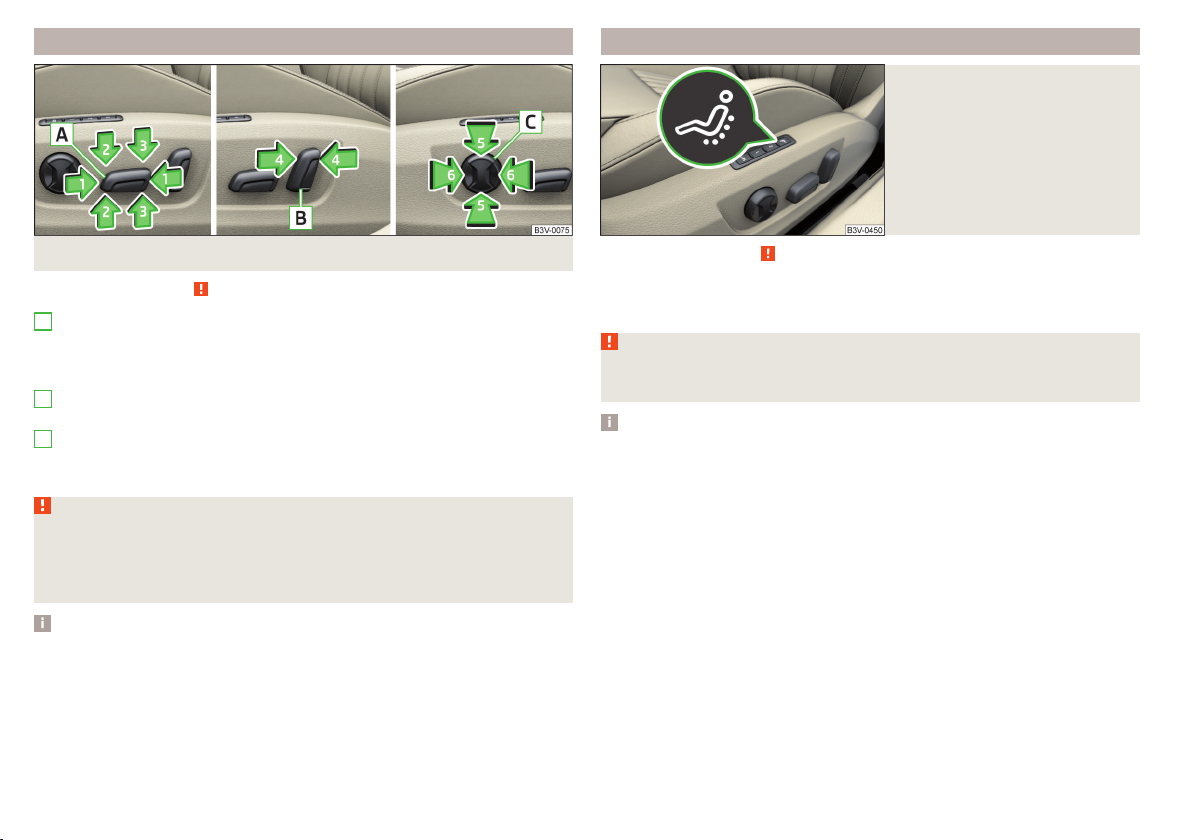
Electrical adjustment
Fig. 87 Control elements on the seat
Read and observe on page 83 first.
A
seat adjustment
▶
1 - Move in the longitudinal direction
▶
2 - Change in inclination
▶
3 - Change in height
B
Adjusting the seat backrest
▶
4 - Change in inclination
C
Adjusting lumbar support
▶
5 - Change curvature
▶
6 - The degree of curvature change
WARNING
The electric front seat adjustment is functional even with the ignition off.
Therefore, when leaving the vehicle, never leave people who are not completely independent, such as children, unattended in the vehicle - there is a
danger of injury!
Driver's seat with massage function
Fig. 88
Button for the massage function
Read and observe on page 83 first.
The massage function is used to massage the lumbar area of the back.
To switch on/off, press the button » Fig. 88.
›
WARNING
Only switch the massage function on and off when the vehicle is stationary
- otherwise there is risk of an accident.
Note
The massage function switches off automatically after approximately 10 minutes.
Note
■
If the inclination angle of the seat backrest relative to the seat surface is
greater than approx. 110°, then it is not possible for safety reasons to save this
setting in the memory of the electrically adjustable seats or the remote control
key.
■
On vehicles with personalisation, the driver's seat setting is stored in the active user account personalisation » page 55.
84
Using the system
Page 87

Convenience operation of the front passenger seat
Fig. 89
Operating elements on the front
passenger's seat
Read and observe on page 83 first.
The front passenger seat can also be operated from the rear seats, by pressing
the respective operating element in the direction of the arrows » Fig. 89.
A
Adjusting the angle of the seat backrest
B
Adjusting a seat in a forward/back direction
Memory Function of the electrically adjustable seat
Fig. 90
SET button and memory buttons
Read and observe on page 83 first.
Among the memory buttons B on the driver's seat, a setting for the driver´s
seat and exterior mirror position can be saved » Fig. 90.
Storing seat and exterior mirror settings for driving forward
Switch on the ignition, adjust the seat and the exterior mirrors, as required.
›
Press the A » Fig. 90 button and then, within 10 seconds, press the de-
›
sired memory button B. Storing is confirmed by an acoustic signal.
Storing front passenger´s exterior mirror settings for reversing
The function for lowering the front passenger's mirror area during reversing
can be activated in Infotainment in the menu
Turn on the ignition and press the desired memory button B » Fig. 90.
›
Turn the rotary knob for the exterior mirror control to the position for the
›
front passenger mirror area » page 82.
Engage reverse gear.
›
Adjust the front passenger's mirror to the desired position.
›
Disengage reverse gear. The set position of the exterior mirror is stored.
›
Retrieving the saved setting
With the ignition off and the driver’s door open-press- the desired memory
›
button B.
In other cases (e.g. if the ignition is switched on or the driver's door closed),
›
hold the button.
Stopping the ongoing adjustment
Press any button on the seat that is to be set. The driver's seat can also be
›
stopped by pressing the button on the radio-operated key.
Note
Every time you save new seat and exterior mirror settings for driving forwards,
you must also save the front passenger mirror setting for reversing again.
/ → →
Mirrors and wipers
.
Memory function of the remote control key
Applies to vehicles that do not have the personalisation function.
Read and observe on page 83 first.
Every time the vehicle is locked, the driver´s seat and exterior mirror settings
are saved and assigned to the key with which the vehicle was locked.
After the following unlocking of the vehicle with the same key and opening the
driver’s door, the driver´s seat and exterior mirrors that are saved to this key
will be adopted.
This function can be used in Infotainment in the menu
vated/deactivated.
Storing front passenger´s exterior mirror settings for reversing
The function for lowering the front passenger's mirror area during reversing
can be activated in Infotainment in the menu
/ → →
/ → →
Mirrors and wipers
Seats
acti-
.
Seats and head restraints
85
Page 88

Unlock the vehicle with the remote control key and switch on the ignition.
›
Turn the rotary knob for the exterior mirror control to the position for the
›
front passenger mirror area » page 82.
Engage reverse gear.
›
Adjust the front passenger's mirror to the desired position.
›
Disengage reverse gear. The adjusted position of the exterior mirror is stored
›
in the remote control key memory.
Stopping the ongoing adjustment
Press any button on the driver's seat or the button on the remote control
›
key.
Folding front passenger seat
WARNING (Continued)
■
Do not adjust the seat backrest while driving - it can cause injury and ac-
cidents!
■
When moving the seat backrest, keep limbs out of the area between the
seat and seat backrest – risk of injury!
■
Never transport the following items on the seat backrest when folded
forwards.
■
Objects that could restrict the driver's view.
■
Objects which make it impossible for the driver to control the vehicle,
e.g. if they roll under the pedals, or could protrude into the driver's zone.
■
Objects which could lead to injury to passengers due to a change of di-
rection or braking manoeuvre when accelerating sharply.
Fig. 91
Folding the front passenger seat
forward
Read and observe on page 83 first.
The front passenger seat can, (depending on equipment fitted), be folded forward into a horizontal position.
To fold down, pull the lever in direction of arrow 1, fold the seat backrest in
›
the direction of arrow 2 » Fig. 91. The locking mechanism must audibly snap
into place.
To fold up, pull the lever in direction of arrow 1, fold back the seat backrest
›
against the direction of arrow 2. The locking mechanism must audibly snap
into place.
Check this by pulling on the seat and on the backrest.
›
WARNING
■
If the seat backrest is folded down, only the seat behind the driver´s seat
can be used to transport passengers.
■
When transporting objects on the folded seat backrest, the front passen-
ger airbag should be deactivated » page 28.
86
Using the system
Armrest setting
Fig. 92
Adjust armrest
Read and observe on page 83 first.
To adjust the height, lift the armrest in the direction of the arrowA into one
›
of the locking positions » Fig. 92.
To close, lift the armrest in the direction of arrow Apast the stop and then
›
fold down again.
Page 89

Rear seats
Seat backrests
Fig. 93 Folding down the seat backrests from the forward from the
passenger compartment
Pull the corresponding lever in the direction of the arrow » Fig. 94. The re-
›
spective seat backrest is unlocked or folded forward.
Folding backwards
Place the outer seat belt behind the raised edge A» Fig. 93.
›
Lift the seat backrest against the direction of arrow 2 until the release lever
›
B
audibly locks. Check this by pulling on the seat backrest.
Make sure that the red pin C is hidden.
›
WARNING
■
The seat backrests in the occupied rear seats must be properly engaged.
■
When transporting objects in the luggage compartment that has been enlarged by folding the backrest forward, ensure the safety of the passengers
transported on the other rear seats.
■
The seat backrests must be securely latched in position so that no objects
from the luggage compartment can slip into the passenger compartment
under sudden braking – risk of injury.
Fig. 94
Fold the backrest forward from
the luggage compartment
Before folding the seat backrests forwards, adjust the position of the front
seats in such a way that they are not damaged by the seat backrests. Remove
the rear headrests if required » page 89.
Folding forwards from the passenger compartment
Place the outer seat belt behind the raised edge A» Fig. 93.
›
Push the release lever B in the direction of arrow 1 and fold down the seat
›
backrest in the direction of arrow 2.
Fold forward from the luggage compartment
On vehicles with a net partition, the left and then the right and middle rear seat
backrest must first be unlocked. The net partition must be rolled up in the
housing.
CAUTION
When operating the seat backrests, the seat belts must not be pinched - there
is a risk of damage to the seat belts.
Fold down armrest
Fig. 95
Fold down armrest
The armrest can be folded down in the direction of the arrow» Fig. 95.
The folded-down armrest can be used as a side table.
Seats and head restraints
87
Page 90

Headrests
Introduction
Note
In sports seats, the headrests are integrated into the seat backrests and cannot be adjusted in height.
Adjust height of front head restraint
Adjusting the rear headrests
Fig. 96
Setting the height of the front
headrest
To adjust the height, hold the locking button A and move the rest in the de-
›
sired direction » Fig. 96.
CAUTION
If the tablet holder adapter is secured to the guide rods of the headrests
» page 103, do not push the headrests down to the stop – risk of damaging the
headrests.
88
Using the system
Fig. 97 Setting the height of the rear headrest
Fig. 98
Fold down side bolsters of the
comfortable headrests
Setting the height
Grasp the headrest and move upwards in the direction of 1 » Fig. 97.
›
To move the restraint down, hold the locking button A in the direction of
›
arrow 2 and push the rest in the direction of arrow 3.
Comfortable headrests
The rear headrests can be equipped with side bolsters. These reduce uncontrolled movement of the head sideways (e.g. when sleeping).
Adjust the headrest to the initial pulled out position » page 88, Adjusting the
›
rear headrests.
Fold down the sides of the head restraint in the direction of arrow » Fig. 98.
›
Page 91

Removing/inserting the rear headrests
Fig. 99 Removing/inserting the rear headrest
To remove, pull the rest out of the seat backrest up to the stop.
›
Hold the locking button A in the direction of arrow 1, at the same time us-
›
ing a flat screwdriver with a max. width of 5 mm to press the locking button
in the opening B in the direction of arrow 2 and pull out the rest in the direction of arrow
To insert, push the rest into the seat backrest in the direction of arrow
›
until the locking button clicks into place.
3
» Fig. 99.
Seat heating and ventilation
Introduction
Buttons for the seat heating and ventilation » Fig. 100
Left seat heating
Right seat heating
Seat heating and ventilation left
Seat heating and ventilation right
The seat heating / ventilation only works when the engine is running.
When the ignition is switched off, the seat heating / ventilation is also switch-
ed off. if the engine is started again within 10 minutes, then the driver's seat
heating / ventilation is switched on again automatically according to the setting before switching off the ignition.
WARNING
If you have a limited pain and / or temperature sensitivity, e.g. due to medication, paralysis or because of chronic illness (e.g. diabetes), we recommend that you do not use the seat heating. If the seat heating is used, we
recommend to make regular breaks in your journey when driving long distances, so that the body can recuperate from the stress of the journey.
4
Please consult your doctor, who can evaluate your specific condition.
CAUTION
The following instructions must be observed to avoid damage to the seats.
■
Do not kneel on the seats or otherwise apply concentrated pressure to them.
■
Do not heat seats that do not contain occupants.
■
Do not heat seats in which objects are secured or resting (e.g. children´s
seat, a bag etc.).
■
Do not heat seats on which additional slipcovers or protective covers are fit-
ted.
Fig. 100
heated rear seats
Depending on the equipment, the front seats can be heated or heated and
ventilated. The outer rear seats can only be heated.
Button arrangement: Heated front seats (and ventilation) /
Seats and head restraints
89
Page 92

Front and rear seats with seat heating
Front seats with heating and ventilation
Fig. 101 The seat heating is switched on at maximum heat: Front
seats/rear seats
Read and observe
To turn on the heating with maximum heat » Fig. 101, press button or .
›
With repeated pressing of the button, the level is down-regulated until it
switches off . The level of the seat heating is indicated by the number of illuminated warning lights underneath / in the button.
Increase in heating power of the rear seat heating can be locked/unlocked.
To do this, press button
on the Infotainment screen (applies to vehicles with Climatronic controls
/
in the rear). In the locked heating power increase, the heating power can only
be adjusted down to turn off.
90
Using the system
and on page 89 first.
on the Climatronic → Tap the function surfaces
Fig. 102 Heating switched on / ventilation switched on / heating and
ventilation are switched on simultaneously
Fig. 103
maximum heating / ventilation level switched on
Press the button or on the control panel of the air conditioner, a menu
›
for operating the front seat heating and ventilation is displayed on the Infotainment screen » Fig. 103.
A
B
Infotainment screen: Front seat heating and ventilation with
Read and observe and on page 89 first.
Function surfaces for setting the ventilation level
Function surfaces for setting the heating power
Functional surfaces for switching off the ventilation (in addition to the
function surfaces
function surfaces B)
A
) or for switching off the heating (in addition to the
Page 93

If the seat heating was switched on before the ignition was switched off, then
pressing the buttons and will switch the seat heating » Fig. 102 on with
maximum output .
If the seat ventilation was switched on before the ignition was switched off,
then pressing the buttons and , will switch the seat ventilation » Fig. 102 on
with maximum ventilation output .
By repeatedly pressing the button or. , the heating or ventilation output is
controlled down to off. The power of the seat heating is indicated by the number of illuminated warning lights underneath the switch.
Only the heating or ventilation can be operated using the buttons or. .
If ventilation and heating are switched on simultaneously on the Infotainment
screen, under each button or. the blue and red warning light illuminates
» Fig. 102 - , the button or. is not functioning (as long as the ventilation
and the heating are switched on simultaneously).
Heated steering wheel
Fig. 104 Steering wheel heating: Manual air conditioning/Climatronic
When the heating is switched on, the symbol in the function surfaceB is orange.
The heated steering wheel only works when the engine is running.
Setting the heating power (applies to the Climatronic)
Press the button on the Climatronic, then tap the function surface →
›
Steering wheel heating on the Infotainment screen.
Setting the heating power.
›
The heating power is displayed by the number of segments in the indicator
light C » Fig. 104.
Steering wheel heating together with the driver's seat heating (applies to
the Climatronic)
To activate / deactivate the heated steering wheel with the driver's seat
›
heating, press the button
face →
To switch on / off the heated steering wheel, press the button for the driver
›
seat heating.
If the heated steering wheel is turned on together with the driver's seat heating, then the function surface is displayed on the Infotainment screen. This
can be used to switch the heated steering wheel off/on.
Link seat/steering wheel heating
on the Climatronic, then tap the function sur-
in the Infotainment screen.
Switching heating on/off (applies to the manual air conditioning)
In the Infotainment system, in menu
›
» Fig. 104.
Switching heating on/off (applies to Climatronic)
Press the button on the Climatronic, then tap the function surface
›
on the Infotainment screen » Fig. 104.
1)
Depending on the equipment, one of the function surface versions is displayed.
/ tap the function surface
A
1)
B
Seats and head restraints
91
Page 94

Practical features
Parking ticket holder
Passenger compartment features
Introduction
WARNING
■
Do not place anything on the dashboard. These objects might slide or fall
down when driving and may distract you from concentrating on the traffic
– risk of accident!
■
Make sure that while driving no objects can enter the driver's footwell cause an accident!
■
Do not carry any objects on the front passenger seat except objects designed for this purpose (e.g. child seats) – risk of accident!
■
No objects should be placed in the storage compartments nor in the
drinks holders; the vehicle occupants could be endangered if there is sudden braking or the vehicle collides with something.
■
For safety reasons, lockable storage compartments must be closed while
driving - there is a risk of injury from the opened cover or from the items in
the compartment.
■
Make sure that no objects protrude from the compartments - there is
danger of injury!
■
Do not exceed the permissible load for the storage compartments and
pockets - it may cause injury or there is the risk of damaging the compartments and pockets!
■
Ash, cigarettes, cigars and the like may only be placed in the ashtray - risk
of fire!
■
The storage compartments and the waste containers are not a substitute
for the ashtray and must also not be used for such purposes – risk of fire!
CAUTION
No not place large or sharp objects in the storage compartments and pockets
- there is a risk of damage to the compartments and pockets.
Fig. 105
Parking ticket holder
Read and observe and on page 92 first.
The ticket holder is provided for the attachment of e.g. parking tickets.
Storage compartment on the driver's side
Fig. 106
To open, lift the handle and fold out the compartment » Fig. 106 .
›
To close, swing the lid against the direction of the arrow until it audibly clicks
›
into place.
A card holder is located in the storage compartment » Fig. 106 .
The maximum permissible load of the storage compartment is 0.5 kg.
Opening the storage compartment / card holder
Read and observe and on page 92 first.
92
Using the system
Page 95

Storage compartments in the doors
Fig. 107 Storage compartments: in the front door/in the rear door
Read and observe and on page 92 first.
Storage compartments » Fig. 107
A
Storage compartment
B
Bottle holder with a capacity of max. 1.5 l
The reflective vest can be stowed in the storage compartments in the door
» page 281.
WARNING
The storage compartment A » Fig. 107n the front door is to be used exclusively for storing objects which do not protrude - there is the danger of
limiting the operating range of the side airbags.
Storage compartment in the front centre console
Read and observe and on page 92 first.
To open, press the ridge in the direction of arrow » Fig. 108 - .
›
To close, press the ridge in the direction of arrow » Fig. 108 - . The lid
›
closes automatically.
Phonebox
Fig. 109
Phonebox
Read and observe and on page 92 first.
The storage compartment in the front centre console can be equipped with
the Phonebox function.
If a phone is placed face up on the pad in the storage compartment » Fig. 109,
the phone signal is amplified by the roof antenna.
Telephones that support the standard for wireless Qi charging can be charged
wirelessly in the storage compartment.
While wireless charging is taking place, no objects may be between the pad
and the telephone being charged.
WARNING
■
The telephone may become warm during wireless charging, so this should
be removed carefully from the tray.
■
Metal objects between the pad and the telephone to be charged can get
hot due to the action of the induction field - There is a risk of injury. If there
is a metal object in the storage compartment that has become hot, then
take out the telephone and let the object cook in the storage compartment!
Fig. 108 Storage compartment: Open/close
Practical features
93
Page 96

CAUTION
■
Metal objects between the pad and the telephone to be charged can get hot
due to the action of the induction field - There is a risk damage to the telephone.
■
With some telephones, the charging process may be interrupted or the telephone may switch off due to getting hot.
■
No electronic or magnetic storage media (e.g. SD cards, USB sticks, cards
with magnetic strips or chip) may be placed between the support and telephone to be charged - there is a risk of data loss and damage to this data carrier.
■
If a message appears in Infotainment that the telephone can not be charged,
then proceed as follows.
■
Check that no objects are between the pad and the telephone being charged. If this is the case, then take out the object and the telephone. Place the
telephone on the pad centrally on the telephone symbol.
■
Check if the position of the telephone to be charged has not changed during the journey. If this is the case, then take out the telephone and place it
back on the pad centrally on the telephone symbol.
Note
■
At the start of the wireless charging process, the appropriate message ap-
pears on the Infotainment screen.
■
For the optimum telephone signal strength and uninterrupted wireless
charging, we recommend position the telephone in the storage compartment
without the protective sleeve, if possible.
■
Place a max. 146x80 telephone in the storage compartment.
USB inputs
Fig. 111
Rear USB inputs
Read and observe and on page 92 first.
The USB input is located in the storage compartment in the center console
and also depending on the equipment fitted, in the storage compartment under the front armrest » Fig. 110.
The USB inputs are also in the rear centre console depending on the equipment fitted » Fig. 111.
The USB input in the storage compartment in the front centre console and in
the storage compartment under the front armrest can be used for charging
and data transfer. The USB inputs in the rear centre console can be used only
for charging.
Information for use » page 153, USB input.
Cup holders
Fig. 110
94
Using the system
Front USB input / USB input under the armrest
Fig. 112 Open front cup holders/ front cup holders
Page 97

Fig. 113 Open rear cup holders/ rear cup holders
Waste container
Read and observe and on page 92 first.
Front cup holder
The cup holder B is located in the front centre console » Fig. 112.
To open, push on the ridge A in the direction of the arrow.
›
To close, pull on the ridge A against the direction of the arrow.
›
In the centre area of the holder
one hand by pushing the container into the holder and turning the lid.
Rear cup holder
Two cup containers can be placed in the cup holder B» Fig. 113.
To open, hold the lid on the recess A and fold in the direction of arrow until
›
the stop.
To close, push the cover against the direction of the arrow.
›
WARNING
■
Do not use any cups or beakers which are made of brittle material (e.g.
glass, porcelain). This could lead to injuries in the event of an accident.
■
Never put hot beverage containers in the cup holder. If the vehicle moves,
they may spill – risk of scalding!
CAUTION
Do not leave open beverage containers in the cup holder during the journey.
There is a risk of spilling e.g. when braking which may cause damage to the
electrical components or seat upholstery.
B
, a beverage container can be opened with
Fig. 114 Waste container: inserting and moving/opening
Fig. 115
The waste container can be inserted into the slot in the door.
Insert waste container
Position the waste container at the front edge of the slot.
›
Push the waste container in the rear area in the direction of the arrow
›
» Fig. 114.
If required, push the waste container in the direction of arrow B.
›
Remove the waste container
Remove the waste container in the opposite direction to the arrow
›
» Fig. 114.
Open/close waste container
Lift the cover in the direction C» Fig. 114.
›
Replace bags
Read and observe and on page 92 first.
Practical features
A
A
95
Page 98
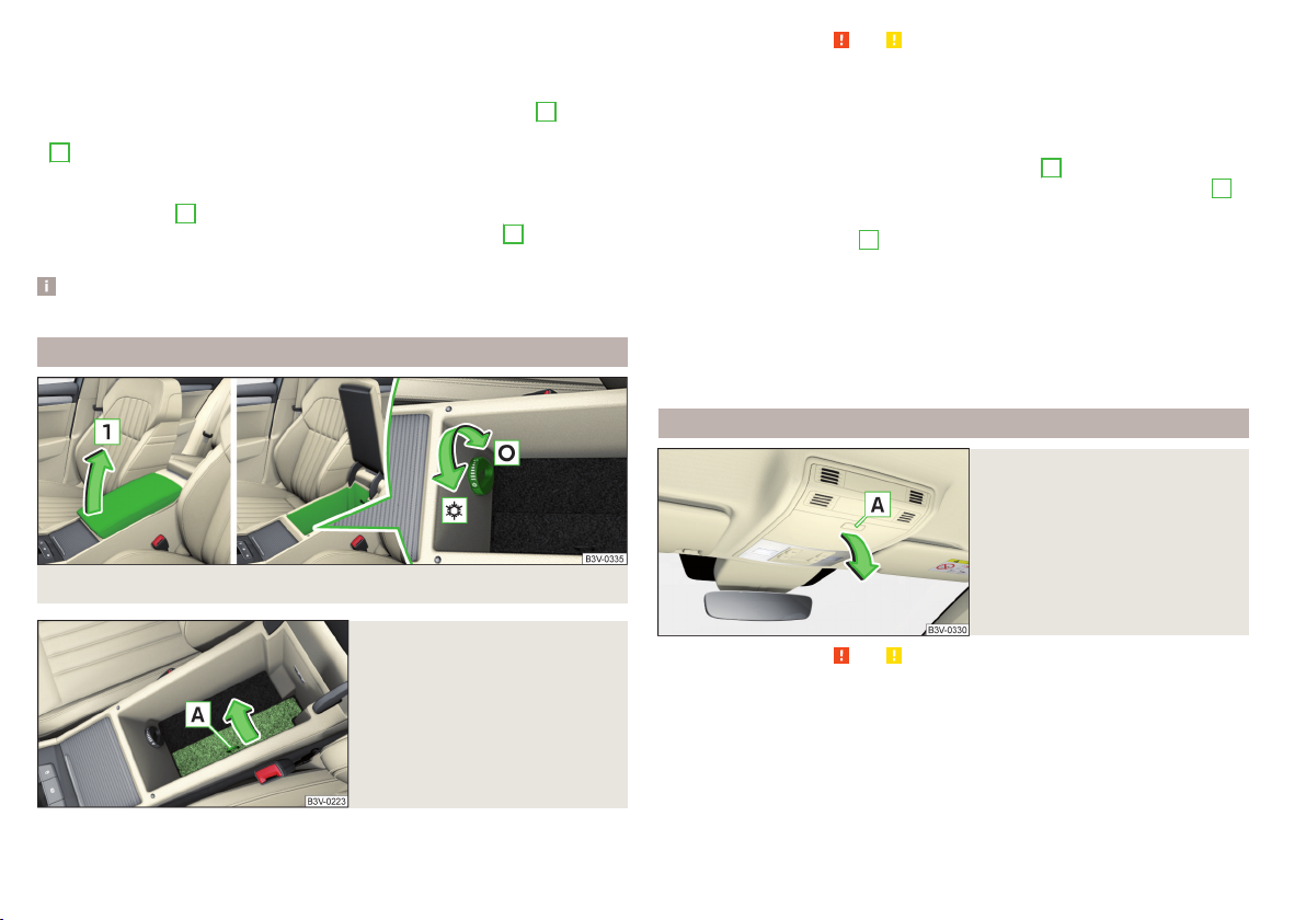
Closing takes place in reverse order.
Replace bags
Remove the waste container from the slot.
›
Press the two locking lugs on the frame in the direction of arrow 1» Fig. 115.
›
Pull the bag together with the frame downwards in the direction of arrow
›
2
.
Remove the bag from the frame.
›
Pull the new bag through the frame and pull it over the bag frame in the di-
›
rection of arrow 3.
Insert the bag containing the frame in the direction of arrow 4 into the con-
›
tainer body, so that the two lugs engage audibly with the frame.
Note
We recommend that you use 20 x 30 cm bags.
Storage compartment underneath the front armrest
Read and observe and on page 92 first.
The storage compartment is equipped with an interior light (this is illuminated
when the parking lights / low beam are switched on), a stowage compartment
for the tablet and an air outlet.
Storage compartment
To open, lift the armrest in the direction of arrow 1» Fig. 116until it stops.
›
To close, fold the armrest down again against the direction of the arrow
›
Storage compartment for the tablet
To open, pull on the loop A in the direction of arrow » Fig. 117.
›
Place the tablet carefully to avoid damage to any connected cables.
›
Air supply
To open, turn the rotary switch until it stops in the position » Fig. 116.
›
To close, turn the rotary switch until it stops in the position .
›
The temperature of the storage compartment supplied with air is dependent
on the setting in the air conditioning.
Glasses storage box
Fig. 118
Opening the glasses storage box
1
.
Fig. 116
96
Using the system
Open tray / control air supply
Fig. 117
Open storage compartment for
the tablet
Read and observe and on page 92 first.
To open, press the -- button. The compartment folds in the direction of the
›
arrow » Fig. 118.
To close, swivel the compartment against the direction of the arrow until it
›
audibly clicks into place.
The maximum permissible load of the glasses compartment is 250 g.
Page 99
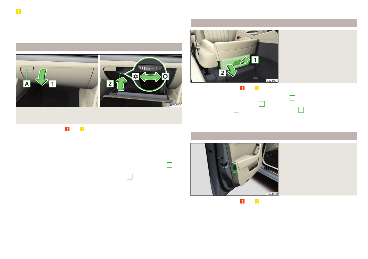
CAUTION
■
Do not put any heat-sensitive objects in the glasses storage box - with high
temperatures there is risk of damage.
■
The box must be closed before leaving and locking the vehicle – risk of im-
pairment to the functions of the anti-theft alarm system.
Storage compartment on the front passenger side
Fig. 119 Open storage compartment / close storage compartment and
open air supply
Read and observe and on page 92 first.
The storage compartment is equipped with an interior light (this is illuminated
when the parking lights / low beam are switched on), a pen holder and an air
outlet.
Storage compartment
To open, press the -- button. The cover folds in the direction of arrow
›
» Fig. 119
To close, swivel the cover in the direction of arrow 2 until it audibly clicks
›
into place.
Air supply
To open, turn the rotary switch until it stops in the position » Fig. 119.
›
To close, turn the rotary switch until it stops in the position .
›
Opening the air supply when the air conditioning system is switched on allows
cooled air to flow into the storage compartment.
Opening the air inlet when the air conditioning system is on causes fresh or interior air to flow into the storage compartment.
.
1
The maximum permissible load of the storage compartment is 3 kg.
Storage compartment under the front passenger’s seat
Fig. 120
Opening the storage compartment
Read and observe and on page 92 first.
To open, pull the handle in direction of arrow 1 pull and open the compart-
›
ment in the direction of arrow 2» Fig. 120.
To close, pull the handle in the direction of arrow 1 and hold this against the
›
direction of arrow 2 until the storage compartment closes.
The maximum permissible load of the storage compartment is 1.5 kg.
Storage compartments for umbrellas
Fig. 121
Storage compartment for an
umbrella - view example in the
left door
Read and observe and on page 92 first.
The storage compartments in the front doors » Fig. 121 can be used to store an
umbrella.
Practical features
97
Page 100

Clothes hook
Storage pockets at the inner sides of the front seats
Fig. 122
Clothes hooks
Read and observe and on page 92 first.
The clothes hooks are located on the middle door pillars of the vehicle and on
the handle of the headliner above each of the rear doors » Fig. 122.
The maximum permissible load of each of the hooks is 2 kg.
WARNING
■
Never leave any heavy or sharp-edged objects in the pockets of the items
of clothing hung up.
■
To hang the clothes do not use hangers - there is a risk of limiting the effectiveness of head airbags.
■
Ensure that any clothes hanging from the hooks do not impair your vision
to the outside.
Storage pockets on the backs of the front seats
Fig. 123
Map pockets
Read and observe and on page 92 first.
The map pockets are intended for storage of maps, magazines, etc.
Fig. 124
Storage pocket
Read and observe and on page 92 first.
The storage pockets are located on the inside of the driver, if necessary, also
the front passenger seat » Fig. 124 and are used to store small and light objects
(e.g. mobile telephones).
The maximum permissible load of each of the pockets is 200 g.
Storage compartment in rear centre console
Fig. 125
Open storage compartment,
open lockable storage compartments
Read and observe and on page 92 first.
In the rear centre console there is an equipment-dependent open storage
compartment
To open, pull the storage compartment B on the upper part of the recess
›
and fold down the compartment in the direction of arrow » Fig. 125.
To close, swivel the compartment against the direction of the arrow.
›
There is a cushioned insert in the storage compartment. This can be removed
if the storage compartment is opened to the stop.
A
and a lockable storage compartment B» Fig. 125.
98
Using the system
 Loading...