

Page 1
SIMPLY CLEVER
OWNER´S MANUAL
OWNER´S MANUAL
ŠKODA Superb
Page 2

Page 3

Preface
You have opted for a ŠKODA – our sincere thanks for your confidence in us.
This Owner's Manual contains instructions about the vehicle operation, important information about
safety, vehicle care, maintenance and self-help and technical vehicle data.
The operation of some functions and vehicle systems is undertaken via Infotainment.
Please do not read just this manual, but also the Infotainment Owner's Manual carefully as well. The
procedure in accordance with the two instructions is a prerequisite for the correct use of the vehicle.
When using the vehicle, the universally applicable country-specific legal requirements (e.g. for trans-
porting children, deactivating the airbag, tyre use, road traffic etc.) must always be observed.
We hope you enjoy driving your ŠKODA, and wish you a pleasant journey at all times.
Your ŠKODA AUTO a.s. (hereinafter referred to as ŠKODA or manufacturer)
Page 4

Table of Contents
On-board literature 4
Notes 5
Structure and more information about the
Owner's Manual 6
Abbreviations
Safety
Passive Safety 8
General information 8
Correct and safe seated position 8
Seat belts 11
Using seat belts 11
Belt retractors and belt tensioners, reversible
seat belts 13
Airbag system 14
Description of the airbag system 14
Airbag overview 15
Deactivating airbags 19
Transporting children safely 20
Child seat 20
Fastening systems 23
Using the system
Cockpit 27
Overview
Instruments and warning lights
Instrument cluster
Warning lights
Information system
Driver information system
Driving data (Multifunction display)
26
28
28
42
MAXI DOT display 45
Service interval display 49
SmartGate 50
Unlocking and opening 52
Unlocking and locking 52
Anti-theft alarm system 57
Luggage compartment lid 58
Electric boot lid 59
Window operation 61
Panorama sliding/tilting roof 64
Lights and visibility 67
Lights 67
Headlamp Assistant (Light Assist / Dynamic
Light Assist) 72
Interior lights 74
Visibility 75
Windscreen wipers and washers 77
Rear mirror 79
Seats and head restraints 81
Front seats 81
Rear seats 85
Head restraints 87
Seat heating and ventilation 88
Transporting and practical equipment 90
Useful equipment 90
Electrical sockets and cigarette lighter 99
Ashtrays 103
Tablet holder 104
Luggage compartment and transport of
cargo 105
Variable loading floor in the luggage
compartment (Estate) 115
31
41
41
Net partition 116
Roof rack 117
Heating and ventilation 118
Heating, manual air conditioning system,
Climatronic 118
Auxiliary heating (auxiliary heating and
ventilation) 123
Driving
Starting-off and Driving 126
Starting and stopping the engine using the
key 126
Starting and stopping the engine at the push
of the button 128
START-STOPsystem 130
Brakes and parking 132
Manual gear changing and pedals 135
Automatic transmission 135
Running-in and economical driving 138
Avoiding damage to your vehicle 141
Assist systems 142
General information 142
Braking and stabilisation systems 143
Parking aid (ParkPilot) 147
Rear Traffic Alert 149
Rear View Camera 151
Park Assist 155
Cruise Control System 160
Speed Limiter 162
Adaptive Cruise Control (ACC) 163
Front Assist 168
Selection of the driving mode(Driving Mode
Selection) 171
Proactive passenger protection (Crew Protect
Assist) 173
Lane Departure Warning (Lane Assist) 174
Assistant for “blind spot monitoring” 177
2
Table of Contents
Page 5

Traffic jam assistant 179
Assistant for emergencies 179
Traffic sign recognition 180
Fatigue detection 182
Tyre pressure monitoring 183
Hitch and trailer 184
Hitch 184
Trailer 185
General Maintenance
Care and maintenance 190
Service work, adjustments and technical
alterations 190
Washing vehicle 193
Cleaning vehicle exterior 194
Interior care 198
Inspecting and replenishing 201
Fuel 201
AdBlue® and its refilling 204
Engine compartment 206
Engine oil 209
Coolant 210
Brake fluid 212
Vehicle battery 213
Wheels
Tyres and wheel rims 217
Winter operation 220
217
Emergency unlocking/locking 235
Replacing windscreen wiper blades 237
Fuses and light bulbs 238
Fuses 238
Bulbs 242
Technical data
Technical data 246
Basic vehicle data 246
Vehicle-specific information depending on
engine type 252
Index
Do-it-yourself
Emergency equipment and self-help
Emergency equipment 222
Changing a wheel 224
Puncture repair kit 228
Jump-starting 230
Towing the vehicle 231
Remote control and removable light 233
222
Table of Contents
3
Page 6

On-board literature
You will always find this Owner's Manual and the Service Plan included in the
on-board literature for your vehicle.
Depending on the equipment, the on-board literature can also include the In-
fotainment Owner´s Manualand in some countries also the brochure On the
road.
Owner's Manual
These Owner´s Manual apply to all body variants of the vehicle and all related
model versions as well as all equipment levels.
This Owner's Manual describes all possible equipment variants without identifying them as special equipment, model variants or market-dependent equipment. Consequently, this vehicle does not contain all of the equipment com-
ponents described in this Owner's Manual.
The level of equipment in your vehicle refers to your purchase contract for the
vehicle. For any questions regarding the scope of equipment, please contact a
ŠKODA Partner.
The Pictures in this Owner's Manual are for illustrative purposes only. The illustrations can differ in minor details from your vehicle; they are only intended
to provide general information.
ŠKODA AUTO a.s. pursues a policy of ongoing product and model development
with all vehicles. Changes in terms of supply scope are possible at any time
with regard to design, equipment and technology. The information listed in
this Owner's Manual corresponds to the information available at the time of
going to press.
Therefore legal claims cannot be made based on the technical data, illustrations and information contained in this Owner's Manual.
We recommend that the web pages that are referred to in this Owner's Manual are displayed using the classic view. If the web pages are displayed using
the mobile view, they may not contain all necessary information.
Service schedule
The service schedule includes the documentation of the vehicle handover,
warranty information and service events.
Infotainment Owner´s Manual
The Infotainment Owner's Manual contains a description of the Infotainment
service and possibly also some functions and vehicle systems.
On-the-road brochure
The On The Move brochure contains the importer's customer service number
and the service number in the individual countries as well as the emergency
numbers.
Online user manuals
Fig. 1
This QR code opens a web page with a model overview of the ŠKODA brand.
The page can also be accessed by entering the following address in the web
browser.
http://www.skoda-auto.com/en/mini-apps/owners-manuals/
▶
Select the desired model - a menu with the user manuals is displayed.
▶
Select the construction period as well as the language.
▶
Select the desired manual - it can be displayed either online or in pdf format.
4
On-board literature
Page 7

Notes
Terms used
The on-board literature contains the following terms relating to the service
work for your vehicle.
“Specialist”
“ŠKODA service partner”
“ŠKODA partner”
Explanation of symbols
An overview of the symbols used in the Owner's Manual and a brief explanation of their meaning.
Continuation of the module on the next page
Situations in which the vehicle must be stopped as soon as possible
® Registered trademark
Telephone operation in the MAXI DOT display
Text display in the segment display
Texts with this symbol draw attention to threats of a serious accident, injury or loss of life.
- Workshop - a workshop that carries out specialist service tasks
for ŠKODA vehicles. A specialist can be a ŠKODA Partner, a ŠKODA Service Partner, or an independent workshop.
- a workshop that has been contractually authorised
by the manufacturer or its sales partner to perform service tasks on
ŠKODA vehicles and to sell ŠKODA Genuine Parts.
- a company that has been authorised by the manufacturer
or its sales partner to sell new ŠKODA vehicles and, when applicable, to
service them using ŠKODA Genuine Parts and sell ŠKODA Genuine Parts.
Reference to the introductory module of a chapter with important information and safety warnings
WARNING
Note
Texts with this symbol contain additional information.
CAUTION
Texts with this symbol draw attention to the risk of vehicle damage or possible
inoperability of some systems.
For the sake of the environment
Texts with this symbol contain information on environmental protection as
well as tips for economical operation.
Notes
5
Page 8

Structure and more information about the Owner's Manual
Structure of the manual
The Owner's Manual is hierarchically divided into the following areas.
■
Section (e.g. Safety) - the title of the Section is always indicated at the lower
left side
■
Main chapters (e.g. Airbag system) - the title of the main chapter is always
indicated at the lower right side
■
Chapter (e.g. Airbag overview)
■
Introduction to the topic – Module Overview within the chapter, in-
troductory information about the chapter content, notes that apply to
the entire chapter, if relevant
■
Module (e.g. Front airbags)
Information search
When searching for information in the Owner´s Manual, we recommend using
the Index at the end of the Owner's Manual.
Direction indications
All direction indications such as “left”, “right”, “front”, “rear” relate to the forward direction of travel of the vehicle.
Units
The volume, weight, speed and length data are given in metric units, unless
otherwise indicated.
Display
In this Owner's Manual, the MAXI DOT display is used as the display in the instrument cluster unless otherwise stated.
6
Structure and more information about the Owner's Manual
Page 9

Abbreviations
Abbreviation Definition
rpm Engine revolutions per minute
ABS Anti-lock brake system
ACC Adaptive cruise control
ACT active cylinder management
AF Multi-purpose vehicles
AGM Vehicle battery type
APN An access point name for the WLAN connection
TCS Traction control
CO
COC Declaration of conformity
DCC adaptive chassis control
DPF Diesel particle filter
DSG Automatic double clutch gearbox
DSR Active driver-steering recommendation
EDL Electronic differential lock
ECE Economic Commission for Europe
EPC EPC fault light
ESC Electronic Stability Control
ET Rim depth
EU European Union
GSM Global system for mobile communications
HBA Hydraulic brake assist
HHC Uphill start assist
KESSY Keyless unlocking, starting and locking
kW Kilowatt, measuring unit for output
LED Lighting element type
M1
MCB Multi-collision brake
MG Manual gearbox
Carbon dioxide
2
A passenger car constructed primarily for the transport of
people
Abbreviation Definition
N1
NiMH Nickel metal hydride
Nm Newton meter, measuring unit for the engine torque
PIN personal identification number
SCR Diesel engine for which the AdBlue ® solution is required
SSP Connect two devices using Bluetooth® profile
TDI CR
TSA Trailer stabilisation
TSI Petrol engine with turbo charging and direct injection
VDA Association of the Automotive Industry (in Germany)
VIN Vehicle identification number
W Watt, unit of power
WLAN Wireless data network
XDS Functional extension of the electronic differential lock
Panel van intended exclusively or mainly for the transportation of goods
Diesel engine with turbo-charging and common rail injection
system
Abbreviations
7
Page 10

Safety
Passive Safety
General information
Introduction
This chapter contains information on the following subjects:
Before setting off
Driving safety 8
In this section of the instructions you will find important information, tips and
notes on the subject of passive safety.
We have combined everything here which you should be familiar with, for example, regarding seat belts, airbags, safety of children and anything similar.
You can find further information on safety concerning you and those travelling
with you in the following chapters of this Owner's Manual.
The complete on-board literature should therefore always be in the vehicle.
This applies in particular, if you rent out or sell the vehicle.
Before setting off
For your own safety and the safety of the people travelling with you, please
pay attention to the following points before setting off.
▶
Ensure that the lighting and the turn signal system are functioning properly.
▶
Ensure that the function of the wipers and the condition of the wiper blades
are free of any defects.
▶
Ensure that all of the windows offer good visibility to the outside.
▶
Adjust the rear-view mirror so that vision to the rear is guaranteed.
▶
Ensure that the mirrors are not covered.
▶
Check the tyre inflation pressure.
▶
Check the engine oil, brake fluid and coolant level.
▶
Secure all items of luggage.
▶
Do not exceed the permissible axle loads and permissible gross weight of the
vehicle.
▶
Close all doors as well as the bonnet and boot lid.
▶
Ensure that no objects can obstruct the pedals.
▶
Protect children in suitable child seats with correctly fastened seat belts
» page 20, Transporting children safely.
▶
Adopt the correct seated position » page 8, Correct and safe seated position. Tell your passengers to assume the correct seated position.
Driving safety
The driver is fully responsible for himself and passengers, especially children. If
your driving safety is effected, you place yourself and the oncoming traffic at
risk.
8
The following guidelines must therefore be observed.
▶
Do not become distracted from concentrating on the traffic situation, (e.g. by
your passengers or mobile phone calls).
▶
Never drive when your driving ability is impaired, (e.g. due to medication, alcohol or drugs).
▶
Keep to the traffic regulations and the permissible speed limit.
▶
Always adjust the driving speed to the road, traffic and weather conditions.
▶
Take regular breaks on long journeys (at least every two hours).
The following list contains instructions for the Passenger which, if not observed, may cause serious injuries or death.
▶
Do not lean against the dash panel.
▶
Do not put your feet on the dash panel.
The following list contains instructions for all Passengers which, if not observed, may cause serious injuries or death.
▶
Do not sit only on the front part of the seat.
▶
Do not sit facing to the side.
▶
Do not lean out of the window.
▶
Do not put your limbs out of the window.
▶
Do not put your feet on the seat cushion.
Correct and safe seated position
Introduction
This chapter contains information on the following subjects:
Correct seat position of the driver 9
Adjusting the steering wheel position
Correct seated position for the front passenger
Correct seated position for the passengers in the rear seats
9
10
10
8
Safety
Page 11
WARNING
■
The front seats and all head restraints must be adjusted to match the
body size at all times and the seat belt must always be fastened properly to
provide the most effective levels of protection to the passengers.
■
Each occupant must correctly fasten the seat belt belonging to the seat.
Children must be fastened » page 20, Transporting children safely with a
suitable restraint system.
■
By sitting incorrectly, the occupant is risking life-threatening injuries.
■
The seat backrests must not be tilted too far back when driving, as this
will impair the function of the seat belts and of the airbag system – risk of
injury!
Correct seat position of the driver
Adjust the head restraint so that the top edge of the head restraint is at
the same level as the upper part of your head C » Fig. 2 (not for seats
with integrated head restraint).
Correctly fasten the seat belt » page 11, Using seat belts.
WARNING
■
Always assume the correct seated position before setting off and do not
change this position while driving. Also advise your passengers to adopt
the correct seated position and not to change this position while the car is
moving.
■
Maintain a distance of at least 25 cm from the steering wheel, and a distance of at least 10 cm between the legs and the dash panel at the height
of the knee airbag. Not maintaining this minimum distance will mean that
the airbag system will not be able to properly protect you - hazard!
■
When driving, hold the steering wheel with both hands firmly on the outer edge in the “9 o'clock” and “3 o'clock” position » Fig. 2. Never hold the
steering wheel in the “12 o'clock” position or in any other way (e.g. in the
middle, inner edge of the steering wheel or similar). In such cases, you
could severely injure the arms, hands and head when the driver airbag is
deployed.
■
Ensure that there are no objects in the driver's footwell, as these may get
caught in the pedal apparatus when driving or braking. You would then no
longer be able to operate the clutch, brake or acceleration pedals.
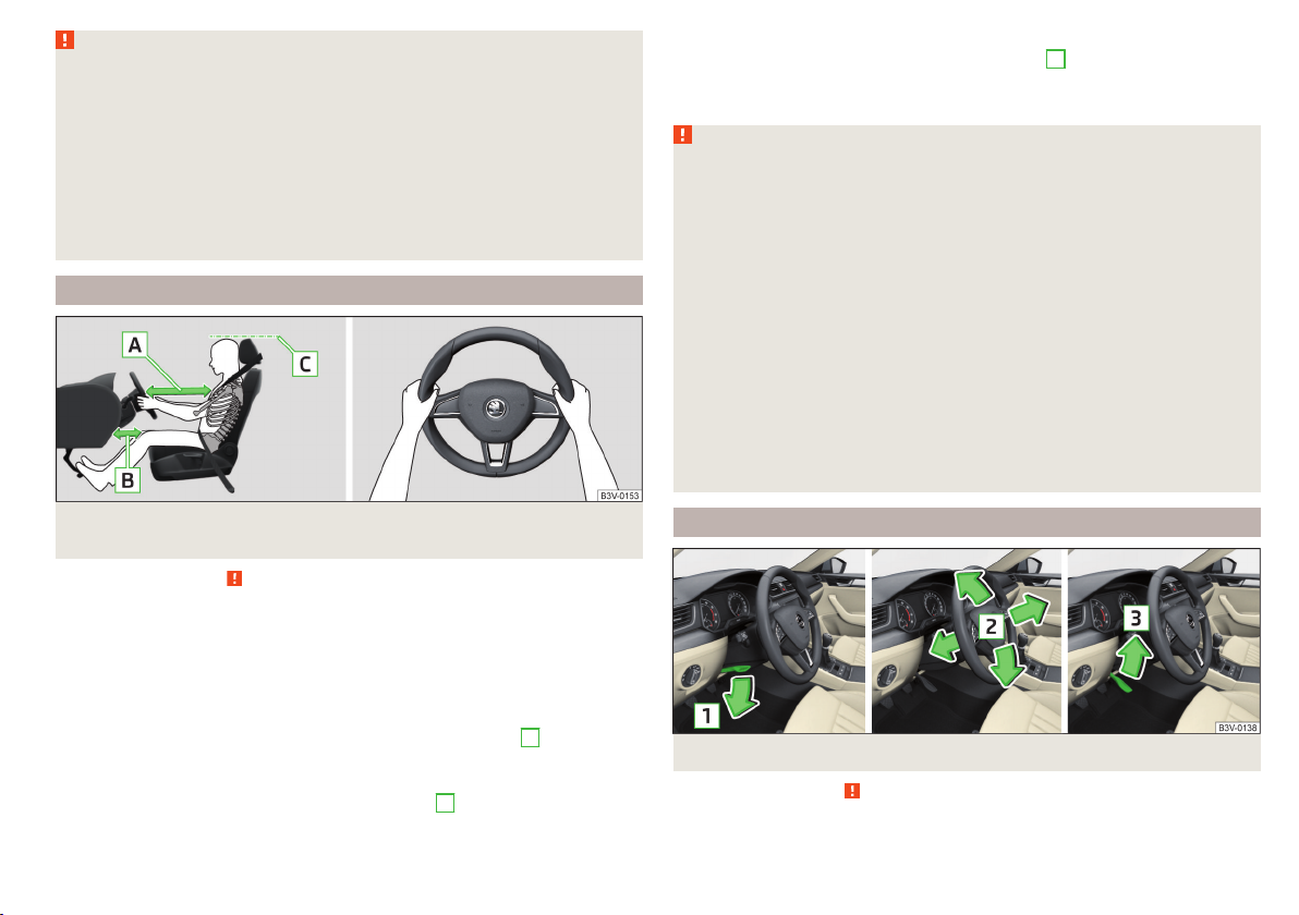
Fig. 2 Correct seated position for the driver/correct steering wheel posi-
tion
Read and observe
on page 9 first.
For your own safety and to reduce the risk of injury in the event of an accident,
the following instructions must be observed.
Adjust the driver’s seat in the forward/back direction so that the pedals
can be fully depressed with slightly bent legs.
For vehicles with driver knee air-bag adjust the driver's seat in a for-
ward/back direction so that there is a gap of at least 10 cm between the
legs and the dash panel in the vicinity of the knee airbag - B » Fig. 2.
Adjust the seat backrest so that the highest point of the steering wheel
can be reached with your arms at a slight angle.
Adjust the steering wheel so that the distance A between the steering
wheel and your chest is at least 25 cm » Fig. 2.
Adjusting the steering wheel position
Fig. 3 Adjusting the steering wheel position
Read and observe on page 9 first.
The height and forward/back position of the steering wheel can be adjusted.
Passive Safety
9
Page 12

Swing the safety lever under the steering wheel in the direction of arrow
›
» Fig. 3.
Adjust the steering wheel to the desired position. The steering wheel can be
›
adjusted in direction of arrow 2.
Pull the holder in arrow direction 3 until the stop.
›
WARNING
■
Never adjust the steering wheel when the vehicle is moving only when
the vehicle is stationary!
■
The safety lever must be locked so that the steering wheel cannot acci-
dentally change position – risk of accident!
1
Correct seated position for the front passenger
Read and observe on page 9 first.
For passenger safety and to reduce the risk of injury in an accident, the following instructions must be observed.
Position the front passenger seat back as far as possible. The front passenger must maintain a distance of at least 25 cm to the dash panel so
that the airbag offers the greatest possible safety if it is deployed.
Adjust the head restraint so that the top edge of the head restraint is at
the same level as the upper part of your head C » Fig. 2 on page 9 (not for
seats with integrated head restraint).
Correctly fasten the seat belt » page 11.
In exceptional cases the front passenger airbag can be deactivated
» page 19, Deactivating airbags.
WARNING
■
Maintain a distance of at least 25 cm to the dash panel. Not maintaining
this minimum distance will mean that the airbag system will not be able to
properly protect you - hazard!
■
Always keep your feet in the footwell when the car is being driven – never place your feet on the instrument panel, out of the window or on the
surface of the seats! You will be exposed to increased risk of injury if it becomes necessary to apply the brake or in the event of an accident. If an airbag is deployed, you could suffer fatal injuries by adopting an incorrect
seated position!
Correct seated position for the passengers in the rear seats
Read and observe on page 9 first.
To reduce the risk of injury in the event of a sudden braking manoeuvre or an
accident, the occupants on the rear seats must observe the following.
Adjust the head restraint so that the top edge of the head restraint is at
the same level as the upper part of the head C » Fig. 2 on page 9.
Correctly fasten the seat belt » page 11, Using seat belts.
Use a suitable child restraint system if transporting children in the vehicle
» page 20, Transporting children safely.
10
Safety
Page 13

Seat belts
Using seat belts
Introduction
This chapter contains information on the following subjects:
The physical principle of a head-on collision 12
Correct routing of seat belt 12
Fastening and unfastening seat belts 13
Seat belts that are fastened correctly offer good protection in the event of an
accident. They reduce the risk of an injury and increase the chance of survival
in the event of a major accident.
Properly fastened seat belts hold occupants to correctly set seats in the right
seat position.
Particular safety aspects must be observed when transporting children in the
vehicle » page 20.
WARNING
■
Fasten your seat belt before each journey - even when driving in town!
This also applies to other passengers - there is a danger of injury!
■
Maximum seat belt protection is only achieved if you are correctly seated
» page 8, Correct and safe seated position.
■
The seat backrests of the front seats must not be tilted too far to the rear
otherwise the seatbelts can lose their effectiveness.
WARNING
Information on the correct routing of the belt
■
Always ensure that the webbing of the seat belts is properly routed. Seat
belts which are not correctly adjusted can themselves cause injuries even
in minor accidents.
■
Adjust the height of the belt in such a way that the shoulder part of the
belt is roughly positioned across the middle of your shoulder - on no account across your neck.
WARNING (Continued)
■
A seat belt which is hanging too loose can result in injuries as your body is
moved forward by the kinetic energy produced in an accident and is then
suddenly held firm by the belt.
■
The belt webbing must not run across solid or fragile objects (e.g. spectacles, ball-point pens, bunches of keys etc.). Such objects can cause injury.
WARNING
Information on dealing with the safety belts
■
The belt webbing must not be jammed in-between at any point or twisted, or chafe against any sharp edges.
■
Make sure you do not catch the seat belt in the door when closing it.
WARNING
Information on the proper use of safety belts
■
No two persons (also not children) should ever use a single seat belt together.
■
The lock tongue should only be inserted into the lock which is the correct
one for your seat. Wrong use of the safety belt will reduce its capacity to
protect and the risk of injury increases.
■
The slot of the belt tongue must not be blocked, otherwise the belt
tongue will not lock in place properly.
■
Many layers of clothing and loose clothing (e. g. a winter coat over a jacket) do not allow you to be correctly seated and impairs proper operation of
the seat belts.
■
Do not use clamps or other objects to adjust seat belts (e.g. for shortening the belts for smaller persons).
■
The seat belts for the rear seats can only fulfil their function reliably
when the seat backrests are correctly locked into position » page 85.
WARNING
Information on the care and maintenance of safety belts
■
The belt webbing must always be kept clean. Soiled belt webbing may impair proper operation of the inertia reel » page 200.
■
The seat belts must not be removed or changed in any way. Do not attempt to repair the seat belts yourself.
Seat belts
11
Page 14
WARNING (Continued)
■
Check the condition of all the seat belts on a regular basis. If any damage
to the seat belts, seat belt connections, inertia reel or the lock is detected,
the relevant seat belt must be replaced by a specialist garage.
■
Damaged seat belts which have been subjected to stress in an accident
and were therefore stretched, must be replaced – this is best done by a
specialist garage. The anchorage points of the belts must also be inspected. The anchorage points for the belts should also be checked.
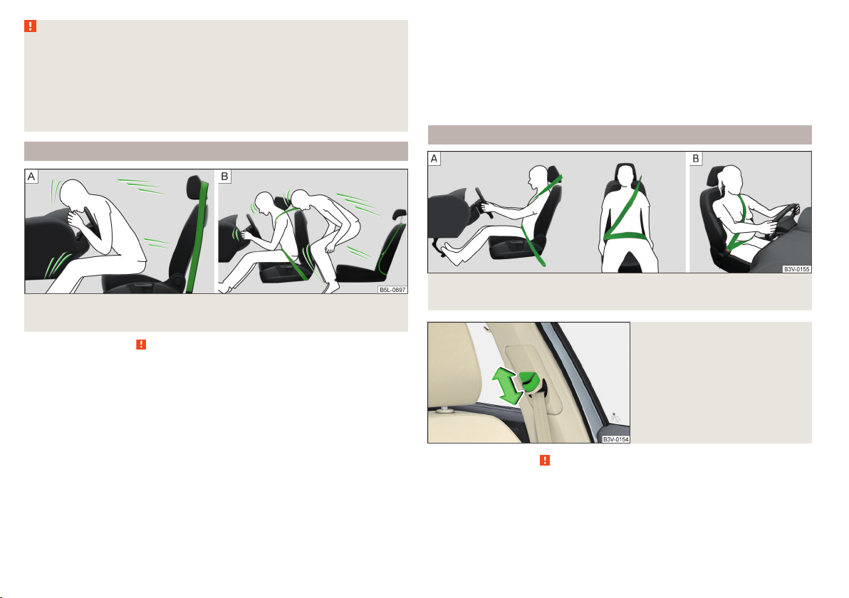
The physical principle of a head-on collision
Fig. 4 Driver without a fastened seat belt/rear seat passenger without a
fastened seat belt
Read and observe on page 11 first.
As soon as the vehicle is moving, so-called kinetic energy (the energy of motion) is produced, both in terms of the car as well as in terms of the occupants.
The magnitude of this kinetic energy depends essentially on the speed at
which the vehicle is travelling and on the weight of the vehicle including the
occupants.
Doubling the speed of the vehicle from 25 km/h up to 50 km/hour increases
the kinetic energy four times.
For example, a person's weight of 80 kg “increases” to 4.8 tons (4800 kg) at
50 km/h.
In the event of a frontal collision, occupants of the car not wearing a seat belt
are thrown forward and strike parts of the interior of the car, such as the
steering wheel, dash panel, windscreen in ways which cannot be controlled
» Fig. 4 - . In certain circumstances you could even be thrown out of the vehi-
cle, which could cause life threatening or even fatal injuries.
Rear seat passengers who have not fastened their seat belts are a danger not
only to themselves but also to those seated at the front » Fig. 4 – .
Correct routing of seat belt
Fig. 5
Routing of belt webbing over the shoulders and the lap belt/Rout-
ing of belt webbing for an expectant mother
Fig. 6
Front seat: Seat belt height adjuster
Read and observe on page 11 first.
It is important that the belt is properly routed to ensure seat belts offer the
maximum protection.
12
Safety
Page 15

The shoulder part of the seat belt must never run across the neck but must
roughly run over the middle of the shoulder and fit snugly against the chest.
The lap part of the belt must run across the pelvis, must not be positioned
across the stomach and must always fit snugly » Fig. 5 - .
seat belt height adjusters for front seats
The seat belt height adjuster makes it possible to adjust the routing of the
front seat belts in the area of the shoulder to the body size.
Press the height adjuster and move to the desired position » Fig. 6.
›
Then pull firmly on the belt to ensure that the seat belt height adjuster has
›
correctly locked in place.
Seat belts with pregnant women
Expectant women must also always wear a seat belt. This is the only way of
ensuring optimal protection for the unborn child.
With pregnant women, the lap part of the belt must be positioned as low as
possible on the pelvis to avoid exerting any pressure on the lower abdomen
» Fig. 5 - .
Fastening and unfastening seat belts
Fig. 7 Fastening/unfastening the seat belt
Read and observe on page 11 first.
Before using the seat belts the following conditions must be met.
Correctly set head restraint (not for seats with integrated head restraint).
Correctly adjusted seat (applies for the front seats).
Correctly adjusted steering wheel (applies to the Driver's seat ).
Fasten
Use the lock tongue to slowly pull the webbing over your chest and pelvis.
›
Insert the lock tongue into the belt buckle for the seat » Fig. 7 - until it
›
audibly clicks into place.
Pull on the belt to check that it has engaged correctly in the lock.
›
Release
Release the seat belt only when the vehicle is stationary.
Press the red button in the belt buckle » Fig. 7 - ; the lock tongue pops out.
›
Manually guide the belt back so that it is easier to fully roll up the webbing,
›
the seat belt does not twist.
CAUTION
When releasing the seatbelt ensure that the tongue of the lock does not damage the door trim or other parts of the interior.
Belt retractors and belt tensioners, reversible seat belts
Introduction
This chapter contains information on the following subjects:
Inertia reel 13
Belt tensioners
Reversible seat belts
Inertia reel
Each seat belt is equipped with an inertia reel. When pulling slowly on the seat
belt, the belt can move freely.
When pulling sharply on the seat belt, the movement is locked by the inertia
reel. The belts also lock when full braking, when the car accelerates, when
driving downhill and when cornering.
WARNING
If the seat belt does not lock when pulling sharply on it, have it inspected
immediately by a specialist garage.
14
14
Seat belts
13
Page 16

Belt tensioners
The safety for the driver, front passenger and passengers on the outer rear
seats who are wearing their seat belts, is enhanced by the belt tensioners fitted to the inertia reels on the front and rear external seat belts.
If there is a collision with a certain severity the seat belts are tightened by the
belt tensioner so that unwanted body motion is prevented.
Belt tensioners are not activated in the event of minor collisions, in the case
of a roll-over and also not in accidents in which no major forces are produced.
WARNING
■
Any work on the belt tensioner system including removal and installation
of system components because of other repair work, must only be carried
out by a specialist garage.
■
The protective function of the system is only adequate for a single accident. If the belt tensioners have been deployed, it is then necessary to replace the entire system.
Note
■
The belt tensioners can also be deployed if the seat belts are not fastened.
■
Smoke is generated when the belt tensioners are deployed. This is not an in-
dication of a fire in the vehicle.
Reversible seat belts
Safety for the driver and front passenger wearing their seat belts is enhanced
by reversible seat belts.
Reversible seat belts are automatically tensioned in critical driving situations
tightly over the body and then released again.
Further information » page 173, Proactive passenger protection (Crew Protect
Assist).
Airbag system
Description of the airbag system
Introduction
This chapter contains information on the following subjects:
System description 15
Airbag deployment 15
The airbag system supplements the fastened seat belts and provides additional occupant protection in severe frontal and side collisions.
The functional status of the airbag system is indicated by the warning light
in the instrument cluster » page 35.
WARNING
■
An airbag can only offer you optimal protection in combination with a
fastened seat belt.
■
The airbag is not a substitute for the seat belt, but instead forms part of
the complete passive vehicle safety concept.
■
To ensure passengers are protected with the greatest possible effect
when the airbag is deployed, the front seats must be correctly adjusted to
match the body size » page 8, Correct and safe seated position.
■
If you do not fasten the seat belts when driving, lean too far forward or
adopt an incorrect seated position, you are exposing yourself to increased
risk of injury in the event of an accident.
WARNING
Information on the use of the airbag system
■
If there is a fault, have the airbag system checked immediately by a specialist garage. Otherwise, there is a risk of the airbag not being activated in
the event of an accident.
■
No modifications of any kind must be made to parts of the airbag system.
■
Any work on the airbag system including the installation and removal of
system components due to other repair work (e.g. removal of the steering
wheel) must only be carried out by a specialist garage.
■
Never make any changes to the front bumper or the bodywork.
■
Do not manipulate individual parts of the airbag system, as this might result in the airbag being deployed.
■
The airbag system must then be replaced if the airbag has been deployed.
14
Safety
Page 17
System description
Read and observe on page 14 first.
The inflation of the airbag is carried out in a fraction of a second.
When the airbags are deployed, they fill with gas and inflate.
A grey white or red, non-harmful gas is released when the airbag is inflated.
This is perfectly normal and is not an indication of a fire in the vehicle.
Depending on the vehicle equipment, the airbag system consists of the
following parts.
▶
Front airbag for the driver and the front passenger » page 15.
▶
Driver’s knee airbag » page 17.
▶
Side airbags » page 17.
▶
Head airbags » page 18.
▶
Airbag warning light in the instrument cluster » page 35.
▶
Key switch for the front passenger airbag » page 19.
▶
Warning light for the front passenger airbag in the middle of the dash panel
» page 19.
Airbag deployment
Read and observe
The airbag system is only functional when the ignition is switched on.
Triggering conditions
It is not possible to generally determine which deployment conditions apply to
the airbag system in every situation. An important role is played by factors
such as the type of object that the vehicle hits (hard/soft), the impact angle,
vehicle speed etc.
A decisive factor for the deployment of the airbags is the deceleration which
occurs. If the vehicle deceleration which occurs and is measured during the
collision remains below the prescribed reference values specified in the control
unit, the airbags are not deployed although the vehicle may well suffer severe
damage to the bodywork as a consequence of the accident.
The following airbags will be deployed in the event of a severe frontal
collision.
▶
Driver’s front airbag.
▶
Front passenger airbag.
▶
Driver’s knee airbag.
on page 14 first.
The following airbags will be deployed in the event of a severe side collision.
▶
Front side airbag on the side of the accident.
▶
Rear side airbag on the side of the accident.
▶
Head airbags on the side of the accident.
When an airbag is deployed, the following events occur.
▶
The interior light comes on (if the automatic operation of the interior light is
switched on - switch ).
▶
The hazard warning lights are switched on.
▶
All doors are unlocked.
▶
The fuel supply to the engine is interrupted.
When there is no air bag deployment?
With minor frontal and side collisions, rear collision, overturning of the vehicle
or vehicle roll-over there is no airbag deployment.
Airbag overview
Introduction
This chapter contains information on the following subjects:
Front airbags
Driver’s knee airbag 17
Side airbags 17
Head airbags 18
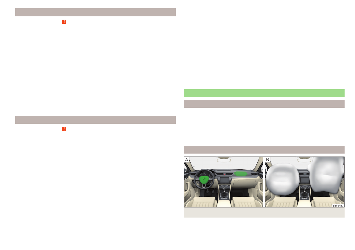
Front airbags
Fig. 8 Locations of the airbags / gas filled airbags
15
Airbag system
15
Page 18
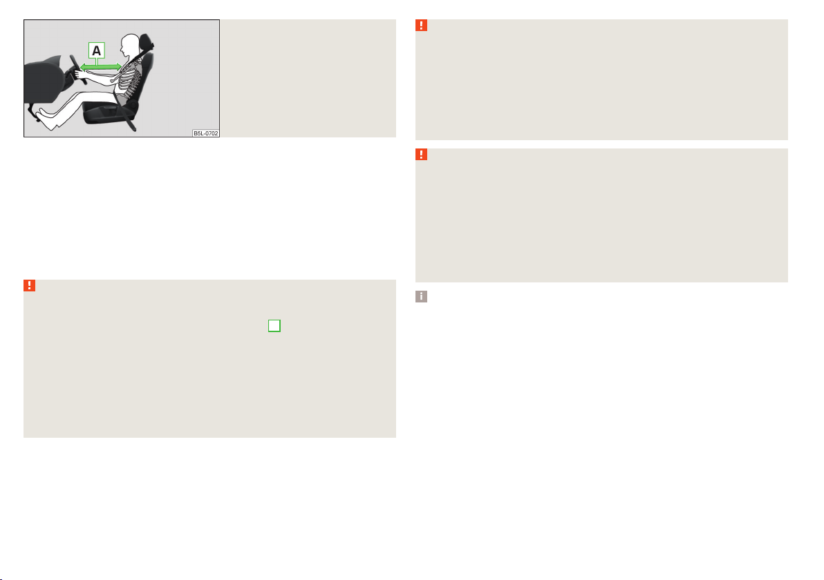
Fig. 9
Safe distance to steering wheel
WARNING
Front airbag and transporting children
■
Never transport children on the front seat of a vehicle without using a
proper restraint system. If airbags are deployed in the event of an accident,
the child might suffer severe or even fatal injuries!
■
The front passenger airbag must be deactivated if using a rear-facing
child seat on the front passenger seat » page 19, Deactivating airbags. If
this is not done, there is a risk of the child suffering severe or even fatal
injuries if the front passenger airbag is deployed.
In the event of a severe frontal collision, the front airbags offer additional protection for the head and chest area of the driver and front passenger.
The driver's front airbag is located in the steering wheel, the front passenger
airbag is located in the instrument panel above the glove compartment » Fig. 8
- .
The airbags inflate in front of the driver and front passenger when they are
deployed » Fig. 8 - . The forward movement of the driver and of the front
passenger is cushioned when they make contact with the fully inflated airbag
and the risk of injury to head and chest is thus reduced.
WARNING
Information on correct seating position
■
It is important that the driver and front passenger maintain a distance of
at least 25 cm to the steering wheel or dashboard A » Fig. 9. Not maintaining this minimum distance will mean that the airbag system will not be able
to properly protect you - hazard! The front seats and the head restraints
must always also be correctly adjusted to match the body size of the occupant.
■
The airbag develops enormous forces when triggered, which can lead to
injuries if the sitting position or seated position is not correct.
■
There must not by any further persons, animals or objects positioned between the front seated occupants and the deployment area of the airbag.
WARNING
General information
■
The steering wheel and the surface of the airbag module in the dash panel on the passenger side must not have stickers attached, be covered or
modified in any other way. These parts should only be cleaned with a cloth
that is dry or has been moistened with water. No objects (such as cup holders, mobile phone mounts, etc.) are to be attached to the covers of the airbag modules or be located within their immediate vicinity.
■
Never place objects on the surface of the front passenger airbag module
in the dash panel.
Note
■
In vehicles with driver's airbag, the text can be found on the steering
wheel.
■
In vehicles with front passenger airbag, the text
is located on the dash
panel on the passenger side.
16
Safety
Page 19

Driver’s knee airbag
Side airbags
Fig. 10 Installation of the airbag / Gas-filled Airbag / Safe distance between the legs and the instrument panel
The driver's knee airbag offers adequate protection for the driver's legs.
The driver's knee airbag
A
is located in the lower part of the dash panel below
the steering column » Fig. 10.
The forward movement of the body is cushioned when it makes contact with
the fully inflated airbag B and the risk of injury to the legs of the driver is thus
reduced.
WARNING
■
Adjust the driver's seat in a forward/back direction so that there is a gap
of at least 10 cm between the legs C and the instrument panel in the vicinity of the knee airbag » Fig. 10. If it is not possible to meet this requirement due to your body size, visit a specialist garage.
■
The surface of the airbag module in the lower part of the dash panel below the steering column not have stickers attached, be covered or modified
in any other way. This part should only be cleaned with a cloth that is dry or
has been moistened with water. Nothing may be attached to the cover of
the airbag module or located within the immediate vicinity.
■
Do not attach any bulky and heavy objects (bunch of keys etc.) to the ignition key. These can be ejected by the knee airbag when it is deployed and
can cause injuries.
Note
In vehicles with a driver's knee airbag, a symbol with is located on the
side panel on the driver's side.
Fig. 11 Installation locations of airbags: the front seat / back
Fig. 12 Inflated airbags
In the event of severe side collisions, the side airbags provide additional protection for the upper body (chest, stomach and pelvis) of passengers in the vehicle.
The front side airbags are housed in the upholstery of the seat backrests of
the front seats » Fig. 11 - .
The rear side airbags are located between the entrance area and the seat
backrest » Fig. 11- .
The load of the occupants is cushioned when plunging into the fully inflated
airbag » Fig. 12 and the risk of injury to the entire upper body (chest, stomach
and pelvis) is reduced on the side facing the door.
Airbag system
17
Page 20
WARNING
Information on correct seating position
■
Your head should never be positioned in the deployment area of the side
airbag. You might suffer severe injuries in the event of an accident. This applies in particular to children who are transported without using a suitable
child safety seat » page 22, Child safety and side airbag.
■
There must not be any further persons, animals or objects positioned between the occupants and the deployment area of the airbag. No accessories, such as cup holders, should be attached to the doors.
■
If children adopt an incorrect seated position when travelling, they may
be exposed to an increased risk of injury in the event of an accident. This
can result in serious injuries » page 20, Child seat.
WARNING
■
Do not place any objects within the deployment area of the side airbags –
risk of injury!
■
The airbag system operates using pressure sensors located in the front
doors. For this reason, no adjustments may be carried out to the doors or
door panels (e.g. installation of additional loudspeakers). Further information » page 192, Airbags.
■
Ensure that there are no excessive forces, such as violent knocks, kicks
etc., impact on the backrests of the seats otherwise the system may be
damaged. The side airbags would not be deployed in such a case!
■
Any seat or protective covers which you fit to the driver or front passenger seats must only be of the type expressly authorized by ŠKODA. In view
of the fact that the airbag inflates out of the backrest of the seat, use of
non-approved seat or protective covers would considerably impair the protective function of the side airbag.
■
Any damage to the original seat covers in the area of the side airbag module must be repaired immediately by a specialist garage.
■
The airbag modules in the front seats must not display any damage,
cracks or deep scratches. It is not permissible to use force in order to open
the modules.
Note
■
In vehicles with side airbags a label with the text is located on the front
seat backrests.
■
In vehicles with rear side airbags, the word AIRBAG is located between the
entrance area and the rear seat rest
.
Head airbags
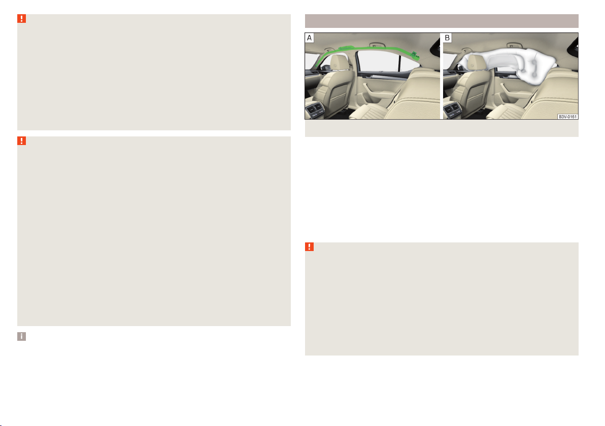
Fig. 13 Location of the head airbag/gas-filled head airbag
In the event of a severe side collision, the head airbags offer additional protection for the head and neck area of passengers.
The head airbags are positioned above the doors on both sides of the vehicle
interior » Fig. 13 - .
When deployed, the airbag covers the window area of the front and rear doors,
as well as the area of the door pillar » Fig. 13 - .
Head impact with interior parts is reduced by the inflated head airbag. The reduction in any impact to the head and the resultant minimizing of any movements of the head additionally reduce the risk of injuries to the neck area.
WARNING
■
There must not be any objects in the deployment area of the head air-
bags which might prevent the airbags from inflating properly.
■
Only hang light items of clothing on the hooks fitted in the vehicle. Never
leave any heavy or sharp-edged objects in the pockets of the items of
clothing. Additionally, clothes hangers must not be used to hang up items
of clothing.
■
The installation of impermissible accessories in the vicinity of the head
airbags can considerably impair the protection offered by the head airbag in
the event of it being deployed. When the deployed head airbag is inflated,
parts of the accessories fitted could, conditions permitting, be thrown into
the interior of the car and injure the occupants » page 190.
18
Safety
Page 21

WARNING (Continued)
■
When objects are attached to the sun visor, the visor can not be pivoted
to the side windows. This might result in injuries to the occupants if the
head airbag is deployed.
■
There must not be any further persons, animals or objects positioned between the occupants and the deployment area of the airbag. In addition,
none of the occupants should lean their head out of the window when driving, or extend their arms and hands out of the window.
Note
In vehicles with head airbags, the lettering can be seen on the B-column
cladding.
Deactivating airbags
Introduction
This chapter contains information on the following subjects:
Deactivating airbags 19
Deactivating the front passenger airbag 19
Deactivating airbags
If you sell your vehicle, provide the complete vehicle documentation to the
new owner. Take care to ensure that the information relating to the possibility
of deactivating the front passenger airbag must be included!
If an airbag in the vehicle is to be turned off, then the buyer is to draw attention to this fact!
Deactivating an airbag should be considered in cases such as the ones below.
▶
If a rear-facing child seat has to be used on the front passenger seat
» page 20, Transporting children safely.
▶
If it is not possible to maintain a distance of at least 25 cm between the middle of the steering wheel and chest, despite the driver's seat being correctly
adjusted.
▶
If special attachments are required in the area of the steering wheel because
of a physical disability.
▶
If different seats have been fitted (e.g. orthopaedic seats without side airbags).
The front passenger airbag can be switched off with the key-operated switch
» Fig. 14 on page 19 - .
We recommend that you ask a ŠKODA service partner to deactivate any other
airbags.
Deactivation indicator
Display of the airbag deactivation » page 35, Safety systems.
Note
A ŠKODA service partner will be able to inform you which, if any, of your vehicle's airbags can or must be deactivated.
Deactivating the front passenger airbag
Fig. 14 Key-operated switch for the front passenger airbag / warning
light for front passenger airbag
Only the front passenger airbag is deactivated with the key switch.
Key switch positions » Fig. 14 -
Passenger front airbag deactivated
Passenger front airbag activated
Switch off
Switch off the ignition.
›
Open the storage box on the front passenger's side.
›
Fold the key bit out completely for the radio key » . With a KESSY key, re-
›
move the emergency key.
Carefully insert the key into the key slot in the key switch as far as the stop.
›
Use the key to turn the slot of the key switch » Fig. 14 carefully into the
›
›
position
Pull the key out of the slot in the key switch » .
.
Airbag system
19
Page 22

Close the storage box on the front passenger's side.
›
Check that the warning light under the text » Fig. 14 -
›
lights up after the ignition is switched on.
Switching on
Switch off the ignition.
›
Open the storage box on the front passenger's side.
›
Fold the key bit out completely for the radio key » . With a KESSY key, re-
›
move the emergency key.
Carefully insert the key into the key slot in the key switch as far as the stop.
›
Use the key to turn the slot of the key switch » Fig. 14 carefully into the
›
position .
Pull the key out of the slot in the key switch » .
›
Close the storage box on the front passenger's side.
›
Check that the warning light under the text
›
lights up after the ignition is switched on.
The warning light goes out 65 seconds after the key switch status has
changed or after the ignition is switched on.
WARNING
■
The driver is responsible for whether the airbag is switched on or switch-
ed off.
■
Only switch off the airbag when the ignition is switched off! Otherwise a
fault can occur in the system for deactivating the airbag.
■
If the warning lights
be deployed in the event of an accident! Have the airbag system checked
by a specialist garage immediately.
■
Do not leave the key inserted in the key-operated switch while driving vibrations can cause the key to turn in the slot and switch on the airbag!
The airbag can be triggered unexpectedly in an accident - it may result in
injury or death!
CAUTION
An insufficiently folded out key bit can damage the key switch!
flash, the front passenger airbag will not
» Fig. 14 -
Transporting children safely
Child seat
Introduction
This chapter contains information on the following subjects:
Use of a child seat on the front passenger seat 21
Use of the child seat in the front passenger seat 22
Child safety and side airbag 22
Classification of child seats 22
Use of child seats fastened with a seat belt 23
To avoid serious injury or death children are always to be in an appropriate
child safety seat with regards to height, weight, and age.
For safety reasons, we recommend that you always transport child seats on
the rear seats.
Child seats complying with the ECE-R 44 Economic Commission for Europe
standard must be used.
Child seats that comply with the ECE-R 44 standard are identified with a test
mark that cannot be removed: a large letter E inside the circle, with the test
number beneath it.
With child safety seats in groups 2 and 3, make sure that the loop-around fittings attached to the child seat headrest is positioned in front of or at the
same height as the loop-around fittings on the B pillar on the passenger side.
WARNING
■
One should never carry children, and also not babies! - on one's lap.
■
Never leave children unattended in the vehicle. Certain outside climatic
conditions can cause life-threatening temperatures in the vehicle.
■
The child must be secured in the vehicle during the entire journey! Otherwise, the child would be thrown through the vehicle in the event of an accident, causing fatal injuries to both the child and other occupants.
20
Safety
Page 23
WARNING (Continued)
■
Children are exposed to an increased risk of injury in the event of an accident if they lean forward or adopt an incorrect seated position when the
vehicle is moving. This particularly applies to children who are transported
on the front passenger seat as they can suffer severe, or even fatal injuries
if the airbag system is deployed!
■
Pay particular attention to the information provided by the manufacturer
of the child safety seat regarding the correct routing of the belt. Seat belts
which are not correctly adjusted can themselves cause injuries even in minor accidents.
■
Safety belts must be checked to ensure that they are running properly.
One should also ensure that the belt is not damaged by sharp-edged fittings.
■
The front passenger airbag must be deactivated if using a rear-facing
child seat on the front passenger seat. Further information » page 21, Use
of a child seat on the front passenger seat.
■
When installing the child seat on the back seat, the corresponding front
seat must be adjusted so that there is no contact between the front seat
and the child seat or the child being transported in a child seat.
■
Before installing a forward-facing child seat with backrest, remove the
headrest » page 87. After removing the child seat, refit the head restraints.
Note
We recommend that you use child seats from ŠKODA Original Accessories.
These child seats were developed and also tested for use in ŠKODA vehicles.
They meet the ECE-R 44 standard.
Use of a child seat on the front passenger seat
Does not apply to Taiwan
Fig. 15
Sticker on the B column on the
front passenger side
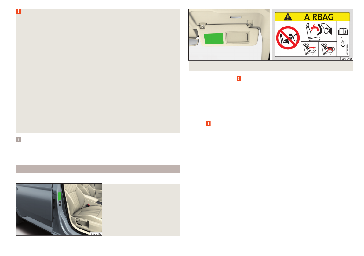
Fig. 16 Front passenger sun visor / label
Read and observe on page 20 first.
Never use a rear-facing child restraint system on a seat which is protected by
an active airbag positioned in front of it. This could cause serious or fatal injury to the child.
The following instructions must be followed when using a child seat on the
front passenger seat.
▶
The front passenger airbag must be deactivated if using a rear-facing child
seat » .
▶
If possible, adjust the front passenger seat backrest so that it is as vertical,
so as to ensure secure contact between the passenger seat backrest and the
back of the child seat.
▶
If possible, move the front passenger seat backwards so that there is no contact between the front passenger seat and the child seat behind it.
▶
Set the height-adjustable front passenger seat as high up as possible.
▶
Set the front passenger seat belt as high up as possible.
▶
When using a child seat where there is a height adjuster in the upper area,
the height of the passenger seat belt is to be set so that the belt is not
“kinked” in the height adjuster. In the event of an accident, there is the risk
of injury to the neck of the child carried due to the seat belt!
Transporting children safely
21
Page 24

WARNING
■
Never use a rear-facing child seat on the front passenger seat if the passenger airbag is activated. This child safety seat is positioned in the deployment area of the front passenger airbag. The airbag may cause the child severe, or even fatal injuries, in the event of it being deployed.
■
This fact is also indicated by the label that can be found in one of the following locations.
■
On the B-column on the front passenger side » Fig. 15. The sticker is
visible upon opening the front passenger door.
■
On the front passenger's sun visor. In some countries, the sticker is lo-
cated on the front seat passenger's sun visor » Fig. 16.
■
As soon as the rear-facing child seat is no longer being used on the passenger seat, the front passenger airbag should be re-activated again.
Use of the child seat in the front passenger seat
Applies to Taiwan
Fig. 17 Front passenger sun visor / label
Read and observe on page 20 first.
No babies, infants or children to be carried on the passenger seat.
Also indicated by the label on the passenger's sun visor » Fig. 17.
Child safety and side airbag
Fig. 18
Incorrect seated position of a
child who is not properly secured
– risk from the side airbag/Child
properly protected by safety seat
Read and observe on page 20 first.
The child must not be positioned in the deployment area of the side airbag
» Fig. 18 - .
There must be sufficient room between the child and the area into which the
side airbag will deploy to allow the airbag to provide as much protection as
possible » Fig. 18 - .
Classification of child seats
Read and observe
Classification of child seats according to the ECE-R 44 standard.
Group Weight of the child
0 up to 10 kg
0+ up to 13 kg
1 9-18 kg
2 15-25 kg
3 22-36 kg
on page 20 first.
22
Safety
Page 25
Use of child seats fastened with a seat belt
Never use a rear-facing child seat on the front passenger seat if the passenger airbag is activated. This child safety seat is positioned in the deployment area of
the front passenger airbag. The airbag may cause the child severe, or even fatal injuries, in the event of it being deployed.
Read and observe on page 20 first.
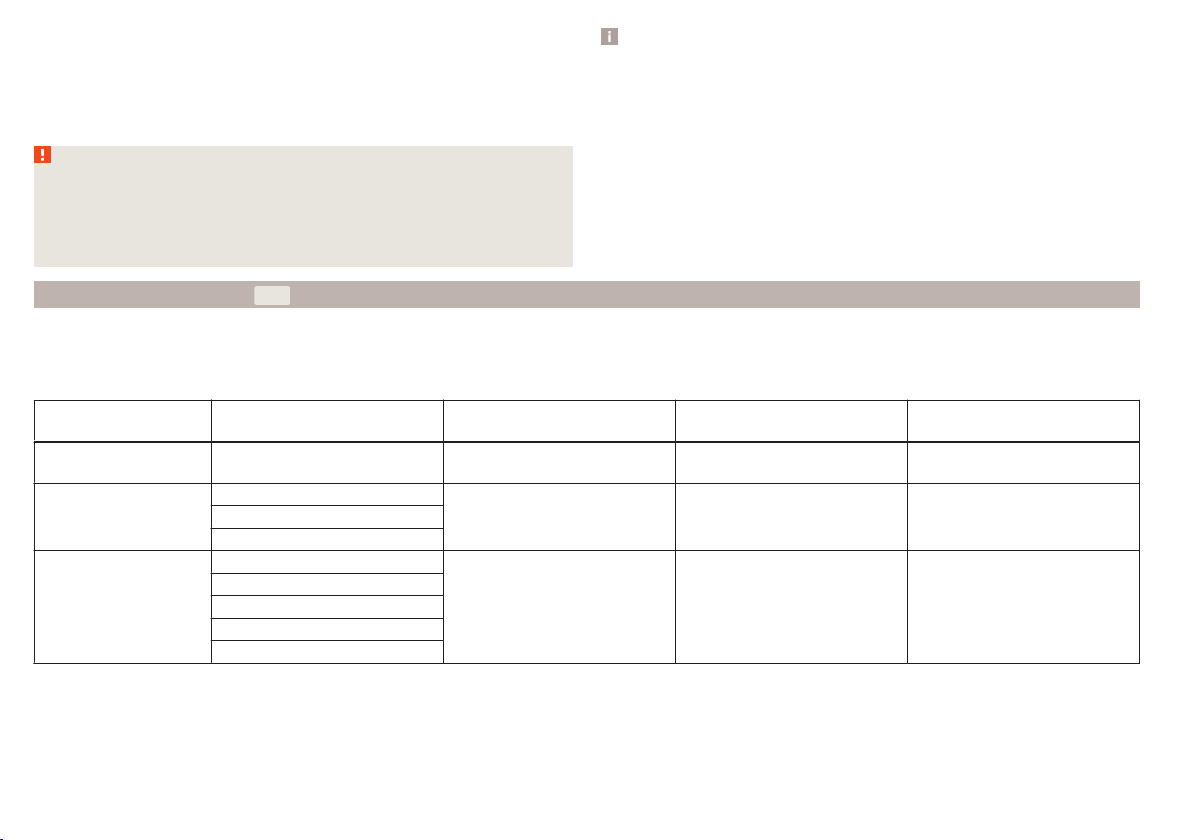
Overview of the usability of child seats secured with a seat belt on seats in accordance with the ECE-R 16 standard.
Group
0
up to 10 kg
0+
up to 13 kg
1
9-18 kg
2
15-25 kg
3
22-36 kg
a)
Set the height-adjustable front passenger seat as high up as possible.
Passenger seat with activated
front airbag
X U
X U
UF U U U
UF U U U
UF U U U
Passenger seat with deactivated
front airbag
a)
a)
Rear seats
External
U U
U U
U The seat is suitable for the use of approved child seats in this weight group category “Universal”.
UF The seat is suitable for the use of approved forward-facing child seats in the “Universal” weight group category.
X The seat is not suitable for children in this weight group.
Fastening systems
attachment points of the system
Introduction
This chapter contains information on the following subjects:
attachment points of the
Use of child seats with the
system
system 24
Use of child safety seats with the
Attachment points of the
- system 25
system 25
23
is a system for securing child seats quickly and safely.
Rear seat
Centre
Fig. 19
Labels of the system
Transporting children safely
23
Page 26
There are two attachment points between the seat backrest and seat cushion
of the outer rear seats and front passenger seat for fixing a child seat with the
system» Fig. 19.
First remove the caps to access the locking eyes.
After removing the child seat, replace he caps.
Note
■
A child seat fitted with the system can only be mounted in a vehicle fitted with a system if the child seat has been approved for this type of vehicle. Further information is available from a ŠKODA Partner.
■
Child seats with the
system can be purchased from ŠKODA Original Ac-
cessories.
WARNING
■
Always refer to the instructions of the manufacturer of the child seat
when installing and removing a child seat with the system.
■
Never attach other child seats, belts or objects to the attachment points
intended for the installation of a child seat with the
system – risk of
death!
Use of child seats with the system
Never use a rear-facing child seat on the front passenger seat if the passenger airbag is activated. This child safety seat is positioned in the deployment area of
the front passenger airbag. The airbag may cause the child severe, or even fatal injuries, in the event of it being deployed.
Overview of the usability of child seats fastened with the system on each of the seats in accordance with the ECE-R 16 standard.
24
Group
0
up to 10 kg
0+
up to 13 kg
1
9-18 kg
Safety
Size class of
the child seat
a)
Front passenger seat
b)
Rear seats outside Rear seat middle
E X IL X
E
X IL XD
C
D
C
B
X
B1
IL
IUF
A
X
Page 27
Group
2
15-25 kg
3
22-36 kg
a)
The size category is shown on the label attached to the child seat.
b)
If the front passenger seat is fitted with system attachment points, it is suitable for the installation of an child seat with “Semi-Universal” approval.
Size class of
the child seat
a)
Front passenger seat
- X IL X
- X IL X
b)
Rear seats outside Rear seat middle
IL The seat is suitable for installation of a child seat with the “Semi-Universal” approval. The “Semi-Universal” category means that the child seat
with the
system is approved for your vehicle. Observe the list of vehicles that comes with the child seat.
IUF The seat is suitable for the use of approved forward-facing child seats in the “Universal” weight group category.
X The seat is not fitted with system attachment points.
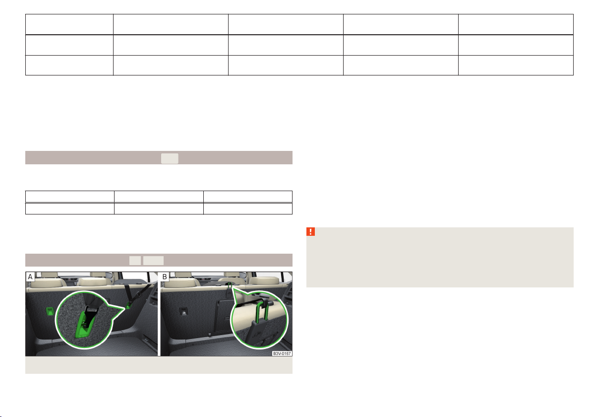
Use of child safety seats with the - system
Overview of the usefulness of child seats fastened with the
each of the seats.
Front passenger seat Rear seats outside Rear seat middle
X i-U X
The seat is suitable for forward and backward facing
i-U
the category “Universal”.
The seat is not suitable for the
X
child seat of the category “Universal”.
system on
child seats of
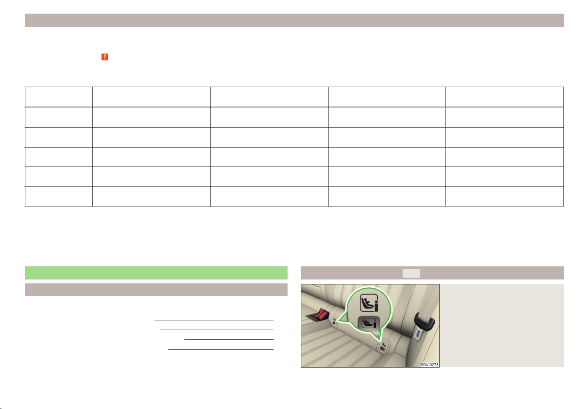
is a fastening system, which restricts the movement of the upper part
of the child seat.
The attachment points for attaching the belt for a child seat with the
system are located on the rear side of the outer rear seat backrests » Fig. 20 -
.
Some country-specific models may also feature an attachment point on the
back of the middle rear seat backrest » Fig. 20 - .
WARNING
■
Always refer to the instructions from the manufacturer of the child seat
when installing and removing a child seat with the system.
Attachment points of the
system
■
Only use child seats with the
system on the seats with the at-
tachment points.
■
Only ever attach one belt from the child seat to a locking eye.
Fig. 20 Attachment points of the
-system
Transporting children safely
25
Page 28
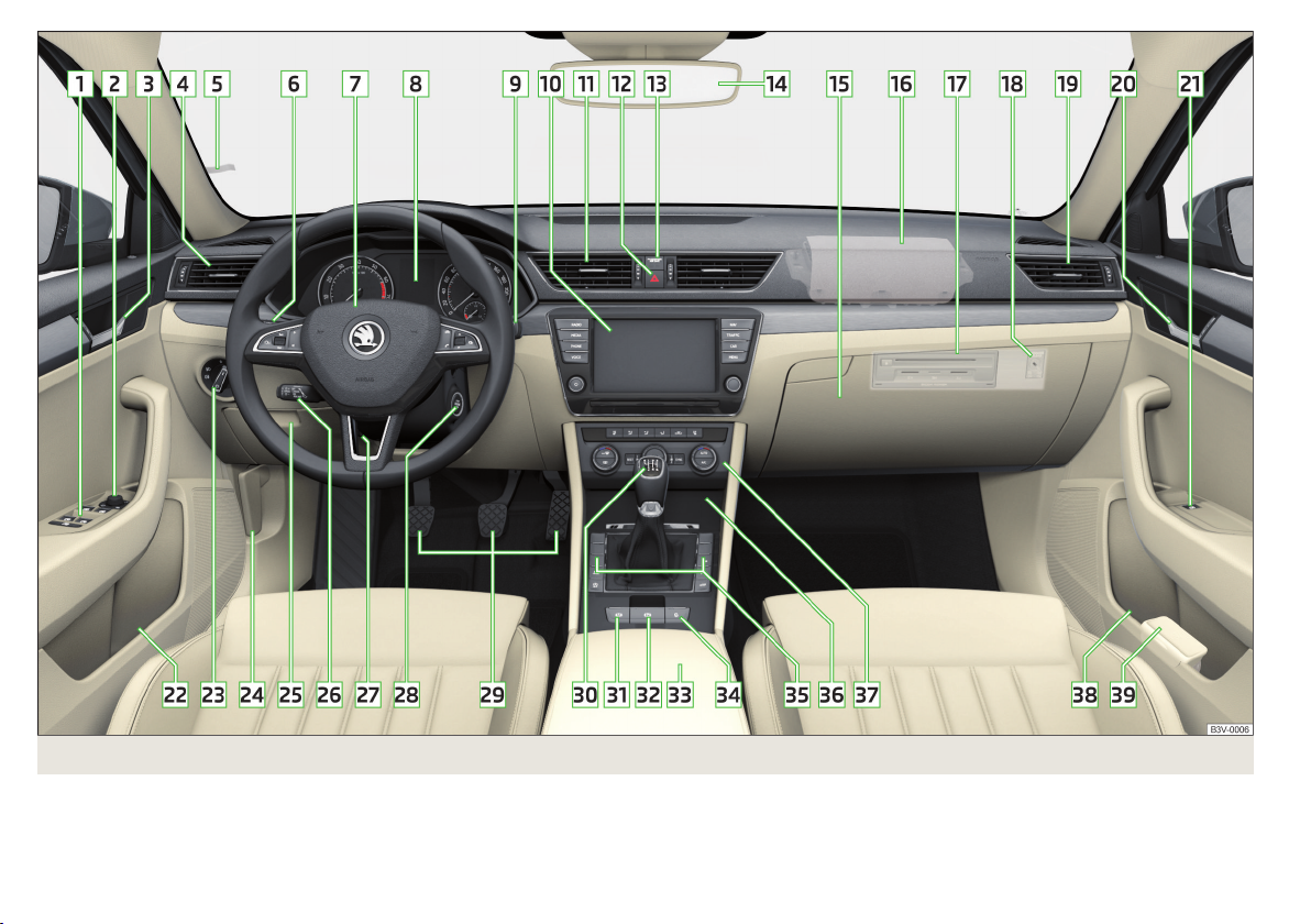
Fig. 21 Cockpit
26
Using the system
Page 29

Using the system
Cockpit
Overview
1
Electric windows 61
2
Electric exterior mirror adjustment 80
3
Door opening lever 56
4
Air outlet nozzle 122
5
Parking ticket holder 91
6
Operating lever (depending on equipment):
▶
Turn signal light, headlight and parking light, headlight
flasher 68
▶
Speed regulating system
▶
Speed limiter
▶
Headlamp assistant
7
Steering wheel (depending on equipment):
▶
With horn
▶
With driver’s front airbag 15
▶
With buttons for the operation of the information system
8
Instrument cluster 28
9
Operating lever:
▶
Windscreen wiper and wash system 77
▶
Information system
10
Infotainment » Owner's Manual for Infotainment
11
Air outlet nozzles
12
Button for hazard warning light system 71
13
Warning light for the front passenger airbag 19
14
Interior rear-view mirror 79
15
Storage compartment on the front passenger side 95
16
Front passenger airbag 15
17
External Infotainment module (in the front passenger storage
compartment) » Owner's Manual Infotainment
18
Key switch for switching off the front passenger airbag (in front
passenger storage compartment) 19
19
Air outlet nozzle 122
20
Door opening lever 56
160
162
72
45
122
21
Power window in the front passenger door 63
22
Storage compartment with bottle storage 91
23
Light switch 67
24
Bonnet release lever 207
25
Storage compartment on the driver's side 91
Fuse box (behind the storage compartment on the driver's
side) 239
26
Operating lever for adaptive cruise control 165
27
Lever for adjusting the steering wheel 9
28
Depending on specification:
▶
Ignition lock 127
▶
Starter button
29
Pedals 135
30
Depending on specification:
▶
Gearshift lever (manual transmission) 135
▶
Selector lever (automatic transmission)
31
Auto-hold button 146
32
Button for the electric parking brake 133
33
Armrest with storage compartment and storage for the tablet 94
34
41
Central locking system 55
35
Bars with buttons depending on the equipment fitted:
▶
START-STOP
▶
Stabilisation control ESC / Traction control TCS 144, 144
▶
Selection of travel mode 171
▶
Park Assist
▶
Parking aid 147
36
Storage compartment 92
Depending on specification:
▶
Phone box 92
▶
12-volt power socket 100
▶
Cigarette lighter 102
▶
Ashtray 103
▶
USB and AUX input » Infotainment Owner's Manual
37
Depending on equipment fitted:
▶
Operating controls for the heating 119
▶
Operating controls for the manual air conditioning system 119
▶
Operating controls for Climatronic 120
128
136
130
155
Cockpit
27
Page 30

38
Storage compartment with bottle storage 91
39
Waste container 93
Note
The arrangement of the controls right-hand drive models may differ from the
layout shown in » Fig. 21. The symbols on the controls and switches are the
same as for left-hand drive models.
Instruments and warning lights
Instrument cluster
Introduction
This chapter contains information on the following subjects:
Overview 29
Revolutions counter 29
Display 29
Coolant temperature gauge 30
Fuel gauge 30
Counter for distance driven 31
Setting the clock 31
Display in rear centre console 31
The instrument cluster gives the driver basic information such as the current
speed, engine speed, the state of some vehicle systems and the like.
If there is a fault in the instrument cluster, the following message will appear
in the display.
Error: instrument cluster. Workshop!
COMBI-INSTRUM_ WORKSHOP
Seek help from a specialist garage.
WARNING
Concentrate fully at all times on your driving! As the driver, you are fully responsible for road safety.
Note
■
If the message
nent protection for the instrument cluster is active. Further information
» page 192, Component protection.
■
With the ignition switched on the instruments are also illuminated. The
brightness of the instrument illumination is set automatically depending on
the ambient lighting throughout.
SAFE CP
appears in the instrument cluster display, the compo-
28
Using the system
Page 31

Overview
The beginning of the tachometer red scale range indicates the maximum permitted speed for an engine that has been driven-in and has reached operating
temperature.
You should shift into the next highest gear before the red scale of the revolution counter is reached, or select mode D on the automatic gearbox.
The gear recommendation is important to note in order to maintain the optimum engine speed » page 42.
CAUTION
The pointer of the tachometer must reach the red area for only a short time there is a risk of engine damage!
Display
Fig. 22 Instrument cluster
Read and observe on page 28 first.
1
Engine rev counter » page 29
▶
with warning lights » page 31
2
Display » page 29
3
Speedometer
▶
with warning lights » page 31
4
Coolant temperature gauge » page 30
5
Bar with warning lights » page 31
6
Button for:
▶
Setting the time » page 31
▶
Reset counter for distance travelled (trip) » page 31
▶
Displaying the distance and days until the next service interval
» page 49
7
Fuel gauge » page 30
Revolutions counter
Read and observe
The tachometer 1 » Fig. 22 on page 29 shows the actual engine speed per
minute.
on page 28 first.
Fig. 23
Display types
Read and observe on page 28 first.
Display types » Fig. 23
MAXI DOT display
Segment display
The following information will be displayed.
▶
Exterior temperature information
▶
Distance travelled » page 31
▶
Time » page 31
▶
Warning lights » page 31
▶
Information system data » page 41
Note
Depending on vehicle equipment, the MAXI DOT display can be either monochromatic “(black and white)” or colour.
Instruments and warning lights
29
Page 32

Coolant temperature gauge
Fuel gauge
Fig. 24
Coolant temperature gauge
Read and observe on page 28 first.
The display » Fig. 24 provides information on the engine coolant temperature.
The display only works if the ignition is switched on.
Cold range
If the pointer is still in the left area of the scale, this indicates that the engine
has not yet reached its operating temperature. Avoid high speeds, full throttle
and high engine loads. This prevents possible damage to the engine.
The operating range
The engine has reached its operating temperature as soon as the pointer
moves into the middle of the scale A » Fig. 24.
High temperature range
If the pointer reaches the red area of the scale, the coolant temperature is too
high.
CAUTION
■
Additional headlights and other attached components in front of the air inlet
impair the cooling efficiency of the coolant.
■
Never cover the radiator - there is a risk of the engine overheating.
Fig. 25
Fuel gauge
Read and observe on page 28 first.
The display » Fig. 25 provides information on the fuel supply in the container.
The display only works if the ignition is switched on.
The fuel tank has a capacity of about 66 litres.
When the fuel level reaches the reserve area A » Fig. 25, the warning light
» page 36 illuminates.
WARNING
For the vehicle systems to function correctly, and thus for safe driving,
there must be sufficient fuel in the tank. Never drain the fuel tank com-
pletely – risk of accident!
CAUTION
Never drive until the fuel tank is completely empty! The irregular supply of fuel
can cause misfiring. This can result in considerable damage to parts of the engine and the exhaust system.
Note
■
After filling up, it can occur that during dynamic driving (e.g. numerous
curves, braking, driving downhill and climbing a steep hill) the fuel gauge indicates approx. a fraction less. When stopping or during less dynamic driving, the
fuel gauge displays the correct fuel level again. This is not a fault.
■
The arrow next to the icon within the fuel gauge displays the installation
location of the fuel filler on the right-hand side of the vehicle.
30
Using the system
Page 33

Counter for distance driven
Fig. 26
Display: MAXI DOT display / Segment Display
Read and observe on page 28 first.
Display » Fig. 26
A
Counter for the distance travelled since the last reset (trip)
B
Odometer
Reset counter for distance travelled (trip)
Press button A » Fig. 27 on page 31.
›
Setting the clock
Fig. 27
Button in the instrument cluster
Read and observe on page 28 first.
Switch-on the ignition.
›
Press and hold the button A » Fig. 27 until the
›
Release the button A and the system switches to the hour setting function.
›
Press the button A again and set the hours.
›
Wait around 4 seconds - the system switches to the minutes setting.
›
Press the button A again and set the minutes.
›
Wait around 4 seconds - the system switches to the start setting.
›
Time
is shown in the display.
The time can also be set in the Infotainment » Owner´s Manual Infotainment,
chapter Device settings.
Display in rear centre console
Fig. 28
Centre console at rear: Display
Read and observe on page 28 first.
The following information is shown in the display depending on the equipment installed on the vehicle.
▶
Time
▶
Exterior temperature information
▶
Information on the Climatronic set temperature for occupants in the rear
seats
Warning lights
Introduction
This chapter contains information on the following subjects:
Parking brake
Brake system 33
Seat belt warning light 33
Automatic Distance Control (ACC) 33
Power steering / steering lock (KESSY system) 33
Stability control (ESC) / Traction control (TCS) 34
Traction control (TCS) deactivated 34
Anti-lock braking system (ABS) 34
Rear fog light 34
Exhaust emissions control system 34
Glow plug system (diesel engine) 34
32
Instruments and warning lights
31
Page 34

Engine electronics check (petrol engine) 35
Safety systems 35
Tyre pressure 35
Brake linings 36
Fuel reserve 36
Lane departure warning (Lane Assist) 36
Turn signal system
Trailer turn signal lights 36
Fog lights 36
Speed regulating system / Speed limiter 37
Brake pedal (automatic transmission) 37
Parking brake - Auto Hold function 37
Main beam 37
Automatic transmission 37
Rear seat belt warning light 37
Alternator 37
Coolant 38
Engine oil pressure too low 38
Engine oil level 38
AdBlue
Lamp failure 39
Diesel particulate filter (diesel engine) 39
Windscreen washer fluid level 40
Headlamp assistant 40
Low temperature displayed 40
Water in the fuel filter (diesel engine) 40
Advance warning / emergency braking (Front Assist) 41
Economy mode 41
Adaptive chassis control (DCC) fault 41
Service 41
®
START-STOP system 40
Automatic Distance Control (ACC) 40
Distance warning (Front Assist) 40
36
39
The warning lights in the instrument cluster indicate certain functions or
faults.
Some warning lights can be accompanied by acoustic signals and messages in
the display of the instrument cluster.
After switching on the ignition, some warning lights light up briefly as a function test.
If the tested systems are OK, the corresponding warning lights go out a few
seconds after switching on the ignition or after starting the engine.
Warning lights in the display
Depending on the importance the warning light (danger) or (warning) illuminate along with some of the warning lights in the list with the warning
lights.
Depending on vehicle specification, some warning lights may be displayed in
colour on the display. For example. the coolant warning lamp may be represented as follows.
▶
- Segment Display / monochromatic (“black and white”) MAXI DOT display
▶
- colour MAXI DOT display
WARNING
■
Ignoring illuminated warning lights and related messages or instructions
in the display of the instrument cluster may lead to serious personal injury
or damage to the vehicle.
■
If you have to stop for technical reasons, then park the vehicle at a safe
distance from the traffic, switch off the engine and switch on the hazard
warning lights » page 71. Place the warning triangle at the prescribed distance.
■
The engine compartment of your car is a hazardous area. The following
warning instructions must be followed at all times when working in the engine compartment » page 206, Engine compartment.
Parking brake
Read and observe
illuminates - the hand brake light is switched on.
Parking brake error
illumi-
Fault: electric parking brake
nates
Seek help from a specialist garage.
Parking on a slope that is too steep
illumi-
Parking brake: grad. too steep. Owner's manual!
nates
on page 32 first.
PARKING BRAKE FAULT
GRADIENT TOO STEEP
32
Using the system
Page 35

Find a parking space on a flat surface or on a slope that is not so steep.
Brake system
Read and observe on page 32 first.
illuminates – the brake fluid level in the braking system is too low.
Brake fluid: Owner's manual!
BRAKE FLUID PLEASE CHECK
Stop the vehicle, switch off the engine, and check the level of the brake fluid
›
» page 212.
WARNING
■
If the warning light illuminates simultaneously with warning light
» page 34, Anti-lock braking system (ABS), do not continue your
journey! Seek help from a specialist garage.
■
A fault to the ABS system or the braking system can increase the vehicle's braking distance – risk of accident!
Seat belt warning light
Read and observe
illuminates - the driver or front passenger has not fastened their seat belt.
At a speed of more than approximately 30 km/h the warning light flashes
and an audible warning sounds at a time.
If the seat belt is not fastened by the driver or front passenger during the next
approx. 2 seconds, the warning signal is deactivated and the warning light
lights up permanently.
Automatic Distance Control (ACC)
Read and observe on page 32 first.
illuminates - ACC deceleration is insufficient.
Apply the brake!
Apply the brake.
›
For more information about the ACC system » page 163.
on page 32 first.
Power steering / steering lock (KESSY system)
Read and observe on page 32 first.
Fault in the power steering
illuminates – this indicates a complete failure of the power steering and the
steering assist has failed (significantly higher steering forces).
illuminates – this indicates a partial failure of the power steering and the
steering forces can be greater.
Seek help from a specialist garage.
Steering lock defect (KESSY system)
An audible signal sounds as a warning.
flashes
Park the vehicle, do not continue to drive. After switching off the ignition, it
is no longer possible to lock the steering, to activate the electrical components
(e.g. Infotainment ), to switch on the ignition again and to start the engine.
Seek help from a specialist garage.
flashes
Seek help from a specialist garage.
Steering column lock not unlocked (System KESSY)
flashes
▶
Move the steering wheel slightly back and forth, thereby facilitating unlocking the steering lock.
If the steering does also not unlock then, the help of a specialist garage is required.
Disconnecting the vehicle battery
If the vehicle's battery has been disconnected and reconnected, the indicator
light comes on after switching on the ignition.
The warning light should go out after driving a short distance.
If, after the motor is restarted and a short drive, the indicator light does not go
out, there is a system error.
Steering lock faulty. Stop!
STOP VEHICLE STEERING FAULTY
Steering lock: Workshop!
STEERING WORKSHOP
Move the steering wheel!
MOVE STEERING WHEEL
Instruments and warning lights
33
Page 36

Seek help from a specialist garage.
Stability control (ESC) / Traction control (TCS)
Read and observe on page 32 first.
flashes – the ESC or TCS is currently active.
ESC or TCS fault
illumi-
nates
or
illumi-
nates
Seek help from a specialist garage.
If the warning light comes on after starting the engine, the TCS may be
switched off for technical reasons.
▶
Switch the ignition off and on again.
If the warning light does not illuminate after you switch the engine back on,
the TCS is fully functional again.
Disconnecting the vehicle battery
If the vehicle's battery has been disconnected and reconnected, the indicator
light comes on after switching on the ignition.
The warning light should go out after driving a short distance.
If, after a short drive, the indicator light does not go out, there is a system er-
ror.
Seek help from a specialist garage.
For more information on the ESC system » page 144 or TCS system
» page 144.
Traction control (TCS) deactivated
Read and observe
illuminates – the TCS system is disabled.
Traction control (ASR) deactivated.
ASR OFF
Error: stabilisation control (ESC)
ESC ERROR
Error: traction control
ASR ERROR
on page 32 first.
Anti-lock braking system (ABS)
Read and observe on page 32 first.
illuminates – there is an ABS fault.
Error: ABS
ABS ERROR
The vehicle will only be braked by the normal brake system without the ABS.
Seek help from a specialist garage.
WARNING
■
If the warning light illuminates simultaneously with warning light
» page 33, Brake system, do not continue your journey! Seek help
from a specialist garage.
■
A fault to the ABS system or the braking system can increase the vehicle's braking distance – risk of accident!
Rear fog light
Read and observe
illuminates – the rear fog light is switched on.
Exhaust emissions control system
Read and observe on page 32 first.
illuminates – there is a fault in the exhaust emissions control system. The
system makes possible operation emergency mode - there may be a noticeable reduction in engine performance.
Seek help from a specialist garage.
on page 32 first.
Glow plug system (diesel engine)
Read and observe
flashes – there is a fault in the engine management system. The system
makes possible operation emergency mode - there may be a noticeable reduction in engine performance.
on page 32 first.
34
Using the system
Page 37

There is a fault in the glow plug system if the warning light does not come
on or illuminates continuously.
Seek help from a specialist garage.
Engine electronics check (petrol engine)
Read and observe on page 32 first.
illuminates – there is a fault in the engine management system. The system
makes possible operation emergency mode - there may be a noticeable reduction in engine performance.
Seek help from a specialist garage.
Safety systems
Read and observe
System fault
illuminates – there is a fault in the airbag system.
Error: Airbag
AIRBAG ERROR
Seek help from a specialist garage.
The front passenger airbag has been disabled with the key switch
Illuminates for around 4 seconds after the ignition has been switched on.
beneath the lettering
panel illuminates after the ignition has been switched on» page 19.
One of the airbags or a belt tensioner has been disabled by the diagnostic
tool
illuminates for approximately 4 seconds after the ignition is switched on
and then flashes for approximately 12 seconds.
Airbag/ belt tensioner deactivated.
AIRBAG/ BELT TENSIONER OFF
ProActive passenger protection
illuminates and one of the following messages is shown in the instrument
cluster display.
Proactive passenger protection not available.
PROACTIVE PASSENGER PROTECT NOT AVAIL
on page 32 first.
in the middle section of the dash
or
Proactive passenger protection: function restricted.
LIMITED PROACTIVE PASSENGER PROTECT
The seat belt for the driver and front passenger needs to be replaced. Seek
help from a specialist garage.
WARNING
When a fault in the airbag system occurs, there is a risk of the system not
being triggered in the event of an accident. Therefore, this must be
checked immediately by a specialized garage.
Tyre pressure
Read and observe
Change of tyre pressure values
illuminates – there was a pressure change in one of the tyres.
An audible signal sounds as a warning.
Immediately reduce speed and avoid sudden steering and braking manoeu-
›
vres.
Stop the vehicle, turn the ignition off and check the tyres and their inflation
›
pressures » page 217.
Correct the tyre pressure if necessary or replace the affected wheel
›
» page 224 or use the repair kit » page 228.
Save the tyre pressure values in the system » page 183.
›
System fault
flashes for approximately 1 minute and remains lit – there may be a fault in
the tyre pressure monitoring system.
Stop the vehicle, turn the ignition off and start the engine again.
›
If the warning light flashes after starting the engine again, there is a system
error.
Seek help from a specialist garage.
Disconnecting the vehicle battery
If the vehicle's battery has been disconnected and reconnected, the indicator
light comes on after switching on the ignition.
The warning light should go out after driving a short distance.
on page 32 first.
Instruments and warning lights
35
Page 38

If, after a short drive, the indicator light does not go out, there is a system error.
Seek help from a specialist garage.
Other incidents
The illumination of the warning light can have the following reasons.
▶
The vehicle is loaded on one side. Distribute loads as evenly as possible.
▶
The wheels of one axle are loaded more heavily (e.g. when towing a trailer or
when driving uphill or downhill).
▶
Snow chains are mounted.
▶
A wheel has been changed.
CAUTION
Under certain circumstances (e.g. sporty style of driving, wintry or unpaved
roads) the warning light can be delayed or does not light up at all.
Brake linings
Read and observe on page 32 first.
illuminates - the brake pads are worn.
Check brake pad!
BRAKE PADS PLEASE CHECK
Seek help from a specialist garage.
Fuel reserve
Read and observe
illuminates – the fuel level in the fuel tank is at the reserve level (approxi-
mately 6 litres).
Please refuel. Range:
PLEASE REFUEL RANGE …
An audible signal sounds as a warning.
Note
The text in the display goes out after refuelling and driving a short distance.
on page 32 first.
Lane departure warning (Lane Assist)
Read and observe on page 32 first.
The warning lights indicates the state of the Lane Assist system.
More information about the Lane Assist System » page 174.
Turn signal system
Read and observe on page 32 first.
flashes – the left turn signal is switched on.
flashes – the right turn signal is switched on.
If there is a fault in the turn signal system, the warning light flashes at twice
its normal rate. This does not apply when towing a trailer.
When the hazard warning light system is switched on, this will cause all of the
turn signal lights as well as both warning lights to flash.
Trailer turn signal lights
Read and observe on page 32 first.
flashes – the trailer turn signal lights are switched on.
If a trailer is hitched and the warning light is not flashing, one of the trailer
turn signal lights has failed.
An example message in the display of the instrument cluster
Trailer: check left turn signal!
TRAILER TURN SIG_ CHECK LEFT
Check the trailer bulbs.
Fog lights
Read and observe on page 32 first.
illuminates – the fog lights are switched on.
36
Using the system
Page 39

Speed regulating system / Speed limiter
Read and observe on page 32 first.
illuminates - the vehicle speed is limited by the speed regulator system
and/or the automatic distance control or by the speed limiter.
flashes – the speed set with the limiter has been exceeded.
Brake pedal (automatic transmission)
Read and observe on page 32 first.
illuminates – apply the brake.
Parking brake - Auto Hold function
Read and observe on page 32 first.
illuminates - the Auto Hold function is activated.
For more information about the Auto-Hold Function » page 146.
Main beam
Read and observe on page 32 first.
illuminates – the main beam or the headlight flasher is switched on.
Automatic transmission
Read and observe on page 32 first.
Gearbox overheated
The warning light is only shown in the MAXI DOTdisplay.
illumi-
nates
illumi-
nates
▶
Do not continue to drive! Stop the vehicle and turn off the engine.
You can continue your journey as soon as the warning light disappears.
Gearbox overheated. Stop! Owner's manual!
STOP VEHICLE GEARBOX OVERHEAT
Gearbox overheated.
GEARBOX OVERHEATED
If the warning light does not go out, do not continue driving. Seek help from a
specialist garage.
Transmission problem
The warning light is only shown in the MAXI DOTdisplay.
illumi-
nates
illumi-
nates
illumi-
nates
Seek help from a specialist garage.
Rear seat belt warning light
Read and observe on page 32 first.
illuminates – a rear seat belt is not fastened.
illuminates – a rear seat belt is fastened.
When the seat belt is fastened/unfastened, the particular light lights up briefly
and indicates the current belt status!
Alternator
Read and observe
illuminates – the battery is not being charged whilst the engine is running.
Seek help from a specialist garage.
CAUTION
If in addition to the light the light lights up while driving, stop driving risk of engine damage! Switch off the engine and seek assistance from a specialist garage.
Gearbox faulty. Workshop!
GEARBOX FAULTY WORKSHOP
Error: gearbox. Reverse gear not available.
GEARBOX ERROR REV_ GEAR NOT AVAIL
Error: gearbox
GEARBOX ERROR
on page 32 first.
Instruments and warning lights
37
Page 40

Coolant
Read and observe on page 32 first.
Coolant level too low
illumi-
nates
▶
Stop the vehicle, switch off the engine and let it cool.
▶
Check the coolant level » page 211, Checking the coolant level.
If the coolant level is within the specified range and the warning light lights
up again, then there may be a malfunction of the cooling fan.
▶
Switch off the ignition.
▶
Check the fuse for the radiator fan, replace if necessary.
If the coolant level and fan fuse are both OK but the warning light lights up
again, stop driving!
Seek help from a specialist garage.
Coolant temperature too high
illumi-
nates
▶
Stop the vehicle, switch off the engine and let it cool.
▶
Continue your journey only after the warning light has disappeared.
Engine oil pressure too low
Read and observe
flashes – the engine oil pressure is too low.
Oil pressure: stop! Owner's manual!
STOP VEHICLE OIL PRESSURE
Stop the vehicle, switch off the engine, and check the engine oil level.
›
Even if the oil level is correct, do not drive any further if the warning light is
flashing. Also do not leave the engine running at an idling speed.
Seek help from a specialist garage.
Check coolant! Owner's manual!
ENGINE COOLANT PLEASE CHECK
Engine overheat. Stop! Owner's manual!
ENGINE OVERHEAT STOP
on page 32 first.
CAUTION
Do not continue if for some reason it is not possible to fill with engine oil un-
der the current circumstances! Switch off the engine and seek assistance
from a specialist garage.
Engine oil level
Read and observe on page 32 first.
Engine oil level too low
illumi-
nates
▶
Stop the vehicle, switch off the engine, and check the engine oil level, top up
if necessary.
The warning light will go out if the bonnet is left open for more than 30 seconds. If no engine oil has been replenished, the warning light will come on
again after driving about 100 km.
Engine oil level too high
illumi-
nates
▶
Stop the vehicle, switch off the engine, and check the engine oil level.
In the event of a high oil level, seek assistance from a specialist garage.
Fault on the engine oil level sensor
illumi-
nates
Seek help from a specialist garage.
CAUTION
Do not continue if for some reason it is not possible to fill with engine oil un-
der the current circumstances! Switch off the engine and seek assistance
from a specialist garage.
Oil level: add oil!
ADD OIL
Reduce oil level!
OIL LEVEL TOO HIGH
Oil sensor: workshop!
OIL SENSOR WORKSHOP
38
Using the system
Page 41

AdBlue
Read and observe on page 32 first.
AdBlue® level too low
Information on the amount of AdBlue®to be added is also shown. The values
"min" and "max" stand for the minimum and maximum AdBlue® replenishment
amounts.
illuminates
The range in the display indicates the distance that can be driven with the remaining AdBlue® left in the tank.
Add AdBlue® » page 204.
illumi-
nates
The value in the display indicates the distance that can still be travelled, after
which no engine restart is possible unless AdBlue® is added.
Add AdBlue® » page 204.
illumi-
nates
It is no longer possible to start the engine.
Add AdBlue® » page 204.
AdBlue® fault
illumi-
nates
There is a fault in the AdBlue® system.
The value in the display indicates the distance to travel, after which no engine
restart is possible.
Seek help from a specialist garage.
illumi-
nates
There is a fault in the AdBlue® system.
It is no longer possible to start the engine.
®
Add AdBlue (DEF)! Range:
ADD ADBLUE (DEF) … RANGE …
Add AdBlue (DEF)! No engine start in ….
ADD ADBLUE (DEF)_NO START IN …
Add AdBlue (DEF)! Engine start disabled.
ADD ADBLUE (DEF) RESTART DISABLED
Error: AdBlue (DEF). No engine start in ….
ADBLUE (DEF) ERROR NO START IN …
Error: AdBlue (DEF). Engine start disabled.
ADD ADBLUE (DEF) RESTART DISABLED
Seek help from a specialist garage.
Lamp failure
Read and observe on page 32 first.
illuminates – one of the lamps is defective. A message will appear con-
cerning the affected lamp.
An example message in the display of the instrument cluster
Check right dipped headlight beam!
DIPPED HEADLIGHT CHECK RIGHT
Diesel particulate filter (diesel engine)
Read and observe
The diesel particulate filter separates the soot particles from the exhaust. The
soot particles collect in the diesel particulate filter where they are burnt on a
regular basis.
illuminates – the filter is clogged with soot.
To clean the filter, and where traffic conditions permit » , drive as follows for
at least 15 minutes or until the indicator light goes out.
4th or 5th gear engaged (automatic gearbox: Position D/S).
Vehicle speed at least 70 km/h.
Engine speed between 1800 - 2500 rpm.
If the filter is properly cleaned, the warning light extinguishes.
If the filter is not properly cleaned, the warning light does not go out and
the warning light begins to flash.
Particulate filter: owner's manual!
PARTICLE FILTER OWNER MANUAL
Seek help from a specialist garage.
on page 32 first.
Instruments and warning lights
39
Page 42

WARNING
■
Always adjust the speed and driving style to the actual weather, road, ter-
rain and traffic conditions.
■
The diesel particulate filter reaches very high temperatures - there is a
fire hazard and serious injury could be caused. Therefore, never stop the
vehicle at places where the underside of your vehicle can come into contact
with flammable materials such as dry grass, undergrowth, leaves, spilled
fuel or such like.
CAUTION
■
As long as the warning light illuminates, one must take into account an
increased fuel consumption and a power reduction of the engine.
■
Using diesel fuel with an increased sulphur content can considerably reduce
the life of the diesel particle filter. A ŠKODA partner will be able to tell you
which countries use diesel fuel with a high sulphur content.
Note
We encourage you to avoid constant short journeys. This will improve the combustion process of the soot particles in the diesel particulate filter.
Windscreen washer fluid level
Read and observe
illuminates – the windscreen washer fluid level is too low.
Add washer fluid!
WASHER FLUID PLEASE TOP UP
Fill up the windscreen washer fluid.
›
on page 32 first.
Headlamp assistant
Read and observe
illuminates – the headlamp assistant is activated » page 72.
START-STOP system
Read and observe on page 32 first.
The warning lights indicates the state of the START STOP system
» page 130.
on page 32 first.
Low temperature displayed
Read and observe on page 32 first.
illuminates – the outside temperature is below +4 °C.
WARNING
Even at temperatures around +4 °C, black ice may still be on the road surface! Do not only rely upon the information given on the outside temperature display that there is no ice on the road.
Water in the fuel filter (diesel engine)
Read and observe on page 32 first.
The fuel filter with water separator, filters out dirt and water from the fuel.
If too much water is present in the separator, the following information ap-
pears on the instrument cluster display.
The warning light is only shown in the MAXI DOTdisplay.
illumi-
nates
Seek help from a specialist garage.
Read and observe on page 32 first.
The warning lights indicate the condition of the ACC system
» page 163.
Water in fuel filter. Owner's manual!
WATER IN FUEL FILTER
Automatic Distance Control (ACC)
Distance warning (Front Assist)
Read and observe
illuminates – vehicle is below the safe distance from the vehicle in front.
The warning light is only shown in the MAXI DOTdisplay.
Information on the Front Assist system» page 168.
on page 32 first.
40
Using the system
Page 43

Advance warning / emergency braking (Front Assist)
Read and observe on page 32 first.
illuminates – the system has detected the risk of a collision or automatically
triggered an emergency braking manoeuvre.
Information on the Front Assist system» page 168.
Economy mode
Read and observe on page 32 first.
illuminates - the vehicle is in economy mode through the intervention of
the active cylinder management or in the neutral position of the automatic
transmission.
Adaptive chassis control (DCC) fault
Read and observe on page 32 first.
The warning light is only shown in the MAXI DOTdisplay.
illumi-
nates
A DCC-fault is present.
Seek help from a specialist garage.
Service
Read and observe on page 32 first.
illuminates – service is due» page 49, Service interval display.
Fault: damper
DAMPER FAULT
Information system
Driver information system
Introduction
This chapter contains information on the following subjects:
Door, luggage compartment or bonnet warning 41
Auto-check control 41
Overspeed warning at 120 km/h 42
Gear recommendation 42
Depending on the vehicle's equipment, the information system vie the display
of the instrument cluster provides the following information.
▶
Driving data (multifunction display) » page 42.
▶
Data relating to the Maxi DOT display » page 45.
▶
Service interval display » page 49.
▶
Selector lever positions for an automatic gearbox » page 136.
▶
Information and alerts in the Assist systems » page 142.
WARNING
Concentrate fully at all times on your driving! As the driver you are fully responsible for the operation of your vehicle.
Door, luggage compartment or bonnet warning
Read and observe on page 41 first.
If at least one door is open, or the boot or bonnet is open, the display indicates
the relevant open door or boot/bonnet.
An acoustic signal will also sound if you drive the vehicle above 6 km/h when a
door is open.
Auto-check control
Read and observe
Certain functions and conditions of individual vehicle systems are checked
continuously when the ignition is switched on.
on page 41 first.
Information system
41
Page 44

While the operational faults remain unrectified, the messages are always indicated again. After they are displayed for the first time, the warning lights
(danger) or (warning) continue to be indicated without information for the
driver.
Overspeed warning at 120 km/h
Read and observe on page 41 first.
This function only applies to certain countries.
An audible warning signal will sound when the vehicle speed exceeds 120
km/h. The audible warning signal is switched off when the vehicle speed falls
below 120 km/h.
Gear recommendation
Fig. 29
Information on the selected
gear / Gear recommendation
Read and observe on page 41 first.
A suitable gear is engaged, if necessary, a recommendation to shift to high or
lower gear is displayed.
A suitably engaged gear helps to reduce the fuel consumption and assist the
service life and reliability of the engine.
Display » Fig. 29
Optimal gear engaged
Recommended gear
Recommended gear
Besides showing the engaged gear, the arrow icon and the recommended
gear are displayed.
For instance, if appears in this display, this means it is recommended that
you shift from 3 rd to 4 th gear .
For vehicles with automatic transmission the recommended gear will be
shown provided the mode for manual switching (Tiptronic) is selected.
WARNING
The driver is always responsible for selecting the correct gear in different
driving situations, such as overtaking.
Driving data (Multifunction display)
Introduction
This chapter contains information on the following subjects:
Operation
Information overview
Warning when exceeding the set speed 44
Memory 44
The driving data display is only possible with the ignition switched on.
After the ignition is switched on, the function that was last selected before
switching off the ignition is displayed.
For vehicles with a MAXI DOT display, the menu item
ted and confirmed in the main menu » page 45, MAXI DOT display.
The setting of the units and the switching on / off the display of some infor-
mation is available possible in the Infotainment » Owner´s Manual Infotain-
ment, chapter CAR - Vehicle Settings.
WARNING
Concentrate fully at all times on your driving! As the driver you are fully responsible for the operation of your vehicle.
Driving data
must be selec-
43
43
42
Using the system
Page 45

Operation
Fig. 30 Buttons / dial: on the control lever / the multifunction steering
wheel
Read and observe
The selection as well as the settings of the data values can be operated with
the buttons on the operating lever as well as on the multi-function steering
wheel » Fig. 30.
Description of the operation
Button /
dial
A
B
C
Briefly press at the top
Turn upwards or down-
on page 42 first.
Action Operation
or down
Press briefly
wards
Press briefly
Select data / set data values
View information / confirm specifica-
Select data / set data values
View information / confirm specifica-
tion
tion
Information overview
Read and observe on page 42 first.
Overview of driving data (depending on the vehicle equipment).
Range
The detail provides information about the distance in km, that can be travelled
with the current tank and with the same driving style.
If you drive more efficiently this value can increase.
AdBlue® range
The detail provides information about the distance in km that can still be travelled with the AdBlue® capacity and with the same driving style.
If you drive more efficiently this value can increase.
Average fuel consumption
The indication is calculated continuously since the last deletion of the memory.
After erasing the memory, no data will appear for the first 100 m driven.
Current fuel consumption
You can use this information to adapt your driving style to the desired fuel
consumption.
When the vehicle is stationary or slowly moving the fuel consumption is displayed in l/h (on models for some countries the following appears --,- km/l).
Oil temperature
If the engine oil temperature is in the range 80-110 °C, the engine operating
temperature is reached.
If the oil temperature is lower than 80 °C or above 110 °C, avoid high engine
revs, full throttle and high engine loads.
If the oil temperature is lower than 50 °C or if there is a fault in the system for
checking the oil temperature
Warning against excessive speeds
Set the speed limit, for example, for the maximum permissible speed in town
» page 44.
Dynamic Road Sign Display
The following road sign will be displayed.
▶
Speed limit.
▶
Overtaking prohibited.
Further information » page 180, Traffic sign recognition.
Current driving speed
The display is identical to the display on the speedometer.
are displayed instead of the oil temperature.
Information system
43
Page 46

Average speed
The indication is calculated continuously since the last deletion of the memory.
After erasing the memory, no data will appear for the first 300 m driven.
Distance travelled
The distance travelled since the memory was last erased is displayed.
The maximum distance indicated is 9,999 km. The indicator is automatically
set back to zero if this period is exceeded.
Driving time
The time travelled since the memory was last erased is displayed.
The maximum distance indicated is 99 hours and 59 minutes. The indicator is
automatically set back to zero if this period is exceeded.
Convenience consumers
There, the total consumption of all consumer comfort in l / h is displayed.
Along with the consumption data, a list of the three consumers with the larg-
est share of fuel consumption (e.g. air conditioning and similar devices) is displayed.
Deactivate speed limit
Select the menu item
›
Confirm the stored value of the speed limits.
›
The speed limit will be disabled.
The speed limit set mode is stored even after the ignition is switched off and
on. After a gap between driving exceeding 2 hours, the pre-set speed limit is
deactivated.
Warning at
at () or () and confirm.
Memory
Fig. 31
Memory display: MAXI DOT display () / Segment display ()
Warning when exceeding the set speed
Read and observe on page 42 first.
The system offers the possibility to set a speed limit beyond which an audible
alarm will sound and the following warning message appears.
Speed ... exceeded.
SPEED TOO HIGH
Adjust the speed limit while the vehicle is stationary
Select the menu item
›
Set the desired speed limit.
›
Confirm the set value, or wait several seconds; your settings will be saved
›
automatically.
The speed limit can be set in 5 km/h intervals.
Adjusting the speed limit while the vehicle is moving
Select the menu item
›
Drive at the desired speed.
›
Confirm the current speed as the speed limit.
›
The set speed limit can be manually adjusted later if needed.
44
Using the system
Warning at
Warning at
at () or () and confirm.
at () or () and confirm.
Read and observe on page 42 first.
Following driving data is stored in three locations.
▶
Average fuel consumption.
▶
Distance driven.
▶
Average speed.
▶
Driving time.
Display of the selected memory in the display at position
Since start
The memory collates the driving information from the moment the ignition is
switched on until it is switched off.
New data will also flow into the calculation of the current driving information if
the trip is continued within 2 hours after switching off the ignition.
If the trip is interrupted for more than 2 hours, the memory is automatically
erased.
( ) Or “1” ( )
A
» Fig. 31.
Page 47

Long-term
( ) And “2” ( )
The memory gathers driving information from any number of individual journeys up to a total of 99 hours and 59 minutes driving or 9,999 kilometres driven.
The indicator is automatically set back to zero if one of the indicated values is
exceeded.
Since refuel
( ) or “3” ( )
The memory gathers driving information since the last refuelling.
The memory is erased automatically the next time you fill up.
Select memory
▶
Select the driving data information desired.
▶
Confirm details again to select the desired memory.
Resetting
▶
Select the driving data information desired.
▶
Select the desired memory.
▶
Reset the selected memory with a long acknowledgement (holding pressed).
Note
Disconnecting the vehicle battery will delete all memory data.
MAXI DOT display
Introduction
This chapter contains information on the following subjects:
Main menu 45
Operation using the operating lever
Operation using the multifunction steering wheel
Menu item
Menu item
Menu item
Menu item
Navigation
Audio
Telephone
Assist systems
Compass point display
Eco-tips
The MAXI DOT display (following as display) is a user interface which, depending on the equipment configuration, delivers information about the Infotainment, the multifunction display, the assistance systems etc.
46
46
47
47
47
48
48
49
WARNING
Concentrate fully at all times on your driving! As the driver you are fully responsible for the operation of your vehicle.
Main menu
Read and observe on page 45 first.
Call up the main menu
Press and hold the button A on the operating lever » Fig. 32 on page 46.
›
or
Press and hold the dial G on the multifunction steering wheel » Fig. 33 on
›
page 46.
Main menu items (depending on vehicle equipment)
■
Driving data
■
Assist systems
■
Navigation
■
Audio
■
Telephone
■
Vehicle
The menus can be opened using the buttons on the control lever » Fig. 32 on
page 46 or on the multi-function steering wheel » Fig. 33 on page 46.
■
If warning messages are displayed, these messages must first be confirmed
to access the main menu.
■
The travel mode can be set in the Infotainment » Owner´s Manual Infotain-
ment, chapter Vehicle settings (SETUP button).
» page 42
» page 48
» page 47
» page 47
» page 47;
» page 41, Auto-check control
Note
Information system
45
Page 48

Operation using the operating lever
Fig. 32
Buttons: on the operating lever
Read and observe on page 45 first.
Description of the operation by means of the buttons on the operating lever
Button Action Operation
Briefly press at the top
A
Press and hold at the top
B
Press briefly Confirm menu item / menu
or down
or down
Switch between menu items / menus
Display main menu
Operation using the multifunction steering wheel
Read and observe on page 45 first.
Description of the operation by means of the buttons on the multi-function
steering wheel
Button /
dial
Action Operation
Voice control on/off / Sound off /on
Press briefly
A
Press and hold button
(applies to vehicles without voice con-
trol)
Activate voice control for
theSmartLinka) function (if supported
by the connected device)
Press briefly
B
Turn up Increase volume
Switch sound on/off / Switch track
playback on/off
Turn down Decrease volume
C
Press briefly
To the next Radio /TV channel or
change to the playback track
Press and hold button Fast forward within the track
D
Press briefly
Switch to the previous radio /TV chan-
nel or to the playback track
b)
Press and hold button Fast reverse within the track
E
Press briefly
Select menu item
» page 48
Take the call / end the call / Menu
F
Press briefly
ephone
display / display call list / call
the selected contact
Assist systems
Tel-
Press and hold button Reject call / Redial last call
Fig. 33 Buttons / dials: on the multifunction steering wheel
46
Using the system
Page 49

Button /
dial
G
H
a)
» Infotainment Owner's Manual
b)
Valid for pressing within about 4 s from the beginning of the given track. Pressing after about 4 seconds
from the beginning of the track, starts the playback from the beginning of the track.
Note
Depending on equipment not all functions may be available. The system indicates this through a text message on the display.
Menu item
Read and observe on page 45 first.
Select menu item
Select and confirm
›
Route guidance takes place
Graphical driving recommendations and other route and destination information are displayed after selection.
No route guidance is carried out
A compass/vehicle symbol is shown to display the current vehicle position in
relation to the compass after selection.
Then turn dial G » Fig. 33 on page 46 on the multifunction steering wheel to
display the
The menu shows the
Last destinations
Action Operation
Press briefly
Turn up
Turn down
Press briefly Return to a previous level in the menu
Press and hold button Display main menu
Confirm menu item / menu / Repeat
the last navigation announcement or
clarify / interrupt traffic report
Previous menu item / trackb) / Show
available list (e.g. list of available
channels, list of the last destinations,
call list)
Next menu item / track / View available list (e.g. List of available channels,
list the last destinations, call list)
Navigation
Navigation
Navigation
in the main menu.
menu.
Home address
menu item and a list of recent destinations.
When you select one of the menu items, the destination name and the following items are displayed.
■
OK
- Start navigation
■
Cancel
- Return to the Navigation menu – the compass/vehicle symbol will be
displayed
If the home address is not defined when the menu item
ted, the following message appears:
ment system.
Menu item
Read and observe on page 45 first.
Select menu item
Select and confirm
›
The following information can be displayed in the display.
■
Radio
■
Currently played station (name/frequency)
■
The selected frequency range (e.g. FM) optionally with the number of the
station button (e.g. FM3), if the station is stored in the memory list
■
List of available station (if more than 5 stations can be received)
■
TP traffic announcements.
■
Media
■
Name of the track being played, if necessary, further information regarding
title (e.g. artist, album name), if this information is stored as a so called ID3
tag on the audio source.
Menu item
Read and observe on page 45 first.
Select menu item
Select and confirm
›
Turn dial G » Fig. 33 on page 46.
›
The system displays a call list.
If the call list includes no entries, the following message appears
able.
Audio
Audio
Audio
Telephone
Telephone
Telephone
in the main menu.
Please enter the home address on the infotain-
in the main menu.
Home address
is selec-
No entries avail-
Information system
47
Page 50

The following symbols are displayed next to each entry in the call list.
Incoming call
Outgoing call
Missed call
Outgoing call
■
Cancel
- Ends the call
Incoming call
■
Answer
– Answer incoming call
■
Reject
– Reject incoming call
■
Ignore
- Mute the ringer (this option is only available if there is no other call)
Ongoing conversation or conference call
■
Hang up
■
■
■
■
■
■
Hands-free
- End a call
Hold
– Hold a call
Continue
– Continue held call
Mic. off
– Microphone off
Mic. on
– Microphone on
Private
– Switch the call to the telephone
– Toggles the call to the device
Ongoing and held call
■
Hang up
■
■
■
■
■
■
Hands-free
Symbols in the display
– End an ongoing call
Call wait.
– Switch to a held call
Conference
Mic. off
Mic. on
Private
– Make a conference call
– Microphone off
– Microphone on
– Switch ongoing call to the telephone
1)
– Switch ongoing call to the device
Charge status of the telephone battery
Signal strength
1)
1)
A telephone is connected to the unit
Missed calls (if there are several missed calls, the number of calls is shown
next to the symbol)
Switch-off microphone
Menu item
Read and observe on page 45 first.
Select menu item
Select and confirm
›
Assist systems
Assist systems
Assist systems
in the main menu.
or
Press the button on the multi-function steering wheel .
›
In the menu
Assist systems
the systems Front Assist, Lane departure warning
(Lane Assist), Rear Traffic Alert and blind spot monitoring can be enabled/disabled.
Compass point display
Fig. 34
Compass display
Read and observe on page 45 first.
Applies to vehicles with factory-installed navigation system.
In the display when the ignition is on, an arrow symbol as well as an abbrevia-
tion for the corresponding direction (in relation to the current direction of travel) are displayed » Fig. 34.
Note
The direction indicator can be displayed at the top or bottom of the screen displayed in response to further information.
1)
This function is only supported by some mobile phones.
48
Using the system
Page 51

Eco-tips
Read and observe on page 45 first.
To minimise fuel consumption, fuel economy tips can appear in the display.
Eco tips are indicated next to the letters ECO-TIP.
For instance, if the air-conditioning is on and a window is open, the following
message appears
Enable/disable » Owner´s Manual Infotainment, chapter CAR - vehicle set-
tings.
ECO TIP Air conditioning switched on: Close windows.
Service interval display
Introduction
This chapter contains information on the following subjects:
Displaying the distance and days until the next service interval
Service messages
Resetting the service interval display
The service interval display shows the time and mileage to the next service
event.
The information regarding the service intervals can be found in the service
schedule.
Displaying the distance and days until the next service interval
Fig. 35
Button in the instrument cluster
Switch-on the ignition.
›
Press and hold the button A » Fig. 35 until the
›
Release the button A.
›
Service
is shown in the display.
In the display the symbol appears for 4 seconds and the following message
for the kilometre or days to the next service appointment.
Oil service … / … Inspection … / …
OIL SERV_ IN … OR … INSPECT_ IN … OR …
The details regarding the remaining kilometres and days to wait until the next
scheduled service can also be displayed in the Infotainment » Owner´s Manual
Infotainment, chapter CAR - vehicle settings.
Service messages
Messages before reaching the scheduled service date
Before the next service date has been reached, the symbol as well as a message about the mileage or days until the next service event appears in the display after switching on the ignition.
Messages upon reaching scheduled service date
Once the service interval is reached, the icon appears in the display after the
ignition is switched on, as well as the following message, for example.
49
49
49
Oil service now!
OIL SERVICE NOW
or
Inspection now!
INSPECTION NOW
or
Oil service and inspection now!
OIL SERVICE + INSP_ NOW
Resetting the service interval display
We recommend that the display reset is completed by a specialist garage.
We recommend that you do not reset the service interval display yourself. Incorrectly setting the service interval display could cause problems to the vehicle.
Variable service interval
For vehicles with variable service intervals, after resetting the oil change service display in a specialist garage, the values of the new service interval are displayed, which are based on the previous operating conditions of the vehicle.
Information system
49
Page 52

These values are then continuously matched according to the actual operating
conditions of the vehicle.
SmartGate
Introduction
Fig. 36
ŠKODA websites
This chapter contains information on the following subjects:
Connection to SmartGate using Wi-Fi 50
Connection to SmartGate using Wi-Fi Direct 51
SmartGate web interface 51
Password/PIN code change 51
SmartGate is a system that transmits certain driving data (such as fuel consumption, speed or similar) via Wi-Fi or Wi-Fi Direct.
The ŠKODA compatible communications device (e.g. phone, tablet, notebook)
offer the possibility to further transmit the received data.
More information on available applications, a list of compatible communication
devices and information about SmartGate can be found on the following
ŠKODA website » Fig. 36.
http://www.skoda-auto.com
WARNING
■
The universally applicable country-specific laws on operating communica-
tion devices in the vehicle must be observed.
■
Never leave a communication device in the deployment area of an airbag,
on a seat, on the dash panel or any another area, from which it could be
thrown during a sudden braking manoeuvre, an accident or a collision - risk
of injury!
■
Never connect or disconnect a communication device while driving - risk
of accident!
CAUTION
■
To increase access security for the vehicle data transmitted, when the
ŠKODA application starts up, there will be a prompt to change the password/PIN code if the default password/PIN code has not yet been changed
» page 51, Password/PIN code change. It is not possible to start the ŠKODA
application without having made this change.
■
ŠKODA accepts no responsibility for any problems caused by incompatibility
or improper functioning of the communication devices.
Note
The ŠKODA applications, support communications devices with the Android
operating system version 4.x.x and later and iOS 7.x.x and higher.
Connection to SmartGate using Wi-Fi
Read and observe
Connecting to an Android communication device
Switch on the ignition.
›
Switch on the Wi-Fi on the communication device to be connected.
›
Start the SmartGate application using the communication device to be con-
›
nected.
Then follow the instructions which are included in the SmartGate application.
›
With SmartGate, a maximum of four communication devices can be connected
simultaneously using Wi-Fi, with as many ŠKODA applications running simultaneously as required.
Connecting to an iOS communication device
Switch on the ignition.
›
and on page 50 first.
50
Using the system
Page 53

Switch on the Wi-Fi on the communication device to be connected.
›
Allow the communication device to be connected to search for available Wi-
›
Fi networks (see the Owner's Manual for the communication device to be
connected).
In the menu of the detected networks select “SmartGate_...”1) or “DIRECT
›
SmartGate_...”1).
Enter the password » page 51.
›
With SmartGate, a maximum of four communication devices can be connected
simultaneously using Wi-Fi. In these communication devices, up to four ŠKODA
applications can be started simultaneously.
Disconnection
Disconnection is possible in one of the following ways.
Switch off the ignition for longer than 5 seconds (for vehicles with a starter
›
button, switch off the engine and open the driver's door).
End the connection in the SmartGate application.
›
Switch off the Wi-Fi on the connected communication device.
›
Automatic connection
If the communication device has already been connected with SmartGate before, then the connection is automatically restored under the following conditions.
The ignition is switched on.
The Wi-Fi on the communication device to be connected is switched on.
The communication device to be connected has stored the password re-
quired for the connection check.
Connection to SmartGate using Wi-Fi Direct
Read and observe
This type of connection is intended for communication devices running the
Android operating system.
Establishing a connection
Switch on the ignition.
›
Start the SmartGate application using the communication device to be con-
›
nected.
Then follow the instructions which are included in the SmartGate application.
›
and on page 50 first.
With SmartGate, a maximum of two communication devices can be connected
simultaneously using Wi-Fi Direct, with as many ŠKODA applications running
simultaneously as required.
If you want to connect to SmartGate in another vehicle, you must first end the
existing connection to the SmartGate application and then re-establish the
connection.
Disconnection
Disconnection is possible in one of the following ways.
Switch off the ignition for longer than 5 seconds (for vehicles with a starter
›
button, switch off the engine and open the driver's door).
End the connection in the SmartGate application.
›
Switch off the Wi-Fi on the connected communication device.
›
Automatic connection
If the communication device has already been connected with SmartGate before, then the connection is automatically restored after the ignition is started.
SmartGate web interface
Read and observe and on page 50 first.
SmartGate parameters can be set in the SmartGate web interface.
The following address must be entered in the web browser of the connected
communication device via Wi-Fi.
HTTP://192.168.123.1
The setting changes are only effective after pressing the “Save” button and
then the “Reboot” button.
Password/PIN code change
Read and observe
The factory set password for the Wi-Fi connection is the complete vehicle
identification number (upper case); the factory set PIN code for the Wi-Fi Direct
connection is the last 6 digits of the vehicle identification number.
and on page 50 first.
1)
The last 6 characters of the vehicle identification number of your vehicle are displayed at position ....
Information system
51
Page 54

After changing the password/PIN, the connection to SmartGate must be re-established on the communication device to be connected using the new password or new PIN code.
If the password/PIN code is still set to the preset factory password/PIN code,
you are requested to change the password/PIN code after starting the ŠKODA
application. Without changing the password/PIN code, you are unable to use
the application.
Changing the password for the Wi-Fi connection
Open the SmartGate web interface.
›
In the menu item “WPA / WPA2 key:” enter the new password (8 to 63 alpha-
›
numeric, special, lower and upper case characters).
Confirm the password change by tapping on the “Save” button.
›
Restart SmartGate by tapping on the “Reboot”1) button.
›
Changing the PIN code for the Wi-Fi Direct connection
Open the SmartGate web interface.
›
In the menu item “WiFi Direct PIN:” Enter the new PIN code (6 digits).
›
Confirm the PIN code change by tapping on the “Save” button.
›
Restart SmartGate by tapping on the “Reboot”1) button.
›
Note
If you have forgotten your password/PIN code for connecting to SmartGate,
SmartGate must be reset to the factory settings in a specialist workshop.
Unlocking and opening
Unlocking and locking
Introduction
This chapter contains information on the following subjects:
Unlocking / locking with the remote control key 53
KESSY override key removal 54
Unlocking / locking - KESSY 54
Locking / unlocking the vehicle with the central locking button 55
Safe securing system 55
Individual settings 56
Opening/closing a door 56
Child safety lock 57
Malfunctions 57
Your car is equipped with a central locking system.
The central locking system allows you to lock and unlock all doors, the fuel fill-
er flap and boot lid at the same time. The functions of the central locking system can be individually adjusted » page 56.
After unlocking, depending on vehicle equipment and setting the following is
valid for the central locking.
▶
The turn signal lights flash twice as confirmation that the vehicle has been
unlocked.
▶
An double audible signal sounds additionally on vehicles which are fitted
with the anti-theft alarm system.
▶
The doors, the boot lid and the fuel filler flap are unlocked.
▶
The interior lamp illuminates.
▶
The SafeLock system is switched off.
▶
The indicator light in the driver door stops flashing.
▶
The exterior mirrors are set into the driving position.
▶
The anti-theft alarm system is deactivated.
1)
If the “Reboot” button is not displayed, you must manually restore the web browser display.
52
Using the system
Page 55

After locking, depending on vehicle equipment and setting the following is
valid for the central locking.
▶
The turn signal lights flash once as confirmation that the vehicle has been
locked.
▶
An audible signal sounds additionally on vehicles which are fitted with the
anti-theft alarm system.
▶
The doors, the boot lid and the fuel filler flap are locked.
▶
The interior lamp goes out.
▶
The SafeLock system is switched on.
▶
The indicator light in the driver door begins flashing.
▶
The exterior mirrors are folded back into the park position.
▶
The anti-theft alarm system is activated.
If the doors or the boot lid remain open after the vehicle has been locked, the
turn signal lights do not flash until they have been closed.
Protection against unwanted vehicle unlocking
If you unlock the vehicle and do not open a door or the boot lid within the next
45 seconds, the vehicle will lock again automatically and the SafeLock system
or anti-theft alarm system will be switched on.
WARNING
■
Never leave the key in the vehicle when you exit the vehicle. Unauthorized persons, such as children, for example, could lock the car, turn on the
ignition or start the engine - there is a danger of injury and accidents!
■
When leaving the vehicle, never leave people who are not completely independent, such as children, unattended in the vehicle. These individuals
might not be able to leave the vehicle on their own or to help themselves.
Can be fatal at very high or very low temperatures!
CAUTION
■
Each key contains electronic components; therefore it must be protected
against moisture and severe shocks.
■
Keep the groove of the keys absolutely clean. Impurities (textile fibres, dust,
etc.) have a negative effect on the functionality of the locking cylinder and ignition lock.
■
If the driver's door has been opened, the vehicle cannot be locked.
Unlocking / locking with the remote control key
Fig. 37 Key: Remote key / KESSY
Read and observe
Function and description of the key » Fig. 37
Unlocking the vehicle
Locking the vehicle
Depending on equipment fitted:
▶
Boot lid unlock/unlatch (vehicles fitted with manual operation)
▶
Luggage compartment door open/close/movement of the luggage compartment door stop (vehicles with electric operation)
A
Button for the extension / retraction of the key
B
Warning light for the battery condition
If the red warning light does not flash when you press a button on the key,
the battery is discharged.
Boot lid unlock/unlatch for vehicles fitted with manual operation
By pressing briefly symbol key the boot lid unlocks.
Press and hold the symbol key to release the lid (partially opened).
If the lid is unlocked or released with the key symbol on the key, then the
lid is automatically locked after closing. You can set a lock delay » page 59.
and on page 53 first.
Unlocking and opening
53
Page 56

CAUTION
■
The operation of the remote control may temporarily be affected by signal interference from transmitters close to the car and which operate in the same
frequency range.
■
The operating range of the remote control key is approx. 30 m. But this range
of the remote control can be reduced if the batteries are weak.
■
The battery must be replaced if the central locking does react to the remote
control at less than around 3 metres away » page 234.
Note
The remote control will operate only when visual contact with the vehicle.
Unlocking / locking - KESSY
KESSY override key removal
Fig. 38 KESSY key
Read and observe and on page 53 first.
Remove retainer tabsA in the direction of arrow 1 » Fig. 38.
›
Remove the emergency key B in the direction of the arrow 2.
›
54
Using the system
Fig. 39 The front door handle
Read and observe
The KESSY system (Keyless Entry Start Exit System) enables unlocking and
locking of the vehicle without actively using the remote control key » Fig. 39.
The sensors for unlocking or locking are located in the handle of the front
door.
Unlocking
Locking
When unlocking or locking the vehicle, the key must be at a maximum distance
of approximately 1.5 m from the front door handle.
Locking
On vehicles fitted with automatic gearbox, the selector lever must be moved
into the position P before unlocking.
The vehicle cannot be locked from the outside if the ignition has not been
turned off.
After locking the car, it is not possible to unlock within the next 2 seconds by
touching the door handle. This can be used to check whether the vehicle is
locked.
Protection against inadvertently locking the key in the vehicle
If one of the doors is closed after the vehicle has been locked and the key with
which the vehicle was locked remains in the passenger compartment, the vehicle will be automatically unlocked. After unlocking the vehicle again, the turn
signal lights will flash four times. If no door is opened within 45 seconds, the
vehicle is automatically locked again.
and on page 53 first.
Page 57

If the boot lid is closed after the vehicle has been locked and the key with
which the vehicle was locked remains in the luggage compartment, the lid will
be unlocked (partially opened). The turn signal lights flash four times as an indication that the boot lid has been unlocked again. The luggage compartment
lid remains released(partially open).
The following message is shown in the instrument cluster display.
Key in vehicle.
KEY IN VEHICLE
CAUTION
■
Some types of gloves can affect the unlocking or locking device in the door
handle.
■
After leaving the car there is no automatic locking.
Locking / unlocking the vehicle with the central locking button
Fig. 40
Central locking button
Read and observe and on page 53 first.
When the vehicle has not been locked from outside and no door is open the
button » Fig. 40 can be used to unlock or lock the vehicle.
The locking is shown by the illuminated symbol .
The central locking system also operates if the ignition is switched off.
The following applies after locking.
▶
Opening the doors and the boot lid from the outside is not possible.
▶
The doors can be unlocked and opened from the inside by a single pull on the
opening lever of the respective door.
WARNING
Doors locked from the inside make it difficult for rescuers to get into the
vehicle in an emergency – risk to life!
Safe securing system
Read and observe and on page 53 first.
As soon as the vehicle is locked from the outside, the safe lock prevents opening the doors from the inside.
This function is pointed out by the following message on the display of the instrument cluster after switching out the ignition.
Check SAFELOCK! Owner's manual!
CHECK SAFELOCK
After locking the vehicle, the warning light in the driver's door flashes for
around 2 seconds in quick succession, afterwards it begins to flash evenly at
longer intervals.
Switching off
The safe lock can be switched off in one of the following ways.
▶
By locking twice within 2 seconds.
▶
By disabling the button for interior monitoring and anti-towing » page 58.
The indicator light in the driver door flashes for about 2 seconds fast, goes out
and starts to flash at longer intervals after about 30 seconds.
If the vehicle is locked and the safe securing system is switched off, the door
can be opened separately from the inside by a single pull on opening lever.
The safelock switches on the next time the vehicle is locked.
WARNING
If the car is locked and the safe securing system activated, no people must
remain in the car as it will then not be possible to either unlock a door or
open a window from the inside. The locked doors make it more difficult for
rescuers to get into the vehicle in an emergency – risk to life!
Unlocking and opening
55
Page 58

Individual settings
Read and observe and on page 53 first.
The following functions of the central locking system can be set individually in
the Infotainment » Owner´s Manual Infotainment, chapter CAR - Car settings.
Opening a single door
The function allows you to unlock only the driver's door and the fuel filler flap
with the radio remote control. KESSY makes possible the release of individual
doors as well as the fuel filler flap, depending on the area in which the key is
located. The other doors and the boot lid are only unlocked when the unlocking is repeated.
Unlocking a vehicle side door
This function enables you to unlock both doors on the driver's side and the
fuel filler flap with the radio remote control unit. KESSY makes possible the release of both doors on one side as well as the fuel filler flap, depending on the
area in which the key is located. The other doors and the boot lid are only unlocked when the unlocking is repeated.
Unlock all doors
The function allows you to unlock all doors, the boot lid and the fuel filler flap.
Automatic locking/unlocking
The function allows you to lock all doors and the boot lid from a speed of
about 15 km / h. The button in the boot lid handle is deactivated.
Renewed automatic unlocking of all doors as well as the luggage compartment
door when removing the ignition key or by opening any of the doors. In vehicles with the system KESSY this is when any door is opened.
The vehicle can also be unlocked by pressing the Central Locking Button in
the centre console » page 55.
Acoustic signals when locking / unlocking
For vehicles with an anti-theft alarm system, the acoustic signals can be enabled / disabled in the Infotainment » Owner´s Manual Infotainment, chapter CAR - Vehicle Settings.
Opening/closing a door
Fig. 41 Door handle/door opening lever
Read and observe
Opening from the outside
Unlock the vehicle.
›
Pull on the door handle A in the direction of the arrow » Fig. 41.
›
Opening from the inside
Pull on door opening lever B of the door and push the door away from you.
›
Closing from the inside
Grasp pull handle C and close the door.
›
WARNING
■
Make sure that the door has closed correctly as it can open suddenly
while driving – risk of death!
■
Only open and close the door when there is no one in the opening/closing
range – risk of injury!
■
An opened door can close automatically if there is a strong wind or the
vehicle is on an incline – risk of injury!
■
Never drive with the doors open - it can be fatal!
and on page 53 first.
56
Using the system
Page 59

Child safety lock
Fig. 42 Rear door: Child safety system switch on / off
Read and observe
and on page 53 first.
The child safety lock prevents the rear door from being opened from the inside. The door can only be opened from the outside.
Switching the child safety lock on/off » Fig. 42
Switching on
Switching off
You can switch the child safety lock on and off using the vehicle key.
Malfunctions
Read and observe and on page 53 first.
Fault with the central locking
If the warning light in the driver's door initially flashes quickly for around 2 seconds, and then lights up for 30 seconds without interruption before flashing
again slowly, you will need to seek the assistance of a specialist garage.
If there is a central locking fault, the key can be used to lock or unlock the driver's door only. The other doors and the boot lid can be manually locked or unlocked.
▶
Locking/unlocking of the Driver's door » page 236.
▶
Locking door » page 236.
▶
Unlocking the boot lid » page 236.
Failure of the system KESSY
If the following message is displayed in the display of the instrument cluster,
then help is required from a specialist company.
Keyless access system faulty.
KEYLESS ACCESS SYSTEM FAULTY
Key battery discharged
If the voltage of the key battery is too low, the following message appears in
the display of the instrument cluster.
Change the key battery!
KEY BATTERY PLEASE CHANGE
Replace the battery » page 234.
Anti-theft alarm system
Introduction
This chapter contains information on the following subjects:
Interior monitor and towing protection
The anti-theft alarm system (hereinafter referred as alarm system) increases
protection against theft and break-in attempts into the vehicle.
The alarm system is activated automatically approximately 30 seconds after
the vehicle is locked. This is automatically disabled after release.
The alarm system triggers audible and visual signals if an attempt is made to
break into the vehicle (hereafter referred to as alarm).
Triggering the alarm
The alarm is triggered when the following unauthorized actions are carried out
on the locked vehicle.
▶
Opening the bonnet.
▶
Opening the boot lid.
▶
Opening the doors.
▶
Manipulation of the ignition lock.
▶
Towing the vehicle.
▶
Movement in the vehicle.
▶
Sudden and significant voltage drop of the electrical system.
▶
Uncoupling the trailer.
If the driver's door of a vehicle is unlocked and opened by the lock cylinder,
then the alarm is triggered.
58
Unlocking and opening
57
Page 60

Switching off the alarm
The alarm is turned off by pressing the button on the key or switching on
the ignition.
CAUTION
Before leaving the vehicle, it must be checked that all of the windows, doors
and the sliding/tilting roof are locked in order to ensure the full functionality of
the anti-theft alarm system.
Note
The alarm system has its own power source. The working life of the power
supply source is 5 years.
Interior monitor and towing protection
Fig. 43
Button for interior monitor and
towing protection
Read and observe on page 58 first.
The interior monitor detects movements inside the locked vehicle and then
triggers the alarm.
The anti-towing detects tilts in the locked vehicle and then triggers the alarm.
Deactivate the interior monitor and the towing protection if there is a possibili-
ty of the alarm being triggered by movements (e.g. by children or animals)
within the vehicle interior or if the vehicle has to be transported (e.g. by train
or ship) or towed.
Deactivate
Switch off the ignition.
›
Open the driver door.
›
Press the symbol key on the B column of the driver's side » Fig. 43.
›
The illumination of the symbol in the button changes from white to orange.
Lock the vehicle within 30 seconds.
›
By disabling the interior monitoring and the anti-towing the safe lock is
switched off.
CAUTION
The opened glasses storage compartment reduces the effectiveness of the interior monitor. To ensure the full functionality of the interior monitor, the
glasses storage compartment must always be closed before locking the vehicle.
Luggage compartment lid
Introduction
This chapter contains information on the following subjects:
Boot lid opening/closing
Delayed locking of the boot lid
When closing the boot lid does do not press on the rear window.
Ensure that the lock is properly engaged after closing the boot lid.
The function of the button in the grip above the licence plate is deactivated
when starting off or at a speed of 5 km/hour or more for vehicles with central
locking. The function is restored after the vehicle stops and the door is
opened.
WARNING
■
Never drive with the boot lid open or ajar, as otherwise exhaust gases
may get into the interior of the vehicle – risk of poisoning!
■
Make sure that when closing the boot lid, no body parts are crushed -
there is danger of injury!
59
59
58
Using the system
Page 61

Boot lid opening/closing
Fig. 44 Opening / closing tailgate
Read and observe
Opening
Press the button A in the direction of arrow 1 » Fig. 44.
›
Raise the lid in the direction of the arrow 2.
›
Closing
Grasp the mount B and lift in the direction of arrow 3.
›
on page 58 first.
Delayed locking of the boot lid
Read and observe on page 58 first.
If the boot lid is unlocked with the symbol key on the key, then the door is
automatically locked after closing.
The period after which the boot lid is locked automatically can be extended by
a specialist garage.
CAUTION
There is a risk of unwanted entry into the vehicle before the boot lid is locked
automatically. We therefore recommend locking the vehicle with the symbol
key on the key.
Electric boot lid
Introduction
This chapter contains information on the following subjects:
Operating description
Set the top position of the lid 60
Malfunctions 61
Boot lid non-contact opening 61
The boot lid (hereinafter as lid) can be operated electrically and manual in the
event of an emergency » page 61.
If the lid hits an obstacle when opening or closing, it stops and an audible signal sounds. When closing the flap is lifted additionally.
WARNING
■
Ensure that the lock is properly engaged after closing the lid. Otherwise,
the lid might open suddenly while the vehicle is moving, even if the lid was
locked – risk of accident!
■
Never drive with the lid open or unlatched, as otherwise exhaust gases
may get into the interior of the vehicle – risk of poisoning!
■
Only open and close the lid when no one is in the opening/closing range –
risk of injury!
■
Make sure that no limbs are caught or crushed when closing the lid - risk
of injury!
CAUTION
Do not attempt to close the door manually during electrical closing process there is a risk of damaging the system of an electric valve operation.
CAUTION
■
Before opening or closing the lid, check if there are any objects in the open-
ing or closing range which could obstruct the movement (e.g. a load on the
roof rack or on the trailer, etc.) – risk of causing damage to the lid!
■
In certain circumstances, if the lid is loaded (e.g. by a thick layer of snow), the
opening process of the lid can be interrupted. Remove the snow from the lid to
re-enable the electrical operation.
■
If the lid closes automatically (e.g. under load of snow), you will hear an inter-
mittent beep.
■
The flap is always to be close before disconnecting the battery.
60
Unlocking and opening
59
Page 62

Operating description
Fig. 45 Lid operation
Fig. 46 Button for the lid operation / button on the key
Read and observe and on page 59 first.
Open flap
The lid can be opened in one of the following ways.
▶
By pressing the handle A » Fig. 45.
▶
By pressing the button C » Fig. 46.
▶
By pressing the symbol key on the key (for approx. 1 s).
Close the flap
The lid can be closed in one of the following ways.
▶
By pressing the button B » Fig. 45.
▶
By pressing the symbol key on the key (for approx. 1 s). Applies to vehicles
with KESSY. The key must be at a maximum distance of about 2 m from the
door.
▶
By pressing the handle A » Fig. 45.
▶
By briefly pressing the door in the closing direction.
Stop lid movement
The lid movement can be stopped in one of the following ways.
▶
By pressing the button B » Fig. 45.
▶
By pressing the button C » Fig. 46.
▶
By pressing the symbol key on the key (for approx. 1 s).
▶
By pressing the handle A » Fig. 45.
Audible signals
Audible beeps in the following cases.
▶
Opening the lid by pressing the symbol button on the key.
▶
Closing the lid by pressing the symbol button on the key (applies to vehicles with KESSY).
▶
Opening the lid by means of button C » Fig. 46,
Note
If you rapidly enter the vehicle during the opening or closing process of the lid,
the whole vehicle may jerk and as a result the movement of the lid can be interrupted.
Set the top position of the lid
Read and observe and on page 59 first.
If the space for opening the lid is restricted (e.g. height of garage) or for more
convenient operation (e.g. according to a person's height), it is possible to adjust the top position of the boot lid.
Adjusting
Stop the lid in the desired position (electrically or manually).
›
Press and hold the button B » Fig. 45 on page 60 for longer than 3 seconds.
›
The setting of the lid top position is confirmed by an acoustic signal.
Delete
Carefully raise the flap manually to the limit.
›
Press and hold the button B » Fig. 45 on page 60 for longer than 3 seconds.
›
An audible signal is emitted. The original position is deleted and the top lid position is set.
60
Using the system
Page 63

Note
The top position which is reached when the lid opens automatically, is always
lower than the maximum top position which can be reached when the lid is
opened manually.
Malfunctions
Read and observe and on page 59 first.
Examples of operational malfunctions
Description of the malfunction
The lid cannot be opened Unlocking the lid » page 236
The lid does not react to an
opening signal
The lid remains in the top
position
The lid is open and the battery was disconnected
Close manually
Close the door slowly and completely. It must be ensured that when pressing
the lid into the lock, pressure is applied to the centre edge of the lid above the
ŠKODA logo.
Remedy
Removing a possible obstacle (e.g. snow), reopening the lid » page 60
Pressing handle A » Fig. 45 on page 60 and
pulling the lid upwards
Manual closing of the lid
Boot lid non-contact opening
Fig. 47
Opening the boot lid
Read and observe and on page 59 first.
Depending on equipment the boot lid can be opened without contact.
Opening
The ignition must be switched off.
Stand with the vehicle key centred on the rear bumper.
›
Ensure that no one is standing within the opening range of the lid.
›
Move one foot in the sensor area below the rear bumper quickly in the direc-
›
tion of the arrow » Fig. 47.
The stop lamp in the rear lid illuminates and the lid opens automatically.
If the lid does not open, then repeat opening after a few seconds.
The function can be enabled/disabled in the Infotainment » Owner´s Manual
Infotainment, chapter CAR - vehicle settings.
We recommend that the function is deactivated in the following cases
▶
Installation of a roof rack.
▶
Coupling a trailer.
▶
Manual vehicle wash.
▶
Maintenance and repairs in the opening area of the boot lid.
When connecting a device to the trailer socket the deactivation of the function
takes place.
WARNING
When you open the boot lid make sure that there are no persons in the
opening area of the lid - there is a danger of injury!
Note
With heavy rain or dirty rear bumper it may occur under certain circumstances
that there may be limitations, or the automatic deactivation of the non contact
opening function of the boot lid may occur.
Window operation
Introduction
This chapter contains information on the following subjects:
Opening/closing the windows
Open / close the window in the passenger door and the rear doors 63
Unlocking and opening
62
61
Page 64

Force limit 63
Window comfort operation 63
Malfunctions 64
The windows in the doors can be operated electrically by means of the buttons
contained in the doors.
WARNING
The system is fitted with a force limiter » page 63. If there is an obstacle,
the closing process is stopped and the window goes down by several centimetres. However, the windows should be closed carefully – risk of injury.
Opening/closing the windows
Fig. 48
Buttons for window lifter
CAUTION
■
If windows are frozen, always remove ice » page 196, Windows and external
mirrors before operating the electrical power windows. The window seals and
the electrical power window mechanism can otherwise be damaged.
■
In the winter, ice accumulating on the surface of the window may cause
there to be more resistance when closing the window. The window will stop
and move back several centimetres. It is necessary to deactivate the force limiter to close the window » page 63.
■
Always make sure that the windows are closed when you leave the locked
vehicle.
■
Keep the windows clean to ensure the correct functionality of the electric
windows.
■
Always close the windows before disconnecting the battery.
For the sake of the environment
At high speeds you should keep the windows closed to prevent unnecessarily
high fuel consumption.
Note
When driving always use the existing heating, air conditioning and ventilation
system for ventilating the interior of the vehicle. If the windows are opened,
dust and other dirt can get into the vehicle and the wind noise is more at certain speeds.
62
Using the system
Read and observe and on page 62 first.
All windows can be operated from the driver's seat.
Power window buttons » Fig. 48
A
Front door left
B
Front door right
C
Rear door, left
D
Rear door, right
E
Disable / enable the buttons in the rear doors
Opening
Lightly press the appropriate button down and hold it until the window has
›
moved into the desired position.
Releasing the button causes the window to halt immediately.
The window can be completely opened automatically by briefly pressing the
button as far as the stop. Renewed pressing of the button causes the window
to stop immediately.
Closing
Pull gently on the top edge of the corresponding button and hold until the
›
window has moved into the desired position.
Releasing the button causes the window to halt immediately.
The window can also be fully closed automatically by pulling the button up to
the stop. Renewed pulling of the button causes the window to stop immediately.
Disable / enable buttons in the rear doors
Press the button E » Fig. 48.
›
Page 65

When the buttons are disabled in the rear doors, the warning light in the
button E lights up.
After switching the ignition off, it is still possible to open or close the windows
for approx. 10 minutes.
After the driver's or passenger's door is opened the operation of the window is
only possible with the button A» Fig. 48, in which case they have to be press-
ed or pulled for approx. 2 seconds.
The window lift mechanism is equipped with protection against overheating.
Repeated opening and closing of the window can cause this mechanism to
overheat. If this happens, it will not be possible to operate the window for a
short time. You will be able to operate the window again as soon as the overheating protection has cooled down.
WARNING
If the rear seats are accommodating people who are not completely independent, e.g. children, it is recommended that for safety reasons the buttons in the rear doors are disabled with the button E .
Open / close the window in the passenger door and the rear doors
Fig. 49
Power window button
Read and observe and on page 62 first.
There is a button in the front passenger door and in the rear doors for that
window.
Opening
Lightly press the button down and hold it until the window has moved into
›
the desired position.
Releasing the button causes the window to halt immediately.
The window can be completely opened automatically by briefly pressing the
button as far as the stop. Renewed pressing of the button causes the window
to stop immediately.
Closing
Pull gently on the top edge of the button and hold until the window has
›
moved into the desired position.
Releasing the button causes the window to halt immediately.
The window can also be fully closed automatically by pulling the button up to
the stop. Renewed pulling of the button causes the window to stop immediately.
Force limit
Read and observe and on page 62 first.
The electrical power window system is fitted with a force limiter.
If there is an obstacle, the closing process is stopped and the window goes
down by several centimetres.
If the obstacle prevents the window from being closed during the next 10 sec-
onds, the closing process is interrupted once again and the window goes down
by several centimetres.
If you attempt to close the window again within 10 seconds of the window being moved down for the second time, even though the obstacle was not yet
been removed, the closing process is only stopped. During this time it is not
possible to automatically close the window. The force limiter is still switched
on.
The force limiter is only switched off if you attempt to close the window again
within the next 10 seconds - the window will now close with full force!
If you wait longer than 10 seconds, the force limiter is switched on again.
Window comfort operation
Read and observe
The convenience operation of the windows offers the possibility of opening or
closing all the windows at once.
Settings the window convenience operation » Infotainment Owner's Manual,
chapter Vehicle settings (button CAR).
and on page 62 first.
Unlocking and opening
63
Page 66

Convenience operation can take place in one of the following ways.
Opening
Press and hold the symbol key on the key.
›
Switch off the ignition, open the driver's door and hold the key A until it
›
stops in the open position » Fig. 48 on page 62.
Closing
Press and hold the symbol key on the key.
›
Switch off the ignition, open the driver's door and hold the key A until it
›
stops in the closed position » Fig. 48 on page 62.
In the KESSY system, hold your finger on the sensor on the outside of the
›
door handle of the front door » Fig. 39 on page 54.
The prerequisite for ensuring that the convenience operating feature correctly
is the automatic opening/closing of all windows is operational.
Convenience opening or closing the window using the key in the driver's door
locking cylinder is only possible within 45 seconds of locking the vehicle.
The movement of the window is stopped immediately when the respective
button is released.
Malfunctions
Read and observe and on page 62 first.
If the battery has been disconnected and reconnected, it is possible that the
automatic window lifter will not operate. The system must be activated.
Activation sequence
Switch-on the ignition.
›
Pull the top edge of the button and close the window.
›
Release the button.
›
Pull the relevant button upwards again for approx. 1 second, and keep it
›
pressed down.
Panorama sliding/tilting roof
Introduction
This chapter contains information on the following subjects:
Operation 64
Power limit
65
Convenience operation of sliding / tilting roof 65
Sliding / tilting roof malfunction 65
Manual operation of sunblind 66
Electrical operation of the sunblind 66
Malfunction of the sun blind 66
The panoramic sliding/tilting roof (abbreviated in the following as 'sliding/tilting roof') can only be operated when the ignition is turned on and when the
outdoor temperature is higher than -20 °C.
The sliding/tilting roof can still be operated for approx. 10 minutes after
switching the ignition off. However, as soon as the driver or front passenger's
door is opened it is no longer possible to operate the sliding/tilting roof.
CAUTION
Always close the sliding/tilting roof before disconnecting the battery.
Operation
Operation of the sliding/tilting roof
Fig. 50
Read and observe on page 64 first.
Operation of the sliding/tilting roof » Fig. 50
1
Gradual opening
2
Complete opening
3
Gradual closing
4
Complete closing
5
Gradual opening (sliding)
6
Complete opening (sliding)
64
Using the system
Page 67

7
Gradual closing
8
Complete closing
WARNING
When operating the sliding/tilting roof, proceed with caution to avoid causing crushing injuries – risk of injury!
CAUTION
During the winter it may be necessary to remove any ice and snow in the vicinity of the sliding/tilting roof before opening it to prevent any damage to the
opening mechanism.
Power limit
Read and observe on page 64 first.
The sliding/tilting roof is fitted with a force limiter.
If there is an obstacle, the closing process is stopped and the window goes
down by several centimetres.
The closing of the sliding/tilting roof without power limitation is only with the
third attempt at closing. The time interval between the individual closing attempts should not exceed 5 s - the sliding/tilting roof closes with full force!
Convenience operation of sliding / tilting roof
Read and observe on page 64 first.
The comfort controls makes it possible to open or close the sliding/tilting roof
using the key or the KESSY system above the sensor in the door handle of the
front door.
Tilting roof
The sliding/tilting roof can be opened as follows.
Press and hold the symbol key on the key.
›
Closing
The sliding/tilting roof can be closed as follows.
Press and hold the symbol key on the key.
›
In the KESSY system, hold your finger on the sensor on the outside of the
›
door handle of the front door » Fig. 39 on page 54.
By interrupting the locking process, the closing operation is interrupted.
WARNING
Close the sliding/tilting roof carefully – risk of injury!
Sliding / tilting roof malfunction
Fig. 51
Operation of the sliding/tilting
roof
Read and observe on page 64 first.
If the battery has been disconnected and reconnected, it is possible that the
sliding/tilting roof will not operate. The sun roof must be activated.
Activation sequence
Switch-on the ignition.
›
Pull the switch on the recess in the direction of arrow 1 » Fig. 51 all the way
›
down and hold.
The sliding/tilting roof opens and closes again after around 10 seconds.
Release the lever.
›
Unlocking and opening
65
Page 68

Manual operation of sunblind
Fig. 52
Operation of the sun blind
By briefly pressing the button, the sun blind is fully opened or closed. The
movement of the sun blind can be stopped by briefly pressing any button.
By pressing and holding down the button the sun blind is opened or closed in
the desired position. By releasing the button, the opening or closing process is
stopped.
WARNING
When operating the sun blind, proceed with caution to avoid causing crushing injuries – risk of injury!
Read and observe on page 64 first.
The Sun blind of the sliding/tilting roof is opened manually by pulling up on the
handle in the direction of the arrow A and closed in the direction of the arrow
B
» Fig. 52.
WARNING
When operating the sun blind, proceed with caution to avoid causing crushing injuries – risk of injury!
Electrical operation of the sunblind
Fig. 53
Operation of the sun blind
Read and observe on page 64 first.
The sliding sun blind (hereinafter referred to as sun screen) can be opened or
closed using the buttons.
Operation of the sun blind » Fig. 53
Opening
Closing
66
Using the system
Malfunction of the sun blind
Read and observe on page 64 first.
If the battery has been disconnected and reconnected, it is possible that the
sun blind will not operate correctly. The sun blind must be activated.
Activation sequence
Switch on the ignition.
›
Press the button and hold down.
›
The sun screen opens and closes again after around 10 seconds.
Release the button.
›
Page 69

Lights and visibility
Lights
Introduction
This chapter contains information on the following subjects:
Operating the lights 67
Daylight running lights (DAY LIGHT) 68
Turn signal and main beam 68
Automatic driving lamp control 69
Xenon headlight 69
Front and rear fog lights 70
Fog lights with the CORNER function 71
COMING HOME / LEAVING HOME 71
Hazard warning light system 71
Parking lights 72
Driving abroad 72
Unless otherwise stated, the lights only work when the ignition is switched on.
The arrangement of the controls right-hand drive models may differ from the
layout shown in » Fig. 54 on page 67. The symbols which mark the positions
of the controls are identical.
Keep the headlights lenses clean » page 197, Headlight glasses.
WARNING
The automatic driving lamp control only operates as a support and
does not release the driver from his responsibility to check the lights and, if
necessary, to switch on the light depending on the prevailing light conditions.
Note
■
The headlights may mist up temporarily. When the driving lights are switched
on, the light outlet surfaces are free from mist after a short period, although
the headlight lenses may still be misted up in the peripheral areas. This mist
has no influence on the life of the lighting system.
■
If the visibility is poor and the lights are not on (except daytime running light)
the brightness of the instrument lighting reduces to alert the driver to switch
on the lights in due time.
■
The brightness of the instrument lighting with the lights on (except daytime
running lights) can be set in the Infotainment » Owner´s Manual Infotainment,
chapter CAR - Vehicle Settings.
Operating the lights
Fig. 54
Light switch and control dial for
the headlight beam range regulation
Read and observe on page 67 first.
Switching lights on and off
Depending on the equipment configuration, the light switch A» Fig. 54 can be
turned to one of the following positions.
Switching off lights (except daytime running lights)
Switching lights on/off automatically » page 69
Switching on the side light or parking light » page 72
Switching on the low beam
Headlight range control
Turn the dial B » Fig. 54 from position to to gradually adjust the headlight
range control and shorten the light cone.
The positions of the width of illumination correspond approximately to the following car load.
Front seats occupied, boot empty
All seats occupied, boot empty
Lights and visibility
67
Page 70

All seats occupied, boot loaded
Driver seat occupied, boot loaded
Xenon headlight
The Xenon bulbs adapt automatically to the load and driving state of the vehicle when the ignition is switched on and when driving. Vehicles that are equipped with Xenon headlights do not have a manual headlight range adjustment
control.
WARNING
Always adjust the headlight range control to meet the following conditions.
■
The vehicle does not dazzle other road users, especially oncoming vehi-
cles.
■
The beam range is sufficient for safe driving.
Note
■
The light switch is in position or and the ignition is turned off, the low
beam is switched off automatically 1) and the status light is lit. The side light is
switched off when the ignition key is removed, for vehicles with the KESSY
system after switching off the ignition and opening the driver's door.
■
If there is a fault in the light switch, the low beam comes on automatically.
Daylight running lights (DAY LIGHT)
Read and observe on page 67 first.
The daytime running lights light up the area in front of and to the rear of the
vehicle (only applicable for some countries).
The lights are switched on automatically if the following conditions are met.
The light switch is in the position or
The ignition is switched on.
WARNING
Always switch on the low beam when visibility is poor.
.
Turn signal and main beam
Fig. 55
Operating lever: Turn signal and
main beam operation
Read and observe on page 67 first.
Operating lever positions » Fig. 55
A
Activate right turn signal light - indicator light flashes in the instrument
cluster
B
Activate left turn signal light - indicator light flashes in the instrument
cluster
C
Depending on equipment (spring-tensioned position):
▶
Switch on main beam – indicator light lights up in the instrument cluster
▶
Activate headlamp assistant » page 72
D
Depending on equipment (spring-tensioned position):
▶
Switch off main beam / headlight flasher on (spring-tensioned position)
▶
Deactivate headlamp assistant / activate headlight flasher (spring-tensioned position)
The main beam can only be switched on when the low beam lights are on.
The headlight flasher can be operated even if the ignition is switched off.
The turn signal light switches itself off automatically when driving around a
curve or after making a turn.
“Convenience turn signal”
When the control lever is lightly pressed to the pressure point
the respective turn-signal lamp flashes three times.
A
or B then
1)
Does not apply to the position , as long as the conditions are met for the COMING HOME function
» page 71.
68
Using the system
Page 71

If during the “comfort flashing” the operating lever in the opposite side is
pressed, then the blinking stops.
The “Lane change flash” can be activated/deactivated in the Infotainment
» Owner´s Manual Infotainment, chapter CAR - vehicle settings.
WARNING
Only turn on the main beam or the headlight flasher if other road users will
not be dazzled.
Automatic driving lamp control
Fig. 56
Light switch: AUTO position
Read and observe on page 67 first.
The light switch is in position
the automatic switch on / off the lights corresponding to the light or weather
conditions (rain) takes place.
The sensitivity of the sensor for the determination of the ambient light can be
adjusted in the infotainment » Owner´s Manual Infotainment, chapter CAR -
vehicle settings.
If the light switch is in position
light switch. If the light is switched on automatically, the symbol next to the
light switch also lights up.
Automatic driving light control during rain
The dipped beam is switched on automatically if the following conditions are
met.
The function is activated.
The light switch is in the position
The windscreen wipers are on for more than 30 s.
The light turns off about 4 minutes after turning off the wipers.
» Fig. 56 then depending on the equipment
, the lettering
illuminates next to the
.
Automatic headlight control in rain can be activated or deactivated in the Infotainment » Owner´s Manual Infotainment, chapter CAR - Vehicle settings.
CAUTION
Poorer visibility is evaluated by a motor mounted below the windscreen in the
holder of the interior mirror sensor. Do not attach any stickers or similar objects in front of the light sensor on the windscreen in order to avoid impairing
the function or its reliability.
Xenon headlight
Read and observe on page 67 first.
The xenon headlight (hereinafter referred as system) ensures that the roads
are illuminated independent of the traffic and weather conditions.
The system automatically adjusts the cone of light in front of the vehicle based
on the driving information (such as vehicle speed and loading situation, use of
the windscreen wipers, selected driving profile, vehicle position according to
the data from Infotainment navigation).
The system works as long as the light switch is in position
The system operates automatically in the following modes.
Out of town mode
The cone of light in front of the vehicle is similar to the low beam.
City mode
The cone of light in front of the vehicle is adjusted so that it also illuminates
the adjacent pavements, crossings, pedestrian crossings etc. The mode is active at a speed of 15-50 km / h.
Motorway mode
The cone of light in front of the vehicle is adjusted so that the driver can respond in time to an obstruction or other hazard in time. The mode is active at
speeds above 110 km/h.
Rain mode
The cone of light in front of the vehicle is adjusted so that the driver can reduce the glare from oncoming vehicles in rain.
The mode is active at speeds of 50 – 90 km/h and if the windscreen wipers
continuously operate for a period of time longer than about 2 minutes. The deactivation of the mode is carried out a few minutes after switching off the wiper.
.
Lights and visibility
69
Page 72

Fog mode
The cone of light in front of the vehicle is adjusted so that the driver is not
dazzled by the reflection of the cone of light by fog in front of the vehicle.
The mode is active at speeds of 15 – 70 km/h and if the rear fog light is switched on for a period of time longer than about 10 seconds. The deactivation of
the mode is carried out a few minutes after switching off the rear fog lights.
Dynamic cornering lights
The cone of light in front of the vehicle is adjusted to the steering angle so
that the road in the curve is illuminated. This function is active at speeds
greater than 10 km.h and in all System modes.
travel mode
If the travel mode is activated, there is no automatic cone of light adaptation
in front of the vehicle.
The travel mode can be activated/deactivated in the Infotainment » Owner´s
Manual Infotainment, chapter CAR - vehicle settings.
Economy mode
When the Eco driving mode » page 171 is activated the system is in Economy
mode and there is no direction dependent light cone adaptation in front of the
vehicle.
WARNING
If there is a system malfunction the headlights are automatically lowered
to the emergency position, which prevents a possible dazzling of oncoming
traffic. This reduces the cone of light in front of the vehicle. Drive carefully
and visit a specialist garage as soon as possible.
Front and rear fog lights
Fig. 57
Light switch – switch on front
and rear fog lights
Read and observe on page 67 first.
Switching the fog lights on/off
Turn the light switch to position
›
Pull the light switch to position 1, the indicator light in the instrument
›
cluster lights up.
Follow the reverse order to switch off.
Switching the rear fog light on/off
Turn the light switch into position
›
Pull the light switch to position 2, the indicator light in the instrument
›
cluster lights up.
Follow the reverse order to switch off.
If the vehicle is not fitted with front fog lights, the rear fog light is switched on
by pulling out the light switch to the only possible setting.
Note
While driving with an accessory connected to the trailer socket (e.g. trailer,
bike carrier) only the equipment is illuminated by the fog light. The towing device must be installed at the factory or from the ŠKODA original accessories.
or » Fig. 57.
,
or and » Fig. 57.
70
Using the system
Page 73

Fog lights with the CORNER function
Read and observe on page 67 first.
The function CORNER provides better illumination of the nearby environment
when turning, manoeuvring or anything similar.
The function automatically switches on the fog lights on each side of the vehicle, if the following conditions are met.
The turn signal is switched on or the front wheels are turned sharply 1).
The vehicle speed is below 40 km/h.
The low beam is switched on.
The fog lights are not switched on.
Note
The two fog lights are switched on when you shift into the reverse gear.
COMING HOME / LEAVING HOME
Read and observe
The function COMING HOME ensures that the vehicle's environment is illuminated after switching off the ignition and opening the driver's door.
The function LEAVING HOME ensures that the vehicle's environment is illuminated after unlocking the vehicle with the radio remote control unit.
The function switches the light on only if there is poorer visibility and the light
switch is in the position
Enabling / disabling and setting functions
The functions and setting of the lighting duration can be activated or deactivated in the Infotainment system » Owner´s Manual Infotainment, chapter CARVehicle settings.
on page 67 first.
.
CAUTION
■
Poorer visibility is evaluated by a motor mounted below the windscreen in
the holder of the interior mirror sensor. Do not attach any stickers or similar
objects in front of the light sensor on the windscreen in order to avoid impairing the function or its reliability.
■
If this option is always enabled, then the battery is heavily loaded.
Hazard warning light system
Fig. 58
Button for hazard warning light
system
Read and observe on page 67 first.
The hazard warning lights make other road users aware of your vehicle.
The function switches on all indicators.
Switching on and off
Press the button » Fig. 58.
›
When you turn it on the warning light flashes in the button and at the same
time the warning lights
The hazard warning light system can also be operated if the ignition is switched off.
If one of the airbags is deployed, the hazard warning light system will switch
on automatically.
The automatic activation of hazard warning lights can take place during a
heavy braking. After starting or accelerating the hazard warning system is automatically switched off.
in the instrument cluster.
1)
If both switch-on conditions are conflicting, for example, if the front wheels are turned to the left and
the right turn signal light is switched on, the turn signal light has the higher priority.
Lights and visibility
71
Page 74

When the hazard warning system is on and the indicator light is switched on
(e.g. when turning), the hazard warning lights are switched off temporarily and
only the turn signal flashes on the relevant side of the vehicle.
Parking lights
Read and observe on page 67 first.
The side light is provided for lighting of the parked vehicle.
Switching on the side light on one side
Switch off the ignition.
›
Press the control lever to position A or B as far as the stop » Fig. 55 on
›
page 68.
The parking lights on the right or left side of the vehicle are turned on.
Switching on the side light on both sides
With the ignition switched on turn the light switch to position .
›
Switch off the ignition.
›
Lock the vehicle.
›
After pulling out the ignition key and opening the driver's door, an audible
warning sounds.
After a few seconds or after closing the driver's door, the audible alarm is
turned off, but the parking lights will remain switched on.
CAUTION
■
Turning on the parking light means the battery is heavily loaded.
■
The parking light cannot be turned off automatic due to the low battery
charge level.
■
If the two-sided parking lights are switched on when the ignition is off, then
there is no automatic switching off of the parking light.
Driving abroad
Read and observe
When driving in countries with opposing traffic system (traffic on the
left/right), your headlights may dazzle oncoming traffic. In order to avoid this,
the headlights must be adjusted at a specialist garage.
You can adjust the Xenon headlights yourself by setting the travel mode in Infotainment » Owner´s Manual Infotainment, chapter CARVehicle settings.
on page 67 first.
Headlamp Assistant (Light Assist / Dynamic Light Assist)
Introduction
Fig. 59
Camera view window for the
headlamp assistant
This chapter contains information on the following subjects:
Function 73
Switching on and off 73
Information messages 73
The headlamp assistant (following as system) can prevent the dazzling of other road users.
The system automatically switches the high beam on / off, if necessary, adjusts the beam of the headlights in accordance with the existing traffic (other
vehicles) and environmental conditions (e.g. driving through a lighted village).
The switching on / off of the high beam, if necessary adaptation of the headlamp is controlled by a camera » Fig. 59.
Depending on the equipment, the following system versions can exist.
▶
Light Assist
▶
Dynamic Light Assist
Light Assist
The system automatically switches the high beam on / off.
Dynamic Light Assist
The system automatically adjusts the light cone shape of the headlights in order to prevent the dazzling oncoming and preceding vehicles, while ensuring
the highest possible illumination of the road edges.
72
Using the system
Page 75

In the following cases, the automatic adjustment of the cone of light of the
headlights is disabled, the system automatically switches only the high beam
on/off.
▶
The driving mode Eco is selected » page 171, Selection of the driving
mode(Driving Mode Selection).
▶
The driving mode Travel mode is selected » page 70, travel mode.
In the following case the
▶
The system is in rain or fog mode » page 69, Xenon headlight.
WARNING
The system only serves as a support and does not relieve the driver of his
or her responsibility to check the headlights and low beam and, if necessary, to switch on the lights depending on the light conditions. The manual
operation may be required for example, in the following situations.
■
When visibility is poor, e.g. fog, heavy rain, or thick snowfall.
■
Passing poorly lit road users, e.g. cyclists or pedestrians.
■
When driving around “sharp” bends.
■
Driving through poorly-lit locations.
■
The camera viewing range is obstructed by an obstacle.
CAUTION
Do not attach any stickers or similar objects to the windscreen to avoid impairing the functions of the systems.
Dynamic Light Assist
is disabled.
Function
Read and observe and on page 73 first.
Operating conditions
The system works under the following conditions.
The light switch is in the position
The system is activated.
The system is activated » page 73, Switching on and off.
The vehicle speed is over 60 km / h or for some countries more than 40
km / h.
The headlight switches off automatically when the speed falls below 30 km/h.
The system can be activated/deactivated in the Infotainment » Owner´s Man-
ual Infotainment, chapter CAR - vehicle settings.
.
Switching on and off
Fig. 60
Operating lever: Headlamp assistant
Read and observe and on page 73 first.
Switching on
Place the lever in position
›
The instrument cluster illuminates the warning light of the systems switched on.
Switching off
If the headlight is switched on automatically, move the lever into position
›
(spring-tensioned position) » Fig. 60.
The warning light goes out. The high beam turns off.
If the headlight is not currently switched on automatically, move the lever in-
›
to position A (spring-tensioned position) .
The warning light goes out. The high beam turns on.
A
(spring-tensioned position) » Fig. 60.
Information messages
Read and observe
The messages and information are indicated in the instrument cluster display.
Fault: Light Assist
LIGHT ASSIST FAULT
Seek help from a specialist garage.
Light Assist: clean the windscreen!
WINDSCREEN PLEASE CLEAN
Check for any obstacles on the windscreen in the viewing area of the camera.
and on page 73 first.
B
Lights and visibility
73
Page 76

Interior lights
Introduction
This chapter contains information on the following subjects:
Front interior light
Rear interior light 74
Ambient lighting 75
Door warning light 75
Entry space lighting 75
The inner lighting also works if the ignition is switched off.
With the ignition off, the lights turn off automatically after about 10 minutes.
Front interior light
Fig. 61
Operation of the front light
74
The system is turned off when any of the following is present.
▶
The vehicle is locked.
▶
The ignition is switched on.
▶
About 30 seconds after all the doors have been closed.
Rear interior light
Fig. 62
Interior light, rear: Variant 1
Switching on / off » Fig. 61
A
Automatic operation
B
C
D
Automatic operation of the light - switch
The system is turned on when any of the following is present.
▶
The vehicle is unlocked.
▶
One of the doors is opened.
▶
The ignition key is removed.
1)
74
Rear light
Front and rear lights
Passenger light
In this position, apply the same rules to the rear interior light as for the front interior light » page 74.
Using the system
Fig. 63
Interior light, rear: Variant 2 / Variant 3
Variant 1 » Fig. 62
A
Switch left reading lamp on/off
B
Switch right reading lamp on/off
Variant 2: moving the lamp lens C » Fig. 63
Switching on
Switching off
Automatic operation
1)
Page 77

Variant 3 » Fig. 63
D
Switching on / off
The rear lights - variant 1/variant 3 are operated together with the front lights.
▶
When the front interior lighting is switched on, the rear interior lighting also
turns on automatically.
▶
When the front interior lighting is switched off, the rear interior lighting can
be turned on/off as required.
Ambient lighting
The ambient lighting illuminates the panel, side door panels and the footwell.
The brightness (and in certain cases the colour) of the lighting can be adjusted
in the Infotainment system » Owner´s Manual Infotainment, chapter CAR vehi-
cle settings.
Door warning light
Fig. 64
Front door warning light
Visibility
Introduction
This chapter contains information on the following subjects:
Windscreen and rear window heater
Sun visors in the front 76
Sun screen 76
Sun screen in the rear doors 77
WARNING
Make sure that the view outside is not covered by ice, snow, mist or other
objects.
Windscreen and rear window heater
75
The warning light » Fig. 64 turns on when the door is opened.
The warning light turns off when the door is closed.
There is a reflector installed here on some vehicles instead.
Entry space lighting
The lighting is positioned on the bottom edge of the exterior mirror and can
illuminate the entry area of the front door.
The light turns off after the vehicle is unlocked or the front door opens, depending on external conditions and the particular vehicle equipment.
The lighting switches off around 30 seconds after the front door is closed or
the ignition is switched on.
Fig. 65 Buttons for the front and rear window heater: Climatronic / man-
ual air conditioning
Read and observe on page 75 first.
The heating for quick defrosting and ventilation of the front /and rear window.
The heating can be activated with the ignition on.
The heater is turned on after the engine has started.
Buttons for the heating in the centre console (depending on vehicle equipment) » Fig. 65
Activate/deactivate the heated rear window
Activate/deactivate the windshield heating
When the heater is activated, a lamp illuminates inside or below the button.
Lights and visibility
75
Page 78

The heater automatically switches off after approximately 10 minutes.
If the engine is switched off when the heating is on and turned back on again
within 10 minutes, the heating is continued.
Note
■
If the on-board voltage decreases, the heating switches off automatically
» page 216, Automatic load deactivation.
■
If the light within or below the button flashes, the radiator will not work be-
cause of the low state of the battery.
■
If the Climatronic recognises that the windshield could fog up, the windshield
heating is automatically switched on. This function can be activated/deactivated in the Infotainment » Owner´s Manual Infotainment, chapter CAR - vehicle
settings.
Sun visors in the front
Fig. 66 Fold down flap / flip up flap / make-up mirror and parking permit
holder
Read and observe on page 75 first.
Operation and description of the sun visor » Fig. 66
1
Fold down the cover
2
Swivel cover towards the door
A
Make-up mirror with cover (the cover can be pushed in the direction of the
arrow)
B
Light (turns on when the cover of the make-up mirror is pushed to one
side)
C
Parking ticket holder
WARNING
When objects are attached to the sun visor, the visor can not be pivoted to
the side windows. This might result in injuries to the occupants if the head
airbag is deployed.
Sun screen
Fig. 67 Sun screen
Read and observe
The sun screen is located in a housing on the luggage compartment cover.
Extending
Pull the sun blind on the handle A in the direction of arrow » Fig. 67 and
›
hook in the magnetic brackets B.
Retracting
Remove the sun blind from the handle A » Fig. 67 out of the bracket and
›
hold it in such a way that it can roll up slowly into the housing without being
damaged.
Note
It is not necessary to roll up the sun blind before opening the boot lid.
on page 75 first.
76
Using the system
Page 79

Sun screen in the rear doors
The windscreen wipers remain in the position in which they were when
switching off the ignition.
The service position can also be used as a winter position » page 237.
WARNING
■
Properly maintained windscreen wiper blades are essential for clear visi-
bility and safe driving » page 198, Wiper blades.
■
Do not use the windscreen washer system at low temperatures, without
heating the windscreen beforehand. The window washer fluid could otherwise freeze on the windscreen and restrict the view to the front.
Fig. 68 Sun blind on the rear door
Read and observe
Extending
Pull out the sun blind with the handle A in the direction of arrow » Fig. 68
›
and hang it in the bracket B on the top edge of the door.
Retracting
Remove the sun blind from the handle A » Fig. 68 out of the bracket and
›
hold it in such a way that it can roll up slowly without being damaged.
on page 75 first.
Windscreen wipers and washers
Introduction
This chapter contains information on the following subjects:
Windscreen wipers and washers 78
Headlight cleaning system 78
The windscreen wipers and the wash system only operate if the ignition is
switched on and the bonnet and boot are closed.
Winter setting of the windscreen wiper
If the windscreen wipers are in rest position, they cannot be folded out from
the windscreen. For this reason we recommend adjusting the windscreen wipers in winter so that they can be folded out from the windscreen easily.
▶
Switch on the windscreen wipers.
▶
Switch off the ignition.
CAUTION
■
In cold temperatures and during the winter, check before switching on the
ignition that the wiper blades are not frozen to the windscreen. If the windscreen wipers are switched on when the blades are frozen to the windscreen,
this may damage both the blades and windscreen wiper motor!
■
Carefully peel frozen wiper blades off the pane.
■
Remove snow and ice from the windscreen wipers before driving.
■
If the windscreen wipers are handled carelessly, there is a risk of damage to
the windscreen.
■
Do not switch on the ignition if the front wiper arms are retracted. The wiper
arms could damage the paint of the bonnet.
■
If there is an obstacle on the windscreen, the wiper will try to push away the
obstacle. The wiper stops automatically after 5 attempts to eliminate the obstacle, in order to avoid a damage to the wiper. Remove the obstacle and
switch the wiper on again.
Note
■
Each time the ignition switches off for the third time, the position of the
windscreen wipers changes. This counteracts an early fatigue of the wiper rubbers.
■
The windscreen washer nozzles for the windscreen are heated when the en-
gine is running and the outside temperature is less than approx. +10 °C.
Lights and visibility
77
Page 80

Windscreen wipers and washers
Fig. 69
Operation of wipers and washers: front / rear
Read and observe and on page 77 first.
Operating lever positions
0
Wipers off
1
Depending on specification:
▶
Intermittent windscreen wiping
▶
Automatic windscreen wiping in rain
2
Slow windscreen wiping
3
Rapid windscreen wiping
4
Front screen touch wiping / wiper arms service position (spring-loaded
position)
5
Spraying and wiping the windscreen (spring-loaded position)
6
Rear screen wiping
7
Spraying and wiping the rear window (spring-loaded position)
A
Depending on specification:
▶
To set the wiper interval for the windscreen
▶
Sensitivity setting of the automatic wiping with rain
By setting the switch in the direction of the arrow wipers sweep more often.
Spraying and wiping the windscreen
After releasing the operating lever, the wipers will make from 2 to 3 wiper
strokes.
At a speed of more than 2 km/h, the wiper wipes once again 5 seconds after
the last wiper stroke in order to wipe the last drops from the windscreen. This
function can be activated/deactivated by a specialist garage.
Spraying and wiping the rear window
After releasing the operating lever, the wipers will make from 2 to 3 wiper
strokes.
The operating lever remains in position 6.
Activating / deactivating of the automatic windscreen wiping with rain
Automatic windscreen wiping in rain can be activated or deactivated in the Infotainment » Owner´s Manual Infotainment, chapter CAR - Vehicle settings.
Automatic rear window wiping
If the lever is in position 2 or 3 » Fig. 69, the rear window is wiped every
30 or 10 seconds if the vehicle's speed exceeds 5 km/h.
If automatic windscreen wiping in rain is activated (the operating lever is in the
position 1) the function is only active if the windscreen wipers operate in
continuous mode (no break between each wiping process).
The automatic rear wiper can be activated/deactivated in the Infotainment
» Owner´s Manual Infotainment, chapter CAR - vehicle settings.
WARNING
Automatic wiping during rain is only a support. The driver is not released
from the responsibility to set the function of the windscreen wipers manually depending on the visibility conditions.
Note
■
If the operating lever is in the position 2 or 3 and the speed of the vehicle
drops below 4 km / h, the wiping speed is reduced. The original wiping speed is
restored step by step when the speed of the vehicle exceeds 8 km/h.
■
The rear window is wiped once automatically if the windscreen wipers are on
when reverse gear is selected.
Headlight cleaning system
Read and observe and on page 77 first.
To clean the headlights, the headlamp is also sprayed after every ten squirts.
The headlight washer system works under the following conditions.
The ignition is switched on.
The low beam is switched on.
The outside temperature is about -12° C to +39° C.
78
Using the system
Page 81

To ensure the correct functioning of the system, even in winter, this needs to
be regularly cleared of snow and ice, e.g. free with a de-icing spray.
Rear mirror
Introduction
This chapter contains information on the following subjects:
Interior mirror dimming 79
Exterior mirrors 80
WARNING
■
Convex (curved outward) or aspheric exterior mirrors increase the field of
vision. They do, however, make objects appear smaller in the mirror. These
mirrors are therefore only of limited use for estimating distances to the following vehicles.
■
Whenever possible use the interior mirror for estimating the distances to
the following vehicles.
WARNING
The mirrors with automatic dimming contain an electrolyte liquid which can
escape if mirror glass is broken.
■
The leaking electrolytic fluid can irritate the skin, eyes and breath apparatus.
■
If your eyes or skin come into contact with the electrolytic fluid, immediately wash the affected area for a few minutes long with a lot of water. If
necessary get medical assistance.
Interior mirror dimming
Fig. 70 Interior mirror: manual dimming/auto-darkening
Read and observe on page 79 first.
Mirrors with manual dimming » Fig. 70 -
1
Basic position of the mirror
2
Mirror blackout
Mirror with automatic dimming
After starting the engine, the mirror darkens » Fig. 70 - automatically.
The mirror dimming is controlled by the light incident on the sensors on the
front and back of the mirror.
When the interior lights are switched on or the reverse gear is engaged, the
mirror moves back into the basic position (not dimmed).
Do not attach external devices (e.g. navigation systems) on to the windscreen
or in the vicinity of the interior mirror » .
WARNING
■
The illuminated display of an external navigation device can lead to op-
erational faults to the automatic dimming interior mirror – risk of accident.
■
The automatic dimming mirror only functions smoothly if the light falling
on the sensors is not impaired, e.g. by the rear sun roller blind.
Lights and visibility
79
Page 82

Exterior mirrors
Fig. 71
Exterior mirror operation
Read and observe on page 79 first.
The rotary knob can be moved into the following positions (depending on vehicle equipment)
Adjust the left mirror
Adjust the right mirror
Switch off mirror control
Mirror heater
Fold in both mirrors housings, to fold back move the knob to another posi-
tion
The mirror heating only works when the engine is running.
Adjust the position
The mirror can be adjusted to the desired position by moving the knob in the
direction of the arrow » Fig. 71.
The movement of the mirror surface is identical to the movement of the rotary
knob.
If the electrical mirror setting fails at any time, the mirrors can be adjusted by
hand by pressing on the edge of the mirror surface.
Synchronous adjustment of the mirror
The synchronous adjustment of the mirrors is activated in the Infotainment
›
» Owner´s Manual Infotainment, chapter CAR - Vehicle settings.
Turn the knob for the mirror control to the position for the driver mirror ad-
›
justment.
Adjust the mirror to the desired position.
›
Automatic folding in / back of both mirror housings
The exterior mirrors are automatically collapsed after locking the vehicle in the
park position.
The exterior mirrors are folded back to the driving position after unlocking the
vehicle.
Automatic folding in / out of both mirror housings can be activated or deactivated in the Infotainment » Owner´s Manual Infotainment, chapter CAR - Vehicle
settings.
Mirror with automatic dimming
The exterior mirror blackout is controlled together with the automatic dimming
interior mirror » page 79.
Memory function for mirrors
Valid for vehicles with electrically adjustable driver's seat.
It is possible to save the current setting of the exterior mirror when saving the
driver's seat position with » page 83, Memory Function of the electrically ad-
justable seator » page 83, Memory function of the remote control key.
Fold in passenger's mirror
Valid for vehicles with electrically adjustable driver's seat.
The passenger-side mirror can be tilted to the stored position to improve the
view to the curb when reversing.
Operating conditions.
The function is activated in Infotainment » Owner´s Manual Infotainment,
chapter CAR - Vehicle settings.
The mirror setting has been previously stored » page 83, Memory Func-
tion of the electrically adjustable seator » page 83, Memory function of
the remote control key.
The reverse gear is engaged.
The knob for the mirror control is in the position for the passenger mirror
adjustment.
The mirror returns to its initial position after the rotary knob is put into another position or if the speed is more than 15 km/h.
WARNING
Do not touch the exterior mirror surfaces, if the exterior mirror heating is
switched on - hazard of burning.
80
Using the system
Page 83

CAUTION
■
Never adjust retractable exterior mirrors by hand - risk of damaging the
electric mirror actuator!
■
When the mirror is swung by external influences (due to impact during ma-
noeuvring, for example), then first fold-in the mirror by turning the knob and
wait for a loud clapping noise.
Seats and head restraints
Front seats
Introduction
This chapter contains information on the following subjects:
Manually adjusting seats 82
Electrical adjustment 82
Convenience features of passenger seat 82
Memory Function of the electrically adjustable seat 83
Memory function of the remote control key 83
Folding front passenger seat 84
Armrest setting 85
WARNING
■
Only adjust the driver's seat when the vehicle is stationary – risk of acci-
dent!
■
Caution when adjusting the seat! You may suffer injuries or bruises as a
result of adjusting the seat without paying proper attention.
■
The electric front seat adjustment is functional even with the ignition off.
Therefore, when leaving the vehicle, never leave people who are not completely independent, such as children, unattended in the vehicle - there is a
danger of injury!
■
Do not carry any objects on the front passenger seat except objects designed for this purpose (e.g. child seats) – risk of accident!
Note
■
After a certain time, play can develop within the adjustment mechanism of
the backrest angle.
■
For safety reasons, it is not possible to store the seat position in the electric
seat memory and remote control key memory if the inclination angle of the
seat backrest is more than 102° in relation to the seat cushion.
■
Each time you store the position of the electrically adjustable driver's seat
and exterior mirrors, the existing setting is deleted.
Seats and head restraints
81
Page 84

Manually adjusting seats
Fig. 72
Control elements on the seat
Read and observe on page 81 first.
The seats can be adjusted by the respective operating element being pulled in
the direction of arrows, pressed or rotated.
Control elements on the seat » Fig. 72
A
Adjusting the seat in the longitudinal direction (after releasing the control
lever must lock audibly)
B
Adjusting height of seat
C
Adjust the tilt of the backrest (do not lean on the backrest when adjusting)
D
Setting the extent of the curvature of the lumbar support
Electrical adjustment
Control elements on the seat » Fig. 73
A
seat adjustment
▶
1 - Move in the longitudinal direction
▶
2 - Change in inclination
▶
3 - Change in height
B
Adjusting the seat backrest
▶
4 - Change in inclination
C
Adjusting lumbar support
▶
5 - Change curvature
▶
6 - The degree of curvature change
Note
If the setting procedure is interrupted, you will need to press the operating element again.
Convenience features of passenger seat
Fig. 74
Operating elements on the front
passenger's seat
Read and observe on page 81 first.
The passenger seat can also be operated from the rear seats of by the respective operating element being pressed in the direction of the arrows.
Control elements on the seat » Fig. 74
A
Adjusting the angle of the seat backrest
B
Adjusting a seat in a forward/back direction
Fig. 73 Control elements on the seat
Read and observe on page 81 first.
The seats can be adjusted by the respective operating element being pressed
in the direction of area of the arrow.
82
Using the system
Page 85

Memory Function of the electrically adjustable seat
Fig. 75
Memory buttons and SET button
Read and observe on page 81 first.
The pre-set buttons on the driver's seat make it possible to save the driver's
seat and exterior mirror positions.
Each of the three memory buttons B » Fig. 75 can each be assigned a set position.
Storing driver's seat and exterior mirror settings for driving forward
Switch-on the ignition.
›
Adjust the seat and the two mirrors to the desired position.
›
Press the
›
Within 10 seconds after pressing the
›
button B.
An acknowledgement sound confirms the storage.
Saving front passenger mirror settings when reversing
The function of lowering the passenger mirror surface when reversing must be
enabled in Infotainment » Owner´s Manual Infotainment, chapter CAR - Vehi-
cle Settings .
Switch-on the ignition.
›
Press the required memory button B » Fig. 75.
›
Turn the knob for the external mirror control to the position for the passen-
›
ger side mirror adjustment » page 80.
Engage reverse gear.
›
Adjust the front passenger's mirror to the desired position.
›
Disengage reverse gear.
›
The set position of the exterior mirror is stored.
button (Position A » Fig. 75).
button, press the desired memory
Retrieving the saved setting
Ignition Driver's door
Switched off
Activated
Stopping the ongoing adjustment
▶
Press any button on the driver's seat or the button on the remote control
key.
Note
Each time you save the seat- and exterior mirror settings for forward travel
you also have to re-save the setting of the exterior mirror on the passenger
side for reversing.
Open Short
Closed Long
Open Long
Closed Long
Press the required memory button
» Fig. 75
B
Memory function of the remote control key
Read and observe on page 81 first.
The automatic storage of the driver's seat and exterior mirror positions when
locking the vehicle can be turned on in the memory of the remote control key
(hereafter as function of automatic storage).
This function can also be enabled or disabled in the Infotainment» Owner´s
Manual Infotainment, chapter CAR - vehicle settings.
Activate the function of automatic storage
Unlock the vehicle with the remote control key.
›
Press and hold any memory button
›
After the seat has assumed the position stored under this button, at the
›
same time press the button on the remote control key within 10 seconds.
The successful activation of the automatic storage function for each key is
confirmed by an acoustic signal.
Storing driver's seat and exterior mirror settings for driving forward
Enable automatic storage.
›
When automatic storage is activated, the current positions of the driver's seat
and the external mirrors are saved in the memory of the remote control key
each time the vehicle is locked.
B
» Fig. 75 on page 83.
Seats and head restraints
83
Page 86

When the vehicle is next unlocked using the same key, the driver's seat and
the external mirrors assume the positions stored in the memory of this key.
Saving front passenger mirror settings when reversing
The function of lowering the passenger mirror surface when reversing must be
enabled in Infotainment » Owner´s Manual Infotainment, chapter CAR - Vehi-
cle Settings .
Unlock the vehicle with the relevant remote control key.
›
Switch-on the ignition.
›
Turn the knob for the external mirror control to the position for the passen-
›
ger side mirror adjustment » page 80.
Engage reverse gear.
›
Adjust the front passenger's mirror to the desired position.
›
Disengage reverse gear.
›
The adjusted position of the exterior mirror is stored in the remote control key
memory.
Disable function of automatic storage
Unlock the vehicle with the remote control key.
›
Press the
›
At the same time, press the button on the remote control key within
›
10 seconds.
The successful deactivation of the automatic storage function for each key is
confirmed by an acoustic signal.
Stopping the current adjustment
Press any button on the driver's seat or the button on the remote control
›
key.
button (Position A » Fig. 75 on page 83) and hold.
Folding front passenger seat
Fig. 76
Folding the front passenger seat
forward
Read and observe on page 81 first.
The front passenger seat can be folded forward into a horizontal position.
Folding forward
Place the lever in position 1 » Fig. 76.
›
Remove the cover in the direction of the arrow 2.
›
The locking mechanism must audibly snap into place.
Folding backwards
Place the lever in position 1 » Fig. 76.
›
Fold the seat backrest in the opposite direction of the arrow 2.
›
The locking mechanism must audibly snap into place.
WARNING
■
The front passenger airbag should be switched off when transporting ob-
jects on the seat which was folded forwards » page 19.
■
Adjust the seat backrest only when the vehicle is stationary.
■
When moving the seat backrest, make sure the seat backrest has been
properly secured – check by pulling on the seat backrest.
■
If the seat backrest is folded, passengers may only be transported on the
outer seat behind the driver.
■
When moving the seat backrest, keep limbs out of the area between the
seat and seat backrest – risk of injury!
■
Never transport the following items on the seat backrest when folded
forwards.
■
Objects that could restrict the driver's view.
■
Objects which make it impossible for the driver to control the vehicle,
e.g. if they roll under the pedals, or could protrude into the driver's zone.
■
Objects which could lead to injury to passengers due to a change of di-
rection or braking manoeuvre when accelerating sharply.
84
Using the system
Page 87

Armrest setting
Fig. 77
Raise armrest
Read and observe on page 81 first.
The armrest is adjustable in height.
Raise
Lift the armrest in the direction of arrow into one of the six locking positions
›
» Fig. 77.
Folding down
Raise the armrest in the direction of the arrow until it stops.
›
Fold down the rear armrest.
›
Rear seats
Introduction
This chapter contains information on the following subjects:
Seat backrests
Armrest adjustment
Long cargo channel in the backrest
Seat backrests
Fig. 78 Fold the backrest forward from the interior
Fig. 79
Fold the backrest forward from
the luggage compartment
The luggage compartment can be increased by folding back the seat. This can
be done either from the interior or of from the luggage compartment.
Before folding the seat backrests forwards, adapt the position of the front
seats in such a way that they are not damaged by the folded seat backrests.
85
86
If the front seats are too far back, we recommend that you have the rear head
86
restraints removed before the seat backrests are folded forward » page 87.
Fold forward from the interior
Place the outer seat belt behind the raised edge A» Fig. 78.
›
Press the release lever B in the direction of arrow 1.
›
Remove the cover in the direction of the arrow 2.
›
Fold forward from the luggage compartment
There is a lever on the left side of the luggage compartment for unlocking the
left rear seat backrest.
Seats and head restraints
85
Page 88

There is a lever on the right side of the luggage compartment for unlocking
the right and the middle rear seat backrests.
Before folding the seat backrest forward, check that there are no objects on
the rear seat.
On vehicles with a net partition, the left and then the right and middle rear
seat backrest must first be unlocked. The net partition must be rolled up in the
housing.
Pull the lever in the direction of the arrow » Fig. 79.
›
The respective seat rest is unlocked and folded forward if applicable.
Folding backwards
Place the outer seat belt behind the raised edge A» Fig. 78.
›
Subsequently, fold back the backrest in the opposite direction of the arrow
›
2
until the release handle B clicks into place - by pulling on the seat backrest.
Make sure that the red pin C is hidden.
›
WARNING
■
In occupied rear seats make sure that the respective seat backrests are
properly engaged.
■
After folding back the seat back, the seat belts must be ready for use.
■
The seat backrests must be securely latched in position so that no objects from the luggage compartment can slip into the passenger compartment under sudden braking – risk of injury.
■
When transporting objects in the luggage compartment that has been enlarged by folding the backrest forward, ensure the safety of the passengers
transported on the other rear seats.
Armrest adjustment
Fig. 80
Fold down armrest
The armrest can be folded down to increase comfort.
Lowering / raising
Fold down the armrest in the direction of the arrow
›
Raising takes place in reverse order.
Long cargo channel in the backrest
» Fig. 80.
CAUTION
■
Ensure that the seat belts are not damaged when operating the seat backr-
ests. Under no circumstances must the rear seat belts be jammed by the folded back seat backrests.
■
Before folding the seat back forward, check there are no objects on the rear
seat - there is a danger of damage to/from these items or to/from the seat
back and the seat.
86
Using the system
Fig. 81 Opening the cover: from inside the vehicle / from the luggage
compartment
After folding-up the rear armrest and cover, an opening in the seat backrest
becomes visible through which the through-loading bag with skis can be pushed.
Opening from the interior
Fold the rear armrest down (not as far as the stop) » Fig. 80 on page 86.
›
Pull the handle A in the direction of the arrow » Fig. 81 and fold the cover
›
forwards.
Page 89

Opening from the boot
Push the unlock button B in the direction of the arrow » Fig. 81 and fold the
›
cover including the armrest forwards.
Closing
Fold the cover and rear armrest upwards to the stop - the cover must click
›
into place.
Ensure that the armrest is always locked into place after closing the cover.
This is apparent as the red field above the unlocking button B » Fig. 81 is not
visible from the boot.
WARNING
The through-loading channel is only intended for transporting skis that are
placed in a properly secured, through-loading bag.
Head restraints
Introduction
This chapter contains information on the following subjects:
Height adjustment
removing and installing 87
WARNING
Please note the following points about the head restraint settings
» page 8, Correct and safe seated position.
87
Height adjustment
Fig. 82
Front head restraint: moving it
up and down
Fig. 83 Rear head restraint: moving it up / down
Read and observe on page 87 first.
Adjust front support
Press and hold the safety button A » Fig. 82.
›
Move the supports into the required position.
›
Adjust rear support
Grasp the restraint and move upwards in the direction of 1 » Fig. 83.
›
In order to push the supports downward, press the safety button B in the
›
direction of arrow 2 and hold down.
Press in the support in the direction of arrow 3.
›
removing and installing
Fig. 84 Rear head restraint: removing / fitting
Read and observe on page 87 first.
Only the real head restraints may be removed or installed.
Seats and head restraints
87
Page 90

Removing
Pull the head restraint out of the seat backrest as far as the stop.
›
Press down the locking button A in the direction of arrow 1 » Fig. 84, while
›
at the same time using a flat screwdriver with a max. width of 5 mm to press
the locking button in opening B in the direction of arrow 2.
Remove the restraint in the direction of arrow 3.
›
Fitting
Slide the restraint into the seat backrest in the direction of arrow 4 until the
›
locking button clicks into place.
CAUTION
Store the head restraints that were removed in such a way that they are not
damaged or soiled.
Seat heating and ventilation
Introduction
Fig. 85 Button arrangement: Heated front seats (and ventilation) / rear
seat heating
Fig. 86 Display of the front seat heating (and ventilation) with control
lamps
This chapter contains information on the following subjects:
Front seats with heating 89
Front seats with heating and ventilation 89
Rear seats with seat heating 90
The front seats can be heated depending on the equipment or heated and
ventilated.
Only the outboard rear seats can be heated.
Buttons for the heating and ventilation » Fig. 85
Left seat heating
Right seat heating
Seat heating and ventilation left
Seat heating and ventilation right
Indicator lamp display » Fig. 86
Vehicles with seat heating - seat heating is switched on at maximum heat
Vehicles fitted with seat heating and ventilation - seat heating is switched
on with maximum heating capacity
Vehicles fitted with seat heating and ventilation - seat ventilation is
switched on with maximum ventilation capacity
Vehicles with seat heating and ventilation - seat heating and ventilation is
switched on
The seat heater and seat ventilation can already be set with the ignition on,
however it only comes on after starting the engine.
88
Using the system
Page 91

When the ignition is switched off, the seat heating and seat ventilation is also
switched off. If the engine is started again within 10 minutes, the driver's seat
heating and seat ventilation is automatically turned on again at the last setting.
WARNING
If you have a subdued pain and/or temperature sensitivity, e.g. through
medication, paralysis or because of chronic illness (e.g. diabetes), we recommend not to use the seat heating. There may be difficult to heal burns. If
the seat heating is used, we recommend to make regular breaks in your
journey when driving long distances, so that the body can recuperate from
the stress of the journey. Please consult your doctor, who can evaluate
your specific condition.
CAUTION
The following instructions must be observed to avoid damage to the seats.
■
Do not kneel on the seats or otherwise apply concentrated pressure to them.
■
Do not turn on any of the seat heaters if seats are not occupied.
■
Do not switch on the relevant seat heating if the seats have objects attached
to or placed on them, for example a child seat, a bag, etc.
■
When there are additional protective covers or protective covers mounted on
each of the seats, do not turn the seat heating on.
Note
If the on-board voltage decreases, the seat heating and ventilation switches
off automatically » page 216, Automatic load deactivation.
Front seats with heating
Read and observe
The level of the seat heating is indicated by the number of illuminated warning
lights below the switch.
Seat heating operation
Press button or .
›
The seat heating is switched on at maximum heat » Fig. 86 on page 88 - .
With repeated pressing of the switch, the level is down-regulated up to the
switch-off.
and on page 89 first.
Front seats with heating and ventilation
Fig. 87
Infotainment display: Front seat
heating and ventilation with
maximum heating / ventilation
level switched on
Read and observe and on page 89 first.
The heating / ventilation level is indicated by the number of illuminated function keys in Infotainment, if necessary, by the number of illuminated warning
lights below the button.
The heating / ventilation setting can also be adjusted in the Infotainment using function keys A and B» Fig. 87 and with the respective function key
turned off.
Seat heating operation only
Press button or .
›
The seat heating is switched on at maximum heat » Fig. 86 on page 88 - .
With repeated pressing of the switch, the level is down-regulated up to the
switch-off.
The heat output can be set in the Infotainment.
Only use seat ventilation
Press button or .
›
Turn off the seat heating.
›
Set the ventilation level in the Infotainment with the function keys
›
A
» Fig. 87.
Another setting of the ventilation level up to turn off can also take place by
pressing the buttons and again.
Operating the seat heating and ventilation simultaneously
Press button or .
›
Adjust the heating / ventilation level in the Infotainment.
›
Below the button the control lamps » Fig. 86 on page 88 - illuminate.
Seats and head restraints
89
Page 92

The setting of the heating / ventilation level by pressing the keys and is
not possible.
Rear seats with seat heating
Fig. 88
The seat heating is switched on
at maximum heat
Read and observe and on page 89 first.
The level of the seat heating is indicated by the number of illuminated warning
lights in the switch.
Seat heating operation
Press button or .
›
The seat heating is switched on at maximum heat » Fig. 88.
With repeated pressing of the switch, the level is down-regulated up to the
switch-off.
The adjustment of the heating power can be locked and unlocked in the Infotainment with the function key
ter Adjustment of the heating and cooling system. In the locked setting the
heating power can only be adjusted down to turn off.
» Owner´s Manual Infotainment , chap-
Transporting and practical equipment
Useful equipment
Introduction
This chapter contains information on the following subjects:
Car park ticket holder 91
Storage compartment on the driver's side 91
stowage compartments in the doors 91
Storage compartment in the front centre console 92
Cup holders 92
Waste container 93
Storage compartment under the front arm rest 94
Glasses compartment 95
Storage compartment on the front passenger side 95
Storage compartment under passenger seat 96
Clothes hook 96
Storage pockets on the backs of the front seats 97
Storage pockets on the inner sides of the front seats 97
Storage compartments for umbrella 97
Storage compartment in the rear centre console 98
Storage compartment in the rear armrest 98
Removable through-loading bag 98
AUX and USB inputs 99
WARNING
■
Do not place anything on the dash panel. These objects might slide or fall
down when driving (when accelerating, cornering or with an incorrect driving action) and may distract you from concentrating on the traffic – there is
the risk of an accident.
■
When driving, ensure that no objects from the centre console or from other storage compartments can get into the driver's footwell. You would not
be able to brake, operate the clutch pedal or accelerate - danger of causing
an accident!
■
No objects should be placed in the storage compartments nor in the
drinks holders; the vehicle occupants could be endangered if there is sudden braking or the vehicle collides with something.
■
Ash, cigarettes, cigars and the like. may only be placed in the ashtray!
90
Using the system
Page 93

Car park ticket holder
Fig. 89
Parking ticket holder
Read and observe on page 90 first.
The parking ticket holder » Fig. 89 is designed e.g. for securing car park tickets.
WARNING
The attached note has to always be removed before starting off in order
not to restrict the driver's vision.
Storage compartment on the driver's side
Fig. 90
Open storage compartment / holder for credit and other cards
Read and observe on page 90 first.
Opening
Raise the handle A and open out the compartment in the direction of the ar-
›
row » Fig. 90 .
Closing
Swivel the lid against the direction of the arrow until it clicks into place.
›
In the storage compartment there is a holder for credit and other cards
» Fig. 90 - .
WARNING
The storage compartment must always be closed when driving for safety
reasons.
stowage compartments in the doors
Fig. 91 Storage compartments: in the front door/in the rear door
Read and observe
Storage compartments » Fig. 91
A
Storage compartment in the front door
B
Bottle storage compartment with a capacity of max. 1.5 l in the front door
C
Storage compartment in the rear door
D
Bottle storage compartment with a capacity of max. 1.5 l in the rear door
WARNING
The storage compartment A» Fig. 91 is to be used exclusively for storing
objects which do not project out because there is the danger of limiting the
operating range of the side airbags.
on page 90 first.
Transporting and practical equipment
91
Page 94

Storage compartment in the front centre console
Fig. 92 Storage compartment: open/close
Fig. 93
Phone box
Read and observe on page 90 first.
The storage compartment contains an induction panel that is connected to the
GSM antenna - the Phonebox » Fig. 93.
The storage compartment is equipped with an interior light which illuminates
when the parking or dipped head lights are on.
Opening
Press on the fuel filler flap in the direction of the arrow » Fig. 92 - .
›
Closing
Press on the fuel filler flap in the direction of the arrow » Fig. 92 - .
›
The lid closes automatically in the opposite direction of the arrow.
Phone box
When the telephone is inserted into the Phone box, the telephone signal increases in strength by about 20%. This reduces the level of phone battery discharge and the electromagnetic radiation inside the vehicle.
Place the telephone in the storage compartment B with its back on the in-
›
duction panel » Fig. 93.
WARNING
■
The storage compartment is not a substitute for the ashtray and must also not be used for such purposes – risk of fire!
■
The storage compartment must always be closed when driving for safety
reasons.
CAUTION
■
The Phone box cannot be used as an alternative to connecting the tele-
phone with the Infotainment.
■
Protective cases or cases around the telephone placed in the storage com-
partment may interfere with the telephone signal strength.
■
Metallic objects such as coins or keys under the telephone can affect the tel-
ephone signal strength.
Cup holders
Fig. 94 Front centre console: Open cup holder / cup holder
92
Using the system
Page 95

Fig. 95 Rear armrest: Open cup holder / cup holder
Waste container
Read and observe on page 90 first.
The cup holder B is located in the front centre console » Fig. 94.
The cup holder D is located in the rear armrest » Fig. 95.
Open / close the cup holders in the centre console
Press on the lid edge A in the direction of the arrow » Fig. 94.
›
Closing takes place in reverse order.
Open / close the cup holders in the rear armrest
Grasp the lid to the recess C » Fig. 95.
›
Open the cover in the direction of the arrow.
›
Closing takes place in reverse order.
WARNING
■
Do not use any cups or beakers which are made of brittle material (e.g.
glass, porcelain). This could lead to injuries in the event of an accident.
■
Never put hot cups in the cup holder. If the vehicle moves, they may spill –
risk of scalding!
■
No objects should be placed in the holders that might endanger the vehi-
cle's occupants if the vehicle brakes suddenly or the vehicle is in collision.
CAUTION
Do not leave open beverage containers in the cup holder during the journey.
There is a risk of spilling e.g. when braking which may cause damage to the
electrical components or seat upholstery.
Fig. 96 Waste container: inserting and moving/opening
Fig. 97 Replace bags
Read and observe on page 90 first.
The waste container can be inserted into the slot in the door.
Insert waste container
Position the waste container at the front edge of the slot.
›
Push the waste container to the back in the direction of the arrow
›
» Fig. 96.
Push the waste container as required in the direction of arrow
›
Remove the waste container
Remove the waste container in the opposite direction to the arrow
›
» Fig. 96.
Open/close waste container
Remove the cover in the direction of arrow 3 » Fig. 96.
›
Transporting and practical equipment
1
2.
1
93
Page 96

Closing takes place in reverse order.
Replace bags
Remove the waste container from the slot.
›
Press the two locking lugs on the frame in the direction of arrow 4» Fig. 97.
›
Pull the bag together with the frame down in the direction of arrow 5.
›
Remove the bag from the frame.
›
Pull the new bag through the frame and pull it over the frame in the direction
›
of arrow 6.
Place the bag containing the frame in the direction of arrow 7 into the con-
›
tainer body, so that the two lugs engage audibly to the frame.
WARNING
Never use the waste container as an ashtray - risk of fire!
Note
We recommend that you use 20x30 cm bags.
Storage compartment under the front arm rest
Fig. 98 Open tray / control air supply
Read and observe on page 90 first.
The storage compartment is equipped with an interior light which illuminates
when the parking or dipped head lights are on.
Opening the storage compartment
Raise the armrest in the direction of the arrow 1 » Fig. 98.
›
Closing storage compartment
Raise the armrest in the direction of the arrow 1 until it stops » Fig. 98.
›
Fold the armrest in the opposite direction of the arrow 1.
›
Storage compartment for the tablet
Pull on the loop A in the direction of the arrow » Fig. 99.
›
Place the tablet in the storage compartment, directed with the cord upwards
›
or sideways.
Air supply operation
The air supply can be operated by turning the rotary switch in the direction of
arrow 2 as far as the stop » Fig. 98.
Opening
Closing
When the air inlet is opened, and the air-conditioning system is switched on
the air flows in the storage compartment corresponding to the control dial settings on the air conditioning, depending on the outer climate conditions.
Opening the air inlet when the air conditioning system is on causes fresh or interior air to flow into the storage compartment.
Note
If not using the air supply in the storage compartment we recommend that you
leave the air supply closed.
94
Using the system
Fig. 99
Open storage compartment for
the tablet
Page 97

Glasses compartment
Fig. 100
Opening the glasses storage box
Read and observe on page 90 first.
The maximum permissible load of the glasses compartment is 250 g.
Opening
Press the button A » Fig. 100.
›
The box closes in the direction of the arrow.
Closing
Swivel the box in the opposite direction to that of the arrow» Fig. 100 until it
›
audibly clicks in place.
WARNING
The compartment must only be opened when removing or inserting the
glasses and is otherwise kept closed - it could cause a restricted view to
the outside or to an injury!
CAUTION
■
Do not put any heat-sensitive objects in the glasses storage box - with high
temperatures there is risk of damage.
■
The box must be closed before leaving and locking the vehicle – risk of im-
pairment to the functions of the anti-theft alarm system.
Storage compartment on the front passenger side
Fig. 101 Open storage compartment / close storage compartment and
open air supply
Read and observe
A pen holder is provided in the stowage compartment.
The storage compartment is equipped with an inner light that illuminates
when opening and closing the storage compartment.
Opening
Press the button A » Fig. 101.
›
The cover folds in the arrow direction 1.
Closing
Swing the cover in the direction of the arrow 2, until it audibly clicks into
›
place.
Air supply operation
The air supply can be operated by turning the rotary switch in the direction of
arrow B as far as the stop » Fig. 101.
Opening
Closing
Opening the air supply when the air conditioning system is switched on allows
cooled air to flow into the storage compartment.
Opening the air inlet when the air conditioning system is on causes fresh or interior air to flow into the storage compartment.
on page 90 first.
Transporting and practical equipment
95
Page 98

WARNING
The storage compartment must always be closed when driving for safety
reasons.
Note
If not using the air supply in the storage compartment we recommend that you
leave the air supply closed.
Storage compartment under passenger seat
Clothes hook
Fig. 103
Clothes hooks
Fig. 102
Opening the storage compartment
Read and observe on page 90 first.
The maximum permissible load of the storage compartment is 1.5 kg.
Opening
Pull the handle to position 1 » Fig. 102 in the direction of the arrow.
›
Remove the wiper blade in the direction of the arrow 2.
›
Closing
Pull the handle in the direction of the arrows 1 and close the tray in the op-
›
posite direction of the arrow 2.
Hold onto the handle until the tray is closed.
›
WARNING
For safety reasons, the storage compartment must always be closed when
driving.
96
Using the system
Read and observe on page 90 first.
The clothes hooks are located on the middle door pillars of the vehicle and on
the handle of the headliner above each of the rear doors » Fig. 103.
The maximum permissible load of each of the hooks is 2 kg.
WARNING
■
Never leave any heavy or sharp-edged objects in the pockets of the items
of clothing hung up.
■
To hang the clothes do not use hangers - there is a risk of limiting the effectiveness of head airbags.
■
Ensure that any clothes hanging from the hooks do not impair your vision
to the rear.
Page 99

Storage pockets on the backs of the front seats
Fig. 104
Map pockets
Read and observe on page 90 first.
The storage pockets » Fig. 104 are intended for the storage of maps, magazines, etc.
WARNING
Never store heavy items in the map pockets – risk of injury!
CAUTION
Never put large objects, e.g. bottles or objects with sharp edges, in the map
pockets - risk of damaging the pockets and seat coverings.
The storage pockets are used for storage of small and light objects, such as
mobile phones and the like.
The maximum permissible load of each of the pockets is 150 g.
WARNING
Do not exceed the maximum permissible load of the pockets. Heavy objects
are not secured sufficiently – risk of injury!
CAUTION
Never put large objects into the pockets, e.g. bottles or objects with sharp
edges - risk of damaging the pockets and seat coverings.
Storage compartments for umbrella
Fig. 106
Stowage compartment for an
umbrella
Storage pockets on the inner sides of the front seats
Fig. 105
Storage pocket
Read and observe on page 90 first.
Depending on the equipment the storage pockets are on the inner side of the
front seat or on the inner side of the driver's seat » Fig. 105.
Read and observe on page 90 first.
The storage compartments in the front doors » Fig. 106 can be used to store
an umbrella.
Note
An umbrella can be purchased from ŠKODA Original Accessories.
Transporting and practical equipment
97
Page 100

Storage compartment in the rear centre console
Fig. 107
Open storage compartment,
open lockable storage compartments
Read and observe on page 90 first.
In the rear centre console there is an equipment-dependent open storage
compartment A and a lockable storage compartment B» Fig. 107.
The compartment B is equipped with an interior light which illuminates when
the parking or dipped head lights are on.
Compartment B open / close
Pull the handle on the upper section of the recess and open out the com-
›
partment in the direction of the arrow » Fig. 107.
Closing takes place in reverse order.
WARNING
Never use the storage compartment as an ashtray - risk of fire!
Storage compartment in the rear armrest
Fig. 108
Open storage compartment / interior of the compartment
Read and observe on page 90 first.
In the storage compartment there is a cup holder B, storage compartment for
the multimedia holder C as well as a pen holder D » Fig. 108.
Open/close
Grasp the lid to the recess A » Fig. 108.
›
Unfold the cover to the stop in the direction of arrow.
›
Closing takes place in reverse order.
Removable through-loading bag
Fig. 109
The removable through-loading bag (hereinafter referred to as a through-loading bag) is used exclusively for transporting skis.
Stowing through-loading bag and skis
Open the tailgate.
›
Fold the rear armrest and the cover in the seat backrest downwards
›
» page 86.
Place the empty through-loading bag in such a way that the end of the bag
›
with the zip is in the boot.
Push the skis into the through-loading bag from the boot » .
›
Close the through-loading bag.
›
Securing through-loading bag and skis
Tighten the strap A on the free end around the skis in front of the bindings
›
» Fig. 109.
Fold the seat backrest a little forward.
›
Tighten ribbon / secure through-loading bag
Read and observe on page 90 first.
98
Using the system
 Loading...