

Škoda Roomster 2010 Owner's Manual
SIMPLY CLEVER
ŠkodaRoomster
OWNER'S MANUAL

Introduction
You have opted for a Škoda - our sincere thanks for your confidence in us.
Your new Škoda offers you a vehicle featuring the most modern engineering and a wide range of equipment which
you will undoubtedly wish to use to the full during your daily motoring. That is why, we recommend that you read
this Owner's Manual attentively to enable you to become familiar with your car and all that it offers as quickly as
possible.
Please do not hesitate to contact your specialist garage or importer should you have any further questions or any
problems regarding your vehicle which may arise. He will be ready at any time to receive your questions, suggestions and criticisms.
National legal provisions, which deviate from the information contained in these operating instructions, take precedence over the information contained in the operating instructions.
We wish you much pleasure with your Škoda and pleasant motoring at all times.
Yo ur Škoda Auto

Introduction2
On-board literature
The on-board literature for your vehicle consists of this “Owner's Manual”
as well as a “Service schedule” and a “Help on the road”. There can also be
a variety of other additional operating manuals and instructions on-board
(e.g. an operating manual for the radio) depending on the vehicle model and
equipment.
If one of the publications listed above is missing, please contact a specialist
garage immediately, where one will be glad to assist you in such matters.
One should note that the details given in the vehicle's papers always
take precedence over those in the Owner's Manual.
Owner's Manual
This Owner's Manual describes the current scope of equipment. Certain
items of equipment listed are only installed later on and only envisaged for
particular markets. The illustrations can differ in minor details from your
vehicle; they are only intended for general information.
In addition to information regarding all the controls and equipment, the
Owner's Manual also contains important information regarding care and
operation for your safety and also to retain the value of your vehicle. To
provide you with valuable tips and aids. You will learn how you can operate
your vehicle safely, economically and in an environmentally conscious
way.
For safety reasons, please also pay attention to the information on
accessories, modifications and replacement of parts page 179.
The other chapters of the Owner's Manual are also important, however, for
proper treatment of your car - in addition to regular care and maintenance helps to retain its value and in many cases is also one of the conditions for
possible warranty claims.
The Service schedule
Contains:
Vehicle data;
Service intervals;
Overview of the service work;
Service proof;
Confirmation of mobility warranty (only valid in certain countries);
important information on the warranty.
The confirmations of the carried out service work are one of the conditions
for possible warranty claims.
Please always present the Service schedule when you take your car to a
specialist garage.
If the Service schedule is missing or worn, please contact the specialist
garage where your car is serviced regularly. You will receive a duplicate, in
which the previously carried out service work are confirmed.
Help on the road
contains the most important telephone numbers in individual countries as
well as the addresses and telephone numbers of Škoda importers.

Contents
67991010151515161616171718182223253434353536404142
43
45
464651525355575758595962626668707171727272737878787981848787878889909091929494
100
100
101
106
107
107
109
109
109
110
113
113
113
114
115
116
118
118
119
121
123
124
126
126
128
131
132
Contents 3
Layout of this Owner's Manual
(explanations)
. . . . . . . . . . . . . . . . . . . . . . . . . .
Using the system . . . . . . . . . . . . . . . . . . . . . .
Cockpit . . . . . . . . . . . . . . . . . . . . . . . . . . . . . . . . . . . . . . . .
General view . . . . . . . . . . . . . . . . . . . . . . . . . . . . . . . . .
The brief instruction . . . . . . . . . . . . . . . . . . . . . . . . . .
Basic functions and important information . . . . .
Instruments and warning lights . . . . . . . . . . . . . . .
Overview of the instrument cluster . . . . . . . . . . . . .
Engine revolutions counter . . . . . . . . . . . . . . . . . . . .
Speedometer . . . . . . . . . . . . . . . . . . . . . . . . . . . . . . . .
Coolant temperature gauge* . . . . . . . . . . . . . . . . . .
Fuel gauge* . . . . . . . . . . . . . . . . . . . . . . . . . . . . . . . . . .
Counter for distance driven . . . . . . . . . . . . . . . . . . .
Service Interval Display . . . . . . . . . . . . . . . . . . . . . . .
Digital clock . . . . . . . . . . . . . . . . . . . . . . . . . . . . . . . . . .
Multi-functional indicator (onboard computer)*
MAXI DOT display (information display)* . . . . . . .
Auto Check Control . . . . . . . . . . . . . . . . . . . . . . . . . . .
Warning lights . . . . . . . . . . . . . . . . . . . . . . . . . . . . . . . .
Unlocking and locking . . . . . . . . . . . . . . . . . . . . . . . .
Key . . . . . . . . . . . . . . . . . . . . . . . . . . . . . . . . . . . . . . . . . .
Locking . . . . . . . . . . . . . . . . . . . . . . . . . . . . . . . . . . . . . .
Child safety lock . . . . . . . . . . . . . . . . . . . . . . . . . . . . . .
Central locking system* . . . . . . . . . . . . . . . . . . . . . . .
Remote control* . . . . . . . . . . . . . . . . . . . . . . . . . . . . . .
Anti-theft alarm system* . . . . . . . . . . . . . . . . . . . . . .
Interior monitor* and Towing protection monitoring*
Electrical power windows* . . . . . . . . . . . . . . . . . . . .
Panorama roof* . . . . . . . . . . . . . . . . . . . . . . . . . . . . . .
Lights and Visibility . . . . . . . . . . . . . . . . . . . . . . . . . . . .
Lights . . . . . . . . . . . . . . . . . . . . . . . . . . . . . . . . . . . . . . . .
Interior lighting . . . . . . . . . . . . . . . . . . . . . . . . . . . . . . .
Visibility . . . . . . . . . . . . . . . . . . . . . . . . . . . . . . . . . . . . . .
Windshield wiper and wash system . . . . . . . . . . . . .
Rear mirror . . . . . . . . . . . . . . . . . . . . . . . . . . . . . . . . . . .
Seats and Storage . . . . . . . . . . . . . . . . . . . . . . . . . . . . . .
Front seats . . . . . . . . . . . . . . . . . . . . . . . . . . . . . . . . . . . .
Head restraints . . . . . . . . . . . . . . . . . . . . . . . . . . . . . . . .
Heating the front seats* . . . . . . . . . . . . . . . . . . . . . . .
Rear seats . . . . . . . . . . . . . . . . . . . . . . . . . . . . . . . . . . . .
Pedals . . . . . . . . . . . . . . . . . . . . . . . . . . . . . . . . . . . . . . . .
luggage compartment . . . . . . . . . . . . . . . . . . . . . . . . .
Variable loading floor in the luggage compartment*
Bicycle holder in the luggage compartment* . . . .
The roof luggage rack system* . . . . . . . . . . . . . . . . .
Front cup holder . . . . . . . . . . . . . . . . . . . . . . . . . . . . . .
Rear cup holder* . . . . . . . . . . . . . . . . . . . . . . . . . . . . . .
Parking ticket holder . . . . . . . . . . . . . . . . . . . . . . . . . . .
Ashtray* . . . . . . . . . . . . . . . . . . . . . . . . . . . . . . . . . . . . . .
Cigarette lighter* and power sockets* . . . . . . . . . .
Storage compartments . . . . . . . . . . . . . . . . . . . . . . . .
Heating and air conditioning system . . . . . . . . . .
Air outlet vents . . . . . . . . . . . . . . . . . . . . . . . . . . . . . . . .
Recirculated air mode . . . . . . . . . . . . . . . . . . . . . . . . .
Heating . . . . . . . . . . . . . . . . . . . . . . . . . . . . . . . . . . . . . .
Climatic (semi-automatic air conditioning system)*
Climatronic* (automatic air conditioning) . . . . . . .
Starting-off and Driving . . . . . . . . . . . . . . . . . . . . . . .
Setting steering wheel position . . . . . . . . . . . . . . . . .
Ignition lock . . . . . . . . . . . . . . . . . . . . . . . . . . . . . . . . . .
Starting the engine . . . . . . . . . . . . . . . . . . . . . . . . . . . .
Switching off the engine . . . . . . . . . . . . . . . . . . . . . . .
Shifting (manual gearbox) . . . . . . . . . . . . . . . . . . . . . .
Handbrake . . . . . . . . . . . . . . . . . . . . . . . . . . . . . . . . . . .
Parking aid* . . . . . . . . . . . . . . . . . . . . . . . . . . . . . . . . . .
Cruise control system (CCS)* . . . . . . . . . . . . . . . . . .
Automatic gearbox . . . . . . . . . . . . . . . . . . . . . . . . . . . .
Automatic gearbox* . . . . . . . . . . . . . . . . . . . . . . . . . .
Communication . . . . . . . . . . . . . . . . . . . . . . . . . . . . . . .
Multifunction steering wheel* . . . . . . . . . . . . . . . . .
Universal telephone preinstallation GSM II* . . . . .
Voice control . . . . . . . . . . . . . . . . . . . . . . . . . . . . . . . . .
Music playback via Bluetooth® . . . . . . . . . . . . . . . .
Inputs AUX-IN* and MDI* . . . . . . . . . . . . . . . . . . . . .
Safety . . . . . . . . . . . . . . . . . . . . . . . . . . . . . . . . . . . . . . .
Passive Safety . . . . . . . . . . . . . . . . . . . . . . . . . . . . . . . . .
Basic information . . . . . . . . . . . . . . . . . . . . . . . . . . . . .
Correct seated position . . . . . . . . . . . . . . . . . . . . . . .
Seat belts . . . . . . . . . . . . . . . . . . . . . . . . . . . . . . . . . . . . . .
Why seat belts? . . . . . . . . . . . . . . . . . . . . . . . . . . . . . . .
The physical principle of a frontal collision . . . . . .
Important safety information regarding the use of seat
belts . . . . . . . . . . . . . . . . . . . . . . . . . . . . . . . . . . . . . . . . .
How are seat belts correctly fastened? . . . . . . . . . .
Belt tensioner . . . . . . . . . . . . . . . . . . . . . . . . . . . . . . . .
Airbag system . . . . . . . . . . . . . . . . . . . . . . . . . . . . . . . . .
Description of the airbag system . . . . . . . . . . . . . . .
Front airbags . . . . . . . . . . . . . . . . . . . . . . . . . . . . . . . . .
Side airbags* . . . . . . . . . . . . . . . . . . . . . . . . . . . . . . . . .
Head airbags* . . . . . . . . . . . . . . . . . . . . . . . . . . . . . . . .
Deactivating airbags . . . . . . . . . . . . . . . . . . . . . . . . . .
Transporting children safely . . . . . . . . . . . . . . . . . .
What you should know about transporting children!
Child seat . . . . . . . . . . . . . . . . . . . . . . . . . . . . . . . . . . . .
Attaching a child seat using the “ISOFIX” system*
Attaching child seat using the “Top Tether” system
Using the system Safety Driving Tips General Maintenance Breakdown assistance Praktik Technical Data

Contents4
133
133
133
135
136
136
137
137
137
138
139
141
141
142
142
145
146
146
147
148
148
151
151
151
151
155
158
158
158
159
161
161
163
165
167
168
172
173
173
179
179
179
179
181
181
181
181
181
182
182
183
186
188
191
191
196
203
203
203
203
203
204
204
205
205
205
205
205
205
205
206
207
208
210
212
214
216
218
221
Driving Tips . . . . . . . . . . . . . . . . . . . . . . . . . . . . . .
Intelligent Technology . . . . . . . . . . . . . . . . . . . . . . . .
Electronic stability programme (ESP)* . . . . . . . . . .
Brakes . . . . . . . . . . . . . . . . . . . . . . . . . . . . . . . . . . . . . . .
Brake booster . . . . . . . . . . . . . . . . . . . . . . . . . . . . . . . .
Antilock brake system (ABS) . . . . . . . . . . . . . . . . . . .
Brake Assist* . . . . . . . . . . . . . . . . . . . . . . . . . . . . . . . . .
Uphill Start Assist* . . . . . . . . . . . . . . . . . . . . . . . . . . . .
Electrohydraulic power steering . . . . . . . . . . . . . . .
Tyre pressure monitoring system* . . . . . . . . . . . . . .
Diesel particle filter* (diesel engine) . . . . . . . . . . . .
Driving and the Environment . . . . . . . . . . . . . . . . .
The first 1 500 kilometres and then afterwards . .
Catalytic converter . . . . . . . . . . . . . . . . . . . . . . . . . . . .
Driving in an economical and environmentally
conscious manner . . . . . . . . . . . . . . . . . . . . . . . . . . . .
Environmental compatibility . . . . . . . . . . . . . . . . . . .
Motoring abroad . . . . . . . . . . . . . . . . . . . . . . . . . . . . .
Avoiding damage to your vehicle . . . . . . . . . . . . . .
Driving through bodies of water on roads . . . . . . .
Towing a trailer . . . . . . . . . . . . . . . . . . . . . . . . . . . . . . . .
Towing a trailer . . . . . . . . . . . . . . . . . . . . . . . . . . . . . . .
General Maintenance . . . . . . . . . . . . . . .
Taking care of your vehicle and cleaning the
vehicle . . . . . . . . . . . . . . . . . . . . . . . . . . . . . . . . . . . . . . . . .
General . . . . . . . . . . . . . . . . . . . . . . . . . . . . . . . . . . . . . .
Care of the exterior of vehicle . . . . . . . . . . . . . . . . . .
Care of the interior of vehicle . . . . . . . . . . . . . . . . . .
Fuel . . . . . . . . . . . . . . . . . . . . . . . . . . . . . . . . . . . . . . . . . . . .
Petrol . . . . . . . . . . . . . . . . . . . . . . . . . . . . . . . . . . . . . . . .
Diesel . . . . . . . . . . . . . . . . . . . . . . . . . . . . . . . . . . . . . . .
Refuelling . . . . . . . . . . . . . . . . . . . . . . . . . . . . . . . . . . . .
Inspecting and replenishing . . . . . . . . . . . . . . . . . .
Engine compartment . . . . . . . . . . . . . . . . . . . . . . . . .
Engine oil . . . . . . . . . . . . . . . . . . . . . . . . . . . . . . . . . . . .
Cooling system . . . . . . . . . . . . . . . . . . . . . . . . . . . . . . .
Brake fluid . . . . . . . . . . . . . . . . . . . . . . . . . . . . . . . . . . . .
Battery . . . . . . . . . . . . . . . . . . . . . . . . . . . . . . . . . . . . . . .
Windshield washer system . . . . . . . . . . . . . . . . . . . . .
Wheels and Tyres . . . . . . . . . . . . . . . . . . . . . . . . . . . . . .
Wheels . . . . . . . . . . . . . . . . . . . . . . . . . . . . . . . . . . . . . . .
Accessories, changes and replacement of parts
Accessories and replacement parts . . . . . . . . . . . . .
Technical changes . . . . . . . . . . . . . . . . . . . . . . . . . . . . .
Vehicles of category N1 . . . . . . . . . . . . . . . . . . . . . . . .
Breakdown assistance . . . . . . . . . . . . . .
Breakdown assistance . . . . . . . . . . . . . . . . . . . . . . . . .
First-aid box* and Warning triangle* . . . . . . . . . . . .
Fire extinguisher* . . . . . . . . . . . . . . . . . . . . . . . . . . . . .
Vehicle tool kit . . . . . . . . . . . . . . . . . . . . . . . . . . . . . . . .
Tyre repair kit . . . . . . . . . . . . . . . . . . . . . . . . . . . . . . . . .
Spare wheel* . . . . . . . . . . . . . . . . . . . . . . . . . . . . . . . . .
Changing a wheel . . . . . . . . . . . . . . . . . . . . . . . . . . . . .
Jump-starting . . . . . . . . . . . . . . . . . . . . . . . . . . . . . . . . .
Tow-starting and towing vehicle . . . . . . . . . . . . . . . .
Fuses and light bulbs . . . . . . . . . . . . . . . . . . . . . . . . . .
Electric fuses . . . . . . . . . . . . . . . . . . . . . . . . . . . . . . . . . .
Bulbs . . . . . . . . . . . . . . . . . . . . . . . . . . . . . . . . . . . . . . . . .
Praktik . . . . . . . . . . . . . . . . . . . . . . . . . . . . . . . . . . . . . .
Praktik . . . . . . . . . . . . . . . . . . . . . . . . . . . . . . . . . . . . . . . . .
Lashing eyes . . . . . . . . . . . . . . . . . . . . . . . . . . . . . . . . . .
Adjustable safety partition behind the front seats
Fixing of the loading floor . . . . . . . . . . . . . . . . . . . . . .
Adjustment of the safety partition . . . . . . . . . . . . . .
Emergency unlocking of the loading area door . .
Technical Data . . . . . . . . . . . . . . . . . . . . . . . . . .
Technical Data . . . . . . . . . . . . . . . . . . . . . . . . . . . . . . . .
General information . . . . . . . . . . . . . . . . . . . . . . . . . .
Used abbreviations . . . . . . . . . . . . . . . . . . . . . . . . . . .
Performances . . . . . . . . . . . . . . . . . . . . . . . . . . . . . . . .
Weight . . . . . . . . . . . . . . . . . . . . . . . . . . . . . . . . . . . . . . .
Identification details . . . . . . . . . . . . . . . . . . . . . . . . . .
Fuel consumption according to the ECE standards and
EU guidelines . . . . . . . . . . . . . . . . . . . . . . . . . . . . . . . .
Dimensions . . . . . . . . . . . . . . . . . . . . . . . . . . . . . . . . . .
Engine oil specifications . . . . . . . . . . . . . . . . . . . . . . .
1.2 ltr./51 kW - EU5 / EU2 DDK . . . . . . . . . . . . . . . . .
1.2 ltr./63 kW TSI - EU5 . . . . . . . . . . . . . . . . . . . . . . . .
1.2 ltr./77 kW TSI - EU5 . . . . . . . . . . . . . . . . . . . . . . . .
1.6 ltr./66 kW TDI CR DPF - EU5 . . . . . . . . . . . . . . . .
1.6 ltr./77 kW TDI CR DPF - EU5 . . . . . . . . . . . . . . . .
Index . . . . . . . . . . . . . . . . . . . . . . . . . . . . . . . . . . . . . . . .

Contents 5
Using the system Safety Driving Tips General Maintenance Breakdown assistance Praktik Technical Data
Layout of this Owner's Manual (explanations)6
WARNING
Caution
For the sake of the environment
Note
Layout of this Owner's Manual (explanations)
The Owner's Manual has been systematically designed, in order to make it easy for you
to find and absorb the information you require.
Chapters, table of contents and subject index
The text of the Owner's manual is divided into relatively short sections which are
combined into easy-to-read chapters. The chapter you are reading at any particular
moment is highlighted at the bottom right of the page.
The Table of contents is arranged according to the chapters and the detailed Subject
index at the end of the Owner's Manual helps you to rapidly find the information you
are looking for.
Sections
The majority of Sections apply to all models.
Since there is a wide range of different equipment and options available it is clearly
unavoidable, despite dividing the contents into sections, that mention may be made
of equipment which is not fitted to your vehicle.
Equipment which is marked * is only standard on certain vehicle model versions or
only suppliable as optional equipment for certain models.
Brief information and instructions
Each section has a Heading.
This is followed by Brief information (in large italic lettering), which tells you the
subject which is dealt with in this section.
Most of the illustrations are accompanied by an Instruction (in relatively large letters)
which explains to you in a straightforward way the action you have to take. Work steps
which have to be carried out are illustrated with a hyphen.
Direction indications
All direction indications such as “left”, “right”, “front”, “rear” relate to the direction of
travel of the vehicle.
Explanation of symbols
Equipment which is marked in such a way is only standard on certain vehicle model
versions or only suppliable as optional equipment for certain models.
End of a section.
The section is continued on the next page.
Notes
All four kinds of notes, which are used in the text, are always stated at the end of the
respective section.
The most important notes are marked with the heading Warning. These
Warning notes draw your attention to a serious risk of accident or injury. While
reading the text you will frequently encounter a double arrow followed by a
small warning symbol. This symbol is intended to draw your attention to a
Warning note at the end of the section to which you must pay careful attention.
A Caution note draws your attention to the possibility of damage to your vehicle (e.g.
damage to gearbox), or points out general risks of an accident.
An Environmental note draws your attention to environmental protection aspects.
This is where you will, for example, find tips aimed at reducing your fuel consumption.
A normal Note draws your attention in a general way to important information.
Direction indications
All direction indications such as “left”, “right”, “front”, “rear” relate to the direction of
travel of the vehicle.
Measures
In some countries British measures can be given.

Using the system
7
Using the system Safety Driving Tips General Maintenance Breakdown assistance Praktik Technical Data
Cockpit8
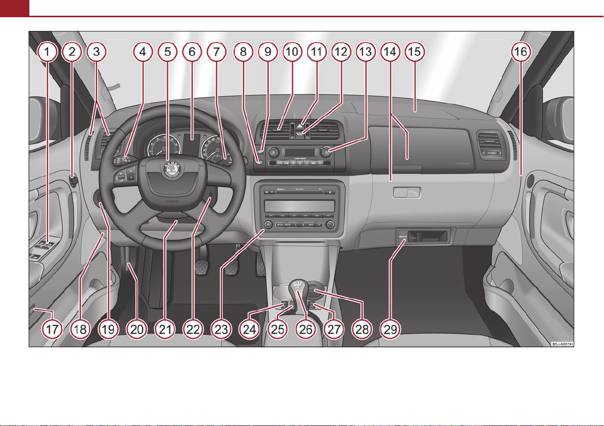
Fig. 1 Certain items of equipment shown in the illustration are only fitted to particular model versions or are optional items of equipment.
Cockpit
Note
A
1
43
A
2
55
A
3
78
A
4
50
92
A
5
119
100
A
6
15
A
7
18
53
A
8
52
A
9
133
A
10
78
A
11
49
A
12
125
A
13
788184
A
14
74
A
15
119
A
16
125
A
17
39
42
A
18
191
A
19
46, 49
A
20
161
A
21
87
A
22
87
A
23A24
59
A
25
38
A
26
90
95
A
27
59
A
28
72
75
A
29
107
Cockpit 9
General view
This overview will help you to quickly familiarise yourself with the
displays and the control elements.
Electric power-operated window* . . . . . . . . . . . . . . . . . . . . . . . . . . . . . . .
Electric exterior mirror adjustment* . . . . . . . . . . . . . . . . . . . . . . . . . . . . .
Air outlet vents . . . . . . . . . . . . . . . . . . . . . . . . . . . . . . . . . . . . . . . . . . . . . . . .
Lever for the multi-functional switch:
Turn signal light, headlight and parking light, headlight flasher . .
Speed regulating system* . . . . . . . . . . . . . . . . . . . . . . . . . . . . . . . . . . . .
Steering wheel:
with horn
with driver airbag . . . . . . . . . . . . . . . . . . . . . . . . . . . . . . . . . . . . . . . . . . .
with pushbuttons for radio, navigation system and mobile phone*
Instrument cluster: Instruments and indicator lights . . . . . . . . . . . . . .
Lever for the multi-functional switch:
Multi-functional indicator* . . . . . . . . . . . . . . . . . . . . . . . . . . . . . . . . . . .
Windshield wiper and wash system . . . . . . . . . . . . . . . . . . . . . . . . . . .
Switch for rear window heater . . . . . . . . . . . . . . . . . . . . . . . . . . . . . . . . . .
Switch for the TCS* . . . . . . . . . . . . . . . . . . . . . . . . . . . . . . . . . . . . . . . . . . . . .
Air outlet vents . . . . . . . . . . . . . . . . . . . . . . . . . . . . . . . . . . . . . . . . . . . . . . . .
Switch for hazard warning lights . . . . . . . . . . . . . . . . . . . . . . . . . . . . . . . . .
Indicator light for a switched off front seat passenger airbag* . . . . . .
Depending on equipment fitted:
Operating controls for the heating . . . . . . . . . . . . . . . . . . . . . . . . . . . .
Operating controls for Climatic* . . . . . . . . . . . . . . . . . . . . . . . . . . . . . .
Operating controls for Climatronic* . . . . . . . . . . . . . . . . . . . . . . . . . . .
Storage compartments on the front passenger side* . . . . . . . . . . . . . .
Front passenger airbag* . . . . . . . . . . . . . . . . . . . . . . . . . . . . . . . . . . . . . . . .
Switch for front passenger airbag* . . . . . . . . . . . . . . . . . . . . . . . . . . . . . . .
Switch depending on equipment fitted:
Unlocking the boot lid* . . . . . . . . . . . . . . . . . . . . . . . . . . . . . . . . . . . . . .
Interior monitor* . . . . . . . . . . . . . . . . . . . . . . . . . . . . . . . . . . . . . . . . . . . .
Fuse box in the dash panel . . . . . . . . . . . . . . . . . . . . . . . . . . . . . . . . . . . . . .
Light switch and headlamp beam adjustment . . . . . . . . . . . . . . . . . . . .
Bonnet release lever . . . . . . . . . . . . . . . . . . . . . . . . . . . . . . . . . . . . . . . . . . . .
Lever for adjusting the steering wheel . . . . . . . . . . . . . . . . . . . . . . . . . . . .
Ignition lock . . . . . . . . . . . . . . . . . . . . . . . . . . . . . . . . . . . . . . . . . . . . . . . . . . .
Depending on equipment fitted:
Radio*
Navigation*
Rocker switch for the heating on the driver's seat* . . . . . . . . . . . . . . . .
Button for the central locking system* . . . . . . . . . . . . . . . . . . . . . . . . . . .
Depending on equipment fitted:
Gearshift lever (manual gearbox) . . . . . . . . . . . . . . . . . . . . . . . . . . . . . .
Selector lever (automatic gearbox*) . . . . . . . . . . . . . . . . . . . . . . . . . . .
Rocker switch for the heating on the front passenger seat* . . . . . . . .
Depending on equipment fitted:
Ashtray* . . . . . . . . . . . . . . . . . . . . . . . . . . . . . . . . . . . . . . . . . . . . . . . . . . . .
Storage compartment . . . . . . . . . . . . . . . . . . . . . . . . . . . . . . . . . . . . . . . .
MDI* . . . . . . . . . . . . . . . . . . . . . . . . . . . . . . . . . . . . . . . . . . . . . . . . . . . . . . . . . .
Cars with factory-fitted radio or navigation system are supplied with separate
instructions for operating such equipment.
The arrangement of the control elements on right-hand drive models may differ to
some extent from that shown in page 8, fig. 1. However the symbols correspond to
the individual control elements.
Using the system Safety Driving Tips General Maintenance Breakdown assistance Praktik Technical Data
The brief instruction10
WARNING
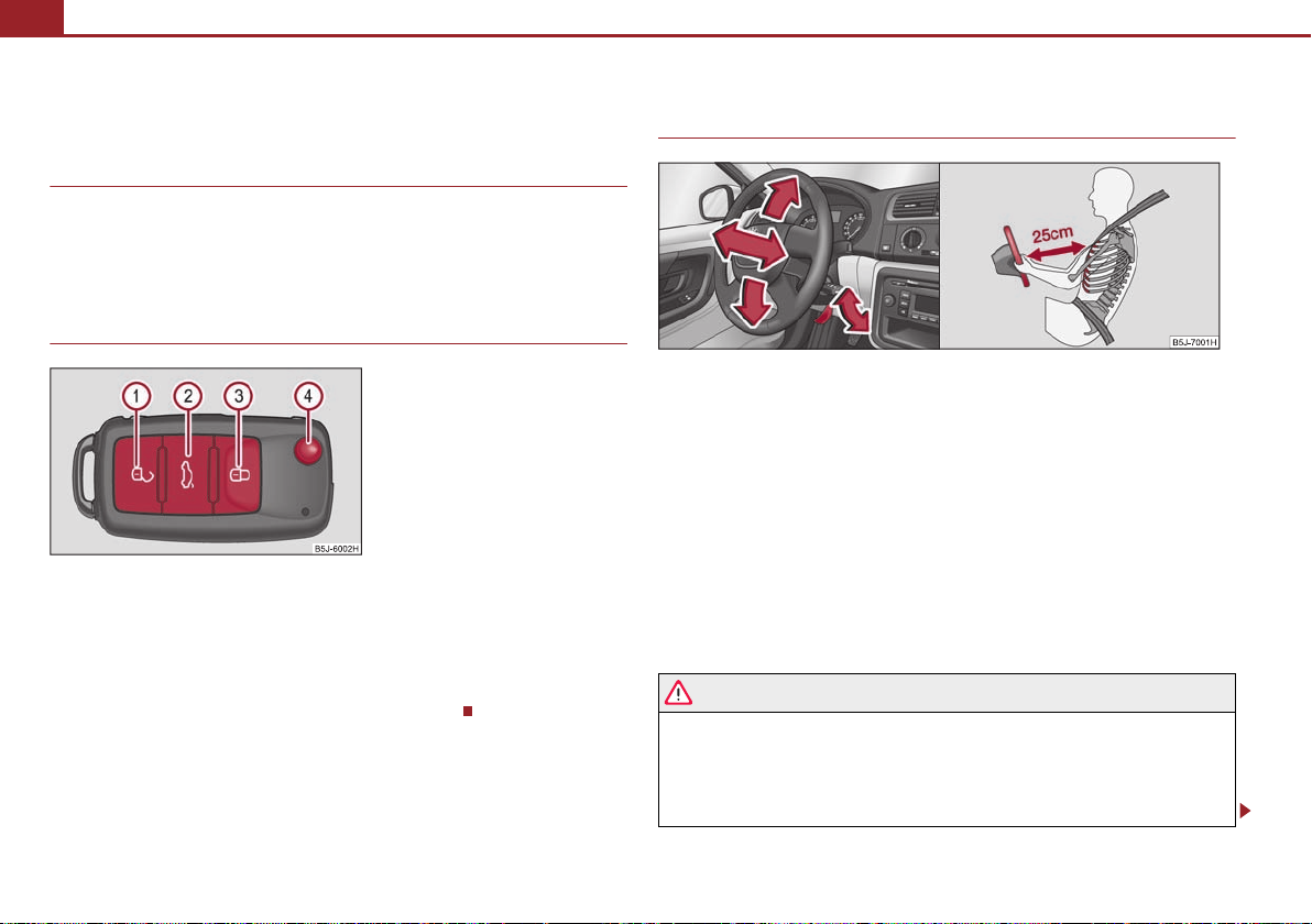
Fig. 2 Remote control key
A1A2A3A
4
The brief instruction
Basic functions and important information
Introduction
The chapter of the brief instruction is only used as a quick reference of
the most important operating elements of the vehicle. It is necessary to
observe all the information which is contained in the following chapters
of the Owner's Manual.
Unlocking and locking the vehicle
Unlocking the vehicle
Unlocking the boot lid
Locking the vehicle
Folding out/folding up of the key
Further information page 40, “Unlocking and locking car”.
Setting steering wheel position
Fig. 3 Adjustable steering wheel: Lever on the steering column / the correct distance of the
driver from the steering wheel
You can set the height and the forward/back position of the steering wheel to the
desired position.
– Pull the lever below the steering column fig. 3 down.
– Set the steering wheel to the desired position (concerning height and forward/back
position).
– Push the lever upwards as far as the stop.
You can set the height and the forward/back position of the steering wheel to the
desired position.
Further information page 87, “Setting steering wheel position”.
Adjust the steering wheel so that the distance between the steering wheel
and your chest is at least 25 cm fig. 3 on the right. Not maintaining this
minimum distance will mean that the airbag system will not be able to properly
protect you - hazard!
You must not adjust the steering wheel when the vehicle is moving!
For safety reasons the lever must always be firmly pushed up to avoid the
WARNING
WARNING
WARNING (continued )
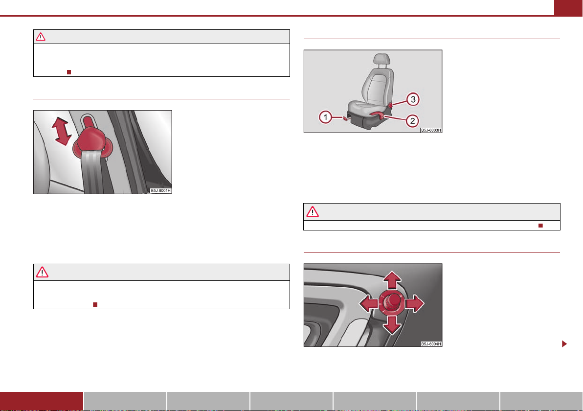
Fig. 4 Front seat: Seat belt height
adjuster
Fig. 5 Controls at sea t
A1A2A
3
Fig. 6 Inner part of door: Rotary knob
steering wheel altering its position unintentionally when driving - risk of
accident!
Seat belt height adjuster
– To adjust the belt height press the height adjuster and move it up or down fig. 4.
– Then pull firmly on the belt to ensure that the seat belt height adjuster has correctly
locked in place.
Further information page 115.
Adjust the height of the belt in such a way that the shoulder part of the belt is
positioned approximately across the middle of your shoulder - on no account
across your neck!
The brief instruction 11
Adjusting the front seats
Adjusting a seat in a forward/back direction
Adjusting height of seat*
Adjust the angle of the seat backrest
Further information page 57, “Adjusting the front seats”.
Only adjust the driver seat when the vehicle is stationary - risk of injury!
Electric exterior mirror adjustment*
Using the system Safety Driving Tips General Maintenance Breakdown assistance Praktik Technical Data
The brief instruction12
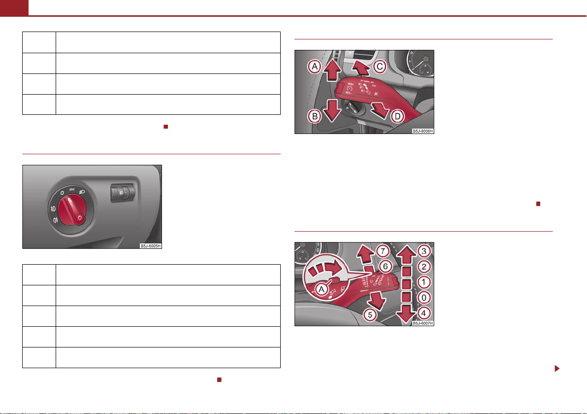
Fig. 7 Dash panel: Light switch
Fig. 8 Turn signal and main beam lever
AAABACA
D
Fig. 9 Windscreen wiper lever
AAA0A
1
Heating of the external mirror
Adjusting the left-hand exterior mirror
Adjusting the right-hand exterior mirror
Switching off operating control
Further information page 55, “Rear mirror”.
Switching lights on and off
Switching off all lights
Switching on side lights
Switching on the low beam and main beam
Turn signal and main beam lever
Turn signal light right
Turn signal light left
Switching over between low beam and main beam lights
Headlight flasher
Further information page 50, “The turn signal and main beam lever ”.
Windscreen wiper lever
Fog lights*
Rear fog light
Further information page 46, “Switching lights on and off ”.
Intermittent switch
Wipers off
Intermittent wipe
The brief instruction 13
A2A3A4A
5A6A7
Fig. 10 Buttons on the driver's door
AAABACADA
S
Slow wipe
Fast wipe
one time wipe
Automatic wipe/wash
Rear window wiper
Intermittent wipe - every 6 seconds
Automatic wipe/wash
Further information page 53, “Windshield wiper”.
Power windows*
Button for the power window in the driver's door
Button for the power window in the front passenger's door
Button for the power window in the rear door on the right*
Button for the power window in the rear door on the left*
Safety pushbutton*
Further information page 43, “Buttons for electrical power windows”.
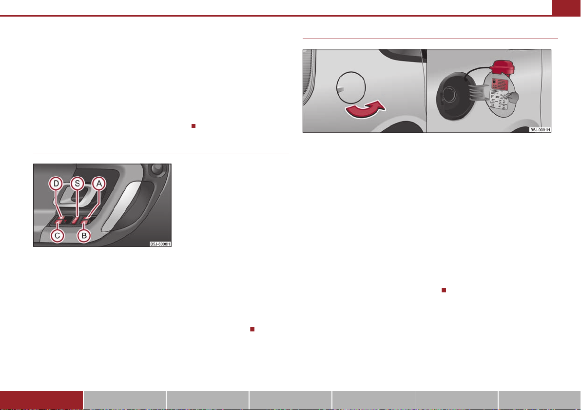
Refuelling
Fig. 11 Right rear side of the vehicle: Fuel filler flap / fuel filler flap with cap unscrewed
Opening the fuel filler cap
– Open the fuel filler flap with the hand.
– Unlock the fuel filler cap on the fuel filler tube to the left using the vehicle key.
– Unscrew the fuel filler cap anti-clockwise and place the fuel filler cap from above
on the fuel filler flap fig. 11 on the right.
Closing fuel filler cap
– Screw on the cap by turning it to the right until it is heard to lock.
– Lock the fuel filler cap on the fuel filler tube by turning the vehicle key to the right
and withdraw the key.
– Press the fuel tank flap closed.
Further information page 159, “Refuelling”.
Using the system Safety Driving Tips General Maintenance Breakdown assistance Praktik Technical Data
The brief instruction14
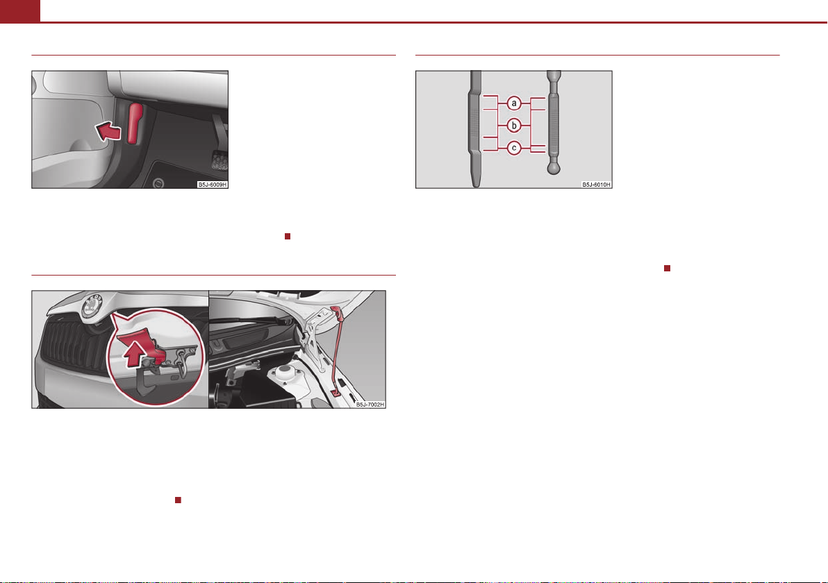
Fig. 12 Bonnet release lever
Fig. 14 Dipstick
AaAbA
c
Bonnet remote release
– Pull the unlocking lever below the dash panel on the driver's side fig. 12.
Further information page 161, “Bonnet remote release”.
Opening the bonnet
Fig. 13 Radiator grille: Locking lever / securing the bonnet with the bonnet support
– Pull on the locking lever fig. 13, the bonnet is then unlocked.
– Take the bonnet support out of its holder and set it in the opening designed for it
fig. 13 on the right.
Inspecting the engine oil level
Engine oil must not be refilled.
Engine oil can be refilled.
Engine oil must be refilled.
Further information page 163, “Check engine oil level”.
Further information page 161.
Instruments and warning lights
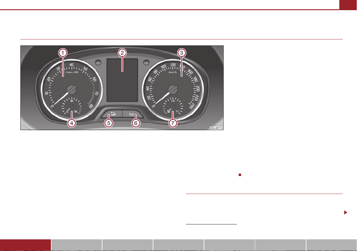
Fig. 15 Instrument cluster
A
1
A
2
A
3
A
4A5
A6A
7A1
Overview of the instrument cluster
Instruments and warning lights 15
Engine revolutions counter
Display
with counter for distance driven page 17
with Service Interval Display page 17
with digital clock page 18
with Multi-functional indicator* page 18
with Information display* page 22
Speedometer page 16
Coolant temperature gauge* page 16
Button for display mode:
Set hours / minutes
Activating / deactivating the second speed in mph or km/h*
Service interval - Display of the remaining number of days, kilometres or miles
to the next Inspection Service / Reset*
Using the system Safety Driving Tips General Maintenance Breakdown assistance Praktik Technical Data
1)
Button for:
Reset trip counter for distance driven
Resetting Service Interval Display
Set hours / minutes
Activate / deactivate display mode
Fuel gauge* page 16
Engine revolutions counter
The red zone of the rev counter scale fig. 15 indicates the range in which the
engine control unit begins to limit the engine speed. The engine control unit restricts
the engine speed to a steady limit value.
1)
Valid for countries where the values are indicated in British measuring units.
Instruments and warning lights16
For the sake of the environment
Note
WARNING
Caution
A4A
7
Shift into the next higher gear or select the selector lever position D of the automatic
gearbox before reaching the red zone of the rev counter scale.
Avoid high engine speeds during the driving time and before the engine has been
warmed up to operating temperature page 141.
Sh ifti ng to a hi gher gea r in g ood t ime help s to reduce the fuel consumption, minimises
operating noise levels, protects the environment and contributes to a longer life and
reliability of the engine.
Speedometer
Warning against excessive speeds*
An acoustic warning signal will sound when the vehicle speed exceeds 120 kilometres
per hour. The acoustic warning signal will switch off again when the vehicle speed goes
below this speed limit.
This function is only valid for some countries.
Coolant temperature gauge*
The coolant temperature gauge page 15, fig. 15 operates only when the ignition
is switched on.
In order to avoid any damage to the engine, please pay attention to the following notes
regarding the temperature ranges:
Cold range
If the pointer is in the left-hand area of the scale it means that the engine has not yet
reached its operating temperature. Avoid running at high engine speeds, at full throttle
and at severe engine loads.
The operating range
The engine has reached its operating temperature as soon as the pointer moves into
the mid-range of the scale. The pointer may also move further to the right at high
engine loads and high outside temperatures. This is not critical provided the warning
symbol in the instrument cluster does not flash.
If the symbol in the instrument cluster flashes it means that either the coolant
temperature is too high or the coolant level is too low. Observe the guidelines
page 28, “Coolant temperature/ Coolant quantity ”.
Pay attention to the warning notes page 162, “Working in the engine
compartment” before opening the bonnet and inspecting the coolant level.
Additional headlights and other attached components in front of the fresh air inlet
impair the cooling efficiency of the coolant. There is then a risk of the engine overheating at high outside temperatures and high engine loads!
Fuel gauge*
The fuel gauge page 15, fig. 15 only operates when the ignition is switched on.
The fuel tank has a capacity of about 55 litres. The warning symbol in the instrument
cluster lights up when the pointer reaches the reserve marking. There are now about 7
litres of fuel remaining in the tank. This symbol is a reminder for you, that you must
refue l.
The following will be displayed in the information display*:
Please refuel!
An audible signal sounds as an additional warning signal.
On some vehicles, the fuel gauge is shown in the display of the instrument cluster.
Caution
Never run the fuel tank completely empty! The irregular supply of the fuel system can
WARNING
Note
A
6
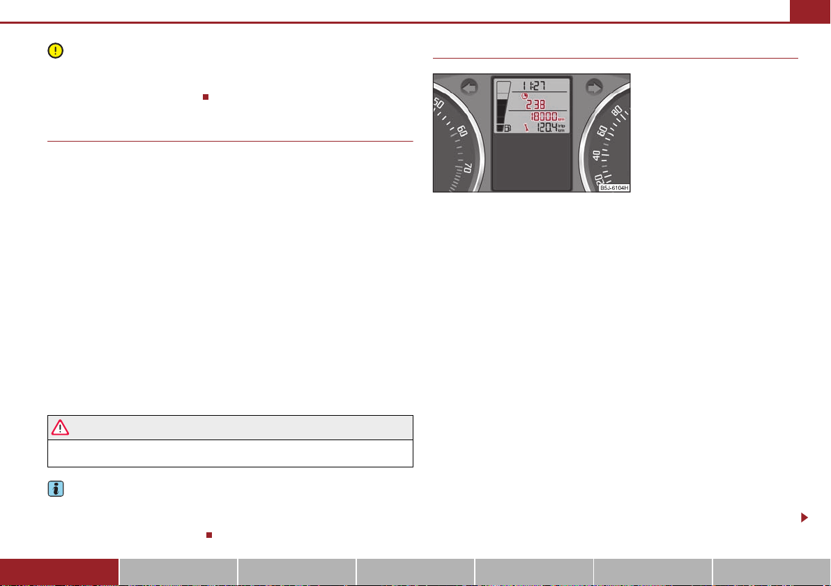
Fig. 16 Service Interval Display: Note
A
5
lead to irregular running of the engine. Unburnt fuel may get into the exhaust system
and damage the catalytic converter.
Counter for distance driven
The counter for the distance driven is located in the bottom area of the display. The
distance which you have driven with your vehicle is shown in kilometres (km). In some
countries the measuring unit “mile” is used.
Reset button
If you hold the reset button page 15, fig. 15 pressed for about 1 second, the trip
counter is set back to zero.
Trip counter for distance driven
The trip counter indicates the distance which you have driven since it was last reset in steps of 100 metres or 1/10 of a mile.
Counter for distance driven
The counter for distance driven indicates the total distance in kilometers or miles
which the vehicle has been driven.
Fau lt dis play
If there is a fault in the instrument cluster, the constant text Error appears in the display.
Have the fault rectified as soon as possible by a specialist workshop.
Never seek to adjust the trip counter for distance driven while driving for safety
reasons !
If vehicles which are fitted with the information display* the display of the second
speed is activated in mph or km/h, this driving speed is indicated instead of the
counter for the total distance driven.
Instruments and warning lights 17
Service Interval Display
Depending on the equipment installed in the vehicle, the text can differ on the display.
Service Interval Display
Before the next service interval a key symbol and the remaining kilometers are
indicated after switching on the ignition fig. 16. At the same time, a display appears
regarding the remaining days until the next service interval.
The following will be displayed in the information display*:
Service in ... km or... days
The kilometre indicator or the days indicator reduces in steps of 100 km. or days until
the service due date is reached.
A flashing key symbol and the text Service appears in the display for 20 seconds
as soon as the due date for the service is reached.
The following will be displayed in the information display*:
Service now!
Display regarding the distance and days until the following service interval
You can use the button to display the remaining distance driven and the days until
the next service interval page 15.
A key symbol and a display regarding the remaining kilometers appear for 10
second in the display. At the same time, a display appears regarding the remaining days
until the next service interval.
Using the system Safety Driving Tips General Maintenance Breakdown assistance Praktik Technical Data
Instruments and warning lights18
Caution
Note
WARNING
A
6
A5A6A
5
A
6
On vehicles which are equipped with information display*, you can call up this information in the menu SETUP page 22.
The following will be displayed in the information display* for 10 seconds:
Service in ... km or... days
Resetting Service Interval Display
It is only possible to reset the Service Interval Display, if a service message or at least a
pre-warning is shown on the display of the instrument cluster.
We recommend having this resetting performed by a specialist garage.
The specialist garage:
resets the memory of the display after the appropriate inspection;
makes an entry in the Service schedule;
affix the sticker with the entry of the following service interval to the side of the
dash panel on the driver's side.
Reset the service interval displays by using the reset button page 15 on the trip
counter.
On vehicles which are equipped with information display*, you can call up this information in the menu SETUP page 22.
We recommend that you do not reset the Service Interval Display yourself otherwise
this can result in the service interval display being incorrectly set, which may also result
in problems with operation of your vehicle.
Never reset the display between service intervals otherwise this may result in
incorrect readouts.
information is retained in the Service Interval Display also after the battery of the
vehicle is disconnected.
If the instrument cluster is exchanged after a repair, the correct values must be
entered in the counter for the Service Interval Display. This work is carried out by a
specialist garage.
The data displayed is the same after resetting the display with flexible service inter-
vals (QG1) using the reset button as that for a vehicle with fixed service inter vals (QG2).
We therefore recommend having the Service Interval Display reset only by an authorised Škoda Service Partner who is familiar with the procedure for resetting the display
with a vehicle system tester.
Please refer to the brochure Service schedule for extensive information about the
service intervals.
Digital clock
The time is set with the buttons and page 15, fig. 15.
Select the display which you wish to change with the button and carry out the
change with the button .
On vehicles which are fitted out with the information display*, it is possible to set the
time in the menu Time page 24.
The clock should not be adjusted while driving for safety reasons but only when
the vehicle is stationary!
Multi-functional indicator (onboard computer)*
Introduction
The multi-functional indicator appears in the display page 19, fig. 17 or in the information display page 22 depending on the equipment fitted to your vehicle.
The multi-functional indicator offers you a range of useful information.
The outside temperature page 20
Driving time page 20
Current fuel consumption page 20
Average fuel consumption page 20
Instruments and warning lights 19
Note
Note
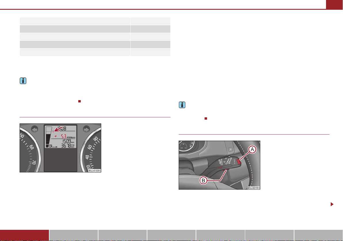
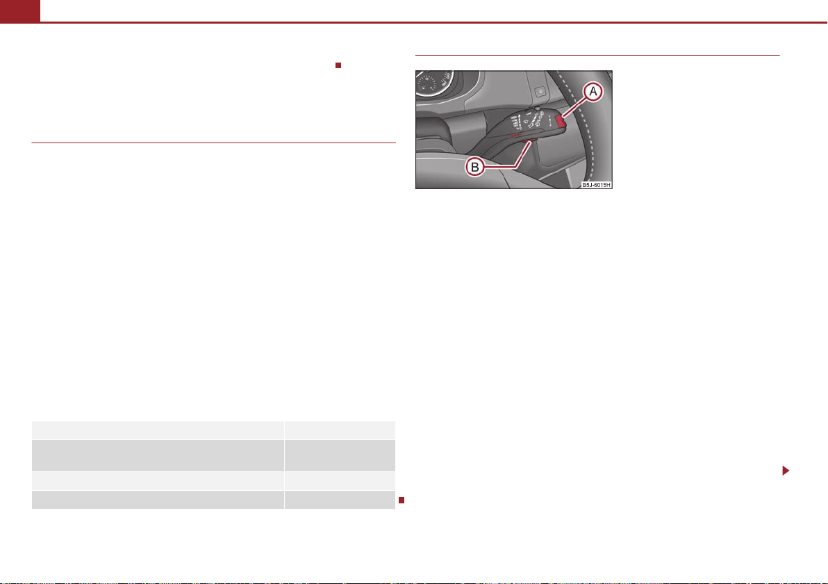
Fig. 17 Multi-functional indicator
A
B
Fig. 18 Multi-functional indicator:
Control elements
AAA
B
Range page 21
Distance driven page 21
Average speed page 21
Current speed* page 21
Warning against excessive speeds* page 21
On vehicles which are fitted out with information display*, it is possible to switch off
the display of some information.
In certain national versions the displays appear in the Imperial system of measures.
If the display of the second speed is activated in mph, the current speed* is not
indicated in km/h on the display.
Memory
The multi-functional indicator is equipped with two automatic memories. The
selected memory is displayed in the middle of the display field fig. 17.
The data of the single-trip memory (memory 1) is shown if a 1 appears in the display.
A 2 shown in the display means that data relates to the total distance memory
(memory 2).
Switching over the memory takes place with the button fig. 18 on the windshield
wiper lever.
Single-trip memory (memory 1)
The single-trip memory collates the driving information from the moment the ignition
is switched on until it is switched off. New data will also flow into the calculation of the
current driving information if the trip is continued within 2 hours after switching off
the ignition. The memory will be is automatically erased, on the other hand, if the trip
is interrupted for more than 2 hours.
Total-trip memory (memory 2)
The total distance driven memory gathers data from any number of individual journeys up to a total of 19 hours and 59 minutes driving or 1.999 kilometres driven and
on vehicles which are fitted with information display* up to a total of 99 hours and 59
minutes driving or 9.999 kilometres driven.
The total-trip memory will not, contrary to the single-trip memory, be deleted after a
period of interruption of driving of 2 hours.
All information in the memory 1 and 2 is erased if the battery of the vehicle is
disconnected.
Using the system
The rocker switch and the button are located in the grip of the window wiper
lever fig. 18.
Using the system Safety Driving Tips General Maintenance Breakdown assistance Praktik Technical Data
Instruments and warning lights20
WARNING
A
BAA
ABABA
A
WARNING (continued )
ABA
B
Selecting the memory
– Short-term pressing of the button on the windshield wiper lever allows to s elect
the desired memory.
Selecting the functions
– Press the top or bottom rocker switch for longer than 0.5 seconds. In this way,
call up in sequence the individual functions of the multi-functional indicator.
Setting function to zero
– Select the memory you want.
– Press button for more than 1 second.
The following readouts of the selected memory will be set to zero by button :
average fuel consumption;
distance driven;
average speed;
Driving time.
You can only operate the multi-functional indicator when the ignition is switched on.
After the ignition is switched on, the function displayed is the one which you last
selected before switching off the ignition.
Outside temperature
The outside temperature appears in the display when the ignition is switched on.
If the outside temperature drops below +4°C, a snow flake symbol (warning signal for
ice on the road) appears in front of the temperature indicator and flashes for 10
seconds, then remains displayed together with the outside temperature. At the same
time an audible signal sounds. After pressing the rocker switch on the windshield
wiper lever page 19, fig. 18, the function which was shown last is indicated.
Do not only rely upon the information given on the outs ide temperature display
that there is no ice on the road. Please note that black ice may also be present
on the road surface even at temperatures around +4°C - warning, drive with
care!
Driving time
The driving time which has elapsed since the memory was last erased, appears in the
display page 19. If you wish to calculate the driving time from a particular time of
day you must first erase the memory at this moment in time by pressing the button
page 19, fig. 18.
The maximum time indicated in both switch positions is 19 hours and 59 minutes and
on vehicles which are fitted with information display*, it is 99 hours and 59 minutes.
The indicator is set back to null if this period is exceeded.
Current fuel consumption
The current fuel consumption level is shown in the display in litres/100 km. This information can help you to adapt your style of driving to the fuel consumption you wish to
achieve.
The display appears in litres/hour if the vehicle is stationary or driving at a low speed.
The indicated value will be updated every 0.5 seconds while you are driving.
Average fuel consumption
The average fuel consumption since the memory was last erased is shown in the
display in litres/100 km page 19. This information can help you to adapt your style
of driving to the fuel consumption you wish to achieve.
If you wish to determine the average fuel consumption over a certain period of time
you must first erase the memory at the start of the new measurement using the button
page 19, fig. 18. A zero appears in the display for the first 300 m you drive after
erasing the memory.
The indicated value will be updated every 5 seconds while you are driving.
Instruments and warning lights 21
Note
ABA
B
A
2
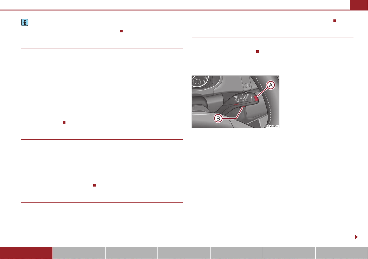
Fig. 19 Multi-functional indicator:
Control elements
A
BAAABAB
The indicated value will be updated every 5 seconds while you are driving.
The amount of fuel consumed will not be indicated.
Range
The estimated range in kilometres is shown on the display. It indicates the distance you
can still drive with your vehicle based on the present level of fuel in the tank for the
same style of driving.
The readout is shown in steps of 10 km. After lighting up of the indicator light for the
fuel reserve the display is shown in steps of 5 km.
The fuel consumption for the last 50 km is taken as a basis for calculating the range. If
you drive in a more economical manner from this moment on, the range will be
increased accordingly.
If the memory is set to zero (after disconnecting the battery), the fuel consumption of
10 ltr./100 km is calculated for the range; afterwards the value is adapted accordingly
to the style of driving.
Distance driven
The distance driven since the memory was last erased appears in the display
page 19. If you wish to calculate the distance driven as of a particular time, you must
erase the memory at this moment in time by pressing the button on the windshield
wiper lever page 19, fig. 18.
The maximum distance indicated in both switch positions is 1.999 kilometres, on vehicles which are fitted with information display* it is 9.999 kilometres. The indicator is s et
back to null if this period is exceeded.
Average speed
The average speed since the memory was last erased is shown in the display in
km/hour page 19. If you wish to determine the average speed over a certain period
of time, you must erase the memory at the start of the new measurement by pressing
the button on the windshield wiper lever page 19, fig. 18.
A zero appears in the display for the first 100 m you drive after erasing the memory.
Current speed*
The current speed which is identical to the display of the speedometer, is indicated on
the display page 15, fig. 15.
Warning against excessive speeds*
This function enables you to set a speed limit, e.g. if you drive in town. A text in the
display is intended to draw your attention to the fact that you have exceeded the set
speed limit.
Warning against excessive speeds
– Select the menu point Speed warning --- km/h (warning at --- km/h)..
– Drive e.°g at a speed of 50 km/h.
– Press button fig. 19. Speed warning 50 km/h (warning at 50 km/h) is
displayed in the information display*. You can increase or reduce this value with
the aid of the button .
– After repeated pressing of the button , the value is stored.
After pressing again, the value is erased and --- is shown in the information display*.
If you now exceed the set speed limit, Speed 50°km/h exceeded will be shown on the
display. This text is shown until you lower the speed below the set limit or you switch
off the displayed text with the button fig. 19.
Using the system Safety Driving Tips General Maintenance Breakdown assistance Praktik Technical Data
Instruments and warning lights22
Fig. 20 Information display: Control
elements
A
A
A
AAB
An audible signal sounds as an additional warning signal.
The set speed limit remains stored even after switching off the ignition.
MAXI DOT display (information display)*
Introduction
The information display provides you with information in a convenient way
concerning the current operating state of your vehicle. The information system also
provides you with data (depending on the equipment installed in the vehicle) relating
to the radio, mobile phone, multi-functional indicator, navigation system, the unit
connected to the MDI input and the automatic gearbox.
Certain functions and operating conditions are always being checked on the vehicle
when the ignition is switched on and also while driving.
Functional faults, if required repair work and other information are indicated by red
symbols page 23 and yellow symbols page 24.
Lighting up of certain symbols is combined with an acoustic warning signal.
Information and texts giving warnings are also shown in the display page 25.
The display of text is possible in the following languages:
Czech, English, German, French, Italian, Spanish, Portuguese, Russian and Chinese.
You can select the desired language in the setting menu.
The following information can be shown in the display (depending on the equipment
installed on the vehicle):
Main menu page 22
Door, luggage compartment door and bonnet ajar warning
Service Interval Display page 17
Selector lever position for an automatic gearbox page 94
page 23
Main menu
– You can activate the MAIN MENU by pressing the rocker switch fig. 20 for
more than 1 second.
– You can select individual menu points by means of the rocker switch . When the
pushbutton is briefly pressed, the information you have selected is displayed.
You can select the following information (depending on the equipment installed on
the vehicle):
MFD (Onboard computer) page 18
Audio*
Navigation*
Phone* page 101
Ve hicle s tatus page 23
Setup page 24
The menu point Audio is only then displayed when the factory-fitted Radio* is
switched on.
The menu point Navigation is only then displayed when the factory-fitted Navigation
system* is switched on.
Note
If warning messages are shown in the information display page 23, these
A
B
mes sage s can b e conf irme d with the b utton on t he win dshie ld wi per le ver i n order
to call up the main menu.
If you do not activate the information display at that moment, the menu shifts to
one level higher every 10 seconds.
The operation of the factory-fitted radio* or the navigation system* is described in
separate operating instructions to be found in the on-board literature.
Door, luggage compartment door and bonnet ajar warning
The door, luggage compartment and bonnet ajar warning lights up if at leas t one door,
the luggage compartment or bonnet are not closed. The symbol indicates which door
is still open or whether the luggage compartment door or bonnet is not closed.
The symbol goes out as soon as the doors, luggage compar tment door and bonnet are
completely closed.
A warning signal sounds if the car is driven at a speed of more than 6km/hour and if
the engine or the luggage compartment door is open.
Auto Check Control
Car state
The Auto Check Control carries out a check of certain functions and vehicle components. The check is performed constantly when the ignition is switched on, both when
the vehicle is stationary, as well as when driving.
Some operational faults, urgent repairs, service work or other information appear in
the display of the instrument cluster. The displays are shown with a red or yellow light
symbol depending on the priority of the message.
The red symbols indicate danger (priority 1) while the yellow symbols indicate a
warning (priortity 2). Information for the driver may also appear in addition to the
symbols page 25.
Instruments and warning lights 23
Shown in the menu Vehicle status, if there is at least one error message. After selecting
this menu the first of the error messages is displayed. Several error messages are
shown on the display under the message e.g. 1/3. This indicates that the first of a total
of three error messages is displayed. The respective messages are displayed one after
the other in an interval of 5 seconds. Check as soon as possible the displayed error
messages.
As long as the operational faults are not rectified, the symbols are always indicated
again. After the first display, the symbols are indicated without information for the
driver.
If a fault occurs, a warning signal will also sound in addition to the symbol and text in
the display:
Priority 1 - three warning signals
Priority 2 - one warning signal
Red symbols
A red symbol signals danger.
– Bring the vehicle to a stop.
– Switch the engine off.
– Investigate the function indicated.
– Obtain professional assistance.
Meaning of the red symbols:
Three successive warning signals will sound if a red symbol appears.
Engine oil pressure too low page 28
Overheated clutches of the automatic gearbox DSG*
page 94
Using the system Safety Driving Tips General Maintenance Breakdown assistance Praktik Technical Data
Instruments and warning lights24
Yellow symbols
A yellow symbol signals a warning.
Check the relevant function as soon as possible.
The meaning of the yellow symbols:
One warning signal will sound if a yellow symbol appears.
If several operational faults of priority 2 exist, the symbols appear one after the other
and are each illuminated for about 5 seconds.
Check engine oil level,
engine oil sensor faulty
page 28
Setup
You can change certain settings by means of the information display. The current
setting is shown on the information display in the respective menu at the top below the
line.
You can select the following information (depending on the equipment installed on
the vehicle):
Language
MFD Data (MFA DATA)
Time
Winter tyres
Units
Alt. speed dis.
Service Interval (Service)
Factory Setting
Back
After selecting the menu point Back you will reach one level higher in the menu.
Language
Here you can set in which language the warning and information texts should be
displayed.
Displays of the MFA
Here you can switch off or on certain displays of the multi-functional indicator.
Time
Here you can set the time, the time format (12 or 24 hour indicator) and the time
change summer/winter time.
Winter tyres
Here you can set at which speed a warning signal should sound. This function is used
for e.g winter tyres with the permissible maximum speed less than the maximum
speed of the vehicle.
When exceeding the speed, the following is displayed on the information display*:
Snow tyres max. speed ... km/h (Winter tyres maximum ... km/h)
Measures
Here you can set the units for temperature, consumption and distance driven.
Second speed
Here you can switch on the display of the second speed in mph or in km/h2).
Service
Here you can have the kilometers still to be driven and the days until the following
service interval shown and the Service Interval Display reset.
Factory Setting
After selecting the menu point Factory Setting the factory setting of the information
display is established again.
2)
Valid for countries where the values are indicated in British measuring units.
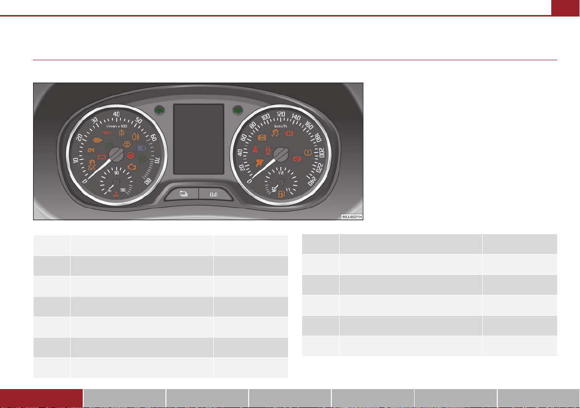
Warning lights
Fig. 21 Instrument cluster with warning lights
Overview
The warning lights indicate certain functions or faults.
Turn signal lights (to the left) page 26
Turn signal lights (to the right) page 26
Main beam light page 26
Instruments and warning lights 25
Fog lights* page 27
Electrohydraulic power steering page 27
EPC fault light (petrol engine) page 27
Glow plug system (diesel engine) page 28
Low beam light page 26
Rear fog light page 27
Failure of the light bulbs page 27
Dynamo page 27
Using the system Safety Driving Tips General Maintenance Breakdown assistance Praktik Technical Data
Coolant temperature/coolant level page 28
Fuel reserve page 28
Instruments and warning lights26
WARNING
Note
Engine oil page 28
Open door page 29
Fluid level in windshield washer system* page 29
Control system for exhaust page 29
Traction control system (TCS)* page 30
Tyre pressure monitoring system* page 30
Selector lever lock* page 30
Traction control system (TCS)* page 30
Electronic stability programme (ESP)* page 30
Antilock brake system (ABS) page 31
Brake system page 31
Cruise control system* page 32
Airbag system page 32
Diesel particle filter* (diesel engine) page 32
If you do not pay attention to the warning lights coming on and the corre-
sponding descriptions and warning notes, this may result in severe body injuries or major vehicle damage.
The engine compartment of your car is a hazardous area. There is a risk of
injuries, scalding, accidents and fire when working in the engine compartment,
e.g. inspecting and replenishing oil and other fluids. It is also essential to
observe all warnings page 162, “Working in the engine compartment”.
Arrangement of the indicator lights depends on the model and model version.
Operational faults are shown in the instrument cluster as red symbols (priority 1 -
danger) or yellow symbols (priority 2 - warning).
Turn signal system
Either the left or right indicator light flashes depending on the position of the turn
signal lever.
The indicator light flashes at twice its normal rate if a turn signal light fails.
Switching off the hazard warning light system is switched on will cause all of the turn
signal lights as well as both indicator lights to flash.
Further information about the turn signal system page 50.
Main beam
The indicator light comes on when the main beam is selected or also when the
headlight flasher is operated.
Further information about the main beam page 50.
Seat belt warning light page 33
Low beam
The warning light comes on when low beam is selected page 46.
Instruments and warning lights 27
Caution
WARNING
Note
Rear fog light
The warning light comes on when the rear fog lights are operating page 48.
Bulb failure
The warning light comes on if a bulb is faulty:
up to 2 seconds after the ignition is switched on;
when switching on the defective light bulb.
The following text e.g will be displayed in the information display*:
Check front right dipped beam!
The rear side lights and the licence plate lighting require several light bulbs. The indicator light only lights up if all light bulbs of the licence plate lighting or the parking
light (in one rear light unit) are defective. Check regularly the function of the light
bulbs.
Alternator
The warning light comes on after the ignition has been switched on. It should go
out after the engine has started.
If the warning light does not go out after the engine has started, or comes on when
driving, drive to the nearest specialist garage. The vehicle battery will be discharged in
this case so switch off all non-essential electrical components.
If the warning light comes on when driving and in addition the warning light
(cooling system fault) also comes on in display, you must then stop the car immediately and switch the engine off - risk of engine damage!
Fog lights*
The warning light comes on when the fog lights are operating page 48.
Electrohydraulic power steering
The warning light comes on for a few seconds when the ignition is switched on.
If the warning light after switching on the ignition or when driving lights up continuously, a fault exists in the electrohydraulic power steering. The power steering operates
with reduced steering assist or is completely without function.
Further information page 137.
Contact your specialist garage if the power steering is defective.
If the yellow warning light goes out after starting the engine again and a short
drive, it is not necessary to visit a specialist garage.
If the batt ery has been disconnected and reconnected, the yellow warning light
comes on after switching on the ignition. The warning light must go out after driving a
short distance.
There is no power-assisted steering support when the vehicle is being towed
without the engine running or when the power-assisted steering is defect. The vehicle
is fully steerable however. There is however increased force required to turn the
steering wheel.
EPC fault light (petrol engine)
The (Electronic Power Control) warning light comes on for a few seconds when the
ignition is switched on.
If the warning light flashes after starting the engine or flashes while driving, a fault
exists in the engine control system. The engine management system selects an emergency programme which enables you to drive to the nearest specialist garage by
adopting a gentle style of driving.
The following text will be displayed in the information display*:
Engine fault: Workshop!
Using the system Safety Driving Tips General Maintenance Breakdown assistance Praktik Technical Data
Instruments and warning lights28
WARNING
Glow plug system (diesel engine)
The warning light lights up for a cold engine when switching on the ignition (preheat position) 2 page 87. Start the engine after the indicator light goes out.
The glow plug indicator light will come on for about 1 second if the engine is at a
normal operating temperature or if the outside temperature is above +5°C. This
means that you can start the engine right away.
There is a fault in the glow plug system if the warning light does not come on or
lights up continuously; contact a specialist garage as soon as possible to obtain
assistance.
If the warning light begins to flash while driving, a fault exists in the engine
control. The engine management system selects an emergency programme which
enables you to drive to the nearest specialist garage by adopting a gentle style of
driving.
The following text will be displayed in the information display*:
Engine fault: Workshop!
Coolant temperature/ Coolant quantity
The warning light lights up until the engine reaches operating temperature3). Avoid
running at high engine speeds, at full throttle and at severe engine loads.
The warning light comes on for a few seconds when the ignition is switched on.
The coolant temperature is too high or the coolant level too low if the warning light
lights up or flashes while driving.
3 peeps sound as an additional warning signal.
In this case stop and switch the engine off and check the coolant level; top up the
coolant as necessary page 166, “Replenishing the coolant”.
Do not continue your journey if for some reason it is not possible under the conditions prevailing to top up with coolant. Keep the engine switched off and obtain
professional assistance from a specialist garage, otherwise it could lead to severe
engine damage.
3)
Not valid for vehicles with information display.
If the coolant is within the specified range, the increased temperature may be caused
by an operating problem at the coolant fan. Check the fuse for the coolant fan, replace
it if necessary page 194, “Fuse assignment at the battery (manual gearbox, automatic gearbox DSG)”.
If the warning light does not go out although the coolant is at the correct level and
also the fuse of the fan is in proper order, do not continue driving. Contact a specialist
garage to obtain assistance.
Please also refer to the additional instructions page 165, “Cooling system”.
The following text will be displayed in the information display*:
Check coolant! Owner's manual
If you must stop for technical reasons, then park the vehicle at a safe distance
from the traffic and switch off the engine and switch on the hazard warning light
system page 49, “Switch for hazard warning lights ”.
Fuel reserve
The warning light comes on, if the fuel level is less than 7 litres.
An audible signal sounds as an additional warning signal.
The following text will be displayed in the information display*:
Please refuel! Range...km
Engine oil
The warning light lights up red (low oil pressure)
The warning light comes on for a few seconds 4) when the ignition is switched on.
Stop the vehicle and switch the engine off if the warning light does not go off after
the engine has started or flashes while driving. Check the oil level and top up with oil
as necessary page 163.
4)
The warning light on vehicles fitted with information display does not come on after switching the ignition on, but only if a fault exists or the engine oil level is too low.
Instruments and warning lights 29
3 peeps sound as an additional warning signal.
Do not continue your journey if for some reason it is not possible under the conditions prevailing to top up with oil. Keep the engine switched off and obtain profes-
sional assistance from a specialist garage, otherwise it could lead to severe engine
damage.
Do not drive any further if the warning light flashes even if the oil is at the correct
level. Do not run the engine not at idling speed either. Contact the nearest specialist
garage to obtain professional assistance.
The following text will be displayed in the information display*:
Oil Pressure Engine off! Owner's manual!
The warning light
If the warning light lights up yellow, the quantity of oil in the engine is probably too low.
Check as soon as possible the oil level or top up page 163 with engine oil.
A peep sounds as an additional warning signal.
The following text will be displayed in the information display*:
Check oil level!
The warning light will go out if the bonnet is left open for more than 30 seconds. If no
engine oil has been replenished, the warning light will come on again after driving
about 100 km.
The warning light flashes yellow* (engine oil level sensor faulty)
A fault on the engine oil level sensor is indicated additionally by an audible signal and
the warning light coming on several times after the ignition has been switched on.
In this case have the engine inspected without delay by a specialist garage.
The following text will be displayed in the information display*:
Oil sensor Workshop!
lights up yellow* (oil quantity too low)
WARNING
If you must stop for technical reasons, then park the vehicle at a safe
distance from the traffic and switch off the engine and switch on the hazard
warning light system page 49.
WARNING (continued )
The red oil pressure light is not an oil level indicator! One should there-
fore check the oil level at regular intervals, preferably after every refueling stop.
Pay attention to the following instructions page 162, “Working in the
engine compartment” before checking the coolant fluid level and opening the
bonnet.
Open door
The warning light comes on if one or several doors are opened or if the boot lid is
opened. If one of the doors opens while driving, the warning light lights up and an
audible signal sounds.
The warning light comes on even when the ignition is switched off. The warning light
lights up for a maximum of 5 minutes.
On ve hic le s wi th inf or mat io n di sp la y* t hi s wa rning light is replaced by a vehicle symbol
page 23.
Windshield washer fluid level*
The warning light comes on when the ignition is switched on if there is insufficient
fluid in the windshield washer system. Top up with liquid page 172.
The following text will be displayed in the information display*:
Top up wash fluid!
Control system for exhaust
The warning light comes on after the ignition has been switched on.
If the warning light does not go out after starting the engine or it lights up when driving,
a fault exists in an exhaust relevant component. The engine management system
selects an emergency programme which enables you to drive to the nearest specialist
garage by adopting a gentle style of driving.
Using the system Safety Driving Tips General Maintenance Breakdown assistance Praktik Technical Data
 Loading...