

Page 1

Service
GETtheMANUALS.org
Workshop Manual
Rapid NH 2014 ➤
Rapid Spaceback 2014 ➤
Body Work
Edition 10.2018
Service Department. Technical Information
Page 2

List of Workshop Manual Repair Groups
GETtheMANUALS.org
Re pa ir G ro up
50 - Body - front
55 - Bonnet, rear lid
57 - Front doors, door components, central locking
58 - Rear doors, door components
60 - Sunroof
63 - Bumpers
64 - Glazing
66 - Exterior equipment
68 - Interior equipment
69 - Passenger protection
70 - Trim, insulation
72 - Seat frames
74 - Seat - padding, covers
Service
Technical information should always be available to the foremen and mechanics, because their
careful and constant adherence to the instructions is essential to ensure vehicle road-worthiness and
safety. In addition, the normal basic safety precautions for working on motor vehicles must, as a
matter of course, be observed.
Page 3

Rapid NH 2014 ➤ , Rapid Spaceback 2014 ➤
GETtheMANUALS.org
Body Work - Edition 10.2018
Contents
50 - Body - front
1 Front body
1.1 Tools . . . . . . . . . . . . . . . . . . . . . . . . . . . . . . . . . . . . . . . . . . . . . . . . . . . . . . . . . . . . . . . . . . 1
1.2 Lock carrier with components parts . . . . . . . . . . . . . . . . . . . . . . . . . . . . . . . . . . . . . . . . . . 1
1.3 Service position . . . . . . . . . . . . . . . . . . . . . . . . . . . . . . . . . . . . . . . . . . . . . . . . . . . . . . . . . . 2
1.4 Removing and installing lock carrier with component parts . . . . . . . . . . . . . . . . . . . . . . . . 4
1.5 Front wing . . . . . . . . . . . . . . . . . . . . . . . . . . . . . . . . . . . . . . . . . . . . . . . . . . . . . . . . . . . . . . 7
1.6 Removing and installing the wing support . . . . . . . . . . . . . . . . . . . . . . . . . . . . . . . . . . . . . . 11
1.7 Bulkhead plenum chamber . . . . . . . . . . . . . . . . . . . . . . . . . . . . . . . . . . . . . . . . . . . . . . . . . . 12
1.8 Plenum chamber cover . . . . . . . . . . . . . . . . . . . . . . . . . . . . . . . . . . . . . . . . . . . . . . . . . . . . 13
1.9 Noise insulation . . . . . . . . . . . . . . . . . . . . . . . . . . . . . . . . . . . . . . . . . . . . . . . . . . . . . . . . . . 16
1.10 V-ribbed belt protection . . . . . . . . . . . . . . . . . . . . . . . . . . . . . . . . . . . . . . . . . . . . . . . . . . . . 17
1.11 Underfloor trim panel . . . . . . . . . . . . . . . . . . . . . . . . . . . . . . . . . . . . . . . . . . . . . . . . . . . . . . 18
1.12 Tunnel bridge . . . . . . . . . . . . . . . . . . . . . . . . . . . . . . . . . . . . . . . . . . . . . . . . . . . . . . . . . . . . 19
55 - Bonnet, rear lid
1 Front flap
1.1 Summary of components . . . . . . . . . . . . . . . . . . . . . . . . . . . . . . . . . . . . . . . . . . . . . . . . . . 20
1.2 Removing and installing the bonnet . . . . . . . . . . . . . . . . . . . . . . . . . . . . . . . . . . . . . . . . . . 21
1.3 Removing and installing the hinge for the front flap . . . . . . . . . . . . . . . . . . . . . . . . . . . . . . 23
1.4 Removing and installing the support bar . . . . . . . . . . . . . . . . . . . . . . . . . . . . . . . . . . . . . . 24
1.5 Lock and unlock components of front flap - Summary of components . . . . . . . . . . . . . . . . 25
1.6 Removing and installing front flap lock . . . . . . . . . . . . . . . . . . . . . . . . . . . . . . . . . . . . . . . . 25
1.7 Separating the Bowden cable . . . . . . . . . . . . . . . . . . . . . . . . . . . . . . . . . . . . . . . . . . . . . . 28
1.8 Removing and installing the locking clamp . . . . . . . . . . . . . . . . . . . . . . . . . . . . . . . . . . . . 29
1.9 Removing and installing the operating lever . . . . . . . . . . . . . . . . . . . . . . . . . . . . . . . . . . . . 30
1.10 Adjusting the bonnet . . . . . . . . . . . . . . . . . . . . . . . . . . . . . . . . . . . . . . . . . . . . . . . . . . . . . . 32
2 Tailgate . . . . . . . . . . . . . . . . . . . . . . . . . . . . . . . . . . . . . . . . . . . . . . . . . . . . . . . . . . . . . . . . 35
2.1 Summary of components . . . . . . . . . . . . . . . . . . . . . . . . . . . . . . . . . . . . . . . . . . . . . . . . . . 35
2.2 Removing and installing tailgate . . . . . . . . . . . . . . . . . . . . . . . . . . . . . . . . . . . . . . . . . . . . . . 36
2.3 Removing and installing the locking mechanism . . . . . . . . . . . . . . . . . . . . . . . . . . . . . . . . 37
2.4 Adjusting tailgate . . . . . . . . . . . . . . . . . . . . . . . . . . . . . . . . . . . . . . . . . . . . . . . . . . . . . . . . 37
2.5 Removing and installing the tailgate lock . . . . . . . . . . . . . . . . . . . . . . . . . . . . . . . . . . . . . . 39
2.6 Removing and installing pressurized gas strut of tailgate . . . . . . . . . . . . . . . . . . . . . . . . . . 40
2.7 Tailgate seal . . . . . . . . . . . . . . . . . . . . . . . . . . . . . . . . . . . . . . . . . . . . . . . . . . . . . . . . . . . . 41
3 Fuel tank lid unit . . . . . . . . . . . . . . . . . . . . . . . . . . . . . . . . . . . . . . . . . . . . . . . . . . . . . . . . . . 42
3.1 Fuel-tank lid unit - Summary of components . . . . . . . . . . . . . . . . . . . . . . . . . . . . . . . . . . . . 42
3.2 Removing and installing fuel tank lid unit . . . . . . . . . . . . . . . . . . . . . . . . . . . . . . . . . . . . . . 42
3.3 Fuel-tank lid unit (Spacebook)- Summary of components . . . . . . . . . . . . . . . . . . . . . . . . . . 43
4 Removing and installing fuel tank lid unit (Spacebook) . . . . . . . . . . . . . . . . . . . . . . . . . . . . 44
. . . . . . . . . . . . . . . . . . . . . . . . . . . . . . . . . . . . . . . . . . . . . . . . . . . . . . 1
. . . . . . . . . . . . . . . . . . . . . . . . . . . . . . . . . . . . . . . . . . . . . . . . . . . . . . . . . . . . . . 1
. . . . . . . . . . . . . . . . . . . . . . . . . . . . . . . . . . . . . . . . . . . . . . . . . . . . 20
. . . . . . . . . . . . . . . . . . . . . . . . . . . . . . . . . . . . . . . . . . . . . . . . . . . . . . . . . . . . . . 20
57 - Front doors, door components, central locking
1 Front door
1.1 Assembly overview - door hanger . . . . . . . . . . . . . . . . . . . . . . . . . . . . . . . . . . . . . . . . . . . . 45
1.2 Removing and installing the door . . . . . . . . . . . . . . . . . . . . . . . . . . . . . . . . . . . . . . . . . . . . 47
1.3 Door adjustment . . . . . . . . . . . . . . . . . . . . . . . . . . . . . . . . . . . . . . . . . . . . . . . . . . . . . . . . . . 49
2 Door internal parts . . . . . . . . . . . . . . . . . . . . . . . . . . . . . . . . . . . . . . . . . . . . . . . . . . . . . . . . 52
2.1 Front door - Summary of components . . . . . . . . . . . . . . . . . . . . . . . . . . . . . . . . . . . . . . . . 52
2.2 Removing and installing the door cover . . . . . . . . . . . . . . . . . . . . . . . . . . . . . . . . . . . . . . . . 53
2.3 Door handle and door lock - Summary of components . . . . . . . . . . . . . . . . . . . . . . . . . . . . 55
2.4 Removing and installing cap for lock cylinder . . . . . . . . . . . . . . . . . . . . . . . . . . . . . . . . . . 57
2.5 Removing and installing lock cylinder . . . . . . . . . . . . . . . . . . . . . . . . . . . . . . . . . . . . . . . . 57
. . . . . . . . . . . . . . . . . . . . . . . . . . 45
. . . . . . . . . . . . . . . . . . . . . . . . . . . . . . . . . . . . . . . . . . . . . . . . . . . . . . . . . . . . . . 45
Contents i
Page 4

Rapid NH 2014 ➤ , Rapid Spaceback 2014 ➤
GETtheMANUALS.org
Body Work - Edition 10.2018
2.6 Removing and installing cap (without lock cylinder)
2.7 Removing and installing the door handle . . . . . . . . . . . . . . . . . . . . . . . . . . . . . . . . . . . . . . 63
2.8 Removing and installing the door lock . . . . . . . . . . . . . . . . . . . . . . . . . . . . . . . . . . . . . . . . 65
2.9 Removing and installing bearing bracket . . . . . . . . . . . . . . . . . . . . . . . . . . . . . . . . . . . . . . 67
2.10 Front door window . . . . . . . . . . . . . . . . . . . . . . . . . . . . . . . . . . . . . . . . . . . . . . . . . . . . . . . . 69
2.11 Removing and installing door window . . . . . . . . . . . . . . . . . . . . . . . . . . . . . . . . . . . . . . . . 70
2.12 Removing and installing window lifter motor . . . . . . . . . . . . . . . . . . . . . . . . . . . . . . . . . . . . 74
2.13 Remove and install window lifter . . . . . . . . . . . . . . . . . . . . . . . . . . . . . . . . . . . . . . . . . . . . 76
2.14 Removing and installing the window run . . . . . . . . . . . . . . . . . . . . . . . . . . . . . . . . . . . . . . 77
2.15 Removing and installing the inner window channel strip . . . . . . . . . . . . . . . . . . . . . . . . . . 80
2.16 Removing and installing the outer window channel strip . . . . . . . . . . . . . . . . . . . . . . . . . . 81
2.17 Removing and installing the inside door seal . . . . . . . . . . . . . . . . . . . . . . . . . . . . . . . . . . . . 82
2.18 Removing and installing the outside door seal . . . . . . . . . . . . . . . . . . . . . . . . . . . . . . . . . . 84
3 Central locking . . . . . . . . . . . . . . . . . . . . . . . . . . . . . . . . . . . . . . . . . . . . . . . . . . . . . . . . . . 85
3.1 Adjustment of radio control keys . . . . . . . . . . . . . . . . . . . . . . . . . . . . . . . . . . . . . . . . . . . . 85
3.2 Summary of components – battery for the (foldable) radio control key . . . . . . . . . . . . . . . . 85
3.3 Removing and installing the battery for the foldable key with radio remote control . . . . . . 86
58 - Rear doors, door components
1 Rear door
1.1 Assembly overview - door hanger . . . . . . . . . . . . . . . . . . . . . . . . . . . . . . . . . . . . . . . . . . . . 87
1.2 Removing and installing the door . . . . . . . . . . . . . . . . . . . . . . . . . . . . . . . . . . . . . . . . . . . . 89
1.3 Door adjustment . . . . . . . . . . . . . . . . . . . . . . . . . . . . . . . . . . . . . . . . . . . . . . . . . . . . . . . . . . 91
2 Door internal parts . . . . . . . . . . . . . . . . . . . . . . . . . . . . . . . . . . . . . . . . . . . . . . . . . . . . . . . . 94
2.1 Summary of components . . . . . . . . . . . . . . . . . . . . . . . . . . . . . . . . . . . . . . . . . . . . . . . . . . 94
2.2 Removing and installing the cover . . . . . . . . . . . . . . . . . . . . . . . . . . . . . . . . . . . . . . . . . . . . 95
2.3 Removing and installing the door retaining strap . . . . . . . . . . . . . . . . . . . . . . . . . . . . . . . . 97
2.4 Removing and installing the locking clamp . . . . . . . . . . . . . . . . . . . . . . . . . . . . . . . . . . . . 98
2.5 Door handle and door lock - Summary of components . . . . . . . . . . . . . . . . . . . . . . . . . . . . 98
2.6 Removing and installing the cap . . . . . . . . . . . . . . . . . . . . . . . . . . . . . . . . . . . . . . . . . . . . 99
2.7 Removing and installing the door handle . . . . . . . . . . . . . . . . . . . . . . . . . . . . . . . . . . . . . . 102
2.8 Removing and installing the door lock . . . . . . . . . . . . . . . . . . . . . . . . . . . . . . . . . . . . . . . . 104
2.9 Removing and installing bearing bracket . . . . . . . . . . . . . . . . . . . . . . . . . . . . . . . . . . . . . . 106
2.10 Rear door window . . . . . . . . . . . . . . . . . . . . . . . . . . . . . . . . . . . . . . . . . . . . . . . . . . . . . . . . 108
2.11 Removing and installing door window . . . . . . . . . . . . . . . . . . . . . . . . . . . . . . . . . . . . . . . . 109
2.12 Removing and installing window lifter motor . . . . . . . . . . . . . . . . . . . . . . . . . . . . . . . . . . . . 112
2.13 Removing and installing the manual drive . . . . . . . . . . . . . . . . . . . . . . . . . . . . . . . . . . . . . . 114
2.14 Removing and installing window crank . . . . . . . . . . . . . . . . . . . . . . . . . . . . . . . . . . . . . . . . 115
2.15 Remove and install window lifter . . . . . . . . . . . . . . . . . . . . . . . . . . . . . . . . . . . . . . . . . . . . 116
2.16 Removing and installing the window run . . . . . . . . . . . . . . . . . . . . . . . . . . . . . . . . . . . . . . 117
2.17 Removing and installing the rear fixed door window . . . . . . . . . . . . . . . . . . . . . . . . . . . . . . 120
2.18 Removing and installing the rear fixed door window (Spaceback) . . . . . . . . . . . . . . . . . . . . 120
2.19 Removing and installing the inner window channel strip . . . . . . . . . . . . . . . . . . . . . . . . . . 121
2.20 Removing and installing the outer window channel strip . . . . . . . . . . . . . . . . . . . . . . . . . . 123
2.21 Removing and installing the inside door seal . . . . . . . . . . . . . . . . . . . . . . . . . . . . . . . . . . . . 124
2.22 Removing and installing the outside door seal . . . . . . . . . . . . . . . . . . . . . . . . . . . . . . . . . . 125
. . . . . . . . . . . . . . . . . . . . . . . . . . . . . . . . . . . . . . . . . . . . . . . . . . . . . . . . . . . . . . 87
. . . . . . . . . . . . . . . . . . . . . . . . . . . . . . . . . . . . . . . . 87
. . . . . . . . . . . . . . . . . . . . . . . . . . . . . . 60
60 - Sunroof
1 Panoramic roof
1.1 Summary of components of panoramic roof . . . . . . . . . . . . . . . . . . . . . . . . . . . . . . . . . . . . 127
1.2 Removing and installing panoramic roof . . . . . . . . . . . . . . . . . . . . . . . . . . . . . . . . . . . . . . 127
2 Removing and installing roof roller . . . . . . . . . . . . . . . . . . . . . . . . . . . . . . . . . . . . . . . . . . . . 129
3 Materials . . . . . . . . . . . . . . . . . . . . . . . . . . . . . . . . . . . . . . . . . . . . . . . . . . . . . . . . . . . . . . . . 130
63 - Bumpers
. . . . . . . . . . . . . . . . . . . . . . . . . . . . . . . . . . . . . . . . . . . . . . . . . . . . . . . . 127
. . . . . . . . . . . . . . . . . . . . . . . . . . . . . . . . . . . . . . . . . . . . . . . . . . . . . . . . 131
ii Contents
. . . . . . . . . . . . . . . . . . . . . . . . . . . . . . . . . . . . . . . . . . . . . . . . . . . . . . . . . . 127
Page 5

Rapid NH 2014 ➤ , Rapid Spaceback 2014 ➤
GETtheMANUALS.org
Body Work - Edition 10.2018
1 Front bumper
1.1 Front bumper . . . . . . . . . . . . . . . . . . . . . . . . . . . . . . . . . . . . . . . . . . . . . . . . . . . . . . . . . . . . 131
1.2 Front bumper bracket . . . . . . . . . . . . . . . . . . . . . . . . . . . . . . . . . . . . . . . . . . . . . . . . . . . . 134
2 Rear bumper . . . . . . . . . . . . . . . . . . . . . . . . . . . . . . . . . . . . . . . . . . . . . . . . . . . . . . . . . . . . 135
2.1 Rear bumper . . . . . . . . . . . . . . . . . . . . . . . . . . . . . . . . . . . . . . . . . . . . . . . . . . . . . . . . . . . . 135
2.2 Rear bumper bracket and runners . . . . . . . . . . . . . . . . . . . . . . . . . . . . . . . . . . . . . . . . . . . . 137
3 Rear bumper (Spacebook) . . . . . . . . . . . . . . . . . . . . . . . . . . . . . . . . . . . . . . . . . . . . . . . . . . 139
4 Cutting out the openings for the parking aid sensors (drill) . . . . . . . . . . . . . . . . . . . . . . . . 140
64 - Glazing
1 Glued windows
1.1 Tools . . . . . . . . . . . . . . . . . . . . . . . . . . . . . . . . . . . . . . . . . . . . . . . . . . . . . . . . . . . . . . . . . . 142
1.2 Materials . . . . . . . . . . . . . . . . . . . . . . . . . . . . . . . . . . . . . . . . . . . . . . . . . . . . . . . . . . . . . . . . 143
1.3 Windscreen - Summary of components . . . . . . . . . . . . . . . . . . . . . . . . . . . . . . . . . . . . . . . . 143
1.4 Removing windscreen . . . . . . . . . . . . . . . . . . . . . . . . . . . . . . . . . . . . . . . . . . . . . . . . . . . . 144
1.5 Rear window - Summary of components . . . . . . . . . . . . . . . . . . . . . . . . . . . . . . . . . . . . . . 146
1.6 Removing and installing the rear window . . . . . . . . . . . . . . . . . . . . . . . . . . . . . . . . . . . . . . 147
1.7 Installing rear window . . . . . . . . . . . . . . . . . . . . . . . . . . . . . . . . . . . . . . . . . . . . . . . . . . . . . . 149
1.8 Extended rear window (Spacebook)- Summary of components . . . . . . . . . . . . . . . . . . . . 149
1.9 Removing and installing extended rear window (Spacebook) . . . . . . . . . . . . . . . . . . . . . . 150
1.10 Removing and installing side window (Spacebook) . . . . . . . . . . . . . . . . . . . . . . . . . . . . . . 151
1.11 Removing and installing side window (Spacebook) . . . . . . . . . . . . . . . . . . . . . . . . . . . . . . 152
1.12 Preparing the new window for fitting . . . . . . . . . . . . . . . . . . . . . . . . . . . . . . . . . . . . . . . . . . 154
1.13 Prepare body flange for fitting . . . . . . . . . . . . . . . . . . . . . . . . . . . . . . . . . . . . . . . . . . . . . . 155
1.14 Installation instructions for all panes . . . . . . . . . . . . . . . . . . . . . . . . . . . . . . . . . . . . . . . . . . 155
1.15 Minimum hardening time . . . . . . . . . . . . . . . . . . . . . . . . . . . . . . . . . . . . . . . . . . . . . . . . . . 156
1.16 Window repairs . . . . . . . . . . . . . . . . . . . . . . . . . . . . . . . . . . . . . . . . . . . . . . . . . . . . . . . . . . 156
1.17 Cleaning necessary due to soiling through glue sealing material . . . . . . . . . . . . . . . . . . . . 157
. . . . . . . . . . . . . . . . . . . . . . . . . . . . . . . . . . . . . . . . . . . . . . . . . . . . . . . . . . 142
. . . . . . . . . . . . . . . . . . . . . . . . . . . . . . . . . . . . . . . . . . . . . . . . . . . . . . . . . . . . 131
. . . . . . . . . . . . . . . . . . . . . . . . . . . . . . . . . . . . . . . . . . . . . . . . . . . . . . . . . . 142
66 - Exterior equipment
1 Wheelhouse liner
1.1 Front wheelhouse liner . . . . . . . . . . . . . . . . . . . . . . . . . . . . . . . . . . . . . . . . . . . . . . . . . . . . 158
1.2 Rear wheelhouse liner . . . . . . . . . . . . . . . . . . . . . . . . . . . . . . . . . . . . . . . . . . . . . . . . . . . . 160
2 Exterior mirrors . . . . . . . . . . . . . . . . . . . . . . . . . . . . . . . . . . . . . . . . . . . . . . . . . . . . . . . . . . 162
2.1 Summary of components . . . . . . . . . . . . . . . . . . . . . . . . . . . . . . . . . . . . . . . . . . . . . . . . . . 162
3 Strips and trims . . . . . . . . . . . . . . . . . . . . . . . . . . . . . . . . . . . . . . . . . . . . . . . . . . . . . . . . . . 169
3.1 Summary of components - trim strips and covers . . . . . . . . . . . . . . . . . . . . . . . . . . . . . . . . 169
3.2 Removing and installing the cover . . . . . . . . . . . . . . . . . . . . . . . . . . . . . . . . . . . . . . . . . . . . 172
3.3 Removing and installing door sill panel . . . . . . . . . . . . . . . . . . . . . . . . . . . . . . . . . . . . . . . . 179
3.4 B-pillar trim panel . . . . . . . . . . . . . . . . . . . . . . . . . . . . . . . . . . . . . . . . . . . . . . . . . . . . . . . . 184
3.5 Cover strip of wing . . . . . . . . . . . . . . . . . . . . . . . . . . . . . . . . . . . . . . . . . . . . . . . . . . . . . . . . 187
4 Rear spoiler . . . . . . . . . . . . . . . . . . . . . . . . . . . . . . . . . . . . . . . . . . . . . . . . . . . . . . . . . . . . 189
4.1 Rear spoiler - Rapid . . . . . . . . . . . . . . . . . . . . . . . . . . . . . . . . . . . . . . . . . . . . . . . . . . . . . . 189
4.2 Rear spoiler - Spaceback . . . . . . . . . . . . . . . . . . . . . . . . . . . . . . . . . . . . . . . . . . . . . . . . . . 190
5 Letterings . . . . . . . . . . . . . . . . . . . . . . . . . . . . . . . . . . . . . . . . . . . . . . . . . . . . . . . . . . . . . . 193
5.1 Installation instructions . . . . . . . . . . . . . . . . . . . . . . . . . . . . . . . . . . . . . . . . . . . . . . . . . . . . 193
5.2 Removing and installing the emblem on the tailgate . . . . . . . . . . . . . . . . . . . . . . . . . . . . . . 193
5.3 Dimensions of letterings on the tailgate - Spaceback . . . . . . . . . . . . . . . . . . . . . . . . . . . . 194
5.4 Dimensions of letterings on the tailgate - Rapid . . . . . . . . . . . . . . . . . . . . . . . . . . . . . . . . . . 195
5.5 Trailer coupling . . . . . . . . . . . . . . . . . . . . . . . . . . . . . . . . . . . . . . . . . . . . . . . . . . . . . . . . . . 196
68 - Interior equipment
1 Interior rear-view mirror
1.1 Tools . . . . . . . . . . . . . . . . . . . . . . . . . . . . . . . . . . . . . . . . . . . . . . . . . . . . . . . . . . . . . . . . . . 197
. . . . . . . . . . . . . . . . . . . . . . . . . . . . . . . . . . . . . . . . . . . . . . . . 158
. . . . . . . . . . . . . . . . . . . . . . . . . . . . . . . . . . . . . . . . . . . . . . . . . . . . . . . . 158
. . . . . . . . . . . . . . . . . . . . . . . . . . . . . . . . . . . . . . . . . . . . . . . . 197
. . . . . . . . . . . . . . . . . . . . . . . . . . . . . . . . . . . . . . . . . . . . . . . . . . . . 197
Contents iii
Page 6

Rapid NH 2014 ➤ , Rapid Spaceback 2014 ➤
GETtheMANUALS.org
Body Work - Edition 10.2018
1.2 Removing and installing the interior rear-view mirror
1.3 Glueing the retaining plate for the interior rear-view mirror . . . . . . . . . . . . . . . . . . . . . . . . 199
2 Covers, storage areas and trim panels . . . . . . . . . . . . . . . . . . . . . . . . . . . . . . . . . . . . . . . . 201
2.1 Tools . . . . . . . . . . . . . . . . . . . . . . . . . . . . . . . . . . . . . . . . . . . . . . . . . . . . . . . . . . . . . . . . . . 201
2.2 Centre console . . . . . . . . . . . . . . . . . . . . . . . . . . . . . . . . . . . . . . . . . . . . . . . . . . . . . . . . . . 201
2.3 Summary of components – armrest . . . . . . . . . . . . . . . . . . . . . . . . . . . . . . . . . . . . . . . . . . 205
2.4 Removing and installing the sustainer (vehicles with armrest) . . . . . . . . . . . . . . . . . . . . . . 205
2.5 Removing and installing the armrest . . . . . . . . . . . . . . . . . . . . . . . . . . . . . . . . . . . . . . . . . . 206
2.6 Removing and installing the sun visor . . . . . . . . . . . . . . . . . . . . . . . . . . . . . . . . . . . . . . . . 208
3 Recessed handles . . . . . . . . . . . . . . . . . . . . . . . . . . . . . . . . . . . . . . . . . . . . . . . . . . . . . . . . 210
3.1 Removing and installing the recessed handles of the roof . . . . . . . . . . . . . . . . . . . . . . . . . . 210
69 - Passenger protection
1 Seat belts
1.1 Removing and installing the front seat belts . . . . . . . . . . . . . . . . . . . . . . . . . . . . . . . . . . . . 212
1.2 Removing and installing the front seat belt height adjuster . . . . . . . . . . . . . . . . . . . . . . . . 214
1.3 Removing and installing the front seat belt buckle . . . . . . . . . . . . . . . . . . . . . . . . . . . . . . . . 214
1.4 Removing and installing the front seat belt buckle . . . . . . . . . . . . . . . . . . . . . . . . . . . . . . . . 215
1.5 Removing and installing the outer rear seat belts . . . . . . . . . . . . . . . . . . . . . . . . . . . . . . . . 216
1.6 Removing and installing the rear middle seat belt . . . . . . . . . . . . . . . . . . . . . . . . . . . . . . . . 218
1.7 Removing and installing the rear seat belt buckle with lap belt . . . . . . . . . . . . . . . . . . . . . . 218
1.8 Removing and installing the rear double belt buckle . . . . . . . . . . . . . . . . . . . . . . . . . . . . . . 219
2 Inspect seat belts . . . . . . . . . . . . . . . . . . . . . . . . . . . . . . . . . . . . . . . . . . . . . . . . . . . . . . . . 220
2.1 Test sequence . . . . . . . . . . . . . . . . . . . . . . . . . . . . . . . . . . . . . . . . . . . . . . . . . . . . . . . . . . 220
2.2 Special instructions for the belt tensioner . . . . . . . . . . . . . . . . . . . . . . . . . . . . . . . . . . . . . . 223
2.3 Storage, transport and disposal of airbag, belt tensioner and battery separation units
(pyrotechnical components) . . . . . . . . . . . . . . . . . . . . . . . . . . . . . . . . . . . . . . . . . . . . . . . . 223
3 Airbag . . . . . . . . . . . . . . . . . . . . . . . . . . . . . . . . . . . . . . . . . . . . . . . . . . . . . . . . . . . . . . . . . . 224
3.1 Tools . . . . . . . . . . . . . . . . . . . . . . . . . . . . . . . . . . . . . . . . . . . . . . . . . . . . . . . . . . . . . . . . . . 224
3.2 Airbag system - Overview . . . . . . . . . . . . . . . . . . . . . . . . . . . . . . . . . . . . . . . . . . . . . . . . . . 224
3.3 Observe the general safety instructions for working on airbag, belt tensioner and battery
separation units (pyrotechnical components) . . . . . . . . . . . . . . . . . . . . . . . . . . . . . . . . . . . . 225
3.4 Special instructions for driver and front passenger airbag . . . . . . . . . . . . . . . . . . . . . . . . . . 226
3.5 Storage, transport and disposal of airbag, belt tensioner and battery separation units
(pyrotechnical components) . . . . . . . . . . . . . . . . . . . . . . . . . . . . . . . . . . . . . . . . . . . . . . . . 226
3.6 Replacing parts of the airbag system . . . . . . . . . . . . . . . . . . . . . . . . . . . . . . . . . . . . . . . . . . 227
3.7 Removing and installing the airbag control unit . . . . . . . . . . . . . . . . . . . . . . . . . . . . . . . . . . 228
3.8 After replacement, configure the control unit . . . . . . . . . . . . . . . . . . . . . . . . . . . . . . . . . . . . 229
3.9 Installing and removing sensor for side impact on the B-pillar . . . . . . . . . . . . . . . . . . . . . . 230
3.10 Installing and removing sensor for side impact on the C-pillar . . . . . . . . . . . . . . . . . . . . . . 230
3.11 Removing and installing front passenger airbag key switch . . . . . . . . . . . . . . . . . . . . . . . . 231
3.12 Summary of components of steering wheel . . . . . . . . . . . . . . . . . . . . . . . . . . . . . . . . . . . . 232
3.13 Removing and installing driver airbag unit . . . . . . . . . . . . . . . . . . . . . . . . . . . . . . . . . . . . . . 233
3.14 Removing and installing restoring ring with slip ring . . . . . . . . . . . . . . . . . . . . . . . . . . . . . . 235
3.15 Removing and installing airbag unit on the passenger side . . . . . . . . . . . . . . . . . . . . . . . . 235
3.16 Removing and installing side airbag . . . . . . . . . . . . . . . . . . . . . . . . . . . . . . . . . . . . . . . . . . 237
3.17 Head airbag . . . . . . . . . . . . . . . . . . . . . . . . . . . . . . . . . . . . . . . . . . . . . . . . . . . . . . . . . . . . 239
. . . . . . . . . . . . . . . . . . . . . . . . . . . . . . . . . . . . . . . . . . . . . . . . . . . . . . . . . . . . . . 212
. . . . . . . . . . . . . . . . . . . . . . . . . . . . . . . . . . . . . . . . . . . . . . 212
. . . . . . . . . . . . . . . . . . . . . . . . . . . . . . 197
70 - Trim, insulation
1 Dash panel
1.1 Removing and installing the dash panel . . . . . . . . . . . . . . . . . . . . . . . . . . . . . . . . . . . . . . . . 244
1.2 Removing and installing the glove compartment . . . . . . . . . . . . . . . . . . . . . . . . . . . . . . . . 249
1.3 Removing and installing the steering column trim panel . . . . . . . . . . . . . . . . . . . . . . . . . . 251
1.4 Removing and installing the decorative trim of the dash panel . . . . . . . . . . . . . . . . . . . . . . 251
1.5 Removing and installing the cross member for the dash panel . . . . . . . . . . . . . . . . . . . . . . 252
1.6 Removing and installing impact absorbers . . . . . . . . . . . . . . . . . . . . . . . . . . . . . . . . . . . . . . 256
iv Contents
. . . . . . . . . . . . . . . . . . . . . . . . . . . . . . . . . . . . . . . . . . . . . . . . . . . . 244
. . . . . . . . . . . . . . . . . . . . . . . . . . . . . . . . . . . . . . . . . . . . . . . . . . . . . . . . . . . . . . 244
Page 7

Rapid NH 2014 ➤ , Rapid Spaceback 2014 ➤
GETtheMANUALS.org
Body Work - Edition 10.2018
2 Door and side trim panels
2.1 Removing and installing the front door trim panel . . . . . . . . . . . . . . . . . . . . . . . . . . . . . . . . 257
2.2 Removing and installing the rear door trim panel . . . . . . . . . . . . . . . . . . . . . . . . . . . . . . . . 259
3 Trim panels of pillars . . . . . . . . . . . . . . . . . . . . . . . . . . . . . . . . . . . . . . . . . . . . . . . . . . . . . . 263
3.1 Removing and installing top trim panel of pillar A . . . . . . . . . . . . . . . . . . . . . . . . . . . . . . . . 263
3.2 Removing and installing bottom trim panel of pillar A on the driver's side . . . . . . . . . . . . . . 264
3.3 Removing and installing bottom trim panel of pillar A on the front passenger side . . . . . . 265
3.4 Removing and installing top B-pillar trim panel . . . . . . . . . . . . . . . . . . . . . . . . . . . . . . . . . . 266
3.5 Removing and installing bottom B-pillar trim panel . . . . . . . . . . . . . . . . . . . . . . . . . . . . . . 267
3.6 Removing and installing trim panel of pillar C . . . . . . . . . . . . . . . . . . . . . . . . . . . . . . . . . . 269
3.7 Removing and installing C and D pillar trim panels (Spaceback) . . . . . . . . . . . . . . . . . . . . 270
3.8 Door sill panel and wheel house trim panel . . . . . . . . . . . . . . . . . . . . . . . . . . . . . . . . . . . . 271
4 Tailgate trim panel . . . . . . . . . . . . . . . . . . . . . . . . . . . . . . . . . . . . . . . . . . . . . . . . . . . . . . . . 274
4.1 Removing and installing tailgate trim panel . . . . . . . . . . . . . . . . . . . . . . . . . . . . . . . . . . . . 274
4.2 Removing and installing the tailgate trim panel (Spaceback) . . . . . . . . . . . . . . . . . . . . . . . . 275
5 Luggage compartment trim panels . . . . . . . . . . . . . . . . . . . . . . . . . . . . . . . . . . . . . . . . . . . . 277
5.1 Removing and installing the tailgate/luggage compartment cover . . . . . . . . . . . . . . . . . . . . 277
5.2 Removing and installing top part of side luggage compartment trim panel . . . . . . . . . . . . 278
5.3 Removing and installing side luggage compartment trim panel . . . . . . . . . . . . . . . . . . . . . . 279
6 Removing and installing side luggage compartment trim panel . . . . . . . . . . . . . . . . . . . . . . 281
7 Moulded headliner . . . . . . . . . . . . . . . . . . . . . . . . . . . . . . . . . . . . . . . . . . . . . . . . . . . . . . . . 282
7.1 Removing and installing moulded headliner . . . . . . . . . . . . . . . . . . . . . . . . . . . . . . . . . . . . 282
7.2 Removing and installing the dampings and roof reinforcements . . . . . . . . . . . . . . . . . . . . 284
. . . . . . . . . . . . . . . . . . . . . . . . . . . . . . . . . . . . . . . . . . . . . . . . . . 257
72 - Seat frames
1 Front seats
1.1 Removing and installing front seat . . . . . . . . . . . . . . . . . . . . . . . . . . . . . . . . . . . . . . . . . . . . 286
1.2 Removing and installing the seat upholstery on the rail side (seat without height
adjustment) . . . . . . . . . . . . . . . . . . . . . . . . . . . . . . . . . . . . . . . . . . . . . . . . . . . . . . . . . . . . . . 288
1.3 Removing and installing the seat upholstery on the rail side (seat with height adjustment)
. . . . . . . . . . . . . . . . . . . . . . . . . . . . . . . . . . . . . . . . . . . . . . . . . . . . . . . . . . . . . . . . . . . . . . . . 289
1.4 Removing and installing the operating lever of the seat height adjustment . . . . . . . . . . . . 291
1.5 Removing and installing the seat trim panel on the tunnel side . . . . . . . . . . . . . . . . . . . . . . 291
1.6 Removing and installing the grip for the seat height adjuster . . . . . . . . . . . . . . . . . . . . . . . . 292
1.7 Removing the headrest guides . . . . . . . . . . . . . . . . . . . . . . . . . . . . . . . . . . . . . . . . . . . . . . 293
2 Rear seats . . . . . . . . . . . . . . . . . . . . . . . . . . . . . . . . . . . . . . . . . . . . . . . . . . . . . . . . . . . . . . 295
2.1 Removing and installing the rear seat bench . . . . . . . . . . . . . . . . . . . . . . . . . . . . . . . . . . . . 295
3 Removing and installing backrests . . . . . . . . . . . . . . . . . . . . . . . . . . . . . . . . . . . . . . . . . . . . 298
74 - Seat - padding, covers
1 Covers and upholstery of the front seats
1.1 Tools . . . . . . . . . . . . . . . . . . . . . . . . . . . . . . . . . . . . . . . . . . . . . . . . . . . . . . . . . . . . . . . . . . 299
1.2 Removing and installing the cover and the upholstery of the front seat cushions . . . . . . . . 299
1.3 Removing and installing the cover and the upholstery of the front seat backrest . . . . . . . . 301
2 Rear covers and seat upholstery . . . . . . . . . . . . . . . . . . . . . . . . . . . . . . . . . . . . . . . . . . . . 305
2.1 Tools . . . . . . . . . . . . . . . . . . . . . . . . . . . . . . . . . . . . . . . . . . . . . . . . . . . . . . . . . . . . . . . . . . 305
2.2 Removing and installing cover and seat upholstery . . . . . . . . . . . . . . . . . . . . . . . . . . . . . . 305
2.3 Removing and installing entire cover and backrest upholstery . . . . . . . . . . . . . . . . . . . . . . 308
. . . . . . . . . . . . . . . . . . . . . . . . . . . . . . . . . . . . . . . . . . . . . . . . . . . . . . 286
. . . . . . . . . . . . . . . . . . . . . . . . . . . . . . . . . . . . . . . . . . . . . . . . . . . . . . . . . . . . . . 286
. . . . . . . . . . . . . . . . . . . . . . . . . . . . . . . . . . . . . . . . . . . . . . 299
. . . . . . . . . . . . . . . . . . . . . . . . . . . . . . . . . . . . . . 299
Contents v
Page 8

Rapid NH 2014 ➤ , Rapid Spaceback 2014 ➤
GETtheMANUALS.org
Body Work - Edition 10.2018
vi Contents
Page 9

50 – Body - front
GETtheMANUALS.org
1 Front body
(SRL001304; Edition 10.2018)
1.1 Tools
Special tools and workshop equipment required
♦ Guide bars - T30092 (3411)-
Rapid NH 2014 ➤ , Rapid Spaceback 2014 ➤
Body Work - Edition 10.2018
1.2 Lock carrier with components parts
Summary of components
Note
Depending on the model version, slight differences in the mounting parts are possible.
1. Front body 1
Page 10

Rapid NH 2014 ➤ , Rapid Spaceback 2014 ➤
GETtheMANUALS.org
Body Work - Edition 10.2018
1 - Lock carrier with compo‐
nents parts
❑
Service position
⇒ “1.3 Service position ”,
page 2 .
❑ Removing
⇒ “1.4 Removing and in‐
stalling lock carrier with
component parts”,
page 4 .
2 - Hose clamp
3 - Air guide duct
4 - Screw
❑
Tightening torque - 2
Nm.
5 - Screw
❑ Tightening torque - 20
Nm.
6 - Screw
❑ Tightening torque - 8
Nm.
7 - Lock carrier - top compo‐
nent parts
8 - Air deflector
9 - Screw
❑ Tightening torque - 8
Nm.
10 - Screw
❑ Tightening torque - 30
Nm.
11 - Bumper bracket
12 - Air deflector
and installing
1.3 Service position
Carry out the service position
2 Rep. gr.50 - Body - front
Page 11
Rapid NH 2014 ➤ , Rapid Spaceback 2014 ➤
GETtheMANUALS.org
Body Work - Edition 10.2018
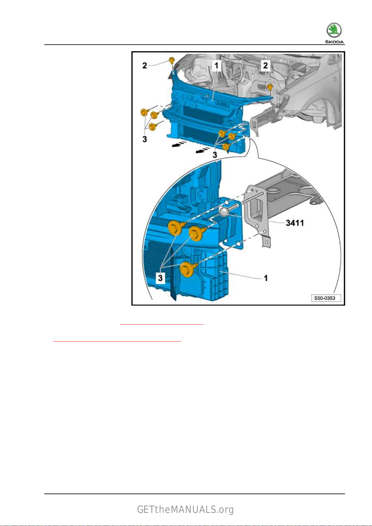
– Removing front bumper ⇒ “1.1.2 Removing”, page 132 .
– Pull off the control cable from the lock carrier
⇒ “1.7 Separating the Bowden cable”, page 28 .
– Remove the screws -3- at the left and right frame side rails.
– Install the guide bars - T30092 (3411)- on the left and right
frame side rails.
– Remove top screws - 2 -.
– The lock carrier -1- can be pulled on the guide bars - T30092
(3411)- by approx. 10 cm forwards
-arrows-.
1. Front body 3
Page 12

Rapid NH 2014 ➤ , Rapid Spaceback 2014 ➤
GETtheMANUALS.org
Body Work - Edition 10.2018
1.3.1 Reinstallation
– Install screws -2- and -3-.
– Take
– Tightening torque of screws (Pos. 2) is 20 Nm.
– Tightening torque of screws (Pos. 3) is 30 Nm.
– Further installation occurs in reverse order.
Hoses and lines must not be pinched.
the mean of the lock carrier with component parts -1- at
the frame side rails and between the wings ⇒ Body Repairs;
Rep. gr. 00 ; technical data; body gaps; front body .
Note
1.4 Removing and installing lock carrier with component parts
Removing
4 Rep. gr.50 - Body - front
Page 13

Rapid NH 2014 ➤ , Rapid Spaceback 2014 ➤
GETtheMANUALS.org
Body Work - Edition 10.2018
– Bring to service position ⇒ “1.3 Service position ”, page 2 .
– Separate electrical plug connections.
– Drain the coolant and separate the coolant line ⇒ Engine
cooling; Rep. gr. 19 .
– Separate the lines for the condenser ⇒ Heating and air con‐
ditioning system; Rep. gr. 87 .
– Remove the guide bars - T30092 (3411)- at the left and right
frame side rails - 2 - with the help of a second mechanic and
remove the lock carrier with component parts
WARNING
- 1 -.
If the cables of the air-conditioning system and/or the coolant
are separated, the drive unit must no longer be started.
Note
♦
The condenser and hydraulic oil cooler must not be tied up to the cables.
♦
The condenser and hydraulic lines must not be kinked.
1. Front body 5
Page 14

Installing
GETtheMANUALS.org
Rapid NH 2014 ➤ , Rapid Spaceback 2014 ➤
Body Work - Edition 10.2018
– Position the lock carrier - 1 - on the frame side rails - 2 -.
– Install the left and right guide bars - T30092 (3411)- .
– Resetting service position ⇒ “1.3.1 Reinstallation”, page 4 .
– Further installation occurs in reverse order.
• Make sure that the plug connections and the hose connections
are correctly mounted during assembly.
– Take the mean of the lock carrier at the frame side rails and
between the wings ⇒ Body Repairs; Rep. gr. 00 ; technical
data; body gaps; front body .
6 Rep. gr.50 - Body - front
Page 15

1.5 Front wing
GETtheMANUALS.org
1.5.1 Summary of components
1 - Wing
❑
Removing
⇒ “1.5.2 Removing front
wing”, page 8 .
❑
Installing
⇒ “1.5.3 Installing the
front wing”, page 10 .
2 - Screw
❑
Tightening torque - 4
Nm.
3 - Screw
❑ Tightening torque - 8
Nm.
4 - Wing support
❑ Removing and installing
⇒ “1.6 Removing and in‐
stalling the wing sup‐
port”, page 11 .
5 - Interior trim
❑ Removing
⇒ “1.5.2 Removing front
wing”, page 8 .
6 - Foam part
❑
Inserted between the
wing and the front top
frame side rail.
7 - Damping of interior trim
and installing
Rapid NH 2014 ➤ , Rapid Spaceback 2014 ➤
Body Work - Edition 10.2018
1. Front body 7
Page 16
Rapid NH 2014 ➤ , Rapid Spaceback 2014 ➤
GETtheMANUALS.org
Body Work - Edition 10.2018
1.5.2 Removing front wing
– Remove front wheelhouse liner
⇒ “1.1 Front wheelhouse liner”, page 158 .
– Remove side turn signal ⇒ Electrical System; Rep. gr. 94 .
– On
vehicles fitted with a damping, first of all remove the damp‐
ing.
– Loosen catch hook -3- and clip -2-.
– Slightly pull the interior trim -1- in the lower area forwards
-arrow b- and then guide it out towards the bottom -arrow a-.
8 Rep. gr.50 - Body - front
Page 17

Rapid NH 2014 ➤ , Rapid Spaceback 2014 ➤
GETtheMANUALS.org
Body Work - Edition 10.2018
Carry out the following tasks
– Removing front bumper ⇒ “1.1.2 Removing”, page 132 .
– Pull out the foam part between the wing and the frame side
rail.
– Pull the damping of the interior trim out of the wheelhouse.
– Unscrew screw -2-.
– Unscrew screws -3-.
– For this step the bumper holder -4- must not be removed.
– The rear screw -2- can be reached when the front flap is
closed.
tect it from damage.
– Carefully remove the wing - 1 -.
Cover the front flap with adhesive tape in order to pro‐
1. Front body 9
Page 18

Rapid NH 2014 ➤ , Rapid Spaceback 2014 ➤
GETtheMANUALS.org
Body Work - Edition 10.2018
1.5.3 Installing the front wing
Carry out the following tasks
– The installation of the wing - 1 - occurs in the reverse order.
– Tightening torque of screw -2- (4 Nm).
– Tightening torque of screws -3- (8 Nm).
– Observe
pairs; Rep. gr. 00 ; technical data; body gaps; front body .
The wing support must be loosened when the fitting is carried out
⇒ “1.6 Removing and installing the wing support”, page 11 .
Install the wing -1- free of stress.
the parallelism and the correct gap sizes ⇒ Body Re‐
Note
10 Rep. gr.50 - Body - front
Page 19

Rapid NH 2014 ➤ , Rapid Spaceback 2014 ➤
GETtheMANUALS.org
1.6 Removing and installing the wing support
Body Work - Edition 10.2018
Removing
– Remove front bumper cover ⇒ “1.1.2 Removing”, page 132 .
– Release screws - 3 - and remove wing support - 2 -.
Installing
– Install wing support - 2 -.
– Adapt wing support with the wing -1- to the front flap and
bumper ⇒ Body Repairs; Rep. gr. 00 ; Technical data; body
gaps; front body .
– Tightening torque of screws -3- (8 Nm).
1. Front body 11
Page 20

Rapid NH 2014 ➤ , Rapid Spaceback 2014 ➤
GETtheMANUALS.org
Body Work - Edition 10.2018
1.7 Bulkhead plenum chamber
1.7.1 Summary of components
1 - Bulkhead plenum chamber
Removing
–
Remove the plenum
chamber cover
⇒ “1.8.2 Removing”,
page 14 .
–
Remove engine air duct
(depending on engine).
– Remove engine control
unit and engine control
module holder.
– Remove noise insula‐
tion.
– Unscrew screws -2-.
– Remove the bulkhead
plenum chamber -1- up‐
wards and out of the ple‐
num chamber -4-.
Installing
– The installation occurs
in reverse order.
2 - Screw
❑ Tightening torque - 8
Nm.
3 - Plenum chamber
4 - Seal
Note
Ensure that the seal is correctly
seated when installing the bulkhead
plenum chamber.
5 - Damping
❑ Attached to the bulkhead plenum chamber with clamping plates.
6 - Circlip
❑ For attaching the damping on the bulkhead plenum chamber.
12 Rep. gr.50 - Body - front
Page 21

1.8 Plenum chamber cover
GETtheMANUALS.org
1.8.1 Summary of components
1 - Additional cover
❑
Fitted on the wing web
plate.
2 - Plenum chamber cover
❑ Removing
⇒ “1.8.2 Removing”,
page 14 .
❑
Installing
⇒ “1.8.3 Installing”,
page 15 .
3 - Additional cover
❑
Fitted on the wing web
plate.
4 - Moulded foam part
5 - Seal
6 - Moulded foam part
Rapid NH 2014 ➤ , Rapid Spaceback 2014 ➤
Body Work - Edition 10.2018
1. Front body 13
Page 22

Rapid NH 2014 ➤ , Rapid Spaceback 2014 ➤
GETtheMANUALS.org
Body Work - Edition 10.2018
1.8.2 Removing
– Remove wiper arms ⇒ Electrical System; Rep. gr. 92 .
– Detach the seal -2- along the entire length of the plenum
chamber cover -1-.
Caution
The plenum chamber cover must not be levered off with a lever
tool (screwdriver, wedge). The washer is damaged and can
subsequently tear.
– Lift up the plenum chamber cover -1- on the edge of the wind‐
screen by hand.
– Pull the plenum chamber cover -1- starting at the edge of the
windscreen -6- towards the top and out of the fitting section
-5-.
– Remove plenum chamber cover -1- from vehicle.
14 Rep. gr.50 - Body - front
Page 23

Rapid NH 2014 ➤ , Rapid Spaceback 2014 ➤
GETtheMANUALS.org
1.8.3 Installing
Caution
Breaking open the plenum chamber cover -1- in the fitting sec‐
tion -5- of the windscreen -6- can lead to cracks in the wind‐
screen.
Body Work - Edition 10.2018
Note
♦
An inlay is installed in the fitting section on new windscreens. This inlay must be removed before installing
the plenum chamber cover.
♦
The plenum chamber cover must be slightly pressed into the fitting section by hand, but on no account knock
or press in using a tool.
Carry out the following tasks
– Wet the fitting section -5- with soapy water so that the plenum
chamber covers -1- can be pressed in more easily.
1. Front body 15
Page 24

Rapid NH 2014 ➤ , Rapid Spaceback 2014 ➤
GETtheMANUALS.org
Body Work - Edition 10.2018
– Place the plenum chamber covers -1- onto the fitting section
-5- and clip it, starting from the centre, into the fitting section
-5- with slight pressure.
– Fit the seal - 2 - onto the plenum chamber cover - 1 -.
– Installing windscreen wipers ⇒ Electrical System; Rep. gr.
92 .
1.9 Noise insulation
1.9.1 Summary of components
Note
Depending on the model version, slight differences must be taken into consideration when removing and in‐
stalling.
1 - Noise insulation
Removing
– Remove the screws -2-
and push out the noise
insulation towards the
rear.
2 - Screw
❑ Tightening torque - 2
Nm.
3 - Shock absorber cover
16 Rep. gr.50 - Body - front
Page 25
1.10 V-ribbed belt protection
GETtheMANUALS.org
1.10.1 Summary of components
1 - V-ribbed belt protection
Removing
–
Unscrew screws -2-.
Installing
– The installation occurs
in reverse order.
2 - Screw
❑ Tightening torque - 2
Nm.
3 - Snap nut
Rapid NH 2014 ➤ , Rapid Spaceback 2014 ➤
Body Work - Edition 10.2018
1. Front body 17
Page 26

Rapid NH 2014 ➤ , Rapid Spaceback 2014 ➤
GETtheMANUALS.org
Body Work - Edition 10.2018
1.11 Underfloor trim panel
1.11.1 Summary of components
1 - Floor covering
Removing
–
Unscrew nuts - 2 -.
Installing
– The installation occurs
in reverse order.
2 - Nut
❑ Tightening torque - 2
Nm.
3 - Threaded bores
❑ Welded to the floor pan‐
el.
18 Rep. gr.50 - Body - front
Page 27

1.12 Tunnel bridge
GETtheMANUALS.org
1.12.1 Summary of components
1 - Tunnel bridge
Removing
–
Remove underbody
panels
⇒ “1.11 Underfloor trim
panel”, page 18 .
–
Unscrew nuts - 2 -.
Installing
– The installation occurs
in reverse order.
2 - Nut
❑ Tightening torque - 20
Nm.
3 - Threaded bores
❑ Welded to the floor pan‐
el.
Rapid NH 2014 ➤ , Rapid Spaceback 2014 ➤
Body Work - Edition 10.2018
1. Front body 19
Page 28

Rapid NH 2014 ➤ , Rapid Spaceback 2014 ➤
GETtheMANUALS.org
Body Work - Edition 10.2018
55 – Bonnet, rear lid
1 Front flap
1.1 Summary of components
1 - Front flap
❑ Removing and installing
⇒ “1.2.1 Removing”,
page 21 .
❑ Setting
⇒ “1.10 Adjusting the
bonnet”, page 32 .
2 - Plug
3 - Adjusting buffer
4 - Locking clamp
5 - Damping
Removing
– Unclip all the clips for
the damping in se‐
quence.
– Remove the damping
from the bonnet.
Installing
– The installation occurs
in reverse order.
6 - Bump stop
7 - Adjusting buffer
8 - Plug
9 - Hinge
❑ Removing and installing
⇒ “1.3 Removing and in‐
stalling the hinge for the
front flap”, page 23 .
❑ Setting
⇒ “1.10 Adjusting the bonnet”, page 32 .
10 - Spray nozzles
❑ Removing and installing ⇒ Electrical System; Rep. gr. 92 .
11 - Support bar
❑ Removing and installing ⇒ “1.4 Removing and installing the support bar”, page 24 .
12 - Flap lock bonnet
❑ Removing and installing ⇒ “1.6 Removing and installing front flap lock ”, page 25 .
13 - Screw
❑ Tightening torque - 20 Nm.
14 - Nut
❑ Tightening torque - 20 Nm.
20 Rep. gr.55 - Bonnet, rear lid
Volkswagen Technical Site:
http://vwts.ru http://vwts.info
Page 29

Rapid NH 2014 ➤ , Rapid Spaceback 2014 ➤
GETtheMANUALS.org
15 - Retaining clip
1.2 Removing and installing the bonnet
1.2.1 Removing
Body Work - Edition 10.2018
– Remove
– Unclip the cable -4- from the front flap -1-.
– Pull the cable -4- out of the opening of the front flap -1-.
– Slacken the nuts -3- on the left and right at the hinge -2- (do
not unscrew).
Carry out further removal only with the assistance of a second
mechanic.
– Remove support bar -6- from the front flap.
– Only now unscrew the nuts -3- and lift the front flap -1- out of
the hinges -2-.
spray nozzles -5- ⇒ Electrical System; Rep. gr. 92 .
1. Front flap 21
Page 30

Rapid NH 2014 ➤ , Rapid Spaceback 2014 ➤
GETtheMANUALS.org
Body Work - Edition 10.2018
1.2.2 Installing
Installing
– The installation occurs in reverse order.
– Adjust front flap -1-
⇒ “1.10 Adjusting the bonnet”, page 32 .
22 Rep. gr.55 - Bonnet, rear lid
Page 31

Rapid NH 2014 ➤ , Rapid Spaceback 2014 ➤
GETtheMANUALS.org
1.3 Removing and installing the hinge for the front flap
1.3.1 Removing
Body Work - Edition 10.2018
– Remove front flap -3- ⇒ “1.2.1 Removing”, page 21 .
– Remove screws -2- (20 Nm).
– Remove hinge - 1 -.
1.3.2 Installing
– The installation occurs in reverse order.
1. Front flap 23
Page 32

Rapid NH 2014 ➤ , Rapid Spaceback 2014 ➤
GETtheMANUALS.org
Body Work - Edition 10.2018
1.4 Removing and installing the support bar
Removing
– Support the bonnet.
– Swivel
port bar out of the rubber grommet - 2 -.
Installing
– Push the support bar -1- into the rubber grommet (Pos.2)
-arrow a-.
– Swivel the support bar towards the lock carrier -arrow b-.
– Check the bracket -3- for damage, replace it if necessary.
the support bar - 1 - towards the front and pull the sup‐
24 Rep. gr.55 - Bonnet, rear lid
Page 33

Rapid NH 2014 ➤ , Rapid Spaceback 2014 ➤
GETtheMANUALS.org
Body Work - Edition 10.2018
1.5 Lock and unlock components of front flap - Summary of components
1 - Locking clamp
❑
Removing
⇒ “1.8 Removing and in‐
stalling the locking
clamp”, page 29 .
❑
Setting
⇒ “1.10.2 Adjusting the
locking clamp”,
page 34 .
2 - Release handle
❑ Removing
⇒ “1.9.2 Removing and
installing”, page 31 .
3 - Bowden cable
❑
From the Bowden cable
coupling to the operat‐
ing lever
⇒ “1.9 Removing and in‐
stalling the operating
lever”, page 30 .
4 - Retaining clip
5 - Bowden cable
6 - Bowden wire coupling
❑
The Bowden cable cou‐
pling is located above
the headlight on the
driver's side.
❑ Separate
⇒ “1.7 Separating the
Bowden cable”,
page 28 .
7 - Bowden cable
❑
From the front flap lock
to the Bowden cable
coupling.
❑ Clipped into the Bowden cable coupling.
8 - Flap lock bonnet
❑ Remove and install front flap lock
❑
Setting
and installing
⇒ “1.6 Removing and installing front flap lock ”, page 25 .
⇒ “1.10.1 Adjusting the flap lock”, page 33 .
1.6 Removing and installing front flap lock
Note
Depending on the model version, slight differences must be taken
into consideration when removing and installing the front flap lock.
1. Front flap 25
Page 34

Rapid NH 2014 ➤ , Rapid Spaceback 2014 ➤
GETtheMANUALS.org
Body Work - Edition 10.2018
1.6.1 Removing
Note
The Bowden cable -2- is not separated from the front flap lock.
– Open front flap.
– Separate
⇒ “1.7 Separating the Bowden cable”, page 28 .
– Depending on the additional equipment, disconnect the plug
connection for the contact switch of the engine hood.
– Release the screws - 4 - (12 Nm) and remove the flap lock
- 1 - in - direction of arrow a - from the lock carrier.
Depending on the additional equipment, remove and install the contact switch for the engine hood at the flap
lock ⇒ Electrical System; Rep. gr. 96 .
the Bowden cable -2- in the Bowden cable coupling
Note
26 Rep. gr.55 - Bonnet, rear lid
Page 35

1.6.2 Installing
GETtheMANUALS.org
Rapid NH 2014 ➤ , Rapid Spaceback 2014 ➤
Body Work - Edition 10.2018
– Clip the end part - 3 - of the Bowden cable - 2 - into the flap
lock (if it was removed) - arrow a -.
– Push the flap lock -1- into the lock carrier -arrow b-.
– Depending
nection for the contact switch of the engine hood.
– Tightening torque of screws -4- (12 Nm).
– Install the Bowden cable -2- in the Bowden cable coupling
⇒ “1.7 Separating the Bowden cable”, page 28 .
– Adjust flap lock ⇒ “1.10.1 Adjusting the flap lock”, page 33 .
• Before closing the front flap, carry out a functional test of the
operating lever and the Bowden cable.
on the additional equipment, connect the plug con‐
1. Front flap 27
Page 36

Rapid NH 2014 ➤ , Rapid Spaceback 2014 ➤
GETtheMANUALS.org
Body Work - Edition 10.2018
1.7 Separating the Bowden cable
Removing
– Open front flap.
– Unclip the Bowden cable coupling - 2 -, located above the
headlight on the driver's side, out of the lock carrier
-arrow a-.
– Take the Bowden cables -1- and -3- out of the Bowden cable
coupling -2-
– Swivel the Bowden cable -1- about 90° in
-direction of arrow b- and take the Bowden cable
-in direction of arrow c- out of the support of the Bowden cable.
Installing
– The installation occurs in reverse order.
in -arrows a-.
28 Rep. gr.55 - Bonnet, rear lid
Page 37

Rapid NH 2014 ➤ , Rapid Spaceback 2014 ➤
GETtheMANUALS.org
Body Work - Edition 10.2018
Note
♦
When installing the Bowden cable - 3 -, ensure that the grommet - 5 - is correctly secured.
♦
When attaching the Bowden cable - 3 -, pay attention to the mandatory clipping - 4 -.
• Before closing the front flap, carry out a functional test of the
operating lever and the Bowden cable.
1.8 Removing and installing the locking clamp
Removing
– Unscrew screws -3-.
– Remove the locking clamp - 1 - from the front flap - 2 -.
Installing
– Tightening torque of screws -3- (10 Nm).
– Adjust the locking clamp to the flap lock
⇒ “1.10.2 Adjusting the locking clamp”, page 34 .
1. Front flap 29
Page 38

Rapid NH 2014 ➤ , Rapid Spaceback 2014 ➤
GETtheMANUALS.org
Body Work - Edition 10.2018
1.9 Removing and installing the operating lever
1.9.1 Summary of components
1 - Bearing bracket
2 - Bowden cable
Installing
–
Insert the ball of the
Bowden cable into the
bracket -arrow a- and
secure the Bowden ca‐
ble in the bearing brack‐
et -arrow b-.
3 - Expanding nut
4 - Screw
❑ Tightening torque - 2
Nm.
5 - Release handle
❑ Removing and installing
⇒ “1.9.2 Removing and
installing”, page 31 .
30 Rep. gr.55 - Bonnet, rear lid
Page 39

1.9.2 Removing and installing
GETtheMANUALS.org
Rapid NH 2014 ➤ , Rapid Spaceback 2014 ➤
Body Work - Edition 10.2018
Removing
– Tighten the operating lever -1- and unlock the bonnet.
– Fit a small screwdriver into the gap between the operating
lever - 1 - and the retaining clip
– Lever the retaining clip -2- out of the operating lever (Pos. 1)
-arrow- and detach the operating lever from the bearing brack‐
et -3-.
When carrying out further work on the bearing bracket - 3 -, re‐
move the bottom A pillar trim panel - 4 -.
Installing
• The bottom A pillar trim panel -4- is installed.
– Push the retaining clip -2- into the operating lever.
– Press the operating lever - 1 - onto the bearing bracket - 3 -.
- 2 -.
1. Front flap 31
Page 40

Rapid NH 2014 ➤ , Rapid Spaceback 2014 ➤
GETtheMANUALS.org
Body Work - Edition 10.2018
1.10 Adjusting the bonnet
Note
♦
The vehicle must be positioned on the flat ground in order to adjust the bonnet.
♦
The adjusting buffers -2- on the left and right are not used for the adjustment. They have the function to
stabilise or dampen the bonnet.
♦
The bonnet is correctly adjusted if in the closed state it has an overall even gap size, is not positioned too
far outwards or inwards and the contours are aligned.
♦
The bonnet must latch in the flap lock without using increased force.
♦
The nuts are not unscrewed, only slackened.
– Remove locking clamp -1-
⇒ “1.8 Removing and installing the locking clamp”, page 29 .
– The
– Ensure parallelism of gap dimensions ⇒ Body Repairs; Rep.
mean of the front flap can be taken between the wings by
slackening the nuts -6- on the left and right hinges -7-.
gr. 00 ; Technical data; body gaps; front body .
32 Rep. gr.55 - Bonnet, rear lid
Page 41

Rapid NH 2014 ➤ , Rapid Spaceback 2014 ➤
GETtheMANUALS.org
Body Work - Edition 10.2018
Adjusting the adjusting buffer
Note
♦
Install the adjusting buffer - 2 and 3 - on the left and right up to the stop.
♦
Turn the adjusting buffers by 90° if required, in order to pretension the flap.
– After the front flap has been adjusted, the locking clamp - 1 -
can once again be installed and adjusted
⇒ “1.10.2 Adjusting the locking clamp”, page 34 .
– The
– After the flap has been adjusted, the locking clamp has been
– After carrying out adjustment work, perform corrosion protec‐
front flap can be adjusted in the front area to the height of
the wings with the flap lock -5-
⇒ “1.10.1 Adjusting the flap lock”, page 33 .
installed
justing buffers can be turned if required.
tion measures on the hinges -6- and the screws -7- .
and all the connections have been tightened, the ad‐
1.10.1 Adjusting the flap lock
1. Front flap 33
Page 42

Rapid NH 2014 ➤ , Rapid Spaceback 2014 ➤
GETtheMANUALS.org
Body Work - Edition 10.2018
– If the screws -2- are loosened, the front flap lock -1- can be
adjusted to the front flap laterally -arrow a-
-arrow b- ⇒ Body Repairs; Rep. gr. 00 ; body gaps; front body .
– Tightening torque of screws -2- (12 Nm).
and in height
1.10.2 Adjusting the locking clamp
– Release screws - 3 -.
– The locking clamp -1- can now be adjusted in the oversized
holes.
– Tightening torque of screws -3- (10 Nm).
34 Rep. gr.55 - Bonnet, rear lid
Page 43

2 Tailgate
GETtheMANUALS.org
2.1 Summary of components
1 - Screw
❑
Tightening torque - 8
Nm.
2 - Wedge buffer
3 - Tailgate trim panel
❑ Removing and installing
⇒ “4 Tailgate trim pan‐
el”, page 274 .
4 - Tailgate
❑ Removing
⇒ “2.2 Removing and in‐
stalling tailgate”,
page 36 .
❑
Setting
⇒ “2.4 Adjusting tail‐
gate”, page 37 .
5 - Rubber buffer
❑
Setting
⇒ “2.4.2 Adjusting the
rubber buffer”,
page 39 .
6 - Ball pin
–
Tightening torque - 20
Nm.
and installing
Rapid NH 2014 ➤ , Rapid Spaceback 2014 ➤
Body Work - Edition 10.2018
7 - Pressurized gas strut
– Removing and installing
⇒ “2.6 Removing and in‐
stalling pressurized gas
strut of tailgate”,
page 40 .
2. Tailgate 35
Page 44

Rapid NH 2014 ➤ , Rapid Spaceback 2014 ➤
GETtheMANUALS.org
Body Work - Edition 10.2018
2.2 Removing and installing tailgate
2.2.1 Removing
– Remove the tailgate trim panel
⇒ “4 Tailgate trim panel”, page 274 .
– Disconnect
ponents.
– Thread the electrical cables out of the tailgate.
– Slacken the screws - 3 - (10 Nm) on the left and right hinges
but do not yet unscrew.
Carry out further removal only with the assistance of a second
mechanic.
– Only now unscrew the screws - 3 - and remove the tailgate.
– Only if the complete hinge for the tailgate must be removed,
release the nuts - 2 - (20 Nm). In this case the moulded head‐
liner must be unhooked
the plug connections of the existing electrical com‐
36 Rep. gr.55 - Bonnet, rear lid
⇒ “7 Moulded headliner”, page 282 .
Page 45

Rapid NH 2014 ➤ , Rapid Spaceback 2014 ➤
GETtheMANUALS.org
Installing
– The installation occurs in reverse order.
Note
Adjust the tailgate after installing ⇒ “2.4 Adjusting tailgate”, page 37 .
2.3 Removing and installing the locking mechanism
2.3.1 Removing
Body Work - Edition 10.2018
– Unscrew
luggage compartment wall.
Installing
– The installation occurs in reverse order.
– Set the locking mechanism
⇒ “2.4.1 Setting the locking mechanism”, page 39 .
screw -2- and remove the closing wedge -1- from the
2.4 Adjusting tailgate
Note
♦
The vehicle must be standing on its wheels in order to adjust the tailgate.
♦
The flap lock is directly screwed onto the tailgate. It has no elongated holes and therefore it cannot be
adjusted.
♦
The adjusting buffers on the left and right are not used for the adjustment. They have the function to stabilise
or dampen the bonnet.
♦
The bonnet is correctly adjusted if in the closed state it has an overall even gap size, is not positioned too
far outwards or inwards and the contours are aligned.
♦
The tailgate must latch in the flap lock without using increased force.
2. Tailgate 37
Page 46

Rapid NH 2014 ➤ , Rapid Spaceback 2014 ➤
GETtheMANUALS.org
Body Work - Edition 10.2018
Use a setting gauge for setting or checking the gap sizes ⇒ Body
Repairs; Rep. gr. 00 ; Body gaps; rear body .
– The tailgate can be adjusted in the oversized bores of the
hinges horizontally and vertically by slackening the screws
- 3 -.
Tightening torque of screws -3- (10 Nm).
– After carrying out adjustment work, perform corrosion protec‐
tion measures at the hinges and screws.
– Adjust the tailgate on the closing wedge
⇒ “2.4.1 Setting the locking mechanism”, page 39 .
– Adjust the rubber buffer on the left and right
⇒ “2.4.2 Adjusting the rubber buffer”, page 39 .
38 Rep. gr.55 - Bonnet, rear lid
Page 47

Rapid NH 2014 ➤ , Rapid Spaceback 2014 ➤
GETtheMANUALS.org
2.4.1 Setting the locking mechanism
Note
♦
The closing wedge -2- can be moved in the oversized bores
-arrows a- and -arrows b- by loosening the screws - 1 -.
♦
Set the locking mechanism - 2 - in such a way that the recess
of the tailgate lock with the catch engages centrally in the
locking mechanism - 2 -.
– Release screws - 1 -.
– Push the locking mechanism -2- out into the upper position
and tighten the screws -1-.
– Close the tailgate and check the setting.
Tightening torque of screws -1- (20 Nm).
2.4.2 Adjusting the rubber buffer
Body Work - Edition 10.2018
– Adjust
– Remove rubber buffers -2- by approximately 2 mm out of the
– The tailgate -1- must latch in the flap lock without using in‐
2.5 Removing
If the tailgate does not open, the emergency release can be
opened mechanically from the luggage compartment via the lock
cylinder ⇒ Owner's Manual .
the rubber buffer in such a way that no excessive forces
must be used when closing the tailgate -1- and that it engages
in the lock.
tailgate -1-.
creased force.
and installing the tailgate lock
Note
2.5.1 Removing and installing
2. Tailgate 39
Page 48

Rapid NH 2014 ➤ , Rapid Spaceback 2014 ➤
GETtheMANUALS.org
Body Work - Edition 10.2018
Removing
– Remove lock cover - 3 -.
– Disconnect the plug connection from the tailgate lock control
- 1 -.
– Release
the tailgate.
Installing
– The installation occurs in reverse order.
the nuts -2- (21 Nm) and remove the flap lock -1- from
2.6 Removing and installing pressurized
gas strut of tailgate
Removing
– Open tailgate, support and lock it into position.
– Use a screwdriver to raise the locking element - 2 - and pull
the pressurized gas strut - 1 - off the ball stud - 3 -.
Note
If the pressurized gas strut is to be re-used, do not remove the
locking device fully from the ball socket, otherwise it will be dam‐
aged.
– 1 - Pressurized gas strut
– 2 - Locking device
– 3 - Ball stud
Installing
– The installation occurs in reverse order.
40 Rep. gr.55 - Bonnet, rear lid
Page 49

Rapid NH 2014 ➤ , Rapid Spaceback 2014 ➤
GETtheMANUALS.org
2.7 Tailgate seal
2.7.1 Installation instructions
♦ If the seal is re-installed, leak-tightness and tight fit can no
longer be guaranteed.
♦ For this reason, each seal which was completely removed
must be replaced with a so-called “hammer finish seal”.
♦ If the seals were detached partially, press together the sides
of the seal before installing.
2.7.2 Removing and installing tailgate seal
Body Work - Edition 10.2018
Removing
– Pay attention to installation instructions
⇒ “2.7.1 Installation instructions”, page 41 .
– Detach the seal for the tailgate -1- from the body flange.
Installing
– Press the seal -1- evenly onto the body flange.
2. Tailgate 41
Page 50

Rapid NH 2014 ➤ , Rapid Spaceback 2014 ➤
GETtheMANUALS.org
Body Work - Edition 10.2018
3 Fuel tank lid unit
3.1 Fuel-tank lid unit - Summary of components
1 - Locking mechanism
2 - Fuel tank lid unit
❑ Removing
⇒ “3.2 Removing and in‐
stalling fuel tank lid unit”,
page 42 .
3 - Water drain hose
❑ Laid
house and the wheel‐
house liner.
and installing
between the wheel‐
3.2 Removing
and installing fuel tank lid unit
3.2.1 Removing
– First pierce the unit in the upper area with a thin screwdriver
- 4 - or a nail - 1 - - 2 - in the - direction of arrow a - .
– Lightly ress the screwdriver in the -direction of arrow b - the
catches - 5 - will be unlocked as a result.
– After unlocking the upper latches, slightly swivel the unit out
of the side panel. The lower catches should then extend up‐
wards.
upper area.
– Remove the rubber grommet from the fuel filler neck.
– Remove the fuel tank lid unit from the side section.
If the lower area can not be removed, proceed as in the
3.2.2 Installing
– The installation occurs in reverse order.
42 Rep. gr.55 - Bonnet, rear lid
Page 51

Rapid NH 2014 ➤ , Rapid Spaceback 2014 ➤
GETtheMANUALS.org
Body Work - Edition 10.2018
Note
If the latches for the fuel tank lid unit are damaged, use a new
part.
3.3 Fuel-tank lid unit (Spacebook)- Summary of components
1 - Fuel tank lid
2 - Fuel tank lid unit
Removing and installing
⇒ “4 Removing and installing
fuel tank lid unit (Spacebook)”,
page 44 .
3 - Water drain hose
4 - Locking mechanism
5 - Fuel filler neck
6 - Side section
3. Fuel tank lid unit 43
Page 52

Rapid NH 2014 ➤ , Rapid Spaceback 2014 ➤
GETtheMANUALS.org
Body Work - Edition 10.2018
4 Removing and installing fuel tank lid unit (Spacebook)
Removing
– Unlock
panel- 2 -, in the same way as in the Rapid model
⇒ “3.2 Removing and installing fuel tank lid unit”, page 42 .
– Remove fuel tank lid unit - 1 - outwards.
Installing
– Perform the installation by pressing in the fuel tank lid unit in
the lateral part. Latch the fuel tank lid unit for the correct po‐
sition until it audibly clicks into place.
If the latches for the fuel tank lid unit are damaged, use a new part.
the catches - arrows -, which are clipped onto the side
Note
44 Rep. gr.55 - Bonnet, rear lid
Page 53

Rapid NH 2014 ➤ , Rapid Spaceback 2014 ➤
GETtheMANUALS.org
Body Work - Edition 10.2018
57 – Front doors, door components, central locking
1 Front door
1.1 Assembly overview - door hanger
Note
Always replace the screws for the door hinges after the removal.
1 - Door
❑ Removing and installing
⇒ “1.2 Removing and in‐
stalling the door”,
page 47 .
❑ Setting
⇒ “1.3 Door adjust‐
ment”, page 49 .
2 - Multi-point socket head bolt
❑ 32 Nm.
❑ Always replace the
screws after the remov‐
al.
3 - Door hinge
❑ The top part is connec‐
ted to the bottom part of
the hinge by the screw
- 4 -.
4 - Screw
❑ This screw must be un‐
screwed in order to re‐
move the door from the
hinge.
❑ 23 Nm.
5 - Multi-point socket head bolt
❑ Installed from the inside
of the vehicle.
❑ Remove bottom A-pillar
trim panel.
❑ 32 Nm.
❑ Always replace the
screws after the remov‐
al.
6 - Door hinge
❑ The bottom part is connected to the top part of the hinge by the screw -4-.
7 - Multi-point socket head bolt
❑ 32 Nm.
❑ Always replace the screws after the removal.
8 - Screw
❑ 32 Nm.
❑ 30 Nm - only for the assembly plant in Russia.
Volkswagen Technical Site:
http://vwts.ru http://vwts.info
1. Front door 45
Page 54

Rapid NH 2014 ➤ , Rapid Spaceback 2014 ➤
GETtheMANUALS.org
Body Work - Edition 10.2018
❑ This screw must be unscrewed in order to remove the door.
9 - Door retaining strap
10 - Screw
❑
9 Nm.
11 - Multi-point socket head bolt
❑ Installed from the inside of the vehicle.
❑ Remove and install the dash panel for loosening or tightening the screw on the driver's side
⇒ “1.1 Removing and installing the dash panel”, page 244 .
❑
Remove and install the dash panel for loosening or tightening the screw on the front passenger side
⇒ “1.1 Removing and installing the dash panel”, page 244 .
❑
32 Nm.
❑ Always replace the screws after the removal.
12 - Door hinge
❑ The bottom part is connected to the top part of the hinge by the screw -16-.
13 - Multi-point socket head bolt
❑ 32 Nm.
❑ Always replace the screws after the removal.
14 - Multi-point socket head bolt
❑ 32 Nm.
❑ Always replace the screws after the removal.
15 - Door hinge
❑ The top part is connected to the bottom part of the hinge by the screw - 12 -.
16 - Screw
❑ 23 Nm.
❑ This screw must be screwed down in order to remove the door from the hinge bolt.
46 Rep. gr.57 - Front doors, door components, central locking
Page 55

1.2 Removing and installing the door
GETtheMANUALS.org
1.2.1 Removing
Rapid NH 2014 ➤ , Rapid Spaceback 2014 ➤
Body Work - Edition 10.2018
– Release
detach it from the A pillar.
– Swivel the release lever -3- downwards -arrow b- and discon‐
nect the el. plug connection -4- from the connector station.
– Slacken the screws -7- at the hinges -arrows d-.
– Remove the screws -5- for the door retaining strap -6-.
– Pull the door -1- upwards -arrow e- and out of the hinges -8-.
the bellows -2- by pressing on the catch -arrow a- and
1. Front door 47
Page 56

Rapid NH 2014 ➤ , Rapid Spaceback 2014 ➤
GETtheMANUALS.org
Body Work - Edition 10.2018
1.2.2 Installing
Installing
– The installation occurs in reverse order.
– Tightening torques of screws
⇒ “1.1 Assembly overview - door hanger ”, page 45 .
– Observe
gr. 00 ; technical data; body gaps; front body .
the gap sizes of the front door ⇒ Body Repairs; Rep.
48 Rep. gr.57 - Front doors, door components, central locking
Page 57

Rapid NH 2014 ➤ , Rapid Spaceback 2014 ➤
GETtheMANUALS.org
Body Work - Edition 10.2018
1.3 Door adjustment
Note
♦
The vehicle must be standing on its wheels in order to adjust the door.
♦
The door is correctly adjusted if in the closed state it has an overall even gap size, is not positioned too far
outwards or inwards and the contours are aligned.
♦
For checking the gap sizes: ⇒ Body Repairs; Rep. gr. 00 ; Technical data; body gaps; front body .
♦
After carrying out adjustment work, perform corrosion protection measures at the screws and hinges.
Setting the gap sizes
In order to correctly set the gap sizes, the screws
-2, 5, 7, and 8- must be slackened at the A pillar.
– The bottom A pillar trim panel must be removed for slackening
the screw -5-
⇒ “3.2 Removing and installing bottom trim panel of pillar A on
the driver's side”, page 264 .
1. Front door 49
Page 58

Rapid NH 2014 ➤ , Rapid Spaceback 2014 ➤
GETtheMANUALS.org
Body Work - Edition 10.2018
– The dash panel must be removed on the driver's side for
slackening the screw
⇒ “1.1 Removing and installing the dash panel”, page 244 .
– The glove compartment must be removed on the front pas‐
senger side for slackening the screw
⇒ “1.2 Removing and installing the glove compartment”, page
249 .
Setting the gap sizes
The screws -3 and 9- must be released for correctly setting the
flushness.
Note
Other measures, such as aligning the doors towards the top are ineffective. The door will drop again at the
following overpressures.
Adjusting the locking clamp
⇒ “1.3.1 Adjusting the locking clamp”, page 50 .
- 7 -
- 7 -
1.3.1 Adjusting the locking clamp
50 Rep. gr.57 - Front doors, door components, central locking
Page 59

Rapid NH 2014 ➤ , Rapid Spaceback 2014 ➤
GETtheMANUALS.org
Body Work - Edition 10.2018
Note
♦
The arc outside the threaded plate must be firmly welded to the pillar. The lands to the threaded plate are
malleable.
♦
To adjust the locking clamp -2- once the screws -3- are loosened, increased force must be applied.
Note
♦
When closing the door it must lock completely without using
additional force and must have no play.
♦
When adjusting the locking clamp, the door must not be press‐
ed upwards or downwards.
The locking clamp is used for adjusting the following:
• If the front door adjustment is not flush with the rear door or
the side part.
Carry out the following tasks
– Slacken the locking clamp -1- by loosening the screws -2- at
the B pillar.
– Adjust the door with the locking clamp -2- in such a way that
the front door when in the closed state is flush with the rear
door (wind noise).
– Tighten screws - 2 - of locking clamp - 1 -.
Tightening torque of screws -2- (20 Nm).
1. Front door 51
Page 60

Rapid NH 2014 ➤ , Rapid Spaceback 2014 ➤
GETtheMANUALS.org
Body Work - Edition 10.2018
2 Door internal parts
2.1 Front door - Summary of components
1 - Door
❑ Removing
⇒ “1.2.1 Removing”,
page 47 .
❑
Setting
⇒ “1.3 Door adjust‐
ment”, page 49 .
2 - Clamp
❑ Removing
⇒ “2.9 Removing and in‐
stalling bearing brack‐
et”, page 67 .
3 - Cover for bearing bracket
4 - Cap of lock cylinder
❑ Removing
⇒ “2.4 Removing and in‐
stalling cap for lock cyl‐
inder”, page 57 .
5 - Supporting plate
6 - Outer door handle
❑ Removing
⇒ “2.7 Removing and in‐
stalling the door han‐
dle”, page 63 .
7 - Lock cylinder
❑ Removing
⇒ “2.5 Removing and in‐
stalling lock cylinder”,
page 57 .
8 - External window channel
strip
❑ Removing
⇒ “2.16 Removing and
installing the outer win‐
dow channel strip”, page 81 .
9 - Adhesive pad
10 - Screw
❑
Tightening torque - 2.2 Nm.
11 - Screw
❑ Tightening torque - 20 Nm.
12 - Cap
❑ Removing and installing
13 - Outside door seal
❑
Removing and installing
14 - Loudspeaker
and installing
and installing
and installing
and installing
and installing
and installing
⇒ “2.2 Removing and installing the door cover”, page 53 .
⇒ “2.18 Removing and installing the outside door seal”, page 84 .
15 - Cap
❑
Self-adhesive.
52 Rep. gr.57 - Front doors, door components, central locking
Page 61

Rapid NH 2014 ➤ , Rapid Spaceback 2014 ➤
GETtheMANUALS.org
❑ If a speaker was not installed.
16 - Nut
❑
Tightening torque - 6 Nm.
17 - Riveted nuts
18 - Inner window channel strip
❑ Removing and installing
⇒ “2.15 Removing and installing the inner window channel strip”, page 80 .
2.2 Removing and installing the door cover
2.2.1 Removing
Body Work - Edition 10.2018
– Remove front door trim panel
⇒ “2.1 Removing and installing the front door trim panel”, page
257 .
– Lift off the cover -1- in the bottom area.
– Pull the cover - 1 - downwards and remove it from the door
- 5 -.
2. Door internal parts 53
Page 62

Rapid NH 2014 ➤ , Rapid Spaceback 2014 ➤
GETtheMANUALS.org
Body Work - Edition 10.2018
Note
♦
If the following operations are necessary, pull the Bowden cable -2- with the grommet -4- out of the cover
-1-.
♦
The cables are slackened in the holders -3-.
Installing
– The installation occurs in reverse order.
2.2.2 Removing and installing the door retaining strap
Removing
– Remove the loudspeaker.
– Remove the screw - 2 - at the A pillar.
– Remove the screws -3- and take out the door retaining strap
-1- through the opening after the loudspeaker.
Installing
– Push
the door retaining strap through the opening for the loud‐
speaker.
54 Rep. gr.57 - Front doors, door components, central locking
Page 63

Rapid NH 2014 ➤ , Rapid Spaceback 2014 ➤
GETtheMANUALS.org
– Install screws - 3 -, tightening torque
⇒ “1.1 Assembly overview - door hanger ”, page 45 .
– Install screws - 2 -, tightening torque
⇒ “1.1 Assembly overview - door hanger ”, page 45 .
– Install loudspeaker.
2.2.3 Removing and installing the locking clamp
Removing
– Release screws - 2 - and remove locking clamp - 1 -.
Installing
– Position locking clamp -1- on the B-pillar -3- and tighten the
screws -2-, tightening torque - 20 Nm.
– Adjusting the locking clamp
⇒ “1.3.1 Adjusting the locking clamp”, page 50 .
Body Work - Edition 10.2018
2.3 Door handle and door lock - Summary of components
2. Door internal parts 55
Page 64

Rapid NH 2014 ➤ , Rapid Spaceback 2014 ➤
GETtheMANUALS.org
Body Work - Edition 10.2018
1 - Door lock
❑ Removing
⇒ “2.8 Removing and in‐
stalling the door lock”,
page 65 .
2 - Screw
❑
For lock cylinder.
❑ Tightening torque - 3.5
Nm.
3 - Clamp
❑ Removing and installing
⇒ “2.9 Removing and in‐
stalling bearing brack‐
et”, page 67 .
4 - Lock cylinder
❑ Removing
⇒ “2.5 Removing and in‐
stalling lock cylinder”,
page 57 .
❑ A
lock cylinder is located
only on the driver's door.
5 - Washer
6 - Cap
❑ Remove and install with
lock cylinder
⇒ “2.4 Removing and in‐
stalling cap for lock cyl‐
inder”, page 57 .
❑
Remove and install
without lock cylinder
⇒ “2.6 Removing and in‐
stalling cap (without lock
cylinder) ”, page 60 .
7 - Door handle
❑
Removing and installing
8 - Screw
❑
Tightening torque - 1.5 Nm.
❑ The bearing bracket is released from the door by loosening the screw.
9 - Control cable
❑ From door lock to bearing bracket.
10 - Control cable
❑ From inner door control to lock release.
❑ With grommet for feeding through at the cover.
11 - Screw
❑ Tightening torque - 20 Nm.
12 - Cap
and installing
and installing
⇒ “2.7 Removing and installing the door handle”, page 63 .
56 Rep. gr.57 - Front doors, door components, central locking
Page 65

Rapid NH 2014 ➤ , Rapid Spaceback 2014 ➤
GETtheMANUALS.org
2.4 Removing and installing cap for lock cyl‐
inder
2.4.1 Removing
Note
When removing the cap for the lock cylinder, do not turn or lever
the screwdriver.
Carry out the following tasks
– Detach door handle.
– Press a small screwdriver -3- slightly -arrow a- into the opening
on the bottom side of the cap for the lock cylinder.
– Slightly pull off the cap of the lock cylinder -1- , together with
the screwdriver, at the bottom side from the door -arrow b-.
– Slide the cap upwards from the lock cylinder.
Body Work - Edition 10.2018
2.4.2 Installing
Carry out the following tasks
– Remove door handle - 1 -.
– Place the cap of the lock cylinder -2- slightly angled from the
top -arrow a- onto the lock cylinder.
– Press the cap of the lock cylinder -2- onto the door -arrow b-,
until the cap with the lock cylinder locks into position.
2.5 Removing and installing lock cylinder
Note
A lock cylinder is installed only on the driver's door.
2. Door internal parts 57
Page 66

Rapid NH 2014 ➤ , Rapid Spaceback 2014 ➤
GETtheMANUALS.org
Body Work - Edition 10.2018
2.5.1 Removing
• The cap for the lock cylinder is removed
⇒ “2.4 Removing and installing cap for lock cylinder”,
page 57 .
– Lift off the covers -4 and 6-.
– Unscrew screw -5-.
– Remove
cylinder.
– Remove door handle - 2 -.
– Pull the lock cylinder housing -1- out of the bearing bracket
-3- at a right angle -arrow b- to the door.
the screw until it stops -7- so that it exposes the lock
58 Rep. gr.57 - Front doors, door components, central locking
Page 67

2.5.2 Installing
GETtheMANUALS.org
Rapid NH 2014 ➤ , Rapid Spaceback 2014 ➤
Body Work - Edition 10.2018
– Remove door handle -2- -arrow a-.
– Fit the lock cylinder housing -1- at a right angle -arrow b- into
the bearing bracket -3– Screw the screws -5 and 7- into the bearing bracket.
– Tightening torque of screws -5 and 7- (3.5 Nm).
Note
During the assembly the lock cylinder housing must be pressed against the outer door panel.
– Further installation occurs in reverse order.
• Then it is absolutely necessary to perform a functional check
when the door is opened.
.
2. Door internal parts 59
Page 68

Rapid NH 2014 ➤ , Rapid Spaceback 2014 ➤
GETtheMANUALS.org
Body Work - Edition 10.2018
2.6 Removing and installing cap (without lock cylinder)
2.6.1 Removing
– Remove the plugs -2- of the rear openings.
– Guide
– Pull the assembly tool - T10389- as far towards the rear
the assembly tool - T10389- by approx. 55 mm into the
door behind the lock hooks -3- of the bearing bracket.
-arrow-, until the hook unlocks.
60 Rep. gr.57 - Front doors, door components, central locking
Page 69

Rapid NH 2014 ➤ , Rapid Spaceback 2014 ➤
GETtheMANUALS.org
– Detach the door handle -2- in -direction of arrow a- from the
door.
– Pull the cap - 1 - out of the bearing bracket -arrow b-.
2.6.2 Installing
– Detach the door handle -2- in -direction of arrow a- from the
door.
– Push the cap -1- into the bearing bracket -arrow b-.
Body Work - Edition 10.2018
2. Door internal parts 61
Page 70

Rapid NH 2014 ➤ , Rapid Spaceback 2014 ➤
GETtheMANUALS.org
Body Work - Edition 10.2018
– Guide the screwdriver -4- at the lock hook -3- of the bearing
bracket.
– Press the cap -1- on the door.
– Press in the screwdriver -arrow- until the hook locks.
– Attach plug -5-.
62 Rep. gr.57 - Front doors, door components, central locking
Page 71

Rapid NH 2014 ➤ , Rapid Spaceback 2014 ➤
GETtheMANUALS.org
2.7 Removing and installing the door handle
2.7.1 Removing
Body Work - Edition 10.2018
– Remove the lock cylinder
⇒ “2.5 Removing and installing lock cylinder”, page 57 or the
cap
⇒ “2.6 Removing and installing cap (without lock cylinder) ”,
page 60 .
– Pull the door handle -1- slightly towards the rear -arrow a- out
of the support of the bearing bracket.
– Swivel the door handle in -direction of arrow b-.
– Remove the door handle at a right angle -arrow a- out of the
bearing bracket -2-.
Volkswagen Technical Site:
http://vwts.ru http://vwts.info
2. Door internal parts 63
Page 72

Rapid NH 2014 ➤ , Rapid Spaceback 2014 ➤
GETtheMANUALS.org
Body Work - Edition 10.2018
2.7.2 Installing
– Fit
the door handle -1- at a right angle -arrow b- into the bearing
bracket.
– Swivel the door handle -1- into the door -arrow b-.
– Forcefully press the door handle forwards -arrow c- into the
support of the bearing bracket.
Install the lock cylinder
⇒ “2.5 Removing and installing lock cylinder”, page 57
⇒ “2.6 Removing and installing cap (without lock cylinder) ”, page
60 .
• Then it is absolutely necessary to perform a functional check
when the door is opened.
64 Rep. gr.57 - Front doors, door components, central locking
or the cap
Page 73

Rapid NH 2014 ➤ , Rapid Spaceback 2014 ➤
GETtheMANUALS.org
2.8 Removing and installing the door lock
2.8.1 Removing
Body Work - Edition 10.2018
– Remove front door trim panel
⇒ “2 Door and side trim panels”, page 257 .
– Remove the cover
⇒ “2.2 Removing and installing the door cover”, page 53 .
– Unclip cap - 3 -.
– Unplug connector -4-.
– Remove lock cylinder
⇒ “2.5 Removing and installing lock cylinder”, page 57 .
– Unscrew screws -2-.
– Remove the lock -1- from the door.
2. Door internal parts 65
Page 74

Rapid NH 2014 ➤ , Rapid Spaceback 2014 ➤
GETtheMANUALS.org
Body Work - Edition 10.2018
Note
If it is necessary for the following operations, it is possible to slacken the Bowden cable.
Slacken Bowden cable to bearing bracket
– Twist the Bowden cable -5- by 45° and remove it from the
bracket -arrow a-.
– Turn the Bowden cable - arrow b -until it can be guided out of
the lug in the door lock (Pos. 1) - arrow c -.
Slacken the Bowden cable to the inner door control:
– Twist the Bowden cable -6- by 45° and remove it from the
bracket.
– Turn the Bowden cable -arrow d- until it can be guided out of
the lug in the door lock (Pos.1) -arrow e-.
2.8.2 Installing
Installing
– The installation occurs in reverse order.
66 Rep. gr.57 - Front doors, door components, central locking
Page 75

Rapid NH 2014 ➤ , Rapid Spaceback 2014 ➤
GETtheMANUALS.org
– Tightening torque of screw (Pos. 2) - 20 Nm.
It is absolutely necessary to perform a functional check because
the
door cannot be opened if the adjustment of the Bowden cables
is not accurate and if they are not correctly locked.
Body Work - Edition 10.2018
2.9 Removing
2.9.1 Removing
and installing bearing bracket
– Remove front door trim panel
⇒ “2 Door and side trim panels”, page 257 .
– Remove the cover
⇒ “2.2 Removing and installing the door cover”, page 53 .
– Remove the lock cylinder
⇒ “2.5 Removing and installing lock cylinder”, page 57 or the
cap
⇒ “2.6 Removing and installing cap (without lock cylinder) ”,
page 60 .
– Removing the door handle
⇒ “2.7 Removing and installing the door handle”, page 63 .
2. Door internal parts 67
Page 76

Rapid NH 2014 ➤ , Rapid Spaceback 2014 ➤
GETtheMANUALS.org
Body Work - Edition 10.2018
– Release screw - 4 - and remove gasket - 3 -.
– Take the bearing bracket -1- out of the door -arrow a-.
Slacken Bowden cable
– Unlock the bracket -5- and swivel out of the support in the
bearing bracket -arrow b– Lift the bolt of the control cable out of the support -arrow c-.
– Take the control cable -2- out of the bearing bracket (Pos.1)
-arrow d-.
.
2.9.2 Installing
The installation occurs in reverse order.
– Install screw -2-, tightening torque 1.5 Nm.
68 Rep. gr.57 - Front doors, door components, central locking
Page 77

2.10 Front door window
GETtheMANUALS.org
2.10.1 Summary of components
1 - Door window
❑ Removing
⇒ “2.11 Removing and
installing door window”,
page 70 .
2 - Window lifter
❑ Removing
⇒ “2.13 Remove and in‐
stall window lifter”, page
76 .
3 - Nut
❑
Tightening torque - 18
Nm.
4 - Door
5 - Window lifter motor
❑ Removing and installing
⇒ “2.12 Removing and
installing window lifter
motor”, page 74 .
6 - Screw
❑
Tightening torque - 3
Nm.
7 - Window run
❑ Fitted on the flange.
❑ Removing and installing
⇒ “2.14 Removing and
installing the window
run”, page 77 .
8 - Retaining clip
and installing
and installing
Rapid NH 2014 ➤ , Rapid Spaceback 2014 ➤
Body Work - Edition 10.2018
2. Door internal parts 69
Page 78

Rapid NH 2014 ➤ , Rapid Spaceback 2014 ➤
GETtheMANUALS.org
Body Work - Edition 10.2018
2.11 Removing and installing door window
2.11.1 Removing
– Remove front door trim panel
⇒ “2.1 Removing and installing the front door trim panel”, page
257 .
– Release cap - 4 -.
– Remove cover -5-
⇒ “2.2 Removing and installing the door cover”, page 53 .
– Lower
– Press the catch at the point of the -arrow- towards the inside
the door window - 1 - so that the catches - 2 - are visible
in the openings on the impellers of the runners - 3 -.
and thereby unlock the door window - 2 - using for example a
screwdriver. Perform the same at the second catch.
70 Rep. gr.57 - Front doors, door components, central locking
Page 79

Rapid NH 2014 ➤ , Rapid Spaceback 2014 ➤
GETtheMANUALS.org
Body Work - Edition 10.2018
Note
♦
If this operation cannot be performed due to a failure at the power-window lifter, remove the motor
⇒ “2.12 Removing and installing window lifter motor”, page 74 (depending upon vehicle equipment).
♦
Then the door window can be pushed to the required working height.
up the door pane - 1 - at the rear and swivel it forwards out
– Lift
of the window run - 2 - in - direction of arrow -.
2. Door internal parts 71
Page 80

Rapid NH 2014 ➤ , Rapid Spaceback 2014 ➤
GETtheMANUALS.org
Body Work - Edition 10.2018
2.11.2 Installing
– Insert the door window - 1 - into the window run - 2 - in
- direction of arrow a -.
Note
Ensure that the door window is correctly inserted in the window run.
– Guide the door window pressureless into the clamping jaws
-arrow b-.
– Align the door window to the window frame -arrow c-.
72 Rep. gr.57 - Front doors, door components, central locking
Page 81

Rapid NH 2014 ➤ , Rapid Spaceback 2014 ➤
GETtheMANUALS.org
Body Work - Edition 10.2018
– Apply gentle pressure to both sides of the door window while
pressing evenly into the catches until it audibly locks into
place.
– Subsequently proceed in reverse order to removing.
• A functional check must be performed before installing the
door trim panel.
2. Door internal parts 73
Page 82

Rapid NH 2014 ➤ , Rapid Spaceback 2014 ➤
GETtheMANUALS.org
Body Work - Edition 10.2018
2.12 Removing and installing window lifter motor
2.12.1 Removing
– Remove front door trim panel
⇒ “2.1 Removing and installing the front door trim panel”, page
257 .
– Secure
slide off.
– Unplug connector -4-.
– Unscrew screws -2-.
– Remove the window lifter motor with the control unit - 1 - from
the supports - 3 -.
the door window with adhesive tape so that it does not
74 Rep. gr.57 - Front doors, door components, central locking
Page 83

Rapid NH 2014 ➤ , Rapid Spaceback 2014 ➤
GETtheMANUALS.org
2.12.2 Installing
WARNING
On a new window lifter motor (door control unit), the auxiliary
functions must be coded.
Body Work - Edition 10.2018
– Fit the window lifter motor - 1 - into the supports - 3 -. Raise
the door window and then lower it so that the serration can
slide in better between the motor and the cable drum.
– Install screws -2-, 3 Nm.
– Secure the plug connection - 4 -.
– Code the new window lifter motor.
– The further work procedure occurs in the reverse order to the
removal.
2. Door internal parts 75
Page 84

Rapid NH 2014 ➤ , Rapid Spaceback 2014 ➤
GETtheMANUALS.org
Body Work - Edition 10.2018
2.13 Remove and install window lifter
2.13.1 Removing
– Remove front door trim panel
⇒ “2.1 Removing and installing the front door trim panel”, page
257 .
– Remove door window
⇒ “2.11 Removing and installing door window”, page 70 .
– Remove window lifter motor
⇒ “2.12 Removing and installing window lifter motor”,
page 74 .
– Unscrew nuts - 3 -.
– Unlock
into the door.
– Slide the window lifter -1- into the door and slightly turn it in
-direction of arrow a-.
– Remove the window lifter through the door cutout -arrow b-
and -arrow c-.
the catches of the hoisting drum -arrows d- and fit them
76 Rep. gr.57 - Front doors, door components, central locking
Page 85

2.13.2 Installing
GETtheMANUALS.org
Rapid NH 2014 ➤ , Rapid Spaceback 2014 ➤
Body Work - Edition 10.2018
– Insert the window lifter -2- through the door cutout -arrow a-.
– Put the window lifter in its fitting position -arrow b-.
– Insert the window lifter thread through the door openings
-arrow c- and tighten the nuts -4-. Tightening torque - 8 Nm.
– Press
the hoisting drum -1- through the holes in the door until
the catch hooks -arrow d- lock.
2.14 Removing
Note
Do not bend the window seal while removing!
and installing the window run
2. Door internal parts 77
Page 86

Rapid NH 2014 ➤ , Rapid Spaceback 2014 ➤
GETtheMANUALS.org
Body Work - Edition 10.2018
2.14.1 Removing
The exterior mirror and the window channel strip are removed.
– Pull out the retaining clip (Pos. 3) - arrow c -.
– Push away the sealing lip of the window run from the inside
out of the door flange.
– Detach the window run -1- evenly all around -arrows a- from
the door flange -2-, starting in the rear area.
– Pull the window run -1- out of the supports -arrows b-.
78 Rep. gr.57 - Front doors, door components, central locking
Page 87

Rapid NH 2014 ➤ , Rapid Spaceback 2014 ➤
GETtheMANUALS.org
Body Work - Edition 10.2018
2.14.2 Installing
Note
Before assembly the gasket contact surfaces must be coated with soapy water so that they can be moved easily
and positioned on the flanges more accurately.
– Mask off the openings -4- below the window guide with fabric
adhesive tape.
– Dimensions
prox. 40 mm.
– Slide the window run into the supports -arrows a-.
– Press the window run evenly all around against the door flange
-2-.
– Press the sealing lip of the door run from the inside against the
door flange.
– Push in the retaining clip (Pos. 3) - arrow b -.
of adhesive: height = approx. 10 mm, width = ap‐
2. Door internal parts 79
Page 88

Rapid NH 2014 ➤ , Rapid Spaceback 2014 ➤
GETtheMANUALS.org
Body Work - Edition 10.2018
Note
♦
The chamfer of the retaining clips must point to the inside of the vehicle.
♦
If the chamfer of the retaining clips points to the outside of the vehicle, the -crossed-out red colour-, then
the retaining clip must be turned around.
• A functional check must be performed before installing the
door trim panel.
Note
Pay attention to evenly fitting the window run when installing it (wind noise).
2.15 Removing and installing the inner window channel strip
Removing
– Remove front door trim panel
⇒ “2.1 Removing and installing the front door trim panel”, page
257 .
80 Rep. gr.57 - Front doors, door components, central locking
Page 89

Rapid NH 2014 ➤ , Rapid Spaceback 2014 ➤
GETtheMANUALS.org
Body Work - Edition 10.2018
– Remove
-2-.
Installing
Press the window channel strip - 1 - by hand evenly onto the
flange - 2 -.
gasket -1- evenly -arrows- without bending the flange
2.16 Removing and installing the outer win‐
dow channel strip
2.16.1 Removing
Note
♦
The core of the seal consists of a metal insert.
♦
If it is bent, the seal can no longer be straightened. It remains
“warped”.
♦
Therefore the seal must be fitted on uniformly and without
bending it.
2. Door internal parts 81
Page 90

Rapid NH 2014 ➤ , Rapid Spaceback 2014 ➤
GETtheMANUALS.org
Body Work - Edition 10.2018
– Remove the seal -1- uniformly -arrows b- out of the door -2-
up to the exterior mirror.
– Pull out the seal from underneath the exterior mirror
-arrow a-.
2.16.2 Installing
– Slide the seal under the exterior mirror -arrow b-.
– Press
the seal -1- uniformly -arrows a- by hand onto the flange
-2-.
2.17 Removing and installing the inside door seal
During the installation in series, the inside door seals are provided
with a sealing compound which is placed on the door flange and
subsequently rolled up.
82 Rep. gr.57 - Front doors, door components, central locking
Page 91

Rapid NH 2014 ➤ , Rapid Spaceback 2014 ➤
GETtheMANUALS.org
Note
♦
During the removal of the seal, the sealing mass is distributed
on the inside of the seal. While doing so, the sides are slightly
bent open. If the seal is re-installed, leak-tightness and tight fit
can no longer be guaranteed.
♦
For this reason, each seal which was completely removed
must be replaced with a so-called “hammer finish seal”.
♦
If the seals were detached partially, press together the sides
of the seal before installing.
Body Work - Edition 10.2018
Removing
– Remove the trim panels of the pillars for removing the inside
door seal ⇒ “3 Trim panels of pillars”, page 263 .
– Remove sill
⇒ “3.8.1 Removing and installing door sill panel”, page 271 .
– Detach the inside door seal -1- from the body flange.
2. Door internal parts 83
Page 92

Rapid NH 2014 ➤ , Rapid Spaceback 2014 ➤
GETtheMANUALS.org
Body Work - Edition 10.2018
Installing
– Align the inside door seal -1- with the vulcanization point
-arrow b- at the top bonnet hinge
– When installing the inside door seal, start in the top radius of
the door cutout -arrow a-.
-arrow b-.
2.18 Removing and installing the outside door seal
Removing
– Unclip
-3-.
Installing
– Press the seal - 1 - with the clips - 2 - on the door.
Check the bracket -2- for damage, and replace where necessary.
the outside door seal -1- with the clips -2- from the door
Note
84 Rep. gr.57 - Front doors, door components, central locking
Page 93

Rapid NH 2014 ➤ , Rapid Spaceback 2014 ➤
GETtheMANUALS.org
Body Work - Edition 10.2018
3 Central locking
Note
The control motors of the front and rear doors central locking are
component parts of the door locks and cannot be replaced indi‐
vidually.
– Removing and installing the door lock
⇒ “2.8 Removing and installing the door lock”, page 65 .
– After replacing the door lock with central locking motor, inter‐
rogate the event memory and erase ⇒ Vehicle diagnostic
tester Self-Diagnosis for Convenience System.
3.1 Adjustment of radio control keys
3.2 Summary of components – battery for the (foldable) radio control key
1 - Key with transponder alter‐
nating code
2 - Radio container - top part
3 - LED
❑ This LED must flash
when operating the ra‐
dio remote control.
❑ If the LED does not flash
when operating the ra‐
dio remote control, the
battery is discharged
and must be changed.
4 - Battery
❑ Removing and installing
⇒ “3.3 Removing and in‐
stalling the battery for
the foldable key with ra‐
dio remote control ”,
page 86 .
5 - Radio container - bottom
part
Volkswagen Technical Site:
http://vwts.ru http://vwts.info
3. Central locking 85
Page 94

Rapid NH 2014 ➤ , Rapid Spaceback 2014 ➤
GETtheMANUALS.org
Body Work - Edition 10.2018
3.3 Removing and installing the battery for
the foldable key with radio remote con‐
trol
– Key shape of the foldable radio remote control key (Pos.1).
Removing
– Insert
– Unclip the battery (Pos. 2) from the catches using a screw‐
Installing
♦
♦
a screwdriver under the catch in -direction of arrow- and
lever the battery cover (Pos. 1) off the key (Pos. 2).
driver.
Note
Before installing the battery, it is absolutely necessary to press
a random button once. Thus, the radio container is reset to asnew condition and can only now detect a new battery.
Observe the polarity and the fitting location when installing the
battery.
– Insert the battery on the provided point and press slightly until
it locks into position between the contacts.
– Clip in the battery cover.
86 Rep. gr.57 - Front doors, door components, central locking
Page 95

Rapid NH 2014 ➤ , Rapid Spaceback 2014 ➤
GETtheMANUALS.org
Body Work - Edition 10.2018
58 – Rear doors, door components
1 Rear door
1.1 Assembly overview - door hanger
Note
Always replace the screws for the door hinges after slackening.
1 - Door
❑ Removing and installing
⇒ “1.2 Removing and in‐
stalling the door”,
page 89 .
Setting
❑
⇒ “1.3 Door adjust‐
ment”, page 91 .
- Multi-point socket head bolt
2
❑ 32 Nm.
❑ Always replace the
screws after the remov‐
al.
3 - Door hinge
❑ The top part is connec‐
ted to the bottom part of
the hinge by the screw
- 4 -.
4 - Screw
❑ This screw must be un‐
screwed in order to re‐
move the door from the
hinge.
❑ 23 Nm.
5 - Multi-point socket head bolt
❑ Installed from the inside
of the vehicle.
❑ Remove bottom trim
panel of B pillar
⇒ “3.5 Removing and in‐
stalling bottom B-pillar
trim panel”, page 267 .
32 Nm.
❑
❑ Always replace the
screws after the removal.
6 - Door hinge
❑ The bottom part is connected to the top part of the hinge by the screw -4-.
7 - Multi-point socket head bolt
❑ 32 Nm.
❑ Always replace the screws after the removal.
1. Rear door 87
Page 96

Rapid NH 2014 ➤ , Rapid Spaceback 2014 ➤
GETtheMANUALS.org
Body Work - Edition 10.2018
8 - Screw
❑
32 Nm.
❑ 30 Nm - only for Russian market
❑ This screw must be unscrewed in order to remove the door.
9 - Door retaining strap
10 - Screw
❑ 9 Nm.
❑ For door retaining strap.
11 - Multi-point socket head bolt
❑ Installed from the inside of the vehicle.
❑ 32 Nm.
❑ Always replace the screws after the removal.
12 - Door hinge
❑ The bottom part is connected to the top part of the hinge by the screw -16-.
13 - Multi-point socket head bolt
❑ 32 Nm.
❑ Always replace the screws after the removal.
14 - Multi-point socket head bolt
❑ 32 Nm.
❑ Always replace the screws after the removal.
15 - Door hinge
❑ The top part is connected to the bottom part of the hinge by the screw - 16 -.
16 - Screw
❑ 23 Nm.
❑ This screw must be screwed down in order to remove the door from the hinge bolt.
88 Rep. gr.58 - Rear doors, door components
Page 97

1.2 Removing and installing the door
GETtheMANUALS.org
1.2.1 Removing
Rapid NH 2014 ➤ , Rapid Spaceback 2014 ➤
Body Work - Edition 10.2018
– Release
detach it from the A pillar.
– Swivel the release lever -3- downwards -arrow b- and discon‐
nect the el. plug connection -4- from the connector station.
– Slacken the screws -7- at the hinges -arrows d-.
– Remove the screws -5- for the door retaining strap -6-.
– Pull the door -1- upwards -arrow e- and out of the hinges -8-.
the bellows -2- by pressing on the catch -arrow a- and
1. Rear door 89
Page 98

Rapid NH 2014 ➤ , Rapid Spaceback 2014 ➤
GETtheMANUALS.org
Body Work - Edition 10.2018
1.2.2 Installing
– The installation occurs in reverse order.
– Tightening torques of screws
⇒ “1.1 Assembly overview - door hanger”, page 87 .
– Observe
gr. 00 ; technical data; body gaps; front body .
the gap sizes of the front door ⇒ Body Repairs; Rep.
90 Rep. gr.58 - Rear doors, door components
Page 99

Rapid NH 2014 ➤ , Rapid Spaceback 2014 ➤
GETtheMANUALS.org
1.3 Door adjustment
Note
♦
The vehicle must be standing on its wheels in order to adjust
the rear door.
♦
The rear door is correctly adjusted if in the closed state it has
an overall even gap size, is not positioned too far inwards or
outwards and the contours are aligned.
♦
Observe the gap sizes of the front door ⇒ Body Repairs; Rep.
gr. 00 ; technical data; body gaps; front body .
♦
After carrying out adjustment work, perform corrosion protec‐
tion measures at the screws and hinges.
Body Work - Edition 10.2018
Setting the gap sizes
In order to correctly set the gap sizes, the screws
-2, 5, 7, and 8- must be slackened at the A pillar.
– The bottom B pillar trim panel must be removed for the screw
-5-
1. Rear door 91
Page 100

Rapid NH 2014 ➤ , Rapid Spaceback 2014 ➤
GETtheMANUALS.org
Body Work - Edition 10.2018
⇒ “3.5 Removing and installing bottom B-pillar trim panel”,
page 267 .
– The
Setting the gap sizes
Slacken the screws -3 and 9- for correctly setting the flushness.
Other measures, such as aligning the doors towards the top are ineffective. The door will drop again at the
following overpressures.
Adjusting the locking clamp
⇒ “1.3.1 Adjusting the locking clamp”, page 92 .
bottom B pillar trim panel must be removed for the screw
-7-
⇒ “3.5 Removing and installing bottom B-pillar trim panel”,
page 267 .
Note
1.3.1 Adjusting the locking clamp
92 Rep. gr.58 - Rear doors, door components
 Loading...