

Page 1

Service
GETtheMANUALS.org
Workshop Manual
Rapid NH 2013 ➤
Rapid NH 2014 ➤
Brake systems
Edition 07.2017
Service Department. Technical Information
Page 2

List of Workshop Manual Repair Groups
GETtheMANUALS.org
Re pa ir G ro up
00 - Technical data
45 - Anti-lock brake system
46 - Brakes - mechanism
47 - Brakes - hydraulics
Service
Technical information should always be available to the foremen and mechanics, because their
careful and constant adherence to the instructions is essential to ensure vehicle road-worthiness and
safety. In addition, the normal basic safety precautions for working on motor vehicles must, as a
matter of course, be observed.
Page 3

Contents
GETtheMANUALS.org
Rapid NH 2013 ➤ , Rapid NH 2014 ➤
Brake systems - Edition 07.2017
00 - Technical data
1 Safety instructions
1.1 Safety precautions when working on vehicles with start-stop system . . . . . . . . . . . . . . . . 1
1.2 Safety precautions during road tests in which testing and measuring equipment is used . . 1
2 Identification . . . . . . . . . . . . . . . . . . . . . . . . . . . . . . . . . . . . . . . . . . . . . . . . . . . . . . . . . . . . 2
2.1 PR number assignment – brake . . . . . . . . . . . . . . . . . . . . . . . . . . . . . . . . . . . . . . . . . . . . . . 2
3 Technical data . . . . . . . . . . . . . . . . . . . . . . . . . . . . . . . . . . . . . . . . . . . . . . . . . . . . . . . . . . 3
3.1 Technical data for brakes . . . . . . . . . . . . . . . . . . . . . . . . . . . . . . . . . . . . . . . . . . . . . . . . . . 3
4 Brake inspection . . . . . . . . . . . . . . . . . . . . . . . . . . . . . . . . . . . . . . . . . . . . . . . . . . . . . . . . . . 6
4.1 General points . . . . . . . . . . . . . . . . . . . . . . . . . . . . . . . . . . . . . . . . . . . . . . . . . . . . . . . . . . 6
4.2 Checking vehicles with front-wheel drive . . . . . . . . . . . . . . . . . . . . . . . . . . . . . . . . . . . . . . 6
45 - Anti-lock brake system
1 General points
1.1 Repair instructions for repair work on ABS . . . . . . . . . . . . . . . . . . . . . . . . . . . . . . . . . . . . 7
2 Installation location overview . . . . . . . . . . . . . . . . . . . . . . . . . . . . . . . . . . . . . . . . . . . . . . . . 11
2.1 Installation location overview - ABS . . . . . . . . . . . . . . . . . . . . . . . . . . . . . . . . . . . . . . . . . . 11
2.2 Installation location overview - ABS/ESC . . . . . . . . . . . . . . . . . . . . . . . . . . . . . . . . . . . . . . 13
3 Control unit and hydraulic unit . . . . . . . . . . . . . . . . . . . . . . . . . . . . . . . . . . . . . . . . . . . . . . 15
3.1 Exploded view – control unit and hydraulic unit . . . . . . . . . . . . . . . . . . . . . . . . . . . . . . . . . . 15
3.2 Removing and installing ABS control unit J104 / ABS hydraulic unit N55 . . . . . . . . . . . . . . 25
3.3 Disconnecting the control unit from the hydraulic unit . . . . . . . . . . . . . . . . . . . . . . . . . . . . 32
3.4 Fitting the control unit to the hydraulic unit . . . . . . . . . . . . . . . . . . . . . . . . . . . . . . . . . . . . . . 34
4 Sensors . . . . . . . . . . . . . . . . . . . . . . . . . . . . . . . . . . . . . . . . . . . . . . . . . . . . . . . . . . . . . . . . 36
4.1 Removing and installing front speed sensors G45 / G47 . . . . . . . . . . . . . . . . . . . . . . . . . . 36
4.2 Removing and installing the rear speed sensors G44 / G46 . . . . . . . . . . . . . . . . . . . . . . . . 36
. . . . . . . . . . . . . . . . . . . . . . . . . . . . . . . . . . . . . . . . . . . . . . . . . . . . 1
. . . . . . . . . . . . . . . . . . . . . . . . . . . . . . . . . . . . . . . . . . . . . . . . . . . . . . . . 1
. . . . . . . . . . . . . . . . . . . . . . . . . . . . . . . . . . . . . . . . . . . . . . 7
. . . . . . . . . . . . . . . . . . . . . . . . . . . . . . . . . . . . . . . . . . . . . . . . . . . . . . . . . . 7
46 - Brakes - mechanism
1 Front brakes
1.1 Assembly overview - front brakes . . . . . . . . . . . . . . . . . . . . . . . . . . . . . . . . . . . . . . . . . . . . 38
1.2 Removing and installing brake pads . . . . . . . . . . . . . . . . . . . . . . . . . . . . . . . . . . . . . . . . . . 41
1.3 Removing and installing brake caliper . . . . . . . . . . . . . . . . . . . . . . . . . . . . . . . . . . . . . . . . 46
2 Rear brakes . . . . . . . . . . . . . . . . . . . . . . . . . . . . . . . . . . . . . . . . . . . . . . . . . . . . . . . . . . . . 52
2.1 Assembly overview - rear brakes . . . . . . . . . . . . . . . . . . . . . . . . . . . . . . . . . . . . . . . . . . . . 52
2.2 Removing and installing brake pads . . . . . . . . . . . . . . . . . . . . . . . . . . . . . . . . . . . . . . . . . . 58
2.3 Removing and installing brake caliper . . . . . . . . . . . . . . . . . . . . . . . . . . . . . . . . . . . . . . . . 61
2.4 Resetting brake . . . . . . . . . . . . . . . . . . . . . . . . . . . . . . . . . . . . . . . . . . . . . . . . . . . . . . . . . . 63
2.5 Removing and installing brake anchor plate . . . . . . . . . . . . . . . . . . . . . . . . . . . . . . . . . . . . 64
2.6 Removing and installing wheel-brake cylinder . . . . . . . . . . . . . . . . . . . . . . . . . . . . . . . . . . 65
2.7 Removing and installing brake shoes . . . . . . . . . . . . . . . . . . . . . . . . . . . . . . . . . . . . . . . . . . 66
3 Handbrake . . . . . . . . . . . . . . . . . . . . . . . . . . . . . . . . . . . . . . . . . . . . . . . . . . . . . . . . . . . . . . 71
3.1 Assembly overview - parking brake . . . . . . . . . . . . . . . . . . . . . . . . . . . . . . . . . . . . . . . . . . 71
3.2 Adjusting parking brake . . . . . . . . . . . . . . . . . . . . . . . . . . . . . . . . . . . . . . . . . . . . . . . . . . . . 72
3.3 Removing and installing the rear handbrake cable . . . . . . . . . . . . . . . . . . . . . . . . . . . . . . 74
4 Brake pedal . . . . . . . . . . . . . . . . . . . . . . . . . . . . . . . . . . . . . . . . . . . . . . . . . . . . . . . . . . . . 78
4.1 Assembly overview - brake pedal . . . . . . . . . . . . . . . . . . . . . . . . . . . . . . . . . . . . . . . . . . . . 78
4.2 Removing and installing bearing bracket . . . . . . . . . . . . . . . . . . . . . . . . . . . . . . . . . . . . . . 84
4.3 Separating brake pedal from brake servo . . . . . . . . . . . . . . . . . . . . . . . . . . . . . . . . . . . . . . 87
4.4 Clipping the brake pedal onto the brake servo unit . . . . . . . . . . . . . . . . . . . . . . . . . . . . . . 88
4.5 Removing and installing brake pedal . . . . . . . . . . . . . . . . . . . . . . . . . . . . . . . . . . . . . . . . . . 88
. . . . . . . . . . . . . . . . . . . . . . . . . . . . . . . . . . . . . . . . . . . . . . 38
. . . . . . . . . . . . . . . . . . . . . . . . . . . . . . . . . . . . . . . . . . . . . . . . . . . . . . . . . . . . 38
47 - Brakes - hydraulics
. . . . . . . . . . . . . . . . . . . . . . . . . . . . . . . . . . . . . . . . . . . . . . . . 90
Contents i
Page 4

Rapid NH 2013 ➤ , Rapid NH 2014 ➤
GETtheMANUALS.org
Brake systems - Edition 07.2017
1 Front brake calipers
1.1 Summary of components - front brake caliper . . . . . . . . . . . . . . . . . . . . . . . . . . . . . . . . . . 90
1.2 Removing and installing brake caliper piston . . . . . . . . . . . . . . . . . . . . . . . . . . . . . . . . . . . . 93
2 Rear brake caliper . . . . . . . . . . . . . . . . . . . . . . . . . . . . . . . . . . . . . . . . . . . . . . . . . . . . . . . . 98
2.1 Summary of components - rear brake caliper . . . . . . . . . . . . . . . . . . . . . . . . . . . . . . . . . . 98
2.2 Removing and installing brake caliper piston . . . . . . . . . . . . . . . . . . . . . . . . . . . . . . . . . . . . 99
3 Brake servo unit and master brake cylinder . . . . . . . . . . . . . . . . . . . . . . . . . . . . . . . . . . . . 101
3.1 Summary of components - brake servo unit and master brake cylinder . . . . . . . . . . . . . . 101
3.2 Check the operation of the brake servo unit . . . . . . . . . . . . . . . . . . . . . . . . . . . . . . . . . . . . 104
3.3 Removing and installing brake light switch . . . . . . . . . . . . . . . . . . . . . . . . . . . . . . . . . . . . . . 105
3.4 Checking the master brake cylinder for tightness . . . . . . . . . . . . . . . . . . . . . . . . . . . . . . . . 105
3.5 Removing and installing master brake cylinder . . . . . . . . . . . . . . . . . . . . . . . . . . . . . . . . . . 106
3.6 Removing and installing brake servo . . . . . . . . . . . . . . . . . . . . . . . . . . . . . . . . . . . . . . . . . . 114
4 Vacuum system . . . . . . . . . . . . . . . . . . . . . . . . . . . . . . . . . . . . . . . . . . . . . . . . . . . . . . . . . . 138
4.1 Exploded view – vacuum pump . . . . . . . . . . . . . . . . . . . . . . . . . . . . . . . . . . . . . . . . . . . . . . 138
4.2 Checking the non-return valve . . . . . . . . . . . . . . . . . . . . . . . . . . . . . . . . . . . . . . . . . . . . . . 140
4.3 Checking the vacuum system . . . . . . . . . . . . . . . . . . . . . . . . . . . . . . . . . . . . . . . . . . . . . . 140
4.4 Connecting vacuum gauge for brake servo VAS 6721 . . . . . . . . . . . . . . . . . . . . . . . . . . . . 140
4.5 Checking vacuum generation . . . . . . . . . . . . . . . . . . . . . . . . . . . . . . . . . . . . . . . . . . . . . . . . 141
4.6 Checking for leaks . . . . . . . . . . . . . . . . . . . . . . . . . . . . . . . . . . . . . . . . . . . . . . . . . . . . . . . . 142
4.7 Vacuum generation with manual vacuum pump VAS 6213 . . . . . . . . . . . . . . . . . . . . . . . . 143
4.8 Removing and installing the pressure sensor for the brake servo unit . . . . . . . . . . . . . . . . 144
4.9 Removing and installing vacuum sensor G608 . . . . . . . . . . . . . . . . . . . . . . . . . . . . . . . . . . 144
4.10 Removing and installing electric vacuum pump . . . . . . . . . . . . . . . . . . . . . . . . . . . . . . . . . . 145
5 Brake lines . . . . . . . . . . . . . . . . . . . . . . . . . . . . . . . . . . . . . . . . . . . . . . . . . . . . . . . . . . . . . . 147
5.1 Repairing brake lines . . . . . . . . . . . . . . . . . . . . . . . . . . . . . . . . . . . . . . . . . . . . . . . . . . . . . . 147
6 Hydraulic system . . . . . . . . . . . . . . . . . . . . . . . . . . . . . . . . . . . . . . . . . . . . . . . . . . . . . . . . 152
6.1 General notes on brake fluid . . . . . . . . . . . . . . . . . . . . . . . . . . . . . . . . . . . . . . . . . . . . . . . . 152
6.2 Prebleeding the hydraulic system . . . . . . . . . . . . . . . . . . . . . . . . . . . . . . . . . . . . . . . . . . . . 152
6.3 Bleeding hydraulic system following standard procedure . . . . . . . . . . . . . . . . . . . . . . . . . . 153
6.4 Subsequent bleeding of hydraulic system . . . . . . . . . . . . . . . . . . . . . . . . . . . . . . . . . . . . . . 154
6.5 Testing leak-tightness . . . . . . . . . . . . . . . . . . . . . . . . . . . . . . . . . . . . . . . . . . . . . . . . . . . . 155
. . . . . . . . . . . . . . . . . . . . . . . . . . . . . . . . . . . . . . . . . . . . . . . . . . . . . . 90
ii Contents
Page 5

Rapid NH 2013 ➤ , Rapid NH 2014 ➤
GETtheMANUALS.org
00 – Technical data
1 Safety instructions
(SRL001107; Edition 07.2017)
⇒ “1.1 Safety precautions when working on vehicles with startstop system”, page 1
⇒ “1.2 Safety precautions during road tests in which testing and
measuring equipment is used”, page 1
1.1 Safety precautions when working on ve‐
hicles with start-stop system
When working on vehicles with start/stop system, please observe
the following instructions:
CAUTION
Risk of injury as a result of automatic engine start in vehicles
with start/stop system.
♦ In vehicles with the start/stop system activated (identifiable
by
an indication in the dash panel insert) the engine can start
automatically if required.
♦ Make sure that the start-stop system is deactivated when
carrying out work on the vehicle (switch ignition off, if nec‐
essary switch ignition on again).
Brake systems - Edition 07.2017
1.2 Safety precautions during road tests in
which
testing and measuring equipment
is used
Note the following if testers and measuring instruments have to
be used during a road test:
WARNING
There is a risk of accident from deflection and insufficient se‐
curing of testers and measuring instruments.
♦ Using testers and measuring instruments during driving op‐
eration causes distraction.
♦ There is an increased risk of injury from unsecured testers
and measuring instruments.
♦ Always attach the testing and measurement equipment to
the rear seat.
♦ Always have the testing and measurement equipment op‐
erated by a 2nd person.
♦ Always operate the testing and measurement equipment
from the rear seat.
♦ Do not operate the testing and measurement equipment
from the front passenger seat.
♦ Persons can be injured by the release of the passenger air‐
bag in the event of an accident.
1. Safety instructions 1
Page 6

Rapid NH 2013 ➤ , Rapid NH 2014 ➤
GETtheMANUALS.org
Brake systems - Edition 07.2017
2 Identification
⇒ “2.1 PR number assignment – brake”, page 2
2.1 PR number assignment – brake
The brake type installed in the vehicle is indicated by PR num‐
bers.
The PR numbers are indication on the vehicle data sticker in the
luggage compartment floor as well as in the Service Schedule.
Information about the installed brakes can be found in the ELSA
Pro vehicle data system.
Assignment is dependent on the engine type ⇒ Electronic Cata‐
logue of Original Parts .
2 Rep. gr.00 - Technical data
Page 7

Rapid NH 2013 ➤ , Rapid NH 2014 ➤
GETtheMANUALS.org
3 Technical data
⇒ “3.1 Technical data for brakes”, page 3
3.1 Technical data for brakes
⇒ “3.1.1 Master brake cylinder and brake servo”, page 3
⇒ “3.1.2 Front brakes”, page 3
⇒ “3.1.3 Rear brake”, page 4
⇒ “3.1.4 Brake fluid”, page 4
3.1.1 Master brake cylinder and brake servo
Assignment is dependent on the engine type ⇒ Electronic Cata‐
logue of Original Parts .
Brake systems - Edition 07.2017
Master brake cyl‐
inder - ∅
Brake servo unit
- ∅
mm 20.64
InchLeft-hand drive: 10
Right-hand drive: 7"/8"
3.1.2 Front brakes
Assignment is dependent on the engine type ⇒ Electronic Cata‐
logue of Original Parts .
Explanations concerning PR Numbers
⇒ “2.1 PR number assignment – brake”, page 2 .
Front brake FS-III
Front brake caliper (type denomination) FS-III
PR number
Front brake caliper, piston - ∅ m
Front brake disc – ∅ m
Brake disc, thickness m
Brake disc, minimum thickness m
Pad thickness with supporting plate m
Minimum pad thickness without sup‐
porting plate
m
m
m
m
m
m
m
1ZG
54.0
256.0
22.0
19.0
19.6
2.0
Front brake FN3
Front brake caliper (type denomination) FN3
PR number
Front brake caliper, piston - ∅ m
Front brake disc – ∅ m
Brake disc, thickness m
Brake disc, minimum thickness m
m
m
m
m
1ZC
54.0
288.0
25.0
22.0
3. Technical data 3
Page 8

Rapid NH 2013 ➤ , Rapid NH 2014 ➤
GETtheMANUALS.org
Brake systems - Edition 07.2017
Front brake caliper (type denomination) FN3
PR number
Pad thickness with supporting plate m
Minimum pad thickness without sup‐
porting plate
m
m
m
1ZC
20.6
2.0
3.1.3 Rear brake
Assignment is dependent on the engine type ⇒ Electronic Cata‐
logue of Original Parts .
Explanations concerning PR Numbers
⇒ “2.1 PR number assignment – brake”, page 2 .
Rear disc brake C 38
Rear brake caliper (type denomination) C 38
PR number
Rear brake caliper, piston - ∅ m
Rear brake disc – ∅ m
Brake disc, thickness m
Brake disc, minimum thickness m
Pad thickness with supporting plate m
Minimum pad thickness without sup‐
porting plate
m
m
m
m
m
m
m
1KT
38
230
9
7
16.9
2.0
Rear drum brake
Rear drum brake
PR number
Brake drum - diameter ∅ m
Wheel-brake cylinder - ∅ m
Brake pad, width m
Pad thickness without supporting shoe m
Minimum pad thickness without sup‐
porting shoe
3.1.4 Brake fluid
m
m
m
m
m
m
1KL
228
19.05
4.4
1.0
32
4 Rep. gr.00 - Technical data
Page 9

Rapid NH 2013 ➤ , Rapid NH 2014 ➤
GETtheMANUALS.org
Brake systems - Edition 07.2017
Classification Only use new original brake fluid N.052.766.Z0 as per US standard FMVSS 571.116, DOT 4 and VW standard 501 14
Top-up ⇒ Maintenance ; Booklet Rapid NH
5
Page 10

Rapid NH 2013 ➤ , Rapid NH 2014 ➤
GETtheMANUALS.org
Brake systems - Edition 07.2017
4 Brake inspection
⇒ “4.1 General points”, page 6
⇒ “4.2 Checking vehicles with front-wheel drive”, page 6
4.1 General points
♦ The test stand is used as drive.
♦ During the testing, the idling speed must be set on vehicles
with manual gearbox and the driving position »N« must be
engaged on vehicles with automatic gearbox.
♦ When conducting the test, observe the specifications provided
by the manufacturer of the test rig.
Note
The brake regulation systems do not function when ignition is off.
4.2 Checking vehicles with front-wheel drive
The brake test must be performed on a single-axle roller dyna‐
mometer.
The test speed must not exceed 6 km/h.
The test stands approved by Škoda comply with these conditions.
6
Page 11

Rapid NH 2013 ➤ , Rapid NH 2014 ➤
GETtheMANUALS.org
45 – Anti-lock brake system
1 General points
⇒ “1.1 Repair instructions for repair work on ABS”, page 7
1.1 Repair instructions for repair work on ABS
The following configurations are possible on vehicles with ABS
from TRW:
♦ ABS
♦ ABS/ESC
The ABS brake system is split diagonally. Brake servo assistance
is provided pneumatically by the vacuum brake servo.
Vehicles fitted with ABS do not have a mechanical brake pressure
regulator.
J104- regulates the brake pressure distribution on the rear axle.
Specifically matched software in the ABS control unit -
Brake systems - Edition 07.2017
Note
♦
If the ABS hydraulic unit - N55- is damaged, the ABS control
unit - J104- must be fully replaced with the ABS hydraulic unit
- N55- .
♦
The ABS control unit - J104- can be separated from the ABS
hydraulic unit - N55-
⇒ “3.3 Disconnecting the control unit from the hydraulic unit”,
page 32 .
♦
The hydraulic pump and the ABS hydraulic unit - N55- must
not be separated from each other.
♦
Faults in the ABS do not influence the brake system and servo
assistance. The conventional braking system remains fully
functional even without ABS. There will be a change in braking
behaviour. After the ABS warning lamp comes on, the rear
wheels may lock prematurely during braking.
ABS arrangement, left-hand drive to CW 21/2015
1 - ABS hydraulic unit - N55- with ABS control unit - J1042 - Brake servo
1. General points 7
Page 12

Rapid NH 2013 ➤ , Rapid NH 2014 ➤
GETtheMANUALS.org
Brake systems - Edition 07.2017
ABS arrangement, left-hand drive to CW 22/2015
1 - Brake servo
2 - ABS hydraulic unit - N55- with ABS control unit - J104-
Arrangement of the ABS, right-hand drive vehicle
1 - Brake servo
2 - ABS hydraulic unit - N55- with ABS control unit - J104Vehicles with ABS
The ABS control unit - J104- -1-
-2- form a single unit and cannot be separated. The hydraulic
pump -3- must not be separated from the ABS hydraulic unit N55- -2-.
Vehicles with ABS / ESC to 04/2015
The ABS control unit - J104- -1-
-2- form a single unit and cannot be separated. The hydraulic
pump -3- must not be separated from the ABS hydraulic unit N55- -2-.
Vehicles with ABS / ESC from 05/2015
and the ABS hydraulic unit - N55-
and the ABS hydraulic unit - N55-
8 Rep. gr.45 - Anti-lock brake system
Page 13

Rapid NH 2013 ➤ , Rapid NH 2014 ➤
GETtheMANUALS.org
Brake systems - Edition 07.2017
The ABS control unit - J104- -1-
-2- form a single unit. They can only be separated after the
complete unit is removed. The ABS control unit - J104- can be
separated from the ABS hydraulic unit - N55-
⇒ “3.3 Disconnecting the control unit from the hydraulic unit”, page
32
. The hydraulic pump -3- must not be separated from the ABS
hydraulic unit - N55- -2-.
New control units supplied by the spare parts area are not coded.
They must be coded after installation ⇒ Vehicle diagnostic tester.
Continued for all vehicles
♦ Before starting work on anti-lock brake systems, query the
event memory to check for complaints and conduct guided
fault finding ⇒ Vehicle diagnostic tester.
♦ Do not separate plug connections unless the ignition is switch‐
ed off.
♦ Before working on anti-lock braking systems, switch off the
ignition and disconnect the ground strap from the battery ⇒
Electrical system; Rep. gr. 27 ; Battery; Disconnect and con‐
nect battery .
♦ If the battery earth strap is disconnected and connected, carry
out additional operations ⇒ Electrical System; Rep. gr. 27 ;
Battery .
♦ Welding work using electric welding equipment may affect the
ABS system.
♦ Do the following before commencing welding work using elec‐
trical welding tool:
– Disconnect the earth strap from the negative terminal of the
battery and cover the negative terminal.
– Connect the earth connection of the electric welding tool di‐
rectly to the part to be welded. There must not be any electri‐
cally insulated parts between the earth connection and the
welding point.
– Electronic control units and electrical wiring must not touch the
earth connection or the welding electrode.
♦ During painting operations, the ABS control unit - J104- may
be exposed to a maximum temperature of 95 °C for only a
short period, and to a maximum of 85 °C for longer periods
(approx. 2 hours).
♦ Do not drive the vehicle if the connector is unplugged from the
ABS control unit - J104- .
♦ Absolute cleanliness is required when working on the anti-lock
brake system. It is not permitted to use any products which
contain mineral oil, such as oils, greases etc.
♦ Thoroughly clean connection points and the surrounding area
before disconnecting, but do not use any aggressive cleaning
agents, such as brake cleaner, petroleum, thinner or similar.
♦ Place removed parts on a clean surface and cover.
♦ Carefully cover or close opened components if the repair is not
completed immediately (use plugs from the repair kit - 1H0 698
311 A- ).
♦ Only use lint-free cloths.
♦ Do not remove spare parts from their wrappings until immedi‐
ately before installation.
♦ Use only genuine wrapped parts.
and the ABS hydraulic unit - N55-
1. General points 9
Page 14

Rapid NH 2013 ➤ , Rapid NH 2014 ➤
GETtheMANUALS.org
Brake systems - Edition 07.2017
♦ When the system is open, do not work with compressed air
and do not move the vehicle.
♦ The valve coils in the ABS control unit - J104- must not be
calibrated.
♦ The valve coils in the ABS control unit - J104- cannot be re‐
placed.
♦ The pressure sensor must not be modified or damaged.
♦ The pressure sensor cannot be replaced.
♦ The sensor housing must not be subjected to mechanical load.
♦ No measurements must be carried out at the contact points of
the ABS control unit - J104- .
♦ No measurements must be carried out at the contact points of
the ABS hydraulic unit - N55- .
♦ The valve domes of the ABS hydraulic unit - N55- must not be
damaged or bent.
♦ The contacts on the ABS control unit - J104- and the ABS hy‐
draulic unit - N55- cannot be replaced.
♦ Do not use contact spray.
♦ No contamination or foreign object may located between ABS
control unit - J104- and ABS hydraulic unit - N55- .
♦ Ensure that no brake fluid enters connectors.
♦ Observe the relevant instructions when handling brake fluid.
♦ After completing work which involved opening the brake sys‐
tem,
bleed the brake system with the brake filling and bleeding
device , e. g. -VAS 5234- ,
⇒ “6.3 Bleeding hydraulic system following standard proce‐
dure”, page 153 .
♦ During the subsequent road test, ensure that at least one con‐
trolled
brake application is performed (pulsing must be felt on
the brake pedal).
10 Rep. gr.45 - Anti-lock brake system
Page 15

Rapid NH 2013 ➤ , Rapid NH 2014 ➤
GETtheMANUALS.org
Brake systems - Edition 07.2017
2 Installation location overview
⇒ “2.1 Installation location overview - ABS”, page 11
⇒ “2.2 Installation location overview - ABS/ESC”, page 13
2.1 Installation location overview - ABS
Note
The hydraulic pump and the ABS hydraulic unit - N55- must not be separated from each other.
1 - ABS control unit - J104-
❑ Fitting location: on the
ABS hydraulic unit N55- in engine compart‐
ment
⇒ “1.1 Repair instruc‐
tions for repair work on
ABS”, page 7
do not disconnect the
❑
plug connection before
the self-diagnosis is
complete; switch off the
ignition before discon‐
necting the plug con‐
nection
The following components are
integrated in the ABS control
unit - J104- :
♦ Lateral acceleration sender
- G200♦ Yaw rate sender - G202♦ Longitudinal acceleration
sender - G251- (depending
on equipment fitted)
♦ the components cannot be
changed individually
❑ Check ⇒ Vehicle diag‐
nostic tester
❑ Removing and installing
the ABS control unit J104- with the ABS hy‐
draulic unit - N55-
⇒ “3.2 Removing and
installing ABS control
unit J104 / ABS hydraul‐
ic unit N55 ”, page 25
2 - ABS hydraulic unit - N55The ABS hydraulic unit - N55- consists of these components:
ABS return flow pump - V39-
♦
♦ Valve block (contains inlet and outlet valves).
❑ The ABS return flow pump - V39- and the valve block must not be separated from each other
❑ Removing and installing
⇒ “3.2 Removing and installing ABS control unit J104 / ABS hydraulic unit N55 ”, page 25
3 - ABS warning light - K47-
Fitting location: in the dash panel insert
❑
2. Installation location overview 11
Page 16

Rapid NH 2013 ➤ , Rapid NH 2014 ➤
GETtheMANUALS.org
Brake systems - Edition 07.2017
4 - Dual circuit and hand brake system warning light - K7 -
❑
Fitting location: in the dash panel insert
5 - Diagnostic connection
❑ Fitting location: behind bottom part of dash panel, driver side
6 - Brake light switch - F-
❑ Including brake pedal switch - F47❑ Removing and installing
7 - Front right and left wheel speed sensors - G45- / -G47-
❑
Check ⇒ Vehicle diagnostic tester
❑ Removing and installing
8 - Wheel hub with wheel bearing
❑
Sensor ring for ABS is built into the wheel hub
9 - Rear right and left wheel speed sensors - G44- / -G46-
❑ Check ⇒ Vehicle diagnostic tester
❑ Removing and installing
⇒ “4.2 Removing and installing the rear speed sensors G44 / G46 ”, page 36
10 - Wheel hub with wheel bearing
❑
Sensor ring for ABS is built into the wheel hub
⇒ “3.3 Removing and installing brake light switch”, page 105
⇒ “4.1 Removing and installing front speed sensors G45 / G47 ”, page 36
12 Rep. gr.45 - Anti-lock brake system
Page 17

Rapid NH 2013 ➤ , Rapid NH 2014 ➤
GETtheMANUALS.org
Brake systems - Edition 07.2017
2.2 Installation location overview - ABS/ESC
Note
♦
If the ABS hydraulic unit - N55- is damaged, the ABS control unit - J104- must be fully replaced with the
ABS hydraulic unit - N55- .
♦
On vehicles manufactured from 05/2015 (⇒ Electronic Catalogue of Original Parts ), you can disconnect
the ABS control unit - J104- from the ABS hydraulic unit - N55-
⇒ “3.3 Disconnecting the control unit from the hydraulic unit”, page 32 .
♦
The hydraulic pump and the ABS hydraulic unit - N55- must not be separated from each other.
1 - ABS control unit - J104-
❑ Fitting location: on the
ABS hydraulic unit -
N55- in engine compart‐
ment
❑ do not disconnect the
plug connection before
the self-diagnosis is
complete; switch off the
ignition before discon‐
necting the plug con‐
nection
The following components are
integrated in the ABS control
unit - J104- :
♦ Lateral acceleration sender
- G200♦ Yaw rate sender - G202♦ Longitudinal acceleration
sender - G251- (depending
on equipment fitted)
♦ the components cannot be
changed individually
❑ Check ⇒ Vehicle diag‐
nostic tester
❑ Removing and installing
the ABS control unit J104- with the ABS hy‐
draulic unit - N55-
⇒ “3.2 Removing and
installing ABS control
unit J104 / ABS hydraul‐
ic unit N55 ”, page 25
Vehicles as of 05/2015
❑ Disconnecting the con‐
trol unit from the hy‐
draulic unit ⇒ “3.3 Disconnecting the control unit from the hydraulic unit”, page 32
❑ Fitting the control unit to the hydraulic unit
⇒ “3.4 Fitting the control unit to the hydraulic unit”, page 34
2 - ABS hydraulic unit - N55The ABS hydraulic unit - N55- consists of these components:
❑ ABS return flow pump - V39❑ Brake pressure sender 1 - G201-
Valve block (contains inlet and outlet valves).
2. Installation location overview 13
Page 18

Rapid NH 2013 ➤ , Rapid NH 2014 ➤
GETtheMANUALS.org
Brake systems - Edition 07.2017
❑ The ABS return flow pump - V39- and the valve block must not be separated from each other
❑
Removing and installing
⇒ “3.2 Removing and installing ABS control unit J104 / ABS hydraulic unit N55 ”, page 25
3 - Warning light 2 for ESC and TCS - K216-
❑
Fitting location: in the dash panel insert
4 - ABS warning light - K47-
❑ Fitting location: in the dash panel insert
5 - Warning light for ESC and TCS - K155-
❑ Fitting location: in the dash panel insert
6 - Dual circuit and hand brake system warning light - K7 -
❑ Fitting location: in the dash panel insert
7 - Warning light for tyre pressure display - K220-
❑ Fitting location: in the dash panel insert
8 - Brake light switch - F-
❑ Including brake pedal switch - F47❑ Removing and installing
9 - TCS and ESP button - E256-
❑
Fitting location: in the dash panel
10 - Diagnostic connection
❑ Fitting location: behind bottom part of dash panel, driver side
11 - Steering angle sender - G85-
❑ Fitting location: on the steering column between the steering wheel and the steering column switch
❑ Removing and installing ⇒ Electrical System; Rep. gr. 94
12 - Front right and left wheel speed sensors - G45- / -G47-
❑ Check ⇒ Vehicle diagnostic tester
❑ Removing and installing
13 - Wheel hub with wheel bearing
❑
Sensor ring for ABS is built into the wheel hub
14 - Rear right and left wheel speed sensors - G44- / -G46-
❑ Check ⇒ Vehicle diagnostic tester
❑ Removing and installing
⇒ “4.2 Removing and installing the rear speed sensors G44 / G46 ”, page 36
15 - Wheel hub with wheel bearing
❑
Sensor ring for ABS is built into the wheel hub
⇒ “3.3 Removing and installing brake light switch”, page 105
⇒ “4.1 Removing and installing front speed sensors G45 / G47 ”, page 36
14 Rep. gr.45 - Anti-lock brake system
Page 19

Rapid NH 2013 ➤ , Rapid NH 2014 ➤
GETtheMANUALS.org
3 Control unit and hydraulic unit
⇒ “3.1 Exploded view – control unit and hydraulic unit”,
page 15
⇒ “3.2 Removing and installing ABS control unit J104 / ABS hy‐
draulic unit N55 ”, page 25
⇒ “3.3 Disconnecting the control unit from the hydraulic unit”, page
32
⇒ “3.4 Fitting the control unit to the hydraulic unit”, page 34
3.1 Exploded view – control unit and hy‐
draulic unit
⇒ “3.1.1 Summary of components - control unit and hydraulic unit
for ABS, left-hand drive vehicles”, page 15
⇒ “3.1.2 Summary of components - control unit and hydraulic unit
for ABS, right-hand drive vehicles”, page 17
⇒ “3.1.3 Summary of components - control unit and hydraulic unit
for ABS/ESC, left-hand drive vehicles up to 21/2015”, page 19
⇒ “3.1.4 Summary of components - control unit and hydraulic unit
for ABS/ESC, right-hand drive vehicles from 22/2015”,
page 21
⇒ “3.1.5 Summary of components - control unit and hydraulic unit
for ABS/ESC, right-hand drive vehicles”, page 23
Brake systems - Edition 07.2017
3.1.1 Summary of components - control unit and hydraulic unit for ABS, left-hand
drive vehicles
Note
♦
If the ABS hydraulic unit - N55- is damaged, the ABS control unit - J104- must be fully replaced with the
ABS hydraulic unit - N55- .
♦
The hydraulic pump and the ABS hydraulic unit - N55- must not be separated from each other.
3. Control unit and hydraulic unit 15
Page 20

Rapid NH 2013 ➤ , Rapid NH 2014 ➤
GETtheMANUALS.org
Brake systems - Edition 07.2017
1 - ABS control unit - J104-
❑ with
❑ Removing and installing
2 - Brake line
❑
❑ Marking on the ABS hy‐
❑ With thread M10 x 1
❑ 14 Nm
3 - Brake line
❑ to rear left brake caliper/
❑ Marking on the ABS hy‐
❑ With thread M12 x 1
❑ 14 Nm
4 - Brake line
❑ to rear right brake cali‐
❑ Marking on the ABS hy‐
❑ With thread M10 x 1
❑ 14 Nm
5 - Brake line
❑ to front left brake caliper
❑ Marking on the ABS hydraulic unit - N55- -Front left (VL)❑ With thread M12 x 1
❑ 14 Nm
6 - Brake line
❑ from master brake cylinder (push rod piston circuit) to ABS hydraulic unit - N55❑ Marking on the ABS hydraulic unit - N55- -Hydraulic cylinder 2 (HZ2)❑ With thread M12 x 1
❑ 14 Nm
7 - Brake line
❑ from master brake cylinder (floating piston circuit) to ABS hydraulic unit - N55❑ Marking on the ABS hydraulic unit - N55- -Hydraulic cylinder 1 (HZ1)❑ With thread M12 x 1
❑ 14 Nm
8 - Brake servo
❑ Removing and installing
9 - Nut
❑
ABS hydraulic unit -
N55-
⇒ “3.2 Removing and in‐
stalling ABS control unit
J104 / ABS hydraulic
unit N55 ”, page 25
to front right brake cali‐
per
draulic unit - N55-
-Front right (VR)-
wheel-brake cylinder
draulic unit - N55-
-Rear left (HL)-
per/wheel-brake cylin‐
der
draulic unit - N55-
-Rear right (HR)-
⇒ “3.6 Removing and installing brake servo”, page 114
self-locking
16 Rep. gr.45 - Anti-lock brake system
Page 21

Rapid NH 2013 ➤ , Rapid NH 2014 ➤
GETtheMANUALS.org
Brake systems - Edition 07.2017
❑ 20 Nm
10 - Mounting bracket
11 - Screw
❑
8 Nm
12 - Mounting bracket
❑ Moisten the bolt of the support with lubricant, e.g. -D 007 000 A2- , before inserting into the rubber
bearings
❑ after installing, check for firm seating
3.1.2 Summary
of components - control unit and hydraulic unit for ABS, right-hand
drive vehicles
Note
♦
If the ABS hydraulic unit - N55- is damaged, the ABS control unit - J104- must be fully replaced with the
ABS hydraulic unit - N55- .
♦
The hydraulic pump and the ABS hydraulic unit - N55- must not be separated from each other.
1 - Brake line
❑ from master brake cylin‐
der (push rod piston cir‐
cuit) to ABS hydraulic
unit - N55-
❑ Marking on the ABS hy‐
draulic unit - N55-
3. Control unit and hydraulic unit 17
Page 22

Rapid NH 2013 ➤ , Rapid NH 2014 ➤
GETtheMANUALS.org
Brake systems - Edition 07.2017
-Hydraulic cylinder 2 (HZ2)-
❑
With thread M12 x 1
❑ 14 Nm
2 - Brake line
❑ from master brake cylinder (floating piston circuit) to ABS hydraulic unit - N55❑ Marking on the ABS hydraulic unit - N55- -Hydraulic cylinder 1 (HZ1)❑ With thread M12 x 1
❑ 14 Nm
3 - Brake line
❑ to front right brake caliper
❑ Marking on the ABS hydraulic unit - N55- -Front right (VR)❑ With thread M10 x 1
❑ 14 Nm
4 - Brake line
❑ to rear left brake caliper/wheel-brake cylinder
❑ Marking on the ABS hydraulic unit - N55- -Rear left (HL)❑ With thread M12 x 1
❑ 14 Nm
5 - Brake line
❑ to rear right brake caliper/wheel-brake cylinder
❑ Marking on the ABS hydraulic unit - N55- -Rear right (HR)❑ With thread M10 x 1
❑ 14 Nm
6 - Brake line
❑ to front left brake caliper
❑ Marking on the ABS hydraulic unit - N55- -Front left (VL)❑ With thread M12 x 1
❑ 14 Nm
7 - ABS control unit - J104-
❑ with ABS hydraulic unit - N55❑ Removing and installing
⇒ “3.2 Removing and installing ABS control unit J104 / ABS hydraulic unit N55 ”, page 25
8 - Mounting bracket
9 - Screw
❑
8 Nm
10 - Nut
❑ self-locking
❑ 20 Nm
11 - Mounting bracket
❑ Moisten the bolt of the support with lubricant, e.g. -D 007 000 A2- , before inserting into the rubber
bearings
❑ after installing, check for firm seating
12 - Brake servo
❑ Removing and installing
⇒ “3.6 Removing and installing brake servo”, page 114
18 Rep. gr.45 - Anti-lock brake system
Page 23

Rapid NH 2013 ➤ , Rapid NH 2014 ➤
GETtheMANUALS.org
Brake systems - Edition 07.2017
3.1.3 Summary of components - control unit and hydraulic unit for ABS/ESC, left-
hand drive vehicles up to 21/2015
Note
♦
If the ABS hydraulic unit - N55- is damaged, the ABS control unit - J104- must be fully replaced with the
ABS hydraulic unit - N55- .
♦
On vehicles manufactured from 05/2015 (⇒ Electronic Catalogue of Original Parts ), you can disconnect
the ABS control unit - J104- from the ABS hydraulic unit - N55-
⇒ “3.3 Disconnecting the control unit from the hydraulic unit”, page 32 .
♦
The hydraulic pump and the ABS hydraulic unit - N55- must not be separated from each other.
1 - ABS control unit - J104-
❑ with ABS hydraulic unit -
N55-
❑ Disconnecting the con‐
trol unit from the hy‐
draulic unit
⇒ “3.3 Disconnecting
the control unit from the
hydraulic unit”,
page 32
❑ Fitting
❑ Removing
2 - Brake line
❑
❑ Marking on the ABS hy‐
❑ With thread M10 x 1
❑ 14 Nm
3 - Brake line
❑ to rear left brake caliper/
❑ Marking on the ABS hy‐
❑ With thread M12 x 1
❑ 14 Nm
4 - Brake line
❑ to rear right brake caliper/wheel-brake cylinder
❑ Marking on the ABS hydraulic unit - N55- -Rear right (HR)-
❑ With thread M10 x 1
❑ 14 Nm
the control unit to
the hydraulic unit
⇒ “3.4 Fitting the control
unit to the hydraulic
unit”, page 34
and installing
⇒ “3.2 Removing and in‐
stalling ABS control unit
J104 / ABS hydraulic
unit N55 ”, page 25
to front right brake cali‐
per
draulic unit - N55-
-Front right (VR)-
wheel-brake cylinder
draulic unit - N55-
-Rear left (HL)-
3. Control unit and hydraulic unit 19
Page 24

Rapid NH 2013 ➤ , Rapid NH 2014 ➤
GETtheMANUALS.org
Brake systems - Edition 07.2017
5 - Brake line
❑
to front left brake caliper
❑ Marking on the ABS hydraulic unit - N55- -Front left (VL)❑ With thread M12 x 1
❑ 14 Nm
6 - Brake line
❑ from master brake cylinder (push rod piston circuit) to ABS hydraulic unit - N55❑ Marking on the ABS hydraulic unit - N55- -Hydraulic cylinder 2 (HZ2)❑ With thread M12 x 1
❑ 14 Nm
7 - Brake line
❑ from master brake cylinder (floating piston circuit) to ABS hydraulic unit - N55❑ Marking on the ABS hydraulic unit - N55- -Hydraulic cylinder 1 (HZ1)❑ With thread M12 x 1
❑ 14 Nm
8 - Brake servo
❑ Removing and installing
9 - Nut
❑
self-locking
❑ 20 Nm
10 - Mounting bracket
11 - Screw
❑ 8 Nm
12 - Mounting bracket
❑ Moisten the bolt of the support with lubricant, e.g. -D 007 000 A2- , before inserting into the rubber
bearings
❑ after installing, check for firm seating
⇒ “3.6 Removing and installing brake servo”, page 114
20 Rep. gr.45 - Anti-lock brake system
Page 25

Rapid NH 2013 ➤ , Rapid NH 2014 ➤
GETtheMANUALS.org
Brake systems - Edition 07.2017
3.1.4 Summary of components - control unit and hydraulic unit for ABS/ESC, right-hand drive vehicles from 22/2015
Note
♦
If the ABS hydraulic unit - N55- is damaged, the ABS control unit - J104- must be fully replaced with the
ABS hydraulic unit - N55- .
♦
On vehicles manufactured from 05/2015 (⇒ Electronic Catalogue of Original Parts ), you can disconnect
the ABS control unit - J104- from the ABS hydraulic unit - N55-
⇒ “3.3 Disconnecting the control unit from the hydraulic unit”, page 32 .
♦
The hydraulic pump and the ABS hydraulic unit - N55- must not be separated from each other.
1 - Brake servo
❑ Removing and installing
⇒ “3.6 Removing and in‐
stalling brake servo”,
page 114
2 - Brake line
❑ from
❑ Marking on the ABS hy‐
master brake cylin‐
der (push rod piston cir‐
cuit) to ABS hydraulic
unit - N55-
draulic unit - N55-
-Hydraulic cylinder 2 (HZ2)-
❑ With thread M12 x 1
❑ 14 Nm
3 - Brake line
❑ from master brake cylinder (floating piston circuit) to ABS hydraulic unit - N55❑ Marking on the ABS hydraulic unit - N55- -Hydraulic cylinder 1 (HZ1)❑ With thread M12 x 1
3. Control unit and hydraulic unit 21
Page 26

Rapid NH 2013 ➤ , Rapid NH 2014 ➤
GETtheMANUALS.org
Brake systems - Edition 07.2017
❑ 14 Nm
4 - Brake line
❑
to front right brake caliper
❑ Marking on the ABS hydraulic unit - N55- -Front right (VR)❑ With thread M10 x 1
❑ 14 Nm
5 - Brake line
❑ to rear left brake caliper/wheel-brake cylinder
❑ Marking on the ABS hydraulic unit - N55- -Rear left (HL)❑ With thread M12 x 1
❑ 14 Nm
6 - Brake line
❑ to rear right brake caliper/wheel-brake cylinder
❑ Marking on the ABS hydraulic unit - N55- -Rear right (HR)❑ With thread M10 x 1
❑ 14 Nm
7 - Brake line
❑ to front left brake caliper
❑ Marking on the ABS hydraulic unit - N55- -Front left (VL)❑ With thread M12 x 1
❑ 14 Nm
8 - ABS control unit - J104-
❑ with ABS hydraulic unit - N55❑ Disconnecting the control unit from the hydraulic unit
⇒ “3.3 Disconnecting the control unit from the hydraulic unit”, page 32
❑
Fitting the control unit to the hydraulic unit
⇒ “3.4 Fitting the control unit to the hydraulic unit”, page 34
❑
Removing and installing
⇒ “3.2 Removing and installing ABS control unit J104 / ABS hydraulic unit N55 ”, page 25
9 - Mounting bracket
❑
with rubber bearings
❑ attached to the ABS hydraulic unit - N55- by 2 bolts
❑ 8 Nm
10 - Mounting bracket
❑ Moisten the bolt of the support with lubricant, e.g. -D 007 000 A2- , before inserting into the rubber
bearings
❑ after installing, check for firm seating
11 - Nut
❑ self-locking
❑ 20 Nm
22 Rep. gr.45 - Anti-lock brake system
Page 27

Rapid NH 2013 ➤ , Rapid NH 2014 ➤
GETtheMANUALS.org
Brake systems - Edition 07.2017
3.1.5 Summary of components - control unit and hydraulic unit for ABS/ESC, right-hand drive vehicles
Note
♦
If the ABS hydraulic unit - N55- is damaged, the ABS control unit - J104- must be fully replaced with the
ABS hydraulic unit - N55- .
♦
On vehicles manufactured from 05/2015 (⇒ Electronic Catalogue of Original Parts ), you can disconnect
the ABS control unit - J104- from the ABS hydraulic unit - N55-
⇒ “3.3 Disconnecting the control unit from the hydraulic unit”, page 32 .
♦
The hydraulic pump and the ABS hydraulic unit - N55- must not be separated from each other.
1 - Brake line
❑ from master brake cylin‐
der (push rod piston cir‐
cuit) to ABS hydraulic
unit - N55-
❑ Marking on the ABS hy‐
draulic unit - N55-
-Hydraulic cylinder 2 (HZ2)❑ With thread M12 x 1
❑ 14 Nm
2 - Brake line
❑ from master brake cylinder (floating piston circuit) to ABS hydraulic unit - N55❑ Marking on the ABS hydraulic unit - N55- -Hydraulic cylinder 1 (HZ1)❑ With thread M12 x 1
❑ 14 Nm
3. Control unit and hydraulic unit 23
Page 28

Rapid NH 2013 ➤ , Rapid NH 2014 ➤
GETtheMANUALS.org
Brake systems - Edition 07.2017
3 - Brake line
❑
to front right brake caliper
❑ Marking on the ABS hydraulic unit - N55- -Front right (VR)❑ With thread M10 x 1
❑ 14 Nm
4 - Brake line
❑ to rear left brake caliper/wheel-brake cylinder
❑ Marking on the ABS hydraulic unit - N55- -Rear left (HL)❑ With thread M12 x 1
❑ 14 Nm
5 - Brake line
❑ to rear right brake caliper/wheel-brake cylinder
❑ Marking on the ABS hydraulic unit - N55- -Rear right (HR)❑ With thread M10 x 1
❑ 14 Nm
6 - Brake line
❑ to front left brake caliper
❑ Marking on the ABS hydraulic unit - N55- -Front left (VL)❑ With thread M12 x 1
❑ 14 Nm
7 - ABS control unit - J104-
❑ with ABS hydraulic unit - N55❑ Disconnecting the control unit from the hydraulic unit
⇒ “3.3 Disconnecting the control unit from the hydraulic unit”, page 32
❑
Fitting the control unit to the hydraulic unit
⇒ “3.4 Fitting the control unit to the hydraulic unit”, page 34
❑
Removing and installing
⇒ “3.2 Removing and installing ABS control unit J104 / ABS hydraulic unit N55 ”, page 25
8 - Mounting bracket
9 - Screw
❑
8 Nm
10 - Nut
❑ self-locking
❑ 20 Nm
11 - Mounting bracket
❑ Moisten the bolt of the support with lubricant, e.g. -D 007 000 A2- , before inserting into the rubber
bearings
❑ after installing, check for firm seating
12 - Brake servo
❑ Removing and installing
⇒ “3.6 Removing and installing brake servo”, page 114
24 Rep. gr.45 - Anti-lock brake system
Page 29

Rapid NH 2013 ➤ , Rapid NH 2014 ➤
GETtheMANUALS.org
3.2 Removing and installing ABS control unit - J104- / ABS hydraulic unit - N55-
⇒ “3.2.1 Removing and installing ABS control unit J104 / ABS
hydraulic unit N55 , left -hand drive vehicles up to 21/2015”, page
25
⇒ “3.2.2 Removing and installing ABS control unit J104 / ABS
hydraulic unit N55 , left -hand drive vehicles from 22/2015”, page
28
⇒ “3.2.3 Removing and installing ABS control unit J104 / ABS
hydraulic unit N55 , right-hand drive vehicles”, page 30
3.2.1 Removing and installing ABS control unit - J104- / ABS hydraulic unit - N55- , left -hand drive vehicles up to 21/2015
Special tools and workshop equipment required
♦ Brake pedal load , e.g. -V.A.G 1869/2♦ Brake filling and bleeding device , e. g. -VAS 5234♦ Repair kit - 1H0 698 311 ARemoving
Fitting location:
The ABS control unit - J104- is bolted to the ABS hydraulic unit -
N55-
and is located in the engine compartment on the right side.
Brake systems - Edition 07.2017
Note
Do not bend the brake lines in the area of the hydraulic unit.
– Read out and note the actual control unit coding ⇒ Vehicle
diagnostic tester.
– Disconnect battery ⇒ Electrical System; Rep. gr. 27 .
– If present, remove engine cover ⇒ Engine; Rep. gr. 10 .
Vehicles with engines TDI Common Rail DPF (diesel particle fil‐
ter)
– Remove plenum chamber cover ⇒ Body Work; Rep. gr. 66 .
– If present, open heat shield collar.
– Take
– Remove the connector holder from the bulkhead plenum
– Remove intake hose and air filter ⇒ Engine; Rep. gr. 23 .
– Pull the engine control unit out of the bracket and lay to the
– Remove engine control unit bracket.
– Remove the insulation from the bulkhead plenum chamber.
– Remove bulkhead plenum chamber ⇒ Body Work; Rep. gr.
Continued for all vehicles
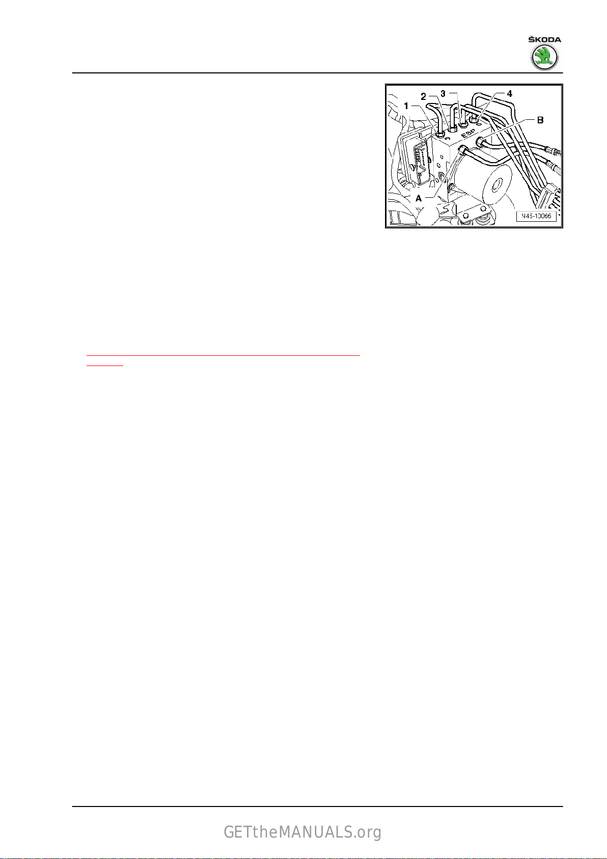
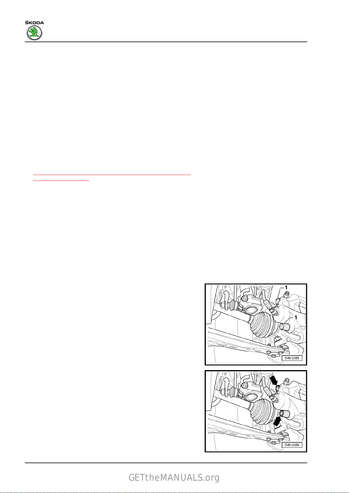
plug connections -1- to -4- out of the bracket, disconnect
and expose electric cables.
chamber.
side.
50 .
3. Control unit and hydraulic unit 25
Page 30

Rapid NH 2013 ➤ , Rapid NH 2014 ➤
GETtheMANUALS.org
Brake systems - Edition 07.2017
– Press down the red fuse -arrow-.
– Unlock the plug connection of the control unit -arrow- and pull
out towards the front.
– Attach the bleeder hose of the bleeding bottle onto the vent
valves of the front left and rear left brake caliper and open vent
valves.
– Press down brake pedal with brake pedal load , e.g. -V.A.G
1869/2- , at least 60 mm.
– Close front left and rear left bleeder valves.
– Do not remove brake pedal load , e. g. -V.A.G 1869/2- .
– Place a sufficient non-fluffing cloths under and around the ABS
control unit - J104- and the ABS hydraulic unit - N55- .
NOTICE
Make sure that no brake fluid gets onto the contacts of the ABS
control unit - J104- .
26 Rep. gr.45 - Anti-lock brake system
Page 31
Rapid NH 2013 ➤ , Rapid NH 2014 ➤
GETtheMANUALS.org
Brake systems - Edition 07.2017
– Mark
– Unscrew the brake lines from the ABS hydraulic unit - N55- ,
– Close the brake lines and threaded holes immediately with
– Mark the brake lines (for brake calliper) -1- to -4-, unscrew and
– Pull ABS hydraulic unit - N55- with ABS control unit - J104-
– Slacken nuts and remove bracket (if it is necessary to remove
♦
brake lines -A- and -B- from the ABS hydraulic unit - N55-
to the master brake cylinder.
unclip from the brackets and lay to the side.
plugs from the repair kit - 1H0 698 311 A- .
close with plugs from the repair kit - 1H0 698 311 A- .
upwards out of the bracket.
the bracket).
Note
If the ABS hydraulic unit - N55- is damaged, the ABS control
unit - J104- must be fully replaced with the ABS hydraulic unit
- N55- .
♦
The ABS control unit - J104- can be separated from the ABS
hydraulic unit - N55-
⇒ “3.3 Disconnecting the control unit from the hydraulic unit”,
page 32 .
♦
The hydraulic pump and the ABS hydraulic unit - N55- must
not be separated from each other.
Installing
Installation is performed in the reverse order; pay attention to the
following points:
Note
♦
Only remove plugs from the new ABS hydraulic unit - N55- if
the relevant brake line is installed.
♦
If the plugs were already removed from the ABS hydraulic unit
- N55- , then brake fluid may escape and adequate filling and
bleeding of the unit can no longer be guaranteed.
♦
Make sure that the rubber bearings are not pressed out of the
console when installing the bracket. After installing, check for
tight fight, otherwise failure may be caused by a malfunction
of the ABS hydraulic unit - N55- .
• Make sure that the multi-pin plug connection latches correctly
with the ABS control unit - J104- .
– Remove brake pedal load , e.g. -V.A.G 1869/2- .
– Bleed brake system.
– Connect the battery and carry out any additional measures
after reconnecting the battery ⇒ Electrical System; Rep. gr.
27 .
– Code new ABS control unit - J104- ⇒ Vehicle diagnostic tester
and adapt.
While doing so, a basic setting of the steering angle sender G85- , the lateral acceleration sender - G200- , the brake pressure
sender 1 - G201- and the longitudinal acceleration sender - G251must be performed ⇒ Vehicle diagnostic tester.
3. Control unit and hydraulic unit 27
Page 32
Rapid NH 2013 ➤ , Rapid NH 2014 ➤
GETtheMANUALS.org
Brake systems - Edition 07.2017
Tightening torques
♦ ⇒ “3.1.3 Summary of components - control unit and hydraulic
unit for ABS/ESC, left-hand drive vehicles up to 21/2015”,
page 19
♦ Bulkhead plenum chamber ⇒ Body Work; Rep. gr. 50 .
♦ Air filter ⇒ Engine; Rep. gr. 23
3.2.2 Removing and installing ABS control
unit - J104- / ABS hydraulic unit - N55- ,
left -hand drive vehicles from 22/2015
Special tools and workshop equipment required
♦ Brake pedal load , e.g. -V.A.G 1869/2♦ Brake filling and bleeding device , e. g. -VAS 5234♦ Repair kit - 1H0 698 311 AThe ABS control unit - J104- is bolted to the ABS hydraulic unit -
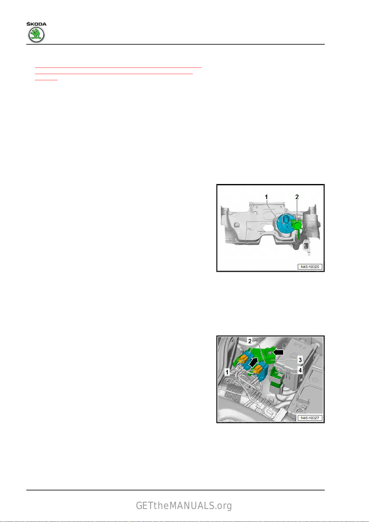
N55- and is located in the engine compartment
-2-.
Note
Do not bend the brake lines in the area of the hydraulic unit.
Removing
– Read out and document the current control unit coding ⇒ Ve‐
hicle diagnostic tester.
– Disconnect battery ⇒ Electrical System; Rep. gr. 27 .
For vehicles with 1.6 MPI engine with automatic gearbox
– Remove battery ⇒ Electrical System; Rep. gr. 27 .
– Undo the mounting bracket with the automatic gearbox control
unit - J217- and place the ⇒ gearbox; Rep. gr. 37 down to the
side.
For vehicles with a 1.4 TDI engine
– Mark
– Remove bracket -3- together with the boost pressure actuator
– Remove bracket with -automatic glow period control unit- J179
For vehicles with a 1.6 TDI engine
– Remove engine cover ⇒ Engine; Rep. gr. 10 .
and pull off connector -1- of the boost pressure actuator
- V465- and the change over valve for the intake manifold valve
- N239- -2-.
- V465- and the change over valve for the intake manifold valve
- N239- , place down to the side.
-4- from the E-box and place to the side.
28 Rep. gr.45 - Anti-lock brake system
Page 33

Rapid NH 2013 ➤ , Rapid NH 2014 ➤
GETtheMANUALS.org
– Loosen hose clamp -1- and remove the complete air filter
housing -2- ⇒ Engine; Rep. gr. 23 .
Continued for all vehicles
– Press fuse -1- upwards in -direction of arrow-.
– Press locking element -2- upwards in -direction of arrow- and
unlock connector -3-.
– Disconnect connector -3- from ABS control unit - J104- and
place to side.
– Place a sufficient non-fluffing cloths under and around the ABS
control unit - J104- and the ABS hydraulic unit - N55- .
NOTICE
Make sure that no brake fluid gets onto the contacts of the ABS
control unit - J104- .
Brake systems - Edition 07.2017
– Drain the brake fluid from the brake fluid reservoir using the
brake filling and bleeding device e.g. -VAS 5234- .
– Mark brake lines -A- and -B- from the ABS hydraulic unit - N55-
to the master brake cylinder.
– Screw off brake lines -A- and -B- from the ABS hydraulic unit
- N55- and brake cylinder.
– Close the openings on the ABS hydraulic unit - N55- and the
master brake cylinder with screw plugs from the repair kit H0 698 311 A- .
– Unscrew brake lines (to the brake calipers) -1-4- from the ABS
hydraulic unit - N55- .
– Close the brake lines with the screw plugs from the repair kit
- H0 698 311 A- .
3. Control unit and hydraulic unit 29
Page 34

Rapid NH 2013 ➤ , Rapid NH 2014 ➤
GETtheMANUALS.org
Brake systems - Edition 07.2017
– Pull ABS hydraulic unit - N55- with ABS control unit - J104-
upwards out of the bracket.
Note
♦
If the ABS hydraulic unit - N55- is damaged, the ABS control
unit - J104- must be fully replaced with the ABS hydraulic unit
- N55- .
♦
The ABS control unit - J104- can be separated from the ABS
hydraulic unit - N55-
⇒ “3.3 Disconnecting the control unit from the hydraulic unit”,
page 32 .
♦
The hydraulic pump and the ABS hydraulic unit - N55- must
not be separated from each other.
Installing
Installation is performed in the reverse order; pay attention to the
following points:
Note
♦
Only remove plugs from the new ABS hydraulic unit - N55- if
the relevant brake line is installed.
♦
If the plugs were already removed from the ABS hydraulic unit
- N55- , then brake fluid may escape and adequate filling and
bleeding of the unit can no longer be guaranteed.
♦
Make sure that the rubber bearings are not pressed out of the
console when installing the bracket. After installing, check for
tight fight, otherwise failure may be caused by a malfunction
of the ABS hydraulic unit - N55- .
– Bleed brake system
– Connect the battery and carry out any additional measures
after reconnecting the battery ⇒ Electrical System; Rep. gr.
27 .
– Code the control unit - J104- ⇒ Vehicle diagnostic tester.
While doing so, a basic setting of the steering angle sender -
G85-
, the lateral acceleration sender - G200- , the brake pressure
sender 1 - G201- and the longitudinal acceleration sender - G251must be performed ⇒ Vehicle diagnostic tester.
Tightening torques
⇒ “3.1.4 Summary of components - control unit and hydraulic
♦
unit for ABS/ESC, right-hand drive vehicles from 22/2015”,
page 21
⇒ “6 Hydraulic system”, page 152 .
3.2.3 Removing and installing ABS control
unit
- J104- / ABS hydraulic unit - N55- ,
right-hand drive vehicles
Removing
Special tools and workshop equipment required
♦ Brake pedal load , e.g. -V.A.G 1869/2♦ Brake filling and bleeding device , e. g. -VAS 5234♦ Repair kit - 1H0 698 311 A-
30 Rep. gr.45 - Anti-lock brake system
Page 35

Rapid NH 2013 ➤ , Rapid NH 2014 ➤
GETtheMANUALS.org
Fitting location:
The ABS control unit - J104- is bolted to the ABS hydraulic unit -
N55- and is located in the engine compartment on the left side.
– Disconnect battery ⇒ Electrical System; Rep. gr. 27 .
– Remove engine cover ⇒ Engine; Rep. gr. 10 .
– Remove air filter ⇒ Engine; Rep. gr. 24 (fuel engines) or ⇒
Engine; Rep. gr. 23 (diesel engines).
– Press fuse -2- in -direction of arrow-.
– Unlock fuse -1- for plug -3-.
– Disconnect connector -3-.
Brake systems - Edition 07.2017
– Position brake pedal load , e.g. -V.A.G 1869/2- .
– Attach the bleeder hose of the bleeding bottle onto the vent
– Press down brake pedal with brake pedal load , e.g. -V.A.G
– Close front left and rear left bleeder valves.
– Do not remove brake pedal load , e. g. -V.A.G 1869/2- .
– Place a sufficient non-fluffing cloths under and around the ABS
of the front left and rear left brake caliper and open vent
valves
valves.
1869/2- , at least 60 mm.
control unit - J104- and the ABS hydraulic unit - N55- .
NOTICE
Make sure that no brake fluid gets onto the contacts of the ABS
control unit - J104- .
– Mark brake lines -A- and -B- from the master brake cylinder
and unscrew from the ABS hydraulic unit - N55- .
– Close the brake lines and threaded holes immediately with
plugs from the repair kit - 1H0 698 311 A- .
– Mark
– Close the brake lines and threaded holes immediately with
the remaining brake lines -1- to -4- and unscrew from the
ABS hydraulic unit - N55- .
plugs from the repair kit - 1H0 698 311 A- .
3. Control unit and hydraulic unit 31
Page 36

Rapid NH 2013 ➤ , Rapid NH 2014 ➤
GETtheMANUALS.org
Brake systems - Edition 07.2017
– Pull ABS hydraulic unit - N55- with ABS control unit - J104-
upwards out of the bracket.
– Slacken
the bracket).
♦
If the ABS hydraulic unit - N55- is damaged, the ABS control
nuts and remove bracket (if it is necessary to remove
Note
unit - J104- must be fully replaced with the ABS hydraulic unit
- N55- .
♦
The ABS control unit - J104- can be separated from the ABS
hydraulic unit - N55-
⇒ “3.3 Disconnecting the control unit from the hydraulic unit”,
page 32 .
♦
The hydraulic pump and the ABS hydraulic unit - N55- must
not be separated from each other.
Installing
Installation is performed in the reverse order; pay attention to the
following points:
Note
♦
Only remove plugs from the new ABS hydraulic unit - N55- if
the relevant brake line is installed.
♦
If the plugs were already removed from the ABS hydraulic unit
- N55- , then brake fluid may escape and adequate filling and
bleeding of the unit can no longer be guaranteed.
♦
Make sure that the rubber bearings are not pressed out of the
console when installing the bracket. After installing, check for
tight fight, otherwise failure may be caused by a malfunction
of the ABS hydraulic unit - N55- .
– Bleed brake system
– Connect the battery and carry out any additional measures
after reconnecting the battery ⇒ Electrical System; Rep. gr.
27 .
– Code the control unit - J104- ⇒ Vehicle diagnostic tester.
While doing so, a basic setting of the steering angle sender -
G85-
, the lateral acceleration sender - G200- , the brake pressure
sender 1 - G201- and the longitudinal acceleration sender - G251must be performed ⇒ Vehicle diagnostic tester.
Tightening torques
⇒ “3.1.5 Summary of components - control unit and hydraulic
♦
unit for ABS/ESC, right-hand drive vehicles”, page 23
⇒ “6 Hydraulic system”, page 152 .
3.3 Disconnecting the control unit from the
hydraulic unit
♦ In the case of a malfunction of the ABS control unit - J104- ,
the
control unit must be disconnected from the ABS hydraulic
unit - N55- and replaced individually.
♦ In the case of a malfunction of the ABS hydraulic unit - N55- ,
the ABS hydraulic unit - N55- must be completely replaced
together with the ABS control unit - J104- .
32 Rep. gr.45 - Anti-lock brake system
Page 37

Rapid NH 2013 ➤ , Rapid NH 2014 ➤
GETtheMANUALS.org
NOTICE
♦ The hydraulic pump - V64- and ABS hydraulic unit - N55-
must not be separated from each other.
♦ On a disconnected ABS control unit - J104- , the printed cir‐
cuit board is exposed.
♦ No moisture and no dirt particles must penetrate into the in‐
terior of the ABS control unit - J104- .
♦ Before handling the ABS control unit - J104- , the technician
must discharge himself electrostatically. The electrostatic
discharge is achieved by touching earthed metal parts. Do
not grab directly at the plug contacts or electronic compo‐
nents.
Note
Electrostatic charge can cause malfunctions of the ABS control
unit - J104- .
– Remove the ABS hydraulic unit - N55- with the ABS control
unit - J104-
⇒ “3.2 Removing and installing ABS control unit J104 / ABS
hydraulic unit N55 ”, page 25 .
– Lay the ABS hydraulic unit - N55- with the ABS control unit -
J104- on a clean flat surface facing upwards.
– Unscrew the fixing screws -arrows- of the ABS control unit -
J104- -1new screws).
and place aside immediately (danger of mix-ups with
Brake systems - Edition 07.2017
3. Control unit and hydraulic unit 33
Page 38

Rapid NH 2013 ➤ , Rapid NH 2014 ➤
GETtheMANUALS.org
Brake systems - Edition 07.2017
– Separate
unit - N55- in the -direction of arrow-.
The ABS control unit - J104- may not tilt when it is pulled off from
the ABS hydraulic unit - N55- .
– Cover the solenoid coils of the ABS control unit - J104- with a
non-fluffing cloth.
After separating from the ABS control unit - J104- and the ABS
hydraulic unit - N55- , use the transport protection for valve
domes.
– Check the sealing surface of the ABS hydraulic unit - N55- for
cleanliness. If necessary clean with white spirits and a nonfluffing cloth.
♦
The sealing surface of the ABS control unit - J104- may not be
repaired using a file, metal scraper or similar.
♦
If the sealing surface is damaged, replace the sealing surface
of the ABS control unit - J104- .
♦
The seal of the ABS control unit - J104- must not be damaged.
♦
The seal is not designed as spare part, so it is part of the new
ABS control unit - J104- .
the ABS control unit - J104- from the ABS hydraulic
Note
Note
3.4 Fitting the control unit to the hydraulic
unit
NOTICE
Strong vibrations (e.g. fall, knock) can destroy the ABS control
unit - J104- . The ABS control unit - J104- must no longer be
used.
• The contact surfaces must be cleaned before assembling.
• The seal of the ABS control unit - J104- must not be damaged.
– Position the ABS control unit - J104- without tilting it onto the
ABS hydraulic unit - N55- .
34 Rep. gr.45 - Anti-lock brake system
Page 39

Rapid NH 2013 ➤ , Rapid NH 2014 ➤
GETtheMANUALS.org
Brake systems - Edition 07.2017
– Tighten
⇒ page 35 .
♦
The threads in the ABS hydraulic unit - N55- must not be re‐
the screws in the order -1-, -2-, -3-, -4- in three stages
Note
paired or recut.
♦
If the thread is damaged, the ABS hydraulic unit - N55- must
be replaced.
Note
A new control unit may only be installed on the same hydraulic
unit twice as a maximum to ensure that the elastic seal is still leaktight.
Tightening torques
Component Tightening torque
ABS hydraulic unit - J104- to ABS control unit - N55- - 1st stage 1.5
ABS hydraulic unit - J104- to ABS control unit - N55- - 2nd stage 2.5 Nm
ABS control unit - J104- to ABS hydraulic unit - N55- - 3rd stage 3.5 Nm
3. Control unit and hydraulic unit 35
Page 40

Rapid NH 2013 ➤ , Rapid NH 2014 ➤
GETtheMANUALS.org
Brake systems - Edition 07.2017
4 Sensors
⇒ “4.1 Removing and installing front speed sensors G45 / G47 ”,
page 36
⇒ “4.2 Removing and installing the rear speed sensors G44 / G46
”, page 36
4.1 Removing and installing front speed
sensors -G45- / -G47-
Removing
– Raise vehicle.
– Disconnect connector -1- on the front wheel speed sensor .
– Release screw -3-.
– Pull front speed sensor -2- out of the wheel bearing housing.
Installing
– Installation is performed in the reverse order; pay attention to
the following points:
– Before inserting the front speed sensor , clean the inner sur‐
face of the hole and moisten with hot bolt paste - G 052 112
A3- .
Tightening torques
♦ ⇒ “1.1 Assembly overview - front brakes”, page 38
4.2 Removing and installing the rear speed
sensors -G44- / -G46-
Note
The procedure for removal and installation of the speed sensor is
identical for vehicles with drum brakes and for vehicles with disc
brakes.
Removing
– Raise vehicle.
– Disconnect connector -1- on the rear speed sensor .
36 Rep. gr.45 - Anti-lock brake system
Page 41

Rapid NH 2013 ➤ , Rapid NH 2014 ➤
GETtheMANUALS.org
– Unscrew screw -arrow-.
Note
The wheel speed sensor is shown on the vehicle with disc brakes.
– Pull the rear speed sensor -1- out of the opening in the axle
stud and unclip its cables on the axle.
Installing
– Installation is carried out in the reverse order.
Tightening torques
♦
⇒ “2.1.1 Summary of components - rear axle brake, drum
brake”, page 52
♦ ⇒ “2.1.3 Summary of components - rear axle brake, disc
brake”, page 56
Brake systems - Edition 07.2017
4. Sensors 37
Page 42

Rapid NH 2013 ➤ , Rapid NH 2014 ➤
GETtheMANUALS.org
Brake systems - Edition 07.2017
46 – Brakes - mechanism
1 Front brakes
⇒ “1.1 Assembly overview - front brakes”, page 38
⇒ “1.2 Removing and installing brake pads”, page 41
⇒ “1.3 Removing and installing brake caliper”, page 46
1.1 Assembly overview - front brakes
⇒ “1.1.1 Summary of components - front brake FS-III”,
page 38
⇒ “1.1.2 Summary of components - front brake FN3”, page 40
1.1.1 Summary of components - front brake FS-III
Note
♦
Observe the instructions for changing the pad
⇒ “1.2.1 Changing the brake pads of the front brake - Mounting instructions”, page 41
♦
Brake inspection ⇒ “4 Brake inspection”, page 6 .
♦
After replacing the brake pads, depress brake pedal firmly several times when the vehicle is stationary to
ensure the brake pads are properly seated in their normal operating position.
♦
Use the brake filling and bleeding device , e.g. -VAS 5234- , to drain the brake fluid from the brake fluid
reservoir.
♦
Use the brake pedal load , e.g. -V.A.G 1869/2- , before removing a brake calliper or separating a brake hose
from the brake calliper.
38 Rep. gr.46 - Brakes - mechanism
Page 43
Rapid NH 2013 ➤ , Rapid NH 2014 ➤
GETtheMANUALS.org
Brake systems - Edition 07.2017
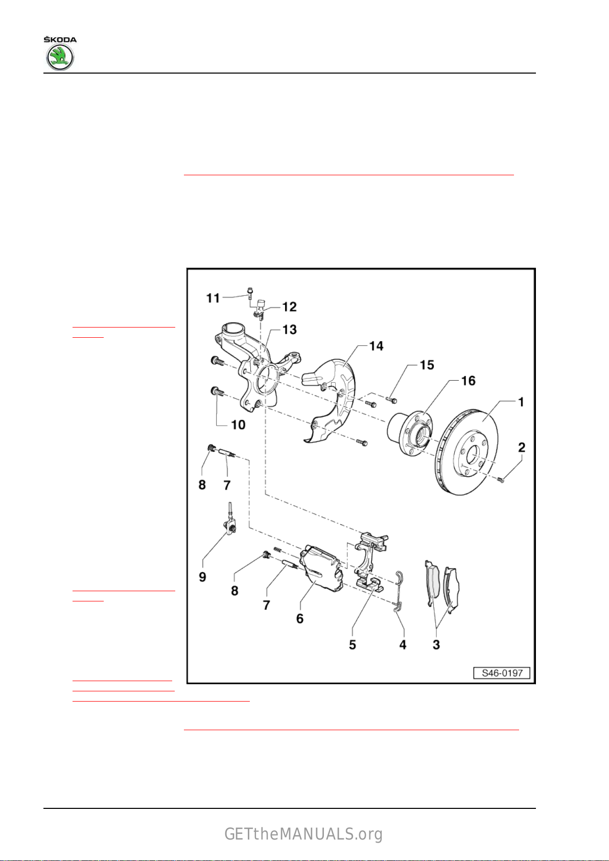
1 - Brake disc
❑ internally ventilated
❑ Dimensions and wear
limit
⇒ “3.1.2 Front brakes”,
page 3
❑ always replace axle-
wise
❑ unscrew the brake cali‐
per before removing
❑ Do not use force to sep‐
arate the brake discs
from the wheel hub, if
necessary use rust sol‐
vent; as you could oth‐
erwise damage the
brake discs.
❑ Assignment ⇒ Electron‐
ic Catalogue of Original
Parts
2 - Screw
❑ 8 Nm
3 - Brake pads
❑ Dimensions and wear
limit
⇒ “3.1.2 Front brakes”,
page 3
❑ Inspect thickness
⇒ Maintenance ; Book‐
let Rapid NH
❑ Observe the instruc‐
tions for changing the
pad
⇒ “1.2.1 Changing the
brake pads of the front
brake - Mounting in‐
structions”, page 41
❑ always replace axle-wise
❑ Removing and installing
⇒ “1.2.2 Removing and installing brake pads, floating caliper disc brake FS-III”, page 42
4 - Brake caliper
❑ Removing and installing ⇒ “1.3.1 Removing and installing brake caliper FS-III”, page 46
❑ Summary of components ⇒ “1.1.1 Exploded view – front brake caliper - brake FS III”, page 90
❑ Assignment ⇒ Electronic Catalogue of Original Parts
5 - Guide bolt
❑ 30 Nm
6 - Cap
❑ Disconnect
7 - Tensioning sleeve
8 - Brake hose
❑ with banjo union and hollow screw
❑ 35 Nm
9 - Wheel hub with wheel bearing
❑ for vehicles with ABS the sensor ring is built into the wheel hub
1. Front brakes 39
Page 44
Rapid NH 2013 ➤ , Rapid NH 2014 ➤
GETtheMANUALS.org
Brake systems - Edition 07.2017
10 - Screw
❑
12 Nm
11 - Cover plate
12 - Wheel bearing housing
13 - ABS wheel speed sensor
❑ Removing and installing
14 - Screw
❑
8 Nm
⇒ “4.1 Removing and installing front speed sensors G45 / G47 ”, page 36
1.1.2 Summary of components - front brake FN3
1 - Brake disc
❑ internally ventilated
❑ Dimensions and wear
limit
⇒ “3.1.2 Front brakes”,
page 3
❑
always replace axle-
wise
❑ To remove, detach the
brake caliper -6- and
brake carrier -5- first
❑ Do not use force to sep‐
arate the brake discs
from the wheel hub, if
necessary use rust sol‐
vent; as you could oth‐
erwise damage the
brake discs.
❑ Assignment ⇒ Electron‐
ic Catalogue of Original
Parts
2 - Screw
❑ 8 Nm
3 - Brake pads
❑ Dimensions and wear
limit
⇒ “3.1.2 Front brakes”,
page 3
❑
Inspect thickness
⇒ Maintenance ; Book‐
let Rapid NH
❑ Observe the instruc‐
tions for changing the
pad
⇒ “1.2.1 Changing the
brake pads of the front
brake - Mounting instructions”, page 41
❑
always replace axle-wise
❑ Removing and installing
4 - Spring
❑
inserted into both bore holes of the brake caliper
5 - Brake carrier
❑ screwed onto the wheel-bearing housing
⇒ “1.2.3 Removing and installing brake pads, brake calliper FN3”, page 44
40 Rep. gr.46 - Brakes - mechanism
Page 45

Rapid NH 2013 ➤ , Rapid NH 2014 ➤
GETtheMANUALS.org
6 - Brake caliper
❑
Removing and installing
❑
Summary of components
❑
Assignment ⇒ Electronic Catalogue of Original Parts
7 - Guide bolt
❑ 30 Nm
8 - Cap
❑ remove
9 - Brake hose
❑ with banjo union and hollow screw
❑ 35 Nm
10 - Screw
❑ clean when using again
❑ 124 Nm
11 - Screw
❑ 8 Nm
12 - ABS wheel speed sensor
❑ Removing and installing
13 - Wheel bearing housing
14 - Cover plate
15 - Screw
❑
12 Nm
16 - Wheel hub with wheel bearing
❑ for vehicles with ABS the sensor ring is built into the wheel hub
⇒ “1.3.2 Removing and installing brake caliper FN3”, page 49
⇒ “1.1.2 Exploded view – front brake caliper - brake FN3”, page 92
⇒ “4.1 Removing and installing front speed sensors G45 / G47 ”, page 36
Brake systems - Edition 07.2017
1.2 Removing and installing brake pads
⇒ “1.2.1 Changing the brake pads of the front brake - Mounting
instructions”, page 41
⇒ “1.2.2 Removing and installing brake pads, floating caliper disc
brake FS-III”, page 42
⇒ “1.2.3 Removing and installing brake pads, brake calliper FN3”,
page 44
1.2.1 Changing the brake pads of the front
brake - Mounting instructions
When changing the pads, pay attention to the following points:
– Check protective collar of brake calliper piston.
Replace protective cap if damaged.
When replacing the protective cap:
– Check the contact surfaces of the brake piston and the brake
caliper for any dirt (oxidation).
Carefully clean the piston as well as the brake caliper if dirty and
replace the sealing cap.
– Check the brake piston and the brake caliper (corrosion,
grooves on the outside of the cylinder surface), replace the
brake caliper completely if damaged.
For brake caliper piston, press into the initial position:
1. Front brakes 41
Page 46
Rapid NH 2013 ➤ , Rapid NH 2014 ➤
GETtheMANUALS.org
Brake systems - Edition 07.2017
– Check if the piston can be slightly pressed into the brake cal‐
iper.
If the piston cannot be slightly pressed into the brake caliper:
– Check
replace sealing sleeve and protective cap.
Replace the brake caliper completely if damaged.
and clean the brake piston as well as the brake caliper,
1.2.2 Removing and installing brake pads,
floating caliper disc brake FS-III
Special tools and workshop equipment required
♦ Piston jig - T10145-
Note
♦
Observe the instructions for changing the pad
⇒ “1.2.1 Changing the brake pads of the front brake - Mounting
instructions”, page 41 .
♦
When removing mark the brake pads (inner, outer) you intend
to keep using. Fit in same position when installing, or braking
will be uneven!
♦
After replacing the brake pads, depress brake pedal firmly
several times when the vehicle is stationary to ensure the
brake pads are properly seated in their normal operating po‐
sition.
♦
Do not unscrew the brake hose when replacing the brake pad.
Removing
– Remove front wheels.
– If present, disconnect the connector for the brake pad wear
indicator.
– Remove caps -1-.
– Unscrew and remove the two guide bolts -arrows- from the
brake caliper.
42 Rep. gr.46 - Brakes - mechanism
Page 47
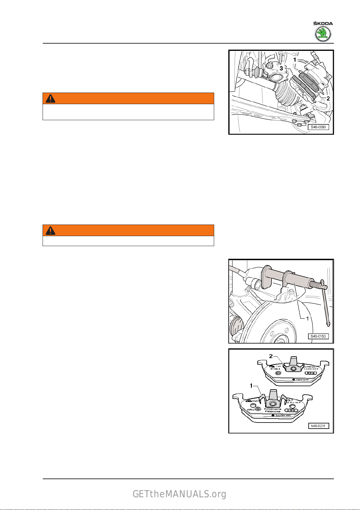
– Remove the brake caliper -1- and secure with wire in such a
GETtheMANUALS.org
way that the weight of the brake caliper does not burden or
damage the brake hose.
– Remove brake pads -2- and -3- from the brake caliper.
Clean
WARNING
Do not flush the brake system with compressed air. The dust
that is generated is hazardous to health!
– Thoroughly clean guiding surface for brake pads on brake
carrier and remove corrosion.
– Clean brake caliper.
Note
Use spirits only to clean the brake caliper housing.
Installing
• Drain some brake fluid from the brake fluid reservoir before
resetting the pistons. Otherwise, particularly if reservoir has
been topped up, fluid will overflow and cause damage.
Rapid NH 2013 ➤ , Rapid NH 2014 ➤
Brake systems - Edition 07.2017
WARNING
Brake fluid is toxic and must never be sucked up by mouth!
– Push piston back with piston jig - T10145- -1-.
Note
Different version of the inner and outer brake pad. Do not mix up
when installing
– Insert the inner brake pad -1- (with the large 3-finger clip with
metallic gloss and with the marking “piston side” on the steel
supporting plate) on the piston.
– Insert the outer brake pad -2- (with the small black 3-finger
clip) into the brake caliper housing.
1. Front brakes 43
Page 48

Rapid NH 2013 ➤ , Rapid NH 2014 ➤
GETtheMANUALS.org
Brake systems - Edition 07.2017
– First
– Tilt the brake caliper so that the guide bolts of the brake caliper
The bolts of the brake caliper -arrows- must only be inserted into
the brake caliper in such a way that the brake caliper can be tilted.
– Screw on both guide bolts -arrows- on the wheel bearing
– Connect
– Insert the caps of the guide bolts.
– Install front wheels.
• After each brake pad replacement, forcefully apply the brake
• Check brake fluid level after replacing the brake pads, if nec‐
Tightening torques
♦
♦ Wheel bots ⇒ Wheels, tyres; Rep. gr. 44
position the brake caliper with brake pads on the bottom
wheel bearing housing -arrow-.
are flush with the threaded holes of the wheel-bearing hous‐
ing.
housing.
the plug connection for the brake pad wear indicator
(where the vehicle is fitted with this).
pedal repeatedly to ensure the brake pads go into their normal
operating position.
essary top up with brake fluid.
⇒ “1.1.1 Summary of components - front brake FS-III”,
page 38
1.2.3 Removing and installing brake pads, brake calliper FN3
Special tools and workshop equipment required
♦ Piston jig - T10145-
• Observe the instructions for changing the pad
⇒ “1.2.1 Changing the brake pads of the front brake - Mounting
instructions”, page 41 .
• When removing mark the brake pads (inner, outer) you intend
to keep using. Fit in same position when installing, or braking
will be uneven!
• After replacing the brake pads, depress brake pedal firmly
several times when the vehicle is stationary to ensure the
brake pads are properly seated in their normal operating po‐
sition.
• Do not unscrew the brake hose when replacing the brake pad.
Removing
– Remove front wheels.
– If present, disconnect the connector for the brake pad wear
indicator.
44 Rep. gr.46 - Brakes - mechanism
Page 49

Rapid NH 2013 ➤ , Rapid NH 2014 ➤
GETtheMANUALS.org
Brake systems - Edition 07.2017
– Lever
– Remove caps -arrows-.
up the retaining spring of the brake pads out of the brake
caliper -arrow- using a screwdriver and remove.
– Loosen and remove the two guide bolts -arrows- from the
brake caliper.
– Remove brake caliper and secure with wire so that weight of
brake caliper does not strain or damage brake hose.
– Take out the brake pads from the brake caliper or from the
brake carrier.
Clean
WARNING
Do not flush the brake system with compressed air. The dust
that is generated is hazardous to health!
– Thoroughly clean guiding surface for brake pads on brake
carrier and remove corrosion.
– Clean brake caliper.
Note
Use spirits only to clean the brake caliper housing.
Installing
• Drain some brake fluid from the brake fluid reservoir before
resetting the pistons. Otherwise, particularly if reservoir has
been topped up, fluid will overflow and cause damage.
WARNING
Brake fluid is toxic and must never be sucked up by mouth!
1. Front brakes 45
Page 50

Rapid NH 2013 ➤ , Rapid NH 2014 ➤
GETtheMANUALS.org
Brake systems - Edition 07.2017
– Push piston back with piston jig - T10145- -1-.
– Remove the protective foil from the supporting plate of the
outer brake pad.
– Place the outer brake pad on the brake carrier.
– Insert the inner brake pad with retaining spring into the brake
caliper (piston).
When installing the brake caliper make sure that the brake pad
does not stick to the brake caliper before reaching its correct in‐
stalled position.
Do not damage the surface to be glued.
– Screw
– Insert both caps.
– Insert retaining spring in brake caliper.
– If present, connect the connector for the brake pad wear indi‐
– Attach the wheels.
• After each brake pad replacement, forcefully apply the brake
• Check brake fluid level after changing brake pads.
Tightening torques
♦
♦ Wheel bots ⇒ Wheels, tyres; Rep. gr. 44
the brake caliper with both guide bolts to the brake car‐
rier.
cator.
pedal repeatedly to ensure the brake pads go into their normal
operating position.
⇒ “1.1.2 Summary of components - front brake FN3”,
page 40
1.3 Removing and installing brake caliper
⇒ “1.3.1 Removing and installing brake caliper FS-III”,
page 46
⇒ “1.3.2 Removing and installing brake caliper FN3”, page 49
1.3.1 Removing and installing brake caliper
FS-III
Special tools and workshop equipment required
♦ Brake pedal load e.g. -V.A.G 1869/2♦ Bleeding bottle (commercially available)
46 Rep. gr.46 - Brakes - mechanism
Page 51

Rapid NH 2013 ➤ , Rapid NH 2014 ➤
GETtheMANUALS.org
Note
♦
Observe the instructions for changing the pad
⇒ “1.2.1 Changing the brake pads of the front brake - Mounting
instructions”, page 41 .
♦
When removing mark the brake pads (inner, outer) you intend
to keep using. Fit in same position when installing, or braking
will be uneven!
♦
After replacing the brake pads, depress brake pedal firmly
several times when the vehicle is stationary to ensure the
brake pads are properly seated in their normal operating po‐
sition.
♦
Do not unscrew the brake hose when replacing the brake pad.
Removing
– Remove front wheel.
– If present, disconnect the connector for the brake pad wear
indicator.
– Brake pedal load e.g. -V.A.G 1869/2– Attach the bleeder hose of the bleeding bottle onto the vent
valve of the brake caliper and then open then bleeder valve.
– Press the brake pedal by at least 60 mm and lock with brake
pedal load , e. g. -V.A.G 1869/2- .
– Do not remove brake pedal load , e. g. -V.A.G 1869/2- .
– Close the vent valve and remove the bleeding bottle.
– Remove brake hose.
Brake systems - Edition 07.2017
– Remove caps -1-.
1. Front brakes 47
Page 52

Rapid NH 2013 ➤ , Rapid NH 2014 ➤
GETtheMANUALS.org
Brake systems - Edition 07.2017
– Unscrew and remove the two guide bolts -arrows- from the
brake caliper.
– Remove brake calliper from the wheel bearing housing.
– Take out the brake pads from the brake caliper.
Clean
WARNING
Do not flush the brake system with compressed air. The dust
that is generated is hazardous to health!
– Thoroughly clean guiding surface for brake pads on brake
carrier and remove corrosion.
– Clean brake caliper.
Note
Use spirits only to clean the brake caliper housing.
Installing
• The piston is pushed back.
Note
Different version of the inner and outer brake pad. Do not mix up
when installing
– Insert the inner brake pad -1- (with the large 3-finger clip with
metallic gloss and with the marking “piston side” on the steel
supporting plate) on the piston.
– Insert the outer brake pad -2- (with the small black 3-finger
clip) into the brake caliper housing.
– First,
– Tilt the brake caliper so that the guide bolts of the brake caliper
The bolts of the brake caliper -arrows- must only be inserted into
the brake caliper in such a way that the brake caliper can be tilted.
position the brake caliper with the brake pads at the bot‐
tom -arrow- of the brake carrier.
are flush with the threaded holes of the wheel-bearing hous‐
ing.
48 Rep. gr.46 - Brakes - mechanism
Page 53

Rapid NH 2013 ➤ , Rapid NH 2014 ➤
GETtheMANUALS.org
– Screw on both guide bolts -arrows- on the wheel bearing
housing.
– If
present, connect the connector for the brake pad wear indi‐
cator.
– Insert the caps of the guide bolts.
– Bolt brake hose to brake caliper.
– Remove brake pedal load e.g. -V.A.G 1869/2- .
– Bleed brake system
⇒ “6.2 Prebleeding the hydraulic system”, page 152 .
– Install wheel ⇒ Wheels, Tyres; Rep. gr. 44 .
• Firmly depress brake pedal several times with vehicle station‐
ary
so that the brake pads are properly seated in their normal
operating position.
• Check brake fluid level.
Tightening torques
⇒ “1.1.1 Summary of components - front brake FS-III”,
♦
page 38
♦ Wheel bots ⇒ Wheels, tyres; Rep. gr. 44
Brake systems - Edition 07.2017
1.3.2 Removing and installing brake caliper
FN3
Special tools and workshop equipment required
♦ Brake pedal load , e.g. -V.A.G 1869/2-
Note
♦
Observe the instructions for changing the pad
⇒ “1.2.1 Changing the brake pads of the front brake - Mounting
instructions”, page 41 .
♦
When removing mark the brake pads (inner, outer) you intend
to keep using. Fit in same position when installing, or braking
will be uneven!
♦
After replacing the brake pads, depress brake pedal firmly
several times when the vehicle is stationary to ensure the
brake pads are properly seated in their normal operating po‐
sition.
♦
Do not unscrew the brake hose when replacing the brake pad.
Removing
– Remove front wheel.
– If present, disconnect the connector for the brake pad wear
indicator.
1. Front brakes 49
Page 54

Rapid NH 2013 ➤ , Rapid NH 2014 ➤
GETtheMANUALS.org
Brake systems - Edition 07.2017
– Insert brake pedal load, , e.g. -V.A.G 1869/2- .
– Attach the bleeder hose of the bleeding bottle onto the vent
valve of the brake caliper and then open then bleeder valve.
– Press the brake pedal by at least 60 mm and lock with brake
pedal load , e. g. -V.A.G 1869/2- .
– Do not remove brake pedal load , e. g. -V.A.G 1869/2- .
– Close the vent valve and remove the bleeding bottle.
– Lever
– Remove caps -arrows-.
up the retaining spring of the brake pads out of the brake
caliper -arrow- using a screwdriver and remove.
50 Rep. gr.46 - Brakes - mechanism
Page 55

Rapid NH 2013 ➤ , Rapid NH 2014 ➤
GETtheMANUALS.org
– Loosen and remove the two guide bolts -arrows- from the
brake caliper.
– Pull off brake caliper from brake carrier.
– Take out the brake pads from the brake caliper.
Clean
WARNING
Do not flush the brake system with compressed air. The dust
that is generated is hazardous to health!
– Thoroughly clean guiding surface for brake pads on brake
carrier and remove corrosion.
– Clean brake caliper.
Note
Use spirits only to clean the brake caliper housing.
Installing
• The piston is pushed back.
• The outside brake pad is fitted on the brake carrier.
– Insert the inner brake pad with retaining spring into the brake
caliper (piston).
When installing the brake caliper make sure that the brake pad
does not stick to the brake caliper before reaching its correct in‐
stalled position.
Do not damage the surface to be glued.
– Screw the brake caliper with both guide bolts to the brake car‐
rier.
– Insert both caps.
– Bolt brake hose to brake caliper.
– Remove brake pedal load e.g. -V.A.G 1869/2- .
– Insert retaining spring in brake caliper.
– If present, connect plug connection of the brake pad wear in‐
dicator.
– Bleed brake system
⇒ “6.2 Prebleeding the hydraulic system”, page 152 .
– Attach the wheels.
• Firmly depress brake pedal several times with vehicle station‐
ary
so that the brake pads are properly seated in their normal
operating position.
• Check brake fluid level.
Tightening torques
⇒ “1.1.2 Summary of components - front brake FN3”,
♦
page 40
♦ Wheel bots ⇒ Wheels, tyres; Rep. gr. 44
Brake systems - Edition 07.2017
1. Front brakes 51
Page 56

Rapid NH 2013 ➤ , Rapid NH 2014 ➤
GETtheMANUALS.org
Brake systems - Edition 07.2017
2 Rear brakes
⇒ “2.1 Assembly overview - rear brakes”, page 52
⇒ “2.2 Removing and installing brake pads”, page 58
⇒ “2.3 Removing and installing brake caliper”, page 61
⇒ “2.4 Resetting brake”, page 63
⇒ “2.5 Removing and installing brake anchor plate”, page 64
⇒ “2.6 Removing and installing wheel-brake cylinder”,
page 65
⇒ “2.7 Removing and installing brake shoes”, page 66
2.1 Assembly overview - rear brakes
⇒ “2.1.1 Summary of components - rear axle brake, drum brake”,
page 52
⇒ “2.1.2 Summary of components - drum brake”, page 54
⇒ “2.1.3 Summary of components - rear axle brake, disc brake”,
page 56
2.1.1 Summary of components - rear axle brake, drum brake
Note
♦
Brake inspection ⇒ “4 Brake inspection”, page 6 .
♦
After renewing wheel brake cylinder, brake backplate and brake shoes, depress brake pedal firmly several
times with vehicle stationary so that the brake shoes are properly seated in their normal operating position.
♦
Generally tighten the brake line pipe screws to a tightening torque of 14 Nm.
♦
Use a bleeding bottle, that only comes into contact with the brake fluid, to drain brake fluid from the brake
fluid reservoir. Brake fluid is toxic and must never be sucked up by mouth!
♦
Use brake pedal load , e. g. -V.A.G 1869/2- , before removing a brake cylinder, a brake carrier or before
separating a brake line from the brake cylinder.
52 Rep. gr.46 - Brakes - mechanism
Page 57

1 - Screw
GETtheMANUALS.org
❑
8 Nm
2 - Brake drum
❑ Brake drum diameter,
wear limit
⇒ “3.1.3 Rear brake”,
page 4
❑
clean carefully, and
check damage, dimen‐
sional accuracy and
perfect brake surface
❑ Thoroughly clean the
centering hole of the
drum before installing
and subsequently treat
it with approx. 0.5 g of
anti-corrosion agent AKR 322 000-
Note
The anti-corrosion agent - AKR 322
000- must not get into the threads of
the wheel screws!
Rapid NH 2013 ➤ , Rapid NH 2014 ➤
Brake systems - Edition 07.2017
3 - Cap
❑ Replace after removal
❑ Driving in and out ⇒
Axles, steering; Rep. gr.
42 .
4 - Nut
❑ self-locking
❑ Replace after removal
⇒ Axles, steering; Rep.
gr. 42
5 - Wheel hub with wheel bearing
❑ Sensor ring for ABS is built into the wheel hub
❑ must be replaced completely
❑ removing and installing ⇒ Axles, steering; Rep. gr. 42
❑ Assignment ⇒ Electronic Catalogue of Original Parts
❑ Before installing the brake drum, thoroughly clean the centering shoulder for the brake drum and sub‐
sequently treat it with approx. 0.5 g of anti-corrosion agent - AKR 322 000-
Note
The anti-corrosion agent - AKR 322
000- must not get into the threads of
the wheel screws!
6 - Screw
❑ Replace after removal
❑ Tightening torque ⇒ Axles, steering; Rep. gr. 42
7 - Brake carrier with brake shoes
❑ Removing and installing
Summary of components
❑
8 - Handbrake
Adjusting parking brake
❑
⇒ “2.5 Removing and installing brake anchor plate”, page 64
⇒ “2.1.2 Summary of components - drum brake”, page 54
⇒ “3.2 Adjusting parking brake”, page 72 .
2. Rear brakes 53
Page 58
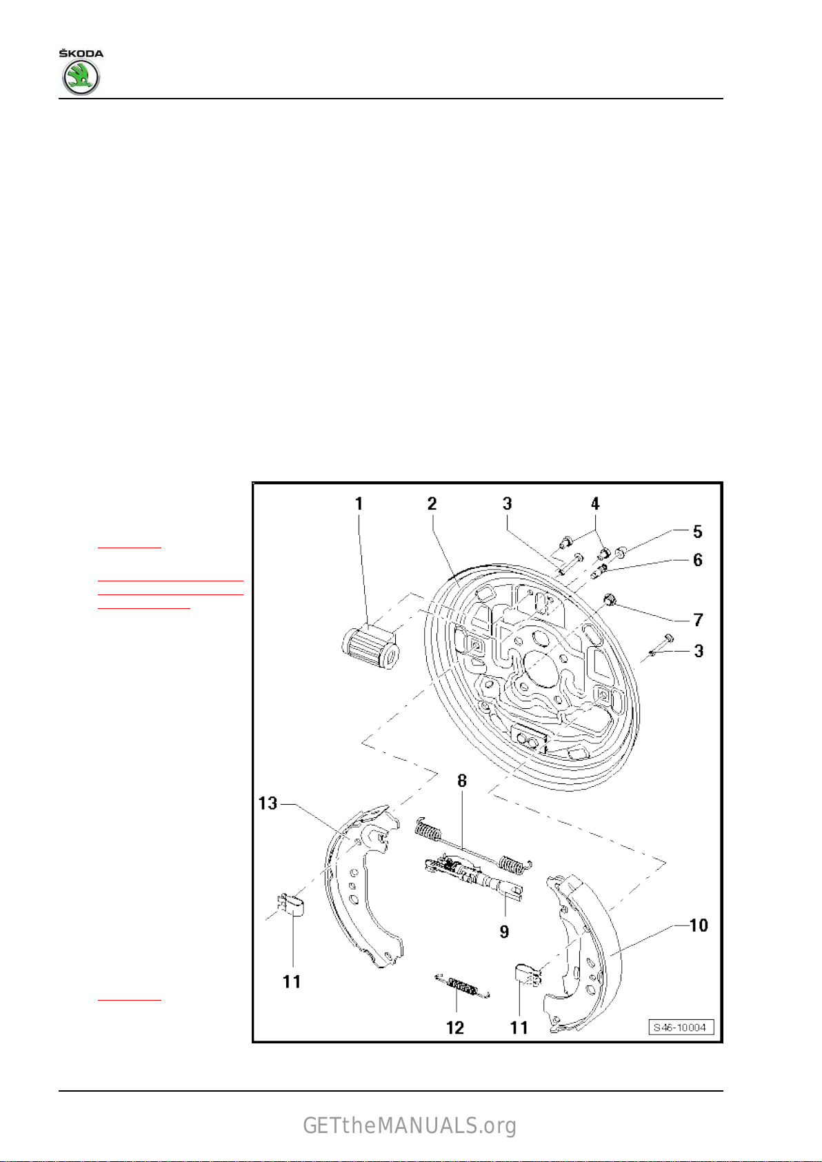
Rapid NH 2013 ➤ , Rapid NH 2014 ➤
GETtheMANUALS.org
Brake systems - Edition 07.2017
9 - Axle stud
❑
removing and installing ⇒ Axles, steering; Rep. gr. 42
❑ Assignment ⇒ Electronic Catalogue of Original Parts
10 - Brake line
❑ 14 Nm
11 - ABS wheel speed sensor
12 - Plug
❑ for vehicles without ABS
❑ to plug the hole for the speed sensor in the axle stud
❑ Assignment ⇒ Electronic Catalogue of Original Parts
13 - Screw
❑ 8 Nm
14 - Axle beam
❑ Assignment ⇒ Electronic Catalogue of Original Parts
2.1.2 Summary of components - drum brake
1 - Wheel-brake cylinder
❑ Repairs not allowed
❑ Check for leaks
⇒ page 56
❑ Removing
⇒ “2.6 Removing and in‐
stalling wheel-brake cyl‐
inder”, page 65
2 - Brake carrier
3 - Fit pin
4 - Screw
❑
10 Nm
5 - Ventilation valve cap
6 - Vent valve
❑ 10 Nm
7 - Plug
❑ remove to check brake
pad thickness
8 - Top brake spring
❑ Grease contact surfa‐
ces with solid lubricant
paste - G 000 6509 - Expansion rod
❑ with thermal clip
❑ with setting wheel and
self-adjuster
❑ Fitting position
⇒ page 56
❑
Grease contact surfa‐
ces with solid lubricant
paste - G 000 650-
and installing
54 Rep. gr.46 - Brakes - mechanism
Page 59
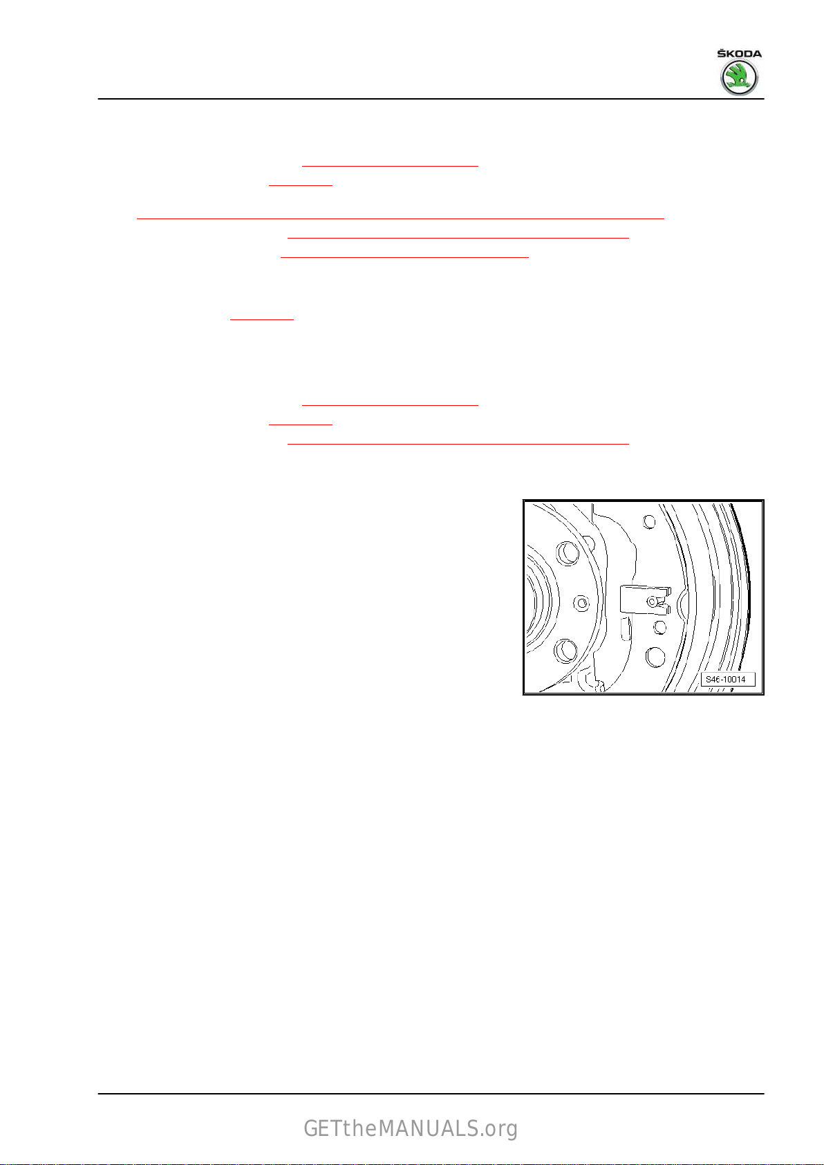
Rapid NH 2013 ➤ , Rapid NH 2014 ➤
GETtheMANUALS.org
Brake systems - Edition 07.2017
10 - Brake shoe
❑
with lever for hand-brake
❑ Dimensions and wear limit
❑
Check pad thickness
❑
Observe the instructions when replacing the brake shoes
⇒ “2.7.1 Replacing the brake shoes of the rear brake - Mounting instructions”, page 66
❑
Removing and installing
❑
Setting the hand-brake
11 - Clamp
❑
for locking the brake shoe
❑ Fitting position
12 - Bottom retractor spring
❑
Grease contact surfaces with solid lubricant paste - G 000 650-
13 - Brake shoe
❑ Dimensions and wear limit
❑
Check pad thickness
❑
Removing and installing
❑
always replace axle-wise
⇒ page 55
⇒ “3.1.3 Rear brake”, page 4
⇒ page 56
⇒ “2.7.2 Removing and installing brake shoes”, page 67
⇒ “3.2 Adjusting parking brake”, page 72
⇒ “3.1.3 Rear brake”, page 4
⇒ page 56
⇒ “2.7.2 Removing and installing brake shoes”, page 67
Fitting position of securing clamp
The securing clamp must point with its closed part to the wheel
hub.
2. Rear brakes 55
Page 60
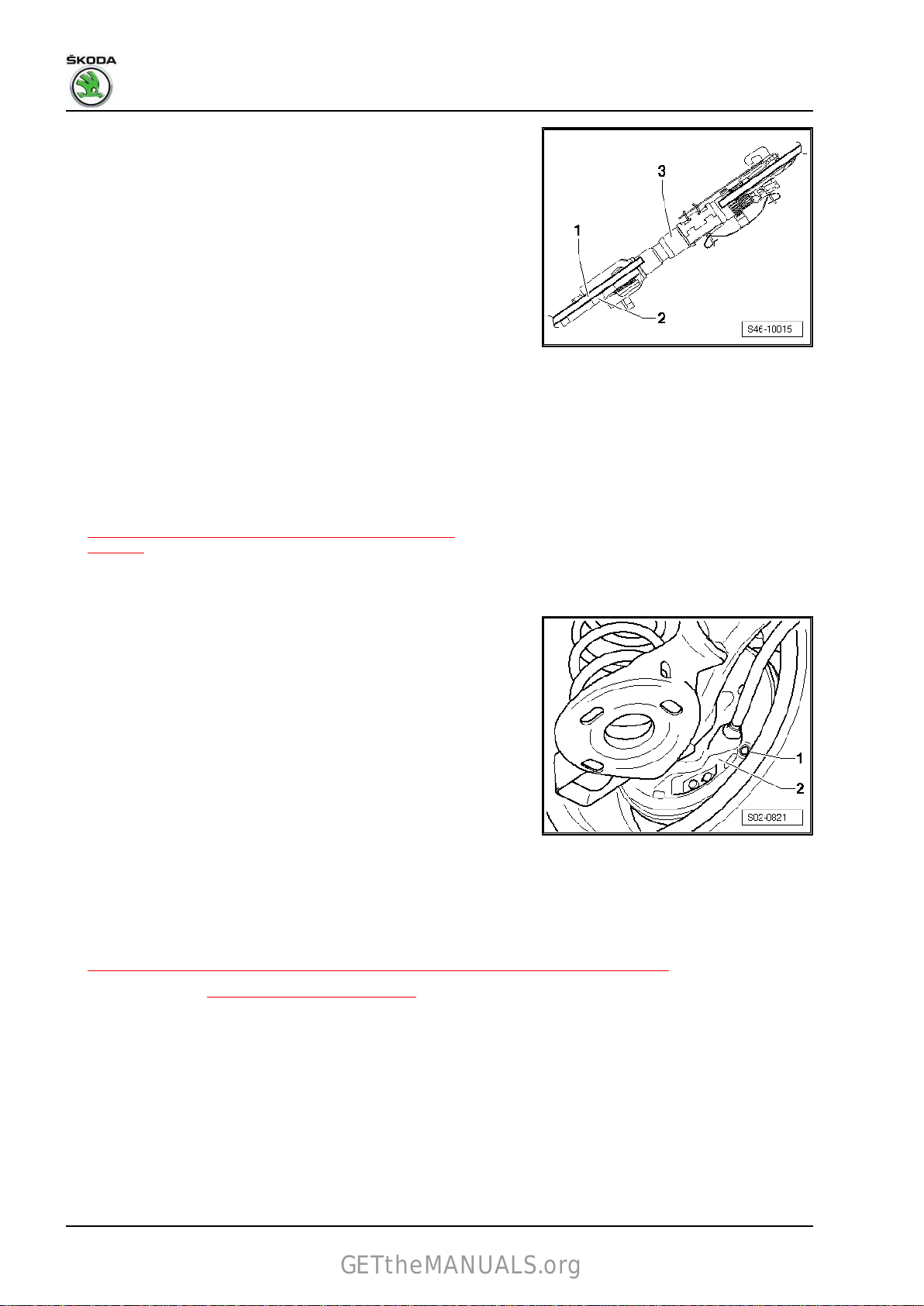
Rapid NH 2013 ➤ , Rapid NH 2014 ➤
GETtheMANUALS.org
Brake systems - Edition 07.2017
Fitting position of expansion rod
1 - Brake shoe
2 - Handbrake lever
3 - Expansion rod with thermal clip
• Thermal clip - bimetal strip must point towards the brake drum.
Checking wheel-brake cylinder for leaks
Note
♦
The tightness test is performed only visually without using any
tools and without removing the dust cap.
♦
The dust cap may get damaged in case of removal.
♦
Slight traces of grease in the area of the wheel-brake cylinder
do not point to a leakage. It is essentially assembly grease.
– Check the wheel-brake cylinder.
– If brake fluid drips out of the wheel-brake cylinder, the wheel-
brake cylinder must be replaced
⇒ “2.6 Removing and installing wheel-brake cylinder”,
page 65 .
Checking the brake pad thickness through the inspection hole in
the brake carrier
– Loosen the cap -1- from the brake carrier -2-.
– Checking
in the brake carrier.
Minimum pad thickness without supporting shoe (wear dimen‐
sion).
the brake pad thickness through the inspection hole
Note
The brake pads must not be soiled with brake fluid or grease.
2.1.3 Summary of components - rear axle brake, disc brake
Note
♦
Observe the instructions for changing the pad
⇒ “2.2.1 Changing the brake pads of the rear brake - Mounting instructions”, page 58
♦
Brake inspection ⇒ “4 Brake inspection”, page 6 .
♦
After replacing the brake pads, depress brake pedal firmly several times when the vehicle is stationary to
ensure the brake pads are properly seated in their normal operating position.
♦
Use the brake filling and bleeding device , e.g. -VAS 5234- , to drain the brake fluid from the brake fluid
reservoir.
♦
Use the brake pedal load , e.g. -V.A.G 1869/2- , before removing a brake calliper or separating a brake hose
from the brake calliper.
♦
Generally tighten the brake line pipe screws to a tightening torque of 14 Nm.
56 Rep. gr.46 - Brakes - mechanism
Page 61
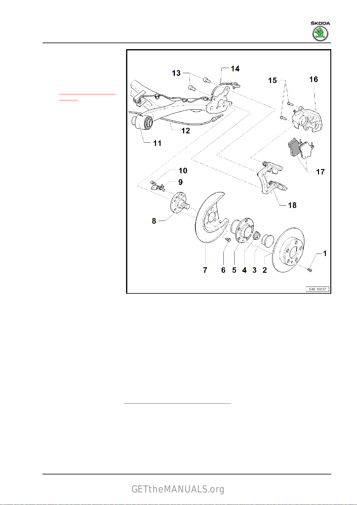
Rapid NH 2013 ➤ , Rapid NH 2014 ➤
GETtheMANUALS.org
1 - Screw
❑ 8 Nm
2 - Brake disc
❑ Dimensions and wear
limit
⇒ “3.1.3 Rear brake”,
page 4
❑ Assignment ⇒ Electron‐
ic Catalogue of Original
Parts
❑ always replace axle-
wise
❑ unscrew the brake cali‐
per before removing
3 - Cap
❑ Replace after removal
❑ pressing off and driving
in ⇒ chassis, axles,
steering; Rep. gr. 42
4 - Nut
❑ self-locking
❑ Tightening torque ⇒
Chassis, axles, steer‐
ing; Rep. gr. 42 .
5 - Wheel hub with wheel bear‐
ing
❑ must be replaced com‐
pletely
❑ removing and installing
⇒ chassis, axles, steer‐
ing; Rep. gr. 42
❑ Assignment ⇒ Electron‐
ic Catalogue of Original
Parts
6 - Screw
❑ Replace after removal
❑ Tightening torque ⇒ Chassis, axles, steering; Rep. gr. 42 .
7 - Cover plate
8 - Axle stud
9 - ABS wheel speed sensor
10 - Screw
❑ 8 Nm
11 - Axle beam
12 - Handbrake
❑ Adjusting parking brake ⇒ “3.2 Adjusting parking brake”, page 72 .
13 - Hexagon socket head bolt
❑ Replace after removal
❑ 30 Nm + 30°.
14 - Brake line
❑ with supports, hollow bolt and seal
❑ must be replaced completely, do not dismantle
❑ do not unscrew when replacing the brake pad
Brake systems - Edition 07.2017
2. Rear brakes 57
Page 62

Rapid NH 2013 ➤ , Rapid NH 2014 ➤
GETtheMANUALS.org
Brake systems - Edition 07.2017
❑ 38 Nm
15 - Screw
❑
self-locking
❑ Replace after removal
❑ 35 Nm
16 - Brake caliper
❑ Removing and installing
17 - Brake pads
❑
Dimensions and wear limit
❑
Inspect thickness ⇒ Maintenance ; Booklet Rapid NH
❑ Observe the instructions for changing the pad
⇒ “2.2.1 Changing the brake pads of the rear brake - Mounting instructions”, page 58
❑
always replace axle-wise
❑ Removing and installing
18 - Brake carrier with guide bolts and protective caps
❑
must be assembled with sufficient grease on the guide bolt, supplied as a spare part
❑ fit a repair set if there is any damage to the protective caps or guide bolts; (use the enclosed grease
packing to lubricate the guide bolts)
❑ Observe the instructions for changing the pad
⇒ “2.2.1 Changing the brake pads of the rear brake - Mounting instructions”, page 58
⇒ “2.3 Removing and installing brake caliper”, page 61
⇒ “3.1.3 Rear brake”, page 4
⇒ “2.2.2 Removing and installing brake pads”, page 58
2.2 Removing and installing brake pads
⇒ “2.2.1 Changing the brake pads of the rear brake - Mounting
instructions”, page 58
⇒ “2.2.2 Removing and installing brake pads”, page 58
2.2.1 Changing the brake pads of the rear brake - Mounting instructions
When changing the pads, pay attention to the following points:
– Check protective collar of brake calliper piston.
Replace protective cap if damaged.
When replacing the protective cap:
– Check the contact surfaces of the brake piston and the brake
caliper for any dirt (oxidation).
Carefully clean the piston as well as the brake caliper if dirty and
replace the sealing cap.
– Check the brake piston and the brake caliper (corrosion,
grooves on the outside of the cylinder surface), replace the
brake caliper completely if damaged.
For brake caliper piston, press into the initial position:
– Check if the piston can be slightly pressed into the brake cal‐
iper.
If the piston cannot be slightly pressed into the brake caliper:
– Check
replace sealing sleeve and protective cap.
Replace the brake caliper completely if damaged.
and clean the brake piston as well as the brake caliper,
2.2.2 Removing and installing brake pads
Special tools and workshop equipment required
58 Rep. gr.46 - Brakes - mechanism
Page 63

Rapid NH 2013 ➤ , Rapid NH 2014 ➤
GETtheMANUALS.org
♦ Resetting tool - T 10165-
Note
♦
Observe the instructions for changing the pad
⇒ “2.2.1 Changing the brake pads of the rear brake - Mounting
instructions”, page 58 .
♦
When removing mark the brake pads (inner, outer) you intend
to keep using. Fit in same position when installing, or braking
will be uneven!
♦
Do not unscrew the brake hose when replacing the brake pad.
Removing
– Remove wheel.
– If present, disconnect the connector for the brake pad wear
indicator.
– Push the brake lever -in direction of arrow- and unhook the
hand-brake cable.
– Slacken the spring bushing -arrows- for the hand-brake cable
from the bracket on the brake caliper.
Brake systems - Edition 07.2017
– Unscrew the fixing screws of the brake carrier while counter‐
holding the guide bolts.
– Remove brake caliper and secure with wire so that weight of
brake caliper does not strain or damage brake hose.
2. Rear brakes 59
Page 64

Rapid NH 2013 ➤ , Rapid NH 2014 ➤
GETtheMANUALS.org
Brake systems - Edition 07.2017
– Take out the brake pads -arrows-.
Clean
WARNING
Do not flush the brake system with compressed air. The dust
that is generated is hazardous to health!
– Thoroughly clean guiding surface for brake pads on brake
carrier and remove corrosion.
– Clean brake caliper.
Note
Use spirits only to clean the brake caliper housing.
Installing
Note
♦
Observe the instructions for changing the pad
⇒ “2.2.1 Changing the brake pads of the rear brake - Mounting
instructions”, page 58 .
♦
The adherend for the brake pads must be free from glue res‐
idues and grease.
♦
Drain the brake fluid from the brake fluid reservoir using a
ventilation bottle before resetting the piston. Otherwise, par‐
ticularly if reservoir has been topped up, fluid will overflow and
cause damage.
♦
When resetting the piston with a piston resetting device the
automatic reset in the brake caliper is destroyed.
WARNING
Brake fluid is toxic and must never be sucked up by mouth!
– Screw
Use open-jawed spanner on the provided spanner surfaces arrow
-A- if the piston is difficult to move.
• Turn the resetting tool - T10165- simultaneously when reset‐
in the piston by turning the knurled wheel clockwise on
the resetting tool - T10165- , during this procedure do not
damage the protective cap.
ting the piston, in order to initiate pressure onto the piston.
60 Rep. gr.46 - Brakes - mechanism
Page 65

Rapid NH 2013 ➤ , Rapid NH 2014 ➤
GETtheMANUALS.org
– Insert the new brake pads -arrows- in the brake carrier.
– Remove the protective foil from the supporting plate of the
brake pad.
Note
There are four self-locking screws in the repair set, which must
be fitted.
– Secure the brake caliper to the brake carrier using new self-
locking screws.
Hold the guide bolts while tightening the screws.
Brake systems - Edition 07.2017
– Insert the spring bushing for the handbrake cable into the
holder of the brake calliper until the spring pegs
dibly engage.
– Push the brake lever in -direction of arrow- and hook in the
hand-brake cable.
– If present, connect the connector for the brake pad wear indi‐
cator.
Note
♦
After each brake pad replacement, forcefully apply the brake
-arrows- au‐
pedal repeatedly to ensure the brake pads go into their normal
operating position.
♦
Check brake fluid level after replacing the brake pads, if nec‐
essary top up with brake fluid.
– Adjust handbrake
⇒ “3.2 Adjusting parking brake”, page 72 .
– Attach the wheel.
Tightening torques
♦ ⇒ “2.1.3 Summary of components - rear axle brake, disc
brake”, page 56
♦ Wheel bots ⇒ Wheels, tyres; Rep. gr. 44
2.3 Removing and installing brake caliper
Special tools and workshop equipment required
♦ Brake pedal load , e.g. -V.A.G 1869/2♦ Bleeding bottle (commercially available)
2. Rear brakes 61
Page 66

Rapid NH 2013 ➤ , Rapid NH 2014 ➤
GETtheMANUALS.org
Brake systems - Edition 07.2017
Removing
Note
♦
Observe the instructions for changing the pad
⇒ “1.2.1 Changing the brake pads of the front brake - Mounting
instructions”, page 41 .
♦
When removing mark the brake pads (inner, outer) you intend
to keep using. Fit in same position when installing, or braking
will be uneven!
♦
After replacing the brake pads, depress brake pedal firmly
several times when the vehicle is stationary to ensure the
brake pads are properly seated in their normal operating po‐
sition.
♦
Do not unscrew the brake hose when replacing the brake pad.
– Remove wheel.
– Push the brake lever -in direction of arrow- and unhook the
hand-brake cable.
– Release the two retaining tabs -arrows- and undo the spring
bushing for the handbrake cable from the holder on the brake
calliper.
– Attach the bleeder hose of the bleeding bottle onto the vent
valve of the brake caliper and open bleeder valve.
– Position
down the brake pedal at least 60 mm.
– Close the vent valve and remove the bleeding bottle.
– Do not remove brake pedal load , e. g. -V.A.G 1869/2- .
– Remove brake line from brake caliper.
the brake pedal load , e.g. -V.A.G 1869/2 - and press
62 Rep. gr.46 - Brakes - mechanism
Page 67

Rapid NH 2013 ➤ , Rapid NH 2014 ➤
GETtheMANUALS.org
– Unscrew the fixing screws of the brake carrier while counter‐
holding the guide bolts.
– Remove brake caliper from brake carrier
Clean
WARNING
Do not flush the brake system with compressed air. The dust
that is generated is hazardous to health!
– Thoroughly clean guiding surface for brake pads on brake
carrier and remove corrosion.
– Clean brake caliper.
Note
Use spirits only to clean the brake caliper housing.
Installing
• The piston is pushed back.
– Secure the brake caliper to the brake carrier using new self-
locking screws.
– Fit brake line to the brake caliper.
– Install hand-brake cable.
– Bleed brake system
⇒ “6.2 Prebleeding the hydraulic system”, page 152 .
– Adjust handbrake
⇒ “3.2 Adjusting parking brake”, page 72 .
– Attach the wheels.
Brake systems - Edition 07.2017
Note
♦
Firmly depress brake pedal several times with vehicle station‐
ary so that the brake pads are properly seated in their normal
operating position.
♦
Check brake fluid level.
Tightening torques
♦
⇒ “2.1.3 Summary of components - rear axle brake, disc
brake”, page 56
♦ Wheel bots ⇒ Wheels, tyres; Rep. gr. 44
2.4 Resetting brake
– Put hand-brake back.
– Remove
gr. 68 .
storage compartment or arm rest ⇒ Body Work; Rep.
2. Rear brakes 63
Page 68

Rapid NH 2013 ➤ , Rapid NH 2014 ➤
GETtheMANUALS.org
Brake systems - Edition 07.2017
– Release resetting nut -3- and unhook hand-brake cables -1-
from compensating clamp
-2-.
– Press
the handbrake lever through a hole for the wheel screw
using a screwdriver.
2.5 Removing and installing brake anchor plate
Special tools and workshop equipment required
♦ Brake pedal load , e.g. -V.A.G 1869/2♦ Bleeding bottle (commercially available)
Removing
– Resetting brake
– Unscrew screw, position -1-
⇒ “2.1.1 Summary of components - rear axle brake, drum
brake”, page 52 .
– Remove the brake drum.
– Remove
gr. 42 .
wheel hub with wheel bearing ⇒ Axles, steering; Rep.
⇒ “2.4 Resetting brake”, page 63 .
64 Rep. gr.46 - Brakes - mechanism
Page 69
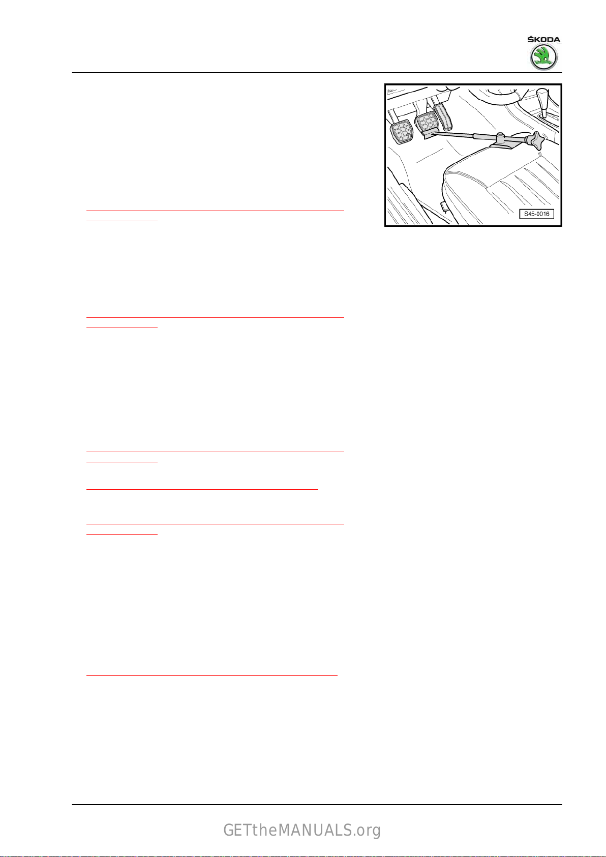
Rapid NH 2013 ➤ , Rapid NH 2014 ➤
GETtheMANUALS.org
– Position brake pedal load , e.g. -V.A.G 1869/2- .
– Fit the bleeder hose of the bleeding bottle onto the bleeder
valve and release bleeder valve.
– Press down brake pedal with brake pedal load , e.g. -V.A.G
1869/2- , at least 60 mm.
– Tighten the drain plug.
– Do not remove brake pedal load , e. g. -V.A.G 1869/2- .
– Remove screws position -6-
⇒ “2.1.1 Summary of components - rear axle brake, drum
brake”, page 52 .
– Remove brake carrier.
– Unhook hand-brake cable where applicable.
Installing
– Install brake carrier.
– Screw on screws, position -6-
⇒ “2.1.1 Summary of components - rear axle brake, drum
brake”, page 52 .
– Hook hand-brake cable where applicable.
– Install wheel hub with wheel bearing ⇒ Axles, steering; Rep.
gr. 42 .
– Screw on the brake line.
– Remove brake pedal load .
– Install brake drum.
– Insert screw position -1-
⇒ “2.1.1 Summary of components - rear axle brake, drum
brake”, page 52 .
– Bleed brake system
⇒ “6.2 Prebleeding the hydraulic system”, page 152 .
Tightening torques
♦ ⇒ “2.1.1 Summary of components - rear axle brake, drum
brake”, page 52
Brake systems - Edition 07.2017
2.6 Removing and installing wheel-brake
cylinder
Special tools and workshop equipment required
♦ Brake pedal load , e.g. -V.A.G 1869/2♦ Bleeding bottle (commercially available)
Removing
– Remove the brake shoes
⇒ “2.7.2 Removing and installing brake shoes”, page 67 .
2. Rear brakes 65
Page 70

Rapid NH 2013 ➤ , Rapid NH 2014 ➤
GETtheMANUALS.org
Brake systems - Edition 07.2017
– Insert brake pedal load, , e.g. -V.A.G 1869/2- .
– Fit
the bleeder hose of the bleeding bottle onto the vent valve
of the wheel-brake cylinder.
– Open vent valve.
– Press the brake pedal by at least 60 mm and lock with brake
pedal load , e. g. -V.A.G 1869/2- .
– Shut the vent valve once the brake fluid flowed out.
– Do not remove brake pedal load , e. g. -V.A.G 1869/2- .
– Remove brake line.
– Remove screws Pos. -4-
⇒ “2.1.2 Summary of components - drum brake”, page 54 .
– Remove wheel-brake cylinder.
Installing
– Insert the wheel-brake cylinder.
– Install screws Pos. -4-
⇒ “2.1.2 Summary of components - drum brake”, page 54 .
– Install brake line.
– Remove brake pedal load .
– Install the brake shoes
⇒ “2.7.2 Removing and installing brake shoes”, page 67 .
– Bleed brake system
⇒ “6.2 Prebleeding the hydraulic system”, page 152 .
Tightening torques
♦ ⇒ “2.1.1 Summary of components - rear axle brake, drum
brake”, page 52
♦ ⇒ “2.1.2 Summary of components - drum brake”, page 54
2.7 Removing and installing brake shoes
⇒ “2.7.1 Replacing the brake shoes of the rear brake - Mounting
instructions”, page 66
⇒ “2.7.2 Removing and installing brake shoes”, page 67
2.7.1 Replacing the brake shoes of the rear
brake - Mounting instructions
When changing the brake shoes, pay attention to the following
points:
– Check the protective collars of the wheel-brake cylinders.
Replace the wheel-brake cylinders if the protective collars are
damaged
⇒ “2.6 Removing and installing wheel-brake cylinder”, page 65 .
– Test wheel-brake cylinder for tightness ⇒ page 56 .
Replace the wheel-brake cylinder if leaking
⇒ “2.6 Removing and installing wheel-brake cylinder”, page 65 .
– Check if the pistons can be slightly pressed into the wheel-
brake cylinder.
If the pistons cannot be slightly pressed into the wheel-brake cyl‐
inder:
66 Rep. gr.46 - Brakes - mechanism
Page 71
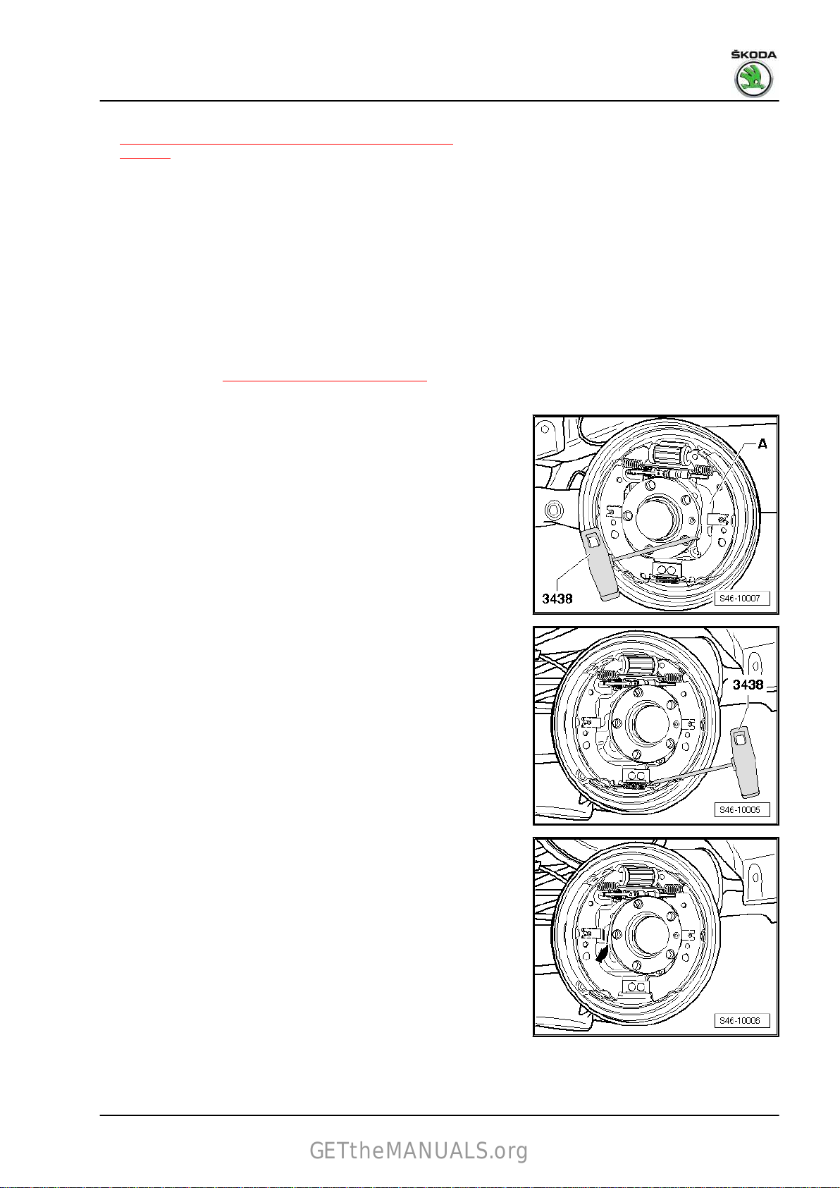
– Replace the wheel-brake cylinder
GETtheMANUALS.org
⇒ “2.6 Removing and installing wheel-brake cylinder”,
page 65 .
2.7.2 Removing and installing brake shoes
Special tools and workshop equipment required
♦ Hook - 3438♦ Assembly tool - T30114♦ Assembly pliers - T30115♦ Solid lubricant paste - G 000 650Removing
– Remove wheel.
– Resetting brake ⇒ “2.4 Resetting brake”, page 63 .
– Remove the brake drum.
– Put the handbrake lever -A- with the hook - 3438- back into
the operating position.
Rapid NH 2013 ➤ , Rapid NH 2014 ➤
Brake systems - Edition 07.2017
– Remove the bottom retractor spring with the hook - 3438- .
– Remove the securing clamp and the pin of the brake shoe
-in direction of arrow-
.
2. Rear brakes 67
Page 72

Rapid NH 2013 ➤ , Rapid NH 2014 ➤
GETtheMANUALS.org
Brake systems - Edition 07.2017
– Carefully release the brake shoe and detach the expansion
rod in direction of arrow
-B- from the brake shoe.
NOTICE
Do not cut through the rubber bowl for the wheel-brake cylinder
when handling the brake shoe.
– Detach the expansion rod in direction of arrow -A- from the
brake shoe with handbrake lever.
– Remove the top brake spring and the brake shoe.
– Unhook the hand-brake cable.
– Remove the securing clamp with the pin of the brake shoe with
handbrake lever.
– Remove brake shoe.
Installing
– Grease contact surfaces -arrows- with solid lubricant paste -
G 000 650- .
– Insert the brake shoe with handbrake lever and interlock the
securing
– Note installation position
clamp on the pin with the assembly device - T30114- .
⇒ page 55 .
68 Rep. gr.46 - Brakes - mechanism
Page 73

– Insert the top brake spring.
GETtheMANUALS.org
– Insert the pin and the fixing clamp for the brake shoe.
Rapid NH 2013 ➤ , Rapid NH 2014 ➤
Brake systems - Edition 07.2017
– Hook in the bottom retractor spring with the hook - 3438- .
– Carefully screw the expansion rod to its shortest dimension,
do not tighten.
Note
If the expansion rod is tightened too much, the self-adjuster
mechanism does no longer operate.
– Pull apart the brake shoes with assembly pliers - T30115- .
2. Rear brakes 69
Page 74
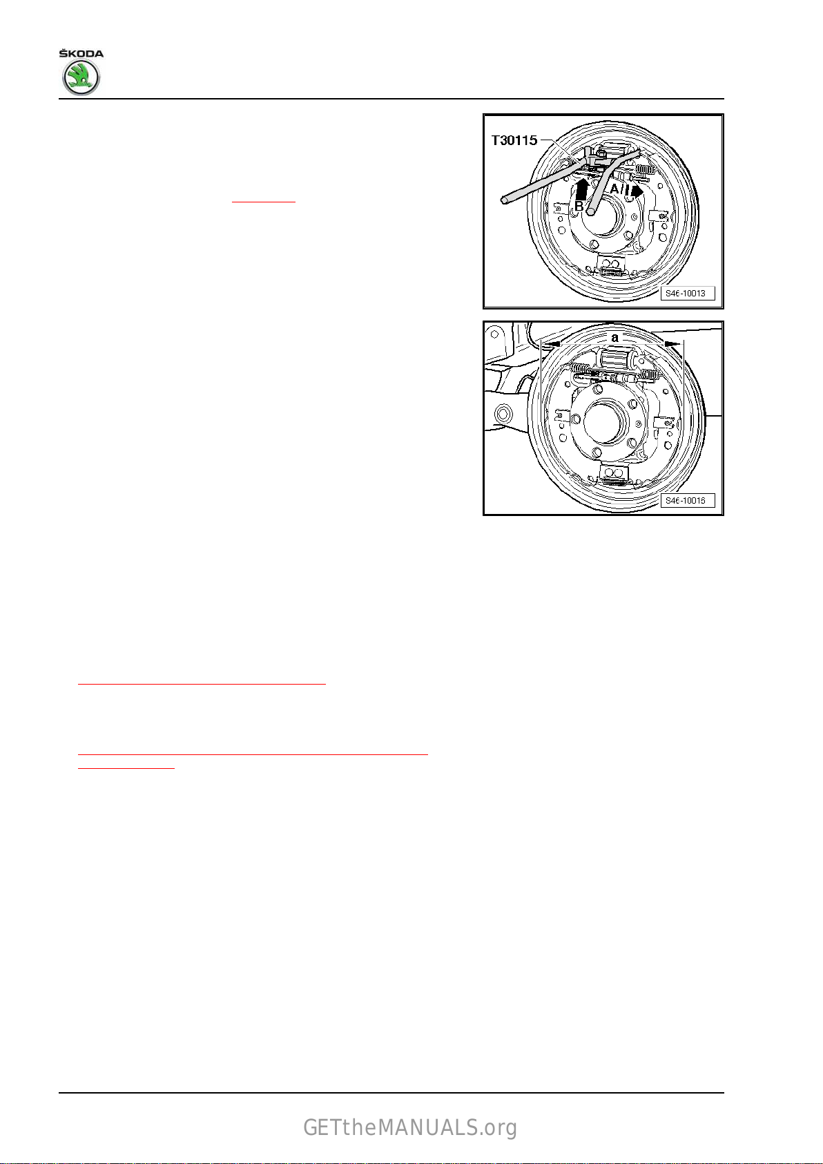
Rapid NH 2013 ➤ , Rapid NH 2014 ➤
GETtheMANUALS.org
Brake systems - Edition 07.2017
– First of all, position the expansion rod of the self-adjuster in
direction
– Insert the lever for the self-adjuster into the recess of the sec‐
ond brake shoe -arrow B-.
– Note installation position
– Repeatedly pull apart the brake shoes using the assembly pli‐
ers - T30115- , so that the self-adjuster presets the distance
from the edges of the brake shoes with lining to the dimension
-a-.
a - 227.8 mm
– Clean the centring seat of the wheel hub for the brake drum
and subsequently treat it with anti-corrosion agent - AKR 322
000- .
– Clean the centring hole of the brake drum and subsequently
treat it with anti-corrosion agent - AKR 322 000- .
of arrow -A- on the brake shoe with handbrake lever.
⇒ page 56 .
Note
The anti-corrosion agent - AKR 322 000- must not get into the
threads of the wheel screws!
– Install brake drum.
– Activate the brake pedal forcefully several times, so that the
rear brake is adjusted.
– Adjust handbrake
⇒ “3.2 Adjusting parking brake”, page 72 .
– Attach the wheel.
Tightening torques
♦ ⇒ “2.1.1 Summary of components - rear axle brake, drum
brake”, page 52
♦ Wheel bots ⇒ Wheels, tyres; Rep. gr. 44
70 Rep. gr.46 - Brakes - mechanism
Page 75

3 Handbrake
GETtheMANUALS.org
⇒ “3.1 Assembly overview - parking brake”, page 71
⇒ “3.2 Adjusting parking brake”, page 72
⇒ “3.3 Removing and installing the rear handbrake cable”,
page 74
3.1 Assembly overview - parking brake
1 - Parking brake lever
❑
Removing the centre
console ⇒ Body Work;
Rep. gr. 68
❑ Assignment ⇒ Electron‐
ic Catalogue of Original
Parts
2 - Handbrake handle
❑ Assignment ⇒ Electron‐
ic Catalogue of Original
Parts
❑ Removing and installing
⇒ page 72
3 - Compensating clamp
4 - Adjusting nut
❑
Adjusting parking brake
⇒ “3.2 Adjusting parking
brake”, page 72 .
5 - Grommet
❑
removing:
– Pull cable out of the
guide tube.
Rapid NH 2013 ➤ , Rapid NH 2014 ➤
Brake systems - Edition 07.2017
– Release grommet.
– Pull grommet from
guide tube.
❑ Installing:
Installation is carried out
in the reverse order. After
installing make sure the
grommet fits correctly in
the body recess.
6 - Right guide tube
❑ for handbrake cable
7 - Left guide tube
❑ for handbrake cable
8 - Hand-brake cable
❑ Removing and installing
9 - Handbrake control switch - F9-
❑
clipped onto hand-brake lever
❑ replace if defective
⇒ “3.3 Removing and installing the rear handbrake cable”, page 74
3. Handbrake 71
Page 76
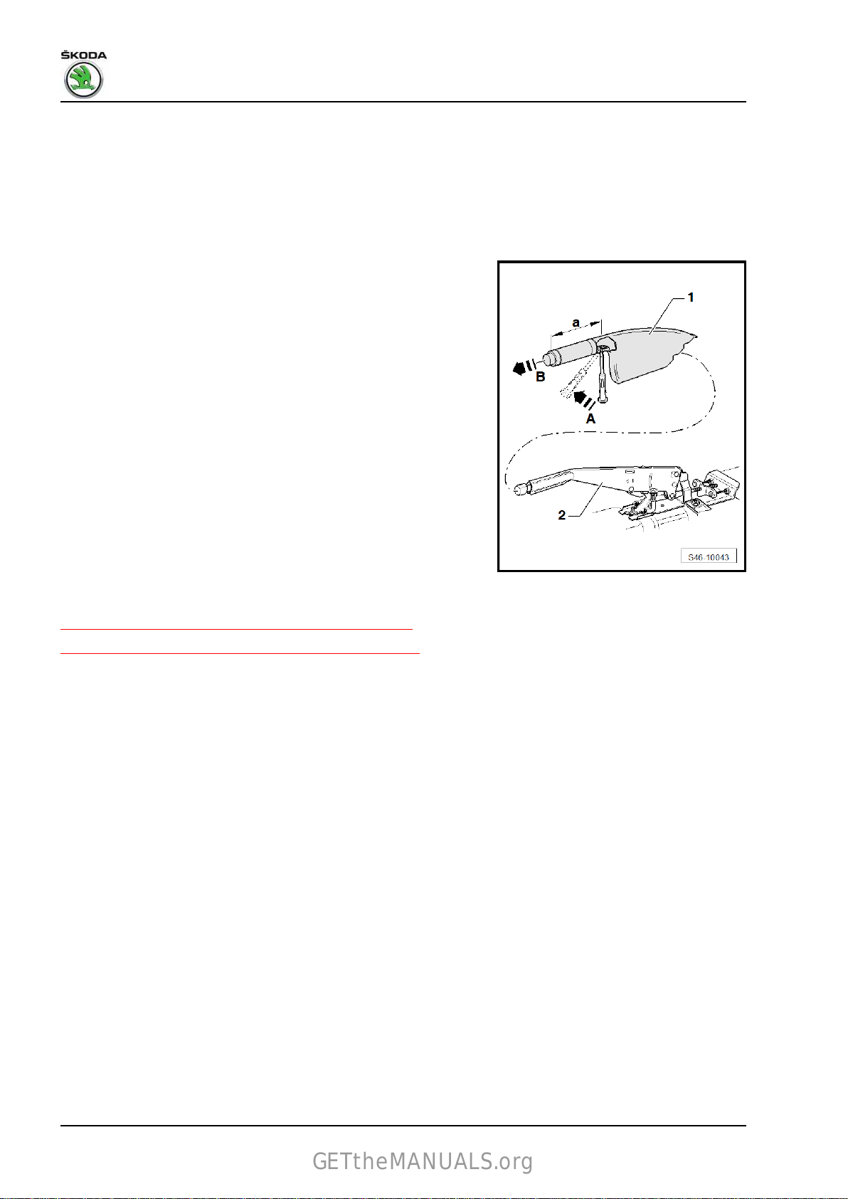
Rapid NH 2013 ➤ , Rapid NH 2014 ➤
GETtheMANUALS.org
Brake systems - Edition 07.2017
10 - Nut
❑
23 Nm
Removing and installing the handbrake lever handle
Removing
– Engage the handbrake lever -2-.
– For example, insert a cross-head screwdriver into the recess
of the handle and unlock the securing lock in
- direction of arrow A -.
– Push out the handbrake lever handle -1- in
-direction of arrow B-.
Note
On vehicles with the leather package, the recess for unlocking the
safety bar must be at a clearance -a- 97 mm from the front face
of the handle. The position is covered, which means that a thin
scriber must be used to unlock it through which the bar must be
unlocked in the same way after piercing the leather, as is the case
in vehicles with a classic handle.
Installing
– Fit the handle for handbrake lever to the parking brake lever
and press until the securing clip engages.
3.2 Adjusting parking brake
⇒ “3.2.1 Adjusting the handbrake – disc brake”, page 72
⇒ “3.2.2 Adjusting the handbrake – drum brake”, page 73
3.2.1 Adjusting the handbrake – disc brake
Note
There is no need to adjust the handbrake due to automatic
♦
adjustment of the rear brake.
♦
Resetting is only required after replacing the handbrake cable,
the brake carrier or after replacing the brake discs.
– Remove storage compartment or arm rest ⇒ Body Work; Rep.
gr. 68 .
– Release hand-brake (hand brake lever in rest position).
– Forcefully apply the foot brake at least three times.
– Pull the handbrake on and release it three times.
This sets the components into position.
– Release handbrake lever.
72 Rep. gr.46 - Brakes - mechanism
Page 77
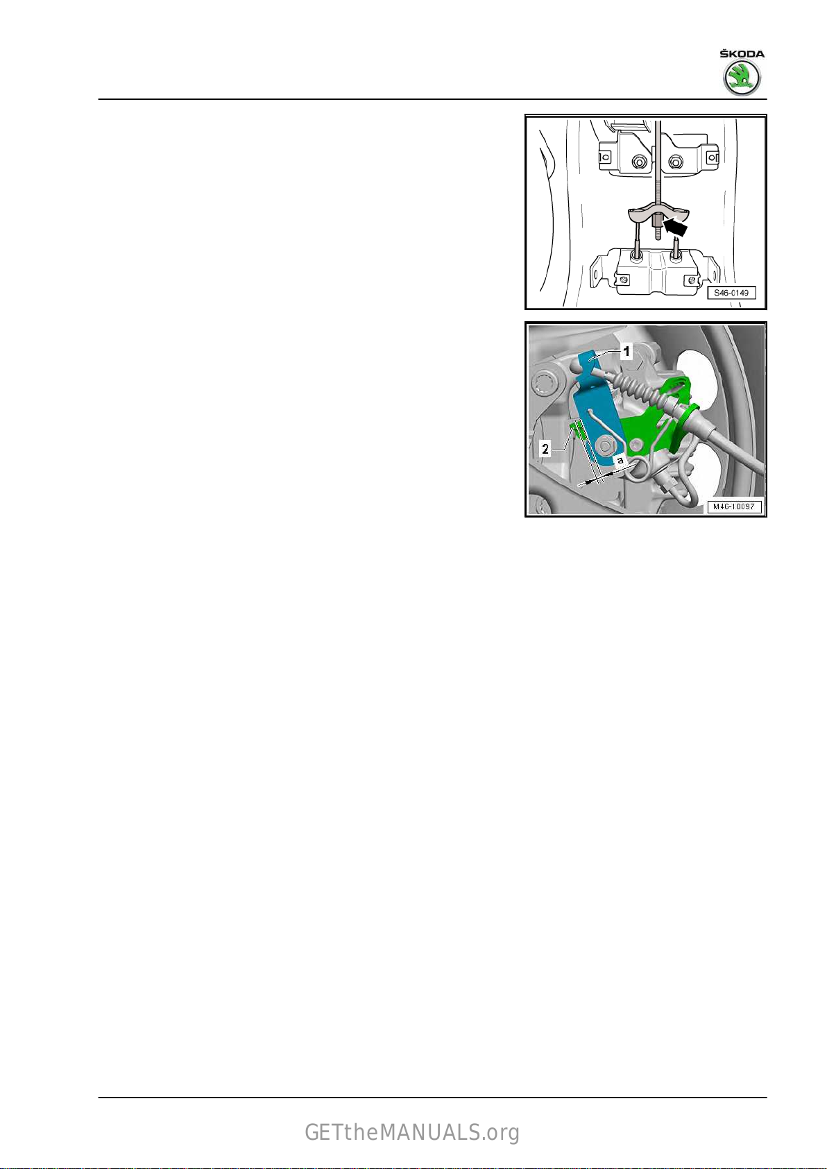
Rapid NH 2013 ➤ , Rapid NH 2014 ➤
GETtheMANUALS.org
– Tighten adjusting nut -arrow-, …
– … until the lever -1- rises and is no longer in contact -2- with
the brake calipers.
Note
The adjusting nut arrow -A- must be screwed over the end of the
tension rod (self-locking effect).
– The distance -a- to the stop -2- on the left and right brake cal‐
iper must together not exceed 1.5 mm.
– Engage and release the handbrake, and check that both
wheels spin freely; if necessary, turn back the adjustment nut
slightly.
– Install storage compartment or arm rest ⇒ Body Work; Rep.
gr. 68 .
Brake systems - Edition 07.2017
3.2.2 Adjusting the handbrake – drum brake
Note
♦
Resetting of the hand-brake is not required after resetting of
the rear brake due to automatic resetting of the rear wheelbrake.
♦
Resetting is required after replacing the hand-brake cable, the
brake carrier or the brake pads/brake shoes or brake drum.
– Remove storage compartment or arm rest ⇒ Body Work; Rep.
gr. 68 .
– Release hand-brake (hand brake lever in rest position).
– Forcefully apply the foot brake at least three times.
– Pull the handbrake on and release it three times.
This sets the components into position.
– Put the hand-brake lever into the 1st catch position (after being
in the release position).
3. Handbrake 73
Page 78

Rapid NH 2013 ➤ , Rapid NH 2014 ➤
GETtheMANUALS.org
Brake systems - Edition 07.2017
– Tighten
by hand.
The adjusting nut arrow -A- must be screwed over the end of the
tension rod (self-locking effect).
– Release hand-brake and check whether both wheels rotate
freely, if necessary release adjusting nut slightly.
– Put the hand-brake lever into the 4th catch position (after being
in the release position).
No wheel should be rotatable; tighten the adjusting nut if nec‐
essary.
– Release hand-brake and check whether both wheels rotate
freely, if necessary release adjusting nut slightly.
– Put the hand-brake lever into the 1st catch position and re‐
lease the hand-brake.
The hand brake must automatically return to the release po‐
sition below the 1st catch.
– Install storage compartment or arm rest ⇒ Body Work; Rep.
gr. 68 .
adjusting nut -arrow- until both wheels are hard to turn
Note
3.3 Removing and installing the rear hand‐
brake cable
⇒ “3.3.1 Removing and installing the rear handbrake cable, disc
brake”, page 74
⇒ “3.3.2 Removing and installing the rear handbrake cable, drum
brake”, page 76
3.3.1 Removing and installing the rear hand‐
brake cable, disc brake
Removing
– Put hand-brake back.
– Remove
gr. 68 .
– Release resetting nut -3- and unhook hand-brake cables -1-
from compensating clamp -2-.
– Remove wheel.
– Raise vehicle.
storage compartment or arm rest ⇒ Body Work; Rep.
74 Rep. gr.46 - Brakes - mechanism
Page 79

Rapid NH 2013 ➤ , Rapid NH 2014 ➤
GETtheMANUALS.org
– Unclip the hand-brake cable out of the clips on the axle body
and body -arrows-
– Push the handbrake lever in the -direction of the arrow- and
unhook the hand-brake cable.
– Release the two retaining tabs -arrows- and undo the spring
bushing
calliper.
for the handbrake cable from the holder on the brake
.
Brake systems - Edition 07.2017
– Pull hand-brake cable -2- (in -direction of arrow-) out of the
guide tube -1-.
Installing
Installation is carried out in the reverse order.
Note
When installing the hand brake cables, pay attention to the fitting
position.
Fitting position of the hand-brake cables
Note
Fitting position of the hand-brake cables is identical on vehicles
with drum or disc brake (only version with drum brake is shown).
– The hand-brake cables must be clipped in.
3. Handbrake 75
Page 80

Rapid NH 2013 ➤ , Rapid NH 2014 ➤
GETtheMANUALS.org
Brake systems - Edition 07.2017
– The
Before setting the handbrake, slightly pretension the handbrake
cable with the adjustment nut on the compensator.
– Adjusting parking brake
Tightening torques
♦ Wheel bots ⇒ Wheels, tyres; Rep. gr. 44
clamping ring -arrow A- at the hand-brake cable must rest
in the centre of the clip -arrow B-.
Note
⇒ “3.2 Adjusting parking brake”, page 72 .
3.3.2 Removing and installing the rear hand‐
brake cable, drum brake
Removing
– Put hand-brake back.
– Remove
gr. 68 .
– Release resetting nut -3- and unhook hand-brake cables -1-
from compensating clamp -2-.
– Remove wheel.
– Raise vehicle.
storage compartment or arm rest ⇒ Body Work; Rep.
– Unclip the hand-brake cable out of the clips on the axle body
and body -arrows– Remove the brake drum.
– Unhook the hand-brake cable at the hand-brake lever.
– Pull hand-brake cable out of brake carrier.
.
76 Rep. gr.46 - Brakes - mechanism
Page 81

Rapid NH 2013 ➤ , Rapid NH 2014 ➤
GETtheMANUALS.org
– Pull hand-brake cable -2- in -the direction of the arrow- out of
the guide tube -1-.
Installing
Installation is carried out in the reverse order.
Note
When installing the hand brake cables, pay attention to the fitting
position.
Fitting position of the hand-brake cables
– The hand-brake cables must be clipped in.
Brake systems - Edition 07.2017
– The
clamping ring -arrow A- at the hand-brake cable must rest
in the centre of the clip -arrow B-.
Note
Before setting the hand-brake, slightly pretension the hand-brake
cable with the adjusting nut at the compensation clamp.
– Adjusting parking brake
⇒ “3.2 Adjusting parking brake”, page 72 .
Tightening torques
♦ Wheel bots ⇒ Wheels, tyres; Rep. gr. 44
3. Handbrake 77
Page 82

Rapid NH 2013 ➤ , Rapid NH 2014 ➤
GETtheMANUALS.org
Brake systems - Edition 07.2017
4 Brake pedal
⇒ “4.1 Assembly overview - brake pedal”, page 78
⇒ “4.2 Removing and installing bearing bracket”, page 84
⇒ “4.3 Separating brake pedal from brake servo”, page 87
⇒ “4.4 Clipping the brake pedal onto the brake servo unit”,
page 88
⇒ “4.5 Removing and installing brake pedal”, page 88
4.1 Assembly overview - brake pedal
⇒ “4.1.1 Summary of components - brake pedal, left-hand drive
vehicles up to 10/2013”, page 78
⇒ “4.1.2 Summary of components - brake pedal, left-hand drive
vehicles from 11/2013”, page 79
⇒ “4.1.3 Summary of components - brake pedal, right-hand drive
vehicles up to 10/2013”, page 81
⇒ “4.1.4 Summary of components - brake pedal, right-hand drive
vehicles from 11/2013”, page 82
4.1.1 Summary of components - brake pedal, left-hand drive vehicles up to 10/2013
WARNING
The travel of the brake pedal must not be shortened by addi‐
tional foot mats.
Note
♦
Grease all bearing surfaces with polycarbamide grease - G 052 142 A2- before assembly.
♦
Do not grease the bearing bolt. The bearing bolt must remain dry.
♦
The brake light switch - F- and brake pedal switch - F47- are located on the master brake cylinder.
78 Rep. gr.46 - Brakes - mechanism
Page 83

1 - Bearing bracket
GETtheMANUALS.org
❑
for foot controls
❑ Removing and installing
⇒ “4.2.1 Removing and
installing bearing brack‐
et, left-hand drive vehi‐
cles from 10/2013”,
page 84
2 - Nut
❑
self-locking
❑ Replace after removal
❑ 25 Nm
3 - Bushing
4 - Brake pedal
❑ Removing and installing
⇒ “4.5.1 Removing and
installing brake pedal,
left-hand drive vehicles
up to 10/2013”,
page 88
5 - Cap
6 - Bearing shell
7 - Retaining clip
❑ for
8 - Bearing shaft
❑ must only be fitted once,
9 - Bushing
the spherical head of
the brake servo push
rod
because the tabs break
off when removing
Rapid NH 2013 ➤ , Rapid NH 2014 ➤
Brake systems - Edition 07.2017
4.1.2 Summary of components - brake pedal, left-hand drive vehicles from 11/2013
WARNING
The travel of the brake pedal must not be shortened by addi‐
tional foot mats.
4. Brake pedal 79
Page 84

Rapid NH 2013 ➤ , Rapid NH 2014 ➤
GETtheMANUALS.org
Brake systems - Edition 07.2017
Note
♦
Grease all bearing surfaces with polycarbamide grease - G 052 142 A2- before assembly.
♦
Do not grease the bearing bolt. The bearing bolt must remain dry.
♦
The brake light switch - F- and brake pedal switch - F47- are located on the master brake cylinder.
1 - Bearing bracket
❑ with brake and acceler‐
ator pedal
Note
Brake pedal cannot be replaced
♦
individually.
♦
Turbocharger can only be re‐
placed completely with exhaust
manifold
⇒ “4.2.2 Removing and installing
bearing bracket, left-hand drive
vehicles from 11/2013”,
page 84 .
❑ Separating brake pedal
from brake servo
⇒ “4.3 Separating brake
pedal from brake servo”,
page 87
❑ Clipping the brake pedal
onto the brake servo
⇒ “4.4 Clipping the
brake pedal onto the
brake servo unit”,
page 88
❑ Removing and installing
⇒ “4.2.2 Removing and
installing bearing brack‐
et, left-hand drive vehi‐
cles from 11/2013”,
page 84
2 - Nut
❑ self-locking
❑ Replace after removal
❑ 25 Nm
3 - Fixing clamp
❑ not replaceable individually
4 - Cap
5 - Brake pedal
Note
♦
Brake pedal cannot be replaced
individually.
80 Rep. gr.46 - Brakes - mechanism
Page 85

♦
GETtheMANUALS.org
Turbocharger can only be re‐
placed completely with exhaust
manifold
⇒ “4.2.2 Removing and installing
bearing bracket, left-hand drive
vehicles from 11/2013”,
page 84 .
Rapid NH 2013 ➤ , Rapid NH 2014 ➤
Brake systems - Edition 07.2017
❑ Separating brake pedal from brake servo
Clipping the brake pedal onto the brake servo
❑
⇒ “4.4 Clipping the brake pedal onto the brake servo unit”, page 88
6 - Bearing shaft
not replaceable individually
❑
7 - Retaining clip
❑ for the spherical head of the brake servo push rod
❑ Separating brake pedal from brake servo
❑
Clipping the brake pedal onto the brake servo
⇒ “4.4 Clipping the brake pedal onto the brake servo unit”, page 88
8 - Bearing shell
9 - Bushing
⇒ “4.3 Separating brake pedal from brake servo”, page 87
⇒ “4.3 Separating brake pedal from brake servo”, page 87
4.1.3 Summary of components - brake pedal, right-hand drive vehicles up to
10/2013
WARNING
The travel of the brake pedal must not be shortened by addi‐
tional foot mats.
4. Brake pedal 81
Page 86

Rapid NH 2013 ➤ , Rapid NH 2014 ➤
GETtheMANUALS.org
Brake systems - Edition 07.2017
Note
♦
Grease all bearing surfaces with polycarbamide grease - G 052 142 A2- before assembly.
♦
Do not grease the bearing bolt. The bearing bolt must remain dry.
♦
The brake light switch - F- and brake pedal switch - F47- are located on the master brake cylinder.
1 - Screw
2 - Bushing
3 - Brake pedal
❑ Removing and installing
⇒ “4.5.2 Removing and
installing brake pedal,
right-hand drive vehi‐
cles up to 10/2013”,
page 89
4 - Bearing bracket
for foot controls
❑
❑ Removing and installing
⇒ “4.2.3 Removing and
installing bearing brack‐
et, right-hand drive vehi‐
cles up to 10/2013”,
page 85
5 - Nut
self-locking
❑
❑ Replace after removal
❑ 25 Nm
6 - Nut
❑ self-locking
❑ Replace after removal
❑ 25 Nm
7 - Cap
8 - Bearing shell
9 - Retaining clip
❑ for the spherical head of
the brake servo push
rod
4.1.4 Summary of components - brake pedal, right-hand drive vehicles from
11/2013
WARNING
The travel of the brake pedal must not be shortened by addi‐
tional foot mats.
82 Rep. gr.46 - Brakes - mechanism
Page 87

Rapid NH 2013 ➤ , Rapid NH 2014 ➤
GETtheMANUALS.org
Brake systems - Edition 07.2017
Note
♦
Grease all bearing surfaces with polycarbamide grease - G 052 142 A2- before assembly.
♦
Do not grease the bearing bolt. The bearing bolt must remain dry.
♦
The brake light switch - F- and brake pedal switch - F47- are located on the master brake cylinder.
1 - Partition panel
2 - Screw
❑ remove from engine
compartment
❑ 20 Nm
3 - Bearing bracket
❑ with brake and acceler‐
ator pedal
Note
♦
Brake pedal cannot be replaced
individually.
♦
Turbocharger can only be re‐
placed completely with exhaust
manifold
⇒ “4.2.4 Removing and installing
bearing bracket, right-hand drive
vehicles from 11/2013”,
page 86 .
❑ Separating brake pedal
from brake servo
⇒ “4.3 Separating brake
pedal from brake servo”,
page 87
❑ Clipping the brake pedal
onto the brake servo
⇒ “4.4 Clipping the
brake pedal onto the
brake servo unit”,
page 88
❑ Removing and installing
⇒ “4.2.4 Removing and
installing bearing brack‐
et, right-hand drive vehi‐
cles from 11/2013”,
page 86
4 - Nut
❑ self-locking
❑ 25 Nm
5 - Nut
❑ self-locking
❑ Replace after removal
❑ 25 Nm
6 - Cap
7 - Retaining clip
❑ for the spherical head of the brake servo push rod
❑ Separating brake pedal from brake servo ⇒ “4.3 Separating brake pedal from brake servo”, page 87
4. Brake pedal 83
Page 88

Rapid NH 2013 ➤ , Rapid NH 2014 ➤
GETtheMANUALS.org
Brake systems - Edition 07.2017
❑ Clipping the brake pedal onto the brake servo
⇒ “4.4 Clipping the brake pedal onto the brake servo unit”, page 88
4.2 Removing and installing bearing bracket
⇒ “4.2.1 Removing and installing bearing bracket, left-hand drive
vehicles from 10/2013”, page 84
⇒ “4.2.2 Removing and installing bearing bracket, left-hand drive
vehicles from 11/2013”, page 84
⇒ “4.2.3 Removing and installing bearing bracket, right-hand drive
vehicles up to 10/2013”, page 85
⇒ “4.2.4 Removing and installing bearing bracket, right-hand drive
vehicles from 11/2013”, page 86
4.2.1 Removing and installing bearing brack‐
et, left-hand drive vehicles from 10/2013
Removing
– Removing the left footwell vent ⇒ Heating, Air Conditioning;
Rep. gr. 87 .
– Separating the brake pedal from the brake servo unit
⇒ “4.3 Separating brake pedal from brake servo”, page 87 .
– Disconnect the plug connection from the accelerator pedal
position sender.
– Remove gas pedal ⇒ Engine; Rep. gr. 20 .
– Remove the nuts -arrows- for the bearing bracket.
– Remove bracket.
Installing
Installation is carried out in the reverse order.
Tightening torques
♦ ⇒ “4.1.1 Summary of components - brake pedal, left-hand
drive vehicles up to 10/2013”, page 78
4.2.2 Removing and installing bearing brack‐
left-hand drive vehicles from 11/2013
et,
Removing
– Remove brake servo unit
⇒ “3.6 Removing and installing brake servo”, page 114 .
– Remove cover of fuse box in -direction of arrow-.
– Unscrew screws for fuse box and place box to one side ⇒
Electrical System; Rep. gr. 97 .
– Disconnect the plug connection from the accelerator pedal
position sender.
– Remove gas pedal ⇒ Engine; Rep. gr. 20 .
84 Rep. gr.46 - Brakes - mechanism
Page 89

Rapid NH 2013 ➤ , Rapid NH 2014 ➤
GETtheMANUALS.org
– Unscrew bolt -arrow- and detach universal joint -1- (in
-direction
gear.
– Place universal joint with steering column to one side.
– Remove the nuts -arrows- from the bearing bracket.
– Remove foot controls.
Installing
Installation is carried out in the reverse order; pay attention to the
following points:
– Clipping the brake pedal onto the brake servo
⇒ “4.4 Clipping the brake pedal onto the brake servo unit”,
page 88
Tightening torques
♦ ⇒ “4.1.2 Summary of components - brake pedal, left-hand
drive vehicles from 11/2013”, page 79
♦ Accelerator pedal ⇒ Engine; Rep. gr. 20
♦ Footwell vent ⇒ Heating, Air Conditioning; Rep. gr. 87
of arrow-) from the input shaft of the power-steering
Brake systems - Edition 07.2017
4.2.3 Removing and installing bearing brack‐
et, right-hand drive vehicles up to
10/2013
Removing
– Remove
gr. 80 .
– Disconnect the plug connection from the accelerator pedal
position sender.
– Unscrews nuts -arrow A- and -arrow B-.
– Remove the foot rest -1- and the steering column trim panel
-2-.
– Separating the brake pedal from the brake servo unit
⇒ “4.3 Separating brake pedal from brake servo”, page 87 .
right footwell vent ⇒ Heating, Air Conditioning; Rep.
4. Brake pedal 85
Page 90
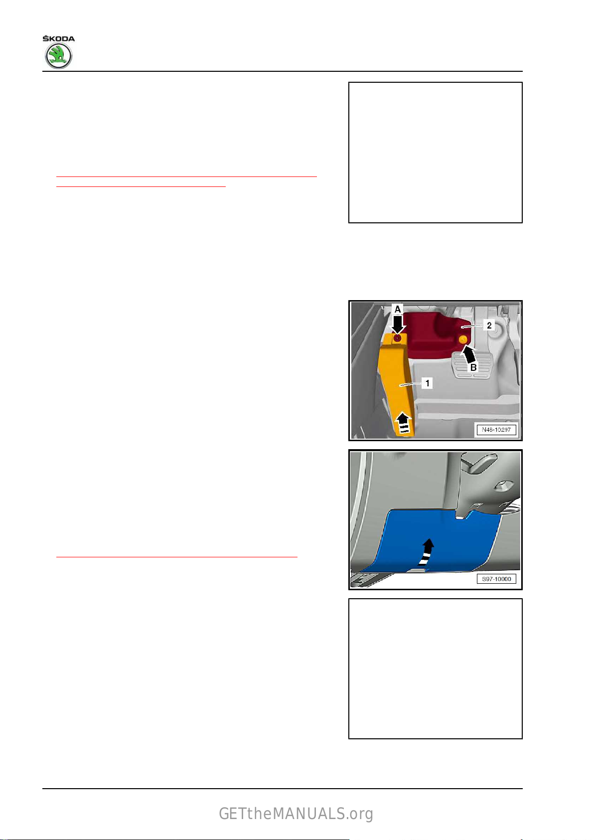
Rapid NH 2013 ➤ , Rapid NH 2014 ➤
GETtheMANUALS.org
Brake systems - Edition 07.2017
– Remove the nuts -arrows- for the bearing bracket.
– Remove bracket.
Installing
Installation is carried out in the reverse order.
Tightening torques
♦ ⇒ “4.1.3 Summary of components - brake pedal, right-hand
drive vehicles up to 10/2013”, page 81
4.2.4 Removing and installing bearing brack‐
et, right-hand drive vehicles from
11/2013
Removing
– Unscrews nuts -arrow A- and -arrow B-.
– Remove the foot rest -1- and the steering column trim panel
-2-.
– Removing the left footwell vent on the driver side ⇒ Heating,
Air Conditioning; Rep. gr. 87 .
– Remove cover of fuse box in -direction of arrow-.
– Unscrew screws for fuse box and place box to one side ⇒
Electrical System; Rep. gr. 97 .
– Disconnect the plug connection from the accelerator pedal
position sender.
– Remove gas pedal ⇒ Engine; Rep. gr. 20 .
– Remove brake servo unit
⇒ “3.6 Removing and installing brake servo”, page 114 .
– Unscrew bolt -arrow- and detach universal joint -1- (in
-direction
gear.
– Place universal joint with steering column to one side.
of arrow-) from the input shaft of the power-steering
86 Rep. gr.46 - Brakes - mechanism
Page 91

Rapid NH 2013 ➤ , Rapid NH 2014 ➤
GETtheMANUALS.org
– Remove the nuts arrows -A- for the bearing bracket.
– Remove the screw -arrow B-, which secures the foot controls
from the engine compartment.
– Remove foot controls.
Installing
Installation is carried out in the reverse order; pay attention to the
following points:
– Clipping the brake pedal onto the brake servo
⇒ “4.4 Clipping the brake pedal onto the brake servo unit”,
page 88
Tightening torques
♦ ⇒ “4.1.4 Summary of components - brake pedal, right-hand
drive vehicles from 11/2013”, page 82
♦ Accelerator pedal ⇒ Engine; Rep. gr. 20
♦ Footwell vent ⇒ Heating, Air Conditioning; Rep. gr. 87
4.3 Separating brake pedal from brake ser‐
vo
Brake systems - Edition 07.2017
Special tools and workshop equipment required
♦ Release tool - T10159A- or -T10159B– Press the brake pedal towards the brake servo unit and hold
it in position.
2 - Plunger rod
3 - Retaining lugs
– Insert release tool - T10159A- or -T10159B- and pull it in the
direction of the driver's seat while counterholding the brake
pedal (the pedal must not move backwards during this oper‐
ation). This pushes the retaining lugs
ball head of the push rod -2-.
The fig. shows the separation of the brake pedal from the brake
servo unit with the foot controls removed for clarity.
– Pull release tool - T10159A- or -T10159B- and brake pedal
together towards the driver's seat. (This causes the brake
pedal to be drawn off the ball head of the push rod).
-3- of the mount off the
4. Brake pedal 87
Page 92
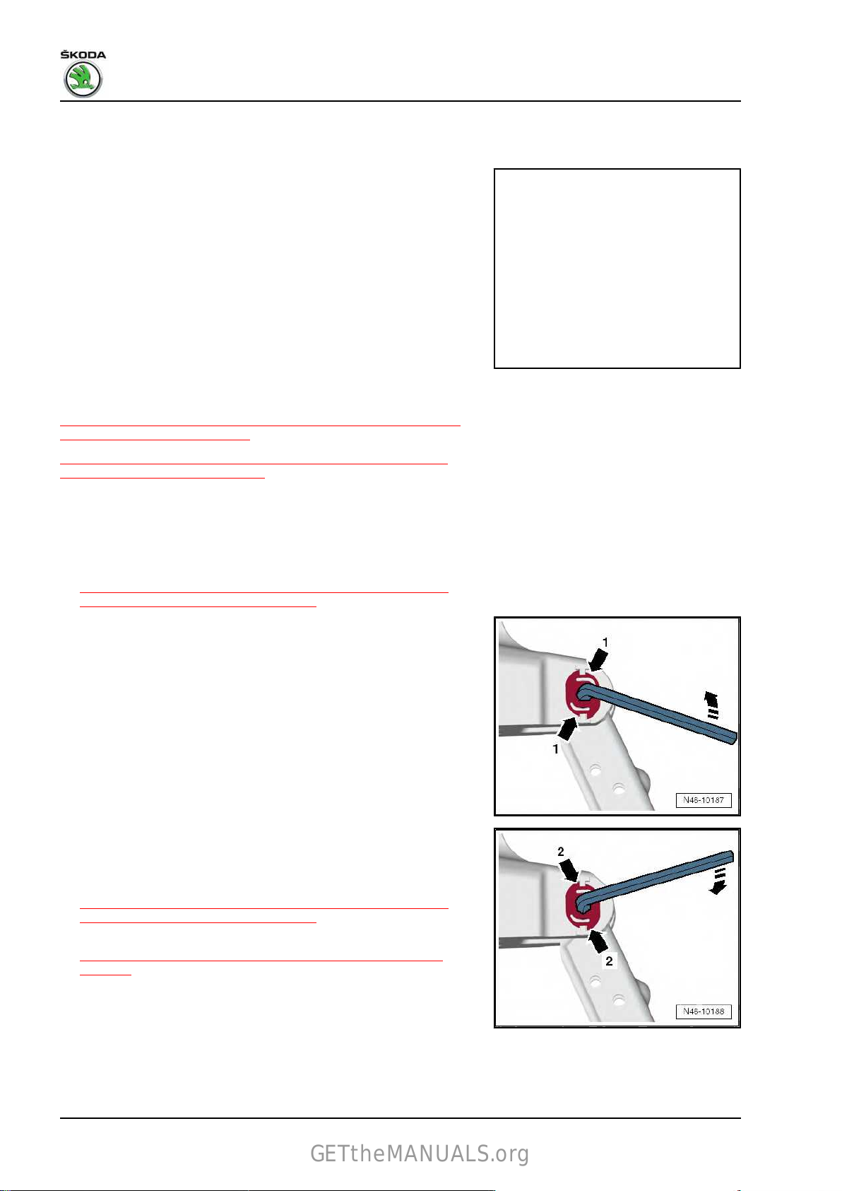
Rapid NH 2013 ➤ , Rapid NH 2014 ➤
GETtheMANUALS.org
Brake systems - Edition 07.2017
4.4 Clipping the brake pedal onto the brake servo unit
– Hold ball head of push rod in front of mount and push brake
pedal in direction of brake servo, so that the ball head clicks
into place.
– Check that it is correctly locked in place by briefly pulling on
the brake pedal.
4.5 Removing and installing brake pedal
⇒ “4.5.1 Removing and installing brake pedal, left-hand drive ve‐
hicles up to 10/2013”, page 88
⇒ “4.5.2 Removing and installing brake pedal, right-hand drive
vehicles up to 10/2013”, page 89
4.5.1 Removing and installing brake pedal, left-hand drive vehicles up to 10/2013
Removing
– Removing bracket
⇒ “4.2.1 Removing and installing bearing bracket, left-hand
drive vehicles from 10/2013”, page 84 .
– Turn the bearing axle to the left in -direction of arrow- using a
10 mm socket wrench, while doing so the tabs break off
-arrows 1-.
– Pull out bearing bolt.
– Remove brake pedal.
Installing
Installation is performed in the reverse order; pay attention to the
following points:
– Insert the bearing axle and turn clockwise in
-direction
-arrows 2- rest against the stop.
– Installing bracket
⇒ “4.2.1 Removing and installing bearing bracket, left-hand
drive vehicles from 10/2013”, page 84 .
– Clip the brake pedal onto the brake servo
⇒ “4.4 Clipping the brake pedal onto the brake servo unit”,
page 88 .
of arrow- using a 10 mm socket wrench until the tabs
88 Rep. gr.46 - Brakes - mechanism
Page 93
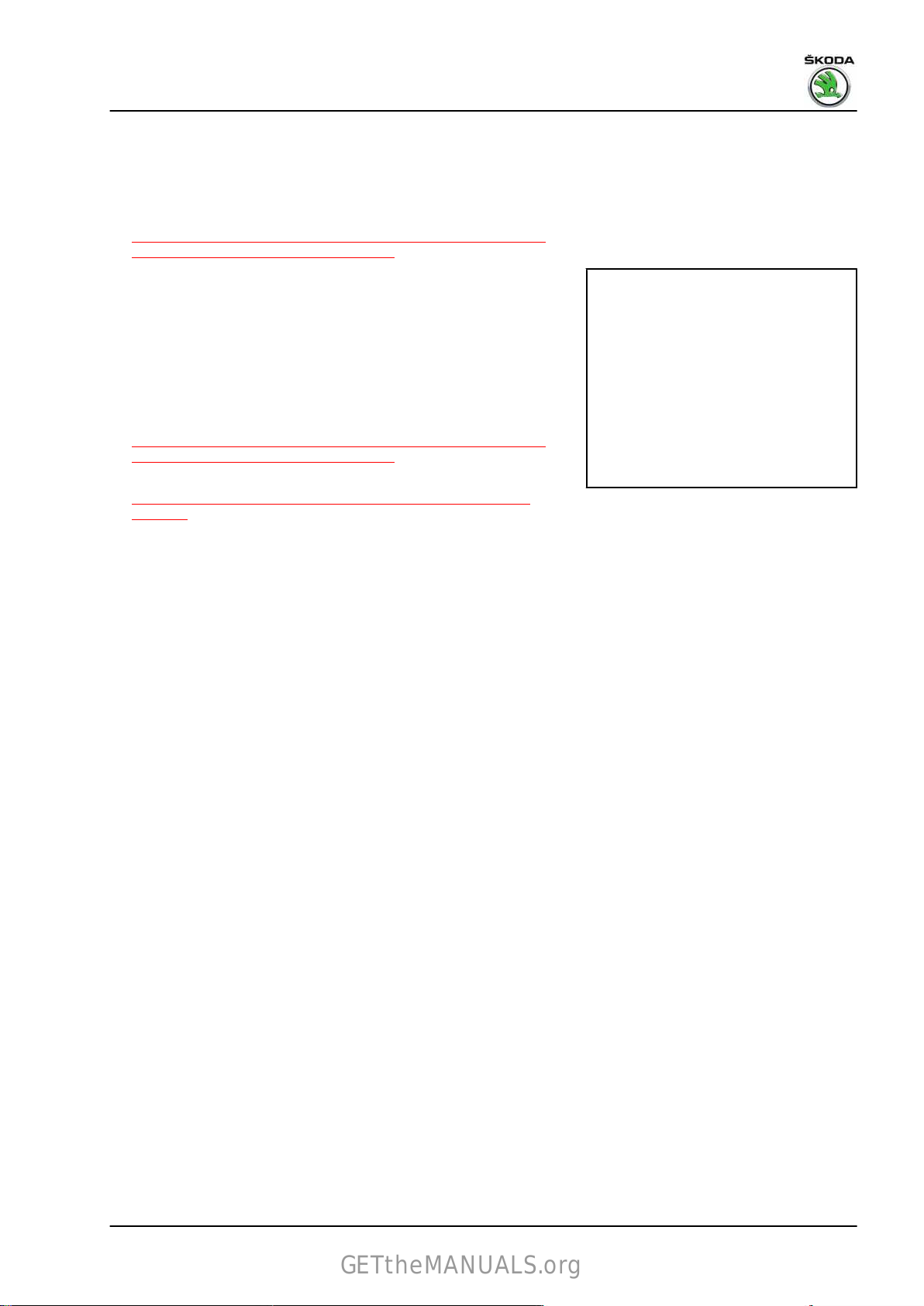
Rapid NH 2013 ➤ , Rapid NH 2014 ➤
GETtheMANUALS.org
4.5.2 Removing and installing brake pedal, right-hand drive vehicles up to 10/2013
Removing
– Removing bracket
⇒ “4.2.3 Removing and installing bearing bracket, right-hand
drive vehicles up to 10/2013”, page 85 .
– Remove nut - 2 -.
– Release screw -1-.
– Remove brake pedal.
Installing
Installation is performed in the reverse order; pay attention to the
following points:
– Installing bracket
⇒ “4.2.3 Removing and installing bearing bracket, right-hand
drive vehicles up to 10/2013”, page 85 .
– Clip the brake pedal onto the brake servo
⇒ “4.4 Clipping the brake pedal onto the brake servo unit”,
page 88 .
Brake systems - Edition 07.2017
4. Brake pedal 89
Page 94

Rapid NH 2013 ➤ , Rapid NH 2014 ➤
GETtheMANUALS.org
Brake systems - Edition 07.2017
47 – Brakes - hydraulics
1 Front brake calipers
⇒ “1.1 Summary of components - front brake caliper”, page 90
⇒ “1.2 Removing and installing brake caliper piston”, page 93
1.1 Summary of components - front brake caliper
⇒ “1.1.1 Exploded view – front brake caliper - brake FS III”, page
90
⇒ “1.1.2 Exploded view – front brake caliper - brake FN3”,
page 92
1.1.1 Exploded view – front brake caliper - brake FS III
Note
♦
Install the complete repair set when undertaking repairs.
♦
Use only methylated spirit for cleaning.
♦
Thinly coat brake cylinder, piston and gasket ring with lithium grease - G 052 150 A2- .
90 Rep. gr.47 - Brakes - hydraulics
Page 95
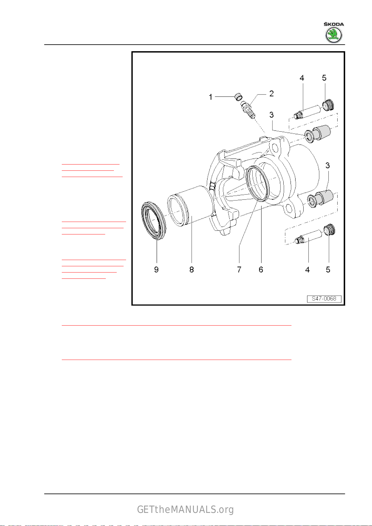
Rapid NH 2013 ➤ , Rapid NH 2014 ➤
GETtheMANUALS.org
Brake systems - Edition 07.2017
1 - Dust cap
❑
place on the vent valve
2 - Vent valve
❑ thinly coat thread with
lithium grease - G 052
150 A2- before screwing
in
❑ 10 Nm
3 - Bushing
❑ insert into the brake cal‐
iper housing
4 - Guide bolt
❑ Tightening torque
⇒ “1.1.1 Summary of
components - front
brake FS-III”, page 38
5 - Cover caps
❑
insert in bushing
6 - Brake caliper
❑ Removing and installing
⇒ “1.3.1 Removing and
installing brake caliper
FS-III”, page 46
7 - Sealing ring
❑ Removing
⇒ “1.2.1 Removing and
installing brake caliper
piston of front FS-III
brake”, page 93
❑
before installing, thinly
coat piston with lithium
grease - G 052 150 A2-
8 - Piston
❑ Removing and installing
⇒ “1.2.1 Removing and installing brake caliper piston of front FS-III brake”, page 93
❑
before installing, thinly coat piston with lithium grease - G 052 150 A2-
9 - Collar
❑ Removing and installing
⇒ “1.2.1 Removing and installing brake caliper piston of front FS-III brake”, page 93
❑
do not damage when inserting the piston
and installing
1. Front brake calipers 91
Page 96

Rapid NH 2013 ➤ , Rapid NH 2014 ➤
GETtheMANUALS.org
Brake systems - Edition 07.2017
1.1.2 Exploded view – front brake caliper - brake FN3
Note
♦
Install the complete repair set when undertaking repairs.
♦
Use only methylated spirit for cleaning.
♦
Thinly coat brake cylinder, piston and gasket ring with lithium grease - G 052 150 A2- .
1 - Cover caps
❑ insert in bushing
2 - Guide bolt
❑ Tightening torque
⇒ “1.1.2 Summary of
components - front
brake FN3”, page 40
3 - Bushing
❑ insert
4 - Dust cap
❑ place on the vent valve
5 - Vent valve
❑ thinly coat thread with
❑ 10 Nm
6 - Brake caliper
❑ Removing and installing
7 - Brake carrier
❑ crewed
8 - Spring
❑ insert with both ends in‐
9 - Sealing ring
❑ Removing and installing
❑
10 - Piston
❑ Removing and installing
❑
11 - Boot
❑ Removing and installing
❑
into the brake cal‐
iper housing
lithium grease G 052 150 A2- before
screwing in
⇒ “1.3.2 Removing and
installing brake caliper
FN3”, page 49
to the brake cal‐
iper
to the bores in the brake
caliper
⇒ “1.2.2 Removing and installing piston of brake caliper FN3”, page 94
First thinly coat piston with lithium grease - G 052 150 A2-
⇒ “1.2.2 Removing and installing piston of brake caliper FN3”, page 94
First thinly coat piston with lithium grease - G 052 150 A2-
⇒ “1.2.2 Removing and installing piston of brake caliper FN3”, page 94
do not damage when inserting the piston
92 Rep. gr.47 - Brakes - hydraulics
Page 97

Rapid NH 2013 ➤ , Rapid NH 2014 ➤
GETtheMANUALS.org
1.2 Removing and installing brake caliper piston
⇒ “1.2.1 Removing and installing brake caliper piston of front FSIII brake”, page 93
⇒ “1.2.2 Removing and installing piston of brake caliper FN3”,
page 94
1.2.1 Removing and installing brake caliper piston of front FS-III brake
Special tools and workshop equipment required
♦ Piston jig - T10145♦ Plastic wedge - 3409♦ Grease - G 052 150 A2Removing
– Remove brake caliper
⇒ “1.3.1 Removing and installing brake caliper FS-III”,
page 46 .
– Insert
– Press the piston out of the brake caliper housing using com‐
wooden plate to avoid damaging the piston as it is being
pressed out.
pressed air -arrow-.
Brake systems - Edition 07.2017
Note
Make sure that the cylinder surface is not damaged when remov‐
ing the gasket ring.
– Remove gasket ring with disassembly wedge - 3409- .
Installing
Note
♦
Always install the complete repair kit when repairing the brake
calliper.
♦
Use only methylated spirits for cleaning the brake.
♦
New brake calipers are filled with brake fluid and are pre-bled.
♦
It is absolutely necessary, if repairs are being undertaken, to
pre-bleed the brake calipers before installing them in the ve‐
hicle (without brake pads) ⇒ page 94 .
– Clean piston and gasket ring with white spirits and dry off.
– Before installing the piston and sealing ring in the brake cali‐
per, thinly coat with lithium grease - G 052 150 A2- .
– Insert new gasket ring in the groove of the brake caliper.
1. Front brake calipers 93
Page 98

Rapid NH 2013 ➤ , Rapid NH 2014 ➤
GETtheMANUALS.org
Brake systems - Edition 07.2017
– Position the protective cap with the outer sealing lip on the
piston.
– Insert inner sealing lip of the protective cap with disassembly
wedge - 3409- in the groove of the cylinder.
To do so hold the piston with the hand.
– Press
The outer sealing lip of the protective cap will clip into the piston
groove.
Pre-bleeding the brake caliper
Set up brake caliper for pre-bleeding as shown in the fig.
– Open vent valve -arrow A-.
– Using a commercially available ventilation reservoir pour in
– Close vent valve.
the piston with the piston jig - T10145- -1- into the brake
caliper.
brake fluid until bubble-free brake fluid drips out of the threa‐
ded bore (brake hose connection)
-arrow B-.
1.2.2 Removing and installing piston of brake caliper FN3
Special tools and workshop equipment required
♦ Disassembly wedge - 3409♦ Piston jig - T10145♦ Assembly tool - T10146/6-
94 Rep. gr.47 - Brakes - hydraulics
Page 99

♦ Grease - G 052 150 A2-
GETtheMANUALS.org
Removing
– Removing brake calliper
⇒ “1.3.2 Removing and installing brake caliper FN3”,
page 49
Rapid NH 2013 ➤ , Rapid NH 2014 ➤
Brake systems - Edition 07.2017
– Insert
– Press the piston out of the brake caliper housing using com‐
– Lever
wooden plate to avoid damaging the piston as it is being
pressed out.
pressed air -arrow-.
off protective cap with disassembly wedge - 3409- from
the brake caliper.
– Remove gasket ring with disassembly wedge - 3409- .
Note
When removing, make sure that the cylinder surface is not dam‐
aged.
Installing
Note
Always install the complete repair kit when repairing the brake
♦
calliper.
♦
Use only methylated spirits for cleaning the brake.
♦
New brake calipers are filled with brake fluid and are pre-bled.
♦
It is absolutely necessary, if repairs are being undertaken, to
pre-bleed the brake calipers before installing them in the ve‐
hicle (without brake pads) ⇒ page 97 .
– Clean piston and gasket ring with white spirits and dry off.
– Before inserting the piston and gasket ring, thinly coat with
lithium grease - G 052 150 A2- .
– Insert sealing ring into the brake caliper.
1. Front brake calipers 95
Page 100

Rapid NH 2013 ➤ , Rapid NH 2014 ➤
GETtheMANUALS.org
Brake systems - Edition 07.2017
– Position the protective cap -A- on the assembly tool -
T10146/6- -1-.
– Press the protective cap with the assembly tool -T10146/6-
-1- and the piston resetting jig -T10145- -2- onto the brake
caliper so that this lies in contact all around the brake caliper.
– Check fitting of the protective cap.
Note
The protective cap should no longer be removable by hand from
the brake caliper.
– Press
Do not tilt the piston, in order to avoid damage to the protective
cap.
– Blow up the protective cap with compressed air (max. 0.3
the pistons lightly onto the protective cap and lock in this
position, e.g. with Disassembly wedge -3409- -2-.
Note
MPa) -1-. At the same time the protective cap jumps onto the
piston.
96 Rep. gr.47 - Brakes - hydraulics
 Loading...