

SKODA Fabia II 2007, Fabia II 2009, Fabia II 2011, Rapid 2011, Rapid India 2011 Workshop Manual
...
Service
Workshop Manual
Fabia II 2007 ➤ , Fabia II 2009 ➤ ,
F
Rapid India 2011 ➤ , Rapid NH 2013 ➤ ,
Roomster 2006 ➤
abia II 2011 ➤ , Rapid 2011 ➤ ,
Gearbox 02R
Edition 08.2014
Service Department. Technical Information

Service
List of Workshop Manual Repair GroupsList of Workshop Manual
Repair GroupsList of Workshop Manual Repair Groups
R
ep ai r Gr ou p
00 - Technical data
30 - Clutch
34 - Controls, housing
35 - Gears, shafts
39 - Final drive - differential

Fabia II 2007 ➤ , Fabia II 2009 ➤ , Fabia II 2011 ➤ , Rapid 2011 ➤ , R ...
Gearbox 02R - Edition 08.2014
Contents
00 - Technical data . . . . . . . . . . . . . . . . . . . . . . . . . . . . . . . . . . . . . . . . . . . . . . . . . . . . 1
1 Identification of the gearbox . . . . . . . . . . . . . . . . . . . . . . . . . . . . . . . . . . . . . . . . . . . . . . . . 1
1.1 Identification of the gearbox . . . . . . . . . . . . . . . . . . . . . . . . . . . . . . . . . . . . . . . . . . . . . . . . 1
2 Technical data . . . . . . . . . . . . . . . . . . . . . . . . . . . . . . . . . . . . . . . . . . . . . . . . . . . . . . . . . . 2
2.1 Identification characters, aggregate assignment (Fabia II) . . . . . . . . . . . . . . . . . . . . . . . . 2
2.2 Identification characters, aggregate assignment (Roomster) . . . . . . . . . . . . . . . . . . . . . . . . 3
2.3 Identification characters, aggregate assignment (Rapid) . . . . . . . . . . . . . . . . . . . . . . . . . . 3
2.4 Identification characters, aggregate assignment (Rapid NH) . . . . . . . . . . . . . . . . . . . . . . . . 3
2.5 Filling capacity . . . . . . . . . . . . . . . . . . . . . . . . . . . . . . . . . . . . . . . . . . . . . . . . . . . . . . . . . . 4
2.6 Calculation of gear ratios . . . . . . . . . . . . . . . . . . . . . . . . . . . . . . . . . . . . . . . . . . . . . . . . . . 4
3 Overview of Transmission System . . . . . . . . . . . . . . . . . . . . . . . . . . . . . . . . . . . . . . . . . . . . 5
3.1 Designation of components and transmission ratio . . . . . . . . . . . . . . . . . . . . . . . . . . . . . . 5
4 General repair instructions . . . . . . . . . . . . . . . . . . . . . . . . . . . . . . . . . . . . . . . . . . . . . . . . . . 6
30 - Clutch . . . . . . . . . . . . . . . . . . . . . . . . . . . . . . . . . . . . . . . . . . . . . . . . . . . . . . . . . . 10
1 Clutch control . . . . . . . . . . . . . . . . . . . . . . . . . . . . . . . . . . . . . . . . . . . . . . . . . . . . . . . . . . . . 10
1.1 Summary of components - foot controls (Fabia II 2007 ►; Roomster 2006 ►) . . . . . . . . . . 10
1.2 Removing and installing the crash strut for the clutch pedal (Fabia II 2007 ►; Roomster 2006
►) . . . . . . . . . . . . . . . . . . . . . . . . . . . . . . . . . . . . . . . . . . . . . . . . . . . . . . . . . . . . . . . . . . . . 14
1.3 Removing and installing the over-centre helper spring (Fabia II 2007 ►; Roomster 2006 ►)
. . . . . . . . . . . . . . . . . . . . . . . . . . . . . . . . . . . . . . . . . . . . . . . . . . . . . . . . . . . . . . . . . . . . . . . . 14
1.4 Removing and installing the clutch pedal (Fabia II 2007 ►; Roomster 2006 ►) . . . . . . . . . . 16
1.5 Summary of components - foot controls (Fabia II 2011 ►; Roomster 2011 ►; Rapid NH) . . 17
1.6 Summary of components - Foot controls (Rapid) . . . . . . . . . . . . . . . . . . . . . . . . . . . . . . . . 25
1.7 Removing and installing the bracket with the master cylinder (Fabia II 2011 ►; Roomster 2011
►; Rapid NH) . . . . . . . . . . . . . . . . . . . . . . . . . . . . . . . . . . . . . . . . . . . . . . . . . . . . . . . . . . . . 27
1.8 Removing and installing the bracket with the master cylinder (Rapid) . . . . . . . . . . . . . . . . 30
1.9 Removing and installing the bracket without the master cylinder (Fabia II 2011 ►; Roomster
2011 ►; Rapid NH) . . . . . . . . . . . . . . . . . . . . . . . . . . . . . . . . . . . . . . . . . . . . . . . . . . . . . . . . 32
1.10 Removing and installing the bracket without the master cylinder (Rapid) . . . . . . . . . . . . . . 34
1.11 Removing and installing the clutch pedal with the over-centre helper spring (Fabia II 2011 ►;
Roomster 2011 ►; Rapid NH) . . . . . . . . . . . . . . . . . . . . . . . . . . . . . . . . . . . . . . . . . . . . . . . . 36
1.12 Removing and installing the clutch pedal with the over-centre helper spring (Rapid) . . . . 38
1.13 Removing and installing the clutch pedal with the tension spring (Fabia II 2011 ►; Roomster
2011 ►) . . . . . . . . . . . . . . . . . . . . . . . . . . . . . . . . . . . . . . . . . . . . . . . . . . . . . . . . . . . . . . . . 39
1.14 Summary of components - Hydraulic (Fabia II ►; Roomster ►; Rapid NH) . . . . . . . . . . . . 41
1.15 Summary of components - Hydraulic (Rapid) . . . . . . . . . . . . . . . . . . . . . . . . . . . . . . . . . . 44
1.16 Check hydraulic clutch control . . . . . . . . . . . . . . . . . . . . . . . . . . . . . . . . . . . . . . . . . . . . . . 47
1.17 Removing and installing the master cylinder (Fabia II 2007 ►; Roomster 2006 ►) . . . . . . 48
1.18 Removing and installing the master cylinder (Fabia II 2011 ►; Roomster 2011 ►; Rapid 2011
►; Rapid NH) . . . . . . . . . . . . . . . . . . . . . . . . . . . . . . . . . . . . . . . . . . . . . . . . . . . . . . . . . . . . 50
1.19 Removing and installing the slave cylinder . . . . . . . . . . . . . . . . . . . . . . . . . . . . . . . . . . . . 51
1.20 Bleeding the clutch control . . . . . . . . . . . . . . . . . . . . . . . . . . . . . . . . . . . . . . . . . . . . . . . . 54
2 Repairing the clutch release mechanism . . . . . . . . . . . . . . . . . . . . . . . . . . . . . . . . . . . . . . 56
3 Repairing clutch . . . . . . . . . . . . . . . . . . . . . . . . . . . . . . . . . . . . . . . . . . . . . . . . . . . . . . . . . . 58
3.1 Fault finding power transmission - problems with the clutch and clutch control . . . . . . . . . . 60
34 - Controls, housing . . . . . . . . . . . . . . . . . . . . . . . . . . . . . . . . . . . . . . . . . . . . . . . . . . 66
1 Shift mechanism . . . . . . . . . . . . . . . . . . . . . . . . . . . . . . . . . . . . . . . . . . . . . . . . . . . . . . . . . . 66
1.1 Fitting location of shift mechanism . . . . . . . . . . . . . . . . . . . . . . . . . . . . . . . . . . . . . . . . . . . . 66
1.2 Summary of components of the shift mechanism . . . . . . . . . . . . . . . . . . . . . . . . . . . . . . . . 68
1.3 Summary of components - gearshift knob and cover . . . . . . . . . . . . . . . . . . . . . . . . . . . . . . 69
1.4 Separating collar from gearshift lever (Fabia II, Roomster) . . . . . . . . . . . . . . . . . . . . . . . . 69
1.5 Separating collar from gearshift lever (Rapid) . . . . . . . . . . . . . . . . . . . . . . . . . . . . . . . . . . 70
Contents i

Fabia II 2007 ➤ , Fabia II 2009 ➤ , Fabia II 2011 ➤ , Rapid 2011 ➤ , R ...
Gearbox 02R - Edition 08.2014
1.6 Remove and install gearshift knob and shift lever collar (Rapid NH) . . . . . . . . . . . . . . . . . . 72
1.7 Summary of components - Shift lever and shift housing . . . . . . . . . . . . . . . . . . . . . . . . . . 72
1.8 Summary of components - Control cables . . . . . . . . . . . . . . . . . . . . . . . . . . . . . . . . . . . . . . 74
1.9 Plastic relay lever as of 06.07 (Fabia II, Roomster, Rapid NH) . . . . . . . . . . . . . . . . . . . . . . 77
1.10 Remove and install shift mechanism (Fabia II, Roomster, Rapid NH) . . . . . . . . . . . . . . . . 79
1.11 Removing and installing shift mechanism (Rapid) . . . . . . . . . . . . . . . . . . . . . . . . . . . . . . 84
1.12 Setting the shift mechanism . . . . . . . . . . . . . . . . . . . . . . . . . . . . . . . . . . . . . . . . . . . . . . . . 86
2 Removing and installing the gearbox . . . . . . . . . . . . . . . . . . . . . . . . . . . . . . . . . . . . . . . . . . 90
2.1 Removing gearbox (Fabia II 2007 ►; Roomster 2006 ►) . . . . . . . . . . . . . . . . . . . . . . . . . . 90
2.2 Removing gearbox (Fabia II 2011 ►; Roomster 2011 ►) . . . . . . . . . . . . . . . . . . . . . . . . . . 97
2.3 Removing gearbox (Rapid) . . . . . . . . . . . . . . . . . . . . . . . . . . . . . . . . . . . . . . . . . . . . . . . . 106
2.4 Removing gearbox (Rapid NH) . . . . . . . . . . . . . . . . . . . . . . . . . . . . . . . . . . . . . . . . . . . . . . 113
2.5 Installing the gearbox . . . . . . . . . . . . . . . . . . . . . . . . . . . . . . . . . . . . . . . . . . . . . . . . . . . . . . 120
2.6 Tightening torques (Rapid NH) . . . . . . . . . . . . . . . . . . . . . . . . . . . . . . . . . . . . . . . . . . . . . . 125
2.7 Transporting the gearbox . . . . . . . . . . . . . . . . . . . . . . . . . . . . . . . . . . . . . . . . . . . . . . . . . . 126
3 Check gear oil level . . . . . . . . . . . . . . . . . . . . . . . . . . . . . . . . . . . . . . . . . . . . . . . . . . . . . . 127
4 Disassembling and assembling the gearbox . . . . . . . . . . . . . . . . . . . . . . . . . . . . . . . . . . . . 128
4.1 Gearbox overview . . . . . . . . . . . . . . . . . . . . . . . . . . . . . . . . . . . . . . . . . . . . . . . . . . . . . . . . 128
4.2 Summary of components . . . . . . . . . . . . . . . . . . . . . . . . . . . . . . . . . . . . . . . . . . . . . . . . . . 129
4.3 Removing and installing gearbox housing cover and 5th gear . . . . . . . . . . . . . . . . . . . . . . 130
4.4 Removing and installing gearbox housing and shift mechanism . . . . . . . . . . . . . . . . . . . . 131
4.5 Removing and installing the drive shaft, output shaft, differential gear and shift forks . . . . 133
4.6 Mounting sequence - Removing and installing gearbox housing cover and 5th gear . . . . 134
4.7 Mounting sequence - completely disassembling and assembling the gearbox . . . . . . . . . . 139
5 Repairing gearbox housing and clutch housing . . . . . . . . . . . . . . . . . . . . . . . . . . . . . . . . . . 151
6 Repairing the gearshift mechanism on the gearbox side . . . . . . . . . . . . . . . . . . . . . . . . . . 155
6.1 Disassembling and assembling the gearshift mechanism on the gearbox side (gearshift shaft
can be removed from gearshift cover) . . . . . . . . . . . . . . . . . . . . . . . . . . . . . . . . . . . . . . . . 155
6.2 Disassembling and assembling the gearshift mechanism on the gearbox side (gearshift shaft
cannot be removed from gearshift cover) . . . . . . . . . . . . . . . . . . . . . . . . . . . . . . . . . . . . . . 158
7 Disassembling and assembling the gearshift forks . . . . . . . . . . . . . . . . . . . . . . . . . . . . . . 160
35 - Gears, shafts . . . . . . . . . . . . . . . . . . . . . . . . . . . . . . . . . . . . . . . . . . . . . . . . . . . . 163
1 Drive shaft . . . . . . . . . . . . . . . . . . . . . . . . . . . . . . . . . . . . . . . . . . . . . . . . . . . . . . . . . . . . . . 163
1.1 Disassembling and assembling the drive shaft . . . . . . . . . . . . . . . . . . . . . . . . . . . . . . . . . . 163
1.2 Setting drive shaft . . . . . . . . . . . . . . . . . . . . . . . . . . . . . . . . . . . . . . . . . . . . . . . . . . . . . . . . 169
2 Output shaft . . . . . . . . . . . . . . . . . . . . . . . . . . . . . . . . . . . . . . . . . . . . . . . . . . . . . . . . . . . . 174
2.1 Disassembling and assembling the output shaft . . . . . . . . . . . . . . . . . . . . . . . . . . . . . . . . 174
2.2 Setting output shaft . . . . . . . . . . . . . . . . . . . . . . . . . . . . . . . . . . . . . . . . . . . . . . . . . . . . . . 184
3 Reverse shaft . . . . . . . . . . . . . . . . . . . . . . . . . . . . . . . . . . . . . . . . . . . . . . . . . . . . . . . . . . . . 188
3.1 Disassembling and assembling the reverse shaft . . . . . . . . . . . . . . . . . . . . . . . . . . . . . . . . 188
39 - Final drive - differential . . . . . . . . . . . . . . . . . . . . . . . . . . . . . . . . . . . . . . . . . . . . . . 191
1 Replacing the flange shaft gasket rings (gearbox assembled) . . . . . . . . . . . . . . . . . . . . . . 191
1.1 Replacing the left flange shaft gasket ring . . . . . . . . . . . . . . . . . . . . . . . . . . . . . . . . . . . . . . 191
1.2 Replace gasket ring for right flange shaft (gasket ring and bushing are one component) . . 193
2 Differential gear . . . . . . . . . . . . . . . . . . . . . . . . . . . . . . . . . . . . . . . . . . . . . . . . . . . . . . . . . . 196
2.1 Disassembling and assembling differential gear . . . . . . . . . . . . . . . . . . . . . . . . . . . . . . . . 196
2.2 Adjusting the differential gear . . . . . . . . . . . . . . . . . . . . . . . . . . . . . . . . . . . . . . . . . . . . . . . . 202
3 Setting overview . . . . . . . . . . . . . . . . . . . . . . . . . . . . . . . . . . . . . . . . . . . . . . . . . . . . . . . . . . 205
ii Contents
Fabia II 2007 ➤ , Fabia II 2009 ➤ , Fabia II 2011 ➤ , Rapid 2011 ➤ , R ...
00 – Technical data
1 Identification of the gearbox
(SRL000728; Edition 08.2014)
⇒ “1.1 Identification of the gearbox”, page 1
1.1 Identification of the gearbox
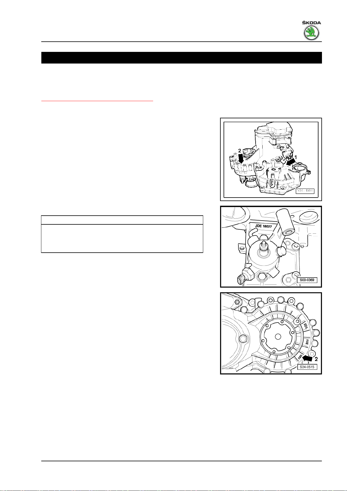
Location on the gearbox
Identification characters and production date -arrow 1-.
Identification of gearbox 02R -arrow 2-.
Gearbox 02R - Edition 08.2014
Identification characters and production date of the gearbox
Example: JDE 18 02 7
Identification of gearbox 02R -arrow 2-.
I I I I
Identifica‐
tion char‐
acters
Day Month Manufacturing
year (2007)
1. Identification of the gearbox 1
Fabia II 2007 ➤ , Fabia II 2009 ➤ , Fabia II 2011 ➤ , Rapid 2011 ➤ , R ...
Gearbox 02R - Edition 08.2014
2 Technical data
⇒ “2.1 Identification characters, aggregate assignment (Fabia II)”,
page 2
⇒ “2.2 Identification characters, aggregate assignment (Room‐
ster)”, page 3
⇒ “2.3 Identification characters, aggregate assignment (Rapid)”,
page 3
⇒ “2.4 Identification characters, aggregate assignment (Rapid
NH)”, page 3
⇒ “2.5 Filling capacity”, page 4
⇒ “2.6 Calculation of gear ratios”, page 4
2.1 Identification characters, aggregate assignment (Fabia II)
Manual gearbox 5 speed 02R
Manufactured from
through
Identification characters JCZ JDE JDD
Assignment: Engine 1.4 ltr./59 kW TDI
02.07
03.10
02.07
03.10
03.08
03.10
Manual gearbox 5 speed 02R
Manufactured from
through
Identification characters JDA JXY
Assignment: Engine 1.9 ltr./77 kW TDI 1.9 ltr./77 kW TDI
Manual gearbox 5 speed 02R
Manufactured from
through
Identification characters KFK, MZL MAL MNY
Assignment: Engine 1.6 ltr./55 kW TDI CR
1.6 ltr./66 kW TDI CR
1.6 ltr./77 kW TDI CR
Manual gearbox 5 speed 02R
Manufactured from
through
Identification characters MUW MZR
Assignment: Engine 1.2 ltr./55 kW TDI CR
04.07
04.07
03.10 03.10
09.10
10.10
04.07
03.10
10.10
1.2 ltr./55 kW TDI CR
11.10
05.10
10.10
Manual gearbox 5 speed 02R
Manufactured from
through
Identification characters MZK MZN MZM
Assignment: Engine 1.2 ltr./55 kW TDI CR 1.6 ltr./66 kW TDI CR
11.10 11.10 11.11
2 Rep. gr.00 - Technical data
Fabia II 2007 ➤ , Fabia II 2009 ➤ , Fabia II 2011 ➤ , Rapid 2011 ➤ , R ...
Gearbox 02R - Edition 08.2014
2.2 Identification characters, aggregate assignment (Roomster)
Manual gearbox 5 speed 02R
Identification characters HZP JEP
Manufac‐
tured
Assignment Engine 1.9 ltr./77 kW TDI
Manual gearbox 5 speed 02R
Identification characters JXZ JDE
Manufac‐
tured
Assignment Engine 1.9 ltr./77 kW TDI 1.4 ltr./59 kW TDI
Manual gearbox 5 speed 02R
Identification characters MQC MQD
Manufac‐
tured
Assignment Engine 1.2 ltr./55 kW TDI CR
from
through
from
through
from
through
03.06
05.06
01.07
03.10
03.10
10.10
05.06
12.06
05.06
03.10
05.10
10.10
Manual gearbox 5 speed 02R
Identification characters MZP MZQ
Manufac‐
tured
Assignment Engine 1.2 ltr./55 kW TDI CR
Manual gearbox 5 speed 02R
Identification characters KFK, MZL
Manufac‐
tured
Assignment Engine 1.6 ltr./55 kW TDI CR
from
through
from
through
11.10 11.10
03.10
1.6 ltr./66 kW TDI CR
1.6 ltr./77 kW TDI CR
2.3 Identification characters, aggregate assignment (Rapid)
Manual gearbox 5 speed 02R
Identification characters MZS MZS QXQ
Manufactured from
through
Assignment: Engine 1.6 ltr./77 kW TDI CR
09.11 08.14
08.15
08.15
2.4 Identification characters, aggregate assignment (Rapid NH)
Manual gearbox 5 speed 02R
2. Technical data 3
Fabia II 2007 ➤ , Fabia II 2009 ➤ , Fabia II 2011 ➤ , Rapid 2011 ➤ , R ...
Gearbox 02R - Edition 08.2014
Manual gearbox 5 speed 02R
Identification characters MZL MZM MZS
Manufactured from
through
Assignment: Engine 1.6 ltr./77 kW TDI CR
07.12 07.12 07.12
2.5 Filling capacity
Filling capacity 2.0 litre
Gearbox oil specification ⇒ Electronic Catalogue of Original Parts
Gear oil change interval Filled for life
2.6 Calculation of gear ratios
Example
Drive wheel ZG1 = 46 ZA1 = 24
Output gear ZG2 = 33 ZA2 = 70
i = ZG2 : ZG1
iG = Ratio of a gear = ZG2 : ZG1 = 33 : 46 = 0,717
iA = Ratio of the final drive = ZA2 : ZA1 = 70 : 24 = 2,917
i
= Total ratio = iG x iA = 0.717 x 2.917 = 2.091
total
1) Z1 = No. of teeth on driving gear, Z2 = No. of teeth on driven gear
1)
5th gear Final drive
4 Rep. gr.00 - Technical data
Fabia II 2007 ➤ , Fabia II 2009 ➤ , Fabia II 2011 ➤ , Rapid 2011 ➤ , R ...
Gearbox 02R - Edition 08.2014
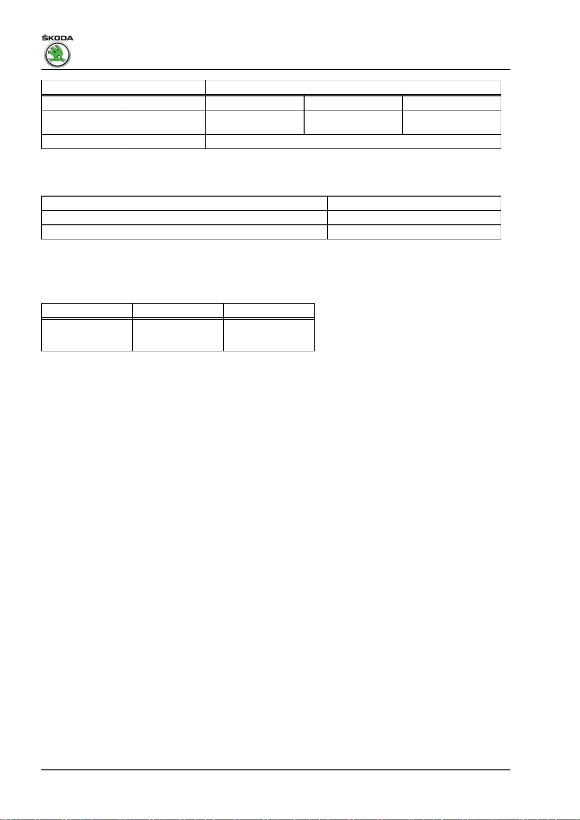
3 Overview of Transmission System
⇒ “3.1 Designation of components and transmission ratio”,
page 5
3.1 Designation of components and transmission ratio
Note
The -arrows- point in the direction of travel.
1 - Engine
2 - Clutch
3 - Manual gearbox
4 - Drive shaft
5 - Output shaft
6 - Differential gear
I - 1. gear
II - 2. gear
III - 3. gear
IV - 4. gear
V - 5. gear
R - Reverse gear
A - Final drive
T - Speedometer drive
❑ for vehicles without ABS
3. Overview of Transmission System 5

Fabia II 2007 ➤ , Fabia II 2009 ➤ , Fabia II 2011 ➤ , Rapid 2011 ➤ , R ...
Gearbox 02R - Edition 08.2014
4 General repair instructions
To ensure flawless and successful gearbox repairs, the greatest
care and cleanliness as well as the use of good and proper tools
are essential. Also note the basic rules on safety when performing
repair procedures.
A number of generally valid notes for individual repair operations
- which are otherwise listed several times at numerous points in
the workshop manual - are summarised here. They apply for this
particular workshop manual.
Gearbox
♦ Thoroughly clean the connection points and their surroundings
before releasing.
♦ Bolts and other attachments should have a classification in the
⇒ Electronic Catalogue of Original Parts .
♦ When installing the manual gearbox, ensure the dowel
sleeves are correctly located between the engine and gear‐
box.
♦ When installing mounts as well as waxed components, the
contact surfaces must be cleaned. Contact surfaces must be
free of wax and grease.
♦ When replacing the gearbox, inspect the gearbox oil level and
top up with oil if necessary
⇒ “3 Check gear oil level”, page 127 .
♦ Filling capacity, Fabia II
⇒ “2.1 Identification characters, aggregate assignment (Fabia
II)”, page 2
♦ Filling capacity, Roomster
⇒ “2.2 Identification characters, aggregate assignment
(Roomster)”, page 3
♦ Filling capacity, Rapid
⇒ “2.3 Identification characters, aggregate assignment (Rap‐
id)”, page 3
♦ Filling capacity, Rapid NH
⇒ “2.4 Identification characters, aggregate assignment (Rapid
NH)”, page 3
♦ Oil specification ⇒ Electronic Catalogue of Original Parts .
Sealant
♦ Thoroughly clean the contact surfaces of the housing before
applying the silicone sealant.
♦ Apply sealant AMV 188 200 03 evenly and not too thick.
6 Rep. gr.00 - Technical data
Fabia II 2007 ➤ , Fabia II 2009 ➤ , Fabia II 2011 ➤ , Rapid 2011 ➤ , R ...
O-rings, gasket rings, gaskets
♦ Replace O-rings, gasket rings and gaskets ⇒ Electronic Cata‐
logue of Original Parts .
♦ After removing gaskets, check the contact surface in the hous‐
ing or shaft for burrs or damage which occured during the
assembly.
♦ Shaft seals - before mounting lightly oil at outside diameter
and fill half the space between the sealing lips -arrow- with
sealing grease - G 052 128 A1- .
♦ The open side of the shaft seals is turned towards the fluid to
be sealed.
♦ Press in new shaft seal in such a way that the sealing lip is not
located on the same point as the sealing lip of the old seal (use
tolerance for insertion depth).
♦ Before inserting lightly oil the O-rings, in order to prevent the
rings being squashed during installation.
♦ Inspect the oil level after replacing the gaskets and gasket
rings, top up oil if necessary
⇒ “3 Check gear oil level”, page 127 .
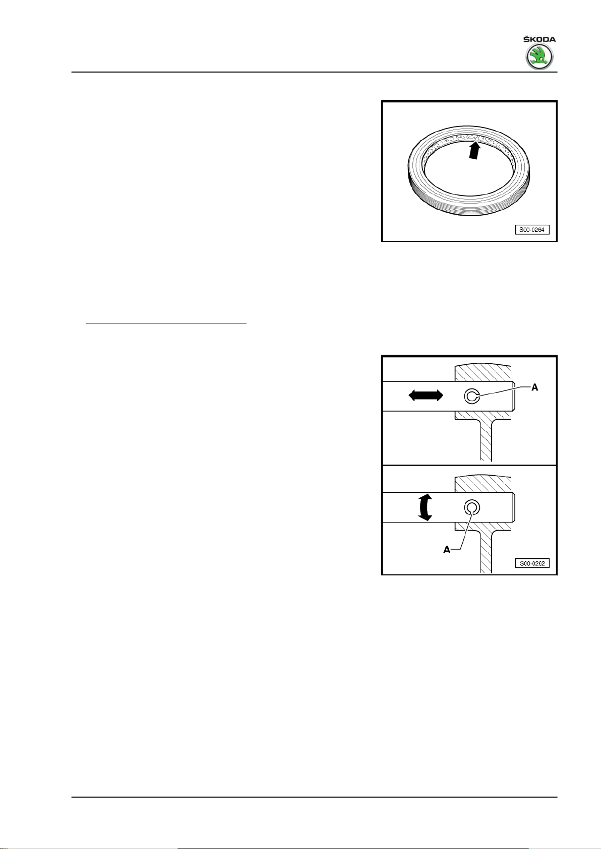
Locking elements
Gearbox 02R - Edition 08.2014
♦ Do not over-tension the circlips.
♦ Always replace damaged or over-tensioned circlips ⇒ Elec‐
tronic Catalogue of Original Parts .
♦ Circlips must be positioned in the base of the groove.
♦ Replace roll pins. Fitting position: Slot -A- longitudinal to power
flow -arrow-.
4. General repair instructions 7
Fabia II 2007 ➤ , Fabia II 2009 ➤ , Fabia II 2011 ➤ , Rapid 2011 ➤ , R ...
Gearbox 02R - Edition 08.2014
Nuts and bolts
♦ Slacken the bolts and nuts against the tightening sequence.
♦ Slacken and tighten nuts and bolts for attaching covers and
housings without tightening sequence diagonally across in
stages.
♦ Replace the self-locking screws and nuts.
♦ Specified torques given are for unlubricated nuts, bolts and
screws.
♦ Clean the threaded holes into which self-locking screws or
screws with locking agent were screwed in (using e.g. a screw-
tap). Otherwise there is a danger of bolts shearing when
subsequently being removed.
♦ It is important to ensure at all bolted connections that the con‐
tact surfaces as well as the nuts and bolts are waxed only after
being installed, should this be necessary.
Bearings
♦ Insert moist all bearings into the gearbox with gear oil.
♦ Before installing, heat the inner rings of the bearing on a heat‐
ing plate or with the induction heater unit - VAS 6414- to
approx. 100°C, when installing press in axial and play-free up
to the stop.
♦ The temperature can be checked with a temperature measur‐
ing instrument.
♦ Do not mix up the outer and inner races of bearings of the
same size.
♦ Always jointly replace tapered-roller bearings on the same
shaft and use products of the same manufacturer.
♦ Position needle bearing with the lettered side (thicker end) to‐
wards the drift pin.
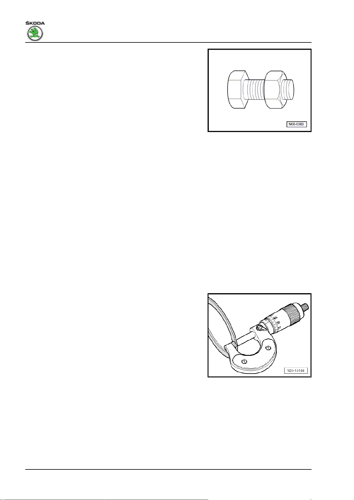
Shims
♦ Measure shims at several points with a micrometer. Different
tolerances allow to measure the required thickness for each
washer very precisely.
♦ Check for burrs and damage.
♦ Install only adjusting washers which are in perfect condition.
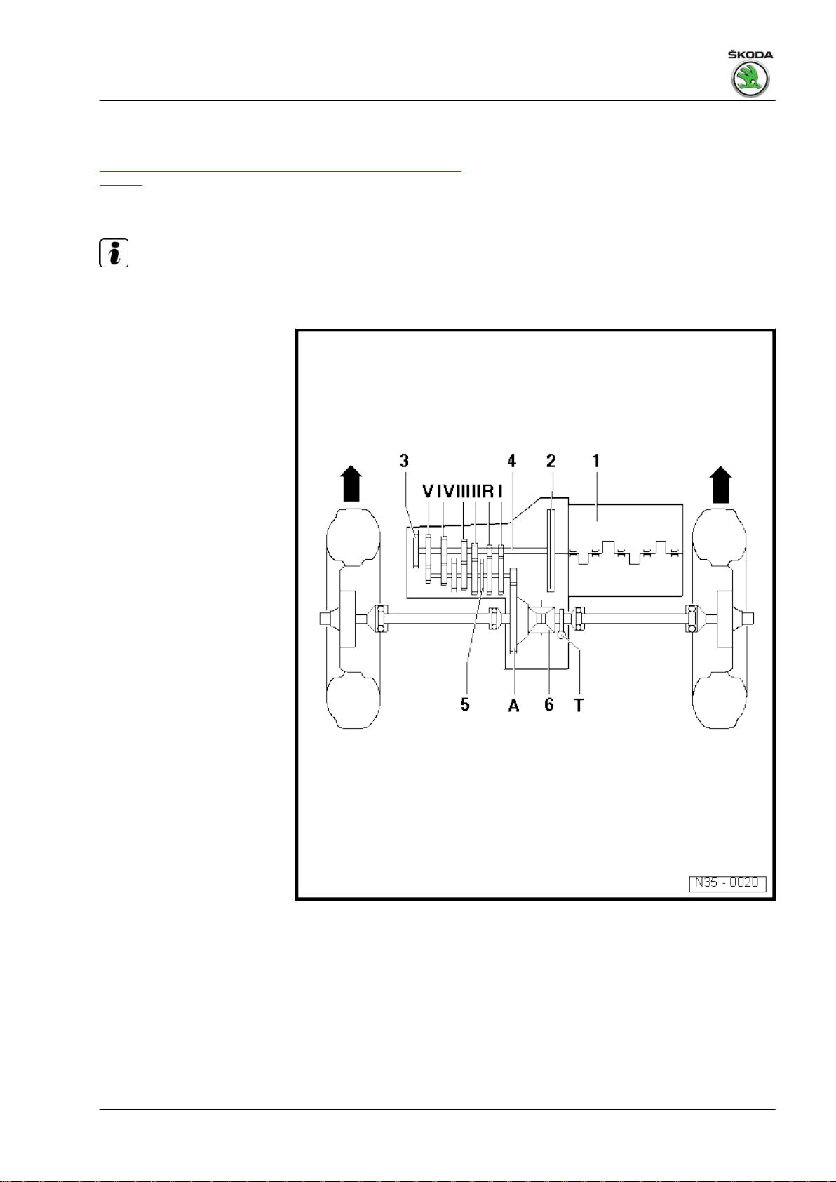
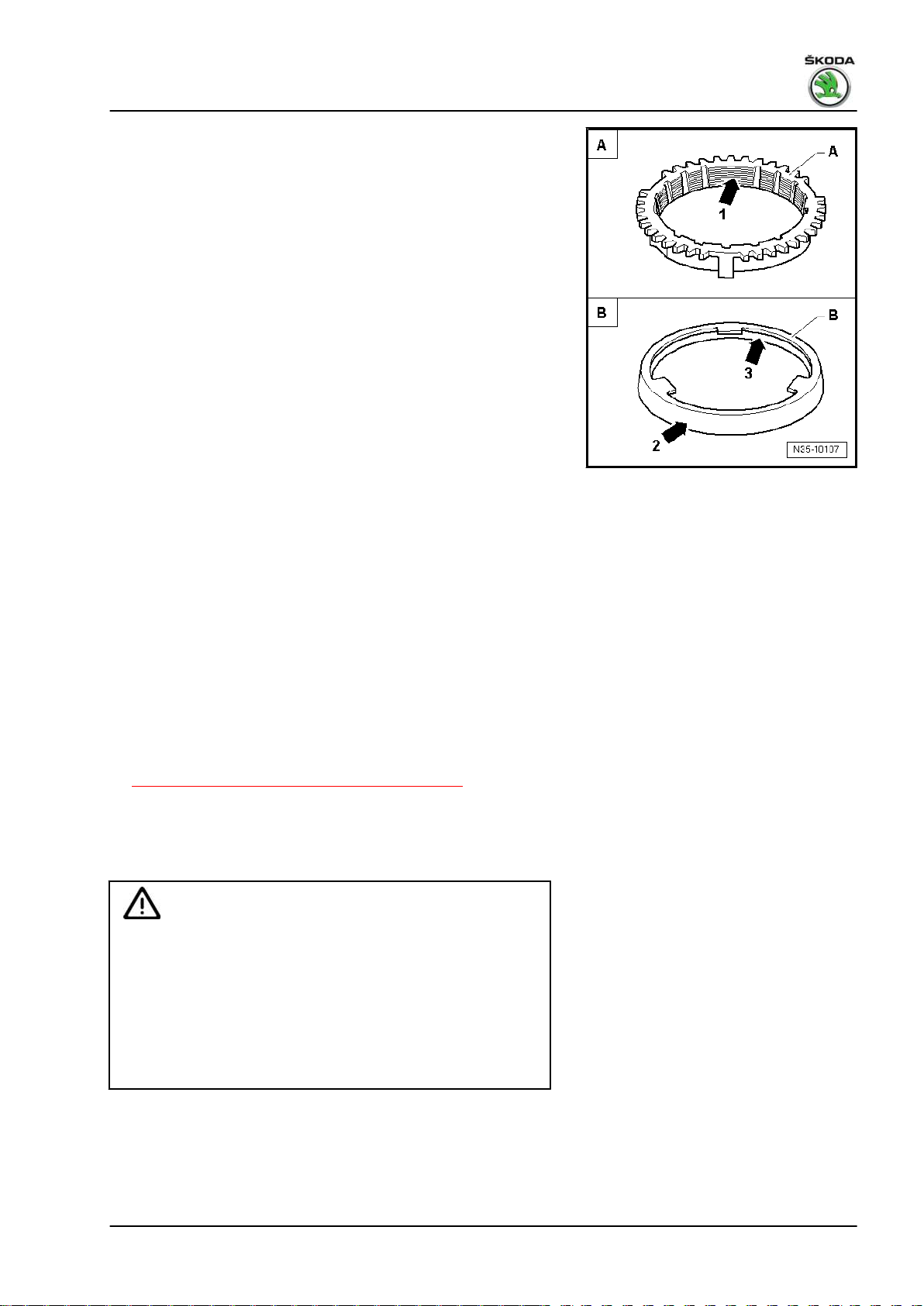
Synchronizer rings
8 Rep. gr.00 - Technical data
Fabia II 2007 ➤ , Fabia II 2009 ➤ , Fabia II 2011 ➤ , Rapid 2011 ➤ , R ...
♦ These are not interchangeable. If re-using, allocate synchron‐
izer rings to the same sliding gear.
♦ Inspect for wear, replace if necessary ⇒ Electronic Catalogue
of Original Parts .
♦ Check grooves -arrow 1- on synchronizer ring -A-, or check
the inside of the ring for flattened parts (grooves worn).
♦ When installing the intermediate ring -B-, check outer contact
surface -arrow 2- and inner contact surface -arrow 3- for
grooves, blue coloring (caused by overheating) and other
damages.
♦ Insert with some gearbox fluid.
Pinions
♦ Clean and heat on a heating plate or with the induction heater
unit - VAS 6414- to approx. 100°C before pressing on.
♦ The temperature can be checked with a temperature measur‐
ing instrument.
♦ Check fitting position.
Sliding gears
♦ Check 1st to 5th gear sliding gears after assembly for low axial
play or smooth operation.
Clutch control
♦ When removing gearbox, remove slave cylinder, do not de‐
tach the tube-hose line.
♦ If the slave cylinder with connected hydraulic line is removed,
do not depress the clutch pedal. Otherwise the tappet is press‐
ed out of the slave cylinder.
♦ Do not tilt the clutch pressure plate; release and tighten cross‐
wise in small stages.
♦ If the clutch pedal does not return to its initial position after the
coupling procedure - clutch pedal in home position - the clutch
control must be bled (further measures
⇒ “1.16 Check hydraulic clutch control”, page 47 ).
♦ In order to reduce unpleasant odours if the clutch is burnt,
thoroughly clean the clutch housing as well as the flywheel and
the engine on the side of the gearbox.
Safety precautions for vehicles with start-stop system
Gearbox 02R - Edition 08.2014
WARNING
On vehicles with start-stop system, there is the risk of injury
from automatic engine start.
♦ On vehicles with activated start-stop system (recogniza‐
ble by a message in the dash panel insert), the engine can
start automatically if required.
♦ It is therefore necessary to ensure that the start-stop sys‐
tem is deactivated when carrying out work on the vehicle
(ignition switched off; if required switch ignition on again).
4. General repair instructions 9

Fabia II 2007 ➤ , Fabia II 2009 ➤ , Fabia II 2011 ➤ , Rapid 2011 ➤ , R ...
Gearbox 02R - Edition 08.2014
30 – Clutch
1 Clutch control
⇒ “1.1 Summary of components - foot controls (Fabia II 2007 ►;
Roomster 2006 ►)”, page 10
⇒ “1.2 Removing and installing the crash strut for the clutch pedal
(Fabia II 2007 ►; Roomster 2006 ►)”, page 14
⇒ “1.3 Removing and installing the over-centre helper spring (Fa‐
bia II 2007 ►; Roomster 2006 ►)”, page 14
⇒ “1.4 Removing and installing the clutch pedal (Fabia II 2007 ►;
Roomster 2006 ►)”, page 16
⇒ “1.5 Summary of components - foot controls (Fabia II 2011 ►;
Roomster 2011 ►; Rapid NH)”, page 17
⇒ “1.6 Summary of components - Foot controls (Rapid) ”,
page 25
⇒ “1.7 Removing and installing the bracket with the master cylin‐
der (Fabia II 2011 ►; Roomster 2011 ►; Rapid NH)”, page 27
⇒ “1.8 Removing and installing the bracket with the master cylin‐
der (Rapid) ”, page 30
⇒ “1.9 Removing and installing the bracket without the master
cylinder (Fabia II 2011 ►; Roomster 2011 ►; Rapid NH)”,
page 32
⇒ “1.10 Removing and installing the bracket without the master
cylinder (Rapid) ”, page 34
⇒ “1.11 Removing and installing the clutch pedal with the overcentre helper spring (Fabia II 2011 ►; Roomster 2011 ►; Rapid
NH)”, page 36
⇒ “1.12 Removing and installing the clutch pedal with the overcentre helper spring (Rapid) ”, page 38
⇒ “1.13 Removing and installing the clutch pedal with the tension
spring (Fabia II 2011 ►; Roomster 2011 ►)”, page 39
⇒ “1.14 Summary of components - Hydraulic (Fabia II ►; Room‐
ster ►; Rapid NH) ”, page 41
⇒ “1.15 Summary of components - Hydraulic (Rapid) ”,
page 44
⇒ “1.16 Check hydraulic clutch control”, page 47
⇒ “1.17 Removing and installing the master cylinder (Fabia II 2007
►; Roomster 2006 ►)”, page 48
⇒ “1.18 Removing and installing the master cylinder (Fabia II 2011
►; Roomster 2011 ►; Rapid 2011 ►; Rapid NH)”, page 50
⇒ “1.19 Removing and installing the slave cylinder”, page 51
⇒ “1.20 Bleeding the clutch control ”, page 54
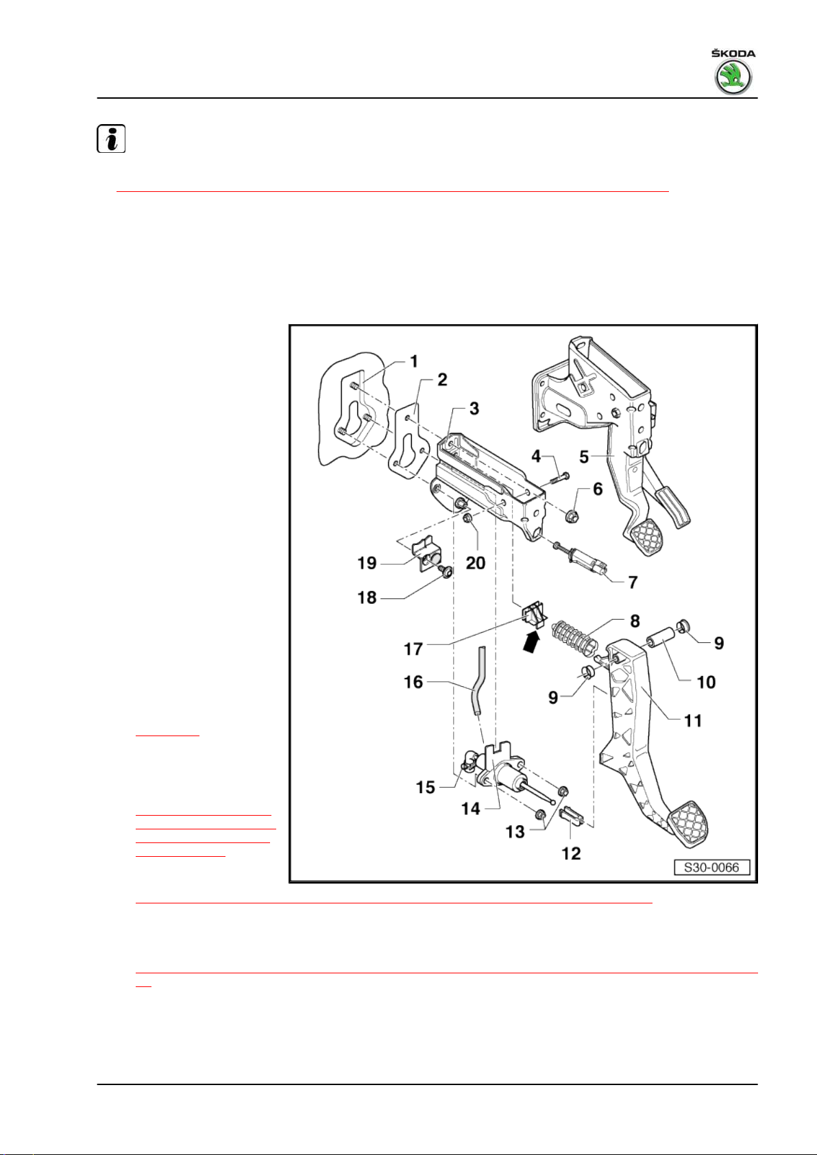
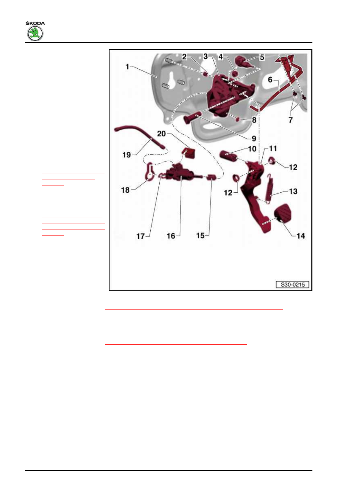
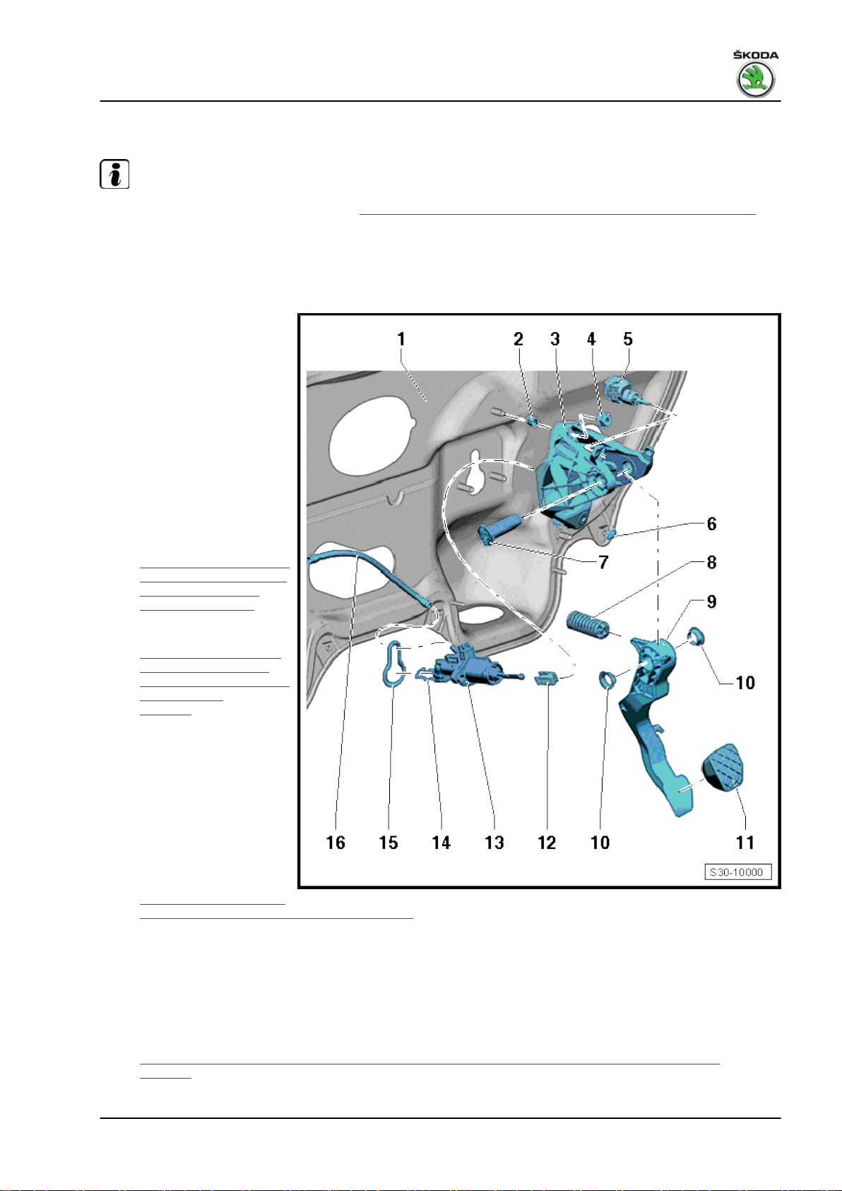
1.1 Summary of components - foot controls (Fabia II 2007 ►; Roomster 2006 ►)
Special tools and workshop equipment required
♦ Polycarbamide grease - G 052 142 A2-
10 Rep. gr.30 - Clutch
Fabia II 2007 ➤ , Fabia II 2009 ➤ , Fabia II 2011 ➤ , Rapid 2011 ➤ , R ...
Gearbox 02R - Edition 08.2014
Note
♦
Summary of components - Hydraulics
⇒ “1.14 Summary of components - Hydraulic (Fabia II ►; Roomster ►; Rapid NH) ”, page 41 .
♦
After the battery earth strap is disconnected and re-connected, carry out additional operations ⇒ Electrical
System; Rep. gr. 27 .
♦
Grease all bearing points and contact surfaces with Polycarbamide Grease - G 052 142 A2- .
♦
Prior to working on the foot controls remove the storage area on the driver's side ⇒ Body Work; Rep. gr.
70 .
1 - Front wall
❑ with mount for bearing
bracket and master cyl‐
inder
2 - Gasket
❑ always replace ⇒ Elec‐
tronic Catalogue of
Original Parts
3 - Bearing bracket
❑ for attaching clutch ped‐
al
4 - Screw
5 - Gas/brake foot controls
6 - 25 Nm
❑ self-locking
❑ for bracket on front wall
❑ always replace ⇒ Elec‐
tronic Catalogue of
Original Parts
7 - Clutch pedal switch - F36-
❑ Difference between
clutch pedal switch
⇒ page 13
❑ Assignment ⇒ Electron‐
ic Catalogue of Original
Parts
❑ Removing and installing
⇒ “1.1.1 removing and
installing, setting angu‐
lar clutch pedal switch
F36 ”, page 13 angular
clutch pedal switch
❑ Removing and installing
⇒ “1.1.2 removing and installing, setting cylindrical clutch pedal switch F36 ”, page 13 cylindrical clutch
pedal switch
8 - Over-centre helper spring
❑ removing and installing
⇒ “1.3 Removing and installing the over-centre helper spring (Fabia II 2007 ►; Roomster 2006 ►)”, page
14
1. Clutch control 11
Fabia II 2007 ➤ , Fabia II 2009 ➤ , Fabia II 2011 ➤ , Rapid 2011 ➤ , R ...
Gearbox 02R - Edition 08.2014
9 - Bushing
10 - Bearing bolt
11 - Clutch pedal
❑ removing and installing
⇒ “1.4 Removing and installing the clutch pedal (Fabia II 2007 ►; Roomster 2006 ►)”, page 16
12 - Support
❑ only replace if the master cylinder has been removed
❑ removing and installing
⇒ “1.14 Summary of components - Hydraulic (Fabia II ►; Roomster ►; Rapid NH) ”, page 41
13 - 25 Nm
❑ self-locking
❑ for master cylinder to front wall
❑ always replace ⇒ Electronic Catalogue of Original Parts
14 - Master cylinder
❑ removing and installing
⇒ “1.17 Removing and installing the master cylinder (Fabia II 2007 ►; Roomster 2006 ►)”, page 48
15 - Clamp
❑ to remove and install the tube-hose line pull out retaining clip up to the stop
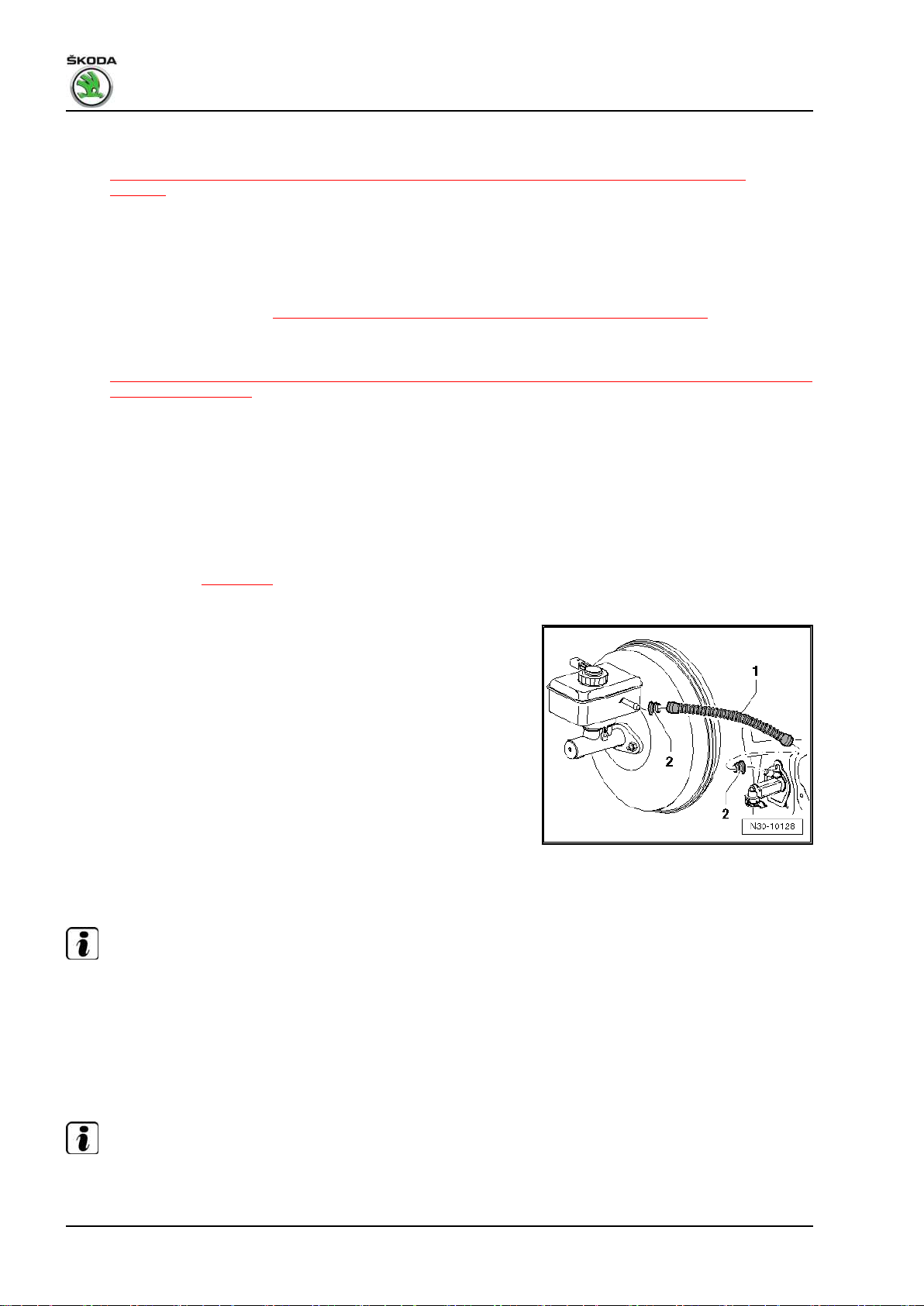
16 - Supply hose
❑ out of plastic ⇒ page 12
17 - Bearing
❑ for over-centre helper spring
❑ insert in bearing bracket
❑ always replace ⇒ Electronic Catalogue of Original Parts
❑ Fitting position: Peg -arrow- clips into the recess on the master cylinder
18 - Screw
❑ for pedal stop on bracket
19 - Pedal stop
❑ screw onto bracket with screw Pos.18 with the master cylinder installed
20 - 25 Nm
❑ self-locking
❑ always replace ⇒ Electronic Catalogue of Original Parts
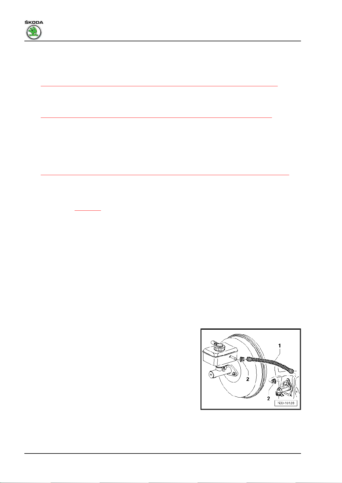
Plastic return hose -1-
• The gaskets -2- must be located in the return hose.
12 Rep. gr.30 - Clutch
Fabia II 2007 ➤ , Fabia II 2009 ➤ , Fabia II 2011 ➤ , Rapid 2011 ➤ , R ...
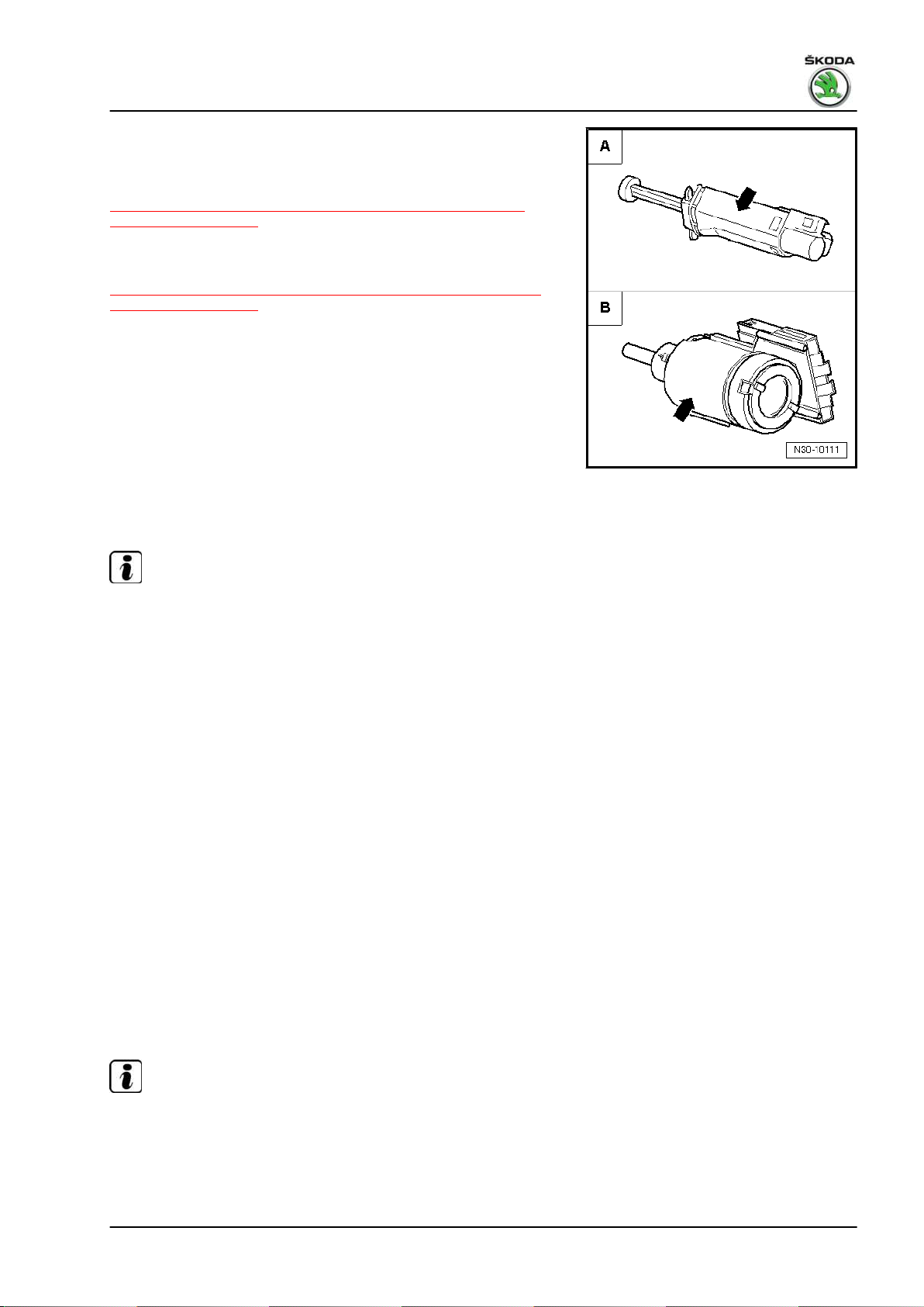
Difference between clutch pedal switches - F36♦ -A- Clutch pedal switch with angular housing
Removing and installing
⇒ “1.1.1 removing and installing, setting angular clutch pedal
switch F36 ”, page 13 .
♦ -B- Clutch pedal switch with cylindrical housing
Removing and installing
⇒ “1.1.2 removing and installing, setting cylindrical clutch pedal
switch F36 ”, page 13 .
1.1.1 removing and installing, setting angular clutch pedal switch - F36-
Gearbox 02R - Edition 08.2014
Note
The clutch pedal switch - F36- may only be installed once to en‐
sure that it has an adequately tight fit in the bracket for clutch
pedal.
Removing
– Remove the storage area on the driver's side ⇒ Body Work;
Rep. gr. 70 .
– Unplug connector from the clutch pedal switch - F36- .
– Turn clutch pedal switch - F36- 90° to the left and remove it
from the support.
Installing and setting
– Pull out the tappet of the clutch pedal switch up to the stop.
– Press down the clutch pedal as far as possible.
– Insert clutch pedal switch into the support and turn switch by
90° to the right.
– Insert connector for the clutch pedal switch - F36- .
– Install the storage area on the driver's side ⇒ Body Work; Rep.
gr. 70 .
1.1.2 removing and installing, setting cylindri‐
cal clutch pedal switch - F36-
Note
The clutch pedal switch - F36- may only be installed once to en‐
sure that it has an adequately tight fit in the bracket for clutch
pedal.
– Remove the storage area on the driver's side ⇒ Body Work;
Rep. gr. 70 .
1. Clutch control 13
Fabia II 2007 ➤ , Fabia II 2009 ➤ , Fabia II 2011 ➤ , Rapid 2011 ➤ , R ...
Gearbox 02R - Edition 08.2014
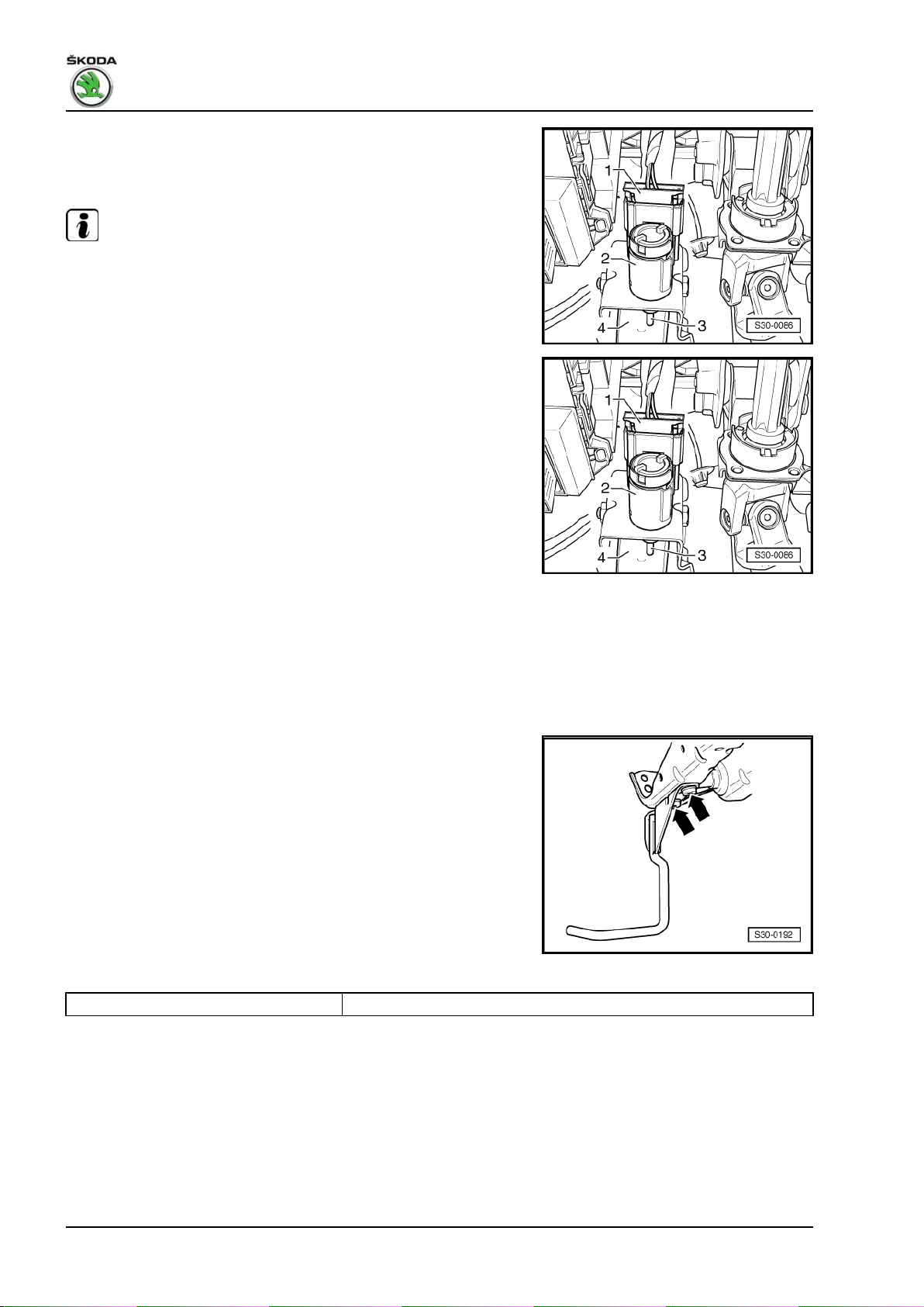
– Unplug connector -1- from the clutch pedal switch - F36- .
– Turn clutch pedal switch - F36- -2- in the bracket 45° to the left
and remove it from the support.
Note
Clutch pedal always remains in the off position in this case (do
not depress the clutch pedal).
Installing and setting
– Before installing the clutch pedal switch - F36- pull out tappet
-3- fully.
• Clutch pedal -4- in the off position.
– Fit the clutch pedal switch - F36- through the assembly open‐
ing, press against the clutch pedal and attach by turning it 45°
to the right.
– Insert connector for the clutch pedal switch - F36- .
– Install the storage area on the driver's side ⇒ Body Work; Rep.
gr. 70 .
1.2 Removing and installing the crash strut
for the clutch pedal (Fabia II 2007 ►;
Roomster 2006 ►)
Removing
– Remove the storage area on the driver's side ⇒ Body Work;
Rep. gr. 70 .
– Release screws -arrows- and remove crash strut.
Install
Installation is carried out in the reverse order.
Tightening torque
Crash strut to steering column 9 Nm
1.3 Removing and installing the over-centre
helper spring (Fabia II 2007 ►; Roomster
2006 ►)
Special tools and workshop equipment required
♦ Pliers - T10005♦ Polycarbamide grease - G 052 142 A2-
14 Rep. gr.30 - Clutch
Fabia II 2007 ➤ , Fabia II 2009 ➤ , Fabia II 2011 ➤ , Rapid 2011 ➤ , R ...
Removing
– Remove the storage area on the driver's side ⇒ Body Work;
Rep. gr. 70 .
– Remove crash strut (if present)
⇒ “1.2 Removing and installing the crash strut for the clutch
pedal (Fabia II 2007 ►; Roomster 2006 ►)”, page 14 .
– Remove clutch pedal switch - F36-
⇒ “1.1 Summary of components - foot controls (Fabia II 2007
►; Roomster 2006 ►)”, page 10 -Pos. 7-, if provided.
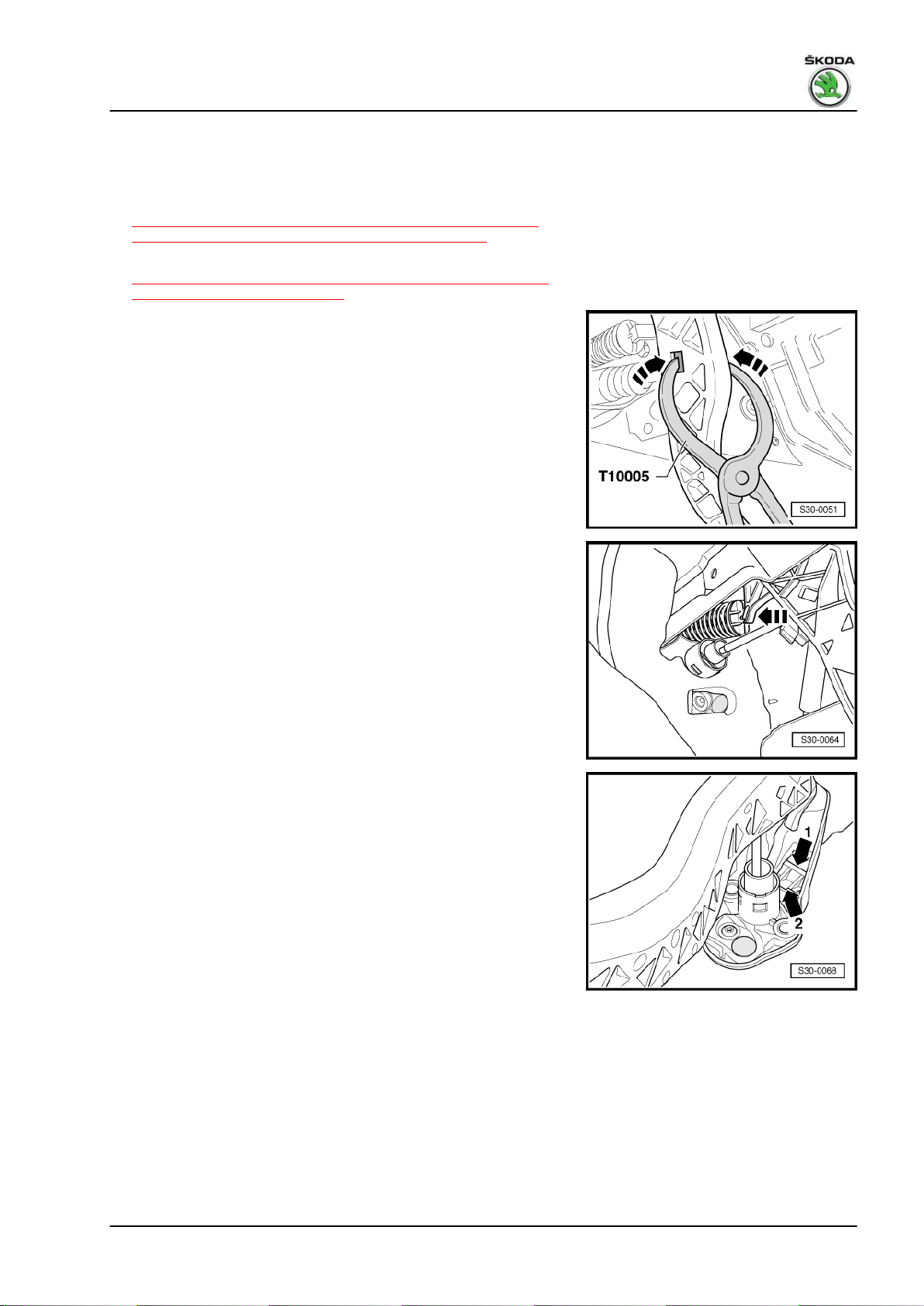
Unlock the actuating rod/master cylinder from the clutch pedal as
follows:
– Pull clutch pedal slightly into the passenger compartment.
– Insert pliers - T10005- in the clutch pedal recesses.
– Press together both sides of the support inwards using the pli‐
ers - T10005- -arrows- and separate the clutch pedal from the
master cylinder.
Gearbox 02R - Edition 08.2014
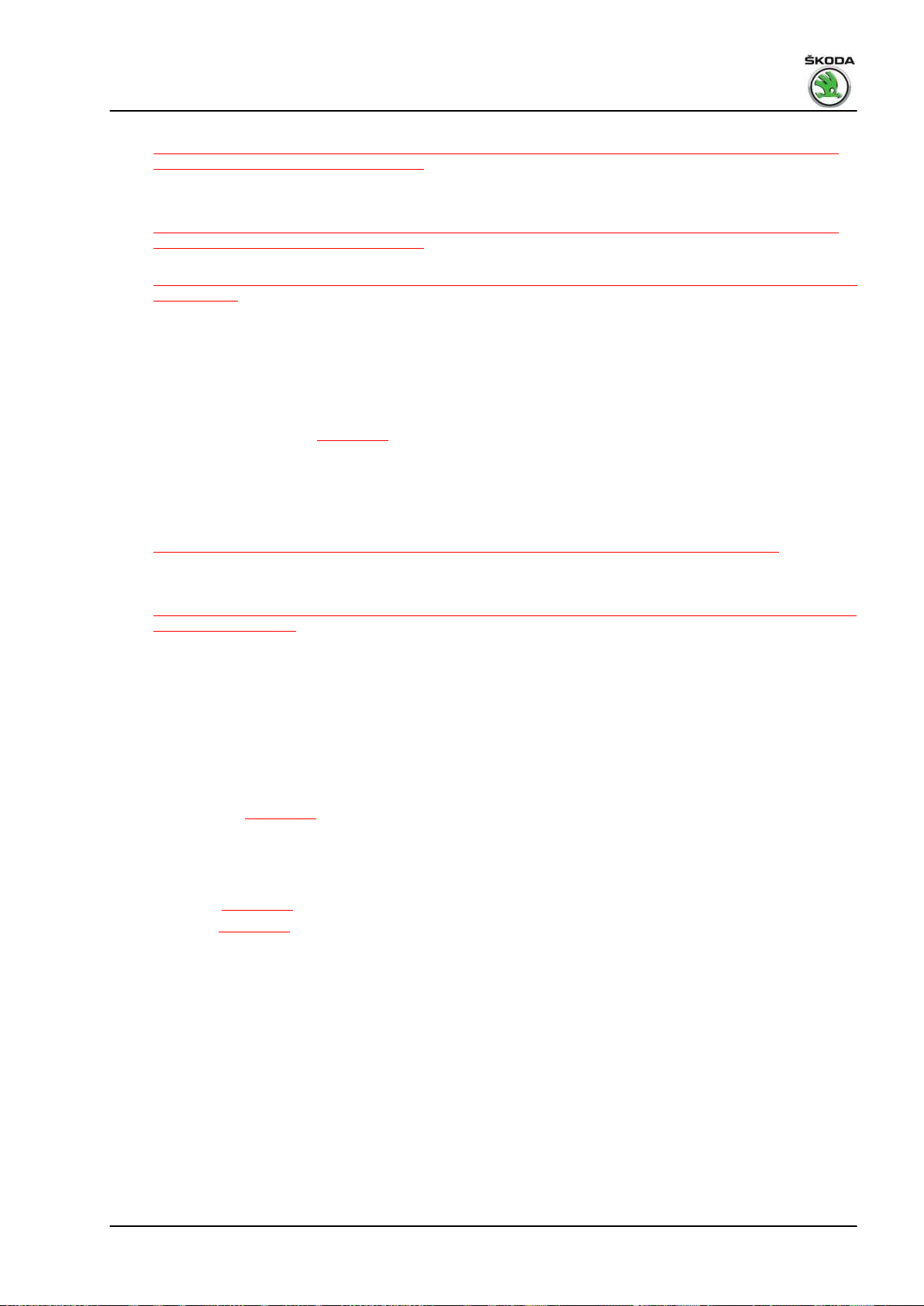
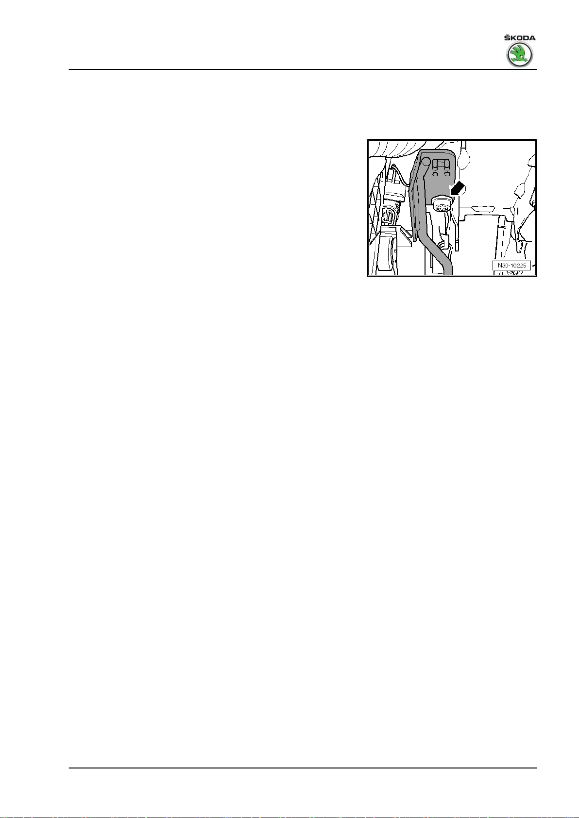
– Press the over-centre helper spring towards the front wall
-in direction of arrow- and remove it downwards.
Install
• Check whether the bearing -arrow 1- for the over-centre helper
spring is inserted in the bracket.
Fitting position:
The peg of the bearing is located in the recess of the master cyl‐
inder -arrow 2-.
– First of all, insert the over-centre helper spring in the rear
bearing.
1. Clutch control 15
Fabia II 2007 ➤ , Fabia II 2009 ➤ , Fabia II 2011 ➤ , Rapid 2011 ➤ , R ...
Gearbox 02R - Edition 08.2014
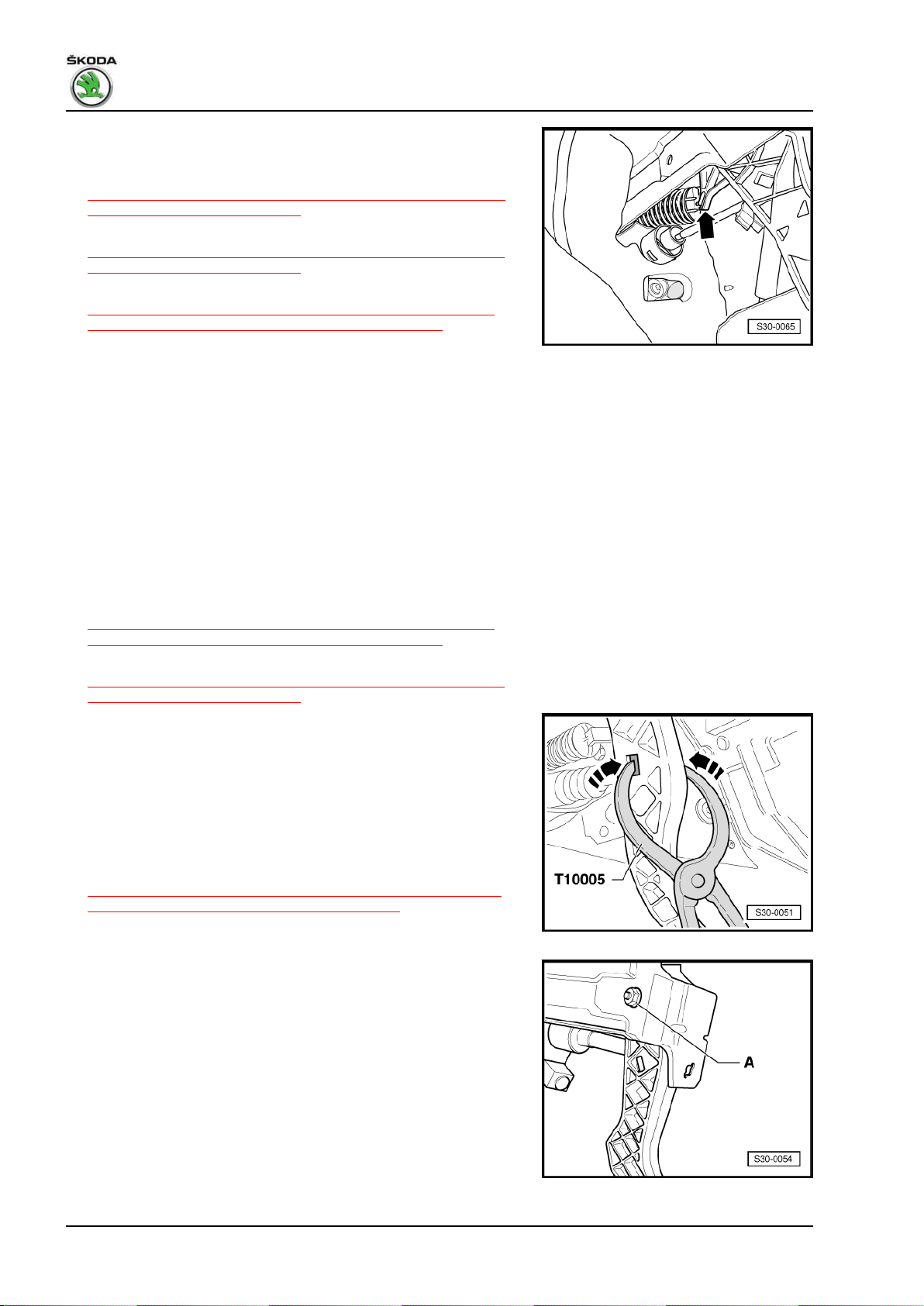
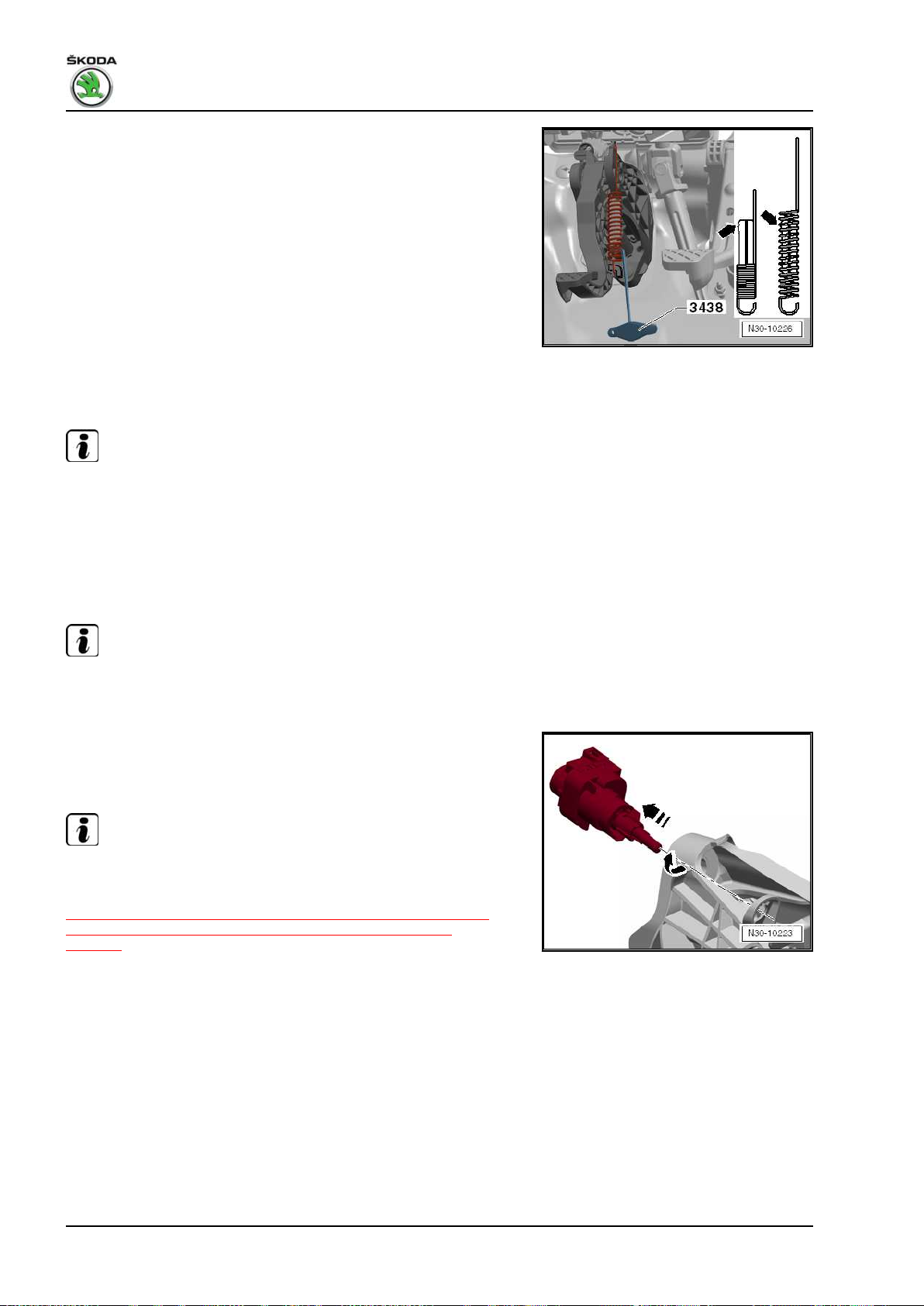
– Then press the over-centre helper spring onto the centering
pin of the clutch pedal -arrow-.
– Position the clutch pedal with the master cylinder
⇒ “1.4 Removing and installing the clutch pedal (Fabia II 2007
►; Roomster 2006 ►)”, page 16 .
– Install clutch pedal switch - F36-
⇒ “1.1 Summary of components - foot controls (Fabia II 2007
►; Roomster 2006 ►)”, page 10 -Pos. 7-.
– Install crash strut (if present)
⇒ “1.2 Removing and installing the crash strut for the clutch
pedal (Fabia II 2007 ►; Roomster 2006 ►)”, page 14 .
– Install the storage area on the driver's side ⇒ Body Work; Rep.
gr. 70 .
1.4 Removing and installing the clutch pedal (Fabia II 2007 ►; Roomster 2006 ►)
Special tools and workshop equipment required
♦ Pliers - T10005♦ Polycarbamide grease - G 052 142 A2Removing
– Remove the storage area on the driver's side ⇒ Body Work;
Rep. gr. 70 .
– Remove crash strut (if present)
⇒ “1.2 Removing and installing the crash strut for the clutch
pedal (Fabia II 2007 ►; Roomster 2006 ►)”, page 14 .
– Remove clutch pedal switch - F36-
⇒ “1.1 Summary of components - foot controls (Fabia II 2007
►; Roomster 2006 ►)”, page 10 -Pos. 7-, if provided.
Unlock the actuating rod/master cylinder from the clutch pedal as
follows:
– Pull clutch pedal slightly into the passenger compartment.
– Insert pliers - T10005- in the clutch pedal recesses.
– Press together both sides of the support inwards using the pli‐
ers - T10005- -arrows- and separate the clutch pedal from the
master cylinder.
– Removing the over-centre helper spring
⇒ “1.3 Removing and installing the over-centre helper spring
(Fabia II 2007 ►; Roomster 2006 ►)”, page 14 .
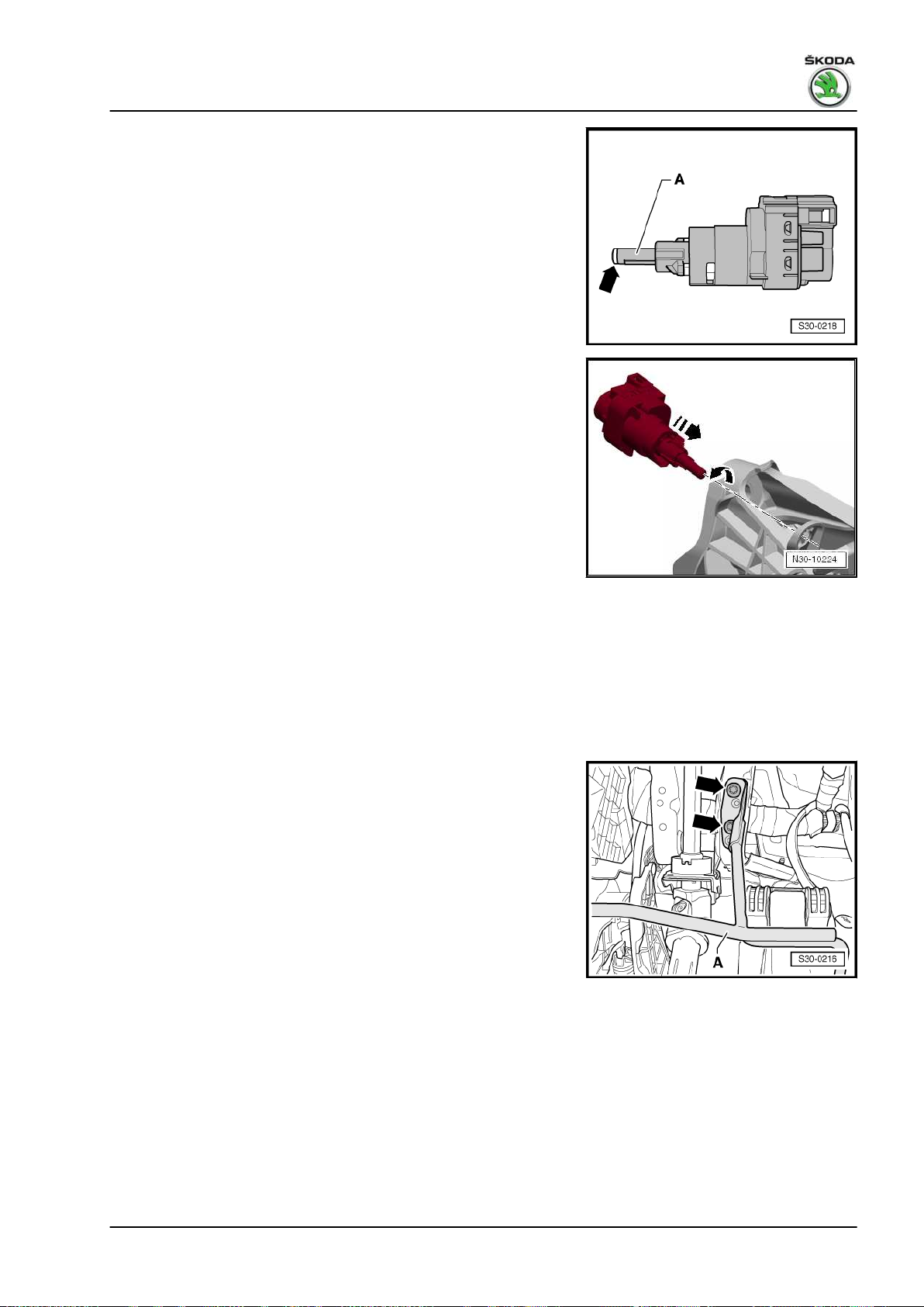
– Put steering wheel in the lower position.
– Unscrew nut -A- and pull out screw from bracket (to facilitate
pulling out the screw, turn the steering wheel to the corre‐
sponding position).
– Remove clutch pedal.
Install
Installation is performed in the reverse order, pay attention to the
following points:
• Always replace self-locking nut ⇒ Electronic Catalogue of
Original Parts .
16 Rep. gr.30 - Clutch
Fabia II 2007 ➤ , Fabia II 2009 ➤ , Fabia II 2011 ➤ , Rapid 2011 ➤ , R ...
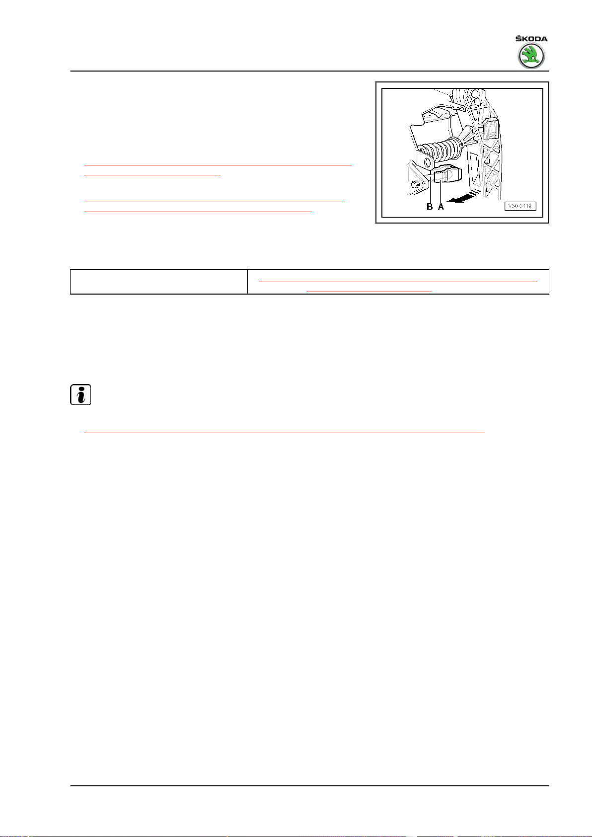
– The support -A- must be located on the actuating rod -B- of
the master cylinder.
– To click in the support, press the clutch pedal towards the front
wall in -direction of arrow-. While doing so, make sure it catch‐
es correctly in the support.
– Install clutch pedal switch - F36-
⇒ “1.1 Summary of components - foot controls (Fabia II 2007
►; Roomster 2006 ►)”, page 10 -Pos. 7-.
– Install crash strut (if present)
⇒ “1.2 Removing and installing the crash strut for the clutch
pedal (Fabia II 2007 ►; Roomster 2006 ►)”, page 14 .
– Install the storage area on the driver's side ⇒ Body Work; Rep.
gr. 70 .
Tightening torque
Gearbox 02R - Edition 08.2014
Clutch pedal to bracket
1)
Replace self-locking nut.
1)
⇒ “1.1 Summary of components - foot controls (Fabia II 2007 ►;
Roomster 2006 ►)”, page 10 -Position 20-
1.5 Summary of components - foot controls (Fabia II 2011 ►; Roomster 2011 ►; Rapid NH)
Note
♦
Summary of components - Hydraulics
⇒ “1.14 Summary of components - Hydraulic (Fabia II ►; Roomster ►; Rapid NH) ”, page 41 .
♦
After the battery earth strap is disconnected and re-connected, carry out additional operations ⇒ Electrical
System; Rep. gr. 27 .
♦
Grease all bearing points and contact surfaces with Polycarbamide Grease - G 052 142 A2- .
1. Clutch control 17
Fabia II 2007 ➤ , Fabia II 2009 ➤ , Fabia II 2011 ➤ , Rapid 2011 ➤ , R ...
Gearbox 02R - Edition 08.2014
1 - Front wall
❑ with mount for bearing
bracket and master cyl‐
inder
2 - Bushing
❑ for the top location hole
in the bracket
❑ The bushings for the
bottom location hole in
the bracket are located
in the master cylinder
3 - Bearing bracket
❑ removing and installing
with master cylinder
⇒ “1.7 Removing and in‐
stalling the bracket with
the master cylinder (Fa‐
bia II 2011 ►; Roomster
2011 ►; Rapid NH)”,
page 27
❑ removing and installing
without master cylinder
⇒ “1.9 Removing and in‐
stalling the bracket with‐
out the master cylinder
(Fabia II 2011 ►; Room‐
ster 2011 ►; Rapid NH)”,
page 32
4 - 25 Nm
❑ for bracket on front wall
❑ self-locking
❑ 3 pieces
❑ always replace ⇒ Elec‐
tronic Catalogue of
Original Parts
5 - Clutch pedal switch - F36-
❑ removing and installing ⇒ “1.5.1 Removing and installing clutch pedal switch F36 ”, page 20
6 - Crash strut
❑ is attached to the steering column
❑ different versions ⇒ electronic catalogue of original parts
❑ removing and installing ⇒ “1.5.2 Removing and installing crash strut”, page 21
7 - Screw
❑ for crash strut Pos. 6 at steering column
❑ Tightening torque:
♦ Version with two screws - 9 Nm
♦ Version with one screw - 20 Nm
8 - Stop
❑ for the clutch pedal
9 - Bracket axle
❑ always replace ⇒ Electronic Catalogue of Original Parts
10 - Over-centre helper spring
❑ depending on the equipment version, a tension spring or an over-centre helper spring is installed
❑ Assign components via the ⇒ Electronic catalogue of original parts
18 Rep. gr.30 - Clutch
Fabia II 2007 ➤ , Fabia II 2009 ➤ , Fabia II 2011 ➤ , Rapid 2011 ➤ , R ...
Gearbox 02R - Edition 08.2014
❑ removing and installing
⇒ “1.11 Removing and installing the clutch pedal with the over-centre helper spring (Fabia II 2011 ►;
Roomster 2011 ►; Rapid NH)”, page 36
11 - Clutch pedal
❑ removing and installing with over-centre helper spring
⇒ “1.11 Removing and installing the clutch pedal with the over-centre helper spring (Fabia II 2011 ►;
Roomster 2011 ►; Rapid NH)”, page 36
❑ with tension springs (Fabia II 2011 ►; Roomster 2011 ►)
⇒ “1.13 Removing and installing the clutch pedal with the tension spring (Fabia II 2011 ►; Roomster 2011
►)”, page 39
12 - Bushing
13 - Tension spring with vibration damper
❑ depending on the equipment version, a tension spring or an over-centre helper spring is installed
❑ Assign components via the ⇒ Electronic catalogue of original parts
❑ is inserted on the bracket Pos. 3 and on the clutch pedal
❑ removing and installing ⇒ page 20
14 - Cap
15 - Support
❑ only replace if the master cylinder has been removed
❑ removing and installing
⇒ “1.14 Summary of components - Hydraulic (Fabia II ►; Roomster ►; Rapid NH) ”, page 41
16 - Master cylinder
❑ removing and installing
⇒ “1.18 Removing and installing the master cylinder (Fabia II 2011 ►; Roomster 2011 ►; Rapid 2011 ►;
Rapid NH)”, page 50
17 - Clamp
❑ to remove and install the tube-hose line pull out retaining clip up to the stop
❑ is pulled out from the side on certain master cylinders
18 - Gasket
❑ always replace ⇒ Electronic Catalogue of Original Parts
❑ stick onto the master cylinder
19 - Supply hose
❑ out of plastic ⇒ page 44
20 - Clutch position sender - G476-
❑ for vehicles with start-stop system
❑ Assign components via the ⇒ Electronic catalogue of original parts
❑ removing ⇒ page 28
❑ installing ⇒ page 30
❑ can be checked in the “targeted fault finding” ⇒ Vehicle diagnostic tester
1. Clutch control 19
Fabia II 2007 ➤ , Fabia II 2009 ➤ , Fabia II 2011 ➤ , Rapid 2011 ➤ , R ...
Gearbox 02R - Edition 08.2014
Removing and installing tension spring
– Insert the vibration damper with the recess -arrows- as of the
2nd spring coil -arrows-.
1.5.1 Removing and installing clutch pedal switch - F36-
Note
The clutch pedal switch - F36- may only be installed once to en‐
sure that it has an adequately tight fit in the bracket for clutch
pedal.
Removing
– Removing the footwell vent ⇒ Heating and Air Conditioning;
Rep. gr. 80 .
Note
The clutch pedal switch is installed from the front wall.
– Unplug connector from the clutch pedal switch - F36- .
– Turn the clutch pedal switch at the bracket 45° in
-direction of arrow- and remove it from the support.
Vehicles Rapid NH
Note
To improve access to the clutch pedal switch - F36- the securing
nuts for the bearing bracket for the clutch pedal can be removed
and the bearing bracket removed in part
⇒ “1.9 Removing and installing the bracket without the master
cylinder (Fabia II 2011 ►; Roomster 2011 ►; Rapid NH)”,
page 32 .
Continued for all vehicles
Install
20 Rep. gr.30 - Clutch
Fabia II 2007 ➤ , Fabia II 2009 ➤ , Fabia II 2011 ➤ , Rapid 2011 ➤ , R ...
• The tappet -A- of the clutch pedal switch must not be pulled
out.
• Grease the tappet head -arrow-.
• Assign the grease via the ⇒ Electronic Catalogue of Original
Parts .
• When installing the clutch pedal switch the clutch pedal must
always remain in the off position. During the complete assem‐
bly, the clutch pedal must only be touched with the tappet head
-arrow- of the clutch pedal switch .
The clutch pedal switch is installed from the front wall.
– Insert the clutch pedal switch into the support of the bracket
and turn it 45° in -direction of arrow-.
– Insert connector for the clutch pedal switch .
– Install the footwell vent ⇒ Heating and Air Conditioning; Rep.
gr. 80 .
Gearbox 02R - Edition 08.2014
1.5.2 Removing and installing crash strut
There are two different versions of crash strut for clutch pedal
which can be fitted to the steering column.
Version with two fixing screws
Removing
– Remove the storage area on the driver's side ⇒ Body Work;
Rep. gr. 70 .
– Release screws -arrows-.
Install
Installation is carried out in the reverse order.
1. Clutch control 21
Fabia II 2007 ➤ , Fabia II 2009 ➤ , Fabia II 2011 ➤ , Rapid 2011 ➤ , R ...
Gearbox 02R - Edition 08.2014
Tightening torque
Crash strut to steering column (2 screws) 9 Nm
22
Fabia II 2007 ➤ , Fabia II 2009 ➤ , Fabia II 2011 ➤ , Rapid 2011 ➤ , R ...
Version with one fixing screw
Removing
– Remove the storage area on the driver's side ⇒ Body Work;
Rep. gr. 70 .
– Unscrew plug -arrow-.
– Unhook the crash strut from the steering column.
Install
Installation is carried out in the reverse order.
Gearbox 02R - Edition 08.2014
23
Fabia II 2007 ➤ , Fabia II 2009 ➤ , Fabia II 2011 ➤ , Rapid 2011 ➤ , R ...
Gearbox 02R - Edition 08.2014
Tightening torque
Crash strut to steering column (1 screw) 20 Nm
24
Fabia II 2007 ➤ , Fabia II 2009 ➤ , Fabia II 2011 ➤ , Rapid 2011 ➤ , R ...
Gearbox 02R - Edition 08.2014
1.6 Summary of components - Foot controls (Rapid)
Note
♦
Summary of components - Hydraulics ⇒ “1.15 Summary of components - Hydraulic (Rapid) ”, page 44 .
♦
After the battery earth strap is disconnected and connected, carry out additional operations ⇒ Electrical
System; Rep. gr. 27 .
♦
Grease all bearing points and contact surfaces with Polycarbamide Grease - G 052 142 A2- .
1 - Front wall
❑ with mount for bearing
bracket and master cyl‐
inder
2 - Bushing
❑ for the top location hole
in the bracket
❑ The bushings for the
bottom location hole in
the bracket are located
in the master cylinder
3 - Bearing bracket
❑ removing and installing
with master cylinder
⇒ “1.8 Removing and in‐
stalling the bracket with
the master cylinder
(Rapid) ”, page 30
❑ removing and installing
without master cylinder
⇒ “1.10 Removing and
installing the bracket
without the master cylin‐
der (Rapid) ”,
page 34
4 - 25 Nm
❑ for bracket on front wall
❑ self-locking
❑ 3 pieces
❑ always replace ⇒ Elec‐
tronic Catalogue of
Original Parts
5 - Clutch pedal switch - F36-
❑ removing and installing
⇒ “1.6.1 Removing and
installing clutch pedal switch F36 ”, page 26
6 - Stop
❑ for the clutch pedal
7 - Bracket axle
❑ always replace ⇒ Electronic Catalogue of Original Parts
8 - Over-centre helper spring
❑ removing and installing
⇒ “1.12 Removing and installing the clutch pedal with the over-centre helper spring (Rapid) ”,
page 38
25
Fabia II 2007 ➤ , Fabia II 2009 ➤ , Fabia II 2011 ➤ , Rapid 2011 ➤ , R ...
Gearbox 02R - Edition 08.2014
9 - Clutch pedal
❑ removing and installing with over-centre helper spring
⇒ “1.12 Removing and installing the clutch pedal with the over-centre helper spring (Rapid) ”,
page 38
10 - Bushing
11 - Cap
12 - Support
❑ only replace if the master cylinder has been removed
❑ removing and installing ⇒ “1.15 Summary of components - Hydraulic (Rapid) ”, page 44
13 - Master cylinder
❑ removing and installing
⇒ “1.18 Removing and installing the master cylinder (Fabia II 2011 ►; Roomster 2011 ►; Rapid 2011 ►;
Rapid NH)”, page 50
14 - Clamp
❑ to remove and install the tube-hose line pull out retaining clip up to the stop
❑ is pulled out from the side on certain master cylinders
15 - Gasket
❑ always replace ⇒ Electronic Catalogue of Original Parts
❑ stick onto the master cylinder
16 - Supply hose
❑ out of plastic ⇒ page 26
Plastic return hose -1-
• The gaskets -2- must be located in the return hose.
1.6.1 Removing and installing clutch pedal
switch - F36-
Note
The clutch pedal switch - F36- may only be installed once to en‐
sure that it has an adequately tight fit in the bracket for clutch
pedal.
Removing
– Removing the footwell vent ⇒ Heating and Air Conditioning;
Rep. gr. 80 .
Note
The clutch pedal switch is installed from the front wall.
26
 Loading...