

Page 1
SIMPLY CLEVER
ŠKODA Rapid
Owner's Manual
Page 2

Layout of this Owner's Manual
(explanations)
This Owner's Manual has been systematically designed to make it easy for you to
search for and obtain the information you require.
Chapters, table of contents and subject index
The text of the Owner's manual is divided into relatively short sections which are
combined into easy-to-read chapters. The chapter you are reading at any particular
moment is always specified on the bottom right of the page.
The Table of contents is arranged according to the chapters and the detailed Sub-
ject index at the end of the Owner's Manual helps you to rapidly find the information you are looking for.
Direction indications
All direction indications such as “left”, “right”, “front”, “rear” relate to the direction of
travel of the vehicle.
Units of measurement
All values are expressed in metric units.
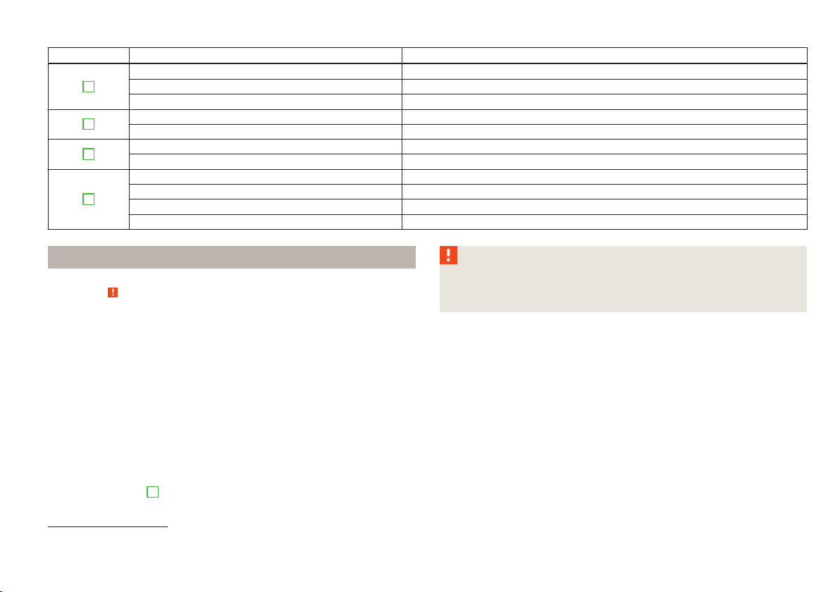
Explanation of symbols
Denotes a reference to a section with important information and safety
advice in a chapter.
Denotes the end of a section.
Denotes the continuation of a section on the next page.
Indicates situations where the vehicle must be stopped as soon as possi-
ble.
® Denotes a registered trademark.
Indicates the texts displayed in the MAXI DOT screen.
Indicates the texts shown in the segment display.
Display
In this owner's manual, the screen on the MAXI DOT display is used as the display
illustration, provided it is not otherwise stated.
Notes
WARNING
The most important notes are marked with the heading WARNING. These
WARNING notes draw your attention to a serious risk of accident or injury.
CAUTION
A Caution note draws your attention to the possibility of damage to your vehicle
(e.g. damage to gearbox), or points out general risks of an accident.
For the sake of the environment
An Environmental note draws your attention to environmental protection aspects.
This is where you will, for example, find tips aimed at reducing your fuel consumption.
Note
A normal Note draws your attention to important information about the operation
of your vehicle.
Page 3

Preface
You have opted for a ŠKODA – our sincere thanks for your confidence in us.
You have received a vehicle with the latest technology and range of amenities. Please read this Owner's
Manual carefully, because the operation in accordance with these instructions is a prerequisite for proper use
of the vehicle.
If you have any questions about your vehicle, please contact a ŠKODA Service Partner.
We wish you much pleasure with your ŠKODA and pleasant motoring at all times.
Your ŠKODA AUTO a.s. (hereinafter referred to only as ŠKODA or manufacturer)
Page 4

On-board literature
The on-board literature for your vehicle consists of this “owner's manual” as well
as a “service schedule” and the “Help on the road” brochure.
Depending on the vehicle model and equipment, other additional operating manuals and instructions may be provided (e.g. an operating manual for the radio).
If one of the documents listed above is missing, please contact a ŠKODA Partner.
Terms used
The on-board literature contains the following terms relating to the service work
for your vehicle.
“Specialist garage” - A Workshop that carries out specialist service tasks for
›
ŠKODA vehicles. A specialist garage can be a ŠKODA partner, a ŠKODA service
partner or an independent workshop.
“ŠKODA service partner” - A Workshop that has been contractually authorized
›
by the manufacturer ŠKODA AUTO a.s. or its sales partner to perform service
tasks on ŠKODA vehicles and to sell ŠKODA Genuine Parts.
“ŠKODA partner” - A company that has been authorized by the manufacturer
›
ŠKODA AUTO a.s. or its sales partner to sell new ŠKODA vehicles and, when applicable, to service them using ŠKODA Genuine Parts and sell ŠKODA Genuine
Parts.
The owner's manual
This Owner's manual describes all possible equipment variants without identifying them as special equipment, model variants or market-dependent equipment.
Consequently, this vehicle does not need to contain all of the equipment compo-
nents described in this owner's manual.
The scope of equipment of your vehicle relates to your purchase contract for the
vehicle. For more information, contact your local ŠKODA retailer.
The illustrations can differ in minor details from your vehicle; they are only intended for general information.
The service schedule:
contains vehicle data including information on service work carried out;
›
is intended as proof of services carried out;
›
is intended for records relating to the mobility warranty (only valid for some
›
countries);
serves as a warranty certificate from the ŠKODA Partner where your vehicle was
›
purchased.
Therefore please always present the service schedule when you take your vehicle
to a specialist garage.
If the service schedule is missing or in poor condition, please contact the specialist garage that regularly services your vehicle. You will need to request a duplicate, in which the specialist garage will confirm the service work previously carried out.
The Help on the road brochure
The Help on the road brochure contains the most important emergency telephone numbers as well as telephone numbers and contact addresses of ŠKODA
Partners in the various different countries.
Page 5
Table of Contents
Abbreviations
Using the system
Cockpit 7
Overview 6
Instruments and Indicator Lights 8
Instrument cluster 8
Warning Lights 12
Information system
Driver information system 20
Multifunction display (MFA)
MAXI DOT display
Service Interval Display 26
Unlocking and opening
Unlocking and locking 28
Anti-theft alarm system
Luggage compartment lid
Electrical power windows 35
Lights and visibility
Lights 38
Interior light
Visibility
Windscreen wipers and washers 44
Rear mirror
Seats and useful equipment 48
Adjusting the seats
Seat features
Practical features 52
Luggage compartment
20
22
25
28
33
34
38
42
43
46
48
50
60
Variable loading floor in the luggage
compartment (Rapid Spaceback) 66
Roof rack system 69
Heating and air conditioning system 71
Heating, ventilation, cooling 71
Heating 72
Air conditioning system (manual air conditioning
system) 74
Climatronic (automatic air conditioning
system) 77
Communication and multimedia 80
Universal telephone installation GSM II 80
Voice control 85
Multimedia
Driving
Starting-off and Driving
Steering 91
Starting and stopping the engine
Brakes 94
Manual gear changing and pedals
Automatic transmission
Running in 99
Economical driving and environmental
sustainability 100
Avoiding damage to your vehicle
Driving abroad
Assist systems 107
Brake assist systems
Parking aid 109
Cruise Control System
START-STOP
Towing a trailer 115
Towing device
Trailer 119
104
105
107
110
112
115
Safety
Passive Safety 122
General information 122
Correct seated position 123
Seat belts 126
Using seat belts 126
Inertia reels and belt tensioners 129
Airbag system 131
Description of the airbag system 131
Airbag overview 132
Deactivating airbags 135
87
Transporting children safely 138
Child seat
Fastening systems 141
91
General Maintenance
92
Taking care of and cleaning the vehicle
Washing your car
96
Taking care of your vehicle exterior 144
97
Taking care of the interior
Modifications, repairs and technical alterations 150
Inspecting and replenishing
Fuel
Engine compartment
Engine oil
Coolant 161
Brake fluid
Vehicle battery
Wheels 168
Tyres and wheel rims
Winter operation 173
138
143
143
148
153
153
155
159
163
164
168
Table of Contents
3
Page 6

Do-it-yourself
Emergency equipment and self-help 175
Emergency equipment 175
Changing a wheel 177
Tyre repair 180
Jump-starting 182
Towing the vehicle 184
Remote control 186
Emergency unlocking/locking 187
Replacing windscreen wiper blades 188
Fuses and light bulbs 190
Fuses 190
Bulbs
193
Technical data
Technical data 200
Vehicle data
200
Index
4
Table of Contents
Page 7

Abbreviations
Abbreviation Definition
rpm Engine revolutions per minute
ABS Anti-lock brake system
AG Automatic gearbox
TCS Traction control
CO2 in g/km discharged quantity of carbon dioxide in grams per driven kilo-
meter
DPF Diesel particle filter
DSG Automatic double clutch gearbox
EDL Electronic differential lock
ECE Economic Commission for Europe
ESC Electronic Stability Control
EU European Union
GSM Groupe Spécial Mobile - a digital network of mobile devices for
the transmission of voice and data
HBA Hydraulic brake assist
HFP Hands-free profile - connection of a mobile device by means of
its Bluetooth® profile
HHC Uphill start assist
kW Kilowatt, measuring unit for the engine output
MDI Mobile Device Interface - connecting an external device via
the AUX or USB input
MFD Multifunction display
MG Manual gearbox
MPI Gasoline engine with a multi-point fuel injection
N1 Panel van intended exclusively or mainly for the transporta-
tion of goods
Nm Newton meter, measuring unit for the engine torque
PIN Personal Identification Number - personal identification num-
ber for the connection of electronic devices using Bluetooth
Abbreviation Definition
TDI CR Diesel engine with turbocharging and common rail injection
TSI Petrol engine with turbocharging and direct injection
®
system
Abbreviations
5
Page 8
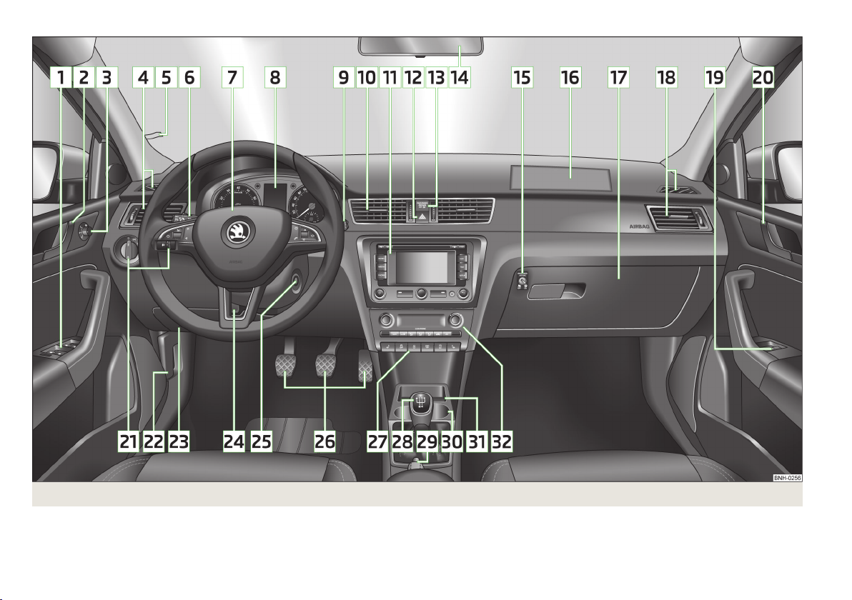
Fig. 1
6
Using the system
Cockpit
Page 9
Using the system
Cockpit
Overview
1
Electrical power windows 36
2
Door opening lever on the driver's side 32
3
Electric exterior mirror adjustment 47
4
Air outlet vents on the driver's side 71
5
Parking ticket holder 52
6
Operating lever:
Turn signal light, headlight and parking light, headlight flasher 40
›
Speed regulating system
›
7
Steering wheel:
With horn
›
With driver’s front airbag
›
with pushbuttons for radio, navigation system and mobile
›
phone 80
8
Instrument cluster 8
9
Operating lever:
Windscreen wiper and wash system
›
Information system 20
›
10
Air outlets in the central part of the dash panel
11
Depending on equipment fitted:
Radio
›
Navigation system
›
12
Button for hazard warning light system
13
Warning light for the deactivated front seat passenger airbag
14
Interior rear-view mirror 46
15
Key switch for switching off the passenger airbag (in front passenger storage compartment) 136
16
Front passenger airbag
17
Storage compartment on the front passenger side
18
Air outlet vents on the front passenger side 71
19
Power window in the front passenger door
20
Door opening lever on the front passenger side 32
21
Light switch and headlight beam range regulation (on the dash
panel) 38, 38
22
Bonnet release lever 157
23
Fuse box in the dashboard 190
24
Lever for adjusting the steering wheel 91
25
Ignition lock 93
26
Pedals 96
27
Bar with keys depending on the equipment fitted:
Seat heater on the front left seat 50
›
TCS
›
Central locking system 31
›
Rear window heater 43
›
START STOP 112
›
Seat heater on the front right seat 50
›
28
110
133
45
71
Depending on equipment fitted:
Gearshift lever (manual gearbox)
›
Selector lever (automatic gearbox) 97
›
29
Handbrake lever
30
Depending on equipment fitted:
Cup holder 54
›
Multimedia holder
›
Ashtrays 55
›
31
Storage compartment
32
Depending on equipment fitted:
Operating controls for the heating 72
›
Operating controls for the air conditioning system
›
Operating controls for Climatronic 77
›
Note
41
The arrangement of the controls and switches and the location of some items on
136
right-hand drive models may differ from that shown in » Fig. 1. The symbols on
the controls and switches are the same as for left-hand drive models.
133
59
35
107
96
95
57
54
74
Cockpit
7
Page 10
Instruments and Indicator Lights
Instrument cluster
Introduction
This chapter contains information on the following subjects:
Overview
Engine revolutions counter 9
Display 9
Speedometer 9
Coolant temperature gauge display 10
Fuel gauge display 10
Counter for distance driven
Digital clock 11
Display of the second speed
Auto Check Control
When the ignition is on, the instrument cluster is illuminated1).
Fault display
If there is a fault in the instrument cluster, the Error message will appear in the
display. Have the fault rectified as soon as possible by a specialist garage.
WARNING
■
Concentrate fully at all times on your driving! As the driver you are fully re-
sponsible for road safety.
■
Never operate the controls in the instrument cluster while driving, only
when the vehicle is stationary!
Overview
8
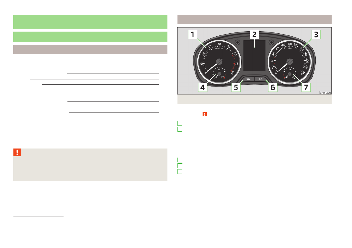
Fig. 2 Instrument cluster
11
11
11
1
Revolutions counter with warning lights » page 9
2
Display» page 9:
With counter for distance driven » page 11
›
With service interval display » page 26
›
With digital clock » page 11
›
with multifunction display (MFA) » page 22
›
With information system » page 20
›
3
Speedometer with warning lights » page 9
4
Coolant temperature gauge1)» page 10
5
Button for display mode:
Setting the hours/minutes » page 11
›
Enable / disable the display of the second speed2) » page 11
›
Service intervals - Display of the number of days and kilometres remaining
›
until the next service2) » page 26
First read and observe the introductory information and safety warnings on page 8.
1)
Applies to vehicles using the MAXI DOT display.
2)
Applies to vehicles with a segment display.
8
Using the system
Page 11
6
Button for:
Reset trip counter for the distance driven » page 11
›
Set hours/minutes
›
enable / disable the mode selected by means of the 5 key
›
7
Fuel gauge1) » page 10
Engine revolutions counter
First read and observe the introductory information and safety warnings on page 8.
The red scale of the rev counter 1 » Fig. 2 on page 8 indicates the range in which
the system begins to limit the engine speed. The system automatically restricts
the engine speed to a steady limit.
You should shift into the next highest gear before the red scale of the revolution
counter is reached, or select mode D on the automatic gearbox.
Follow the recommended gear to prevent engine speeds that are too high or too
low » page 22.
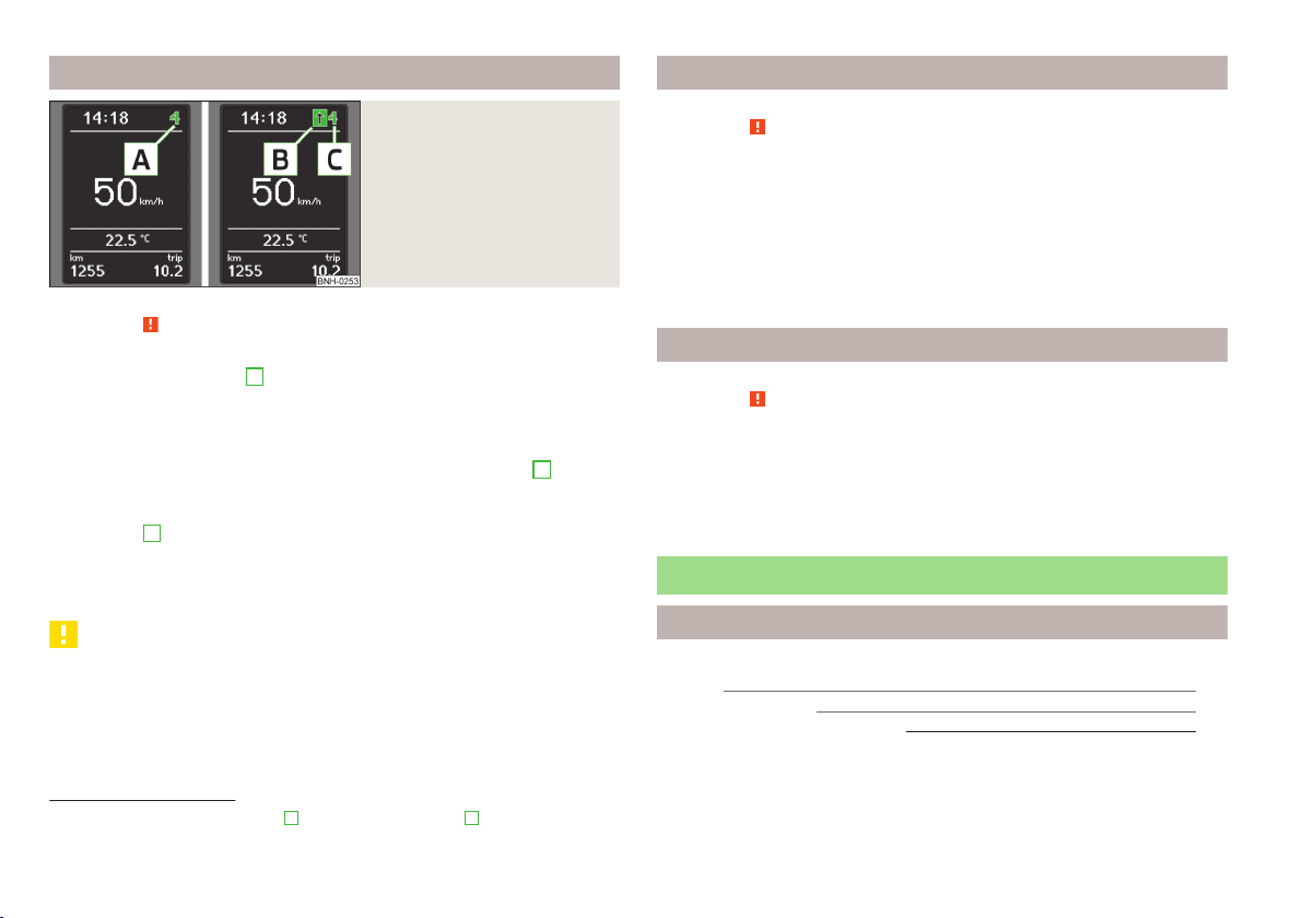
Display
First read and observe the introductory information and safety warnings on page 8.
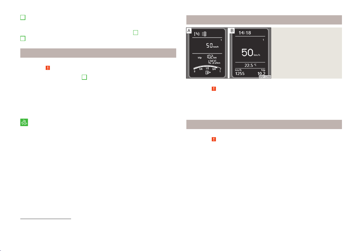
The instrument cluster can have one of the following types of display » Fig. 3.
Segment display, indicated in the text with the symbol
MAXI DOT display, indicated in the text with the symbol
Fig. 3
Display types
For the sake of the environment
Correct shifting up has the following advantages.
■
It helps to reduce fuel consumption.
■
It reduces the operating noise.
■
It protects the environment.
■
It benefits the durability and reliability of the engine.
1)
Applies to vehicles using the MAXI DOT display.
2)
This function only applies to certain countries.
Speedometer
First read and observe the introductory information and safety warnings on page 8.
Warning against excessive speeds
An audible warning signal will sound when the vehicle speed exceeds 120 km/h2).
The audible warning signal is switched off when the vehicle speed falls below 120
km/h.
Instruments and Indicator Lights
9
Page 12
Coolant temperature gauge display
Fuel gauge display
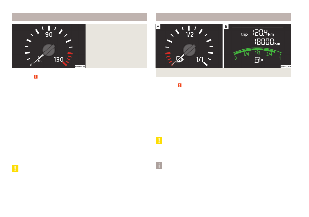
Fig. 4
Coolant temperature gauge
First read and observe the introductory information and safety warnings on page 8.
The coolant temperate display » Fig. 4 only works when the ignition is switched
on.
In vehicles with a segment display, the coolant temperature is indicated only by
the lighting up or going out of one of the warning lights » page 14, Coolant.
Cold range
If the pointer is still in the left area of the scale it means that the engine has not
yet reached its operating temperature. Avoid high speeds, full throttle and high
engine loads. This prevents possible damage to the engine.
The operating range
The engine has reached its operating temperature as soon as the pointer moves
into the mid-range of the scale. At very high ambient temperatures or heavy engine loads, the pointer may move even further to the right.
High temperature range
If the pointer reaches the red area of the scale, the coolant temperature is too
high. Further information » page 14, Coolant.
CAUTION
Additional headlights and other attached components in front of the air inlet impair the cooling efficiency of the coolant.
10
Using the system
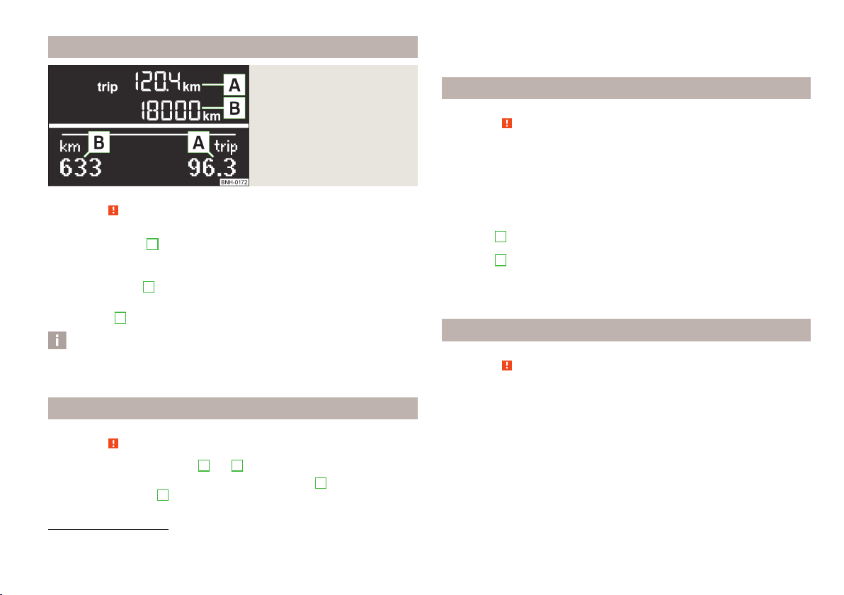
Fig. 5 Fuel gauge
First read and observe the introductory information and safety warnings
The instrument cluster can have one of the following types of fuel gauge » Fig. 5.
Instrument cluster with the MAXI DOT display
Instrument cluster with the segment display
The fuel gauge only works if the ignition is switched on.
The fuel tank has a capacity of about 55 litres. The warning light lights up when
the amount of fuel reaches the reserve zone » page 18.
The reserve zone is indicated by the red area of the scale» Fig. 5 - or by display-
ing only the last two segments of the scale » Fig. 5 - .
on page 8.
CAUTION
Never drive until the fuel tank is completely empty! The irregular supply of fuel
can cause misfiring. This can result in considerable damage to parts of the engine
and the exhaust system.
Note
After filling up, it can occur that during dynamic driving (e.g. numerous curves,
braking, driving downhill and climbing a steep hill) the fuel gauge indicates ap-
prox. a fraction less. When stopping or during less dynamic driving, the fuel gauge
displays the correct fuel level again. This is not a fault.
Page 13
Counter for distance driven
In vehicles equipped with the MAXI DOT display, it is also possible to set the clock
in the Time menu » page 26.
Fig. 6
Segment display / MAXI DOT display
First read and observe the introductory information and safety warnings on page 8.
Daily trip counter (trip)
The daily trip counter A» Fig. 6 indicates the distance which you have driven
since it was last reset - in steps of 100 metres or 1/10 of a mile.
Reset trip counter for the distance driven
Press and hold the 6 » Fig. 2 on page 8 button.
›
Odometer
The odometer
B
» Fig. 6 indicates the total distance the vehicle has travelled.
Note
If the second speed display is enabled on vehicles with a segment display, this
speed will be shown instead of the odometer.
Digital clock
First read and observe the introductory information and safety warnings on page 8.
The clock is set with the buttons 5 and 6 » Fig. 2 on page 8.
Select the display that you wish to change with the button 5 and carry out the
change with the button
6
.
Display of the second speed
First read and observe the introductory information and safety warnings on page 8.
The display can show the current speed in mph1).
This feature is provided for driving in countries with different speed units.
MAXI DOT display
The display of the second speed can be set in the menu item settings » page 26,
Settings.
Segment display
Press the 5» Fig. 2 on page 8 key repeatedly, until the odometer display flash-
›
es » page 11.
Press the 6 key while the display flashes.
›
The second speed is displayed instead of the odometer.
The display of the second speed can be disabled in the same way.
Auto Check Control
First read and observe the introductory information and safety warnings on page 8.
Vehicle condition
Certain functions and conditions of individual vehicle systems are checked continuously when the ignition is switched on and also while driving.
Some error messages and other information are displayed in the MAXI DOT display. The messages are displayed simultaneously with the symbols in the MAXI
DOT display or with the warning lights in the instrument cluster » page 12.
1)
For models with the speedometer in mph, the second speed is displayed in km/h.
Instruments and Indicator Lights
11
Page 14
The menu item Vehicle status is shown in the main menu of the MAXI DOT display whenever at least one fault message exists. After selecting this menu, the
first of the error messages is displayed. If there are several error messages, the
display will show 1/3, for example, below the message. This indicates that the
first of a total of three error messages is being displayed.
Warning symbols in the MAXI DOT display
Problem with the engine oil pressure
If the symbol is shown in the MAXI DOT display, you must have your vehicle
checked immediately by a specialist garage. The information about the maximum
permissible engine speed is displayed together with this symbol.
Clutches of the automatic gearbox are too hot
A symbol in the MAXI DOT display indicates that the temperature of the automatic gearbox clutches is too high.
The following message is shown in the MAXI DOT display.
do not continue to drive! Stop the vehicle, switch off the engine, and wait until
the icon goes out – risk of gearbox damage! You can continue your journey as
soon as the symbol disappears.
Engine oil pressure too low » page 14
Clutches of the automatic gearbox are too
hot
Check engine oil level,
engine oil sensor faulty
Problem with the engine oil pressure » page 12
Gearbox overheated. Stop! Log book!
» page 12
» page 14
WARNING
If you have to stop for technical reasons, then park the vehicle at a safe distance from the traffic, switch off the engine and activate the hazard warning
light system » page 41.
Note
■
If the MAXI DOT display shows warning messages, these messages must be
confirmed in order to access the main menu » page 20, Using the information
system .
■
As long as the operational faults are not rectified, the symbols are always indicated again. After they are displayed for the first time, the symbols continue to be
indicated without any extra messages for the driver.
Warning Lights
Introduction
This chapter contains information on the following subjects:
Handbrake
Braking system 13
Seat belt warning light
Generator
Open door 14
Engine oil 14
Coolant 14
Power steering
Electronic Stability Control (ESC)
Traction Control System (ASR)
Antilock brake system (ABS) 16
The rear fog light 16
Bulb failure
Exhaust inspection system
Glow plug system (diesel engine) 17
EPC fault light (petrol engine)
Diesel particle filter (diesel engine)
Fuel reserve
Airbag system
Tyre pressure 18
Windscreen washer fluid level
Turn signal system
Fog lights
13
13
13
15
15
15
16
16
17
17
18
18
18
19
19
12
Using the system
Page 15
Cruise control system 19
Selector lever lock
Main beam 19
The warning lights show certain functions/faults and may be accompanied by audible signals.
WARNING
■
If illuminated warning lights and the corresponding descriptions and warning notes are not observed, this may result in severe injuries or major vehicle
damage.
■
The engine compartment of your car is a hazardous area. There is a risk of
injuries, scalding, accidents and fire when working in the engine compartment, e.g. inspecting and replenishing oil and other fluids. It is essential to observe safety notes » page 155, Engine compartment.
Handbrake
First read and observe the introductory information and safety warnings
The warning light comes on if the handbrake is applied. An audible warning is
also given if you drive the vehicle for at least 3 seconds at a speed of more than
6 km/h.
The following message is shown in the MAXI DOT display.
Release parking brake!
Braking system
The indicator light illuminates if the brake fluid level in the braking system is
too low or there is a fault in the ABS.
The following message is shown in the MAXI DOT display.
Brake fluid: Log book!
on page 12.
First read and observe the introductory information and safety warnings on page 12.
Stop the vehicle, switch off the engine, and check the level of the brake fluid » page 163.
19
WARNING
■
If you have to stop for technical reasons, then park the vehicle at a safe distance from the traffic, switch off the engine and activate the hazard warning
light system » page 41.
■
The following guidelines should be observed when opening the bonnet and
checking the brake fluid level » page 155, Engine compartment.
■
If the warning light is displayed simultaneously with warning light
» page 16, Antilock brake system (ABS), do not continue your jour-
ney! Seek help from a specialist garage.
■
A fault to the ABS system or the braking system can increase the vehicle's
braking distance – risk of accident!
Seat belt warning light
First read and observe the introductory information and safety warnings
The indicator light comes on after the ignition is switched on as a reminder for
the driver and front passenger to fasten the seat belt. The indicator light only
goes out if the driver or front passenger has fastened his seat belt.
If the seat belt has not been fastened by the driver or front passenger, a permanent warning signal sounds at vehicle speeds greater than 20 km/h and simultaneously the indicator light flashes.
If the seat belt is not fastened by the driver or front passenger during the next
90 seconds, the warning signal is deactivated and the indicator light lights up
permanently.
on page 12.
Generator
First read and observe the introductory information and safety warnings on page 12.
If the warning light lights up when the engine is running, the vehicle battery is
not being charged.
Seek help from a specialist garage. The electrical system requires checking.
Instruments and Indicator Lights
13
Page 16

WARNING
If you have to stop for technical reasons, then park the vehicle at a safe distance from the traffic, switch off the engine and activate the hazard warning
light system » page 41, Hazard warning light system.
CAUTION
If the warning light (cooling system fault) lights up in addition to the warning light while driving, do not continue to drive! Stop the engine - there is a
risk of engine damage!
Open door
First read and observe the introductory information and safety warnings on page 12.
The warning light comes on if one or several doors are opened or if the boot lid
is opened.
WARNING
If you have to stop for technical reasons, then park the vehicle at a safe distance from the traffic, switch off the engine and activate the hazard warning
light system » page 41.
Engine oil
First read and observe the introductory information and safety warnings on page 12.
The warning light lights up red (low oil pressure)
The following message is shown in the MAXI DOT display.
Oil pressure: Log book!
Stop the vehicle, switch off the engine, and check the level of the engine
oil » page 160.
Even if the oil level is correct, do not drive any further if the warning light is
flashing. Also do not leave the engine running at an idling speed.
Seek help from a specialist garage.
The warning light lights up yellow (oil quantity too low)
The following message is shown in the MAXI DOT display.
Check oil level!
Stop the vehicle, switch off the engine, and check the level of the engine
oil » page 160.
The warning light will go out if the bonnet is left open for more than 30 seconds.
If no engine oil has been replenished, the warning light will come on again after
driving about 100 km.
The warning light flashes yellow (engine oil level sensor faulty)
The following message is shown in the MAXI DOT display.
Oil sensor: Workshop!
If the engine oil level sensor is faulty, the warning light flashes several times
and an audible signal sounds when the ignition is turned on.
Seek help from a specialist garage.
WARNING
If you have to stop for technical reasons, then park the vehicle at a safe dis-
tance from the traffic, switch off the engine and activate the hazard warning
lights » page 41.
Coolant
First read and observe the introductory information and safety warnings on page 12.
The indicator light lights up until the engine reaches operating temperature1).
Avoid high speeds, full throttle and high engine loads.
If the warning light lights up or flashes, either the coolant temperature is too
high or the coolant level is too low.
1)
Applies to vehicles with a segment display.
14
Using the system
Page 17

The following message is shown in the MAXI DOT display.
ENGINE COOLANT PLEASE CHECK Log book!
Stop the vehicle, switch off the engine, check the level of the coolant » page 162,
and refill the coolant if necessary » page 163.
If the coolant is within the specified range, the increased temperature may be
caused by an operating problem at the radiator fan. Check the fuse for the radiator fan, replace if necessary » page 192, Fuses in the engine compartment.
Do not continue driving if the warning light does not go off even though the
coolant level is correct and the fuse for the fan is in working order!
Seek help from a specialist garage.
WARNING
■
If you have to stop for technical reasons, then park the vehicle at a safe distance from the traffic, switch off the engine and activate the hazard warning
light system » page 41.
■
Carefully open the coolant expansion bottle. If the engine is hot, the cooling
system is pressurized – risk of scalding! It is therefore best to allow the engine
to cool down before removing the cap.
■
Do not touch the radiator fan. The radiator fan may switch itself on automatically even if the ignition is off.
Power steering
First read and observe the introductory information and safety warnings on page 12.
If the indicator light lights up, there is a fault in the power steering system.
The power steering operates with reduced steering assist or does not function at
all.
Seek help from a specialist garage.
Electronic Stability Control (ESC)
First read and observe the introductory information and safety warnings on page 12.
The warning light flashes to show that the ESC is currently operating.
If the warning light comes on immediately after you start the engine, the ESC
might be switched off due to technical reasons. Switch the ignition off and on
again. If the indicator light does not light up after you switch the engine back
on, the ESR is fully functional again.
If the warning light lights up there is a fault in the ESC system.
The following message is shown in the MAXI DOT display.
Error: Electronic Stability Control (ESC)
or
Error: Traction control (ASR)
Seek help from a specialist garage.
Further information » page 107, Electronic Stability Control (ESC).
Note
If the vehicle's battery has been disconnected and reconnected, the warning light
comes on after switching on the ignition. The warning light should go out after
driving a short distance.
Traction Control System (ASR)
First read and observe the introductory information and safety warnings on page 12.
The warning light flashes to show that the ASR is currently operating.
If the warning light comes on immediately after starting the engine, the ASR
can be switched off for technical reasons. Switch the ignition off and on again. If
the warning light does not light up after you switch the engine back on, the
ASR is fully functional again.
If the warning light lights up, there is a fault in the ASR.
Instruments and Indicator Lights
15
Page 18

The following message is shown in the MAXI DOT display.
Error: Traction control (ASR)
Seek help from a specialist garage.
Further information » page 108, Traction Control System (TCS).
Note
If the vehicle's battery has been disconnected and reconnected, the indicator
light comes on after switching on the ignition. The indicator light should go out
after driving a short distance.
Antilock brake system (ABS)
First read and observe the introductory information and safety warnings
If the warning light lights up, there is a fault in the ABS.
The following message is shown in the MAXI DOT display.
Error: ABS
The vehicle will only be braked by the normal brake system without the ABS.
Seek help from a specialist garage.
on page 12.
WARNING
■
If you have to stop for technical reasons, then park the vehicle at a safe distance from the traffic, switch off the engine and activate the hazard warning
lights » page 41.
■
If the warning light » page 13 is displayed together with warning light
do not continue your journey! Seek help from a specialist garage.
■
A fault to the ABS system or the braking system can increase the vehicle's
braking distance – risk of accident!
The rear fog light
First read and observe the introductory information and safety warnings on page 12.
The warning light comes on when the rear fog lights are operating » page 41.
Bulb failure
First read and observe the introductory information and safety warnings
The warning light comes on if a bulb is faulty:
within a few seconds of the ignition being switched on;
›
when a light with a defective bulb is turned on.
›
The following message, for example, may be shown in the MAXI DOT display.
INFORMATION Check front right low beam!
on page 12.
Note
The rear side lights and the licence plate lighting have several light bulbs. The indicator light only lights up if all light bulbs of the licence plate lighting or the
parking light (in one rear light) are defective. For this reason, regular check that
these light bulbs are working correctly.
Exhaust inspection system
First read and observe the introductory information and safety warnings on page 12.
If the warning light lights up, there is a fault in the exhaust inspection system.
The engine control unit allows the vehicle to run in emergency mode.
Seek help from a specialist garage.
16
Using the system
Page 19

Glow plug system (diesel engine)
First read and observe the introductory information and safety warnings on page 12.
The warning light comes on after the ignition has been switched on. The en-
gine can be started immediately after the pre-glow warning light goes out.
There is a fault in the glow plug system if the warning light does not come on
at all or lights up continuously.
If the warning light begins to flash while driving, a fault exists in the engine
control. The engine control unit allows the vehicle to run in emergency mode.
Seek help from a specialist garage.
EPC fault light (petrol engine)
First read and observe the introductory information and safety warnings on page 12.
If the warning light
control unit allows the vehicle to run in emergency mode.
Seek help from a specialist garage.
Diesel particle filter (diesel engine)
First read and observe the introductory information and safety warnings
The diesel particulate filter separates the soot particles from the exhaust. The
soot particles collect in the diesel particulate filter where they are burnt on a reg-
ular basis.
If the indicator light lights up, soot has accumulated in the filter.
In order to clean the filter, and where traffic conditions permit »
should be driven at an even speed of at least 60 km/h at engine speeds of 1 800 -
2 500 rpm for at least 15 minutes or until the warning light goes out with the 4th
or 5th gear engaged (automatic gearbox: position S) when the traffic situation
permits it.
lights up, there is a fault in the engine control. The engine
on page 12.
, the vehicle
The indicator light only goes out after the diesel particulate filter has been
successfully cleaned.
If the filter is not properly cleaned, the warning light does not go out and the
warning light begins to flash.
The following message is shown in the MAXI DOT display.
Diesel particulate filter: Log book!
The engine control unit allows the vehicle to run in emergency mode. After
switching the ignition off and on again the indicator light, the indicator light
also lights up.
Seek help from a specialist garage.
WARNING
■
The diesel particle filter achieves very high temperatures. Therefore do not
park in areas where the hot filter can come into direct contact with dry grass
or other combustible materials – there is the risk of fire!
■
Always adjust your speed to suit weather, road, region and traffic conditions. The recommendations indicated by the warning light must not tempt
you to disregard the national regulations for road traffic.
CAUTION
As long as the warning light lights up, one must take into account an increased fuel consumption and in certain circumstances a power reduction of the
engine.
Note
■
To assist the combustion process of the soot particles in the filter, we recom-
mend that regularly driving short distances be avoided.
■
Using diesel fuel with an increased sulphur content can considerably reduce the
lifespan of the filter. A ŠKODA service partner will be able to tell you which countries use diesel fuel with a high sulphur content.
■
If the engine is turned off during the filter cleaning process or shortly after-
wards, the cooling fan may turn on automatically for a few minutes.
Instruments and Indicator Lights
17
Page 20
Fuel reserve
First read and observe the introductory information and safety warnings on page 12.
The indicator light will come on if the fuel level is less than 7 litres.
The following message is shown in the MAXI DOT display.
Please refuel. Range: ... km
Note
The text in the display goes out only after refuelling and driving a short distance.
Airbag system
First read and observe the introductory information and safety warnings on page 12.
If the warning light lights up, there is a fault in the airbag system.
The following message is shown in the MAXI DOT display.
Error: Airbag
The operational capability of the airbag system is monitored electronically, including when one of the airbags is switched off.
If a front, side or head airbag or belt tensioner has been switched off using the
vehicle system tester:
The indicator light lights up for around 4 seconds after the ignition is switch-
›
ed on and then flashes for around 12 seconds.
The following message is shown in the MAXI DOT display.
Airbag/belt tensioner deactivated.
If the air bag was switched off using the key-operated switch on the side of the
dash panel on the passenger side:
The indicator light comes on for around 4 seconds after the ignition has been
›
switched on.
Airbags that are switched off are indicated in the middle of the dashboard by
›
the warning light
in the display
» Fig. 123 on page 136.
WARNING
If there is a fault, have the airbag system checked immediately by a specialist
garage. Otherwise, there is a risk of the airbag not being activated in the
event of an accident.
Tyre pressure
First read and observe the introductory information and safety warnings on page 12.
The warning light lights up, if there is a substantial drop in inflation pressure in
one of the tyres. Check and adjust the pressure in all tyres » page 168.
If the indicator light lights up, there is a fault in the system.
Seek help from a specialist garage.
Further information » page 171, Tyre pressure monitor.
Note
If the battery has been disconnected, the warning light illuminates after the ignition is switched on. The warning light should go out after driving a short distance.
Windscreen washer fluid level
First read and observe the introductory information and safety warnings on page 12.
If the windscreen washer fluid level is too low, the warning light comes on.
The following message is shown in the MAXI DOT display.
Top up wash fluid!
Top up with liquid » page 158, Windscreen washer system.
18
Using the system
Page 21

Turn signal system
First read and observe the introductory information and safety warnings on page 12.
Either the left or right warning light flashes depending on the position of the
turn signal lever.
If a turn signal light fails, the warning light flashes at twice its normal rate.
Switching off the hazard warning light system is switched on will cause all of the
turn signal lights as well as both warning lights to flash.
Further information » page 40, Turn signal and main beam.
Fog lights
First read and observe the introductory information and safety warnings
The warning light comes on when the fog lights are operating » page 40.
Cruise control system
The warning light comes on when the cruise control is operating » page 110.
Selector lever lock
If the warning light lights up, operate the brake pedal. This is necessary, to be
able to move the selector lever from position P or N » page 98.
on page 12.
First read and observe the introductory information and safety warnings on page 12.
First read and observe the introductory information and safety warnings on page 12.
Main beam
First read and observe the introductory information and safety warnings on page 12.
The warning light comes on when the main beam or headlight flasher are selected » page 40.
Instruments and Indicator Lights
19
Page 22
Information system
Driver information system
Introduction
This chapter contains information on the following subjects:
Using the information system
Ice warning 21
Gear recommendation 22
Door, boot lid or bonnet warning 22
Compass display 22
The information system provides the driver with alerts and messages about individual vehicle systems. This information and advice is shown in the instrument
cluster display or indicated by the lighting up of the corresponding warning light
in the instrument cluster.
Using the information system
20
The information system provides the following information.
Ice warning » page 21.
›
Recommended gear » page 22.
›
Door, boot lid or bonnet warning » page 22.
›
Compass display » page 22.
›
Multi-function display (MFA) » page 22.
›
Warning against excessive speed » page 24.
›
MAXI DOT display » page 25.
›
Service interval display » page 26.
›
Auto Check Control » page 11.
›
Selector lever positions for an automatic gearbox » page 97.
›
WARNING
Concentrate fully at all times on your driving! As the driver, you are fully responsible for the operation of your vehicle.
First read and observe the introductory information and safety warnings on page 20.
On vehicles with a segment display of the multi-function display
(MFA) » page 22 the information system can be controlled with the lever.
On vehicles with a MAXI DOT display » page 25 the information system can be
operated with the control lever and the buttons on the multifunction steering
wheel.
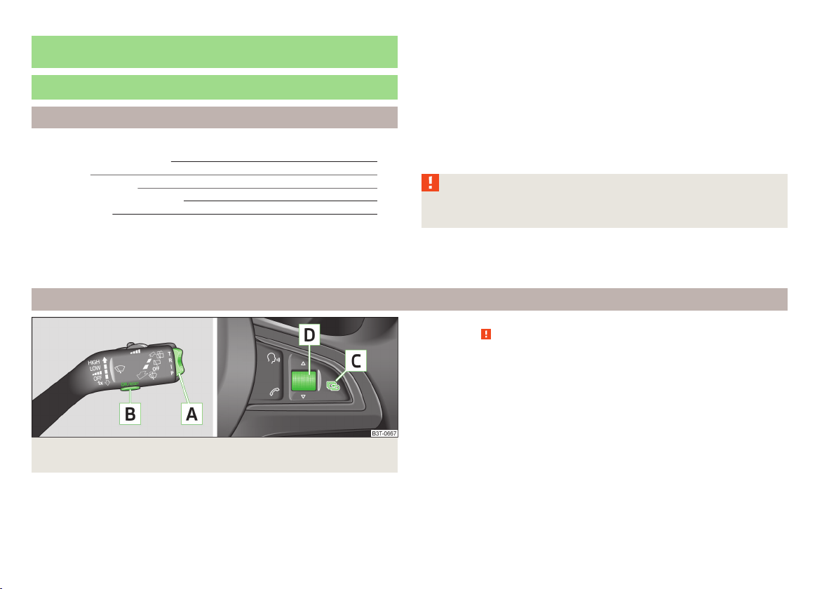
Fig. 7 Buttons/dial: on the operating lever / on the multifunction steering
wheel
20
Using the system
Page 23
Description of the operation
Button/wheel Action Operation
push up or down briefly Select data
A
B
C
D
push up or down briefly Set data values
Press and hold button Call up main menu of the MAXI DOT display
press briefly Show data
press briefly Confirm data
Press and hold button Call up main menu of the MAXI DOT display
press briefly to go back one level in the menu of the MAXI DOT display
Turn upwards or downwards Select data
Turn upwards or downwards Set data values
press briefly Show data
press briefly Confirm data
Ice warning
First read and observe the introductory information and safety warnings on page 20.
Prompt in the MAXI DOT display
If the outside temperature while driving drops to below +4°C, the following icon
appears on the display in front of the temperature display . An audible signal is
emitted.
If the outside temperature is already below +4°C when turning the ignition on,
the icon appears immediately. An audible signal is emitted.
Prompt in the segment display
If the outside temperature while driving drops to below +4°C, the temperature
display » page 24, Outside temperature will show up with the following icon in
front . An audible signal is emitted.
If the outside temperature is already below +4°C when turning the ignition on,
the temperature display and the icon appear immediately. An audible signal is
emitted.
After pressing button
last is indicated.
1)
Applies to vehicles with the multifunction display (MFA).
1)
A
» Fig. 7 on page 20, the information which was shown
WARNING
Even at temperatures around +4 °C, black ice may still be on the road surface!
You should therefore not only rely on the outside temperature display for accurate information as to whether there is ice on the road.
Information system
21
Page 24
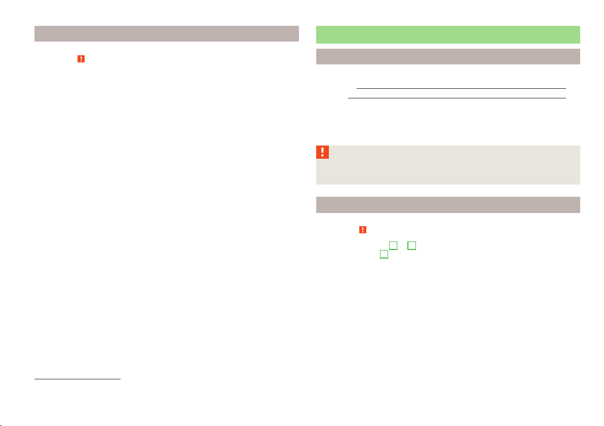
Gear recommendation
Fig. 8
Information on the selected
gear / Gear recommendation
First read and observe the introductory information and safety warnings on page 20.
Information on the selected gear
The currently engaged gear A is shown in the display » Fig. 8.
Recommended gear
In order to minimise the fuel consumption, a recommendation for shifting into another gear is indicated in the display.
1)
If the system recognises that it is beneficial to change gear, an arrow
played. The arrow points up or down, depending on whether you should shift into
a higher or lower gear.
Specification
The gear recommendation is intended only for vehicles with a manual transmis-
sion or for vehicles with an automatic transmission in manual shift mode (Tiptronic).
C
displays the recommended gear.
B
is dis-
CAUTION
The driver is always responsible for selecting the correct gear in different driving
situations, such as overtaking.
Door, boot lid or bonnet warning
First read and observe the introductory information and safety warnings on page 20.
Vehicles with a MAXI DOT display
If at least one door, the boot or bonnet is open, the display indicates the relevant
open door, boot or bonnet vehicle icon.
An acoustic signal will also sound if you drive the vehicle above 6 km/h.
Vehicles with a segment display
If at least one door or the tailgate is open, the warning light in the instrument
cluster lights up » page 14.
Compass display
First read and observe the introductory information and safety warnings on page 20.
For vehicles with a factory fitted navigation system, an abbreviation for each
point of the compass (depending on the current direction of travel) is shown on
the top left-hand corner of the 2)display.
The abbreviation for each point of the compass is displayed only when the ignition is on.
Multifunction display (MFA)
Introduction
This chapter contains information on the following subjects:
Memory 23
Information overview 24
Warning against excessive speeds
The driving data is displayed on the multifunction display.
25
1)
On vehicles with a segment display, the B arrow is displayed behind the C specification.
2)
Applies to vehicles using the MAXI DOT display.
22
Using the system
Page 25
The multifunction display can only be operated when the ignition is switched on.
After the ignition is switched on, the function that was last selected before
switching off the ignition is displayed.
For vehicles with a MAXI DOT display, the menu item MFA must be selected and
confirmed in the main menu » page 25, MAXI DOT display.
On vehicles with a MAXI DOT display, there is an option to fade out some of the
information » page 26, Settings.
WARNING
■
Concentrate fully at all times on your driving! As the driver, you are fully re-
sponsible for the operation of your vehicle.
■
Even at temperatures of around +4 °C, black ice may still be on the road surface! You should therefore not only rely on the outside temperature display
for accurate information as to whether there is ice on the road.
Note
■
In certain national versions the displays appear in the Imperial system of meas-
ures.
■
If the display of the second speed is activated in mph, the current speed is not
indicated in km/h on the display.
■
The amount of fuel consumed will not be indicated.
Memory
Fig. 9
Multi-function display - Display example of the memory
First read and observe the introductory information and safety warnings on page 22.
The multifunction display is equipped with two automatic memories, 1 and 2. The
selected memory is shown in the Display » Fig. 9.
Single-trip memory (memory 1)
The single-trip memory collates the driving information from the moment the ignition is switched on until it is switched off. New data will also flow into the calculation of the current driving information if the trip is continued within 2 hours
after switching off the ignition. If the trip is interrupted for more than 2 hours,
the memory is automatically erased.
Total-trip memory (memory 2)
The total trip memory collates the data from any number of individual trips up to
a total of 19 hours and 59 minutes or a 1999 km distance or, for vehicles with a
MAXI DOT display, 99 hours and 59 minutes, or a 9999 km distance. The memory
is deleted when either of these limits is reached and the calculation starts all over
again.
Unlike the single-trip memory, the total-trip memory is not deleted after a period
of interruption of driving of 2 hours.
Select memory
Select the corresponding element of the multi-function display » page 20, Using
›
the information system.
Press button B or the adjustment wheel D» Fig. 7 on page 20 briefly.
›
Reseting
Select the corresponding element of the multi-function display » page 20, Using
›
the information system.
Select the desired memory.
›
Press and hold button B or adjustment wheel D » Fig. 7 on page 20.
›
The following values of the selected memory are set to zero.
Average fuel consumption.
›
Distance driven.
›
Average speed.
›
Driving time
›
Note
All information in the memory
connected.
1 and 2 is erased if the battery of the vehicle is dis-
Information system
23
Page 26

Information overview
First read and observe the introductory information and safety warnings on page 22.
Outside temperature
The current outside temperature is displayed.
For vehicles with a MAXI DOT display this information is always shown.
Driving time
The driving time which has elapsed since the memory was last erased appears in
the display. If you want to measure the time travelled from a particular moment in
time, reset the memory to zero at that point in time » page 23, Memory.
The maximum time indicated in both memories is 19 hours and 59 minutes and on
vehicles which are fitted with a MAXI DOT display, it is 99 hours and 59 minutes.
The indicator is set back to zero if this period is exceeded.
Current fuel consumption
The current fuel consumption level is displayed in litres/100 km1). You can use this
information to adapt your driving style to the desired fuel consumption.
The display appears in litres/hour if the vehicle is stationary or driving at a low
speed2).
Average fuel consumption
The average fuel consumption since the memory was last erased is displayed in
litres/100 km1).
If you wish to determine the average fuel consumption over a certain period of
time, you must set the memory at the start of the new measurement to
zero » page 23, Memory. After erasing the memory, no value is displayed until you
have driven approx. 300 m.
The display is updated regularly while you are driving.
Range
The estimated range is displayed in kilometres. It indicates the distance you can
still drive with your vehicle based on the level of fuel in the tank and the same
style of driving.
The display is shown in steps of 10 km. After lighting up of the indicator light
the display is shown in steps of 5 km.
The fuel consumption over the last 50 km is used to calculate the information.
The range will increase if you drive in a more economical manner.
If the memory is set to zero (after disconnecting the battery), a fuel consumption
of 10 l./100 km is calculated for the range; afterwards the value is updated according to the style of driving.
Distance travelled
The distance travelled since the memory was last erased is displayed » page 23,
Memory. If you want to measure the distance travelled from a particular moment
in time, reset the memory to zero at that moment in time » page 23, Memory.
The maximum distance indicated in both memories is 1 999 km or 9 999 km on
vehicles with a MAXI DOT display. The indicator is set back to zero if this period is
exceeded.
Average speed
The average speed since the memory was last erased is displayed in km/
hour » page 23, Memory. To determine the average speed over a certain period of
time, set the memory to zero at the start of the measurement » page 23, Memory.
After erasing this data, no value appears in the display until you have driven approx. 300 m.
The display is updated regularly while you are driving.
Current speed
The current speed, which is identical to the display of the speedometer
on page 8 is displayed.
Oil temperature
The current engine oil temperature is displayed. If the oil temperature is lower
than 50 °C or if a fault in the system for checking the oil temperature is present,
the following is displayed instead of the oil temperature.
Warning against excessive speeds
The warning that the speed limit is being exceeded can be enabled / disabled » page 25, Warning against excessive speeds in the display.
3
» Fig. 2
1)
On some models in certain countries, the display appears in kilometres/litre.
2)
On some models in certain countries, – -.- km/ltr. is displayed when the vehicle is stationary.
24
Using the system
Page 27
Warning against excessive speeds
First read and observe the introductory information and safety warnings on page 22.
Adjust the speed limit while the vehicle is stationary
Select the menu item Speed warning (MAXI DOT display) or (segment dis-
›
play).
Activate the speed limit option by confirming this menu item1).
›
Set the desired speed limit, e.g. 50 km/h.
›
Store the speed limit by confirming the set value, or wait several seconds; your
›
settings will be saved automatically.
The speed limit can be adjusted from 30 km/h to 250 km/h in 5 km/h increments.
Adjusting the speed limit while the vehicle is moving
Select the menu item Speed warning (MAXI DOT display) or (segment dis-
›
play).
Drive at the desired speed, e.g. 50 km/h.
›
Confirm the current speed as the speed limit.
›
If you wish to adjust the set speed limit, you can do so in 5 km/h intervals (e.g. the
accepted speed of 47 km/h increases to 50 km/h or decreases to 45 km/h).
Store the speed limit, or wait several seconds; your settings will be saved auto-
›
matically.
Change or disable speed limit
Select the menu item Speed warning (MAXI DOT display) or (segment dis-
›
play).
By confirming the stored value, the speed limit is disabled.
›
By reconfirming, the option to change the speed limit is activated.
›
If the set speed limit is exceeded, an audible signal will sound as a warning. The
menu item Speed warning (MAXI DOT display) or (Segment display) appears in
the display at the same time as the set threshold.
The set speed limit value remains stored even after switching off the ignition.
MAXI DOT display
Introduction
This chapter contains information on the following subjects:
Main menu
Settings 26
The MAXI DOT display provides you with information on the current operating
state of your vehicle. It also provides you with data relating to the radio, mobile
phone, multifunction display (MFA), navigation system, automatic gearbox » page 97 and devices connected via the MDI input.
WARNING
Concentrate fully at all times on your driving! As the driver, you are fully responsible for the operation of your vehicle.
Main menu
First read and observe the introductory information and safety warnings
Press and hold button A or C » Fig. 7 on page 20 to activate the MAIN MENU. By
briefly pressing the C button you will reach one level higher.
Overview of the menu items in the main menu.
■
MFA (Multifunction display) » page 22
■
Audio » Operating instructions for the radio
■
Navigation » Operating instructions for the navigation system
■
Phone » page 80;
■
Vehicle status » page 11
■
Settings » page 26
The Audio and Navigation menu items are only displayed when the factory-fitted
radio or navigation system is switched on.
on page 25.
25
1)
If no value is set the output value 30 km/h is automatically displayed.
Information system
25
Page 28

Note
■
If warning messages are displayed, these messages must be verified to access
the main menu » page 20, Using the information system.
■
If the display is not activated at that moment, the menu always shifts to one of
the higher levels after approx. 10 seconds.
■
Using the factory-fitted radio or navigation system » Radio operating instruc-
tions or» navigation system operating instructions.
Alt. speed dis.
Here, the display of the second speed in mph1) can be activated.
Service
Here you can have the remaining kilometres and days until the next service interval displayed, and reset the Service Interval Display.
Factory setting
Here, the factory settings of the display can be restored.
Settings
First read and observe the introductory information and safety warn-
on page 25.
ings
You can change certain settings by means of the MAXI DOT display. The current
menu item is shown in the top of the display under a line.
You can select the following menu options.
Language
You can set the language for the display texts here.
MFD data
Activate or deactivate certain displays of the multifunction display here.
Time
The time, time format (12 or 24 hour indicator) and the changeover between summer/winter time can be set here.
Winter tyres
Here, you can set the speed at which an audible signal should sound. This function is, for example, used for winter tyres where the maximum permissible speed
is lower than the maximum speed of the vehicle » page 168, Tyres and wheel
rims.
The following message appears in the display when exceeding the speed limit:
Winter tyres: maximum ... km/h.
Units of measurement
The units for the temperature, consumption and distance driven can be set here.
1)
For models with the speedometer in mph, the second speed is displayed in km/h.
Service Interval Display
Introduction
This chapter contains information on the following subjects:
Prompt in the segment display
Prompt in the MAXI DOT display 27
Before the next service interval is reached, a message concerning the kilometres
and days remaining until the next service is due is shown for about 10 seconds
after the ignition is switched on.
The kilometre indicator or the days indicator reduces in steps of 100 km or, where
applicable, days until the service due date is reached.
Note
■
Information is retained in the Service Interval Display even after the vehicle bat-
tery is disconnected.
■
If the instrument cluster is exchanged after a repair, the correct values must be
entered in the counter for the Service Interval Display. This work is carried out by
a specialist garage.
■
For more information on the service intervals, see » Service schedule, chapter Service intervals.
27
26
Using the system
Page 29
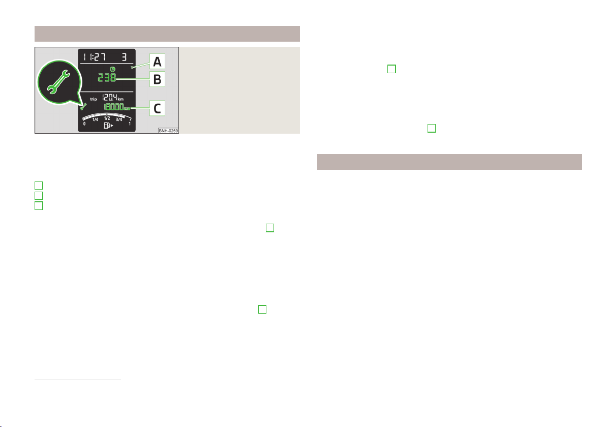
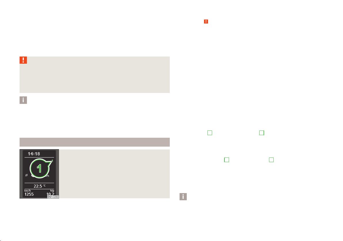
Prompt in the segment display
Fig. 10
Segment display: Example of a
message
First read and observe the introductory information given on page 26.
Explanation of graphic
service interval due
A
Distinction of the type of service
B
Icon and the days remaining until the next service interval
C
Kilometres remaining until the next service interval
Oil change service
If an oil change interval is due, the icon and the number 1 in position
played for approx. 10 seconds » Fig. 10.
The days and kilometres remaining until the next service interval are displayed at
the same time.
As soon as the due date for the service is reached, the flashing icon and the
message OIL CHNG appears in the display for about 20 seconds after the ignition
has been switched on.
Inspection
Is an inspection is due, then the icon and the number 2 in position
played for approx. 10 seconds » Fig. 10.
The days and kilometres remaining until the next service interval are displayed at
the same time.
1)
A
is dis-
A
is dis-
As soon as the due date for the service is reached, the flashing key symbol and
the text INSPEC _ appears in the display for about 20 seconds after the ignition
has been switched on.
Display the days and distance until the next service interval
You can press button 5 » Fig. 2 on page 8 continuously to display the remaining
distance and days until the next service interval whenever the ignition is switched on.
The symbol and the distance and days remaining until next service interval appear in the display for about 10 seconds.
The distance and the days remaining until the next oil change interval are displayed first; after pressing button
until the next inspection are displayed.
5
again, the distance and the days remaining
Prompt in the MAXI DOT display
First read and observe the introductory information given on page 26.
Oil change service
If an oil change interval is due, the message Oil change in ... km or ... appears
days.
As soon as the service interval date has arrived, the message Oil change now! appears once the ignition has been switched on.
Inspection
If an inspection is due, the message Inspection in ... km or ... appears days.
As soon as the service interval date has arrived, the message Inspection now! ap-
pears once the ignition has been switched on.
Displaying the distance and days until the next service interval
You can display the remaining distance and days until the next service interval
whenever the ignition is switched on in menu Settings » page 26.
The following message is displayed for 10 seconds.
Oil change ... km / ... days
Inspection ... km / ... days
1)
The kilometres remaining until the next service interval are displayed instead of the odometer.
Information system
27
Page 30
Unlocking and opening
Unlocking and locking
Introduction
This chapter contains information on the following subjects:
Vehicle key
Unlocking/locking with the key 29
unlock/lock with the remote control 30
Safelock system 30
Individual settings 31
Locking/unlocking the vehicle from the inside 31
Child safety lock
Opening/closing a door 32
Your car is equipped with a central locking system.
The central locking system allows you to lock and unlock all doors, the fuel filler
flap1) and tailgate at the same time.
The safe securing system » page 30 is integrated in the central locking system.
Once the car is locked from the outside, the door locks are automatically blocked
by the safe securing system »
The following is true after unlocking
The doors, the boot lid and the fuel filler flap1) are unlocked.
›
The interior light, which is switched by the door contact, comes on.
›
The safe securing system is switched off.
›
The indicator light in the driver door stops flashing.
›
The anti-theft alarm system is deactivated2).
›
The following is true after locking
The doors, the boot lid and the fuel filler flap1) are locked.
›
The interior lights connected over the door contact go off.
›
The safe securing system is switched on.
›
.
29
32
The warning light in the driver door begins flashing.
›
The anti-theft alarm system is activated2).
›
Displaying an error
If the indicator light in the driver's door initially flashes quickly for around 2 seconds, and then lights up for 30 seconds without interruption before flashing
again slowly, you will need to seek the assistance of a specialist garage.
WARNING
■
If the car is locked and the safe securing system is activated, there must not
be any person in the car as it is then not possible to open either a door or a
window from the inside. The locked doors make it more difficult for rescuers
to get into the vehicle in an emergency – risk to life!
Note
■
In the event of an accident in which the airbags are deployed, the locked doors
are automatically unlocked in order to enable rescuers to gain access to the vehicle.
■
Only the driver's door can be unlocked or locked using the key if the central
locking system fails » page 29. The other doors and the tailgate can be emergency locked or emergency released.
■
Emergency locking of the door » page 187.
■
Emergency unlocking of the boot lid » page 187.
■
Locked doors prevent unwanted entry into the vehicle from outside, for exam-
ple at road crossings.
1)
Applies to vehicles with a lockable fuel filler cap.
2)
Applies to vehicles with an anti-theft alarm system.
28
Using the system
Page 31

Vehicle key
Fig. 11 Key: without/with remote control
First read and observe the introductory information and safety warnings
Two keys are provided with the vehicle » Fig. 11.
Keys without remote control
Remote control key
The transmitter with the battery is housed in the handle of the remote control
key. The receiver is located in the interior of the vehicle. The operating range of
the remote control key is approx. 30 m. But this range of the remote control can
be reduced if the batteries are weak.
The remote control key has a fold-open key bit which can be used for unlocking
and locking the car manually and also for starting the engine.
The spare key must by initialised by a specialist garage after repair or replacement of the receiver unit. Only then can the remote control key be used again.
on page 28.
WARNING
■
Always withdraw the key whenever you leave the vehicle – even if it is only
for a short time. This is particularly important if children are left in the vehicle.
Otherwise, children might start the engine or operate electrical equipment
(e.g. power windows) – risk of injury!
■
Do not withdraw the ignition key from the ignition lock until the vehicle has
come to a stop. The steering lock might otherwise engage unintentionally –
risk of accident!
CAUTION
■
Each key contains electronic components; therefore it must be protected
against moisture and severe shocks.
■
Keep the groove of the keys absolutely clean. Impurities (textile fibres, dust,
etc.) have a negative effect on the functionality of the locking cylinder and ignition lock.
■
The battery must be replaced if the central locking or anti-theft alarm system
does react to the remote control at less than approx. 3 metres away » page 186.
Note
If you lose a key, please contact a specialist garage, which will be able to provide
you with a new one.
Unlocking/locking with the key
Fig. 12
Left side of the vehicle: Turning
the key for unlocking and locking the vehicle
First read and observe the introductory information and safety warnings
Unlocking
Turn the key in the locking cylinder of the driver's door in the direction of travel
›
(unlocking position)
Locking
Turn the key in the locking cylinder of the driver's door in the opposite direction
›
of travel (lock position) B » Fig. 12.
If the driver's door has been opened, the vehicle cannot be locked.
on page 28.
A
» Fig. 12.
Unlocking and opening
29
Page 32

unlock/lock with the remote control
Fig. 13
Remote control key
First read and observe the introductory information and safety warnings on page 28.
Explanation of graphic
Unlocking the vehicle
Locking the vehicle
Unlocking the boot lid
A
Folding out/folding up of the key bit
B
Warning light
Unlocking
The turn signal lights flash twice as confirmation that the vehicle has been unlocked.
If you unlock the vehicle and do not open a door or the boot lid within the next 30
seconds, the vehicle will lock again automatically and the safelock system or antitheft alarm system will be switched on. This function is intended to prevent the
car being unlocked unintentionally.
Locking
The turn signal lights flash once as confirmation that the vehicle has been locked.
If the doors or the boot lid remain open after the vehicle has been locked, the
turn signal lights do not flash until they have been closed.
Checking the battery condition
The battery is empty if the red warning icon
press a button on the remote control key. Replace the battery » page 186.
B
» Fig. 13 does not flash when you
WARNING
If the car is locked from the outside and the safelock system is switched on,
there must not be any person in the car as it is then not possible to open either a door or a window from the inside. The locked doors make it more difficult for rescuers to get into the vehicle in an emergency – risk to life!
CAUTION
■
Only operate the remote control when the doors and boot lid are closed and the
vehicle is in your line of sight.
■
If the driver door is open, the vehicle cannot be locked using the remote control
key.
■
Operation of the remote control may temporarily be affected by signal interference from transmitters close to the car and which operate in the same frequency
range (e.g. mobile phone, TV transmitter).
Note
For vehicles with an anti-theft alarm system, the acoustic signals can also be activated/deactivated when locking/unlocking at a ŠKODA partner
Safelock system
First read and observe the introductory information and safety warnings
The door locks are blocked automatically if the vehicle is locked from the outside.
Afterwards, it is not possible to open the doors with the door handle either from
the inside or from the outside.
This fact is pointed out by the following message on the display of the instrument
cluster after switching off the ignition.
Check SAFELOCK! Owner's manual!
CHECK SAFELOCK
If the vehicle is locked and the safe securing system is switched off, the door can
be opened separately from the inside by a single pull on opening lever.
Switching off
The safelock can be switched off by locking twice within 2 seconds.
on page 28.
30
Using the system
Page 33

Switching on
The safelock switches on automatically the next time the vehicle is locked and
unlocked.
Switch-on display
The warning light flashes for around 2 seconds in quick succession, afterwards it
begins to flash evenly at longer intervals.
Switch-off display
The indicator light in the driver door flashes for about 2 seconds fast, goes out
and starts to flash at longer intervals after about 30 seconds.
Locking/unlocking the vehicle from the inside
Fig. 14
Central locking button
Individual settings
First read and observe the introductory information and safety warnings on page 28.
Opening a single door
This function makes it possible to only unlock the driver's door. The other doors
remain locked and are only unlocked when the command is repeated.
Automatic locking/unlocking
All doors are locked from a speed of around 15 km/h. The button in the handle of
the boot lid is deactivated.
If the ignition key is withdrawn, the car is then automatically unlocked again. In
addition, it is possible for the driver or front passenger to unlock the car by pressing the central locking button .
The vehicle doors can be unlocked and opened at any time by pulling once on the
door opening lever.
Note
Individual settings can be carried out in a specialist workshop.
First read and observe the introductory information and safety warnings on page 28.
If the vehicle was not locked from the outside, you can also unlock or lock it with
the button » Fig. 14 without the ignition switched on. While a door is opened, the
vehicle cannot be locked.
Locking
Press the button » Fig. 14.
›
The icon inside the button comes on.
Unlocking
Press the button » Fig. 14.
›
The icon inside the button is no longer illuminated.
The following applies if your vehicle has been locked using the central locking
button.
It is not possible to open the doors or the boot lid from the outside (safety fea-
›
ture, e.g. when stopping at traffic lights etc.).
The doors can be unlocked and opened from the inside by a single pull on the
›
opening lever of the respective door.
In the event of an accident in which the airbags are deployed, the locked doors
›
are automatically unlocked from the inside in order to enable rescuers to gain
access to the vehicle.
Unlocking and opening
31
Page 34

WARNING
■
Doors locked from the inside make it difficult for rescuers to get into the ve-
hicle in an emergency – risk to life!
■
Never leave children in the vehicle unattended.
Note
If the safelock system is switched on » page 30, the door opening lever and the
central locking buttons do not work.
Opening/closing a door
Child safety lock
Fig. 15
Parental Control: Left rear door
First read and observe the introductory information and safety warnings on page 28.
The child safety lock prevents the corresponding rear door from being opened
from the inside. The door can only be opened from the outside.
You can switch the child safety lock on and off using the vehicle key.
Switching on
Turn the slot of the safety lock in the direction of the arrow » Fig. 15 (mirror-
›
inverted on the right doors).
Switching off
Turn the slot of the safety lock in the opposite direction to the arrow » Fig. 15
›
(mirror-inverted on the right door).
32
Using the system
Fig. 16 Door handle/door opening lever
First read and observe the introductory information and safety warnings
Opening from the outside
Unlock the vehicle and pull the door handleA » Fig. 16 on the door you wish to
›
open.
Opening from the inside
Pull on door opening lever B of the respective door and push the door away
›
from you.
Closing from the inside
Grasp pull handle C and close the door.
›
on page 28.
WARNING
■
Make sure that the door has closed correctly as it can open suddenly while
driving – risk of death!
■
Only open and close the door when there is no one in the opening/closing
range – risk of injury!
■
An opened door can close automatically if there is a strong wind or the vehi-
cle is on an incline – risk of injury!
Page 35

Anti-theft alarm system
Introduction
This chapter contains information on the following subjects:
Activating/deactivating
Interior monitor and towing protection 33
The anti-theft alarm system (hereinafter referred to only as alarm system) increases protection against break-in attempts into the vehicle.
The alarm system triggers audible and visual signals if an attempt is made to
break into the vehicle (hereafter referred to only as alarm).
An alarm is triggered when the following monitored areas of the vehicle have a
fault.
Bonnet.
›
Boot lid.
›
Doors.
›
Ignition lock.
›
Vehicle inclination » page 33.
›
Interior of car » page 33.
›
A drop in voltage of the on-board power supply.
›
Socket of the factory-fitted towing device » page 120, Driving with a trailer.
›
An alarm is immediately triggered if either of the two battery terminals is disconnected while the alarm system is activated.
The alarm is switched off by unlocking the vehicle or switching on the ignition.
CAUTION
Before leaving the vehicle, check that the doors and windows are closed in order
to ensure that the anti-theft alarm system is fully operational.
Note
The working life of the alarm siren is 5 years.
Activating/deactivating
First read and observe the introductory information and safety warnings on page 33.
Activating
The alarm system is activated automatically approximately 30 seconds after the
33
vehicle is locked.
If you unlock the vehicle and do not open a door or the boot lid within the next 30
seconds, the vehicle will lock again automatically and the safelock system or
alarm system will be switched on. This function is intended to prevent the car being unlocked unintentionally.
Deactivating
The alarm system is deactivated automatically after the vehicle is unlocked. If the
vehicle is not opened within 30 seconds, the alarm system is automatically activated again.
Note
If the vehicle is unlocked by inserting the key into the driver door, the key must
be inserted into the ignition lock and the ignition switched on within 15 seconds
of unlocking the door to deactivate the alarm system.
Interior monitor and towing protection
Fig. 17
Button for interior monitor and
towing protection
First read and observe the introductory information and safety warnings
The interior monitor detects movements inside the car or the inclination of the
vehicle, and then triggers the alarm.
on page 33.
Unlocking and opening
33
Page 36

Deactivating
Switch off the ignition.
›
Open the driver door.
›
Press the symbol button » Fig. 17 on the B-pillar on the driver's side. The
›
lighting of the symbol in the button changes from red to orange.
Lock the vehicle within 30 seconds.
›
The interior monitor and the towing protection are activated automatically after
the vehicle is locked.
Deactivate the interior monitor and the towing protection if there is a possibility
of the alarm being triggered by movement (e.g. children or animals) from within
the vehicle interior or if the vehicle has to be transported (e.g. by train or ship) or
towed.
CAUTION
■
The opened glasses storage compartment reduces the effectiveness of the interior monitor. To ensure the full functionality of the interior monitor, the glasses
storage compartment must always be closed before locking the vehicle.
■
The alarm system is activated when the vehicle is locked when the safelock
system is activated. The interior monitor is however not activated.
Luggage compartment lid
Introduction
This chapter contains information on the following subjects:
Open / close
Automatic locking 35
WARNING
■
Ensure that the lock is properly engaged after closing the boot lid. Otherwise, the boot lid might open suddenly while the vehicle is moving, even if it
was locked – risk of accident!
■
Never drive with the boot lid open or unlatched, as otherwise exhaust gases
may get into the interior of the vehicle – risk of poisoning!
■
Do not press on the rear window when closing the luggage compartment lid,
as otherwise it could crack – risk of injury!
35
CAUTION
■
If the vehicle was locked before the boot lid was closed, the lid is immediately
locked automatically when closed.
■
Do not press on the rear window when closing the tailgate, it could crack.
Note
The function of the button in the grip above the licence plate is deactivated when
starting off or at a speed of 5 km/hour or more for vehicles with central locking.
The function is restored after the vehicle stops and the door is opened.
34
Using the system
Page 37

Open / close
Fig. 18 Handle of boot lid
Fig. 19
Handle in the inner panelling of
the boot lid
Automatic locking
First read and observe the introductory information and safety warnings on page 34.
If the vehicle was locked before the boot lid was closed, the lid is immediately
locked automatically when closed.
The period after which the boot lid is locked automatically can be extended by a
specialist garage.
Delayed locking
If the tailgate was locked using the symbol button on the remote control key,
it is possible to open the tailgate within a limited period of time.
There is a risk of unwanted entry into the vehicle before the boot lid is locked automatically. The vehicle should therefore always be locked with the symbol button on the radio remote control.
Delayed locking can be deactivated by a specialist garage at any time.
Note
More detailed information about this is available from a ŠKODA Partner.
Electrical power windows
First read and observe the introductory information and safety warnings
After unlocking, the boot lid can be opened with the button in the handle above
the number plate.
Opening
Press the button in handle 1» Fig. 18 and lift the flap in arrow direction 2.
›
Closing
Pull the lid down with handle 3 » Fig. 19 and close with a slight swing.
›
on page 34.
Introduction
This chapter contains information on the following subjects:
Opening/closing the windows
Force limit
The electrical power windows can only be operated when the ignition is switched
on.
Unlocking and opening
36
37
35
Page 38

WARNING
■
Ensure that no persons are still left in the vehicle when locking it. In an
emergency, it will no longer be possible to open the windows from the inside.
■
It is recommended to deactivate the electrical power windows in the rear
doors (safety pushbutton) S » Fig. 20 on page 36 when children are being
transported on the rear seats.
■
The electrical power windows are fitted with a force limiter » page 37. If
there is an obstacle, the closing process is stopped and the window goes
down by several centimetres. However, the windows should be closed carefully – risk of injury!
Opening/closing the windows
CAUTION
■
Keep the windows clean to ensure the correct functionality of the electric win-
dows.
■
In the event that the windows are frozen, first of all eliminate the
ice » page 146, Windows and exterior mirrors and only then operate the electrical
power windows. Otherwise, the window sealing and the electrical power window
mechanism could be damaged.
■
Make sure that the windows are closed whenever you leave the locked vehicle.
For the sake of the environment
At high speeds, you should keep the windows closed to prevent unnecessarily
high fuel consumption.
Note
When driving always use the existing heating, air conditioning and ventilation
system for ventilating the interior of the vehicle. If the windows are opened, dust
as well as other dirt can get into the vehicle and in addition the wind noise is
more at certain speeds.
36
Using the system
Fig. 20 Buttons on the driver's door/in the rear doors
First read and observe the introductory information and safety warnings
Opening
The window can be opened by pressing lightly on the corresponding button.
›
The opening process stops when one releases the button.
Additionally, the driver's window can be opened automatically (fully open) by
pressing the button to the stop. Renewed pressing of the button causes the window to stop immediately.
Closing
The window can be closed by pulling lightly on the top corner of the corre-
›
sponding button. The closing process stops when one releases the button.
Buttons for the power windows » Fig. 20.
A
Button for electrical power window of the driver's door
B
Button for electrical power window of the front passenger door
C
Button for power window at the rear right door
D
Button for power window at the rear left door
S
Safety pushbutton
Safety pushbutton
The buttons for electrical power windows in the rear doors can be deactivated by
pressing the safety pushbutton
windows at the rear doors are activated again by pressing the safety push-button
S
again.
on page 35.
S
» Fig. 20. The buttons for the electrical power
Page 39

If the buttons for the rear doors are deactivated, the warning light in the safe-
ty switch S lights up.
Note
The window lift mechanism is equipped with protection against overheating. Re-
peated opening and closing of the window can cause this mechanism to over-
heat. If this happens, it will not be possible to operate the window for a short
time. You will be able to operate the window again as soon as the overheating
protection has cooled down.
Force limit
First read and observe the introductory information and safety warnings
The electrical power windows are fitted with a force limiter. It reduces the risk of
bruises or injuries when closing the windows.
If there is an obstacle, the closing process is stopped and the window opens by a
few centimetres.
If the obstacle prevents the window from being closed during the next 10 sec-
onds, the closing process is interrupted once again and the window opens by sev-
eral centimetres.
If you attempt to close the window again within 10 seconds of the window being
moved down for the second time, even though the obstacle was not yet been re-
moved, the closing process is only stopped. The force limiter is still switched on.
The force limiter is only switched off if you attempt to close the window again
within the next 10 seconds - the window will now close with full force!
If you wait longer than 10 seconds, the force limiter is switched on again.
on page 35.
Unlocking and opening
37
Page 40

Lights and visibility
Lights
Introduction
This chapter contains information on the following subjects:
Parking light and low beam
Daylight driving lights (DAY LIGHT) 39
Turn signal and main beam 40
Fog lights 40
Fog lights with the CORNER function 40
Rear fog light 41
Hazard warning light system
Parking light 42
Unless otherwise stated, the lights only work when the ignition is switched on.
On models fitted with right-hand steering the position of the controls differs
from that shown in » Fig. 21 on page 38. The symbols which mark the positions
of the controls are identical.
WARNING
■
The activation of the lights should only be undertaken in accordance with
national legal requirements.
■
The driver is always responsible for the correct settings and use of the
lights.
■
Never drive with only the side lights on! The side lights are not bright
enough to light up the road sufficiently in front of you or to be seen by other
oncoming traffic. Therefore always switch on the low beam when it is dark or
if visibility is poor.
38
Note
The headlights may mist up temporarily. When the driving lights are switched on,
the light outlet surfaces are free from mist after a short period, although the
headlight lenses may still be misted up in the peripheral areas. This mist has no
influence on the life of the lighting system.
Parking light and low beam
Fig. 21
Light switch and control dial for
headlight range adjustment
41
First read and observe the introductory information and safety warn-
Light switch positions A» Fig. 21.
Switching on the parking light or parking lights on both sides1) » page 42,
Parking light
Turn on the low beam
Switching off lights (except daytime running lights)
Switch on the front fog lamp » page 40
Switching on the rear fog light» page 41
Lights and visibility
Turning the rotary switch B from position to gradually activates the headlight beam adjustment, thereby shortening the beam of light.
ings
on page 38.
1)
1)
On vehicles with a MAXI DOT display, the parking light icon also lights up in the light switch.
38
Using the system
Page 41

The positions of the width of illumination correspond approximately to the fol-
lowing car load.
Front seats occupied, boot empty
All seats occupied, boot empty
All seats occupied, boot loaded
Driver seat occupied, boot loaded
WARNING
Always adjust the headlight beam to meet the following conditions.
■
The vehicle does not dazzle other road users, especially oncoming vehicles.
■
The beam range is sufficient for safe driving.
Note
■
We recommend you adjust the headlight beam when the low beam is switched
on.
■
If the light switch is in the position , the ignition key is removed and the driver's door is open, an audible warning signal will sound. The audible warning signal
is switched off by means of the door contact when the driver's door is closed (ignition off), however, the side lights remain on to illuminate the parked vehicle if
necessary.
■
An audible warning signal will sound if the light switch is in the or position, the ignition key is removed and the driver's door is opened.
■
If leaving the vehicle without needing the parking lights on, always turn the
light switch to position .
Daylight driving lights (DAY LIGHT)
First read and observe the introductory information and safety warnings on page 38.
The daytime running lights function provides the lighting of the front of the vehicle.
Switching on daytime running lights
Turn the light switch » Fig. 21 on page 38 to position .
›
Deactivating the daylight driving lights function
Deactivate the daylight driving lights by removing the fuse for the daylight driv-
›
ing lights » page 190, Fuses in the dash panel.
Activating the daylight driving lights function
Activate the daylight driving lights by inserting the fuse with the appropriate
›
amperage for the daylight driving lights » page 190, Fuses in the dash panel.
Deactivating daytime running lights on vehicles with the START-STOP system
Switch off the ignition.
›
At the same time, pull the turn signal light lever » Fig. 22 on page 40 towards
›
the steering wheel, push it downwards, and hold it in this position.
Switch on the ignition – wait until the left-turn signal light flashes 4x.
›
Switch off the ignition – an audible signal sounds which confirms the deactiva-
›
tion of the daytime running lights.
Release the turn signal lever.
›
Activating daytime running lights on vehicles with the START-STOP system
Switch off the ignition.
›
At the same time, pull the turn signal light lever » Fig. 22 on page 40 towards
›
the steering wheel, push it upwards, and hold it in this position.
Switch on the ignition – wait until the right-turn signal light flashes 4x.
›
Switch off the ignition – an audible signal sounds which confirms the activation
›
of the daytime running lights.
Release the turn signal lever.
›
The daytime running lights are switched on automatically if the following conditions are met:
The ignition is switched on.
The daylight driving lights function is activated.
The light switch » Fig. 21 on page 38 is in position .
Note
When the daytime running light is switched on, the side lights (neither at the
front nor the rear) and the number plate lights are not lit.
Lights and visibility
39
Page 42

Turn signal and main beam
Fig. 22
Operating lever: Turn signal and
main beam operation
Note
■
The main beam can only be switched on when the low beam lights are on.
■
The headlight flasher can be operated even if the ignition is switched off.
■
The turn signal light switches itself off automatically when driving around a
curve or after making a turn.
■
The warning light flashes at twice its normal rate if a bulb for the turn signal
light fails.
Fog lights
First read and observe the introductory information and safety warnings on page 38.
The parking light can also be controlled with the control lever » page 42.
Lever positions » Fig. 22
A
Switch on right turn signal
B
Switch on left turn signal
C
Switch on high beam (spring-tensioned position)
D
Switch off main beam or switch on headlight flasher (spring-tensioned position)
When the left or right turn signal is on, the warning light or flashes in the
instrument cluster.
When the high beam or headlight flasher is on, the warning light lights up in
the instrument cluster.
Turn signal for changing lanes - to only flash briefly, only move the lever up or
down to the pressure point and hold it in this position.
Convenience turn signal
If you only wish to flash three times, briefly push the lever to the upper or lower
pressure point and release again.
WARNING
Only turn on the main beam or the headlight flasher if other road users will
not be dazzled.
40
Using the system
Fig. 23
Light switch
First read and observe the introductory information and safety warnings on page 38.
Switching on/off
Turn the light switch to position or » Fig. 23.
›
Pull the light switch to position 1.
›
The rear fog light is switched off in the reverse order.
The warning light lights up in the instrument cluster when the fog lights are
switched on » page 12.
Fog lights with the CORNER function
First read and observe the introductory information and safety warnings on page 38.
The CORNER function lights the front fog lamp on each side of the vehicle to illuminate the area around the vehicle when turning, parking, etc.
Page 43

The CORNER function is switched on automatically if the following conditions
are met.
The turn signal is switched on or the front wheels are turned sharply to the
right or left1).
The engine is running.
The vehicle is stopped or moves at a speed of no more than 40 km/h.
The low beam is switched on.
The daytime running lights are not switched on.
The fog lights are not switched on.
The CORNER light is mainly intended to be used for illuminating the nearby environment at a broad angle in front of and beside the vehicle. It lights up and goes
out gradually.
Note
The two fog lights are switched on when you shift into the reverse gear.
Rear fog light
First read and observe the introductory information and safety warnings on page 38.
Switching on/off
Turn the light switch to position or » Fig. 23 on page 40.
›
Pull the light switch to position 2.
›
The rear fog light is switched off in the reverse order.
If the vehicle is not fitted with fog lights » page 40, the rear fog light is switched
on by turning the light switch to the position and is pulled out directly to the
2
position
The warning light lights up in the instrument cluster when the rear fog light is
switched on » page 12.
Only the rear fog light on the trailer lights up if the vehicle has a factory-fitted
towing device or a towing device from ŠKODA original accessories and it is driven
with a trailer.
. This switch can only be put into one position.
Hazard warning light system
Fig. 24
Button for hazard warning light
system
First read and observe the introductory information and safety warnings on page 38.
Switching on/off
Press the button » Fig. 24.
›
All the turn signal lights on the vehicle flash at the same time when the hazard
warning light system is switched on. The warning light for the turn signals and
the warning light in the button also flash at the same time. The hazard warning
light system can also be operated if the ignition is switched off.
If one of the airbags is deployed, the hazard warning light system will switch on
automatically.
When the turn signal is switched on while the hazard warning light system is on
(and ignition is switched on), only the turn signal light for the selected driving direction will flash while the turn signal is switched on.
CAUTION
Switch on the hazard warning light system if, for example, the following occurs.
■
You encounter a traffic congestion.
■
The vehicle has broken down.
1)
If both switch-on conditions are conflicting, for example, if the front wheels are turned to the left and
the right turn signal light is switched on, the turn signal light has the higher priority.
Lights and visibility
41
Page 44

Parking light
First read and observe the introductory information and safety warnings on page 38.
Parking light switching on
Switch off the ignition.
›
Place the control lever into position A or where applicable position B as far as
›
it can go » Fig. 22 on page 40 - the parking light on the right/left side of the
vehicle is switched on.
Switching on the side light on both sides
Turn the light switch A to position » Fig. 21 on page 38 and lock the vehicle.
›
Note
■
The parking light can only be activated if the ignition is switched off.
■
If the right or left turn signal light has been switched on and the ignition is
switched off, the parking light is not automatically switched on.
■
On vehicles with a MAXI DOT display, the icon in the light switch also lights up
when the two-sided parking light is switched on.
By pressing the B » Fig. 25 switches, the reading lights can be turned on/off.
If operation of the lights using the door contact switch is enabled (switch
A
» Fig. 25 is in the position), the light will come on when one of the following
occurs.
The vehicle is unlocked.
›
One of the doors is opened.
›
The ignition key is removed.
›
If operation of the lights with the door contact switch is enabled (switch A is the
position), the light will go off when one of the following occurs.
The vehicle is locked.
›
The ignition is switched on.
›
About 30 seconds after all the doors have been closed.
›
Note
If the interior light remains switched on when the ignition is switched off or if one
of the doors is open, the light will automatically go out after around 10 minutes.
Interior lighting – version 2
Interior light
Interior lighting at the front – version 1
Slide switchA positions » Fig. 25.
switching on
switching off (middle position)
Control with the door contact switch
42
Using the system
Fig. 25
Interior lighting at the front –
version 1
Fig. 26
Interior lighting – version 2
Slide switch positions » Fig. 26.
switching on
switching off
control using the door contact switch (middle position)
The same principles apply for interior lighting version 2 as for » page 42, Interior
lighting at the front – version 1.
Page 45

Rear interior light
Applies to vehicles without the panoramic roof.
Fig. 27
Interior lights at the rear
The rear interior light is operated together with the front interior light. When the
interior light at the front is switched on, the interior light at the rear also turns on
automatically. When the interior light at the front is switched off, the interior light
at the rear can be turned on/off as required1).
Switching on/off
Press the button » Fig. 27.
›
Rear interior light
Applies to vehicles with a panorama roof.
Fig. 28
Interior lights at the rear
The light can be operated by moving the lens into one of the following positions » Fig. 28.
switching on
switching off
control using the door contact switch (middle position)
2)
Visibility
Introduction
This chapter contains information on the following subjects:
Rear window heater
Sun visors 44
sunshade (Rapid Spaceback)
Rear window heater
Fig. 29
Dash panel: Button for rear window heater
First read and observe the introductory information given on page 43.
Switch the rear window heater on/off
When the heater is switched on, a lamp lights up inside the button.
43
44
1)
This function only applies to certain countries. In some countries, the light at the rear is controlled
independently from the light at the front.
2)
In this position, the same rules apply to this light as for the front interior light » page 42, Interior
lighting at the front – version 1.
Lights and visibility
43
Page 46

The rear window heater only operates when the engine is running.
The rear window heater switches off automatically after approx. 7 minutes.
For the sake of the environment
The heating should be switched off as soon as the window is de-iced or free from
mist. The reduced current consumption will have a favourable effect on fuel economy » page 103, Saving electrical energy.
Note
■
If the on-board voltage drops, the rear window heater switches off automatically, in order to provide sufficient electrical energy for the engine control » page 167, Automatic load deactivation.
■
If the light is flashing inside the button the heater is off due to low battery.
Sun visors
Sun visor: Driver's side/front passenger's side
Fig. 30
First read and observe the introductory information given on page 43.
The sun visor for the driver or front passenger can be pulled out of the fixture and
swivelled towards the door in the direction of the arrow 1 or 2 » Fig. 30.
The driver or front passenger sun visor has a vanity mirror A or B with a cover.
Slide the cover in the direction of arrow
3
or 4.
WARNING
The sun visors must not be swivelled towards the side windows in the deployment area of the head airbags if any objects, such as ball-point pens, etc. are
attached to them. This might result in injuries to the occupants if the head airbag is deployed.
sunshade (Rapid Spaceback)
Fig. 31
Sun screen
First read and observe the introductory information given on page 43.
The interior can be lit through the panoramic roof tinted glass (hereinafter only
referred to as sun roof). The panorama roof can be exposed or covered over with
the sun screen » Fig. 31. In order to close the panorama roof completely, the sun
screen must be pushed into its end position.
Please pay attention to the following points if you wish to transport luggage or
other items on the roof of your vehicle » page 69,
Windscreen wipers and washers
Introduction
This chapter contains information on the following subjects:
Activating the windscreen wipers and washers 45
Headlight cleaning system
in section Introduction.
46
44
Using the system
Page 47

The windshield wipers and the windshield washer system only operate if the ignition is switched on.
The rear window is wiped once automatically if the windscreen wipers are on
when reverse gear is selected.
Top up with windscreen wiper fluid » page 158.
WARNING
■
Properly maintained windscreen wiper blades are essential for clear visibility
and safe driving » page 188.
■
Do not use the windscreen washer system at low temperatures, without
heating the windscreen beforehand. Otherwise the window cleaner could
freeze on the windscreen and restrict the view to the front.
■
Replace the windscreen wiper blades once or twice a year for safety reasons. These can be purchased from a ŠKODA Partner.
CAUTION
■
In cold temperatures and during the winter, check before the journey or before
switching on the ignition that the wiper blades are not frozen to the windscreen.
If the windscreen wipers are switched on when the blades are frozen to the
windscreen, this may damage both the blades and windscreen wiper motor!
■
If the ignition is switched off while the windscreen wipers are switched on, the
windscreen wipers will continue wiping in the same mode after the ignition is
turned back on. The windscreen wipers could freeze up in cold temperatures between the time the ignition was turned off and when it was turned back on again.
■
Carefully detach frozen wiper blades from the front or rear window.
■
Remove snow and ice from the windscreen wipers before driving.
■
If the windscreen wipers are handled carelessly, there is a risk of damage to the
windscreen.
■
The ignition must not be switched on if the front windscreen wiper arms are fol-
ded out. The wiper blades would move back into their rest position and while doing so damage the paintwork of the bonnet.
Note
■
Keep the wiper blades clean. They may become soiled, e.g., with wax residues
after washing in automatic car wash systems » page 143.
■
The windscreen washer nozzles for the windscreen are heated when the en-
gine is running and the outside temperature is less than approx. +10 °C.
Activating the windscreen wipers and washers
Fig. 32
Operating lever: Windscreen
wipers and washer settings
First read and observe the introductory information and safety warnings on page 44.
Lever positions » Fig. 32
0
Wipers off
1
Interval windscreen wiping
2
slow windscreen wiping
3
rapid windscreen wiping
4
Flick windscreen wiping (spring-tensioned position)
5
Automatic wipe/wash for windscreen (spring-tensioned position)
6
Wiping the rear window pane (the windscreen wiper wipes at regular intervals after a few seconds)
7
Automatic wipe/wash for the rear window (spring-tensioned position)
A
Switch for setting the desired interval between the individual windscreen
1
wipes (
Automatic wipe/wash for windscreen
The wash system operates immediately, the windscreen wipers wipe somewhat
later.
Letting go of the lever will cause the windscreen wash system to stop and the
wiper to continue for another 1-3 wiper strokes (depending on the period of
spraying of the windscreen).
Automatic wipe/wash for the rear window
The wash system operates immediately, the windscreen wiper wipes somewhat
later.
Interval windscreen wiping)
Lights and visibility
45
Page 48

Letting go of the lever will cause the windscreen wash system to stop and the
wiper to continue for another 1-3 wiper strokes (depending on the period of
spraying of the windscreen). The lever will stay in position after releasing it 6.
Headlight cleaning system
First read and observe the introductory information and safety warnings on page 44.
After the ignition is turned on headlamps are always cleaned at the first and after
every tenth spraying of the windscreen 5 » Fig. 32 on page 45 when the low
beam or high beam is switched on.
You should remove stubborn dirt (such as insect residues) from the headlight lenses at regular intervals, for example when refuelling. The following guidelines
must be observed » page 147, Headlight lenses.
To ensure the proper operation of the cleaning system during the winter, any
snow should be removed from the washer nozzle fixtures and ice should be
cleared with a de-icing spray.
WARNING
■
Make sure that the mirror is not covered by ice, snow, mist or other objects.
■
Convex (curved outward) or aspheric exterior mirrors increase the field of vision. They do, however, make objects appear smaller in the mirror. These mirrors are therefore only of limited use for estimating distances to the following
vehicles.
■
Whenever possible use the interior mirror for estimating the distances to
the following vehicles.
Note
■
The exterior mirror heater only operates when the engine is running.
■
Do not touch the surface of the exterior mirrors if the exterior mirror heater is
switched on.
■
If the electrical exterior mirror setting fails at any time, the mirrors can be adjus-
ted by hand by pressing on the edge of the mirror surface.
■
Contact a specialist garage if there is a fault with the power setting function for
the exterior mirrors.
CAUTION
Never remove the nozzles from the headlight cleaning system by hand – risk of
damage!
Rear mirror
Introduction
This chapter contains information on the following subjects:
Interior mirror
Exterior mirror 47
46
Using the system
46
Interior mirror
First read and observe the introductory information and safety warnings on page 46.
Dimming mirror
Adjust the lever at the lower edge of the mirror towards the windshield. The
›
mirror dips.
Basic setting
Adjust the lever at the lower edge of the mirror away from the windscreen.
›
Page 49

Exterior mirror
Fig. 33 Side door - knob for the exterior mirrors: mechanical/electrical
First read and observe the introductory information and safety warnings
The movement of the mirror surface is identical to the movement of the rotary
knob.
Mechanically-adjustable mirrors
By moving the knob in the direction of the arrow, the mirror can be adjusted to
the desired position » Fig. 33 - .
Electrically-adjustable mirrors
By moving the knob in the direction of the arrow, the mirror can be adjusted to
the desired position » Fig. 33 - .
The knob can be moved into the following positions.
Adjust the left mirror
Adjust the right mirror
Switch off mirror control
Mirror heater
Folding in the exterior mirrors
The whole exterior mirror can be manually folded towards the side windows. To
put it back into its original position, it should be folded back from the side window
until it audibly clicks into place.
on page 46.
Lights and visibility
47
Page 50

Seats and useful equipment
Adjusting the seats
Introduction
This chapter contains information on the following subjects:
Adjusting the front seats
Head restraints 49
The driver's seat should be adjusted in such a way that the pedals can be fully
pressed to the floor with slightly bent legs.
The seat backrest on the driver's seat should be adjusted in such a way that the
upper point of the steering wheel can be easily reached with slightly bent arms.
Correct adjustment of the seats is particularly important:
for safely and quickly reaching the controls;
›
for a relaxed body position that reduces fatigue;
›
for achieving maximum protection from the seat belts and the airbag system.
›
WARNING
General information
■
Caution when adjusting the seat! You may suffer injuries or bruises as a re-
sult of adjusting the seat without paying proper attention.
■
The seat backrests must not be tilted too far back when driving, as this will
impair the function of the seat belts and of the airbag system – risk of injury!
■
Never carry more people than the number of seats in the vehicle.
■
Each occupant must correctly fasten the seat belt belonging to the seat.
Children must be fastened » page 138, Transporting children safely with a
suitable restraint system.
■
The front seats and head restraints must be adjusted to match the body
size at all times and the seat belt must always be fastened properly to provide
the most effective levels of protection to the passengers.
■
Do not carry any objects on the front passenger seat, except objects designed for this purpose (e.g. child seats) – risk of accident!
49
WARNING
Information for the driver
■
Only adjust the driver's seat when the vehicle is stationary – risk of accident!
■
Maintain a distance of at least 25 cm to the steering wheel. Not maintaining
this minimum distance will mean that the airbag system will not be able to
properly protect you - hazard!
■
Ensure that there are no objects in the driver's footwell, as these may get
caught in the pedal apparatus when driving or braking » page 96. You would
then no longer be able to operate the clutch, brake or accelerate.
WARNING
Information for the front seat passenger
■
Maintain a distance of at least 25 cm to the dash panel. Not maintaining this
minimum distance will mean that the airbag system will not be able to properly protect you - hazard!
■
Always keep your feet in the footwell when the car is being driven – never
place your feet on the instrument panel, out of the window or on the surfaces
of the seats. You will be exposed to increased risk of injury if it becomes necessary to apply the brake or in the event of an accident. If an airbag is deployed, you may suffer fatal injuries when adopting an incorrect seated position!
Note
After a certain time, play can develop within the adjustment mechanism of the
backrest angle.
48
Using the system
Page 51

Adjusting the front seats
Fig. 34 Controls on the seat / controls on the sport seat
Fig. 35
Adjusting the seat
First read and observe the introductory information and safety warnings
Adjusting a seat in a forward/back direction
Pull lever A » Fig. 34 (in the centre) in the direction of arrow 1 » Fig. 35 and
›
push the seat in the required direction.
The lock must click into place after you release the lever.
Adjusting height of seat
Push/pull the lever B » Fig. 34 in the direction of one of the arrows 2 » Fig. 35
›
again.
Adjusting the angle of the seat backrest
Remove the load on the seat backrest (do not lean on it), pull the lever
›
C
» Fig. 34 in the direction of arrow 3» Fig. 35 and set the desired angle of
the seat backrest with the back.
on page 48.
After releasing the lever C, the seat backrest will remain in the set position.
Head restraints
Head restraint: adjusting/removing
Fig. 36
First read and observe the introductory information and safety warnings on page 48.
Best protection is achieved if the top edge of the head restraint is at the same
level as the upper part of the head.
Setting height
Grasp the side of the head restraint with both hands and push it upwards as re-
›
quired.
To move the head restraint downwards, press and hold the safety button
›
A
» Fig. 36 with one hand and press the head restraint downwards with the
other hand.
Removing and installing head restraints
Pull the head restraint out of the seat backrest as far as the stop.
›
Press the safety button A » Fig. 36 and pull out the head restraint.
›
To re-insert the head restraint, push it far enough down into the seat backrest
›
until the locking button clicks into place.
Removing and installing rear head restraints
Pull the head restraint out of the seat backrest as far as the stop.
›
Press the locking button in the direction of arrow 1 » Fig. 36, simultaneously
›
press the locking button into the opening 2 using a flat screwdriver with a
width of maximum 5 mm and pull out the head rest.
To re-insert the head restraint, push it far enough down into the seat backrest
›
until the locking button clicks into place.
Seats and useful equipment
49
Page 52

WARNING
■
The head restraints must be correctly adjusted in order to offer effective
protection for the occupants in the event of an accident.
■
Never drive with the head restraints removed - risk of injury.
■
If the rear seats are occupied, the rear head restraint must not be in the
lower position.
Note
For the sport seats, the head restraints are integrated into the front seat backrests. These headrests cannot be adjusted by height or removed.
First read and observe the introductory information given on page 50.
The seat backrests and seats can be heated electrically.
The seat heating can only be switched on when the engine is running.
Switching on
Press the corresponding symbol button or » Fig. 37.
›
Pressing once switches the seat heating on at its maximum level.
With repeated pressing of the switch, the level of the seat heating is down-regu-
lated up to the switch-off. The level of the seat heating is indicated by the num-
ber of illuminated warning lights in the switch.
Seat features
Introduction
This chapter contains information on the following subjects:
Front seat heating
Front armrest 51
Rear armrest
Rear seat backrests 51
Front seat heating
Fig. 37
Heated front seats
50
Using the system
50
WARNING
If you have a controlled pain and/or temperature sensitivity, e.g. through medication, paralysis or because of chronic illness (e.g. diabetes), we recommend
not to use the seat heating. This can lead to burns on the back, the posterior
and the legs which are difficult to heal. If the seat heating is used, we recommend to make regular breaks in your journey when driving long distances, so
that the body can recuperate from the stress of the journey. Please consult
your doctor, who can evaluate your specific condition.
51
CAUTION
■
Do not kneel on the seats or otherwise apply concentrated pressure to them.
■
Do not turn on the seat heater if seats are not occupied.
■
Do not switch on the seat heating if the seats have objects attached to or
placed on them, for example a child seat, a bag, etc. A fault of the heating elements in the seat heating can occur.
■
If additional seat covers or protective covers are attached to the seats, do not
turn on the seat heater - there is a risk of damaging the seat covers and seat
heating.
■
Do not clean the seats using moisture » page 150.
Note
If the on-board voltage drops, the seat heating is switched off automatically, in
order to provide sufficient electrical energy for the engine control » page 167,
Automatic load deactivation.
Page 53

Front armrest
Fig. 38
Adjusting armrest
First read and observe the introductory information given on page 50.
Setting height
Lift the armrest right up in the direction of the arrow » Fig. 38 and then move it
›
back down completely.
Move the armrest into one of the 5 locking positions.
›
The armrest includes a storage compartment » page 58.
Rear armrest
Fig. 39
Fold the armrest forward
First read and observe the introductory information given on page 50.
Folding forward
Pull on the loop A » Fig. 39 and fold the armrest forward in the direction of the
›
arrow.
A cup holder may be located in the armrest » page 54.
Rear seat backrests
Opening for inserting the belt tongue: Rapid / Rapid Space Back /
Fig. 40
Fold back seat rest forward
First read and observe the introductory information given on page 50.
The luggage compartment can be increased in size by folding the seat backrests
forward. The seat backrests can be folded forward individually on vehicles with
divided rear seats.
Folding forward
Before folding the rear seats forwards, adapt the position of the front seats in
such a way that they are not damaged by the folded rear seat backrests1).
Put the belt tongue into the opening A » Fig. 40 on the respective side of the
›
vehicle – safety position.
Press the locking button B and completely fold the back seat rest forward in
›
the direction of the arrow.
1)
If the front seats are too far back, we recommend that you have the rear head restraints removed
before the seat backrests are folded forward. Store the removed head restraints in such a way that
they are not be damaged or soiled.
Seats and useful equipment
51
Page 54

Folding backwards
If you removed the head restraint, you need to reinsert it with the backrest til-
›
ted slightly forwards.
Then push the seat backrest back into the upright position until the locking but-
›
ton B clicks into place – check by pulling on the seat backrest » .
Make sure that the red pin C is hidden.
›
WARNING
■
The belts and the belt locks must be in their original position after folding
back the seat backrests – they must be ready to use.
■
The seat backrests must be securely locked in position so that no objects in
the luggage compartment can slide into the passenger compartment on sudden braking – risk of injury.
■
Ensure that the rear seat backrests are properly engaged. Only then can the
seat belt for the middle seat reliably fulfil its function.
CAUTION
Ensure that the seat belts are not damaged when operating the seat backrests.
Under no circumstances must the rear seat belts be jammed by the folded back
seat backrests.
Glasses storage box 58
Storage compartment on the passenger side 59
Clothes hook 59
Storage pockets on the front seats 60
Meshed pockets on the front seat backrests 60
WARNING
■
Do not place anything on the dash panel. These objects might slide or fall
down when driving (when accelerating or cornering) and may distract you
from concentrating on the traffic – there is the risk of an accident.
■
When driving, ensure that no objects from the centre console or from other
storage compartments can get into the driver's footwell. You would then no
longer be able to apply the brakes or operate the clutch or accelerator pedal –
risk of accident!
■
No objects should be placed in the storage compartments nor in the drinks
holders; the vehicle occupants could be endangered if there is sudden braking
or the vehicle collides with something.
■
Ash and cigarette or cigar stubs must only be discarded in ashtrays!
Car park ticket holder
Practical features
Introduction
This chapter contains information on the following subjects:
Car park ticket holder
Storage compartments in the doors
Holder for reflective vest 53
Storage compartments in centre console
Cup holders 54
Cigarette lighter
Ashtray
12-volt power outlet 56
Waste container
Multimedia holder 57
Storage compartment in the front arm rest
52
Using the system
52
53
54
55
55
56
58
Fig. 41
Parking ticket holder
First read and observe the introductory information and safety warnings on page 52.
The note holder is designed e.g. for attaching car park tickets.
Page 55

WARNING
The attached note has to always be removed before starting off in order not
to restrict the driver's vision.
Storage compartments in the doors
Holder for reflective vest
First read and observe the introductory information and safety warnings on page 52.
The holder for the reflective vest is located under the driver's seat » Fig. 43.
Fig. 43
Driver seat: High visibility vest
holder
Storage compartment: in the front door/in the rear door
Fig. 42
First read and observe the introductory information and safety warnings on page 52.
A
Storage compartment in the front doors
B
Bottle compartment in the front doors
C
Storage compartment in the rear doors
D
Bottle compartment in the rear doors
WARNING
Use the area A » Fig. 42 of the storage compartment only for storing objects
which do not project so that the effectiveness of the side airbag is not impaired.
Note
■
In area B of the storage compartment of the front doors, a bottle can be
housed with a max. content of 1.5 l.
■
In area D of the storage compartment of the rear doors, a bottle with a max.
content of 0.5 l can be stored.
WARNING
Do not put anything else except the reflective vest into the holder – otherwise it may fall out of the holder – risk of obstruction or limitation in operating
the pedal!
CAUTION
Do not put anything else except the reflective vest into the holder – risk of dam-
age to the holder.
Seats and useful equipment
53
Page 56

Storage compartments in centre console
Fig. 44 Storage compartment: front/rear
First read and observe the introductory information and safety warnings
Explanation of graphic » Fig. 44
A
Open storage compartment at the front of the centre console.
B
Open storage compartment at the rear of the centre console.
on page 52.
Cup holders
Fig. 45
Cup holder: front/rear
Fig. 46
Rear armrest: Cup holder
First read and observe the introductory information and safety warnings
Two beverage containers can be placed into the cup holder.
Explanation of graphic » Fig. 45
A
Cup holder in front centre console
B
Cup holder in rear centre console
Explanation of graphic » Fig. 46
C
Removable element
D
Removable element
You can change the size of the individual openings using the removable elements
C
and D » Fig. 46.
on page 52.
WARNING
■
Never put hot beverage containers in the cup holder. If the vehicle moves,
they may spill – risk of scalding!
■
Do not use any cups or beakers which are made of brittle material (e.g. glass,
porcelain). This could lead to injuries in the event of an accident.
CAUTION
Do not leave open beverage containers in the cup holder during the journey.
There is a risk of spilling e.g. when braking which may cause damage to the electrical components or seat upholstery.
54
Using the system
Page 57

Cigarette lighter
Ashtray
Fig. 47
Cigarette lighter
First read and observe the introductory information and safety warnings on page 52.
The cigarette lighter is located in the front centre console » Fig. 47.
Using the system
Press in the button of the cigarette lighter.
›
Wait until the button pops forward.
›
Remove the cigarette lighter immediately and use.
›
Place the cigarette lighter back into the socket.
›
WARNING
■
Take care when using the cigarette lighter! Improper usage can cause burns.
■
The cigarette lighter also operates when the ignition is switched off or the
ignition key withdrawn. Therefore never leave children unattended in the vehicle.
Note
■
The cigarette lighter socket can also be used as a 12Volt socket for electrical ap-
pliances » page 56, 12-volt power outlet.
■
Further information » page 150, Modifications, repairs and technical altera-
tions.
Fig. 48 Ashtrays: front/rear
First read and observe the introductory information and safety warnings
The ashtray can be used for discarding ash, cigarettes, cigars and the like » .
Removing
Pull out the ashtray » Fig. 48 upwards.
›
Install
Insert the ashtray vertically.
›
on page 52.
WARNING
Never place flammable objects in the ashtray – risk of fire!
CAUTION
When removing, do not hold the ashtray at the cover – risk of breakage.
Seats and useful equipment
55
Page 58

12-volt power outlet
Fig. 49
12-Volt power socket
First read and observe the introductory information and safety warnings on page 52.
The 12-Volt power socket is located in the front centre console » Fig. 49.
Using the power socket
Remove the power socket cover or the cigarette lighter.
›
Connect the plug for the electrical appliance to the socket.
›
The 12-volt power sockets and any connected appliances can also be operated
when the ignition is switched off or the ignition key is withdrawn »
.
WARNING
■
Improper use of the 12-volt power socket and the electrical accessories can
cause fires, burns and other serious injuries.
■
Never leave children unattended in the vehicle.
■
If the connected electric device becomes too hot, switch it off and discon-
nect it from the power supply immediately.
■
Only use accessories that have been tested for electromagnetic compatibility in
accordance with the applicable directives.
■
Before turning the ignition on or off, and before starting the car, switch off the
device connected to the 12-volt power socket to prevent any damage caused by
voltage fluctuations.
■
Observe the operating instructions for the connected devices!
Waste container
Waste container / open waste container
Fig. 50
CAUTION
■
The 12-volt power socket can only be used for connecting approved electrical
accessories with a total power uptake of up to 120 watt.
■
Never exceed the maximum power consumption, otherwise the vehicle's elec-
trical system can be damaged.
■
Connecting appliances when the engine is not running will drain the battery of
the vehicle!
■
Only use matching plugs to avoid damaging the 12-volt power socket.
56
Using the system
Replace bags
Fig. 51
First read and observe the introductory information and safety warnings on page 52.
The waste container can be inserted into the slots in the doors » page 53.
Insert waste container
Position the waste container at the front edge of the slot.
›
Page 59

Push the waste container to the back in the direction of arrow 1 » Fig. 50.
›
Push the waste container as required in the direction of arrow
›
Remove the waste container
Remove the waste container in the opposite direction to arrow 1 » Fig. 50.
›
Open/close waste container
Open the waste container in the direction of the arrow 3 » Fig. 50.
›
Closing takes place in reverse order.
Replace bags
Remove the waste container from the slot.
›
Push the two catches of the inner frame in the direction of arrow 4 » Fig. 51
›
out of the container body.
Pull the bag together with the inner frame down in the direction of arrow 5.
›
Remove the bag from the inside frame.
›
Pull the new bag through the frame and pull it over the frame in the direction of
›
arrow 6.
Insert the bag with the frame in the direction of arrow 7 into the container
›
body.
The two catches of the inner frame must click into place.
2.
WARNING
■
Never use the waste container as an ashtray - risk of fire!
■
Only replace the bag when the vehicle is stationary – risk of accident!
Note
We recommend that you use 20x30 cm bags.
Multimedia holder
Fig. 52
Multimedia holder
First read and observe the introductory information and safety warnings on page 52.
The multimedia holder is located in the front centre console » Fig. 52.
You can use this holder to store e.g. a mobile phone, MP3 player or similar devi-
ces.
WARNING
Never use the multimedia holder as an ashtray - risk of fire!
Seats and useful equipment
57
Page 60

Storage compartment in the front arm rest
Fig. 53 Opening the storage compartment
First read and observe the introductory information and safety warnings
Opening
Press the button A at the front of the armrest » Fig. 53.
›
Lift the lid of the storage box in the direction of the arrow.
›
Closing
Fold the lid on the storage box back in the opposite direction to the ar-
›
row » Fig. 53 until it clicks in.
on page 52.
Glasses storage box
Fig. 54
Opening the glasses storage box
First read and observe the introductory information and safety warnings on page 52.
Opening
Press on the lid of the glasses storage box in area A » Fig. 54.
›
The box folds in the direction of the arrow.
Closing
Swivel the lid on the glasses storage box in the opposite direction to that of the
›
arrow » Fig. 54until it click into place.
WARNING
■
The compartment must only be opened when removing or inserting the
spectacles and otherwise must be kept closed!
■
The open compartment restricts the driver's view - there is a danger of acci-
dents!
CAUTION
■
Do not put any heat-sensitive objects in the glasses storage box – they may be
damaged.
■
The maximum permissible load of the glasses compartment is 0.25 kg.
58
Using the system
Page 61

Storage compartment on the passenger side
Fig. 55 Open tray / control air supply
First read and observe the introductory information and safety warnings
Opening
Pull the handle of the flap in the direction of the arrow » Fig. 55 – and fold
›
down the flap.
Closing
Lift the lid upwards until it clicks into place.
›
Air supply
Use the rotary switch » Fig. 55 – to open/close the air supply.
›
Opening the air supply when the air conditioning system is switched on allows
cooled air to flow into the storage compartment.
Opening the air inlet when the air conditioning system is on causes fresh or interior air to flow into the storage compartment.
We recommend closing the air supply if it is operated in heating mode or the cooling system for the storage compartment is not being used.
on page 52.
WARNING
The storage compartment must always be closed when driving for safety reasons.
Note
■
A 1 litre bottle (max. capacity) can be stored in the storage compartment on the
front passenger's side.
■
When the storage compartment is opened, a light lights up.
Clothes hook
First read and observe the introductory information and safety warnings on page 52.
The clothes hooks are located on the middle pillar and on the handle of the headliner above each of the rear doors.
WARNING
■
Only hang light items of clothing on the hooks. Never leave any heavy or
sharp-edged objects in the pockets of the items of clothing.
■
Do not use clothes hangers for hanging up items of clothing; this may re-
duce the effectiveness of the head airbags.
■
Ensure that any clothes hanging from the hooks do not impair your vision to
the rear.
CAUTION
The maximum permissible load of the hooks is 2 kg.
Seats and useful equipment
59
Page 62

Storage pockets on the front seats
Fig. 56
Map pockets
First read and observe the introductory information and safety warnings on page 52.
The pockets intended for storage of maps, magazines, etc. are provided on the
reverse side of the front seat rests » Fig. 56.
WARNING
Never put heavy items into the map pockets – risk of injury!
CAUTION
Never put large objects into the map pockets, e.g. bottles or objects with sharp
edges - risk of damaging the pockets and seat coverings.
Meshed pockets on the front seat backrests
Fig. 57
Meshed pocket
First read and observe the introductory information and safety warnings on page 52.
Meshed pockets for storing small, lightweight objects such as mobile phones or
MP3 players can be found on the inner side of the front seat backrests » Fig. 57.
WARNING
Do not exceed the maximum permissible load of the meshed pockets. Heavy
objects are not secured sufficiently – risk of injury!
CAUTION
■
The maximum permissible load of the meshed pockets is 150 g.
■
Never put large objects into the meshed pockets, e.g. bottles or objects with
sharp edges – risk of damaging the meshed pockets.
Luggage compartment
Introduction
This chapter contains information on the following subjects:
Fastening elements
Fixing nets 62
Hooks
Luggage compartment cover 63
“Parking position” of the luggage compartment cover 64
Storage compartments in the luggage compartment
Flexible storage compartment (Rapid Spaceback)
Meshed pocket for storage (Rapid Spaceback)
Two-sided floor covering
Please observe the following for the purpose of maintaining good handling characteristics of your vehicle:
Distribute loads as evenly as possible.
›
Place heavy objects as far forward as possible.
›
Attach the items of luggage to the lashing eyes or using the nets » page 61.
›
61
62
64
65
65
65
60
Using the system
Page 63

In the event of an accident, even small and light objects gain so much kinetic energy that they can cause severe injuries.
The magnitude of the kinetic energy is dependent on the speed at which the vehicle is travelling and the weight of the object.
Example: In the event of a frontal collision at a speed of 50 km/h, an object with a
weight of 4.5 kg produces an energy, which corresponds to 20 times its own
weight. This means that it results in a weight of approx. 90 kg “ ”.
Luggage compartment light
The light comes on automatically when the boot lid is opened. If the lid remains
open for more than 10 minutes, the boot lid switches off automatically.
WARNING
■
Store the objects in the boot and attach them to the lashing eyes.
■
Loose objects can be thrown forward during a sudden manoeuvre or in case
of an accident and can injure the occupants or other road users.
■
Loose objects could hit a deployed airbag and injure occupants – danger of
death!
■
Please note that transporting heavy objects alters the handling properties
of the vehicle due to the displacement of the centre of gravity – risk of accident! The speed and style of driving must be adjusted accordingly.
■
If the items of luggage or objects are attached to the lashing eyes with unsuitable or damaged lashing straps, injuries can occur in the event of braking
manoeuvres or accidents. To prevent items of luggage from moving around,
always use suitable lashing straps that are firmly attached to the lashing eyes.
■
The transported items must be stowed in such a way that no objects are
able to slip forward on sudden driving or braking manoeuvres – risk of injury!
■
When transporting objects in the luggage compartment that has been enlarged by folding the rear seats forward, ensure the safety of the passengers
transported on the other rear seats » page 124, Correct seated position for
the passengers in the rear seats.
■
If the rear seat next to the folded forward seat is occupied, ensure maximum safety, e.g. by placing the goods to be transported in such a way that the
seat is prevented from folding back in case of a rear collision.
■
Do not drive with the luggage compartment lid open or unlatched, otherwise exhaust gases may get into the interior of the vehicle – risk of poisoning!
■
Do not exceed the permissible axle loads and permissible gross weight of
the vehicle – risk of accident!
■
Do not transport people in the boot!
CAUTION
Please ensure that the heating elements for the rear window heater are not damaged as a result of abrasive objects.
Note
Tyre pressure must be adjusted to the load » page 169, Service life of tyres.
Fastening elements
Fig. 58
Lashing eyes and fastening elements
First read and observe the introductory information and safety warnings
The boot provides the following fastening elements » Fig. 58.
A
Lashing eyes for fastening items of luggage and fixing nets.
B
Fastening element and eyelet only for fastening fixing nets » page 62.
on page 60.
CAUTION
The maximum permissible load of the lashing eyes A is 3.5 kN (350 kg).
Note
B
The front eyelet
is located behind the folding rear seat backrest » Fig. 58.
Seats and useful equipment
61
Page 64

Fixing nets
Fig. 59 Fastening examples for nets
Fig. 60
Fastening vertical pocket
First read and observe the introductory information and safety warnings
Examples for attaching the fixing nets» Fig. 59.
A
Horizontal pocket
B
Floor net
C
Vertical pocket
on page 60.
CAUTION
■
The maximum permissible load of the fixing nets is 1.5 kg.
■
Do not place any sharp objects in the nets – risk of net damage.
Hooks
Fig. 61
Hooks
First read and observe the introductory information and safety warnings
Hooks for attaching small items of luggage, such as bags etc., are provided on
both sides of the boot » Fig. 61.
on page 60.
CAUTION
The maximum permissible load of the hook is 7.5 kg.
WARNING
Do not exceed the maximum permissible load of the fixing nets. Heavy objects
are not secured sufficiently – risk of injury!
62
Using the system
Page 65

Luggage compartment cover
Fig. 62 Secure luggage compartment cover
First read and observe the introductory information and safety warnings
The boot cover can be removed if you want to transport bulky goods.
Removing
Hook the support straps A » Fig. 62 onto the tailgate.
›
On the underside of the cover, in the area between the bolts, tap B.
›
Remove the cover.
›
The dismantled luggage compartment cover can be stowed away behind the rear
seat backrest in the so called “parking position” » page 64.
Install
Place the cover on the contact surfaces of the side trim panel.
›
The mounts of the cover C » Fig. 62 must be positioned above the bolts B of
›
the side trim panel.
Interlock the cover by lightly knocking on the top side of the cover in the area
›
between the bolts.
Hook the support straps A onto the tailgate.
›
on page 60.
WARNING
No objects should be placed on the boot cover, the vehicle occupants could be
endangered if there is sudden braking or the vehicle collides with something.
CAUTION
■
The maximum permissible load of the luggage compartment cover is 1 kg.
■
Please ensure that the heating elements for the rear window heater are not
damaged as a result of objects placed in this area.
■
When closing the boot lid, jamming and damage to the luggage compartment
cover or the side trim panel can occur if handled in an unprofessional way. The
following guidelines must be observed.
■
The mounts of the cover C » Fig. 62 must be interlocked in the bolts of the
side trim panel B.
■
The items which are transported must not exceed the height of the luggage
compartment cover in the lower position.
■
The cover must not be jammed in the seal of the boot lid when it is in the
opened position.
■
There must be no object in the gap between the opened cover and the rear
backrest.
Note
■
If the retaining strips A » Fig. 62 are attached to the tailgate, the boot cover
will raise when you open the tailgate.
■
After removing the luggage compartment cover, store it in such a way that it
cannot be damaged or soiled.
Seats and useful equipment
63
Page 66

“Parking position” of the luggage compartment cover
Fig. 63 Parking position of the luggage compartment cover: Rapid / Rapid
Spaceback
First read and observe the introductory information and safety warnings on page 60.
Set-up
Rapid: Slide the dismantled cover between the rear seat back rest and bolt
›
A
» Fig. 63.
Rapid Spaceback: Slide the dismantled cover between bolt B and contact sur-
›
C
of the side panel.
face
WARNING
■
The luggage compartment cover in the “parking position” restricts the driv-
er's view at the back1).
■
The luggage compartment cover must not be between bolt B» Fig. 63 and
the rear seat backrest 2) when the “parking position” is being set.
CAUTION
■
The following information applies to Rapid Spaceback vehicles.
■
Before setting the “parking position” of the luggage compartment cover, the
variable loading floor must be put in the desired position» page 66.
■
If the luggage compartment cover is in the “parking position”, the “parking po-
sition” of the variable loading floor cannot be set » page 682).
Storage compartments in the luggage compartment
Fig. 64
Remove storage compartment
cover (Rapid)
Fig. 65 Remove storage compartment cover (Rapid Spaceback): left/right
First read and observe the introductory information and safety warnings
The side compartment covers can be removed to increase the size of the luggage
compartment.
Removing/Inserting
Grasp the top part of the cover and remove it in the direction of the ar-
›
row » Fig. 64 or » Fig. 65.
Insertion takes place in reverse order.
on page 60.
1)
Applies to Rapid.
2)
Applies to Rapid Spaceback.
64
Using the system
Page 67

CAUTION
■
The storage compartments are designed for storing small objects of up to 1.5 kg.
in weight in total.
■
When using the storage compartment, take care not to damage the storage
compartment or the luggage compartment lining.
Flexible storage compartment (Rapid Spaceback)
Fig. 66
Flexible storage compartment
First read and observe the introductory information and safety warnings on page 60.
The flexible storage compartment can be built into the right-hand side of the
boot » Fig. 66.
Installing
Place both ends of the storage compartment into the openings on the right side
›
panel of the luggage compartment.
Push the storage compartment down to lock it.
›
Removing
Grasp the storage compartment on the two upper corners.
›
Remove the storage compartment by pulling upwards and then towards you.
›
CAUTION
The storage compartment is designed for storing small objects with a maximum
total weight of 8 kg.
Note
The flexible storage compartment cannot be installed on vehicles with the variable loading floor » page 66.
Meshed pocket for storage (Rapid Spaceback)
Fig. 67
Meshed pocket for storage
First read and observe the introductory information and safety warnings
The meshed pocket for storage is located on the right side of the luggage compartment » Fig. 67.
on page 60.
CAUTION
The meshed pocket for storage is designed for storing small objects of up to 1.5
kg. in weight in total.
Two-sided floor covering
First read and observe the introductory information and safety warnings on page 60.
You can fit a double-sided floor covering in the luggage compartment.
One side of the double-sided floor covering is made of fabric, the other side is
washable (easy to maintain).
The washable side is used to transport wet or dirty items.
Seats and useful equipment
65
Page 68

CAUTION
The two-sided floor covering can only be installed in the luggage compartment of
vehicles with the variable loading floor when the variable load floor is in the upper position » page 661).
Note
For easier turning of the covering, use the loop attached.
Variable loading floor in the luggage compartment
(Rapid Spaceback)
Introduction
This chapter contains information on the following subjects:
Set to upper position
Adjust to the lower position 67
Remove/Insert
Fold up/fold down 68
“Parking position” 68
The variable loading floor makes handling of bulky items of luggage easier.
The variable loading floor can be set to the upper or lower position.
For easier handling of the spare tire, for example, the variable loading floor can be
set to two positions » page 68, Fold up/fold down and » page 68, “Parking po-
sition”.
CAUTION
The maximum permissible load of the variable loading floor is 75 kg. For the transport of heavy loads, adjust the variable loading floor to the lower position or remove it from the vehicle.
66
67
Set to upper position
Fig. 68 Set the variable loading floor to the upper position
Fig. 69
Set variable loading floor to the upper position / variable loading
floor in the upper position
First read and observe the introductory information and safety warnings
The variable loading floor in the lower position can be set to the upper position as
follows.
Grasp the variable loading floor at handle A» Fig. 68.
›
Lift the variable loading floor in the direction of arrow 1 and move partially
›
backwards in the direction of arrow
Lift the variable loading floor at the front, place onto corner C and slide in the
›
direction of arrow 3 until it clicks into place in brackets B.
on page 66.
2
.
1)
Applies to Rapid Spaceback.
66
Using the system
Page 69

Place the variable loading floor in direction of arrow 4 » Fig. 69 - .
›
CAUTION
When setting the variable loading floor to the upper position, the luggage compartment cover must not be in the “parking position” » page 64.
Note
Under the variable loading floor in the upper position » Fig. 69 - there is a
space for storing items.
Adjust to the lower position
Fig. 70 Set the variable loading floor to the lower position
Fig. 71
Set variable loading floor to the lower position / variable loading
floor in the lower position
First read and observe the introductory information and safety warnings on page 66.
The variable loading floor in the upper position can be set to the lower position as
follows.
Grasp the variable loading floor at handle A» Fig. 70.
›
Lift the variable loading floor in the direction of arrow 1 and partially move in
›
the direction of arrow 2 until it detaches from brackets B.
Place the variable loading floor onto the floor covering of the luggage compart-
›
ment while tilted forward.
Push the variable loading floor in the direction of arrow 3 all the way to the
›
stop, and until its front part
Place the variable loading floor in direction of arrow 4.
›
C
» Fig. 71 is raised.
CAUTION
When setting the variable loading floor to the lower position, the luggage compartment cover must not be in the “parking position” » page 64.
Remove/Insert
Fig. 72
Remove variable loading floor
First read and observe the introductory information and safety warnings
Removing
Grasp the variable loading floor at handle A» Fig. 72.
›
Lift the variable loading floor in the direction of arrow 1 until its rear area is
›
about 15 cm B below the luggage compartment cover » .
Remove the variable loading floor from the vehicle by moving it in the direction
›
of arrow 2.
on page 66.
Seats and useful equipment
67
Page 70

Inserting
Grasp the variable loading floor at handle A» Fig. 72.
›
Insert variable loading floor into the vehicle with the front portion tilted about
›
15 cm Bbeneath the luggage compartment cover» .
Then follow the same steps as when setting the upper position » page 66, Set
›
to upper position or the lower position » page 67, Adjust to the lower position .
Lift the variable loading floor in the direction of arrow 1 until the foldable
›
edges B lock in place in area C.
Folding down
Grasp the variable cargo floor in the middle or at handle A.
›
Unlock the variable loading floor by pulling it in direction of arrow 2 » Fig. 73.
›
CAUTION
■
When removing or inserting the variable loading floor, the maximum distance of
15 cm B» Fig. 72 under the luggage compartment cover must be adhered to -
there is a risk of damaging the boot flap seal.
■
When inserting the variable loading floor into the vehicle, the luggage compartment cover must not be in the “parking position” » page 64.
Note
After removing the variable cargo floor, place it down in such a way that it cannot
be damaged or soiled.
Fold up/fold down
Fold up/fold down variable loading floor
Fig. 73
First read and observe the introductory information and safety warnings on page 66.
The variable loading floor can be folded up in both positions (upper and lower).
Folding up
Grasp the variable loading floor at handle A» Fig. 73.
›
“Parking position”
Fig. 74 Set parking position / fold down from the parking position
First read and observe the introductory information and safety warnings
The variable loading floor can only be in set to the “parking position” when it is in
the lower position » page 67 and the luggage compartment cover has been taken
out » page 63.
Folding up
Remove the luggage compartment cover from the vehicle » page 63.
›
Grasp the variable loading floor at handle
›
Lift the variable loading floor in the direction of arrow 1 until the foldable
›
edges B lock in place in area C.
Folding down
Push the foldable corners B» Fig. 74 on both sides of the variable loading floor
›
in the direction of arrow 2 and remove these from positions C.
Grasp the variable cargo floor in the middle or at handle A.
›
Fold down the variable loading floor in the direction of arrow 3.
›
on page 66.
A
» Fig. 74.
68
Using the system
Page 71

WARNING
The variable loading floor in the “parking position” restricts the driver's view
at the back.
CAUTION
■
The variable loading floor can only be set to the “parking position” when in the
lower position.
■
If the variable loading floor is in the “parking position”, the “parking position” on
the luggage compartment cover cannot be set » page 64.
Roof rack system
CAUTION
■
Only use roof rack systems approved by ŠKODA AUTO a.s.
■
If other roof rack systems are used or if the roof bars are not fitted correctly,
any resulting damage to the vehicle is not covered by the warranty. Therefore ensure the supplied fitting instructions for the roof rack system are observed.
■
On models fitted with a power sliding/tilting roof, ensure that the extended
sliding/tilting roof does not hit any items of luggage transported on the roof.
■
Ensure that the boot lid does not hit the roof load when opened.
■
The height of the vehicle changes after mounting a roof luggage rack system
and the load that is secured to it. Compare the vehicle height with available clear-
ances, such as underpasses and garage doors.
■
Always remove the roof luggage rack system before entering an automated car
wash.
■
Ensure the roof aerial is not impaired by the secured load.
Introduction
This chapter contains information on the following subjects:
Attachment points
Roof load 70
WARNING
■
The transported items on the roof rack must be securely attached – risk of
accident!
■
Always secure the load with appropriate and undamaged lashing straps or
tensioning straps.
■
Distribute the load evenly over the roof rack system.
■
When transporting heavy objects or objects which take up a large area on
the roof rack system, handling of the car may change as a result of the displacement of the centre of gravity. The style of driving and speed must therefore be adapted to the current circumstances.
■
Avoid abrupt and sudden driving/braking manoeuvres.
■
Adjust the speed and driving style to the visibility, weather, road and traffic
conditions.
■
The permissible roof load, permissible axle loads and permissible total vehicle weight must not be exceeded under any circumstance – risk of accident!
For the sake of the environment
The increased aerodynamic drag results in a higher fuel consumption.
69
Attachment points
Fig. 75
Attachment points for roof bars
First read and observe the introductory information and safety warnings on page 69.
Installation location of the attachment points for roof bars » Fig. 75:
A
Rear attachment points
B
Front attachment points
Seats and useful equipment
69
Page 72

Perform the assembly and disassembly according to the enclosed instructions.
CAUTION
Observe the information regarding the assembly and disassembly in the enclosed
instructions.
Roof load
First read and observe the introductory information and safety warnings on page 69.
The maximum permissible roof load (including roof rack system) of 75 kg and the
maximum permissible total weight of the vehicle should not be exceeded.
The full permissible roof load cannot be used if a roof rack system with a lower
load carrying capacity is used. In this case, the roof rack system must only be loaded up to the maximum weight limit specified in the fitting instructions.
70
Using the system
Page 73

Heating and air conditioning system
Heating, ventilation, cooling
Introduction
This chapter contains information on the following subjects:
Air outlets
Using the cooling system economically 72
Operational problems 72
The heating effect is dependent upon the coolant temperature, thus full heat
output only occurs when the engine has reached its operating temperature.
If the cooling system is switched on, the temperature and air humidity drops in
the vehicle. The cooling system prevents the windows from misting up when outside temperatures are particularly low.
It is possible to briefly activate recirculated air mode to enhance the cooling effect.
Please refer to the information regarding recirculated air mode for the air-conditioning system » page 76 or for Climatronic » page 79.
WARNING
For your own safety and that of other road users, ensure that all the windows
are free of ice, snow and misting. Please familiarize yourself about how to correctly operate the heating and ventilation systems, how to demist and defrost
the windows, as well as with the cooling mode.
CAUTION
■
The air inlet in front of the windscreen must be free from ice, snow or leaves,
for example, to ensure that the heating and cooling system works properly.
■
After switching on the cooling Condensation from the evaporator of the air con-
ditioning may drip down and form a puddle below the vehicle. This is not a leak!
Note
■
The used air streams out through vents at the back of the boot.
■
We recommend that you do not smoke in the vehicle when the recirculating air
mode is operating since the smoke which is drawn at the evaporator from the interior of the vehicle forms deposits in the evaporator of the air conditioning system. This produces a permanent odour when the air conditioning system is operating which can only be eliminated through considerable effort and expense (replacement of compressor).
71
Air outlets
Fig. 76 Air outlet vents
First read and observe the introductory information and safety warnings on page 71.
Warmed, not warmed fresh or cooled air will flow out of the opened air outlet
vents according to the setting of the control dial and the outside atmospheric
conditions.
On air outlet vents 3 and 4» Fig. 76 the direction of air flow can be changed and
the vents can also be opened or closed individually and the amount of airflow adjusted.
Set the air flow direction
To adjust the height of the air flow, turn the horizontal fins with the movable
›
adjuster
A
» Fig. 76 upward or downward.
Heating and air conditioning system
71
Page 74

To adjust the lateral direction of the air flow, turn the vertical fins with the mov-
›
able adjuster A to the left or to the right.
Setting the amount of airflow
Turn knob B» Fig. 76 upwards all the way to the stop, in order to fully open the
›
air outlet.
Turn knob B downwards all the way to the stop, to close the air outlet.
›
The knob can be adjusted to any position in between.
An overview of the available settings for adjusting the direction of the air outlet.
Setting the direction of the air
outlet
Active air outlet vents
1, 2, 4
1, 2, 4, 5
4, 5
3, 4
Note
Do not cover the air outlet vents with objects of any kind.
Using the cooling system economically
First read and observe the introductory information and safety warnings on page 71.
The air conditioning system compressor uses power from the engine when in
cooling mode, which will affect the fuel consumption.
It recommended to open the windows or the doors of a vehicle for which the interior has been strongly heated through the effect of direct sunlight in order to allow the heated air to escape.
The cooling system should not be on if the windows are open.
For the sake of the environment
Pollutant emissions are also lower when fuel is being saved » page 100, Economical driving and environmental sustainability.
Operational problems
First read and observe the introductory information and safety warnings on page 71.
If the cooling system does not operate at outside temperatures higher than +5 °C,
there is a problem in the system. The reasons for this may be.
One of the fuses has blown. Check the fuse and replace if necessa-
›
ry » page 190.
The cooling system has switched off automatically for a short time because the
›
coolant temperature of the engine is too hot » page 10.
If you are not able to resolve the operational problem yourself, or if the cooler
output has reduced, switch off the cooling system and seek assistance from a
specialist garage.
Heating
Introduction
This chapter contains information on the following subjects:
Control elements 73
Adjusting 73
Recirculated air mode
74
72
Using the system
Page 75

Control elements
Fig. 77 Heating: Control elements
Adjusting
First read and observe the introductory information given on page 72.
Recommended basic settings of the heating controls.
Set-up
Defrosting the windshield and side
windows
Free windshield and side windows
from mist
The fastest heating
Comfortable heating Desired temperature 2 or 3
Fresh air mode – ventilation
To the right up to the
Desired temperature 2 or 3
To the right up to the
To the left up to the
Control dial settings » Fig. 77 on page 73
A B C
stop
stop
stop
1-4
First read and observe the introductory information given on page 72.
Functions of the individual controls » Fig. 77:
A
Set the temperature (turn to the left: to reduce the temperature: turn to the
right: increase temperature)
B
Set the blower stage (stage 0: Blower off, stage 4: the highest blower stage)
C
Set the direction of the air outlet » page 71
Switch recirculated air mode on/off » page 74
Controls A and C» Fig. 77 can be set at any position in between.
WARNING
The blower should always be on to prevent the windows from misting up.
Symbol button
3
3
Do not switch on
Do not switch on
Briefly switch on Opening
Do not switch on Opening
Do not switch on Opening
Air outlet vents 4 » Fig. 76 on
page 71
Open and align with the side win-
dow
Open and align with the side win-
dow
Heating and air conditioning system
73
Page 76

We recommend that you leave the air outlet vents 3 » Fig. 76 on page 71 in the
open position in all operating modes.
Note
If the air distribution is positioned only towards the windows, the total amount of
air is used to defrost the windows and thus no air will be fed to the footwell. This
can lead to restriction of the heating comfort.
Recirculated air mode
First read and observe the introductory information given on page 72.
Recirculated air mode mostly prevents polluted air outside the vehicle from getting into the vehicle, for example when driving through a tunnel or when standing
in a traffic jam.
Switching on/off
Press the symbol button .
›
The indicator light in the button lights up.
Press the symbol button again.
›
The indicator light in the button goes out.
Recirculated air mode is switched off automatically if the air distribution control
C
» Fig. 77 on page 73 is turned to position . Recirculated air mode can be
switched on again from this setting by repeatedly pressing the symbol button .
WARNING
Never leave recirculated air mode on over a longer period of time, as “stale air”
can cause fatigue of the driver and passengers, reduce attention levels and also cause the windows to mist up. The risk of having an accident increases.
Switch off recirculated air mode as soon as the windows start to mist up.
Air conditioning system (manual air conditioning
system)
Introduction
This chapter contains information on the following subjects:
Control elements 75
Setting 76
Recirculated air mode 76
The cooling system works only if the following conditions are met.
The cooling system is switched on » page 75.
The engine is running.
The outside temperature is above approx. +2 °C.
The blower switch is switched on (positions 1-4).
If the desired interior temperature can also be achieved without activating the
cooling system, fresh air mode should be selected.
When the coolant temperature that is too high, the cooling system is switched off
to ensure that the engine cools down.
CAUTION
■
Under certain circumstances, air at a temperature of about 5 °C can flow out of
the vents when the cooling system is switched on.
■
Lengthy and uneven distribution of the air flow out of the vents (especially
around the feet) and large differences in temperature, for example, when getting
out of the vehicle, can cause susceptible individuals to catch a cold.
Note
We recommend that you have the air conditioning system cleaned by a specialist
garage once every year.
74
Using the system
Page 77

Control elements
Fig. 78 The air conditioning system: Control elements
First read and observe the introductory information and safety warnings on page 74.
Functions of the individual controls » Fig. 78:
A
Set the temperature (turn to the left: to reduce the temperature: turn to the
right: to increase temperature)
B
Set the blower stage (stage 0: Blower off, stage 4: the highest blower stage)
C
Set the direction of the air outlet » page 71
Switch recirculated air mode on/off » page 76
Switch the cooling system on/off
Note
The warning light in the symbol button lights up after activation, even if not all
of the conditions for the function of the cooling system are met » page 74. By
lighting up of the warning light in the button, the operational readiness of the
cooling system is signalled.
Heating and air conditioning system
75
Page 78

Setting
First read and observe the introductory information and safety warnings on page 74.
Recommended basic settings of the air conditioning controls.
Set-up
Defrost/defog windscreen and
side windows
The fastest heating
Comfortable heating
The fastest cooling
Optimal cooling
Fresh air mode – ventilation
a)
We recommend that you do not use this setting in countries with high humidity levels. This can result in heavy cooling of the window glass and the following fogging from outside.
b)
Automatic activation can be turned off by pressing the symbol button .
c)
Under certain conditions, recirculated air mode » page 76 may come on automatically; the warning light will then light up in the symbol button .
We recommend that you leave the air outlet vents 3 » Fig. 76 on page 71 in the
open position in all operating modes.
a)
Recirculated air mode
First read and observe the introductory information and safety warnings on page 74.
Recirculated air mode mostly prevents polluted air outside the vehicle from getting into the vehicle, for example when driving through a tunnel or when standing
in a traffic jam.
Switching on/off
Press the symbol button .
›
Control dial settings » Fig. 78 on page 75 Symbol button » Fig. 78 on page 75
A B C
Desired tempera-
ture
To the right up to
the stop
Desired tempera-
ture
To the left up to
the stop
Desired tempera-
ture
To the left up to
the stop
3 or 4
3
2 or 3
briefly 4, then
2 or 3
1, 2 or 3
Desired position
The indicator light in the button lights up.
Press the symbol button again.
›
The indicator light in the button goes out.
Recirculated air mode is switched off automatically if the air distribution control
C
» Fig. 78 on page 75 is turned to position .
Recirculated air mode can be switched on again from this setting by repeatedly
pressing the symbol button .
Do not switch on
Briefly switch on Switched off Opening
Do not switch on Switched off Opening
Briefly switch on
Do not switch on Activated Open and align to the roof
Do not switch on Switched off Opening
Automatically switched
c)
b)
on
Activated Opening
Air outlet vents 4 » Fig. 76
on page 71
Open and align with the side
window
76
Using the system
Page 79

WARNING
Never leave recirculated air mode on over a longer period of time, as “stale air”
can cause fatigue of the driver and the passengers, reduce attention levels
and also cause the windows to mist up. The risk of having an accident increases. Switch off recirculated air mode as soon as the windows start to mist up.
Climatronic (automatic air conditioning system)
Introduction
This chapter contains information on the following subjects:
Control elements
automatic mode
Switching the cooling system on/off
Setting the temperature 78
recirculated air mode
Controlling blower 79
Defrosting windscreen
The Climatronic in automatic mode ensures the best-possible setting of the temperature of the outflowing air, the blower stage and air distribution.
The system also takes sunlight into account, which eliminates the need to alter
the settings manually.
The cooling system works only if the following conditions are met.
The cooling system is switched on » page 77.
The engine is running.
The outside temperature is above approx. +2 °C.
If the coolant temperature is too high, the cooling system is switched off to ensure that the engine cools down.
Note
We recommend that you have Climatronic cleaned by a specialist garage once every year.
Control elements
77
78
78
79
79
Fig. 79 Climatronic: Control elements
The buttons/control dial
1
Setting the interior temperature » page 78
Display
2
Display of selected interior temperature
3
Degrees Celsius or Fahrenheit, change the displayed temperature
units » page 78, Setting the temperature
4
Automatic operation of the air conditioning system
5
Ventilation or defrosting of the windshield activated
6
Direction of air flow
7
Recirculated air mode activated
8
Cooling system activated
9
Blower speed set
The buttons/control dial
10
Adjust the blower speed » page 79
11
Interior temperature sensor
Switching automatic mode on » page 78
Switch the intensive windscreen heater on/off » page 79
First read and observe the introductory information given on page 77.
Heating and air conditioning system
77
Page 80

Air flow to the windows
Air flow to the upper body
Air flow in the footwell
Switch recirculated air mode on/off » page 79
Switch the cooling system on/off » page 78
Note
Do not stick anything on or cover the interior temperature sensor 11; it could
have an unfavourable effect on the Climatronic.
automatic mode
First read and observe the introductory information given on page 77.
The automatic mode is used in order to maintain a constant temperature and to
demist the windows in the interior of the car.
Recommended setting for all periods of the year
Set the desired temperature, we recommend 22 °C.
›
Press the button
›
The display shows
Move the air outlet vents 3 and 4 » Fig. 76 on page 71 so that the air flow is di-
›
rected slightly upwards.
Automatic mode can be switched off by pressing one of the buttons for the air
distribution or by increasing/decreasing the blower speed. The temperature is
nevertheless regulated.
.
(Pos. 4» Fig. 79 on page 77).
Switching the cooling system on/off
First read and observe the introductory information given on page 77.
Press the button .
›
The display shows the icon (Pos
Once again press the button .
›
The icon in the display goes out.
8
» Fig. 79 on page 77).
After the cooling system is switched off, only the ventilation function remains active, whereby the lowest temperature that can be reached is the outside temperature.
Setting the temperature
First read and observe the introductory information given on page 77.
Setting temperature
Switch on the ignition.
›
Turn the control dial 1» Fig. 79 on page 77 to the left or to the right to increase
›
or decrease the temperature.
The set temperature value appears in the display (Pos.2» Fig. 79 on page 77).
Switching between Celsius and Fahrenheit
Press and hold the
›
The information in the desired temperature measuring unit appears in the display
(Pos. 3 » Fig. 79 on page 77).
The interior temperature can be set between +18 °C and +29 ℃. The interior temperature is regulated automatically within this range.
If you select the temperature below +18 ℃, “LO” appears in the display.
If you select a temperature higher than +29 ℃, “HI” appears in the display.
In both limit positions the Climatronic operates at maximum cooling or heating
capacity, respectively. The temperature is not automatically regulated in this case.
CAUTION
Lengthy and uneven distribution of the air flow out of the vents (especially
around the feet) and large differences in temperature, for example, when getting
out of the vehicle, can cause susceptible individuals to catch a cold.
and keys simultaneously.
78
Using the system
Page 81

recirculated air mode
First read and observe the introductory information given on page 77.
Recirculated air mode mostly prevents polluted air outside the vehicle from getting into the vehicle, for example when driving through a tunnel or when standing
in a traffic jam.
Switching on/off
Press the symbol button .
›
The display shows the icon (Pos 7» Fig. 79 on page 77).
Press the symbol button again.
›
The icon in the display goes out.
WARNING
Never leave recirculated air mode on over a longer period of time, as “stale air”
can cause fatigue of the driver and the passengers, reduce attention levels
and also cause the windows to mist up. The risk of having an accident increases. Switch off recirculated air mode as soon as the windows start to mist up.
Note
If recirculated air mode is switched on for around 15 minutes, the symbol will
begin to flash in the display as a sign that recirculated air mode is switched on
long-term. If the recirculated air mode is not switched off, the symbol flashes for
around 5 minutes.
Controlling blower
First read and observe the introductory information given on page 77.
The Climatronic system controls the blower stages automatically in line with the
interior temperature. However, the blower level can be manually adjusted to suit
your particular needs.
Turn the control dial 10 » Fig. 79 on page 77 to the left or to the right to in-
›
crease or decrease the blower speed.
If the blower is switched off, the Climatronic system is switched off.
The set blower speed is shown by displaying the corresponding number of seg-
ments in icon 9 in the display.
WARNING
■
“Stale air” may result in fatigue in the driver and occupants, reduce attention
levels and also cause the windows to mist up. The risk of having an accident
increases.
■
Do not switch off the Climatronic system for longer than necessary.
■
Switch on the Climatronic system as soon as the windows mist up.
Defrosting windscreen
First read and observe the introductory information given on page 77.
Switching on/off
Press the symbol button » Fig. 79 on page 77.
›
The display shows the icon (Pos. 5 » Fig. 79 on page 77).
Press the symbol button again or press the symbol button
›
The icon in the display goes out.
More air flows out of the air outlet vents 1 » page 71 and 2. The temperature control is controlled automatically.
.
Heating and air conditioning system
79
Page 82

Communication and multimedia
Universal telephone installation GSM II
Introduction
This chapter contains information on the following subjects:
Introductory information
Phone Phonebook 81
Control telephone from the multifunction steering wheel - Version 1 81
Control telephone from the multifunction steering wheel - Version 2 82
Symbols in the display 83
Connecting the mobile phone to the hands-free system 83
Telephone operation in the MAXI DOT display
ŠKODA permits the operation of mobile phones and two-way radio systems with
a professionally installed external aerial and a maximum transmission power of
up to 10 watts.
Please consult a ŠKODA Partner for information about the possibility of installing
and operating mobile phones and two-way radio systems with a transmission
power of more than 10 W.
Operating mobile phones or two-way radio systems may interfere with the functionality of the electronic systems in your vehicle.
The reasons for this are as follows:
no external aerial;
›
external aerial incorrectly installed;
›
transmission power greater than 10 watts.
›
WARNING
■
Concentrate fully at all times on your driving! As the driver, you are fully re-
sponsible for the operation of your vehicle.
■
The national regulations for using a mobile phone in a vehicle must be ob-
served.
80
84
WARNING (Continued)
■
If a mobile phone or a two-way radio system is operated in a vehicle without
an external aerial or an external aerial which has been installed incorrectly,
this can increase the strength of the electromagnetic field inside the vehicle.
■
Two-way radio systems, mobile phones or mounts must not be installed on
airbag covers or within the immediate deployment range of the airbags.
■
Never leave a mobile phone on a seat, on the dash panel or in any area
where it can become a projectile during a sudden braking manoeuvre, an accident or a collision — risk of injury.
■
The Bluetooth® function must be switched off by a specialist company before the vehicle can be transported by air.
Note
■
We recommend that the installation of mobile phones and two-way radio sys-
tems in a vehicle be carried out by a ŠKODA Partner.
■
Not all mobile phones that enable Bluetooth® communication are compatible
with the universal telephone preinstallation GSM II. You can ask a ŠKODA Partner
whether your telephone is compatible with the GSM II universal telephone fitting.
■
The range of the Bluetooth® connection to the hands-free system is restricted
to the vehicle interior. The range is dependent on local factors, e.g. obstacles between the devices and mutual interferences with other devices. If your mobile
phone is in a jacket pocket, for example, this can lead to difficulties when establishing a connection with the hands-free-system or transferring data.
Introductory information
First read and observe the introductory information and safety warnings on page 80.
The universal telephone preinstallation GSM II (hands-free system) includes a
convenience mode for the mobile phone via voice control, the multifunction
steering wheel, the radio or navigation system.
The universal telephone preinstallation GSM II comprises the following functions.
Phone Phonebook » page 81.
›
Convenience operation of the telephone via the multifunction steering
›
wheel » page 82.
Telephone operation in the MAXI DOT display » page 84.
›
Voice control of the telephone » page 85.
›
Music playback from the telephone or other multimedia units » page 87.
›
80
Using the system
Page 83

All communication between a mobile phone and your vehicle's hands-free system
is established with the help of Bluetooth® technology.
Phone Phonebook
First read and observe the introductory information and safety warnings on page 80.
A phone phonebook is part of the hands-free system. This phone phonebook can
be used depending on the type of mobile phone.
After the first connection of the telephone, the system begins to load the phone
book from the phone and the SIM card into the memory of the control unit.
Control telephone from the multifunction steering wheel - Version 1
Fig. 80 Multifunction steering wheel: Control buttons for the telephone
First read and observe the introductory information and safety warnings
To minimize driver distraction when operating the telephone, the basic telephone's functions can be set by simply operating the buttons located on the
steering wheel » Fig. 80.
on page 80.
Each time the telephone has established a new connection with the hands-free
system, an update of the relevant phone book is performed. The updating can
take a few minutes. During this time the phone book, which was stored after the
last update was completed, is available. Newly stored telephone numbers are on-
ly shown after the updating has ended.
The update is interrupted if a telephone event (e.g. incoming or outgoing call,
voice control dialogue) occurs during the updating procedure. After the telephone
event has ended, the updating starts anew.
The internal phonebook provides 2 500 free memory locations. Each contact can
contain up to 4 numbers.
If the number of contacts loaded exceeds 2 500, the phone book is not complete.
This applies only if your vehicle has been equipped with the universal telephone
installation at the factory.
The buttons control the functions for the operating mode of the current tele-
phone.
If the side lights are switched on, the buttons on the multifunction steering
wheel are illuminated.
Button/
wheel » Fig. 80
1
1
1
Action Operation
Press briefly Mute (MUTE )
Turn upwards Increase the volume
Turn downwards Decrease the volume
Communication and multimedia
81
Page 84

Button/
wheel » Fig. 80
2
2
3
3
3
3
3
4
4
a)
The symbol → means briefly press the button again.
Action Operation
Press briefly
Accept call, End call
Display telephone's basic menu →a) Telephone main menu → List of dialled numbers → Call selected contact
Press and hold button Reject the incoming call
Turn up/down Previous / next menu item
Press briefly Confirm selected menu item
Press and hold button Continuously display first letter of the phone book
Quickly turn upwards To the previous initial letter in the telephone book
Quickly turn downwards To the next initial letter in the telephone book
Press briefly Return to a previous level in the menu
Press and hold button Exit telephone menu
Control telephone from the multifunction steering wheel - Version 2
Fig. 81
Multifunction steering wheel:
Control buttons for the telephone
First read and observe the introductory information and safety warnings on page 80.
The driver can set the basic functions of the telephone by simply operating the
buttons located on the steering wheel so that he can concentrate on the traffic
situation without being distracted as little as possible by operating the telephone » Fig. 81.
This applies only if your vehicle has been equipped with the universal telephone
preinstallation (hands-free system) at the factory.
If the side lights are switched on, the buttons and the symbols and on the
multifunction steering wheel are illuminated.
Button/
wheel » Fig. 81
1
1
2
82
Using the system
Action Operation
Press briefly Accept call, terminate call, entry in the main menu of the telephone, list of selected numbers
Press and hold button Reject call, last number dialleda), switch voice control on/off
b)
Press briefly Switch on/off voice control
Page 85

Button/
wheel » Fig. 81
2
2
a)
Valid for vehicles with the Amundsen+ navigation system.
b)
Valid for vehicles without the Amundsen+ navigation system.
Action Operation
Turn upwards Increase the volume
Turn downwards Decrease volume
Symbols in the display
First read and observe the introductory information and safety warnings on page 80.
The following icons are shown in the information cluster display.
Symbol Importance
Charge status of the phone battery
A multimedia unit is connected to the hands-free system.
a)
This function is only supported by some mobile phones.
Signal strength
a phone is connected to the hands-free system.
The hands-free system is visible to other devices.
a)
a)
Connecting the mobile phone to the hands-free system
First read and observe the introductory information and safety warnings
To connect a mobile phone with the hands-free system, the two devices must be
paired. Detailed information on this is provided in the operating instructions for
your mobile phone.
1)
On vehicles fitted with the Amundsen+ navigation system, this function can be accessed via the navigation system menu; refer to the » operating instructions for the Amundsen+ navigation system.
2)
Depending on the Bluetooth® version on the mobile phone, an automatically generated 6-digit PIN
(SSP) is either displayed, or the PIN 1234 has to be entered manually.
3)
Some mobile phones have a menu, in which the authorisation for establishing a Bluetooth® connection is completed by inputting a PIN number. If the authorisation input is required, it must always be
performed when re-establishing the Bluetooth connection.
on page 80.
The following steps must be carried out for pairing1).
Activate Bluetooth® and the visibility of your mobile phone on your telephone.
›
Switch on the ignition.
›
Select the Phone - New user menu in the MAXI DOT display and wait until the
›
hands-free system has completed the search.
Select the phone you wish to connect from the list of units found.
›
Confirm the PIN2).
›
If the hands-free system announces (as standard SKODA_BT) on the display of
›
the mobile phone, enter the PIN2) within 30 seconds and wait, until the connection is established3).
To finish pairing in the MAXI DOT display, confirm the creation of the new user
›
profile.
If there is no free space available to create a new user profile, delete an existing
user profile.
During the connecting procedure, no other mobile phone may be connected with
the hands-free system.
Up to four mobile phones can be paired with the hands-free system, whereby on-
ly one mobile phone can communicate with the hands-free system.
The visibility of the hands-free system is automatically switched off 3 minutes af-
ter the ignition is switched on and is also deactivated when the mobile phone has
connected to the hands-free system.
Communication and multimedia
83
Page 86

Restoring the visibility of the hands-free system
If you have not managed to connect your mobile phone with the hands-free system within 3 minutes of switching on the ignition, the visibility of the hands-free
system can be re-established for 3 minutes in one of the following ways.
By turning the ignition off and on.
›
By turning voice control off and on.
›
In the MAXI DOT display under menu item Bluetooth - Visibility.
›
Creating a connection with an already paired mobile phone
After switching on the ignition, the connection is automatically established for
the already paired mobile phone1). Check on your mobile phone if the automatic
connection has been established.
Disconnecting the connection
The connection to a connected mobile phone can be ended in the following ways.
By withdrawing the ignition key.
›
By disconnecting the hands-free system in the mobile phone.
›
By disconnecting from the user in the MAXI DOT display under the menu item
›
Bluetooth - User.
Solving connection problems
If the hands-free system reports No paired phone found, check the operating
status of the mobile phone.
Is the mobile phone switched on?
›
Is the PIN code entered?
›
Is Bluetooth® active?
›
Is the visibility of the mobile phone active?
›
Has the mobile phone already been paired with the hands-free system?
›
Telephone operation in the MAXI DOT display
First read and observe the introductory information and safety warnings on page 80.
The following menu items can be selected from the Phone menu.
Telephone book
›
Dial number
›
Call lists
›
Voice mailbox
›
Bluetooth
›
Settings
›
Back
›
Telephone book
The Phone book menu item lists the contacts downloaded from the telephone
memory and the mobile phone SIM card.
Dial number
Any telephone number can be entered in the Dial number menu item. The required numbers must be selected one after the other using adjustment wheel
and confirmed by pressing the adjustment wheel. You can select digits 0-9, symbols , , # and the Cancel, Call and Delete functions.
Call lists
The following menu items can be selected in the Call list menu item.
■
Missed calls
■
Dialled numbers
■
Received calls
Voice mailbox
In the Voice mailbox menu item, you can set the number of the voice mailbox
and then dial the number.
2)
2)
3)
2)
1)
Some mobile phones have a menu, in which the authorisation for establishing a Bluetooth® connection is completed by inputting a PIN number. If the authorisation input is required, it must always be
performed when re-establishing the Bluetooth connection.
2)
On vehicles fitted with the Amundsen+ navigation system, this function can be accessed via the navigation system menu; refer to the » operating instructions for the Amundsen+ navigation system.
3)
This function is not available in vehicles fitted with the Amundsen+ navigation system.
84
Using the system
Page 87

Bluetooth
The following menu items can be selected from the Bluetooth menu item.
■
User - Overview of the stored telephones
■
New user - Search for new mobile phones that are in the reception range
■
Visibility - Switches on the visibility of the hands-free system for other devices
■
Media player - Playback via Bluetooth
■
Active device - Connected device
■
Paired devices - List of paired devices
■
Search - Device search
■
Phone name - option to change the name of the phone (default SKODA_BT)
Settings
The following menu items can be selected from the Settings menu item.
■
Telephone book - Phonebook
■
Update - Update the phone book
■
List - Arrange the entries in the phone book
■
Surname - Arrange according to surname
■
First name - Arrange according to first name
■
Ring tone - Ring tone setting
Back
Return in the Start menu of the telephone.
®
1)
Voice control
Introduction
This chapter contains information on the following subjects:
Dialogue – version 1
Dialogue – version 2 86
Voice commands
Dialogue – version 1
Fig. 82 Multifunction steering wheel: Voice control
First read and observe the introductory information given on page 85.
The period of time during which the system is ready to accept voice commands
and execute them is called dialogue. The system gives audible feedback and
guides you if necessary through the relevant functions.
Optimum voice command recognition depends on several factors.
Speak with a normal tone of voice without intonation and excessive pauses.
›
Avoid bad pronunciation.
›
Close the doors, windows and sliding roof, to reduce or stop disturbing exterior
›
noise.
It is recommended to speak louder at higher speeds, so that the tone of your
›
voice is louder than the increased surrounding noise.
During dialogue, limit additional noise in the vehicle, e.g. passengers talking at
›
the same time.
85
87
Do not speak if the system is making an announcement.
›
The microphone for voice control is inserted in the moulded headliner and direc-
ted to the driver and front passenger. Therefore the driver and the front passen-
ger can operate the equipment.
1)
On vehicles fitted with the Amundsen+ navigation system, this function can be accessed via the navigation system menu; refer to the » operating instructions for the Amundsen+ navigation system.
Communication and multimedia
85
Page 88

Entering a phone number
The telephone number can be entered as a continuous series of individually spoken digits (the whole number at once) or in the form of digital blocks (separated
by short pauses). After each order of digits (separation through brief voice pause)
all of the digits detected up to now are repeated by the system.
The digits 0-9, symbols +, , # are permitted. The system does not recognize any
combination of connected numbers, such as twenty-three for example.
Switching on voice control
By briefly pressing the button 1 » Fig. 82 on the multifunction steering wheel.
Switching off voice control
If the system is currently playing a message, the message that is currently being
played must be terminated by briefly pressing the button
ti-function steering wheel.
If the system expects a voice command, you can end dialogue yourself:
with the CANCEL voice command;
›
by briefly pressing button 1 » Fig. 82 on the multifunction steering wheel.
›
1
» Fig. 82 on the mul-
Note
■
Dialogue is immediately interrupted in the events of an incoming call.
■
Voice control is only possible in vehicles fitted with a multi-function steering
wheel with telephone control.
Dialogue – version 2
Fig. 83
Multifunction steering wheel:
Voice control
First read and observe the introductory information given on page 85.
The period of time during which the system is ready to accept voice commands
and execute them is called dialogue. The system gives audible feedback and
guides you if necessary through the relevant functions.
Optimum voice command recognition depends on several factors.
Speak with a normal tone of voice without intonation and excessive pauses.
›
Avoid bad pronunciation.
›
Close the doors, windows and sliding roof, to reduce or stop disturbing exterior
›
noise.
It is recommended to speak louder at higher speeds, so that the tone of your
›
voice is louder than the increased surrounding noise.
During dialogue, limit additional noise in the vehicle, e.g. passengers talking at
›
the same time.
Do not speak if the system is making an announcement.
›
The microphone for voice control is inserted in the moulded headliner and directed to the driver and front seat passenger. Therefore the driver and the front seat
passenger can operate the equipment.
Entering a phone number
The telephone number can be entered as a continuous series of individually spoken digits (the whole number at once) or in the form of digital blocks (separated
by short pauses). After each order of digits (separation through brief voice pause)
all of the digits detected up to now are repeated by the system.
The digits 0-9, symbols +, , # are permitted. The system does not recognize any
combination of connected numbers, such as twenty-three for example.
Switching on voice control
By briefly pressing the button 1 » Fig. 83 on the multifunction steering wheel.
Switching off voice control
If the system is currently playing a message, the message that is currently being
played must be terminated by briefly pressing button
function steering wheel.
If the system expects a voice command, you can end dialogue yourself:
with the CANCEL voice command;
›
by briefly pressing button
›
1
» Fig. 83 on the multifunction steering wheel.
1
» Fig. 83 on the multi-
86
Using the system
Page 89

Note
■
The dialogue of an incoming call is immediately interrupted.
■
The voice control is only possible in vehicles fitted with a multi-function steer-
ing wheel with telephone control.
Voice commands
First read and observe the introductory information given on page 85.
Basic voice commands
Voice command Action
HELP
CALL XYZ
PHONE BOOK
CALL HISTORY Lists of dialled numbers, missed calls, etc.
DIAL NUMBER
REDIAL
a)
MUSIC
FURTHER OPTIONS
SETTINGS Selection for setting Bluetooth®, dialogue etc.
CANCEL The dialogue is ended.
a)
On vehicles fitted with the Amundsen+ navigation system, this function can be accessed via the navigation system menu; refer to the » operating instructions for the Amundsen+ navigation system.
If a voice command is not detected, the system answers with “Sorry?” and a new
entry can be completed. After the 2nd error the system repeats the aid. After the
3rd error the answer “Cancelled” is given and the dialogue is ended.
After this command the system repeats all possible
commands.
This command calls up the contact from the phone
book.
After this command, for example, the phone book
can be repeated back to you, a voice entry for the
contact can be updated or deleted, etc.
After this command, a telephone number can be entered to establish a connection with the requested
party.
After this command the system calls the last dialled
number.
Play music from the mobile phone or another paired
device.
After this command the system offers additional
context-dependent commands.
Store voice recording of a contact
If automatic name recognition does not work reliably for some contacts, you can
choose to save your own voice tag for the contact in the Phone book - Voice tag -
Record menu item.
Your own voice entry can also be saved using the voice control in the menu FUR-
THER OPTIONS.
Multimedia
Introduction
This chapter contains information on the following subjects:
Music playback via Bluetooth
Operating the radio and navigation system on the multifunction steering
wheel - Version 1 88
Operating the radio and navigation system on the multifunction steering
wheel - Version 2
AUX-IN and MDI inputs 90
Music playback via Bluetooth
First read and observe the introductory information given on page 87.
®
®
The universal telephone preinstallation GSM II makes it possible to play back mu-
sic via Bluetooth® from the devices such as MP3 player, mobile phone or note-
book.
To ensure that music can be played via Bluetooth®, you must first pair the device
with the hands-free system in the Phone - Bluetooth - Media player menu.
The music playback process is performed on the connected device.
The universal telephone preinstallation GSM II ensures that the music played back
via the hands-free system can be controlled with the remote control » page 87,
Voice commands.
87
89
Communication and multimedia
87
Page 90

Note
The device being connected must support the Bluetooth® A2DP profile; refer to
the operating instructions for the relevant device being connected.
Operating the radio and navigation system on the multifunction steering wheel - Version 1
The radio and the navigation system can of course still be operated via the devices. A description is included in the relevant operating instructions.
If the side lights are switched on, the buttons on the multifunction steering
wheel are illuminated.
The buttons apply for the respective operating mode of the current radio, audio,
video or navigation system.
The following functions can be completed by pressing or turning the buttons.
Fig. 84 Multifunction steering wheel: Navigation control buttons
First read and observe the introductory information given on page 87.
The multifunction steering wheel comprises buttons for setting the basic functions for the factory-fitted radio and the navigation system » Fig. 84.
Button/
wheel » Fig. 84
1
2
2
2
3
3
4
4
88
Using the system
Action Radio Audio sources Navigation
Press Change audio source
Press Switch tone off/on (MUTE )
Turn upwards Increase the volume
Turn downwards Decrease the volume
Press briefly
Press and hold button No function Fast-forward No function
Press briefly
Press and hold button No function Rewind No function
Skip to next channel Skip to next track No function
Stop traffic announcement
Switch to previous channel Switch to start of track
Stop traffic announcement
a)
Interrupt current navigation announce-
ment
No function
Page 91

Button/
wheel » Fig. 84
5
5
6
a)
To go to the previous track, press the adjustment wheel twice or rotate it by two positions.
Action Radio Audio sources Navigation
Turn upwards
Turn downwards
Press briefly Call up the main menu
Switch to previous station and display
List of stored/accessible stations
Switch to the next station and display
List of stored / accessible stations
Skip to next track
Switch to start of track
Operating the radio and navigation system on the multifunction steering wheel - Version 2
Fig. 85
Multifunction steering wheel:
Navigation control buttons
First read and observe the introductory information given on page 87.
The radio and navigation system can of course still be operated on the devices. A
description is included in the relevant operating instructions.
If the side lights are switched on, the buttons on the multifunction steering
wheel are illuminated.
The buttons apply for the respective operating mode of the current radio or navi-
gation system.
The following functions can be completed by pressing or turning the buttons.
The multifunction steering wheel comprises buttons for setting the basic functions for the factory-fitted radio and navigation system » Fig. 85.
Show the option to stop navigation or
a)
display the list of recent destinations
Button/
wheel » Fig. 85
1
1
1
1
2
2
Action Radio, traffic information CD/MP3/Navigation
Press briefly Switch off/on tone
Press and hold
button
Turn upwards Increase the volume
Turn downwards Decrease the volume
Press briefly
Press and hold
button
Switch to the next stored radio station
Interruption of the traffic report
Search forwards Fast forward
Switch the unit on/off
Changing to the next title
Communication and multimedia
89
Page 92

Button/
wheel » Fig. 85
3
3
Action Radio, traffic information CD/MP3/Navigation
Press briefly
Press and hold
button
Switch to the previous stored radio station
Interruption of the traffic report
Search backwards Fast rewind
Changing to the previous title
Note
The functions of button 1 » Fig. 85 are different for vehicles fitted with a universal telephone installation GSM II » page 82.
AUX-IN and MDI inputs
AUX input/MDI input
Fig. 86
First read and observe the introductory information given on page 87.
Your vehicle may have AUX IN or MDI inputs (AUX-IN and USB) for connecting external audio sources, depending on the equipment.
The connected external audio sources (e.g. iPod or MP3 player) can then be used
for audio playback on your factory installed radio or radio-navigation system.
Extension cables to connect external sources are available from ŠKODA original
accessories.
For a description of use, refer to the operating instructions for the relevant radio
or navigation system.
AUX input
The AUX input is located in the following places:
Between the front seats in the centre console » Fig. 86 – ;
›
On the front of the Amundsen+ navigation system.
›
Multi-Device Interface (MDI) input
The MDI input on vehicles equipped with it is located above the storage box of
the front centre console » Fig. 86 – .
External sources such as iPod®, iPad® or iPhone® connected to the MDI input can
be operated via your unit.
When the ignition is on and a device is connected via a connecting cable, the device battery is charged.
90
Using the system
Page 93

Driving
Starting-off and Driving
Steering
Introduction
Fig. 87
Correct seated position for the
driver
This chapter contains information on the following subjects:
Adjusting the steering wheel position
Power steering 92
WARNING
■
When driving, hold the steering wheel with both hands firmly on the outer
edge in the 9 o'clock and 3 o'clock position. Never hold the steering wheel in
the 12 o'clock position or in any other way (e.g. in the middle or inner edge of
the steering wheel). In such cases, you could severely injure the arms, hands
and head when the driver airbag is deployed.
■
Never adjust the steering wheel when the vehicle is moving only when the
vehicle is stationary!
WARNING (Continued)
■
Adjust the steering wheel so that the distance A » Fig. 87 between the
steering wheel and your chest is at least 25 cm. Not maintaining this minimum
distance will mean that the airbag system will not be able to properly protect
you - hazard!
■
If the steering wheel is adjusted further towards the head, the protection
provided by the driver airbag in the event of an accident is reduced. Check
that the steering wheel is aligned to the chest.
Adjusting the steering wheel position
Fig. 88
Adjustable steering wheel: Lever
below steering wheel
91
First read and observe the introductory information and safety warnings on page 91.
The height and forward/back position of the steering wheel can be adjusted.
First of all adjust the driver's seat » page 48.
›
Pull the lever below the steering wheel down » Fig. 88.
›
Adjust the steering wheel to the desired position (with regard to the height and
›
forward/back position).
Push the lever upwards to the stop.
›
WARNING
The lever for adjusting the steering wheel must be locked whilst driving so
that the steering wheel cannot accidentally change position during the journey – risk of accident!
Starting-off and Driving
91
Page 94

Power steering
First read and observe the introductory information and safety warnings on page 91.
The power steering enables you to steer the vehicle with less physical force.
The power steering only works when the engine is running.
It is still fully possible to steer the vehicle if the power steering fails or if the en-
gine is not running (e.g. when towing). However, greater physical effort is required to turn the steering wheel.
CAUTION
You will place great stresses on the power steering system if the steering is
turned to full lock when the vehicle is stationary. Turning the steering to full lock
in such a situation will be accompanied by noises. Never leave the steering wheel
at full lock for more than 15 seconds when the engine is running - risk of damaging the power steering1)!
Starting and stopping the engine
Introduction
This chapter contains information on the following subjects:
Electronic immobilizer
Ignition lock
Starting the engine 94
Switching off the engine
The engine can only be started using a correctly coded original key.
The engine running noises may louder at first be louder for a short time after
starting the cold engine. This is quite normal and is not an operating problem.
93
93
94
WARNING
■
When driving, the ignition key must always be in the position 2 » Fig. 89 on
page 93 (ignition switched on) without the engine running. This position is
indicated by the warning lights coming on. If this is not the case, this could result in unexpected locking of the steering wheel – risk of accident!
■
Only pull the ignition key from the ignition lock when the vehicle has come
to a complete stop (by applying the handbrake). Otherwise, the steering could
be blocked – risk of accident!
■
When leaving the vehicle, the ignition must always be removed. This is particularly important if children are left in the vehicle. Children could otherwise
start the engine for example – risk of accident or injury!
■
Never leave the vehicle unattended with the engine running.
■
Never switch off the engine before the vehicle is stationary – risk of accident!
WARNING
■
Never leave the engine running in unventilated or closed rooms. The exhaust gases from the engine contain substances such as odourless and colourless carbon monoxide (a poisonous gas) – risk to life!
■
Carbon monoxide can cause unconsciousness and death.
CAUTION
■
The starter must only be operated when the engine is not running and the vehi-
cle is at a standstill. The starter or engine can be damaged if the starter is activated when the engine is running 3 » Fig. 89 on page 93.
■
If the engine does not start up after a second attempt, the fuse for the fuel
pump may have a fault. Check the fuse and replace if necessary » page 190,
Fuses in the dash panel, or seek assistance from a specialist garage.
■
Let go of the ignition key as soon as the engine starts otherwise the starter
could be damaged.
■
Do not tow start the engine – there is a risk of damaging the engine and the
catalytic converter. The battery from another vehicle can be used as a jump-start
aid » page 182, Jump-starting.
1)
Applies to Rapid.
92
Driving
Page 95

CAUTION
■
Avoid high engine revolutions, full throttle and high engine loads before the en-
gine has reached its operating temperature – risk of damaging the engine!
■
Do not switch the engine off immediately at the end of your journey after the
engine has been operated over a prolonged period at high loads but leave it to
run at an idling speed for about 1 minute. This prevents any possible accumulation
of heat when the engine is switched off.
For the sake of the environment
Do not warm up the engine while the vehicle is stationary. If possible, start your
journey as soon as the engine has started. Through this the engine reaches its
operating temperature more rapidly and the pollutant emissions are lower.
Note
After switching off the ignition, the radiator fan may intermittently continue to
operate for approx. 10 minutes.
Electronic immobilizer
First read and observe the introductory information and safety warnings on page 92.
An electronic chip is integrated in the head of the key. The immobiliser is deactivated with the aid of this chip when the key is inserted in the ignition lock. The
electronic immobiliser is automatically activated when the ignition key is withdrawn from the lock.
The engine will not start if a non-authorized ignition key is used.
The following message is shown in the MAXI DOT display.
Immobilizer active.
Ignition lock
Fig. 89
Positions of the vehicle key in
the ignition lock
First read and observe the introductory information and safety warnings on page 92.
Petrol engines » Fig. 89
1
Ignition switched off, engine off, the steering can be locked
2
Ignition switched on
3
Starting engine
Diesel engines » Fig. 89
1
Fuel supply interrupted, ignition switched off, engine switched off, the steering can be locked.
2
Heating glow plugs on, ignition switched on
3
Starting engine
To lock the steering, with the ignition key withdrawn, turn the steering wheel
until the steering locking pin engages audibly.
If the steering is locked and the key cannot or can only be turned with difficulty
into the position
steering lock will unlock.
2
» Fig. 89, move the steering wheel back and forth and the
Note
We recommend
acts as a deterrent against the attempted theft of your car.
locking the steering wheel whenever leaving the vehicle. This
Starting-off and Driving
93
Page 96

Starting the engine
First read and observe the introductory information and safety warnings on page 92.
Vehicles with a diesel engine are equipped with a glow plug system. The glow
plug warning light illuminates after the ignition has been switched on. Start
the engine after the warning light has gone out.
You should not switch on any major electrical components during the heating period otherwise the vehicle battery will be drained unnecessarily.
Procedure for starting the engine
Move the gearshift lever into neutral or move the selector lever into position P
›
or N and firmly apply the handbrake.
Switch on the ignition 2 » Fig. 89 on page 93.
›
Depress and hold the clutch pedal (vehicles with a manual gearbox) or brake
›
pedal (vehicles with an automatic gearbox) until the engine starts.
Turn the key into position 3 to the stop and release immediately after the en-
›
gine has been started – do not apply the accelerator.
After letting go, the vehicle key will return to position 2.
If the engine does not start within 10 seconds, turn the key to position 1. Repeat
the start-up process after approx. half a minute.
Release the handbrake.
›
Vehicles with manual transmission
The engine will not start if the clutch pedal is not depressed.
The following message is shown in the information cluster display.
Depress clutch to start.
CLUTCH
Vehicles with automatic transmission
The engine will not start if the brake pedal is not depressed.
The warning light lights up in the instrument cluster and the following mes-
sage appears in the display.
Apply the brake to start.
BRAKE
1)
Switching off the engine
First read and observe the introductory information and safety warnings on page 92.
Switch off the engine by turning the ignition key into position 1 » Fig. 89 on
page 93.
For vehicles with automatic transmission, the ignition key can only be removed if
the selector lever is in position P.
Brakes
Introduction
This chapter contains information on the following subjects:
Information on braking
Handbrake
WARNING
■
Greater physical effort is required for braking when the engine is switched
off – risk of accident!
■
The clutch pedal must be actuated when braking on a vehicle with manual
transmission, when the vehicle is in gear and at low revs. Otherwise, the function of the brake booster may be impaired – risk of accident!
■
If a front spoiler, full wheel trim, etc. is mounted retrospectively, it must be
ensured that the air supply to the front wheel brakes is not reduced. The front
brakes may overheat, which can have a negative impact on the functioning of
the braking system – risk of accident!
■
Never leave children unattended in the vehicle. The children might, for example, release the handbrake or take the vehicle out of gear. The vehicle
could then start to move – risk of accident!
95
95
1)
Applies to Rapid Spaceback and vehicles with the START-STOP system.
94
Driving
Page 97

CAUTION
■
Observe the recommendations on the new brake pads » page 100.
■
Never let the brakes slip with light pressure on the pedal if braking is not necessary. This causes the brakes to overheat and can also result in a longer braking
distance and excessive wear.
Information on braking
First read and observe the introductory information and safety warnings on page 94.
If the brakes are applied in full and the control unit for the braking system considers the situation to be dangerous for the following traffic, the brake light flashes
automatically.
After the speed was reduced below around 10 km/h or the vehicle was stopped,
the brake light stops flashing and the hazard warning light system switches on.
The hazard warning light system is switched off automatically after accelerating
or driving off again.
Before travelling a long distance at a steep gradient, reduce speed and shift into
the next lowest gear. As a result, the braking effect of the engine will be used,
reducing the load on the brakes. Any additional braking should be completed intermittently, not continuously.
Wear-and-tear
The wear of the brake pads is dependent on the operating conditions and driving
style.
The brake pads wear more quickly if a lot of journeys are completed in towns and
over short distances or if a very sporty style of driving is adopted.
Under these severe conditions, the thickness of the brake pads must also be
checked by a specialist garage between service intervals.
Wet roads or road salt
The performance of the brakes can be delayed as the brake discs and brake pads
may be moist or have a coating of ice or layer of salt on them in winter. The
brakes are cleaned and dried by applying the brakes several times.
Corrosion
Corrosion on the brake discs and dirt on the bake pads occur if the vehicle has
been parked for a long period and if you do not make much use of the braking
system. The brakes are cleaned and dried by applying the brakes several times.
Faults in the brake surface
If it is found that the braking distance has suddenly become longer and that the
brake pedal can be depressed further, the brake system may be faulty.
Visit a specialist garage immediately and adjust your style of driving appropriately, as you will not know the exact extent of the damage.
Low brake fluid level
An insufficient level of brake fluid may result in problems in the brake system. The
level of the brake fluid is monitored electronically » page 13, Braking system.
Brake booster
The brake booster increases the pressure generated with the brake pedal. The
brake booster only operates when the engine is running.
Handbrake
Fig. 90
Handbrake
First read and observe the introductory information and safety warnings
Apply
Pull the handbrake lever firmly upwards.
›
Loosening
Pull the handbrake lever up slightly and at the same time push in the locking
›
button » Fig. 90.
Move the lever right down while pressing the lock button.
›
The handbrake warning light lights up when the handbrake is applied, provided
the ignition is on.
A warning signal sounds if the vehicle is inadvertently driven off with the handbrake applied.
on page 94.
Starting-off and Driving
95
Page 98

The following message is shown in the MAXI DOT display.
Release parking brake!
The handbrake warning is activated if the vehicle is driven at a speed of more
than around 6 km/h for more than 3 seconds.
WARNING
Please note that the handbrake must be fully released. A handbrake which is
only partially released can result in the rear brakes overheating. This can have
a negative effect on the operation of the brake system – risk of accident!
Manual gear changing and pedals
Introduction
This chapter contains information on the following subjects:
Manual gear changing
Pedals
Manual gear changing
Fig. 91
Gearshift pattern of 5 gear or
6 gear manual gearbox
Only engage reverse gear when the vehicle is stationary. Depress the clutch pedal
and hold it fully depressed. Wait a moment before reverse gear is engaged to
avoid any shift noises.
The reversing lights will come on once reverse gear is engaged, provided the ignition is on.
WARNING
Never engage reverse gear when driving – risk of accident!
CAUTION
If not in the process of changing gear, do not leave your hand on the gearshift
lever while driving. The pressure from the hand can cause the gearshift mechanism to wear excessively.
Pedals
96
96
First read and observe the introductory information given on page 96.
The operation of the pedals must not be hindered under any circumstances!
In the driver's footwell, only a footmat, which is attached to the two correspond-
ing attachment points, may be used.
Only use factory-supplied footmats or footmats from the range of ŠKODAOriginal
Accessories, which are fitted to two attachment points.
WARNING
No objects may be placed in the driver's footwell – risk due to obstruction or
limitation of pedal operation!
First read and observe the introductory information given on page 96.
Always depress the clutch pedal all the way down. This prevents uneven wear to
the clutch.
The gearshift indicator must be observed when changing gear » page 22.
96
Driving
Page 99

Automatic transmission
Introduction
This chapter contains information on the following subjects:
Modes and use of selector lever
Manual shifting of gears (Tiptronic) 98
Starting-off and driving 99
Malfunction 99
WARNING
■
Do not depress the accelerator if changing the forward driving mode – risk
of accident!
■
Never move the selector lever to mode R or P when driving – risk of acci-
dent!
■
When the vehicle is stationary and the engine is running, the vehicle must
be held in mode D, S or R with the brake pedal. Even when the engine is
idling, the power transmission is never completely interrupted – the vehicle
crawls.
CAUTION
■
If the selector lever is moved to mode N while driving, the accelerator pedal
must be released and you will need to wait until the engine has reached its idling
speed before moving the selector lever to a forward driving mode again.
■
At temperatures below -10 °C the engine can only be started in the selector lev-
er position P.
■
When stopping on a slope, never try to hold the vehicle using the accelerator
pedal – this may lead to gear damage.
Note
After the ignition is switched off, the ignition key can only be withdrawn if the selector lever is in the position P.
Modes and use of selector lever
97
Fig. 92 Selector lever/Instrument cluster display
Fig. 93
Shiftlock button
First read and observe the introductory information and safety warnings
When the ignition is switched on, the gearbox mode and the currently selected
gear are indicated in the display
The following modes can be selected with the selector lever » Fig. 92.
P
– Parking mode
The driven wheels are locked mechanically in this mode.
Parking mode must only be selected when the vehicle is stationary.
R
– Reverse gear
Reverse gear can only be engaged when the vehicle is stationary and the engine
is at idling speed.
on page 97.
1
» Fig. 92.
Starting-off and Driving
97
Page 100

Before moving into mode R from mode P or N, depress the brake pedal and press
the locking button at the same time » Fig. 93.
N
– Neutral
The power transmission to the drive wheels is interrupted in this mode.
D
- Mode for forwards travel (normal programme)
In mode D, the forward gears are automatically changed according to the engine
load, accelerator pedal actuation and driving speed.
S
- Mode for forwards travel (sports programme)
In mode S, the forward gears are shifted automatically up and down at higher engine speeds than in mode D.
Before changing to mode S from mode D, press the locking button » Fig. 93.
Releasing selector lever from mode P or N (selector lever lock)
The selector lever is locked in modes P and N to prevent the forwards travel
mode from being selected accidentally and setting the vehicle in motion. The
warning light illuminates in the instrument cluster » page 19.
The selector lever is released by depressing the brake pedal while pressing the
lock button at the same time » Fig. 93.
The selector lever is not locked when quickly moving via position N (e.g. from R to
D). This, for example, helps to rock out a vehicle that is stuck, e.g. in a bank of
snow. The selector lever lock will engage if the lever is in position N for more than
approx. 2 seconds without the brake pedal being depressed.
The selector lever is locked only when the vehicle is stationary and at speeds up
to 5 km/h.
Note
If you want to move the selector lever from mode P to mode D or vice versa, move
the selector lever quickly. This prevents modes R or N from being accidentally selected.
Manual shifting of gears (Tiptronic)
Fig. 94
Selector lever: Manual shifting of
gears
First read and observe the introductory information and safety warnings on page 97.
Tiptronic mode makes it possible to manually shift gears on the selector lever.
This mode can be selected both while stopping and while driving.
The currently selected gear is indicated in the display 1 » Fig. 92 on page 97.
The gearshift indicator must be observed when changing gear » page 22.
Switching to manual shifting
Push the gear selector from position D towards the right, or left in a right-hand
›
drive vehicle.
Shifting up gears
Press the selector lever forwards + » Fig. 94.
›
Shifting down gears
Press the selector lever backwards - » Fig. 94.
›
When accelerating, the gearbox automatically shifts up into the higher gear just
before the maximum permissible engine speed is reached.
If a lower gear is selected, the gearbox does not shift down until there is no risk
of the engine overrevving.
98
Driving
Note
It may be beneficial, for example, when travelling downhill, to use manual shifting
of gears. Shifting to a lower gear reduces the load on the brakes and hence the
wear on the brakes » page 95, Information on braking.
 Loading...