

Page 1

Service
GETtheMANUALS.org
Workshop Manual
Rapid 2011 ➤
Axles, steering
Edition 12.2018
Service Department. Technical Information
Page 2

List of Workshop Manual Repair Groups
GETtheMANUALS.org
Re pa ir G ro up
00 - Technical data
40 - Front suspension
42 - Rear suspension
44 - Wheels, tyres, vehicle geometry
48 - Steering
Service
Technical information should always be available to the foremen and mechanics, because their
careful and constant adherence to the instructions is essential to ensure vehicle road-worthiness and
safety. In addition, the normal basic safety precautions for working on motor vehicles must, as a
matter of course, be observed.
Page 3

Rapid 2011 ➤
GETtheMANUALS.org
Axles, steering - Edition 12.2018
Contents
00 - Technical data . . . . . . . . . . . . . . . . . . . . . . . . . . . . . . . . . . . . . . . . . . . . . . . . . . . . 1
1 Accident vehicle assessment . . . . . . . . . . . . . . . . . . . . . . . . . . . . . . . . . . . . . . . . . . . . . . . . 1
1.1 Checklist for assessing the chassis of accident vehicles . . . . . . . . . . . . . . . . . . . . . . . . . . 1
2 General Instructions . . . . . . . . . . . . . . . . . . . . . . . . . . . . . . . . . . . . . . . . . . . . . . . . . . . . . . 3
2.1 Steering gear . . . . . . . . . . . . . . . . . . . . . . . . . . . . . . . . . . . . . . . . . . . . . . . . . . . . . . . . . . . . 3
2.2 Seals and sealing rings . . . . . . . . . . . . . . . . . . . . . . . . . . . . . . . . . . . . . . . . . . . . . . . . . . . . 3
2.3 Nuts and bolts . . . . . . . . . . . . . . . . . . . . . . . . . . . . . . . . . . . . . . . . . . . . . . . . . . . . . . . . . . 3
2.4 Electrical components . . . . . . . . . . . . . . . . . . . . . . . . . . . . . . . . . . . . . . . . . . . . . . . . . . . . 3
40 - Front suspension . . . . . . . . . . . . . . . . . . . . . . . . . . . . . . . . . . . . . . . . . . . . . . . . . . 4
1 Front axle - Overview . . . . . . . . . . . . . . . . . . . . . . . . . . . . . . . . . . . . . . . . . . . . . . . . . . . . . . 4
1.1 Front axle - Overview of the repair chapter . . . . . . . . . . . . . . . . . . . . . . . . . . . . . . . . . . . . 4
1.2 Raise the wheel-bearing housing in the rebound state (unladen weight position) . . . . . . . . 5
2 Repairing front axle . . . . . . . . . . . . . . . . . . . . . . . . . . . . . . . . . . . . . . . . . . . . . . . . . . . . . . 7
2.1 Summary of components of assembly carrier, track control arm, anti-roll bar, coupling rod,
support and pendulum support . . . . . . . . . . . . . . . . . . . . . . . . . . . . . . . . . . . . . . . . . . . . . . 7
2.2 Lower the assembly carrier in the service position . . . . . . . . . . . . . . . . . . . . . . . . . . . . . . . . 9
2.3 Inspecting the suspension link . . . . . . . . . . . . . . . . . . . . . . . . . . . . . . . . . . . . . . . . . . . . . . 15
2.4 Removing and installing the suspension link . . . . . . . . . . . . . . . . . . . . . . . . . . . . . . . . . . . . 15
2.5 Removing and installing the track control arm . . . . . . . . . . . . . . . . . . . . . . . . . . . . . . . . . . 19
2.6 Replacing the rubber-metal bearing for track control arm . . . . . . . . . . . . . . . . . . . . . . . . . . 22
2.7 Removing and installing the anti-roll bar . . . . . . . . . . . . . . . . . . . . . . . . . . . . . . . . . . . . . . 23
2.8 Removing and installing the rubber bearing for the anti-roll bar . . . . . . . . . . . . . . . . . . . . . . 29
2.9 Removing and installing assembly carrier . . . . . . . . . . . . . . . . . . . . . . . . . . . . . . . . . . . . . . 30
3 Repairing front suspension strut . . . . . . . . . . . . . . . . . . . . . . . . . . . . . . . . . . . . . . . . . . . . 34
3.1 Installation general view of the suspension strut . . . . . . . . . . . . . . . . . . . . . . . . . . . . . . . . 34
3.2 Removing and installing the suspension strut . . . . . . . . . . . . . . . . . . . . . . . . . . . . . . . . . . 35
3.3 Repairing suspension strut . . . . . . . . . . . . . . . . . . . . . . . . . . . . . . . . . . . . . . . . . . . . . . . . . . 40
3.4 Inspect shock absorber . . . . . . . . . . . . . . . . . . . . . . . . . . . . . . . . . . . . . . . . . . . . . . . . . . . . 42
3.5 Disposing of the shock absorber . . . . . . . . . . . . . . . . . . . . . . . . . . . . . . . . . . . . . . . . . . . . 43
4 Repairing wheel bearing . . . . . . . . . . . . . . . . . . . . . . . . . . . . . . . . . . . . . . . . . . . . . . . . . . 45
4.1 Summary of components of the wheel bearing, suspension strut, drive shaft and brake C54
. .. .. .. .. .. .. .. .. .. .. .. .. .. .. .. .. .. .. .. .. .. .. .. .. .. .. .. .. .. .. .. .. .. .. .. .. .. .. .. .. .. .. .. .. .. .. .. . 45
4.2 Removing and installing wheel bearing housing . . . . . . . . . . . . . . . . . . . . . . . . . . . . . . . . 48
4.3 Removing and installing the wheel hub with wheel bearing with the wheel-bearing housing
fitted . . . . . . . . . . . . . . . . . . . . . . . . . . . . . . . . . . . . . . . . . . . . . . . . . . . . . . . . . . . . . . . . . . 52
5 Drive shafts with inner CV joint . . . . . . . . . . . . . . . . . . . . . . . . . . . . . . . . . . . . . . . . . . . . . . 58
5.1 Summary of components of drive shaft with inner CV joint . . . . . . . . . . . . . . . . . . . . . . . . 58
5.2 Removing and installing fixing nut of drive shaft . . . . . . . . . . . . . . . . . . . . . . . . . . . . . . . . 61
5.3 Removing and installing outer joint of drive shaft . . . . . . . . . . . . . . . . . . . . . . . . . . . . . . . . 63
5.4 Removing and installing drive shaft with CV joint . . . . . . . . . . . . . . . . . . . . . . . . . . . . . . . . 66
5.5 Push the cardan shaft out of the wheel hub. . . . . . . . . . . . . . . . . . . . . . . . . . . . . . . . . . . . . 69
5.6 Repairing drive shaft with CV joint . . . . . . . . . . . . . . . . . . . . . . . . . . . . . . . . . . . . . . . . . . . . 69
5.7 Inspecting the CV joints . . . . . . . . . . . . . . . . . . . . . . . . . . . . . . . . . . . . . . . . . . . . . . . . . . . . 72
6 Drive shafts with inner tripod joint . . . . . . . . . . . . . . . . . . . . . . . . . . . . . . . . . . . . . . . . . . . . 76
6.1 Summary of components of drive shaft with inner tripod joint . . . . . . . . . . . . . . . . . . . . . . 76
6.2 Removing and installing inner drive shaft with tripod joint . . . . . . . . . . . . . . . . . . . . . . . . . . 78
6.3 Repairing drive shaft with inner tripod joint . . . . . . . . . . . . . . . . . . . . . . . . . . . . . . . . . . . . 82
6.4 Check outer joint . . . . . . . . . . . . . . . . . . . . . . . . . . . . . . . . . . . . . . . . . . . . . . . . . . . . . . . . 84
6.5 Repairing outer CV joint . . . . . . . . . . . . . . . . . . . . . . . . . . . . . . . . . . . . . . . . . . . . . . . . . . . . 84
42 - Rear suspension . . . . . . . . . . . . . . . . . . . . . . . . . . . . . . . . . . . . . . . . . . . . . . . . . . 85
1 Rear axle . . . . . . . . . . . . . . . . . . . . . . . . . . . . . . . . . . . . . . . . . . . . . . . . . . . . . . . . . . . . . . 85
Contents i
Page 4

Rapid 2011 ➤
GETtheMANUALS.org
Axles, steering - Edition 12.2018
1.1 Raise the wheel-bearing of the rear axle in the rebound state (unladen weight position) . . 85
1.2 Summary of components of rear axle . . . . . . . . . . . . . . . . . . . . . . . . . . . . . . . . . . . . . . . . 86
1.3 Fitting location of the shock absorber on the rear axle . . . . . . . . . . . . . . . . . . . . . . . . . . . . 90
1.4 Removing and installing rear suspension . . . . . . . . . . . . . . . . . . . . . . . . . . . . . . . . . . . . . . 90
2 Repairing rear axle . . . . . . . . . . . . . . . . . . . . . . . . . . . . . . . . . . . . . . . . . . . . . . . . . . . . . . . . 97
2.1 Summary of components of shock absorber . . . . . . . . . . . . . . . . . . . . . . . . . . . . . . . . . . . . 97
2.2 Inspect shock absorber . . . . . . . . . . . . . . . . . . . . . . . . . . . . . . . . . . . . . . . . . . . . . . . . . . . . 98
2.3 Disposing of the shock absorber . . . . . . . . . . . . . . . . . . . . . . . . . . . . . . . . . . . . . . . . . . . . 98
2.4 Removing and installing shock absorber . . . . . . . . . . . . . . . . . . . . . . . . . . . . . . . . . . . . . . 98
2.5 Removing and installing coil spring . . . . . . . . . . . . . . . . . . . . . . . . . . . . . . . . . . . . . . . . . . 101
2.6 Replacing the rubber-metal bearing . . . . . . . . . . . . . . . . . . . . . . . . . . . . . . . . . . . . . . . . . . 102
3 Repairing wheel bearing . . . . . . . . . . . . . . . . . . . . . . . . . . . . . . . . . . . . . . . . . . . . . . . . . . 118
3.1 Summary of components of the wheel bearing . . . . . . . . . . . . . . . . . . . . . . . . . . . . . . . . . . 118
3.2 Removing and installing the wheel hub with wheel bearing . . . . . . . . . . . . . . . . . . . . . . . . 119
3.3 Removing and installing axle studs . . . . . . . . . . . . . . . . . . . . . . . . . . . . . . . . . . . . . . . . . . 124
44 - Wheels, tyres, vehicle geometry . . . . . . . . . . . . . . . . . . . . . . . . . . . . . . . . . . . . . . 126
1 Chassis - Specified values of steering geometry . . . . . . . . . . . . . . . . . . . . . . . . . . . . . . . . 126
1.1 Nominal values front axle . . . . . . . . . . . . . . . . . . . . . . . . . . . . . . . . . . . . . . . . . . . . . . . . . . 126
1.2 Nominal values rear axle . . . . . . . . . . . . . . . . . . . . . . . . . . . . . . . . . . . . . . . . . . . . . . . . . . 127
2 Axle alignment . . . . . . . . . . . . . . . . . . . . . . . . . . . . . . . . . . . . . . . . . . . . . . . . . . . . . . . . . . 128
2.1 General points . . . . . . . . . . . . . . . . . . . . . . . . . . . . . . . . . . . . . . . . . . . . . . . . . . . . . . . . . . 128
2.2 Axle alignment . . . . . . . . . . . . . . . . . . . . . . . . . . . . . . . . . . . . . . . . . . . . . . . . . . . . . . . . . . 129
2.3 Test conditions . . . . . . . . . . . . . . . . . . . . . . . . . . . . . . . . . . . . . . . . . . . . . . . . . . . . . . . . . . 130
2.4 Measurement preliminaries . . . . . . . . . . . . . . . . . . . . . . . . . . . . . . . . . . . . . . . . . . . . . . . . 130
2.5 Check transversal inclination of the vehicle . . . . . . . . . . . . . . . . . . . . . . . . . . . . . . . . . . . . 131
2.6 Checking the camber on the front axle, if necessary take the mean . . . . . . . . . . . . . . . . . . 132
2.7 Checking the camber on the rear axle . . . . . . . . . . . . . . . . . . . . . . . . . . . . . . . . . . . . . . . . 134
2.8 Check misalignment of the rear axle, if necessary take the mean . . . . . . . . . . . . . . . . . . . . 134
2.9 Checking the track on the front axle, adjusting if necessary . . . . . . . . . . . . . . . . . . . . . . . . 136
2.10 Check position of steering wheel, align if necessary . . . . . . . . . . . . . . . . . . . . . . . . . . . . . . 138
2.11 Calculation of the misalignment on the rear axle . . . . . . . . . . . . . . . . . . . . . . . . . . . . . . . . 140
2.12 Checking the left and right steering angle . . . . . . . . . . . . . . . . . . . . . . . . . . . . . . . . . . . . . . 140
48 - Steering . . . . . . . . . . . . . . . . . . . . . . . . . . . . . . . . . . . . . . . . . . . . . . . . . . . . . . . . 143
1 Steering wheel . . . . . . . . . . . . . . . . . . . . . . . . . . . . . . . . . . . . . . . . . . . . . . . . . . . . . . . . . . 143
1.1 Steering wheel - Summary of components . . . . . . . . . . . . . . . . . . . . . . . . . . . . . . . . . . . . 143
1.2 Removing and installing the steering wheel . . . . . . . . . . . . . . . . . . . . . . . . . . . . . . . . . . . . 143
2 Steering column . . . . . . . . . . . . . . . . . . . . . . . . . . . . . . . . . . . . . . . . . . . . . . . . . . . . . . . . . . 145
2.1 Summary of components - steering column . . . . . . . . . . . . . . . . . . . . . . . . . . . . . . . . . . . . 145
3 Removing and installing steering column . . . . . . . . . . . . . . . . . . . . . . . . . . . . . . . . . . . . . . 147
3.1 Measures for handling and transportation of the steering column . . . . . . . . . . . . . . . . . . . . 147
3.2 Removing the steering column . . . . . . . . . . . . . . . . . . . . . . . . . . . . . . . . . . . . . . . . . . . . . . 148
3.3 Installing the steering column . . . . . . . . . . . . . . . . . . . . . . . . . . . . . . . . . . . . . . . . . . . . . . . . 150
3.4 Removing and installing steering column electronics control unit J500 . . . . . . . . . . . . . . 152
4 Steering lock . . . . . . . . . . . . . . . . . . . . . . . . . . . . . . . . . . . . . . . . . . . . . . . . . . . . . . . . . . . . 155
4.1 Removing and installing steering lock . . . . . . . . . . . . . . . . . . . . . . . . . . . . . . . . . . . . . . . . 155
5 Electro/mechanical power steering . . . . . . . . . . . . . . . . . . . . . . . . . . . . . . . . . . . . . . . . . . 157
5.1 Assembly overview of the power-assisted steering drive . . . . . . . . . . . . . . . . . . . . . . . . . . 157
5.2 Disassembling and assembling the power-assisted steering gear . . . . . . . . . . . . . . . . . . . . 158
5.3 Removing and installing steering gear . . . . . . . . . . . . . . . . . . . . . . . . . . . . . . . . . . . . . . . . 160
5.4 Removing and installing track rods . . . . . . . . . . . . . . . . . . . . . . . . . . . . . . . . . . . . . . . . . . 162
5.5 Inspecting boots, play and correct attachment of track rod ends . . . . . . . . . . . . . . . . . . . . 166
5.6 Removing and installing track rod ends . . . . . . . . . . . . . . . . . . . . . . . . . . . . . . . . . . . . . . . . 166
5.7 Check and adjust the length of the tie rod . . . . . . . . . . . . . . . . . . . . . . . . . . . . . . . . . . . . . . 169
ii Contents
Page 5

Rapid 2011 ➤
GETtheMANUALS.org
Axles, steering - Edition 12.2018
5.8 Check the centre position of the gear rack of the power-steering gear, if necessary adjust
. . . . . . . . . . . . . . . . . . . . . . . . . . . . . . . . . . . . . . . . . . . . . . . . . . . . . . . . . . . . . . . . . . . . . . . . 169
5.9 Adjusting the power-steering gear (adjusting the pressure plate clearance) . . . . . . . . . . . . 170
Contents iii
Page 6

Rapid 2011 ➤
GETtheMANUALS.org
Axles, steering - Edition 12.2018
iv Contents
Page 7

00 – Technical data
GETtheMANUALS.org
1 Accident vehicle assessment
(SRL001334; Edition 12.2018)
⇒ “1.1 Checklist for assessing the chassis of accident vehicles”,
page 1
1.1 Checklist for assessing the chassis of accident vehicles
Concealed chassis damage may remain after load-bearing and
wheel-bearing parts have been repaired on accident vehicles.
Under certain circumstances, this hidden damage could lead to
serious consequential damage during later vehicle operation. On
accident vehicles it is therefore necessary to check the specified
parts in the manner described and in the order specified, irre‐
spective of the axle alignment being carried out. If you cannot find
any deviations from the nominal values during axle alignment, this
means the suspension does not have any deformations.
Visual inspection and check functional reliability of the steering
system
♦ Visual inspection of deformations and cracks
♦ Check the play of the link rod and steering gear
♦ Check the state of the track rods
♦ Visual inspection: fault-free bellows and collars, greased
♦ Check electrical and hydraulic lines and hoses for abrasions,
cuts or bends
♦ Make sure hydraulic lines, thread connections and steering
gear are leak tight
♦ Make sure the steering gear and lines are securely fastened
♦ Check the faultless functioning of the steering over the entire
steering range by turning the steering from one extreme angle
to the other; when applying constant pressure, the steering
wheel should turn without juddering
Visual inspection and check functional reliability of the chassis
Adhere to the sequence of the following inspection steps!
♦ Check all of the parts listed in the summary of components to
make sure they are not deformed, cracked or otherwise dam‐
aged
♦ Replace damaged component parts
♦ Align the vehicle on a Škoda-approved alignment gauge
Visual inspection and check functional reliability of the wheels,
tyres
♦ Check for evenness and balance
♦ Make sure the profile or side wall has not cracked or been
damaged as a result of the impact
♦ Check tyre pressure; compare pressure with the specification
on the tank flap
The tyre must be replaced if the rim and/or tyre is/are damaged.
The same applies if non-recognizable damages are assumed to
have occurred, given the type of accident and ensuing damage
to the vehicle.
Rapid 2011 ➤
Axles, steering - Edition 12.2018
1. Accident vehicle assessment 1
Page 8

Rapid 2011 ➤
GETtheMANUALS.org
Axles, steering - Edition 12.2018
If in doubt, the following always applies:
Whenever a safety risk cannot be excluded, the tyre(s) must be
renewed.
Whole vehicle
Check other vehicle systems, such as:
♦ Brake system including ABS
♦ Exhaust gas system, occupant protection system: visual in‐
spection and check functional reliability
For check values, settings and notes, refer to the appropriate re‐
pair manual/the ELSA system.
The examination of accident vehicles described in this document
only relates to the chassis and does not constitute a complex ex‐
amination of the entire vehicle.
Electronic vehicle systems
For basic safety systems, such as: anti-block system; airbag;
electronically-controlled suspension systems; electro-mechani‐
cal and electro-hydraulic steering systems; on other driver assis‐
tance systems, the saved error messages may need to be
retrieved from the ⇒ Vehicle diagnostic tester system where nec‐
essary. If the indicated system faults are saved in the event
memories, they must be correct according to the instructions in
the repair manual/ELSA system. After a successful repair, the
systems concerned must be re-examined to make sure no entries
are in the event memory in order to make sure proper operation
has been restored.
2 Rep. gr.00 - Technical data
Page 9
2 General Instructions
GETtheMANUALS.org
⇒ “2.1 Steering gear”, page 3
⇒ “2.2 Seals and sealing rings”, page 3
⇒ “2.3 Nuts and bolts”, page 3
⇒ “2.4 Electrical components”, page 3
2.1 Steering gear
♦ Thoroughly clean all unions and the adjacent areas before
disconnecting.
♦ When installing the steering gear, ensure the dowel sleeves
are correctly located between the console and steering gear.
♦ Place removed parts on a clean supporting plate and cover,
in order to avoid contamination. Only use lint-free cloths.
♦ Only install clean parts: Remove spare parts from their wrap‐
ping immediately before installing.
♦ Use only the grease and sealants with specified part numbers.
♦ Carefully cover or close opened components if the repair is not
completed immediately.
Rapid 2011 ➤
Axles, steering - Edition 12.2018
2.2 Seals and sealing rings
♦ Replace all gaskets and seals every time they are removed.
♦ After removing gaskets, examine the contact surfaces in the
housing or on shafts for sharp edges or damage, and correct
if necessary.
♦ Completely remove all liquid sealants from the sealing sur‐
faces, making sure that no residual sealant gets into the
steering box housing.
2.3 Nuts and bolts
♦ Slacken and tighten securing bolts and nuts of covers and
housings diagonally.
♦ Avoid canting particularly sensitive parts such as servo motor
with control unit. Loosen and tighten them diagonally in
stages.
♦ Tightening torques are for unlubricated nuts, bolts and screws.
♦ Always replace the self-locking screws and nuts.
2.4 Electrical components
♦ Touch an earthed object - e.g. water pipe, heating, metal sup‐
port or lift platform - before working on the electrical compo‐
nents. Please do not touch the connector contacts.
2. General Instructions 3
Page 10

Rapid 2011 ➤
GETtheMANUALS.org
Axles, steering - Edition 12.2018
40 – Front suspension
1 Front axle - Overview
⇒ “1.1 Front axle - Overview of the repair chapter”, page 4
⇒ “1.2 Raise the wheel-bearing housing in the rebound state (un‐
laden weight position)”, page 5
1.1 Front axle - Overview of the repair chapter
Note
♦
Welding and straightening work is not allowed on the bearing and wheel control components of the wheel
suspension.
♦
Always replace the self-locking screws and nuts.
♦
Always replace corroded self-locking nuts and screws.
♦
All screws must always be tightened firmly in the unladen condition (unladen weight position) to the chassis
parts with rubber-metal bearings - do not load the vehicle ⇒ “1.2 Raise the wheel-bearing housing in the
rebound state (unladen weight position)”, page 5 .
I - ⇒ “2 Repairing front axle”,
page 7
II - ⇒ “4 Repairing wheel bear‐
ing”, page 45
III - ⇒ “3 Repairing front sus‐
pension strut”, page 34
4 Rep. gr.40 - Front suspension
Page 11

1.2 Raise the wheel-bearing housing in the
GETtheMANUALS.org
rebound state (unladen weight position)
Special tools and workshop equipment required
♦ Engine and gearbox jack e.g. -V.A.G 1383/A- or -VAS6931♦ Tensioning strap - T10038♦ Mounting bracket - T10149-
Note
The screws must always be tightened firmly in the unladen con‐
dition (unladen weight position) to the chassis parts with rubbermetal bearings - do not load the vehicle!
Unladen weight:
Vehicle weight with a full fuel tank and washer fluid/headlight
cleaning system reservoir, spare wheel and jack (if it is fitted at
the factory), tool kit and without driver. The spare wheel, tool kit
and jack must be located in the position prescribed by the vehicle
manufacturer.
Rubber-metal bearings can be twisted only to a limited extent.
Therefore the axle components with rubber-metal bearings must
be put in a position before tightening, which corresponds to the
position while driving.
Otherwise the rubber-metal bearing will be under tension and as
a result, will have a lower life.
This position can be simulated on the lift platform by raising the
corresponding wheel bearing housing with the engine/gearbox
jack e. g. -V.A.G 1383/A- or -VAS6931- and the uptake - T10149- .
– Before commencing work, measure e.g with a measuring
tape, the dimension -a- from wheel centre to lower edge of the
wheelhouse.
Measuring must be performed when the vehicle is on the ground
and in the unladen condition (unladen weight position) - do not
load the vehicle.
– Note the measured value. It is required when tightening the
screws to the chassis parts with rubber-metal bearings.
Before the corresponding wheel-bearing housing is lifted, the ve‐
hicle must be lashed securely at the supporting arms of the lift
platform with the tensioning straps - T10038- .
Rapid 2011 ➤
Axles, steering - Edition 12.2018
DANGER!
If the vehicle is not lashed, there is a risk of the vehicle toppling
off the lift platform.
– Remove wheel.
– Rotate the wheel hub until one of the holes for the wheel bolts
is located at the top.
– Install support - T10149- with wheel bolt at the wheel hub.
1. Front axle - Overview 5
Page 12

Rapid 2011 ➤
GETtheMANUALS.org
Axles, steering - Edition 12.2018
The tightening of the corresponding screw must only be per‐
formed, if the measured dimension -a- between the wheel hub
centre and the lower edge of the wheel house is achieved before
commencing work.
– Raise up the wheel-bearing housing using the engine and
gearbox jack e. g. -V.A.G 1383/A- or -VAS6931- with mount T10149- until dimension -a- is achieved.
Caution
♦ Do not raise or lower the vehicle, if the engine/gearbox
jack is positioned under the vehicle.
♦ Do not leave the engine/gearbox jack e. g. -V.A.G 1383/
A- or -VAS6931- positioned under the vehicle for longer
than necessary.
– Tighten up the corresponding screws fully to the specified
tightening torque.
– Lower the wheel bearing housing.
– Remove the engine/gearbox jack e.g. -V.A.G 1383/A- or -
VAS6931- from underneath the vehicle.
– Remove support - T10149- .
– Remove tensioning strap - T10038- .
6 Rep. gr.40 - Front suspension
Page 13

2 Repairing front axle
GETtheMANUALS.org
⇒ “2.1 Summary of components of assembly carrier, track control
arm, anti-roll bar, coupling rod, support and pendulum support”,
page 7
⇒ “2.2 Lower the assembly carrier in the service position”, page
9
⇒ “2.3 Inspecting the suspension link”, page 15
⇒ “2.4 Removing and installing the suspension link”, page
15
⇒ “2.5 Removing and installing the track control arm”, page
19
⇒ “2.6 Replacing the rubber-metal bearing for track control arm”,
page 22
⇒ “2.7 Removing and installing the anti-roll bar”, page 23
⇒ “2.8 Removing and installing the rubber bearing for the anti-roll
bar”, page 29
⇒ “2.9 Removing and installing assembly carrier”, page 30
Rapid 2011 ➤
Axles, steering - Edition 12.2018
2.1 Summary of components of assembly carrier, track control arm, anti-roll bar, coupling rod, support and pendulum support
Note
♦
Replace bolts / nuts that are tightened at an angle of rotation, as well as replacement components after
removal.
♦
Welding and straightening work is not allowed on the bearing and wheel control components of the wheel
suspension.
♦
Always replace the self-locking screws and nuts.
♦
Always replace corroded self-locking nuts and screws.
♦
All screws must always be tightened firmly in the unladen condition (unladen weight position) to the chassis
parts with rubber-metal bearings - do not load the vehicle ⇒ “1.2 Raise the wheel-bearing housing in the
rebound state (unladen weight position)”, page 5 .
2. Repairing front axle 7
Page 14

Rapid 2011 ➤
GETtheMANUALS.org
Axles, steering - Edition 12.2018
1 - Assembly carrier
❑ Removing and installing
⇒ “2.9 Removing and in‐
stalling assembly carri‐
er”, page 30
❑ Assignment ⇒ Elec‐
tronic Catalogue of
Original Parts
2 - Screw
❑ Screws for anti-roll bar
clamps
❑ replace after each re‐
moval
❑ 20 Nm + 90°.
3 - Self-locking nut
❑ replace after each re‐
moval
❑ Assignment ⇒ Elec‐
tronic Catalogue of
Original Parts
❑ 40 Nm
4 - Anti-roll bar
❑ to remove and install
lower assembly carrier
❑ Removing and installing
⇒ “2.7 Removing and in‐
stalling the anti-roll bar”,
page 23
❑ Assignment ⇒ Elec‐
tronic Catalogue of
Original Parts
5 - Rubber bearing
❑ Assignment ⇒ Elec‐
tronic Catalogue of
Original Parts
6 - Spring clip
❑ Assignment ⇒ Electronic Catalogue of Original Parts
7 - Self-locking nut
❑ replace after each removal
❑ Assignment ⇒ Electronic Catalogue of Original Parts
❑ 40 Nm
8 - Coupling rod
❑ Assignment ⇒ Electronic Catalogue of Original Parts
9 - Countersupport
10 - Nut
❑ replace after each removal
11 - Rubber-metal bearing
❑ Rear rubber-metal bearing for track control arm
❑ Replace ⇒ “2.6 Replacing the rubber-metal bearing for track control arm”, page 22
12 - Screw
❑ replace after each removal
❑ 20 Nm + 90°.
8 Rep. gr.40 - Front suspension
Page 15

Rapid 2011 ➤
GETtheMANUALS.org
Axles, steering - Edition 12.2018
13 - Screw
❑ replace after each removal
❑ 70 Nm + 90°.
14 - Self-locking nut
❑ replace after each removal
❑ 20 Nm + 90°.
15 - Steering joint
❑ Check ⇒ “2.3 Inspecting the suspension link”, page 15
❑ Removing and installing ⇒ “2.4 Removing and installing the suspension link”, page 15
16 - Nut
❑ replace after each removal
❑ 100 Nm
17 - Screw
❑ replace after each removal
❑ 70 Nm + 90°.
18 - Suspension link
❑ Removing and installing ⇒ “2.5 Removing and installing the track control arm”, page 19
19 - Screw
❑ replace after each removal
❑ 70 Nm + 90°.
20 - Rubber-metal bearing
❑ Front rubber-metal bearing for track control arm
❑ Replace ⇒ “2.6 Replacing the rubber-metal bearing for track control arm”, page 22
21 - Screw
❑ replace after each removal
❑ 70 Nm + 90°.
22 - Dowel screws
❑ replace after each removal
❑ 40 Nm + 90°.
23 - Screw
❑ replace after each removal
❑ Position the screws in the elongated holes of the pendulum support in such a way that there is maximum
distance between the gearbox and the assembly carrier
❑ 30 Nm + 90°.
24 - Pendulum support
❑ do not disassemble
❑ Position the screws in the elongated holes of the pendulum support in such a way that there is maximum
distance between the gearbox and the assembly carrier
❑ Assignment ⇒ Electronic Catalogue of Original Parts
2.2 Lower the assembly carrier in the ser‐
vice position
Special tools and workshop equipment required
♦ Engine and gearbox jack e.g. -V.A.G 1383/A- or -VAS6931♦ Fixing device - T10486/1♦ Fixing device - T10096-
2. Repairing front axle 9
Page 16

Rapid 2011 ➤
GETtheMANUALS.org
Axles, steering - Edition 12.2018
Release the assembly carrier - remove:
Caution
Bring the steering wheel to its central position (with the wheels
straight ahead) and make sure that it does not turn during re‐
pairs as this could damage the restoring ring with slip ring of
the airbag unit.
– Secure the steering wheel with the wheels in straight ahead
position with adhesive tape -arrow- against unintended turn‐
ing.
– Unscrew plastic nuts -arrows- and remove trim panel -1-.
– Release screw -1-.
– Remove the universal joint (in the direction of the arrow) from
the input shaft of the power-steering gear.
Vehicles with the exhaust system below the assembly carrier
– Remove pre-exhaust pipe ⇒ Engine; Rep. gr. 26 .
Continued for all vehicles
10 Rep. gr.40 - Front suspension
Page 17

– Unscrew the screws -1- and -2- of the pendulum support.
GETtheMANUALS.org
– Screw out the left and right nuts -1-.
– Pull out left and right coupling rod -3- from stabilizer -2-.
– Swivel the anti-roll bar upwards.
Rapid 2011 ➤
Axles, steering - Edition 12.2018
– Insert wooden insert -1- in the adapter , e. g. -V.A.G 1359/2- .
– Support the assembly carrier with engine/gearbox jack with
adapter.
Note
♦
Note the following work steps and absolutely ensure that you
follow the sequence.
♦
The fixing bolts out from -T10096- and -T10486/1- must only
be tightened to maximum 20 Nm as otherwise the fixing bolt
thread becomes damaged.
– Unscrew left screw -1- for assembly carrier -4-, screw in fixing
bolt of -T10096- and tighten to 20 Nm.
– Unscrew right screw -1- for assembly carrier (not shown in
figure), screw in a fixing bolt from -T10096- and tighten to 20
Nm.
– Unscrew bolts -3- on both sides.
– Unscrew the left screw -2- and remove support -5-.
– Screw in fixing bolt -T10486/1- and tighten to 20 Nm.
– Unscrew the right screw -2- and remove support -5-.
– Screw in fixing bolt -T10486/1- and tighten to 20 Nm.
The alignment of the assembly carrier is completed once all 4
screws (Pos. -1- and -2- on both vehicle sides) are consecutively
replaced with the fixing bolts.
If it is not possible to insert the fixing devices - T10096- or T10486/1- into the corresponding openings of the assembly car‐
rier, the following measures must be carried out:
2. Repairing front axle 11
Page 18

Rapid 2011 ➤
GETtheMANUALS.org
Axles, steering - Edition 12.2018
– Prepare the inlet openings in the lower area of the assembly
carrier e.g. with a file so that the fixing devices - T10096- or T10486/1- can be inserted into the openings.
– Treat prepared openings to protect against corrosion, e.g. with
zinc spray - D 007 500 04- .
For vehicles with exhaust pipe inserted on the assembly carrier
– Remove spring washer for exhaust system to assembly carrier
⇒ Engine; Rep. gr. 26 .
Continued for all vehicles
– Lower assembly carrier approx. 4 cm and through this slacken
from the fixing bolts.
Note
When lowering the assembly carrier make sure there is sufficient
clearance between the drive shafts and the stabilizer.
– Slowly lower the assembly carrier with engine/gearbox jack
and with adapter.
Tighten assembly carrier - install:
– Raise assembly carrier onto the fixing bolts until the consoles
touch both sides of the body.
Note
♦
Note the following work steps and absolutely ensure that you
follow the sequence.
♦
Unscrew the fixing bolts from -T10096- and -T10486/1- one at
a time. It should be subsequently replaced by a new bolt tight‐
ened to the recommended torque.
– Unscrew left fixing bolt -1- from -T10096- , screw in new screw
and tighten to the recommended tightening torque.
– Unscrew right fixing bolt -1- from -T10096- (not shown in fig‐
ure), screw in new screw and tighten to the recommended
tightening torque.
– Unscrew left fixing bolt -2- from -T10486/1- .
– Install left support.
– Screw in new bolts for the left support and tighten at the rear
by hand.
– Screw in new bolt for assembly carrier and left support and
tighten to the recommended tightening torque.
– Tighten the rear left support bolts to the recommended tight‐
ening torque.
– Unscrew right fixing bolt -2- from -T10486/1- (not shown in
figure).
– Install right support.
– Screw in new bolts for the right support and tighten at the rear
by hand.
– Screw in new bolt for assembly carrier and right support and
tighten to the recommended tightening torque.
12 Rep. gr.40 - Front suspension
Page 19

– Tighten up the rear right support bolts to the recommended
GETtheMANUALS.org
tightening torque.
– Remove engine/gearbox jack with adapter .
– Mount pendulum support on the gearbox and tighten new
screws -1- and -2-.
Note
Position the screws -1- in the elongated holes of the pendulum
support in such a way that there is maximum distance between
the gearbox and the assembly carrier.
Vehicles with the exhaust system below the assembly carrier
– Install the pre-exhaust pipe ⇒ Engine; Rep. gr. 26 .
For vehicles with exhaust pipe inserted on the assembly carrier
– Install spring washer for exhaust system to assembly carrier
⇒ Engine; Rep. gr. 26 .
Continued for all vehicles
– Install the noise insulation ⇒ Body Work; Rep. gr. 50 .
Rapid 2011 ➤
Axles, steering - Edition 12.2018
– Slide the universal joint of the steering column in the
-direction of the arrow- onto the input shaft of the power steer‐
ing and tighten with a new screw -1-.
– Position cover -1- and screw on plastic nuts -arrows-.
– Remove the securing mechanism which prevents the steering
wheel from turning (adhesive tape).
– Perform a test drive.
– Check the steering wheel position during the test drive.
Note
If after the test drive and with the front wheels pointing straight
ahead the steering wheel is off straight, perform an axle alignment
⇒ “2.2 Axle alignment”, page 129 .
2. Repairing front axle 13
Page 20

Rapid 2011 ➤
GETtheMANUALS.org
Axles, steering - Edition 12.2018
Tightening torques - summaries of components
Note
Replace bolts / nuts that are tightened at an angle of rotation, as well as replacement components after removal.
Assembly carrier to body
♦ Use new screws!
Support to body
♦ Use new screws!
Hinged support to gearbox
♦ Use new screws!
Universal joint of the steering column to power-steering gear
♦ Use new screw!
70 Nm + 90°.
20 Nm + 90°.
30 Nm + 90°.
20 Nm + 90°.
14
Page 21

2.3 Inspecting the suspension link
GETtheMANUALS.org
Note
♦
For these two tests no “play” may be felt or be visible.
♦
Observe the suspension link during the tests.
♦
Take into account possible wheel bearing play or “play” in top
suspension strut bearing.
♦
Inspect rubber bellows for damage, if necessary replace.
Inspecting axial play
– Forcefully push the track control arm down and up again.
Rapid 2011 ➤
Axles, steering - Edition 12.2018
Inspecting radial play
– Forcefully push the wheel towards the inside and the outside.
2.4 Removing and installing the suspension
link
Special tools and workshop equipment required
♦ Ball joint extractor - 3287ARemoving:
– Remove wheel.
– Release fixing nuts -arrows-.
– Release track control arm from the screws of the steering joint.
15
Page 22

Rapid 2011 ➤
GETtheMANUALS.org
Axles, steering - Edition 12.2018
– Position the ball joint extractor as shown in the figure.
Note
♦
To protect the thread, screw the nut a couple of thread turns
onto the steering joint.
♦
While pressing out the axle joint, be aware of the injury risk:
the ball joint puller may fall out when the pivot pin is loosened.
– Push out the steering joint with the ball joint extractor.
Installing:
Note
♦
Observe fitting position of the steering joints according to the
marking.
♦
The castor changes if the fitting position of the steering joint is
incorrect.
♦
Always fit new nuts for the drive shafts.
Fitting position according to the identification on the steering joint:
R - means right
L - means left
3 - means for vehicles with mechanical steering (is not available)
4 - means for vehicles with power steering
“arrow” - shows in the direction of travel on vehicles with power
steering
Left steering joint
Designation “L4” and “arrow” designates the left steering joint in
the direction of travel for vehicle with power steering
R3 - marks the right steering joint for vehicle with mechanical
steering (is not available)
Right steering joint
Designation “R4” and “arrow” designates the right steering joint
in the direction of travel for vehicle with power steering.
L3 - marks the left steering joint for vehicle with mechanical steer‐
ing (is not available)
– Insert the steering joint into the wheel-bearing housing (to do
so, pull the track control arm towards the bottom under the
steering joint to be inserted).
Note
16
Page 23
♦
GETtheMANUALS.org
Observe fitting position of the steering joints according to the
marking.
♦
The castor changes if the fitting position of the steering joint is
incorrect.
– Screw new nut onto the steering joint and tighten.
While doing this secure steering joint against spinning, so that
the steering joint boot is not damaged.
– Position the track control arm onto the steering joint and tight‐
en nuts -arrows-.
– Install and tighten the front wheel.
– Perform a test drive.
– Check the steering wheel position during the test drive.
Note
If after the test drive and with the front wheels pointing straight
ahead the steering wheel is off straight, perform an axle alignment
⇒ “2.2 Axle alignment”, page 129 .
Rapid 2011 ➤
Axles, steering - Edition 12.2018
17
Page 24
Rapid 2011 ➤
GETtheMANUALS.org
Axles, steering - Edition 12.2018
Tightening torques - summaries of components
Note
Replace bolts / nuts that are tightened at an angle of rotation, as well as replacement components after removal.
Steering joint to wheel-bearing housing
♦ Use new nut!
Steering joint to track control arm
♦ Use new nuts!
Wheel bolts 120 Nm
20 Nm + 90°.
100 Nm
18
Page 25

2.5 Removing and installing the track con‐
GETtheMANUALS.org
trol arm
Removing:
Note
Before commencing work, determine the measurement -a- ⇒
“1.2 Raise the wheel-bearing housing in the rebound state (un‐
laden weight position)”, page 5 .
– Remove front wheel.
– Release fixing nuts -arrows-.
Rapid 2011 ➤
Axles, steering - Edition 12.2018
– Unscrew screw -arrow 1- and screw with nut -arrow 2-.
– Release track control arm from the screws of the steering joint.
– Take the track control arm out of the assembly carrier.
Installing:
– Insert the track control arm into the assembly carrier.
– Insert screw -arrow 1- and screw with nut -arrow 2- and do not
tighten yet.
– Position the track control arm onto the steering joint and tight‐
en.
Note
The tightening of the screw for steering joint and assembly carrier
can be performed, if the dimension -a- is maintained (vehicle in
unladen condition - unladen weight position) ⇒ “1.2 Raise the
wheel-bearing housing in the rebound state (unladen weight po‐
sition)”, page 5 .
– Tighten screw -arrow 1- and screw with nut -arrow 2-.
– Installing and tightening the wheel.
– Perform a test drive.
– Check the steering wheel position during the test drive.
19
Page 26

Rapid 2011 ➤
GETtheMANUALS.org
Axles, steering - Edition 12.2018
Note
If after the test drive and with the front wheels pointing straight
ahead the steering wheel is off straight, perform an axle alignment
⇒ “2.2 Axle alignment”, page 129 .
20
Page 27
Tightening torques - summaries of components
GETtheMANUALS.org
Note
Replace bolts / nuts that are tightened at an angle of rotation, as well as replacement components after removal.
Rapid 2011 ➤
Axles, steering - Edition 12.2018
Track control arm to assembly carrier
♦ Use new screws and nuts!
♦ Tighten in unladen weight position ⇒ “1.2 Raise the wheel-bearing housing in the rebound state (unladen weight position)”, page 5
Steering joint to track control arm
♦ Use new nuts!
Wheel bolts 120 Nm
70 Nm + 90°.
100 Nm
21
Page 28
Rapid 2011 ➤
GETtheMANUALS.org
Axles, steering - Edition 12.2018
2.6 Replacing the rubber-metal bearing for track control arm
Special tools and workshop equipment required
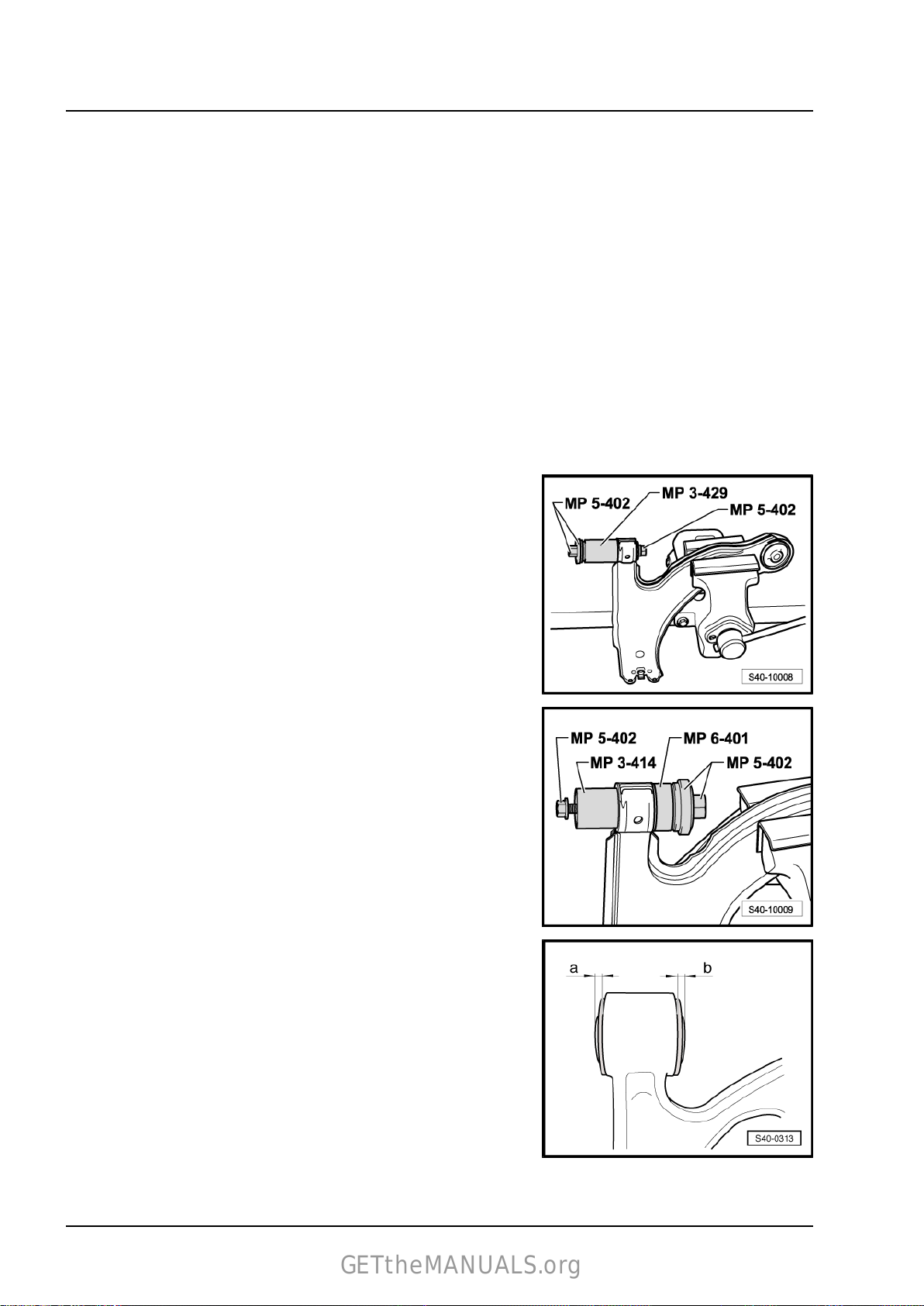
♦ Pressure plate - MP3-406 (VW 401)♦ Pressure plate - MP3-407 (VW 402)♦ Pipe - MP3-414 (VW 516)♦ Pipe - MP3-429 (2010)♦ Thrust washer - MP3-456 (VW 447 I)♦ Assembly tool - MP5-402 (3301)♦ Assembly tool - MP6-401 (3288)♦ Base - MP6-407 (40-103)♦ Pipe - MP6-408 (30-14)♦ Workshop press , e.g. -VAS 6654Press off front bearing for track control arm:
Press out rubber-metal bearing as shown.
Press in front bearing for track control arm:
– Insert front bearing in - pipe section - MP3-414 (VW 516)- .
In order not to damage the rubber-metal bearing when inserting
it, it must be positioned at an angle. During the press-in proce‐
dure, insert the rubber-metal bearing in the straightahead posi‐
tion.
– Apply assembly sliding oil - G 294 421 A1- to the outside of
the rubber-metal bearing.
– Press the rubber-metal bearing into the hole of the track con‐
trol arm.
The dimensions -a- and -b- must be identical after pressing in.
If the dimensions -a- and -b- are not identical:
– Slightly press out the bearing from the track control arm so that
the values -a- and -b- are identical.
22
Page 29

Fitting position of rear bearing for track control arm
GETtheMANUALS.org
– The marking -2- of the rubber-metal bearing must be posi‐
tioned to one axle with the marking -1- on the track control arm.
– The kidney-shaped recess -3- of the rubber-metal bearing
must always point towards the longitudinal vehicle axis.
Pressing out and in the rear bearing for the track control arm
Pay attention to the correct installation position of the rubber-
metal bearing during the press-in procedure (see Fig. S40-0389).
Rapid 2011 ➤
Axles, steering - Edition 12.2018
Note
♦
Use the assembly sliding oil (acid-free). E.g. 294 421 A1 to
press in the bearings.
♦
Do not use another grease!
2.7 Removing and installing the anti-roll bar
Special tools and workshop equipment required
♦ Engine and gearbox jack e.g. -V.A.G 1383/A- or -VAS6931♦ Fixing device - T10486/1♦ Fixing device - T10096Removing:
Vehicles with the exhaust system below the assembly carrier
– Remove pre-exhaust pipe ⇒ Engine; Rep. gr. 26 .
For vehicles with exhaust pipe inserted on the assembly carrier
– Remove spring washer for exhaust system to assembly carrier
⇒ Engine; Rep. gr. 26 .
Continued for all vehicles
23
Page 30

Rapid 2011 ➤
GETtheMANUALS.org
Axles, steering - Edition 12.2018
– Unscrew the screws -1- and -2- of the pendulum support.
– Unscrew the clamps of the anti-roll bar from the assembly car‐
rier -arrows-.
Note
♦
The anti-roll bar clamp is located behind the assembly carrier
and is not visible in the figure shown.
♦
The bottom screw of the right clamp can only be removed once
the assembly carrier has been lowered.
– Screw out the left and right nuts -1-.
– Pull out left and right coupling rod -3- from stabilizer -2-.
– Unscrew the screws -arrows- and tie up the power-steering
gear e.g with wire (attach), so that it maintains its position.
24
Page 31

– Insert wooden insert -1- in the adapter , e. g. -V.A.G 1359/2- .
GETtheMANUALS.org
– Support the assembly carrier with engine/gearbox jack with
adapter.
Note
♦
Note the following work steps and absolutely ensure that you
follow the sequence.
♦
The fixing bolts out from -T10096- and -T10486/1- must only
be tightened to maximum 20 Nm as otherwise the fixing bolt
thread becomes damaged.
– Unscrew left screw -1- for assembly carrier -4-, screw in fixing
bolt of -T10096- and tighten to 20 Nm.
– Unscrew right screw -1- for assembly carrier (not shown in
figure), screw in a fixing bolt from -T10096- and tighten to 20
Nm.
– Unscrew bolts -3- on both sides.
– Unscrew the left screw -2- and remove support -5-.
– Screw in fixing bolt -T10486/1- and tighten to 20 Nm.
– Unscrew the right screw -2- and remove support -5-.
– Screw in fixing bolt -T10486/1- and tighten to 20 Nm.
The alignment of the assembly carrier is completed once all 4
screws (Pos. -1- and -2- on both vehicle sides) are consecutively
replaced with the fixing bolts.
– Lower assembly carrier approx. 4 cm and through this slacken
from the fixing bolts.
Rapid 2011 ➤
Axles, steering - Edition 12.2018
Note
When lowering the assembly carrier make sure there is sufficient
clearance between the drive shafts and the stabilizer.
– Slowly lower the assembly carrier with engine/gearbox jack
and with adapter.
– Turn the anti-roll bar upwards and remove towards the rear.
Installing:
– Insert the anti-roll bar.
– Insert new screws for the anti-roll bar clamps and tighten
-arrows-.
– Raise the assembly carrier onto the fixing bolts and simulta‐
neously fit the power steering gear onto the assembly carrier.
Note
♦
Before inserting the screws for fixing the assembly carrier to
body, position the power-steering gear on the assembly carrier
and tighten with the new screws for the power-steering gear.
♦
Check correct positioning of gasket for power steering gear
onto the footwell opening of the vehicle.
25
Page 32

Rapid 2011 ➤
GETtheMANUALS.org
Axles, steering - Edition 12.2018
– Insert screws -arrows- and tighten by hand.
– Raise assembly carrier until the assembly carrier touches the
body.
– Tighten screws -arrows- of power steering gear/assembly car‐
rier to specified tighening torque and remove attachment (sus‐
pension) of the power steering gear.
Note
♦
Note the following work steps and absolutely ensure that you
follow the sequence.
♦
Unscrew the fixing bolts from -T10096- and -T10486/1- one at
a time. It should be subsequently replaced by a new bolt tight‐
ened to the recommended torque.
– Unscrew left fixing bolt -1- from -T10096- , screw in new screw
and tighten to the recommended tightening torque.
– Unscrew right fixing bolt -1- from -T10096- (not shown in fig‐
ure), screw in new screw and tighten to the recommended
tightening torque.
– Unscrew left fixing bolt -2- from -T10486/1- .
– Install left support.
– Screw in new bolts for the left support and tighten at the rear
by hand.
– Screw in new bolt for assembly carrier and left support and
tighten to the recommended tightening torque.
– Tighten the rear left support bolts to the recommended tight‐
ening torque.
– Unscrew right fixing bolt -2- from -T10486/1- (not shown in
figure).
– Install right support.
– Screw in new bolts for the right support and tighten at the rear
by hand.
– Screw in new bolt for assembly carrier and right support and
tighten to the recommended tightening torque.
– Tighten up the rear right support bolts to the recommended
tightening torque.
– Remove engine/gearbox jack with adapter .
– Mount pendulum support on the gearbox and tighten new
screws -1- and -2-.
Note
Position the screws -1- in the elongated holes of the pendulum
support in such a way that there is maximum distance between
the gearbox and the assembly carrier.
26
Page 33

– Insert left and right coupling rod -3- into the stabilizer -2-.
GETtheMANUALS.org
– Screw in the left and right nut -1- and tighten.
Vehicles with the exhaust system below the assembly carrier
– Install the pre-exhaust pipe ⇒ Engine; Rep. gr. 26 .
For vehicles with exhaust pipe inserted on the assembly carrier
– Install spring washer for exhaust system to assembly carrier
⇒ Engine; Rep. gr. 26 .
Continued for all vehicles
– Perform a test drive.
– Check the steering wheel position during the test drive.
Note
If after the test drive and with the front wheels pointing straight
ahead the steering wheel is off straight, perform an axle alignment
⇒ “2.2 Axle alignment”, page 129 .
Rapid 2011 ➤
Axles, steering - Edition 12.2018
27
Page 34

Rapid 2011 ➤
GETtheMANUALS.org
Axles, steering - Edition 12.2018
Tightening torques - summaries of components
Note
Replace bolts / nuts that are tightened at an angle of rotation, as well as replacement components after removal.
Power-steering gear to assembly carrier
♦ Use new screws!
Assembly carrier to body
♦ Use new screws!
Support to body
♦ Use new screws!
Hinged support to gearbox
♦ Use new screws!
Coupling rod to anti-roll bar 40 Nm
Clamp of anti-roll bar to assembly carrier
♦ Use new screws!
50 Nm + 180°.
70 Nm + 90°.
20 Nm + 90°.
30 Nm + 90°.
20 Nm + 90°.
28
Page 35

2.8 Removing and installing the rubber
GETtheMANUALS.org
bearing for the anti-roll bar
Removing
– Remove right drive shaft from the gearbox and tie up.
– Remove the screws -arrows- on both sides.
– Detach the spring clip from the rubber bearing.
– Detach the rubber bearing from the anti-roll bar.
Installing
– Fit the rubber bearing with the spring clip -1- onto the anti-roll
bar.
Rapid 2011 ➤
Axles, steering - Edition 12.2018
Note
♦
Ensure that the rubber bearing is positioned at the stop -2-.
♦
Depending on the version, the stop -2- may be located at the
outer or inner side of the rubber bearing.
– Install the screws -arrows- on both sides.
– Install right drive shaft on gearbox.
Tightening torques - summaries of components
Note
Replace bolts / nuts that are tightened at an angle of rotation, as
well as replacement components after removal.
Clamp of anti-roll bar to assembly carrier
♦ Use new screws!
Drive shaft to gearbox flange “M8”
♦ Use new screws!
♦ Use new washers!
20 Nm + 90°.
40 Nm
♦ First tighten crosswise to 10 Nm
29
Page 36

Rapid 2011 ➤
GETtheMANUALS.org
Axles, steering - Edition 12.2018
Drive shaft to gearbox flange “M10”
♦ Use new screws!
♦ Use new washers!
♦ First tighten crosswise to 10 Nm
2.9 Removing and installing assembly car‐
rier
Special tools and workshop equipment required
♦ Engine and gearbox jack e.g. -V.A.G 1383/A- or -VAS6931♦ Extractor - MP6-425 (3283)♦ Polycarmade grease - G 052 142 A2Removing:
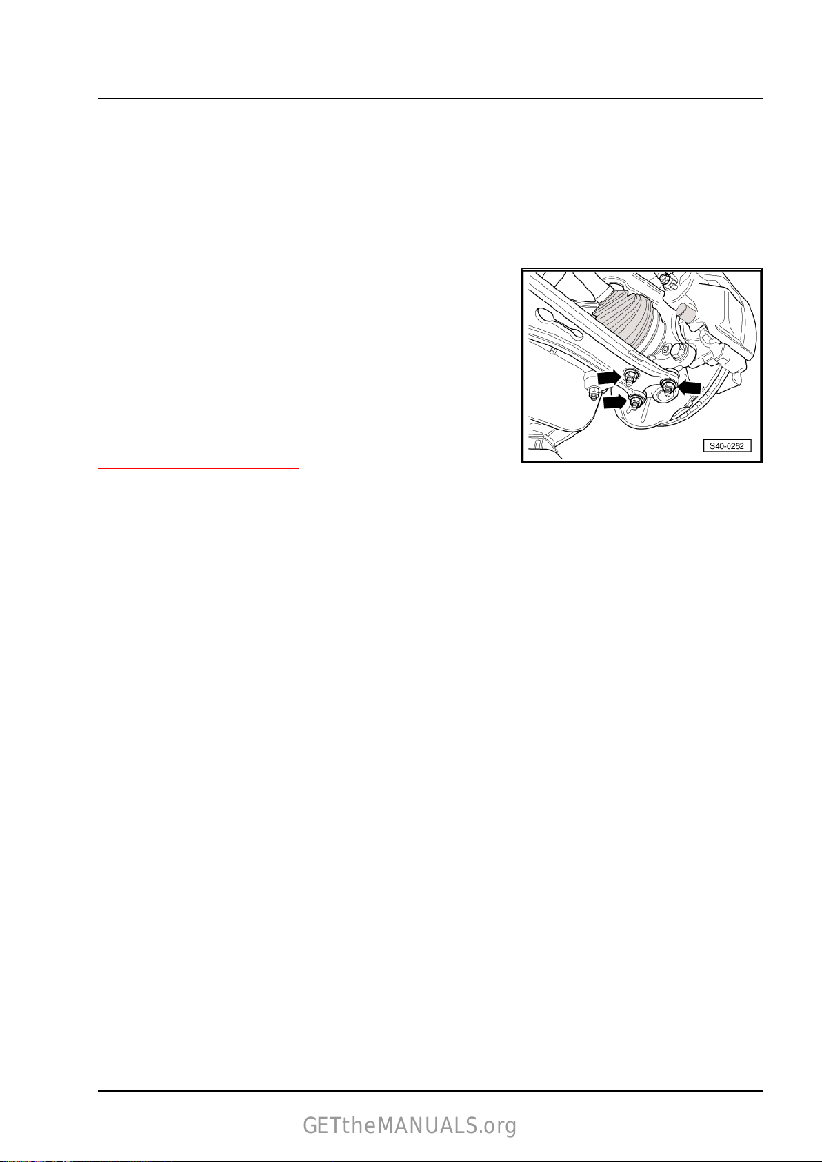
– Remove the nuts for the steering joint -arrows-.
– Pull the track control arm out of the steering joints.
70 Nm
– Screw out the left and right nuts -1-.
– Pull out left and right coupling rod -3- from stabilizer -2-.
– Swivel the anti-roll bar upwards.
– Unscrew the screws -arrows- and tie up the power-steering
gear e.g with wire (attach), so that it maintains its position.
– Release the assembly carrier and lower ⇒ “2.2 Lower the as‐
sembly carrier in the service position”, page 9 (do not remove
the universal joint of the steering column from the input shaft
of the power-steering gear).
– Remove assembly carrier.
Remove screws for anti-roll bar clamps and anti-roll bar, if nec‐
essary.
Installing:
Note
30
Page 37

Before inserting the fixing screws of the assembly carrier, position
GETtheMANUALS.org
the power-steering gear on the assembly carrier and tighten the
screws for the power-steering gear.
If necessary install anti-roll bar and tighten screws for anti-roll bar
clamps.
– Position the assembly carrier with engine/gearbox jack with
adapter.
– Raise the assembly carrier onto the fixing bolts and simulta‐
neously fit the power steering gear onto the assembly carrier.
– Insert screws -arrows- and tighten by hand.
– Raise assembly carrier until it touches the body.
Note
Check correct positioning of gasket for power steering gear onto
the footwell opening of the vehicle.
Rapid 2011 ➤
Axles, steering - Edition 12.2018
– Tighten screws -arrows- of power steering gear/assembly car‐
rier to specified tighening torque and remove attachment (sus‐
pension) of the power steering gear.
– Screw assembly carrier to body ⇒ “2.2 Lower the assembly
carrier in the service position”, page 9 .
– Insert left and right coupling rod -3- into the stabilizer -2-.
– Screw in the left and right nut -1- and tighten.
31
Page 38

Rapid 2011 ➤
GETtheMANUALS.org
Axles, steering - Edition 12.2018
– Insert the nuts for the steering joint -arrows-.
– Perform a test drive.
– Check the steering wheel position during the test drive.
Note
If after the test drive and with the front wheels pointing straight
ahead the steering wheel is off straight, perform an axle alignment
⇒ “2.2 Axle alignment”, page 129 .
32
Page 39

Tightening torques - summaries of components
GETtheMANUALS.org
Note
Replace bolts / nuts that are tightened at an angle of rotation, as well as replacement components after removal.
Rapid 2011 ➤
Axles, steering - Edition 12.2018
Power-steering gear to assembly carrier
♦ Use new screws!
Assembly carrier to body
♦ Use new screws!
Support to body
♦ Use new screws!
Coupling rod to anti-roll bar 40 Nm
Steering joint to track control arm
♦ Use new nuts!
Wheel bolts 120 Nm
50 Nm + 180°.
70 Nm + 90°.
20 Nm + 90°.
100 Nm
33
Page 40

Rapid 2011 ➤
GETtheMANUALS.org
Axles, steering - Edition 12.2018
3 Repairing front suspension strut
⇒ “3.1 Installation general view of the suspension strut”, page
34
⇒ “3.2 Removing and installing the suspension strut”, page
35
⇒ “3.3 Repairing suspension strut”, page 40
⇒ “3.4 Inspect shock absorber”, page 42
⇒ “3.5 Disposing of the shock absorber”, page 43
3.1 Installation general view of the suspension strut
Note
♦
Replace bolts / nuts that are tightened at an angle of rotation, as well as replacement components after
removal.
♦
The figure represents the wheel-bearing housing for disc brake FS-III. Different versions of the wheel-bear‐
ing housing do not influence the installation of the suspension strut.
1 - Wheel bearing housing
2 - Nut
❑ replace after each re‐
moval
❑ 60 Nm + 90°.
3 - Screw
❑ replace after each re‐
moval
4 - Shock absorber
❑ Removing and installing
⇒ “3.2 Removing and in‐
stalling the suspension
strut”, page 35
❑ can be replaced individ‐
ually
❑ Check ⇒ “3.4 Inspect
shock absorber”, page
42
❑ disposing of ⇒ “3.5 Dis‐
posing of the shock ab‐
sorber”, page 43
❑ Assignment ⇒ Elec‐
tronic Catalogue of
Original Parts
5 - Spring stop
6 - Boot
7 - Cap
8 - Flange nut, self-locking
♦ replace after each removal
❑ 60 Nm
9 - Spring cap
34
Page 41

Axles, steering - Edition 12.2018
GETtheMANUALS.org
10 - Suspension strut dome
11 - Flanged nut
♦ replace after each removal
❑ 60 Nm
12 - Suspension strut bearing
13 - Axial grooved ball bearing
14 - Spring cap
15 - Coil spring
❑ check colour coding
❑ The surface of the spring coil must not be damaged
❑ replace axle-wise
❑ the coil springs fitted to the axle must be of the same manufacturer
❑ Removing and installing ⇒ “3.3 Repairing suspension strut”, page 40
❑ Assignment ⇒ Electronic Catalogue of Original Parts
3.2 Removing and installing the suspension
strut
Rapid 2011 ➤
Special tools and workshop equipment required
♦ Engine and gearbox jack e.g. -V.A.G 1383/A- or -VAS6931♦ Spreader - 3424♦ Extractor - MP6-425 (3283)♦ Ball joint extractor - 3287A♦ Socket wrench insert WAF 21 - MP6-427 (3186)♦ Polycarbamide grease - G 052 142 A2Removing:
– Remove the outer joint of the drive shaft from the wheel-bear‐
ing housing ⇒ “5.3 Removing and installing outer joint of drive
shaft”, page 63 and tie up drive shaft to body.
– Screw steering joint to the track control arm. To do so use the
removed nuts.
– Unscrew the nut of the coupling rod -arrow B- from the sus‐
pension strut.
– Unhook ABS speed sensor cable from the suspension strut
(vehicles with ABS).
3. Repairing front suspension strut 35
Page 42

Rapid 2011 ➤
GETtheMANUALS.org
Axles, steering - Edition 12.2018
– Screw up nut -1- sufficiently so that the ball joint extractor is
supported on the nut.
– Use the ball joint extractor to remove the track rod with track
rod end -2- from the steering lever.
– Screw off the nut from the track rod end.
– Pull track rod end out of the steering arm.
– Tie up track rod.
– Position the engine/gearbox jack with adapter below the
wheel-bearing housing.
– Separate the screwed connection wheel-bearing housing/sus‐
pension strut -arrow-.
– Insert the clamping device - 3424- into the nut in the wheel-
bearing housing.
– Turn ratchet with spreader - 3424- by 90° and remove ratchet.
– Press the brake disc by hand towards the suspension strut.
Otherwise the shock absorber tube can cant in the opening of
the wheel bearing housing.
– Pull wheel-bearing housing downwards away from the shock-
absorber tube and lower with engine/gearbox jack with
adapter in such a way that the shock-absorber tube hangs
free.
– Secure thee wheel-bearing housing on the assembly carrier
(attach).
– Remove engine/gearbox jack with adapter.
– Unscrew the suspension strut from the body using the socket
wrench insert SW 21 - MP 6-427 (3186)- .
– Remove the suspension strut.
Installing:
– Insert suspension strut and screw into the suspension strut
dome.
– Tighten the nut to the specified tightening torque.
– Position the engine/gearbox jack with adapter below the
wheel-bearing housing.
– Insert suspension strut in the wheel-bearing housing.
– Loosen the suspension for the wheel-bearing housing from the
assembly carrier.
– Raise up the wheel-bearing housing using the engine/gearbox
jack with adapter to the point where the screw of the suspen‐
sion strut/wheel-bearing housing can be inserted.
36
Page 43

Caution
GETtheMANUALS.org
Never press on the steering joint with the engine/gearbox jack.
– Press the brake disc by hand towards the suspension strut and
make sure that the suspension strut tube does not clamp in
the opening for the wheel-bearing housing.
– Remove spreader - 3424- .
Rapid 2011 ➤
Axles, steering - Edition 12.2018
– Screw on the new nut and tighten up fully -arrow-.
– Install track rod with track rod end into the steering arm and
tighten.
– Hook the ABS speed sensor cable into the clips of the sus‐
pension strut (vehicles with ABS).
– Mount the coupling rod on the suspension strut and tighten
-arrow B-.
– Undo nuts -arrows- and remove lower arm from steering joint.
– Install the outer joint of the drive shaft into the wheel-bearing
housing ⇒ “5.3 Removing and installing outer joint of drive
shaft”, page 63 .
– Perform a test drive.
– Check the steering wheel position during the test drive.
Note
3. Repairing front suspension strut 37
Page 44

Rapid 2011 ➤
GETtheMANUALS.org
Axles, steering - Edition 12.2018
If after the test drive and with the front wheels pointing straight
ahead the steering wheel is off straight, perform an axle alignment
⇒ “2.2 Axle alignment”, page 129 .
38
Page 45

Tightening torques - summaries of components
GETtheMANUALS.org
Note
Replace bolts / nuts that are tightened at an angle of rotation, as well as replacement components after removal.
Rapid 2011 ➤
Axles, steering - Edition 12.2018
Suspension strut to suspension strut dome
♦ Use new screws!
Wheel-bearing housing to suspension strut
♦ Use new screws and nuts!
Track rod end/track rod to steering arm
♦ Use new nuts!
Coupling rod to suspension strut 40 Nm
Twelve-point nut for securing the drive shaft to wheel hub
♦ Use new nuts!
♦ Do not grease thread of the outer joint of the drive shaft.
Steering joint to track control arm
♦ Use new nuts!
Wheel bolts 120 Nm
60 Nm
60 Nm + 90°.
20 Nm + 90°.
50 Nm + 45°.
100 Nm
39
Page 46

Rapid 2011 ➤
GETtheMANUALS.org
Axles, steering - Edition 12.2018
3.3 Repairing suspension strut
Special tools and workshop equipment required
♦ Spring tensioner - V.A.G 1752/1♦ Spring holder , e.g. -V.A.G 1752/4♦ Socket wrench insert WAF 21 - MP6-427 (3186)-
Note
♦
Check correct seating of the helical spring in the spring ten‐
sioner , e.g. -V.A.G 1752/4- -arrow-.
♦
Do not use an impact screw driver when working with the
spring tensioner.
Removing the coil spring:
– Removing the suspension strut ⇒ “3.2 Removing and installing
the suspension strut”, page 35 .
– Preload the helical spring with the spring tensioner until the
spring cap ⇒ Item 14 (page 35) is relieved.
– Unscrew the nut from the piston rod using the socket wrench
insert SW 21 - MP6-427 (3186)- and counterhold with a
hexagon wrench -2-.
1 - Ratchet; when installing torque spanner
– Remove the individual parts of the suspension strut and the
coil spring with the spring tensioner.
Installing the coil spring:
– Insert the preloaded coil spring with the spring tensioner onto
the bottom coil spring bearing.
The thread end of the helical spring must lie against the
stop -arrow-.
Further installation occurs in reverse order.
– Assembly and summary of components of the suspension
strut ⇒ “3.1 Installation general view of the suspension strut”,
page 34 .
40
Page 47

Tightening torques - summaries of components
GETtheMANUALS.org
Note
Replace bolts / nuts that are tightened at an angle of rotation, as well as replacement components after removal.
Nut of suspension strut bearing on piston rod 60 Nm
Rapid 2011 ➤
Axles, steering - Edition 12.2018
41
Page 48

Rapid 2011 ➤
GETtheMANUALS.org
Axles, steering - Edition 12.2018
3.4 Inspect shock absorber
Leaks on the shock absorber
Minor oil leakage (sweating) on the piston rod seal does not entail
the replacement of the shock absorber.
If an oil leak is visible (but blunt, dull, possibly dried by dust) and
does not propagate any further than from the top shock-absorber
screw plug (piston rod seal) to the bottom spring cap -arrow-, the
shock absorber is deemed to be O.K.
Note
A slight oil leak is beneficial as the gasket is lubricated and this
increases the life time. This applies for shock absorbers on the
front as well as the rear axle.
Noises on the shock absorber
There is reason to believe that in the event of noise complaints
the shock absorbers are all too often considered as the source.
Possible causes of noise may be e.g.:
♦ defective shock absorber
♦ suspension strut/body attachment is loose
♦ defective axial grooved ball bearing
♦ poor operation of the suspension strut
♦ defective outer joint
♦ defective wheel bearing
♦ cracked welding points on body
♦ parts loosened or overtensioned when installed (exhaust sys‐
tem, attachments, flaps, etc.)
Note
In the event of complaints about noises interpreted as knocking
or cracking noises, always first perform a test drive with the cus‐
tomer to determine where, when and how these noises occur
(preferably on a bumpy dry road).
Inspecting the removed shock absorber without gas pressure
Defective shock absorbers become noticeable while driving be‐
cause of the knocking noises caused by wheel hopping, more
specifically on poor road surfaces and they must be replaced. The
failure is mainly caused by the loss of oil. The shock absorber
then compresses and/or expands in jolts. It exhibits “idle”, before
it begins to operate.
Note
The shock absorbers are maintenance-free. It is not possible to
top up the shock absorber oil.
Inspecting the removed shock absorber with gas pressure
42
Page 49

Damaged shock absorbers with gas pressure become noticeable
GETtheMANUALS.org
because of a laud banging sound, caused by wheel hopping, and
also because a strong oil leak occurs.
Manual testing, as described below, can determine if the
shock absorber is damaged or not:
– Compress the shock absorber by hand.
The piston rod must move evenly over the entire stroke without
jolting.
– Release the piston rod. On sufficiently pressurized shock ab‐
sorbers it will automatically return to its original position.
If this is not the case, the shock absorber need not necessarily
be replaced, as it will still operate as a conventional shock ab‐
sorber (see instructions below).
Note
♦
The absorbing function is still fully present without sufficient
gas pressure as long as the oil leakage is not too large. How‐
ever, the noise level may increase. On older vehicles it is
possible to continue using an operational yet pressureless
shock absorber without problem.
♦
Adequate gas pressure in the shock absorber improves the
noise behaviour and function when driving over poor road sur‐
faces.
Rapid 2011 ➤
Axles, steering - Edition 12.2018
3.5 Disposing of the shock absorber
Special tools and workshop equipment required
♦ Drill ∅ 3 mm (commercially available)
♦ Drill ∅ 6 mm (commercially available)
♦ Safety goggles (commercially available)
♦ Oil catch container (commercially available)
Degas front gas pressure shock absorber
– Clamp gas-filled shock absorber vertically with the piston rod
pointing downwards in a vice.
WARNING
Wear safety goggles during the drilling procedure.
– Drill a hole ∅ 3 mm -A- through the outer pipe of the shock
absorber.
Note
Gas will escape during drilling.
– Drill further until the inner pipe has also been drilled through
(approx. 25 mm deep).
– Drill a second hole ∅ 6 mm -B- through the outer and inner
shock absorber pipes.
43
Page 50

Rapid 2011 ➤
GETtheMANUALS.org
Axles, steering - Edition 12.2018
– Hold the shock absorber over an oil catching pan. Move the
piston rod several times up and down over its entire stroke until
no more oil escapes.
Degas rear gas pressure shock absorber
– Clamp the gas-filled shock absorber vertically in the vice.
WARNING
Wear safety goggles during the drilling procedure.
– Drill a hole ∅ 3 mm -A- through the outer pipe of the shock
absorber.
Note
Gas will escape during drilling.
– Drill further until the inner pipe has also been drilled through
(approx. 25 mm deep).
– Drill a second hole ∅ 6 mm -B- through the outer and inner
shock absorber pipes.
– Hold the shock absorber over an oil catching pan. Move the
piston rod several times up and down over its entire stroke until
no more oil escapes.
44
Page 51

Rapid 2011 ➤
GETtheMANUALS.org
Axles, steering - Edition 12.2018
4 Repairing wheel bearing
⇒ “4.1 Summary of components of the wheel bearing, suspension
strut, drive shaft and brake C54”, page 45
⇒ “4.2 Removing and installing wheel bearing housing”, page
48
⇒ “4.3 Removing and installing the wheel hub with wheel bearing
with the wheel-bearing housing fitted”, page 52
4.1 Summary of components of the wheel bearing, suspension strut, drive shaft and brake C54
Note
♦
Replace bolts / nuts that are tightened at an angle of rotation, as well as replacement components after
removal.
♦
Welding and straightening work is not allowed on the bearing and wheel control components of the front
wheel suspension.
♦
Always replace the self-locking screws and nuts.
♦
Always replace corroded self-locking nuts and screws.
4. Repairing wheel bearing 45
Page 52

Rapid 2011 ➤
GETtheMANUALS.org
Axles, steering - Edition 12.2018
1 - Suspension strut
❑ Removing and installing
⇒ “3.2 Removing and in‐
stalling the suspension
strut”, page 35
❑ repairing ⇒ “3.3 Repair‐
ing suspension strut”,
page 40
❑ Assignment ⇒ Elec‐
tronic Catalogue of
Original Parts
2 - Drive shaft with inner CV
joint
❑ Removing and installing
⇒ “5.4 Removing and in‐
stalling drive shaft with
CV joint”, page 66
❑ Check ⇒ “5.7 Inspecting
the CV joints”, page
72
❑ repairing ⇒ “5.6 Repair‐
ing drive shaft with CV
joint”, page 69
❑ Assignment ⇒ Elec‐
tronic Catalogue of
Original Parts
3 - Supporting plate
❑ Assignment ⇒ Elec‐
tronic Catalogue of
Original Parts
4 - Fillister head screw with in‐
ternal serrations
❑ replace after each re‐
moval
❑ first pre-tighten all
screws crosswise up to 10 Nm and subsequently tighten crosswise to final tightening torque:
Screw M 8 = 40 Nm
Screw M 10 = 70 Nm
❑ Assignment ⇒ Electronic Catalogue of Original Parts
5 - Drive shaft with inner tripod joint
❑ Removing and installing ⇒ “6.2 Removing and installing inner drive shaft with tripod joint”, page 78
❑ repairing ⇒ “6.3 Repairing drive shaft with inner tripod joint”, page 82
❑ Assignment ⇒ Electronic Catalogue of Original Parts
6 - Circlip
❑ replace after each removal
7 - Brake disc, internally ventilated
8 - Wheel bolt
❑ Assignment ⇒ Electronic Catalogue of Original Parts
❑ 120 Nm
9 - Twelve-point nut
❑ replace after each removal
❑ Do not grease thread of the outer joint of the drive shaft.
❑ Removing and installing ⇒ “5.2 Removing and installing fixing nut of drive shaft”, page 61
46
Page 53

Rapid 2011 ➤
GETtheMANUALS.org
Axles, steering - Edition 12.2018
❑ Assignment ⇒ Electronic Catalogue of Original Parts
❑ 50 Nm + 45°.
10 - Screw
❑ 4 Nm
11 - Brake pad
❑ removing and installing ⇒ Brake systems; Rep. gr. 46
12 - Pad retaining plate
❑ always replace when changing the brake pads
❑ contained in the repair kit for brake pads
13 - Brake carrier with guide bolts and boots
14 - Brake caliper
❑ Assignment ⇒ Electronic Catalogue of Original Parts
❑ do not release brake hose when working on the front wheel suspension
❑ tie up with wire or anything similar
❑ repairing ⇒ Brake systems; Rep. gr. 46
15 - Screw
❑ replace after each removal
❑ 30 Nm
16 - Track rod and track-rod ends
❑ Removing and installing ⇒ “5.4 Removing and installing track rods”, page 162
17 - Wheel hub with wheel bearing
❑ for vehicles with ABS the sensor ring is built into the wheel hub
❑ The wheel hub and the wheel bearing are a single unit; it does not need servicing and is free of play; it
is not possible to undertake any kind of adjustment or repair work on it.
❑ The sensor ring for ABS cannot be replaced individually
❑ replace after each disassembly, wheel hub with wheel bearing is destroyed during removal
❑ Removing and installing ⇒ “4.3 Removing and installing the wheel hub with wheel bearing with the wheel-
bearing housing fitted”, page 52
❑ Assignment ⇒ Electronic Catalogue of Original Parts
18 - Screw
❑ 10 Nm
19 - Protection plate
20 - Nut
❑ replace after each removal
❑ 20 Nm + 90°.
21 - Screw
❑ clean ribbing on underside each time removed
❑ 125 Nm
22 - Nut
❑ replace after each removal
❑ 60 Nm + 90°.
23 - Wheel bearing housing
❑ Removing and installing ⇒ “4.2 Removing and installing wheel bearing housing”, page 48
❑ Assignment ⇒ Electronic Catalogue of Original Parts
24 - Screw
❑ replace after each removal
❑ the tip of bolt must point in the direction of travel
4. Repairing wheel bearing 47
Page 54

Rapid 2011 ➤
GETtheMANUALS.org
Axles, steering - Edition 12.2018
25 - ABS wheel speed sensor
❑ Assignment ⇒ Electronic Catalogue of Original Parts
26 - Hexagon socket head bolt
❑ for ABS speed sensor
❑ 8 Nm
27 - Nut
❑ Assignment ⇒ Electronic Catalogue of Original Parts
❑ 40 Nm
28 - Coupling rod
❑ Assignment ⇒ Electronic Catalogue of Original Parts
4.2 Removing and installing wheel bearing housing
Special tools and workshop equipment required
♦ Engine and gearbox jack e.g. -V.A.G 1383/A- or -VAS6931♦ Spreader - 3424♦ Extractor - MP6-425 (3283)♦ Ball joint extractor - 3287A♦ Polycarmade grease - G 052 142 A2Removing:
– Unscrew twelve-point nut for securing the drive shaft ⇒
“5.2 Removing and installing fixing nut of drive shaft”, page
61 .
– Remove wheel.
– Turn the nut -1-.
– Pull out coupling rod -3- from the anti-roll bar -2-.
– Remove ABS speed sensor (vehicles with ABS) ⇒ Brake sys‐
tems; Rep. gr. 45 .
– Unscrew bolts -1-.
– Remove brake caliper or brake carrier with brake caliper and
secure with wire in such a way that the weight of the brake
caliper does not burden or damage the brake line.
– Remove the outer joint of the drive shaft from the wheel-bear‐
ing housing ⇒ “5.3 Removing and installing outer joint of drive
shaft”, page 63 and tie up drive shaft to body.
48
Page 55

– Screw up nut -1- sufficiently so that the ball joint extractor is
GETtheMANUALS.org
supported on the nut.
– Use puller to remove track rod/track rod end -2- from the steer‐
ing arm.
– Screw off the nut from the track rod end.
– Pull track rod end out of the steering arm.
– Tie up track rod.
– Remove steering joint from wheel-bearing housing ⇒ “2.4 Re‐
moving and installing the suspension link”, page 15 .
– Position the engine/gearbox jack with adapter below the
wheel-bearing housing.
Rapid 2011 ➤
Axles, steering - Edition 12.2018
– Separate the screwed connection wheel-bearing housing/sus‐
pension strut -arrow-.
– Insert the clamping device - 3424- into the nut in the wheel-
bearing housing.
– Turn the spreader - 3424- with ratchet 90° and remove ratchet.
– Press the brake disc by hand towards the suspension strut.
Otherwise the shock absorber tube can cant in the opening of
the wheel bearing housing.
– Remove the wheel-bearing housing from the shock-absorber
tube and lower with engine/gearbox jack with adapter.
Installing:
– Raise up the wheel-bearing housing using the engine/gearbox
jack with adapter and position on the shock absorber pipe.
Note
Never press on the steering joint with the engine/gearbox jack
with adapter.
– Insert the new suspension strut/wheel-bearing housing screw.
4. Repairing wheel bearing 49
Page 56

Rapid 2011 ➤
GETtheMANUALS.org
Axles, steering - Edition 12.2018
– With one's hand on the brake disc press in the direction of the
suspension strut and make sure that the shock-absorber tube
in the bore hole of the wheel-bearing housing does not be‐
come tilted.
– Remove spreader - 3424- .
– Tighten the screwed connection wheel-bearing housing/sus‐
pension strut with a new nut -arrow-.
– Install track rod with track rod end into the steering arm and
tighten.
– Install brake caliper in reverse order to removal depending on
brake caliper type and tighten.
– Install ABS speed sensor (vehicles with ABS) ⇒ Brake sys‐
tems; Rep. gr. 45 .
– Insert the outer joint of the drive shaft into the wheel-bearing
housing ⇒ “5.3 Removing and installing outer joint of drive
shaft”, page 63 .
– Insert coupling rod -3- into the stabilizer -2-.
– Tighten the nut -1-.
– Install steering joint ⇒ “2.4 Removing and installing the sus‐
pension link”, page 15 .
– Installing and tightening the wheel.
– Screw in twelve-point nut for securing the drive shaft ⇒
“5.2 Removing and installing fixing nut of drive shaft”, page
61 .
Note
It is necessary to perform an axle alignment in the event of: ⇒
“2.2 Axle alignment”, page 129 .
– Perform a test drive.
– Check the steering wheel position during the test drive.
Note
If after the test drive and with the front wheels pointing straight
ahead the steering wheel is off straight, perform an axle alignment
⇒ “2.2 Axle alignment”, page 129 .
50
Page 57

Tightening torques - summaries of components
GETtheMANUALS.org
Note
Replace bolts / nuts that are tightened at an angle of rotation, as well as replacement components after removal.
Rapid 2011 ➤
Axles, steering - Edition 12.2018
Wheel-bearing housing to suspension strut
♦ Use new screws and nuts!
Twelve-point nut for securing the drive shaft to wheel hub
♦ Use new nuts!
♦ Do not grease thread of the outer joint of the drive shaft.
Track rod end to steering arm
♦ Use new nuts!
Steering joint to track control arm
♦ Use new nuts!
Brake carrier with brake caliper to wheel bearing housing 125 Nm
ABS speed sensor to wheel-bearing housing 8 Nm
Coupling rod to anti-roll bar 40 Nm
Wheel bolts 120 Nm
60 Nm + 90°.
50 Nm + 45°.
20 Nm + 90°.
100 Nm
51
Page 58

Rapid 2011 ➤
GETtheMANUALS.org
Axles, steering - Edition 12.2018
4.3 Removing and installing the wheel hub
with wheel bearing with the wheel-bear‐
ing housing fitted
Special tools and workshop equipment required
♦ Assembly tool - MP6-414 (3253)♦ Assembly tool - T10064♦ Assembly tool - T10178♦ Ball joint extractor - 3287A♦ Socket insert SW 36 - T10125♦ Engine and gearbox jack e.g. -V.A.G 1383/A- or -VAS6931♦ Molykote grease - G 052 723 A2Removing the wheel hub with wheel bearing:
– Unscrew twelve-point nut for securing the drive shaft ⇒
“5.2 Removing and installing fixing nut of drive shaft”, page
61 .
Note
♦
If the fixing nut of the drive shaft is loose on the wheel side,
the wheel bearings must not be loaded.
♦
If the wheel bearings are loaded through the vehicle's own
weight, the wheel bearing will be initially damaged. This short‐
ens the life of the wheel bearing.
♦
It is not permissible to turn cardan shaft screw more than 90°
anti-clockwise if vehicle is standing on its wheels.
♦
The vehicles without drive shaft must not be moved, otherwise
the wheel bearing will be damaged If you still want to move the
vehicle, please note the following: install the outer joint instead
of the PTO shaft. Tighten outer CV joint to 25 Nm.
– Remove wheel.
– Unscrew nut -1- and remove coupling rod -3- from anti-roll bar
-1-.
– Pull out coupling rod -3- from the anti-roll bar -2-.
– Disconnect the brake line and electrical lines from the wheel
bearing housing and expose them.
52
Page 59

– Remove ABS speed sensor (vehicles with ABS) ⇒ Brake sys‐
GETtheMANUALS.org
tems; Rep. gr. 45 .
– Unscrew bolts -1- from the brake caliper and remove.
– Remove brake carrier with brake caliper and secure with wire
in such a way that the weight of the brake caliper does not pull
on or damage the brake hose.
– Screw out nut for track-rod ends -1- sufficiently so that the ball
joint extractor is supported on the nut.
Note
♦
To protect the thread, screw the nut a couple of thread turns
onto the track-rod end.
♦
While pressing out the tie rod end, be aware of the injury risk:
the ball joint puller may fall out when the tie rod end stud is
loosened.
Rapid 2011 ➤
Axles, steering - Edition 12.2018
– Use puller to remove track rod/track rod end -2- from the steer‐
ing arm.
– Screw off the nut from the track rod end.
– Pull track rod end out of the steering arm.
– Tie up track rod.
– Remove the outer joint of the drive shaft from the wheel-bear‐
ing housing ⇒ “5.3 Removing and installing outer joint of drive
shaft”, page 63 and tie up drive shaft to body.
– Screw steering joint to the track control arm. To do so use the
removed nuts.
– Unscrew the securing screw of the brake disc and remove
brake disc.
– Remove splash plate for brakes.
Note
♦
Mount the assembly device - MP6-414 (3253)- at right angles
to the centre axle of the wheel hub with wheel bearing. Do not
tilt the wheel hub with wheel bearing when removing and in‐
stalling.
♦
Place engine and transmission jack , e.g. -V.A.G 1383/A- or -
VAS6931- underneath (risk of injury from falling parts when
removing the wheel hub with the wheel bearing).
♦
The wheel hub is pulled out with the wheel bearing as follows,
whereby the wheel bearing housings differ visually depending
on the brake variant.
Push out wheel hub with wheel bearing
Note
53
Page 60

Rapid 2011 ➤
GETtheMANUALS.org
Axles, steering - Edition 12.2018
To avoid injury from falling parts when pulling the wheel hub with
the wheel bearing out of the wheel bearing housing, place the
motor and gear jack underneath.
– Assemble the device as illustrated.
1 - Clamp - MP6-414/2 (3253/2)2 - Pipe - MP6-414/1 (3253/1)3 - Pressure element - MP6-414/6 (3253/6)4 - Screw - MP6-414/10 (3253/3)5 - Assembly tool - T101786 - Thrust bearing -MP6-414 (3253)7 - Pressure element - MP6-414/5 (3253/5)- (used with small
diameter in thrust bearing position 6)
8 - Nut - MP6-414/10 (3253/3)– Pull the wheel hub with wheel bearing out of the wheel bearing
housing (device must be held in place).
Installing the wheel hub with wheel bearing:
Note
♦
Clean the bore of the wheel bearing housing (wheel bearing
housings differ visually depending on the brake variant).
♦
Clean the bore in the wheel bearing housing.
– Coat the entire surface of the hole with Molykote grease - G
052 723 A2- .
– Screw in wheel bolts -2- in the hub as shown.
– Screw grippers - T10064/6A- together with wheel bolts -2- and
wheel hub.
1 - Wheel hub with wheel bearing
2 - Wheel bolts
3 - Grippers - T10064/6AThe wheel bolts -2- must not protrude from the rear of the grip‐
pers.
Pressing in wheel hub with wheel bearing
Note
54
Page 61

Do not tilt the wheel hub with wheel bearing while inserting.
GETtheMANUALS.org
– Pull the wheel hub with wheel bearing into the wheel-bearing
housing.
1 - -MP6-414/5 (3253/5)2 - -T10064/13 - -T10064/6A4 - -MP6-414/10 (3253/3)5 - -T10064/4– Pull in the wheel hub with wheel bearing until the circlip is
heard to click into position.
– Unscrew screws -3- and remove grippers -1- from the wheel
hub with wheel bearing -2-.
Rapid 2011 ➤
Axles, steering - Edition 12.2018
– Release fixing nuts -arrows-.
– Unhook steering joint out of the suspension link.
– Insert the outer joint of the drive shaft into the wheel-bearing
housing ⇒ “5.3 Removing and installing outer joint of drive
shaft”, page 63 .
– Screw the steering joint to the track control arm with new nuts
-arrows-.
– Install splash plate for brakes.
– Install brake disc and secure with screw.
– Install track rod with track rod end into the steering arm and
tighten.
– Install brake caliper in reverse order to removal depending on
brake caliper type and tighten.
– Connect the plug connection for the brake pad wear indicator
(where the vehicle is fitted with this).
– Install ABS speed sensor (vehicles with ABS) ⇒ Brake sys‐
tems; Rep. gr. 45 .
– Secure brake line and electric lines to wheel bearing housing.
55
Page 62

Rapid 2011 ➤
GETtheMANUALS.org
Axles, steering - Edition 12.2018
– Insert coupling rod -3- into anti-roll bar -2- and tighten nut -1-
to the specified tightening torque.
– Install retaining nut of drive shaft ⇒ “5.2 Removing and in‐
stalling fixing nut of drive shaft”, page 61 .
– Attach the wheel.
– Tighten retaining nut of drive shaft ⇒ “5.2 Removing and in‐
stalling fixing nut of drive shaft”, page 61 .
– Perform a test drive.
Note
If after the test drive and with the front wheels pointing straight
ahead the steering wheel is off straight, perform an axle alignment
⇒ “2.2 Axle alignment”, page 129 .
56
Page 63

Rapid 2011 ➤
GETtheMANUALS.org
Axles, steering - Edition 12.2018
Tightening torques - summaries of components
Note
Replace bolts / nuts that are tightened at an angle of rotation, as well as replacement components after removal.
Cover plate to wheel-bearing housing 10 Nm
Phillips head screw of brake disc to wheel hub with wheel bearing 4 Nm
Twelve-point nut for securing the drive shaft to wheel hub
♦ Use new nuts!
♦ Do not grease thread of the outer joint of the drive shaft.
50 Nm + 45°.
Track rod/track rod end to steering arm
♦ Use new nuts!
Steering joint to track control arm
♦ Use new nuts!
Brake carrier with brake caliper to wheel bearing housing 125 Nm
ABS speed sensor to wheel-bearing housing 8 Nm
Coupling rod to anti-roll bar 40 Nm
Wheel bolts 120 Nm
20 Nm + 90°.
100 Nm
57
Page 64

Rapid 2011 ➤
GETtheMANUALS.org
Axles, steering - Edition 12.2018
5 Drive shafts with inner CV joint
⇒ “5.1 Summary of components of drive shaft with inner CV joint”,
page 58
⇒ “5.2 Removing and installing fixing nut of drive shaft”, page
61
⇒ “5.3 Removing and installing outer joint of drive shaft”, page
63
⇒ “5.4 Removing and installing drive shaft with CV joint”, page
66
⇒ “5.6 Repairing drive shaft with CV joint”, page 69
⇒ “5.7 Inspecting the CV joints”, page 72
5.1 Summary of components of drive shaft with inner CV joint
Note
♦
Replace bolts / nuts that are tightened at an angle of rotation, as well as replacement components after
removal.
♦
Assignment of the drive shafts ⇒ Electronic Catalogue of Original Parts .
♦
Grease the joint if necessary, when replacing the joint boot.
♦
Spread the grease mass evenly in the joint.
58
Page 65

Rapid 2011 ➤
GETtheMANUALS.org
Axles, steering - Edition 12.2018
1 - Right joint boot (tubular
shaft)
❑ Assignment ⇒ Elec‐
tronic Catalogue of
Original Parts
2 - Screw
❑ replace after each re‐
moval
❑ first of all pre-tighten all
screws crosswise up to
10 Nm and subsequent‐
ly tighten crosswise to fi‐
nal torque:
Screw M 8 = 40 Nm
Screw M 10 = 70 Nm
❑ Assignment ⇒ Elec‐
tronic Catalogue of
Original Parts
3 - Supporting plate
❑ Assignment ⇒ Elec‐
tronic Catalogue of
Original Parts
4 - Clamp
❑ Replacing
❑ tensioning ⇒ “5.6 Re‐
pairing drive shaft with
CV joint”, page 69
5 - Joint boot for inner joint
❑ inspect for tears and
chafing points
❑ drive off from joint with a
drift
❑ before installation coat
the inside of the cap with sealant - D 454 300 A2-
❑ Assignment ⇒ Electronic Catalogue of Original Parts
6 - Disc spring
❑ Fitting position ⇒ page 71
7 - Inner joint
❑ must be replaced completely
❑ remove ⇒ page 71
❑ inserting ⇒ page 71
❑ grease ⇒ page 60
❑ Check ⇒ “5.7.2 Disassembling, inspecting and assembling the inner CV joint”, page 73
❑ Assignment ⇒ Electronic Catalogue of Original Parts
8 - Seal
❑ The adhesive surface must be free of grease and oil
❑ replace after each removal
❑ Pull off protective foil and stick in joint
❑ Assignment ⇒ Electronic Catalogue of Original Parts
9 - Circlip
❑ Replacing
5. Drive shafts with inner CV joint 59
Page 66

Rapid 2011 ➤
GETtheMANUALS.org
Axles, steering - Edition 12.2018
❑ use circlip pliers , e.g. -VW 161 A- , for removing and installing
❑ Assignment ⇒ Electronic Catalogue of Original Parts
10 - Left drive shaft (solid shaft)
❑ Assignment ⇒ Electronic Catalogue of Original Parts
11 - Clamp
❑ Replacing
❑ tensioning ⇒ “5.6 Repairing drive shaft with CV joint”, page 69
12 - Boot
❑ inspect for tears and chafing points
❑ Assignment ⇒ Electronic Catalogue of Original Parts
13 - Clamp
❑ Replacing
❑ tension with tensioning pliers , e. g. -V.A.G 1682 A- ⇒ “5.6 Repairing drive shaft with CV joint”, page
69
14 - Disc spring
❑ Fitting position ⇒ “5.6 Repairing drive shaft with CV joint”, page 69
15 - Thrust ring
❑ Fitting position ⇒ “5.6 Repairing drive shaft with CV joint”, page 69
16 - Circlip
❑ Replacing
❑ insert in the shaft groove
17 - Outer CV joint
❑ must be replaced completely
❑ Remove constant velocity joint ⇒ page 70
❑ before installing grease the serration with polycarbamide grease - G 052 142 A2❑ carefully drive onto the shaft with a plastic hammer until the compressed circlip expands
❑ grease ⇒ page 60
❑ Check ⇒ “5.7.1 Disassembling, inspecting and assembling the outer CV joint”, page 72
❑ Assignment ⇒ Electronic Catalogue of Original Parts
18 - Thrower ring
❑ Assignment ⇒ Electronic Catalogue of Original Parts
19 - Twelve-point nut
❑ Removing and installing fixing nut of drive shaft ⇒ “5.2 Removing and installing fixing nut of drive shaft”,
page 61
❑ replace after each removal
❑ 50 Nm + 45°.
Grease quality and grease quantity
Note
♦
The outer joints of the drive shaft are filled with grease for op‐
erating at normal temperatures, e.g. -N 052 738 00- .
♦
Only use the appropriate high-temperature grease from the
relevant repair kit for the grease filling of the inner CV joint ⇒
Electronic Catalogue of Original Parts .
60
Page 67

Rapid 2011 ➤
GETtheMANUALS.org
Axles, steering - Edition 12.2018
∅ Joint
(mm)
Outer joint
∅ 103
Inner joint
∅ 100
Total grease
quantity
(g)
±10
125
±10
110
Grease quantity distribution
Outer joint (g) Inner joint and
joint boot (g)
40 Residual amount
80 Residual amount
5.2 Removing and installing fixing nut of drive shaft
Note
♦
If the fixing nut of the drive shaft is loose on the wheel side,
the wheel bearings must not be loaded.
♦
If the wheel bearings are loaded through the vehicle's own
weight, the wheel bearing will be initially damaged. This short‐
ens the life of the wheel bearing.
♦
The vehicles without drive shaft must not be moved, otherwise
the wheel bearing will be damaged If you still want to move the
vehicle, please note the following: install the outer joint instead
of the PTO shaft. Tighten outer CV joint to 25 Nm.
Remove nut:
– Remove wheel trim cap, for light-alloy wheels (depending on
version) remove the cap on the removed wheel.
– Slacken the nut -arrow- by max. 90° on the vehicle while it is
standing on its wheels, otherwise the wheel bearing may be
damaged.
If the wheel is removed, also slacken the wheel bolts.
– Raise the vehicle until the wheels are fully off the ground.
– Depress brake pedal (assistance of second mechanic re‐
quired).
– Release nut -arrow- and release brake pedal.
Install nut:
– Install new nut.
Note
The wheels should not touch the ground when tightening the fix‐
ing nut of the drive shaft, otherwise the wheel bearings will be
damaged.
– Depress brake pedal (assistance of second mechanic re‐
quired).
– Tighten the new nut to 50 Nm and release the brake pedal.
– Place vehicle onto its wheels.
– Tighten nut and torque a further 45°.
5. Drive shafts with inner CV joint 61
Page 68

Rapid 2011 ➤
GETtheMANUALS.org
Axles, steering - Edition 12.2018
Tightening torques - summaries of components
Note
Replace bolts / nuts that are tightened at an angle of rotation, as well as replacement components after removal.
Twelve-point nut for securing the drive shaft to wheel hub
♦ Use new nut!
♦ Do not grease thread of the outer joint of the drive shaft.
Wheel bolt 120 Nm
50 Nm + 45°.
62
Page 69

5.3 Removing and installing outer joint of
GETtheMANUALS.org
drive shaft
Special tools and workshop equipment required
♦ Polycarbamide grease - G 052 142 A2Removing:
– Unscrew twelve-point nut for securing the drive shaft ⇒
“5.2 Removing and installing fixing nut of drive shaft”, page
61 .
– Remove front wheel.
– Unscrew the nuts -arrows-.
– Remove track control arm from steering joint.
– Swivel out the wheel-bearing housing with the suspension
strut and take the drive shaft out of the wheel-bearing housing.
Tie up drive shaft.
Note
♦
The drive shaft must not hang down! The inner joint can be
damaged by excessive offset.
♦
If the cardan shaft cannot be removed from the wheel hub, it
can be pressed out using the extractor ⇒ “5.5 Push the cardan
shaft out of the wheel hub.”, page 69 .
Rapid 2011 ➤
Axles, steering - Edition 12.2018
Installing:
Note
Remove possible corrosion and grease residue from the thread
and from the serration of the outer joint as well as from the ser‐
ration of the wheel-bearing housing.
– Grease the serration on the propeller shaft with polycarbamide
grease - G 052 142 A2- .
Do not grease thread on the outer joint of the drive shaft.
– Grease the serration in the wheel-bearing housing with poly‐
carbamide grease - G 052 142 A2- .
– Slide the outer joint into the serration of the wheel-bearing
housing.
– Secure the outer joint of the drive shaft with a new twelve-point
nut.
Note
♦
Use new nuts to screw the track control arm/steering joint.
♦
Make sure the steering joint boot is neither damaged nor twist‐
ed.
63
Page 70

Rapid 2011 ➤
GETtheMANUALS.org
Axles, steering - Edition 12.2018
– Screw steering joint to the track control arm -arrows-.
– Tighten new twelve-point nut for securing the drive shaft ⇒
“5.2 Removing and installing fixing nut of drive shaft”, page
61
– Tighten wheel.
– Perform a test drive.
Note
If after the test drive and with the front wheels pointing straight
ahead the steering wheel is off straight, perform an axle alignment
⇒ “2.2 Axle alignment”, page 129 .
64
Page 71

Tightening torques - summaries of components
GETtheMANUALS.org
Note
Replace bolts / nuts that are tightened at an angle of rotation, as well as replacement components after removal.
Rapid 2011 ➤
Axles, steering - Edition 12.2018
Twelve-point nut for securing the drive shaft to wheel hub
♦ Use new nut!
♦ Do not grease thread of the outer joint of the drive shaft.
Steering joint to track control arm
♦ Use new nuts!
Wheel bolts 120 Nm
50 Nm + 45°.
100 Nm
65
Page 72

Rapid 2011 ➤
GETtheMANUALS.org
Axles, steering - Edition 12.2018
5.4 Removing and installing drive shaft with
CV joint
Special tools and workshop equipment required
♦ Polycarbamide grease - G 052 142 A2Removing:
– Unscrew twelve-point nut for securing the drive shaft ⇒
“5.2 Removing and installing fixing nut of drive shaft”, page
61 .
– Remove front wheel.
– Remove the sound dampening system ⇒ Body Work; Rep.
gr. 50 .
– Remove the inside heat shield above the joint (if present).
– Unscrew the drive shaft from the flange shaft of the gearbox.
– Unscrew the nuts -arrows-.
– Remove track control arm from steering joint.
– Swivel out the wheel-bearing housing with the suspension
strut and simultaneously remove drive shaft from flange shaft
and from the wheel-bearing housing.
Note
♦
The drive shaft must not hang down! The inner joint can be
damaged by excessive offset.
♦
If the cardan shaft cannot be removed from the wheel hub, it
can be pressed out using the extractor ⇒ “5.5 Push the cardan
shaft out of the wheel hub.”, page 69 .
– Remove cardan shaft from the vehicle.
Installing:
Note
Remove possible corrosion and grease residue from the thread
and from the serration of the outer joint as well as from the ser‐
ration of the wheel-bearing housing.
– Grease the serration on the propeller shaft with polycarbamide
grease - G 052 142 A2- .
Do not grease thread on the outer joint of the drive shaft.
– Grease the serration in the wheel hub with polycarbamide
grease - G 052 142 A2- .
– Insert the drive shaft into the serration of the wheel-bearing
housing.
– Screw the drive shaft onto the flange shaft/gearbox and tighten
first of all crosswise to 10 Nm.
– Secure the outer joint of the drive shaft with a new twelve-point
nut.
– Tighten crosswise the screws of the drive shaft on the flange
shaft - gearbox to the prescribed torque or install protection
plate for inner joint.
66
Page 73

– Secure the outer joint of the drive shaft with a new twelve-point
GETtheMANUALS.org
nut.
– Position the track control arm onto the steering joint of the
wheel bearing housing and tighten the nuts -arrows-.
– Install protection plate for inner joint of drive shaft to engine (if
present).
– Install the noise insulation ⇒ Body Work; Rep. gr. 50 .
– Tighten new twelve-point nut for securing the drive shaft ⇒
“5.2 Removing and installing fixing nut of drive shaft”, page
61
– Tighten wheel.
– Perform a test drive.
Note
If after the test drive and with the front wheels pointing straight
ahead the steering wheel is off straight, perform an axle alignment
⇒ “2.2 Axle alignment”, page 129 .
Rapid 2011 ➤
Axles, steering - Edition 12.2018
67
Page 74

Rapid 2011 ➤
GETtheMANUALS.org
Axles, steering - Edition 12.2018
Tightening torques - summaries of components
Note
Replace bolts / nuts that are tightened at an angle of rotation, as well as replacement components after removal.
Drive shaft to flange shaft/gearbox
♦ Pre-tighten all screws crosswise up to 10 Nm and subsequently tighten crosswise to final torque.
♦ Use new screws!
Screw of protective plate for inner joint of drive shaft 25 Nm
Twelve-point nut for securing the drive shaft to wheel hub
♦ Use new nut!
♦ Do not grease thread of the outer joint of the drive shaft.
Steering joint to track control arm
♦ Use new nuts!
Wheel bolts 120 Nm
M 8 = 40 Nm
M 10 = 70 Nm
50 Nm + 45°.
100 Nm
68
Page 75

5.5 Push the cardan shaft out of the wheel
GETtheMANUALS.org
hub.
Special tools and workshop equipment required
♦ Extractor - T10520A- or -T10520- with -T10520/5If the cardan shaft cannot be removed by pulling it out of the wheel
hub, it can be pressed out using the extractor.
Note
Before using extractor - T10520A- , make sure that the thrust
piece -1- is inserted.
Rapid 2011 ➤
Axles, steering - Edition 12.2018
– Secure the extractor - T10520A- -1- with 3 wheel bolts -2- to
the wheel hub in order to be able to press out the cardan shaft
-3-.
The following order must therefore always be observed:
– Tighten the knurled nut -1- by hand.
– Turn the screw -2- and press out the cardan shaft from the
wheel hub.
Note
At the end of the procedure or for pressing out cardan shaft further
the spindle must be moved to its original position in order to de‐
ploy the hydraulic force!
– Remove cardan shaft from wheel hub.
5.6 Repairing drive shaft with CV joint
Special tools and workshop equipment required
♦ Pressure plate - MP3-406 (VW 401)♦ Pressure plate - MP3-407 (VW 402)-
69
Page 76

Rapid 2011 ➤
GETtheMANUALS.org
Axles, steering - Edition 12.2018
♦ Drift - MP3-448 (VW 408A)♦ Support bushing - MP6-428 (VW 522)♦ Clamping device - MP6-429 (40-204A)♦ Workshop press , e.g. -VAS 6654♦ Tensioning pliers , e.g. -V.A.G 1682A♦ Sealant - D 454 300 A2Remove the outer CV joint of the drive shaft:
– Remove cardan shaft ⇒ “5.4 Removing and installing drive
shaft with CV joint”, page 66 .
– Clamp the cardan shaft in a vice with protective jaws.
– Pull back the bellows.
– Remove the CV joint from the cardan shaft using a drift -A-.
The drift must be positioned exactly at the tripod spider of the CV
join.
– Remove circlip ( ⇒ Item 16 (page 60) ).
– Remove the disc spring and thrust ring from the drive shaft.
Remove outer CV joint of the drive shaft:
– Push the new joint boot onto the drive shaft.
– Fit the disc spring -1- and the thrust ring -2- onto the drive
shaft.
Pay attention to correct installation position.
– Insert new circlip in the groove of the drive shaft.
– Carefully drive CV joint onto the drive shaft with a plastic ham‐
mer until the compressed circlip expands.
– Grease the CV joint and the joint boot ⇒ page 60 .
– Fit joint boot on the outer joint.
Note
♦
In view of the hard material (as opposed to rubber) of the joint
boot, which requires the use of a stainless steel-open warm-
type clamp, the latter can only be tightened with tensioning
pliers , e. g. -V.A.G 1682 A- .
♦
Tightening torque 20 Nm.
♦
Make sure that the thread of the spindle -A- of the pliers moves
freely. Lubricate with grease if necessary.
♦
If it is not smooth, e.g. if the thread is dirty, the necessary
clamping force of the open warm-type clamp is not reached at
the given torque.
70
Page 77

– Tighten the open warm-type clamp on the outer joint (at the
GETtheMANUALS.org
large diameter).
– Fit tensioning pliers , e.g. -V.A.G 1682 A- , as shown Make
sure the cutting edges of the pliers are positioned in the cor‐
ners -arrows B- of the warm-type clamp.
– Tighten the warm-type clamp by turning the spindle with a
torque wrench . Do not tilt the pliers during this process.
A - Spindle of tensioning pliers
B - Cutting edges of tensioning pliers
– Tighten the warm-type clamp at the small diameter.
– Fit tensioning pliers , e.g. -V.A.G 1682 A- , as shown Make
sure the cutting edges of the pliers are positioned in the cor‐
ners -arrows B- of the warm-type clamp.
– Tighten the warm-type clamp by turning the spindle with a
torque wrench . Do not tilt the pliers during this process.
A - Spindle of tensioning pliers
B - Cutting edges of tensioning pliers
C - Torque wrench
– Install drive shaft ⇒ “5.4 Removing and installing drive shaft
with CV joint”, page 66 .
Rapid 2011 ➤
Axles, steering - Edition 12.2018
Remove the inner CV joint of the drive shaft:
– Remove cardan shaft ⇒ “5.4 Removing and installing drive
shaft with CV joint”, page 66 .
– Open warm-type clamp.
– Remove joint boot from CV joint with drift.
– Remove the circlip from the drive shaft.
– Press CV joint off the drive shaft (fig. S40-0098).
– Do this while supporting the steering joint.
– Remove the disc spring from the drive shaft.
Install the inner CV joint of the drive shaft:
– Fit the disc spring -1- onto the drive shaft.
Pay attention to correct installation position.
– Push the new joint boot onto the drive shaft.
71
Page 78

Rapid 2011 ➤
GETtheMANUALS.org
Axles, steering - Edition 12.2018
– Press CV joint onto the drive shaft up to the stop.
Note
Chamfer (chamfered edge) on inner diameter of the ball hub (ser‐
ration) must point towards the bearing collar of the drive shaft.
– Fit new circlip on the drive shaft. For this use e.g. the circlip
pliers - VW 161 A- .
– Coat the edge of the inner joint boot cap with sealant -
D 454 300 A2- .
– Fit joint boot on the constant velocity joint.
Note
♦
In view of the hard material (as opposed to rubber) of the joint
boot, which requires the use of stainless steel open warm-type
clamps, these can only be tightened with tensioning pliers ,
e.g. -V.A.G 1682 A- .
♦
Tightening torque 20 Nm.
♦
Make sure that the thread of the spindle -A- of the pliers moves
freely. Lubricate with grease if necessary.
♦
If it is not smooth, e.g. if the thread is dirty, the necessary
clamping force of the open warm-type clamp is not reached at
the given torque.
– Install drive shaft ⇒ “5.4 Removing and installing drive shaft
with CV joint”, page 66 .
5.7 Inspecting the CV joints
5.7.1 Disassembling, inspecting and assem‐
bling the outer CV joint
Disassembling and inspecting the outer CV joint:
Disassemble the joint to replace badly soiled grease or if the con‐
tact surfaces of the balls must be inspected for wear and damage.
– With an electric stylus or rubstone mark the position of the ball
hub relatively to the ball cage and housing before disassem‐
bling -arrow-.
– Rotate the ball hub and ball cage.
– Remove the balls one after the other.
72
Page 79

– Turn the cage until two rectangular cage windows -arrow- rest
GETtheMANUALS.org
on the joint part.
– Remove cage with hub.
– Turn the hub segment in opening of the cage.
– Tilt hub out of the cage.
Note
♦
The 6 balls of each joint belong to a tolerance group. Inspect
the axle studs, hub, cage and balls for small depressions (pit‐
ting = point erosion) and seizing marks. Load alteration shocks
indicate too much torsional clearance in the joint. If this is the
case, replace the joint. Smoothing and bearing marks do not
justify a joint replacement.
♦
Inspect the cage for tears.
Rapid 2011 ➤
Axles, steering - Edition 12.2018
Assembling the outer CV joint:
– Press the required grease mass into the joint part ⇒ page
60 .
– Insert the cage and hub in the joint body.
Note
The cage must be inserted in the correct position.
– Press in opposite balls one after the other, during this process
observe the prior position of the ball hub relatively to the ball
cage and to the joint part.
– Insert new circlip in the groove of the shaft.
– Installing the joint boot ⇒ “5.6 Repairing drive shaft with CV
joint”, page 69 .
5.7.2 Disassembling, inspecting and assem‐
bling the inner CV joint
Disassembling and inspecting the inner CV joint:
Disassemble the joint to replace badly soiled grease or if the con‐
tact surfaces of the balls must be inspected for wear and damage.
Note
The ball hub and joint part are paired and must be marked before
removing. Do not interchange the bearing track assignment.
73
Page 80

Rapid 2011 ➤
GETtheMANUALS.org
Axles, steering - Edition 12.2018
– Rotate the ball hub and ball cage.
– Press the ball hub and ball cage out of the joint part in the
direction of the arrow.
– Successively press out the balls from the cage.
– Tilt the ball hub out of the ball cage over the ball bearing track
-arrows-.
– Inspect the joint part, ball hub, ball cage and balls for small
broken out depressions (pitting = point corrosion) and seizing
marks.
Note
Load alteration shocks indicate too much torsional clearance in
the joint. If this is the case, replace the joint. Smoothing and bear‐
ing marks do not justify a joint replacement.
Assembling the inner CV joint:
– Insert the ball hub in the ball cage over the two chamfers. The
fitting location is random. Press the balls into the cage.
– Insert the hub with cage upright into the joint part.
Note
When inserting make sure the greatest distance -a- on the joint
part is close to the short distance -b- on the hub after it has been
swivelled in -arrow-.
74
Page 81

– Swivel in the ball hub, to do so swivel the hub out of the cage
GETtheMANUALS.org
-arrows- until the balls are at bearing track distance.
– Lock the hub with the balls into position by exerting consider‐
able pressure on the cage -arrow-.
Inspecting the operation of the CV joint:
The CV joint is correctly assembled if the ball hub can be rolled
by hand up and down the entire linear compensation.
– Press the required grease mass into the joint part ⇒ page
60 .
– Spread any residual grease in the joint boot ⇒ page 60 .
– Installing the joint boot ⇒ “5.6 Repairing drive shaft with CV
joint”, page 69 .
Rapid 2011 ➤
Axles, steering - Edition 12.2018
75
Page 82

Rapid 2011 ➤
GETtheMANUALS.org
Axles, steering - Edition 12.2018
6 Drive shafts with inner tripod joint
⇒ “6.1 Summary of components of drive shaft with inner tripod
joint”, page 76
⇒ “6.2 Removing and installing inner drive shaft with tripod joint”,
page 78
⇒ “6.3 Repairing drive shaft with inner tripod joint”, page 82
⇒ “6.4 Check outer joint”, page 84
⇒ “6.5 Repairing outer CV joint”, page 84
6.1 Summary of components of drive shaft with inner tripod joint
Note
♦
Replace bolts / nuts that are tightened at an angle of rotation, as well as replacement components after
removal.
♦
Assignment of the drive shafts ⇒ Electronic Catalogue of Original Parts .
♦
Grease the joint if necessary, when replacing the joint boot.
♦
On tripod joints, only apply grease in the joint; on no account must any grease enter the joint boot. Of all of
the grease used, half should be pressed into the front side of the joint and the other half on the rear side of
the tripod joint.
76
Page 83

1 - Self-locking twelve-point
GETtheMANUALS.org
nut
❑ Removing and installing
fixing nut of drive shaft
⇒ “5.2 Removing and in‐
stalling fixing nut of drive
shaft”, page 61
❑ replace after each re‐
moval
❑ 50 Nm + 45°.
2 - Thrower ring
3 - Outer CV joint complete
❑ must be replaced com‐
pletely
❑ removing ⇒ “5.6 Repair‐
ing drive shaft with CV
joint”, page 69
❑ Installation: carefully
drive onto the shaft with
a plastic hammer until
the compressed circlip
expands
❑ grease ⇒ page 78
❑ Check ⇒ “6.4 Check
outer joint”, page 84
❑ Do not grease thread of
the outer joint of the
drive shaft.
❑ Assignment ⇒ Elec‐
tronic Catalogue of
Original Parts
4 - Circlip
❑ Replacing
❑ insert in the shaft groove
5 - Thrust ring
❑ Fitting position ⇒ “5.6 Repairing drive shaft with CV joint”, page 69
6 - Disc spring
❑ Fitting position ⇒ “5.6 Repairing drive shaft with CV joint”, page 69
7 - Clamp
❑ Replacing
❑ tensioning ⇒ “5.6 Repairing drive shaft with CV joint”, page 69
8 - Joint boot
❑ inspect for tears and chafing points
❑ Assignment ⇒ Electronic Catalogue of Original Parts
9 - Clamp
❑ Replacing
❑ tensioning ⇒ “5.6 Repairing drive shaft with CV joint”, page 69
10 - Drive shaft
❑ Assignment ⇒ Electronic Catalogue of Original Parts
11 - Clamp
❑ Replacing
❑ tensioning ⇒ “5.6 Repairing drive shaft with CV joint”, page 69
Rapid 2011 ➤
Axles, steering - Edition 12.2018
6. Drive shafts with inner tripod joint 77
Page 84

Rapid 2011 ➤
GETtheMANUALS.org
Axles, steering - Edition 12.2018
12 - Joint boot for tripod joint
❑ inspect for tears and chafing points
❑ Assignment ⇒ Electronic Catalogue of Original Parts
13 - Clamp
❑ Replacing
❑ tensioning ⇒ “5.6 Repairing drive shaft with CV joint”, page 69
14 - Tripod spider with rollers
❑ Chamfer -arrow- points towards the drive shaft serration
15 - Circlip
❑ Replacing
❑ insert in the shaft groove
16 - Driver
❑ grease ⇒ page 78
❑ Assignment ⇒ Electronic Catalogue of Original Parts
17 - Circlip
❑ Replacing
❑ insert in the shaft groove
Grease quality and grease quantity
Note
♦
The outer joints of the drive shaft can be filled with grease for
operating at normal temperatures, e.g. -N 052 738 00- .
♦
Only use the high-temperature grease from the relevant repair
kit for the grease filling of the tripod joint ⇒ Electronic cata‐
logue of original parts .
∅ Joint
(mm)
Outer joint
∅ 103
Inner joint
∅ 90
Total grease
quantity
(g)
±10
125
+10
105
Grease quantity distribution
Outer joint (g) Inner joint and
joint boot (g)
40 Residual amount
105
+10
---
6.2 Removing and installing inner drive shaft with tripod joint
Special tools and workshop equipment required
♦ Extractor - MP6-425 (3283)♦ Wedge - T10161♦ Polycarbamide grease - G 052 142 A2Removing:
– Unscrew twelve-point nut for securing the drive shaft ⇒
“5.2 Removing and installing fixing nut of drive shaft”, page
61 .
– Remove front wheel.
– Remove the sound dampening system ⇒ Body Work; Rep.
gr. 50 .
78
Page 85

– Remove protection plate for inner joint of drive shaft from en‐
GETtheMANUALS.org
gine (if present).
– Unscrew the nuts -arrows-.
– Remove track control arm from steering joint.
– Swivel out wheel bearing housing with suspension strut out‐
wards and at the same time pull out the driveshaft from the
wheel bearing housing.
– Secure the removed drive shaft to the an structure.
Note
♦
The drive shaft must not hang down! The inner joint can be
damaged by excessive offset.
♦
If the drive shaft cannot be pulled out of the wheel-bearing
housing, e.g. for removal use the extractor - MP6-425 (3283)- .
Rapid 2011 ➤
Axles, steering - Edition 12.2018
– Fit wedge - T10161- between gearbox housing and inner tri‐
pod joint.
– Press inner joint with a knock from a hammer onto the wedge
- T10161- out of the gearbox.
– Remove the cardan shaft.
Installing:
Note
Remove possible corrosion and grease residue from the thread
and from the serration of the outer joint as well as from the ser‐
ration of the wheel-bearing housing.
– Grease the serration on the propeller shaft with polycarbamide
grease - G 052 142 A2- .
Do not grease thread on the outer joint of the drive shaft.
– Grease the serration in the wheel hub with polycarbamide
grease - G 052 142 A2- .
– Insert new circlip in the recess of the shaft for inner joint.
– Adjust the serration of the shaft for inner joint and gearbox until
they engage.
– Grasp the drive shaft with the hand and slide it up to the stop
in the inner joint part.
– Now slide the inner joint part with the drive shaft in the gearbox
abruptly.
Caution
6. Drive shafts with inner tripod joint 79
Page 86

Rapid 2011 ➤
GETtheMANUALS.org
Axles, steering - Edition 12.2018
Never use a hammer or other driving tools.
– Check safe seating of the drive shaft in the gearbox by pulling
the inner joint part against the resistance of the circlip.
Note
For this inspection pull only on the joint part and not on the drive
shaft.
– Loosen the drive shaft from the body.
– Insert drive shaft into teething of wheel bearing housing as far
as possible.
– Secure the outer joint of the drive shaft with a new twelve-point
nut.
– Position the track control arm onto the steering joint of the
wheel bearing housing and tighten the nuts -arrows-.
– Install protection plate for inner joint of drive shaft to engine (if
present).
– Install the noise insulation ⇒ Body Work; Rep. gr. 50 .
– Tighten new twelve-point nut for securing the drive shaft ⇒
“5.2 Removing and installing fixing nut of drive shaft”, page
61
– Tighten wheel.
– Perform a test drive.
Note
If after the test drive and with the front wheels pointing straight
ahead the steering wheel is off straight, perform an axle alignment
⇒ “2.2 Axle alignment”, page 129 .
80
Page 87

Rapid 2011 ➤
GETtheMANUALS.org
Axles, steering - Edition 12.2018
Tightening torques - summaries of components
Note
Replace bolts / nuts that are tightened at an angle of rotation, as well as replacement components after removal.
Screw of protective plate for inner joint of drive shaft 25 Nm
Twelve-point nut for securing the drive shaft to wheel hub
♦ Use new nut!
♦ Do not grease thread of the outer joint of the drive shaft.
50 Nm + 45°.
Steering joint to track control arm
♦ Use new nuts!
Wheel bolts 120 Nm
100 Nm
81
Page 88

Rapid 2011 ➤
GETtheMANUALS.org
Axles, steering - Edition 12.2018
6.3 Repairing drive shaft with inner tripod
joint
Dismantling
Special tools and workshop equipment required
♦ Pressure plate - MP3-406 (VW 401)♦ Pressure plate - MP3-407 (VW 402)♦ Thrust washer - MP3-455 (VW 447H)♦ Drift - MP3-448 (VW 408A)♦ Drive bushing - MP6-405 (VW 411)♦ Pipe section - MP3-4012 (VW 416B)♦ Circlip pliers , e.g. -VW 161A♦ Tensioning pliers , e.g. -V.A.G 1682A♦ Assembly tool - T10065Removing and installing drive shaft ⇒ “6.2 Removing and in‐
stalling inner drive shaft with tripod joint”, page 78 .
– Open both warm-type clamps at inner joint and push back the
joint boot.
– Remove the joint part from the cardan shaft.
– Remove circlip with circlip pliers -1-.
– Insert the cardan shaft in the press.
– Press tripod spider off the cardan shaft.
– Remove the joint boot from the shaft.
– Clean the shaft, the joint part and the slot for the gasket ring.
Assembling
– Push a small open warm-type clamp for the joint boot onto the
drive shaft.
– Push the joint boot onto the shaft.
– Push the joint piece onto the cardan shaft.
Install tripod spider:
Cardan shaft in conical version
The chamfer of the tripod spider points towards the shaft and as‐
sists installation.
– If necessary, coat the serration of the drive shaft and the tripod
spider with joint grease.
82
Page 89

– Insert the tripod spider onto the shaft and press it up to the
GETtheMANUALS.org
stop.
– Make sure that the force of pressure does not exceed 3.0 kN!
– Insert circlip and pay attention to correct position.
– Press 70 grams of grease for the drive shaft from the repair kit
in the tripod joint.
– Slide the joint part over the rollers and hold down.
– Press 60 grams of grease for the drive shaft from the repair kit
in the rear side of the tripod joint.
Grease ⇒ page 78 .
– Installing the joint boot.
Install tripod spider:
Cardan shaft in cylindrical version
– If necessary, coat the serration of the drive shaft and the tripod
spider with joint grease.
– Insert the tripod spider onto the shaft and press it up to the
stop.
– Make sure that the force of pressure does not exceed 3.0 kN!
– Insert circlip and pay attention to correct position.
– Press 70 grams of grease for the drive shaft from the repair kit
in the tripod joint.
– Slide the joint part over the rollers and hold down.
– Press 60 grams of grease for the drive shaft from the repair kit
in the rear side of the tripod joint.
Grease ⇒ page 78 .
– Installing the joint boot.
Rapid 2011 ➤
Axles, steering - Edition 12.2018
Note
♦
In view of the hard material (as opposed to rubber) of the joint
boot, which requires the use of a stainless steel-open warm-
type clamp, the latter can only be tightened with tensioning
pliers , e. g. -V.A.G 1682A- .
♦
Tightening torque 20 Nm.
♦
Make sure that the thread of the spindle -A- of the pliers moves
freely. Lubricate with grease if necessary.
♦
If it is not smooth, e.g. if the thread is dirty, the necessary
clamping force of the open warm-type clamp is not reached at
the given torque.
83
Page 90

Rapid 2011 ➤
GETtheMANUALS.org
Axles, steering - Edition 12.2018
– Tighten the open warm-type clamp on the outer joint (at the
large diameter).
– Fit tensioning pliers , e.g. -V.A.G 1682A- , as shown Make sure
the cutting edges of the pliers are positioned in the corners
-arrows B- of the warm-type clamp.
– Tighten the warm-type clamp by turning the spindle with a
torque wrench . Do not tilt the pliers during this process.
A - Spindle of tensioning pliers
B - Cutting edges of tensioning pliers
– Tighten the warm-type clamp at the small diameter.
– Fit tensioning pliers , e.g. -V.A.G 1682A- , as shown Make sure
the cutting edges of the pliers are positioned in the corners
-arrows B- of the warm-type clamp.
– Tighten the warm-type clamp by turning the spindle with a
torque wrench . Do not tilt the pliers during this process.
A - Spindle of tensioning pliers
B - Cutting edges of tensioning pliers
C - Torque wrench
6.4 Check outer joint
⇒ “5.7.1 Disassembling, inspecting and assembling the outer CV
joint”, page 72
6.5 Repairing outer CV joint
⇒ “5.6 Repairing drive shaft with CV joint”, page 69
84
Page 91

42 – Rear suspension
GETtheMANUALS.org
1 Rear axle
⇒ “1.1 Raise the wheel-bearing of the rear axle in the rebound
state (unladen weight position)”, page 85
⇒ “1.2 Summary of components of rear axle”, page 86
⇒ “1.3 Fitting location of the shock absorber on the rear axle”,
page 90
⇒ “1.4 Removing and installing rear suspension”, page 90
1.1 Raise the wheel-bearing of the rear axle
in the rebound state (unladen weight po‐
sition)
Special tools and workshop equipment required
♦ Tensioning strap - T10038♦ Mounting bracket - T10149♦ Engine and gearbox jack e.g. -V.A.G 1383/A- or -VAS6931-
Rapid 2011 ➤
Axles, steering - Edition 12.2018
Note
The screws must always be tightened firmly in the unladen con‐
dition (unladen weight position) to the chassis parts with rubbermetal bearings - do not load the vehicle!
Unladen weight:
Unladen weight of the vehicle ready for driving (full fuel tank and
washer fluid/headlight cleaning system reservoir, spare wheel
and jack (if the vehicle was fitted at the factory with them), tool kit
and without driver). The spare wheel, tool kit and jack must be
located in the position prescribed by the vehicle manufacturer.
Rubber-metal bearings can be twisted only to a limited extent.
Therefore the axle components with rubber-metal bearings must
be put in a position before tightening, which corresponds to the
position while driving.
Otherwise the rubber-metal bearing will be under tension and as
a result, will have a lower life.
This position on the lift platform can be simulated by lifting out the
corresponding wheel suspension with the engine/gearbox jack
e.g. -V.A.G 1383/A- or -VAS6931- and the support - T10149- .
– Before commencing work, measure e.g with a measuring
tape, the dimension -a- from wheel centre to lower edge of the
wheelhouse.
Measuring must be performed when the vehicle is on the ground
and in the unladen condition (unladen weight position) - do not
load the vehicle.
– Note the measured value. It is required for tightening the
screws/nuts.
1. Rear axle 85
Page 92

Rapid 2011 ➤
GETtheMANUALS.org
Axles, steering - Edition 12.2018
Before the corresponding wheel suspension is lifted, the vehicle
must be lashed securely at the supporting arms of the lift platform
with the tensioning straps - T10038- .
DANGER!
If the vehicle is not lashed, there is a risk of the vehicle toppling
off the lift platform.
– Remove wheel.
– Rotate the wheel hub until one of the holes for the wheel bolts
is located at the top.
– Install support - T10149- with wheel bolt at the wheel hub.
The tightening of the corresponding screw must only be per‐
formed, if the measured dimension -a- between the wheel hub
centre and the lower edge of the wheel house is achieved before
commencing work.
– Raise up the wheel suspension using the engine/gearbox jack
e. g. or -V.A.G 1383/A- -VAS6931- until dimension -a- is
achieved.
Caution
♦ Do not raise or lower the vehicle, if the engine/gearbox
jack is positioned under the vehicle.
♦ Do not leave the engine/gearbox jack e. g. -V.A.G 1383/
A- or -VAS6931- positioned under the vehicle for longer
than necessary.
– Tighten up the corresponding screws/nuts fully to the specified
tightening torque.
– Lower the wheel suspension.
– Pull out the engine/gearbox jack e. g. -V.A.G 1383/A- or -
VAS6931- from underneath the vehicle.
– Remove support - T10149- .
– Remove tensioning strap - T10038- .
1.2 Summary of components of rear axle
Note
♦
Replace bolts / nuts that are tightened at an angle of rotation, as well as replacement components after
removal.
♦
Welding and straightening on axle body and axle studs not allowed.
♦
Always replace the self-locking screws and nuts.
♦
Always replace corroded self-locking nuts and screws.
♦
Generally tighten the brake line pipe screws to a tightening torque of 14 Nm.
86 Rep. gr.42 - Rear suspension
Page 93

1 - Wheel bolt
GETtheMANUALS.org
❑ Assignment ⇒ Elec‐
tronic Catalogue of
Original Parts
❑ 120 Nm
2 - Screw
❑ 4 Nm
3 - Brake drum
❑ Brake drum diameter,
wear limit ⇒ Brake sys‐
tems; Rep. gr. 00
❑ Clean carefully and
check for wear, dam‐
age, dimensional accu‐
racy and flawless brake
surface.
❑ before removing the
brake drum, reset the
brake ⇒ Brake sys‐
tems; Rep. gr. 46
❑ Thoroughly clean the
centering hole of the
drum before installing
and subsequently treat
it with approx. 0.5 g of
anti-corrosion agent AKR 322 000-
Rapid 2011 ➤
Axles, steering - Edition 12.2018
Note
The anti-corrosion agent - AKR 322
000- must not get into the threads of
the wheel screws!
4 - Cap
❑ replace after each re‐
moval
❑ extracting and inserting ⇒ “3.2 Removing and installing the wheel hub with wheel bearing”, page 119
5 - Self-locking twelve-point nut
❑ replace after each removal
❑ 70 Nm + 30°.
6 - Wheel hub with wheel bearing
❑ for vehicles with ABS
❑ Sensor ring for ABS is built into the wheel hub
❑ wheel hub and wheel bearing form one unit; it does not need servicing
❑ The sensor ring for ABS cannot be replaced individually
❑ Removing and installing ⇒ “3.2 Removing and installing the wheel hub with wheel bearing”, page
119
❑ Assignment ⇒ Electronic Catalogue of Original Parts
❑ Before installing the brake drum, thoroughly clean the centering shoulder for the brake drum and sub‐
sequently treat it with approx. 0.5 g of anti-corrosion agent - AKR 322 000-
Note
The anti-corrosion agent - AKR 322
000- must not get into the threads of
the wheel screws!
1. Rear axle 87
Page 94

Rapid 2011 ➤
GETtheMANUALS.org
Axles, steering - Edition 12.2018
7 - Wheel hub with wheel bearing
❑ for vehicles without ABS
❑ wheel hub and wheel bearing form one unit; it does not need servicing
❑ Removing and installing ⇒ “3.2 Removing and installing the wheel hub with wheel bearing”, page
119
❑ Assignment ⇒ Electronic Catalogue of Original Parts
❑ Before installing the brake drum, thoroughly clean the centering shoulder for the brake drum and sub‐
sequently treat it with approx. 0.5 g of anti-corrosion agent - AKR 322 000-
Note
The anti-corrosion agent - AKR 322
000- must not get into the threads of
the wheel screws!
8 - Screw
❑ replace after each removal
❑ 30 Nm + 90°.
9 - Brake carrier with brake shoes
❑ repairing ⇒ Brake systems; Rep. gr. 46
10 - Holder for hand-brake cable
❑ replace after each removal
❑ Fitting position ⇒ Brake systems; Rep. gr. 46
11 - Hand-brake cable
❑ removing and installing ⇒ Brake systems; Rep. gr. 46
12 - Screw
❑ replace after each removal
❑ insert from the inside of the vehicle
❑ tighten in unladen condition (unladen weight position) - do not load vehicle ⇒ “1.1 Raise the wheel-bearing
of the rear axle in the rebound state (unladen weight position)”, page 85
❑ 45 Nm + 90°.
13 - Self-locking screw
❑ replace after each removal
❑ if thread of the weld nut is damaged, it can be repaired using Heli-Coli threaded insert; while paying
attention to the notes of the manufacturer
❑ the rework of the thread for the weld nut is permissible on maximum 2 screw points per vehicle side
❑ 50 Nm + 45°.
14 - Self-locking nut
15 - Mount for rear axle
❑ avoid slackening in order to remove the rear axle
❑ check the overall track of the rear axle after installation and adjust if necessary
16 - Holder for hand-brake cable
17 - Rubber-metal bearing
❑ Removing and installing ⇒ “2.6 Replacing the rubber-metal bearing”, page 102
18 - Welded axle
❑ Assignment ⇒ Electronic Catalogue of Original Parts
❑ The locating face and the threaded holes for axle studs must be free from enamel and dirt
❑ Removing and installing ⇒ “1.4 Removing and installing rear suspension”, page 90
19 - ABS wheel speed sensor
❑ only on vehicles with ABS
88 Rep. gr.42 - Rear suspension
Page 95

Rapid 2011 ➤
GETtheMANUALS.org
Axles, steering - Edition 12.2018
❑ Assignment ⇒ Electronic Catalogue of Original Parts
20 - Screw
❑ 8 Nm
21 - Bottom spring seat
❑ inspect for damage (visual inspection)
22 - Coil spring
❑ Removing and installing ⇒ “2.5 Removing and installing coil spring”, page 101
❑ check for paint damage, if necessary eliminate paint damage
❑ check colour coding
❑ Assignment ⇒ Electronic Catalogue of Original Parts
❑ replace axle-wise
❑ per rear axle only use helical springs of the same make
23 - Top spring seat
❑ installing ⇒ “2.5 Removing and installing coil spring”, page 101
24 - Screw
❑ replace after each removal
❑ insert from the inside of the vehicle
❑ tighten in unladen condition (unladen weight position) - do not load vehicle ⇒ “1.1 Raise the wheel-bearing
of the rear axle in the rebound state (unladen weight position)”, page 85
This operation can be skipped if the shock absorber with rear suspension has already been assembled
⇒ “1.3 Fitting location of the shock absorber on the rear axle”, page 90
❑ 40 Nm + 90°.
25 - Screw
❑ replace after each removal
❑ if thread of the weld nut is damaged, it can be repaired using Heli-Coli threaded insert; while paying
attention to the notes of the manufacturer
❑ the rework of the thread for the weld nut is permissible on maximum 2 screw points per vehicle side
❑ 30 Nm + 90°.
26 - Shock absorber
❑ Removing and installing ⇒ “2.4 Removing and installing shock absorber”, page 98
❑ Check ⇒ “2.2 Inspect shock absorber”, page 98
❑ disposing of ⇒ “2.3 Disposing of the shock absorber”, page 98
❑ can be replaced separately
❑ Assignment ⇒ Electronic Catalogue of Original Parts
❑ per rear axle only use shock absorbers of the same make
27 - Self-locking nut
❑ replace after each removal
28 - Brake line
❑ Tightening torque of the pipe screws: 14 Nm
29 - Axle stud
❑ Straightening work is prohibited
❑ Re-cutting the thread is not allowed!
❑ Removing and installing ⇒ “3.3 Removing and installing axle studs”, page 124
1. Rear axle 89
Page 96

Rapid 2011 ➤
GETtheMANUALS.org
Axles, steering - Edition 12.2018
1.3 Fitting location of the shock absorber on the rear axle
♦ If shock absorber -1- is preassembled to rear suspension -2-,
pay attention to the installation angle -α- = 104°.
♦ Tighten up the screws fully to the specified tightening torque.
1.4 Removing and installing rear suspen‐
sion
Special tools, test equipment as well as aids required
Special tools and workshop equipment required
♦ Spring tensioning device , e.g. -V.A.G. 1752/1♦ Spring holder , e.g. -V.A.G 1752/3♦ Engine and gearbox jack e.g. -V.A.G 1383/A- or -VAS6931♦ Tensioning strap , e.g. -T10038♦ Brake filling and bleeding device , e. g. -VAS 5234♦ Remove plugs for brake line
♦ Brake fluid ⇒ Brake systems; Rep. gr. 00
♦ Assembly paste - G 052 150 A2-
Caution
All screws must always be tightened firmly in the unladen con‐
dition (unladen weight position) to the chassis parts with rub‐
ber-metal bearings - do not load the vehicle ⇒ “1.1 Raise the
wheel-bearing of the rear axle in the rebound state (unladen
weight position)”, page 85
Removing:
Note
♦
When removing the rear axle, the right bracket for the rubbermetal bearing must be removed from the body.
♦
After removing and installing the bracket for bonded rubber
bush, the overall track of the rear axle must be checked, ad‐
justed if necessary.
♦
Before commencing work, determine the measurement -a- ⇒
“1.1 Raise the wheel-bearing of the rear axle in the rebound
state (unladen weight position)”, page 85
90 Rep. gr.42 - Rear suspension
Page 97

– Put hand-brake back.
GETtheMANUALS.org
– Remove storage compartment or arm rest ⇒ Body Work; Rep.
gr. 68 .
– Actuate the brake pedal and insert the brake pedal load.
This prevents the brake line and the ABS hydraulic unit from run‐
ning empty of brake fluid.
– Release resetting nut -3- and unhook hand-brake cables -1-
from compensating clamp -2-.
– Remove wheels.
– Unhook handbrake cables from the holders -arrow B-.
Rapid 2011 ➤
Axles, steering - Edition 12.2018
– Pull hand-brake cable -2- in -the direction of the arrow- out of
the guide tube -1-.
Vehicles with ABS
– Remove ABS speed sensor screw, take out speed sensor and
unclip the cable on the axle.
Continued for all vehicles
– Remove coil springs ⇒ “2.5 Removing and installing coil
spring”, page 101 .
DANGER!
Before removing the rear suspension, the vehicle must be
lashed securely on both sides at the supporting arms of the lift
platform.
If the vehicle is not lashed, there is a risk of the vehicle toppling
off the lift platform.
1. Rear axle 91
Page 98

Rapid 2011 ➤
GETtheMANUALS.org
Axles, steering - Edition 12.2018
– Remove the plugs from the frame side rail and the pull in the
tensioning strap.
– Lash the vehicle on both sides to the supporting arms.
– Separate the left brake line -arrow A- and pull out the fuse
-arrow B-.
– Pull the left brake hose -1- out of the support at the bracket for
the rubber-metal bearing.
– Separate the right brake line -arrow A- and pull out the fuse
-arrow B-.
– Pull the right brake hose -1- out of the support at the axle.
– Support the rear axle with engine/gearbox jack e.g. -V.A.G
1383/A- or -VAS6931- -2- with mount -1-.
– Secure the rear axle with tensioning strap at engine/gearbox
jack-adapter.
– Remove screws -arrows- at the bottom shock absorber mount‐
ing/axle.
Note
A second person is required for the further removal operations.
V
92 Rep. gr.42 - Rear suspension
Page 99

– Unscrew the nuts of the fixing screws -1- from the axle.
GETtheMANUALS.org
– Remove the screws -2- of the bearing bracket for the axle on
the right vehicle side from the body.
Note
Before removing the screws of the bearing brackets for the axle,
mark the position of the bearing bracket on the body.
– Remove the fixing screw -1- for the axle on the left vehicle side
from the bearing bracket for the axle.
– Slightly lower the rear axle out of the bearing brackets so that
the brake line is not damaged.
– Remove the fixing screw -1- for the axle on the right vehicle
side from the bearing bracket for the axle.
– Remove the bearing bracket from the axle.
– Lower the rear axle with engine/gearbox jack with adapter.
Rapid 2011 ➤
Axles, steering - Edition 12.2018
Installing:
Installation is carried out in the reverse order. Pay attention to the
following:
– Before inserting the rear suspension, grease the kidney-
shaped cavities of the rubber-metal bearing with assembly
paste - G052 150 A2- .
Note
When tightening the rubber-metal bearing screws and nuts, the
bottom shock absorber mounting, the axle body must be in the
laden position (unladen condition) ⇒ “1.1 Raise the wheel-bearing
of the rear axle in the rebound state (unladen weight position)”,
page 85
– Position the bearing bracket for the axle on the right vehicle
side on the rubber-metal bearing.
1. Rear axle 93
Page 100

Rapid 2011 ➤
GETtheMANUALS.org
Axles, steering - Edition 12.2018
– Insert a new fixing screw -1- from the inside of the vehicle into
the bearing bracket for the axle.
– Carefully raise the rear axle so that the rubber-metal bearing
engages on the left vehicle side in the bearing bracket for the
axle.
– Ensure that the bearing bracket for the axle on the right vehicle
side rests at the same time against the body in the marked
position.
– Screw the new fixing screws -2- of the bearing bracket for the
axle on the right vehicle side into the body and tighten.
– Insert the new fixing screw on the left vehicle side in the bear‐
ing bracket for the axle.
– Screw new nuts onto the fixing screws for bearing brackets of
the rear axle and do not tighten yet.
– Fit screws at the bottom shock absorber mounting and do not
tighten yet.
Note
Absolutely pay attention to the fitting position of the helical springs
⇒ “2.5 Removing and installing coil spring”, page 101 .
– Installing the helical springs ⇒ “2.5 Removing and installing
coil spring”, page 101 .
– Tighten screws of rear axle with bearing brackets and screws
on the bottom shock absorber mounting with axle to the spec‐
ified tightening torque - the vehicle must be in the laden
condition (unladen weight position) ⇒ “1.1 Raise the wheel-
bearing of the rear axle in the rebound state (unladen weight
position)”, page 85 .
– Install the hand-brake cables and fasten in the holders.
– Connect the brake line.
– Install new locking clips of brake line.
– Remove brake pedal load.
– Bleeding brake system ⇒ Brake systems; Rep. gr. 47 .
– Setting the hand-brake ⇒ Brake systems; Rep. gr. 46 .
Vehicles with ABS
– Install and screw on ABS speed sensor and clip cable onto the
axle.
– Install wheel and tighten bolts or nuts.
– Install storage compartment or arm rest ⇒ Body Work; Rep.
gr. 68 .
– Carry out axle alignment ⇒ “2.2 Axle alignment”, page
129 .
– Perform a test drive.
– Check the steering wheel position during the test drive.
Note
94 Rep. gr.42 - Rear suspension
 Loading...