

Škoda Octavia Tour 2011 Owner's Manual
ŠKODA Octavia Tour
OWNER'S MANUAL

Introduction
You have opted for a Škoda - our sincere thanks for your confidence in us.
Your new Škoda offers you a vehicle featuring the most modern engineering and a wide range of equipment
which you will undoubtedly wish to use to the full during your daily motoring. That is why, we recommend that
you read this Owner's Manual attentively to enable you to become familiar with your car and all that it offers
as quickly as possible.
Please do not hesitate to contact your specialist garage or importer should you have any further questions or
any problems regarding your vehicle which may arise. He will be ready at any time to receive your questions,
suggestions and criticisms.
National legal provisions, which deviate from the information contained in these operating instructions, take
precedence over the information contained in the operating instructions.
We wish you much pleasure with your Škoda and pleasant motoring at all times.
Your Škoda Auto

Introduction2
On-board literature
The on-board literature for your vehicle consists of this “Owner's
Manual” as well as a “Service schedule” and a “Help on the road”. There
can also be a variety of other additional operating manuals and instructions on-board (e.g. an operating manual for the radio) depending on the
vehicle model and equipment.
If one of the publications listed above is missing, please contact an
authorised Škoda dealer immediately, where one will be glad to assist
you in such matters.
One should note that the details given in the vehicle's papers always
take precedence over those in the Owner's Manual.
Owner's Manual
This Owner's Manual describes the current scope of equipment. Certain
items of equipment listed are only installed later on and only envisaged
for particular markets. The illustrations can differ in minor details from
your vehicle; they are only intended for general information.
In addition to information regarding all the controls and equipment, the
Owner's Manual also contains important information regarding care and
operation for your safety and also to retain the value of your vehicle. To
provide you with valuable tips and aids. You will learn how you can
operate your vehicle safely, economically and in an environmentally
conscious way.
For safety reasons, please also pay attention to the information on
accessories, modifications and replacement of parts page 146.
The other chapters of the Owner's Manual are also important, however,
for proper treatment of your car - in addition to regular care and maintenance - helps to retain its value and in many cases is also one of the
conditions for possible warranty claims.
The Service schedule
contains:
• Vehicle data,
• Service intervals,
• Overview of the service work,
• Service proof,
• Confirmation of mobility warranty (only valid in certain countries),
• important information on the warranty.
The confirmations of the carried out service work are one of the conditions for possible warranty claims.
Please always present the Service schedule when you take your car to an
authorised Škoda Service Partner.
If the Service schedule is missing or worn, please contact your authorised
Škoda Service Partner, where your car is serviced regularly. You will
receive a duplicate, in which the previously carried out service work are
confirmed.
Help on the road
contains the most important telephone numbers in individual countries
as well as the addresses and telephone numbers of Škoda importers.

Contents
6799101015
151516161616171718182129292930303034353637404043444548494950505153535758596060606161626262636363646464
65666667697373737475767677
778080
81
81
81
8285858586
87898990929495979799102
103
Contents 3
Layout of this Owner's Manual
(explanations)
. . . . . . . . . . . . . . . . . . . . . . . . . .
Using the system . . . . . . . . . . . . . . . . . . . . .
Cockpit . . . . . . . . . . . . . . . . . . . . . . . . . . . . . . . . . . . . . . . .
Overview . . . . . . . . . . . . . . . . . . . . . . . . . . . . . . . . . . . .
The brief instruction . . . . . . . . . . . . . . . . . . . . . . . . . .
Basic functions and important information . . . . .
Instruments and Indicator/Warning Lights . .
Overview of the instrument cluster . . . . . . . . . . . .
Engine revolutions counter . . . . . . . . . . . . . . . . . . . .
Speedometer . . . . . . . . . . . . . . . . . . . . . . . . . . . . . . . . .
Engine coolant temperature Display . . . . . . . . . . .
Fuel gauge . . . . . . . . . . . . . . . . . . . . . . . . . . . . . . . . . . .
Counter for distance driven . . . . . . . . . . . . . . . . . . .
Service Interval Display . . . . . . . . . . . . . . . . . . . . . . .
Digital clock . . . . . . . . . . . . . . . . . . . . . . . . . . . . . . . . . .
Recommended gear* . . . . . . . . . . . . . . . . . . . . . . . . .
Multi-functional indicator (onboard computer)* .
Warning lights . . . . . . . . . . . . . . . . . . . . . . . . . . . . . . . .
Unlocking and locking . . . . . . . . . . . . . . . . . . . . . . . .
Key . . . . . . . . . . . . . . . . . . . . . . . . . . . . . . . . . . . . . . . . . .
Changing the battery in the remote control key
Electronic immobiliser . . . . . . . . . . . . . . . . . . . . . . . .
Child safety lock . . . . . . . . . . . . . . . . . . . . . . . . . . . . . .
Central locking system . . . . . . . . . . . . . . . . . . . . . . . .
Remote control* . . . . . . . . . . . . . . . . . . . . . . . . . . . . . .
Synchronisation of the remote control . . . . . . . . .
Anti-theft alarm system* . . . . . . . . . . . . . . . . . . . . . .
Power windows* . . . . . . . . . . . . . . . . . . . . . . . . . . . . .
Lights and Visibility . . . . . . . . . . . . . . . . . . . . . . . . . . .
Lights . . . . . . . . . . . . . . . . . . . . . . . . . . . . . . . . . . . . . . . .
Interior lighting . . . . . . . . . . . . . . . . . . . . . . . . . . . . . . .
Visibility . . . . . . . . . . . . . . . . . . . . . . . . . . . . . . . . . . . . .
Windshield wiper and wash system . . . . . . . . . . . .
Rear-view mirror . . . . . . . . . . . . . . . . . . . . . . . . . . . . .
Seats and Stowage . . . . . . . . . . . . . . . . . . . . . . . . . . .
Front seats . . . . . . . . . . . . . . . . . . . . . . . . . . . . . . . . . .
Head restraints . . . . . . . . . . . . . . . . . . . . . . . . . . . . . . .
Middle rear head restraint* . . . . . . . . . . . . . . . . . . . .
Rear seats . . . . . . . . . . . . . . . . . . . . . . . . . . . . . . . . . . .
Pedals . . . . . . . . . . . . . . . . . . . . . . . . . . . . . . . . . . . . . . .
luggage compartment . . . . . . . . . . . . . . . . . . . . . . . .
Net partition* (Combi) . . . . . . . . . . . . . . . . . . . . . . . .
The roof rack* . . . . . . . . . . . . . . . . . . . . . . . . . . . . . . . .
Cup holder . . . . . . . . . . . . . . . . . . . . . . . . . . . . . . . . . . .
Note holder . . . . . . . . . . . . . . . . . . . . . . . . . . . . . . . . . .
Ashtray* . . . . . . . . . . . . . . . . . . . . . . . . . . . . . . . . . . . . .
Cigarette lighter*, power sockets . . . . . . . . . . . . . .
Storage compartments . . . . . . . . . . . . . . . . . . . . . . .
Overview . . . . . . . . . . . . . . . . . . . . . . . . . . . . . . . . . . . .
Storage compartment on the front passenger side
Storage compartment on the driver's side . . . . . .
Storage compartment on the dash panel . . . . . . .
Storage compartment in front centre console* .
Storage compartment in the front doors . . . . . . .
Front seat armrest with storage compartment*
Rear seat armrest with storage compartment* .
Storage compartment in rear centre console* . .
Seat backrest with opening for skis* . . . . . . . . . . .
Clothes hooks* . . . . . . . . . . . . . . . . . . . . . . . . . . . . . . .
Heating and air conditioning system . . . . . . . .
Air outlet vents . . . . . . . . . . . . . . . . . . . . . . . . . . . . . .
Heating . . . . . . . . . . . . . . . . . . . . . . . . . . . . . . . . . . . . . .
Climatic* . . . . . . . . . . . . . . . . . . . . . . . . . . . . . . . . . . . . .
Starting-off and Driving . . . . . . . . . . . . . . . . . . . . . .
Setting steering wheel position . . . . . . . . . . . . . . .
Ignition lock . . . . . . . . . . . . . . . . . . . . . . . . . . . . . . . . . .
Starting the engine . . . . . . . . . . . . . . . . . . . . . . . . . . .
Switching off the engine . . . . . . . . . . . . . . . . . . . . . .
Shifting . . . . . . . . . . . . . . . . . . . . . . . . . . . . . . . . . . . . . .
Handbrake . . . . . . . . . . . . . . . . . . . . . . . . . . . . . . . . . . .
Rear parking aid* . . . . . . . . . . . . . . . . . . . . . . . . . . . . .
Cruise control system (CCS)* . . . . . . . . . . . . . . . . . .
Communication . . . . . . . . . . . . . . . . . . . . . . . . . . . . . . .
Mobile phones and two-way radio systems . . . .
Safety . . . . . . . . . . . . . . . . . . . . . . . . . . . . . . . . . . . . . .
Passive Safety . . . . . . . . . . . . . . . . . . . . . . . . . . . . . . . .
Basic information . . . . . . . . . . . . . . . . . . . . . . . . . . . .
Correct seated position . . . . . . . . . . . . . . . . . . . . . . .
Seat belts . . . . . . . . . . . . . . . . . . . . . . . . . . . . . . . . . . . . .
Why seat belts? . . . . . . . . . . . . . . . . . . . . . . . . . . . . . .
The physical principle of a frontal collision . . . . .
Important safety information regarding the use of seat
belts . . . . . . . . . . . . . . . . . . . . . . . . . . . . . . . . . . . . . . . .
How are seat belts correctly fastened? . . . . . . . .
Airbag system . . . . . . . . . . . . . . . . . . . . . . . . . . . . . . . .
Description of the airbag system . . . . . . . . . . . . . .
Front airbags . . . . . . . . . . . . . . . . . . . . . . . . . . . . . . . .
side airbags* . . . . . . . . . . . . . . . . . . . . . . . . . . . . . . . . .
Head airbags* . . . . . . . . . . . . . . . . . . . . . . . . . . . . . . . .
Deactivating an airbag . . . . . . . . . . . . . . . . . . . . . . . .
Transporting children safely . . . . . . . . . . . . . . . . .
What you should know about transporting children!
Child seat . . . . . . . . . . . . . . . . . . . . . . . . . . . . . . . . . . . .
Attaching a child seat using the “ISOFIX” system
Attaching child seat using the “Top Tether”* system
Using the system Safety Driving Tips General Maintenance Breakdown assistance Technical Data

Contents4
105
105
105
107
108
108
109
109
109
111
111
111
112
115
116
116
116
118
118
121
121
121
121
125
127
127
127
128
130
130
132
133
135
136
140
141
141
146
146
146
146
147
147
147
147
147
147
148
148
149
153
154
156
156
159
165
165
165
165
165
165
165
166
166
166
168
170
172
175
Driving Tips . . . . . . . . . . . . . . . . . . . . . . . . . . . . . .
Intelligent Technology . . . . . . . . . . . . . . . . . . . . . . .
Electronic stability programme (ESP)* . . . . . . . . . .
Brakes . . . . . . . . . . . . . . . . . . . . . . . . . . . . . . . . . . . . . . .
Brake booster . . . . . . . . . . . . . . . . . . . . . . . . . . . . . . . .
Antilock brake system (ABS) . . . . . . . . . . . . . . . . . . .
Brake Assist* . . . . . . . . . . . . . . . . . . . . . . . . . . . . . . . . .
Electromechanical power steering . . . . . . . . . . . . .
Tyre inflation pressure-control system* . . . . . . . .
Driving and the Environment . . . . . . . . . . . . . . . .
The first 1 500 kilometres and then afterwards .
Catalytic converter . . . . . . . . . . . . . . . . . . . . . . . . . . .
Driving in an economical and environmentally
conscious manner . . . . . . . . . . . . . . . . . . . . . . . . . . . .
Environmental compatibility . . . . . . . . . . . . . . . . . . .
Motoring abroad . . . . . . . . . . . . . . . . . . . . . . . . . . . . . .
Avoiding damage to your vehicle . . . . . . . . . . . . . .
Driving through bodies of water on roads . . . . . .
Towing a trailer . . . . . . . . . . . . . . . . . . . . . . . . . . . . . . .
Towing a trailer . . . . . . . . . . . . . . . . . . . . . . . . . . . . . .
General Maintenance . . . . . . . . . . . . . . . .
Taking care of your vehicle and cleaning the
vehicle
. . . . . . . . . . . . . . . . . . . . . . . . . . . . . . . . . . . . . . . . .
General . . . . . . . . . . . . . . . . . . . . . . . . . . . . . . . . . . . . . .
Care of the exterior of vehicle . . . . . . . . . . . . . . . . .
Care of the interior of vehicle . . . . . . . . . . . . . . . . . .
Fuel . . . . . . . . . . . . . . . . . . . . . . . . . . . . . . . . . . . . . . . . . . . .
Petrol . . . . . . . . . . . . . . . . . . . . . . . . . . . . . . . . . . . . . . . .
Diesel . . . . . . . . . . . . . . . . . . . . . . . . . . . . . . . . . . . . . . . .
Refuelling . . . . . . . . . . . . . . . . . . . . . . . . . . . . . . . . . . . .
Inspecting and replenishing . . . . . . . . . . . . . . . . . .
Engine compartment . . . . . . . . . . . . . . . . . . . . . . . . .
Engine oil . . . . . . . . . . . . . . . . . . . . . . . . . . . . . . . . . . . .
Cooling system . . . . . . . . . . . . . . . . . . . . . . . . . . . . . . .
Brake fluid . . . . . . . . . . . . . . . . . . . . . . . . . . . . . . . . . . .
Battery . . . . . . . . . . . . . . . . . . . . . . . . . . . . . . . . . . . . . .
Windshield washer system . . . . . . . . . . . . . . . . . . . .
Wheels and Tyres . . . . . . . . . . . . . . . . . . . . . . . . . . . . .
Wheels . . . . . . . . . . . . . . . . . . . . . . . . . . . . . . . . . . . . . .
Accessories, changing and replacing parts . .
Accessories and replacement parts . . . . . . . . . . . .
Technical changes . . . . . . . . . . . . . . . . . . . . . . . . . . . .
Vehicles of category N1 . . . . . . . . . . . . . . . . . . . . . . .
Breakdown assistance . . . . . . . . . . . . .
Breakdown assistance . . . . . . . . . . . . . . . . . . . . . . .
First-aid box* and Warning triangle* (Octavia) . .
First-aid box* and warning triangle* (Estate car)
Fire extinguisher* . . . . . . . . . . . . . . . . . . . . . . . . . . . .
Vehicle tool kit . . . . . . . . . . . . . . . . . . . . . . . . . . . . . . .
Spare wheel* . . . . . . . . . . . . . . . . . . . . . . . . . . . . . . . .
Tyre repair kit* . . . . . . . . . . . . . . . . . . . . . . . . . . . . . . .
Changing a wheel . . . . . . . . . . . . . . . . . . . . . . . . . . . .
Jump-starting . . . . . . . . . . . . . . . . . . . . . . . . . . . . . . . .
Tow-starting and towing vehicle . . . . . . . . . . . . . .
Fuses and light bulbs . . . . . . . . . . . . . . . . . . . . . . . . .
Electric fuses . . . . . . . . . . . . . . . . . . . . . . . . . . . . . . . . .
Bulbs . . . . . . . . . . . . . . . . . . . . . . . . . . . . . . . . . . . . . . . .
Technical Data . . . . . . . . . . . . . . . . . . . . . . . . . .
Technical Data . . . . . . . . . . . . . . . . . . . . . . . . . . . . . . . .
General information . . . . . . . . . . . . . . . . . . . . . . . . . .
Used abbreviations . . . . . . . . . . . . . . . . . . . . . . . . . . .
Performances . . . . . . . . . . . . . . . . . . . . . . . . . . . . . . . .
Weight . . . . . . . . . . . . . . . . . . . . . . . . . . . . . . . . . . . . . .
Identification details . . . . . . . . . . . . . . . . . . . . . . . . . .
Fuel consumption based on ECE regulations and EC
guidelines . . . . . . . . . . . . . . . . . . . . . . . . . . . . . . . . . . .
Dimensions . . . . . . . . . . . . . . . . . . . . . . . . . . . . . . . . . .
Engine oil specifications . . . . . . . . . . . . . . . . . . . . . .
1.4 ltr./59 kW - EU5 . . . . . . . . . . . . . . . . . . . . . . . . . . .
1.6 ltr./75 kW - EU4, EU2 . . . . . . . . . . . . . . . . . . . . . .
2.0 l/81 kW TDI CR EU4 . . . . . . . . . . . . . . . . . . . . . . .
Index . . . . . . . . . . . . . . . . . . . . . . . . . . . . . . . . . . . . . . .

Contents 5
Using the system Safety Driving Tips General Maintenance Breakdown assistance Technical Data

Layout of this Owner's Manual (explanations)6
WARNING
Caution
For the sake of the environment
Note
Layout of this Owner's Manual (explanations)
The Owner's Manual has been systematically designed, in order to make it easy for
you to find and absorb the information you require.
Chapters, table of contents and subject index
The text of the Owner's manual is divided into relatively short sections which are
combined into easy-to-read chapters. The chapter you are reading at any particular
moment is highlighted at the bottom right of the page.
The Table of contents is arranged according to the chapters and the detailed
Subject index at the end of the Owner's Manual helps you to rapidly find the information you are looking for.
Sections
The majority of Sections apply to all models.
Since there is a wide range of different equipment and options available it is clearly
unavoidable, despite dividing the co ntents into sections, that mention may be made
of equipment which is not fitted to your vehicle.
Brief information and instructions
Each section has a Heading.
This is followed by Brief information (in large italic lettering), which tells you the
subject which is dealt with in this section.
Most of the illustrations are accompanied by an Instruction (in relatively large
letters) which explains to you in a straightforward way the action you have to take.
Work steps which have to be carried out are illustrated with a hyphen.
Direction indications
All direction indications such as “left”, “right”, “front”, “rear” relate to the direction
of travel of the vehicle.
Explanation of symbols
Equipment which is marked in such a way is only standard on certain vehicle
model versions or only suppliable as optional equipment for certain models.
End of a section.
The section is continued on the next page.
Notes
There are four kinds of notes. Notes always appear at the end of a section.
The most important notes are marked with the heading WARNING. A WARNING
note draws your attention to a serious risk of accident or injury. While reading
the text you will frequently encounter a double arrow followed by a small
warning symbol. This symbol is intended to draw your attention to a WARNING
note at the end of the section to which you must pay careful attention.
A Caution note draws your attention to how you might avoid damage to your vehicle
(e.g. damage to gearbox), or points out general risks of an accident.
An Environmental note has information about protecting the environment. This is
where you will, for example, find tips aimed at reducing your fuel consumption.
A normal Note draws your attention in a general way to important information.

Using the system
7
Using the system Safety Driving Tips General Maintenance Breakdown assistance Technical Data
Cockpit8
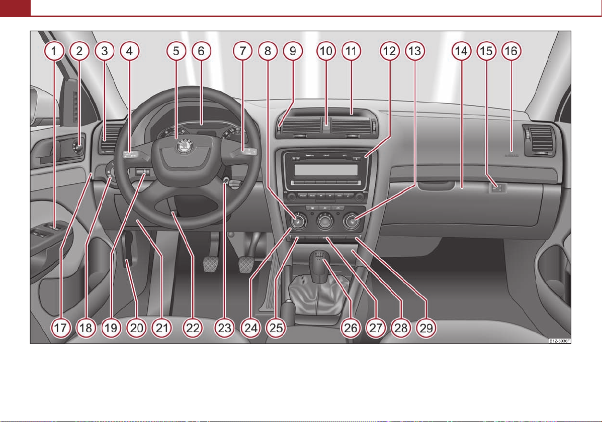
Fig. 1 Certain items of equipment shown in the illustration are only fitted to particular model versions or are optional items of equipment.
Cockpit
Note
A
1
37
A
2
48
A
3
66
A
4
42
77
A
5
90
A
6
15
A
7
18
45
A
8
52
A
9
66
A
10
42
A
11
62
A
12A13
52
A
14
62
A
15
96
A
16
90
A
17
156
A
18
40
A
19
41
A
20
130
A
21
62
A
22
10
A
23
73
A
24
67
69
A
25
106
A
26
76
A
27
109
A
28
60
63
A
29
96
Cockpit 9
Overview
This overview will help you to quickly familiarise yourself with the
displays and the control elements.
Button for automatically opening and closing the windows* . . . . .
Switch for adjusting the exterior mirrors* . . . . . . . . . . . . . . . . . . . . . . .
Air outlet vents . . . . . . . . . . . . . . . . . . . . . . . . . . . . . . . . . . . . . . . . . . . . . . .
Lever for the multi-functional switch:
− Turn signal light, headlight and parking light, headlight flasher
− Cruise control system* . . . . . . . . . . . . . . . . . . . . . . . . . . . . . . . . . . . . . .
Steering wheel:
− with horn
− with driver airbag . . . . . . . . . . . . . . . . . . . . . . . . . . . . . . . . . . . . . . . . . . .
Instrument cluster: Instruments and indicator lights . . . . . . . . . . . .
Lever for the multi-functional switch:
− Multi-functional indicator* . . . . . . . . . . . . . . . . . . . . . . . . . . . . . . . . . .
− Windshield wiper and wash system . . . . . . . . . . . . . . . . . . . . . . . . . .
Control knob for heating on the driver's seat* . . . . . . . . . . . . . . . . . . .
Air outlet vents . . . . . . . . . . . . . . . . . . . . . . . . . . . . . . . . . . . . . . . . . . . . . . .
Button for switching the hazard warning light system on and off
Storage compartment . . . . . . . . . . . . . . . . . . . . . . . . . . . . . . . . . . . . . . . . .
Radio*
Control for heating on the front passenger's seat* . . . . . . . . . . . . . .
Storage compartment on the front passenger side . . . . . . . . . . . . . .
Key-operated switch for activating/deactivating the front passenger
airbag* (in front passenger storage compartment) . . . . . . . . . . . . . .
Front passenger airbag* . . . . . . . . . . . . . . . . . . . . . . . . . . . . . . . . . . . . . . .
Fuse box (on side of dash panel) . . . . . . . . . . . . . . . . . . . . . . . . . . . . . . .
Light switch . . . . . . . . . . . . . . . . . . . . . . . . . . . . . . . . . . . . . . . . . . . . . . . . . .
Control for headlamp beam adjustment . . . . . . . . . . . . . . . . . . . . . . . .
Lever for releasing the bonnet . . . . . . . . . . . . . . . . . . . . . . . . . . . . . . . . .
Storage compartment on the driver's side . . . . . . . . . . . . . . . . . . . . . .
Lever for the adjustable steering column . . . . . . . . . . . . . . . . . . . . . . .
Ignition lock . . . . . . . . . . . . . . . . . . . . . . . . . . . . . . . . . . . . . . . . . . . . . . . . . .
Depending on equipment fitted:
− Controls for the heating . . . . . . . . . . . . . . . . . . . . . . . . . . . . . . . . . . . .
− Controls for Climatic* . . . . . . . . . . . . . . . . . . . . . . . . . . . . . . . . . . . . . . .
Button for switching the Traction Control System (TCS) system on and
off . . . . . . . . . . . . . . . . . . . . . . . . . . . . . . . . . . . . . . . . . . . . . . . . . . . . . . . . . . .
Gearshift lever . . . . . . . . . . . . . . . . . . . . . . . . . . . . . . . . . . . . . . . . . . . . . . .
Tyre inflation pressure-control system* . . . . . . . . . . . . . . . . . . . . . . . .
Depending on equipment fitted:
− Ashtray* . . . . . . . . . . . . . . . . . . . . . . . . . . . . . . . . . . . . . . . . . . . . . . . . . . .
− Storage compartment* . . . . . . . . . . . . . . . . . . . . . . . . . . . . . . . . . . . . .
Indicator light showing deactivated front seat passenger airbag*
• Cars with factory-fitted radio are supplied with separate instructions for oper-
ating such equipment.
• The arrangement of the control elements on right-hand drive models may differ
to some extent from that shown in page 8, fig. 1. However the symbols correspond to the individual control elements.
Using the system Safety Driving Tips General Maintenance Breakdown assistance Technical Data

The brief instruction10
WARNING
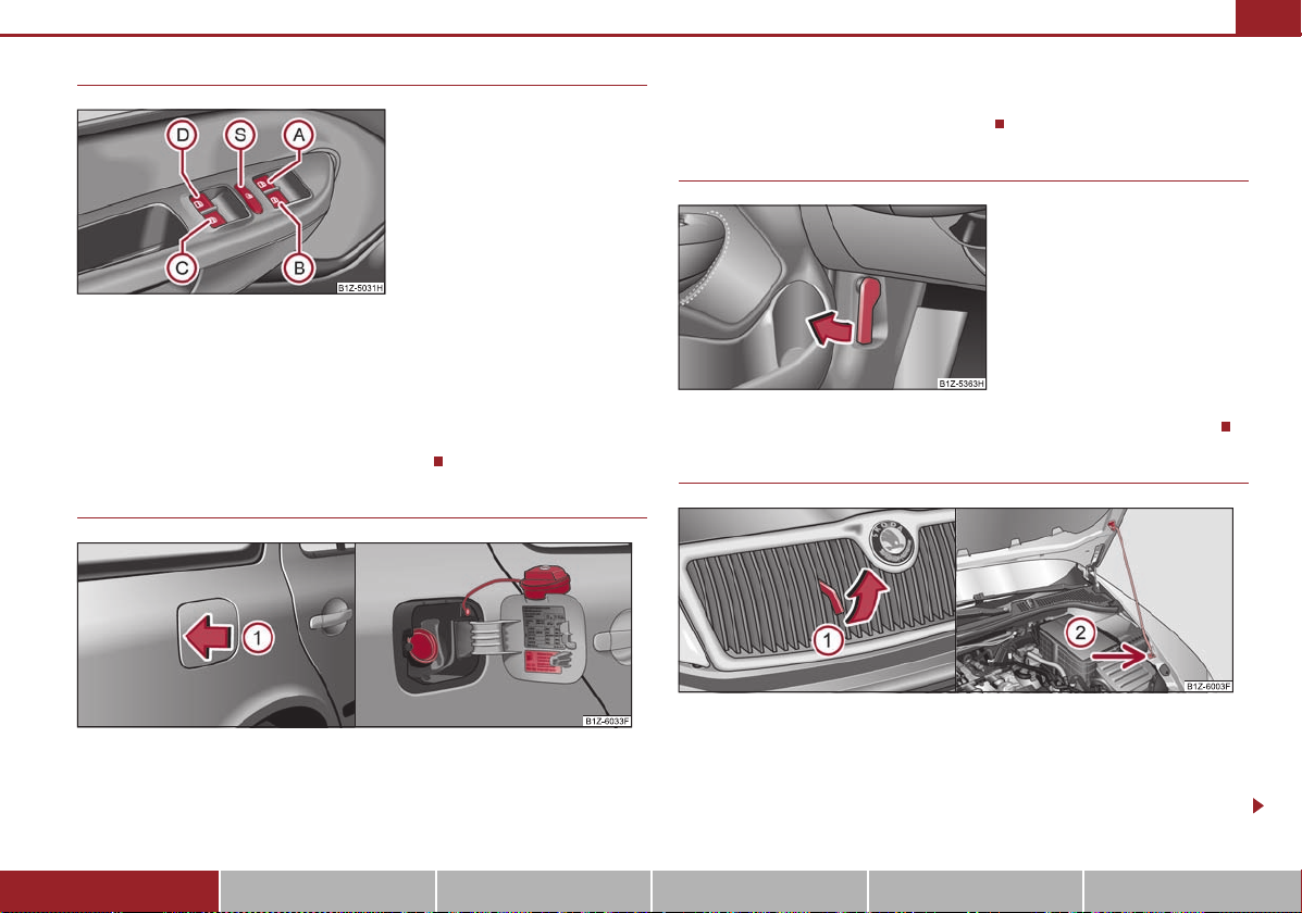
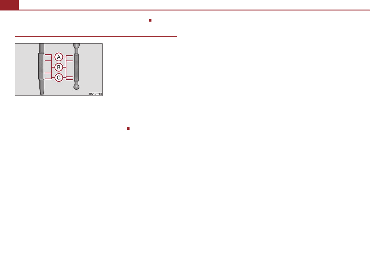
Fig. 2 Remote control key
A1A2A3A
4
The brief instruction
Basic functions and important information
Introduction
The chapter of the brief instruction is only used as a quick reference
of the most important operating elements of the vehicle. It is necessary to observe all the information which is contained in the
following chapters of the Owner's Manual.
Unlocking and locking the vehicle
Unlocking the vehicle
Unlocking the boot lid
Locking the vehicle
Folding out/folding up of the key bit
Further information page 35, “Unlocking and locking the vehicle”.
Setting steering wheel position
Fig. 3 Adjustable steering wheel: Lever on the steering column/the correct distance of the
driver from the steering wheel
You can set the height and the forward/back position of the steering wheel to any
desired position.
– Pull the lever below the steering column down fig. 3 - left.
– Set the steering wheel to the desired position (concerning height and
forward/back position).
– Push the lever upwards as far as the stop.
Further information page 73, “Setting steering wheel position”.
• Adjust the steering wheel so that the distance between the steering wheel
and your chest is at least 25 cm fig. 3 - right. Not maintaining this minimum
distance will mean that the airbag system will not be able to properly protect
you - hazard!
• Only adjust the steering wheel when the car is stationary - danger of acci-
dent!
• For safety reasons the lever must always be firmly pushed up to avoid the
steering wheel altering its position unintentionally when driving - risk of
accident!

The brief instruction 11
WARNING
WARNING
Fig. 4 Front seat: Seat belt height
adjuster
Fig. 5 Controls at seat
A
1
A2A3A
4
Fig. 6 Inner part of door: Rotary knob
Seat belt height adjuster
– Move the height adjuster in the desired direction up or down fig. 4.
– Then pull firmly on the belt to ensure that the seat belt height adjuster has
correctly locked in place.
Further information page 87, “Seat belt height adjuster”.
Adjust the height of the belt in such a way that the shoulder part of the belt is
positioned approximately across the middle of your shoulder - on no account
across your neck!
Adjusting the front seats
Adjusting height of seat*
Adjust the angle of the seat backrest
Adjusting lumbar support*
Further information page 49, “Adjusting the front seats”.
Only adjust the driver seat when the vehicle is stationary - risk of injury!
Electric exterior mirror adjustment*
Heating of the external mirror
Adjusting left and right exterior mirrors simultaneously
Adjusting the right-hand exterior mirror
Switching off operating control
Further information page 48, “Exterior mirror”.
Adjusting a seat in a forward/back direction
Using the system Safety Driving Tips General Maintenance Breakdown assistance Technical Data

The brief instruction12
Fig. 7 Dash panel: Light switch
Fig. 8 Turn signal and main beam lever
AAABACA
D
Fig. 9 Windscreen wiper lever
AAA0A1A2A3A4A5A6A
7
Switching lights on and off
Switching off all lights/daylight driving lights*
Switching on side lights
Switching on the low beam and main beam
Fog lights*
Rear fog light
Further information page 40, “Switching lights on and off ”.
Turn signal and main beam lever
Turn signal light right
Turn signal light left
Switching over between low beam and main beam lights
Headlight flasher
Further information page 42, “The turn signal and main beam lever ”.
Windscreen wiper lever
Intermittent switch
Wipers off
Intermittent wipe
Slow wipe
Fast wipe
one time wipe
Automatic wipe/wash
Rear window wiper*
Intermittent wipe - every 6 seconds
The automatic wiper/washer system
Further information page 45, “Windshield wiper”.
The brief instruction 13
Fig. 10 Buttons on the driver's door
AAABACADASA
1
Fig. 12 Bonnet release lever
A1A
2
Power windows*
Button for the power window in the driver's door
Button for the power window in the front passenger's door
Button for the power window at the rear right door
Button for the power window at the rear left door
Safety pushbutton for deactivating the power window buttons at the rear doors
Further information page 37, “Power windows*”.
Refuelling
– Unscrew the fuel filler cap anti-clockwise and place the fuel filler cap from above
on the fuel filler flap fig. 11 - right.
Further information page 128, “Refuelling”.
Bonnet remote release
– Pull the unlocking lever below the dash panel on the driver's side fig. 12.
Opening the bonnet
Fig. 13 Radiator grille: Release lever/securing the bonnet with the bonnet support
Fig. 11 Right rear side of the vehicle: Open fuel filler flap/fuel filler flap with cap unscrewed
– To open the fuel filler flap, press fig. 11 in the direction of arrow.
– Release the cap by unlocking it by turning the vehicle key to the left.
Using the system Safety Driving Tips General Maintenance Breakdown assistance Technical Data
– Pulling on the release lever in direction of arrow fig. 13 will unlock the
bonnet.
– Take the bonnet support out of its holder and set it in the opening on the
bonnet.
The brief instruction14
Fig. 14 Dipstick
AAABA
C
Further information page 130, “Opening and closing the bonnet.”.
Inspecting the engine oil level
Engine oil must not be refilled.
Engine oil can be refilled.
Engine oil must be refilled.
Further information page 132, “Check engine oil level”.
Instruments and Indicator/Warning Lights
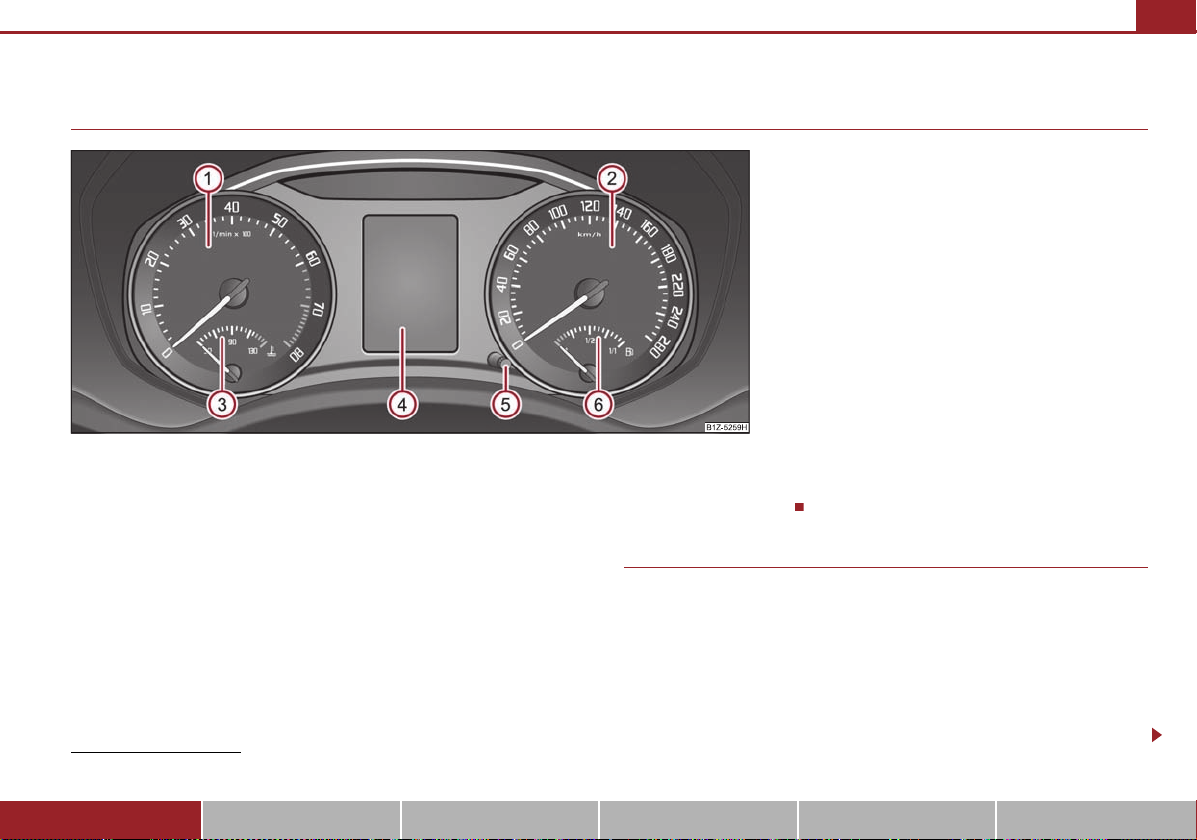
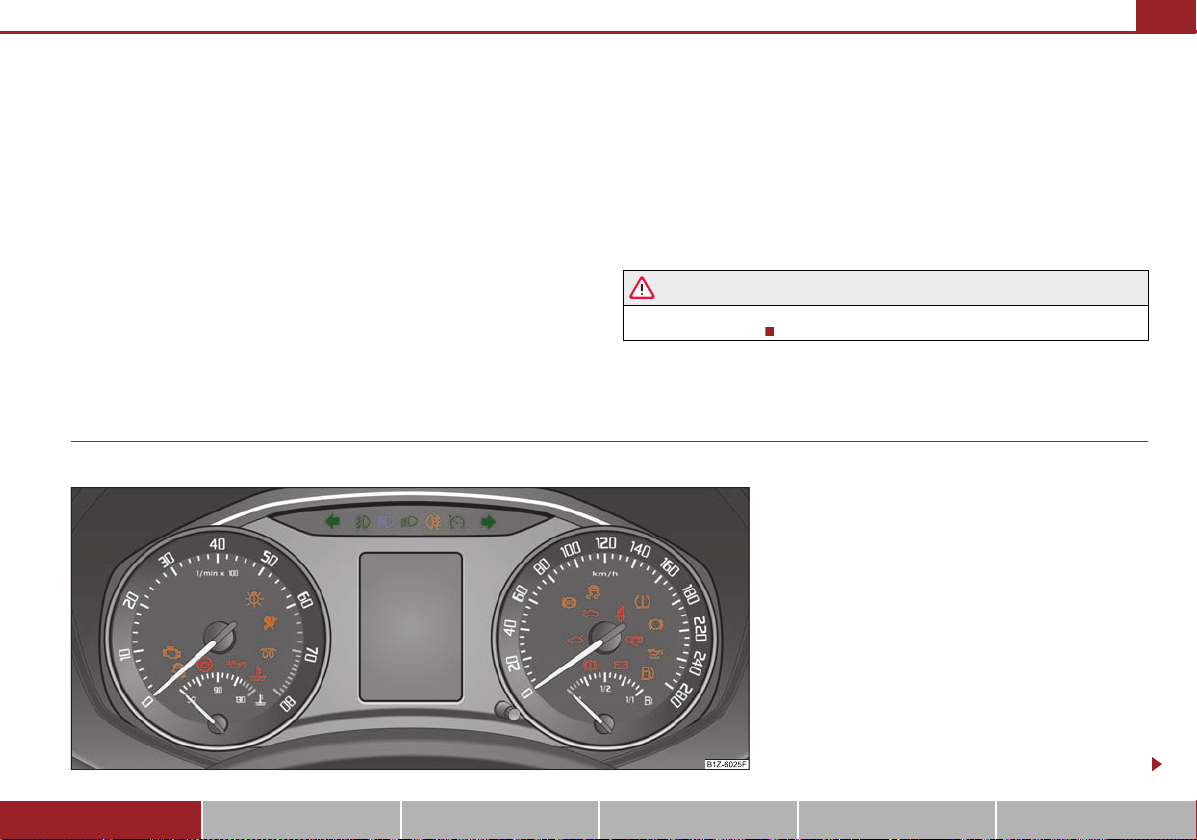
Fig. 15 Instrument cluster
A
1A2A3A4A5A6A1
Overview of the instrument cluster
Instruments and Indicator/Warning Lights 15
Engine revolutions counter page 15
Speedometer page 16
Engine coolant temperature display page 16
Display
− with counter for distance driven page 16
− with Service Interval Display page 17
− with digital clock page 17
− with Multi-functional indicator* page 18
Button for the selection of the mode (turn button)/the setting (press button):
− Set hours/minutes
− Activating/deactivating the second speed in mph or km/h*
− Service interval - Display of the remaining number of days, kilometres or
miles to the next Inspection Service/Reset*
− Reset trip counter for distance driven
1)
Valid for countries where the values are indicated in British measuring units.
Using the system Safety Driving Tips General Maintenance Breakdown assistance Technical Data
1)
− Resetting Service Interval Display
− Activate/deactivate display mode
Fuel gauge page 16
Engine revolutions counter
The red zone in the revolutions counter fig. 15 indicates the maximum permissible engine speed for all gears for an engine which has been run in and operating
at a normal temperature. Before reaching the red zone of the rev counter scale, shift
up into the next higher gear. The engine control unit restricts the engine speed to
a steady limit value.
Before reaching the red zone of the rev counter scale, shift up into the next higher
gear.
Avoid high engine speeds during the driving time and before the engine has
reached operating temperature page 111.
Instruments and Indicator/Warning Lights16
For the sake of the environment
WARNING
Caution
Caution
WARNING
A
3A6A5
Shifting up early helps you save fuel and reduce the operating noise of your
vehicle.
Speedometer
The speedometer shows the current speed of the car.
Fuel gauge
The fuel gauge page 15, fig. 15 only works when the ignition is switched on.
The fuel tank has a capacity of about 55 litres. The warning symbol
ment cluster lights up when the pointer reaches the reserve marking. There are
now about 9 litres of fuel remaining in the tank. This symbol is a reminder for you,
that you must refuel.
An acoustic signal sounds as an additional reminder.
in the instru-
Engine coolant temperature Display
The coolant temperature gauge page 15, fig. 15 operates only when the ignition is switched on.
In order to avoid any damage to the engine, please pay attention to the following
notes regarding the temperature ranges:
Cold range
If the pointer is in the left-hand area of the scale it means that the engine has not
yet reached its operating temperature. Avoid running at high engine speeds, at full
throttle and at severe engine loads.
The operating range
The engine has reached its operating temperature as soon as the pointer moves
into the mid-range of the scale. The pointer may also move further to the right at
high engine loads and high outside temperatures. This is not critical provided the
warning symbol
If the symbol
temperature is too high or the coolant level is too low. Observe the guidelines
page 25, “Coolant temperature/coolant level ”.
Pay attention to the warning notes page 131, “Working in the engine compartment” before opening the bonnet and inspecting the coolant level.
Additional headlights and other attached components in front of the fresh air inlet
impair the cooling efficiency of the coolant. There is then a risk of the engine overheating at high outside temperatures and high engine loads!
in the instrument cluster does not flash.
in the instrument cluster flashes it means that either the coolant
Never run the fuel tank completely empty! The irregular supply of the fuel system
can lead to irregular running of the engine. Unburnt fuel may get into the exhaust
system and damage the catalytic converter.
Counter for distance driven
The distance which you have driven with your vehicle is shown in kilometres (km).
In some countries the measuring unit “mile” is used.
Reset button
Hold the reset button page 15, fig. 15 pressed for approx. 1 second. The trip
counter is reset to zero.
Trip counter for distance driven
The trip counter shows the distance driven since the time the trip counter was last
erased. The trip is shown in steps of 100 metres or 1/10 of a mile.
Odometer
The odometer indicates the total distance in kilometres or miles which the vehicle
has been driven.
Fault display
If there is a fault in the instrument cluster Error will appear in the display. Contact a
specialist garage.
Never seek to adjust the trip counter for distance driven while driving for safety
reasons!
Instruments and Indicator/Warning Lights 17
Note
Caution
Note
WARNING
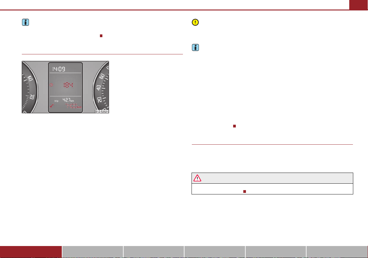
Fig. 16 Service Interval Display: Note
A5A5A
5
If the display of the second speed is activated in mph or km/h, this speed is shown
instead of the odometer on the display.
Service Interval Display
Service Interval Display
Before the next service interval a key symbol
indicated after switching on the ignition fig. 16. At the same time, a display
appears regarding the remaining days until the next service interval.
The kilometre indicator or the days indicator reduces in steps of 100 km. or days
until the service due date is reached.
A flashing key symbol
as soon as the due date for the service is reached.
Resetting Service Interval Display
It is only possible to reset the Service Interval Display, if a service message or at
least a pre-warning is shown on the display of the instrument cluster.
We recommend having this resetting performed by a specialist garage.
The specialist garage:
and the text Service appears in the di splay for 20 seconds
and the remaining kilometres are
• resets the memory of the display after the appropriate inspection,
• makes an entry in the Service schedule,
• affix the sticker with the entry of the following service interval to the side of the
dash panel on the driver's side.
This can be reset as follows: Press the button page 15, fig. 15 and keep it
pressed down, start the ignition, release the button and turn it to the left or right.
We recommend you ask a specialist garage to reset the service interval display.
Incorrectly setting the service interval display can cause problems to the vehicle.
• Never reset the display between service intervals otherwise this may result in
incorrect readouts.
• information is retained in the Service Interval Display also after the battery of
the vehicle is disconnected.
• The service interval display will need to be re-configured if the instrument
cluster is replaced. Contact a specialist garage. This work is carried out by a
specialist garage.
• The data displayed is the same after resetting the display with flexible service
intervals (QG1) using the reset button as that for a vehicle with fixed service intervals (QG2). We therefore recommend having the Service Interval Display reset only
by an authorised Škoda Service Partner who is familiar with the procedure for resetting the display with a vehicle system tester.
• Please refer to the brochure Service schedule for extensive information about
the service intervals.
Digital clock
You can set the time with the rotary knob page 15, fig. 15.
Select the information whic h you wish to change by turning the button and carry
out the change of the selected information by pressing the button.
The clock should not be adjusted while driving for safety reasons but only when
the vehicle is stationary!
Using the system Safety Driving Tips General Maintenance Breakdown assistance Technical Data
Instruments and Indicator/Warning Lights18
Note
Fig. 17 Recommended gear
AAABA
A
Fig. 18 Multi-functional indicator
A
B
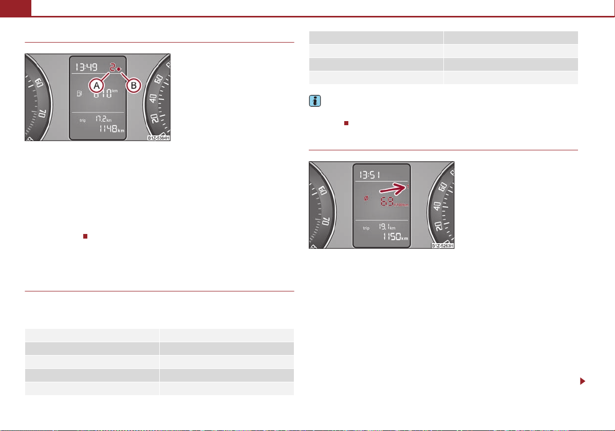
Recommended gear*
An information for the selected gear fig. 17 is shown in the display of the
instrument cluster.
In order to minimise the fuel consumption, a recommendation for shifting into
another gear is indicated in the display.
If the control unit recognises that it is appropriate to change the gear, an arrow
is shown in the display. The arrow points upwards or downwards depending on
whether it is recommended to switch to a higher or lower gear.
At the same time, the recommended gear is indicated instead of the currently
selected gear .
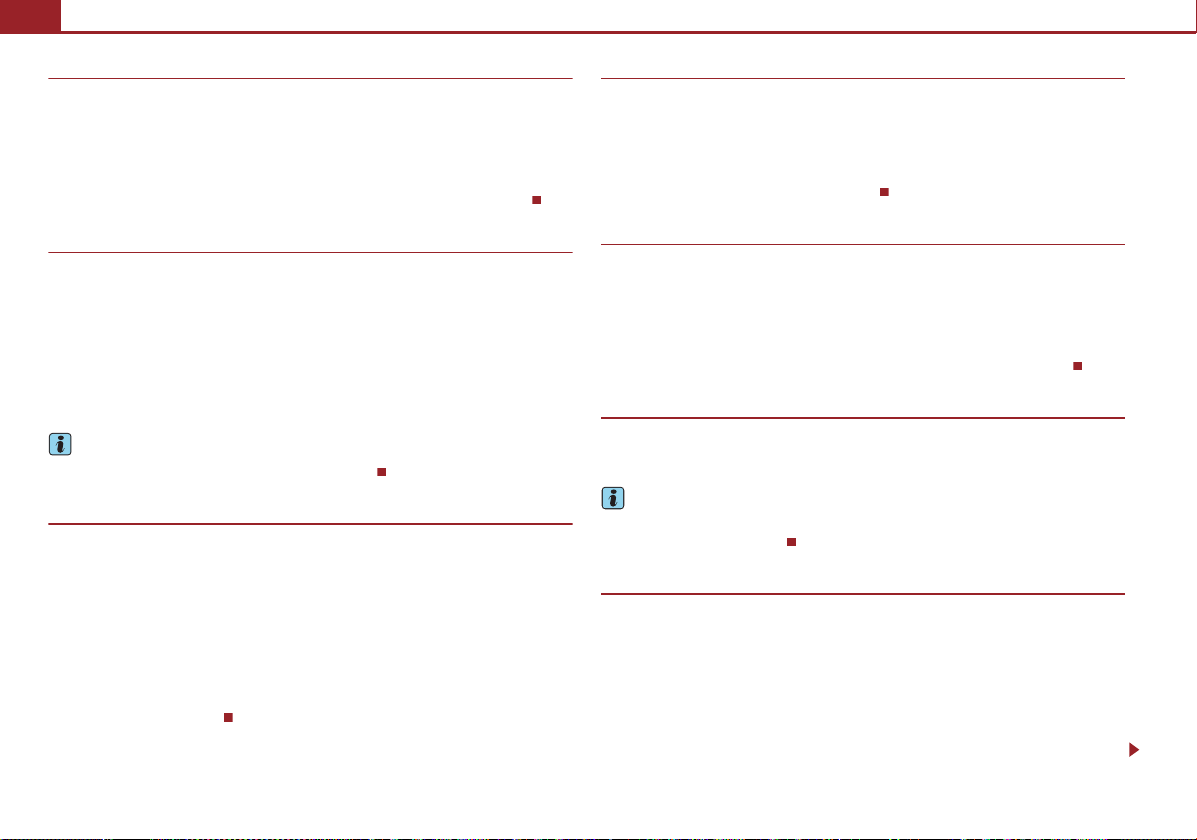
Multi-functional indicator (onboard computer)*
Introduction
This data from the multi-functional indicator appears in the display fig. 18.
The multi-functional indicator offers you a range of useful information.
The outside temperature page 19
Driving time page 19
Current fuel consumption page 20
Average fuel consumption page 20
Range page 20
Distance driven page 20
Average speed page 20
Current speed* page 20
Warning against excessive speeds* page 20
In certain national versions the displays appear in the Imperial system of
measures.
Memory
The multi-functional indicator is equipped with two automatic memories. The
selected memory is displayed in the middle of the display field fig. 18.
The data of the single-trip memory (memory 1) is shown if a 1 appears in the display.
A 2 shown in the display means that data relates to the total distance memory
(memory 2).
Switching over the memory takes place with the button page 19, fig. 19 on the
windshield wiper lever.
Single-trip memory (memory 1)
The single-trip memory collates the driving information from the moment the ignition is switched on until it is switched off. New data will also flow into the calculation of the current driving information if the trip is continued within 2 hours after
switching off the ignition. The memory will be is automatically erased, on the other
hand, if the trip is interrupted for more than 2 hours.

Instruments and Indicator/Warning Lights 19
Note
WARNING
Fig. 19 Multi-functional indicator:
Control elements
ABBABBA
B
Total-trip memory (memory 2)
The total distance driven memory gathers data from any number of individual journeys up to a total of 19 hours and 59 minutes driving or 1.999 kilometres driven. The
memory is deleted when either of these limits is reached and the calculation starts
from anew.
The total-trip memory will not, contrary to the single-trip memory, be deleted after
a period of interruption of driving of 2 hours.
All information in the memory 1 and 2 is erased if the battery of the vehicle is
disconnected.
Operating with the buttons on the windshield wiper lever
The rocker and the button are located in the grip of the window wiper lever
fig. 19.
Selecting the memory
– Tapping the rocker on the windshield wiper lever allows you to select the
desired memory.
Selecting the functions
– Press the rocker up or down. In this way, call up in sequence the individual
functions of the multi-functional indicator.
–Press button .
The following readouts of the selected memory will be set to zero by button :
• average fuel consumption,
• distance driven,
• average speed,
• Driving time.
You can only operate the multi-functional indicator when the ignition is switched
on. After the ignition is switched on, the function disp layed is the one which you last
selected before switching off the ignition.
Outside temperature
The outside temperature appears in the display when the ignition is switched on.
If the outside temperature drops below +4 °C, a snow flake symbol (warning signal
for ice on the road) appears before the temperature indicator and a warning signal
sounds. After pressing the rocker on the windshield wiper lever fig. 19, the
function which was shown last is indicated.
Do not only rely upon the information given on the outside temperature display
that there is no ice on the road. Please note that black ice may also be present
on the road surface even at temperatures around +4 °C - warning, drive with
care!
Driving time
The driving time which has elapsed since the memory was last erased, appears in
the display. If you wish to measure the driving time as of a particular time, you must
set the memory to zero at this moment in time by pressing the button fig. 19
on the windshield wiper lever for longer than 1 second.
The maximum distance indicated in both memories is 19 hours and 59 m inutes. Th e
indicator is set back to null if this period is exceeded.
Setting function to zero
– Select the memory you want.
Using the system Safety Driving Tips General Maintenance Breakdown assistance Technical Data
Instruments and Indicator/Warning Lights20
Note
Note
BBB2A
B
Current consumption
The current fuel consumption level is shown in the display in litres/100 km. This
information can help you to adapt your style of driving to the fuel consumption you
wish to achieve.
The display appears in litres/hour if the vehicle is stationary or driving at a low
speed.
The indicated value will be updated every 0.5 seconds while you are driving.
Average fuel consumption
The average fuel consumption since the memory was last erased is shown in the
display in litres/100 km page 18 . This information can help you to adapt your style
of driving to the fuel consumption you wish to achieve.
If you wish to determine the average fuel consumption over a certain period of time,
you must set the memory at the start of the new measurement to zero using the
button on the windshield wiper lever. A zero appears in the display for the first
100 m you drive after erasing the memory.
The indicated value will be updated every 5 seconds while you are driving.
The amount of fuel consumed will not be indicated.
Range
The estimated range in kilometres is shown on the display. It indicates the distance
you can still drive with your vehicle based on the current level of fuel in the tank for
the same style of driving.
The readout is shown in steps of 10 km. After lighting up of the indicator light for
the fuel reserve the display is shown in steps of 5 km.
The fuel consumption for the last 50 km is taken as a basis for calculating the range.
If you drive in a more economical manner, the range will be increased accordingly.
If the memory is set to zero (after disconnecting the battery), the fuel consumption
of 10 ltr./100 km is calculated for the range; afterwards the value is adapted accordingly to the style of driving.
Distance driven
The distance driven since the memory was last erased appears in the display
page 18. If you wish to calculate the distance driven as of a particular time, you
must erase the memory at this moment in time by pressing the button on the
windshield wiper lever page 19, fig. 19.
The maximum distance indicated in both switch positions is 1,999 km. The indicator
is set back to null if this period is exceeded.
Average speed
The average speed since the memory was last erased is shown in the display in
km/hour page 18. If you wish to determine the average speed over a certain
period of time, you must set the memory at the start of the new measurement to
zero using the button on the windshield wiper lever page 19, fig. 19.
Dashes appear in the display for the first 100 m you drive after erasing the memory.
The indicated value will be updated every 5 seconds while you are driving.
Current speed*
The current speed is displayed on the display. It is identical to the display on the
tachometer (speedometer) page 15, fig. 15.
If the display of the second speed is activated in mph, the current speed* is not indicated in km/h on the display.
Warning against excessive speeds*
This function enables you to set a speed limit and will notify you if you exceed this
speed limit.
Configuring the speed limit while the vehicle is stationary
–With switch page 19, fig. 19, choose the menu point Warning against
excessive speeds.
– Press the switch to activate configuration of the speed limit (the value
flashes).
Instruments and Indicator/Warning Lights 21
WARNING
ABABBAB
B
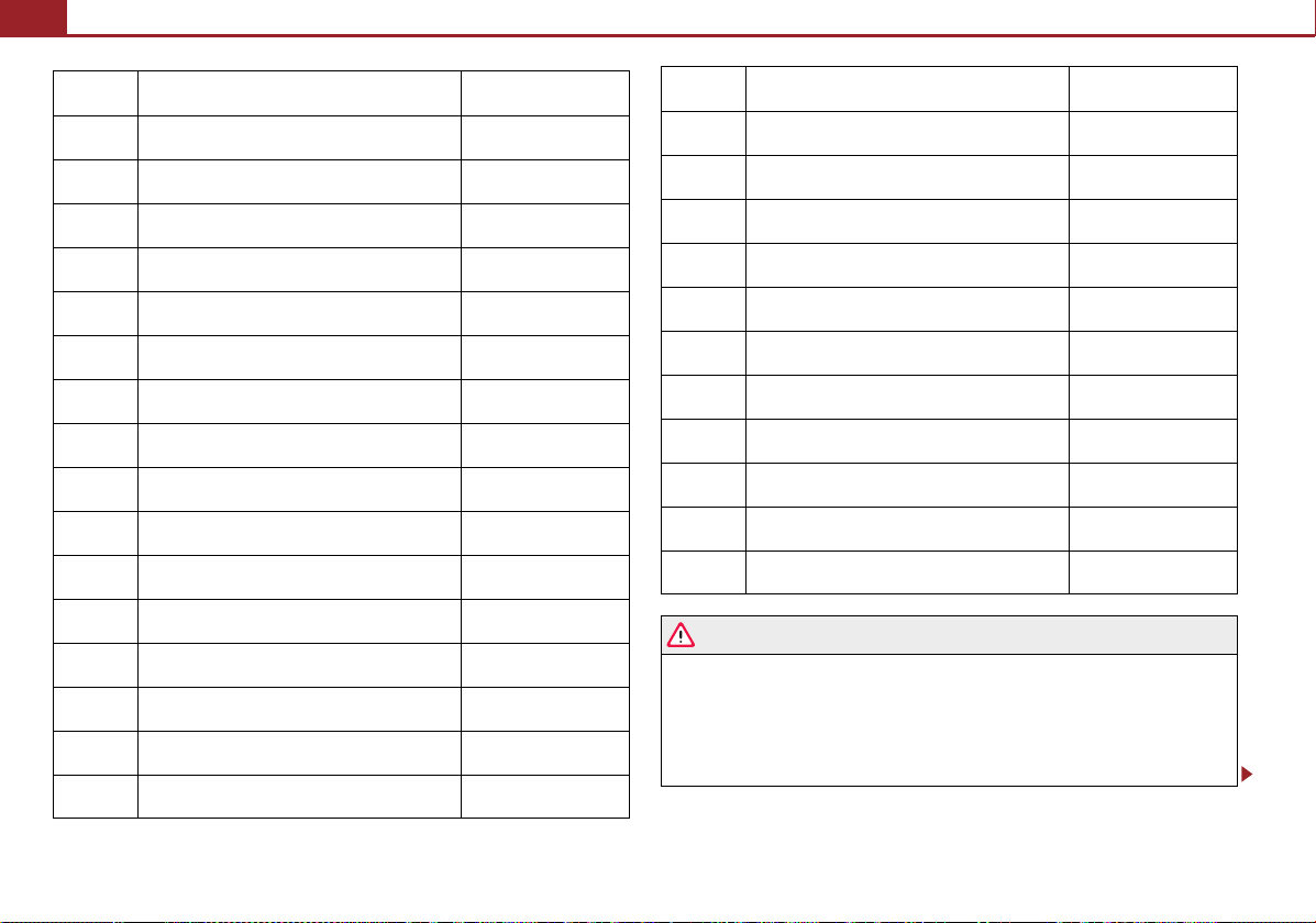
Fig. 20 Instrument cluster with warning lights
– Use switch to set the required speed limit, e.g. 50 km/h.
– Confirm the speed limit that was set with button , or wait 5 seconds until the
setting is saved automatically (the value stops flashing).
In this way you can set the limit in 5 km/h steps.
Configuring the speed limit while the vehicle is moving
– With switch , choose the menu point Warning against excessive speeds.
– Drive e.°g at a speed of 50 km/h.
– Press the switch to accept the current speed as the speed limit (the value
flashes).
If you wish to change the speed limit that was set, it is changed in 5 km/h intervals
(e.g. the accepted speed of 47 km/h increases to 50 km/h or decreases to 45 km/h).
– Confirm the speed limit that was set by pressing button again, or wait 5
seconds until the setting is saved automatically (the value stops flashing).
Warning lights
Overview
The warning lights indicate certain functions or faults.
Changing or erasing the speed limit
– With switch , choose the menu point Warning against excessive speeds.
– When you press the switch again, the speed limit is erased.
– Pressing the switch a further time activates the change mode for the speed
limit.
If you exceed the configured speed, an acoustic signal will sound as a warning. A
Warning against excessive speeds appears together with the set limit on the
display.
The set speed limit remains stored even after switching off the ignition.
Pay attention primarily to the traffic situation! As the driver you are fully responsible for road safety.
Using the system Safety Driving Tips General Maintenance Breakdown assistance Technical Data
Instruments and Indicator/Warning Lights22
WARNING
Turn signal lights (to the left) page 23
Turn signal lights (to the right) page 23
Fog lights* page 23
Main beam light page 23
Low beam light page 23
Rear fog light page 23
Cruise control system* page 23
Failure of the light bulbs page 23
Airbag system page 23
Control system for exhaust page 24
Electromechanical power steering page 24
Engine oil pressure page 24
EPC fault light (petrol engine) page 24
Switch off the Traction control system (TCS); page 25
Tyre pressure* page 26
Antilock brake system (ABS) page 26
Bonnet page 26
Seat belt warning light page 27
Brake pad wear* page 27
Boot lid page 27
Open door page 27
Brake system page 27
Dynamo page 27
Engine oil level page 28
Fuel reserve page 28
Glow plug system (diesel engine) page 24
Coolant temperature/coolant level page 25
Traction control system (TCS) page 25
Electronic stability programme (ESP)* page 25
• If you do not pay attention to the warning lights coming on and the corre-
sponding descriptions and warning notes, this may result in severe body injuries
or major vehicle damage.
• The engine compartment of your car is a hazardous area. There is a risk of
injuries, scalding, accidents and fire when working in the engine compartment,
e.g. inspecting and replenishing oil and other fluids. It is also essential to
observe all warnings page 131, “Working in the engine compartment”.
Note
• The arrangement of the indicator lights depends on the model version. The
symbols shown in the following functional description are to be found as indicator
lights in the instrument cluster.
• Operational faults are shown in the instrument cluster as red symbols (priority 1
- danger) or yellow symbols (priority 2 - warning).
Turn signal system
Either the left or right indicator light flashes depending on the position of the
turn signal lever.
The indicator light flashes at twice its normal rate if a turn signal light fails.
Switching off the hazard warning light system is switched on will cause all of the
turn signal lights as well as both indicator lights to flash.
Further information about the turn signal system page 42.
Fog lights*
The warning light comes on when the fog lights are operating page 41.
Main beam
The indicator light comes on when the main beam is selected or also when the
headlight flasher is operated.
Further information about the main beam page 42.
Low beam
The warning light comes on when low beam is selected page 40.
Rear fog light
The warning light comes on when the rear fog lights are operating page 41.
Instruments and Indicator/Warning Lights 23
Cruise control system*
The warning light lights up, when operating the speed regulating system.
Bulb failure
The warning light comes on if a bulb is faulty:
• up to 2 seconds after the ignition is switched on,
• when switching on the defective light bulb.
The rear side lights and the licence plate lighting require several light bulbs. The
indicator light
parking light (in one rear light unit) are defective. Check regularly the function of the
light bulbs.
only lights up if all light bulbs of the licence plate lighting or the
Airbag system
Monitoring the airbag system
The warning light
There is a fault in the system if the warning light does not go out or flashes while
driving . This also applies if the warning light does not come on when the ignition is switched on.
The functionality of the airbag system is also monitored electronically when one
airbag has been switched off.
Front, side and head airbags or belt tensioner which have been switched off using
the vehicle system tester:
comes on for a few seconds when the ignition is switched on.
• The warning light lights up for 4 seconds after switching on the ignition and
then flashes again for 12 seconds in intervals of 2 seconds.
Front passenger airbags switched off using the switch for front passenger
airbags* in storage compartment on the front passenger side:
• the warning light comes on for 4 seconds after the ignition has been
switched on,
• switching off the airbag is indicated in the middle of the dash panel by the
lighting up of the indicator light
(airbag switched off) page 96.
Using the system Safety Driving Tips General Maintenance Breakdown assistance Technical Data
Instruments and Indicator/Warning Lights24
WARNING
WARNING
Note
WARNING
2
Engine oil pressure
Have the airbag system checked immediately by a specialist garage if a fault
exists. Otherwise, there is a risk of the airbag not being activated in the event
of an accident.
Control system for exhaust
The warning light comes on after the ignition has been switched on.
If the warning light does not go out after starting the engine or it lights up when
driving, a fault exists in an exhaust relevant component. The engine management
system selects an emergency programme which enables you to drive to the nearest
specialist garage by adopting a gentle style of driving.
Electromechanical power steering
The warning light comes on for a few seconds when the ignition is switched on.
If the warning light after switching on the ignition or when driving lights up contin-
uously, a fault exists in the electromechanical power steering.
• If the yellow warning light lights up , this indicates a partial failure of the
power steering and the steering forces can be greater.
• If the red warning light lights up , this indicates a complete failure of the
power steering and the steering assist has failed (significantly higher steering
forces).
Further information page 109.
Contact your specialist garage if the power steering is defective.
• If the yellow warning light goes out after starting the engine again and a
short drive, it is not necessary to visit a specialist garage.
• If the battery has been disconnected and reconnected, the yellow warning light
comes on after switching on the ignition. The warning light must go out after
driving a short distance.
The warning light comes on for a few seconds when the ignition is switched on.
Stop the vehicle and switch the engine off if the warning light does not go off after
the engine has started or flashes while driving. Check the oil level and top up with
oil as necessary page 132, “Replenishing engine oil”.
An audible signal sounds three times as an additional warning signal.
Do not continue your journey if for some reason it is not possible under the condi-
tions prevailing to top up with oil. Keep the engine switched off and obtain professional assistance from a specialist garage, otherwise it could lead to severe engine
damage.
Do not drive any further if the warning light flashes even if the oil is at the correct
level. Do not run the engine not at idling speed either. Contact the nearest specialist
garage to obtain professional assistance.
• If you must stop for technical reasons, then park the vehicle at a safe
distance from the traffic and switch off the engine and switch on the hazard
warning light system.
• The red oil pressure light is not an oil level indicator! One should there-
fore check the oil level at regular intervals, preferably after every refuelling
stop.
EPC fault light (petrol engine)
The (Electronic Power Control) warning light comes on for a few seconds when
the ignition is switched on.
If the warning light
exists in the engine control. The engine management system selects an emergency
programme which enables you to drive to the nearest specialist garage by adopting
a gentle style of driving.
does not go out or lights u p after starting the engine, a fault
Glow plug system (diesel engine)
The warning light lights up for a cold engine when switching on the ignition (preheat position) page 73. Start the engine after the indicator light goes out.
The glow plug indicator light will come on for about 1 second if the engine is at a
WARNING
Note
WARNING (continued)
normal operating temperature or if the outside temperature is above +5 °C. This
means that you can start the engine right away.
There is a fault in the glow plug system if the warning light
at all or lights up continuously. Contact a specialist garage as soon as possible to
obtain assistance.
If the warning light
control. The engine management system selects an emergency programme which
enables you to drive to the nearest specialist garage by adopting a gentle style of
driving.
begins to flash while driving, a fault exists in the engine
does not come on
Coolant temperature/coolant level
The warning light comes on for a few seconds when the ignition is switched on.
The coolant temperature is too high or the coolant level too low if the warning light
does not go out or flashes while driving.
3 peeps sound as an additional warning signal.
In this case stop and switch the engine off and check the coolant level; top up the
coolant as necessary.
Do not continue your journey if for some reason it is not possible under the condi-
tions prevailing to top up with coolant. Keep the engine switched off and obtain
professional assistance from a specialist garage, otherwise it could lead to severe
engine damage.
If the coolant is within the specified range, the increased temperature may be
caused by an operating problem at the coolant fan. Check the fuse for the coolant
fan, replace it if necessary page 157, “Fuse assignment in engine compartment”.
Do not continue driving if the warning light does not go off although the fluid is at
the correct level and also the fuse of the fan is in proper order. Contact a specialist
garage to obtain assistance.
Please also refer to the additional instructions page 133, “Cooling system”.
Instruments and Indicator/Warning Lights 25
• Do not touch the coolant fan The coolant fan may switch on automatically
even if the ignition is off.
Traction control system (TCS)
The warning light comes on for a few seconds when the ignition is switched on.
The warning light flashes when a control cycle is activated while driving.
The warning light lights up permanently if there is a fault in the system.
The fact that the TCS system operates together with the ABS means that the TCS
warning light will also come on if the ABS system is not operating properly.
If the warning light
system can be switched off for technical reasons. In this case, the TCS system can
be switched on again by switching the ignition on and off. If the warning light goes
out, the TCS system is fully functional again.
Further information about the TCS page 106, “Traction control system (TCS)”.
If the battery has been disconnected and reconnected, the warning light comes
on after switching on the ignition. The warning light must go out after driving a
short distance.
comes on immediately after starting the engine, the TCS
Switch off the Traction control system (TCS)
The TCS system is switched off by pressing the button page 106, fig. 112 and the
warning light lights up
.
Electronic stability programme (ESP)*
The warning light comes on for a few seconds when the ignition is switched on.
• If you must stop for technical reasons, then park the vehicle at a safe
distance from the traffic and switch off the engine and switch on the hazard
warning light system page 42.
• Take care when opening the coolant expansion bottle. If the engine is hot,
the cooling system is pressurized - risk of scalding! It is best to allow the engine
to cool down before removing the cap.
Using the system Safety Driving Tips General Maintenance Breakdown assistance Technical Data
When the ESP system is actively helping to stabilise the vehicle, the warning light
in the instrument cluster
The warning light lights up permanently if there is a fault in the ESP system.
The fact that the ESP system operates together with the ABS means that the ESP
warning light will also come on if the ABS system is not operating properly.
flashes quickly.
Instruments and Indicator/Warning Lights26
Note
WARNING
Note
WARNING
If the warning light comes on immediately after starting the engine, the ESP
system can be switched off for technical reasons. In this case, the ESP system can
be switched on again by switching the ignition on and off. If the warning light goes
out, the ESP system is fully functional again.
Further information on the ESP page 105, “Electronic stability programme
(ESP)*”.
Electronic Differential Lock (EDL)*
The EDL is a part of the ESP. A fault in the EDL is indicated by the ESP warning light
in the instrument cluster. Have the vehicle inspected without delay by an authorised Škoda Service Partner. Further information on the EDL page 106, “Electronic
Differential Lock (EDL)*”.
If the battery has been disconnected and reconnected, the warning light comes
on after switching on the ignition. The warning light must go out after driving a
short distance.
Tyre inflation pressure*
The warning light lights up, if there is a substantial drop in inflation pressure in
one of the tyres. Reduce the speed and check or correct as soon as possible the
inflation pressure in the tyres page 141.
If the warning light flashes, there is a system fault. Visit the nearest specialist
garage and have the fault rectified.
Further information about tyre pressure-control system page 109.
• When the warning light lights up, immediately reduce the speed and
avoid sudden steering and brake manoeuvres. Please stop the vehicle without
delay at the nearest possible stop and inspect the tyres and their inflation pressures.
• Under certain circumstances (e.g. sporty style of driving, wintry or unpaved
roads) the warning light
can be delayed or does not light up at all.
Antilock brake system (ABS)
The warning light shows the functionality of the ABS.
The warning light comes on for a few seconds after the ignition has been switched
on or when starting the engine. The warning li ght goes out after an automatic check
sequence has been completed.
A fault in the ABS
The system is not functioning properly if the ABS warning light
within a few seconds after switching on the igni tion, does not light up at all or lights
up while driving. The vehicle will only be braked by the normal brake system. Visit a
specialist garage as quickly as possible and adjust your style of driving appropriately
as you will not know how great the damage is.
Further information about ABS page 108, “Antilock brake system (ABS)”.
A fault in the entire brake system
If the ABS warning light
(handbrake must be released), there is a fault not only in the ABS but also in
another part of the brake system .
• If the brake system warning light comes on together with the ABS
warning light
the reservoir page 135, “Brake fluid”. If the fluid level has dropped below the
MIN marking, do not drive any further - risk of accident! Obtain professional
assistance.
• Pay attention to the following instructions before checking the brake fluid
level and opening the bonnet page 131, “Working in the engine compartment”.
• If the brake fluid is at the correct level, the ABS control function has failed.
The rear wheels may then block very rapidly when braking. In certain circumstances, this can result in the rear end of the car breaking away - risk of skidding!
Drive carefully to the nearest specialist garage and have the fault rectified.
comes on together with the brake system warning light
stop the vehicle immediately and check the brake fluid level in
does not go out
Bonnet
If the battery has been disconnected, the warning light comes on after switching
on the ignition. The warning light must go out after driving a short distance.
The warning light comes on if the bonnet is unlocked. If the bonnet unlocks
while driving, the warning light lights up
sounds.
and as a warning an audible signal
Instruments and Indicator/Warning Lights 27
WARNING
The warning light comes on even when the ignition is switched off. The warning
light lights up for a maximum of 5 minutes.
Seat belt warning light
The warning light comes on after the ignition is switched on as a reminder to
fasten the seat belt. The warning light only goes out if the driver has fastened his
seat belt.
If the seat belt has not been fastened by the driver, a permanent warning signal
sounds at vehicle speeds greater than 20 km/h and simultaneously the warning
light flashes
If the seat belt is not fastened by the driver during the next 90 seconds, the warning
signal is deactivated and the warning light
Further information on the seat belts page 85, “Seat belts”.
.
lights up permanently.
Thickness of the brake pads*
The warning light comes on for a few seconds when the ignition is switched on.
If the warning light
the brake pads on all of the wheels inspected.
comes on, contact a specialist garage immediately and have
Boot lid
The warning light comes on when the ignition is switched on if the luggage
compartment door is open. If the boot lid opens while driving
lights up and an audible signal sounds.
The warning light comes on even when the ignition is switched off. The warning
light lights up for a maximum of 5 minutes.
, the warning light
Open door
The warning light comes on if one or several doors are opened or if the boot lid
is opened. If one of the doors opens while driving, the warning light lights
an audible signal sounds.
The warning light comes on even when the ignition is switched off. The warning
light lights up for a maximum of 5 minutes.
up and
Brake system
The warning light flashes or comes on if the brake fluid level is too low, if there
is a fault in the ABS or if the handbrake is applied.
If the warning light
is not applied), stop and check the brake fluid level .
If there is a fault in the ABS which also influences the function of the brake system
(e.g. distribution of brake pressure), the ABS warning light
same time the brake system warning light starts flashing
the ABS but also another part of the brake system is defective .
An audible signal sounds three times as an additional warning signal.
One should get used to high pedal forces, long braking distances and long free play
of the brake pedal when driving to the next specialist garage.
For further information on the brake system page 107, “Brakes”.
Handbrake applied
The warning light
is also given if you drive the vehicle for at least 3 seconds at a speed of more than
6 km/h.
• Pay attention to the following instructions before checking the brake fluid
level and opening the bonnet page 131, “Working in the engine compartment”.
• If the brake system warning light does not go out a few seconds after
switching on the ignition or comes on when driving, stop immediately and check
the brake fluid in the reservoir page 135. If the fluid level has dropped below
the MIN marking, do not drive any further - risk of accident! Obtain professional
assistance.
flashes and an audible signal sounds three times (handbrake
comes on and at the
. Be aware that not only
also comes on if the handbrake is applied. An audible warning
Alternator
The warning light comes on after the ignition has been switched on. It should go
out after the engine has started.
If the warning light does not go out after the engine has started, or comes on when
driving, drive to the nearest specialist garage. The vehicle battery will be discharged
in this case so switch off all non-essential electrical components.
Using the system Safety Driving Tips General Maintenance Breakdown assistance Technical Data
Instruments and Indicator/Warning Lights28
Caution
If the warning light comes on when driving and in addition the warning light
(cooling system fault) also comes on in display, you must then stop the car immediately and switch the engine off - risk of engine damage!
Engine oil level
Warning light lights up
If the warning light
Check as soon as possible the oil level or top up page 132, “Replenishing engine
oil” with engine oil.
A peep sounds as an additional warning signal.
The warning light will go out if the bonnet is left open for more than 30 seconds. If
no engine oil has been replenished, the warning light will come on again after
driving about 100 km.
Warning light
A fault on the engine oil level sensor is indicated additionally by an audible signal
and the warning light coming on several times after the ignition has been switched
on.
In this case have the engine inspected without delay by a specialist garage.
lig hts u p, the quan tity of oi l in t he en gine i s pro babl y too low.
flashes
Fuel reserve
The warning light comes on, if the fuel level is still below 9 litres.
An audible signal sounds as an additional warning signal.
Unlocking and locking
WARNING
Caution
Note
For the sake of the environment
BA1
2
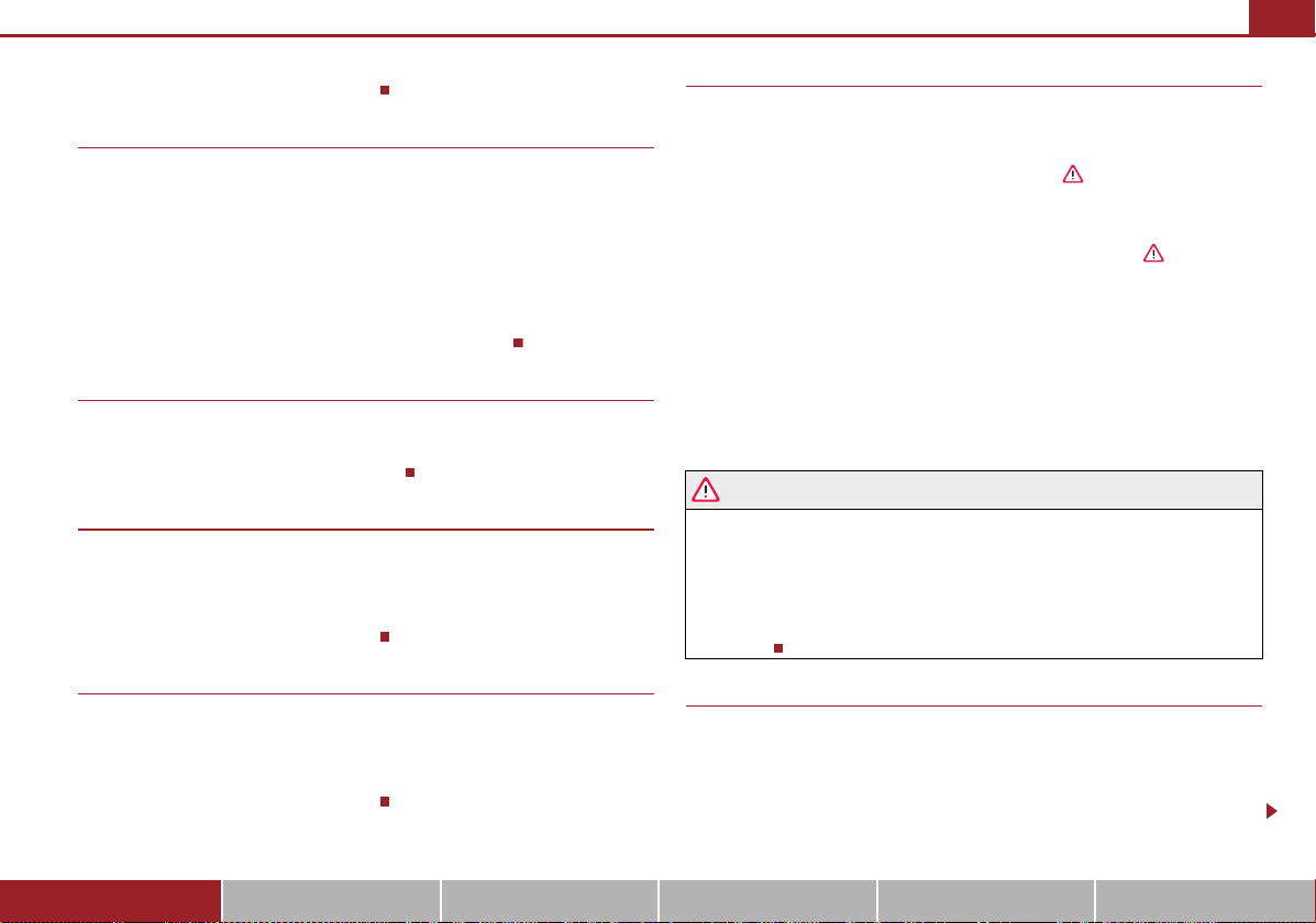
Key
Fig. 21 Set of keys without remote control/set of keys with remote control key
Two keys are provided with the vehicle. Depending on the equipment, your vehicle
can be equipped with keys without radio remote control fig. 21 - left, or with radio
remote control* fig. 21 - right.
• Always withdraw the key whenever you leave the vehicle - even if it is only
for a short time. This is particularly important if children are left in the vehicle.
The children might otherwise start the engine or operate electrical equipment
(e.g. power windows) - risk of injury!
• Do not withdraw the ignition key from the ignition lock until the vehicle has
come to a stop. The steering lock might otherwise engage unintentionally - risk
of accident!
• Each key contains electronic components; therefore protect them against mois-
ture and severe shocks.
• Keep the groove of the keys absolutely clean as impurities (textile fibres, dust
etc.) have a negative effect on the proper operation of the locking cylinder and the
ignition lock.
Unlocking and locking 29
Please approach an authorised Škoda Service Partner if you lose a key since he can
obtain a new one for you.
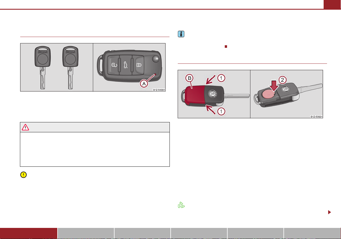
Changing the battery in the remote control key
Fig. 22 Remote control key - remove cover/remove battery
Each remote control key contains a battery which is housed under the cover
fig. 22. If the battery is discharged, the red indicator light does not light up
after pressing a button on the remote control fig. 21. Change the battery as
follows:
– Fold open the key.
– Carefully press off the battery cover at the points of the arrows fig. 22.
– Remove the discharged battery from the key by pressing the battery down-
wards at the point of the arrow fig. 22.
– Insert the new battery. Ensure that the “+” symbol on the battery is facing
upwards. The correct polarity is shown on the battery cover.
– Position the battery cover on the key and press on it until it is heard to lock in
place.
Dispose of a used battery in accordance with environmental regulations.
Using the system Safety Driving Tips General Maintenance Breakdown assistance Technical Data
 Loading...