

Page 1
SIMPLY CLEVER
ŠkodaOctavia Tour
OWNER‘S MANUAL
Page 2

Introduction
You have opted for a Škoda - our sincere thanks for your confidence in us.
Your new Škoda offers you a vehicle featuring the most modern engineering and a wide range of equipment which
you will undoubtedly wish to use to the full during your daily motoring. That is why, we recommend that you read
this Owner's Manual attentively to enable you to become familiar with your car and all that it offers as quickly as
possible.
Please do not hesitate to contact your specialist garage or importer should you have any further questions or any
problems regarding your vehicle which may arise. He will be ready at any time to receive your questions, suggestions and criticisms.
National legal provisions, which deviate from the information contained in these operating instructions, take precedence over the information contained in the operating instructions.
We wish you much pleasure with your Škoda and pleasant motoring at all times.
Yo ur Škoda Auto
Page 3

Introduction2
On-board literature
The on-board literature for your vehicle consists of this “Owner's Manual”
as well as the “Quick Reference Guide”, “Service Schedule” and “Help on
the road”. There can also be a variety of other additional operating manuals
and instructions on-board (e.g. an operating manual for the radio)
depending on the vehicle model and equipment.
If one of the publications listed above is missing, please contact a specialist
garage immediately, where one will be glad to assist you in such matters.
One should note that the details given in the vehicle's papers always
take precedence over those in the Owner's Manual.
Owner's Manual
This Owner's Manual describes the current scope of equipment. Certain
items of equipment listed are only installed later on and only envisaged for
particular markets. The illustrations can differ in minor details from your
vehicle; they are only intended for general information.
In addition to information regarding all the controls and equipment, the
Owner's Manual also contains important information regarding care and
operation for your safety and also to retain the value of your vehicle. To
provide you with valuable tips and aids. You will learn how you can operate
your vehicle safely, economically and in an environmentally conscious
way.
For safety reasons, please also pay attention to the information on
accessories, modifications and replacement of parts page 166.
The other chapters of the Owner's Manual are also important, however, for
proper treatment of your car - in addition to regular care and maintenance
- helps to retain its value and in many cases is also one of the conditions for
possible warranty claims.
The Service schedule
contains:
Vehicle data;
Service intervals;
Overview of the service work;
Service proof;
Confirmation of mobility warranty;
important information on the warranty.
The confirmations of the carried out service work are one of the conditions
for possible warranty claims.
Please always present the Service schedule when you take your car to a
specialist garage.
If the Service schedule is missing or worn, please contact the specialist
garage where your car is serviced regularly. You will receive a duplicate, in
which the previously carried out service work are confirmed.
Help on the road
contains the addresses and telephone numbers of Škoda Importers.
Page 4

Contents
67991010161616161717171819192223253333343434353539
404041
44
46465051525456565759606263687071727374777777798287878788899090919294949497979798102
102
103
103
104
107
108
108
109
111
113
115
115
118
121
123
123
123
125
126
126
127
Contents 3
Layout of this Owner's Manual
(explanations)
. . . . . . . . . . . . . . . . . . . . . . . . . .
Using the system . . . . . . . . . . . . . . . . . . . . . .
Cockpit . . . . . . . . . . . . . . . . . . . . . . . . . . . . . . . . . . . . . . . .
Overview . . . . . . . . . . . . . . . . . . . . . . . . . . . . . . . . . . . .
Quick Reference Guide . . . . . . . . . . . . . . . . . . . . . . .
Basic functions and important information . . . . .
Instruments and warning lights . . . . . . . . . . . . . . .
Overview of the instrument cluster . . . . . . . . . . . . .
Engine revolutions counter . . . . . . . . . . . . . . . . . . . .
Coolant temperature gauge . . . . . . . . . . . . . . . . . . .
Fuel gauge . . . . . . . . . . . . . . . . . . . . . . . . . . . . . . . . . . .
Speedometer . . . . . . . . . . . . . . . . . . . . . . . . . . . . . . . .
Counter for distance driven . . . . . . . . . . . . . . . . . . .
Service Interval Display . . . . . . . . . . . . . . . . . . . . . . .
Digital clock . . . . . . . . . . . . . . . . . . . . . . . . . . . . . . . . . .
Multi-functional indicator (onboard computer)*
Information display* . . . . . . . . . . . . . . . . . . . . . . . . . .
Auto Check Control . . . . . . . . . . . . . . . . . . . . . . . . . . .
Warning lights . . . . . . . . . . . . . . . . . . . . . . . . . . . . . . . .
Unlocking and locking . . . . . . . . . . . . . . . . . . . . . . . .
Key . . . . . . . . . . . . . . . . . . . . . . . . . . . . . . . . . . . . . . . . . .
Changing the battery of the radio remote control
Electronic immobiliser . . . . . . . . . . . . . . . . . . . . . . . .
Locking . . . . . . . . . . . . . . . . . . . . . . . . . . . . . . . . . . . . . .
Child safety lock . . . . . . . . . . . . . . . . . . . . . . . . . . . . . .
Central locking system* . . . . . . . . . . . . . . . . . . . . . . .
Remote control* . . . . . . . . . . . . . . . . . . . . . . . . . . . . . .
Synchronisation of the remote control . . . . . . . . . .
Anti-theft alarm system* . . . . . . . . . . . . . . . . . . . . . .
Power windows* . . . . . . . . . . . . . . . . . . . . . . . . . . . . .
Electric sliding/tilting roof* . . . . . . . . . . . . . . . . . . . .
Lights and Visibility . . . . . . . . . . . . . . . . . . . . . . . . . . . .
Lights . . . . . . . . . . . . . . . . . . . . . . . . . . . . . . . . . . . . . . . .
Interior lighting . . . . . . . . . . . . . . . . . . . . . . . . . . . . . . .
Visibility . . . . . . . . . . . . . . . . . . . . . . . . . . . . . . . . . . . . . .
Windshield wiper and wash system . . . . . . . . . . . . .
Rear-view mirror . . . . . . . . . . . . . . . . . . . . . . . . . . . . . .
Seats and Storage . . . . . . . . . . . . . . . . . . . . . . . . . . . . . .
Front seats . . . . . . . . . . . . . . . . . . . . . . . . . . . . . . . . . . . .
Adjusting front seats electrically* . . . . . . . . . . . . . . .
Head restraints . . . . . . . . . . . . . . . . . . . . . . . . . . . . . . . .
Rear seats . . . . . . . . . . . . . . . . . . . . . . . . . . . . . . . . . . . .
Pedals . . . . . . . . . . . . . . . . . . . . . . . . . . . . . . . . . . . . . . . .
luggage compartment . . . . . . . . . . . . . . . . . . . . . . . . .
Net partition (Combi)* . . . . . . . . . . . . . . . . . . . . . . . .
The roof rack* . . . . . . . . . . . . . . . . . . . . . . . . . . . . . . . .
Note holder . . . . . . . . . . . . . . . . . . . . . . . . . . . . . . . . . .
Ashtray* . . . . . . . . . . . . . . . . . . . . . . . . . . . . . . . . . . . . . .
Cigarette lighter*, power sockets . . . . . . . . . . . . . . .
Storage compartments . . . . . . . . . . . . . . . . . . . . . . . .
Heating and air conditioning system . . . . . . . . . .
Air outlet vents . . . . . . . . . . . . . . . . . . . . . . . . . . . . . . . .
Heating . . . . . . . . . . . . . . . . . . . . . . . . . . . . . . . . . . . . . .
Air conditioning system* . . . . . . . . . . . . . . . . . . . . . .
Climatronic* (automatic air conditioning) . . . . . . .
Starting-off and Driving . . . . . . . . . . . . . . . . . . . . . . .
Setting steering wheel position . . . . . . . . . . . . . . . . .
Ignition lock . . . . . . . . . . . . . . . . . . . . . . . . . . . . . . . . . .
Starting the engine . . . . . . . . . . . . . . . . . . . . . . . . . . . .
Switching off the engine . . . . . . . . . . . . . . . . . . . . . . .
Shifting . . . . . . . . . . . . . . . . . . . . . . . . . . . . . . . . . . . . . . .
Handbrake . . . . . . . . . . . . . . . . . . . . . . . . . . . . . . . . . . .
Rear parking aid* . . . . . . . . . . . . . . . . . . . . . . . . . . . . .
Cruise control system (CCS)* . . . . . . . . . . . . . . . . . . .
Communication . . . . . . . . . . . . . . . . . . . . . . . . . . . . . . .
Mobile phone, handsfree-system* . . . . . . . . . . . . .
Mobile phones and two-way radio systems . . . . .
Safety . . . . . . . . . . . . . . . . . . . . . . . . . . . . . . . . . . . . . . .
Passive Safety . . . . . . . . . . . . . . . . . . . . . . . . . . . . . . . . .
Basic information . . . . . . . . . . . . . . . . . . . . . . . . . . . . .
Correct seated position . . . . . . . . . . . . . . . . . . . . . . .
Seat belts . . . . . . . . . . . . . . . . . . . . . . . . . . . . . . . . . . . . . .
Why seat belts? . . . . . . . . . . . . . . . . . . . . . . . . . . . . . . .
The physical principle of a frontal collision . . . . . .
Important safety information regarding the use of seat
belts . . . . . . . . . . . . . . . . . . . . . . . . . . . . . . . . . . . . . . . . .
How are seat belts correctly fastened? . . . . . . . . . .
Belt tensioners . . . . . . . . . . . . . . . . . . . . . . . . . . . . . . .
Airbag system . . . . . . . . . . . . . . . . . . . . . . . . . . . . . . . . .
Description of the airbag system . . . . . . . . . . . . . . .
Front airbags . . . . . . . . . . . . . . . . . . . . . . . . . . . . . . . . .
Side airbags* . . . . . . . . . . . . . . . . . . . . . . . . . . . . . . . . .
Deactivating an airbag . . . . . . . . . . . . . . . . . . . . . . . .
Transporting children safely . . . . . . . . . . . . . . . . . .
What you should know about transporting children!
Child seat . . . . . . . . . . . . . . . . . . . . . . . . . . . . . . . . . . . .
Attaching a child seat using the “ISOFIX” system .
Driving Tips . . . . . . . . . . . . . . . . . . . . . . . . . . . . . .
Intelligent Technology . . . . . . . . . . . . . . . . . . . . . . . .
Electronic stability programme (ESP)* . . . . . . . . . .
Brakes . . . . . . . . . . . . . . . . . . . . . . . . . . . . . . . . . . . . . . .
Brake booster . . . . . . . . . . . . . . . . . . . . . . . . . . . . . . . .
Antilock brake system (ABS)* . . . . . . . . . . . . . . . . . .
Brake Assist* . . . . . . . . . . . . . . . . . . . . . . . . . . . . . . . . .
Using the system Safety Driving Tips General Maintenance Breakdown assistance Technical Data
Page 5

Contents4
128
128
129
129
132
133
133
134
134
136
137
137
137
137
142
144
144
144
145
147
147
149
152
154
155
159
160
160
166
166
166
166
167
167
167
167
167
168
168
168
169
173
174
177
177
180
187
187
187
187
187
187
187
188
189
190
192
193
196
198
198
199
Driving and the Environment . . . . . . . . . . . . . . . . .
The first 1 500 kilometres and then afterwards . .
Catalytic converter . . . . . . . . . . . . . . . . . . . . . . . . . . . .
Driving in an economical and environmentally
conscious manner . . . . . . . . . . . . . . . . . . . . . . . . . . . .
Environmental compatibility . . . . . . . . . . . . . . . . . . .
Motoring abroad . . . . . . . . . . . . . . . . . . . . . . . . . . . . .
Avoiding damage to your vehicle . . . . . . . . . . . . . .
Towing a trailer . . . . . . . . . . . . . . . . . . . . . . . . . . . . . . . .
Towing a trailer . . . . . . . . . . . . . . . . . . . . . . . . . . . . . . .
Detachable towing device* . . . . . . . . . . . . . . . . . . . .
General Maintenance . . . . . . . . . . . . . . .
Taking care of your vehicle and cleaning the
vehicle . . . . . . . . . . . . . . . . . . . . . . . . . . . . . . . . . . . . . . . . .
General . . . . . . . . . . . . . . . . . . . . . . . . . . . . . . . . . . . . . .
Care of the exterior of vehicle . . . . . . . . . . . . . . . . . .
Care of the interior of vehicle . . . . . . . . . . . . . . . . . .
Fuel . . . . . . . . . . . . . . . . . . . . . . . . . . . . . . . . . . . . . . . . . . . .
Petrol . . . . . . . . . . . . . . . . . . . . . . . . . . . . . . . . . . . . . . . .
Diesel . . . . . . . . . . . . . . . . . . . . . . . . . . . . . . . . . . . . . . .
Refuelling . . . . . . . . . . . . . . . . . . . . . . . . . . . . . . . . . . . .
Inspecting and replenishing . . . . . . . . . . . . . . . . . .
Engine compartment . . . . . . . . . . . . . . . . . . . . . . . . .
Engine oil . . . . . . . . . . . . . . . . . . . . . . . . . . . . . . . . . . . .
Cooling system . . . . . . . . . . . . . . . . . . . . . . . . . . . . . . .
Brake fluid . . . . . . . . . . . . . . . . . . . . . . . . . . . . . . . . . . .
Battery . . . . . . . . . . . . . . . . . . . . . . . . . . . . . . . . . . . . . . .
Windshield washer system . . . . . . . . . . . . . . . . . . . .
Wheels and Tyres . . . . . . . . . . . . . . . . . . . . . . . . . . . . .
Wheels . . . . . . . . . . . . . . . . . . . . . . . . . . . . . . . . . . . . . .
Accessories, changes and replacement of parts
Accessories and replacement parts . . . . . . . . . . . .
Technical changes . . . . . . . . . . . . . . . . . . . . . . . . . . . .
Vehicles of category N1 . . . . . . . . . . . . . . . . . . . . . . .
Breakdown assistance . . . . . . . . . . . . . .
Breakdown assistance . . . . . . . . . . . . . . . . . . . . . . . . .
First-aid box*, Warning triangle* and bulb set* . .
Fire extinguisher* . . . . . . . . . . . . . . . . . . . . . . . . . . . . .
Vehicle tool kit . . . . . . . . . . . . . . . . . . . . . . . . . . . . . . . .
Spray for repairing a tyre* . . . . . . . . . . . . . . . . . . . . . .
Tyre repair kit* . . . . . . . . . . . . . . . . . . . . . . . . . . . . . . . .
Spare wheel* . . . . . . . . . . . . . . . . . . . . . . . . . . . . . . . . .
Changing a wheel . . . . . . . . . . . . . . . . . . . . . . . . . . . . .
Jump-starting . . . . . . . . . . . . . . . . . . . . . . . . . . . . . . . . .
Tow-starting and towing vehicle . . . . . . . . . . . . . . . .
Fuses and light bulbs . . . . . . . . . . . . . . . . . . . . . . . . . .
Electric fuses . . . . . . . . . . . . . . . . . . . . . . . . . . . . . . . . . .
Bulbs . . . . . . . . . . . . . . . . . . . . . . . . . . . . . . . . . . . . . . . . .
Technical Data . . . . . . . . . . . . . . . . . . . . . . . . . .
Technical Data . . . . . . . . . . . . . . . . . . . . . . . . . . . . . . . . .
General information . . . . . . . . . . . . . . . . . . . . . . . . . . .
Used abbreviations . . . . . . . . . . . . . . . . . . . . . . . . . . . .
Performances . . . . . . . . . . . . . . . . . . . . . . . . . . . . . . . . .
Weight . . . . . . . . . . . . . . . . . . . . . . . . . . . . . . . . . . . . . . .
Identification details . . . . . . . . . . . . . . . . . . . . . . . . . . .
Fuel consumption according to the ECE standards and
EU guidelines . . . . . . . . . . . . . . . . . . . . . . . . . . . . . . . . .
Dimensions . . . . . . . . . . . . . . . . . . . . . . . . . . . . . . . . . .
1.4 ltr./55 kW - EU4 . . . . . . . . . . . . . . . . . . . . . . . . . . . .
1.6 ltr./75 kW - EU4/EU2 DDK . . . . . . . . . . . . . . . . . .
1.8 ltr./110 kW - EU4/EU3D . . . . . . . . . . . . . . . . . . . .
1.9 ltr./74 kW TDI PD - EU4 . . . . . . . . . . . . . . . . . . . . .
Octavia - Vehicles of the group N1 . . . . . . . . . . . . . .
Octavia Combi - Vehicles of the group N1 . . . . . . .
Index . . . . . . . . . . . . . . . . . . . . . . . . . . . . . . . . . . . . . . . .
Page 6

Contents 5
Using the system Safety Driving Tips General Maintenance Breakdown assistance Technical Data
Page 7
Layout of this Owner's Manual (explanations)6
WARNING
Caution
For the sake of the environment
Note
Layout of this Owner's Manual (explanations)
The Owner's Manual has been systematically designed, in order to make it easy for you
to find and absorb the information you require.
Chapters, table of contents and subject index
The text of the Owner's manual is divided into relatively short sections which are
combined into easy-to-read chapters. The chapter you are reading at any particular
moment is highlighted at the bottom right of the page.
The Table of contents is arranged according to the chapters and the detailed Subject
index at the end of the Owner's Manual helps you to rapidly find the information you
are looking for.
Sections
The majority of Sections apply to all models.
Since there is a wide range of different equipment and options available it is clearly
unavoidable, despite dividing the contents into sections, that mention may be made
of equipment which is not fitted to your vehicle.
Brief information and instructions
Each section has a Heading.
This is followed by Brief information (in large italic lettering), which tells you the
subject which is dealt with in this section.
Most of the illustrations are accompanied by an Instruction (in relatively large letters)
which explains to you in a straightforward way the action you have to take. Work steps
which have to be carried out are illustrated with a hyphen.
Direction indications
All direction indications such as “left”, “right”, “front”, “rear” relate to the direction of
travel of the vehicle.
Explanation of symbols
* Equipment which is marked in such a way is only standard on certain vehicle model
versions or only suppliable as optional equipment for certain models.
End of a section.
The section is continued on the next page.
Notes
All four kinds of notes, which are used in the text, are always stated at the end of the
respective section.
The most important notes are marked with the heading WARNING. These
WARNING notes draw your attention to a serious risk of accident or injury.
While reading the text you will frequently encounter a double arrow followed
by a small warning symbol. This symbol is intended to draw your attention to a
WARNING note at the end of the section to which you must pay careful attention.
A Caution note draws your attention to the possibility of damage to your vehicle (e.g.
damage to gearbox), or points out general risks of an accident.
An Environmental note draws your attention to environmental protection aspects.
This is where you will, for example, find tips aimed at reducing your fuel consumption.
A normal Note draws your attention in a general way to important information.
Page 8

Using the system
7
Using the system Safety Driving Tips General Maintenance Breakdown assistance Technical Data
Page 9
Cockpit8
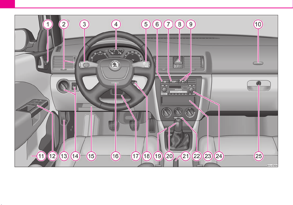
Fig. 1 Certain items of equipment shown in the illustration are only fitted to particular model versions or are optional items of equipment.
Page 10
Cockpit
Note
A
1
54
A
2
77
A
3
49
92
A
4
16
A
5
19
52
A
6
A
7
123
125
A
8
48
A
9
62
A
10
109
A
11A12
37, 41
A
13
147
A
14
46, 48
A15A
16
109
A
17
87
A
18
87
A
19
72
A
20
90
A
21
90
A
22
777982
A
23A24A25
74
Cockpit 9
Overview
This overview will help you to quickly familiarise yourself with the
displays and the control elements.
Electric exterior mirror adjustment* . . . . . . . . . . . . . . . . . . . . . . . . . . . . .
Air outlet vents . . . . . . . . . . . . . . . . . . . . . . . . . . . . . . . . . . . . . . . . . . . . . . . .
Lever for the multi-functional switch:
Turn signal light, headlight and parking light, headlight flasher . .
Speed regulating system* . . . . . . . . . . . . . . . . . . . . . . . . . . . . . . . . . . . .
Instrument cluster: Instruments and indicator lights . . . . . . . . . . . . . .
Lever for the multi-functional switch:
Multi-functional indicator* . . . . . . . . . . . . . . . . . . . . . . . . . . . . . . . . . . .
Windshield wiper and wash system . . . . . . . . . . . . . . . . . . . . . . . . . . .
Switch for rear window heater
Depending on equipment fitted:
Switch for the ESP* . . . . . . . . . . . . . . . . . . . . . . . . . . . . . . . . . . . . . . . . . .
Switch for the TCS* . . . . . . . . . . . . . . . . . . . . . . . . . . . . . . . . . . . . . . . . . .
Switch for hazard warning lights . . . . . . . . . . . . . . . . . . . . . . . . . . . . . . . . .
Control dial for heating on the driver and front passenger seat* . . .
Front passenger airbag* . . . . . . . . . . . . . . . . . . . . . . . . . . . . . . . . . . . . . . . .
Storage compartment in the front door
Central locking switch and power windows* . . . . . . . . . . . . . . . . . . . . .
Bonnet release lever . . . . . . . . . . . . . . . . . . . . . . . . . . . . . . . . . . . . . . . . . . .
Light switch, headlamp beam adjustment . . . . . . . . . . . . . . . . . . . . . . . .
Storage compartment below steering wheel
Steering wheel:
with horn
with driver airbag . . . . . . . . . . . . . . . . . . . . . . . . . . . . . . . . . . . . . . . . . . .
Lever for adjusting the steering wheel . . . . . . . . . . . . . . . . . . . . . . . . . . .
Ignition lock . . . . . . . . . . . . . . . . . . . . . . . . . . . . . . . . . . . . . . . . . . . . . . . . . . .
Ashtrays . . . . . . . . . . . . . . . . . . . . . . . . . . . . . . . . . . . . . . . . . . . . . . . . . . . . . . .
Gearshift lever (manual gearbox) . . . . . . . . . . . . . . . . . . . . . . . . . . . . . . . .
Handbrake . . . . . . . . . . . . . . . . . . . . . . . . . . . . . . . . . . . . . . . . . . . . . . . . . . . . .
Depending on equipment fitted:
Operating controls for the heating . . . . . . . . . . . . . . . . . . . . . . . . . . . .
Operating controls for the air conditioning system* . . . . . . . . . . . .
Operating controls for Climatronic* . . . . . . . . . . . . . . . . . . . . . . . . . . .
Storage compartment in the middle part of the dash panel
Radio*
Storage compartment on the front passenger side . . . . . . . . . . . . . . . .
Equipment which is marked * is only standard on certain vehicle model versions
or only suppliable as optional equipment for certain models.
Vehicles with factory-fitted radio, mobile phone etc, are supplied with separate
instructions for operating such equipment.
The arrangement of the control elements on right-hand drive models may differ to
some extent from that shown in page 8, fig. 1. However the symbols correspond to
the individual control elements.
Using the system Safety Driving Tips General Maintenance Breakdown assistance Technical Data
Page 11
Quick Reference Guide10
WARNING
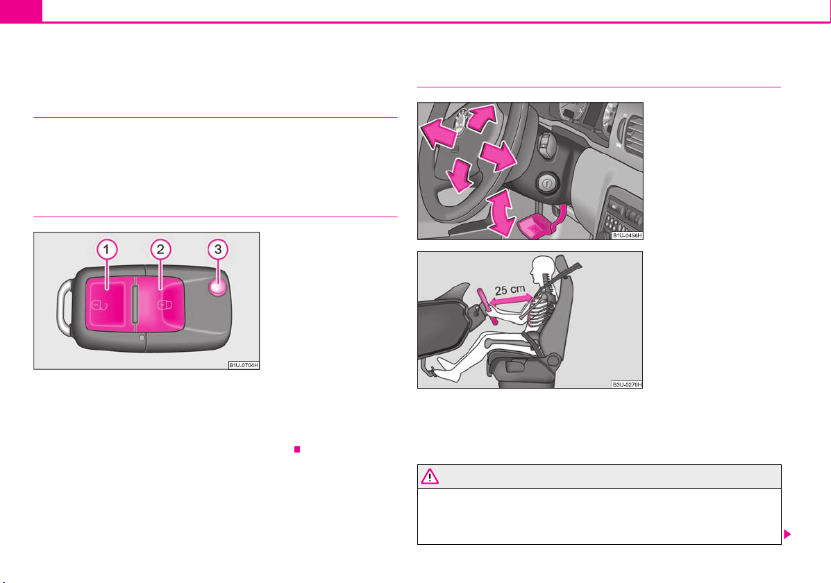
Fig. 2 Remote control key
A1A2A
3
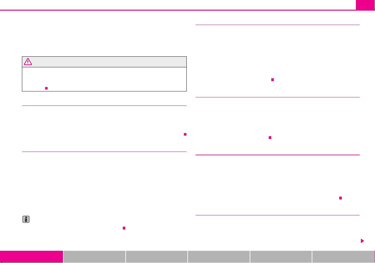
Fig. 3 Adjustable steering
wheel: Lever on the steering
column
Fig. 4 The correct distance of the
driver from the steering wheel
Quick Reference Guide
Basic functions and important information
Introduction
The chapter of the brief instruction is only used as a quick reference of
the most important operating elements of the vehicle. It is necessary to
observe all the information which is contained in the following chapters
of the Owner's Manual.
Unlocking and locking the vehicle
Unlocking the vehicle
Locking the vehicle
Folding out/folding up of the key
Further information page 39, “Unlocking and locking car”.
Setting steering wheel position
You can set the height and the forward/back position of the steering wheel to the
desired position.
Further information page 87, “Setting steering wheel position”.
Adjust the steering wheel so that the distance between the steering wheel
and your chest is at least 25 cm fig. 4. Not maintaining this minimum
distance will mean that the airbag system will not be able to properly protect
you - hazard!
Page 12
You must not adjust the steering wheel when the vehicle is moving!
WARNING
WARNING
WARNING (continued )
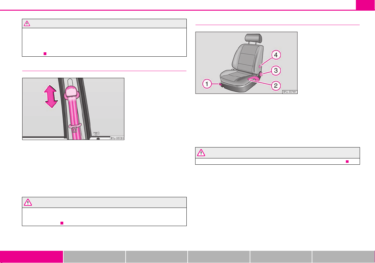
Fig. 5 Front seat: Seat belt
height adjuster
Fig. 6 Controls at seat
A1A2A3A
4
For safety reasons the lever must always be firmly pushed up to avoid the
steering wheel altering its position unintentionally when driving - risk of
accident!
Seat belt height adjuster
– In order to adjust the height, press on the upper seat belt deflection and push it
into the desired direction up or down so that the shoulder part of the belt is positioned approximately across the middle of your shoulder.
– Then pull firmly on the belt to ensure that the seat belt height adjuster has correctly
locked in place.
Further information page 105, “Seat belt height adjuster”.
Quick Reference Guide 11
Adjusting the front seats
Adjusting a seat in a forward/back direction
Adjusting height of seat*
Adjust the angle of the seat backrest
Adjusting lumbar support*
Further information page 56, “Adjusting the front seats”.
Only adjust the driver seat when the vehicle is stationary - risk of injury!
Adjust the height of the belt in such a way that the shoulder part of the belt is
positioned approximately across the middle of your shoulder - on no account
across your neck!
Using the system Safety Driving Tips General Maintenance Breakdown assistance Technical Data
Page 13
Quick Reference Guide12
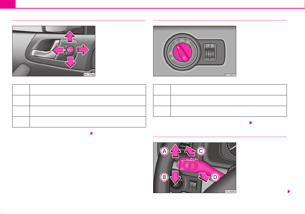
Fig. 7 Inner part of door: Rotary
knob
Fig. 8 Dash panel: Light switch
Fig. 9 Turn signal and main
beam lever
Electric exterior mirror adjustment*
Heating of the external mirror
Adjusting left and right exterior mirrors simultaneously
Adjusting the right-hand exterior mirror
Switching off operating control
Further information page 54, “Exterior mirror”.
Switching lights on and off
Switching off all lights
Switching on side lights
Switching on the low beam and main beam
Further information page 46, “Switching lights on and off”.
Turn signal and main beam lever
Page 14
Quick Reference Guide 13
AAABACA
D
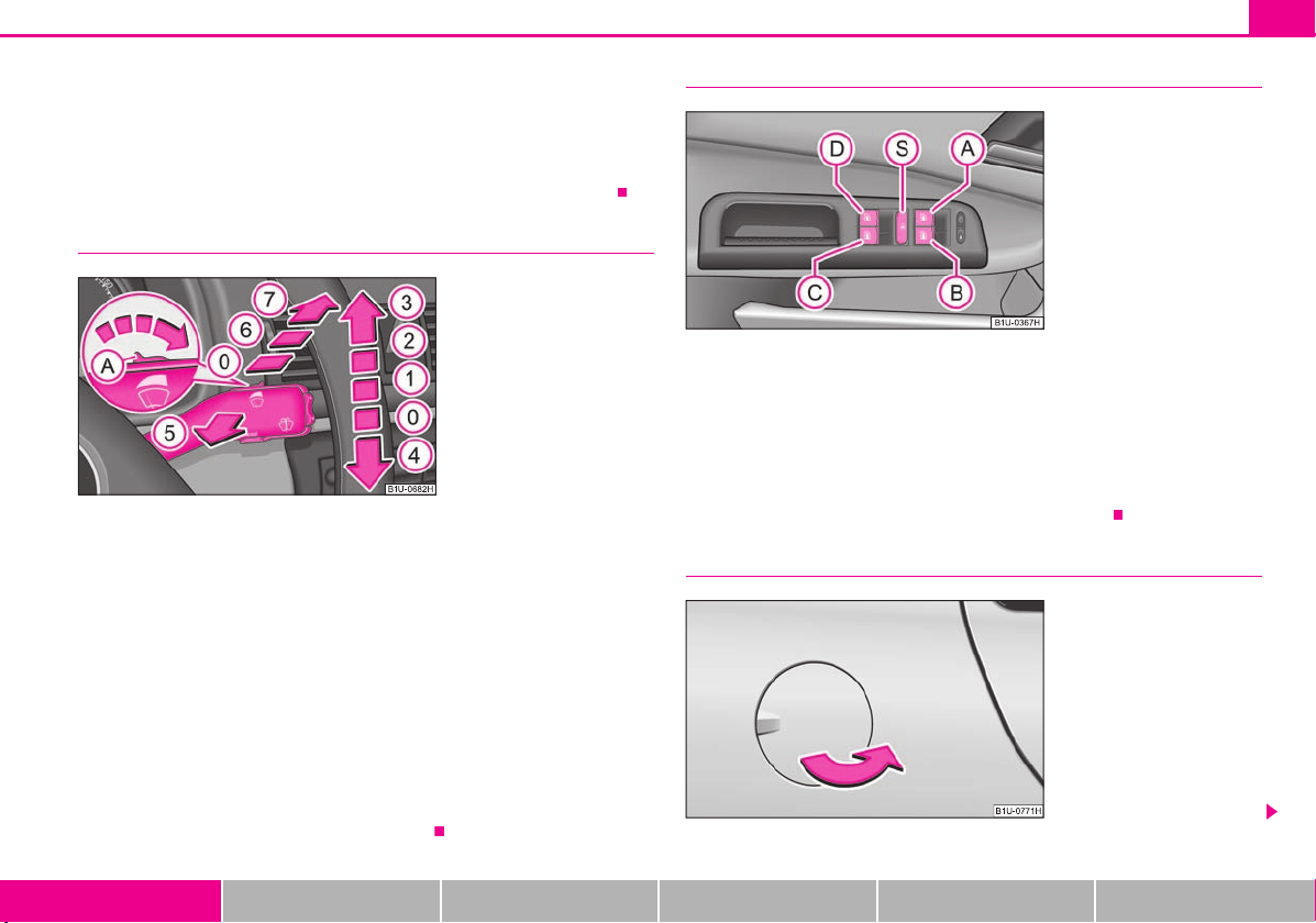
Fig. 10 Windscreen wiper lever
AAA0A1A2A3A4A
5A6A7
Fig. 11 Buttons on the driver's
door
AAABACADA
S
Fig. 12 Right rear side of the
vehicle: Fuel filler flap
Turn signal light right
Turn signal light left
Switching over between low beam and main beam lights
Headlight flasher
Further information page 49, “The turn signal and main beam lever ”.
Windscreen wiper lever
Intermittent switch, sensitivity setting rain sensor*
Wipers off
Intermittent wipe
Slow wipe
Fast wipe
one time wipe
Automatic wipe/wash
Rear window wiper*
Intermittent wipe - every 6 seconds
Automatic wipe/wash
Further information page 52, “Windshield wiper”.
Power windows*
Button for the power window in the driver's door
Button for the power window in the front passenger's door
Button for the power window at the rear right door
Button for the power window at the rear left door
Safety switch
Further information page 41, “Buttons on the driver's door”.
Refuelling
Using the system Safety Driving Tips General Maintenance Breakdown assistance Technical Data
Page 15
Quick Reference Guide14
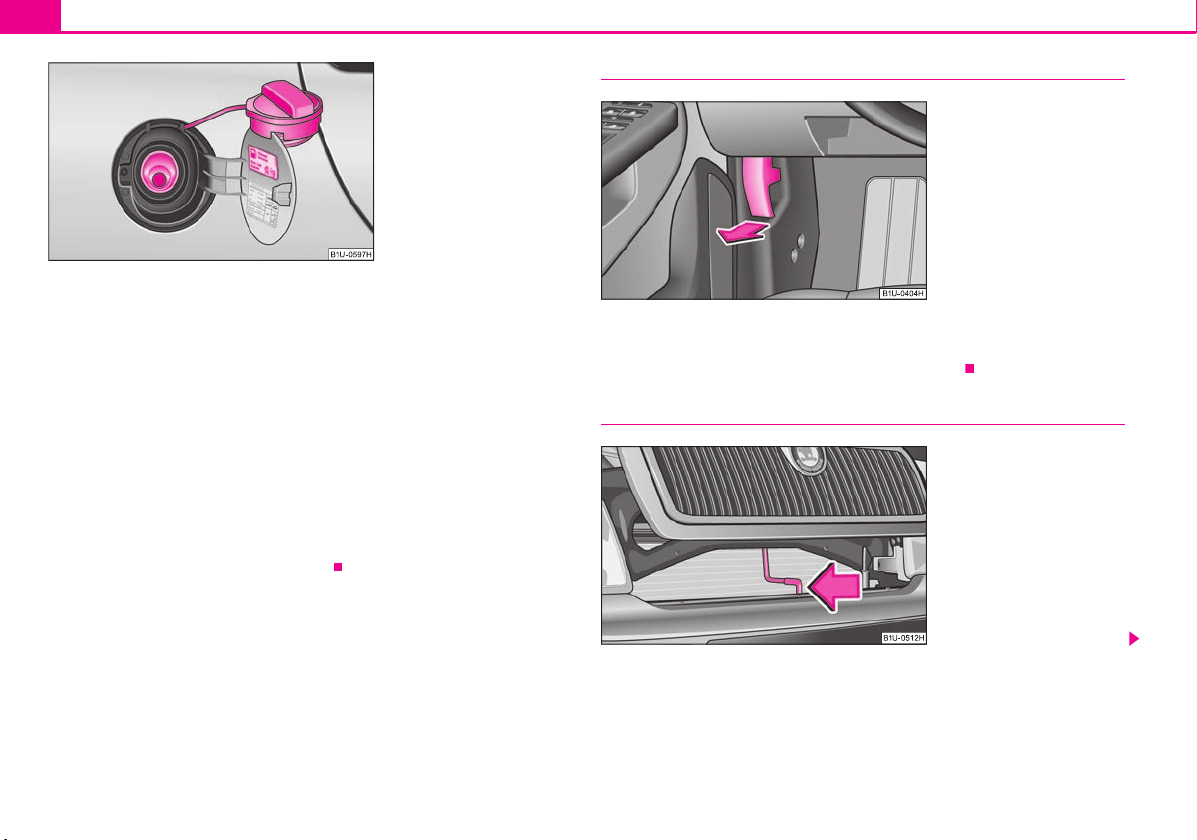
Fig. 13 Fuel filler flap with cap
unscrewed
Fig. 14 Bonnet release lever
Fig. 15 Radiator grille: Locking
lever
Opening the fuel filler cap
– Open the fuel filler flap with the hand.
– Unlock the fuel filler cap on the fuel filler tube to the left using the vehicle key.
– Unscrew the fuel filler cap anti-clockwise and place the fuel filler cap from above
on the fuel filler flap fig. 13.
Closing fuel filler cap
– Screw on the cap by turning it to the right until it is heard to lock.
– Lock the fuel filler cap on the fuel filler tube by turning the vehicle key to the right
and withdraw the key.
– Press the fuel tank flap closed.
Further information page 145, “Refuelling”.
Bonnet remote release
– Pull the unlocking lever below the dash panel on the driver's side fig. 14.
Further information page 147, “Bonnet remote release”.
Opening the bonnet
Page 16
– Grip with the hand under the radiator grille and lift up the bonnet.
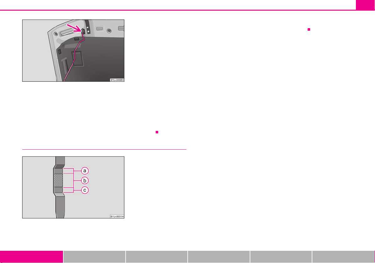
Fig. 16 Securing the bonnet with
the bonnet support
Fig. 17 Dipstick
AaAbA
c
– Press the locking lever in direction of arrow page 14, fig. 15 and lift up the
bonnet.
– Take the bonnet support out of its holder and set it in the opening designed for it
fig. 16.
Further information page 147, “Opening and closing the bonnet.”.
Inspecting the engine oil level
Quick Reference Guide 15
Engine oil must be refilled.
Further information page 150, “Check engine oil level”.
Engine oil must not be refilled.
Engine oil can be refilled.
Using the system Safety Driving Tips General Maintenance Breakdown assistance Technical Data
Page 17
Instruments and warning lights16
For the sake of the environment
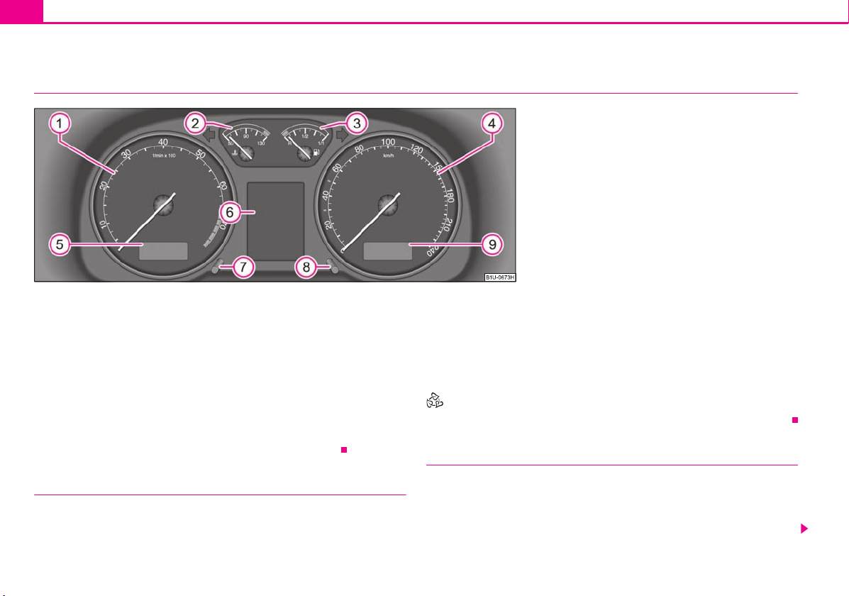
Fig. 18 Instrument cluster
A
1A2
A
3
A
4A5
A
6
A
7A8
A9A1A
2
Instruments and warning lights
Overview of the instrument cluster
Engine revolutions counter page 16
Coolant temperature gauge page 16
Fuel gauge page 17
Speedometer page 17
Digital clock, Multi-functional indicator* page 19
Information display* page 22
Clock-set button page 19
Reset button page 17
Odometer and trip counter, service interval display page 18
When the lights are switched on, the instrument cluster is illuminated.
Engine revolutions counter
The start of the red zone in the revolutions counter fig. 18 indicates the
maximum permissible engine speed for all gears for an engine which has been run in
and operating at a normal temperature. Before reaching this zone shift up into the next
higher gear.
One should shift to a lower gear at the latest when the engine is no longer running
“smoothly”.
Avoid high engine speeds when running-in the vehicle page 128.
Shifting up early helps you save fuel and reduce the operating noise of your vehicle.
Coolant temperature gauge
The coolant temperature gauge fig. 18 operates only when the ignition is
switched on.
In order to avoid any damage to the engine, please pay attention to the following notes
regarding the temperature ranges:
Page 18
Cold range
WARNING
Caution
Caution
Note
A
3
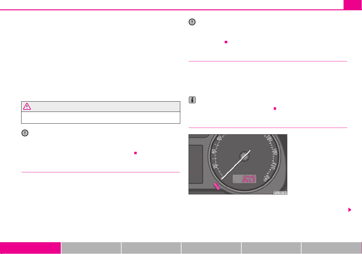
Fig. 19 Instrument cluster:
Counter for distance driven
If the pointer is in the left-hand area of the scale it means that the engine has not yet
reached its operating temperature. Avoid running at high engine speeds, at full throttle
and at severe engine loads.
The operating range
The engine has reached its operating temperature as soon as the pointer moves into
the mid-range of the scale. The pointer may also move further to the right at high
engine loads and high outside temperatures. This is not critical provided the warning
symbol
in the instrument cluster does not flash.
If the symbol in the instrument cluster flashes it means that either the coolant
temperature is too high or the coolant level is too low. Observe the guidelines
page 28, “Coolant temperature/coolant level ”.
Pay attention to the warning notes page 148, “Working in the engine
compartment” before opening the bonnet and inspecting the coolant level.
Additional headlights and other attached components in front of the fresh air inlet
impair the cooling efficiency of the coolant. There is then a risk of the engine overheating at high outside temperatures and high engine loads!
Fuel gauge
The fuel gauge page 16, fig. 18 only operates when the ignition is switched on.
The fuel tank has a capacity of about 55 litres. The warning symbol in the instrument
cluster lights up when the pointer reaches the reserve marking. There are now about 7
litres of fuel remaining in the tank. This symbol is a reminder for you, that you must
refue l.
The following will be displayed in the information display*:
PLEASE REFUEL
A peep sounds as an additional warning signal.
Instruments and warning lights 17
Never run the fuel tank completely empty! An irregular fuel supply can result in poor
ignition or misfiring. Unburnt fuel may get into the exhaust system and damage the
catalytic converter.
Speedometer
Warning against excessive speeds*
An acoustic warning signal will sound when the vehicle speed exceeds 120 kilometres
per hour. The acoustic warning signal will switch off again when the vehicle speed goes
below this speed limit.
This function is only valid for some countries.
Counter for distance driven
The distance which you have driven with your vehicle is shown in kilometres (km). On
certain model versions, the readout is shown in “miles”.
Using the system Safety Driving Tips General Maintenance Breakdown assistance Technical Data
Page 19
Instruments and warning lights18
WARNING
Fig. 20 Service Interval Display:
Note
A
8
Bottom (trip) counter for distance driven
The bottom counter indicates the distance which you have driven since it was last reset
- in steps of 100 m or 1/10 of a mile. The bottom counter can be reset by pressing the
reset button of the trip counter page 17, fig. 19.
Top counter for distance driven
The top counter indicates the total distance driven in kilometres or miles which the
vehicle has been driven.
Fau lt dis play
dEF appears permanently in the trip counter display for distance driven if there is a
fault in the instrument cluster. Have the fault rectified as soon as possible by a
specialist workshop.
Never seek to adjust the trip counter for distance driven while driving for safety
reasons !
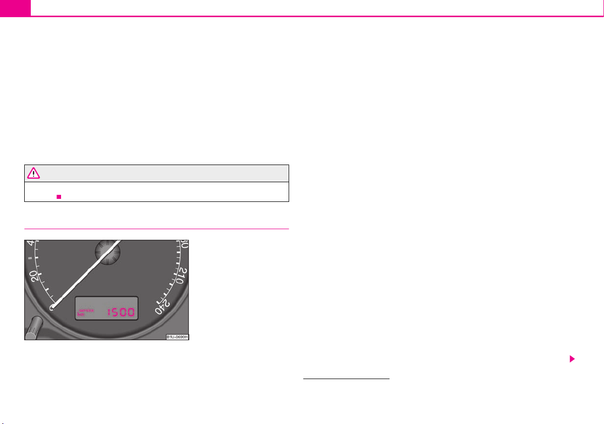
Service Interval Display
Depending on the equipment installed in the vehicle, the text can differ slightly on the
display.
Service Interval Display
If the due date for the service is reached, it is displayed1):
in the display of the trip counter:
Service 1 500 km
in the information display:
SERVICE in 1500 km
The kilometre readout decreases in steps of 100°km.
If the due date for the service is reached, the following text appears as a flashing
display:
in the display of the trip counter:
Service
in the information display:
SERVICE NOW
The display disappears within 20 seconds after switching on the ignition. The trip
counter is also displayed after pressing the reset button for the trip counter (for more
than 0.5 second).
Resetting Service Interval Display
It is only possible to reset the Service Interval Display, if a service message or at least a
pre-warning is shown on the display of the instrument cluster.
We recommend having this resetting performed by a specialist garage.
The specialist garage:
resets the memory of the display after the appropriate inspection;
makes an entry in the Service schedule;
affix the sticker with the entry of the following service interval to the side of the
dash panel on the driver's side.
The service interval display can also be reset with the reset button as follows
page 16, fig. 18:
1)
On some vehicles, the service interval display service OIL or service INSP is shown.
Page 20
Instruments and warning lights 19
Caution
Note
WARNING
Note
A
7
Press the reset button with the ignition switched off and and hold it down.
Switch the ignition on, release the reset button. The text Service or SERVICE NOW
appears in the display.
Turn the button for setting the clock to the right - as a result of this the display is
reset .
We recommend that you do not reset the Service Interval Display yourself otherwise
this can result in the service interval display being incorrectly set, which may also result
in problems with operation of your vehicle.
Never reset the display between service intervals otherwise this may result in
incorrect readouts.
information is retained in the Service Interval Display also after the battery of the
vehicle is disconnected.
It is necessary to re-code the Service Interval Display if a new instrument cluster is
installed during repair work. This work is carried out by a specialist garage.
The data displayed is the same after resetting the display with flexible service inter-
vals (QG1) using the reset button as that for a vehicle with fixed service intervals (QG2).
We therefore recommend having the Service Interval Display reset only by a specialist
garage which is familiar with the procedure for resetting the display with a vehicle
system tester.
Please refer to the brochure Service schedule for extensive information about the
service intervals.
Digital clock
Setting minutes
– Turn the reset button to the right.
The clock should not be adjusted while driving for safety reasons but only when
the vehicle is stationary!
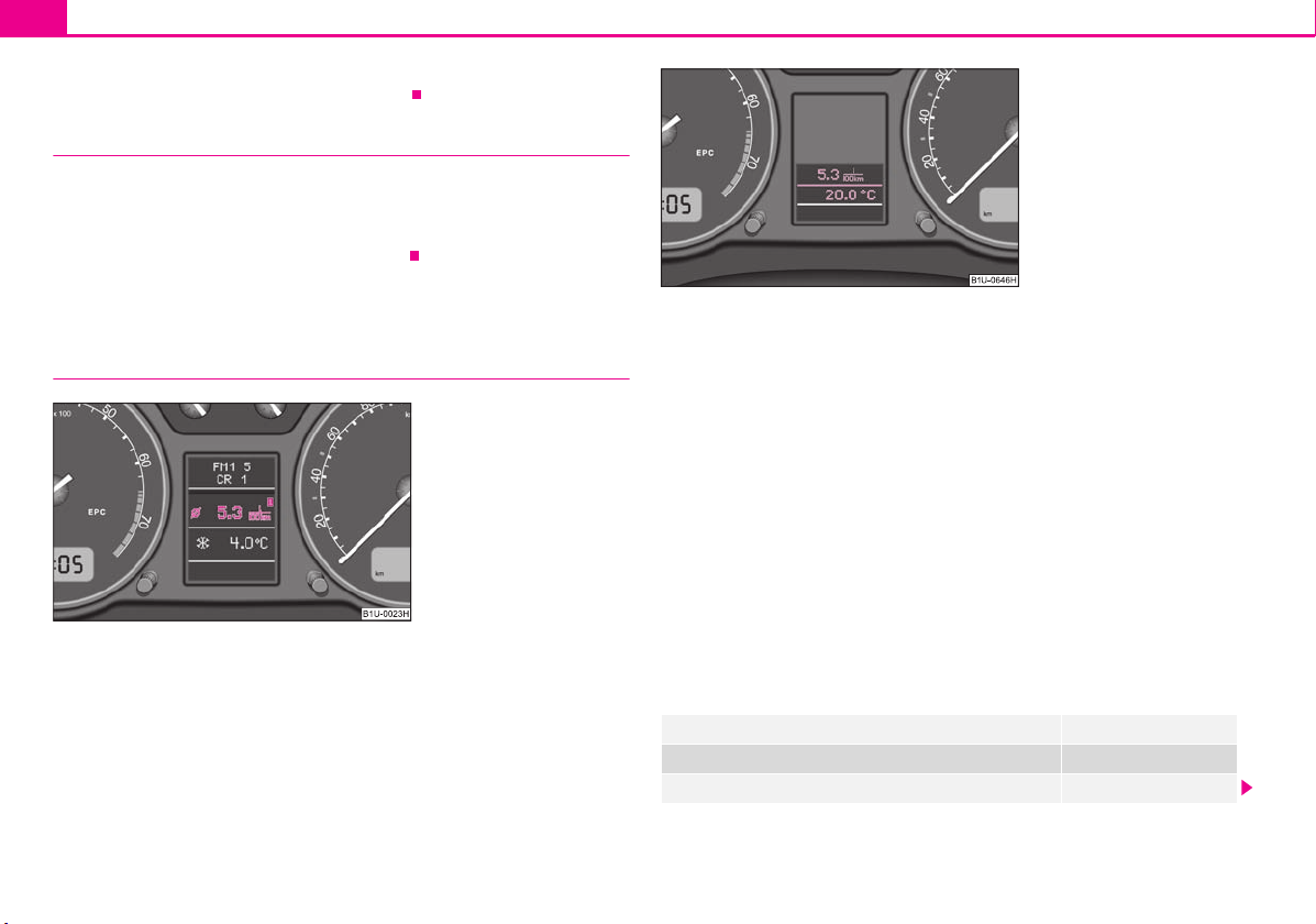
Multi-functional indicator (onboard computer)*
Introduction
The multi-functional indicator appears in the display of the revolutions counter or in
the information display depending on the equipment fitt ed to your vehicle page 22,
fig. 22.
The multi-functional indicator offers you a range of useful information.
The outside temperature page 20
Current fuel consumption page 21
Average fuel consumption page 21
Range page 21
Distance driven page 21
Average speed page 21
Driving time page 21
Time
A clock-set button is installed on the bottom left beside the speedometer for
adjusting the clock page 16, fig. 18.
Set hours
– Turn the reset button to the left.
Using the system Safety Driving Tips General Maintenance Breakdown assistance Technical Data
In certain national versions the displays appear in the Imperial system of measures.
Memory
The multi-functional indicator is equipped with two automatic memories.
Page 21
Instruments and warning lights20
Note
A
B
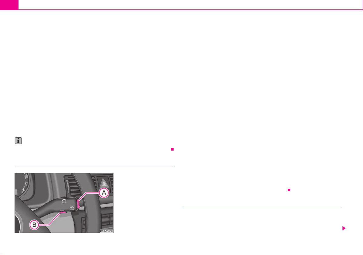
Fig. 21 Multi-functional indicator: Control elements
AAA
BAB
AAA
BABAA
The data of the single-trip memory (memory 1) is shown if a 1 appears in the display.
A 2 shown in the display means that data relates to the total distance memory
(memory 2).
Switching over the memory takes place with the button fig. 21.
Single-trip memory (memory 1)
The single-trip memory collates the driving information from the moment the ignition
is switched on until it is switched off. New data will also flow into the calculation of the
current driving information if the trip is continued within 2 hours after switching off
the ignition. The memory will be is automatically erased, on the other hand, if the trip
is interrupted for more than 2 hours.
Total-trip memory (memory 2)
The total distance driven memory gathers data from any number of individual journeys up to a total of 99 hours and 59 minutes driving or 9.999 kilometres driven. The
memory is deleted when either of these limits is reached and the calculation starts
from anew.
The total-trip memory will not, contrary to the single-trip memory, be deleted after a
period of interruption of driving of 2 hours.
All information in the memory is erased if the battery of the vehicle is disconnected.
Using the system
The rocker switch and the button are located on the windshield wiper lever
fig. 21.
Selecting the memory
– Repeated short-term pressing of the button allows to select the desired
memory.
Selecting the functions
– Press the rocker switch up or down. This will cause the individual functions of
the multi-functional indicator to appear in the display one after the other.
Setting function to zero
– Select the memory you want.
– Press button for more than 1 second.
The following readouts of the selected memory will be set to zero by button :
average fuel consumption,
distance driven,
average speed,
Driving time.
You can only operate the multi-functional indicator when the ignition is switched on.
After the ignition is switched on, the function displayed is the one which you last
selected before switching off the ignition.
If the outside temperature drops below +4 °C, the outside temperature indicator with
a snow flake symbol appears. The symbol warns the driver of the possible danger of
ice on the road. After the rocker switch is pressed, the function displays the one
which you last selected before switching off the ignition.
Outside temperature
The outside temperature appears in the display when the ignition is switched on.
The correct outside temperature will be indicated with a delay of 5 minutes. If the
vehicle is stationary (or driven at a very low speed) the temperature indicated may be
Page 22
Instruments and warning lights 21
WARNING
Note
A
BABAB
A
B
slightly higher than the actual outside temperature because of heat radiated by the
engine.
If the outside temperature drops below +4°C, a snow flake symbol (warning signal for
ice on the road) appears behind the temperature indicator and a warning signal
sounds.
Do not only rely upon the information given on the outside temperature
display that there is no ice on the road. Please note that black ice may also be
present on the road surface even at temperatures around +4°C - warning, drive
with care!
Current consumption
The current fuel consumption level is shown in the display in litres/100 km. This informat ion c an hel p you t o ada pt you r sty le of driving to the fuel consumption you wish to
achieve.
The display appears in litres/hour if the vehicle is stationary or driving at a low speed.
Average fuel consumption
The average fuel consumption since the memory was last erased is shown in the
display in litres/100 km page 19. This information can help you to adapt your style
of driving to the fuel consumption you wish to achieve.
If you wish to determine the average fuel consumption over a certain period of time
you must first erase the memory at the start of the new measurement using the button
page 20, fig. 21. A zero appears in the display for the first 300 m you drive after
erasing the memory.
The indicated value will be updated every 5 seconds while you are driving.
Range
The estimated range in kilometres is shown on the display. It indicates the distance you
can still drive with your vehicle based on the present level of fuel in the tank for the
same style of driving. The readout is shown in steps of 10 km.
The fuel consumption for the last 50 km is taken as a basis for calculating the range. If
you drive in a more economical manner from this moment on, the range will be
increased accordingly.
You first drive 50 km if the readout is reset (after disconnecting the battery) before a
new readout for the range is displayed.
Distance driven
The distance driven since the memory was last erased appears in the display
page 19. If you wish to calculate the distance driven from a particular time of day
you must first erase the memory at this moment in time by pressing the button
page 20, fig. 21.
The maximum distance indicated in both memories is 9 999 km. The indicator is set
back to null if this period is exceeded.
Average speed
The average speed since the memory was last erased is shown in the display in
km/hour page 19. If you wish to determine the average speed over a cer tain period
of time you must first erase the memory at the start of the new measurement using the
button page 20, fig. 21.
A zero appears in the display for the first 300 m you drive after erasing the memory.
The indicated value will be updated every 5 seconds while you are driving.
Driving time
The amount of fuel consumed will not be indicated.
Using the system Safety Driving Tips General Maintenance Breakdown assistance Technical Data
The driving time which has elapsed since the memory was last erased, appears in the
display page 19. If you wish to calculate the driving time from a particular time of
day you must first erase the memory at this moment in time by pressing the button
page 20, fig. 21.
Page 23
Instruments and warning lights22
Fig. 22 Instrument cluster: large
information display
Fig. 23 Instrument cluster: small
information display
The maximum distance indicated in both memories is 99 hours and 59 minutes. The
indicator is set back to null if this period is exceeded.
Warning against excessive speeds*
An acoustic warning signal will sound when the vehicle speed exceeds 120 kilometres
per hour. The acoustic warning signal will switch off again when the vehicle speed goes
below this speed limit.
This function is only valid for some export countries.
Information display*
Introduction
The information display provides you with information in a convenient way
concerning the current operating state of your vehicle. The information system also
provides you with data (depending on the equipment installed in the vehicle) relating
to the radio and multi-functional indicator.
Certain functions and operating conditions are always being checked on the vehicle
when the ignition is switched on and also while driving.
Functional faults, if required repair work and other information are indicated by red
symbols and yellow symbols.
Lighting up of these symbols is combined with an acoustic warning signal.
Information and texts giving warnings are also shown in the display page 25.
The display of text is possible in the following languages:
Czech, English, German, French, Italian, Spanish, Portuguese.
The desired language can be set by a specialist garage.
The following information can be shown in the display (depending on the equipment
installed on the vehicle):
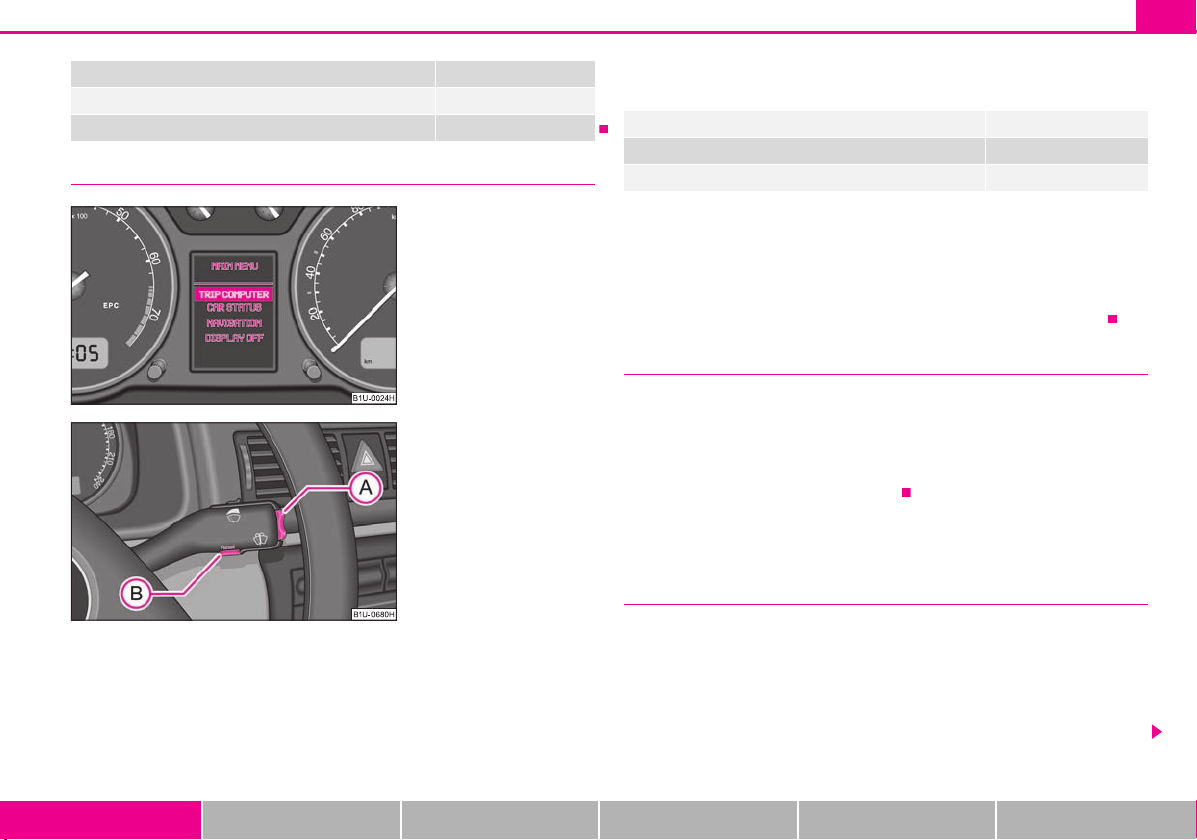
Menu page 23
Door and boot lid warning page 23
Displays of the multi-functional indicator page 16
Page 24
Instruments and warning lights 23
Fig. 24 Information display:
Menu
Fig. 25 Information display:
Control elements
A
AAA
A
B
A
A
A
A
Warning symbols or warning lights page 25
Displays of the Service Interval Display page 18
Displays of the radio
Menu
– You can activate the menu by pressing the rocker switch fig. 25 for more
than 1 second.
– You can select individual menu points by means of the rocker switch . The
selected information is displayed after pressing the button for a short time or
after releasing the rocker switch (after about 4 seconds).
You can select the following information (depending on the equipment installed on
the vehicle):
TRIP COMPUTER (AUTO COMPUTER) page 19
CAR STATUS page 23
DISPLAY OFF
After selecting the menu point DISPLAY OFF the display is switched off. Press the
rocker switch for more than 1 second to switch the display on again.
The Information CAR STATUSflashes in the menu if there is something which is not in
proper order on the vehicle (e.g. warning of a low fuel level). The first warning will be
displayed after switching over to CAR STATUS. You can then display other operating
conditions afterwards using the switch-over function (such as water level low).
Door and boot lid warning
The door and boot lid warning lights up if at least one door or the boot lid is not closed.
The symbol displays the respective opened door and boot lid.
The symbol goes out as soon as the doors and the boot lid are completely closed.
As an additional warning signal, a 3 time peep sounds if the car is driven at a speed of
more than 6km/hour and if the door is open.
Auto Check Control
Car state
The Auto Check Control carries out a check of certain functions and vehicle components. The check is performed constantly when the ignition is switched on, both when
the vehicle is stationary, as well as when driving.
Operational faults, urgent repairs, service work or other information appear in the
display of the instrument cluster. The displays are shown with a red or yellow light
symbol depending on the priority of the message.
Using the system Safety Driving Tips General Maintenance Breakdown assistance Technical Data
Page 25

Instruments and warning lights24
AAA
A
The red symbols indicate danger (priority 1) while the yellow symbols indicate a
warning (priortity 2). Information for the driver may also appear in addition to the
symbols page 25.
Investigate the displayed faults as soon as possible. If several operational faults exist at
the same time, the symbols will appear one after the other and are each visible for
about 2 seconds.
The error messages are faded out after 10 seconds or by actuating the rocker switch
page 23, fig. 25 and are stored under the information CAR STATUS.
There is at least one error message to be read when the term CAR STATUS is flashing
in the menu. In the display STATUS 1/2 lights up, for example, if a number of error
messages are present. This display indicates that the first of a total of two error
messages should be displayed.
Actuate the rocker switch , to call up the individual error messages.
If a fault occurs, a warning signal will also sound in addition to the symbol and text in
the display:
Priority 1 - three warning signals
Priority 2 - one warning signal
Red symbols
A red symbol signals danger.
Proceed as follows if a red symbol is displayed:
– Stop the vehicle.
– Switch the engine off.
– Check the functions indicated.
– Obtain professional assistance.
Meaning of the red symbols:
Faults in the brake surface page 31
Coolant level too low/coolant temperature too
high
Three successive warning signals will sound if a red symbol appears. The symbol
continues flashing until the fault is rectified.
If several operational faults of priority 1 exist, the symbols appear one after the other
and are each illuminated for about 2 seconds.
Engine oil pressure too low page 29
page 28
Yellow symbols
A yellow symbol signals a warning.
The meaning of the yellow symbols:
Fuel level low page 29
Check engine oil level, engine oil sensor faulty page 29
Brake pad worn page 29
Washer fluid level low page 29
faulty bulb page 27
One warning signal will sound if a yellow symbol appears.
If several operational faults of priority 2 exist, the symbols appear one after the other
and are each illuminated for about 2 seconds.
Check the relevant function as soon as possible.
Page 26
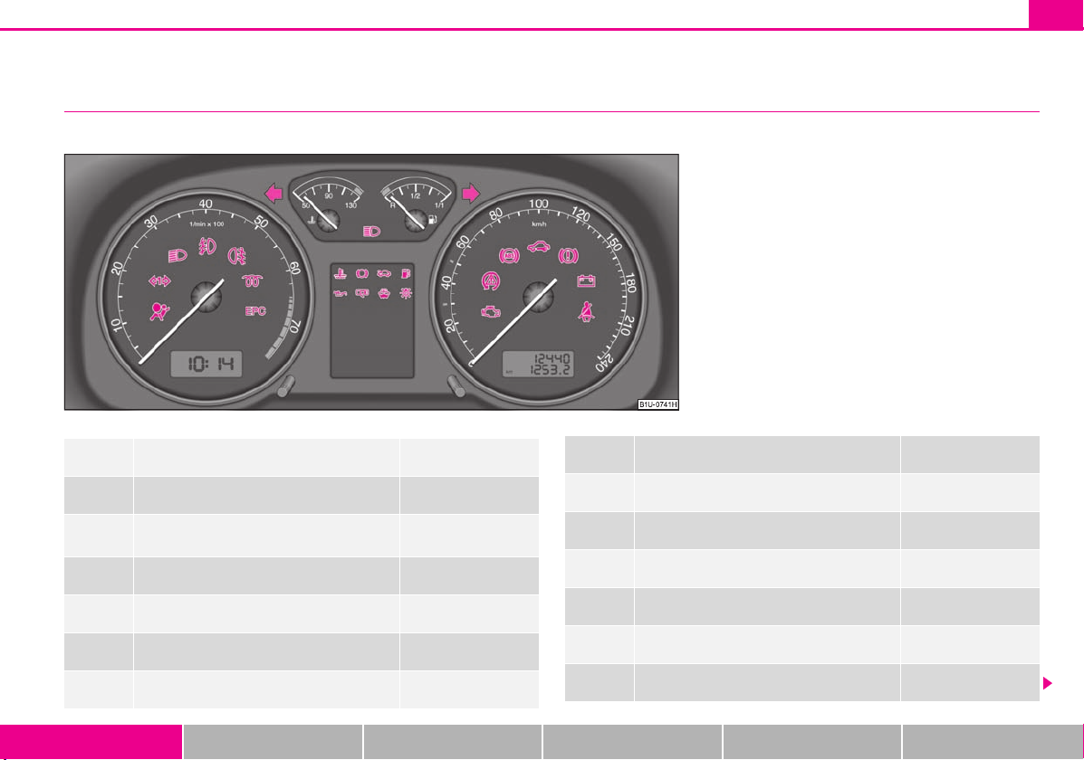
Warning lights
Fig. 26 Instrument cluster with warning lights
Overview
The warning lights indicate certain functions or faults.
Instruments and warning lights 25
Turn signal lights (to the left) page 26
Turn signal lights (to the right) page 26
Turn signal system for vehicles towing a
trailer*
Main beam light page 26
Low beam light page 26
Fog lights* page 27
Rear fog light page 27
Using the system Safety Driving Tips General Maintenance Breakdown assistance Technical Data
page 26
Electronic immobiliser page 27
Bulbs* page 27
Control system for exhaust page 27
EPC fault light* (petrol engine) page 27
Glow plug system (diesel engine) page 27
Airbag system* page 28
Coolant temperature/coolant level page 28
Page 27
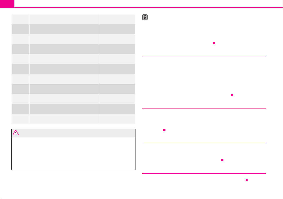
Instruments and warning lights26
WARNING
Note
Brake pad wear* page 29
Fuel reserve page 29
Engine oil page 29
Open door* page 30
Fluid level in windshield washer system* page 29
Antilock brake system (ABS)* page 30
Traction control system (TCS)* page 31
Electronic stability programme (ESP)* page 31
Dynamo page 31
Brake system page 31
Seat belt warning light* page 32
Arrangement of the indicator lig hts depends on the model and model version. The
symbols shown in the following functional description are to be found as indicator
lights in the instrument cluster.
Operational faults are shown in the instrument cluster as red symbols (priority 1 -
danger) or yellow symbols (priority 2 - warning).
Turn signal system
Either the left or right indicator light flashes depending on the position of the turn
signal lever.
The indicator light flashes at twice its normal rate if a turn signal light fails. This does
not apply when towing a trailer.
Switching off the hazard warning light system is switched on will cause all of the turn
signal lights as well as both indicator lights to flash.
Further information about the turn signal system page 49.
Turn signal system for vehicles towing a trailer *
The warning light flashes together with the other turn signal lights only if the vehicle
is towing a trailer.
The indicator light does not flash if a turn signal light on the trailer or on the vehicle is
not operating.
If you do not pay attention to the warning lights coming on and the corre-
sponding descriptions and warning notes, this may result in severe body injuries or major vehicle damage.
The engine compartment of your car is a hazardous area. There is a risk of
injuries, scalding, accidents and fire when working in the engine compartment,
e.g. inspecting and replenishing oil and other fluids. It is also essential to
observe all warnings page 148.
Main beam
The indicator light comes on when the main beam is selected or also when the
headlight flasher is operated.
Further information about the main beam page 49.
Low beam
The warning light comes on when low beam is selected page 46.
Page 28

Instruments and warning lights 27
Fog lights *
The warning light comes on when the fog lights are operating.
Rear fog light
The warning light comes on when the rear fog lights are operating page 47.
Electronic immobiliser
Data is compared between the ignition key and the control unit when switching on the
ignition. The indicator light will light up for a few seconds when ignition key
authorisation is confirmed.
The warning light will start flashing continuously if a non-authorised ignition key (for
example the wrong ignition key) has been used. The engine cannot be started
page 34.
It is only possible to start the engine of the vehicle with a Genuine Škoda key with the
matching code.
The following text will be displayed in the information display*:
IMMOBIL. ACTIVATED
Bulbs
The warning light comes on if a bulb is faulty:
Brakes applied (brake light);
Switching on the lights (front low beam or rear parking lights).
A peep sounds as an additional warning signal.
Control system for exhaust
The warning light comes on after the ignition has been switched on.
If the warning light does not go out after starting the engine or it lights up or flashes
when driving, a fault exists in an exhaust relevant component. The engine manage-
ment system selects an emergency programme which enables you to drive to the
nearest specialist garage by adopting a gentle style of driving.
The following text will be displayed in the information display*:
EMISSIONS WORKSHOP!
EPC fault light (petrol engine)
The (Electronic Power Control) warning light comes on for a few seconds when the
ignition is switched on.
If the warning light does not go out or lights up after starting the engine, a fault
exists in the engine control. The engine management system selects an emergency
programme which enables you to drive to the nearest specialist garage by adopting a
gentle style of driving.
The following text will be displayed in the information display*:
ENGINE WORKSHOP!
Glow plug system (diesel engine)
The warning light lights up for a cold engine when switching on the ignition (preheat position) 2 page 87. Star t the engine just as soon as the indicator light goes out.
The glow plug indicator light will come on for about 1 second if the engine is at a
normal operating temperature or if the outside temperature is above +5°C. This
means that you can start the engine right away.
There is a fault in the glow plug system if the warning light does not come on at
all or lights up continuously. Contact a specialist g arage as soon as possible to obtain
assistance.
If the warning light begins to flash while driving, a fault exists in the eng ine control.
The engine management system selects an emergency programme which enables you
to drive to the nearest specialist garage by adopting a gentle style of driving.
The following text will be displayed in the information display*:
ENGINE WORKSHOP!
Using the system Safety Driving Tips General Maintenance Breakdown assistance Technical Data
Page 29

Instruments and warning lights28
WARNING
Note
WARNING
Airbag system
Monitoring the airbag system
The warning light comes on for a few seconds when the ignition is switched on.
There is a fault in the system if the warning light does not go out or comes on or flashes
while driving . This also applies if the warning light does not come on when the
ignition is switched on.
The following text will be displayed in the information display*:
AIRBAG FAULT
The functionality of the airbag system is also monitored electronically when one airbag
has been switched off.
Front airbag or side passenger airbag deactivated using the diagnostic equipment:
The warning light lights up for 3 seconds after switching on the ignition and then
flashes again for 12 seconds.
The following situation applies if the airbag has been switched off using the
switch for the airbag* in the storage compartment:
The warning light comes on for 3 seconds after the ignition has been switched
on.
The deactivation of the airbag is indicated by the lighting up of the indicator light
in the interior lighting page 113.
Have the airbag system checked immediately by a specialist garage if a fault
exists. Otherwise, there is a risk of the airbag not being activated in the event of
an accident.
Further information about switching off airbags page 113.
Coolant temperature/coolant level
The warning light comes on for a few seconds 2) when the ignition is switched on.
The coolant temperature is too high or the coolant level too low if the warning light
does not go out or flashes while driving.
3 peeps sound as an additional warning signal.
In this case stop and switch the engine off and check the coolant level; top up the
coolant as necessary.
Do not continue your journey if for some reason it is not possible under the conditions prevailing to top up with coolant. Keep the engine switched off and obtain
professional assistance from a specialist garage, otherwise it could lead to severe
engine damage.
If the coolant is within the specified range, the increased temperature may be caused
by an operating problem at the coolant fan. Check the fuse for the coolant fan, replace
it if necessary page 178, “Fuse assignment in engine compartment - version 1” or
page 179, “Fuse assignment in engine compartment - version 2”.
Do not continue driving if the warning light does not go off al though the fluid is at the
correct level and also the fuse of the fan is in proper order. Contact a specialist garage
to obtain assistance.
Please refer to the following guidelines page 152, “Cooling system”.
The following text will be displayed in the information display*:
STOP CHECK COOLANT SERVICE MANUAL
If you must stop for technical reasons, then park the vehicle at a safe
distance from the traffic and switch off the engine and switch on the hazard
warning light system page 48.
Take care when opening the coolant expansion bottle. If the engine is hot,
the cooling system is pressurized - risk of scalding! It is best to allow the engine
to cool down before removing the cap.
2)
The warning light on vehicles fitted with information display does not come on after switching
the ignition on, but only if the coolant temperature is too high or the coolant level is too low.
Page 30
Note
Engine oil
WARNING (continued )
Instruments and warning lights 29
Do not touch the coolant fan The coolant fan may switch on automatically
even if the ignition is off.
Thickness of the brake pads*
The warning light comes on for a few seconds when the ignition is switched on.
If the warning light comes on, contact a specialist garage immediately and have the
brake pads on all of the wheels inspected.
A peep sounds as an additional warning signal.
The following text will be displayed in the information display*:
CHECK BRAKE PADS
Windshield washer fluid level*
The warning light comes on when the ignition is switched on if there is insufficient
fluid in the windshield washer system. Top up with liquid page 159.
A peep sounds as an additional warning signal.
The following text will be displayed in the information display*:
TOP U P WASH FLUID
Fuel reserve
The warning light comes on, if the fuel level is still below 7 litres.
A peep sounds as an additional warning signal.
The following text will be displayed in the information display*:
PLEASE REFUEL
The warning light lights up red (low oil pressure)
The warning light comes on for a few seconds when the ignition is switched on 3).
Stop the vehicle and switch the engine off if the warning light does not go off within
a few seconds after switching on the ignition or flashes while driving. Check the oil
level and top up with oil as necessary page 151.
3 peeps sound as an additional warning signal.
Do not continue your journey if for some reason it is not possible under the conditions prevailing to top up with oil. Keep the engine switched off and obtain profes-
sional assistance from a specialist garage, otherwise it could lead to severe engine
damage.
Do not drive any further if the warning light remains on even if the oil is at the correct
level. Do not run the engine not at idling speed either. Contact the nearest specialist
garage to obtain professional assistance.
The following text will be displayed in the information display*:
STOP! OIL PRESS. STOP MOTOR! SERVICE MANUAL
The warning light lights up yellow* (oil quantity too low)
If the warning light lights up yellow, there is not the correct quantity of oil in the engine.
Check as soon as possible the oil level or top up page 151 with engine oil.
A peep sounds as an additional warning signal.
The following text will be displayed in the information display*:
CHECK OIL LEVEL
When opening the bonnet, the warning light goes out. If no engine oil has been replenished, the warning light will come on again after driving about 100 km.
The warning light flashes yellow* (engine oil level sensor faulty)
A fault on the engine oil level sensor is indicated additionally by an audible signal and
the warning light coming on several times after the ignition has been switched on.
The Text in the information display* goes out only after refuelling and driving a short
distance.
Using the system Safety Driving Tips General Maintenance Breakdown assistance Technical Data
3)
The warning light on vehicles fitted with information display does not come on after switching the ignition on, but only if a fault exists or the engine oil level is too low.
Page 31

Instruments and warning lights30
WARNING
WARNING
In this case have the engine inspected without delay by a specialist garage.
The following text will be displayed in the information display*:
OIL SENSOR WORKSHOP!
If you must stop for technical reasons, then park the vehicle at a safe
distance from the traffic and switch off the engine and switch on the hazard
warning light system page 48.
The red oil pressure light is not an oil level indicator! One should there-
fore check the oil level at regular intervals, preferably after every refueling
stop.
Open door*
The warning light comes on, if one or several doors are opened.
The warning light on vehicles fitted with information display comes on when switching
the ignition off. If a door or the boot lid is opened.
The warning light on vehicles fitted with information display goes out after switching
the ignition off.
Antilock brake system (ABS)*
The warning light shows the functionality of the ABS and the Electronic Differential
Lock (EDL)*.
The warning light comes on for a few seconds after the ignition has been switched on
or when starting the engine. The warning light goes out after an automatic check
sequence has been completed.
A fault in the ABS
The system is not functioning properly if the ABS warning light does not go out
within a few seconds after switching on the ignition, does not light up at all or lights up
while driving. The vehicle will only be braked by the normal brake system. Visit a
specialist garage as quickly as possible and adjust your style of driving to take account
of the fault in the meantime since you will not know the extent of the fault and in how
far the effect of the antilock brakes is affected.
Further information about ABS page 126, “Antilock brake system (ABS)*”.
A fault in the entire brake system
If the ABS warning light comes on together with the brake system warning light
(handbrake must be released), there is a fault not only in the ABS but also in another
part of the brake system .
Electronic Differential Lock (EDL)*
The EDL is a part of the ABS. A fault in the EDL is indicated by the lighting up of the ABS
warning light in the instrument cluster. Have the vehicle inspected immediately by
your nearest specialist garage.
Models fitted with ESP are equipped with electronic differential lock (EDL).
If a significant fault occurs in the ABS system, a warning signal sounds additionally (3
peeps).
Further information on the EDL page 124.
If the brake system warning light comes on together with the ABS
warning light stop the vehicle immediately and check the brake fluid level in
the reservoir page 154, “Brake fluid”. If the fluid level has dropped below the
MIN marking, do not drive any further - risk of accident! Obtain professional
assistance.
Pay attention to the following instructions before checking the brake fluid
level and opening the bonnet page 148, “Working in the engine compartment”.
If the brake fluid is at the correct level, the ABS control function has failed.
The rear wheels may then block very rapidly when braking. In certain circumstances, this can result in the rear end of the car breaking away - risk of skidding! Drive carefully to the nearest specialist garage and have the fault
rectified.
Page 32

Traction control system (TCS)*
Note
Caution
The warning light comes on for a few seconds when the ignition is switched on.
The warning light flashes when a control cycle is activated while driving.
The warning light will come on and remains on if the TCS is switched off or if there is a
fault in the system.
The fact that the TCS system operates together with the ABS means that the TCS
warning light will also come on if the ABS system is not operating properly.
If the warning light comes on immediately after starting the engine, the TCS system
can be switched off for technical reasons. In this case, the TCS system can be switched
on again by switching the ignition on and off. If the warning light goes out, the TCS
system is fully functional again.
Further information about the TCS page 125, “Traction control system (TCS)”.
Electronic stability programme (ESP)*
The warning light comes on for a few seconds when the ignition is switched on.
Components of the ESP system also include the Traction Control System (TCS), the
Electronic Differential Lock (EDL) and the Antilock Brake System (ABS).
The warning light flashes when a control cycle is activated while driving.
The warning light will come on and remains on if the ESP is switched off or if there is a
fault in the system.
The fact that the ESP system operates together with the ABS and the EDL means that
the ESP warning light will also come on if the ABS system is not operating properly.
If the warning light comes on immediately after starting the engine, the ESP system
can be switched off for technical reasons. In this case, the ESP system can be switched
on again by switching the ignition on and off. If the warning light goes out, the ESP
system is fully functional again.
Further information on the ESP page 123, “Electronic stability programme (ESP)*”.
Instruments and warning lights 31
If the battery has been disconnected and reconnected, the warning light comes on
after switching on the ignition. The warning light must go out after driving a short
distance.
Alternator
The warning light comes on after the ignition has been switched on. It should go
out after the engine has started.
If the warning light does not go out after the engine has started, or comes on when
driving, drive to the nearest specialist garage. The vehicle battery will be discharged in
this case so switch off all non-essential electrical components.
A peep sounds as an additional warning signal.
If the warning light comes on when driving and in addition the warning light
(cooling system fault) also comes on in display, you must then stop the car immediately and switch the engine off - risk of engine damage!
Brake system
The warning light comes on for several seconds after the ignition is switched on.
If the warning light stays on when the ignition is switched on or comes on while
driving, there is a fault in the brake system. Visit the nearest specialist garage immediately and have the brake system inspected.
The following text will be displayed in the information display*:
STOP BRAKE FLUID SERVICE MANUAL
3 peeps sound as an additional warning signal.
One should get used to high pedal forces, long braking distances and long free play of
the brake pedal when driving to the next specialist garage.
For further information on the brake system page 125, “Brakes”.
Using the system Safety Driving Tips General Maintenance Breakdown assistance Technical Data
Page 33

Instruments and warning lights32
WARNING
Handbrake applied
The warning light also comes on if the handbrake is applied. An audible warning is
also given if you drive the vehicle for at least 3 seconds at a speed of more than 5 km/h.
The following text will be displayed in the information display*:
HANDBRAKE ON
Pay attention to the following instructions before checking the brake fluid
level and opening the bonnet page 148, “Working in the engine compartment”.
If the brake system warning light does not go out a few seconds after
switching on the ignition or comes on when driving, stop immediately and
check the brake fluid in the reservoir page 154, “Brake fluid”. If the fluid level
has dropped below the MIN marking, do not drive any further - risk of accident!
Obtain professional assistance.
Seat belt warning light*
The warning light comes on after the ignit ion is switched on as a reminder to fasten
the seat belt.
In the event that the driver is not restrained, a warning signal sounds for 6 seconds.
The following text will be displayed in the information display*:
FAS TEN SEAT BELT
Further information on the seat belts page 102, “Seat belts”.
Page 34

Unlocking and locking
WARNING
Caution
Note
Fig. 27 Set of keys without
remote control
Fig. 28 Remote control key
Unlocking and locking 33
Key
Two keys are provided with the vehicle. Depending on the equipment, your vehicle
can be equipped with keys without radio remote control fig. 27 or with radio
remote control* fig. 28.
Key r ing
A plastic tag fig. 27 is attached to one of the keys with the identification of the key.
This identification can be used to order replacement keys from specialist garages.
Carefully store the key ri ng on which there is the number, because a replacement key
can only be ordered with this number in case the key is lost or damaged. You should
also therefore hand over this key ring to the purchaser when selling the vehicle.
Always withdraw the key whenever you leave the vehicle - even if it is only
for a short time. This is particularly important if children are left in the vehicle.
The children might otherwise start the engine or operate electrical equipment
(e.g. power windows) - risk of injury!
Do not withdraw the ignition key from the ignition lock unti l the vehicle has
come to a stop. The steering lock might otherwise engage unintentionally - risk
of accident!
Each key contains electronic components; therefore protect them against mois-
ture and severe shocks.
Keep the groove of the keys absolutely clean as impurities (textile fibres, dust etc.)
have a negative effect on the proper operation of the locking cylinder and the ignition
lock.
Please approach a specialist garage if you lose a key since he can obtain a new one for
you.
Using the system Safety Driving Tips General Maintenance Breakdown assistance Technical Data
Page 35

Unlocking and locking34
For the sake of the environment
Note
Note
Fig. 29 Disconnect key with
radio remote con trol
Fig. 30 Cover of the transmitter
housing
ABA
AAB
Changing the battery of the radio remote control
Each remote control key contains a battery which is housed in the cover fig. 29
of the transmitter housing. We recommend having the battery of the key replaced by
a specialist garage. You should, however, proceed as follows if you wish to replace the
battery yourself:
– Fold open the key.
– Use a thin screwdriver to carefully lever off the front part of the key fig. 29
from the transmitter housing .
– Take off the cover of the transmitter housing fig. 30 in direction of arrow.
– Take the used battery out of the housing cover.
– Insert the new battery. Ensure that the “+” symbol on the battery is facing down-
wards. The correct polarity is also shown on the cover of the transmitter housing.
– Insert cover with battery in place at the rear of the transmitter housing and press
both parts together.
– Insert the transmitter housing into the front part of the key so that the two parts
lock into each other.
Dispose of a used battery in accordance with environmental regulations.
The replacement battery must have the same specification as the original battery.
If it is still not be possible to unlock or lock the vehicle with the remote control even
after replacing the battery this means that the system has to be synchronised
page 40.
Electronic immobiliser
The electronic immobiliser prevents the vehicle being operated by an
unauthorised person.
An electronic chip is integrated in the head of the key. The immobiliser is deactivated
with the aid of this chip when the key is inserted in the ignition lock. The electronic
immobiliser is automatically activated when you withdraw the ignition key from the
lock.
It is only possible to start the engine of your car with a Genuine Škoda key with the
matching code page 27.
Locking
Valid for vehicles without a central locking system:
Page 36

Unlocking and locking 35
Note
Fig. 31 Child safety locks on the
rear d oors
Locking from outside
The securing knob will move upwards or downwards in the door when unlocking or
locking.
Locking from inside
All closed vehicle doors are locked by pressing in the securing knobs from the inside.
The doors cannot be opened from the outside when the securing knobs have been
pressed in. The vehicle doors can be opened from the inside as follows:
the door is unlocked by actuating the door-opening lever;
The door opens upon actuating the door-opening lever again.
The opened door cannot be locked with the securing knob. This prevents the
possibility of forgetting the key in the locked vehicle.
The opened side doors at the rear and the front passenger door are locked by
pressing in the securing knob and slamming the door closed.
Please refer to the safety guidelines page 35.
Child safety lock
The child safety lock prevents the rear door from being opened from the
inside.
The rear doors are equipped with a child safety lock. You can switch the child safety
lock on and off using the vehicle key.
Switching child safety lock on
– Use the vehicle key to turn the slit in the rear door to the left in the direction of the
arrow fig. 31.
Switching child safety lock off
– Use the vehicle key to turn the slit to the right against the direction of the arrow.
So long as the child safety lock is switched on it is not possible to open the door from
the inside with the door opening lever. In this case the door can be opened only from
the outside.
Central locking system*
Description
Unlocking or locking the vehicle causes all d oors t o be un locke d or lo cked a t the s ame
time by the central locking system. The boot lid is unlocked when opening. It can be
opened by pressing the hand grip above the licence plate page 38, fig. 34.
Operation of the central locking system is possible:
from the outside using the vehicle key page 37,
using the button for the central locking system page 37,
by using the remote control page 39.
with the securing knobs in the doors page 37, fig. 33 - only for vehicles which
are not fitted with electrically operated power windows (only for locking).
Warning light and securing knobs in the doors
All the securing knobs move upwards when unlocking.
The driver door must be closed when locking. Other doors can also be closed after
locking.
Using the system Safety Driving Tips General Maintenance Breakdown assistance Technical Data
Page 37

Unlocking and locking36
WARNING
Note
WARNING
Note
All the securing knobs move downwards when locking. If this is not the case, the rele-
vant door must be opened once again and properly closed.
The warning light flashes in the driver door, next to the securing knob, to confirm that
the vehicle has been correctly locked. The warning light will not flash if the safe
securing system is deactivated page 36.
This is not the case, however, for vehicles with an anti-theft alarm system* since the
indicator light is showing that the system is active.
Convenience operation of the windows
One can open and close the electrically powered windows when unlocking and
locking the vehicle page 43, “Window convenience operation”.
Opening a single door*
This function makes it possible to only unlock the driver's door. The other doors
remain locked and are only unlocked when the command is repeated.
If you wish, you can have a specialist garage activate the function of the single door
opening mode.
Locking the doors prevents involuntary opening in an exceptional situation (an
accident). Locked doors prevent unwanted entry into the vehicle from outside,
for example at road crossings. Locked doors do, however, make it more difficult
for rescuers to get into the vehicle in an emergency - danger to life!
In the event of an accident in which the airbags are deployed, the locked doors are
automatically unlocked in order to enable rescuers to gain access to the vehicle.
Only the front doors can be unlocked and locked using the key if the central locking
system fails. You can lock or unlock manually the other doors and the boot lid.
Emergency locking of the door page 38.
After locking the vehicle via the central locking system, optically check if all the
doors have been locked - position of the securing knobs.
Safe securing
The central locking system is equipped with a safe securing system. Locking the
vehicle from the outside causes the door locks to be automatically blocked. It is not
possible to open the doors with the door handle either from the inside or from the
outside. This acts as an effective deterrent for attempts to break into your vehicle.
If you lock the vehicle with a key or a remote control key, you can deactivate the safe
securing system by locking two times within 2 seconds.
The warning light in the driver door will not flash if the safe securing system is deactivated.
This is not the case, however, for vehicles with an anti-theft alarm system* since the
indicator light is showing that the system is active.
The safe securing system is again activated the next time the vehicle is unlocked and
locked again.
The doors can be opened from the inside if the vehicle is locked and the safe securing
system is deactivated:
the door is unlocked by actuating the door-opening lever;
The door opens upon actuating the door-opening lever again.
If the vehicle is locked from the outside and the safe securing system is activated, there must not be any person and animals in the vehicle as it is then not
possible to open either a door or a window from the inside. The locked doors
make it more difficult for rescuers to get into the vehicle in an emergency hazard!
The anti-theft alarm system* is also activated with the deactivated safe securing
system when locking the vehicle. The interior monitor* is however not activated.
Page 38

Unlocking and locking 37
Note
Note
Fig. 32 Turning the key for
unlocking and locking the
vehicle
AAA
B
Fig. 33 Button for the central
locking system
A
1
Unlocking the vehicle using the key
– Turn the key in the locking cylinder of the driver's door to the left in the unlock
position fig. 32.
– Pull on the door handle and open the door.
All the doors are unlocked.
The boot lid is then unlocked.
The switched on interior lights come on over the door contact.
The safe securing system is deactivated.
The windows open provided the key is held* in the unlock position. On vehicles
fitted with anti-theft alarm system the window operation is only possible 45 seconds
after deactivation of the warning system.
The indicator light in the driver's door stops flashing if the vehicle is not fitted with
an anti-theft alarm system* page 40.
Locking the vehicle with the key
– Turn the key in the locking cylinder of the driver's door to the right in the lock posi-
tion fig. 32.
All the doors and the boot lid are locked.
The switched on interior lights will switch off over the door contact.
The windows and the electric sliding/tilting roof* close provided the key is held in
the lock position.
The safe securing system is activated immediately.
The indicator light in the driver door begins flashing.
The opened driver door cannot be locked. It must be locked separately after closing
it.
Button for the central locking system
If the vehicle is equipped with an anti-theft alarm system*, you must insert the key into
the ignition lock and switch the ignition on within 15 seconds after unlocking the door
in order to deactivate the anti-theft alarm system. The alarm will be triggered if you
do not switch on the ignition within 15 seconds.
Using the system Safety Driving Tips General Maintenance Breakdown assistance Technical Data
If the vehicle is not locked from outside, you can unlock and lock the vehicle with the
button in the driver door.
Locking all doors and the boot lid
– Press button fig. 33. The symbol in the button comes on.
Page 39

Unlocking and locking38
WARNING
Note
WARNING
A
2A1
Fig. 34 Handle of boot lid
Unlocking all doors and the boot lid
– Press button page 37, fig. 33. The symbol goes out in the button.
The following applies if you have locked your vehicle using the button :
It is not possible to open the doors or the boot lid from the outside (safety feature,
e.g. when stopping at traffic lights etc.).
You can unlock the doors individually from the inside and open them by pulling
the door opening lever.
If the driver door is opened, it cannot be locked; in order to avoid inadvertently
locking the vehicle. You then have to lock the door separately after closing them.
In the event of an accident in which the airbags are deployed, the locked doors are
automatically unlocked from the inside in order to enable rescuers to gain access to
the vehicle.
The central locking system also operates if the ignition is switched off. All the
doors and the boot lid are locked. Children should never be left unattended in
the vehicle since it is difficult to provide assistance from the outside when the
doors are locked. Locked doors make it difficult for rescuers to get into the
vehicle in an emergency - hazard!
The door opening lever and the buttons for the central locking system do not operate
if the safe securing system is activated.
Emergency locking of the doors
Use the securing knobs in the doors for an emergency locking of the doors page 37,
fig. 33.
After closing the door, you can no longer open it from outside. If the child safety lock
is not switched on, it is possible to open the door from the inside by pulling twice on
the door opening lever. If the child safety lock is switched on, it is necesary to also open
the door from outside besides pulling twice on the inner door handle.
Boot lid
Open the boot lid by pressing the hand grip above t he licence plate after unlocking the
vehicle using the key or the radio remote control. On vehicles with central locking*, the
boot lid is automatically unlocked and locked with the other locks.
Opening the boot lid
– Press on the handle fig. 34 and at the same time raise the boot lid.
Closing the boot lid
– Pull the boot lid down and close it with a slight swing .
A handle which makes the closing easier is located on the inner paneling of the boot
lid.
Ensure that the lock is properly engaged after closing the boot lid. Other-
wise, the boot lid might open suddenly when driving even if the boot lid lock is
closed - risk of accident!
Never drive with th e boot lid fully opened or slightly ajar otherwise exhaust
gases may get into the interior of the vehicle - risk of poisoning!
Do not press on the rear window when closing the boot lid, it could crack -
risk of injury!
Page 40

Unlocking and locking 39
Note
Fig. 35 Folding key with radio
remote control
A1A
2
A
2A3A3A1
Remote control*
Description
The vehicle can be unlocked and locked using the radio remote control.
The transmitter with the battery is incorporated in the handle of the master key. The
receiver is located in the interior of the car. The operating range of the remote control
key is approx. 10 m. But this range can be reduced if the batteries are weak.
The master key has a fold-open key bit which can be used for unlocking and locking
the car manually and also for starting the engine.
If a lost key is replaced or if the receiver unit has been repaired or a new unit installed,
it is then necessary for a specialist garage to adapt the system. Only after this is it
possible to again use the remote control.
The remote control is automatically deactivated when the ignition is switched on.
The operation of the remote control may temporarily be affected by interference
from transmitters close to the car and which operate in the same frequency range (e.g.
mobile phone, TV transmitter).
The battery must be replaced, ideally by a specialist garage, if the central locking or
anti-theft alarm system does react to the remote control at less than 3 metres away.
Unlocking and locking car
Unlocking the vehicle
– Press button for about 1 second.
Locking the vehicle
– Press button for about 1 second.
Deactivating safe securing system
– Press button twice in 2 seconds. Further information page 36.
Folding out of the key
– Press button .
Folding up of the key
– Press button and collapse the key bit in the housing.
The turn signal lights flash twice as confirmation that the vehicle has been unlocked.
The vehicle will lock again automatically if you unlock the vehicle using button but
do not open a door or the boot lid within the next 30 seconds. This function is intended
to prevent the car being unlocked unintentionally.
The safe securing system along with the anti-theft alarm system are, however, deactivated during these 30 seconds.
In addition, when the car is unlocked, the electrically adjustable seats and exterior
mirrors* move into the position assigned to this key. The stored setting of driver seat
and exterior mirrors is retrieved.
The turn signal lights flash once to confirm that the vehicle has been correctly locked.
If the turn signal lights do not flash, check the doors, bonnet and boot lid again to
ensure that they are closed. If the doors, the bonnet or the boot lid remain open when
the anti-theft alarm system is activated, the turn signal lights do not flash until after
they have been closed.
When the vehicle is unlocked or locked, the interior lights in the door contact are automatically switched on or off.
Using the system Safety Driving Tips General Maintenance Breakdown assistance Technical Data
Page 41

Unlocking and locking40
WARNING
Note
If the vehicle is locked from the outside and the safe securing system is activated, there must not be any person in the vehicle as it is then not possible to
open either a door or a window from the inside. The locked doors make it more
difficult for rescuers to get into the vehicle in an emergency - hazard!
Operate the radio remote control only when the doors and boot lid are closed and
you have visual contact with the vehicle.
Once in the car, you must not press the lock button of the radio remote control
before inserting the key into the ignition lock in order to avoid the car being inadvertently locked and the alarm system* being switched on. Should this happen, press the
unlock button of the radio remote control.
Synchronisation of the remote control
If the vehicle cannot be unlocked by actuating the remote control system then it is
possible that the code in the key and the control unit in the vehicle are no longer
synchronised. This can occur when the buttons on the radio-operated key are actuated a number of times outside of the operative range of the equipment or the battery
on the remote control was replaced.
This means it is necessary to synchronise the code as follows:
Press any button on the remote control.
pressing of the button means that the door will unlock with the key within 1
minute.
Anti-theft alarm system*
Description
Optical and acoustic signals alert if an alarm has been triggered (the turn signal lights
flash and the signal horn honks).
How is the alarm system activated?
The anti-theft alarm system is activated automatically when the vehicle is locked with
the key on the driver's door or by using the radio remote control. It is activated 30
seconds after locking the door.
How is the alarm system deactivated?
The anti-theft alarm system is deactivated if the vehicle is unlocked by only using the
radio remote control. The anti-theft alarm system is reactivated if the vehicle is not
opened within 30 seconds after transmitting the radio signal.
Once you unlock the vehicle by inserting the key into the driver door you then have to
insert the key into the ignition lock and switch the ignition on within 15 seconds after
unlocking the door in order to deactivate the anti-theft alarm system. The alarm will
be triggered if you do not switch on the ignition within 15 seconds.
When is the alarm triggered?
The following security areas of the locked vehicle are monitored:
Bonnet,
Boot lid,
Doors,
Ignition lock,
Vehicle interior
4)
,
A drop in voltage of the on-board power supply.
An alarm is immediately triggered if either of the two battery terminals is disconnected
while the anti-theft alarm system is activated.
Deactivation of interior monitor
The process of switching off and switching on the interior monitoring system is the
same as for switching off and switching on the safe securing system page 36.
The anti-theft alarm system increases the level of protection against people seeking to
break into the vehicle. The system triggers audible and visual warning signals if an
attempt is made to break into the vehicle.
4)
The alarm will be triggered through movement of occupants within the interior of the vehicle or
an attempt to steal the radio. The rear part of the interior of the vehicle is not fully monitored
under certain circumstances.
Page 42

Unlocking and locking 41
Note
Fig. 36 Buttons on the driver's
door
AAABACADASA
SASAS
This function makes it possible for example to leave animals in the vehicle.
How is the alarm switched off?
You switch the alarm off if you unlock the vehicle with the radio remote control or if
you switch the ignition on.
The working life of the alarm siren is 5 years. More detailed information is available
by a specialist garage.
Before leaving the car, check that all the doors, windows and the electric
sliding/tilting roof* are properly closed in order to ensure that the anti-theft alarm
system is fully operational.
Coding of the radio remote control and the receiver unit precludes the use of the
radio remote control from other vehicles.
Power windows*
Buttons on the driver's door
The power windows operate only when ignition is switched on. After switching the
ignition off, the power windows can still be operated however for maximum 10
minutes if a front door is not opened.
Opening a window
– A window is opened by pressing lightly on the respective button in the door. The
process stops when one releases the button.
– Additionally you can open the window automatically (fully opened) by pressing the
button up to the stop. Renewed pressing of the button causes the window to stop
immediately.
Closing a window
– A window is closed through pulling lightly on the respective button in the door. The
closing process stops when one releases the button.
– Additionally you can close the window automatically (fully closed) by pulling the
button up to the stop. Renewed pulling of the button causes the window to stop
immediately.
The buttons for the individual windows are located in the armrest of the driver's door
fig. 36, front passenger door and in the rear doors*.
Buttons for the power windows in the armrest for the driver
Button for the power window in the driver's door
Button for the power window in the front passenger's door
Button for the power window in the rear door on the right*
Button for the power window in the rear door on the left*
Safety pushbutton*
Safety pushbutton*
You can deactivate the buttons for power windows at rear doors by pressing the safety
pushbutton fig. 36. The buttons for power windows at rear doors are activated
again by pressing the safety pushbutton again.
If the buttons for the rear doors are deactivated, the indicator light in the safety
switch lights up.
Using the system Safety Driving Tips General Maintenance Breakdown assistance Technical Data
Page 43

Unlocking and locking42
WARNING
Note
WARNING
Note
WARNING
A
S
If you lock the vehicle from the outside, do not leave any person in the
vehicle since it is no longer possible to open the windows from the inside in an
emergency.
The system is fitted with a force limiter page 42. If there is an obstacle, the
closing process is stopped and the window goes down into the opened position.
You should then take particular care when closing the windows! You may
otherwise suffer severe injuries as a result of getting an arm, for example,
jammed in the window!
It is recommended to deactivate the electrically operated power windows in
the rear doors (safety pushbutton) page 41, fig. 36 when children are
being transported on the rear seats.
Other switches have only two positions for opening and closing the window. The
switch must be held until the window is opened or closed.
After switching the ignition off, it is still possible to open or close the windows for
a further 10 minutes. The automatic window closing will not operate during this time.
The power windows are switched off completely once you open the driver or front
passenger door.
When driving always use the existing heating, air conditioning and ventilation
system for ventilating the interior of the vehicle. If the windows are opened, dust as
well as other dirt can get into the vehicle and in addition the wind noise is more at
certain speeds.
Button in the front passenger door and in the rear doors
A button for the relevant window is provided in these doors.
Opening a window
– Lightly press the appropriate button down and hold it until the window has moved
into the desired position.
Closing a window
– Lightly press the appropriate button up and hold it until the window has moved
into the desired position.
The system is fitted with a force limiter page 42. If there is an obstacle, the
closing process is stopped and the window goes down. You should then take
particular care when closing the windows! You may otherwise suffer severe
injuries as a result of getting an arm, for example, jammed in the window!
After switching the ignition off, it is still possible to open or close the windows for a
further 10 minutes. The automatic closing and opening functions will not operate
during this time. The power windows are switched off completely once you open the
driver or front passenger door.
Force limiter of the power windows
The electrically operated power windows are fitted with a force limiter. It reduces the
risk of bruises or injuries when closing the windows.
If there is an obstacle, the closing process is stopped and the window goes down into
the opened position.
You must try to close the window once again within 10 seconds after the window has
gone down and if the obstacle was not yet removed, the closing process is stopped.
During this time it is not possible to automatically close the window.
The force limiter is only switched off, if you attempt to close the window within the next
10 seconds - the window closes now with full strength!
If you wait longer than 10 seconds, the force limiter is switched on again.
You should take particular care when closing the windows! You may otherwise
suffer severe injuries as a result of getting an arm, for example, jammed in the
window!
Page 44

Unlocking and locking 43
WARNING
Note
WARNING
Window convenience operation
You can open and close the electrically powered windows as follows when unlocking
and locking the vehicle (only close the sliding/tilting roof):
Opening a window
– Hold the key in the locking cylinder of the driver's door in the unlock position until
all the windows are opened.
Closing a window
– Hold the key in the locking cylinder of the driver's door in the lock position until all
the windows are closed.
You can interrupt the opening or closing operation of the windows immediately by
releasing the key.
There must not be any persons in the vehicle which is locked from the
outside. After approx. 10 minutes have expired or after opening and closing the
vehicle door when the ignition is switched off, the windows can no longer be
opened.
The person who operates the convenience system must take extra care,
when closing the window, that no passengers suffer any injuries.
Obstruction protection is not active during the convenience operating feature.
Operational faults
Hold the key in the locking cylinder of the driver's door in the lock position until all
the windows are closed,
Release the key,
Hold the key again in the locking position for about 3 seconds.
Operation in winter
Ice accumulating on the surface of the windows during the winter may result in a
greater resistance when closing the windows and the window may stop and go down
several centimetres
Proceed as follows to close the window fully:
Hold the key in the locking cylinder of the driver's door in the lock position until all
the windows are closed,
Repeat this operatiive cycle when the window stops.
The system is fitted with a force limiter page 42. If there is an obstacle, the
closing process is stopped and the window goes down by several centimeters.
You should then take particular care when closing the windows! You may
otherwise suffer severe injuries as a result of getting an arm, for example,
jammed in the window!
Electrically operated power windows do not operate
If the battery of the car has been disconnected and then reconnected, the electrically
operated power windows do not operate. The system must be activated. Proceed as
follows in order to re-establish the function:
Using the system Safety Driving Tips General Maintenance Breakdown assistance Technical Data
Page 45

Unlocking and locking44
Note
Caution
WARNING
Fig. 37 Control dial for the
power sliding/tilting roof
AAAAACA
BAD
AAA
A
Electric sliding/tilting roof*
Description
The sliding/tilting roof is operated by means of the control dial fig. 37 and only functions when the ignition is switched on. The control dial has several positions.
After switching the ignition off, it is still possible to open, close and tilt the sliding/tilting
roof for approx. 10 minutes. It is no longer possible to operate the sliding/tilting roof
after opening one of the front doors, however.
If the battery has been disconnected and reconnected, it is possible that the
sliding/tilting roof does not close fully. Here you have to set the control dial to the
switch position and press it forward for about 10 seconds.
It is necessary after each emergency operation (using crank handle) to move the
sliding/tilting roof into the basic position. Here you have to set the control dial to the
switch position and press it forward for about 10 seconds.
Opening and tilting
Opening fully
– Turn the switch to position and hold it in this position (spring-tensioned posi-
tion).
Tilting roof
– Turn the switch to position .
When the sliding/tilting roof is in the comfort position, the intensity of the wind noise
is much less.
The sun screen is also opened automatically when the roof slides open. You can slide
the sun screen into the opened or closed position by hand when the sliding/t ilting roof
is closed.
It may be necessary during winter to remove any ice and snow in the area of the
sliding/tilting roof before opening it in order to prevent damaging the opening
mechanism.
Closing
Sliding closed/closing the sliding/tilting roof
– Turn the switch to position fig. 37.
Safety closing
The sliding/tilting roof is fitted with a force limiter. If an obstacle (e.g. ice) prevents
closing, the sliding/tilting roof stops and opens completely. You can close the
sliding/tilting roof completely without force limiter by pressing the switch to the
position fig. 37 at the front for as long as it takes for the sliding/tilting roof to close
completely .
Comfort position
– Turn the switch to position fig. 37.
Close the sliding/tilting roof carefully - risk of injury!
Page 46

Unlocking and locking 45
WARNING
Note
Fig. 38 Detail of the headliner:
point for positioning screwdriver
Fig. 39 Detail of the headliner:
Emergency operation
A
A
Convenience operation
You can also close an open sliding/tilting roof from the outside.
– Hold the key in the locking cylinder of the driver's door in the l ock position until the
sliding/tilting roof is closed .
The closing process stops when one releases the key.
Close the sliding/tilting roof carefully - risk of injury! The force limiter does not
operate with the convenience closing.
Emergency operation
You can close and/or open the sliding/tilting roof by hand if the system is defect.
– Position the flat blade of a screwdriver carefully against the rear edge of the cover
of the electrical drive.
–Pull the cover down fig. 38.
– Insert an Allen key, Group 4, up to the stop into the opening and close and/or open
the sliding/tilting roof.
– Press on the cover again by first of all inserting the plastic lugs and then pushing
the cover up.
– Have the malfunction rectified by a specialist garage.
It is necessary after each emergency operation (using Allen key) to move the
sliding/tilting roof into the basic position. Here you have to turn the control dial
forward to the switch position page 44, fig. 37 and press for about 10 seconds.
Using the system Safety Driving Tips General Maintenance Breakdown assistance Technical Data
Page 47

Lights and Visibility46
WARNING
Note
Fig. 40 Dash panel: Light switch
Lights and Visibility
Lights
Switching lights on and off
Switching on side lights
– Turn the light switch into position .
Switching on the low beam and main beam
– Turn the light switch into position .
– Press the main beam lever forward in order to switch on the main beam
page 49, fig. 45.
Switching off all lights
– Turn the light switch into position°0.
Switching on daylight driving lights*
– Remove the cover of the fuse box on the left side of the dash panel page 177.
– Insert the activation fuse No. 17 in the fuse box.
Switching off daylight driving lights*
– Remove the cover of the fuse box on the left side of the dash panel page 177.
– Take the activation fuse No. 17 out of the fuse box.
Low beam comes on only if the ignition is switched on. After switching off the ignition,
the low beam is switched off automatically and only the side lights come on.
On models fitted with right-hand steering the position of certain switches differs
from that shown in fig. 40. The symbols which mark the switch positions are identical.
In certain countries, the low beam is on a reduced brightness as well as the side lights,
when the ignition is switched on.
Never drive with side lights on - risk of accident! The side lights are not bright
enough to light up the road sufficiently in front of you or to be seen by other
oncoming traffic. In this case, always switch on the low beam when it is dark or
if visibility is poor.
An audible warning will sound if you withdraw the ignition key and open the
driver's door when the vehicle lights are still on.
The acoustic warning signal is switched off over the door contact when the driver's
door is closed (ignition off). The vehicle can be parked with the side lights on.
If the car is parked for a lengthy period, we recommend switching off all lights, or
leaving only the parking lights switched on.
The switching on of the described lights should only be undertaken in accordance
with the legal requirements.
If a fault occurs in the light switch, the low beam comes on automatically
In the event of cool or humid weather conditions, the headlights can be misted up
from inside.
Page 48

Lights and Visibility 47
Caution
Fig. 41 Dash panel: Light switch
A1A2A
2
Fig. 42 Dash panel: Instrument
lighting
The temperature difference between interior and external area of the headlight
lenses is decisive.
When the driving lights are switched on, the light outlet surfaces are free from
mist after a short period. The headlight lenses can possibly mist up at the border
areas.
It also concerns reverse light and turn signal lights.
This mist has no influence on the life of the lighting system.
Fog lights*
Switching on the fog lights
– First of all turn the light switch into position or fig. 41.
– Pull the light switch into position .
If the fog lights are switched on, the symbol next to the light switch is more brightly
illuminated as well as the warning light in the instrument cluster page 27.
If the vehicle is not fitted with fog lights*, the rear fog light is switched on by turning the
light switch to the position and is pulled out directly to the position . This switch
does not have two positions, but only one position.
The warning light lights up in the instrument cluster when the rear fog light is
switched on page 25.
Only the rear fog light of the trailer lights up automatically when you are towing a
trailer using a factory-fitted towing device which is fitted with the rear fog light.
The rear fog light is located in the rear light array on the driver's side.
The rear fog light should only be switched on if visibility is particularly poor (conform
with any varying legal provisions) to avoid dazzling vehicles behind your vehicle.
Instrument lighting*
You can adjust the brightness of the instrument lighting.
Rear fog light
Switching on the rear fog light
– First of all turn the light switch into position or fig. 41.
– Pull the switch into position .
Using the system Safety Driving Tips General Maintenance Breakdown assistance Technical Data
Instrument lighting
– Switch on the light.
– Turn the control dial fig. 42 to the desired intensity of the instrument lighting.
Page 49

Lights and Visibility48
Caution
Note
Note
Fig. 43 Dash panel: Lights and
Visibility
A
-AI
A
II
A
III
Fig. 44 Dash panel: Switch for
hazard warning lights
Headlamp range adjustment
Once the low beam is switched on you can then adapt the range of the
headlights to the load of the vehicle.
– Turn the control dial fig. 43 until you have adjusted the low beam so that
oncoming traffic is not dazzled.
Settings
The positions correspond approximately to the following vehicle loads:
Front seats occupied, luggage compartment empty.
All seats occupied, luggage compartment empty.
All seats occupied, luggage compartment laden.
Driver seat occupied, luggage compartment laden.
Set the headlight beam adjustment in such a way as to avoid dazzling oncoming traffic.
Switch for hazard warning lights
– Press switch fig. 44 to switch the hazard warning light system on or off.
All the turn signal lights on the vehicle flash at the same time when the hazard warning
light system is switched on. The indicator light for the turn signals and the indicator
light in the switch also flash at the same time. You can also switch on the hazard
warning light system if the ignition is switched off.
The hazard warning light system is switched on automatically if an airbag is deployed
in the event of an accident.
Please comply with any legal requirements when using the hazard warning light
system.
Switch on the hazard warning light system if, for example:
you encounter traffic congestion,
your vehicle breaks down or an emergency situation occurs.
Headlights fitted with Xenon bulbs adapt automatically to the load and driving state of
the vehicle (e.g. accelerating, braking) when the ignition is switched on and when
driving.
Page 50

Lights and Visibility 49
Caution
Note
Fig. 45 Turn signal and main
beam lever
The turn signal and main beam lever
The parking lights and headlight flasher are also switched on and off
using the turn signal and main beam lever.
The turn signal and main beam lever perform the following functions:
Right and left turn signal light
– Push the lever upwards or downwards fig. 45.
– Turn signal for changing lanes - in order to only flash briefly, move the lever up or
down to the pressure point and hold it in this position.
Main beam
– Switch on the low beam.
– Push the lever forwards.
– Pull the lever back into the initial position in order to switch the main beam off
again.
Parking light
– Switch off the ignition.
– Push the lever up or down - the right-hand or left-hand parking light is switched
on.
Information concerning the function of the lights.
The turn signal system only operates when the ignition is switched on. The corre-
sponding warning light or in the instrument cluster also flashes.
The turn signal is automatically cancelled after negotiating a curve.
The indicator light flashes at twice its normal rate if a bulb of the turn signal light
fails.
The side light and rear light on the appropriate side of the vehicle are switched on
when the parking light is selected. The parking light function only operates if the ignition is switched off.
An acoustic warning signal will sound when the driver's door is opened if the lever
is not in the middle position after removing the ignition key. The acoustic warning
signal will stop just as soon as the driver's door is closed.
Use main beam or the headlight flasher only if this does not risk dazzling other road
users.
Use only in accordance with the legal requirements the described lighting and signal
systems.
Coming Home Function*
Headlight flasher
– Pull the lever towards the steering wheel (spring-tensioned position) - the main
beam and warning light in the instrument cluster come on.
Using the system Safety Driving Tips General Maintenance Breakdown assistance Technical Data
This function makes it possible to switch on low beam for a short time after le aving the
car, e.g. to illuminate the path to your front door, etc.
Selecting function
– Switch off the light.
Page 51

Lights and Visibility50
Note
Fig. 46 Detail of the headliner:
front interior lighting
A
AAAAAAAAAAB
Fig. 47 Rear light
– Switch off the ignition.
– Operate the headlight flasher once.
– Open and close the driver door.
If the door remains open, the light remains on for about 3 minutes.
If the door remains closed, the light stays on for about 30 seconds.
Interior lighting
Front interior lighting and lighting of storage compartment on
front passenger side
Switching the interior light on
– Press the switch to the left, the symbol fig. 46 appears.
Switching the interior light off
– Press the switch into the middle position O.
– On the version without reading lights press the switch to the right, the symbol
O appears.
– On the version without reading lights press the switch into the middle position
.
Reading lights*
– Press on one of the switches in order to switch the right or left reading light on
or off.
Lighting of storage compartment on the front passenger side*
– When opening the flap of the storage compartment on the front passenger side the
lighting in the storage compartment comes on.
– The light switches on automatically when the parking light is switched on and goes
out when the flap is closed.
On vehicles with central locking, the interior light is switched on for about 20 seconds
when the vehicle is unlocked, when a door is opened or after withdrawing the ignition
key (if the switch of the relevant interior light is in the door contact position).
The interior lighting goes off after about 60 minutes when a door has been left open in
order to avoid discharging the battery of the vehicle.
We recommend having these bulbs replaced by a specialist garage.
Rear interior lighting*
Door contact switching mechanism (front and rear* doors)
– Press the switch to the right, the symbol appears.
Page 52

Lights and Visibility 51
Note
For the sake of the environment
Fig. 48 Switch for rear window
heater
Fig. 49 Sun visor: swivelling out
The rear interior lighting page 50, fig. 47 is switched on and off by pressing the glass
on the indented point.
The same principles apply for the interior lighting at the rear as for the for the interior
lighting at the front page 50.
We recommend having the bulb replaced by a specialist garage.
Luggage compartment light*
The light is located at the left top side of the (right - Combi) luggage compartment.
The lighting comes on automatically when the boot lid is opened. If the lid remains
open for more than about 30 minutes, the luggage compartment lighting switches off
automatically.
Visibility
Rear window heater
On vehicles with electrically operated power windows, the exterior mirror heater is
also switched on at the same time when the rear window heater is activated.
As soon as the window is de-iced or free from mist, the heating should be switched off.
The reduced current consumption will have a favourable effect on fuel economy
page 132, “Saving electricity”.
Sun visors
The sun visors can be pulled out of the fixtures and swiveled towards the side window.
The visor above the interior mirror* can only be folded down. fig. 49.
Sun visors with lighting*
After folding down the visor, the lighting for the vanity mirror is switched on.
– You can switch the rear window heater on or off by pressing the switch fig. 48
- the indicator light in the switch comes on or goes out.
You can only activate the rear window heater when the ignition is switched on.
Using the system Safety Driving Tips General Maintenance Breakdown assistance Technical Data
Page 53

Lights and Visibility52
Fig. 50 Windscreen wiper lever
A4A1A
A
A
2A3A5
A1A
A
A0A
1A6A7A6A0
Windshield wiper and wash system
Windshield wiper
You can operate the windscreen wipers and automatic wipe/wash
using the windscreen wiper lever.
The windscreen wiper lever fig. 50 has the following positions:
Finger-operated wiping
– If you wish to wipe the windscreen only briefly, push the lever into the sprung
position .
Intermittent wiping
– Position the lever up into position .
– Set with the switch the desired break between the individual wiper strokes
Slow wipe
– Position the lever up into position .
Fast wipe
– Position the lever up into position .
Automatic wipe/wash for windscreen
– Pull the lever towards the steering wheel into the spring-tensioned position ,
the windscreen wiper and wash system will operate immediately.
– Release the lever. The windscreen wash system stops and the wiper continues for
another 1 - 3 wiper strokes (depending on the period of spraying of the windscreen).
Rain sensor*
– Move the lever into position .
– You can set the sensitivity of the sensor individually with switch .
– After switching off the ignition, you must then once again activate the sensor by
moving the lever into position , and then back into position .
Wiping the rear window pane*
– Push the lever away from the steering wheel into position - the widescreen
wiper will operate every 6 seconds.
Automatic wipe/wash for the rear window pane*
– Push the lever away from the steering wheel into the spring-tensioned position ,
the windscreen wiper and wash system will operate. As long as you hold the lever
in this position, the wiper and the wash system operate - spring-tensioned position.
– Letting go of the lever will cause the windscreen wash system to stop and the wiper
to continue for another 1 - 3 wiper strokes (depending on the period of spraying of
the windscreen). The lever will stay in position after releasing it .
Switching windscreen wipers off
– Move the lever back into its home position .
The windscreen wipers and the windscreen washer system only operate if the ignition
is switched on.
The rain sensor* automatically regulates the break between the individual wiper
strokes depending on the intensity of the rain.
Page 54

Lights and Visibility 53
WARNING
Caution
WARNING
Fig. 51 Wiper blade for the
windscreen wiper
A
A
A
B
The windscreen washer nozzles for the windscreen are heated* when the ignition is
switched on.
Top up with wash liquid page 159.
Properly maintained windscreen wiper blades are essential for clear visi-
bility and safe driving page 53, “Replacing wiper blades for the windscreen
wipers”.
Do not use the windscreen washer system at low temperatures, without
heating the windscreen beforehand. Otherwise the window cleaner could
freeze on the windscreen and restrict the view to the front.
The rain sensor only operates as a support. The driver is not released from
the responsibility to set the function of the windscreen wipers manually
depending on the visibility conditions.
In frosty weather, please first of all check whether the windscreen wiper blades are not
frozen to the windscreen before switching them on. Switching on windscreen wipers
when the blades are frozen to the windscreen may result in damage both to the blades
and the motor of the windscreen wipers!
Replacing wiper blades for the windscreen wipers
Taking off the wiper blade
– Fold windscreen wiper arm out from the windscreen and position the wiper blade
at right angles to the wiper arm .
– Press the securing spring in the direction of arrow and press the wiper blade at
the same time to the windscreen - Warning, danger of breaking the windscreen. fig. 51 .
Attaching a wiper blade
– Clip the securing spring until it is heard to lock in the windscreen wiper arm.
– Check whether the wiper blade is correctly attached.
Wiper blades in proper condition are essential to obtain good visibility. Wiper blades
should not be allowed to become dirtied by dust, insect remains and preserving wax.
Juddering or smearing of the wiper blades could then be due to wax residues left on
the windscreen by vehicle washing in automatic vehicle wash systems. It is therefore
important to degrease the lips of the wiper blades after every pass through an auto-
matic vehicle wash system.
If the windscreen wipers are handled carelessly, there is a risk of damage to
the windscreen.
You should clean the wiper blades regularly with a windscreen cleaner in
order to avoid any smears. Clean a wiper blade with a sponge or cloth if it is very
dirty, for example from insect residues.
Replace the wiper blades once or twice a year for safety reasons. The wiper
blades are available from specialist garages.
Using the system Safety Driving Tips General Maintenance Breakdown assistance Technical Data
Page 55

Lights and Visibility54
Fig. 52 Wiper blade for rear
window
ABA
A
Fig. 53 Inner part of door:
Rotary knob
Replacing the wiper blade for rear window (Octavia)*
Taking off the wiper blade
– Fold the window wiper arm away fig. 52.
– Hold the window wiper arm at the top end with one hand.
– Take hold of the wiper blade in the middle with the other hand and take off the
wiper blade by moving in direction of arrow .
Attaching a wiper blade
– Interlock the wiper blade into the window wiper arm - see arrow .
– Check whether the wiper blade is correctly attached.
The same remarks apply here as for page 53, “Replacing wiper blades for the windscreen wipers”.
Rear-view mirror
Manual dimming interior rear-view mirror
Adjust the rear mirror before commencing to drive so that there is a clear view to the
rear.
Basic setting
– Pull the lever on the bottom edge of the mirror forward.
Dimming mirror
– Pull the lever on the bottom edge of the mirror back.
Exterior mirror
The heating of the external mirror functions only when ignition is switched on.
Electrically adjustable exterior mirrors*
Carry out the adjustment at the set button next to the inner door handle when the ignition is switched on fig. 53.
Position
Heating of the exterior mirrors (only on vehicles with electrically operated power
windows).
Position L
Operating the left and right mirrors at the same time (valid for vehicles with electrically
operated power windows).
Operating the left mirror (valid for vehicles without electrically operated power
windows).
Page 56

Position R
WARNING
Note
Operating the right mirror.
Convex (curved outward) or spherical (differently curved) exterior mirrors
increase the vision field. They do, however, make objects appear smaller in the
mirror. These mirrors are only of limited use, therefore, for estimating
distances to the following vehicles.
Use whenever possible the interior rear mirror, for estimating the distances
to the following vehicles.
Do not touch the surfaces of the exterior mirrors if the exterior mirror heater is
switched on.
You can set the exterior mirrors by hand, if the power setting function fails at any
time by pressing on the edge of the mirror surface.
Contact your specialist garage if a fault exists with the power setting of the exterior
mirrors.
Lights and Visibility 55
Using the system Safety Driving Tips General Maintenance Breakdown assistance Technical Data
Page 57

Seats and Storage56
WARNING
WARNING (continued )
Fig. 54 Controls at seat
A1A
1
A2A
2
A
3
Seats and Storage
Front seats
Basic information
The front seats have a wide range of different settings and can thus be matched to the
physical characteristics of the driver and front passenger. Correct adjustment of the
seats is particularly important for:
safely and quickly reaching the controls;
a relaxed, fatigue-free body position;
achieving the maximum protection offered by the seat belts and the airbag
system.
Never transport more occupants than the maximum seating in the vehicle.
Each occupant must correctly fasten the seat belt belonging to the seat.
Children must be fastened page 115, “Transporting children safely” with a
suitable restraint system.
The front seats and the head restraints must always be adjusted to match
the body size of the seat occupant as well as the seat belts must always be
correctly fastened in order to provide an optimal protection for you and your
occupants.
Always keep your feet in the footwell when the vehicle is being driven -
never place your feet on the instrument panel, out of the window or on the
surfaces of the seats. This is particularly important for the front seat passenger.
You will be exposed to increased risk of injury if it becomes necessary to apply
the brake or in the event of an accident. If an airbag is deployed, you may suffer
fatal injuries when adopting an incorrect seated position!
It is impor tant for the driver and front passenger to maintain a distance of
at least 25 cm from the steering wheel or dash panel. Not maintaining this
minimum distance will mean that the airbag system will not be able to properly
protect you - hazard! The front seats and the head restraints must always also
be correctly adjusted to match the body size of the occupant.
Ensure that there are no objects in the footwell as any objects may get
behind the pedals during a driving or braking manoeuvre. You would then no
longer be able to operate the clutch, to brake or accelerate.
Adjusting the front seats
Adjusting a seat in a forward/back direction
– Pull the lever fig. 54 up and push the seat into the desired position.
– Release the lever and push the seat further until the lock is heard to engage.
Adjusting height of seat*
– Lift the seat if required by pulling or pumping lever upwards.
– Lower the seat if required by pushing or pumping lever downwards.
Adjust the angle of the seat backrest
– Relieve any pressure on the seat backrest (do not lean on it) and turn the hand-
wheel fig. 54 to adjust the desired angle of the backrest.
Page 58

Seats and Storage 57
WARNING
WARNING
Note
A
4
Fig. 55 Side view: Controls for
adjusting the seat
AAABACAAA
B
Adjusting lumbar support*
– Turn the wheel until you have set the most comfortable curvature of the seat
upholstery in the area of your spine.
The driver's se at should be adjuste d in such a way t hat the pedals can be fully pressed
to the floor with slightly bent legs.
The seat backrest on the driver's seat should be adjusted in such a way that the upper
point of the steering wheel can be easily reached with slightly bent arms.
Only adjust the driver seat when the vehicle is stationary - risk of injur y!
Take care when adjusting the seat! Adjusting the seat without care can lead
to bruises or injuries.
The seat backrests must not be angled too far back when driving otherwise
this will affect proper operation of the seat belts and of the airbag system - risk
of injury!
Adjusting front seats electrically*
Adjusting seats
Adjusting seat
– Adopt the correct seated position page 56.
– Press the switch or in the direction of the desired setting fig. 55.
Adjusting lumbar support
– Adjust the lumbar support mechanically by turning the rotary knob .
Switch is operated in order to move the seat up/down and forward/back, while
switch is operated in order to move the seat backrest forward or back.
Only adjust the driver seat when the vehicle is stationary - risk of injury!
Caution when adjusting the seat! You may suffer injuries or bruises as a
result of adjusting the seat without paying proper attention.
In view of the fact that the seats can also be adjusted when the ignition is
switched off (even when ignition key withdrawn), you should never leave children unattended in the vehicle.
The seat backrests must not be angled too far back when driving otherwise
this will affect proper operation of the seat belts and of the airbag system - risk
of injury!
If the movement of the seat is inadvertently interrupted during an adjustment, once
again press the switch in the appropriate direction and continue with the adjustment
of the seat to the end.
Using the system Safety Driving Tips General Maintenance Breakdown assistance Technical Data
Page 59

Seats and Storage58
Note
Note
Fig. 56 Driver seat: Memory
buttons and the button MEM
OFF
ADA
DAE
A
D
A
D
Storing setting
Storing seat and exterior mirror settings for driving forward
– Switch on the ignition.
– Adjust the seat page 57.
– Adjust both exterior mirrors page 54.
– Press one of the memory buttons and hold the button pressed for about 3
seconds until an audible signal confirms that the setting has been stored. The
setting of this button was stored.
Storing exterior mirror setting for reversing*
– Switch on the ignition.
– Turn the exterior mirror control to position page 54.
– Engage the reverse gear.
– Move the right exterior mirror into the desired position page 54.
– Press one of the memory buttons and hold the button pressed for about 3
seconds until an audible signal confirms that the setting has been stored. The
setting of the selected button was stored.
The memory system can be deactivated at any time with the button . The seat and
the exterior mirrors can also be manually operated.
Memory buttons
Memory for the seat offers the possibility to store the individual driver seat and
external mirror position. An individual position can be allocated to each of the three
memory buttons page 58, fig. 56, that is three in total. By pressing the appropriate memory button the seat and external mirror will automatically move into the
position allocated to this button page 59.
When storing settings with the memory buttons, we recommend that you begin
with the front button and assign a memory button to each additional driver.
Each new setting stored with the same button erases the previous setting.
Each time you store the seat and exterior mirror settings for driving forward you
also have to re-store the individual setting of the exterior mirror on the passenger side
for reversing.
Assigning radio remote control* to the memory buttons
After storing the settings of the seat and exterior mirrors, you have 10 seconds in order
to assign the radio remote control to the appropriate memory button.
– Withdraw the ignition key.
– Press the release button page 39 and hold it pressed for 1 second until an
audible signal confirms that the setting has been stored. The setting is stored with
the memory button which you have selected.
If you wish to be able to retrieve the settings which are stored in the memory by also
using the radio remote control, you have to assign the radio remote control to a
memory button in each case.
If you wish, you can obtain an additional remote control key from a specialist garage
and then assign the remote control key to another memory button.
If the radio remote control had previously been assigned to another memory
button, this setting is then erased by the new assignment.
Page 60

If you assign the radio remote control to a memory button which has already been
Note
A
D
ADA
D
A
E
A
EAEAE
Fig. 57 Head restraint: adjusting
assigned to a radio remote control, the old assignment is also replaced by a new
assignment in this case.
The assignment of the radio remote control to a memory button is retained,
however, after reassigning the seats and exterior mirrors.
Seats and Storage 59
If the memory button is pressed once again during the automatic setting of the seat
and the exterior mirrors, the setting operation is interrupted. After repeated pressing
of the same button, the setting operation is continued to the end. If one of the two
remaining memory buttons is pressed, the stored setting of this button is retrieved.
Retrieving seat and exterior mirror settings for driving forward
You can retrieve the stored settings either with the memory button
or also with the radio remote control*.
Retrieving the settings of the seat and mirrors can only be carried out when the ignition is switched off for safety reasons. Retrieving the settings can be carried out in two
different ways:
Retrieving settings with memory buttons
– By press ing briefly: with the door open, operate the desired memory button
page 58, fig. 56 with one-touch. The seat and the exterior mirrors now move
automatically into the stored position.
– By pressing for a long per iod of time: with the driver door open or closed, press
and hold the desired memory button until the seat and the exterior mirrors
have moved into the stored position.
Retrieving settings with remote control*
– If the driver door is closed and the ignition is switched off, briefly press the unlock
button of the radio remote control page 39 and then open the driver door.
– The seat and exterior mirrors now move automatically into the stored positions.
Retrieving setting of exterior mirror for reversing*
– Turn the rotary knob for the exterior mirror setting into the position page 54
before engaging the reverse gear.
Emergency Off
– Press any button on the driver seat.
Information concerning the off switch of the memory system
After pressing the off switch page 58, fig. 56 of the memory system, the memor y
system is deactivated. You can only adjust the seat and the exterior mirrors manually.
You can switch on the memory system again by once again pressing the off switch
of the memory system. The setting is not carried out to the end if a retrieved setting
operation is interrupted.
We recommend that you switch off the memory system with the off switch if the
vehicle is used for a short period by a drive r and you do not wish to store any particular
settings of the seat and mirrors in this case.
Head restraints
Using the system Safety Driving Tips General Maintenance Breakdown assistance Technical Data
Page 61

Seats and Storage60
WARNING
Fig. 58 Removing a head
restrai nt
A
AAB
Fig. 59 Folding the seat cushion
forwards
Fig. 60 Unlock the seat backrest
Best protection is achieved if the top edge of the head restraint is at the same level as
the upper part of your head.
Adjusting the height of a head restraint
– Grasp the side of the head restraint with both hands and push the head restraint
up or down in direction of arrow page 59, fig. 57.
Adjusting the angle of a head restraint
– The head restraint can be matched to the head of the occupant by adjusting the
angle in the direction of the arrow page 59, fig. 57. Adjusting the angle of the
head restraint provides enhanced comfort for the user.
Removing and installing a head restraint
– Pull the head restraint out of the seat backrest as far as the stop.
– Press the locking button in the direction of arrow page 60, fig. 58 and pull the
head restraint out.
– To re-insert the head restraint, push it down into the seat backrest far enough until
you hear the locking button engage.
The head restraints must be correctly adjusted in order to offer effective
protection for the occupants in the event of an accident.
Do not dri ve under any circu mstanc e with rem oved he ad restrai nts - ris k of
injury!
Rear seats
Folding the rear seats forwards
The he ad restraints must be ad justed to match the size of the seat occupant. Correctly
adjusted head restraints together with the seat belts offer effective protection for the
occupants page 98.
The luggage compartment can be increased in size by folding the rear seats forwards.
Before folding the rear seats forwards, it is required to adapt the position of the front
Page 62

Seats and Storage 61
WARNING
A
1
A
2
Fig. 61 Lock the seat backrest
A
A
Fig. 62 Removing seat cushions
seats and the armrest in such a way that no mutual deformation or damage can occur
to the seats.
Folding seats forwards
– Before folding the rear seats forwards, you must adapt the position of the front
seats in such a way that they are not damaged when the rear seats are folded
forwards.
– Pull up the seat cushion in direction of arrow and fold forwards in direction of
arrow page 60, fig. 59.
– Unlock the seat backrests by pulling the securing knob page 60, fig. 60 and fold
them forwards.
– Remove the head restraints from the seat backrests and fold the backrests
completely forwards.
– The head restraints can be inserted into the relevant holes of the folded forward
seat cushions.
If the front seats are too far back, we recommend that you have the rear head restraints
removed before the seat backrests are folded forward. Store the removed head
restraints in such a way that they cannot be damaged or soiled. Please refer to the
guidelines page 63, “luggage compartment”.
Move seats into the initial position
Move seats into the initial position
– Install the head restraints in the slightly lifted seat backrest.
– Place the rear lateral seat belt fig. 61 behind the edge of the side trim panel.
– Then push the seat backrest back into the upright position until the securing knob
clicks into place - check by pulling on the seat backrest.
– Move the seat cushion into its original position.
The belts and the belt locks must be in their original position after folding
back the seat cushions and the seat backrests - they must be ready to use.
The seat backrests must be securely interlocked in position so that no
objects in the luggage compartment can slide into the passenger compartment
if there is sudden braking - risk of injury!
Pay attention that the seat backrests are correctly interlocked. It is only then
that the three-point seat belt for the middle seat can reliably fulfil its function.
Before folding the seat backrest back into the secure position, place the rear
lateral seat belt behind the edge of the side trim panel. Take suitable mea sures
to prevent that the seat belt is jammed between the seat backrest and the side
trim panel and is thus damaged.
Removing the seat cushion
Using the system Safety Driving Tips General Maintenance Breakdown assistance Technical Data
Page 63

Seats and Storage62
WARNING
Caution
Note
WARNING
Fig. 63 Dash panel: Control dial
for heating the front seats
The luggage compartment can be increased further in size by removing the rear seat.
Removing
– Fold the seat cushion forwards completely.
– Press the wire clamps in the direction of the arrow fig. 62 and remove the seat
cushion from its holder.
Installing
– Press the wire clamps in the direction of the arrow and place it in its holder.
– Fold the seat cushion back into its original position.
Seat heating of the front seats*
You can electrically heat the seat cushions and the seat backrests of the front seats
when the ignition is switched on.
Front seats
– H eati ng on the driv er's and fron t pas enge r's seat can b e sw itch ed o n and regu late d
by turning the control dial fig. 63.
– The system is switched off by turning the control dial to the home position “0”.
If, as an occupant, you have a subdued pain and/or temperature sensitivity, e.g.
through medication, paralysis or because of chronic illness (e.g. diabetes), we
recommend not to use the seat heating. This can lead to burns on the back, the
posterior and the legs which are difficult to heal. If the seat heating is used, we
recommend to make regular breaks in your journey when driving long
distances, so that in specific cases as mentioned above the body can recuperate
from the stress of the journey. Please consult your doctor, who can evaluate
your specific condition.
You should not kneel on the seats or otherwise apply pressure at specific points in
order to avoid damaging the heating elements of the seat heaters.
Do not clean the seats moist page 142.
The seat heating should only be switched on when the engine is running. This has
a significant effect of saving on the battery capacity.
If the on-board voltage drops, the seat heating is switched off automatically, in
order to provide sufficient electrical energy for the engine control.
Pedals
Concerning a secure depressing of the pedal, you should use only footmats from the
Škoda genuine accessories.
Operation of the pedals must not be hindered!
Greater pedal distances may be needed when there is a fault in the brake
system.
Do not place any footmats or other additional floor coverings in the area of
the pedals in order to ensure that all the pedals can be fully depressed and are
able to return unobstructed to their initial position - risk of accident!
Page 64

Seats and Storage 63
WARNING
Caution
Note
WARNING (continued )
WARNING (continued )
There must be no objects on the floor which could roll under the pedals. You
would then no longer be able to apply the brakes, operate the clutch or accelerator - risk of accident!
luggage compartment
Loading the luggage compartment
Please observe the following in the interest of having good handling characteristics of
your vehicle:
– Distribute the items of luggage as evenly as possible.
– Place heavy objects as far forward as possible.
– Attach the items of luggage to the lashing eyes or the fixing net* page 64.
In the event of an accident, there is such a high kinetic energy which is produced by
small and light objects that they can cause severe injuries. The magnitude of the kinetic
energy depends on the speed at which the vehicle is travelling and on the weight of the
object. The speed at which the vehicle is travelling is in this case the more significant
factor.
Example: In the event of a frontal collision at a speed of 50 km/h, an unsecured object
with a weight of 4.5 kg produces an energy, which corresponds to 20 times its own
weight. This means that it results in a weight of approx. 90 kg. You can imagine the injuries that can occur, if this “bullet” is flying through the interior compartment and hits
an occupant.
Stow the objects in the luggage compartment and attach them to the lashing
eyes.
Loose objects in the passenger c ompartment can be thrown forward during
a sudden manoeuvre or in case of an accident and can injure the occupants or
other oncoming traffic. This risk is still increased, if the objects which are flying
around are hit by a deployed airbag. In this case, the objects which are thrown
back can injure the occupants - hazard.
Please note that the handling properties of your vehicle may be affected
when transporting heavy objects as a result of the displacement of the centre of
gravity. The speed and style of driving must be adjusted accordingly.
The items carried in the luggage compartment should be stowed in such a
way that no objects are able to slip forward if there are any sudden driving or
braking manoeuvres undertaken - risk of injury!
Never drive with th e boot lid fully opened or slightly ajar otherwise exhaust
gases may get into the interior of the vehicle - risk of poisoning!
On no account exceed the permissible axle loads and the permissible gross
weight of the vehicle - risk of accident!
Never transport occupants in the luggage compartment!
Please ensure that the heating elements of the rear window heater are not damaged
as a result of objects sliding in this area.
Tyre pressure must be adjusted to the load page 160, fig. 153.
Using the system Safety Driving Tips General Maintenance Breakdown assistance Technical Data
Page 65

Seats and Storage64
WARNING
Fig. 64 Luggage compartment:
Lashing eyes (Octavia)
Fig. 65 Luggage compartment:
Lashing eyes (Combi)
WARNING (continued )
Fig. 66 Fixing net: Double horizontal pocket
Fig. 67 Fixing net: double horizontal pocket, floor fixing net
Lashing eyes
You can use the mounts which can be fitted in the openings in the body (Octavia)
page 64, fig. 64 or the mounts for fixing nets (Combi) fig. 65, the eyes are located
on the luggage compartment floor.
You can also attach a floor fixing net* to these eyes for holding small objects.
The floor fixing net* together with the installation instruction are stowed in a container
under the floor covering of the luggage compartment behind the spare wheel.
If the items of luggage or objects are attached to the lashing eyes with
unsuitable or damaged lashing straps, injuries can occur in the event of braking
manoeuvres or accidents. In order to prevent the items of luggage being
thrown forward, always use suitable lashing straps which are firmly attached to
the lashing eyes.
Fixing nets - Net programme Octavia*
The load to be transported must be fixed in place in such a way that it cannot
move during the journey and when braking.
Fixing examples of the fixing net as double horizontal pocket fig. 66 and floor net
fig. 67.
Page 66

Seats and Storage 65
WARNING
Caution
WARNING
Caution
Fig. 68 Fixing net: Double
vertical pocket
Fig. 69 Fixing net: Floor net
Fig. 70 Luggage compartment:
Fixing of the floor covering
(Combi)
The fixing net and the installation instruction are located in a container under the floor
covering of the luggage compartment behind the spare wheel.
The whole strength of the net makes it possible to load the pocket with objects
of up to 1.5 kg in weight. Heavy objects are not secured sufficiently - risk of
injury and net damage!
Do not place any objects with sharp edges in the nets - risk of net damage.
Fixing nets - Net programme Combi*
Fixing examples of the fixing net as double vertical pocket fig. 68 and floor net
fig. 69.
The fixing net and the installation instruction are located in a container under the floor
covering of the luggage compartment behind the spare wheel.
The whole strength of the net makes it possible to load the pocket with objects
of up to 1.5 kg in weight. Heavy objects are not secured sufficiently - risk of
injury and net damage!
Do not place any objects with sharp edges in the nets - risk of net damage.
Fixing floor covering of the luggage compartment
A plastic hook is located on the handle of the luggage compartment cover. When
handling the spare wheel, you can fix the raised floor covering with the hook on the
frame of the luggage compartment fig. 70.
Using the system Safety Driving Tips General Maintenance Breakdown assistance Technical Data
Page 67

Seats and Storage66
WARNING
Caution
Note
WARNING
Fig. 71 Removing the luggage
compartment cover
A1A2A2A
1
Fig. 72 Luggage compartment:
removing the foldable luggage
compartment cover
A1A
2
Luggage compartment cover (Octavia)
You can use the luggage compartment cover behind the head
restraints for storing light and soft items.
The luggage compartment cover can be removed as required if one must transport
bulky goods.
– Unhook the support straps fig. 71.
– Place the cover in the horizontal position.
– Pull the cover out of the holder horizontally to the rear.
– Install again by pushing the luggage compartment cover forwards into the holder
and hanging the support straps on the boot lid.
You can stow the removed luggage compartment cover behind the rear seat backrest.
No objects should be placed on the luggage compartment cover, the vehicle
occupants could be endangered if there is sudden braking or the vehicle
collides with something.
Opening the tailgate also lifts up the luggage compartment cover.
Foldable luggage compartment cover (Combi)
Pulling out
– Pull the foldable luggage compartment cover in direction of arrow fig. 72.
– Hang the luggage compartment cover in the recesses on the side of the luggage
compartment.
Fold ing
– Pull the foldable cover out of the recesses, the cover is folded up.
Removing
– Have the foldable luggage compartment cover removed to transport bulky goods
by pressing on the side of the cross rod in direction of arrow and taking it out
by moving it in direction of arrow fig. 72.
Please ensure that the heating elements of the rear window heater are not damaged
as a result of objects placed in this area.
No objects should be placed on the luggage compartment cover.
Page 68

Caution
Please ensure that the heating elements of the rear window heater and the foldable
WARNING
Fig. 73 Variable loading floor
Fig. 74 Luggage compartment:
Remove carrier rails
A
AABAC
A
B
ACA
A
luggage compartment cover are not damaged as a result of objects placed in this
area.
Seats and Storage 67
Removing the variable loading floor
– Unlock the loading floor by turning the locking bolts by approx. 90° to the left
fig. 73.
– Fold together the loading floor and take it out by moving in direction of arrow.
Variable loading floor* (Combi)
The variable loading floor makes it easier to handle bulky goods and creates an even
luggage compartment floor when the rear seats are folded forward. The maximum
permissable surface load of the variable loading floor is 75 kg.
Remove carrier rails
– Unlock the carrier rails by turning the arbor-mounted fixing eyes to the right
by approx. 90° and take out the carrier rails.
Install carrier rails
– Place the carrier rails in the original position and attach them with the aid of the
mountable fixing eyes by turning to the left by approx. 90° at the fixed eyes of
the body.
Installing the variable loading floor
– Place the loading floor once folded together onto the carrier rails.
– Fold open the loading floor.
– Lock the loading floor by turning the locking bolts by approx. 90° to the right.
Pay attention when installing that the carrier rails and the variable loading
floor are correctly fixed, otherwise the occupants are at risk.
Using the system Safety Driving Tips General Maintenance Breakdown assistance Technical Data
Page 69

Seats and Storage68
WARNING
Fig. 75 Divide the luggage
compartment
Fig. 76 Pull out the net partition
ABAAA
C
ACACABA
C
Fig. 77 Pull out the net partition
Divide the luggage compartment with variable loading floor*
The luggage compartment can be divided with the variable loading floor.
– Li ft up a part of th e load ing fl oor w ith th e han dle an d secu re it b y movi ng it into t he
grooves fig. 75.
Net partition (Combi)*
Use the net partition behind the rear seats
Pulling out
– Pull the net partition out of the housing at an angle of about 45° in direction of
the boot lid at the loop .
– Insert the cross rod into the mount first on the one side and push the cross rod
forwards.
– In the same way, fix the cross rod to the other side of the vehicle, mount .
Fold ing
– Push the cross rod first of all on the one side and then on the other side towards
the rear.
– Take the cross rod out of the mounts .
– Roll the net partition at an angle of approx. 45° towards the boot lid in the housing
, so that it does not roll up automatically.
First check for yourself that the cross road is inserted into the mounts in
the front position!
Using the net partition behind the front seats
The net partition can either be installed behind the rear seats or behind the front seats.
Before using the net partition, remove the foldable cover page 66.
Page 70

Pulling out
WARNING
Fig. 78 Roll up net partition
AAABACACA
CAB
WARNING (continued )
A
C
Fig. 79 Rear seats: Net partition
housing
ABA
1A2
A
1
– Fold the rear seats forwards page 60
– Pull the net partiton net at the plate out of the housing page 68, fig. 77.
– Insert the cross rod into the mount first on the one side and push the cross rod
forwards.
– In the same way, fix the cross rod to the other side of the vehicle, mount .
Fold ing
– Pull the cross rod back slightly, first on the one side then on the other side and take
the cross rod out of the mounts fig. 78.
– Hold the cross rod in such a way that the luggage net partition can roll up slowly
and without damage into the housing .
– Fold the rear seats back into their original position.
The belt locks and the belts must be in their original position after folding
back the seat cushions and the seat backrests - they must be ready to use.
The seat backrests must be securely interlocked in position so that no
objects in the luggage compartment can slide into the passenger compartment
if there is sudden braking - risk of injury!
Seats and Storage 69
First check for yourself that the cross road is inserted into the mounts in
the front position!
Removing and installing net partition housing
Removing
– Fold the rear seats forwards page 60
– Open the right rear door.
– Push the net partition housing in the direction of arrow up to the stop and
take it out of the mounts of the seat backrest in direction of arrow .
Installing
– Position the net partition housing into the mounts of the rear seat backrests.
– Push the luggage net partition housing in the opposite direction of arrow as far
as the stop.
– Fold the rear seats back into their original position.
Using the system Safety Driving Tips General Maintenance Breakdown assistance Technical Data
Page 71

Seats and Storage70
Caution
For the sake of the environment
Note
Note
Fig. 80 Attachment points for
base roof carrier
The roof rack*
Description
Pay attention to the following points if you wish to transport luggage or other items on
the roof of your vehicle:
A special roof luggage rack system was developed for the vehicle, that is why you
should only use a roof luggage rack which has been released for use by Škoda Auto.
The base carrier is the basis for a complete roof luggage rack system. Separate
additional holders are required for safety reasons for transporting luggage, bikes, surfboards, skis and boats.
The basic version of the roof luggage rack system and further components are
obtainable as accessories from the specialist garages.
If you use other roof rack systems or if the roof bars are not properly fitted, then
any damage which may result to your car is not covered by the warranty agreements.
It is therefore essential to pay attention to the fitting instructi ons supplied with the roof
luggage rack system.
On models fitted with a power sliding/tilting roof, ensure that the opened
sliding/tilting roof does not strike any items of luggage transported on the roof.
Ensure that the opened boot lid does not collide with the roof load.
The increased aerodynamic drag results in a higher fuel consumption. One should
therefore take off the roof bar system after use.
A roof rail is obtainable from a specialist garage if hasn't been fitted onto an estate car
at the works, which carries out the professional fitting.
Lashing points (Octavia)
Installing
– The plastic caps fig. 80 can be removed by inserting a thin screwdriver into the
recess of the caps and carefully lever out the caps to avoid paint damage.
– The feet are inserted into the openings of the roof bars.
Pay attention to the information regarding assembly and disassembly in the
attached instructions.
If you have any questions, please contact a specialist garage.
The figure is not valid for an estate car.
Roof load
Distribute weight evenly over the roof luggage rack system. The maximum permissible
roof load (including roof rack system) of 75 kg and the maximum permissible total
weight of the vehicle should not be exceeded.
You cannot make full use of the permissible roof load if you use a roof luggage rack
system with a lower load carrying capacity. The load transported on the roof luggage
rack system must not exceed the weight limit which is stated in the fitting instructions.
Page 72

Seats and Storage 71
WARNING
WARNING
Caution
Fig. 81 Front centre console:
Cup holder
Fig. 82 Windscreen: Note
holder
The items which you transport on the roof bar system must be reliably
attached - risk of accident!
You must on no account exceed the permissible roof load, the permissible
axle loads and the permissible gross weight of your vehicle - risk of accident!
Please note that the handling properties of your vehicle change when you
transport heavy or bulky items on the roof bar system as a result of the
displacement of the centre of gravity and the increased wind attack area - risk
of accident! You must absolutely adapt your style of driving and the speed of
the vehicle to the specific circumstances.
Cup holder in front centre console
After pressing in direction of arrow, the cup holder slides out and opens up fig. 81.
It is designed to place drink cans or other beverage packagings in (with a content of
0.33°ltr. or 0.5°ltr.).
Do not open the beverages in the cup holder while driving. They may spill when
braking and while doing so damage the vehicle.
Note holder
The note holder is designed e.g. for attaching a car park ticket in parking areas.
The attached note has to always be rem oved be fore star ting off in orde r not to restric t
the driver's vision.
Do not place any hot beverages into the cup holder. If the vehicle moves,
they may spill - risk of scalding!
Do not use any cups or beakers which are made of brittle material (e.g.
glass, porcelain). You might be injured by them in the event of an accident.
Using the system Safety Driving Tips General Maintenance Breakdown assistance Technical Data
Page 73

Seats and Storage72
WARNING
WARNING
Fig. 83 Centre console: Front
ashtray
Fig. 84 Remove ashtray and
repla ce
AAA
B
Fig . 85 Lo w cen tre co nsol e: Re ar
ashtray
Ashtray*
Front ashtray
Opening ashtray
– Press on the bottom part of the cover of the ashtray at the point of the arrow
fig. 83.
Removing ashtray insert
– Remove the ashtray insert in direction of arrow .
Never lay flammable objects in the ashtray basin - risk of fire!
Rear ashtray
Removing ashtray
– Fold the cover backwards and remove the ashtray in direction of arrow.
Replacing ashtray
– Press the ashtray vertically downwards and fold the cover down.
There is a can holder attached to the inner side of the ashtray cover.
Never lay flammable objects in the ashtray basin - risk of fire!
Insert ashtray insert
– Insert the ashtray insert and press it slightly in direction of arrow .
Page 74

Cigarette lighter*, power sockets
WARNING
Caution
Note
Fig. 86 Centre console: Cigarette lighter
Fig. 87 Luggage compartment:
Power socket
Seats and Storage 73
Cigarette lighter
You can also use the socket on the cigarette lighter for other electrical
appliances.
Using the cigarette lighter
– Press in the button of the cigarette lighter fig. 86.
– Wait until the button jumps forward.
– Remove the cigarette lighter immediately and use it.
– Insert the cigarette lighter again into the socket.
Using the socket
– Take out the cigarette lighter.
– Insert the plug of the electrical appliance into the socket of the cigarette lighter.
The 12 volt power socket can also be used to supply power to additional electrical
accessories with a power uptake up to 120 watts.
Take care when using the cigarette lighter! Not paying proper attention or
incorrect use the cigarette lighter in an uncontrolled manner may result in
burns.
The cigarette lighter and the power socket also operates when the ignition
is switched off or the ignition key withdrawn. You should therefore never leave
children unattended in the vehicle.
Always use matching plugs to avoid damaging the power socket.
Connecting electrical components when the engine is not running will drain
the battery of the vehicle - risk of battery draining!
Further information page 166, “Accessories, changes and replacement of
parts”.
Power socket in the luggage compartment (Combi)
The socket is located on the left in the luggage compartment.
– Open the cover of the power socket fig. 87.
– Connect the plug of the electrical appliance to the socket.
Using the system Safety Driving Tips General Maintenance Breakdown assistance Technical Data
Page 75

Seats and Storage74
WARNING
WARNING
WARNING (continued )
Fig. 88 Dash panel: Storage
compartment on the front
passenger side
The power socket, which fulfils the requirements of DIN standard ISO 4165, must only
be used for connecting approved electrical accessories with a power uptake of up to
120 watts. The vehicle battery will be discharged in the process if the engine is
stationary.
The same remarks apply here as for page 73.
Further information page 166, “Accessories, changes and replacement of parts”.
Storage compartments
Overview
You will find the following storage facilities in your vehicle:
Storage compartment on the front passenger side page 74
Storage compartment below steering wheel page 9
Storage compartment in the middle part of the dash
panel
Storage compartment for spectacles* page 75
Storage compartment in the front doors page 9
Front seat armrest with storage compartment* page 75
Rear armrest with storage compartment* page 76
Clothes hooks* page 76
page 9
Please do not place anything on top of the dash panel. Such objects might
slide or fall down when driving (when accelerating or cornering) and may
distract you from concentrating on the traffic situation - risk of accident!
Use the storage compartment s in the door panels only for small items which
do not project out of the compartment in order to avoid any interference with
the proper operation of the side airbags.
Ensure that when driving no objects from the centre console of from other
storage possibilities may get into the footwell of the driver. You would then no
longer be able to apply the brakes, operate the clutch or accelerator - risk of
accident!
Storage compartment on the front passenger side
Opening and closing the storage compartment on the front passenger
side
– Pull the handle of the lid in direction of arrow fig. 88 and fold it downwards.
– Raise the lid and press it until the catch is heard to engage.
The storage compartment can be locked and unlocked using the vehicle key (if the
storage compartment is lockable*).
The storage compartment must always be closed when driving for safety
reaso ns.
Page 76

Seats and Storage 75
WARNING
Note
Note
Fig. 89 Centre console: Storage
compartment for spectacles
Fig. 90 Armrest: Storage
compartment
A
BAA
Storage compartment for spectacles*
Opening and closing the storage compartment for spectacles
– Press on the cover of the storage compartment at the point of the arrow, the
compartment opens or closes fig. 89.
Removing
– Open the storage compartment in the vertical position and take it out by pulling on
the hinge.
Installing
– Installation takes place in the reverse order.
The compartment must only be opened when removing or inserting objects
and otherwise must be kept closed.
Do not insert particularly large spectacles.
Front seat armrest with storage compartment*
The armrest is adjustable in height.
Opening storage compartment
– Press button fig. 90.
– Open the lid of the armrest in the direction of arrow.
Closing storage compartment
– Fold down the cover of the armrest.
Setting height
– Press the button in direction of arrow.
– Fold the armrest downwards or upwards and release the button.
The moving space of the arms can be restricted if the armrest is folded down. In city
traffic the armrest should not be folded down.
Using the system Safety Driving Tips General Maintenance Breakdown assistance Technical Data
Page 77

Seats and Storage76
WARNING
Fig. 91 Rear seats: Armrest
Fig. 92 Rear seats: Fold the
armrest forwards
A1A
2
Fig. 93 Rear door: Clothes hooks
Rear seat armrest with storage compartment*
– The armrest can be folded forwards in direction of arrow with the aid of the belt
fig. 91.
– The armrest includes a storage compartment. Press the button in direction of
arrow and open the storage compartment in direction of arrow .
Clothes hooks*
A clothes hook is located above the rear doors fig. 93.
Ensure that any clothes hanging from the hooks do not impair your vision to
the rear.
Use the hooks for hanging only light items of clothing and ensure that there
are no heavy or sharp-edged objects in the pockets.
Page 78

Heating and air conditioning system
A
CAA
Fig. 95 Heating: Control
elements
AAA
A
A
BABADAC
Heating and air conditioning system 77
Air outlet vents
Fig. 94 Air outlet vents
Open air outlet vents
– Turn the vertical thumbwheel (not when in the end position).
Close air outlet vents
– Turn the vertical wheel into the end position.
Redirecting air flow
– Swivel upward or downward the grille of the vents in order to change the direction
of the air flow using the vertically arranged thumbwheel.
– Turn the horizontal thumbwheel on the vent to the right or left in order to change
the air flow to the appropriate side.
You can set the air supply to the individual air outlet vents using the control
fig. 95. Air outlet vents 3 and 4 fig. 94 can also be opened or closed individually.
Unwarmed or cooled air will flow out of the opened air outlet vents according to the
setting of the control dial fig. 95 and according to outer atmospheric
conditions.
Heating
Using the system
The heating system delivers air into the interior of the vehicle and
warms it as required.
Setting temperature
– Turn the control dial fig. 95 to the right in order to increase the temperature.
– Turn the control dial to the left in order to increase the temperature.
Controlling blower
– Turn the blower switch into one of the positions, 1 to 4, in order to switch the
blower on.
– Turn the blower switch into position 0 in order to switch the blower off.
– If you wish to shut off the fresh air supply, use the button - recirculated air
mode .
Control for air distribution
– You can adjust the direction of the air flow using the air distribution control
page 77.
Using the system Safety Driving Tips General Maintenance Breakdown assistance Technical Data
Page 79

Heating and air conditioning system78
WARNING
Note
WARNING (continued )
ADA
C
AAABACA
D
The air inlet in front of the windscreen must be free of ice, snow or leaves in order to
ensure that the heating and ventilation systems operate properly.
The heating effect is dependent upon the coolant temperature, thus full heat output
only occurs when the engine has reached its operating temperature.
The blower should aways be on to prevent the windows from misting up.
You should not leave recirculated air mode on over a longer period of time, as
“stale” air may result in fatigue in the driver and occupants, divert your attention and also cause the windows to mist up. The risk of having an accident
Set heating
Recommended settings of heating controls for:
increases. Switch recirculated air mode off as soon as the windows begin
misting up.
The whole heat output will be needed to unfrost the windscreen and side
windows. No warm air will be fed to the footwell. This can lead to restriction of the
heating comfort.
The used air streams out through the air removal openings in the luggage compart-
ment.
The button cannot be pressed if the control dial is in the position or close
to this position.
Defrosting the windscreen and
side windows
Free windscreen and side windows from mist
The fastest heating
Comfortable heating
Fresh air mode - ventilation
Setup
Setting of the control dial Button
To the right up to
the stop
In heating area 2 or 3
To the right up to
the stop
Desired tempera-
ture
To the left up to the
stop
Desired position
3
3
2 or 3
or
Air outlet vents 3 Air outlet vents 4
Switched off Closing
Switched off Closing
Switched off Opening Opening
Switched off Closing Opening
Switched off Opening Opening
Open and align with the side
window
Open and align with the side
window
Page 80

Heating and air conditioning system 79
WARNING
WARNING
A
C
AC
A
D
Recirculated air mode
In recirculated air mode air is sucked out of the interior of the vehicle
and then fed back into the interior.
Recirculated air mode prevents polluted air outside the vehicle from getting into the
vehicle, for example when driving through a tunnel or when standing in a traffic jam.
Switching recirculated air mode on
– Press the button - the warning light lights up in the button page 77, fig. 95.
Switching recirculated air mode off
– Press again the button - the warning light in the button goes out.
The button cannot be pressed if the control dial is in the position or close
to this position.
You should not leave recirculated air mode on over a longer period of time, as
“stale” air may result in fatigue in the driver and occupants, diver t your attention and also cause the windows to mist up. The risk of having an accident
increases. Switch recirculated air mode off as soon as the windows begin
misting up.
Air conditioning system*
Description
The air conditioning system is a combined cooling and heating system.
It makes it possible to optimally control the air temperature at any
season of the year.
Description of the air conditioning system
It is important for your safety and for your driving comfort that the air conditioning
system is operating properly.
The air conditioning only operates if button page 80, fig. 96 is pressed and
the following conditions are met:
engine running,
outside temperature above +5 °C and
blower switch switched on (positions 1 to 4).
If the cooling system is switched on, the temperature and air humidity drops in the
vehicle. The wellbeing of the occupants of the car is enhanced as a result of this particularly at high outside temperatures and a high air humidity. The system prevents the
windows misting up during the cold season of the year.
The heating effect is dependent upon the coolant temperature, thus full heat output
only occurs when the engine has reached its operating temperature.
It is possible to briefly activate recirculated air mode in order to enhance the cooling
effect .
Air at a temperature of about 5°C may flow out of the vents under certain circumstances when the cooling system is operating. Lengthy and uneven distribution of the
air flow out of the vents (in particular at the leg area) and large differences in temperature, for example when getting out of the vehicle, can result in chills in sensitive
persons.
The air inlet in front of the windscreen must be free of ice, snow or leaves in order to
ensure that the heating and cooling systems operate properly.
After switching on the cooling Condensation from the evaporator of the air conditioning may drip down and form a puddle below the vehicle. This is quite normal and
not an indication of a leak!
For your own safety and that of other road users, ensure that all the
windows are free of ice, snow and misting. Please familiarize yourself about
how to correctly operate the heating and ventilation systems, how to demist
and defrost the windows, as well as with the cooling mode.
You should not leave recirculated air mode on over a longer period of time,
as “stale” air may result in fatigue in the driver and occupants, divert your
attention and also cause the windows to mist up. The risk of having an accident
Using the system Safety Driving Tips General Maintenance Breakdown assistance Technical Data
Page 81

Heating and air conditioning system80
Note
Note
WARNING (continued )
Fig. 96 The air conditioning
system: Control elements
A
AAAABAB
A
EAC
AC
A
D
AC
increases. Switch recirculated air mode off as soon as the windows begin
misting up.
We recommend that you do not smoke in the vehicle when the recirculating air
mode is operating since the smoke which is drawn at the evaporator from the interior
of the vehicle forms deposits in the evaporator of the air conditioning system. This
produces a permanent odour when the air conditioning system is operating which can
only be eliminated through considerable effort and expense (replacement of
compressor).
– IF you wish to close the inlet for fresh air, use the switch - Recirculated air
mode page 82.
Control for air distribution
– You can adjust the direction of the air flow using the air distribution control
page 77.
switching cooling on and off
– Press the button fig. 96. The warning light lights up in the button.
– When you again press the switch , the cooling system is switched off. The
warning light in the button goes out.
Using the system
Setting temperature
– Turn the control dial fig. 96 to the right in order to increase the temperature.
– Turn the control dial to the left in order to increase the temperature.
Controlling blower
– Turn the blower switch into one of the positions, 1 to 4, in order to switch the
blower on.
– Turn the blower switch into position 0 in order to switch the blower off.
The whole heat output will be needed to unfrost the windscreen and side
windows. No warm air will be fed to the footwell. This can lead to restriction of the
heating comfort.
The used air streams out through the air removal openings in the luggage compart-
ment.
If the cooling system has not been switched on for a lengthy period, odours may
be produced at the evaporator because of deposits. Switch the cooling system on at
least once a month for approximately 5 minutes at the highest blower stage - also
during the cold season of the year - in order to avoid such odours. Also open a window
for a short time.
Please refer to the information regarding recirculated air mode page 82.
Page 82

Setting air conditioning system
AAABACADA
E
Recommended settings of the control elements of the air conditioning system for the
respective operating modes:
Heating and air conditioning system 81
Setup
Defrosting the windscreen
and side windows
Free windscreen and side
windows from mist
The fastest heating
Comfortable heating
the fastest cooling
optimal cooling
Fresh air mode - ventilation
Setting of the control dial Button
To the right up to
the stop
Desired temper-
ature
To the right up to
the stop
Desired temper-
ature
To the left up to
the stop
Desired temper-
ature
To the left up to
the stop
3
2 or 3
3
2 or 3
briefly 4, then
2or 3
1, 2 or 3
Desired posi-
tion
or
Air outlet vents 3 Air outlet vents 4
Switched off Do not switch on Closing
switched on Do not switch on Closing
Switched off briefly switched on Opening Opening
Switched off Do not switch on Closing Opening
switched on briefly switched on Opening Opening
switched on Do not switch on Opening Opening
Switched off Do not switch on Opening Opening
Open and align with the
side window
Open and align with the
side window
Using the system Safety Driving Tips General Maintenance Breakdown assistance Technical Data
Page 83

Heating and air conditioning system82
WARNING
For the sake of the environment
A
C
ECON
Recirculated air mode
In recirculated air mode air is sucked out of the interior of the vehicle
and then fed back into the interior.
Recirculated air mode prevents polluted air outside the vehicle from getting into the
vehicle, for example when driving through a tunnel or when standing in a traffic jam.
Switching recirculated air mode on
– Press the button page 80, fig. 96 - the warning light lights up in the button.
Switching recirculated air mode off
– Press again the button - the warning light in the button goes out.
The button cannot be pressed if the control dial is in the position or close
to this position.
You should not leave recirculated air mode on over a longer period of time, as
“stale” air may result in fatigue in the driver and occupants, divert your attention and also cause the windows to mist up. The risk of having an accident
increases. Switch recirculated air mode off as soon as the windows begin
misting up.
Using the air conditioning system economically
The compressor on the air conditioning system uses power from the engine when in
cooling mode which will effect the fuel consumption.
It recommended to open the windows or the doors of a vehicle for which the interior
has been strongly heated through the effect of direct sunlight in order to allow the
heated air to escape.
The cooling system should not be switched on while travelling when the window is
open.
The desired interior temperature can also be achieved without switching in the cooling
system just by switching to fresh air mode.
When you economize on fuel, you also reduce pollutant emissions.
Climatronic* (automatic air conditioning)
Description
The Climatronic system is a combination of an automatic heating, fresh
air and cooling system which provides optimal comfort for the occupants of the car.
The Climatronic maintains a constant temperature fully automatically, once it has
been set. This is achieved by automatically varying the temperature of the outflowing
air, the blower stages and the air distribution. The system also takes into account bright
sunlight which eliminates the need to alter the settings manually. The automatic
mode page 84 ensures maximum wellbeing of the occupants at all times of the
year.
Description of Climatronic system
The cooling operates only if the following conditions are met:
engine running,
outside temperature above +5 °C,
the button is not pressed.
If the cooling system is switched on, the temperature and air humidity drops in the
vehicle. The wellbeing of the occupants of the car is enhanced as a result of this particularly at high outside temperatures and a high air humidity. The system prevents the
windows misting up during the cold season of the year.
The heating effect is dependent upon the coolant temperature, thus full heat output
only occurs when the engine has reached its operating temperature.
It is possible to briefly activate recirculated air mode in order to enhance the cooling
effect .
The air inlet in front of the windscreen must be free of ice, snow or leaves in order to
ensure that the heating and cooling systems operate properly.
Page 84

Heating and air conditioning system 83
WARNING
Note
AUTO
ECON
AUTO
A
1
A2A
3
The AC compressor is switched off at a high coolant temperature in order to provide
cooling at a high load of the engine.
After switching on the cooling Condensation from the evaporator of the air conditioning may drip down and form a puddle below the vehicle. This is quite normal and
not an indication of a leak!
If you make a change before switching off the ignition, which differs from the automatic mode, the changed functions remain stored. Only the function “circulating air”
is erased 20 minutes after switching off the ignition.
Recommended setting for all periods of the year:
Set the temperature to 22 °C (72 °F).
Press the button page 83, fig. 97.
Move the air outlet vents 3 and 4, so that the air flow is directed slightly upwards
page 77, fig. 94.
Switching over between degrees Celsius and degrees Fahrenheit
Press and hold the buttons 17 and 9 page 83 , fig. 97. The information
in the desired temperature measuring unit appears in the display.
For your own safety and that of other road users, ensure that all the
windows are free of ice, snow and misting. Please familiarize yourself about
how to correctly operate the heating and ventilation systems, how to demist
and defrost the windows, as well as with the cooling mode.
You should not leave recirculated air mode on over a longer period of time,
as “stale” air may result in fatigue in the driver and occupants, diver t your
attention and also cause the windows to mist up. The risk of having an acci dent
increases. Switch recirculated air mode off as soon as the windows begin
misting up.
If the cooling system has not been switched on for a lengthy period, odours may
be produced at the evaporator because of deposits. Switch the cooling system on at
least once a month for approximately 5 minutes at the highest blower stage - also
during the cold season of the year - in order to avoid such odours. Also open a window
for a short time.
We recommend that you do not smoke in the vehicle when the recirculating air
mode is operating since the smoke which is drawn at the evaporator from the interior
of the vehicle forms deposits in the evaporator of the air conditioning system. This
produces a permanent odour when the air conditioning system is operating which can
only be eliminated through considerable effort and expense (replacement of
compressor).
The used air streams out through the air removal openings in the luggage compart-
ment.
Using the cooling economically page 82.
Overview of the control elements
The controls enable a separate setting of the temperature for the left
and right side.
Fig. 97 Climatronic: Control elements
The buttons
Defrosting the windscreen
Display
Display of blower stages
When switching off the automatic air conditioning with the button 11, the outside
temperature now indicates OFF, other information is not indicated.
Using the system Safety Driving Tips General Maintenance Breakdown assistance Technical Data
Page 85

Heating and air conditioning system84
Note
A4A
5
A
6A7
A8A
9
AUTO
A
10
A11A12A
13A14A15A16A17
ECON
A18A
18aA18b
AUTO
ECON
ECON
Defrosting the windscreen
Recirculated air mode
Direction of air flow
Display of selected inside temperature, here: +22 °C
AUTO (automatic mode), ECON (AC compressor switched off) or OFF
(Climatronic switched off)
The buttons
Automatic mode
Recirculated air mode
Lower blower speed and button for switching off the air conditioning system
“OFF”
Higher blower speed and button for switching on the air conditioning system
Air flow to head
Air flow in the footwell
Decreasing the temperature
Increasing the temperature
(AC compressor switched off, i.e the cooling system)
Interior temperature sensor (on left-hand steering models) and (on
right-hand steering models).
Do not glue or cover over the sensor, otherwise it could have an unfavourable effect
on the Climatronic.
Automatic mode
The automatic mode is used in order to maintain a constant temperature and to demist the windows in the interior of the car.
Switching automatic mode on
– Set a temperature between +18°C (64 °F) and +29°C (84 °F).
– Move the air outlet vents 3 and 4 page 77, fig. 94, so that the air flow is directed
slightly upwards.
– Press the button - the warning light lights up in the button.
The automatic mode is switched off by pressing the button for the air distribution or
increasing or decreasing the blower speed. The temperature is nevertheless
regulated.
ECON mode
The cooling system is switched off in the ECON mode - heating and
ventilation are regulated automatically.
Switching ECON mode on
– Press the button - the warning light lights up in the button.
– Set a temperature between +18°C (64°F) and +29°C (84°F).
Recirculated air mode in ECON mode
– First of all press the button - the warning light lights up in the button.
– Then press the button - the warning light lights up in the button.
ECON mode operates only within the control temperature range from +18°C (64 °F)
up to +29°C (84 °F).
The ECON mode is switched off when pressing button or .
Please note that, in the ECON mode, the interior temperature cannot be lower than the
outside temperature. The interior is not cooled and the air is not dehumidified.
If you select the temperature below +18°C (64°F), LO appears in the display. If you
select a temperature higher than + 29°C (84 °F), HI appears in the display. In the LO
position, the supplied air is neither warmed up nor cooled. In the HI position, the
system operates continuously with maximum heating capacity.
Please refer to the information regarding recirculated air mode page 85.
Defrosting windscreen
Defrosting windscreen - switching on
– Press the button page 83, fig. 97.
Page 86

Heating and air conditioning system 85
WARNING
Note
WARNING
AUTO
AUTO
A
1
AUTO
A15A
16A11A12A2
Defrosting windscreen - switching off
– Once again press the button or the button .
The temperature control is controlled automatically. More air flows out of the air outlet
vents 1 and 2.
Recirculated air mode
In recirculated air mode air is sucked out of the interior of the vehicle
and then fed back into the interior.
Recirculated air mode prevents polluted air outside the vehicle from getting into the
vehicle, for example when driving through a tunnel or when standing in a traffic jam.
Switching recirculated air mode on
– Press the button - the warning light lights up in the button.
Switching recirculated air mode off
– Press again the button or the button - the warning light in the button
goes out.
You should not leave recirculated air mode on over a longer period of time, as
“stale” air may result in fatigue in the driver and occupants, diver t your attention and also cause the windows to mist up. The risk of having an accident
increases. Switch recirculated air mode off as soon as the windows begin
misting up.
If the windscreen mists up, press the button page 83, fig. 97. After the windscreen has been demisted, press the button .
You can set the interior temperature between +18°C (64°F) and +29°C (84 °F). The
interior temperature is regulated automatically within this range. If you select the
temperature below +18°C (64°F), “LO” appears in the display. If you select the temperature higher than +29°C (84 °F), “HI” appears in the display. In both limit positions the
Climatronic operates at maximum cooling or heating capacity, respectively. The
temperature is not controlled in this case.
Lengthy and uneven distribution of the air flow out of the vents (in particular at the leg
area) and large differences in temperature, for example when getting out of the
vehicle, can result in chills in sensitive persons.
Controlling blower
There are a total of six blower stages available.
The Climatronic system controls the blower stages automatically in line with the interior temperature. You can also, however, adapt the blower stages manually to suit your
particular needs.
– Press the button or page 83, fig. 97 in order to decrease or increase the
speed.
Switch off the blowers, the Climatronic is switched off and in the display shows OFF.
The set blower speed is indicated by the lighting up of the respective number of bars
at the point .
“Stale air” may result in fatigue in the driver and occupants, reduce atten-
tion levels and also cause the windows to mist up. The ris k of having an accident
increases.
Do not switch the Climatronic system off for longer than necessary.
Switch the Climatronic system on as soon as the windows mist up.
Setting temperature
You can set the interior temperature randomly with the buttons and .
Using the system Safety Driving Tips General Maintenance Breakdown assistance Technical Data
Page 87

Heating and air conditioning system86
Operational problems
If all the symbols on the display of the automatic air conditioning system flash for
approx. 15 seconds after switching on the ignition, then there is a fault in the system visit a specialist garage.
If the cooling system does not operate, the following faults may exist:
the outside temperature is lower than +5°C,
The compressor of the automatic air conditioning system was temporarily
switched off due to a too high temperature of the coolant,
a blown fuse.
Check the fuse, replace it if necessary page 177. If a blown fuse is not the source of
the fault, switch the Climatronic off and have it checked.
If the cooling capacity decreases, switch the Climatronic off and have it checked.
Page 88

Starting-off and Driving
WARNING
Fig. 98 Adjustable steering
wheel: Lever below steering
column
Fig. 99 Safe distance to steering
wheel
Fig. 100 Ignition lock positions
Setting steering wheel position
You can set the height and the forward/back position of the steering wheel to the
desired position.
– Adjust the driver seat page 56.
– Pull the lever below the steering wheel down fig. 98, .
– Set the steering wheel to the desired position concerning height and
forward/back position.
– Then push the lever up against the steering column until it locks into place.
Starting-off and Driving 87
You must not adjust the steering wheel when the vehicle is moving!
The driver must maintain a distance of at least 25 cm to the steering wheel
fig. 99. Not maintaining this minimum distance will mean that the airbag
system will not be able to properly protect you - hazard!
For safety reasons the lever must always be firmly pushed up to avoid the
steering wheel altering its position unintentionally when driving - risk of accident!
If you adjust the steering wheel further towards the head, you will reduce
the protection offered by the driver airbag in the event of an accident. Check
that the steering wheel is aligned to the chest.
When driving, hold the steering wheel with both hands firmly on the outer
edge in the 9 o'clock and 3 o'clock position. Never hold the steering wheel
firmly in the 12 o'clock position or in another way (e.g. in the middle of the
steering wheel or at the inner steering wheel edge). In such cases, injuries to the
arms, the hands and the head can occur when the driver airbag is deployed.
Ignition lock
Using the system Safety Driving Tips General Maintenance Breakdown assistance Technical Data
Page 89

Starting-off and Driving88
WARNING
A1A2A
3
A
1
A
2A3A1A2A3A2A1A2
Petrol engines
- ignition switched off, engine off, the steering can be locked.
- ignition switched on
- start engine
Diesel engines
- interruption of fuel supply, ignition switched off, engine off, the steering can be
locked.
- heating glow plugs on, ignition switched on
You should not switch on any major electrical components during the heating
period otherwise the vehicle battery will be drained unnecessarily.
- start engine
Applies to all models:
Position
To lock the steering, with the ignition key withdrawn, turn the steering wheel until the
steering locking pin is heard to engage. You should always lock the steering as a
general rule if you leave your vehicle. This acts as a deterrent against possible theft of
your vehicle .
Position
Move the steering wheel back and forward a little if the ignition key cannot, or cannot
easily be turned into this position, in order to release the steering lock.
Position
The engine is started in this position. At the same time switched on low beam or main
beam or other electrical components with major power consumption are briefly
switched off. The ignition key moves back into position when one releases the key.
The ignition key must be turned back into position each time before starting the
engine again. The starter repeat lock in the ignition lock prevents the starter being
engaged when the engine is running and thus getting damaged.
When driving, the ignition key must always be in the position (ignition
switched on) without the engine running. This position is indicated by the
warning lights coming on. If this is not the case, it could result in unexpected
locking of the steering wheel - risk of accident!
Do not withdraw the ignition key from the lock until the vehicle has come to
a stop. The steering lock can engage immediately - risk of accident!
Always withdraw the ignition key if you are going to leave the vehicle, even
for a short time. This is particularly impor tant if children are left in the vehicle.
The children might otherwise start the engine or switch on electrical equipment
(e.g. power windows) - risk of accident or injury!
Starting the engine
General
You can only start the engine only using an original ignition key.
Place the gearshift lever into neutral and put on the handbrake firmly before
starting the engine.
The clutch pedal should be fully depressed when starting the engine - the starter
then only has to crank the engine.
Let go of the key as soon as the engine starts otherwise there may be damage to
the starter.
The engine running noises may louder at first be louder for a short time after starting
the cold engine until oil pressure can be built up in the hydraulic valve clearance
compensation. This is quite normal and is not an operating problem.
If the engine does not start ...
You can use the battery of another vehicle as a jump-start aid page 173.
It is only possible to tow-start vehicles fitted with a manual gearbox. The tow-starting
distance must not be more than 50 metres page 175.
Page 90

WARNING
Never run the engine in non ventil ated or enclosed areas. The exhaust gases
Caution
For the sake of the environment
A
3A1
of the engine contain besides the odorless and colourless carbon monoxide a
poisonous gas - hazard! Carbon monoxide can cause unconsciousness and
death.
Never leave your vehicle unattended with the engine running.
The starter may only be operated (ignition key position ), if the engine is not
running. If the starter is immediately operated after switching off the engine, the starter
or the engine can be damaged.
Avoid high engine revolutions, full throttle and high engine loads as long as the
engine has not yet reached its normal operating temperature - risk of damaging the
engine!
Vehicles which are fitted with an exhaust gas catalytic converter should not be tow-
started over a distance of more than 50 metres.
Never warm up the engine when the vehicle is standing. Drive off right away. Through
this the engine reaches its operating temperature more rapidly and the pollutant emissions are lower.
Petrol engines
These engines are fitted with a starter system which selects the correct fuel-air mixture
for every external air temperature.
Do not depress accelerator before and when starting engine.
Interrupt the attempt at starting after 10 seconds if the engine does not start right
awayand wait for about 30 seconds before repeating the attempt.
It is possible that the fuse on the electrical fuel pump is defect if the engine still
does not start. Check the fuse and replace it if necessary page 177.
Contact the nearest specialist garage to obtain professional assistance.
Starting-off and Driving 89
It may be necessary, if the engine is very hot, to slightly depress the accelerator after
the engine has started.
Diesel engines
Glow plug system
Diesel engines are equipped with a glow plug system, the preglow period being
controlled automatically in line with the coolant temperature and outside temperature.
The preglow indicator light comes on after the ignition has been switched on.
You should not switch on any major electrical components during the heating
period otherwise the vehicle battery will be drained unnecessarily.
You should start the engine immediately after the glow plug warning light has
gone out.
The glow plug warning light will come on for about one second if the engine is at a
normal operating temperature or if the outside temperature is above +5°C. This
means that you can start the engine right away.
Interrupt the attempt at starting after 10 seconds if the engine does not start right
awayand wait for about 30 seconds before repeating the attempt.
It is possible that the fuse on the diesel preglow system is defect if the engine still
does not start. Check the fuse and replace it if necessary page 177.
Contact the nearest specialist garage to obtain professional assistance.
Starting the engine after the fuel tank has run dry
It may take longer than normal to start the engine after refuelling if the fuel tank has
run completely dry - up to one minute. This is because the fuel system must first of all
be filled while the attempting to start the engine.
Switching off the engine
– The engine can be switched off by turning the ignition key into position
page 87, fig. 100.
Using the system Safety Driving Tips General Maintenance Breakdown assistance Technical Data
Page 91

Starting-off and Driving90
WARNING
Caution
Note
WARNING
Note
Fig. 101 Shift pattern on models
fitted with 5-speed manual
gearbox
Fig. 102 Centre console: Handbrake
Never switch off the engine before the vehicle is stationary - risk of accident!
The brake booster only operates when the engine is running. Greater phys-
ical effort for braking is required when engine is switched off. Because if you do
not stop as normal, this can cause an accident and severe injuries.
Shift into reverse only when the vehicle is stationary. Depress the clutch pedal and
hold it fully depressed. Wait a moment before engaging reverse gear in order to avoid
any shift noises.
The reversing lights will come on once reverse gear is engaged, provided the ignition
is on.
you should not switch the engine off right away at the end of your journey after the
engine has been operated for a lengthy period at high loads but should be allowed it
to run at idling speed for about 2 minutes. This prevents any accumulation of heat
when the engine is switched off.
The radiator fan may continue running for a further 10 minutes or so after the
engine and the ignition have been switched off. The coolant fan may, however, also
switch on again after some time if the coolant temperature rises because of an accumulation of heat in the engine or if the engine is warm and the engine compar tment is
additionally heated by strong sunlight.
This is why particular care is required when carrying out any work in the engine
compartment page 148, “Working in the engine compartment”.
Shifting
Never engage the reverse gear when driving - risk of accident!
One should not lay the hand on the shift lever while driving the vehicle. The pres-
sure of the hand will be transferred to the gearshift forks in the gearbox. This can, over
a period of time, lead to early wear of the gearshift forks.
Depress the clutch pedal fully when changing gears, in order to avoid unnecessary
wear and damage.
Handbrake
Applying the handbrake
– Pull the handbrake lever up fully.
Page 92

Starting-off and Driving 91
WARNING
Caution
Fig. 103 Parking aid: Detection
range of rear sensors
A
A
A
B
Releasing the handbrake
– Pull the handbrake lever up slightly and at the same time press in the locking
button page 90, fig. 102.
– Hold the button pressed and push the handbrake lever down fully .
The handbrake warning light lights up when the handbrake is applied, provided the
ignition is on.
A warning signal sounds and the following text appears in the display* if you have
inadvertently driven off with the handbrake applied:
HANDBRAKE ON
The handbrake warning is activated if you drive at a speed of more than 6 km/h for
more than 3 seconds.
Please note that the handbrake must be fully released. A handbrake which
is only partially released can result in the rear brakes overheating which will
have a negative effect on the operation of the brake system - risk of accident! In
addition this can result in premature wear of the rear brake pads.
Never leave children unattended in the vehicle. The children might, for
example, release the handbrake or take the vehicle out of gear. The vehicle
might then move off - risk of accident!
Each time the vehicle is parked, first of all apply the handbrake and then additionally
engage the 1st gear.
Rear parking aid*
The parking aid provides a warning of obstacles behind the vehicle.
The audible parking aid determines the distance between the rear bumper and an
obstacle located behind the vehicle with the aid of ultrasound sensors. The sensors are
integrated in the rear bumper.
Range of sensors
The clearance warning begins at a distance of about 160 cm from the obstacle (area
fig. 103). The interval between the warning si gnals becomes shorter as the clear-
ance is reduced.
A continuous tone sounds from a distance of approx. 30 cm (area ) - danger area.
You should not reverse any further after this signal sounds!
Activating
The parking aid is activated automatically when reverse gear is engaged and the igni-
tion is turned on. This is confirmed by a brief acknowledgement signal.
Deactivating
The parking aid is deactivated by removing the reverse gear.
Using the system Safety Driving Tips General Maintenance Breakdown assistance Technical Data
Page 93

Starting-off and Driving92
WARNING
Note
WARNING
Note
WARNING (continued )
Fig. 104 Operating lever: Rocker
button and switch of the cruise
control system
A
AABAAAB
The parking aid is not a substitute for the driver paying proper attention and
it is always the driver's responsibility to take care when parking the vehicle or
carrying out similar manoeuvres.
You should therefore satisfy yourself, before reversing, that there is no
small obstacle, such as a rock, thin post, trailer drawbar etc., behind your
vehicle. Such an obstacle might not be within the range detected by the
sensors.
The parking aid does not operate if you are towing a trailer (applies to models
which feature a factory-fitted towing device*).
If a warning signal sounds for about 3 seconds after switching the ignition on and
engaging reverse gear, and there is no obstacle close to your vehicle, this indicates a
system fault. Have the fault rectified by a specialist workshop.
The sensors must be kept clean and free of ice to enable the pa rking aid to operate
properly.
Cruise control system (CCS)*
Introduction
The cruise control system (CCS) maintains a constant speed, more than 30 km/h (20
mph), once it has been set, without you having to depress the accelerator pedal. This
is only possible within the range which is permitted by the power output and braking
power of the engine. The cruise control system makes it possible - particularly on long
journeys - for you to rest your “accelerator foot”.
For safety reasons, the cruise control system must not be used in dense
traffic or on unfavourable road surfaces (such as icy roads, slippery roads,
loose gravel) - risk of accident!
In order to prevent unintentional use of the cruise control system, always
switch off the system after use.
M odel s fi tted with a ma nual gea rbox : Alw ays depress the clutch pedal if you switch
on the cruise control system when the gearbox is in Neutral! Otherwise the engine can
rev up unintentionally.
The cruise control system is not able to maintain a constant speed when driving on
steep downhill sections. The weight of the vehicle increases the speed at which it
travels. One should shift down in good time to a lower gear or slow the vehicle down
by applying the foot brake.
Storing a speed
The cruise control system is operated by means of the slide switch and rocker
button in the left lever of the multi-functional switch.
– Switch on the cruise control system by sliding the switch fig. 104 into the ON
position.
– After the desired speed has been reached, briefly press the rocker button in the
SET position.
Page 94

Starting-off and Driving 93
WARNING
WARNING
A
BABABABAB
A
A
ABA
A
After releasing the rocker button from the SET position, the speed you have stored
(above 30 km/hour 20 mph) is maintained at a constant speed without having to
depress the accelerator.
You can increase the speed by depressing the accelerator. Releasing the accelerator
will cause the speed to drop again to the set speed.
This does not apply, however, if you drive at a speed which is more than 10 km/h
higher than the set speed for a period of longer than 5 minutes. The stored speed will
be cancelled in the memory. You then have to re-store the desired speed.
One can reduc e the speed in the usual manner. The system is switched off temporarily
by actuating the brake or clutch pedal page 93.
First ensure that it is not too high for the traffic conditions which exist at that
moment before resuming the stored speed.
Changing a stored speed
You can also change the speed of the vehicle without depressing the
accelerator.
Fas ter
–You can increase the stored speed without depressing the accelerator, by pressing
the rocker button page 92, fig. 104 in the RES position.
– The speed of the vehicle will increase continuously if you hold the button
pressed in the RES position. Once the vehicle has reached the desired speed,
release the rocker button. The set speed is then stored in the memory.
Slower
–You can decrease the stored speed by pressing the rocker button in the SET
position.
– Holding down the rocker button pressed in the SET position will cause the speed
of the vehicle to reduce continuously. Once the vehicle has reached the desired
speed, release the rocker button. The set speed is then stored in the memory.
– If you release the rocker button when the vehicle is travelling at a speed of less than
30 km/h, the speed is not stored, the memory is erased. It is then necessary to again
store the speed with the rocker button in the position SET after an increase in
speed of the vehicle to more than 30 km/hour.
Switching off the cruise control system temporarily
–You can switch off temporarily the cruise control system, if you depress the brake
or clutch pedal.
– You can likewise switch off the cruise control system by sliding the switch to the
right - into the OFF position.
The set speed remains stored in the memory.
You can resume the stored speed by releasing the brake pedal or clutch pedal and by
briefly pressing the rocker button page 92, fig. 104 in the RES position.
First ensure that it is not too high for the traffic conditions which exist at that
moment before resuming the stored speed.
Switching off the cruise control system completely
– Move the slide switch page 92, fig. 104 into the OFF position.
Using the system Safety Driving Tips General Maintenance Breakdown assistance Technical Data
Page 95

Communication94
Fig. 105 Universal preparation
for the phone
A
A
A
B
A1A
2ABAAAC
Communication
Mobile phone, handsfree-system*
Universal preparation for the phone
Only one telephone mount is factory-fitted. An adapter for the telephone can be
purchased from the range of the Škoda original accessories. The mount is attached to
the centre console.
Insert mobile phone
– Insert the mobile phone into the adapter (as specified in manufacturer's
instructions).
Inserting adapter with mobile phone into mount
– First insert the adapter with the mobile phone into the mount in the direction
of arrow until the adapter is touching the stop.
– Press the adapter slightly in the direction of arrow until it locks into position.
Initialisation
– Withdraw the ignition key.
– Insert the adapter without the mobile phone into the mount .
– Plug the adapter cable into the mobile phone socket. The socket is located on the
mobile phone mount below.
– Switch on the ignition.
– Wait approximately 20 seconds, switch off the ignition and pull the ignition key out
of the ignition lock.
– Insert the mobile phone into the adapter (as specified in manufacturer's
instructions) and switch on the ignition.
Removing the mobile phone with the adapter
– Press the button and remove the mobile telephone.
An initialisation must be carried out:
after the first connection of the adapter;
after reconnecting the battery;
after pulling out the adapter cable from the power socket for the mobile phone.
This enables you to make full use of the advantages of a normal carphone (“handsfree
system” using a microphone integrated in the vehicle, optimal transmission of signals
using an external aerial etc.). The battery of the mobile phone is also constantly
charged.
Should you have any questions, please contact a specialist garage.
Please refer to the following guidelines page 94.
Mobile phones and two-way radio systems
The installation of a mobile phone and two-way radio system in a vehicle should be
carried out by a specialist garage.
Škoda Auto permits the operation of mobile phones and two-way radio systems with
a professionally installed external aerial and a maximum transmission power of up to
10 watts.
Page 96

It is essential that you inform a special ist garage about the possibilites to assemble and
WARNING
Note
operate mobile phones and two-way radio sets which have a power output of more
than 10 W. They will inform you which technical possibilities exist for retrofitting
mobile telephones and radio transmitters.
Operation of mobile phones or two-way radio systems may interfere with functioning
of the electronic systems of your vehicle. The reasons for this may be:
no external aerial,
external aerial incorrectly installed,
transmission power greater than 10 watts.
You should therefore not operate a mobile phone or two-way radio system inside
the vehicle without the use of an external aerial, or with an external aerial which has
been incorrectly installed.
You should also be aware of the fact that only an external aerial makes it possible to
achieve the optimal range of such equipment.
If a mobile phone or two-way radio system is operated inside the vehicle
without using an external aerial, or with an external aerial which has been
incorrectly installed, the result can be excessive electromagnetic fields which
may cause harm to your health.
Please concentrate fully at all times on your driving.
You must not install two-way radio systems, mobile phones or mounts on
the covers of the airbags or within the immediate deployment range of airbags.
This might result in injuries to the occupants in the event of an accident.
Communication 95
Please also refer to the operating instructions of the mobile phones and two-way radio
systems.
Using the system Safety Driving Tips General Maintenance Breakdown assistance Technical Data
Page 97

Communication96
Page 98

Safety
WARNING
Passive Safety
Passive Safety 97
Basic information
Driving the safe way
Passive safety measures reduce the risk of injury in accident situations.
In this section you will find important information, tips and notes on the subject of
passive safety in your vehicle. We have combined everything here which you should
be familiar with, for example, regarding seat belts, airbags, child seats and safety of
children. It is therefore important, in particular, to comply with the notes and warnings
in this section for your own interest and in the interest of those travelling with you.
This chapter contains important information on how to use the vehicle for
the driver and his occupants. You will find further information on safety, which
concerns you and those travelling with you, in the following chapters of this
Owner's Manual.
The complete on-board literature should always be in the vehicle. This
applies in particular, if you rent out or sell the vehicle.
Safety equipment
The safety equipment is part of the occupant protection and it can
reduce the risk of injuries in accident situations.
“Do not put at risk” your safety and the safety of those travelling with you . In the event
of an accident, the safety equipment can reduce the risk of injuries. The following list
contains part of the safety equipment in your vehicle:
Three-point seat belts for all the seats*,
belt force limiter for front seats*,
belt tensioner for front seats*,
seat belt height adjuster for front seats,
front airbags*,
side airbags*,
anchoring points for child seat using the “ISOFIX” system,
head restraint adjustable for height,
adjustable steering column.
The specified safety equipment works together, in order to optimally protect you and
those travelling with you in accident situations. The safety equipment does not protect
you or the people travelling with you, if you or your occupants adopt an incorrect
seated position or the equipment is not correctly adjusted or used.
For this reason you will be provided with information on why this equipment is very
important, how it protects you and the occupants, what should be observed when
using the equipment and how you and the people travelling with you can make full use
of the existing safety equipment. This Owner's Manual contains important warning
notes, which you and those travelling with you should pay attention to in order to
reduce a risk of injury.
Safety concerns everybody!
Before setting off
The driver is always fully responsible for his occupants and for the operating safety of the vehicle.
For your own safety and the safety of the people travelling with you, please pay attention to the following points before setting off:
Ensure that the lighting and the turn signal system are functioning properly.
Inspect the tyre inflation pressure.
Ensure that all the windows offer a good visibility to the outside.
Safely attach the items of luggage page 63, “Loading the luggage compartment”.
Using the system Safety Driving Tips General Maintenance Breakdown assistance Technical Data
Page 99

Passive Safety98
Fig. 106 The correct distance of
the driver from the steering
wheel
Fig. 107 The correct head
restrai nt adjus tment for t he
driver
Ensure that no objects can obstruct the pedal.
Adjust the mirror, the front seat and the head restraint to match your body size.
Point out to your occupants that the head restraints must be adjusted to match
their body size.
Protect the children in suitable child seats with correctly fastened seat belts
page 115, “Transporting children safely”.
Adopt the correct seated position page 98, “Correct seated position”. Also
inform your occupants to adopt the correct seated position.
Fasten the seat belt correctly. Also inform your occupants to properly fasten the
seat belts page 104, “How are seat belts correctly fastened?”.
What influences the driving safety?
The driving safety is primarily determined by the style of driving and the
personal behaviour of all the occupants.
The driver is fully responsible for himself and his occupants. If your driving safety is
effected, you place yourself and the oncoming traffic at risk. Please refer to the
following guidelines.
Do not get distracted from concentrating on the traffic situation, e.g. by your occu-
pants or mobile phone calls.
Never drive when your driving ability is impaired, e.g. through medication, alcohol,
drugs.
Keep to the traffic regulations and the permissible speed limit.
Adjust the driving speed at all times to the road condition as well as to the traffic
and weather conditions.
Take regular breaks on long journeys - at the latest every two hours.
Correct seated position
Correct seated position for the driver
Correct seated position for the driver is important for safe and relaxed
driving.
For your own safety and to reduce the risk of injury in the event of an accident, we
recommend the following setting:
Adjust the stee ring wheel so that the distance between the steering wheel and your
chest is at least 25 cm fig. 106.
Position the driver seat in the forward/back direction so that you are able to fully
press the pedals with your legs at a slight angle.
Page 100

Passive Safety 99
WARNING
WARNING
Adjust the seat backrest so that you are able to reach the highest point of the
steering wheel with your arms at a slight angle.
Adjust the head restraint so that the top edge of the head restraint is at the same
level as the upper part of your head page 98, fig. 107.
Fasten the seat belt correctly page 104, “How are seat belts correctly fastened?”.
Manual driver seat adjustment page 56, “Adjusting the front seats”.
Electrical driver seat adjustment page 57, “Adjusting front seats electrically*”.
The front seats and the head restraints must always be adjusted to match
the body size of the seat occupant as well as the seat belts must always be
correctly fastened in order to provide an optimal protection for you and your
occupants.
The driver must maintain a distance of at least 25 cm to the steering wheel
page 98, fig. 106. Not maintaining this minimum distance will mean that the
airbag system will not be able to properly protect you - hazard!
When driving, hold the steering wheel with both hands firmly on the outer
edge in the 9 o'clock and 3 o'clock position. Never hold the steering wheel
firmly in the 12 o'clock position or in another way (e.g. in the middle of the
steering wheel or at the inner steering wheel edge). In such cases, injuries to the
arms, the hands and the head can occur when the driver airbag is deployed.
The seat backrests must not be angled too far back when driving otherwise
this will affect proper operation of the seat belts and of the airbag system - risk
of injury!
Ensure that there are no objects in the footwell as any objects may get
behind the pedals during a driving or braking manoeuvre. You would then no
longer be able to operate the clutch, to brake or accelerate.
Correct seated position for the front passenger
The front passenger must maintain a distance of at least 25°cm from
the dash panel so that the combination of the airbag and the seat belt
offers the greatest possible safety when an airbag is deployed.
For the safety of the front passenger and to reduce the risk of injury in the event of an
accident, we recommend the following setting:
Adjust the front passenger seat as far as possible to the rear.
Adjust the head restraint so that the top edge of the head restraint is at the same
level as the upper part of your head page 98, fig. 107.
Fasten the seat belt correctly page 104, “How are seat belts correctly fastened?”.
In exceptional cases the front passenger airbag can be deactivated page 113,
“Deactivating an airbag”.
Manual front passenger adjustment page 56, “Adjusting the front seats”.
Electrical front passenger seat adjustment page 57, “Adjusting front seats electrically*”.
The front seats and the head restraints must always be adjusted to match
the body size of the seat occupant as well as the seat belts must always be
correctly fastened in order to provide an optimal protection for you and your
occupants.
The front passenger must maintain a distance of at least 25 cm to the dash
panel. Not maintaining this minimum distance will mean that the airbag
system will not be able to properly protect you - hazard!
Always keep your feet in the footwell when the vehicle is being driven -
never place your feet on the instrument panel, out of the window or on the
surfaces of the seats. You will be exposed to increased risk of injury if it
becomes necessary to apply the brake or in the event of an accident. If an airbag
is deployed, you may suffer fatal injuries when adopting an incorrect seated
position!
Using the system Safety Driving Tips General Maintenance Breakdown assistance Technical Data
 Loading...