

SIMPLY CLEVER
ŠKODA Rapid
Owner's Manual

Layout of this Owner's Manual (explanations)
This Owner's Manual has been systematically designed to make it easy for you to
search for and obtain the information you require.
Chapters, table of contents and subject index
The text of the Owner's manual is divided into relatively short sections which are
combined into easy-to-read chapters. The chapter you are reading at any particular
moment is always specified on the bottom right of the page.
The Table of contents is arranged according to the chapters and the detailed Sub-
ject index at the end of the Owner's Manual helps you to rapidly find the information you are looking for.
Direction indications
All direction indications such as “left”, “right”, “front”, “rear” relate to the direction of
travel of the vehicle.
Units of measurement
All values are expressed in metric units.
Explanation of symbols
Denotes a reference to a section with important information and safety
advice in a chapter.
Denotes the end of a section.
Denotes the continuation of a section on the next page.
Indicates situations where the vehicle must be stopped as soon as possi-
ble.
® Denotes a registered trademark.
Notes
WARNING
The most important notes are marked with the heading WARNING. These
WARNING notes draw your attention to a serious risk of accident or injury.
For the sake of the environment
An Environmental note draws your attention to environmental protection aspects.
This is where you will, for example, find tips aimed at reducing your fuel consumption.
Notice
A normal Note draws your attention to important information about the operation
of your vehicle.
CAUTION
Caution note draws your attention to the possibility of damage to your vehicle
A
(e.g. damage to gearbox), or points out general risks of an accident.

Preface
You have opted for a ŠKODA – our sincere thanks for your confidence in us.
You have received a vehicle with the latest technology and range of amenities. Please read this Owner's
Manual carefully, because the operation in accordance with these instructions is a prerequisite for proper use
of the vehicle.
If you have any questions about your vehicle, please contact a ŠKODA Partner.
We hope you enjoy driving your ŠKODA, and wish you a pleasant journey at all times.
Your ŠKODA AUTO a.s. (hereinafter referred to only as ŠKODA or manufacturer)

On-board literature
The on-board literature for your vehicle consists of this “Owner's Manual” as well
as a “Service schedule” and a Help on the road.
Depending on the vehicle model and equipment, other additional operating manuals and instructions may be provided (e.g. an operating manual for the radio).
If one of the documents listed above is missing, please contact a ŠKODA Partner.
Terms used
The on-board literature contains the following terms relating to the service work
for your vehicle.
“Specialist garage” - a company that carries out specialist service tasks for
›
ŠKODA vehicles A specialist can be a ŠKODA partner, a ŠKODA service partner,
as well as an independent workshop.
“ŠKODA service partner” - A Workshop that has been contractually authorized
›
by the manufacturer ŠKODA AUTO a.s. or its sales partner to perform service
tasks on ŠKODA vehicles and to sell ŠKODA Genuine Parts.
“ŠKODA partner” - A company that has been authorized by the manufacturer
›
ŠKODA AUTO a.s. or its sales partner to sell new ŠKODA vehicles and, when applicable, to service them using ŠKODA Genuine Parts and sell ŠKODA Genuine
Parts.
The owner's manual
This Owner's manual describes all possible equipment variants without identifying them as special equipment, model variants or market-dependent equipment.
Consequently, this vehicle does not need to contain all of the equipment compo-
nents described in this owner's manual.
The scope of equipment of your vehicle relates to your purchase contract for the
vehicle. For more information, contact your local ŠKODA retailer.
The illustrations can differ in minor details from your vehicle; they are only intended for general information.
The service schedule:
Contains vehicle data including information on service work carried out;
›
Is intended as proof of services carried out;
›
Is intended for records relating to the mobility warranty (only valid for some
›
countries);
Serves as a warranty certificate from the ŠKODA Partner where your vehicle
›
was purchased.
Therefore please always present the service schedule when you take your vehicle
to a specialist garage.
If the service schedule is missing or in poor condition, please contact the specialist garage that regularly services your vehicle. You will need to request a duplicate, in which the specialist garage will confirm the service work previously carried out.

Table of Contents
Abbreviations
Usage
Cockpit 6
Overview 6
Instruments and Indicator Lights 7
Instrument cluster 7
Warning Lights 9
Information system
Driver information system 13
Multifunction display (MFA)
Unlocking and opening
Unlocking and locking 17
Luggage compartment lid
Electric power windows 21
Lights and visibility
Lights
Interior light 25
Visibility
Windscreen wipers and washers 27
Rear mirror
Seats and useful equipment
Adjusting the seats 30
Practical equipment
Transport 36
Heating and air conditioning system
Heating, ventilation, cooling
20
23
23
26
28
30
32
Driving
Starting-off and Driving 41
Steering 41
Start and turn off the engine 42
Brakes 44
Manual gear changing and pedals 46
Automatic transmission 47
Running in 49
Economical driving and environmental
sustainability 50
Avoiding damage to your vehicle 54
Driving abroad 55
13
Safety
14
Passive Safety
17
General information 56
Correct seated position
Seat belts
Using seat belts 60
Inertia reels and belt tensioners
Airbag system 65
Description of the airbag system
Airbag overview
Deactivating airbags 67
Transporting children safely
Child seat 69
General Maintenance
Taking care of and cleaning the vehicle
37
Washing your car
37
Taking care of your vehicle exterior 73
Taking care of the interior
Modifications, repairs and technical alterations 79
Inspecting and replenishing 82
Fuel 82
Engine compartment 84
Engine oil 87
Coolant 89
Brake fluid 91
Vehicle battery 92
Wheels 96
Tyres and wheel rims 96
Do-it-yourself
Emergency equipment and self-help 102
Emergency equipment 102
Changing a wheel
Jump-starting 106
56
Towing the vehicle
Remote control
57
Emergency unlocking/locking 110
Replacing windscreen wiper blades
60
Fuses and light bulbs 112
63
Fuses
Bulbs
65
Technical data
66
Technical data 117
69
Vehicle data
Index
72
72
77
103
107
109
111
112
113
117
Table of Contents
3

Abbreviations
Abbreviation Meaning
rpm Engine revolutions per minute
ABS Anti-lock brake system
AG Automatic gearbox
CO2 in g/km discharged quantity of carbon dioxide in grams per driven kilo-
meter
ECE Economic Commission for Europe
EPC EPC fault light
EU European Union
kW Kilowatt, measuring unit for the engine output
MFD Multifunction display
MG Manual gearbox
MPI Petrol engine with multi-point fuel injection
Nm Newton meter, measuring unit for the engine torque
TDI Diesel engine with turbocharger
4
Abbreviations

Abbreviations
5
Usage
Cockpit
Overview
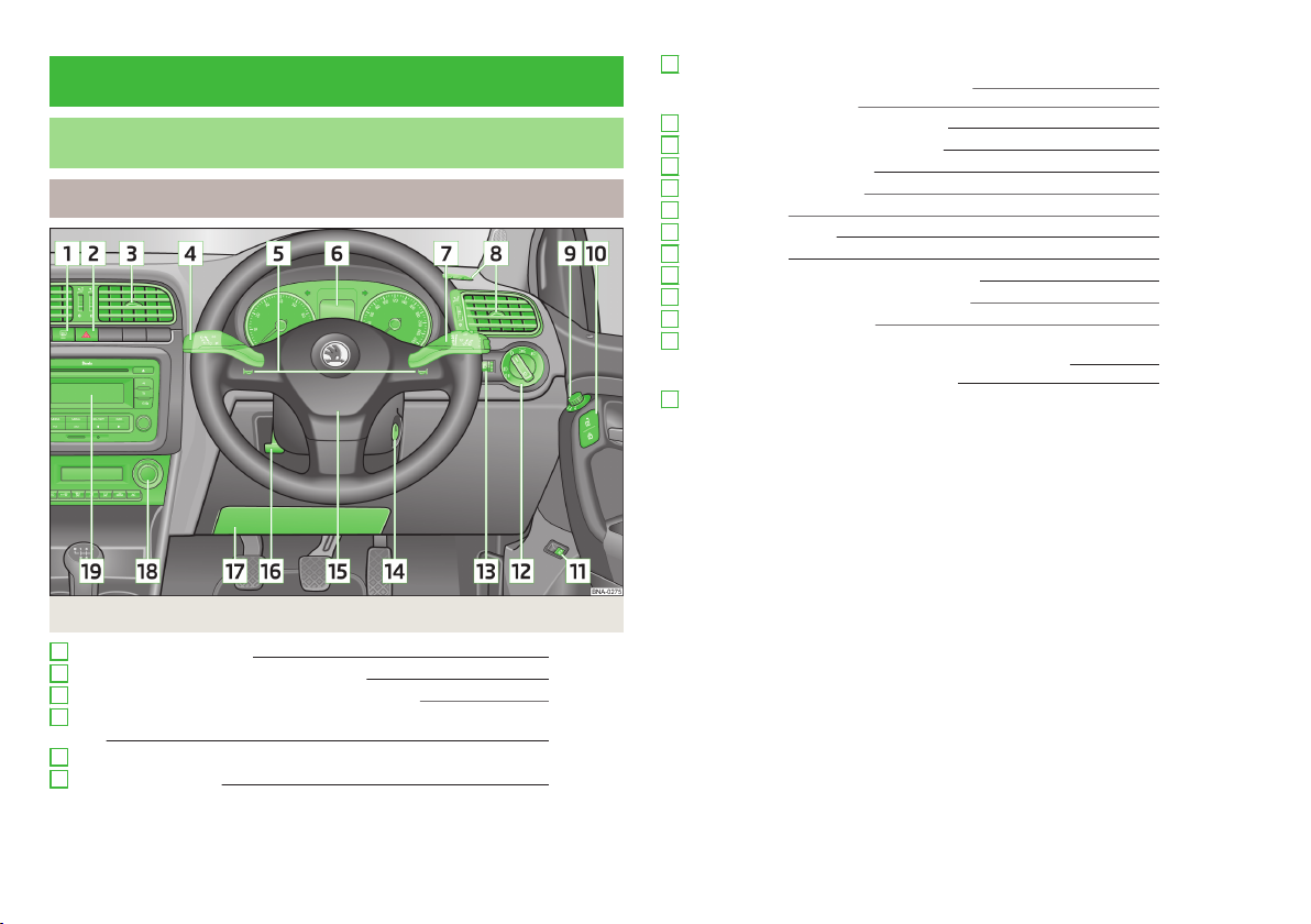
Cockpit
Fig. 1
1
Rear window heater
2
Button for hazard warning light system
3
Air outlets in the central part of the dash panel
4
Operating lever: Turn signal lights and main beam, headlight flasher 24
5
Horn
6
Instrument cluster
26
25
38
7
Operating lever:
Windscreen wiper and wash system 28
›
Information system 13
›
8
Air outlet vents on the driver's side 38
9
Electric exterior mirror adjustment 29
10
Central locking system
11
Bonnet remote release 86
12
Light switch 23
13
Lights and visibility 23
14
Ignition lock 43
15
Steering wheel and driver's front airbag 66
16
Lever for adjusting the steering wheel 41
17
Distribution board cover. 113
18
Depending on equipment fitted:
Operating controls for the air conditioning system
›
Operating controls for Climatronic 39
›
19
Radio
7
19
38
6
Usage

Instruments and Indicator Lights
Instrument cluster
Introduction
This chapter contains information on the following subjects:
Overview
Engine revolutions counter 8
Fuel gauge 8
Counter for distance driven 8
Digital clock 9
Fault display
If there is a fault in the instrument cluster, the Error message will appear in the
display. Have the fault rectified as soon as possible by a specialist garage.
WARNING
■
Concentrate fully at all times on your driving! As the driver you are fully re-
sponsible for road safety.
■
Never operate the controls in the instrument cluster while driving, only
when the vehicle is stationary!
Overview
7
Fig. 2 Instrument cluster
First read and observe the introductory information and safety warnings on page 7.
1
Revolutions counter with warning lights » page 8
2
Display:
With counter for distance driven » page 8
›
With service interval display » page 14
›
With digital clock » page 9
›
with multifunction display (MFA) » page 14
›
With information system » page 13
›
3
Speedometer with warning lights
4
Button for display mode:
Setting the hours/minutes » page 9
›
Service intervals - Display of the number of days and kilometres remaining
›
until the next service» page 14
5
Button for:
switch between the odometer and the trip odometer display » page 8
›
Reset trip odometer » page 8
›
Set hours/minutes » page 9
›
Instruments and Indicator Lights
7

Engine revolutions counter
First read and observe the introductory information and safety warnings on page 7.
The red scale of the rev counter 1 » fig. 2 on page 7 indicates the range in which
the system begins to limit the engine speed. The system automatically restricts
the engine speed to a steady limit.
You should shift into the next higher gear before the red scale of the revolution
counter is reached, or select mode D on the automatic gearbox.
Follow the recommended gear to prevent engine speeds that are too high or too
low » page 13.
For the sake of the environment
Correct shifting up has the following advantages.
■
It helps to reduce fuel consumption.
■
It reduces the operating noise.
■
It protects the environment.
■
It benefits the durability and reliability of the engine.
Fuel gauge
Fig. 3
Fuel gauge
First read and observe the introductory information and safety warnings
The fuel gauge only operates if the ignition is switched on.
The fuel tank has a capacity of about 55 litres. If the amount of fuel reaching the
reserve area, the indicator lights » page 11 on.
on page 7.
The reserve area is indicated by the display of only the last two segments
scale » fig. 3 .
CAUTION
Never drive until the fuel tank is completely empty! The irregular supply of fuel
can cause misfiring. This can result in considerable damage to parts of the engine
and the exhaust system.
Counter for distance driven
Fig. 4
With counter for distance driven
First read and observe the introductory information and safety warnings on page 7.
The change between the odometer and the trip odometer display is done by
pressing the button 5 » fig. 2 on page 7 .
Odometer
The odometer » fig. 4 indicates the total distance the vehicle has travelled.
Daily trip counter (trip)
The daily trip counter » fig. 4 shows the distance driven since the time the
counter was last reset - in steps of 100 m.
Reset trip odometer
With the 5 key » fig. 2 on page 7 choose the odometer display.
›
Press and hold the 5 button.
›
8
Usage

Digital clock
First read and observe the introductory information and safety warnings on page 7.
The clock is set with the buttons 4 and 5 » fig. 2 on page 7.
Button 4 - Select the display you want to change (hours or minutes).
5
button - change the display value.
Warning Lights
Introduction
This chapter contains information on the following subjects:
Handbrake
Braking system 9
Generator 10
Open door 10
warning light
Coolant
Power steering 11
Antilock brake system (ABS) 11
The rear fog light 11
Exhaust inspection system
Glow plug system (diesel engine)
EPC fault light (petrol engine) 11
Fuel reserve
Airbag system
Turn signal system
Selector lever lock
Main beam
The indicator lights show certain functions/faults and may be accompanied by audible signals.
WARNING
■
If illuminated indicator lights and the corresponding descriptions and warning notes are not observed, this may result in severe injuries or major vehicle
damage.
■
The engine compartment of your car is a hazardous area. There is a risk of
injuries, scalding, accidents and fire when working in the engine compartment, e.g. inspecting and replenishing oil and other fluids. It is essential to ob-
serve safety notes » page 84, Engine compartment.
Handbrake
First read and observe the introductory information and safety warnings
The indicator light comes on if the handbrake is applied. An audible warning is
also given if you drive the vehicle for at least 3 seconds at a speed of more than
9
6 km/h.
10
10
Braking system
The indicator light illuminates if the brake fluid level in the braking system is
too low or there is a fault in the ABS.
11
Stop the vehicle, switch off the engine, and check the level of the brake flu-
11
id » page 91.
11
12
12
12
12
WARNING
■
If you have to stop for technical reasons, then park the vehicle at a safe distance from the traffic, switch off the engine and activate the hazard warning
light system » page 25.
■
The following guidelines should be observed when opening the bonnet and
checking the brake fluid level » page 84, Engine compartment.
on page 9.
First read and observe the introductory information and safety warnings on page 9.
Instruments and Indicator Lights
9

WARNING (Continued)
■
If the warning light is displayed simultaneously with warning light
» page 11, Antilock brake system (ABS), do not continue your jour-
ney! Seek help from a specialist garage.
■
A fault to the ABS system or the braking system can increase the vehicle's
braking distance – risk of accident!
Generator
First read and observe the introductory information and safety warnings on page 9.
If the indicator light lights up when the engine is running, the vehicle battery is
not being charged.
Seek help from a specialist garage. The electrical system requires checking.
WARNING
If you have to stop for technical reasons, then park the vehicle at a safe distance from the traffic, switch off the engine and activate the hazard warning
light system » page 25, Hazard warning light systemHazard warning light
system.
Even if the oil level is correct, do not drive any further if the indicator light is
flashing . Also do not leave the engine running at an idling speed.
Seek help from a specialist garage.
WARNING
If you have to stop for technical reasons, then park the vehicle at a safe distance from the traffic, switch off the engine and activate the hazard warning
light system » page 25.
Coolant
First read and observe the introductory information and safety warnings on page 9.
If the indicator light lights up or flashes, either the coolant temperature is too
high or the coolant level is too low.
Stop the vehicle, switch off the engine, check the level of the coolant » page 90,
and refill the coolant if necessary » page 90.
Do not continue driving if the warning light is lit, even though the coolant level
is correct and the fuse for the fan is in working order!
Seek help from a specialist garage.
Open door
First read and observe the introductory information and safety warnings on page 9.
The indicator light comes on, if one or several doors are opened.
warning light
First read and observe the introductory information and safety warnings on page 9.
The indicator light light (low oil pressure)
Stop the vehicle, switch off the engine, and check the level of the engine
oil » page 88.
10
Usage
WARNING
■
If you have to stop for technical reasons, then park the vehicle at a safe distance from the traffic, switch off the engine and activate the hazard warning
light system » page 25.
■
Carefully open the coolant expansion bottle. If the engine is hot, the cooling
system is pressurized - risk of scalding! It is therefore best to allow the engine
to cool down before removing the cap.
■
Do not touch the radiator fan. The radiator fan may switch itself on automatically even if the ignition is off.
CAUTION
Additional headlights and other attached components in front of the air inlet impair the cooling efficiency of the coolant.

Power steering
First read and observe the introductory information and safety warnings on page 9.
If the indicator light lights up, there is a fault in the engine control.
The power steering operates with reduced steering assist or does not function at
all.
Seek help from a specialist garage.
When the indicator does not light up after starting the engine and traveling a
short distance, then the help of a professional operation must not be used.
If the battery is disconnected and reconnected, it is a short distance with a speed
of 15 - 20 km / h reading down.
Antilock brake system (ABS)
First read and observe the introductory information and safety warnings on page 9.
If the indicator light lights up, there is a fault in the ABS.
The vehicle will only be braked by the normal brake system without the ABS.
Seek help from a specialist garage.
WARNING
■
If you have to stop for technical reasons, then park the vehicle at a safe distance from the traffic, switch off the engine and activate the hazard warning
light system » page 25.
■
A fault to the ABS system or the braking system can increase the vehicle's
braking distance – risk of accident!
The rear fog light
First read and observe the introductory information and safety warnings on page 9.
The warning light comes on when the rear fog lights are operating » page 25.
Exhaust inspection system
First read and observe the introductory information and safety warnings on page 9.
If the indicator light lights up, there is a fault in the exhaust inspection system.
The engine control unit allows the vehicle to run in emergency mode.
Seek help from a specialist garage.
Glow plug system (diesel engine)
First read and observe the introductory information and safety warnings on page 9.
The indicator light comes on after the ignition has been switched on. The engine can be started immediately after the pre-glow indicator light goes out.
If the indicator light lights up, there is a fault in the engine control.
Seek help from a specialist garage.
EPC fault light (petrol engine)
First read and observe the introductory information and safety warnings on page 9.
If the indicator light
Seek help from a specialist garage.
Fuel reserve
First read and observe the introductory information and safety warnings
If the amount of fuel reaching the reserve area, the indicator lights on.
lights up, there is a fault in the engine control.
on page 9.
Instruments and Indicator Lights
11

CAUTION
Never drive until the fuel tank is completely empty! The irregular supply of fuel
can cause misfiring. This can result in considerable damage to parts of the engine
and the exhaust system.
Airbag system
First read and observe the introductory information and safety warnings on page 9.
If the indicator light lights up, there is a fault in the airbag system.
WARNING
If there is a fault, have the airbag system checked immediately by a specialist
garage. Otherwise, there is a risk of the airbag not being activated in the
event of an accident.
Turn signal system
First read and observe the introductory information and safety warn-
on page 9.
ings
Either the left or right indicator light flashes depending on the position of
the turn signal lever.
If a turn signal light fails, the indicator light flashes at twice its normal rate.
Switching off the hazard indicator light system is switched on will cause all of the
turn signal lights as well as both indicator lights to flash.
Further information » page 24, Turn signal and main beam.
Main beam
First read and observe the introductory information and safety warnings on page 9.
The indicator light comes on when the main beam or headlight flasher are selected » page 24.
Selector lever lock
First read and observe the introductory information and safety warnings on page 9.
If the indicator light lights up, operate the brake pedal.
12
Usage

Information system
Driver information system
Introduction
This chapter contains information on the following subjects:
Ice warning
Gear recommendation 13
Service Interval Display 14
The information system provides the driver with alerts and messages about individual vehicle systems. This information and instructions are displayed on the
display of the instrument cluster.
The information system provides the following information.
Ice warning » page 13.
›
Recommended gear » page 13.
›
Multi-function display (MFA) » page 14.
›
Warning against excessive speed » page 16.
›
Service interval display » page 14.
›
Selector lever positions for an automatic gearbox » page 47.
›
WARNING
Concentrate fully at all times on your driving! As the driver you are fully responsible for the operation of your vehicle.
Ice warning
First read and observe the introductory information and safety warnings on page 13.
If the outside temperature while driving drops to below +4°C, the temperature
display » page 15, Outside temperature will show up with the following icon in
front . An audible signal is emitted.
If the outside temperature is already below +4°C when turning the ignition on,
the temperature display and the icon appear immediately. An audible signal is
emitted.
WARNING
Even at temperatures of around +4 °C, black ice may still be on the road surface! You should therefore not only rely on the outside temperature display
for accurate information as to whether there is ice on the road.
Notice
Applies to cars with the multi-function display (MFA).
13
Gear recommendation
First read and observe the introductory information and safety warnings on page 13.
In order to minimise the fuel consumption, a recommendation for shifting into another gear is indicated in the display.
Symbol Importance
The selected gear is optimal.
Recommends that you shift to a higher gear.
Recommends that you shift to a lower gear.
CAUTION
The driver is always responsible for selecting the correct gear in different driving
situations, such as overtaking.
For the sake of the environment
The journey with useful gear can positively impact fuel consumption.
Notice
Produced when the clutch pedal is not recommended gear indicator.
Information system
13

Service Interval Display
First read and observe the introductory information and safety warnings on page 13.
If a service due date, then the following information is displayed for about 10 seconds.
Icon and the days remaining until the next service interval
›
Icon and the days remaining until the next service interval
›
The kilometre indicator or the days indicator reduces in steps of 100 km or, where
applicable, days until the service due date is reached.
As soon as the due date for the service is reached, the flashing key symbol and
the text
been switched on.
Display the days and distance until the next service interval
You can press button
distance and days until the next service interval whenever the ignition is switched on.
appears in the display for about 20 seconds after the ignition has
5
» fig. 2 on page 7 continuously to display the remaining
Notice
■
Information is retained in the Service Interval Display even after the vehicle bat-
tery is disconnected.
■
If the instrument cluster is exchanged after a repair, the correct values must be
entered in the counter for the Service Interval Display. This work is carried out by
a specialist garage.
■
For more information on the service intervals » service schedule, chapter service intervals.
Multifunction display (MFA)
Introduction
This chapter contains information on the following subjects:
Operation 14
Memory 15
Information overview
Warning against excessive speeds
The driving data is displayed on the multifunction display.
The multifunction display can only be operated when the ignition is switched on.
After the ignition is switched on, the function that was last selected before
switching off the ignition is displayed.
WARNING
■
Concentrate fully at all times on your driving! As the driver you are fully re-
sponsible for the operation of your vehicle.
■
Even at temperatures of around +4 °C, black ice may still be on the road surface! You should therefore not only rely on the outside temperature display
for accurate information as to whether there is ice on the road.
Operation
Fig. 5
Buttons on the control lever
First read and observe the introductory information and safety warn-
15
16
ings on page 14.
The multi-function display can be operated with the buttons on the control lever » fig. 5 .
Description of the operation
Button
A
B
Action Operation
push up or down briefly Select data / set data values
press briefly Show indication / confirm information
14
Usage

Memory
Fig. 6
Multi-function display - Display
example of the memory
Press the button B » fig. 5 on page 14 for longer.
›
The following values of the selected memory are set to zero.
Average fuel consumption.
›
Distance driven.
›
Average speed.
›
Driving time
›
Notice
All information in the memory 1 and 2 is erased if the battery of the vehicle is dis-
connected.
First read and observe the introductory information and safety warnings on page 14.
The multifunction display is equipped with two automatic memories, 1 and 2. The
selected memory is shown in the Display » fig. 6.
Single-trip memory (memory 1)
The single-trip memory collates the driving information from the moment the ignition is switched on until it is switched off. New data will also flow into the calculation of the current driving information if the trip is continued within 2 hours
after switching off the ignition. If the trip is interrupted for more than 2 hours,
the memory is automatically erased.
Total-trip memory (memory 2)
The total distance driven memory gathers data from any number of individual
journeys up to a total of 19 hours and 59 minutes driving or 1 999 kilometres driven. The memory is deleted when either of these limits is reached and the calculation starts all over again.
Unlike the single-trip memory, the total-trip memory is not deleted after a period
of interruption of driving of 2 hours.
Select memory
Select the corresponding element of the multi-function display » page 14, Oper-
›
ation.
Press the button B » fig. 5 on page 14 for longer.
›
Reseting
Select the corresponding element of the multi-function display » page 14, Oper-
›
ation.
Select the desired memory.
›
Information overview
First read and observe the introductory information and safety warnings
Outside temperature
The current outside temperature is displayed.
Driving time
The driving time which has elapsed since the memory was last erased appears in
the display. If you want to measure the time travelled from a particular moment in
time on, at this moment, reset the memory by setting the button to
zero » page 15, Memory.
The maximum distance indicated in both memories is 19 hours and 59 minutes.
The indicator is set back to zero if this period is exceeded.
Current fuel consumption
The current fuel consumption level is displayed in litres/100 km. You can use this
information to adapt your driving style to the desired fuel consumption.
The display appears in litres/hour if the vehicle is stationary or driving at a low
speed.
Average fuel consumption
The average fuel consumption since the memory was last erased is displayed in
litres/100 km.
If you wish to determine the average fuel consumption over a certain period of
time, you must set the memory at the start of the new measurement to
zero » page 15, Memory. After erasing the memory, no value is displayed until you
have driven approx. 300 m.
on page 14.
Information system
15

The display is updated regularly while you are driving.
Range
The estimated range is displayed in kilometres. It indicates the distance you can
still drive with your vehicle based on the level of fuel in the tank and the same
style of driving.
The display is shown in steps of 10 km. After lighting up of the indicator light
the display is shown in steps of 5 km.
The fuel consumption over the last 50 km is used to calculate the information.
The range will increase if you drive in a more economical manner.
If the memory is set to zero (after disconnecting the battery), a fuel consumption
of 10 l./100 km is calculated for the range; afterwards the value is updated according to the style of driving.
Distance travelled
The distance travelled since the memory was last erased is displayed » page 15,
Memory. If you want to measure the distance travelled from a particular moment
in time on, at this moment, reset the memory by setting the button to
zero » page 15, Memory.
The maximum distance indicated in both memories is 999 km. The indicator is set
back to zero if this period is exceeded.
Average speed
The average speed since the memory was last erased is displayed in km/
hour » page 15, Memory. To determine the average speed over a certain period of
time, set the memory to zero at the start of the measurement » page 15, Memory.
After erasing this data, no value appears in the display until you have driven approx. 300 m.
The display is updated regularly while you are driving.
Current speed
The current speed, which is identical to the display of the speedometer
on page 7 is displayed.
Warning against excessive speeds
The warning that the speed limit is being exceeded can be enabled / disabled » page 16, Warning against excessive speeds in the display.
3
» fig. 2
Warning against excessive speeds
First read and observe the introductory information and safety warnings on page 14.
Adjust the speed limit while the vehicle is stationary
Select the menu item.
›
Activate the speed limit option by confirming this menu item1).
›
Set the desired speed limit, e.g. 50 km/h.
›
Store the speed limit by confirming the set value, or wait several seconds; your
›
settings will be saved automatically.
The speed limit can be adjusted from 30 km/h to 250 km/h in 5 km/h increments.
Adjusting the speed limit while the vehicle is moving
Select the menu item.
›
Drive at the desired speed, e.g. 50 km/h.
›
Confirm the current speed as the speed limit.
›
If you wish to adjust the set speed limit, you can do so in 5 km/h intervals (e.g. the
accepted speed of 47 km/h increases to 50 km/h or decreases to 45 km/h).
Store the speed limit, or wait several seconds; your settings will be saved auto-
›
matically.
Change or disable speed limit
Select the menu item.
›
By confirming the stored value, the speed limit is disabled.
›
By reconfirming, the option to change the speed limit is activated.
›
If the set speed limit is exceeded, an audible signal will sound as a warning. At
the same time the menu item is displayed with the set threshold.
The set speed limit value remains stored even after switching off the ignition.
1)
If no value is set the output value 30 km/h is automatically displayed.
16
Usage

Unlocking and opening
Unlocking and locking
Introduction
This chapter contains information on the following subjects:
Vehicle key
Unlocking/locking with the key 18
Unlock/lock with remote control 18
Locking/unlocking the vehicle from the inside 19
Child safety lock 19
Opening/closing a door 20
Your car is equipped with a central locking system.
The central locking system allows you to lock and unlock all doors, the fuel filler
flap and tailgate at the same time based on the current setting.
The following is true after unlocking.
The doors, the boot lid and the fuel filler flap are unlocked.
›
The interior light, which is switched by the door contact, comes on.
›
The indicator light in the driver door stops flashing.
›
The following is true after locking.
The doors, the boot lid and the fuel filler flap are locked.
›
The interior lights switched by the door contact come on.
›
The indicator light in the driver door begins flashing.
›
Automatic locking
All the doors and the boot lid are locked automatically once the car reaches a
speed of about 9 km/h.
Displaying an error
If the indicator light in the driver's door initially flashes quickly for around 2 seconds, and then lights up for 30 seconds without interruption before flashing
again slowly, you will need to seek the assistance of a specialist garage.
Notice
■
In the event of an accident in which the airbags are deployed, the locked doors
are automatically unlocked in order to enable rescuers to gain access to the vehicle.
■
Only the driver's door can be unlocked or locked using the key if the central
locking system fails » page 18. The other doors can be notverriegeln or emergency release » page 110 .
17
Vehicle key
First read and observe the introductory information given on page 17.
Two keys are provided with the vehicle.
The transmitter with the battery is housed in the handle of the remote control
key. The receiver is located in the interior of the vehicle. The operating range of
the remote control key is approx. 30 m. But this range of the remote control can
be reduced if the batteries are weak.
The remote control key has a fold-open key bit which can be used for unlocking
and locking the car manually and also for starting the engine.
WARNING
Always withdraw the key whenever you leave the vehicle - even if it is only for
a short time. This is particularly important if children are left in the vehicle.
Otherwise, the children might start the engine or operate electrical equipment
(e.g. power windows) – risk of injury!
CAUTION
■
Each key contains electronic components; therefore it must be protected
against moisture and severe shocks.
■
Keep the groove of the keys absolutely clean. Impurities (textile fibres, dust,
etc.) have a negative effect on the functionality of the locking cylinder and ignition lock.
■
The battery must be replaced if the central locking only reacts to the remote
control at less than 3 metres away » page 109.
Unlocking and opening
17
Notice
■
The spare key must by initialised by a specialist garage after repair or replace-
ment of the receiver unit. Only then can the remote control key be used again.
■
If you lose a key, please contact a specialist garage, who will be able to provide
you with a new one.
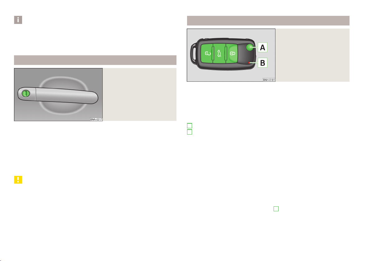
Unlocking/locking with the key
Fig. 7
Right side of the vehicle: Locking
cylinder
First read and observe the introductory information given on page 17.
Unlocking
Turn the key in the locking cylinder of the driver's door in the direction of arrow
›
B .
Locking
Turn the key in the locking cylinder of the driver's door in the opposite direction
›
of travel (lock position) B .
CAUTION
If the driver's door has been opened, the vehicle cannot be locked.
Unlock/lock with remote control
Fig. 8
First read and observe the introductory information given on page 17.
Remote control key
Explanation of graphic
Unlocking the vehicle
Locking the vehicle
Unlocking the boot lid
A
Folding out/folding up of the key bit
B
Indicator light for battery condition
Unlocking
The turn signal lights flash twice as confirmation that the vehicle has been unlocked.
If the vehicle is unlocked and opened within the next 30 seconds with no door or
the boot lid, the vehicle is automatically locked again. This function is intended to
prevent the car being unlocked unintentionally.
Locking
The turn signal lights flash once as confirmation that the vehicle has been locked.
If the doors or the boot lid remain open after the vehicle has been locked, the
turn signal lights do not flash until they have been closed.
Checking the battery condition
The battery is empty if the red warning icon
press a button on the remote control key. Replace the battery » page 109.
B
» fig. 8 does not flash when you
18
Usage

CAUTION
■
If the driver's door has been opened, the vehicle cannot be locked.
■
The operation of the remote control may temporarily be affected by signal interference from transmitters close to the car and which operate in the same frequency range (e.g. mobile phone, TV transmitter).
Notice
The remote control will operate only when visual contact with the vehicle.
The doors can be unlocked and opened from the inside by a single pull on the
›
opening lever of the respective door.
In the event of an accident in which the airbags are deployed, the locked doors
›
are automatically unlocked from the inside in order to enable rescuers to gain
access to the vehicle.
WARNING
■
Doors locked from the inside make it difficult for rescuers to get into the ve-
hicle in an emergency – risk to life!
■
Never leave children unattended in the vehicle.
Locking/unlocking the vehicle from the inside
Fig. 9
Driver's door: Central locking
button
First read and observe the introductory information given on page 17.
If the vehicle was not locked from the outside, you can also unlock or lock it with
the button » fig. 9 without the ignition switched on.
Explanation of graphic
Unlocking
Locking
The following applies if your vehicle has been locked using the central locking
button.
The symbol in the button is no longer illuminated.
›
Opening the doors and the boot lid from the outside is not possible.
›
CAUTION
If at least one door has been opened, the vehicle cannot be locked.
Child safety lock
Parental Control: Left rear door / rear right door
Fig. 10
First read and observe the introductory information given on page 17.
The child safety lock prevents the rear door from being opened from the inside.
The door can only be opened from the outside.
You can switch the child safety lock on and off using the vehicle key.
Explanation of graphic
A
Child safety lock off.
B
Child safety lock on.
Unlocking and opening
19
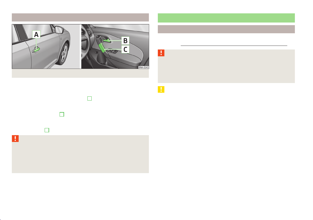
Opening/closing a door
Fig. 11 Door handle/door opening lever:
First read and observe the introductory information given on page 17.
Opening from the outside
Unlock the vehicle and pull the door handleA » fig. 11 on the door you wish to
›
open.
Opening from the inside
Pull on door opening lever B of the respective door and push the door away
›
from you.
Closing from the inside
Grasp pull handle C and close the door.
›
WARNING
■
Make sure that the door has closed correctly as it can open suddenly while
driving – risk of death!
■
Only open and close the door when there is no one in the opening/closing
range – risk of injury!
■
An opened door can close automatically if there is a strong wind or the vehi-
cle is on an incline – risk of injury!
Luggage compartment lid
Introduction
This chapter contains information on the following subjects:
open / close
WARNING
■
Ensure that the lock is properly engaged after closing the boot lid. Otherwise, the boot lid might open suddenly while the vehicle is moving, even it
was locked – risk of accident!
■
Never drive with the boot lid open or ajar, as otherwise exhaust gases may
get into the interior of the vehicle – risk of poisoning!
CAUTION
If the vehicle was locked before the boot lid was closed, the lid is immediately
locked automatically when closed.
21
20
Usage

open / close
Fig. 12 With button lid unlocked / open door key from outside
Notice
Before closing the boot lid, check that the vehicle key is not in the boot.
Electric power windows
Introduction
This chapter contains information on the following subjects:
Opening/closing the windows 22
Force limit 22
The power windows operate only when ignition is switched on.
Fig. 13
Handle in the inner panelling of
the boot lid
First read and observe the introductory information and safety warnings
Unlocking
The lid can be unlocked in one of the following ways.
On the key, the symbol button » fig. 12 press and hold.
›
In the driver's door on the Symbol key draw.
›
Turn the lock on the door with the key clockwise 1 » fig. 12 .
›
Opening
Pull the foldable luggage compartment cover in direction of arrow 2 as far as
›
the stop into the secured position.
Closing
Pull the lid down with the handle » fig. 13 and close with a slight swing.
›
on page 20.
WARNING
■
Ensure that no persons are still left in the vehicle when locking the vehicle.
In an emergency, the windows will no longer be able to be opened from the
inside.
■
It is recommended to deactivate the electrically operated power windows in
the rear doors (safety pushbutton) S » fig. 14 on page 22 when children are
being transported on the rear seats.
■
The electrical power windows are fitted with a force limiter » page 22. If
there is an obstacle, the closing process is stopped and the window goes
down by several centimetres. However, the windows should be closed carefully – risk of injury.
CAUTION
■
Keep the windows clean to ensure the correct functionality of the electric win-
dows.
■
In the event that the windows are frozen, first of all eliminate the
ice » page 75, De-icing windows and exterior mirrors and only then operate the
electrical power windows. Otherwise, the window sealing and the electrical power window mechanism could be damaged.
■
Make sure that the windows are closed whenever you leave the locked vehicle.
Unlocking and opening
21
For the sake of the environment
At high speeds, you should keep the windows closed to prevent unnecessarily
high fuel consumption.
Notice
When driving always use the existing heating, air conditioning and ventilation
system for ventilating the interior of the vehicle. If the windows are opened, dust
as well as other dirt can get into the vehicle and in addition the wind noise is
more at certain speeds.
Opening/closing the windows
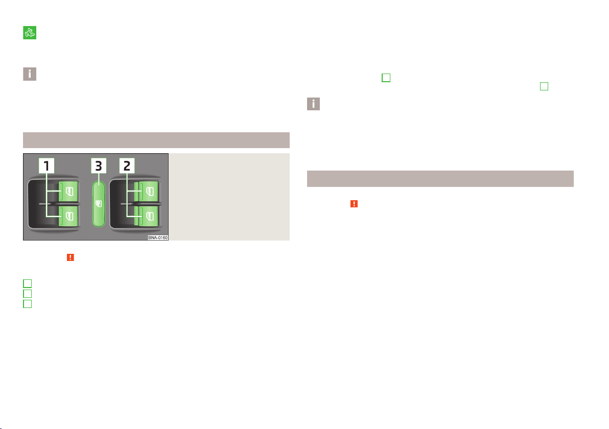
Fig. 14
Buttons on the driver's door
First read and observe the introductory information and safety warnings on page 21.
Explanation of graphic
1
Front window operation
2
Rear window operation
3
Safety pushbutton
Opening
The opening process of the window is started by pressing the corresponding
›
key light. The opening process stops when one releases the button.
Additionally, the window can be opened automatically (fully open) by pressing the
button to the stop. Renewed pressing of the button causes the window to stop
immediately.
Closing
The closing of the window is started by pulling lightly on the top of each key.
›
The closing process stops when one releases the button.
Safety pushbutton
The buttons for power windows in the rear doors can be deactivated by pressing
the safety pushbutton S » fig. 14. The buttons for the electrical power windows
in the rear doors are activated again by pressing the safety pushbutton S again.
Notice
The window lift mechanism is equipped with protection against overheating. Repeated opening and closing of the window can cause this mechanism to overheat. If this happens, it will not be possible to operate the window for a short
time. You will be able to operate the window again as soon as the overheating
protection has cooled down.
Force limit
First read and observe the introductory information and safety warnings
The electrical power windows are fitted with a force limiter. It reduces the risk of
bruises or injuries when closing the windows.
If there is an obstacle, the closing process is stopped and the window goes down
by several centimetres.
If the obstacle prevents the window from being closed during the next 10 seconds, the closing process is interrupted once again and the window goes down by
several centimetres.
If you attempt to close the window again within 10 seconds of the window being
moved down for the second time, even though the obstacle was not yet been removed, the closing process is only stopped. The force limiter is still switched on.
The force limiter is only switched off if you attempt to close the window again
within the next 10 seconds - the window will now close with full force!
If you wait longer than 10 seconds, the force limiter is switched on again.
on page 21.
22
Usage

Lights and visibility
Lights
Introduction
This chapter contains information on the following subjects:
Side lights and low beam
Turn signal and main beam 24
Fog lightsFog lights 24
Rear fog light 25
Hazard warning light systemHazard warning light system 25
WARNING
■
The activation of the lights should only be undertaken in accordance with
national legal requirements.
■
The driver is always responsible for the correct settings and use of the
lights.
■
Never drive with only the side lights on! The side lights are not bright
enough to light up the road sufficiently in front of you or to be seen by other
oncoming traffic. Therefore always switch on the low beam when it is dark or
if visibility is poor.
Notice
The headlights may mist up temporarily. When the driving lights are switched on,
the light outlet surfaces are free from mist after a short period, although the
headlight lenses may still be misted up in the peripheral areas. This mist has no
influence on the life of the lighting system.
Side lights and low beam
Fig. 15
Light switch and control dial for
the headlight beam range regulation
23
First read and observe the introductory information and safety warn-
ings on page 23.
A
light switch positions» fig. 15
Switching off all lights
Switching on side lights
Turn on the low beam
Switch on the front fog lamp » page 24
Switching on the rear fog light » page 25
Lights and visibility
Turning the rotary switch from position
gradually adjusted and thereby shortens the light cone.
The positions of the width of illumination correspond approximately to the following car load.
Front seats occupied, boot empty
All seats occupied, boot empty
All seats occupied, boot loaded
Driver seat occupied, boot loaded
B
in the headlight adjustment is
WARNING
Always adjust the headlight beam to satisfy the following conditions.
■
The vehicle does not dazzle other road users, especially oncoming vehicles.
■
The beam range is sufficient for safe driving.
Lights and visibility
23
Notice
■
We recommend you adjust the headlight beam when the low beam is switched
on.
■
An audible warning signal will sound if the light switch is in the or position, the ignition key is removed and the driver's door is opened. The audible
warning signal is switched off by means of the door contact when the driver's
door is closed (ignition off), however, the side lights remain on to illuminate the
parked vehicle if necessary.
Turn signal and main beam
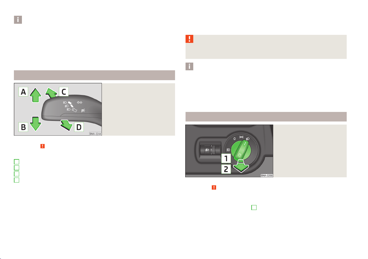
Fig. 16
Operating lever: Turn signal and
main beam operation
First read and observe the introductory information and safety warnings
Lever positions » fig. 16
A
Switch on right turn signal
B
Switch on left turn signal
C
Remote Light Switch
D
Switch off main beam or switch on headlight flasher (spring-tensioned position)
When the left or right turn signal is on, the warning light or flashes in the
instrument cluster.
When the high beam or headlight flasher is on, the warning light lights up in
the instrument cluster.
Turn signal for changing lanes - to only flash briefly, only move the lever up or
down to the pressure point and hold it in this position.
on page 23.
Convenience turn signal
If you only wish to flash three times, briefly push the lever to the upper or lower
pressure point and release again.
WARNING
Only turn on the main beam or the headlight flasher if other road users will
not be dazzled.
Notice
■
The main beam can only be switched on when the low beam lights are on.
■
The headlight flasher can be operated even if the ignition is switched off.
■
The turn signal light switches itself off automatically when driving around a
curve or after making a turn.
■
The indicator light flashes at twice its normal rate if a bulb for the turn signal
light fails.
Fog lightsFog lights
Fig. 17
Light switch
First read and observe the introductory information and safety warnings on page 23.
Switching on/off
Turn the light switch to position or » fig. 17.
›
Pull the light switch to position 1.
›
The rear fog light is switched off in the reverse order.
24
Usage

Rear fog light
First read and observe the introductory information and safety warnings on page 23.
Switching on/off
Turn the light switch to position or » fig. 17 on page 24.
›
Pull the light switch to position 2.
›
The rear fog light is switched off in the reverse order.
The warning light lights up in the instrument cluster when the rear fog light is
switched on » page 11.
Hazard warning light systemHazard warning light system
Fig. 18
Button for hazard warning light
system
First read and observe the introductory information and safety warnings
Switching on/off
Press the button
›
All the turn signal lights on the vehicle flash at the same time when the hazard
warning light system is switched on. The warning light for the turn signals and
the warning light in the button also flash at the same time. The hazard warning
light system can also be operated if the ignition is switched off.
If one of the airbags is deployed, the hazard warning light system will switch on
automatically.
If at the hazard warning lights and ignition, the flashing light is turned on, then
only the flashing light on the respective side of the vehicle flash.
on page 23.
» fig. 18 .
CAUTION
Switch on the hazard warning light system if, for example, the following occurs.
■
You encounter a traffic congestion.
■
The vehicle has broken down.
Interior light
Front interior light
Fig. 19
Interior lights at the front
Rocker switch positions » fig. 19.
switching on
control using the door contact switch (middle position)
switching off
If operating the light with the door contact switch is enabled (in the position)
the light will come on when one of the following events occurs:
The vehicle is unlocked.
›
One of the doors is opened.
›
The ignition key is removed.
›
If operating the light with the door contact switch is enabled (in the position)
the light will go off when one of the following events occurs:
The vehicle is locked.
›
The ignition is switched on.
›
About 30 seconds after all the doors have been closed.
›
Lights and visibility
25

Notice
If the interior light remains switched on when the ignition is switched off or if one
of the doors is open, the light will automatically go out after around 10 minutes.
Rear interior light
Fig. 20
Interior lights at the rear
Rocker switch positions » fig. 19 on page 25.
switching off
Reading lamp left
Operating the light with the door contact switch
Reading lamp right
switching on
The same principles apply for the interior lighting as for » page 25.
Visibility
Introduction
This chapter contains information on the following subjects:
Rear window heater
Sun visorsSun visors
Rear window heater
First read and observe the introductory information given on page 26.
Fig. 21
Button for hazard warning light
system
Switch the rear window heater on/off
When the heater is switched on, a lamp lights up inside the button.
The rear window heater only operates when the engine is running.
The rear window heater switches off automatically after 7 minutes.
For the sake of the environment
The heating should be switched off as soon as the window is de-iced or free from
mist. The reduced current consumption will have a favourable effect on fuel econ-
omy » page 53, Saving electrical energy.
Notice
■
If the on-board voltage drops, the rear window heater switches off automatically, in order to provide sufficient electrical energy for the engine control » page 95, Automatic load deactivation.
■
If the light is flashing inside the button the heater is off due to low battery.
26
27
26
Usage
Sun visorsSun visors
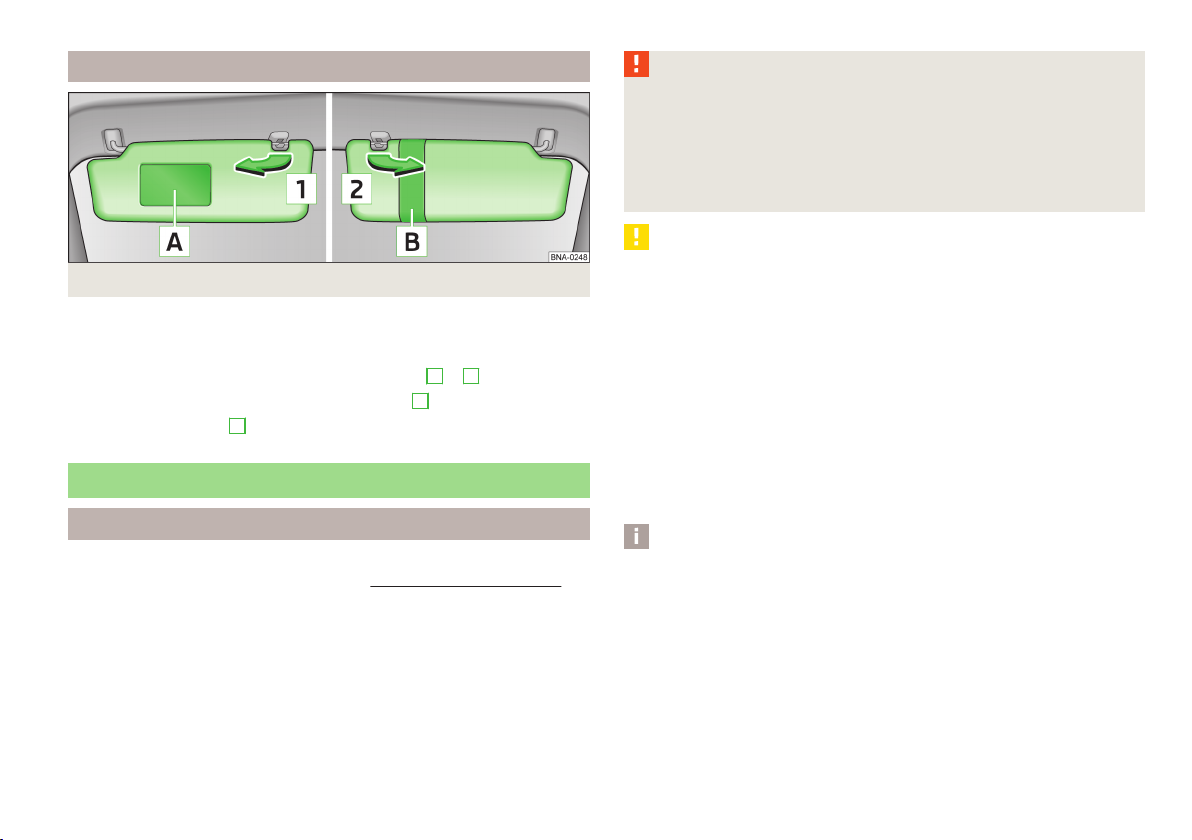
Fig. 22 Sun visors
First read and observe the introductory information given on page 26.
The sun visor for the driver or front passenger can be pulled out of the fixture and
swivelled towards the door in the direction of the arrow 1 or 2 » fig. 22.
In the sun visor for the passenger is a make-up mirror
The purpose of the strap A is to store small, light objects, such as a notepad, etc.
Windscreen wipers and washers
Introduction
This chapter contains information on the following subjects:
Activating the windshield wipers and washers 28
The windshield wipers and the windshield washer system only operate if the ignition is switched on.
Top up with windscreen wiper fluid » page 87.
A.
WARNING
■
Properly maintained windscreen wiper blades are essential for clear visibility
and safe driving » page 111.
■
Do not use the windscreen washer system at low temperatures, without
heating the windscreen beforehand. Otherwise the window cleaner could
freeze on the windscreen and restrict the view to the front.
■
Replace the windscreen wiper blades once or twice a year for safety reasons. These can be purchased from a ŠKODA Partner.
CAUTION
■
In cold temperatures and during the winter, check before the journey or before
switching on the ignition that the wiper blades are not frozen to the windscreen.
If the windscreen wipers are switched on when the blades are frozen to the
windscreen, this may damage both the blades and windscreen wiper motor!
■
If the ignition is switched off while the windscreen wipers are switched on, the
windscreen wipers will continue wiping in the same mode after the ignition is
turned back on. The windscreen wipers could freeze up in cold temperatures between the time the ignition was turned off and when it was turned back on again.
■
Carefully peel is Frozen wiper blades from the windshield.
■
Remove snow and ice from the windscreen wipers before driving.
■
If the windscreen wipers are handled carelessly, there is a risk of damage to the
windscreen.
■
The ignition must not be switched on if the front windscreen wiper arms are fol-
ded out. The wiper blades would move back into their rest position and while doing so damage the paintwork of the bonnet.
Notice
Keep the wiper blades clean. They may become soiled, e.g., with wax residues after washing in automatic car wash systems » page 72.
Lights and visibility
27
Activating the windshield wipers and washers
Rear mirror
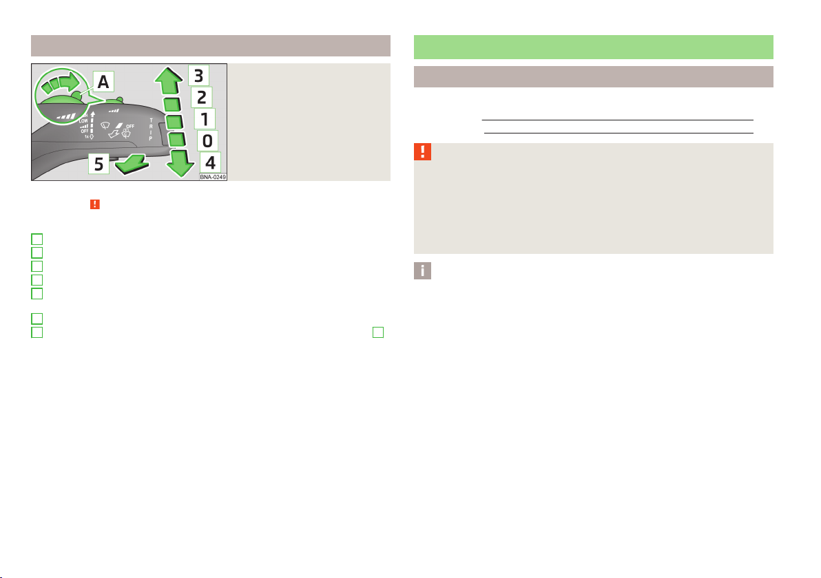
Fig. 23
Operating lever: Windscreen
wipers and washer settings
First read and observe the introductory information and safety warnings on page 27.
Lever positions » fig. 23
0
Wipers off
1
Windscreen wiper blade
2
slow windscreen wiping
3
rapid windscreen wiping
4
Tip wiping the windshield, service position of the wiper arms (spring-loaded
position) » page 111
5
Automatic wipe/wash for windscreen (spring-tensioned position)
A
Switch for setting the desired break between the individual wiper rashes
interval wiping the windscreen)
Automatic wash/wipe
The wash system operates immediately, the windscreen wipers wipe somewhat
later.
Letting go of the lever will cause the windscreen wash system to stop and the
wiper to continue for another 1-3 wiper strokes (depending on the period of
spraying of the windscreen).
Introduction
This chapter contains information on the following subjects:
Interior mirror
Exterior mirror 29
WARNING
■
Make sure that the mirror is not covered by ice, snow, mist or other objects.
■
Convex (curved outward) or aspheric exterior mirrors increase the field of vision. They do, however, make objects appear smaller in the mirror. These mirrors are therefore only of limited use for estimating distances to the following
vehicles.
■
Whenever possible use the interior mirror for estimating the distances to
the following vehicles.
Notice
■
The power steering only works when the engine is running.
■
Do not touch the surface of the exterior mirrors if the exterior mirror heater is
switched on.
■
(1
If the electrical exterior mirror setting fails at any time, the mirrors can be adjus-
ted by hand by pressing on the edge of the mirror surface.
■
Contact a specialist garage if there is a fault with the power setting function for
the exterior mirrors.
29
28
Usage

Interior mirror
Fig. 24
Interior rear-view mirror
First read and observe the introductory information and safety warnings on page 28.
Dimming mirror
The lever on the rear view mirror in the direction of arrow A » fig. 24 Set.
›
Basic setting
Adjust the lever on the rear view mirror in the direction of arrow
›
B.
Exterior mirror
Fig. 25
Driver's door - Knob for door mirrors
The knob can be moved into the following positions.
Adjust the left mirror
Switch off mirror control
Adjust right mirror
Folding in the exterior mirrors
The entire exterior mirrors can be manually folded towards the side windows. To
restore the original position, this is folded back from the window to side it clicks.
First read and observe the introductory information and safety warnings on page 28.
The movement of the mirror surface is identical to the movement of the rotary
knob.
By moving the knob in the direction of the arrow, the mirror can be adjusted to
the desired position » fig. 25.
Lights and visibility
29

Seats and useful equipment
Adjusting the seats
Introduction
This chapter contains information on the following subjects:
AdjustAdjust the front seats
Head restraints 31
Armrest 32
Observe the following instructions for the correct seated position » page 57.
Correct adjustment of the seats is particularly important:
for achieving maximum protection from the seat belts and the airbag system.
›
for safely and quickly reaching the controls;
›
for a relaxed body position that reduces fatigue;
›
WARNING
General information
■
Caution when adjusting the seat! You may suffer injuries or bruises as a re-
sult of adjusting the seat without paying proper attention.
■
The seat backrests must not be tilted too far back when driving, as this will
impair the function of the seat belts and of the airbag system – risk of injury!
■
Never carry more people than the number of seats in the vehicle.
■
Each occupant must correctly fasten the seat belt belonging to the seat.
Children must be fastened » page 69, Transporting children safely with a
suitable restraint system.
■
The front seats and head restraints must be adjusted to match the body
size at all times and the seat belt must always be fastened properly to provide
the most effective levels of protection to the passengers.
■
Do not carry any objects on the front passenger seat except objects designed for this purpose (e.g. child seats) – risk of accident!
WARNING
Information for the driver
■
Only adjust the driver's seat when the vehicle is stationary – risk of accident!
■
Keep a distance of at least 25 cm from the steering wheel. Not maintaining
this minimum distance will mean that the airbag system will not be able to
properly protect you - hazard!
■
Ensure that there are no objects in the driver's footwell, as these may get
caught in the pedal apparatus when driving or braking » page 47. You would
then no longer be able to operate the clutch, brake or accelerate.
31
WARNING
Information for the front seat passenger
■
Maintain a distance of at least 25 cm to the dash panel. Not maintaining this
minimum distance will mean that the airbag system will not be able to properly protect you - hazard!
■
Always keep your feet in the footwell when the car is being driven - never
place your feet on the instrument panel, out of the window or on the surfaces
of the seats. You will be exposed to increased risk of injury if it becomes necessary to apply the brake or in the event of an accident. If an airbag is deployed, you may suffer fatal injuries when adopting an incorrect seated position!
Notice
After a certain time, play can develop within the adjustment mechanism of the
backrest angle.
30
Usage

AdjustAdjust the front seats
Head restraints
Fig. 27
Head restraint
Fig. 26 Controls on the rear / front seat
First read and observe the introductory information and safety warnings
Adjusting a seat in a forward/back direction
Pull lever 1 » fig. 26 - (in the middle) in the arrow direction and slide the seat
›
in the desired direction.
The lock must click into place after you release the lever.
Adjusting the angle of the seat backrest
Remove the load on the seat backrest (do not lean on it), pull the lever
›
2
» fig. 26 towards the rear and set the desired angle of the seat backrest with
the back.
After releasing the lever 2, the seat backrest will remain in the set position.
Adjusting height of seat
Pull or push lever 3 » fig. 26 repeatedly in the direction of the arrows to set
›
the desired seat height.
The front seat can also be adjusted backwards/forwards from the rear. Pull lever
1
» fig. 26 up and push the seat in the desired position. The lock must click
into place after you release the lever. Adjust the seat only when it is not occupied.
on page 30.
First read and observe the introductory information and safety warnings on page 30.
Best protection is achieved if the top edge of the head restraint is at the same
level as the upper part of the head.
Set the height of the front headrests
Grasp the side of the head restraint with both hands and push it upwards as re-
›
quired.
To move the head restraint downwards, press and hold the safety button
›
1
» fig. 27 with one hand and press the head restraint downwards with the
other hand.
Removing and installing a head restraint
Pull the head restraint out of the seat backrest as far as the stop.
›
Press safety button 1 » fig. 27 and pull out the headrest.
›
To re-insert the head restraint, push it far enough down into the seat backrest
›
until the locking button clicks into place.
WARNING
■
The head restraints must be correctly adjusted in order to offer effective
protection for the occupants in the event of an accident.
■
Never drive with the head restraints removed - risk of injury.
Seats and useful equipment
31

Armrest
Fig. 28 Armrest: front / rear
First read and observe the introductory information and safety warnings
Adjust the height of the front armrest
Lift the armrest all the way up in the direction of arrow » fig. 28 - and then
›
completely fold down again.
Lift the armrest to one of the 5 locking positions.
›
Fold down rear armrest
Pull on loop 1 » fig. 28 and fold the armrest forwards in the direction of the
›
arrow.
The armrest includes a storage compartment » page 33.
on page 30.
WARNING
The storage compartment must always be closed when driving for safety reasons.
Practical equipment
Introduction
This chapter contains information on the following subjects:
Storage compartment on the passenger side
Storage compartments in the doors 33
Storage compartment in the front armrest 33
Storage compartment in the centre console 34
Cup holders 34
12-volt power outlet 35
Clothes hook 35
Storage pockets on the front seats 36
WARNING
■
Do not place anything on the dash panel. These objects might slide or fall
down when driving (when accelerating or cornering) and may distract you
from concentrating on the traffic – there is the risk of an accident.
■
Make sure that while driving, no objects can get into the driver's footwell.
You would then no longer be able to apply the brakes or operate the clutch or
accelerator pedal – risk of accident!
■
No objects should be placed in the storage compartments nor in the drinks
holders; the vehicle occupants could be endangered if there is sudden braking
or the vehicle collides with something.
■
The storage compartments must always be closed when driving for safety
reasons.
33
32
Usage

Storage compartment on the passenger side
Fig. 29 Open storage compartment / storage compartments
First read and observe the introductory information and safety warnings
A
Handle for opening the storage compartment
B
Storage compartment for the board literature
C
Glasses storage box
D
3 coin holder
on page 32.
Storage compartments in the doors
Fig. 30
Storage compartment in the
front doors
Notice
In area A of the storage compartment of the front doors, a bottle can be housed
with a max. content of 1.5 l.
Storage compartment in the front armrest
Fig. 31
Opening the storage compartment
First read and observe the introductory information and safety warnings
Opening
Press the button in the direction of the arrow and lift the lid upwards » fig. 31 .
›
Closing
Fold the lid down until it clicks audibly into place.
›
on page 32.
First read and observe the introductory information and safety warnings
A
Bottle storage compartment in the front doors
B
Storage compartment in the front doors
on page 32.
Seats and useful equipment
33

Storage compartment in the centre console
Fig. 32 Storage compartment: front / in the middle
First read and observe the introductory information and safety warnings
Explanation of graphic » fig. 32
A
The open stowage compartment in the front centre console
B
The open storage compartment in the middle of the center console
on page 32.
First read and observe the introductory information and safety warnings
Opening and closing the front cup holders
Flip the bracket forward » fig. 33 - .
›
Closing the bracket takes place in the reverse order.
Opening and closing the rear cup holders
Fold the holder down in the direction of the arrow » fig. 34 .
›
Closing the bracket takes place in the reverse order.
on page 32.
Fig. 34
Rear cup holder
Cup holders
Fig. 33
Cup holder at the front
34
Usage
WARNING
■
Never put hot beverage containers in the cup holder. If the vehicle moves,
they may spill – risk of scalding!
■
Do not use any cups or beakers which are made of brittle material (e.g. glass,
porcelain). This could lead to injuries in the event of an accident.
CAUTION
Do not leave open beverage containers in the cup holder during the journey.
There is a risk of spilling e.g. when braking which may cause damage to the electrical components or seat upholstery.

12-volt power outlet
Fig. 35
12-Volt power socket
First read and observe the introductory information and safety warnings on page 32.
The 12-Volt power socket is located in the front centre console » fig. 35.
Using the power socket
Open the power socket cover.
›
Connect the plug for the electrical appliance to the socket.
›
The 12-volt power socket and any connected appliances can also be operated
when the ignition is switched off or the ignition key is withdrawn »
.
WARNING
■
Improper use of the 12-volt power socket and the electrical accessories can
cause fires, burns and other serious injuries.
■
Never leave children unattended in the vehicle.
■
If the connected electric device becomes too hot, switch it off and discon-
nect it from the power supply immediately.
■
Only use accessories that have been tested for electromagnetic compatibility in
accordance with the applicable directives.
■
Before turning the ignition on or off, and before starting the car, switch off the
device connected to the 12-volt power socket to prevent any damage caused by
voltage fluctuations.
Clothes hook
Fig. 36
Clothes hooks
First read and observe the introductory information and safety warnings on page 32.
The clothes hooks are located on the middle pillar and on the handle of the headliner above each of the rear doors » fig. 36.
WARNING
■
Only hang light items of clothing on the hooks. Never leave any heavy or
sharp-edged objects in the pockets of the items of clothing.
■
Ensure that any clothes hanging from the hooks do not impair your vision to
the rear.
CAUTION
■
The 12-volt power socket can only be used for connecting approved electrical
accessories with a total power uptake of up to 120 watt.
■
Never exceed the maximum power consumption, otherwise the vehicle's elec-
trical system can be damaged.
■
Connecting appliances when the engine is not running will drain the battery of
the vehicle!
■
Only use matching plugs to avoid damaging the 12-volt power socket.
CAUTION
The maximum permissible load of the hooks is 2 kg.
Seats and useful equipment
35

Storage pockets on the front seats
Fig. 37
Map pockets
First read and observe the introductory information and safety warnings on page 32.
The pockets intended for storage of maps, magazines, etc. are provided on the
reverse side of the front seat rests » fig. 37.
WARNING
Never put heavy items in the map pockets – risk of injury!
CAUTION
Never put large objects into the map pockets, e.g. bottles or objects with sharp
edges - risk of damaging the pockets and seat coverings.
Transport
Introduction
Please observe the following for the purpose of maintaining good handling characteristics of your vehicle:
Distribute loads as evenly as possible.
›
Place heavy objects as far forward as possible.
›
Tyre pressure is to match the load » page 97, Service life of tyres .
›
In the event of an accident, even small and light objects gain so much kinetic energy that they can cause severe injuries.
The magnitude of the kinetic energy is dependent on the speed at which the vehicle is travelling and the weight of the object.
Example: In the event of a frontal collision at a speed of 50 km/h, an object with a
weight of 4.5 kg produces an energy, which corresponds to 20 times its own
weight. This means that it results in a weight of approx. 90 kg “ ”.
WARNING
■
Items must always be stowed in the luggage compartment.
■
Loose objects can be thrown forward during a sudden manoeuvre or in case
of an accident and can injure the occupants or other road users.
■
Loose objects could hit a deployed airbag and injure occupants – danger of
death!
■
Please note that transporting heavy objects alters the handling properties
of the vehicle due to the displacement of the centre of gravity – risk of accident! The speed and style of driving must be adjusted accordingly.
■
The transported items must be stowed in such a way that no objects are
able to slip forward on sudden driving or braking manoeuvres – risk of injury!
■
Do not drive with the luggage compartment lid fully opened or slightly ajar
otherwise exhaust gases may get into the interior of the vehicle – risk of poisoning!
■
Do not exceed the permissible axle loads and permissible gross weight of
the vehicle – risk of accident!
■
Do not transport people in the boot!
CAUTION
Please ensure that the heating elements for the rear window heater are not damaged as a result of abrasive objects.
36
Usage

Heating and air conditioning system
Heating, ventilation, cooling
Introduction
This chapter contains information on the following subjects:
Air outlets
Air conditioning (manual air conditioning) 38
Climatronic (automatic air conditioning) 39
Using the cooling system economically 40
Operational problems 40
The cooling system operates only if the following conditions are met.
The cooling system is switched on.
The engine is running.
The outside temperature is above approx. +2 °C.
The blower is switched on.
The heating effect is dependent upon the coolant temperature, thus full heat
output only occurs when the engine has reached its operating temperature.
If the cooling system is switched on, the temperature and air humidity drops in
the vehicle. The cooling system prevents the windows from misting up during period with low temperatures.
It is possible to briefly activate recirculated air mode to enhance the cooling effect.
Please refer to the information regarding recirculated air mode for the air-conditioning system » page 38 or for Climatronic » page 39.
If the desired interior temperature can also be achieved without activating the
cooling system, fresh air mode should be selected.
38
WARNING
■
For your own safety and that of other road users, ensure that all the windows are free of ice, snow and misting. Please familiarize yourself about how
to correctly operate the heating and ventilation systems, how to demist and
defrost the windows, as well as with the cooling mode.
■
Under certain circumstances, air at a temperature of about 5 °C can flow out
of the vents when the cooling system is switched on.
■
Lengthy and uneven distribution of the air flow out of the vents (especially
around the feet) and large differences in temperature, for example, when getting out of the vehicle, can cause susceptible individuals to catch a cold.
CAUTION
■
The air inlet in front of the windscreen must be free (e.g. of ice, snow or leaves)
to ensure that the heating and cooling system operates properly.
■
After switching on the cooling Condensation from the evaporator of the air con-
ditioning may drip down and form a puddle below the vehicle. This is not a leak!
■
At high coolant temperature, the cooling system is switched off, to ensure the
engine cooling.
■
We recommend that you do not smoke in the vehicle when the recirculating air
mode is operating since the smoke which is drawn at the evaporator from the interior of the vehicle forms deposits in the evaporator of the air conditioning system. This produces a permanent odour when the air conditioning system is operating which can only be eliminated through considerable effort and expense (replacement of compressor).
Notice
■
The used air escapes through vents in the rear region of the luggage compart-
ment.
■
We recommend that you have the air conditioning system cleaned by a special-
ist garage once every year.
Heating and air conditioning system
37

Air outlets
Fig. 38 Air vents at front / rear
First read and observe the introductory information and safety warnings
Depending on the position of the knob and external climatic conditions, heated,
non-heated or cooled air flows from the opened outlet nozzles.
Explanation of graphic
1
Adjust the air flow direction of the front air vents
2
Adjust the air flow direction of the front air vents
3
Adjust the air flow direction of the rear air vents
on page 37.
Notice
Do not cover the air outlet vents with objects of any kind.
Air conditioning (manual air conditioning)
Fig. 39 The air conditioning system: Control elements
First read and observe the introductory information and safety warnings on page 37.
Individual functions can be adjusted or switched on by turning the knob or by
pressing the corresponding key. When this function is switched on, the warning
light in the button is illuminated.
Functions of the individual controls » fig. 39:
1
Set the temperature (turn to the left to reduce the temperature: turn to the
right to increase temperature)
2
Bower off, (level 0: Fan out, level 4: the highest blower speed)
3
Set the direction of the air outlet » page 38
Air flow to the windscreen and side windows
Air flow to the upper body
Air flow in the footwell
Air flow to the front windscreen and to the footwell
Recirculated air mode
Switch off cooling system
Turn the temperature control
system and the air recirculation mode automatically.
1
to the left to the stop to switch on the cooling
38
Usage

Recirculated air mode
Recirculated air mode prevents polluted air outside the vehicle getting into the
vehicle, for example when driving through a tunnel or when standing in a traffic
jam.
By turning the air distribution controller 3 to the position the recirculation
mode is automatically turned off and the cooling system is switched on.
By repeatedly pressing the Symbol key, the recirculation mode can also be
switched on again with this setting.
WARNING
■
Do not leave recirculated air mode on over a longer period of time, as “stale”
air can cause fatigue of the driver and passengers, reduce attention levels and
also cause the windows to mist up. The risk of having an accident increases.
Switch off recirculated air mode as soon as the windows start to mist up.
■
“Stale air” may result in fatigue in the driver and occupants, reduce attention
levels and also cause the windows to mist up. The risk of having an accident
increases.
Climatronic (automatic air conditioning)
Fig. 40
Climatronic: Control elements
First read and observe the introductory information and safety warnings on page 37.
The Climatronic in automatic mode ensures the best-possible setting of the temperature of the outflowing air, the blower stage and air distribution.
The system also takes sunlight into account, which eliminates the need to alter
the settings manually.
Individual functions can be adjusted or switched on by turning the knob or by
pressing the corresponding key. When this function is switched on, the the corresponding symbol is illuminated in the display.
Functions of the individual controls » fig. 40
1
Adjust fan speed - the set fan speed is displayed
2
Display
3
Adjust interior temperature - the temperature set value is displayed
automatic control of the set temperature, air volume and flow
intensive windshield defroster
Air flow to the windows
Air flow to the upper body
Air flow in the footwell
Recirculated air mode
Cooling
If the blower is switched off, the Climatronic system is switched off.
The automatic mode is used in order to maintain a constant temperature and to
demist the windows in the interior of the car. This function is automatically
turned on after the ignition is switched on.
After the cooling system is switched off, only the ventilation function remains active whereby the minimum temperature that can be reached is the outside temperature.
Setting temperature
The interior temperature can be set between +18 °C and +29 ℃. The interior temperature is regulated automatically within this range.
If you select the temperature below +18 ℃, “LO” appears in the display. If you select the temperature higher than +29 °C, “HI” appears in the display. In both end
positions, the Climatronic system operates at maximum cooling or heating capacity. No automatic temperature control occurs in this process.
Heating and air conditioning system
39

Recirculated air mode
Recirculated air mode prevents polluted air outside the vehicle getting into the
vehicle, for example when driving through a tunnel or when standing in a traffic
jam.
The air recirculation mode is automatically activated after the ignition is switched
if it was on before the ignition was turned off.
WARNING
■
Do not leave recirculated air mode on over a longer period of time, as “stale”
air can cause fatigue of the driver and passengers, reduce attention levels and
also cause the windows to mist up. The risk of having an accident increases.
Switch off recirculated air mode as soon as the windows start to mist up.
■
“Stale air” may result in fatigue in the driver and occupants, reduce attention
levels and also cause the windows to mist up. The risk of having an accident
increases.
■
Do not switch off the Climatronic system for longer than necessary.
■
Switch on the Climatronic system as soon as the windows mist up.
Using the cooling system economically
First read and observe the introductory information and safety warnings on page 37.
The air conditioning system compressor uses power from the engine when in
cooling mode, which will affect the fuel consumption.
It recommended to open the windows or the doors of a vehicle for which the interior has been strongly heated through the effect of direct sunlight in order to allow the heated air to escape.
The cooling system should not be on if the windows are open.
For the sake of the environment
Pollutant emissions are also lower when fuel is being saved
ical driving and environmental sustainability.
» page 50, Econom-
Operational problems
First read and observe the introductory information and safety warnings on page 37.
If the cooling system does not operate at outside temperatures higher than +5 °C,
there is a problem in the system. The reasons for this may be.
One of the fuses has blown. Check the fuse and replace if necessa-
›
ry » page 112.
The cooling system has switched off automatically for a short time because the
›
coolant temperature of the engine is too hot .
If you are not able to resolve the operational problem yourself, or if the cooler
output has reduced, switch off the cooling system and seek assistance from a
specialist garage.
40
Usage

Driving
Starting-off and Driving
Steering
Introduction
Fig. 41
Correct seated position for the
driver
This chapter contains information on the following subjects:
Adjusting the steering wheel position
Lock steering 42
Power steering
WARNING
■
When driving, hold the steering wheel with both hands firmly on the outer
edge in the 9 o'clock and 3 o'clock position. Never hold the steering wheel in
the 12 o'clock position or in any other way (e.g. in the middle or inner edge of
the steering wheel). In such cases, you could severely injure the arms, hands
and head when the driver airbag is deployed.
■
Never adjust the steering wheel when the vehicle is moving only when the
vehicle is stationary!
42
WARNING (Continued)
■
Adjust the steering wheel so that the distance A » fig. 41 between the
steering wheel and your chest is at least 25 cm. Not maintaining this minimum
distance will mean that the airbag system will not be able to properly protect
you - hazard!
■
If the steering wheel is adjusted further towards the head, the protection
provided by the driver airbag in the event of an accident is reduced. Check
that the steering wheel is aligned to the chest.
Adjusting the steering wheel position
Fig. 42
Adjustable steering wheel: Lever
below steering wheel
41
First read and observe the introductory information and safety warnings on page 41.
The height and forward/back position of the steering wheel can be adjusted.
First of all adjust the driver's seat » page 30.
›
Pull down lever 1 below the steering wheel » fig. 42.
›
Adjust the steering wheel to the desired position (with regard to the height and
›
forward/back position).
Push lever 1 upwards to the stop.
›
WARNING
The lever for adjusting the steering wheel must be locked whilst driving so
that the steering wheel cannot accidentally change position during the journey – risk of accident!
Starting-off and Driving
41

Lock steering
First read and observe the introductory information and safety warnings on page 41.
To lock the steering, with the ignition key withdrawn, turn the steering wheel until the steering locking pin engages audibly.
If the steering is locked and the key cannot or can only be turned with difficulty
into position 2 » fig. 43 on page 43 , move the steering wheel back and forth
and this will unlock the steering lock.
Notice
We recommend locking the steering wheel whenever leaving the vehicle. This
acts as a deterrent against the attempted theft of your car.
Power steering
First read and observe the introductory information and safety warnings
The power steering enables you to steer the vehicle with less physical force.
The power steering only works when the engine is running.
It is still fully possible to steer the vehicle if the power steering fails or if the en-
gine is not running (e.g. when towing). However, greater physical effort is required to turn the steering wheel.
on page 41.
Start and turn off the engine
Introduction
This chapter contains information on the following subjects:
Electronic immobilizer
Ignition lock
Starting the engine
Switching off the engine 44
The engine can only be started using a correctly coded original key.
The engine running noises may louder at first be louder for a short time after
starting the cold engine. This is quite normal and is not an operating problem.
WARNING
■
When driving, the ignition key must always be in position 2 » fig. 43 on
page 43 (ignition switched on) without the engine running. This position is
indicated by the warning lights coming on. If this is not the case, it could result
in unexpected locking of the steering wheel – risk of accident!
■
Only pull the ignition key from the ignition lock when the vehicle has come
to a complete stop (by applying the handbrake). Otherwise, the steering could
be blocked – risk of accident!
■
When leaving the vehicle, the ignition must always be removed. This is particularly important if children are left in the vehicle. Children could otherwise
start the engine for example – risk of accident or injury!
■
Never leave the vehicle unattended with the engine running.
■
Never switch off the engine before the vehicle is stationary – risk of accident!
WARNING
■
Never leave the engine running in unventilated or closed rooms. The exhaust gases from the engine contain substances such as odourless and colourless carbon monoxide (a poisonous gas) – risk to life!
■
Carbon monoxide can cause unconsciousness and death.
43
43
44
CAUTION
■
The starter must only be operated when the engine is not running and the vehi-
cle is at a standstill. The starter or engine can be damaged if the starter is activated when the engine is running.
■
If the engine does not start up after a second attempt, the fuse for the fuel
pump may have a fault. Check the fuse and replace if necessary » page 112, or
seek assistance from a specialist garage.
■
Let go of the ignition key as soon as the engine starts otherwise the starter
could be damaged.
■
Do not tow start the engine – there is a risk of damaging the engine and the
catalytic converter. The battery from another vehicle can be used as a jump-start
aid » page 106, Jump-starting.
42
Driving

CAUTION
■
Avoid high engine revolutions, full throttle and high engine loads before the en-
gine has reached its operating temperature – risk of damaging the engine!
■
Do not switch the engine off immediately at the end of your journey after the
engine has been operated over a prolonged period at high loads but leave it to
run at an idling speed for about 1 minute. This prevents any possible accumulation
of heat when the engine is switched off.
For the sake of the environment
Do not warm up the engine while the vehicle is stationary. If possible, start your
journey as soon as the engine has started. Through this the engine reaches its
operating temperature more rapidly and the pollutant emissions are lower.
Notice
After switching off the ignition, the radiator fan may intermittently continue to
operate for approx. 10 minutes.
Electronic immobilizer
First read and observe the introductory information and safety warnings on page 42.
An electronic chip is integrated in the head of the key. The immobiliser is deactivated with the aid of this chip when the key is inserted in the ignition lock. The
electronic immobiliser is automatically activated when the ignition key is withdrawn from the lock.
The engine will not start if a non-authorized ignition key is used.
Ignition lock
Fig. 43 Positions of the vehicle key in the ignition lock
First read and observe the introductory information and safety warnings
Petrol engines » fig. 43
0
Ignition switched off, engine off, the steering can be locked
1
Ignition switched on
2
Starting engine
Diesel engines » fig. 43
0
Fuel supply interrupted, ignition switched off, engine switched off, the steering can be locked.
1
Heating glow plugs on, ignition switched on
2
Starting engine
If the steering is locked and the key cannot or can only be turned with difficulty
into position
unlock the steering lock.
on page 42.
2
» fig. 43 , move the steering wheel back and forth and this will
Notice
For vehicles with automatic transmission, the ignition key can only be removed if
the selector lever is in position P.
Starting-off and Driving
43

Starting the engine
First read and observe the introductory information and safety warnings on page 42.
Vehicles with a diesel engine are equipped with a glow plug system. The glow
plug warning light illuminates after the ignition has been switched on. Start
the engine after the warning light has gone out.
You should not switch on any major electrical components during the heating period otherwise the vehicle battery will be drained unnecessarily.
Procedure for starting the engine
Move the gearshift lever into neutral or move the selector lever into position P
›
or N and firmly apply the handbrake.
Switch on the ignition 2 » fig. 43 on page 43.
›
Depress and hold the clutch pedal (vehicles with a manual gearbox) or brake
›
pedal (vehicles with an automatic gearbox) until the engine starts.
Turn the key into position 3 to the stop and release immediately after the en-
›
gine has been started – do not apply the accelerator.
After letting go, the vehicle key will return to position 2.
If the engine does not start within 10 seconds, turn the key to position 1. Repeat
the start-up process after approx. half a minute.
Release the handbrake.
›
Brakes
Introduction
This chapter contains information on the following subjects:
Information on braking
Handbrake 45
Antilock Braking System (ABS) 46
WARNING
■
Greater physical effort is required for braking when the engine is switched
off – risk of accident!
■
The clutch pedal must be actuated when braking on a vehicle with manual
transmission, when the vehicle is in gear and at low revs. Otherwise, the function of the brake booster may be impaired – risk of accident!
■
If a front spoiler, full wheel trim, etc. is mounted retrospectively, it must be
ensured that the air supply to the front wheel brakes is not reduced. The front
brakes may overheat, which can have a negative impact on the functioning of
the braking system – risk of accident!
■
Never leave children unattended in the vehicle. The children might, for example, release the handbrake or take the vehicle out of gear. The vehicle
could then start to move – risk of accident!
44
Switching off the engine
First read and observe the introductory information and safety warnings on page 42.
Switch off the engine by turning the ignition key into position 1 » fig. 43 on
page 43.
44
Driving
CAUTION
■
Observe the recommendations on the new brake pads » page 50.
■
Never let the brakes slip with light pressure on the pedal if braking is not neces-
sary. This causes the brakes to overheat and can also result in a longer braking
distance and excessive wear.
Information on braking
First read and observe the introductory information and safety warnings on page 44.
Before travelling a long distance with a steep gradient, reduce speed and shift into the next lowest gear. As a result, the braking effect of the engine will be used,
reducing the load on the brakes. Any additional braking should be completed intermittently, not continuously.

Wear-and-tear
The wear of the brake pads is dependent on the operating conditions and driving
style.
The brake pads wear more quickly if a lot of journeys are completed in towns and
over short distances or if a very sporty style of driving is adopted.
Under these severe conditions, the thickness of the brake pads must also be
checked by a specialist garage between service intervals.
Wet roads or road salt
The performance of the brakes can be delayed as the brake discs and brake pads
may be moist or have a coating of ice or layer of salt on them in winter. The
brakes are cleaned and dried by applying the brakes several times.
Corrosion
Corrosion on the brake discs and dirt on the bake pads occur if the vehicle has
been parked for a long period and if you do not make much use of the braking
system. The brakes are cleaned and dried by applying the brakes several times.
Faults in the brake surface
If it is found that the braking distance has suddenly become longer and that the
brake pedal can be depressed further, the brake system may be faulty.
Visit a specialist garage immediately and adjust your style of driving appropriately, as you will not know the exact extent of the damage.
Low brake fluid level
An insufficient level of brake fluid may result in problems in the brake system. The
level of the brake fluid is monitored electronically » page 9.
Brake booster
The brake booster increases the pressure generated with the brake pedal. The
brake booster only operates when the engine is running.
Handbrake
Fig. 44
Handbrake
First read and observe the introductory information and safety warnings on page 44.
Apply
Pull the handbrake lever firmly upwards.
›
Loosening
Pull the handbrake lever up slightly and at the same time push in the locking
›
button » fig. 44 .
Move the lever right down while pressing the lock button.
›
The handbrake indicator light lights up when the handbrake is applied, provi-
ded the ignition is on.
An acoustic signal will sound if you drive the vehicle above 6 km/h while the
handbrake is still on.
WARNING
Please note that the handbrake must be fully released. A handbrake which is
only partially released can result in the rear brakes overheating. This can have
a negative effect on the operation of the brake system – risk of accident!
Starting-off and Driving
45

Antilock Braking System (ABS)
First read and observe the introductory information and safety warnings on page 44.
The ABS improves vehicle control in dynamic marginal driving situations by preventing the wheels from locking while braking, Thus helping the driver to maintain control of the vehicle.
The intervention of the ABS is noticeable from the pulsating movements of the
brake pedal which is accompanied by noises.
When the ABS system is active, do not brake periodically or reduce the pressure
on the brake pedal.
WARNING
■
Adjust the speed and driving style to the current visibility, weather, road and
traffic conditions. The increased safety offered by the ABS must not tempt
you to take greater risks than otherwise - risk of an accident!
■
In the event of an ABS fault, visit a specialist garage immediately. Adjust
your style of driving according to the damage to the ABS, as you will not know
the exact extent of the damage or the extent to which this is limiting the
braking efficiency.
CAUTION
■
All four wheels must be fitted with the same tyres approved by the manufactur-
er to ensure the brake assist systems operate correctly.
■
Changes to the vehicle (e.g. to the engine, brakes, chassis) can influence the
functionality of the brake assist system » page 79.
■
An ABS fault is indicated by the warning light » page 11 being displayed.
Manual gear changing and pedals
Introduction
This chapter contains information on the following subjects:
Manual gear changing 46
Pedals 47
Manual gear changing
Fig. 45
Gearshift pattern of 5 gear or
6 gear manual gearbox
First read and observe the introductory information given on page 46.
Always depress the clutch pedal all the way down. This prevents uneven wear on
the clutch.
The gearshift indicator must be observed when changing gear » page 13.
Only engage reverse gear when the vehicle is stationary. Depress the clutch pedal
and hold it fully depressed. Wait a moment before reverse gear is engaged to
avoid any shift noises.
The reversing lights will come on once reverse gear is engaged, provided the ignition is on.
WARNING
Never engage reverse gear when driving – risk of accident!
CAUTION
If not in the process of changing gear, do not leave your hand on the gearshift
lever while driving. The pressure from the hand can cause the gearshift mechanism to wear excessively.
46
Driving

Pedals
First read and observe the introductory information given on page 46.
The operation of the pedals must not be hindered under any circumstances!
In the driver's footwell, only a footmat, which is attached to the two correspond-
ing attachment points, may be used.
Only use factory-supplied footmats or footmats from the range of ŠKODAOriginal
Accessories, which are fitted to two attachment points.
WARNING
No objects may be placed in the driver's footwell – risk due to obstruction or
limitation of pedal operation.
Automatic transmission
Introduction
This chapter contains information on the following subjects:
Modes and use of selector lever
Manual shifting of gears (Tiptronic) 48
Starting-off and driving
Malfunction
WARNING
■
Do not depress the accelerator if changing the forward driving mode – risk
of accident!
■
Never move the selector lever to mode R or P when driving – risk of acci-
dent!
■
When the vehicle is stationery and the engine is running, the vehicle must
be held in mode D, S or R with the brake pedal. Even when the engine is
idling, the power transmission is never completely interrupted – the vehicle
creeps.
47
48
49
CAUTION
■
If the selector lever is moved to mode N while driving, the accelerator pedal
must be released and you will need to wait until the engine has reached its idling
speed before moving the selector lever to a forward driving mode again.
■
When stopping on a slope, never try to hold the vehicle using the accelerator
pedal – this may lead to gear damage.
Modes and use of selector lever
Fig. 46
Selector lever
First read and observe the introductory information and safety warnings on page 47.
When the ignition is switched on, the gearbox mode and the currently selected
gear are indicated in the display.
The following modes can be selected with the selector lever.
P
– Parking mode
The driven wheels are locked mechanically in this mode.
The parking mode must only be selected when the vehicle is stationary.
R
- Reverse gear
Reverse gear can only be engaged when the vehicle is stationary and the engine
is at idling speed.
Before moving into mode R from mode P or N, depress the brake pedal and press
the locking button at the same time » fig. 46.
N
- Neutral
The power transmission to the drive wheels is interrupted in this mode.
Starting-off and Driving
47

D
- Mode for forwards travel (normal programme)
In mode D, the forward gears are automatically changed according to the engine
load, accelerator pedal actuation and driving speed.
S
- Mode for forwards travel (sports programme)
In mode S, the forward gears are shifted automatically up and down at higher engine speeds than in mode D.
Before changing to mode S from mode D, press the locking button » fig. 46.
Releasing selector lever from mode P or N (selector lever lock)
The selector lever is locked in modes P and N to prevent the forwards travel
mode from being selected accidentally and setting the vehicle in motion. The
warning light illuminates in the instrument cluster » page 12.
The selector lever is released by depressing the brake pedal while the pressing
lock button at the same time » fig. 46.
The selector lever is not locked when quickly moving via position N (e.g. from R to
D). This, for example, helps to rock out a vehicle that is stuck, e.g. in a bank of
snow. The selector lever lock will engage if the lever is in position N for more than
approx. 2 seconds without the brake pedal being depressed.
The selector lever is locked only when the vehicle is stationary and at speeds up
to 5 km/h.
Notice
If you want to move the selector lever from mode P to mode D or vice versa, move
the selector lever quickly. This prevents modes R or N from being accidentally selected.
Manual shifting of gears (Tiptronic)
Fig. 47
Selector lever: manual switching
First read and observe the introductory information and safety warnings on page 47.
Tiptronic mode makes it possible to manually shift gears on the selector lever.
This mode can be selected both while stopping and while driving.
The currently selected gear is indicated in the display.
Switching to manual shifting
Push the selector lever to the left out of position D.
›
Shifting up gears
Press the selector lever forwards + » fig. 47.
›
Shifting down gears
Press the selector lever backwards - » fig. 47.
›
When accelerating, the gearbox automatically shifts up into the higher gear just
before the maximum permissible engine speed is reached.
If a lower gear is selected, the gearbox does not shift down until there is no risk
of the engine overrevving.
Notice
It may be beneficial, for example, when travelling downhill, to use manual shifting
of gears. Shifting to a lower gear reduces the load on the brakes and hence the
wear of the brakes » page 44, Information on braking.
Starting-off and driving
First read and observe the introductory information and safety warnings on page 47.
Starting off
Start the engine.
›
Firmly depress and hold the brake pedal.
›
Press and hold the lock button » fig. 46 on page 47.
›
Move the selector lever into the desired position and then release the lock but-
›
ton again.
Release the brake pedal and accelerate.
›
Stop
Fully depress and hold the brake pedal and bring the vehicle to a stop.
›
Keep holding the brake pedal until driving is resumed.
›
48
Driving

The selector lever position N does not have to be selected when stopping for a
short time, such as at a cross roads.
Parking
Fully depress and hold the brake pedal and bring the vehicle to a stop.
›
Firmly apply the handbrake.
›
Press and hold the lock button » fig. 46 on page 47.
›
Move the selector lever into the position P and then release the locking button.
›
Kickdown
The kickdown function allows you to achieve the maximum acceleration of your
vehicle while driving.
When the accelerator pedal is fully depressed, the kickdown function is activated
in any forward driving mode.
The gearbox shifts down one or more gears depending on the vehicle speed and
engine speed, and the vehicle accelerates.
The gearbox does not shift up into the highest gear until the engine has reached
its maximum revolutions for this gear range.
WARNING
Rapid acceleration, particularly on slippery roads, can lead to loss of control of
the vehicle – risk of accident!
Malfunction
First read and observe the introductory information and safety warnings on page 47.
Emergency programme
The transmission switches to the emergency programme, if there is a fault in system of the automatic gearbox.
Indications of an activated emergency programme include the following:
Only certain gears are selected.
›
The reverse gear R cannot be used.
›
Shifting gears in Tiptronic mode is not possible.
›
Defective selector lever lock
If the selector lever lock is defective or its power supply is interrupted (e.g. discharged vehicle battery, faulty fuse), the selector lever can no longer be moved
out of position P in the normal manner, and the vehicle can no longer be driven.
The selector lever must be unlocked specially » page 110.
Notice
If the gearbox has switched to the emergency programme, visit a specialist garage.
Running in
Introduction
This chapter contains information on the following subjects:
New engine
New tyres
New brake pads 50
New engine
First read and observe the introductory information given on page 49.
The engine has to be run in during the first 1 500 kilometres.
Up to 1 000 kilometres
Do not drive faster than 3/4 of the maximum speed of the gear in use, i.e. 3/4 of
›
the maximum permissible engine speed.
No full throttle.
›
Avoid high engine speeds.
›
Do not tow a trailer.
›
From 1 000 up to 1 500 kilometres
Gradually increase the power output of the engine up to the full speed of the
gear engaged, i.e. up to the maximum permissible engine speed.
The red scale of the rev counter indicates the range in which the system begins
to limit the engine speed.
49
50
Starting-off and Driving
49

During the first operating hours the engine has higher internal friction than later
until all of the moving parts have harmonized. The driving style which you adopt
during the first approx.1 500 kilometres plays a decisive part in the success of
running in your car.
Never drive at unnecessarily high engine speeds even after the running-in period.
On vehicles fitted with a manual gearbox, at the very latest shift up into the next
gear when the red area is reached. Very high engine speeds when accelerating
(accelerator) are automatically restricted » .
In vehicles with manual transmission, do not drive at unnecessarily low engine
speeds. Shift down a gear when the engine is no longer running smoothly. Observe the recommended gear » page 13, Gear recommendation.
CAUTION
■
The engine is not protected from excessive engine revs caused by shifting
down at the wrong time. This can result in a sudden increase in revs beyond the
permissible maximum rpm, thereby causing engine damage.
■
Never rev up a cold engine when the vehicle is stationary or when driving in individual gears.
For the sake of the environment
Do not drive at unnecessarily high engine speeds. Shifting up sooner helps save
fuel, reduces engine noise and protects the environment.
New tyres
First read and observe the introductory information given on page 49.
New tyres must firstly be “run in”, as they do not offer optimal grip at first. Therefore, drive especially carefully for the first 500 km or so.
New brake pads
First read and observe the introductory information given on page 49.
New brake pads do not initially provide optimal braking performance. They first
need to be “run in”. Therefore, drive especially carefully for the first 200 km or so.
Economical driving and environmental sustainability
Introduction
This chapter contains information on the following subjects:
Looking ahead
Economical gear changing 51
Avoiding full throttle 51
Reducing idling 51
Avoiding short distances 52
Checking tyre inflation pressure 52
Avoiding unnecessary ballast 52
Regular maintenance 52
Saving electrical energy 53
Environmental compatibility
The technical requirements for low fuel usage and economic efficiency of the vehicle have already been built into the vehicle at the works. ŠKODA places a particular emphasis on minimising negative effects on the environment.
It is necessary to take note of the guidelines given in this chapter in order to
make best use of these characteristics and to maintain their effectiveness.
Fuel consumption, environmental pollution and the wear to the engine, brakes
and tyres depend essentially on the following three factors:
your personal driving style
›
operating conditions
›
technical requirements
›
Through anticipatory and economical driving style, fuel consumption can be reduced.
Fuel consumption is also be influenced by external factors which are beyond the
driver's control. Consumption increases during the winter or under difficult conditions, on poor roads, etc.
Fuel consumption can vary considerably from the manufacturer's data, as a result
of outside temperatures, the weather and driving style.
The optimal engine speed should be obtained when accelerating, in order to
avoid a high fuel consumption and resonance of the vehicle.
51
53
50
Driving

CAUTION
All the speed and engine revolution figures apply only when the engine is at its
normal operating temperature.
Automatic gearbox
Slowly apply the accelerator pedal. However, do not depress it to the kickdown
›
position.
An economic driving programme is automatically selected if the accelerator ped-
›
al is only depressed slowly.
Looking ahead
First read and observe the introductory information and safety warnings on page 50.
A vehicle's highest fuel consumption occurs when accelerating, therefore unnecessary accelerating and braking should be avoided. If looking ahead when driving,
less braking and consequently less accelerating are required.
If possible, let your vehicle coast to a stop, or use the engine brake, if you can see
that the next set of traffic lights is on red, for example.
Economical gear changing
Fig. 48
Principle sketch: Fuel consumption in litres/100 km depending
on the selected gear
First read and observe the introductory information and safety warnings
Shifting up early saves on fuel.
Manual gearbox
Drive no more than about one length of your vehicle in first gear.
›
Shift up into the next gear at approx. 2000 rpm.
›
An effective way of achieving good fuel economy is to shift up early. Observe the
recommended gear » page 13.
A suitably selected gear can have an effect on fuel consumption » fig. 48.
on page 50.
Avoiding full throttle
Fig. 49
Principle sketch: Fuel consumption in litres/100 km. and speed
in km/h.
First read and observe the introductory information and safety warnings on page 50.
Driving more slowly saves fuel.
Sensitive use of the accelerator will not only significantly reduce fuel consump-
tion but also positively influence environmental pollution and wear of your vehicle.
The maximum speed of your vehicle should, as far possible, never be used. Fuel
consumption, pollutant emissions and vehicle noises increase disproportionally at
high speeds.
The » fig. 49 shows the ratio of fuel consumption to the speed of your vehicle.
Fuel consumption will be halved if you drive at only three-quarters of the possible
top speed of your vehicle.
Reducing idling
First read and observe the introductory information and safety warnings on page 50.
Idling also costs fuel.
Starting-off and Driving
51

It is worthwhile switching off the engine in a traffic jam or when waiting at a level
crossing or at traffic lights with a lengthy red phase.
Even after just 30 - 40 seconds you will have saved more fuel than that is needed
when you start the engine up again.
If an engine is only idling it takes much longer for it to reach its normal operating
temperature. Wear-and-tear and pollutant emissions, though, are particularly
high in the warming-up phase. Therefore, start driving as soon as the engine has
started, whereby high engine speeds should be avoided.
Avoiding short distances
Checking tyre inflation pressure
First read and observe the introductory information and safety warnings on page 50.
Tyres which are correctly inflated save fuel.
Always ensure the tyre inflation pressure is correct. If the inflation pressure is too
low, the tyres will have to overcome a higher rolling resistance. This will not only
increase fuel consumption but also tyre wear and the driving behaviour will worsen.
Always check the tyre inflation pressure when the tyres are cold.
Fig. 50
Principle sketch: Fuel consumption in l/100 km at different temperatures
First read and observe the introductory information and safety warnings on page 50.
Short distances result in an above-average high fuel consumption. We therefore
recommend avoiding distances of less than 4 km if the engine is cold.
A cold engine consumes the most fuel immediately after the start. The consumption stabilises once the engine and catalytic converter have reached their operating temperature.
An important factor in this connection is also the ambient temperature. Image » fig. 50 shows the different levels of fuel consumption after driving a certain
distance at a temperature of +20 °C and a temperature of -10 °C.
The vehicle has a higher fuel consumption in winter than in summer.
52
Driving
Avoiding unnecessary ballast
First read and observe the introductory information and safety warnings
Transporting ballast costs fuel.
Each kilogramme of weight increases the fuel consumption. Therefore, we rec-
ommend to carry no unnecessary weight.
It is particularly in town traffic, when one is accelerating quite often, that the ve-
hicle weight will have a significant effect upon the fuel consumption. A rule of
thumb here is that an increase in weight of 100 kilograms will cause an increase
in fuel consumption of about 1 litre/100 kilometres.
on page 50.
Regular maintenance
First read and observe the introductory information and safety warnings on page 50.
By having your vehicle regularly maintained by a specialist garage, you create the
conditions needed for economical driving. The maintenance state of your vehicle
has a positive effect on traffic safety and value retention
A poorly tuned engine can result in a fuel consumption which is 10 % higher than
normal.

Check the oil level at regular intervals, e.g. when filling up. Oil consumption is dependent to a considerable extent on the load and speed of the engine. Oil consumption could be as high as 0.5 litres/1 000 km depending on your style of driving.
It is quite normal that a new engine has a higher oil consumption at first, and reaches its lowest level only after a certain running in time. The oil consumption of a
new vehicle can therefore only be correctly assessed after driving about
5 000 km.
For the sake of the environment
■
Additional improvements to the fuel economy can be made by using synthetic
high-lubricity oils.
■
Regularly check the ground under the vehicle. Have your vehicle inspected by a
specialist garage if you find any stains caused by oil or other fluids on the ground.
Notice
We recommend that your vehicle be serviced on a regular basis by a ŠKODA service partner.
Saving electrical energy
First read and observe the introductory information and safety warnings on page 50.
When the engine is running, the alternator generates and supplies electrical power. If more electrical components of the electrical system are switched on, more
fuel is needed to operate the alternator. We therefore recommend switching off
electrical components if these are no longer required.
Environmental compatibility
First read and observe the introductory information and safety warnings on page 50.
Environmental protection has played a major role in the design, material selection
and production of your new ŠKODA. Particular emphasis has been placed on the
following points.
Design measures
Joints designed to be easily detached.
›
Simplified disassembly due to the modular structure system.
›
Improved purity of different classes of materials.
›
Identification of all plastic parts in accordance with VDA Recommendation 260.
›
Reduced fuel consumption and exhaust emission CO2.
›
Minimum fuel leakage during accidents.
›
Reduced noise.
›
Choice of materials
Extensive use of recyclable material.
›
Air conditioning filled with CFC-free refrigerant.
›
No cadmium.
›
No asbestos.
›
Reduction in the “vaporisation” of plastics.
›
Manufacture
Solvent-free cavity protection.
›
Solvent-free protection of the vehicle for transportation from the production
›
plant to the customer.
The use of solvent-free adhesives.
›
No CFCs used in the production process.
›
Without use of mercury.
›
Use of water-soluble paints.
›
Trade-in and recycling of old cars
ŠKODA meets the requirements of the brand and its products with regard to protecting the environment and the preserving resources. All new ŠKODA vehicles
can be utilized up to 95 % and always 1) be returned.
In a lot of countries sufficient trade-in networks have been created, where you
can trade-in your vehicle. After you trade-in your vehicle, you will receive a confirmation stating the recycling in accordance with environmental regulations.
1)
Subject to fulfilment of the national legal requirements.
Starting-off and Driving
53

Notice
You can find more detailed information about the trade-in and recycling of old
cars from a specialist garage.
Avoiding damage to your vehicle
Introduction
This chapter contains information on the following subjects:
General information
Driving through water on streets 54
General information
First read and observe the introductory information given on page 54.
Pay attention to low-slung parts of the vehicle, such as the spoiler and exhaust,
particularly in the following situations.
When driving on poorly maintained roads and paths.
›
When driving over kerbs.
›
When driving on steep ramps etc.
›
Particular attention must be paid with vehicles with sport suspension and when
the vehicle is fully laden.
Driving through water on streets
Fig. 51
Driving through water
First read and observe the introductory information given on page 54.
The following instructions must be observed if vehicle damage is to be avoided
when driving through water (e.g. flooded roads).
Determine the depth of the water before driving through.
›
The water level must not reach above the bar on the lower beam » fig. 51.
Do not drive any faster than at a walking speed.
›
At a higher speed, a water wave can form in front of the vehicle, which can cause
water to penetrate into the engine's air induction system or other parts of the vehicle.
54
Never stop in the water, do not reverse and do not switch the engine off.
›
WARNING
■
Driving through water, mud, sludge etc. can impair the braking power and
increase the braking distance – risk of accident!
■
Avoid abrupt and sudden braking immediately after water crossings.
■
After driving through bodies of water, the brakes must be cleaned and dried
as soon as possible by intermittent braking. Only apply the brakes for the purpose of drying and cleaning the brake discs if the traffic conditions permit this.
Do not place any other road users in jeopardy.
CAUTION
■
When driving through water, some parts of the vehicle such as the engine,
gearbox, chassis or electrics can be severely damaged.
■
Oncoming vehicles can generate water waves which can exceed the permissible
water level for your vehicle.
■
Potholes, mud or rocks can be hidden under the water making it difficult or im-
possible to drive through the body of water.
■
Do not drive through salt water. The salt can lead to corrosion. Any vehicle parts
that have come into contact with salt water must be rinsed immediately with
fresh water.
54
Driving
Notice
After driving through water, we recommend having the vehicle checked by a specialist garage.

Driving abroad
Introduction
This chapter contains information on the following subjects:
Unleaded petrol
Headlights 55
It is also possible, in certain countries, that the ŠKODA Service Partner network is
limited or has not been established yet. This is the reason why procuring certain
spare parts may be somewhat complicated and specialist garages may only be
able to make limited repairs.
55
Unleaded petrol
First read and observe the introductory information given on page 55.
A vehicle fitted with a petrol engine must always be refuelled with unleaded petrol » page 83, Unleaded petrol. Information regarding the locations of filling stations that offer unleaded petrol is, for example, provided by the automobile associations.
Headlights
First read and observe the introductory information given on page 55.
The low beam of your headlights is set asymmetrically. It illuminates the side of
the road on which the vehicle is being driven to a greater extent.
When driving in countries in which the traffic drives on the other side of the road
than in your home country, the asymmetrical low beam may dazzle oncoming
drivers. In order to avoid this, the headlights must be adjusted at a specialist garage.
Notice
You can find out more information on adjusting the headlights at a specialist garage.
Starting-off and Driving
55

Safety
Passive Safety
General information
Introduction
This chapter contains information on the following subjects:
Safety equipment
Before setting off 56
What influences the driving safety?
In this section you will find important information, tips and notes on the subject
of passive safety in your vehicle.
We have combined everything here which you should be familiar with, for example, regarding seat belts, airbags, child seats and safety of children.
WARNING
■
This chapter contains important information on how to use the vehicle for
the driver and his occupants.
■
You can find further information on safety concerning you and those travel-
ling with you in the following chapters of this owner's manual.
■
The complete on-board literature should always be in the vehicle. This ap-
plies in particular, if you rent out or sell the vehicle.
Safety equipment
First read and observe the introductory information and safety warnings on page 56.
The following list contains only part of the safety equipment in your vehicle.
Three-point seat belts for front seats and outer rear seats.
›
Three-point safety belt for the middle rear seat
›
Belt force limiters for the front seats.
›
Belt tensioners for the front seats.
›
Seat belt height adjusters for the front seats.
›
Front airbag for the driver and the front passenger.
›
Anchoring points for child seats using the ISOFIX system.
›
Height-adjustable front head restraints.
›
Adjustable steering column.
›
The specified safety equipment works together, in order to optimally protect you
and those travelling with you in accident situations.
The safety equipment does not protect you or the people travelling with you, if
you or your occupants adopt an incorrect seated position or the equipment is not
correctly adjusted or used.
If the seat belt is not fastened properly, this may result in injuries if an airbag is
activated in the event of an accident.
56
57
Before setting off
First read and observe the introductory information and safety warnings on page 56.
For your own safety and the safety of the people travelling with you, please pay
attention to the following points before setting off.
Ensure that the lighting and the turn signal system are functioning properly.
›
Check the tyre inflation pressure.
›
Ensure that all of the windows offer good visibility to the outside.
›
Secure all items of luggage » page 36.
›
Ensure that no objects can obstruct the pedals.
›
Adjust the mirrors, the front seat and head restraint to your body size.
›
Advise your passengers to adjust the head restraints to their body size.
›
Protect children in suitable child seats with correctly fastened seat
›
belts » page 69, Transporting children safely.
Adopt the correct seated position » page 57. Tell your passengers to assume
›
the correct seated position.
Correctly fasten the seat belt. Also inform passengers to fasten the seat belt
›
correctly » page 60.
56
Safety

What influences the driving safety?
First read and observe the introductory information and safety warnings on page 56.
The driver is fully responsible for himself and his occupants. If your driving safety
is effected, you place yourself and the oncoming traffic at risk.
The following guidelines must therefore be observed.
Do not become distracted from concentrating on the traffic situation, e.g. by
›
your passengers or mobile phone calls.
Never drive when your driving ability is impaired, e.g. due to medication, alcohol
›
or drugs.
Keep to the traffic regulations and the permissible speed limit.
›
Always adjust the driving speed to the road, traffic and weather conditions.
›
Take regular breaks on long journeys – at least every two hours.
›
Correct seated position
Introduction
This chapter contains information on the following subjects:
Correct seated position for the driver 58
Correct seated position for the front passenger 58
Correct seated position for the passengers in the rear seats
Examples of incorrect seated positions 58
WARNING
General information
■
The front seats and head restraints must be adjusted to match the body
size at all times and the seat belt must always be fastened properly to provide
the most effective levels of protection to the passengers.
■
If the occupant adopts an incorrect seated position, he is exposed to lifethreatening injuries, in case he is hit by a deployed airbag.
■
If the occupants on the rear seats are not sitting upright, the risk of injury is
increased due to incorrect routing of the seat belt.
■
The seat backrests must not be tilted too far back when driving, as this will
impair the function of the seat belts and of the airbag system – risk of injury!
58
WARNING
Information for the driver
■
Always assume the correct seated position before setting off and do not
change this position while driving. Also advise your passengers to adopt the
correct seated position and not to change this position while the car is moving.
■
Keep a distance of at least 25 cm from the steering wheel. Not maintaining
this minimum distance will mean that the airbag system will not be able to
properly protect you - hazard!
■
When driving, hold the steering wheel with both hands firmly on the outer
edge in the 9 o'clock and 3 o'clock position. Never hold the steering wheel in
the 12 o'clock position or in any other way (e.g. in the middle or inner edge of
the steering wheel). In such cases, you could severely injure the arms, hands
and head when the driver airbag is deployed.
■
Ensure that there are no objects in the driver's footwell as they may get
caught behind the pedals when driving or applying the braking. You would
then no longer be able to operate the clutch, brake or accelerate.
WARNING
Information for the front seat passenger
■
Maintain a distance of at least 25 cm to the dash panel. Not maintaining this
minimum distance will mean that the airbag system will not be able to properly protect you - hazard!
■
Always keep your feet in the footwell when the car is being driven - never
place your feet on the instrument panel, out of the window or on the surfaces
of the seats. You will be exposed to increased risk of injury if it becomes necessary to apply the brake or in the event of an accident. If an airbag is deployed, you may suffer fatal injuries when adopting an incorrect seated position!
Passive Safety
57

Correct seated position for the driver
Fig. 52 The correct distance of the driver to the steering wheel/The correct
head restraint adjustment
First read and observe the introductory information and safety warnings on page 57.
For your own safety and to reduce the risk of injury in the event of an accident,
we recommend the following setting.
Adjust the steering wheel so that the distance
›
ing wheel and your chest is at least 25 cm.
Adjust the driver’s seat in the forward/back direction so that the pedals can be
›
fully depressed with slightly bent legs.
Adjust the seat backrest so that the highest point of the steering wheel can be
›
reached with your arms at a slight angle.
Adjust the head restraint such that the top edge of the head restraint is at the
›
same level as the upper part of your head B .
Correctly fasten the seat belt » page 60, Using seat belts.
›
Driver seat adjustment » page 31, AdjustAdjust the front seats.
A
» fig. 52 between the steer-
Correct seated position for the front passenger
First read and observe the introductory information and safety warnings on page 57.
For the safety of the front passenger and to reduce the risk of injury in the event
of an accident, we recommend the following setting.
Position the front passenger seat back as far as possible. The front passenger
›
must maintain a distance of at least 25 cm to the dash panel so that the airbag
offers the greatest possible safety if it is deployed.
Adjust the head restraint such that the top edge of the head restraint is at the
›
same level as the upper part of your head
Correctly fasten the seat belt » page 60, Using seat belts.
›
In exceptional cases the front passenger airbag can be deactivated » page 67,
Deactivating airbags.
Front passenger adjustment » page 31, AdjustAdjust the front seats.
B
» fig. 52 on page 58.
Correct seated position for the passengers in the rear seats
First read and observe the introductory information and safety warnings
To reduce the risk of injury in the event of a sudden braking manoeuvre or an accident, the occupants on the rear seats must observe the following.
Correctly fasten the seat belt » page 60, Using seat belts.
›
Use a suitable child restraint system if transporting children in the vehi-
›
cle » page 69, Transporting children safely.
Examples of incorrect seated positions
Maximum seat belt protection is only achieved if seat belts are fastened correctly.
Incorrect seated positions considerably reduce the protective functions of the
seat belts and therefore increase the risk of injury due to an incorrect routing of
the seat belt.
on page 57.
First read and observe the introductory information and safety warnings on page 57.
58
Safety

The driver is fully responsible for himself and passengers, especially children.
Never allow a passenger to adopt an incorrect seated position when the car is
moving.
The following list contains instructions which, if not observed, may cause serious
injuries or death. This list is not complete, however we would like you to familiarise yourself with this subject.
Observe the following instructions while driving.
Do not stand up.
›
Do not stand on the seats.
›
Do not kneel on the seats.
›
Do not tilt the seat backrest too far back.
›
Do not lean against the dash panel.
›
Do not lie on the rear seats.
›
Do not sit only on the front part of the seat.
›
Do not sit facing to the side.
›
Do not lean out of the window.
›
Do not put your feet out of the window.
›
Do not put your feet on the dash panel.
›
Do not put your feet on the seat cushion.
›
Do not allow anybody to travel in the footwell.
›
Do not drive without fastening your seat belt.
›
Do not delay in the luggage compartment.
›
Passive Safety
59

Seat belts
Using seat belts
Introduction
Fig. 53
Driver wearing seat belt
This chapter contains information on the following subjects:
The physical principle of a frontal collision
Fastening and unfastening seat belts
Two-point safety belt 63
Seat belt height adjuster on the front seats
Seat belts that are fastened correctly offer good protection in the event of an accident. They reduce the risk of an injury and increase the chance of survival in the
event of a major accident.
Correctly fastened seat belts hold occupants of the car in the correct seated position » fig. 53.
The seat belts reduce the kinetic energy (energy of motion) to a considerable extent. They also prevent uncontrolled movements which, in turn, may well result in
severe injuries.
Occupants of a vehicle who have correctly fastened their seat belts have the major benefit of the fact that the kinetic energy is absorbed as effectively as possible by the belts.
The structure of the front end of the vehicle and other passive safety measures,
such as the airbag system, also contribute to the kinetic energy being reduced as
effectively as possible. The energy produced is thus absorbed and there is less
risk of injury.
Particular safety aspects must be observed when transporting children in the vehicle » page 69, Transporting children safely.
WARNING
■
Fasten your seat belt before each journey - even when driving in town! This
also applies to the passengers seated at the rear – risk of injury!
■
Expectant women must also always wear a seat belt. This is the only way of
ensuring optimal protection for the unborn child » page 62, Fastening and
unfastening seat belts.
■
Maximum seat belt protection is only achieved if you are correctly seated » page 57, Correct seated position.
■
The seat backrests of the front seats must not be tilted too far to the rear
otherwise the seatbelts can lose their effectiveness.
WARNING
Observe the following instructions for the correct routing of the seat belt.
■
Always ensure that the webbing of the seat belts is properly routed. Seat
belts which are not correctly adjusted can themselves cause injuries even in
minor accidents.
61
■
62
63
Adjust the height of the belt in such a way that the shoulder part of the belt
is roughly positioned across the middle of your shoulder - on no account
across your neck.
■
A seat belt which is hanging too loose can result in injuries as your body is
moved forward by the kinetic energy produced in an accident and is then suddenly held firm by the belt.
■
The belt webbing must not run across solid or fragile objects (e.g. spectacles, ball-point pens, bunches of keys etc.). Such objects can cause injury.
WARNING
Observe the following instructions for handling the seat belts.
■
The belt webbing must not be jammed in-between at any point or twisted,
or chafe against any sharp edges.
■
Make sure you do not catch the seat belt in the door when closing it.
60
Safety

WARNING
Observe the following instructions for the proper use of the seat belts.
■
Never use one seat belt to secure two persons (including children). The
seatbelt must not be placed over a child who is sitting on the lap of another
passenger.
■
The lock tongue should only be inserted into the lock which is the correct
one for your seat. Wrong use of the safety belt will reduce its capacity to protect and the risk of injury increases.
■
The slot of the belt tongue must not be blocked, otherwise the belt tongue
will not lock in place properly.
■
Many layers of clothing and loose clothing (e. g. a winter coat over a jacket)
do not allow you to be correctly seated and impairs proper operation of the
seat belts.
■
It is prohibited to use clamps or other objects to adjust seat belts (e. g. for
shortening the belts for smaller persons).
WARNING
Observe the following instructions for proper maintenance of the seat belts.
■
The belt webbing must always be kept clean. Soiled belt webbing may impair proper operation of the inertia reel » page 79.
■
The seat belts must not be removed or changed in any way. Do not attempt
to repair the seat belts yourself.
■
Check the condition of all the seat belts on a regular basis. If any damage to
the seat belts, seat belt connections, inertia reel or the lock is detected, the
relevant seat belt must be replaced by a specialist garage.
■
Damaged seat belts which have been subjected to stress in an accident and
were therefore stretched, must be replaced – this is best done by a specialist
garage. The anchorage points of the belts must also be inspected. The anchorage points for the belts should also be checked.
Notice
The national legal requirements must be observed when using seat belts.
The physical principle of a frontal collision
Fig. 54 Driver without a fastened seat belt/rear passenger without a fastened seat belt
First read and observe the introductory information and safety warnings on page 60.
As soon as the vehicle is moving, so-called kinetic energy (the energy of motion)
is produced both in terms of the car as well as in terms of the occupants.
The magnitude of this kinetic energy depends essentially on the speed at which
the vehicle is travelling and on the weight of the vehicle including the occupants.
The greater the speed and weight increase, the greater the amount of energy
which has to be absorbed in the event of an accident.
The speed of the vehicle is the most important factor. Doubling the speed of the
vehicle from 25 km/h up to 50 km/hour increases the kinetic energy four times.
The idea that it is possible to support your body with your hands in a minor accident is incorrect. Even in a collision at only a low speed, the forces acting on the
body are such that it is no longer possible to support your body.
Even if you only drive at a speed of 30-50 km/h, the forces that your body is exposed to in the event of an accident can exceed a metric ton (1000 kg).
For example, a person's weight of 80 kg “increases” to 4.8 tons (4800 kg) at
50 km/h.
In the event of a frontal collision, occupants of the car not wearing a seat belt, are
thrown forward and strike in an uncontrolled way parts of the interior of the car,
such as steering wheel, dash panel or windscreen » fig. 54 - . In certain circumstances you could even be thrown out of the vehicle, which could cause life
threatening or even fatal injuries.
Seat belts
61

It is also important that rear passengers fasten their seat belts, as they could otherwise be thrown through the vehicle in an uncontrolled manner in the event of
an accident.
A rear seat passenger who has not fastened the seat belt is a danger not only to
himself but also for those seated at the front » fig. 54 - .
Fastening and unfastening seat belts
Fig. 55 Fastening/unfastening the seat belt
Fig. 56
Routing of webbing over the shoulders and the lap belt
Insert the lock tongue into the belt buckle » fig. 55 – that is part of the seat
›
until it clicks into place.
Pull on the belt to check that it has engaged correctly in the lock.
›
A plastic knob in the belt webbing holds the belt tongue in a position which is
easy to get hold of.
It is important that the belt is properly routed to ensure seat belts offer the maxi-
mum protection.
The shoulder part of the seat belt must never run across the neck but must
roughly run over the middle of the shoulder and fit snugly against the chest. The
lap part of the belt must run across the pelvis, must not be positioned across the
stomach and must always fit snugly » fig. 56 - .
Expectant women must also always wear a seat belt. This is the only way of ensuring optimal protection for the unborn child.
On expectant mothers, the lap part of the belt must be positioned as low as possible on the pelvis to avoid exerting any pressure on the lower abdomen » fig. 56
- .
Release
Release the seat belt only when the vehicle is stationary.
Press the red button in the belt buckle » fig. 55 - , the lock tongue pops out.
›
Manually guide the belt back so that it is easier to fully roll up the webbing, the
›
seat belt does not twist.
CAUTION
When releasing the seatbelt ensure that the tongue of the lock does not damage
the door trim or other parts of the interior.
First read and observe the introductory information and safety warnings on page 60.
Fasten
Correctly adjust the front seat and head restraint before fastening the seat
›
belt » page 31.
Use the lock tongue to slowly pull the webbing over your chest and pelvis.
›
62
Safety

Two-point safety belt
Fig. 57 Two-point safety belt
First read and observe the introductory information and safety warnings
The middle rear seat is fitted with a two-point pelvic belt.
Extend lap
Hold the latch plate at a right angle to the strap and pull the strap to the de-
›
sired length » fig. 57 - .
Shorten lap
Pull on the free end of the strap » fig. 57 - .
›
Thread the excess strap length in the plastic slide.
›
on page 60.
Seat belt height adjuster on the front seats
Fig. 58
B-pillar: Seat belt height adjuster
First read and observe the introductory information and safety warnings on page 60.
The seat belt height adjuster makes it possible to adjust the routing of the front
seat belts in the area of the shoulder to the body size.
Press the height adjuster and move up or down in the desired direc-
›
tion » fig. 58.
Then pull firmly on the belt to ensure that the seat belt height adjuster has cor-
›
rectly locked in place.
Inertia reels and belt tensioners
Introduction
This chapter contains information on the following subjects:
Inertia reels 63
Belt tensioners
Inertia reels
First read and observe the introductory information given on page 63.
Each three-point seat belt is equipped with an inertia reel.
When pulling slowly on the seat belt, the belt can move freely. When pulling
sharply on the seat belt, the movement is locked by the inertia reel.
The belts also lock when full braking, when the car accelerates, when driving
downhill and when cornering.
WARNING
If the seat belt does not lock when pulling sharply on it, have it inspected immediately by a specialist garage.
64
Seat belts
63

Belt tensioners
First read and observe the introductory information given on page 63.
Safety for the driver and front passenger wearing their seat belts is enhanced by
the belt tensioners fitted to the inertia reels of the front three-point seat belts.
The three-point seat belts are automatically tensioned in the event of a frontal
collision of a certain severity. The belt tensioners can also be deployed if the seat
belts are not fastened.
The fastened three-point seat belts are automatically tensioned in the event of a
frontal or side collision of a certain severity.
Belt tensioners are not activated in the event of minor frontal collisions, side and
rear-end collisions, in the case of a rollover and also not in accidents in which no
major forces are produced from the front.
WARNING
■
Any work on the belt tensioner system including removal and installation of
system components because of other repair work, must only be carried out by
a specialist garage.
■
The protective function of the system is only adequate for a single accident.
If the belt tensioners have been deployed, it is then necessary to replace the
entire system.
Notice
■
Smoke is generated when the belt tensioners are deployed. This is not an indi-
cation of a fire in the vehicle.
■
When disposing of the vehicle or parts of the belt tensioner system, it is impor-
tant to comply with national legal requirements. ŠKODA service partners are familiar with these regulations and will be able to provide you with detailed information.
64
Safety

Airbag system
Description of the airbag system
Introduction
This chapter contains information on the following subjects:
System description
Airbag deployment 65
WARNING
■
An airbag can only offer you optimal protection in combination with a fas-
tened seat belt.
■
The airbag is not a substitute for the seat belt, but instead forms part of the
complete passive vehicle safety concept.
■
To ensure passengers are protected with the greatest possible effect when
the airbag is deployed, the front seats must be correctly adjusted to match
the body size » page 57, Correct seated position.
■
If you do not fasten the seat belts when driving, lean too far forward or
adopt an incorrect seated position, you are exposing yourself to increased risk
of injury in the event of an accident.
WARNING
Observe the following instructions for handling the airbag system.
■
If there is a fault, the airbag system must be checked by a specialist garage
immediately. Otherwise, there is a risk of the airbag not being activated in the
event of an accident.
■
No modifications of any kind must be made to parts of the airbag system.
■
Any work on the airbag system including the installation and removal of system components due to other repair work (e.g. removal of the steering wheel)
must only be carried out by a specialist garage.
■
Never make any changes to the front bumper or the bodywork.
■
It is prohibited to manipulate individual parts of the airbag system, as this
might result in the airbag being deployed.
■
The protective function of the airbag system is sufficient for only one accident. The airbag system must then be replaced if the airbag has been deployed.
65
System description
First read and observe the introductory information and safety warnings on page 65.
The functional status of the airbag system is indicated by the indicator light in
the instrument cluster » page 12.
When the airbags are deployed, they fill with gas and inflate.
A grey white or red, non-harmful gas is released when the airbag is inflated. This
is perfectly normal and is not an indication of a fire in the vehicle.
Depending on the vehicle equipment, the airbag system consists of the
following modules.
Electronic control unit.
›
Front airbag for the driver and the front passenger » page 66.
›
Airbag warning light in the instrument cluster » page 12.
›
Notice
■
The airbag system needs no maintenance during its working life.
■
If you sell your vehicle, provide the complete vehicle documentation to the new
owner. Please note that the information relating to the possibility of deactivating
the front passenger airbag must be included!
■
When disposing of vehicle or parts of the airbag system, it is important to comply with the national legal requirements.
Airbag deployment
First read and observe the introductory information and safety warn-
on page 65.
ings
The airbags inflate in fractions of a second and at a high speed in order to be able
to offer additional protection in the event of an accident.
The airbag system is only functional when the ignition is switched on.
In certain accident situations, the several airbags may be deployed simultaneous-
ly.
The airbags are not deployed in the case of minor frontal and side collisions, rear-
end collisions, tilting of the vehicle and vehicle rollover.
Airbag system
65

Deployment factors
It is not possible to generally determine which deployment conditions apply to
the airbag system in every situation. An important role is played by factors such
as the type of object that the vehicle hits (hard/soft), the impact angle, vehicle
speed etc.
A decisive factor for the deployment of the airbags is the deceleration which occurs. The control unit analyses the nature of the collision and activates the relevant restraint system.
If the vehicle deceleration which occurs and is measured during the collision remains below the prescribed reference values specified in the control unit, the airbags are not deployed although the vehicle may well suffer severe damage to the
bodywork as a consequence of the accident.
In the event of an accident in which the airbags are deployed:
the interior lighting comes on (if the switch for the interior light is in the door
›
contact position),
the hazard warning light is switched on;
›
all the doors are unlocked;
›
the fuel supply to the engine is interrupted.
›
Airbag overview
Introduction
This chapter contains information on the following subjects:
Front airbags 66
Front airbags
Fig. 59 Driver front airbag in the steering wheel / gas-filled driver's front
airbag
Fig. 60 Front passenger airbag in the dashboard / gas-filled front passenger
airbag
First read and observe the introductory information given on page 66.
In the event of a severe frontal collision, the front airbag system offers additional
protection for the head and chest area of the driver and front passenger.
The driver's air bag is housed in the front wheel » fig. 59 .
The front passenger airbag is housed in the dashboard above the glove compart-
ment » fig. 60 .
66
Safety

When the airbags are deployed, they inflate in front of the driver and front passenger - . The forward movement of the driver and of the front passenger is cushioned when they make contact with the fully inflated airbag and the risk of injury
to head and chest is thus reduced.
WARNING
Correct seated position
■
For the driver and front passenger, it is important to maintain a distance of
at least 25 cm to the steering wheel or dashboard A » fig. 52 on page 58. Not
maintaining this minimum distance will mean that the airbag system will not
be able to properly protect you - hazard! The front seats and the head restraints must always also be correctly adjusted to match the body size of the
occupant.
■
The airbag develops enormous forces when triggered, which can lead to injuries if the sitting position or seated position is not correct.
■
There must not by any further persons, animals or objects positioned between the front seated occupants and the deployment area of the airbag.
WARNING
Front airbag and transporting children
■
Never transport children on the front seat of a vehicle without using a proper restraint system. If airbags are deployed in the event of an accident, the
child might suffer severe or even fatal injuries!
■
The front passenger airbag must be deactivated if using a rear-facing child
seat on the front passenger seat » page 67, Deactivating airbags. If this is
not done, there is a risk of the child suffering severe or even fatal injuries if
the front passenger airbag is deployed. When transporting a child on the front
passenger seat, pay attention to any relevant national regulations regarding
the use of child safety seats.
WARNING
■
The steering wheel and the surface of the airbag module in the dash panel
on the passenger side must not have stickers attached, be covered or modified in any other way. These parts should only be cleaned with a cloth that is
dry or has been moistened with water. No objects such as cup holders, mobile
phone mounts, etc. must be attached to the covers of the airbag modules or
be located within their immediate vicinity.
■
Never place objects on the surface of the front passenger airbag module in
the dash panel.
Deactivating airbags
Introduction
This chapter contains information on the following subjects:
Deactivating airbags
Deactivating airbags
First read and observe the introductory information given on page 67.
Deactivating an airbag should be considered in cases such as the ones below.
If using a rear-facing child seat on the front passenger seat (due to different le-
›
gal regulations, the airbag must be deactivated if using a forwards-facing child
seat in some countries) » page 69, Transporting children safely.
If it is not possible to maintain a distance of at least 25 cm between the middle
›
of the steering wheel and chest, despite the driver's seat being correctly adjusted.
If special attachments are required in the area of the steering wheel because of
›
a physical disability.
If different seats have been fitted (e.g. orthopaedic seats without side airbags).
›
We recommend that you ask a ŠKODA service partner to deactivate any other airbags.
Monitoring the airbag system
The operational capability of the airbag system is monitored electronically, including when one of the airbags is switched off.
67
Airbag system
67

Airbag deactivated using diagnostic equipment
The warning light lights up for approximately 4 seconds after the ignition is
›
switched on and then flashes again for approximately 12 seconds.
Notice
■
The national regulations for switching off airbags must be observed.
■
A ŠKODA service partner will be able to inform you which, if any, of your vehi-
cle's airbags can or must be deactivated.
68
Safety

Transporting children safely
Child seat
Introduction
This chapter contains information on the following subjects:
Use of a child seat on the front passenger seat
Classification of child seats 70
Use of child seats fastened with a seat belt 70
Children are generally safer on the rear seats than on the front passenger seat.
In contrast to adults, the muscles and bone structure of children are not yet fully
developed. Thus children are exposed to increased risk of injury.
Children should be transported in accordance with the relevant statutory provi-
sions.
Child seats complying with the ECE-R 44 standard must be used. ECE-R stands
for: Economic Commission for Europe - Regulation.
The child seats according to the ECE-R 44 are marked with a non-detachable
marks: large E in the circle, including the check number.
WARNING
■
The national legal requirements must be observed when using child seats.
■
One should never carry children, and also not babies! - on one's lap.
■
Never leave children unattended in the vehicle. Certain outside climatic con-
ditions can cause life-threatening temperatures in the vehicle.
■
The child must be secured in the vehicle during the entire journey! Otherwise, the child would be thrown through the vehicle in the event of an accident, causing fatal injuries to both the child and other occupants.
■
Children are exposed to an increased risk of injury in the event of an accident if they lean forward or adopt an incorrect seated position when the vehicle is moving. This particularly applies to children who are transported on the
front passenger seat as they can suffer severe, or even fatal injuries if the airbag system is deployed!
70
WARNING (Continued)
■
Pay particular attention to the information provided by the manufacturer of
the child safety seat regarding the correct routing of the belt. Seat belts
which are not correctly adjusted can themselves cause injuries even in minor
accidents.
■
Safety belts must be checked to ensure that they are running properly. One
should also ensure that the belt is not damaged by sharp-edged fittings.
■
The front passenger airbag must be deactivated if using a rear-facing child
seat on the front passenger seat. Further information » page 70, Use of a
child seat on the front passenger seat.
CAUTION
When installing a child seat in which the child faces forward, adjust the head restraints so that they are as high as possible.
Notice
We recommend that you use child seats from ŠKODA Original Accessories. These
child seats were developed and also tested for use in ŠKODA vehicles. They meet
the ECE-R 44 standard.
Transporting children safely
69

Use of a child seat on the front passenger seat
Never use a backwards-facing child restraint system on a seat that is protected
by an active airbag installed in front of it. This could cause the child severe injury
or even death.
Fig. 61
Sticker on the B column on the
front passenger side.
First read and observe the introductory information and safety warnings on page 69.
For safety reasons, we recommend that you install child seats on the rear seats
whenever possible.
The following instructions must be followed when using a child seat on the front
passenger seat.
The front passenger airbag must be deactivated if using a rear-facing child
›
seat » .
If possible, adjust the front passenger seat backrest so that it is as vertical, so
›
as to ensure secure contact between the passenger seat backrest and the back
of the child seat.
If possible, move the front passenger seat backwards so that there is no con-
›
tact between the front passenger seat and the child seat behind it.
With child safety seats in groups 2 or 3, make sure that the loop-around fittings
›
attached to the child seat headrest is positioned in front of or at the same
height as the loop-around fittings on the B pillar on the passenger side.
Set the height-adjustable front passenger seat as high up as possible.
›
Set the front passenger seat belt as high up as possible.
›
Place and fasten the child seat on the seat and the child in the child seat ac-
›
cording to the specifications in the manufacturer's user manual of the child
seat .
WARNING
■
The front passenger airbag must be deactivated if using a rear-facing child
seat on the front passenger seat » page 67, Deactivating airbags.
■
Never use a rear-facing child seat on the front passenger seat if the passen-
ger airbag is activated. This child safety seat is positioned in the deployment
area of the front passenger airbag. The airbag may cause the child severe, or
even fatal injuries, in the event of it being deployed.
■
This is also clearly stated on the sticker which is located on the B column on
the front passenger side » fig. 61. The sticker is visible upon opening the front
passenger door.
■
With child safety seats in groups 2 or 3, make sure that the loop-around fittings attached to the child seat headrest is positioned in front of or at the
same height as the loop-around fittings on the B pillar on the passenger side.
■
As soon as the rear-facing child seat is no longer being used on the passenger seat, the front passenger airbag should be re-activated again.
Classification of child seats
First read and observe the introductory information and safety warnings on page 69.
Classification of child seats according to the ECE-R 44 standard.
Group Weight of the child Approximate age
0 up to 10 kg up to 9 months
0 + up to 13 kg up to 18 months
1 9-18 kg up to 4 years
2 15-25 kg up to 7 years
3 22-36 kg over 7 years
Use of child seats fastened with a seat belt
First read and observe the introductory information and safety warnings on page 69.
Overview of the usability of child seats fastened with a seat belt on each of the
seats in accordance with the ECE-R 16 standard.
70
Safety

Group Front passenger seat Outer rear seats
0
up to 10 kg
0 +
up to 13 kg
1
9-18 kg
2
15-25 kg
3
22-36 kg
“Universal” child seat category - a child seat designed to be attached to the
U
seat using the seat belt.
U U
U U
U U
U U
U U
Transporting children safely
71

General Maintenance
CAUTION
Do not wash your vehicle in bright sunlight – risk of paint damage.
Taking care of and cleaning the vehicle
Washing your car
Introduction
This chapter contains information on the following subjects:
Washing by hand
Automatic car wash systems 72
Washing with a high-pressure cleaner
The best way to protect your vehicle against harmful environmental influences is
frequent washing.
How often the vehicle should be washed depends on factors such as:
Frequency of use.
›
Parking situation (garage, under trees etc.).
›
Season.
›
Weather conditions.
›
Environmental influences.
›
The longer insect residues, bird droppings, tree sap, road and industrial dust, tar,
soot particles, road salt and other aggressive deposits remain adhering to the
paintwork of your vehicle, the more detrimental their destructive effect can be.
High temperatures, such as those caused by intensive sun's rays, accentuate this
caustic effect.
It is essential to also thoroughly clean the underside of the vehicle at the end of
the winter.
WARNING
■
When washing your vehicle in the winter: Water and ice in the braking sys-
tem can affect the braking efficiency – risk of accident!
■
Only wash the vehicle when the ignition is switched off – risk of accident!
For the sake of the environment
Only wash the vehicle at washing bays intended for this purpose.
Washing by hand
First read and observe the introductory information and safety warnings on page 72.
72
Soak the dirt with plenty of water and rinse as well as possible.
Clean the vehicle with a soft sponge, a washing glove or a washing brush. Work
73
from the top to the bottom - starting with the roof.
Only use a car shampoo for stubborn dirt.
Wash out the sponge or washing glove thoroughly at short intervals.
Clean wheels, door sills and similar parts last. Use a second sponge for such
areas.
Give the vehicle a good rinse after washing it and dry it off using a chamois leath-
er.
CAUTION
■
When washing the car by hand, protect your hands and arms from sharp-edged
metal parts (e.g. when cleaning the underfloor, the inside of the wheel housings
or the wheel trims, etc.) - There is a risk of cuts! - There is a risk of cuts!
■
Only apply slight pressure when cleaning the vehicle's paintwork.
Automatic car wash systems
First read and observe the introductory information and safety warnings on page 72.
The usual precautionary measures must be taken before washing the vehicle in
an automatic car wash system (e.g. closing the windows and the sliding/tilting
roof etc.).
72
General Maintenance

If your vehicle is fitted with any particular attached parts, such as a spoiler, roof
rack system, two-way radio aerial etc., it is best to consult the operator of the car
wash system beforehand.
After an automatic wash with wax treatment, the lips of the wipers should be
cleaned with cleaning agents specially designed for the purpose, and then degreased.
WARNING
Fold in the exterior mirrors to prevent damage before washing the vehicle in
an automatic car wash system.
Washing with a high-pressure cleaner
First read and observe the introductory information and safety warnings on page 72.
When washing the vehicle with a high-pressure cleaner, the instructions for use
of the equipment must be observed. This applies in particular to the pressure
used and to the spraying distance.
Maintain a sufficiently large distance to the parking aid sensors and soft materials
such as rubber hoses or insulation material.
WARNING
Never use circular spray nozzles or dirt cutters!
CAUTION
■
If washing the vehicle in the winter using a hose or high-pressure cleaner, ensure that the jet of water is not aimed directly at the locking cylinders or the
door/panel joints – risk of freezing!
■
To avoid damaging the parking aid sensors while cleaning with high-pressure
cleaners or steam jets, the sensors must only be directly sprayed for short periods
while a minimum distance of 10 cm must be observed.
■
The temperature of the water used for cleaning must not exceed 60 °C – risk of
damaging the vehicle.
■
See also Washing cars with decorative films using a high-pressure cleaner » page 75 .
Taking care of your vehicle exterior
Introduction
This chapter contains information on the following subjects:
Taking care of your vehicle's paintwork
Plastic parts 74
Rubber seals 74
Chrome parts 75
Decorative films 75
De-icing windows and exterior mirrors 75
Headlight lenses 75
Door lock cylinders 76
Cavity protection 76
Wheels
Underbody protection
Regular and proper care help to retain the efficiency and value of your vehicle. It
may also be one of the requirements for the acceptance of warranty claims relating to corrosion damage and paint defects on the bodywork.
We recommend using vehicle care products from ŠKODA Original Accessories.
These are available from ŠKODA Partners. The usage instructions on the package
must be observed.
WARNING
■
Vehicle care products may be harmful to your health if not used according to
the instructions.
■
Always store vehicle care products safely, in particular out of the reach of
children – risk of poisoning!
■
Protect your hands and arms from sharp-edged metal parts when cleaning
the underfloor, the inside of the wheel housings or the wheel trims – risk of
cuts!
CAUTION
■
Do not use any insect sponges, rough kitchen sponges or similar cleaning prod-
ucts – risk of damaging the paintwork surface.
■
Cleaner that contain solvents can damage the material being cleaned.
74
76
76
Taking care of and cleaning the vehicle
73

For the sake of the environment
Used vehicle care product cans represent hazardous waste that is harmful to the
environment. These must be disposed of in accordance with national legal regulations.
Notice
Due to the special tools and knowledge required, and to avoid any potential problems with the cleaning and care of the interior of your vehicle, we recommend
that cleaning and care of the interior of your vehicle be carried out by a ŠKODA
service partner.
Taking care of your vehicle's paintwork
First read and observe the introductory information and safety warnings on page 73.
Minor paint damage such as scratches, scuffs or stone chips should be treated immediately if possible, using touch-up pens or sprays.
Preserving the vehicle paintwork
A thorough wax treatment provides the vehicle's paintwork with highly effective
protection against harmful environmental influences.
The vehicle must be treated with a high-quality hard wax polish at the latest,
when no more drops form on the clean paintwork.
A new layer of a high-quality hard wax polish can be applied to the clean bodywork after it has dried thoroughly.
Even if you use a wax preserver regularly we still recommend that you treat the
paintwork of the vehicle at least twice a year with hard wax.
Polishing
Polishing is necessary if the vehicle's paintwork has become unattractive and if it
is no longer possible to achieve a gloss with wax preservatives.
If the polish does not contain any preserving elements, the paint must be treated
with a preservative afterwards.
CAUTION
■
Never apply wax to the windows.
■
Mat painted or plastic parts must not be treated with polishing products or hard
waxes.
■
Do not polish the paintwork in a dusty environment - risk of paint scratches.
■
Do not apply any paint care products to door seals or window guides.
■
If possible, do not apply any paint care products to parts of the bodywork that
come into contact with door seals or window guides.
Plastic parts
First read and observe the introductory information and safety warnings
Clean plastic parts with a damp cloth.
If this method does not completely clean the plastic parts, use cleaning products
specially designed for this purpose.
on page 73.
CAUTION
Do not use paint care products on plastic parts.
Rubber seals
First read and observe the introductory information and safety warnings on page 73.
All door seals and window guides are factory-treated with a colourless matt varnish layer to prevent the freezing of painted body parts and to protect against
driving noise.
Do not treat the door seals and window guides with any products whatsoever.
CAUTION
Applying additional treatments to the seals can corrode the protective coating,
and driving noise may occur.
74
General Maintenance

Chrome parts
First read and observe the introductory information and safety warnings on page 73.
First clean the chrome parts with a damp cloth and then polish them with a soft,
dry cloth.
If this method does not completely clean chrome parts, use a specific chrome care
product.
CAUTION
Do not polish the chrome parts in a dusty environment - risk of surface scratches.
Decorative films
First read and observe the introductory information and safety warnings on page 73.
Wash the films with a mild soap solution and clean, warm water. Never use harsh
cleaning products or chemical solvents, as this could damage the films.
The following instructions must be followed when washing the vehicle with a
high-pressure cleaner:
The minimum distance between the nozzle and the vehicle body should be 50
›
cm.
Keep jet perpendicular to the film surface.
›
The maximum water temperature is 50 °C.
›
The maximum water pressure is 80 bar.
›
De-icing windows and exterior mirrors
First read and observe the introductory information and safety warnings on page 73.
Use a plastic ice scraper for removing snow and ice from the windows and mirrors.
Regularly clean windows from the inside with clean water.
Dry the glass surfaces with a clean chamois leather or a cloth intended for this
purpose.
When drying the windows after washing the vehicle, do not use window leathers
that have been used to polish the bodywork. Residues of preservatives in the
window leather can make the window dirty and reduce visibility.
CAUTION
■
The ice scraper should not be moved forward and backward but in one direction
to avoid any damage to the surface of the glass.
■
Snow or ice that is contaminated with coarse dirt such as fine gravel, sand or
salt must not be removed from the windows and mirrors – there is a risk of damage to the surface of the windows and mirrors.
■
Do not remove snow or ice from glass parts using warm or hot water – risk of
cracks forming in the glass.
■
When removing snow or ice from windows and mirror lenses ensure that the
paintwork of the vehicle is not to damage.
■
Do not clean the inside of the windows with sharp-edged objects or corrosive
and acidic cleaning agents – there is a risk of damaging the heating elements or
window aerial.
CAUTION
In the winter months, do not use an ice scraper to remove ice and snow from the
areas with films. Do not use any other objects to remove frozen layers of snow or
ice – risk of film damage.
Headlight lenses
First read and observe the introductory information and safety warn-
ings on page 73.
Clean plastic front headlight lenses using clean, warm water and soap.
Taking care of and cleaning the vehicle
75

CAUTION
■
Never wipe headlights with a dry cloth.
■
Do not use any sharp objects to clean the plastic lenses, as this may damage
the protective paintwork and consequently cause cracks to form on the headlight
lenses.
■
Do not use any harsh cleaning products or chemical solvents to clean the headlights, as this could damage the headlight lenses.
Door lock cylinders
First read and observe the introductory information and safety warn-
on page 73.
ings
Specific products must be used for de-icing door lock cylinders.
CAUTION
When washing your vehicle, ensure as little water as possible gets into the locking cylinders.
Cavity protection
First read and observe the introductory information and safety warnings on page 73.
All the cavities of your vehicle which are at risk from corrosion are protected for
life by a layer of protective wax applied in the factory.
This wax protection does not need to be inspected or re-applied.
If any small amount of wax flow out of the cavities at high temperatures, these
must be removed with a plastic scraper and the stains cleaned using a petroleum
cleaner.
WARNING
Safety regulations should be observed when using petroleum cleaner to re-
move wax – risk of fire!
Wheels
First read and observe the introductory information and safety warnings on page 73.
Wheel rims
Also thoroughly wash the wheel rims when washing the vehicle on a regular ba-
sis.
Regularly remove salt and brake abrasion, otherwise the rim material will be cor-
roded.
Damage to the paint layer on the wheel rims must be touched up immediately.
Light alloy wheels
After washing thoroughly and treat the wheel rims with a protective product for
light alloy wheels. Products which cause abrasion must not be used to treat the
wheel rims.
CAUTION
Severe layers of dirt on the wheels can also result in wheel imbalance. This may
show itself in the form of a wheel vibration which is transmitted to the steering
wheel which, in certain circumstances, can cause premature wear of the steering.
This means it is necessary to remove the dirt.
Underbody protection
First read and observe the introductory information and safety warnings on page 73.
The underside of your vehicle is protected for life against chemical and mechanical influences.
It is not possible to guarantee that the protective coating will not suffer any
damage as the vehicle is driven.
We recommend having the protective coating underneath the vehicle and the
chassis checked — preferably before the beginning of winter and at the end of
winter.
76
General Maintenance

WARNING
Never use additional underbody protection or anti-corrosion agents for exhaust pipes, catalytic converters, diesel particle filters or heat shields. When
the engine reaches its operating temperature, these substances may ignite risk of fire!
■
Do not stick any stickers on the inside of the rear windows, the rear side windows and in the vicinity of the heating elements on the windscreen or near the
window aerial. These may get damaged.
■
Do not clean the roof panelling with a brush – risk of damage to the surface of
the panelling.
■
Cleaner that contain solvents can damage the material being cleaned.
■
Apply only a small amount of the cleaning and care product.
Taking care of the interior
Introduction
This chapter contains information on the following subjects:
Natural leather
Artificial leather, cloths and Alcantara
Seat covers
Seat belts 79
Regular and proper care help to retain the efficiency and value of your vehicle.
We recommend using vehicle care products from ŠKODA Original Accessories.
These are available from ŠKODA Partners. The usage instructions on the package
must be observed.
WARNING
■
Vehicle care products may be harmful to your health if not used according to
the instructions.
■
Always store vehicle care products safely, in particular out of the reach of
children – risk of poisoning!
CAUTION
■
Be sure to check clothing for colourfastness to avoid any damage or visible
stains on the material (leather), panels and textiles.
■
Remove fresh stains such as those from ball-point pens, ink, lipstick, shoe pol-
ish, etc., from the material (leather), panels and textiles as quickly as possible.
■
Air fresheners and scents can be hazardous to heath when the temperature in-
side the vehicle is high.
■
Do not attach scents or air fresheners to the dash panel – there is a risk of dam-
age to the dash panel.
®
78
78
For the sake of the environment
Used vehicle care product cans represent hazardous waste that is harmful to the
environment. These must be disposed of in accordance with national legal regulations.
77
Notice
Due to the special tools and knowledge required, and to avoid any potential problems with the cleaning and care of the interior of your vehicle, we recommend
that cleaning and care of the interior of your vehicle be carried out by a ŠKODA
service partner.
Natural leather
First read and observe the introductory information and safety warnings on page 77.
Leather is a natural material with specific properties, and requires regular cleaning and maintenance.
The leather should be cleaned on a regular basis depending on the amount of
wear-and-tear.
Dust and dirt in the pores and folds act as abrasive materials. This leads to severe
corrosion and the premature brittleness of the leather surface.
We recommend that you remove dust regularly and at short intervals using a
cloth or vacuum cleaner.
Clean soiled leather surfaces with a water-dampened cotton or woollen cloth and
then dry with a clean, dry cloth »
Clean severely soiled areas with a cloth soaked in a mild soap solution (2 tablespoons of neutral soap to 1 litre of water).
To remove stains, use a cleaning agent specially designed for this purpose.
.
Taking care of and cleaning the vehicle
77

Treat the leather regularly and at suitable intervals using a suitable leather care
product.
CAUTION
■
Ensure that no part of the leather is soaked through during cleaning and that
no water gets into the seams. Otherwise, the leather could become brittle or
cracked.
■
Avoid leaving the vehicle for lengthy periods in bright sunlight to avoid the
leather from bleaching. If the vehicle is parked in the open for lengthy periods,
protect the leather from direct sunlight by covering it.
■
Sharp-edged objects on items of clothing such as zip fasteners, rivets, sharpedged belts, jewellery and pendants may leave permanent scratches or signs of
rubbing on the surface. Such damage cannot be subsequently recognised as a
justified complaint.
■
The use of a mechanical steering wheel lock may damage the leather surface of
the steering wheel.
■
Use a care cream with light blocker and impregnation effect on a regular basis
and each time after cleaning. The cream nourishes the leather, allows it to
breathe and keeps it supple and also provides moisture. It also creates surface
protection.
■
Some clothing materials, e.g. dark denim, do not have sufficient colour fastness.
This can cause damage or clearly visible discolouration to seat covers, even when
used correctly. This applies particularly to light-coloured seat covers. This does
not relate to a fault in the seat cover, but rather to poor colour fastness of the
clothing textiles.
Notice
When using the vehicle, minor visible changes may occur to the leather parts of
the covers (e.g. wrinkles or creases) as a result of the stress applied to the covers.
Fabric
Clean upholstery cover materials and cloth trims on doors, boot cover, etc. using
specific cleaning agents, e.g., dry foam.
Use a soft sponge, brush, or commercially available microfibre cloth.
Use a cloth and a specific cleaning agent to clean the roof trim.
Remove any lumps on the cover fabric and any fabric residue using a brush.
Remove stubborn hair using a “cleaning glove”.
Alcantara
Dust and fine dirt particles in pores, creases and seams may chafe and damage
the surface.
If you leave your vehicle parked in the open for lengthy periods, protect the Alcantara® seat covers from the direct rays of the sun to prevent fading.
Minor changes in colour caused by use are normal.
®
CAUTION
■
Do not use any leather cleaners on Alcantara® seat covers.
■
For Alcantara® seat covers do not use any solvents, floor wax, shoe cream, stain
remover, or similar agents.
■
Avoid leaving the vehicle in bright sunlight for long periods of time in order to
stop the fabric from bleaching. If the vehicle is parked outside for long periods of
time, cover the fabric to protect it from direct sunlight.
■
Some clothing materials, e.g. dark denim, do not have sufficient colour fastness.
This can cause damage or clearly visible discolouration to seat covers, even when
used correctly. This applies particularly to light-coloured seat covers. This does
not relate to a fault in the seat cover, but rather to poor colour fastness of the
clothing textiles.
Artificial leather, cloths and Alcantara
First read and observe the introductory information and safety warnings
Artificial leather
Clean artificial leather with a damp cloth.
If this method does not completely clean the artificial leather, use a mild soap sol-
ution or cleaning products specially designed for this purpose.
78
on page 77.
General Maintenance
®
Seat covers
First read and observe the introductory information and safety warnings on page 77.
Electrically heated seats
Do not clean the covers by moistening, as this can damage the seat heating system.
Use a specific cleaning agent such as dry foam or similar to clean the covers.

Seats without seat heating
Thoroughly vacuum the seat covers with a vacuum cleaner before cleaning.
Clean the seat covers with a damp cloth or cleaning products specially designed
for this purpose.
Indented points arising on the fabrics by everyday use, can be removed by brush-
ing against the direction of hair with a damp brush.
Always clean all parts of the covers, so that there are no visible edges. Then allow
the seat to dry completely.
CAUTION
■
Regularly remove dust from the seat covers using a vacuum cleaner.
■
Electrically heated seats must not be dried after cleaning by switching on the
heater.
■
Do not sit on wet seats - risk of seat deformation.
■
Always clean the seats “from seam to seam”.
Seat belts
First read and observe the introductory information and safety warnings on page 77.
The belt webbing must always be kept clean.
Wash dirty seat belts with mild soapy water.
Remove coarse dirt with a soft brush.
Dirty belt webbing may impair the correct functioning of the inertia reel.
WARNING
■
The seat belts must not be removed for cleaning.
■
Never clean the seat belts chemically as chemical cleaning products could
destroy the fabric.
■
The seat belts must not be allowed to come into contact with corrosive liq-
uids (e.g. acids).
■
Check the condition of all the seat belts on a regular basis. If any damage to
the belt webbing, seat belt connections, inertia reel or lock is detected, the
seat belt must be replaced by a specialist garage.
■
The seat belts must be fully dried before being rolled up.
Modifications, repairs and technical alterations
Introduction
This chapter contains information on the following subjects:
ŠKODA Service Partners
Spoiler 80
Airbags 80
Mobile phones and two-way radio systems 81
The instructions and guidelines from ŠKODA AUTO a.s. must be observed when
carrying out any modifications, repairs or technical alterations to your vehicle.
Adhering to these instructions and guidelines helps ensure road safety and helps
keep your vehicle in a good technical condition. After carrying out modifications,
repairs or technical alterations, the vehicle will comply with German road trans-
port regulations (StVZO)
Always consult a ŠKODA Partner » page 80 before buying accessories or parts,
or before carrying out any modifications, repairs or technical alterations to your
vehicle.
WARNING
■
If work on your vehicle is not carried out properly, this can lead to operation-
al faults - risk of accident and serious injuries.
■
We recommend only having these modifications and technical alterations
carried out by a specialist garage.
■
Interference on the electronic components and their software can lead to
operational faults. This interference can also impair not directly affected systems because of the networking of the electronic components. The operational safety of the vehicle may be at significant risk and can lead to increased
wear of parts.
■
The ŠKODA Partner accepts no liability for products that have not been approved by ŠKODA AUTO a.s. even though these may be products with an operational approval or that have been approved by a government testing institute.
80
Taking care of and cleaning the vehicle
79

WARNING
■
We advise you only to use ŠKODA Original Accessories and ŠKODA Original
Parts which have been expressly approved for use on your vehicle. Reliability,
safety and suitability for your vehicle are guaranteed with these.
■
ŠKODA Original Accessories and ŠKODA Original Parts can be purchased
from ŠKODA Partners, who will also perform the professional assembly of the
purchased parts.
For the sake of the environment
Technical documents regarding alterations carried out on the vehicle must be
kept by the vehicle user in order to be handed over to the recyclers at a later
date. This ensures that the vehicle is recycled in an environmentally sound manner.
Notice
Any damage caused by technical alterations made without the approval of the
manufacturer is excluded from the warranty » Service schedule.
ŠKODA Service Partners
First read and observe the introductory information and safety warnings on page 79.
ŠKODA Service Partners feature modern, specially developed tools and equipment. Here, trained specialists have access to a comprehensive range of ŠKODA
Original Parts and ŠKODA Original Accessories for carrying out modifications, repairs and technical alterations.
All ŠKODA service partners operate according to the most recent guidelines and
instructions from ŠKODA AUTO a.s. All service and repair work is therefore carried
out on time and at the appropriate quality. Adhering to these instructions and
guidelines helps ensure road safety and helps keep your vehicle in a good technical condition.
ŠKODA Service Partners are therefore properly prepared to service your vehicle
and to provide quality work. We therefore advise you to have all modifications, repairs and technical alterations to your vehicle carried out by a ŠKODA Service
Partner.
Spoiler
First read and observe the introductory information and safety warnings on page 79.
If your new vehicle is fitted with a spoiler on the front bumper in combination
with the spoiler on the luggage compartment lid, the following instructions must
be adhered to.
For safety reasons, the vehicle must only be fitted with a spoiler on the front
›
bumper in combination with the associated spoiler on the luggage compartment lid.
This kind of spoiler cannot be left on the front bumper either on its own, in
›
combination with another spoiler not on the luggage compartment lid or in
combination with an unsuitable spoiler on the luggage compartment lid.
We recommend that you consult the ŠKODA Service Partner for any repairs to or
›
replacement, addition or removal of spoilers.
WARNING
If work on your vehicle's spoilers is not carried out properly, this can lead to
operational faults - risk of accident and serious injuries.
Airbags
First read and observe the introductory information and safety warnings on page 79.
The system components of the airbag system can be situated in the front bumper, doors, front seats, roof lining or body.
WARNING
Any work on the airbag system including the installation and removal of system components due to other repair work (e.g. removal of the steering
wheel) must only be carried out by a specialist garage.
■
Modifications, repairs and technical alterations that have been carried out
unprofessionally can cause damage and operational faults, and can also seriously impair the effectiveness of the airbag system – risk of accident and fatal
injury!
■
The airbag system must then be replaced if the airbag has been deployed.
Airbag modules cannot be repaired.
80
General Maintenance

WARNING
Observe the following instructions for handling the airbag system.
■
It is prohibited to manipulate individual parts of the airbag system, as this
might result in the airbag being deployed.
■
Never install any airbag parts into the vehicle that have been removed from
old cars or have been recycled.
■
Never install damaged airbag parts in the vehicle. The airbags may then not
be deployed properly or even at all in the event of an accident.
■
No modifications of any kind must be made to parts of the airbag system.
WARNING
■
A change to the vehicle's wheel suspension, including the use of non-approved wheels and tire combinations, can alter the functioning of the airbag
system - risk of accident and fatal injury!
■
Never make any changes to the front bumper or the bodywork.
Mobile phones and two-way radio systems
First read and observe the introductory information and safety warn-
on page 79.
ings
ŠKODA permits the operation of mobile phones and two-way radio systems with
a professionally installed external aerial and a maximum transmission power of
up to 10 watts.
Please consult a ŠKODA Partner for information about the possibility of installing
and operating mobile phones and two-way radio systems with a transmission
power of more than 10 W.
Operating mobile phones or two-way radio systems may interfere with the functionality of the electronic systems in your vehicle.
The reasons for this are as follows:
no external aerial;
›
external aerial incorrectly installed;
›
transmission power greater than 10 watts.
›
WARNING
■
The national regulations for using a mobile phone and two-way radio sys-
tems in a vehicle must be observed.
■
If a mobile phone or a two-way radio system is operated in a vehicle without
an external aerial or an external aerial which has been installed incorrectly,
this can increase the strength of the electromagnetic field inside the vehicle.
■
Two-way radio systems, mobile phones or mounts must not be installed on
airbag covers or within the immediate deployment range of the airbags.
■
Never leave a mobile phone on a seat, on the dash panel or in any area from
where it becomes a projectile during a sudden braking manoeuvre, an accident or a collision — risk of injury.
Notice
We recommend that you have mobile phones and two-way radio systems instal-
led in your vehicle by a ŠKODA Partner.
Taking care of and cleaning the vehicle
81

Inspecting and replenishing
Fuel
Introduction
This chapter contains information on the following subjects:
Refuelling
Unleaded petrol 83
Diesel fuel 83
The correct grades of fuel for your vehicle are stated on a sticker affixed to the
inside of the fuel filler flap » fig. 62 on page 82 - .
WARNING
The national legal requirements must be observed if carrying a spare canister
in the vehicle. We do not recommend carrying any fuel canisters in your vehicle for safety reasons. in the event of an accident, these canisters can become
damaged and fuel may escape – risk of fire!
CAUTION
■
Never drive until the fuel tank is completely empty! The irregular supply of fuel
can cause misfiring, which can result in considerable damage to parts of the engine and the exhaust system.
■
Immediately remove any fuel that has spilled onto the vehicle's paintwork – risk
of paint damage!
■
If the vehicle was not purchased in the country where it was intended to be operated, you should check whether the fuel specified by the manufacturer is offered in the country where the vehicle will be operated. You should also perhaps
check whether the manufacturer has recommended a different fuel for operation
of the vehicle in the corresponding country. Is this not the case, then you must
check whether it is permitted by the manufacturer to operate the vehicle with another fuel type.
Refuelling
82
Fig. 62 Fuel filler tube
First read and observe the introductory information and safety warnings
Unlock the vehicle.
›
Press the fuel filler flap in the direction of the arrow » fig. 62 - and open.
›
Unscrew the filler cap by turning it in a counterclockwise direction and place the
›
cap onto the top of the fuel filler flap » fig. 62 - .
Insert the pump nozzle into the fuel filler tube as far as it will go.
›
The fuel tank is full just as soon as the pump nozzle switches off for the first
time » .
Remove the pump nozzle from the fuel filler tube and put it back in the pump.
›
Insert the filler cap onto the fuel filler neck and screw it in a clockwise direction
›
until it clicks into place.
Close the fuel filler flap until it clicks into place.
›
Check that the fuel filler flap is closed properly.
on page 82.
CAUTION
The fuel tank is full just as soon as the pump nozzle switches off for the first
time, provided the nozzle has been operated properly. Do not continue filling the
fuel tank otherwise the expansion volume is filled up.
Notice
The fuel tank has a capacity of about
7 litres.
55 litres, containing a reserve of approx.
82
General Maintenance

Unleaded petrol
First read and observe the introductory information and safety warnings on page 82.
Your vehicle can only be operated with unleaded petrol in compliance with the
EN 228 standard.
All petrol engines can be operated using petrol that contains at most 10% bioethanol (E10).
Required fuel - unleaded petrol 95/91 or 92 or 93 RON
Use unleaded fuel with the octane rating 95 RON. Unleaded petrol with the octane ratings 91, 92 or 93 RON can also be used, but may result in a slight loss in
performance.
Prescribed fuel - unleaded petrol min. 95 RON
Use unleaded fuel with the octane rating 95 RON or higher.
In case of necessity, you can refuel with petrol with the octane ratings 91, 92 or
93 RON, if petrol with the octane rating 95 RON is not available »
Prescribed fuel – unleaded petrol 98/(95) RON
Use unleaded fuel with the octane rating 98 RON or higher. Unleaded petrol
95 RON can also be used but results in a slight loss in performance.
In case of necessity, you can refuel with petrol with the octane ratings 91, 92 or
93 RON, if unleaded fuel with octane rating 98 RON or 95 RON is not availa-
ble »
.
Fuel additives
Unleaded petrol in accordance with the EN 228 standard meets all the conditions
for a smooth-running engine. We therefore recommend that no fuel additives are
used. This can result in considerable damage to parts of the engine or the exhaust system.
.
CAUTION
■
Even filling the tank with leaded petrol that does not meet the standards once
can lead to serious damage to parts of the exhaust system!
■
If a fuel other than unleaded fuel which complies to the above mentioned
standards (e.g. leaded petrol) is used by mistake, do not start the engine or
switch on the ignition! Extensive damage to engine parts can occur! We recommend that you have the fuel system cleaned by a specialist garage.
CAUTION
■
If, in an emergency, the vehicle has to be refuelled with petrol of a lower octane
number than the one prescribed, the journey must only be continued at medium
engine speeds and a low engine load. Driving at high engine revs or a high engine
load can severely damage the engine! Refuel using petrol of the prescribed octane number as soon as possible.
■
Engine parts can be damaged if petrol with a lower octane number than the one
prescribed is used.
■
Even in the event of an emergency, petrol of a lower octane number than 91
RON must not be used, otherwise the engine can be severely damaged!
CAUTION
■
In no case may fuel additives with metal components be used, especially not
with manganese and iron content. LRP(lead replacement petrol) fuels with metallic components may not be used. There is a risk of causing considerable damage
to parts of the engine or exhaust system!
■
Fuels with metallic content may not be used. There is a risk of causing considerable damage to parts of the engine or exhaust system!
Notice
■
Unleaded petrol that has a higher octane number than that required by the engine can be used without limitations.
■
On vehicles with prescribed unleaded petrol 95/91, 92 or 93 RON, the use of
petrol with a higher octane number than 95 RON does not result in a noticeable
power increase or a lower fuel consumption.
■
On vehicles using prescribed unleaded petrol of min. 95 RON, the use of petrol
with a higher octane number than 95 RON can increase the power and reduce
fuel consumption.
Diesel fuel
First read and observe the introductory information and safety warnings on page 82.
Your vehicle can only be operated with diesel fuel that meets the EN 590 standard.
All diesel engines can be operated using diesel fuel with at most 7% biodiesel
(B7).
Inspecting and replenishing
83

Operation in winter - Winter-grade diesel fuel
In the cold season, only use “winter-grade diesel fuel” which will still operate
properly even at a temperature of -20 °C.
It is often the case in countries with different climatic conditions that diesel fuels
available have a different temperature characteristic. ŠKODA Partners and filling
stations in the relevant country will be able to provide you with information regarding the diesel fuels available.
Diesel fuel additives
Additives, so-called “flow improvers ” (petrol and similar agents) should not be
mixed with the diesel fuel. This can cause serious damage to engine or exhaust
system parts.
CAUTION
■
Just filling the tank once with diesel fuel that does not comply with the standard, can cause severe damage to parts of the engine, the fuel and exhaust system!
■
If a different fuel other than diesel fuel, which complies to the above mentioned
standards (e.g. petrol) is used by mistake do not start the engine or switch on the
ignition! Extensive damage to engine parts can occur! We recommend that you
have the fuel system cleaned by a specialist garage.
■
Water which has collected in the fuel filter can cause engine faults.
CAUTION
■
Your vehicle cannot be operated with biofuel RME, therefore this fuel must not
be refuelled and driven. The use of biofuel RME can cause considerable damage
to parts of the engine or fuel system.
■
Additives, so-called “flow improvers” (petrol and similar agents) should not be
mixed with the diesel fuel. This can cause serious damage to engine or exhaust
system parts.
Engine compartment
Introduction
This chapter contains information on the following subjects:
Opening and closing the bonnet 86
Engine compartment overview
Radiator fan 87
Windscreen washer system 87
WARNING
Injuries or scolding or risks of accident or fire may occur when working in the
engine compartment. For this reason, it is essential to comply with the warning instructions outlined below and with the general applicable safety rules.
The engine compartment of your car is a hazardous area!
WARNING
The following instructions must be followed before starting work in the engine compartment:
■
Turn off the engine and withdraw the ignition key.
■
Firmly apply the handbrake.
■
If the vehicle is fitted with a manual gearbox, move the gearshift lever into
Neutral, or if the vehicle is fitted with an automatic gearbox, move the selector lever into position P.
■
Allow the engine to cool.
■
Never open the bonnet if you can see steam or coolant escaping from the
engine compartment – risk of scalding! Wait until no more steam or coolant is
escaping.
WARNING
The following instructions must be followed when working in the engine compartment.
■
Keep children clear of the engine compartment.
■
Never touch the radiator fan while the engine is still warm. The fan might
suddenly start running!
■
Do not touch any hot engine parts – risk of burns!
■
The coolant additive and thus all of the coolant is harmful to your health.
■
Avoid contact with the coolant.
■
Coolant vapours are harmful to health.
■
Never open the end cover of the coolant expansion reservoir while the engine is still warm. The cooling system is pressurized!
86
84
General Maintenance

WARNING (Continued)
■
When opening the end cover of the coolant expansion reservoir, cover it
with a cloth to protect your face, hands and arms from hot steam or hot coolant.
■
If any coolant splashes into your eyes, immediately rinse out your eyes with
clear water and contact a doctor as soon as possible.
■
Always store the coolant additive securely in its original container, and in
particular out of the reach of children – risk of poisoning!
■
If coolant is swallowed, consult a doctor immediately.
■
Do not leave any items (e.g. cloths or tools) in the engine compartment.
■
Never spill fluids on the hot engine. Such fluids (e.g. the antifreeze contained in the coolant) may ignite!
WARNING
The following warning instructions must be observed at all times when working in the engine compartment while the engine is running.
■
Pay particular attention to rotating engine parts (e.g. V-ribbed belt, generator, radiator fan) and the high-voltage ignition system – risk to life!
■
Never touch the electric wiring on the ignition system.
■
Avoid short circuits in the electrical system - particularly on the vehicle's
battery.
■
Always make sure that no jewellery, loose clothing or long hair can get
caught in rotating engine parts – risk to life! Always remove any jewellery, tie
back long hair and wear tight fitting clothing before completing any work.
WARNING
The following warning instructions must be observed if work has to be carried
out on the fuel or electrical systems.
■
Always disconnect the vehicle battery from the electrical system.
■
Do not smoke.
■
Never work near open flames.
■
Always have a functioning fire extinguisher nearby.
WARNING
■
Read and observe the information and warning instructions on the fluid con-
tainers.
■
Keep fluids in their original containers and keep securely out of the reach of
children!
■
If you intend to work underneath the vehicle, you must secure the vehicle
from rolling away and support it with suitable supporting blocks; the car jack
is not sufficient – risk of injury!
■
Never cover the engine with additional insulation material (e.g. with a cover)
– risk of fire!
■
The bonnet must always be properly closed when driving. Therefore, the
lock must always be checked after closing the bonnet in order to ensure that
it has engaged properly.
■
If you notice that the lock is not properly engaged while driving, stop the vehicle immediately and close the bonnet – risk of accident!
CAUTION
Always top up using the correct specification of fluids. This may result in major
operating problems and also vehicle damage!
For the sake of the environment
In view of the requirements for the environmentally friendly disposal of fluids and
the special tools and knowledge required for such work, we recommend that fluids be changed by a specialist garage.
Notice
■
Please consult a specialist garage for any questions relating to fluids.
■
Fluids with the correct specifications can be purchased from ŠKODA Original Ac-
cessories.
Inspecting and replenishing
85

Opening and closing the bonnet
Fig. 63 Bonnet release lever/release lever
Fig. 64
Securing the bonnet
First read and observe the introductory information and safety warnings on page 84.
Opening
Before opening the bonnet, ensure that the arms of the windscreen wipers are
correctly in place against the windscreen otherwise the paintwork could be damaged.
Open the driver door.
›
Pull the release lever under the dash panel in the direction of the arrow
›
1
» fig. 63.
Press the release lever in the direction of the arrow 2 » fig. 63 and the bonnet
›
is unlocked.
Grab hold of the bonnet and lift.
›
Take the bonnet support out of its holder in direction of arrow 3 » fig. 64 and
›
secure the opened bonnet by inserting the end of the support in the opening
designed for it.
Closing
Lift the bonnet slightly and unhook the bonnet support. Insert the bonnet sup-
›
port into the holder 3 » fig. 64 designed to hold it.
Let the bonnet drop into the lock carrier lock from a height of around 20 cm – do
›
not push it in!
WARNING
Check that the bonnet is closed properly.
CAUTION
Never open the bonnet using the locking lever » fig. 63.
Engine compartment overview
Fig. 65
Principle sketch: Engine compartment
First read and observe the introductory information and safety warnings on page 84.
1
Coolant expansion reservoir » page 90
2
Windscreen washer fluid reservoir » page 87
3
Brake fluid reservoir » page 91
4
86
General Maintenance

4
Engine oil filler opening » page 89
5
Engine oil dipstick » page 88
6
Vehicle battery » page 92
Notice
The location of the inspection points in the engine compartment of petrol and
diesel engines is practically identical.
Radiator fan
First read and observe the introductory information and safety warnings on page 84.
The radiator fan is powered by an electric motor. Operation is controlled according to the temperature of the coolant.
WARNING
After switching off the ignition, the fan may intermittently continue to operate for approx. 10 minutes.
Windscreen washer system
Fig. 66
Principle sketch: Windscreen
washer fluid reservoir
First read and observe the introductory information and safety warnings
The windscreen washer fluid reservoir is located in the engine compartment and
contains the cleaning fluid for the windscreen.
on page 84.
The capacity of the windscreen washer fluid reservoir is approximately 5.4 litres.
Clear water is not sufficient to intensively clean the windscreen and headlights.
We recommend using clean water together with a screen cleaner from the range
of ŠKODA Original Accessories (with antifreeze in winter), which will remove any
stubborn dirt.
In Winter, the washing water should always be mixed with antifreeze even if the
vehicle has heated windscreen washer nozzles.
Under exceptional circumstances, methylated spirits can also be used if no screen
cleaner with antifreeze is available. The concentration of methylated spirits must
not be more than 15 %. The freeze protection at this concentration is sufficient
only to -5 °C.
CAUTION
■
Under no circumstances must radiator antifreeze or other additives be added to
the windscreen washer fluid.
■
If the vehicle is fitted with a headlight cleaning system, only cleaning products
which do not attack the polycarbonate coating of the headlights must be added
to the windscreen washer fluid.
■
Do not remove the filter from the windscreen washer fluid reservoir when refill-
ing, as this may cause contamination of the liquid transportation system, leading
in turn to a windscreen washer system malfunction.
Engine oil
Introduction
This chapter contains information on the following subjects:
Specifications and capacity
Checking the oil level 88
Replenishing 89
Changing
The engine has been factory-filled with a high-grade oil that can be use throughout the year - except in extreme climate zones.
The engine oils are undergoing continuous further development. Thus the information stated in this Owner's Manual is only correct at the time of publication.
88
89
Inspecting and replenishing
87

ŠKODA Service Partners are informed about the latest changes by the manufacturer. We therefore recommend that the oil change be completed by a ŠKODA
Service Partner.
The specifications (VW standards) stated in the following can be indicated separately or together with other specifications on the bottle.
The oil capacities include oil filter change. Check the oil level when filling; do not
over fill. The oil level must be between the markings » page 88.
If the oils specified for the petrol engine are not available, oils complying with
ACEA A2 or ACEA A3 can be used once for refilling.
If the oils specified for the diesel engine are not available, oils according to
ACEA B3 or ACEA B4 can be used once for refilling.
Checking the oil level
WARNING
■
The engine compartment of your car is a hazardous area. The following
warning instructions must be followed at all times when working in the engine compartment » page 84.
■
Do not continue your journey if for some reason it is not possible to top up
the engine oil . Switch off the engine and seek assistance from a specialist
garage.
■
If the oil level is above level A » fig. 67 on page 88, do not continue to
drive! Switch off the engine and seek assistance from a specialist garage.
CAUTION
Do not pour any additives into the engine oil – risk of serious damage to the engine parts! Damage, which results from such product, are excluded from the warranty.
Notice
■
Before a long drive we recommend that you purchase and carry with you engine
oil which complies with the specification for your vehicle.
■
We recommend that you use oils from ŠKODA Original Accessories.
■
If your skin has come into contact with oil, it must be washed thoroughly.
Specifications and capacity
First read and observe the introductory information and safety warnings on page 87.
Engines
77 kW petrol engine VW 501 01, VW 502 00 3.6
77 kW diesel engine VW 507 00 4.3
Specification Filling level
Fig. 67
Dipstick
First read and observe the introductory information and safety warnings on page 87.
Ensure that the vehicle is positioned on a level surface and the engine has
reached its operating temperature.
Switch off the engine.
›
Wait a few minutes until the engine oil flows back into the oil trough.
›
Open the bonnet.
›
Pull out the dipstick.
›
Wipe the dipstick with a clean cloth and insert it again to the stop.
›
Pull the dipstick out again and check the oil level.
›
Oil level in the range:
A
No oil must be refilled.
B
Oil can be refilled. Afterwards, the oil level can lie in the range
C
The engine must be topped up with oil so that the oil level at least reaches
the range
The engine consumes a little oil. The oil consumption may be as much as 0.5 l/
1 000 km depending on your style of driving and the conditions under which you
operate your vehicle. Consumption may be slightly higher than this during the
first 5 000 kilometres.
B
.
A
.
88
General Maintenance

The oil level must be checked at regular intervals. We recommend after each time
you refuel or prior to making a long journey.
We recommend maintaining the oil level within the range A, but not above, if
the engine has been operating at high loads, for example, during a lengthy motor-
way trip during the summer months, towing a trailer or negotiating a high moun-
tain pass » .
The indicator light in the instrument cluster will indicate whether the oil level is
too low » page 10, warning light. Check the oil level using the dipstick as soon
as possible. Add oil accordingly.
CAUTION
The oil level must not exceed the range A » fig. 67 – there is a risk of damaging
the exhaust system!
Replenishing
First read and observe the introductory information and safety warn-
on page 87.
ings
Check the oil level » page 88.
›
Unscrew the cap of the engine oil filler opening» fig. 65 on page 86.
›
Replenish the oil in portions of 0.5 litres in accordance with the correct specifi-
›
cations » page 88.
Check the oil level » page 88.
›
Carefully screw on the oil filler opening cap and push the dipstick in fully.
›
Changing
First read and observe the introductory information and safety warnings on page 87.
The engine oil must be changed at the intervals stated in the Service schedule or
according to the service interval indicator » page 14.
Coolant
Introduction
This chapter contains information on the following subjects:
Capacity
Checking the coolant level 90
Replenishing 90
The coolant consists of water with coolant additive. This mixture guarantees antifreeze protection, protects the cooling/heater system against corrosion and prevents lime formation.
Vehicles exported to countries with a mild climate are already factory-filled with
a coolant which offers antifreeze protection down to about -25 ℃. In these countries, the concentration of coolant additive should be at least 40%.
Vehicles exported to countries with a cold climate are already factory-filled with a
coolant which offers antifreeze protection down to about -35 °C. In these countries, the concentration of coolant additive should be at least 50%.
If a higher concentration of antifreeze is required for climatic reasons, the concentration of coolant additive can be increased up to a maximum of 60% (antifreeze protection down to approx. -40 °C).
When refilling, only use the same antifreeze written on the antifreeze expansion
tank » fig. 68 on page 90.
WARNING
■
The engine compartment of your car is a hazardous area. The following
warning instructions must be followed at all times when working in the engine compartment » page 84.
■
Do not continue your journey if for some reason it is not possible to fill
with coolant under the current circumstances! Switch off the engine and seek
assistance from a specialist garage.
CAUTION
■
The concentration of coolant additive in the coolant must never be under 40%.
■
Over 60% of coolant additive in the coolant reduces the antifreeze protection
and cooling effect.
90
Inspecting and replenishing
89

■
A coolant additive that does not comply with the correct specifications can sig-
nificantly reduce the corrosion protection.
■
Any faults resulting from corrosion may cause a loss of coolant and can conse-
quently result in major engine damage!
■
Do not fill the coolant above the mark A » fig. 68 on page 90.
■
If a fault causes the engine to overheat, we recommend visiting a specialist ga-
rage, as otherwise serious engine damage may occur.
Capacity
First read and observe the introductory information and safety warnings on page 89.
Engines Coolant capacity (in litres)
77 kW petrol engine 4.5
77 kW diesel engine 6.5
Checking the coolant level
Fig. 68
Principle sketch: Coolant expansion reservoir
First read and observe the introductory information and safety warnings
The coolant expansion bottle is located in the engine compartment.
Inspecting the coolant level
Switch off the engine.
›
Open the bonnet.
›
Check the level of coolant in the coolant expansion bottle » fig. 68.
›
on page 89.
Coolant level above mark
No coolant may be added.
The level may also rise slightly above the A marking when the engine is hot.
Coolant level between markings A and
Coolant may be added.
The coolant level must lie between the A and B markings when the engine is
cold.
Coolant level below mark
Coolant must be added.
Top up the coolant level to between the A and B markings when the engine is
cold.
If the coolant level in the coolant expansion tank is too low, this is indicated by
the warning light lighting up in the instrument cluster » page 10, Coolant.
We still recommend inspecting the coolant level directly at the reservoir from
time to time.
Loss of coolant
A loss of coolant is first and foremost an indication of a leak in the system. Do
not merely top up the coolant. Have the cooling system checked by a specialist
garage.
A
B
B
Replenishing
First read and observe the introductory information and safety warnings on page 89.
Top up only with new coolant of the correct specification.
Switch off the engine.
›
Allow the engine to cool.
›
Place a cloth over the cap of the coolant expansion tank and unscrew the cap
›
carefully.
Replenish the coolant.
›
Turn the cap until it clicks into place.
›
Do not use an alternative additive if the specified coolant is not available in an
emergency. In this case, use just water and have the correct mixing ratio of water
and coolant additive restored by a specialist garage as soon as possible.
90
General Maintenance

Brake fluid
Introduction
This chapter contains information on the following subjects:
Checking the brake fluid level
Changing 91
WARNING
■
The engine compartment of your car is a hazardous area. The following
warning instructions must be followed at all times when working in the engine compartment » page 84.
■
If the fluid level has dropped below the MIN marking » fig. 69 on page 91,
do not continue your journey - there is a risk of an accident!! Seek help from
a specialist garage.
■
Do not use used brake fluid - the function of the brake system may be impaired – risk of accident!
CAUTION
Brake fluid damages the paintwork of the vehicle.
Notice
The brake fluid is changed as part of a compulsory inspection service.
Checking the brake fluid level
Fig. 69
Principle sketch: Brake fluid reservoir
First read and observe the introductory information and safety warnings on page 91.
The brake fluid reservoir is located in the engine compartment.
Switch off the engine.
›
Open the bonnet.
›
Check the level of brake fluid in the reservoir » fig. 69.
›
91
The level must be between the “MIN” and “MAX” markings.
A slight drop in the fluid level results when driving due to normal wear-and-tear
and automatic adjustment of the brake pads.
There may be an indication of a leak in the brake system, however, if the fluid level drops significantly within a short time or if it drops below the “MIN” marking.
If the brake fluid level is too low, this is indicated by the warning light lighting
up in the instrument cluster » page 9.
Changing
First read and observe the introductory information and safety warnings on page 91.
Brake fluid absorbs moisture. Over time it therefore absorbs moisture from the
environment.
Excessive water in the brake fluid may be the cause of corrosion in the brake sys-
tem.
The water content lowers the boiling point of the brake fluid.
The brake fluid must comply with the following standards or specifications:
VW 50114;
›
FMVSS 116 DOT4.
›
Inspecting and replenishing
91

Vehicle battery
Introduction
This chapter contains information on the following subjects:
Checking the battery electrolyte level
Charging 94
Replace 94
Disconnecting or reconnecting 94
Automatic load deactivation 95
Warning symbols on the vehicle battery
Symbol Importance
Always wear eye protection.
Battery acid is severely caustic. Always wear gloves and eye protec-
tion.
Keep fire, sparks, open flames and lit cigarettes well clear of the ve-
hicle battery.
When charging the vehicle battery, a highly explosive gas mixture is
produced.
Keep children away from the vehicle battery.
WARNING
There is risk of injuries, poisoning, chemical burns, explosions or fire when
working on the battery and on the electrical system. It is essential to comply
with the general applicable safety rules as well as the warning instructions
outlined below.
■
Keep children away from the vehicle battery.
■
Do not tilt the battery otherwise battery electrolyte may flow out of the battery vent openings. Protect your eyes by wearing safety goggles or a face
shield – risk of blindness!
93
WARNING (Continued)
■
Always wear protective gloves, eye and skin protection when handling the
vehicle battery.
■
The battery acid is strongly corrosive and must, therefore, be handled with
the greatest of care.
■
Corrosive fumes in the air irritate the air passages and lead to conjunctivitis
and inflammation of the air passages in the lungs.
■
Battery acid corrodes dental enamel and, if it comes into contact with the
skin, causes deep wounds that take a long time to heal. Repeated contact
with diluted acids causes skin diseases (inflammations, ulcers, slin cracks).
■
If any battery acid comes into contact with your eyes, rinse the affected eye
immediately with clean water for several minutes and consult a doctor immediately!
■
Splashes of acid on your skin or clothes should be neutralised as soon as
possible using soap suds and then rinsed with plenty of water. If you swallow
battery acid, consult a doctor immediately!
WARNING
■
It is prohibited to work with naked flames or lights.
■
It is prohibited to smoke or carry out any activities that produce sparks.
■
Never use a damaged vehicle battery – risk of explosion!
■
Never charge a frozen or thawed vehicle battery – risk of explosion and
chemical burns!
■
Replace a frozen vehicle battery.
■
Never jump-start vehicle batteries with insufficient acid levels – risk of explosion and chemical burns.
WARNING
■
When you charge a battery, hydrogen is released, and a highly explosive gas
mixture is also produced. An explosion can be caused through sparkling over
during unclamping or loosening of the cable plug while the ignition is on.
■
Creating a bridge between the poles on the battery (e.g. with a metal object
or cable) creates a short circuit - risk of melting the lead bars, and risk of explosion, battery fire and acid splashes.
92
General Maintenance

WARNING (Continued)
■
Avoid creating sparks when working with cables and electrical devices.
Strong sparking represents a risk of injury.
■
Before carrying out any work on the electrical system, switch off the engine,
the ignition and all of the electrical components and disconnect the negative
terminal (-) on the battery.
CAUTION
Improper handling of the battery can lead to damage. We recommend having all
work on the vehicle battery carried out by a specialist garage.
CAUTION
■
The vehicle battery must only be disconnected if the ignition is switched off,
otherwise the vehicle's electrical system (electronic components) can be damaged. When disconnecting the battery from the electrical system, first disconnect
the negative terminal ( ), then the positive terminal ( ).
■
When connecting the battery from the electrical system, first connect the posi-
tive terminal ( ), then the minus terminal ( ). Under no circumstances must the
battery cables be connected incorrectly – risk of a cable fire.
■
Ensure that battery acid does not come into contact with the bodywork – risk of
damage to the paintwork.
■
Do not place the battery in direct daylight in order to protect the vehicle battery
housing from the effects of ultra-violet light.
■
If the vehicle has not been driven for more than 3 to 4 weeks, the battery will
discharge. This is because certain electrical components consume electricity (e. g.
control units) also in idle state. Battery discharge can be prevented by the disconnecting the negative terminal ( ) or by continuously charging the battery at a
very low charging current.
■
If the vehicle is frequently used for making short trips, the vehicle battery will
not have time to charge up sufficiently and may discharge.
For the sake of the environment
A vehicle battery that has been removed is a special type of hazardous waste.
These must be disposed of in accordance with national legal regulations.
Notice
You should replace batteries older than 5 years.
Checking the battery electrolyte level
Fig. 70
Vehicle battery: Electrolyte level
indicator
First read and observe the introductory information and safety warnings on page 92.
On vehicles with a vehicle battery fitted with a colour indicator » fig. 70, the electrolyte level can be determined by looking at the change in colour.
Air bubbles can influence the colour of the indicator. For this reason carefully
knock on the indicator before carrying out the check.
Black colour - electrolyte level is correct.
›
Colourless or light yellow colour - electrolyte level too low, the battery must be
›
replaced.
We recommend that you have the acid level checked regularly by a specialist garage, especially in the following cases.
High external temperatures.
›
Longer day trips.
›
After each charge.
›
Winter time
The vehicle battery only has a proportion of the starting power in lower temperatures. A discharged vehicle battery may already freeze at temperatures just be-
low 0 °C.
We therefore recommend that you have the battery checked and, if necessary, recharged by a specialist garage before the start of the winter.
Notice
The battery acid level is also checked regularly by a specialist garage as part of
the inspection service.
Inspecting and replenishing
93

Charging
First read and observe the introductory information and safety warnings on page 92.
A properly charged vehicle battery is essential for reliably starting the engine.
Switch off the ignition and all of the electrical components.
›
Only when performing a “quick-charge”, disconnect both battery cables (first
›
“negative”, then “positive”).
Attach the terminal clamps of the charger to the battery terminals (red = “posi-
›
tive”, black = “negative”).
Plug the mains cable of the charger into the power socket and switch on the
›
device.
After charging has been successful: Switch off the charger and remove the
›
mains cable from the power socket.
Only then disconnect the charger's terminal clamps.
›
Reconnect the cables to the battery (first “positive”, then “negative”).
›
It is not necessary to disconnect the cables of the battery if you recharge the vehicle battery using low amperages (for example from a mini-charger). Refer to the
instructions of the charger manufacturer.
A charging current of 0.1 multiple of the total vehicle battery capacity (or lower)
must be used until full charging is achieved.
It is necessary to disconnect both cables before charging the battery with high
amperages, known as “rapid charging”.
The vent plugs of the vehicle battery should not be opened for charging.
WARNING
“Quick-charging” the vehicle battery is dangerous and requires a special
charger and specialist knowledge.
Notice
We therefore recommend that vehicle batteries be rapid charged by a specialist
garage.
Replace
First read and observe the introductory information and safety warnings on page 92.
When replacing a battery, the new vehicle battery must have the same capacity,
voltage, amperage and be the same size. Suitable vehicle battery types can be
purchased from a specialist garage.
We recommend having the battery replaced by a specialist garage, where the
new vehicle battery will be installed properly and the original battery will be disposed of in accordance with national regulations.
Disconnecting or reconnecting
First read and observe the introductory information and safety warnings
On disconnecting and reconnecting the vehicle battery the following functions
are initially deactivated or are no longer able to operate fault-free:
Operation Operating measure
Enter the radio/navigation system
code number
Setting the clock » page 9
Data in the multifunction display are
deleted.
on page 92.
» User manual of the radio or » user
manual of the navigation system
» page 14
Notice
We recommend having the vehicle checked by a specialist garage in order to ensure full functionality of all electrical systems.
94
General Maintenance

Automatic load deactivation
First read and observe the introductory information and safety warnings on page 92.
The automatic load deactivation system prevents the battery from discharging
when the battery is put under high levels of strain. This manifests itself by the
following.
The idling speed is raised to allow the generator to deliver more electricity to
›
the electrical system.
Where necessary, large convenience consumers such as seat heaters and rear
›
window heaters have their power limited or are shut off completely in the event
of an emergency.
CAUTION
■
Despite such intervention by the system, the vehicle battery may still discharge.
For example, when the ignition and side lights are left on for long periods and the
engine is not running.
■
Consumers that are supplied via a 12-V power socket can cause the vehicle bat-
tery to discharge when the ignition is switched off.
Notice
If power consuming devices are switched off, driving comfort will not be adversely
affected.
Inspecting and replenishing
95

Wheels
Tyres and wheel rims
Introduction
This chapter contains information on the following subjects:
Service life of tyres
New tyres 98
Unidirectional tyres 99
Spare wheel 99
Full wheel trim 100
Wheel bolts 100
Wheel bolts
Winter tyres 101
WARNING
The national legal regulations must be observed for the use of tyres.
WARNING
The following instructions for the use of tyres must be observed.
■
For the first 500 km, new tyres do not yet provide optimum grip, and appro-
priate care should therefore be taken when driving – risk of accident!
■
Only use radial tyres of the same type, size (rolling circumference) and tread
pattern on all four wheels.
■
For reasons of driving safety, do not replace tyres individually.
■
Never exceed the maximum permissible load bearing capacity for the tyres
fitted – there is a risk of an accident.
■
Never exceed the maximum permissible speed for the tyres fitted – there is
a risk of an accident.
■
Incorrect wheel alignment at the front or rear impairs handling – risk of acci-
dent!
101
WARNING (Continued)
■
Unusual vibrations or pulling of the vehicle to one side could be a sign of
tyre damage. If there is any doubt that a wheel is damaged, immediately reduce your speed and stop! If no external damage is evident, drive slowly and
carefully to the nearest specialist garage to have the vehicle checked.
■
Only use tyres or wheel rims that have been approved by ŠKODA for your
model of vehicle. Failure to observe this instruction may impair the road safety
of your vehicle – risk of accident!
97
WARNING
Observe the following information regarding tyre damage and wear.
■
Never use tyres if you do not know anything about the condition and age.
■
Never drive with damaged tyres – risk of accident!
■
Immediately replace damaged wheel rims or tyres.
■
You must have your tyres replaced with new ones at the latest when the
wear indicators have been worn down.
■
Worn tyres impair necessary adhesion to the road surface, particularly at
high speeds on wet roads. This could lead to “aquaplaning” (uncontrolled vehicle movement – “swimming” on a wet road surface).
WARNING
Observe the following information regarding the tyre inflation pressure.
■
Insufficient or excessive inflation pressure impairs handling – risk of accident!
■
If the inflation pressure is too low, the tyre will have to overcome a higher
rolling resistance. This will cause a significant increase in the temperature of
the tyre, especially at higher speeds. This can result in tread separation and a
tyre blowout.
WARNING
Observe the following information regarding the wheel bolts.
■
The wheel bolts must be clean and must turn easily. Never apply grease or
oil.
■
The prescribed tightening torque of the wheel bolts for steel and light alloy
wheels is 120 Nm.
96
General Maintenance

WARNING (Continued)
■
If the wheel bolts are tightened to an insufficient tightening torque, the
rims may come loose when the car is moving – risk of accident! A tightening
torque which is too high can damage the bolts and threads and this can result
in permanent deformation of the contact surfaces on the rim.
■
If the wheel bolts are handled incorrectly, the wheel may come loose when
the car is moving – risk of accident!
WARNING
Observe the following information regarding the spare wheel.
■
Only use the spare wheel for as long as is necessary.
■
Never drive with more than one spare wheel attached.
CAUTION
■
If a spare wheel is used that is not identical to the fitted tyres, the following
must be observed » page 99, Spare wheel.
■
Protect the tyres from contact with oil, grease and fuel.
■
Replace lost valve caps.
■
If, in the event of a puncture, it is necessary to fit a spare wheel with a tyre
without a dedicated running direction or with the opposite direction of rotation,
drive carefully as the optimal characteristics of the tyre are no longer applicable in
this situation.
Service life of tyres
Fig. 71 Principle sketch: Tyre tread with wear indicators/open fuel filler flap
with a table detailing the tyre sizes and tyre inflation pressures
Fig. 72
Replacing wheels
For the sake of the environment
Tyres that are insufficiently inflated increase your fuel consumption.
Notice
■
We recommend that any work on the wheels or tyres be carried out by a spe-
cialist garage.
■
We recommend that you use wheel rims, tyres, full wheel trims from ŠKODA
Original Accessories.
First read and observe the introductory information and safety warn-
on page 96.
ings
The service life of tyres depends on the inflation pressure, driving style and other
circumstances. Following the advice below can extend the service life of your
tyres.
Tyre pressure
Check the tyre pressure, including that of the spare wheel, at least once a month
and also before setting off on a long journey.
The tyre pressures for tyres are shown on the inside of the fuel filler flap » fig. 71
– .
The tyre pressure should be at the highest pressure specified for your vehicle at
all times.
Wheels
97

Always check the inflation pressure when the tyres are cold. Do not reduce the
higher pressure of warm tyres.
With greater additional load, adjust the tyre inflation pressure accordingly.
Driving style
Fast cornering, sharp acceleration and braking increase the wear of your tyres.
Balancing wheels
The wheels of a new vehicle are balanced. When driving, however, there are a
range of factors that may result in an imbalance. This may become apparent by a
“vibration” in the steering.
Have the wheels rebalanced after replacing the tyres.
Wheel alignment errors
Incorrect wheel alignment at the front or rear leads to excess wear of the tyres.
Tyre damage
Drive over kerbs and other such obstacles slowly and at right angles wherever
possible in order to avoid damage to tyres and wheel trims.
We recommend checking your tyres and wheel rims for damage (punctures, cuts,
splits and bulges, etc.) on a regular basis. Remove foreign bodies (e.g. small
stones) from the tyre tread immediately.
Replacing wheels
If significantly greater wear is present on the front tyres, we recommend replacing the front wheels with the rear wheels as shown in the diagram » fig. 72. You
will then obtain approximately the same life for all the tyres.
We recommend that you swap the tyres every 10,000 km in order to achieve even
wear on all tyres and to ensure optimal service life for the tyres.
Storing tyres
Identify disassembled tyres so that the previous direction of rotation can be
maintained if the tyres are reassembled.
Always store wheels or tyres in a cool, dry place that is as dark as possible. Tyres
which are not fixed to a wheel trim should be stored upright.
Wear indicators
The base of the tread of the tyres has 1.6 mm high wear indicators installed.
These wear indicators are located multiple times depending on the make and are
evenly spaced around the circumference of the tyre » fig. 71 - . Markings on the
walls of the tyres through the letters “TWI”, triangular symbols or other symbols
identify the position of the wear indicators.
Tyre age
Tyres age and lose their original characteristics, even if they are not being used.
Therefore, we recommend not using summer or winter tyres older than 6 or
4 years old respectively.
New tyres
First read and observe the introductory information and safety warnings on page 96.
Only use radial tyres of the same type, size (rolling circumference) and tread pattern on one axle on all four wheels.
The tyre/wheel combinations which are approved for your vehicle are indicated in
your vehicle documents.
Where possible, replace tyres by axle. Always fit the tyres with the deeper tread
depth to the front wheels.
Explanation of tyre markings
195/55 R 15 85 H
What this means is:
195 Tyre width in mm
65 Height/width ratio in %
R Code letter for the type of tyre - Radial
15 Diameter of wheel in inches
85 Load index »
H Speed symbol »
The date of manufacture is stated on the tyre wall (possibly on the inside). e.g.
DOT ... 45 13...
means, for example, that the tyre was manufactured in the 45th week of 2013.
Load index
This indicates the maximum permissible load for each individual tyre.
425 kg
78
462 kg
81
487 kg
83
500 kg
84
98
General Maintenance
 Loading...