

Page 1
OWNER´S MANUAL
Vehicle and Infotainment
ŠKODA CITIGO
Page 2

1ST012720AN
Page 3

Frequently Asked Questions
Before starting off
▶
How is the seat adjusted? » page 50
▶
How is the steering wheel adjusted? » page 9
▶
How are the door mirrors adjusted? » page 49
▶
How is the light function operated? » page 43
▶
How does the automatic transmission selection lever work? » page 94
▶
How do you top up fuel? » page 111
▶
How are the wipers and washers operated? » page 48
Emergencies
▶
An unknown indicator lights up or flashes. What does that mean?
» page 25
▶
Where is the warning triangle in the vehicle? » page 125
▶
How do you open the bonnet? » page 115
▶
How do you jump start? » page 132
▶
Where is the vehicle tool kit in the vehicle? » page 125
▶
How do you change a wheel? » page 126
▶
How do you change a fuse? » page 136
▶
How do you change a bulb? » page 139
▶
What is the procedure for towing the vehicle? » page 132
Useful tips
▶
How is the time set? » page 31
▶
When is the vehicle inspection due? » page 35
▶
Which functions are operated with the buttons/dials on the steering
wheel? » page 71
▶
How is the vehicle information system operated? » page 33
▶
How is the engine oil topped up? » page 117
▶
How is the washer fluid topped up? » page 116
▶
Where are the correct tyre pressure values listed in the vehicle?
» page 122
▶
Where is the electronic version of the Owner's Manual available?
» page 6
Interesting features
▶
How does the START-STOP system work? » page 90
▶
How do you use the parking aid? » page 98
▶
How is the cruise control system used? » page 99
▶
How does the City Safe Drive system work? » page 100
▶
How does the tyre pressure monitor work? » page 102
Radio and communications
▶
Which functions are available on the radio and how are they controlled?
» page 70
▶
How are preferred stations stored in the radio? » page 78
▶
How is a phone paired with the radio for making calls in the vehicle?
» page 83
▶
How is media played back? » page 79
▶
How do I use ŠKODA Move & Fun? » page 88
1ST012720AN
Page 4

Table of Contents
materials defect liability and ŠKODA warranty
for new cars 4
About the Owner's Manual
Introductory information 6
General 6
Printed Owner's Manual 6
Electronic version of the Owner's Manual 6
Explanations and further information 7
Safety
Passive Safety 8
General information
Correct and safe seat position
Seat belts
Using seat belts
Inertia reels and belt tensioners 12
Airbag system
Description of the airbag system
Airbag deactivation
Transporting children safely
Child seat
Fastening systems 19
Using the system
cockpit
Overview
Instruments and warning lights 24
Instrument cluster 24
Warning lights
10
10
13
13
15
16
16
23
22
25
Information system 31
Driver information system 31
Driving data (multifunction display) 33
MAXI DOT display 35
Service interval display 35
Unlocking and opening 36
Unlocking and locking
Luggage compartment lid 39
Window operation 40
Panoramic tilt / slide sunroof 41
Lights and visibility 43
Light 43
Interior lighting
Visibility
8
Windscreen wipers and washers 48
8
Rear view mirror
Seats and head restraints
Front seats
Rear seat backrests
Headrests 52
Front seat heating
Useful features
Interior fittings
Phone bracket
Transport of cargo 62
Luggage compartment and transporting
objects
Transportation on the roof rack 64
Heating and ventilation
Heating, manual air conditioning system,
Climatronic 65
Infotainment
Swing/ Blues Radio 69
Important notes 69
Unit overview and operation 70
Device Settings - Swing 73
Device settings - Blues 75
36
Radio
Media 79
Phone 83
Application operationŠKODA Move & Fun 88
Driving
47
Starting-off and Driving
47
Starting and stopping the engine
START-STOP system
49
Brakes and Parking 92
Manual gear changing and pedals
50
Automated transmission
50
Running in the engine
51
Tips on economical driving
Avoiding damage to your vehicle 96
53
Assist systems
54
General information
54
Braking and stabilisation systems 97
60
Parking aid (ParkPilot)
Cruise Control System 99
City Safe Drive 100
62
Tyre pressure monitoring
General Maintenance
65
Care and maintenance 104
Service work, adjustments and technical
alterations 104
Service intervals
Cleaning and care 107
76
89
89
90
93
94
95
96
97
97
98
102
106
2
Table of Contents
Page 5

Inspecting and replenishing 111
Fuel 111
Engine compartment 114
Engine oil 116
Coolant 117
Brake fluid 118
Vehicle battery 119
Wheels
Wheels and tyres 121
Operating in winter conditions 124
121
Do-it-yourself
Emergency equipment and self-help
Emergency equipment
Changing a wheel
Breakdown kit 129
Jump-starting
Towing the vehicle
Remote
Emergency unlocking / unlocking of doors
Replacing windscreen wiper blades 135
Fuses and light bulbs
Fuses
Bulbs
125
125
126
131
132
134
134
136
136
139
Technical data
Technical data 144
Basic vehicle data 144
Vehicle-specific data depending on the
engine 148
Index
Table of Contents
3
Page 6

materials defect liability and ŠKODA warranty for new cars
Materials defect liability
Your ŠKODA Partner, as a vendor, is liable to you for material damage to your
new ŠKODA car, ŠKODA Genuine Parts or ŠKODA Genuine Accessories in accordance with statutory regulations and the purchase agreement.
ŠKODA warranty for new cars
As well as the materials defect liability, ŠKODA AUTO grants you the ŠKODA
warranty for new cars (hereinafter referred to as “ŠKODA warranty),” according to the conditions described below.
As part of the ŠKODA warranty, ŠKODA AUTO will provide the following services.
▶
Free repair of faulty components or vehicle defects that occur within two
years from the start of the ŠKODA warranty.
▶
Free repair of paint work defects on your vehicle that occur within three
years from the start of the ŠKODA warranty.
▶
Free repair of corrosion caused by rust on the bodywork of your vehicle that
occurs within twelve years from the start of the warranty. Only corrosion of
body panels from the inside to the outside is included in the definition of corrosion caused by rust on the bodywork and covered by the ŠKODA warranty.
The start of warranty is the date on which the new car is handed over to the
initial purchaser by the ŠKODA Partner1). This date must be noted down by the
ŠKODA Partner in the Owner's Manual for your vehicle » in the section on the
documentation of the vehicle handover.
Vehicle repairs may be carried out either by replacing the faulty part or by repairing it. Replaced parts become the property of the ŠKODA Service Partner.
There shall be no further claims arising from the ŠKODA warranty. In particular, there shall be no claims for replacement, cancellation, provision of a courtesy vehicle for the duration of repairs or compensation for damages.
The ŠKODA warranty is valid at any ŠKODA service partner.
A prerequisite for carrying out work under the ŠKODA warranty is that all
service work has been carried out in a timely and technically correct manner
and in accordance with the ŠKODA AUTO's provisions. It must be proven that
service work has been carried out properly and in accordance with the ŠKODA
AUTO's provisions when making a claim on the ŠKODA warranty. In the event
of a missed service or failure to carry out a service according to the ŠKODA
AUTO's provisions, you may still be entitled to warranty claims as long as you
can prove that the missed service or the failure to carry out a service according to the ŠKODA AUTO's provisions was not the cause of the defect.
Natural wear and tear to your vehicle is not covered by the ŠKODA warranty.
The ŠKODA warranty also does not cover faults to bodywork, installations or
conversions provided by third parties, or vehicle faults caused as a result. The
same applies to accessories that were not installed and/or delivered ex-factory.
In addition, this warranty does not apply if the defect was caused by one of the
following:
▶
Unauthorised use, improper handling (e.g. use in racing competitions or overloading), improper care and maintenance or unauthorised modifications to
your vehicle.
▶
Non-compliance with instructions in the Owner's Manual or other factorysupplied instructions.
▶
External causes or influences (e.g. accidents, hail, flooding etc.).
▶
Parts fitted or connected on or in the vehicle whose use has not been approved by ŠKODA AUTO, or modification of the vehicle in a manner not approved by ŠKODA AUTO (e.g. tuning).
▶
Damage caused by you that was not immediately seen to by a specialist garage or was not rectified properly.
It is the customer's responsibility to prove that s/he is not the cause of the
damage.
This ŠKODA warranty does not affect the purchaser's statutory rights from
materials defect liability from the vehicle vendor and other potential claims
from product liability laws.
1)
Due to the requirements of the generally binding country-specific regulations, the date of first registration can be given instead of the date of the vehicle handover.
4
materials defect liability and ŠKODA warranty for new cars
Page 7

Mobility warranty
The mobility warranty provides a sense of security when travelling in your vehicle.
As part of the mobility warranty, if your car breaks down as a result of an unexpected fault when you are on the move, you can access services to ensure
your continued mobility. These services include the following: Breakdown
service at the breakdown location and towing to the ŠKODA Service Partner,
technical assistance by phone or on-site operation.
If your vehicle is not repaired on the same day, the ŠKODA Service Partner
may provide further services as required, such as replacement transportation
(bus, train etc.) or a courtesy vehicle etc.
More information regarding terms and conditions for the provision of a mobility warranty for your vehicle can be obtained from your ŠKODA Partner. They
will also provide you with detailed terms and conditions for the mobility warranty with respect to your vehicle. In the event that there is no mobility warranty coverage in place for your vehicle, you should check with any ŠKODA
Service Partner about the possibility of a supplementary agreement.
Optional ŠKODA extended warranty
If you opted for a ŠKODA extended warranty when purchasing your new car,
the two-year ŠKODA warranty in relation to carrying out warranty repairs free
of change is extended by the period you chose or until the chosen mileage limit has been reached, whichever occurs first.
The paint warranty and the warranty against corrosion described above are
unaffected by the ŠKODA extended warranty.
The ŠKODA extended warranty does not apply to external and internal foils.
The information on the detailed conditions of the ŠKODA extended warranty
is provided by your ŠKODA partner.
Note
The ŠKODA extended warranty is only available in some countries.
materials defect liability and ŠKODA warranty for new cars
5
Page 8

About the Owner's Manual
Introductory information
General
Read this Owner's Manual carefully, because operation in accordance with
these instructions is a prerequisite for proper use of the vehicle.
When using the vehicle you should always comply with the statutory regulations that apply to the country you are in (e.g. with respect to transporting
children, deactivating airbags, fitting of the appropriate tyres, road use etc.)
Always pay attention when driving! As the driver you are fully responsible for
road safety.
The Owner's Manual applies to all body variants of the vehicle, all related
model versions as well as all equipment levels.
The Owner's Manual describes all possible equipment variants without identifying them as special equipment, model variants or market-dependent equipment. Consequently, this vehicle does not contain all of the equipment com-
ponents described in the Owner's Manual.
The range of equipment installed in your vehicle depends on the purchase contract for the vehicle. For any questions regarding the scope of equipment,
please contact a ŠKODA Partner.
The Pictures in the Owner's Manual are for illustrative purposes only. The illustrations can differ in minor details from your vehicle; they are only intended to
provide general information.
ŠKODA AUTO pursues a policy of ongoing product and model development
with all vehicles. Changes in terms of supply scope are possible at any time
with regard to design, equipment and technology. The information listed in the
Owner's Manual corresponds to the information available at the time of going
to press.
Therefore legal claims cannot be made based on the technical data, illustrations and information contained in the Owner's Manual.
We recommend that the web pages that are referred to in the Owner's Manual are displayed using the classic view. Not all necessary information may be
displayed if the mobile view is chosen.
Printed Owner's Manual
The printed Owner's Manual includes the most important information relating
to vehicle operation. For complete information, see the electronic version of
the Owner's Manual.
Electronic version of the Owner's Manual
Fig. 1
The electronic version of the Owner's Manual includes full information regarding vehicle operation.
The electronic version of the Owner's Manual is available on the ŠKODA website and in the My ŠKODA App mobile application.
Displaying the electronic version of the Owner's Manual
Scan the QR code » Fig. 1 - or enter the following address in your web
›
browser.
http://go.skoda.eu/owners-manuals
Select the desired model.
›
Select the construction period as well as the language.
›
Select the desired Owner's Manual.
›
Installing the My ŠKODA App mobile application
Scan the QR-Code » Fig. 1 - .
›
- ŠKODA websites, - My ŠKODA App application
6
About the Owner's Manual
Page 9

Explanations and further information
Terms used
“Specialist”
“ŠKODA Service Partner”
“ŠKODA Partner”
Text notes
“Press”
“Hold”
Direction indications
All direction indications such as “left”, “right”, “front”, “rear” relate to the forward direction of travel of the vehicle.
Explanation of symbols
Telephone operation in the MAXI DOT display
Text display in the segment display
→ Indication of the next operating step
Emergency help
In case of breakdown, the breakdown service contact information required
can be found in the following places.
▶
Contact details for the ŠKODA Partner (e.g. window sticker)
▶
ŠKODA mobile application
▶
ŠKODA web pages
WARNING
Texts with this symbol draw attention to threats of a serious accident, injury or loss of life.
- Workshop - a workshop that carries out specialist service tasks
for ŠKODA vehicles. A specialist can be a ŠKODA partner, a ŠKODA
service partner, as well as an independent workshop.
- A Workshop that has been contractually authorised by ŠKODA AUTO or its sales partner to service ŠKODA vehicles
and to sell ŠKODA Genuine Parts.
- A company that has been authorised by ŠKODA AUTO or
its sales partner to sell new ŠKODA vehicles and, when applicable, to
service them using ŠKODA Genuine Parts and sell ŠKODA Genuine
Parts.
- Briefly press (e.g. a button) for less than 1 s
- Press down (e.g. a button) for more than 1 s
CAUTION
Texts with this symbol draw attention to the risk of vehicle damage or possible
inoperability of some systems.
Note
Texts with this symbol contain additional information.
Introductory information
7
Page 10

Safety
Driving safety
Passive Safety
General information
Introduction
In this section of the instructions you will find important information on the
subject of passive safety. We have combined everything here which you
should be familiar with, for example, regarding seat belts, airbags, safety of
children and anything similar.
Other important safety information can also be found in the subsequent sections of this Owner's Manual. The Owner's Manual should therefore always be
kept in the vehicle.
Before setting off
For your own safety and the safety of the people travelling with you, please
pay attention to the following points before setting off.
▶
Check the lights and turn signal lights are functioning correctly.
▶
Check the wiper function and the wiper blades for wear. Check the windscreen washer fluid level.
▶
Ensure that all of the windows offer good visibility to the outside.
▶
Adjust the rear-view mirror so that vision to the rear is guaranteed. Ensure
that the mirrors are not covered.
▶
Check the tyre inflation pressure.
▶
Check the engine oil, brake fluid and coolant level.
▶
Secure all items of luggage.
▶
Do not exceed the permissible axle loads and permissible gross weight of the
vehicle.
▶
Close all doors as well as the bonnet and boot lid.
▶
Ensure that no objects can obstruct the pedals.
▶
Protect children using a suitable child seat » page 16, Transporting children
safely.
▶
Adopt the correct seated position. Tell your passengers to assume the correct seated position » page 8, Correct and safe seat position.
For safety in traffic, the following precautions must be observed.
▶
Do not become distracted from concentrating on the traffic situation, (e.g.
by your passengers or mobile phone calls).
▶
Never drive when your driving ability is impaired, (e.g. due to medication, alcohol, drugs or similar).
▶
Keep to the traffic regulations and the permissible speed limit.
▶
Always adjust the driving speed to the road, traffic and weather conditions.
▶
Take regular breaks on long journeys (at least every two hours).
Correct and safe seat position
Introduction
Always assume the correct seated position before setting off and do not
change this position while driving. Also advise your passengers to adopt the
correct seated position and not to change this position while the car is moving.
The following list contains instructions for the Passenger which, if not observed, may cause serious injuries or death.
▶
Do not lean against the dash panel.
▶
Do not put your feet on the dash panel.
The following list contains instructions for all Passengers which, if not observed, may cause serious injuries or death.
▶
Do not sit only on the front part of the seat.
▶
Do not sit facing to one side.
▶
Do not lean out of the window.
▶
Do not put your limbs out of the window.
▶
Do not put your feet on the seat cushion.
8
Safety
Page 11
WARNING
■
The front seats and all head restraints must be adjusted to match the
body size at all times and the seat belt must always be fastened properly to
provide the most effective levels of protection to the passengers.
■
Each occupant must correctly fasten the seat belt belonging to the seat.
Children must be fastened » page 16, Transporting children safely with a
suitable restraint system.
■
The seat backrests must not be tilted too far back when driving, as this
will impair the function of the seat belts and of the airbag system – risk of
injury!
WARNING
By sitting incorrectly, the occupant is risking life-threatening injuries.
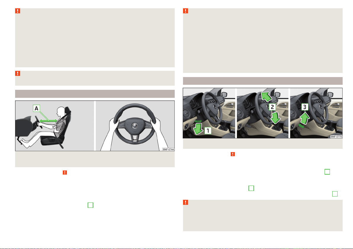
The correct seating position for the driver
Fig. 2
Correct seated position for the driver / correct steering wheel
position
Read and observe on page 9 first.
For your own safety and to reduce the risk of injury in the event of an accident,
the following instructions must be observed.
Adjust the driver's seat so that the pedals can be fully depressed with
slightly bent legs and the distance between the steering wheel and your
chest is at least 25 cm » Fig. 2 -
Adjust the seat backrest so that the highest point of the steering wheel
can be reached with your arms at a slight angle.
Correctly fasten the seat belt » page 12.
A
.
WARNING
■
A distance of least 25 cm to the steering wheel should be maintained,
otherwise the airbag system will not be able to protect you - hazard!
■
When driving, hold the steering wheel with both hands firmly on the outer edge in the “9 o'clock” and “3 o'clock” position » Fig. 2. Never hold the
steering wheel in the “12 o'clock” position or in any other way (e.g. in the
middle, inner edge of the steering wheel or similar). Otherwise, you could
sustain serious injury to the arms, hands and head if the airbag is activated.
■
Ensure there are no objects in the driver's footwell as they may get behind the pedals while driving. You would then no longer be able to operate
the clutch, brake or acceleration pedals.
Adjusting the steering wheel position
Adjusting the steering wheel position
Fig. 3
Read and observe on page 9 first.
The height of the steering wheel can be adjusted.
Turn the safety lever beneath the steering wheel towards the arrow
›
» Fig. 3.
Adjust the steering wheel to the desired position. The steering wheel can be
›
adjusted in line with the arrow 2 .
Press the safety lever down until it clicks into the direction of the arrow 3 .
›
WARNING
■
Never adjust the steering wheel when the vehicle is moving only when
the vehicle is stationary!
■
The safety lever must always be locked so that the steering wheel cannot
accidentally change position – risk of accident!
1
Passive Safety
9
Page 12

Correct seating position for the front passenger
Read and observe on page 9 first.
For passenger safety and to reduce the risk of injury in an accident, the following instructions must be observed.
Position the front passenger seat back as far as possible. The front pas-
senger must maintain a distance of at least 25 cm to the dash panel so
that the airbag offers the greatest possible safety if it is deployed.
Correctly fasten the seat belt » page 12.
WARNING
■
A distance of least 25 cm to the dash panel should be maintained, other-
wise the airbag system will not be able to protect you - hazard!
■
Always keep your feet in the footwell when the car is being driven – never place your feet on the instrument panel, out of the window or on the
surface of the seats! You will be exposed to increased risk of injury if it becomes necessary to apply the brake or in the event of an accident. If an airbag is deployed, you could suffer fatal injuries by adopting an incorrect
seated position!
Correct seating position for the passengers in the rear seats
Read and observe on page 9 first.
For the safety of the passengers in the rear seats, and to reduce the risk of injury in an accident, the following instructions must be observed.
Adjust the head restraint so that the top edge of the head restraint is at
the same level as the upper part of your head.
Correctly fasten the seat belt » page 12.
Seat belts
Using seat belts
Introduction
Seat belts that are fastened correctly offer good protection in the event of an
accident. They reduce the risk of an injury and increase the chance of survival
in the event of a major accident.
The seat belts reduce the kinetic energy (energy of motion) to a considerable
extent. They also prevent uncontrolled movements which, in turn, may well result in severe injuries.
When transporting a child the following instructions must be observed
» page 16, Transporting children safely.
WARNING
■
Fasten seat belts before every ride! This also applies to other passengers -
there is a danger of injury!
■
Maximum seat belt protection is only achieved if you are correctly seated
» page 8, Correct and safe seat position.
■
The seat backrests of the front seats must not be tilted too far to the rear
otherwise the seatbelts can lose their effectiveness.
WARNING
Information on dealing with the safety belts
■
The belt webbing must not be jammed in-between at any point or twis-
ted, or chafe against any sharp edges.
■
Make sure you do not catch the seat belt when closing the door.
WARNING
Information on the proper use of the safety belts
■
No two persons (also not children) should ever use a single seat belt to-
gether.
■
The lock tongue should only be inserted into the lock which is the correct
one for your seat. Wrong use of the safety belt will reduce its capacity to
protect and the risk of injury increases.
10
Safety
Page 13

WARNING (Continued)
■
Many layers of clothing and loose clothing (e. g. a winter coat over a jacket) do not allow you to be correctly seated and impairs proper operation of
the seat belts.
■
Do not use clamps or other objects to adjust seat belts (e.g. for shortening the belts for smaller persons).
■
The seat belts for the rear seats can only fulfil their function reliably when
the seat backrests are correctly locked into position » page 51.
WARNING
Information on the care and maintenance of the safety belts
■
The belt webbing must always be kept clean. Soiled belt webbing may impair proper operation of the inertia reel » page 109.
■
The seat belts must not be removed or changed in any way. Do not attempt to repair the seat belts yourself.
■
Check the condition of all the seat belts on a regular basis. If damage to
the parts of the seat belt system (e.g. the strap, the belt connectors, the retractor, the lock or similar) are detected, the seat belt in question must be
replaced immediately by a specialist.
■
Seat belts which have been subjected to stress in an accident should be
replaced by a specialist garage. The anchorage points for the belts should
also be checked.
Correct routing of seat belt
Read and observe on page 10 first.
It is important that the belt is properly routed to ensure seat belts offer the
maximum protection.
The shoulder belt should be positioned approximately over the middle of your
shoulder (on no account across your neck) and lie flush to the chest » Fig. 4 .
The lower part of the belt should run across the pelvis (it should not lie on top
of the stomach) and must always fit snugly » Fig. 4 - .
For pregnant women, the lower part of the belt must be positioned as low
down as possible across the pelvis, to avoid exerting any pressure on the lower
abdomen » Fig. 4 - .
WARNING
■
Always ensure that the webbing of the seat belts is properly routed. Seat
belts which are not correctly adjusted can themselves cause injuries even in
minor accidents.
■
A seat belt which is hanging too loose can result in injuries as your body is
moved forward by the kinetic energy produced in an accident and is then
suddenly held firm by the belt.
■
The belt webbing must not run across solid or fragile objects (e.g. pencils,
spectacles, pens, keys etc.). Such objects can cause injury.
Fig. 4 Routing of belt webbing over the shoulders and the lap belt /
Routing of belt webbing for an expectant mother
Seat belts
11
Page 14

Fastening and unfastening seat belts
Fig. 5 Fastening / unfastening the seat belt
Read and observe
Before fastening the belt
Adjust the head restraint properly (does not apply to seats with integrated
›
head restraints).
Adjust the seat (applies to the front seats).
›
Fastening
Use the lock tongue to slowly pull the webbing over your chest and pelvis.
›
Insert the lock tongue into the belt buckle » Fig. 5 – that is part of the seat
›
until it clicks into place.
Pull on the belt to check that it has engaged correctly in the lock.
›
Releasing
Grip the lock tongue and press the red button in the buckle » Fig. 5 - , the
›
lock tongue pops out.
Guide the belt back by hand so that the seat belt does not twist and the
›
webbing rolls up fully.
WARNING
The reel opening for the lock tongue must not be blocked otherwise the
lock tongue will not lock into place properly.
on page 10 first.
Inertia reels and belt tensioners
Inertia reels
Each seat belt is equipped with an inertia reel.
When pulling slowly on the seat belt, the belt can move freely. When pulling
sharply on the seat belt, the movement is locked by the inertia reel. The belts
also lock when full braking, when the car accelerates, when driving downhill
and when cornering.
WARNING
If the seat belt does not lock when pulling sharply on it, have it inspected
immediately by a specialist garage.
Belt tensioners
Safety for the driver and front passenger wearing their seat belts is enhanced
by the belt tensioners fitted to the inertia reels of the front three-point seat
belts.
If there is a collision of a certain severity, the seat belts are tightened by the
belt tensioner so that unwanted body motion is prevented.
Belt tensioners are not activated in the event of minor collisions, in the case of
a roll-over and also not in accidents in which no major forces are produced.
WARNING
■
Any work on the belt tensioner system, including the removal and installation of system components because of other repair work, must only be carried out by a specialist garage.
■
If the belt tensioners have been deployed, it is then necessary to replace
the entire system.
Note
■
The belt tensioners can also be deployed if the seat belts are not fastened.
■
Smoke is generated when the belt tensioners are deployed. This is not an in-
dication of a fire in the vehicle.
12
Safety
Page 15

Airbag system
Description of the airbag system
Introduction
The airbag system provides, as a supplement to the seat belts, additional occupant protection during severe frontal and side-on collisions.
The airbag will only provide optimum protection in conjunction with wearing the seat belt - the airbag is not a substitute for the seat belts.
The functional status of the airbag system is indicated by the indicator light
in the instrument cluster » page 29.
System description
Side airbags Head-Thorax - The stress on occupants’ bodies is cushioned
when they make contact with the fully-inflated airbag and the risk of injury to
head and the entire upper body (chest, stomach and pelvis) is reduced on the
side facing the door.
The side air bags can be identified by a label with the lettering marked on
the front seat backrests.
Depending on the vehicle equipment, the airbag system consists of the
following parts.
▶
Individual airbags.
▶
Warning light in the instrument cluster » page 29.
▶
Key switch for the front passenger airbag » page 15.
▶
Warning light for the front passenger airbag in the middle of the dash panel
» page 15.
Airbag deployment
Fig. 6 Airbag installation points
Airbag installation points » Fig. 6
A
Front airbags
B
Front side airbags Head-Thorax
Front airbags - the forward thrust of the driver and of the front passenger is
cushioned when they make contact with the fully-inflated airbag, and the risk
of injury to head and chest is thus reduced.
The front airbags can be identified by the lettering featured on the steering wheel and on the dash panel on the passenger side.
Fig. 7 Inflated airbags
The airbag system is only functional when the ignition is switched on.
When triggered, the airbag fills with gas and unfolds. The inflation of the airbag is carried out in a fraction of a second.
When the airbag inflates, smoke is released. This is not a sign of a fire in the
vehicle.
Airbag system
13
Page 16

Triggering conditions
It is not possible to generally determine which deployment conditions apply to
the airbag system in every situation. The important factors here are the hardness of the object with which the vehicle collides, the angle of impact, vehicle
speed etc.
A decisive factor in the deployment of the airbags is the degree of deceleration at the time. If the vehicle deceleration which occurs and is measured during the collision remains below the prescribed reference values specified in the
control unit, the airbags are not deployed although the vehicle may well suffer
severe damage to the bodywork as a consequence of the accident.
The following airbags will be deployed in the event of a severe frontal
collision.
▶
Driver’s front airbag.
▶
Front passenger airbag.
The following airbags will be deployed in the event of a severe side
collision.
▶
Head-Thorax side airbag on the crash side.
When an airbag is deployed, the following events occur.
▶
The hazard warning lights are switched on.
▶
All doors are unlocked.
▶
The fuel supply to the engine is interrupted.
▶
The interior light comes on (if the automatic operation of the interior light is
switched on - position ).
When there is no air bag deployment?
With minor frontal and side collisions, rear collision, overturning of the vehicle
or vehicle roll-over there is no airbag deployment.
Safety instructions
Fig. 8
Safe distance from the steering
wheel and dash panel
WARNING
General information
■
The seat belts and the airbag system can only offer optimum protection if the driver and passengers are seated properly » page 8.
■
The airbag unleashes enormous force when triggered, which can lead to
serious injuries or fatalities if the driver and passengers are not seated
properly. This applies in particular to children who are transported without
using a suitable child safety seat » page 18.
■
If there is a fault, have the airbag system checked immediately by a specialist garage. Otherwise, there is a risk that the airbag will not be deployed
in the event of an accident.
■
If the airbag has been deployed, the airbag system must then be replaced.
■
The surface of the steering wheel and the dash panel should only be
cleaned with a dry or slightly dampened cloth in the area of the front airbags.
WARNING
Information about the front airbags
■
For the driver and front passenger, it is important to maintain a distance
of at least 25 cm from the steering wheel or the dashboard » Fig. 8 - A. If
you do not keep this distance, the airbag system cannot protect you - hazard! The front seats must always also be correctly adjusted to match the
body size of the occupant.
■
The front passenger airbag must be deactivated if using a rear-facing
child seat on the front passenger seat » page 15, Airbag deactivation. If
this is not done, there is a risk of the child suffering severe or even fatal injuries if the front passenger airbag is deployed.
■
No other persons, animals or objects should be placed in front of the occupants in the front seats in the deployment area of the front airbags.
■
The steering wheel and the surface of the dash panel on the passenger
side must not be stickered, covered or modified in any way. No parts (e.g.
cup holders, mobile phone mounts and the like) may be mounted near the
airbag installation points and in the airbag deployment area.
■
Never place objects on the surface of the dash panel on the passenger
side.
14
Safety
Page 17

WARNING
Information about the side airbags
■
No objects (e.g. sun visors pivoted towards the windows) should be
placed in the deployment area of the side airbag, and no accessories (e.g.
cup holders and the like) should be mounted on the doors - danger of injury!
■
Hang only light clothing on the hooks in the vehicle, do not leave any
heavy or sharp objects in the pockets. Do not use hangers to hang up the
clothes.
■
The airbag system operates using pressure sensors located in the front
doors. For this reason, no adjustments may be carried out to the doors or
door panels (e.g. installation of additional loudspeakers). Further information » page 105.
■
No excessive force, e.g. through blows, kicks etc. should be applied to the
seat backrests - there is a risk of damage to the side airbags. The side airbags would not be deployed in such a case!
■
Any seat or protective covers which you fit to the driver or front passenger seats must only be of a type expressly authorised by ŠKODA AUTO. In
view of the fact that the airbag inflates out of the backrest of the seat, use
of non-approved seat or protective covers would considerably impair the
protective function of the side airbag.
■
Any damage to the original seat covers or stitching at the installation
points for the side airbags should be immediately repaired by a specialist
company.
WARNING
Information on the use of the airbag system
■
Any work on the airbag system, including the installation and removal of
system components due to other repair work (e.g. removal of the steering
wheel), must only be carried out by a specialist garage. Further information
» page 105.
■
No changes of any sort should be made to parts of the airbag system, the
front bumper or the bodywork.
■
Do not manipulate individual parts of the airbag system, as this might result in the airbag being deployed.
Airbag deactivation
Deactivating airbags
The front passenger airbag can be switched off with the key-operated switch
» Fig. 9 on page 15 - .
We recommend that you ask a ŠKODA service partner to deactivate any other
airbags.
A warning light indicates that the airbag has been deactivated » page 29.
Deactivating an airbag should be considered in cases such as the ones
below.
▶
A child seat is mounted on the front passenger seat, in which the child is
transported with its back to the direction of travel » page 16.
▶
Despite correct adjustment of the driver's seat, the distance of at least
25 cm between the middle of the steering wheel and chest cannot be maintained;
▶
Additional controls for drivers with a physical disability are installed in the vehicle.
▶
Special seats (e.g. orthopaedic seats without side airbags) are installed in the
vehicle.
WARNING
If an airbag is deactivated at the time of the vehicle being sold, the purchaser must be informed!
Deactivating the front passenger airbag
Fig. 9
Key-operated switch for the front passenger airbag / warning
light for front passenger airbag
Airbag system
15
Page 18

Key switch positions » Fig. 9 -
The front passenger airbag is activated - after switching on the ignition,
the warning lamp does not light up » Fig. 9 -
The front passenger airbag is deactivated - after switching on the ignition,
the warning lamp lights up
Switch off
Switch off the ignition.
›
Open the passenger door.
›
Fold the key bit out completely for the radio key » .
›
Carefully insert the key into the key slot in the key switch as far as the stop.
›
Use the key to turn the slot of the key switch carefully into the position .
›
Pull the key out of the slot in the key switch » .
›
Close the passenger door.
›
Check that the warning light
›
Switching on
Switch off the ignition.
›
Open the passenger door.
›
Fold the key bit out completely for the radio key » .
›
Carefully insert the key into the key slot in the key switch as far as the stop.
›
Use the key to turn the slot of the key switch carefully into the position .
›
Pull the key out of the slot in the key switch » .
›
Close the passenger door.
›
Check that the warning light
›
switched on.
WARNING
■
The driver is responsible for whether the airbag is switched on or switch-
ed off.
■
Only switch off the airbag when the ignition is switched off! Otherwise a
fault can occur in the system for deactivating the airbag.
■
If the warning light is flashing, the front passenger airbag will not be
deployed in an accident! Have the airbag system checked by a specialist garage immediately.
CAUTION
An insufficiently folded out key bit can damage the key switch!
lights up after the ignition is switched on.
does not light up after the ignition is
Transporting children safely
Child seat
Introduction
To reduce the risk of injury in an accident, children should only be transported
in child seats!
Please refer to the instructions in this Owner's Manual and the child seat manufacturer's instructions with regard to the installation and use of the child seat.
For safety reasons, we recommend that you always transport children on the
rear seats. Only transport a child on the passenger seat in exceptional circumstances.
Child seats complying with the ECE-R 44 Economic Commission for Europe
standard must be used.
Child seats that comply with the ECE-R 44 standard are identified with a test
mark that cannot be removed: a large E within a circle with the test number
below.
WARNING
■
One should never carry children, and also not babies! - on one's lap.
■
When leaving the vehicle, do not leave children unattended in the vehicle.
Children might not be capable of leaving the vehicle or helping themselves
independently in the event of an emergency. Danger to life at very high or
very low temperatures!
■
The child must be secured in the vehicle during the entire journey! Otherwise, the child would be thrown through the vehicle in the event of an accident, causing fatal injuries to both the child and other occupants.
■
Children are exposed to an increased risk of injury in the event of an accident if they lean forward or adopt an incorrect seated position when the
vehicle is moving. This particularly applies to children who are transported
on the front passenger seat as they can suffer severe, or even fatal injuries
if the airbag system is deployed!
16
Safety
Page 19

WARNING (Continued)
■
Pay particular attention to the information provided by the manufacturer
of the child safety seat regarding the correct routing of the belt. Seat belts
which are not correctly adjusted can themselves cause injuries even in minor accidents.
■
Safety belts must be checked to ensure that they are running properly.
One should also ensure that the belt is not damaged by sharp-edged fittings.
■
When installing the child seat on the back seat, the corresponding front
seat must be adjusted so that there is no contact between the front seat
and the child seat or the child being transported in a child seat.
CAUTION
■
When installing a child seat in which the child faces forward, adjust the head
restraints so that they are as high as possible (valid for the rear seats).
■
If the head restraints still prevent the child seat from being installed, even in
the highest position, you will need to remove them (valid for the rear seats)
» page 52. After removing the child seat, refit the head restraints.
Note
We recommend that you use child seats from ŠKODA Original Accessories.
These child seats were developed and also tested for use in ŠKODA vehicles.
They meet the ECE-R 44 standard.
Use of a child seat on the front passenger seat
Does not apply to Taiwan
Warning labels
Fig. 10
Read and observe
Never use a rearward-facing child restraint system on a seat which is protected by an active airbag. This could cause serious injury to the child, or
even death.
This warning is also given on stickers that are located in the following places.
▶
On the passenger sun visor » Fig. 10 - .
▶
On the B-column on the front passenger side » Fig. 10 – .
The following instructions must be followed when using a child seat on the
front passenger seat.
▶
It is essential to deactivate the front passenger airbag if using a child seat in
which the child is transported with its back facing the direction of travel »
▶
If possible, adjust the front passenger seat backrest so that it is as vertical, so
as to ensure secure contact between the passenger seat backrest and the
back of the child seat.
▶
If possible, move the front passenger seat backwards so that there is no contact between the front passenger seat and the child seat behind it.
▶
Set the height-adjustable front passenger seat as high up as possible.
▶
With child safety seats in groups 2 and 3, make sure that the loop-around fittings attached to the child seat headrest is positioned in front of or at the
same height as the loop-around fittings on the B pillar on the passenger side.
and on page 16 first.
.
Transporting children safely
17
Page 20
WARNING
■
Never use a rear-facing child seat on the front passenger seat if the pas-
senger airbag is activated. This child safety seat is positioned in the deployment area of the front passenger airbag. The airbag may cause the child severe, or even fatal injuries, in the event of it being deployed.
■
Once a child seat in which the child is transported with its back to the direction of travel is no longer being used on the passenger seat, the front
passenger airbag should be reactivated.
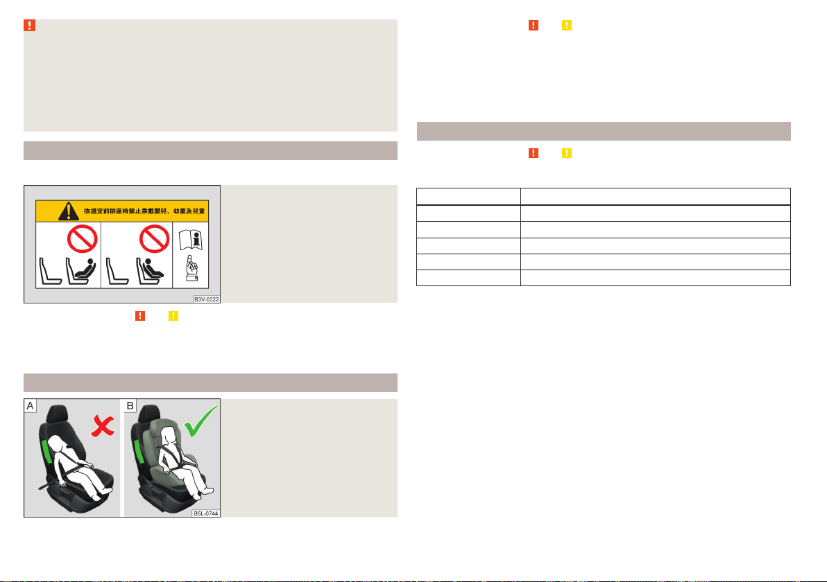
Use of a child seat on the front seat
Applies to Taiwan
Fig. 11
Warning labels
Read and observe and on page 16 first.
No babies, infants or children to be carried on the passenger seat.
A label to this effect can also be found on the passenger's sun visor » Fig. 11.
Child safety and the side airbag
Fig. 12
Incorrect seated position of a
child who is not properly secured – risk from the side airbag / Child properly protected
by safety seat
Read and observe and on page 16 first.
The child must not be positioned in the deployment area of the side airbag
» Fig. 12 - .
There must be sufficient room between the child and the deployment area of
the side airbag that the airbag can provide as much protection as possible
» Fig. 12 – .
Classification of child seats
Read and observe and on page 16 first.
Classification of child seats according to the ECE-R 44 standard.
Group Weight of the child
0 up to 10 kg
0+ up to 13 kg
1 9-18 kg
2 15-25 kg
3 22-36 kg
18
Safety
Page 21

Use of child safety seats which are secured with a safety belt
Never use a rear-facing child seat on the front passenger seat if the passenger airbag is activated. This child safety seat is positioned in the deployment area of
the front passenger airbag. The airbag may cause the child severe, or even fatal injuries, in the event of it being deployed.
Read and observe and on page 16 first.
Overview of the usability of child seats fastened with a seat belt on the different seat types, in accordance with the ECE-R 16 standard.
Group Front passenger seat Rear seats
0
up to 10 kg
0+
up to 13 kg
1
9-18 kg
2
15-25 kg
3
22-36 kg
The seat is suitable for the use of approved child seats in the “Universal”
U
weight group category.
U U
U U
U U
U U
U U
Fastening systems
Attachment points of the
system
Fig. 13
Attachment points of the
system
is a system for securing child seats quickly and safely.
There are two fixing eyes between the seat backrest and the seat cushion of
the rear passenger seat for fixing a child seat with the system » Fig. 13.
WARNING
■
Always refer to the instructions of the manufacturer of the child seat
when installing and removing a child seat with the system.
■
Never attach other child seats, belts or objects to the attachment points
intended for the installation of a child seat with the system – risk of
death!
Note
■
A child seat fitted with the system can only be mounted in a vehicle fit-
ted with a system if the child seat has been approved for this type of vehicle. Further information is available from a ŠKODA Partner.
■
Child seats with the system can be purchased from ŠKODA Original Ac-
cessories.
Transporting children safely
19
Page 22

Use of child safety seats with the system
Never use a rear-facing child seat on the front passenger seat if the passenger airbag is activated. This child safety seat is positioned in the deployment area of
the front passenger airbag. The airbag may cause the child severe, or even fatal injuries, in the event of it being deployed.
Overview of the usability of child seats with the system on the various seat types, in accordance with the ECE-R 16 standard.
Group
0
up to 10 kg
0+
up to 13 kg
Size class of
the child seat
a)
Front passenger seat Rear seats
E X IL-SU
E
X IL-SUD
C
D
B1
C
B
X
IL-SU
IUF
1
9-18 kg
A
2
15-25 kg
3
22-36 kg
a)
The size category is shown on the label attached to the child seat.
- X IL-SU
- X IL-SU
IL-SU The seat is suitable for the use of approved child seats in in the “Semi-Universal”category. The “Semi-Universal” category means that the child
seat with the system is approved for your vehicle. Observe the list of vehicles that comes with the child seat.
IUF The seat is suitable for the use of approved forward facing child seats in the “Universal” weight group category.
X The seat is not fitted with system attachment points.
20
Safety
Page 23

Attachment points of the system
Fig. 14
Attachment points of the
system
is an attachment system that restricts the movement of the upper
part of the child seat.
The attachment points for attaching the belt for a child seat with the
system are located on the back of the rear seat backrests » Fig. 14.
WARNING
■
Always refer to the instructions from the manufacturer of the child seat
when installing and removing a child seat with the system.
■
Only use child seats with the system on the seats with the at-
tachment points.
■
Only ever attach one belt from the child seat to a locking eye.
Transporting children safely
21
Page 24
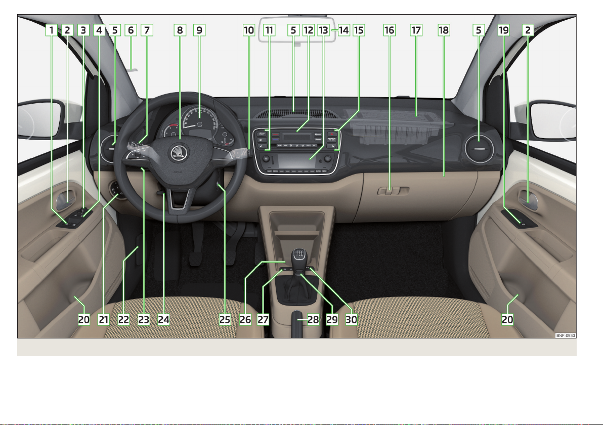
Fig. 15 Cockpit example for LHD models
22
Using the system
Page 25

Using the system
cockpit
Overview
1
Electric windows 41
2
Door opening lever
3
Electric exterior mirror adjustment 49
4
Central locking system 38
5
Air outlet vents 68
6
Parking ticket holder
7
Operating lever (depending on equipment):
▶
Indicator light and high-beam headlight
▶
Speed regulating system 99
8
Steering wheel with horn:
▶
With driver's front airbag
▶
With buttons for radio operation
9
Instrument cluster
10
Operating lever (depending on equipment):
▶
Windscreen wipers and washers
▶
Multifunction display
11
Buttons (depending on equipment):
▶
START-STOP 90
▶
Rear window heater
▶
Seat heater on the front left seat
12
Depending on equipment fitted:
▶
Controls for heating / air conditioning 66
13
Radio
14
Interior rear-view mirror 49
15
Buttons / warning lights (depending on the specification):
▶
Hazard lights
▶
Warning light for the front seat passen-
ger airbag
▶
Seat heating for the front right seat
16
Fold-down hooks 59
17
Front passenger airbag
18
Storage compartment on the front passenger side 58
19
Power window in the front passenger door 41
20
Storage compartment 55
21
Light switch 43
22
Bonnet release lever 114
23
Regulator for headlamp beam adjustment for the headlights 43
24
38
44
13
71
24
48
33
Steering wheel locking lever
25
Ignition lock 90
26
Cup holder 55
27
Buttons (depending on equipment):
▶
City Safe Drive 100
▶
Tyre pressure monitoring 102
28
Handbrake lever
29
Depending on equipment fitted:
▶
Gearshift lever (manual gearbox)
▶
Selector lever (automated gearbox)
30
Depending on specification:
▶
12-volt power outlet
▶
Cigarette lighter
▶
USB input 82
Note
The layout of the controls on right-hand drive vehicles differs partially from
that shown in this layout» Fig. 15.
47
53
69
46
15
53
13
9
92
93
94
57
56
cockpit
23
Page 26

Instruments and warning lights
Instrument cluster
Introduction
Fig. 16 Instrument cluster - Version 1 / Variant 2
Fig. 17
Instrument cluster - Variant 3
1
Speedometer
2
Display » page 31
3
Button:
▶
Switch between the counter for the distance driven (trip) and the odometer » page 32
▶
Reset counter for distance travelled (trip) » page 32
▶
Set the time » page 31
▶
Switch between the outside temperature and time display (only in the
instrument cluster - Variant 3) » page 31
4
Fuel gauge » page 24
5
Engine revolutions counter » page 24
6
Time adjust button » page 31
The instruments are also illuminated when the side light or low beam light is
switched on.
Note
Appears in the display then the system indicates that the ignition is
switched on.
Rev counter
The tachometer 5 » Fig. 17 on page 24 shows the actual engine speed per minute.
The beginning of the red scale range of the tachometer indicates the maximum permitted engine speed of a driven-in and operating warm engine.
You should shift into the next highest gear before the red scale of the revolution counter is reached, or select mode D on the automatic gearbox.
The gear recommendation is important to note in order to maintain the optimum engine speed » page 32.
CAUTION
The rev counter pointer may only move into the red area for a short time - otherwise risk of engine damage!
Fuel gauge- Petrol
Fig. 18
Petrol fuel gauge: Variant 1 / Variant 2 / Variant 3
The display » Fig. 18 only works if the ignition is switched on.
24
Using the system
Page 27
The fuel tank has a capacity of about 35 litres.
When the fuel level goes down to the reserve level A » Fig. 18 in the fuel tank,
the warning light lights up in the display variant 1 and 2 or the symbol flashes in the display variant 3 for 10 seconds together with the remaining segments of the display. There are now about 4 litres of fuel in the tank.
An audible signal sounds as a warning.
WARNING
In order for the vehicle systems to function properly and thus to make driving safe, there must be sufficient fuel in the tank. Never drive until the fuel
tank is completely empty - there is a risk of accidents!
CAUTION
Never drive until the fuel tank is completely empty! Irregular supply of fuel can
cause misfiring, which can result in damage to parts of the engine and the exhaust system.
Note
The arrow next to the symbol within the fuel gauge displays the installation location of the fuel filler on the right side of the vehicle.
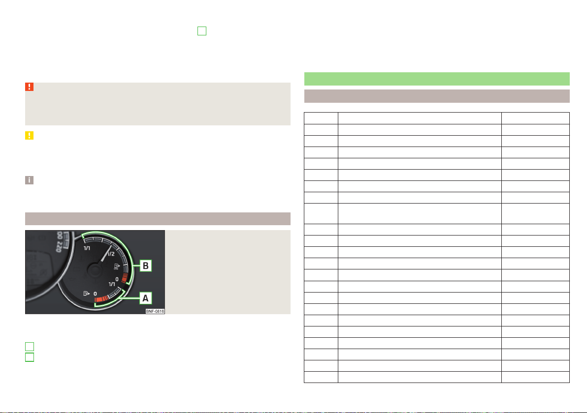
Fuel gauge - petrol / natural gas
Fig. 19
Petrol and natural gas gauge
The display » Fig. 19 only works if the ignition is switched on.
The pointer shows the supply of the of fuel type currently used.
A
Gasoline reserve
B
Natural gas reserve
The capacity of the gasoline fuel tank is approximately 10 litres. The capacity
of the natural gas fuel tank is approximately 11 kg.
If the fuel level in the fuel tank reaches the reserve area for petrol, the warning
light lights up in the display. There are now about 5 litres of fuel in the tank.
If the fuel level in the fuel tank reaches the reserve area for natural gas the
warning light light up in the display. There is now about 1.5 kg of fuel in the
tank.
Warning lights
Introduction
Handbrake » page 26
Brake system » page 26
Front seat belt warning light » page 26
Alternator » page 26
Engine oil pressure » page 26
Coolant » page 27
Automatic gearbox » page 27
Power steering » page 27
Stabilisation control (ESC)
Traction control (ASR)
Antilock brake system (ABS) » page 28
Tyre pressure » page 28
Fuel reserve - petrol » page 29
Fuel reserve - CNG » page 29
Rear fog light » page 29
Exhaust control system » page 29
Engine performance check » page 29
Airbag system » page 29
Handbrake - automatic transmission » page 30
Brake pedal - automatic transmission » page 30
Turning signal system » page 30
Cruise control system » page 30
Main beam » page 30
Rear seat belt warning light » page 30
» page 28
Instruments and warning lights
25
Page 28
City Safe Drive » page 30
START-STOP system » page 30
The warning lights in the instrument cluster indicate the status of certain functions or the presence of faults.
Some warning lights can be accompanied by acoustic signals and messages in
the display of the instrument cluster if required.
After switching on the ignition, some warning lights light up briefly as a function test. If the tested systems are OK, the corresponding warning lights extin-
guishes for a few seconds after switching on the ignition or after starting the
engine.
WARNING
■
Ignoring light-up indicator lamps in the instrument cluster and the control
symbols in the display may cause serious injury or damage to the vehicle.
■
If you have to stop for technical reasons, then park the vehicle at a safe
distance from the traffic, switch off the engine and activate the hazard
warning light system » page 46. Place the warning triangle at the prescribed distance.
■
The engine compartment of your car is a hazardous area. The following
warning instructions must be followed at all times when working in the engine compartment » page 114, Engine compartment.
Handbrake
Read and observe
lights up – the handbrake has been applied.
An audible warning is also given if you drive the vehicle for at least 3 seconds
at a speed of more than 6 km/h.
Braking system
Read and observe on page 26 first.
lights up - the brake fluid level in the brake system is too low or there is an
ABS fault.
▶
Stop the vehicle, switch off the engine, and check the level of the brake fluid
» page 118.
on page 26 first.
WARNING
■
If the warning light lights up at the same time as warning light
» page 28, Anti-lock braking system (ABS), do not continue your
journey! Seek help from a specialist garage.
■
A fault to the ABS system or the braking system can increase the vehi-
cle's braking distance – risk of accident!
Front seat belt warning light
Read and observe on page 26 first.
lights up - the driver or front passenger has not fastened their seat belt.
At a speed of over 20 km/h the warning light flashes and an audible warning
sounds at the same time.
The warning signal is switched of and the indicator light is permanently lit if
the driver and front passenger have not fastened their seat belts within the
next 90 seconds.
Alternator
Read and observe on page 26 first.
lights up – the battery is not being charged whilst the engine is running.
▶
Seek help from a specialist garage.
CAUTION
If, while driving, the warning light lights up in addition to the warning light
» page 27, do not drive any further - risk of damage to the engine!
Switch off the engine and seek assistance from a specialist garage.
Engine oil pressure
Read and observe
lights up or flashes - the engine oil pressure is too low.
An audible signal sounds as a warning.
on page 26 first.
26
Using the system
Page 29

▶
Stop the vehicle, switch off the engine, and check the engine oil level
» page 117, Check and refill.
▶
If the warning light lights up or flashes, do not drive any further, even if the
oil level is correct! Switch off the engine and seek assistance from a specialist garage.
CAUTION
■
The oil pressure light is not an oil level indicator! One should therefore
check the oil level at regular intervals, preferably after every refuelling stop.
■
If for some reason it is not possible to top up the engine oil under the current
circumstances, do not continue driving! Switch off the engine and seek assistance from a specialist garage.
Coolant
Read and observe on page 26 first.
lights up or flashes – the coolant temperature is too high or the coolant lev-
el is too low.
An audible signal sounds as a warning tone.
▶
Stop the vehicle, switch off the engine, and allow the engine to cool down.
▶
Check the coolant level, if necessary top up the coolant.
If the coolant level is within the specified range and the warning light lights
up or flashes again, then there may be a malfunction of the cooling fan.
▶
Switch off the ignition.
▶
Check the fuse for the cooling fan, replace if necessary.
If the coolant level and fan fuse are both OK but the warning light is still
illuminated, do not drive any further!
▶
Seek help from a specialist garage.
Automatic transmission
Read and observe on page 26 first.
fault
lights up - there is a fault in the automatic transmission.
An audible signal sounds as a warning tone.
▶
Do not drive the vehicle! Switch off the engine and seek assistance from
a specialist garage.
Functional impairment
lights up and gear change is not possible - for technical reasons there may
be an impairment of the automatic transmission.
▶
Stop the car, turn the ignition off and on again.
If the warning light lights up after you again switch on the ignition, seek assistance from a specialist garage.
Gearbox overheating
may also light up - the automatic transmission is overheating.
An audible signal sounds as a warning tone.
▶
Stop and allow the transmission to cool down or drive more quickly than
20 km/h (12 mph).
If the warning light lights up again, switch off the vehicle, shut off the engine and allow the gearbox to cool down.
Further information » page 94, Automated transmission.
Power steering
Read and observe on page 26 first.
Fault in the power steering
lights up – this indicates a complete failure of the power steering and the
steering assist is no longer working (significantly higher steering forces).
lights up – this indicates a partial failure of the power steering and the
steering forces can be higher.
▶
Switch off the ignition, start the engine again and travel a short distance.
▶
If the warning light does not go out, obtain assistance from an authorised
dealer.
Disconnecting the vehicle battery
If the vehicle's battery has been disconnected and reconnected, the warning
light comes on after switching on the ignition.
The warning light should go out after driving a short distance.
If, after the motor is restarted and a short drive, the indicator light does not go
out, there is a system error.
Instruments and warning lights
27
Page 30

▶
Seek help from a specialist garage.
Stability control (ESC) / Traction control (TCS)
Read and observe on page 26 first.
flashes – the ESC or TCS is currently active.
lights up – there is an ESC or TCS fault.
▶
Seek help from a specialist garage.
As the ESC operates in conjunction with the ABS, the ESC warning light will
also come on if the ABS system fails.
If the warning light comes on after starting the engine, the ESC or TCS may
have been switched off for technical reasons.
▶
Switch the ignition off and on again.
If the warning light does not illuminate after you switch the engine back on,
the ASR is fully functional again.
Disconnecting the vehicle battery
If the vehicle's battery has been disconnected and reconnected, the warning
light comes on after switching on the ignition.
The warning light should go out after driving a short distance.
If, after a short drive, the indicator light does not go out, there is a system er-
ror.
▶
Seek help from a specialist garage.
More information about the ESC system » page 97, Stability Control (ESC) or
TCS system » page 97, Traction control (TCS).
Anti-lock braking system (ABS)
Read and observe
lights up – there is an ABS fault.
The vehicle will only be braked by the normal brake system without the ABS.
▶
Seek help from a specialist garage.
In the event of an ABS fault, the other braking and stabilization systems are
turned off » page 97, Braking and stabilisation systems .
on page 26 first.
WARNING
■
If the ABS warning light together with the indicator light » page 26,
Braking system lights up, do not continue to drive! Seek help from a
specialist garage.
■
A fault to the ABS system or the braking system can increase the vehi-
cle's braking distance – risk of accident!
Tyre pressure
Read and observe on page 26 first.
Change of tyre pressure values
lights up - there was a pressure change in one of the tyres.
An audible signal sounds as a warning.
▶
Immediately reduce speed and avoid sudden steering and braking manoeuvres.
▶
Stop the vehicle, turn the ignition off and check the tyres and their inflation
pressures » page 122.
▶
Correct the tyre pressure if necessary or replace the affected wheel
» page 126 or use the repair kit » page 129.
▶
Save the tyre pressure values in the system » page 102.
System fault
flashes for approximately 1 minute and remains lit – there may be a fault in
the tyre pressure monitoring system.
▶
Stop the vehicle, turn the ignition off and start the engine again.
If the warning light flashes again after the engine has started, there is a system error.
▶
Seek help from a specialist garage.
Disconnecting the vehicle battery
If the vehicle's battery has been disconnected and reconnected, the warning
light comes on after switching on the ignition.
The warning light should go out after driving a short distance.
If, after a short drive, the indicator light does not go out, there is a system er-
ror.
▶
Seek help from a specialist garage.
28
Using the system
Page 31

Other incidents
The following reasons can explain the warning light being illuminated.
▶
The vehicle is loaded on one side. Distribute the load evenly.
▶
The wheels of one axle are loaded more heavily (e.g. when driving uphill or
downhill).
▶
Snow chains are mounted.
▶
A wheel has been changed.
CAUTION
Under certain circumstances (e.g. sporty style of driving, wintry or unpaved
roads) the warning light in the instrument cluster can be delayed or does
not light up at all.
Fuel reserve - petrol
Read and observe on page 26 first.
lights up – the petrol level in the fuel tank is at the reserve level (approxi-
mately 4-5 litres).
An audible signal sounds as a warning.
▶
Fill up with fuel » page 111.
Fuel reserve - natural gas
Read and observe on page 26 first.
lights up – the natural level in the fuel tank is at the reserve level (approximately 1.5 kg litres).
An audible signal sounds as a warning.
▶
Fill up with fuel » page 112.
Rear fog light
Read and observe
lights up – the rear fog light is switched on.
on page 26 first.
Emission control system
Read and observe on page 26 first.
lights up – there is a fault in the emission control system. The system makes
it possible to drive on in emergency mode - there may be a noticeable reduction in engine performance.
▶
Seek help from a specialist garage.
Engine electronics check
Read and observe on page 26 first.
lights up - there is a fault in the engine management system. The system
makes it possible to drive on in emergency mode - there may be a noticeable
reduction in engine performance.
▶
Seek help from a specialist garage.
Airbag system
Read and observe on page 26 first.
System fault
lights up - there is a fault in the airbag system.
This also applies if the warning light does not come on when the ignition is
switched on.
The functionality of the airbag system is monitored automatically even if one
of the airbags is switched off.
One of the airbags or a belt tensioner has been disabled by the diagnostic
tool
lights up for approximately 4 seconds after the ignition is switched on and
then flashes for approximately 12 seconds.
The front passenger airbag has been disabled with the key switch
lights up for a few seconds when the ignition is switched on.
Below the lettering in the middle of the dashboard, lights
up after switching on the ignition » page 15, Deactivating the front passenger
airbag.
Instruments and warning lights
29
Page 32

WARNING
When a fault in the airbag system occurs, there is a risk of the system not
being triggered in the event of an accident. Therefore, this must be
checked immediately by a specialized garage.
Handbrake - automatic transmission
Read and observe on page 26 first.
lights up or flashes - engage the parking brake.
Further information » page 94, Automated transmission.
Brake pedal - automatic transmission
Read and observe on page 26 first.
lights up – apply the brake.
Further information » page 94, Automated transmission.
Turn signal system
Read and observe on page 26 first.
flashes – the left turn signal is turned on.
flashes – the right turn signal is turned on.
If there is a fault in the turn signal system, the warning light flashes at twice its
normal rate.
When the hazard warning light system is switched on, this will cause all of the
turn signal lights as well as both warning lights to flash.
Cruise control system
Read and observe on page 26 first.
lights up – the vehicle speed is regulated by the cruise control system.
Main beam
Read and observe on page 26 first.
lights up – the main beam or the headlight flasher is switched on.
Rear seat belt warning light
Read and observe on page 26 first.
lights up – a rear seat belt is not fastened.
lights up – a rear seat belt is fastened.
When the seat belt is fastened/unfastened, the particular light lights up briefly
and indicates the current belt status!
City Safe Drive
Read and observe on page 26 first.
flashes quickly - the City Safe Drivesystem is braking the vehicle automati-
cally.
flashes slowly - the system is not available or there is a system malfunction.
If the system is turned off and the vehicle is moving at a speed of about 5-30
km/h, the warning light
If the system is activated again, the warning light
ment cluster display for about 5 s.
Further information » page 100, City Safe Drive.
START-STOPsystem
Read and observe on page 26 first.
lights up - the START-STOPsystem is active.
lights up - the START-STOPsystem is active, but automatic engine cut-off
is not possible.
flashes - the START-STOPsystem is not available.
Further information » page 90, START-STOP system.
lights up in the instrument cluster display.
lights up in the instru-
30
Using the system
Page 33

Information system
Driver information system
Display in the instrument cluster
Fig. 20 Display types: MAXI DOT / Segment displays
Depending on the vehicle's equipment, the information system uses the display in the instrument cluster to provide the following information » Fig. 20.
▶
Time
▶
Counter for distance travelled (trip)
▶
Engaged gear / gear recommendation
▶
Warning lights
▶
Information messages
▶
Service interval display
▶
Multifunction display
▶
External temperature display
▶
Fuel gauge » Fig. 17 on page 24
▶
Door alarm
Door, luggage compartment and bonnet alarm
When the door or luggage compartment / bonnet is open, a graphical warning
appears in theMAXI DOT display. An acoustic signal will also sound if you drive
the vehicle above 6 km/h when a door is open.
Switching between the time and external temperature display
only applies to the segment display (instrument cluster - variant 3).
Hold the key C » Fig. 21 on page 31 until the time / external temperature
›
display flashes.
Release the button.
›
Select the desired indication by pressing briefly.
›
Wait a few seconds until the selected indication stops flashing.
›
Setting the time in the instrument cluster
Buttons in the instrument cluster: Version 1 and 2 / Version 3
Fig. 21
The time can be adjusted with the ignition on.
Instrument cluster - Var. 1 and 2
Press down button A until» Fig. 21the hour flashes in the display.
›
The hour is set by repeatedly pressing button B.
›
Switch to the minutes by pressing button A.
›
The minutes are set by repeatedly pressing button B.
›
Confirm the value entered by pressing button A again, or wait for around 5
›
seconds. The setting is saved automatically (the value stops flashing).
In vehicles equipped with the instrument cluster-Var.1 display, it is also possible to set the
Instrument cluster - Var. 3
Hold the button C » Fig. 21until the time display flashes.
›
Release the button and keep it pressed down until the hour display starts
›
flashing.
Release the button and set the hour by pressing repeatedly.
›
Press and hold the button until the minutes display flashes.
›
Time
in the time menu item » page 35, Menu item
Settings
.
Information system
31
Page 34

Release the button and set the minutes by pressing repeatedly.
›
Keep the button pressed down until the minute indicator stops flashing on
›
the display.
Trip counter
Counter for distance travelled (trip)
Fig. 22
Display » Fig. 22
MAXI DOTdisplay- Counter showing the distance travelled since the last
reset (trip)
Segment display- Counter showing the distance travelled since the last re-
set (trip)
Segment display - Odometer
Choose between the odometer display and the counter showing the
distance driven (trip)
Only applies to vehicles with a segment display.
Press the button B or C » Fig. 21 on page 31.
›
On vehicles with the MAXI DOTdisplay, an indication of the total odometer is
part of the driving data » page 33.
Reset counter for distance travelled (trip)
Select the counter for the distance driven which has been reset (trip) and
›
hold the button B C or » Fig. 21 on page 31.
Recommended gear
Information on the selected gear / Recommended gear
Fig. 23
A suitable engaged gear or, where appropriate, a recommended gear is displayed, with the aim of conserving the life of the engine and increasing driving
efficiency.
For vehicles with automatic transmission the recommended gear will be
shown when the mode for manual gear-changing (Tiptronic) is selected.
Display
MAXI DOT display » Fig. 23
Optimal gear engaged
Gear recommendation (e.g. means that it is advantageous to switch
from 3. to 4. gear)
Segment display » Fig. 23
Optimal gear engaged
Recommended gear
- Recommends that you change up to a higher gear
- Recommends that you change down to a lower gear
Recommended gear (e.g. means that it would be beneficial to change
from 3. gear to a higher gear)
WARNING
The driver is always responsible for selecting the correct gear in different
driving situations (e.g. when overtaking).
32
Using the system
Page 35

Operating the information system
Fig. 24
Buttons on the control lever
Operating the multifunction display
A
Press (up or down) - Select data / Setting values
B
Press Show / confirm entry
Operating the MAXI DOT display
A
Press (up or down) - move to the selected menu
Hold (up or down) - display main menu
B
Press - confirm selected menu item
Driving data (multifunction display)
Introduction
The driving data is displayed in the multifunction display when is ignition is
switched on.
If vehicles with MAXI DOTdisplay do not show the driving data after switching
on the ignition, select the menu item
» page 35, MAXI DOT display.
On vehicles with a MAXI DOT display, there is an option to fade out the units
and some of the information » page 35, Menu item
MFD
in the main menu and confirm
Settings
.
Information overview
Overview of driving data (depending on the vehicle equipment).
Clock - current time is displayed.
Outside temperature - If the outside temperature drops below +4 °C, the
temperature indicator appears and a snowflake symbol (display for low temperature) flashes for a few seconds, then remains displayed together with the
outside temperature.
Driving time - Driving time since last clearing the memory.
Current fuel consumption - When the vehicle is stationary or moving slowly,
the fuel consumption is displayed in l/h (in models in some countries the following appears --,- km/l). With G-TEC vehicles the current consumption of the
fuel currently being used is displayed ( with regards to a stationary or slow
moving vehicle, the natural gas consumption is displayed in kg/h).
Average fuel consumption - Is calculated continuously since the last clearing
of the memory. After erasing the memory, no data will appear for the first 300
m driven. With G-TEC vehicles, the average consumption of fuel currently being used is displayed.
Natural gas quality - The details of the quality of natural gas are displayed as a
percentage of between 70% to 100%. The higher the value of natural gas, the
lower is the consumption.
Range - Drive distance in km which can be covered with the existing tank capacity and with the same driving style. If you drive more efficiently this value
can increase. With G-TEC vehicles the following details are displayed - Range
with natural gas / petrol.
Distance driven - Distance driven since the memory was last cleared.
Total distance travelled - Odometer
Average speed - Value constantly recalculated, for distance since last clearing
the memory. After erasing the memory, no data will appear for the first 300 m
driven.
Current Speed - Digital speedometer.
Coolant temperature - If the coolant temperature is in the range 70-120 °C,
the engine operating temperature has been reached. If the temperature is below 70 ° C, high engine speeds and straining the engine should be avoided. If
the temperature is over 120 ° C, the warning light lights up the instrument
cluster » page 27.
Oil temperature - if the temperature is lower than 50 °C or if there is a fault in
the system for checking the oil temperature, the symbols are displayed.
Warning of excessive speed - It is possible to set a speed limit.
Information system
33
Page 36

WARNING
Even at temperatures of around +4 °C, black ice may still be on the road
surface! You should therefore not only rely on the outside temperature display for accurate information as to whether there is ice on the road.
Warning at excessive speeds
The system offers the possibility to set a speed limit beyond which an acoustic
warning signal will sound and the following warning message (MAXI DOT Display) and the symbol appears in the display of the instrument cluster.
Adjust the speed limit while the vehicle is stationary
Select the menu item
›
Set the desired speed limit.
›
Confirm the set value, or wait several seconds; your settings will be saved
›
automatically.
Adjusting the speed limit while the vehicle is moving
Select the menu item
›
Drive at the desired speed.
›
Confirm the current speed as the speed limit.
›
The set speed limit can be manually adjusted later if needed.
Reset speed limit
Select the menu item
›
By confirming the speed stored in the memory, the speed limit is reset.
›
The set driving mode remains stored even after switching the ignition on and
off. If the break in a journey exceeds 2 hours, the pre-set speed limit is deactivated.
Speed warning at
Speed warning at
Speed warning at
or and confirm.
or and confirm.
or and confirm.
Memory
Fig. 25 Memory display: MAXI DOT display / Segment Display
The system stores data from the two memories described below, which are
then displayed at position A » Fig. 25.
“1” - Single-trip memory
Drive data is stored from when the ignition is switched on to when it is switched off. If the trip is continued within 2 hours after switching off the ignition,
new data will also flow into the calculation of the current driving information.
If the trip is interrupted for more than 2 hours, the memory is automatically
erased.
“2” - Long-term memory
The memory gathers driving information from any number of individual journeys up to a total of 19 hours and 59 minutes driving or 1,999 kilometres driven.
The indicator is automatically set back to zero if one of these two values is exceeded.
To select the preferred memory bank choose the desired specification of
›
the multi-function display and select by repeatedly confirming the preferred
memory bank.
For Deleting the memory for the selected information, hold down the but-
›
ton confirming the specification.
The following drive data is stored in different memory banks.
▶
Average fuel consumption.
▶
Distance driven.
▶
Average speed.
▶
Driving time.
34
Using the system
Page 37

Note
Disconnecting the vehicle battery will delete all memory data.
MAXI DOT display
Introduction
The MAXI DOT display is a user interface which, depending on equipment fitted, provides information about the radio, the multifunction display, the assistance systems etc.
The menus with details can be operated and displayed using the buttons on
the operating lever » page 33.
Main menu points
■
MFD
(Multifunction display) » page 33
■
Audio
» page 35
■
Vehicle status
■
Settings
Note
■
If warning messages are displayed, these messages must be verified to access the main menu.
■
The menu chosen always shifts to one of the higher levels after 10 seconds if
the display is not currently active.
Menu item
The following information is displayed in the
Radio
▶
Currently playing station (name/frequency).
▶
The selected frequency range (e.g. FM) optionally with the number of the
station button (e.g. FM 3), if the station is stored in the memory list.
▶
List of available stations (if more than 5 stations can be received).
▶
TP traffic announcements.
Media
▶
Name of the track being played, if necessary, further information regarding
title (e.g. artist, album name), if this information is stored as a so called ID3
tag on the audio source.
» page 35
» page 35
Audio
Audio
menu item.
Menu item
Vehicle status
Certain functions and conditions of individual vehicle systems are checked
continuously when the ignition is switched on. If there is a system failure, the
relevant message is displayed in the MAXI DOTDisplay, in conjunction with indicator lights, if necessary, indicator light illumination takes place in the instrument cluster » page 25, Warning lights.
The menu item
Vehicle status
is shown in the main menu of the MAXI DOT display whenever there is at least one fault message . After selecting this menu,
the first of the error messages is displayed.
Several error messages are shown on the display under the message e.g. 1/3.
This indicates that the first of a total of three error messages is being displayed.
Menu item
Settings
There is an option to change certain settings using the display. The following
menu items can be selected.
Language
- Setting the language for the texts shown on the display.
MFD data
- Switching on/off certain information of the multifunction display.
Time
- Setting the time, the time format (24 or 12 hour) and the change-over to
summer/winter time.
Units
- Setting the units for temperature, consumption and distance travelled.
Service
- Display the distance travelled and the days until the next service date
» page 35, Service interval display.
Factory setting.
- Resetting the display functions to factory settings.
Service interval display
Introduction
The service interval display shows the kilometres or days until the next service
event.
Information regarding the service intervals » page 106.
Information system
35
Page 38

Prompt in the MAXI DOT display
Before the next service date has been reached, the symbol as well as a mes-
sage about the mileage or days until the next service event appears in the display after switching on the ignition.
At the time of the service, a message appears in the display after switching
on the ignition.
Displaying the distance and days until the next service interval
Messages regarding the kilometres and days until the next service appointment can be displayed any time when the ignition is on, in the
item » page 35, Menu item
Settings
» page 35, Introduction.
service
menu
Prompt in the segment display
Before the next service interval is reached, a key symbol
ing kilometres are indicated on the display for several seconds after switching
on the ignition.
At the time of the service, an acoustic signal will sound and the lettering
appears for a few seconds after switching on the ignition.
and the remain-
Unlocking and opening
Unlocking and locking
Introduction
The vehicle may be equipped with a central locking system which makes it
possible to unlock/lock all doors and the boot lid simultaneously.
The turn signal lights flash twice as confirmation that the vehicle has been un-
locked.
If you unlock the vehicle and do not open a door or the boot lid within the next
30 seconds, the vehicle will lock again automatically.
The turn signal lights flash once as confirmation that the vehicle has been
locked.
If the driver's door has been opened, the vehicle cannot be locked.
If the doors or the luggage compartment lid remain open after the vehicle has
been locked, the turn signal lights do not flash until they have been closed.
Automatic locking / unlocking of a vehicle with central locking system
This function enables the locking of all doors and the boot lid from a speed of
15 km / h. Opening the doors and the boot lid from the outside is not possible.
Renewed automatic unlocking of all doors as well as the luggage compartment
door when removing the ignition key or by opening any of the doors.
WARNING
■
Never leave the key in the vehicle when you exit the vehicle. Unauthorised persons (e.g. children) could lock the car, turn on the ignition or start
the engine - danger of injury and accidents!
■
When leaving the vehicle, never leave persons who are not completely independent, such as children, unattended in the vehicle. These individuals
might not be able to exit the vehicle by themselves or to help themselves.
Can be fatal at very high or very low temperatures!
36
Using the system
Page 39

CAUTION
■
Each key contains electronic components; therefore it must be protected
against moisture and severe shocks.
■
Keep the key grooves clean. Impurities (textile fibres, dust etc.) have a nega-
tive effect on the functionality of the locking cylinder and ignition lock.
Unlock / lock using key and lock
Fig. 26
Left side of the vehicle: Turning
the key for unlocking and locking the vehicle
Read and observe and on page 36 first.
Unlocking/locking the vehicle with the key » Fig. 26
Unlocking the vehicle
Locking the vehicle
Unlocking/locking with the remote control key
Fig. 27
Key with pop-out key bit
Button to unlock the boot lid
A
Button for popping out/pushing in the key bit
B
Battery status warning light - if the warning light does not flash when you
press a button on the key, the battery is discharged.
Unlocking / locking the boot lid
By pressing lightly on the button the lid is unlocked.
By pressing down on the button the lid is unlocked and unlatched (part-
opened).
If the lid is unlocked or released with the button , then the lid is automatical-
ly locked after closing. The period of time after which the flap is locked can be
set » page 40.
CAUTION
■
The remote control may be affected by signal superimposition by transmit-
ters close to the car.
■
The range of the remote control key is about 30 m. The battery must be replaced if the central locking only reacts to the remote control at a distance of
less than 3 m away » page 134.
Vehicle unlocking / locking with the door opening lever
Read and observe and on page 36 first.
Description of the key » Fig. 27
Unlock button
Lock button
Fig. 28 Door opening lever
Read and observe
On vehicles without central locking, you can lock and unlock doors which do
not have a locking cylinder from the inside.
To unlock the door, push the door opening lever in the direction of the ar-
›
row so that the red marking A is visible » Fig. 28.
and on page 36 first.
Unlocking and opening
37
Page 40

To unlock the door pull the door opening lever.
›
Vehicle locking / unlocking with the central locking button
Fig. 29
Central locking button
Read and observe and on page 36 first.
Prerequisites for locking / unlocking with the central locking button
The vehicle is not locked from the outside.
All doors are closed.
To lock, press the button » Fig. 29.
›
To unlock, press the button .
›
The following applies after locking.
▶
Opening the doors and the boot lid from the outside is not possible.
▶
The doors can be unlocked and opened from the inside by a single pull on the
opening lever of the respective door.
WARNING
Doors locked from the inside make it difficult for rescuers to get into the
vehicle in an emergency – risk to life!
SafeLock
Read and observe and on page 36 first.
SafeLock prevents the door from being opened from the inside. This makes an
attempted break-in to the vehicle more difficult.
Activating
SafeLock is activated when the vehicle is locked from the outside.
This function is pointed out by the following message on the display of
the instrument cluster after switching out the ignition.
Activation display
When SafeLock is activated the warning light in the driver's door flashes for 2
seconds in rapid succession, then starts to flash at longer intervals.
Deactivating
The safelock can be switched off by locking twice within 2 seconds.
The warning light in the driver door flashes rapidly for about 2 seconds, then
goes out and starts to flash at longer intervals after about 30 seconds.
If the vehicle is locked and the safe securing system is switched off, the door
can be opened separately from the inside by a single pull on opening lever.
The Safelock system switches back on when the vehicle is locked.
WARNING
If the car is locked and the safe securing system activated, no people must
remain in the car as it will then not be possible to either unlock a door or
open a window from the inside. The locked doors make it more difficult for
rescuers to get into the vehicle in an emergency – risk to life!
Opening/closing a door
Fig. 30 Door handle/door opening lever
Read and observe and on page 36 first.
To open from the outside, unlock the vehicle and pull in the direction of ar-
›
row » Fig. 30 the door handle A.
38
Using the system
Page 41

To open from the inside pull the door opening lever B and push the door
›
away from you.
To the lock from the inside grab handle C and close the door.
›
WARNING
■
The door must be closed properly, otherwise it could open whilst the ve-
hicle is in motion - risk of fatality!
■
Only open and close the door when there is no one in the opening/closing
range – risk of injury!
■
Never drive with the doors open - there is a risk of death!
■
An opened door can close automatically if there is a strong wind or the
vehicle is on an incline – risk of injury!
Child safety lock
Rear door: Child safety lock switch on / off
Fig. 31
Read and observe and on page 36 first.
The child safety lock prevents the rear door from being opened from the inside. The door can only be opened from the outside.
To turn on the child safety lock, turn the vehicle key to position » Fig. 31.
›
To turn off the child safety lock, turn the vehicle key to position .
›
Malfunctions
Read and observe and on page 36 first.
Synchronise remote
If the buttons on the remote control key have been depressed several times
beyond the effective range of the equipment or the battery has been replaced
in the remote control key and the vehicle cannot be unlocked with the remote
control, the key must be synchronised.
Press any button on the remote control key.
›
Unlock the door with the key in the lock cylinder within 1 minute of pressing
›
the button.
Central locking fault
If the warning light in the driver's door initially flashes quickly for around 2 seconds, and then lights up for 30 seconds without interruption before flashing
again slowly, you will need to seek the assistance of a specialist garage.
A failure in the central locking system can lead the vehicle doors and the boot
lid can emergency lock or emergency release » page 134.
Low voltage of the key battery
Replace the battery » page 134.
Luggage compartment lid
Introduction
A
Button
speed of over 9 km/h. The button is reactivated when the vehicle has stopped
and a door is opened.
» Fig. 32 on page 40 is disabled when starting off or driving at a
WARNING
■
Never drive with the luggage compartment lid open or ajar, as otherwise
exhaust gases may get into the interior of the vehicle – risk of poisoning!
■
Ensure that the lock is properly engaged after closing the lid. Otherwise,
the lid might open suddenly while the vehicle is moving, even if the lid was
locked – risk of accident!
Unlocking and opening
39
Page 42

WARNING (Continued)
■
Make sure that when closing the boot lid, no body parts are crushed -
there is danger of injury!
■
Do not press on the rear window when closing the luggage compartment
lid, it could crack – risk of injury!
Opening / closing the boot lid
Opening / closing the boot lid
Fig. 32
Read and observe on page 39 first.
To open the lid, press » Fig. 32 button A in the direction of arrow 1.
›
Raise the lid in the direction of the arrow 2 .
›
To close it, grip recess B and pull in the direction of arrow 3.
›
Delayed locking of the boot lid
Read and observe on page 39 first.
If the boot lid is unlocked with the button on the key, then the boot lid is
automatically locked after closing.
The period after which the boot lid is locked automatically can be extended by
a specialist garage.
CAUTION
There is a risk of unwanted entry into the vehicle before the boot lid is locked
automatically.
Window operation
Introduction
The windows can be operated mechanically by means of the handle attached
to the respective door panel.
The windows can be operated electrically from the following locations; the
front windows from the driver's seat and also via the buttons for the windows
in the passenger door.
WARNING
Always close the window carefully and in a controlled manner. Otherwise
these could cause severe crushing injuries!
CAUTION
■
Keep the windows clean (free of ice and similar) to ensure the correct func-
tionality of the electric windows.
■
Always close the electric windows before disconnecting the battery.
Note
If the windows are open, dust as well as other dirt can get into the vehicle and
in addition the wind noise is more at certain speeds.
Mechanical window openers
Fig. 33 Window operation: left / right
Read and observe and on page 40 first.
To open, turn the crank in the direction of arrow A » Fig. 33.
›
40
Using the system
Page 43

To close, turn the crank in the direction of arrow B.
›
Electric windows
Fig. 34 Buttons for window levers
Read and observe and on page 40 first.
The electrical power windows can only be operated when the ignition is
switched on.
The windows in the front doors can be operated from the driving position. The
front passenger window is operated using the button in the passenger door.
Power window buttons » Fig. 34
A
Front door left
B
Front door right
To open, press down the appropriate button until the window has moved in-
›
to the desired position.
To
close it, pull gently on the top edge of the button until the window has
›
moved into the desired position.
Manually opening/closing rear windows
Fig. 35 Opening/closing rear windows
Read and observe and on page 40 first.
To open, grasp the safety catch in recess A» Fig. 35.
›
Open the window in the direction of arrow 1 and lock it by pressing down
›
the safety catch in the direction of arrow 2 to the stop.
To close, grasp the safety catch in recess A.
›
Pull the safety catch in the opposite direction to arrow 2 and pull the win-
›
dow back to its starting position in the opposite direction to 1 until the
safety catch clicks into place.
Panoramic tilt / slide sunroof
Introduction
The panoramic tilt / slide sunroof (hereinafter referred to as tilt / slide sunroof)
can only be operated when the ignition is turned on and when the outdoor
temperature is above -20 °C.
WARNING
When operating the tilt/slide sunroof and the sunshade, proceed with caution to avoid causing crushing injuries – risk of injury!
Unlocking and opening
41
Page 44

CAUTION
■
During the winter it may be necessary to remove any ice and snow in the vicinity of the sliding/tilting roof before opening it to prevent any damage to the
opening mechanism.
■
Always close the sliding/tilting roof before disconnecting the battery.
Operation
Fig. 36 Operation of the sliding/tilting roof
Read and observe and on page 41 first.
The sun roof can be operated with the rotary switch.
Operation of the sliding/tilting roof » Fig. 36
Open fully
Open to the low-noise position
A
Open partially
Close completely
1
Opening (switch in position )
2
Closing (switch in position )
After turning the switch one stop to position (spring-tensioned position),
the tilt / slide sunroof stops in the position in which the intensity of the wind
noise is low. After turning the switch further to position , the tilt / slide sunroof opens up to the stop.
Force limiter
Read and observe and on page 41 first.
The sliding/tilting roof is fitted with a force limiter.
If there is an obstacle, the closing process is stopped and the glass pane re-
tracts by several centimetres.
WARNING
If the tilt / slide sunroof is closed, by pulling on the recess of the switch in
the direction of arrow 2, » Fig. 36 on page 42 and the closing process is
hindered by an obstacle, then at the third attempt at closing, the force limitation will cease to function (if less than 5 s passes between the individual
attempts to close). The tilt / slide sunroof closes with full force - this can
cause injury.
Activate operation of the tilt / slide sunroof
Read and observe and on page 41 first.
If the tilt / slide sunroof stops working (e.g. after disconnecting and connecting the battery), then the operation must be reactivated.
Turn on the ignition and set the switch to position » Fig. 36 on page 42.
›
Press the switch on the recess E down and pull forwards.
›
The tilt / slide sunroof opens and closes again after around 10 seconds.
Release the lever.
›
42
Using the system
Page 45

Manually operated sunblind
Lights and visibility
Fig. 37
Operation of the sunblind
Read and observe and on page 41 first.
To open, pull the handle in the direction of arrow A » Fig. 37.
›
To close, pull the handle in the direction of arrow B.
›
Light
Introduction
Unless otherwise stated, the lights only work when the ignition is on.
WARNING
For safety reasons, always set the the light switch to the position as
the default setting.
■
The automatic driving lamp control only operates as a support and
does not release the driver from his responsibility to check the lights and, if
necessary, to switch on the light depending on the prevailing light conditions.
Note
The headlights may mist up temporarily. When the light is on, the light-emitting surface demists after a short time.
Operation of the light function
Fig. 38
Light switch and control dial for
the headlight range control
Read and observe on page 43 first.
To switch the light function on / off, switch A » Fig. 38 should be turned to
one of the following positions.
Switching off lights (except daytime running lights)
Switching lights on/off automatically » page 45
Lights and visibility
43
Page 46

Switch on daytime running lights and side lights or parking lights
» page 46
Turn on the low beam
Depending on the vehicle load, adjust the headlight range by turning the controller B » Fig. 38 to the following positions.
Front seats occupied, boot empty
All seats occupied, boot empty
All seats occupied, boot loaded
Driver seat occupied, boot loaded
WARNING
Always adjust the headlight beam to meet the following conditions - otherwise risk of accident.
■
The vehicle does not dazzle other road users, especially oncoming vehi-
cles.
■
The beam range is sufficient for safe driving.
Note
If the light switch is in the position , the ignition key is removed and the driver's door is open, an audible warning signal will sound. After a few seconds or
after closing the driver's door, the audible alarm switches off, but the parking
lights will remain switched on.
Daytime running lights (DAY LIGHT)
Read and observe on page 43 first.
The daytime running lights light up the area in front of and to the rear of the
vehicle (only applicable for some countries).
The daytime running lights are switched on automatically if the following
conditions are met.
The ignition is switched on.
The lights switch is in position , or .
The light switch is in position and the fog lights are turned on, the daytime
running lights will turn off.
WARNING
Always switch on the low beam when visibility is poor.
Turn signal and main beam
Fig. 39
Operating lever: Turn signal and
main beam operation
Read and observe
Control stalk positions » Fig. 39
Switch on right turn signal
Switch on left turn signal
Switch on main beam (spring-tensioned position)
Switching off main beam / switching on headlamp flasher (spring-loaded
position)
The main beam can only be switched on when the low beam lights are on.
The headlight flasher can be operated even if the ignition is switched off.
The turn signal switches off automatically, depending on the steering angle af-
ter completing the turn.
Comfort flashing
When the operating lever is pressed lightly up or down, the indicator in question flashes three times.
WARNING
Only turn on the main beam or the headlight flasher if other road users will
not be dazzled.
Note
An acoustic warning signal will sound when the driver's door is opened if the
lever is not in the middle position after removing the ignition key from the ignition lock. The acoustic warning signal will stop just as soon as the driver's door
is closed.
on page 43 first.
44
Using the system
Page 47

Automatic driving light control
Fog lights/rear fog light
Fig. 40
Light switch: AUTO position
Read and observe on page 43 first.
The light switch is in position
the automatic switch on / off the lights corresponding to the light or weather
conditions (rain) takes place.
Automatic driving light control during rain
The daytime running lights are switched on automatically if the following conditions are met.
The light switch is in the position
The windscreen wipers are on for more than 15 s.
The light turns off automatically about 4 minutes after turning off the wipers.
CAUTION
Poorer visibility is evaluated by a sensor mounted below the windscreen in the
holder of the rear-view mirror. Do not cover the sensor - the system function
can be disrupted.
» Fig. 40 then depending on the equipment
.
Fig. 41
Light switch - switch on front
and rear fog light
Read and observe
Switching on the fog lights / rear fog lights is possible if the following conditions apply.
The light switch is in position
To turn on the fog lights pull the light switch to position 1, the indicator
›
light will light up in the light switch.
To turn on the rear fog light, pull the light switch to position 2, the indica-
›
tor light will light up in the instrument cluster.
If the vehicle is not fitted with fog lights, the rear fog light is switched on by
pulling out the light switch to the only possible setting.
The fog lights/rear fog light are switched off in the reverse order.
on page 43 first.
,
or » Fig. 41.
Fog lights with CORNER function
Read and observe on page 43 first.
The CORNER function automatically switches on the fog lights on the respective side of the vehicle (e.g. when cornering), if the following conditions are
fulfilled.
The turn signal is switched on or the front wheels are turned sharply 1).
The vehicle speed is below 40 km/h.
The dipped beam is switched on.
The fog lights are not switched on.
1)
If the two switch-on variants are conflicting (e.g. if the front wheels are turned to the left and the right turn
signal light is switched on), the turn signal light has the higher priority.
Lights and visibility
45
Page 48

The two fog lights are switched on when you shift into the reverse gear.
COMING HOME / LEAVING HOME
Read and observe on page 43 first.
The function COMING HOME ensures that the vehicle's environment is illuminated after switching off the ignition and opening the driver's door.
The function LEAVING HOME ensures that the vehicle's environment is illuminated after unlocking the vehicle with the radio remote control unit.
The function switches the light on only if there is poorer visibility and the light
switch is in the position .
Switching on the COMING HOME function
Switch off the ignition and press the control lever briefly to position
›
» page 44.
After closing the door or the boot lid, the light remains on for another 15 s.
CAUTION
■
Poorer visibility is evaluated by a sensor mounted below the windscreen in
the holder of the rear-view mirror. Do not cover the sensor - the system function can be disrupted.
■
If this option is always enabled, then the battery is heavily loaded.
Hazard warning light system
Fig. 42
Button for hazard warning light
system
Read and observe on page 43 first.
To switch on/off, press the button» Fig. 42.
›
When first switched on, the turn signal lights and the warning light buttons
all flash at the same time as the warning lights in the instrument cluster.
The hazard warning light system can also be operated if the ignition is switched off.
If one of the airbags is deployed, the hazard warning light system will switch
on automatically.
Parking light
Read and observe on page 43 first.
The side light is provided for lighting of the parked vehicle.
Switching on the parking light on one side
Switch off the ignition.
›
Press the control lever all the way into position or until it stops» Fig. 39
›
on page 44.
The parking light is turned on on the relevant side of the vehicle.
Switching on the side light on both sides
Turn the light switch to position » page 43 and lock the vehicle. The side
›
lights are switched on.
After pulling out the ignition key and opening the driver's door, an audible
warning sounds. After a few seconds or after closing the driver's door, the audible warning is turned off.
CAUTION
Turning on the parking light means the battery is heavily loaded.
Driving abroad
Read and observe
When driving in countries with opposing traffic system (traffic on the
left/right), your headlights may dazzle oncoming traffic. Therefore, it is necessary to have the headlights adapted by a specialist garage.
on page 43 first.
46
Using the system
Page 49

Interior lighting
Visibility
Introduction
The inner lighting also works if the ignition is switched off. With the ignition
switched off, the lights will automatically switch off after approximately after
10 minutes.
Interior light
Fig. 43
Interior lighting: Version 1/version 2
Positions for light switch A » Fig. 43
Switching on
Automatic operation (centre position)
Switching off
Switch on / off (by pressing the relevant switch
Reading lamp left
Reading lamp right
Automatic operation - position
The system is turned on when any of the following is present.
▶
The vehicle is unlocked.
▶
One of the doors is opened.
▶
The ignition key is removed.
The system is turned off when any of the following is present.
▶
The vehicle is locked.
▶
The ignition is switched on.
▶
About 30 seconds after all the doors have been closed.
B
) » Fig. 43
Introduction
WARNING
No objects should be attached to the sun visor that could restrict the view
or endanger the vehicle occupants during sudden braking or in a collision.
Rear window heater
Fig. 44
Button for rear window heater
Read and observe on page 47 first.
The heater allows rapid defrosting and ventilation of the rear window.
The heating only works when the engine is running.
To switch the heating on / off, press button » Fig. 44.
›
When the heater is switched on, a lamp illuminates inside the button.
The heating switches off automatically after approximately 10 minutes.
Note
If the on-board voltage decreases, the heating switches off automatically
» page 119, Automatic shutdown of consumers - vehicle battery discharge
protection.
Lights and visibility
47
Page 50

Front sun visors
Fig. 45 Fold down visor / Pivot driver/passenger visor sideways
Read and observe on page 47 first.
Operation and description of the sun visor » Fig. 45
1
Swivel cover towards the windscreen
2
Swivel cover towards the door
A
Parking ticket band (if part of the specification)
B
Vanity mirror
Note
A vanity mirror can be installed in either the driver's or the front passenger's
sun visor.
Windscreen wipers and washers
Introduction
The windscreen wipers and the windscreen washer system only operate if the
ignition is switched on.
WARNING
Do not use the windscreen washer system at low temperatures, without
heating the windscreen beforehand. The window washer fluid could other-
wise freeze on the windscreen and restrict the view to the front.
CAUTION
■
If the windscreen wipers are in the switched-off position, they cannot be
raised off the windscreen. Before collapsing the wipers, the wipers must be
set to the service position » page 135.
■
In cold temperatures and during the winter, check before switching on the
ignition that the wiper blades are not frozen to the windscreen. If the windscreen wipers are switched on when the blades are frozen to the windscreen,
this may damage the blades and windscreen wiper motor!
■
Carefully separate frozen windscreen wiper blades from the windscreen and
free from snow and ice.
■
Handle the windscreen wipers with care - there is a risk of damage to the
windscreen by the windscreen wiper arms.
■
Do not switch on the ignition when the wiper arm is raised from the windscreen - there is a risk of damage to the bonnet by the wiper arms.
■
If there is an obstacle on the windscreen, the wipers will try to push away the
obstacle. The wipers then stop to prevent themselves from being damaged.
Only switch the wipers on again after the obstacle has been removed.
Front wipers and washers
Fig. 46
Operating the front windscreen
wipers and washer system
Read and observe and on page 48 first.
The lever can be moved to the following positions » Fig. 46
High-speed wiping
Slow-speed wiping
Depending on equipment fitted:
▶
Automatic windscreen wiping in the rain
▶
Intermittent wiping
Wipers and washers off
Single wipe of the windscreen (spring-loaded position)
48
Using the system
Page 51

A
Setting windscreen wiper interval for position (by setting the switch in
the direction of the arrow, the windscreen wipers will wipe more often)
Spraying and wiping the disc (spring-loaded position) - after releasing the
operating lever the wipers continue for another 1 to 3 strokes
Rear wipers and washer
Fig. 47
Operation of the rear wiper and
washer system
Read and observe and on page 48 first.
The lever can be moved to the following positions » Fig. 47
Spraying and wiping the disc (spring-loaded position) - after releasing the
operating lever the wipers continue for another 1 to 3 strokes.
Rear screen wiping
Wipers and washers off
Note
The rear window is wiped once automatically if the windscreen wipers are on
when reverse gear is selected.
Interior mirror dimming
Read and observe on page 49 first.
Mirror positions » Fig. 48
A
Basic mirror position (not darkened)
B
Mirror blackout
Exterior mirrors
Fig. 48
Mirror positions
Rear view mirror
Introduction
WARNING
Exterior mirrors increase the field of view, however, they make objects appear smaller and further away. Therefore use the interior mirror whenever
possible, for assessing the distances to the vehicles following behind.
Fig. 49 Exterior mirror operation: mechanical / electrical
Read and observe on page 49 first.
The outer mirror surfaces are (depending on the vehicle specification) mechanically or electrically adjustable.
To set the mirror surface, move the knob in the direction of arrows » Fig. 49.
›
If the electrical mirror setting fails at any time, the mirrors can be adjusted by
hand by carefully pressing on the edge of the mirror surface.
Lights and visibility
49
Page 52

The knob for the electrically adjustable mirrors can be moved to the following
positions » Fig. 49 - .
Adjust the left-hand exterior mirror
Switch off mirror control
Adjust the right-hand exterior mirror
Exterior mirror heater (only operates when the engine is running)
Folding in the exterior mirrors
The mirror can be manually folded in towards the side window. To put it back
into its original position, it should be folded back from the side window until it
audibly clicks into place.
WARNING
Do not touch the exterior mirror surfaces, if the exterior mirror heating is
switched on - hazard of burning.
Seats and head restraints
Front seats
Introduction
WARNING
■
Only adjust the driver's seat when the vehicle is stationary – otherwise
risk of accident!
■
Caution when adjusting the seat! You may suffer injuries or bruises as a
result of adjusting the seat without paying proper attention.
Adjusting the front seats
Fig. 50
Controls on the left front seat
Read and observe on page 50 first.
The seats can be adjusted by the pulling or pressing the operating element in
the direction of the arrows» Fig. 50.
A
Adjusting the seat in the longitudinal direction (after releasing the control
lever, locking must be audible)
B
Adjusting the seat height
C
Adjusting the tilt of the backrest (do not lean on the backrest when adjusting)
D
Adjust the tilt of the seat back (seats with Easy Entry System)
Some controls are arranged in mirror image formation on the passenger seat.
Fold forward and slide seat using the Easy Entry System
Pull lever D » Fig. 50 and fold the seat backrest forwards.
›
At the same time, move the seat forwards.
›
50
Using the system
Page 53

Restore position of the seat with Easy Entry System
Push the seat backwards again to its original position.
›
Fold the seat backrest back. The locking mechanism must audibly snap into
›
place.
Check this by pulling on the seat backrest.
›
Note
After a certain time, play can develop within the adjustment mechanism of the
backrest angle.
Folding front passenger seat
Fig. 51
Folding the front passenger seat
forward
Read and observe on page 50 first.
The front passenger seat can, depending on specification, be folded forward
into a horizontal position.
To fold the seat down, pull the lever in the direction of arrow 1 and fold
›
down the seat back in the direction of arrow
nism must audibly snap into place.
Slide the seat forwards up to the stop.
›
To fold back, pull the lever in the direction of arrow 1 pull and fold back the
›
seat back in the direction of arrow 2. The locking mechanism must audibly
snap into place.
Move the seat all the way back to the stop (depending on the specification,
›
the seat may resume the forward position it previously had).
2
» Fig. 51. The locking mecha-
WARNING
■
If the seat backrest is folded, passengers may only be transported on the
outer seat behind the driver.
■
The front passenger airbag should be switched off when transporting ob-
jects on the seat backrest that has been folded forwards » page 15.
■
Do not adjust the seat back while driving - danger of injury and accidents!
■
When moving the seat backrest, keep limbs out of the area between the
seat and seat backrest – risk of injury!
■
Never transport the following items on the seat backrest when folded
forwards.
■
Objects that could restrict the driver's view.
■
Objects which make it impossible for the driver to control the vehicle
(e.g. if they roll under the pedals, or protrude into the driver's zone).
■
Objects which could lead to injury to passengers (e.g. if accelerating
sharply, braking or changing direction).
Rear seat backrests
Fig. 52 Fold down seat backrest / pull on belt for side trim panel
Folding forward
Press the release handle A in the direction of arrow 1 and tilt » Fig. 52 the
›
seat backrest in the direction of arrow 2.
Remove or push the head restraints all the way down » page 52 and fold
›
the seat backrest forward in the direction of arrow 2.
A
For all-in-one seat backrests, press the release handles
seat backrest at the same time.
on both sides of the
Seats and head restraints
51
Page 54

Folding backwards
If the head restraints had been removed, they should be reinserted with the
›
backrest slightly raised» page 52.
Pull the seat belt C for the side panel in the direction of arrow 3 » Fig. 52.
›
Raise the seat backrest against the direction of arrow 2 until the release
›
handle A audibly locks. Check this by pulling on the seat backrest.
Make sure that the red marker B is not visible.
›
For all-in-one seat backs, pull the two seat belts towards the side panel. After
folding back the seat back, the release handles A should audibly click into
place on both sides of the seat back and the red mark B should not be visible
on either side of the seat back.
WARNING
■
The seat backs in occupied rear seats must be properly engaged.
■
When transporting objects in the luggage compartment that has been enlarged by folding the backrest forward, ensure the safety of the passenger
being transported on the other rear seat.
■
The seat backrests must be securely locked in position so that no objects
in the luggage compartment can slide into the passenger compartment on
sudden braking – risk of injury.
Only the front headrests are height-adjustable.
Grasp the headrest and move upwards in the direction of arrow 1 » Fig. 53.
›
To move the headrest down, press the securing button A in the direction of
›
arrow 2 and hold it down while pressing the headrest in the direction of arrow 3.
Note
The front headrests are integrated into the seat backrests and cannot be adjusted in height.
Removing/inserting
CAUTION
When moving the seat backrest the seat belts should not be trapped - there is
a risk of damage to the seat belts.
Headrests
Setting the height
Fig. 53
Setting the height of the back headrest
52
Using the system
Removing/inserting the rear headrests
Fig. 54
Only the rear headrests can be removed or installed.
Before removing/fitting the headrests, fold the corresponding seat backrest
›
slightly forward » page 51.
To remove the headrest, pull it out of the seat backrest as far as the stop.
›
Hold down the securing button
›
time insert the vehicle key in opening B in the direction of arrow 2 and remove the headrest in the direction of arrow 3 » Fig. 54.
To insert the headrest, push the headrest into the seat backrest in the direc-
›
tion of arrow
4
until the locking button clicks into place.
A
in the direction of arrow 1, at the same
Page 55

Front seat heating
Fig. 55
Buttons for heating the front
seats
The seat backrests and seats can be heated electrically.
Seat heating buttons » Fig. 55
Left seat heating
Right seat heating
To turn on the heater at maximum heat (level 2) press button or .
›
By repeatedly pressing the button, the heat is turned down until it is completely switched off. The level of the seat heating is indicated by the number of illuminated warning lights in the switch.
The seat heating only operates when the engine is running.
WARNING
If you are sensitive to pain and/or temperature, e.g. through medication, paralysis or because of chronic illness (e.g. diabetes), we recommend not to
use the seat heating. If the seat heating is used, we recommend to make
regular breaks in your journey when driving long distances, so that the body
can recuperate from the stress of the journey. Please consult your doctor,
who can evaluate your specific condition.
Note
If the on-board voltage decreases, the seat heating switches off automatically
» page 119, Automatic shutdown of consumers - vehicle battery discharge
protection.
CAUTION
The following instructions should be observed to avoid damage to the seats.
■
Do not kneel on the seats or otherwise apply concentrated pressure to them.
■
Do not switch on the heating for unoccupied seats.
■
Do not switch on the heating for seats which have objects on them (e.g. a
child seat, bag or similar).
■
Do not switch on the heating for seats which have seat covers or protective
covers on them.
Seats and head restraints
53
Page 56

Useful features
Ticket holder
Interior fittings
Introduction
WARNING
■
Do not place anything on the dash panel. These objects might slide or fall
down when driving and may distract you from concentrating on the traffic
– risk of accident!
■
Make sure that while driving no objects can enter the driver's footwell they could cause an accident!
■
Do not carry any objects on the front passenger seat except objects designed for this purpose (e.g. child seat) – risk of accident!
■
No objects should be placed in the storage compartments nor in the
drinks holders; the vehicle occupants could be endangered if there is sudden braking or the vehicle collides with something.
■
For safety reasons, lockable storage compartments should be closed
while driving - there is a risk of injury from the opened lid or through the
loose objects in the compartment.
■
Make sure no objects protrude from the storage compartments - danger
of injury!
■
Do not exceed the permissible loads for the storage compartments and
pockets - risk of injury and risk of damage to the compartments and pockets!
■
Ash, cigarettes, cigars and the like should only be stored in the ashtray danger of fire/burns!
■
The storage compartments, multimedia holder and waste container are
not a substitute for the ashtray and must not be used for such purposes –
risk of fire!
CAUTION
Do not place any large or sharp objects in the storage compartments and
pockets - there is a risk of damage to the compartments and pockets.
Fig. 56
Ticket holder
Read and observe and on page 54 first.
The ticket holder» Fig. 56 is provided for the holding and displaying e.g. car
park tickets.
Storage compartment on the driver's side
Fig. 57
Storage compartment on the
driver's side
Read and observe and on page 54 first.
The open stowage compartment A can be found underneath the dash panel
on the driver's side » Fig. 57.
54
Using the system
Page 57

Stowage compartments in the doors
Cup holders
Fig. 58 Storage compartments: in the front door/in the rear door
Read and observe and on page 54 first.
Storage compartments » Fig. 58
A
Storage compartment
B
Bottle holder with a capacity of max. 1.5 l
WARNING
The storage compartment A » Fig. 58 is to be used exclusively for storing
objects which do not stick out - danger of restricting the effectiveness of
the side airbags.
Storage compartments in the front centre console
Fig. 59
Storage compartments
Read and observe and on page 54 first.
The open storage compartments A can be found in the front centre console
» Fig. 59.
Fig. 60 Cup holder in the front
Fig. 61
Rear cup holder
Read and observe and on page 54 first.
The cup holders are located in the centre console at the front » Fig. 60 and at
the rear A » Fig. 61.
to
Fixing a beverage container in the holder forward open the holder in di-
›
rection of arrow » Fig. 60.
Place the cup into the cup holder so that the cup holder clip surrounds the
›
cup securely.
WARNING
■
Do not use any cups or beakers which are made of brittle material (e.g.
glass, porcelain). This could lead to injuries in the event of an accident.
■
Never put hot cups in the cup holders. If the vehicle moves, they may spill
– risk of scalding!
Useful features
55
Page 58

CAUTION
Do not leave open beverage containers in the cup holders during the journey.
There is a risk of spilling e.g. when braking which may cause damage to the
electrical components or seat upholstery.
Waste container
Fig. 62
Waste container: inserting and moving/opening
Fig. 63
Replace bags
Read and observe and on page 54 first.
The waste container can be inserted into the slots in the doors.
Insert waste container
Position the waste container at the front edge of the slot.
›
Push the waste container to the back in the direction of the arrow
›
» Fig. 62.
Push the waste container as required in the direction of arrow B.
›
A
Remove the waste container
Remove the waste container in the opposite direction to the arrow
›
» Fig. 62.
Open/close waste container
Lift the lid in the direction of arrow C » Fig. 62.
›
Closing takes place in reverse order.
Replace bags
Remove the waste container from the slot.
›
Press the two locking lugs on the frame in the direction of arrow 1» Fig. 63.
›
Pull the bag together with the frame down in the direction of arrow 2.
›
Remove the bag from the frame.
›
Pull the new bag through the frame and pull it over the frame in the direction
›
of arrow
Place the bag with the frame in the direction of arrow 4 into the container
›
body, so that the two lugs engage audibly on the frame.
We recommend that you use 20x30 cm bags.
Cigarette lighter
To use the lighter, push it in as far as the stop and wait until the glowing
›
lighter clicks out again » Fig. 64.
Take out the glowing lighter instantly, use it and insert it back into the sock-
›
et.
3
.
Note
Fig. 64
Cigarette lighter
Read and observe and on page 54 first.
A
56
Using the system
Page 59

WARNING
Be careful when using the cigarette lighter - can cause burns.
Note
■
The cigarette lighter operates only if the ignition is switched on.
■
The cigarette lighter socket can also be used as a 12 volt socket.
Ashtray
Fig. 65
Removing the ashtray
Read and observe and on page 54 first.
The ashtray can be used for disposing of ash, cigarettes, cigars and the like.
Grasp the ashtray (not by the lid) and remove » Fig. 65 it in the direction of
›
the arrow.
Insertion takes place in reverse order.
WARNING
Never place hot or flammable objects in the ashtray – risk of fire!
12-volt socket
Fig. 66
12-volt socket
Read and observe and on page 54 first.
To use, open the cover of the socket and insert the lead of the electrical ap-
›
pliance in the socket » Fig. 66.
The 12-volt socket will only work when the ignition is switched on.
WARNING
■
Do not place anything on the dash panel. These objects might slide or fall
down when driving and may distract you from concentrating on the traffic
– risk of accident!
■
Make sure that while driving no objects can enter the driver's footwell they could cause an accident!
■
Stow all devices safely during the journey to prevent them from being
thrown around the interior in the event of a sudden braking manoeuvre or
an accident – risk of death!
■
The devices may warm up during operation – risk of injury or fire!
■
Improper use of the power sockets and the electrical accessories can
cause fires, burns and other serious injuries.
CAUTION
■
The sockets can only be used for the connection of approved electrical ac-
cessories with a total power consumption of up to 120 watts - otherwise the
electrical system of the vehicle may be damaged.
■
Connecting appliances when the engine is not running will drain the vehicle's
battery!
■
Switch off the device connected to the power socket before you switch the
ignition on or off and before starting the engine - danger of damage caused by
voltage fluctuations.
Useful features
57
Page 60

Multimedia holder
Fig. 67
Multimedia holder
Read and observe and on page 54 first.
The multimedia holder » Fig. 67 is provided for storing mobile phones, MP3
players and the like.
Storage compartment on the front passenger side - version 1
Fig. 68
Storage compartment on the
front passenger side
Read and observe and on page 54 first.
The open stowage compartment A can be found underneath the dash panel
on the front passenger's side » Fig. 68.
There is a bag hook B in the stowage compartment which is used to hang
smaller items of luggage (e.g. bags, or similar).
The maximum permissible load on the hook is 1.5 kg.
Storage compartment on the passenger side - version 2
Fig. 69 Open storage compartment / interior of the storage compartment
Read and observe and on page 54 first.
Storage compartment » Fig. 69
A
Opening lever
B
Glasses storage box
C
Notepad holder
D
Pen holder
E
Card holder
F
Coin holder
Open/close
If there is a folding hook » Fig. 71 on page 59on the handle A » Fig. 69, re-
›
move any items hanging from it.
To open, pull the opening lever A in the direction of arrow 1. The cover
›
folds in the arrow direction 2.
To close, screw in the lid in the opposite direction of arrow 2 until it audibly
›
clicks into place.
58
Using the system
Page 61

Storage compartment for umbrella
Fig. 70
Storage compartment for the
umbrella
Read and observe
The storage compartment under the passenger seat » Fig. 70is used for storing an umbrella.
CAUTION
Never store a wet umbrella in the storage compartment - there is a risk of
damage to the umbrella.
Note
We recommend that you use the umbrella from the ŠKODA Original Accessories.
and on page 54 first.
Foldable hook
Fig. 71
Fold down hook
To use it, pull down the hook in the direction of the arrow » Fig. 71.
›
The maximum permissible load on the hook is 1.5 kg.
Note
When the hook is folded forward, it folds back automatically when the storage
compartment is opened.
Clothes hook
Fig. 72
Clothes hooks
Read and observe and on page 54 first.
The clothes hooks are located on the centre door bars of the vehicle » Fig. 72.
The maximum permissible load of each of the hooks is 2 kg.
WARNING
■
Never leave any heavy or sharp-edged objects in the pockets of the items
of clothing hung up - danger of injury.
■
Do not use hangers to hang up the clothes - there is a risk of restricting
the effectiveness of head airbags and a danger of injury from the hanger.
■
Make sure that any clothes hanging from the hooks do not impede your
vision.
Read and observe and on page 54 first.
The folding hook is intended to be used for holding small items of luggage (e.g.
bags or similar).
Useful features
59
Page 62

Storage pockets on the inner sides of the front seats
Fig. 73
Storage pocket
Read and observe and on page 54 first.
The storage pockets are located on the inside of the front seats » Fig. 73 and
are used to store small and light objects (e.g. mobile phones).
The maximum permissible load for each of the pockets is 150 g.
Stowage compartments in front of the rear seats
Fig. 74
Storage compartment
Read and observe and on page 54 first.
The open storage compartments A are located on the backs of the front
seats » Fig. 74.
The maximum permissible load of the compartment is 200 g.
WARNING
Never work with the device when driving –There is a risk of accident!
CAUTION
■
Never exceed the maximum permissible load of the bracket- there is a risk of
damage or functional impairment.
■
Make sure that no liquid or moisture gets into the opening for the fixture -
There is a risk of damage to the vehicle’s electrical system.
■
Use a dry cloth to clean the adapter and the bracket.
Fasten bracket to the adapter
Fig. 75 Insert bracket into the adapter / remove bracket from the
adapter
Read and observe and on page 60 first.
to Fixing the bracket to the adapterinsert the bracketA into the supports
›
B
in direction of arrow 1until it clicks » Fig. 75.
To remove the holder from the adapter press the lever C in direction of
›
arrow 2 press and remove the bracket A in direction of arrow 3.
Phone bracket
Introduction
In the telephone bracket, a telephone (or similar device) which is 122x56 mm
to 164x83 mm can be transversely mounted.
60
Using the system
Page 63

Attach adapter to the panel
Inserting / removing phone
Fig. 76 Remove cover/ attach adapter / remove adapter
Read and observe and on page 60 first.
Attach adapter
For example, insert a coin into the openingA and lift up cover in direction of
›
arrow 1 » Fig. 76.
Insert the adapter into the opening in the panel and push in the direction of
›
arrow 2 until it clicks.
Remove adapter
Push the release buttonB in the direction of arrow 3 and remove the
›
adapter in the direction of arrow 4» Fig. 76.
Seal the opening in the dashboard with the cover.
›
WARNING
An incorrectly mounted adapter can break loose from the dashboard in
sudden manoeuvre or an accident - there is risk of injury!
Fig. 77 Inserting phone / Removing phone
Read and observe and on page 60 first.
Inserting phone
Insert the phone between the arms Amove them in the direction of arrows
›
1
and secure the phone by doing so » Fig. 77.
Secure the phone by moving the arm B in direction of arrow 2.
›
Removing phone
Press The key C in direction of arrow 3 the arm B moves into the starting
›
position in the direction of arrow 4 » Fig. 77.
Remove the phone from the bracket.
›
To adjust the lower arms to the starting position, lift the holder with the
›
adapter of the panel and press the button D.
Useful features
61
Page 64

Transport of cargo
Luggage compartment and transporting objects
Introduction
When transporting heavy objects, the driving characteristics change due to
the shift in centre-of-gravity. The speed and style of driving must be adjusted
accordingly.
When transporting cargo the following instructions must be adhered to
▶
Distribute the load evenly in the luggage compartment and secure it with
suitable lashing straps to the lashing eyes or fixing nets so that they cannot
slip.
▶
Place heavy objects as far forward as possible.
▶
Tyre pressure should be adjusted for the load.
In the event of an accident, even small and light objects gain so much kinetic
energy that they can cause severe injuries.
The magnitude of the kinetic energy is dependent on the speed at which the
vehicle is travelling and the weight of the object.
Luggage compartment light
The light switches on/off when the luggage compartment lid is opened or
closed.
If the boot lid is open and the ignition switched off, the light will go out automatically after 10 minutes.
WARNING
■
Never exceed the maximum permissible load of the respective fasteners,
nets, hooks etc. If heavy objects have not been suitably secured, there is a
risk of injury!
■
Do not exceed the permissible axle loads and permissible gross weight of
the vehicle – risk of accident!
■
An unsecured dirt or improperly attached load could slip during a sudden
manoeuvre or in an accident - danger of injury!
WARNING (Continued)
■
Loose cargo could hit a deployed airbag and injure occupants – danger of
death!
■
When transporting loads in the luggage compartment that has been enlarged by folding one of the rear seats forward, care should be taken to ensure the safety of passengers transported on the other rear seat.
CAUTION
■
Never exceed the maximum permissible load for the respective fasteners,
nets, hooks etc. - these could be damaged.
■
Please ensure that the heating elements for the rear window heater are not
damaged as a result of abrasive objects.
■
Do not place any sharp objects in the nets in the luggage compartment -
there is a risk of damage to the nets.
Fasteners
Fig. 78
Fasteners
Read and observe and on page 62 first.
The fasteners are located on both sides of the luggage compartment.
Overview of the fastening elements » Fig. 78
A
Fasteners only for fastening fixing nets
B
Hooks for hanging small items of luggage (e.g. bags)
C
Lashing eye for fastening the load
B
The maximum static load for each hook
eyes C is 350 kg.
is 1.5 kg and the individual lashing
62
Using the system
Page 65

WARNING
Do not use hook B » Fig. 78 to lash down any objects - there is a risk of
damage to the hook during sudden braking or a vehicle collision.
Fixing nets
Fig. 79
Example of how to fix nets/fastening details for the rear area of
the luggage compartment
Fig. 80 Details of the fastening behind the rear seats
Read and observe and on page 62 first.
Fastening examples for nets » Fig. 79 and » Fig. 80
cross bags
Fastening details in the rear area of the luggage compartment
Details of the fastening to the upper lashing eyes behind the foldable rear
seat rest
Details of the fastening to the lashing eyes on the luggage compartment
floor behind the rear seats
The maximum permissible load for each of the nets is 1.5 kg.
Luggage compartment cover
Fig. 81
Remove the luggage compartment cover
Read and observe and on page 62 first.
If the support straps A » Fig. 81 are attached to the boot lid, then opening the
lid will raise the boot lid cover (hereafter referred to as cover).
Fold up and lock
Raise the cover and bolt it down » Fig. 81 on both sides of the boot lid in the
›
studs B.
Unlocking
Fold the raised cover down. The cover is released from the studs B » Fig. 81.
›
Removal
On both sides of the boot lid unhook the straps A in the direction of arrow
›
1
» Fig. 81.
Press down on both sides on the underside of the cover to free them from
›
the studs C.
Take out the cover in the direction of arrow 2.
›
Inserting
Position the fixtures D on the cover over the studs C » Fig. 81.
›
Transport of cargo
63
Page 66

Press down on both sides on the top of the cover in the area of the studs C.
›
The fixtures D must lock into place in the studs C on both sides of the luggage compartment.
On both sides of the boot lid unhook the straps A.
›
WARNING
■
Do not place any objects on the cover during the trip - risk of injury if
braking suddenly or colliding!
■
Never ride with the cover up - risk of damage to the cover.
Variable loading floor
Fig. 82
Variable loading floor in the raised position: raise / raised
To lower it, lift the loading floor, push it into the grooves in the direction of
›
arrow 2 insert and lay it on the luggage compartment floor in direction of
arrow 3.
Class N1 vehicles
Read and observe and on page 62 first.
In class N1 vehicles that are not fitted with a protective grille, a lashing set that
complies with the EN 12195 standard (1-4) must be used for fastening the
load.
For safe vehicle operation, the proper functioning of the electrical installation
is essential. It is important to ensure that it is not damaged in adaptation as
well as the loading and unloading of the cargo space.
Transportation on the roof rack
Fig. 84 Attachment points - 3-door
Fig. 83
Variable loading floor: lower / lowered
Read and observe and on page 62 first.
To raise the loading floor, grasp handle A and raise as far as the stop in the
›
direction of arrow 1 » Fig. 82.
64
Using the system
Fig. 85 Attachment points - 5-door
Page 67

The attachment points A and B are located on both sides of the vehicle
» Fig. 84 and » Fig. 85.
The basic carrier should be mounted and dismounted in accordance with the
instructions provided.
Roof load
The maximum permitted weight of the load incl. carriers is 50 kg.
WARNING
The following instructions must be observed to aid road safety when transporting cargo on the roof rack.
■
Always distribute the load on the roof rack evenly and secure properly
with suitable lashing straps or tensioning straps.
■
When transporting heavy objects or objects which take up a large area on
the roof rack system, the handling of the car may change as a result of the
displacement of the centre of gravity. The style of driving and speed must
therefore be adapted to the current circumstances.
■
The permissible roof load, permissible axle loads and permissible total vehicle weight must not be exceeded under any circumstances – risk of accident!
CAUTION
■
Make sure that the panoramic tilt / slide sunroof or the boot lid does not col-
lide with the roof load when opened.
■
Ensure the roof aerial is not impaired by the load being transported.
Note
We recommend that you use a roof rack from ŠKODA Original Accessories.
Heating and ventilation
Heating, manual air conditioning system, Climatronic
Introduction
The heater heats and ventilates the vehicle interior. The air conditioning system also cools and dehumidifies the vehicle interior.
The heating effect is dependent upon the coolant temperature, thus full heat
output only occurs when the engine has reached its operating temperature.
The cooling system works under the following conditions.
The cooling system is switched on.
The engine is running.
The outside temperature is above 2 °C.
The blower is switched on.
When the cooling system is switched on, it prevents misting of the windscreen
and windows.
It is possible to boost the effectiveness of the cooling system by briefly activating the air recirculation system» page 68.
Health protection
To reduce health risks (e.g. common colds), the following instructions for the
use of the cooling system are to be observed.
▶
The difference between the outside temperature and the inside temperature
should not be greater than 5 °C.
▶
The cooling system should be turned off about 10 minutes before the end of
the journey.
▶
Once a year, a disinfection of the air conditioner is to be carried out by a specialist company.
WARNING
■
The blower should always be on to prevent the windows from misting.
Otherwise there is a risk of accident.
■
Under certain circumstances, air at a temperature of about 5 °C can flow
out of the vents when the cooling system is switched on.
Heating and ventilation
65
Page 68

Note
■
The air inlet in front of the windscreen must be free of e.g. ice, snow or
leaves to ensure that the heating and cooling system operates properly.
■
After switching on the cooling Condensation from the evaporator of the air
conditioning may drip down and form a puddle below the vehicle. This is not a
leak!
■
If the coolant temperature is too high, the cooling system is switched off to
ensure that the engine cools down.
Heating and manual air conditioning
Heating Controls
Fig. 86
A
Setting temperature
▶
Reduce the temperature / Increase the temperature
B
Setting the fan speed (level 0: blower off, level 4: highest speed)
C
Set the direction of the air outlet » page 68
Air flow to the windows
Air flow to the upper body
Air flow to the footwell
Air flow to the windows and the footwell
D
Recirculated air mode
▶
Switch on
▶
Switch off
Switching the cooling system on/off
Information on the cooling system
After pressing the button
the indicator light on the button lights up, even if
not all the conditions for the cooling system have been met. The cooling system starts to work as soon as the following conditions have been met
» page 65.
Note
In order to ensure adequate warmth and comfort, the operation of the air conditioning may lead to an increase in the engine idle speed.
Fig. 87 Controls of the air conditioning
Read and observe on page 65 first.
Individual functions can be set or switched on by turning the control dial and
pressing the appropriate button » Fig. 86 and » Fig. 87. When the function is
switched on, the indicator light in the button lights up.
66
Using the system
Page 69

Climatronic (automatic air conditioning)
Fig. 88 Controls the Climatronic
Read and observe on page 65 first.
Individual functions can be set or switched on by pressing the corresponding
button » Fig. 88. When this function is switched on, the corresponding icon appears in the display.
1
Setting temperature
▶
Increase the temperature / Reduce the temperature
2
Selected temperature
3
Temperature units (degrees Celsius / Fahrenheit)
4
Intensive air flow to the windscreen switched on
5
Recirculated air mode activated
6
Direction of air flow
7
Automatic operation of the air conditioning system is switched on
8
Cooling system activated
9
Set blower speed
Adjust the blower speed
10
▶
Increase speed
▶
Reduce speed up to switching off the Climatronic
11
Interior temperature sensor
Switching on/off the intensive windscreen air flow - when this function
is switched on, the warning light illuminates in the button
Switch recirculation on/off » page 68
Switching the airflow to the windows on and off
Switching the airflow to the upper body on and off
Switching the airflow to the footwell on and off
Switching automatic mode on
Switching the cooling system on/off
After the cooling system is switched off, only the ventilation function remains
active whereby the minimum temperature that can be reached is the outside
temperature.
Setting temperature
In the range between 16 °C to 29 °C, an automatic temperature control takes
place.
At a temperature setting below 16 ° C, lights up in the temperature display,
the Climatronic functions with maximum cooling performance.
At a temperature setting above 29 °C, lights up in the temperature display,
the Climatronic functions with maximum heating output.
CAUTION
Do not cover the interior temperature sensor 11 » Fig. 88 - the function of the
Climatronic could be affected.
Note
In order to ensure adequate thermal comfort, there may be an increase in engine idle speed during operation of the Climatronic in some circumstances.
Climatronic - automatic operation
Read and observe on page 65 first.
The automatic mode is used in order to maintain a constant temperature and
to demist the windows in the interior of the car.
To switch on press the button. The display shows (pos. 7 » Fig. 88
›
on page 67).
To turn off, press any button for the air distribution or change the blower
›
speed. However, temperature regulation is continued.
Heating and ventilation
67
Page 70

Recirculation
Read and observe on page 65 first.
The recirculation mode prevents contaminated outside air getting into the interior of the vehicle. In recirculated air mode air is sucked out of the interior of
the vehicle and then fed back into the interior.
To the turn on move the slider D into position or press the button in
›
Climatronic.
To turn off move the slider D into position or press the button in Cli-
›
matronic.
WARNING
The recirculation system cannot be switched on for a longer period of time,
because no fresh air is fed through from the outside. “Stale air” may result
in fatigue in the driver and occupants, reduce attention levels and also
cause the windows to mist up. As soon as windows mist up, turn on the recirculation system immediately - risk of accident!
CAUTION
We recommend not smoking in the vehicle when the recirculating air operation is switched on. The smoke sucked from the interior is deposited on the
evaporator of the air conditioner. This produces a permanent odour when the
air conditioning system is operating which can only be eliminated through considerable effort and expense (replacement of compressor).
Air outlet vents
Air outlet vents
Fig. 89
Read and observe on page 65 first.
The direction of airflow can be adjusted for the air vents 3 » Fig. 89 and the
vents can also be opened and closed individually.
To open, press on the outer edge of the slat in area A » Fig. 89.
›
To close, move the slats back to their original position.
›
To change the air flow, turn the slats in the desired direction.
›
Depending on the setting for air distribution, the air will flow from the following air vents.
Set the direction of the air
outlet
1, 2, 3
3, 4
3, 5
1, 2, 3, 5
CAUTION
Do not cover the air vents - the air distribution could be compromised.
Air outlet vents » Fig. 89
68
Using the system
Page 71

Infotainment
Swing/ Blues Radio
Important notes
Introduction
The information contained in this section refer to Swing and Blues radio, unless it is indicated otherwise.
WARNING
■
Adjust the volume to ensure that acoustic signals from outside the vehicle, e.g. the police, ambulances and fire engines, can be heard at all times.
■
High volumes can cause hearing damage.
Note
In some countries, some unit features can no longer be selected when the vehicle is running faster than a certain speed. This is not a malfunction, but complies with the national legal regulations.
Mobile phones and applications
Fig. 90
QR code with reference to web
pages for checking the compatibility of devices
Read and observe on page 69 first.
The availability of some of the functions described in this Owner's Manual
depends on the type of device to be connected and the applications installed in it.
Mobile phones
On the ŠKODApages, check to see if the device is compatible with the selected mobile phones. This verification is done by reading the QR code » Fig. 90
by the associated application in the external device (e.g. phone, tablet) or after
typing the following address into the web browser.
http://go.skoda.eu/compatibility
Due to the large number of mobile phones as well as the ongoing development
of these devices, ŠKODA AUTO cannot always ensure compatibility with the
device unconditionally. It is always recommended to physically check function
on the associated vehicle, including the ŠKODA Partners, beforehand.
Only those versions of the selected phones will be tested and supported which
originate from the official distribution network. The same also applies to their
firmware and software.
The functions of the mobile phone to be tested may differ from the same type
of mobile phone depending on the specification for the respective country or
the specific service.
Mobile phones with the operating system and in the version available at the
time of these tests will be tested. In this regard, it could be the case that the
functions of a mobile phone may differ with a different operating system version compared to the one used with the tested phone.
ŠKODA AUTO can accept no responsibility for the continuous changes made
by the mobile phone manufacturers and application vendors.
ŠKODA AUTO does not accept any liability for any damage to the device or
vehicle due to the use of incorrect or illegal applications or the improper or unauthorized use of mobile phones.
Applications
Due to the variety of applications and communication systems as well as their
ongoing development, the available applications may not work in all external
devices. ŠKODA AUTO can accept no liability for their proper function.
Applications, their use and the required data connection may be chargeable.
The range of available applications and their functionality is dependent on the
device, vehicle and region.
The function of mobile applications can be influenced by the quality of the In-
ternet connection.
Swing/ Blues Radio
69
Page 72

Some applications are dependent on the availability of services that are provided by third parties.
Unit overview and operation
Device Description - Swing
Device overview: Swing
Fig. 91
Left control dial for switching the device on and off; volume adjustment
Control dial for calls and confirmations
1
SD card slot
2
Colour contact-less display
3
AUX input
4
- Radio menu » page 76
5
- Media menu » page 79
6
Function buttons (current button function is shown in the display above
each button)
7
- Telephone menu » page 83
8
- Device settings » page 73
Device Description - Blues
Fig. 92 Device overview: Blues
Left control dial for switching the device on and off; volume adjustment
Control dial for calls and confirmations
1
SD card slot
2
Black and white contact-less display
3
AUX input
4
- Radio menu » page 76
5
- Media menu » page 79
6
Function buttons (current button function is shown in the display above
each button)
7
- Return to the higher-level menu
8
- Device settings » page 75
9
CD slot
Buttons for rewind / fast forward
CD-eject button
Sound settings » page 75
70
Infotainment
Operation using the buttons on the device
Operation Action
Selecting menu/menu item/func-
tion
Confirming menu/menu
item/function
Turning the knob .
Press the wheel
Page 73

Operation Action
Applies to Swing: By pressing the func-
Returning to higher-level menu
Applies to Blues: By pressing
tion button
- Selected menu item / function value
Select the menu item / function
value
- Deselected menu item / function val-
ue
- Selected menu item / function value
Set value
Turning the knob .
Pressing the function button or
Operation using the multifunction steering wheel
Fig. 93
Buttons/dial on the multifunction steering wheel
The radio, media and the phone can be operated using the multifunction steering wheel.
To operate the phone via the multifunction steering wheel, the telephone and
the device must be paired » page 84.
Phone menu
Button/dial
» Fig. 93
Press Accept a call/end a call
Hold
A
Action Function
Reject a call/Last number dialled/
Switch call to telephone and back (during a
call)
Turn Volume setting
Radio menu
But-
ton/dial
Action Function
» Fig. 93
A
A
Press
Press Switch sound off/on
Turn Volume setting
Skip to next station/to a station stored under
the preset buttons
Hold Search forwards
Press
Go to previous station/to a station stored un-
der the preset buttons
Hold Search backwards
Media menu
But-
ton/dial
Action Function
» Fig. 93
A
A
Press Switch sound off/on
Turn Volume setting
Press Skip to next track
Hold Fast forward
Press Switch to previous track
Hold Fast rewind
Note
The devices connected to the AUX input can not be operated with the buttons/dials on the multifunction steering wheel.
Swing/ Blues Radio
71
Page 74

Display areas
Fig. 94
Display areas:
Swing/Blues
Fig. 95
Display areas:
Swing
Description of display » Fig. 94 and » Fig. 95
A
Status line with time and outdoor temperature data and other information
B
Information on the current menu
C
Current menu functions
D
Menu item with “Checkbox”
▶
- Function is switched on
▶
- Function is switched off
E
Open a submenu
F
Scroll symbol- motion is achieved by turning the dial
Automatic Power On of the device
If the device was not turned switched off using the button before the ignition was turned off, this will automatically switch on after the ignition has been
switched on.
Automatic Power Off of the device
If the vehicle key is pulled out of the ignition lock while the unit is switched on,
the device will switch off automatically.
With the ignition off, the device will automatically turn off after about 30 minutes.
The device turns off automatically under certain circumstances. The device informs of this via a text message on the device display.
Restart the device
If the device does not respond (if it “freezes”) This can be restarted by holding for longer than 10 s.
Adjust volume
To increase the volume, turn the controller clockwise.
›
To reduce volume, turn the controller anticlockwise up to mute.
›
If, at the time of muting, sound is played from the source in the media menu,
then the playback is interrupted (pause)1).
CAUTION
■
High volumes can cause sound resonance in the vehicle.
■
When changing or connecting an audio source, this may cause sudden
changes in volume. Reduce the volume before changing or connecting an audio source.
Power on / off
To power on/off the device, press .
›
1)
Does not apply to AUX.
72
Infotainment
Page 75

Device Settings - Swing
Main menu settings
Fig. 96
Main menu settings
Press the button
›
Choose the desired menu item by turning the dial Orby pressing the func-
›
.
tion button or .
Confirm the menu item selection by pressing the controller Orby pressing
›
the function button .
Settings for the Phone menu » page 73
Sound settings » page 73
Device settings » page 73
Settings for the Radio menu » page 74
Media menu settings » page 75
Operating theŠKODA Move & Funapplication » page 88
Phone menu settings
Press the button
›
■
Hands-free
is displayed during a call)
■
Select telephone
lect telephone
■
User profile
■
Delete favourites
■
Mailbox no.: ...
■
List contacts by: ...
■
Surname
■
Forename
■
Import contacts: …
→ .
- Switching a call to the phone / back to the device (the menu item
- Search for available telephones/list of paired telephones/se-
- user profile settings
- Management of preferred contacts (favourites)
- Enter the mailbox phone number
- Arrangement of telephone contact list
- Sort by contact name
- Sort by contact's first name
- Import telephone contacts
■
Remember your mobile
- Turn on/off the warning message in the device display before forgetting the phone in the vehicle (if the phone was connected
to the device)
■
Select ringtone
- Selection of the device’s own ringtone (using the ringtone is
dependent on the model of phone connected)
Sound settings
Press the button
›
■
Volume
- Volume settings
■
Maximum switch-on volume
device
■
Announcements
■
Speed adjustment
■
Entertainment fading (parking)
with activated parking aid
■
AUX volume: ...
■
Quiet
- low volume
■
Medium
■
Loud
- High volume
■
Bluetooth audio: …
audio profile of the connected external device
■
Quiet
- low volume
■
Medium
■
Loud
- High volume
■
navigation announcements
for the ŠKODA Move & Funapplication
■
Balance - Fader
(applies to equipment with four speakers)
■
Balance
- Setting the sound focus between the left and right (applies to equip-
ment with two speakers)
■
Bass - Mid - Treble
→ .
- Sets the maximum volume after switching on the
- Adjustment of traffic announcements volume (TP)
- increases the volume as speed increases
- Lowers the audio volume (e.g. radio volume)
- Sets the volume for the device connected via AUX
- Medium volume
- Volume setting of the device connected via Bluetooth
- Medium volume
- Volume adjustment of navigation announcements
- Setting the sound focus between left and right, front and rear
- setting the equaliser
System settings
Press the button
›
Menus for the system settings
■
Screen
- setting the screen displays
■
Language
■
- set the device language
Bluetooth
- Bluetooth® device settings
→ .
®
Swing/ Blues Radio
73
Page 76

■
App connection
■
Remove source safely
■
Factory settings
■
System information
■
Copyright
- Turn the connection on / off with the Move & Funapplication
- Safe removal of external devices
- reset to factory settings
- System Information
- license information of the device
Display settings
▶
Press the button
■
Switch off screen (in 10 s)
→ →
screen
.
- Enable / disable the automatic display shut-off func-
tion
■
Brightness: ...
■
Show clock in standby mode
- Adjusts the brightness of the display
- Time and date shown on the display when the igni-
tion is switched on and the unit is switched off
■
Colour: …
- Colour selection for the display representation
Settings the device language
▶
Press the button
▶
Set the desired language.
By selecting the menu item
→ →
Language
.
automatically (same as instrum. cluster)
the device language is set according to the language setting for the MAXI DOTdisplay
» page 35.
Bluetooth settings
▶
Press the button
■
Bluetooth
■
- Switch on/off Bluetooth® function
Visibility: …
→ →
Bluetooth
.
- switch on/off the visibility of the Bluetooth® device for other devi-
ces
■
System name: …
- Bluetooth® device name (Skoda BT XXXXwhere XXXX repre-
sents the last four digits of the vehicle identification number)
■
Paired devices
■
Find devices
■
Bluetooth audio (A2DP/AVRCP)
- display the list of paired Bluetooth ® devices
- searches for available devices
- Turn on/off the ability to connect an audio de-
vice (e.g. MP3 player, tablet etc.)
Connection with the application
▶
Press the button
■
Data transfer active
→ →
App connection
.
- Turn the connection on / off with the Move & Funapplica-
tion
Safe removal of the external device
▶
Press the button
▶
Select the external device to be removed.
→ →
Remove source safely
.
Factory settings (to factory settings)
▶
Press the button
▶
Select the menu item to be reset to factory settings.
By selecting the menu item
→ →
Reset all
Factory settings
.
, all device menus are reset to factory set-
tings.
System information
▶
Press the button
■
Part number: - Part number of the device
■
Software: - Version of the software used
■
Hardware: - Version of the hardware used
■
Bluetooth: - Version of the Bluetooth® software used
▶
to Update device software press the function button .
→ →
System information
.
The information about available software updates with a ŠKODA partner.
Radio settings
Press the button
›
■
Arrow buttons: …
■
Presets
- Change between stations stored under the preset buttons
■
Stations
range
■
Traffic programme (TP)
■
Radio text
off
■
Delete stored stations
■
FM station list: …
radio range
■
Alphabetically
■
By group
■
Advanced FM settings
■
RDS Regional: …
stronger reception signal
■
Automatic
■
Fix
- Turn off the automatic change
→ .
- Setting the station change function (function keys and )
- Change between all available stations of the selected broadcasting
- Switches TP traffic programme on/off
- Switching the text display radio (valid only for FM and DAB) on and
- Delete the preset buttons
- Sort the channels in the list of available stations on the FM
- Sorting by name
- Sorting by PI code
- Additional FM broadcast range settings
- Setting the automatic change to a regional stations with a
- Switching on the automatic change
74
Infotainment
Page 77

■
Radio Data System (RDS)
- enable/disable RDS function (receiving additional in-
formation from the station)
■
Automatic frequency control (AF)
- Search for alternative frequencies of the sta-
tion currently being played to on/off
■
Advanced DAB settings
■
DAB traffic announcements
■
Other DAB announcements
- Additional DAB broadcast range settings
- Switch on/off DAB traffic announcements
- Switch on/off other announcements (e.g., warn-
ings, regional weather, sports reports, financial news)
■
DAB - DAB station tracking
- Switch on/off automatic DAB station tracking on
another frequency or in other station groups
■
Automatic DAB - FM switching
- Switch on/off auto-switching from DAB to the
FM broadcasting range if the DAB signal is lost
Media settings
Press the button
›
■
Mix/repeat including subfolders
■
Select Bluetooth device
» page 87, Managing paired Bluetooth devices
→ .
- Switching the title display including subfolders
- Display the list of paired Bluetooth® devices
Device settings - Blues
Sound settings
Press the button .
›
■
Volume
- Volume settings
■
Max. switch-on vol.
■
Announcements
■
Speed-dependent vol. adjustment
■
AUX volume: ...
■
Quiet
- low volume
■
Medium
■
Loud
■
- High volume
Balance - Fader
(applies to equipment with four speakers)
■
Balance
- Setting the sound focus between the left and right (applies to equip-
ment with two speakers)
■
Bass - Mid - Treble
- Sets the maximum volume when the device is turned on
- Adjustment of traffic announcements volume (TP)
- increases the volume as speed increases
- Sets the volume for the device connected via AUX
- Medium volume
- Setting the sound focus between left and right, front and rear
- setting the equaliser
Main menu settings
Press the button
›
Choose the desired menu item by turning the controller .
›
Confirm menu item selection by pressing the controller .
›
■
Radio
-Radiomenu settings » page 75, Radio settings
■
Media
-Mediamenu settings » page 76, Media settings
■
Screen
- Display settings » page 76, Display settings
■
Language
■
- Device language settings » page 76, Device language settings
Remove source safely
moval of the external device
■
Factory settings
factory settings)
■
System information
■
Copyright
- license information of the device
.
- Safe removal of external devices » page 76, Safe re-
- Reset to factory settings » page 76, Factory settings (to
- System Information » page 76, System information
Radio settings
Press the button
›
■
Arrow buttons: …
■
Presets
- Change between stations stored under the preset buttons
■
Stations
- Change between all available stations of the selected broadcasting
range
■
Traffic programme (TP)
■
Delete presets
■
Sort: …
- Sort the channels in the list of available stations on the FM radio
range
■
Alphabetically
■
By group
■
Advanced FM settings
■
RDS Reg.: …
stronger reception signal
■
Automatic
■
Fix
- Turn off the automatic change
■
Radio Data System (RDS)
formation from the station)
■
Frequency control (AF)
rently being played to on/off
→
Radio
.
- Setting the station change function (buttons and )
- Switches TP traffic programme on/off
- Deletes the preset buttons
- Sorting by name
- Sorting by PI code
- Additional FM broadcast range settings
- Setting the automatic change to a regional stations with a
- Switching on the automatic change function
- enable/disable RDS function (receiving additional in-
- Search for alternative frequencies of the station cur-
Swing/ Blues Radio
75
Page 78

■
Advanced DAB settings
■
DAB traffic announcements
■
Other DAB announcements
ings, regional weather, sports reports, financial news)
■
Station tracking DAB
other frequency or in other station groups
■
Automatic DAB - FM switching
to the FM frequency band if the DAB signal is lost
- Additional DAB broadcast range settings
- Switch on/off DAB traffic announcements
- Switch on/off other announcements (e.g., warn-
- Switch on/off automatic DAB station tracking on an-
- Switch on/off automatic switching from DAB
Media settings
Press the button
›
■
Mix/repeat including sub-folders
folders
→
Media
.
- Switching the title display on/off including sub-
By selecting the menu item
tings.
Reset all
, all device menus are reset to factory set-
System information
Press the button
›
Displaying system information.
▶
Part no.: - Part number of the device
▶
Software: - Version of the software used
▶
Hardware: - Version of the hardware used
→
System information
Radio
Introduction
.
Display settings
Press the button
›
■
Screen off (in 10 seconds)
■
Brightness: ...
■
Show time in standby
is switched on and the unit is switched off
→
Screen
.
- Adjusts the brightness of the display
- Enable / disable the automatic power off function
- Time and date displayed on the screen when the ignition
Device language settings
Press the button
›
Set the desired language.
›
By selecting the menu item
cording to the language setting for the MAXI DOTdisplay » page 35.
→
Language
.
Auto (= instrum. cluster)
the device language is set ac-
Safe removal of the external device
Press the button
›
Select the external device to be removed.
›
→
Remove source safely
.
Factory settings (to factory settings)
Press the button
›
Select the menu item to be reset to factory settings.
›
76
Infotainment
→
Factory settings
.
The device allows analogue radio reception of FM and AM frequency ranges as
well as DAB digital radio reception.
CAUTION
■
For vehicles with window antennas do not stick foil or metal coated stickers
to the window - Radio signal reception could be affected.
■
Car parks, tunnels, tall buildings or mountains can interfere with the radio
signal even causing it to fail completely.
Page 79

Main menu
Select broadcasting range
Fig. 97
Main menu:
Swing/Blues
Read and observe on page 76 first.
To display the main menu, press the
›
Main menu » Fig. 97
A
Current selected broadcasting area and number of the station button on
the currently playing station is stored
B
The selected radio station (description or frequency)
C
Radio Text (FM) / Description of the group (DAB)
Changing the station
List of available stations
Manual station search
Switches traffic programme on/off
Preset station buttons for favourite channels
Information symbol in the status line
Symbol Meaning
Traffic signal is available
Traffic signal is not available
AF Alternative frequency is switched off (FM)
Signal is not available (DAB)
button.
Fig. 98
Select broadcasting range:
Swing/Blues
Read and observe on page 76 first.
In the radiomain menu press the button
›
button , or
If no broadcasting range is selected within 5, then the main menu of the last
selected broadcasting range appears.
» Fig. 98.
and the corresponding function
Search for stations and select frequency
Read and observe on page 76 first.
Find stations
Applies to Swing: in the Radio main menu, press function button or .
›
Applies to Blues: in the Radio main menu, press button or on the device.
›
Depending on the settings in the
tion from the Station list or a station stored in the preset buttons for the currently selected broadcasting range is set in the radio settings.
Select frequency
To display the value of the currently chosen frequency, press the function
›
button in the Radio main menu .
To set the desired frequency value, press the function button in the radio
›
main menu and then use one of the function buttons .
Arrow buttons: …
menu option, an available sta-
Swing/ Blues Radio
77
Page 80

Scan through the stations one after the other (SCAN)
The function scans through all the available stations in the current frequency
range in succession, for a few seconds each.
To start/finish automatic playback of the available stations, press the dial in
›
the Radio main menu .
List of available stations
Fig. 99
List of available
stations:
Swing/Blues
Read and observe on page 76 first.
To display the list of available stations of the currently selected broadcasting
›
area, press the function button in the Radio .
To playback select the desired channel using the function buttons and
›
Or by turning the controller . Call up the station by pressing the controller.
Station list » Fig. 99
A
Station selection
B
- Save the station to a station button
Information symbols
Symbol Meaning
Currently played stations
Station is stored under one of the preset station buttons
Traffic information station
Signal reception is not available (DAB)
Symbol Meaning
Signal reception is not secure (DAB)
(e.g.) Type the regional broadcast (FM)
Refresh list
In the FM radio area, the station list is updated automatically.
In the AM and DABradio area, the update takes place manually by pressing the
function button » Fig. 99.
Preset buttons for your favourite channels
Fig. 100
Preset buttons
for favourite
stations:
Swing/Blues
Read and observe on page 76 first.
to Display the preset buttons for preferred stations in the radiomain menu,
›
press the function button .
To store channels, select the storage group with the function button
›
» Fig. 100 and hold the desired station button.
Deactivation is confirmed by an acoustic signal.
If a station is saved on an already assigned station button, the assigned station
button will be overwritten.
Preset buttons for favourite stations » Fig. 100
A
Choice of storage group
B
Used space
C
The selected station is stored on this station key
A
78
Infotainment
Page 81

D
Unused space
Return to Radio Main menu
There 12 (applies to Swing) Or 9 (applies to Blues) Station keys for storing
preferred stations available n each broadcast area respectively, that are split in
three storage groups e.g. FM1, FM2, FM3).
Media
Main menu
Fig. 101
Main menu:
Swing/Blues
To display the main menu, press button
›
Main menu » Fig. 101
A
Information on playing track
B
Playback timeline with a slider
C
Selected audio source
D
Control of track playback
E
Playback time / Information for VBR
Folder/Title list
Note
■
Information concerning the given title appears on the display, if they are
stored as so-called ID3 Tags on the audio source. If no ID3 tag is available, only
the title name is displayed.
■
The remaining playback time indicated does not correspond to the actual remaining playback time for titles with variable bit rates (VBR).
.
Folder / track list
Fig. 102
Folder/track list:
Swing/Blues
Folder/track list » Fig. 102
A
Audio source folder
B
Select the audio source
Change to the parent folder
C
Playback Options
Closing the current menu
Currently reproduced folder / title / Stopped folder / track playback
Folder
Playlist
Title playback is not possible
Note
The scanning speed of the folder / track list depends on the connection speed
and volume of data.
Swing/ Blues Radio
79
Page 82

Playback control
Operation Action - applies to Swing Action - applies to Blues
Play / Pause the current album / folder Pressing the function button or
Playback the current video from the start
Fast-reverse within the title Holding the function button Hold
Fast-forward within the track Holding the function button Hold
Play the previous title
Play the next title Pressing the function button Press
Switch on/off the random playback from the current
album or folder
Switch on/off the repeat playback from the current
album or folder
Switch on/off repeat playback of specific track Pressing the function button
Pressing the function button (about 3 seconds af-
ter the start of the track playback)
Pressing the function button (within 3 seconds af-
ter the start of the track playback)
Pressing the function button
Pressing the function button
Press (after 3 seconds after the start of the title
Press (within 3 seconds after the start of the
playback)
track playback)
Play and select audio source
80
Infotainment
Fig. 103
Select audio
source from
main menu:
Swing/Blues
Fig. 104
Select audio
source from
folder list:
Swing/Blues
To playback connect the audio and slide it into the machine.
›
To select audio from the main menu mediapress the button
›
the desired source using the function buttons» Fig. 103.
If no audio source is chosen within 5 seconds, then the main menu of the last
selected audio source is displayed.
and select
Page 83

To select the audio source in the folder / track list the function button
›
repeatedly until the display on the position B » Fig. 102 on page 79 is dis-
played.
Press the function key . Use the dial to select the audio source » Fig. 104
›
and choose the desired folder/track.
Playback starts automatically (does not apply to AUX).
If AUX is selected as the audio source, the playback must be started on the
connected device.
CAUTION
■
Do not save any important data or that which has not been backed up on the
connected audio sources. ŠKODA assumes no responsibility for lost or damaged files or connected audio sources.
■
When changing or connecting an audio source, this may cause sudden
changes in volume. Reduce the volume before changing or connecting an audio source.
■
When connecting an external audio source, the external source information
messages can be displayed. These messages must be observed and if necessary confirmed (e.g. enabling data transfer etc).
Note
The national copyright laws that apply in your country must be observed.
SD-card
Fig. 105
Insert the SD card
Insert the SD card in the slot in the direction of the arrow (with the cut end
›
facing upwards), until it“locks” » Fig. 105.
Applies to Swing: to remove press button
›
card
.
Applies to Blues: to remove press button
›
→ →
Remove source safely
→
Remove source safely
→
SD card
→
Press on the inserted SD memory card. The SD card “jumps” into the eject
›
position.
CAUTION
■
Do not use an SD card with a broken write protection slide - there is a risk of
damage to the SD card reader!
■
When using an SD card with an adapter, vehicle vibrations might cause the
card to fall out of the adapter.
CD
Applies to Blues.
Toinsert a CD, with the labelled side facing up, into the CD slot until it is au-
›
tomatically drawn in.
Toeject, press the button , the CD is manoeuvred to the eject position.
›
If the ejected CD is not removed within 10 seconds, it is retracted again for
safety reasons.
WARNING
■
The CD-player is a laser product.
■
This laser product was classified as a class 1 laser product on the date of
manufacture in agreement with the national/international standards DIN
EN 60825-1 : 2008-05 and DHHS Rules 21 CFR, sub-chapter J. The laser
used in this class 1 laser product is so weak that there is no risk of danger
when operated correctly.
■
This product is designed such that the laser is restricted to the inside of
the unit. However, the installed laser could be classified in a higher class
were the housing to be removed. For this reason, never remove the unit
housing.
CAUTION
■
Be sure to remove the CD before you try to insert a new CD. Otherwise you
can damage the drive inside the unit.
■
Insert into the CD drive only original audio CDs or standardised CD-R/RWs.
■
Do not stick anything to the CDs!
■
If the ambient temperature is too high or too low, the CD playback may not
function properly.
SD
■
Damp (condensation) may affect the device in cold weather or high humidity.
This can cause the CD to jump or impair the play function. Once the moisture
.
has dissipated, playback is fully functional again.
Swing/ Blues Radio
81
Page 84

Note
■
After pressing the button , there is a delay of a few seconds before the
CD is ejected.
■
On uneven or unpaved roads, playback jumps may occur.
■
If the CD is damaged, is not readable or is inserted incorrectly, the following
message is displayed
■
It is possible that CDs protected by copyright cannot not be played back at
all or only in certain circumstances.
CD is unreadable
.
USB input
Fig. 106
The USB input (with in) is located in the front centre console or in the dashboard » Fig. 106.
The USB input audio source can be connected directly or via a connecting cable.
To connect, insert the USB audio source into the appropriate input.
›
Applies to
›
→
Applies to Blues: to disconnect press button
›
USB
Disconnect the audio source from the corresponding USB input.
›
Charge USB audio source
After connecting the USB audio source to the device, charging starts automatically (applies to audio sources with which charging via the USB connector can
be carried out).
The charging efficiency can differ compared to the charging from the usual
mains power supply.
USB input: in the front centre console/in the dashboard
→
Swing: to disconnect press button
USB
.
.
→ →
Remove source safely
Remove source safely
→
Some connected audio sources may not be recognised and cannot be charged.
CAUTION
USB extension cords, or reducers may impair the function of the connected
audio source.
Note
We recommend that you use extension cords from ŠKODA Original Accessories.
AUX - input
To connect, insert the plug of the AUX audio source into the appropriate
›
connector.
To disconnect, pull the plug out of the AUX audio source.
›
CAUTION
■
The AUX input must only be used for audio devices!
■
If an external audio source is connected to the AUX input, which is equipped
with an adapter for external power supply, the sound may be impaired.
Note
■
The 3.5 mm stereo jack plug is used for the AUX input.
■
We recommend that you use extension cords from ŠKODA Original Acces-
sories.
Bluetooth®player
Applies to Swing.
The unit allows audio files of a connected Bluetooth® player to play using the
A2DP and AVRCP audio profile.
To Connect the player to the device - follow the same instructions as for
›
pairing the device with a phone » page 84.
To Separate, end the connection by pressing the button
›
→
Bluetooth audio (A2DP / AVRCP)
.
→ →
Bluetooth
82
Infotainment
Page 85

Supported audio sources and file formats
Supported audio sources
Source Interface Type Specification
SD card SD reader Standard size SD, SDHC, SDXC
USB stick;
HDD (without any
MSC
USB 1.x; 2.x
Audio
9 and 10
Layer 3
and 3.x or
higher with
support of
USB 2.x
CD
-Drive
MTP
Apple
Audio CD (Up to
80 min);
CD-R / RW (Up to
700 MB);
File suffix Max. bit rate
wma 384 kbit / s
mp3 320 kbit / s
USB-
devices
CD
(Applies to
blues)
Supported audio file formats
Codec type
(File formats)
Windows Media
MPEG-1 and 2
The audio sources divided into areas using GPT standards (GUID partition table) are not supported by the device.
special software);
USB devices sup-
porting MSC-opera-
tion
Devices with the
Android operating
system or Windows
mobile (mobile
phone, tablet)
Devices with the
iOS operating system (iPhone, iPod,
iPad)
ISO9660;
Joliet (Level 1,2,3);
UDF 1.x;
UDF 2.x
Maximum
sampling
rate
48 kHz
File sys-
tem
FAT16
FAT32
exFAT
-
Playlists
m3u
pls
wpl
m3u8
asx
Files that are protected by Digital Rights Management (DRM) technology cannot be played back by the device.
Phone
Introduction
Applies to Swing.
This chapter covers the operation of a Bluetooth® device connected to the telephone.
To pair a telephone with the device using Bluetooth®, it is necessary to pair the
two devices.
The range of the connection to the hands-free system is limited to the passenger compartment.
With the device, a phone can be connected. The telephone can also be a Bluetooth®player at the same time.
Up to 20 external devices can be paired with the device. After reaching the
maximum number, the pairing of the next external device will replace that of
the device that has not been used for the longest period of time.
A connection with a telephone that is already paired does not require pairing. It
is enough to find the telephone that has been paired in the list of paired
phones and make the connection.
For phones with multiple SIM cards,calls can be answered using any SIM card
from the connected phone depending on the model of the connected phone.
For outgoing calls, it depends on the type of connected telephone, either only
the primary SIM card or one of the other SIM cards can be selected.
Information on the compatibility of phones can be found on the following
ŠKODAInternet sites.
http://go.skoda.eu/compatibility
Conditions for pairing
The telephone can be paired with the device under the following conditions.
The ignition is switched on.
The Bluetooth® function of the device and the telephone is switched on.
Swing/ Blues Radio
83
Page 86

The visibility of the device and the telephone is switched on.
The telephone is within range of the Bluetooth® signal of the device.
The telephone is compatible with the device.
The telephone is connected to an external Bluetooth® device (e.g. “head-
set”).
Pairing and connection process
Fig. 107
No phone connected
Fig. 108
List of Bluetooth® devices
found / list of
paired phones
Pairing and connecting a phone to the device
Search available Bluetooth® devices in your telephone.
›
Select the device (the device name is Skoda BT XXXXThe characters XXXX
›
represent the last four digits of the vehicle identification number).
Confirm or enter the PIN code to confirm the pairing and the connection.
›
If the device connected to another phone, then the phone to be paired is only
paired with the device.
Pairing and connecting the device to a phone
If there is no phone connected to the device, then press the button
›
» Fig. 107.
If a phone is connected to the device, press button
›
Search for devices
Select the desired phone from the list of selected external Bluetooth
›
ces» Fig. 108-.
Confirm or enter the PIN code to confirm the pairing.
›
To display information to connect to an external Bluetooth®device, press the
›
function button » Fig. 108 - .
The device connects to a phone which is already paired
If there is no phone connected to the device, press button
›
» Fig. 107.
If a phone is connected to the device, press button
›
or: press button
›
Select the phone » Fig. 108 - or an external Bluetooth®-Device » Fig. 116 on
›
page 87 - in the list shown.
.
→ →
Bluetooth
→
Paired devices
.
→ →
→ →
→
Bluetooth
→
®
devi-
→
Select phone
.
Telephone
Fig. 109
Main menu
The Telephone main menu appears when a telephone is connected to the device.
To display, press the
›
Main menu
A
Name of the telephone service provider (with active roaming, the symbol
appears before the name )
B
Possible symbols in the status bar
- A phone is connected to the device
button.
84
Infotainment
Page 87

- Charge status of the phone battery
- Signal strength of the phone service network
- Current call
- Missed call
Enter the telephone number
Display the telephone contact list
Display of call list (missed calls is displayed beside the function key icon
with the number of missed calls)
Dial the mailbox number
Dialling the emergency number (valid only in certain countries)
Display of favourite contacts (favourites)
Enter and select phone number
Fig. 110
Entering the
phone number:
no entered number/input
Enter a telephone number and dial
Press in the main menu the Telephone function button » Fig. 109 on
›
page 84 .
Enter the phone number using the controller.
›
Press the function button to select the number entered.
›
Function buttons
Enter the last dialled number / dial the telephone number entered
Termination of the phone call (during a phone call)
Dialling the emergency number (valid only in certain countries)
Dial the breakdown number in case of breakdown
Dial the info number (for information regarding the products and serv-
ices of the ŠKODA brand)
Dial the mailbox number
Movement of the cursor in the input line
Delete the last number entered
Breakdown and information call
The breakdown and info call is free of charge. Charges are only made for a telephone call in accordance with the tariff conditions of your telephone service
provider.
The phone numbers are already set at the factory. If you want to change the
numbers, then consult a ŠKODA service partner.
If no breakdown or Info calls can be made then consult a ŠKODA service partner.
List of telephone contacts
Fig. 111
List of contacts
To display, from the Phone main menu, press the function button
›
» Fig. 109 on page 84 .
Use the controller to select the desired telephone contact.
›
If a contact contains several telephone numbers, the system displays a menu
containing additional telephone numbers after selecting the contact.
Pressing the function key » Fig. 111 displays a menu for storing the prefer-
›
red contact » page 86, Preferred contacts (favourites).
import list
After the first connection of your telephone with the device, then telephone
contacts begin importing to the device memory. The import can take several
minutes.
Swing/ Blues Radio
85
Page 88

The device telephone book contains 2000 memory locations for imported telephone contacts. Each contact can contain up to 5 telephone numbers.
The number of imported contacts can be determined in the menu item
→
User profile
If an error occurs during the import, an appropriate message appears on the
display.
Refresh list
When the telephone reconnects with the device the list is automatically updated.
The update can be performed manually as follows.
▶
Press the key
During updating, the number of imported contacts to the device memory/the
number of contacts in the telephone is displayed.
After updating the number of contacts imported / 2000 (max. permitted number) is displayed.
→
Import contacts: …
→ →
User profile
.
→
Import contacts: …
.
→
Preferred contacts (favourites)
Fig. 112
List of preferred
contacts (favourites): Save
Fig. 113
List of preferred
contacts (favourites): Select
The function allows for storage and the choice of the number of the preferred
contact.
The favourites are available in three storage groups, each with four contacts.
Save favourite
Show the contact list » page 85 or call history » page 86 .
›
Select the phone contact or number and the function button with the con-
›
troller .
Select the location for favourite storage» Fig. 112.
›
If the selected position is already occupied, its contents will be overwritten by
confirming.
Select favorites
Press in the main menu the Telephone function button » Fig. 109 on
›
page 84 .
Press the function button A » Fig. 113 repeatedly to select the desired
›
group.
To start connection establishment press the function button of the desired
›
contact B » Fig. 113.
To close the favourites list, press the function button .
›
Delete favourite
Press the button
›
Use the controller to select the contact and to confirm the delete process.
›
All preferred contacts can be deleted by pressing the function button
and confirm the deletion.
→ →
User profile
→
Delete favourites
.
Clear all
Call list
Fig. 114
Call list
To display, from thephonemain menu, the function button » Fig. 109 on
›
page 84 .
The calls in the call list can be filtered according to the type.
Contacts or numbers can be stored in the favourites list » page 86, Preferred
contacts (favourites).
86
Infotainment
Page 89

Function buttons
All calls
Received calls
Outgoing Calls
Missed calls
Storing the contact / the number in the favourites list
The symbol of the currently selected call type is shown in colour.
Phone call
Fig. 115
Telephone conversation: Display example
Managing paired Bluetooth devices
Fig. 116
Paired devices
list / Delete
paired devices
The device makes it possible to take another incoming call during an ongoing
call. The existing telephone call is put on hold. You can switch between calls.
Using the function keys located below the display, the following functions can
be carried out depending on the context.
Answer incoming call / accept another incoming call / Return to call on
hold
Switch on/off ringer
End dialling / reject incoming call / end call
Enter call number
Switch between the calls
Keep talking
Activate / deactivate microphone / device speakerphone
Speakerphone on / off (switch call to phone / device)
▶
To turn off the speakerphone, press
▶
To switch on the hands-free device, tap on the function button during a
→ →
Hands-free
during a call.
call.
To display the list of paired external devices, press the function button
›
→ →
Bluetooth
→
Paired devices
.
In the list of paired external devices, the following Bluetooth® profile symbols
are displayed when the phone is connected » Fig. 116 - .
Symbol Operation
white External device can be connected as a telephone
In colour External device is connected as a telephone
white
External device can be connected as a Bluetooth
player
®
In colour External device is connected as a Bluetooth® player
Establishing connections
▶
See list of paired external devices.
▶
With the controller select the external device » Fig. 116 - .
The external device is connected to the device as a phone, and as a Bluetooth®Player at the same time (if the connected external device enables this).
If another external device is connected to the device when establishing connection, then the external device will be replaced by the new device to be connected.
Swing/ Blues Radio
87
Page 90

Delete the coupled external device
▶
Show list of paired external devices.
▶
Press the function key » Fig. 116 - .
▶
Use the controller select the external device » Fig. 116 - .
▶
Confirm the deletion by pressing the function button
All connected external devices are erased by selecting the menu item
and confirming.
Delete
.
Delete all
Application operationŠKODA Move & Fun
Introductory information
Applies to Swing.
Using the ŠKODA Move & Fun application it is possible e.g. to navigate, to display vehicle information, to control media playback.
Using the device, it is possible to control the menu display to the ŠKODA
Move & Fun application in the connected external device.
The application ŠKODA Move & Fun is available for download in the Apple
Store For iOS and in Google Play For Android.
Connection
Connect the external device with the device in thephone menu » page 84.
›
Release data transfer to external applications in the device » page 74.
›
Start the ŠKODA Move & Funapplication in the external device.
›
Confirm the on-screen registration code in the device and the external de-
›
vice.
Once connected, the main menu appears » Fig. 117 on page 88.
Note
Confirmation of the registration code may not be necessary during the next
connection.
Main menu
Fig. 117
Main menu
To display, press the
›
Function buttons
Navigation
Drive Green (Driving economy)
Vehicle information
Virtual instrument cluster
Search within the ŠKODA Move & Funapplication (e.g. Contacts, naviga-
tion destinations)
Close the App operationmain menu
button » page 73 .
88
Infotainment
Page 91

Driving
Starting-off and Driving
Starting and stopping the engine
Introduction
It is possible, with the key in the ignition, to switch the ignition off and on and
start/stop the engine.
WARNING
■
Never switch off the engine before the vehicle is stationary – risk of acci-
dent!
■
While driving with the engine stopped the ignition must always be
switched on. Otherwise, the steering may lock - danger of an accident!
■
Do not withdraw the ignition key from the ignition lock until the vehicle
has come to a stop » page 93, Parking. Otherwise, the steering may lock danger of an accident!
■
Never leave the vehicle unattended with the engine running - risk of acci-
dent, theft or similar.
■
Never (e.g. in garages) run the engine in a closed place - there is the dan-
ger of poisoning and death!
CAUTION
■
Only start the engine when the engine and the vehicle are stationary - there
is a danger of starter and engine damage!
■
Do not push-start the engine – risk of damaging the engine and the catalytic
converter. The battery from another vehicle can be used as a jump-start aid.
Note
Do not warm up the engine while the vehicle is stationary. If possible, start
your journey as soon as the engine has started. Through this, the engine reaches its operating temperature faster.
Electronic immobiliser and steering lock
Read and observe and on page 89 first.
The electronic immobiliser (hereinafter referred to as immobiliser) makes the
theft or unauthorised use of your vehicle more difficult.
Immobiliser
The immobiliser allows the engine to start provided an original vehicle key only
is used.
Malfunction of the immobiliser
It is not possible to start the engine if there is a failure of the components in
the immobiliser key.
Use the other vehicle key to start the engine; if necessary, seek help from a
specialist garage.
Steering lock - lock
Remove the key and turn the steering wheel until the steering lock engages.
›
Steering lock - unlock
Insert the key into the ignition and turn on the ignition. If this is not possible,
›
then move the steering wheel slightly back and forth, as a result of which the
steering lock should unlock.
WARNING
Never let the vehicle roll with locked steering lock - danger of accident!
Starting-off and Driving
89
Page 92

Ignition on / off
Fig. 118
Positions of the vehicle key in the ignition lock
Read and observe and on page 89 first.
Positions of the vehicle key in the ignition lock » Fig. 118
1
Ignition switched off, engine switched off
2
Ignition switched on
3
Starting engine
Starting / Stopping the engine
Read and observe and on page 89 first.
Before starting the engine
Firmly apply the handbrake.
›
For vehicles with manual transmission, shift gear stick to neutral, depress
›
the clutch pedal and hold it there until the engine starts.
On vehicles with automatic gearbox, place the selector lever in position N
›
and depress the brake pedal until the engine starts.
Starting the engine
Turn the key to position 3 » Fig. 118 on page 90, the start-up process will
›
begin. Then release the key, the engine will start automatically.
If the engine does not start within 10 seconds, turn the key to position 1. Repeat the start-up process after 30 s.
Switching the engine off
Stop the vehicle.
›
Turn key to position 1 » Fig. 118 on page 90.
›
Do not switch the engine off immediately at the end of your journey if the engine has been working at high revs over a prolonged period, but leave it to run
at an idling speed for about 1 minute. This prevents any possible accumulation
of heat when the engine is switched off.
Note
After switching off the ignition, the radiator fan may (also intermittently) continue to operate for approx. 10 minutes.
START-STOP system
Introduction
The START-STOP system (hereinafter referred to as: the system) reduces
CO2emissions and harmful emissions, and saves fuel.
If the system determine that the engine is not needed when the vehicle stops
(e.g. at the traffic lights), it turns off the engine and starts it again when moving off.
The system function depends on many factors. Some of them are down to the
driver, the others are systemic and can neither be influenced nor identified.
Therefore the system may react differently in situations which seem identical from the driver's perspective.
The system is automatically activated every time the ignition is switched on
(even where this has previously been manually deactivated with the button
).
Note
If the engine has stopped due to the system, the ignition remains on.
90
Driving
Page 93

Operation
Fig. 119
Display
Vehicles with manual transmission
The engine is automatically switched off as soon as the vehicle comes to a
halt, the shift lever is moved into neutral and the clutch pedal is released.
The engine is automatically started as soon as the clutch pedal is depressed.
Vehicles with automatic transmission
The engine is automatically switched off as soon as the vehicle comes to a
standstill and the brake pedal is operated.
The engine is automatically started as soon as the brake pedal is released.
Requirements for the system to function correctly
The following conditions must be met for the system to function correctly.
The driver's door is closed.
The driver has fastened the seat belt.
The bonnet is closed.
The driving speed was higher than 4 km/h after the last stop.
System status
The system status is shown in the display when the vehicle comes to a halt
» Fig. 119.
The engine is automatically switched off; when the vehicle moves off the
ignition process will be automatically initiated.
The engine is not automatically switched off.
The engine does not shut down when the vehicle stops, if e.g. the following
applies.
▶
The engine temperature for the proper function of the system has not yet
been reached.
▶
The charge state of the vehicle battery is too low.
▶
The current consumption is too high.
▶
High air conditioning or heating output (high fan speed, big difference between the desired and actual interior temperature).
If the engine has shut down automatically but the system detects that the engine is required to run (e.g. if the brake pedal is pressed repeatedly) then the
system automatically starts up the engine.
Note
■
If the driver's seat belt is removed for more than 30 seconds or the driver's
door is opened after the engine has switched off automatically, the engine will
have to be restarted manually.
■
No automatic engine shut-down takes place when a vehicle with automatic
transmission is moving at low speed (e.g. during a traffic jam) and remains sta-
tionary after pressing the brake pedal lightly. Automatic engine shutdown
takes place if you press the brake pedal down with more force.
■
For vehicles with automatic transmission there is no automatic engine shutdown when the system detects a manoeuvring action due to a large steering
angle.
Manually deactivating/activating the system
Fig. 120
Button for the START-STOP
system
To deactivate/activate the system, press the button » Fig. 120.
›
When the system is deactivated, the symbol in the button lights up .
If the system is turned off, it will be automatically reactivated after turning the
ignition off and on.
Note
If the system is deactivated when the engine is turned off automatically, then
the automatic start process takes place.
Starting-off and Driving
91
Page 94

Brakes and Parking
Introduction
The wear and tear on the brake pads is dependent on the operating conditions
and driving style. In difficult conditions (e.g. urban, sporty driving), the condition of the brakes should be checked between services by a specialist garage.
Brake response can be slower if the brakes are covered in moisture or, in
winter, have a layer of ice or salt on them. The brakes should be cleaned and
dried by applying the brakes many times over » .
Corrosion on the brake discs and dirt on the brake pads can occur if the vehicle has been parked for a long period and if you do not make much use of the
braking system. The brakes are cleaned by applying the brakes several times
over » .
Before negotiating a long or steep gradient, reduce speed and shift down a
gear. As a result, the braking effect of the engine will be used, reducing the
load on the brakes. If, nevertheless, there is a need for additional braking, it
should be carried out at intervals.
Emergency braking warning - If it is necessary to brake hard, the system may
cause the brake lights to automatically flash, to alert the traffic behind.
New brake pads must first be ““run in”” because these do not initially have the
best possible braking effect. Drive especially carefully for the first 200 km or
so.
If the brake fluid level is too low, it can cause faults in the braking system;
the warning light will light up in the instrument cluster » page 26, Braking
system. If the warning light does not light up, yet the stopping distance is perceived to be longer than before, the driving style should be adapted in view of
the unknown cause of the problem, and braking kept to a minimum - seek the
help of a specialist garage without delay.
The brake booster increases the pressure generated with the brake pedal. The
brake booster only operates when the engine is running.
WARNING
■
Greater physical effort is required for braking when the engine is switch-
ed off – risk of accident!
■
When braking in a vehicle with manual transmission, when the vehicle is in
gear and at low revs, the clutch pedal must be depressed. Otherwise, the
functionality of the brake system may be impaired – risk of accident!
■
Do not depress the brake pedal, if there is no requirement to slow down.
This causes the brakes to overheat and can also result in a longer braking
distance and excessive wear - risk of accident!
■
Only brake for the purpose of drying and cleaning the brake discs if the
traffic conditions permit this. Do not place any other road users in jeopardy.
■
Recommendations for new brake pads should be followed.
■
When stopping and parking, the parking brake should always be applied
firmly, otherwise the vehicle could move off - risk of accident!
■
If a front spoiler, full wheel trim, etc. is mounted retrospectively, it must
be ensured that the air supply to the front wheel brakes is not reduced.
Otherwise, the front brakes could be in danger of overheating – risk of accident!
Handbrake
Fig. 121
Handbrake
Read and observe on page 92 first.
The handbrake secures the vehicle against unwanted movement when stopping and parking.
Apply
Pull the handbrake lever firmly upwards.
›
92
Driving
Page 95

Loosening
Pull the handbrake lever up slightly and at the same time push in the locking
›
button » Fig. 121 .
Move the lever right down while pressing the lock button.
›
The handbrake warning light lights up when the handbrake is applied, provided the ignition is on.
A warning signal sounds if the vehicle is inadvertently driven off with the handbrake applied. The handbrake warning is activated if the vehicle is driven at a
speed of over 5 km/h for more than 3 seconds.
WARNING
Disengage the handbrake completely. A handbrake which is only partially
disengaged can result in the rear brakes overheating. This can have a negative effect on the operation of the brake system – risk of accident!
Parking
Read and observe on page 92 first.
When stopping and parking, look for a place with a suitable surface » .
Only carry out the activities while parking in the specified order.
Bring the vehicle to a stop and depress the brake pedal.
›
Firmly apply the handbrake.
›
For vehicles with automated gearbox shift the lever to position D or R.
›
Switch off the engine.
›
For vehicles with manual transmission, select 1st gear or Reverse gear R.
›
Release the brake pedal.
›
WARNING
■
The parts of the exhaust system can become very hot. Therefore, never
stop the vehicle in places where the underside of your vehicle could come
into contact with flammable materials (e.g. dry grass, leaves, spilled fuel or
the like). - Risk of fire and serious injury can occur!
■
When leaving the vehicle never leave people unattended in the car who
could, for example, lock the vehicle or release the brake - risk of accidents
and injury!
Manual gear changing and pedals
Introduction
CAUTION
When stopping on a slope, never try to hold the vehicle using the clutch and
the accelerator pedal – There is risk of damage to the clutch.
Manual gear changing
Fig. 122
The shift pattern
Read and observe on page 93 first.
The shift pattern for the individual gear positions is shown on the gear lever
» Fig. 122.
The gearshift indicator should be observed when changing gear » page 32.
Always depress the clutch pedal all the way down. This prevents uneven wear
to the clutch.
Reverse gear is engaged
Stop the vehicle.
›
The clutch pedal is fully depressed.
›
Move the shift lever to the N Position and wait for a short time.
›
Push down on the shift lever, then push fully over to the right and then back-
›
wards, to position R » Fig. 122.
The reversing lights will come on once reverse gear is engaged, provided the
ignition is on.
WARNING
Never engage reverse gear when driving – risk of accident!
Starting-off and Driving
93
Page 96

CAUTION
If not in the process of changing gear, do not leave your hand on the gearshift
lever while driving. The pressure from the hand can cause the gearshift mechanism to wear excessively.
Pedals
Read and observe
The operation of the pedals must not be hindered under any circumstances!
Only a floor mat (ex-factory or from the ŠKODA Original Accessories range)
which can be secured to the attachment points should be used in the driver's
footwell.
WARNING
There should be no objects in the driver's footwell, otherwise the pedal operation can be impeded - risk of accident!
on page 93 first.
Automated transmission
Note
■
The engine can only be left on in position N, when the brake pedal is de-
pressed .
■
If the selector lever position N is accidentally selected while driving, it is first
necessary to release pressure on the accelerator pedal and wait for the idling
speed of the engine to be reached before the selector lever can be engaged in
the drive position.
■
If the N symbol flashes next to the selector lever, engage the selector lever
position N.
Select lever position
Fig. 123
Selector lever positions
Introduction
The automatic transmission changes gears automatically based on how the engine and accelerator are being worked, the vehicle speed and the selected
driving mode.
The automatic transmission modes are set by the driver by means of the selector lever.
WARNING
■
Do not accelerate when selecting drive mode prior to moving off - risk of
accident!
■
Never move the selector lever to mode R when driving – risk of accident!
■
Always firmly apply the handbrake before leaving the vehicle! Otherwise,
the vehicle could be automatically set in motion - there is a risk of accidents!
CAUTION
When stopping on a slope, never try to hold the vehicle using the accelerator
pedal – this may lead to gear damage.
94
Driving
Read and observe and on page 94 first.
The selector lever can be moved through shifting to one of the following positions » Fig. 123.
N
Neutral (idle position) - Power transmission to the drive wheels is inter-
rupted.
R
Reverse gear - The position can only be selected when the vehicle is sta-
tionary and the engine is idling.
The brake pedal must be depressed before setting into position R from
position N.
D
Forward drive mode
The brake pedal must be depressed before setting into position D from
position N.
M
Manual shifting (Tiptronic) - further information » page 95
Page 97

With driving mode set, the vehicle will not start up
If the vehicle does not start off, the problem may be that the selector lever is
not completely in the selected position. In such an instance, press the brake
pedal and put the selector lever into the required position.
Manual shifting (Tiptronic)
Fig. 124
Tiptronic mode makes it possible to manually shift gears on the selector lever.
Switching to manual shifting when the vehicle is stationary
Depress the brake pedal.
›
Press the selector lever twice to the left in the spring-tensioned position.
›
Gear changing
To change up, tap the selector lever forwards + » Fig. 124.
›
To change down, tap the selector lever backwards - » Fig. 124.
›
Switching to manual shifting during driving
Press the selector lever towards the left in the spring-tensioned position in
›
the direction of the arrow and set in position M. The selector lever position
you have engaged is shown in the instrument cluster display » Fig. 124.
Temporarily switching to manual shifting in position D
Tilt the selector lever forward + or rearwards - » Fig. 124.
›
If in a short time, no manual gear change takes place, then the temporary manual shifting switches off.
The gearshift indicator should be observed when changing gear » page 32.
Selector lever / display
Read and observe
and on page 94 first.
When accelerating, the gearbox automatically shifts up into the higher gear
just before the maximum permissible engine speed is reached. If a lower gear
is selected, the gearbox does not shift down until there is no risk of the engine
overrevving.
Note
It may be beneficial, for example, when travelling downhill, to use manual shifting of gears. Shifting to a lower gear reduces the load on the brakes and hence
the wear of the brakes.
Starting-off and driving
Read and observe and on page 94 first.
Moving off and pausing temporarily
Firmly depress and hold the brake pedal.
›
Start the engine.
›
Press the selector lever towards the left in the spring-tensioned position in
›
the direction of the arrow » Fig. 123 on page 94 and insert into position D .
Release the brake pedal and accelerate.
›
The selector lever position N does not have to be selected when stopping for a
short time (e.g. at a crossroads). However, the brake pedal should be depressed, in order to prevent the vehicle from rolling.
Accelerating hard while in motion (kick-down function)
If the accelerator pedal is depressed while the vehicle is in forward drive mode,
the kick-down function is turned on.
The gear change is adjusted accordingly to achieve maximum acceleration.
WARNING
Rapid acceleration ( e.g. on slippery roads) can lead to a loss of control over
the vehicle – risk of accident!
Running in the engine
During the first 1,500 km, the driving style is decisive for successful the running in process is.
During the first 1,000 km the engine should not be pushed to more than 3/4
of the maximum permitted engine speed.
Starting-off and Driving
95
Page 98

From about 1,000 to 1,500 km the engine can be pushed up to the maximum
permitted engine speed.
Tips on economical driving
Fuel consumption depends on the driving style, road and weather conditions,
and similar such factors.
For an economical driving style, the following instructions must be observed.
▶
Avoid unnecessary acceleration and braking.
▶
Engage the recommended gear » page 32.
▶
Avoid full throttle and high speeds.
▶
Reduce idling.
▶
Avoid short distances.
▶
Ensure the correct tyre inflation pressure is maintained » page 122.
▶
Avoid unnecessary ballast.
▶
Remove the roof rack before driving if it is not needed.
▶
Only turn on electrical consumers (e.g. seat heating) for as long as necessary.
▶
Briefly ventilate before turning on the cooling system, do not use the cooling
system with the windows open.
▶
Do not leave windows open at high speeds.
Avoiding damage to your vehicle
Driving Tips
Only drive on roads and terrain that are appropriate to the vehicle parameters
» page 144, Technical data.
The driver is always responsible for deciding whether the vehicle can cope
with the conditions and the terrain.
WARNING
■
Always adjust the speed and driving style to the visibility, weather, road
and traffic conditions applying at the time. Too high a speed or an erroneous manoeuvre may cause serious injury and damage to the vehicle.
■
Combustible objects such as dry leaves or twigs caught under the base of
the vehicle could ignite on hot vehicle parts - risk of fire!
CAUTION
■
Pay attention to the ground clearance of the vehicle! When driving over ob-
jects which are larger than the ground clearance, the vehicle can get damaged.
■
Any objects that get trapped under the vehicle floor must be removed as
soon as possible. These items can cause damage to the vehicle (e.g. to parts of
the fuel or brake system).
Driving through water
Fig. 125
Maximum permissible water level when driving through water
The following instructions must be observed if vehicle damage is to be avoided
when driving through water (e.g. flooded roads).
Therefore determine the depth of the water before driving through bodies of
›
water. The water level must not go above the web of the lower beam
» Fig. 125.
Drive at no more than walking pace, otherwise a wave may form in front of
›
the vehicle, which could cause the water to enter into the vehicle’s systems
(e.g. the air intake system for the engine).
Never stop in the water, do not reverse and do not switch the engine off.
›
CAUTION
■
If water gets into the vehicle’s systems (e.g. the air intake system for the engine) it can cause serious damage to the vehicle!
■
Oncoming vehicles can generate water waves which can exceed the permissible water level for your vehicle.
■
Do not drive through salt water, as the salt can cause corrosion. An vehicle
coming into contact with salt water is to be thoroughly rinsed with fresh water.
96
Driving
Page 99

Assist systems
General information
Introduction
WARNING
■
The assistance systems serve merely to support the driver and do not re-
lieve the driver of responsibility for the operation of the vehicle.
■
The increased safety as well as the increased occupant protection offered by the assistance systems must not tempt you to take safety risks there is a risk of an accident!
■
Adjust the speed and driving style to the current visibility, weather, road
and traffic conditions.
■
The assistance systems have physical and system-related limitations. For
this reason, the driver may experience some undesired or delayed system
responses in certain situations. You should therefore always be alert and
ready to intervene!
■
Only activate, deactivate and set the assistance systems to keep you fully
in control of the vehicle in every traffic situation - otherwise there is a risk
of an accident!
Braking and stabilisation systems
Introduction
The brake and stabilisation systems are automatically activated each time the
ignition is switched on, unless otherwise indicated.
The error display is in Chapter » page 25, Warning lights.
WARNING
The general information relating to the use of assistance systems must be
observed » page 97, in section Introduction.
Stability Control (ESC)
Read and observe on page 97 first.
The ESC improves vehicle stability when driving at the limit (e.g. if the vehicle
starts to skid) by braking individual wheels to maintain the desired direction.
If there is a TCS intervention, the indicator light flashes in the instrument
cluster.
Anti-lock braking system (ABS)
Read and observe on page 97 first.
ABS prevents the wheels locking when braking. Thus helping the driver to
maintain control of the vehicle.
The intervention of the ABS is noticeable from the pulsating movements of
the brake pedal which is accompanied by noises.
When the ABS system is active, do not brake periodically or reduce the pressure on the brake pedal.
Engine drag torque control (MSR)
Read and observe on page 97 first.
MSR counteracts the tendency of the drive wheels to lock during downshifts
or sudden deceleration (e.g. on icy or an otherwise slippery road surface).
If the drive wheels should lock, then the engine speed is automatically increased. This reduces the braking effect of the engine and the wheels can rotate freely again.
Traction control (TCS)
Read and observe
TCS prevents the spinning of the wheels on the drive axle. TCS reduces the
drive power transmitted to the wheels that are spinning. Thus, for example,
driving on road surfaces with low grip is made easier.
If there is a TCS intervention, the warning light flashes in the instrument
cluster.
on page 97 first.
Assist systems
97
Page 100

Electronic Differential Lock (EDL)
Read and observe on page 97 first.
EDL prevents the turning of the respective wheel of the driven axle. EDL
brakes a spinning wheel if required and transfers the drive power force to the
other drive wheel. Driving becomes easier on road surfaces with different
traction under each wheel of the driven axle.
The EDL switches off automatically in order to avoid excessive heat generation on the brake of the wheel being braked. Once the brakes have cooled
down, there is an automatic re-activation of EDL.
Brake Assist (HBA)
Read and observe
HBA increases the braking effect and helps to shorten the braking distance.
The HBA is activated by very quick operation of the brake pedal. In order to
achieve the shortest possible braking distance, the brake pedal must be applied firmly until the vehicle has come to a standstill.
The HBA function is automatically switched off when the brake pedal is released.
on page 97 first.
Hill Start Assist (HHC)
Read and observe on page 97 first.
When moving off on a gradient, HHC allows you to move your foot from the
brake pedal to the accelerator pedal without the vehicle rolling downhill.
The vehicle is braked by the system for about 2 seconds after releasing the
brake pedal.
The HHC is active on gradients upwards up 5 % if the driver door is closed.
HHC is always only active on slopes when in forward or reverse start off.
Parking aid (ParkPilot)
Introduction
The parking aid (hereinafter referred to only as a system) draws attention via
acoustic signals and an indication in the swing radio when manoeuvring around
obstacles in the vicinity of the vehicle.
WARNING
■
The general information relating to the use of assistance systems must be
observed » page 97, in section Introduction.
■
Moving persons or objects may not be recognized by the system sensors.
■
Under certain circumstances, surfaces of certain objects and types of
clothing cannot reflect the system signals. There is a danger that such objects or people may not be recognised by the system sensors.
■
External noise sources may affect the signals of the system sensors.
There is a danger that obstacles may not be recognised by the system sensors.
■
Before reversing, you should make sure that there are no small obstacles
- such as rocks, small posts or similar - behind your vehicle. Such obstacles
may not be recognised by the system sensors.
CAUTION
■
Keep the system sensors » Fig. 126 on page 99 clean and free from snow
and ice, and do not cover them with any objects of any kind, otherwise the
functioning of the system may be restricted.
■
In adverse weather conditions (heavy rain, water vapour, very low or high
temperatures, etc.), the functioning of the system may be impaired - “incorrect
recognition of obstacles”.
■
Accessories additionally installed on the vehicle rear, such as bicycle carriers,
can impair the system function.
98
Driving
 Loading...