

Page 1

SIMPLY CLEVER
OWNER´S MANUAL
OWNER´S MANUAL
ŠKODA Citigo
Page 2
Documentation of vehicle delivery
Affix the vehicle data sticker here
1ST012720AL
Date of vehicle deliverya)
I confirm that I have taken delivery of the specified vehicle in good condition, have received information on how to operate it correctly, and
have had the terms of the warranty explained to me.
Has the vehicle an extended warranty? Yes
Limits of the ŠKODA extended warranty
Years: or km/mile-
miles:
a)
Due to the requirements of the generally binding country-specific regulations,
the date of first registration can be given instead of the date of the vehicle
handover.
Stamp and signature of the vendor
ŠKODA partner
Signature of the customer
or
a)
age:
No
Page 3

1. Vehicle owner
This vehicle with the official registration
number
(filled in by the vendor)
belongs to:
Title, Name / Company:
Address:
Phone:
ŠKODA partner
Service advisor:
Phone:
2. Vehicle owner
This vehicle with the official registration
number
belongs to:
Title, Name / Company:
Address:
Phone:
ŠKODA partner
Service advisor:
Phone:
1ST012720AL
Page 4

Preface
You have opted for a ŠKODA – our sincere thanks for your confidence in us.
This Owner´s Manual contains instructions about the vehicle operation, im-
portant information about safety, vehicle care, maintenance and self-help
and technical vehicle data.
Please read this Owner's Manual carefully, because the operation in accordance with these instructions is a prerequisite for proper use of the vehicle.
When using the vehicle you should always comply with the statutory regulations that apply to the country you are in (e.g. with respect to transporting
children, deactivating airbags, fitting of the appropriate tyres, road use etc.)
Please always pay attention when driving! As the driver you are fully responsible for road safety.
We wish you much pleasure with your ŠKODA and pleasant motoring at all
times.
Your ŠKODA AUTO
Page 5

Table of Contents
materials defect liability and ŠKODA warranty
for new cars 5
On-board literature 7
Notes 8
Structure of the Owner's Manual and further
information 9
Abbreviations
Safety
Passive Safety
General information 11
Correct and safe seated position 11
Seat belts 13
Using seat belts 13
Inertia reels and belt tensioners 15
Airbag system 16
Description of the airbag system 16
Airbag deactivation 19
Transporting children safely 20
Child seat 20
Fastening systems 23
Using the system
cockpit 27
Overview
Instruments and warning lights
Instrument cluster
Driving data (multifunction display)
Warning lights
26
28
28
30
32
Unlocking and opening 38
Unlocking and locking 38
Luggage compartment lid 41
Window operation 42
Panoramic tilt / slide sunroof 43
Lights and visibility 45
Lights 45
Interior lighting 47
Visibility 48
Windscreen wipers and washers 48
Rear view mirror 49
Seats and head restraints 51
Front seats 51
11
Rear seat backrests 52
Headrests 52
Front seat heating 53
Useful features 54
Interior fittings 54
Transport of cargo 61
Luggage compartment and transporting
objects 61
Transportation on the roof rack 63
Heating and ventilation 64
Heating, manual air conditioning system 64
Communication and multimedia 67
Telephone and device Move & Fun 67
Driving
Starting-off and Driving 69
Starting and stopping the engine 69
START-STOPsystem 70
Brakes and Parking 72
Manual gear changing and pedals 73
Automated transmission 74
Running in and economical driving 75
Avoiding damage to your vehicle 76
Assist systems 77
General information 77
Braking and stabilisation systems 77
Parking aid (ParkPilot) 79
Cruise Control System 80
City Safe Drive 81
Tyre pressure monitoring 83
General Maintenance
Care and maintenance 85
Service work, adjustments and technical
alterations 85
Service intervals 87
Cleaning and care 89
Inspecting and replenishing 93
Fuel 93
Engine compartment 96
Engine oil 98
Coolant 99
Brake fluid 101
Vehicle battery 101
Wheels 103
Wheels and tyres
Operating in winter conditions 106
103
Do-it-yourself
Emergency equipment and self-help
Emergency equipment 107
Changing a wheel 108
Breakdown kit 111
Jump-starting 113
Towing the vehicle 114
Remote 116
107
Table of Contents
3
Page 6

Emergency unlocking / unlocking of doors 116
Replacing windscreen wiper blades 117
Fuses and light bulbs 118
Fuses 118
Bulbs 121
Technical data
Technical data 126
Basic vehicle data 126
Vehicle-specific data depending on the
engine 130
Index
4
Table of Contents
Page 7

materials defect liability and ŠKODA warranty for new cars
Materials defect liability
Your ŠKODA Partner, as a vendor, is liable to you for material damage to your
new ŠKODA car, ŠKODA Genuine Parts or ŠKODA Genuine Accessories in accordance with statutory regulations and the purchase agreement.
ŠKODA warranty for new cars
As well as the materials defect liability, ŠKODA AUTO grants you the ŠKODA
warranty for new cars (hereinafter referred to as “ŠKODA warranty),” according
to the conditions described below.
As part of the ŠKODA warranty, ŠKODA AUTO will provide the following services.
▶
Free repair of faulty components or vehicle defects that occur within two
years from the start of the ŠKODA warranty.
▶
Free repair of paint work defects on your vehicle that occur within three
years from the start of the ŠKODA warranty.
▶
Free repair of corrosion caused by rust on the bodywork of your vehicle that
occurs within twelve years from the start of the warranty. Only corrosion of
body panels from the inside to the outside is included in the definition of corrosion caused by rust on the bodywork and covered by the ŠKODA warranty.
The start of warranty is the date on which the new car is handed over to the
initial purchaser by the ŠKODA Partner1). This date must be noted down by the
ŠKODA Partner in the Owner's Manual for your vehicle » in the section on the
documentation of the vehicle handover.
Vehicle repairs may be carried out either by replacing the faulty part or by repairing it. Replaced parts become the property of the ŠKODA Service Partner.
There shall be no further claims arising from the ŠKODA warranty. In particular,
there shall be no claims for replacement, cancellation, provision of a courtesy
vehicle for the duration of repairs or compensation for damages.
If your ŠKODA vehicle was purchased from a ŠKODA Partner in a country of the
European Economic Area (i.e. the countries of the European Union, Norway,
Iceland and Liechtenstein) or in Switzerland, claims arising from the ŠKODA
warranty must also be made through a ŠKODA Service Partner in one of these
countries.
If your ŠKODA vehicle was purchased from a ŠKODA Partner outside the European Economic Area and Switzerland, claims arising from the ŠKODA warranty
must also be made through a ŠKODA Service Partner outside the European
Economic Area and Switzerland.
A prerequisite for carrying out work under the ŠKODA warranty is that all service work has been carried out in a timely and technically correct manner and in
accordance with the ŠKODA AUTO's provisions. It must be proven that service
work has been carried out properly and in accordance with the ŠKODA AUTO's
provisions when making a claim on the ŠKODA warranty. In the event of a
missed service or failure to carry out a service according to the ŠKODA AUTO's
provisions, you may still be entitled to warranty claims as long as you can
prove that the missed service or the failure to carry out a service according to
the ŠKODA AUTO's provisions was not the cause of the defect.
Natural wear and tear to your vehicle is not covered by the ŠKODA warranty.
The ŠKODA warranty also does not cover faults to bodywork, installations or
conversions provided by third parties, or vehicle faults caused as a result. The
same applies to accessories that were not installed and/or delivered ex-factory.
In addition, this warranty does not apply if the defect was caused by one of
the following:
▶
Unauthorised use, improper handling (e.g. use in racing competitions or overloading), improper care and maintenance or unauthorised modifications to
your vehicle.
▶
Non-compliance with instructions in the Owner's Manual or other factorysupplied instructions.
▶
External causes or influences (e.g. accidents, hail, flooding etc.).
1)
Due to the requirements of the generally binding country-specific regulations, the date of first registration can be given instead of the date of the
vehicle handover.
materials defect liability and ŠKODA warranty for new cars
5
Page 8

▶
Parts fitted on or in the vehicle, whose use has not been approved by ŠKODA
AUTO, or modification of the vehicle in a manner not approved by ŠKODA
AUTO (e.g. tuning).
▶
Damage caused by you that was not immediately seen to by a specialist garage or was not rectified properly.
It is the customer's responsibility to prove that s/he is not the cause of the
damage.
This ŠKODA warranty does not affect the purchaser's statutory rights from materials defect liability from the vehicle vendor and other potential claims from
product liability laws.
Mobility warranty
The mobility warranty provides a sense of security when travelling in your vehicle.
As part of the mobility warranty, if your car breaks down as a result of an unexpected fault when you are on the move, you can access services to ensure
your continued mobility. These services include the following: Breakdown
service at the breakdown location and towing to the ŠKODA Service Partner,
technical assistance by phone or on-site operation.
If your vehicle is not repaired on the same day, the ŠKODA Service Partner may
provide further services as required, such as replacement transportation (bus,
train etc.) or a courtesy vehicle etc.
More information regarding terms and conditions for the provision of a mobility
warranty for your vehicle can be obtained from your ŠKODA Partner. They will
also provide you with detailed terms and conditions for the mobility warranty
with respect to your vehicle. In the event that there is no mobility warranty
coverage in place for your vehicle, you should check with any ŠKODA Service
Partner about the possibility of a supplementary agreement.
Optional ŠKODA extended warranty
If you opted for a ŠKODA extended warranty when purchasing your new car,
the two-year ŠKODA warranty is extended by the period you chose or until the
chosen mileage limit has been reached, whichever occurs first.
The paint warranty and the warranty against corrosion described above are
unaffected by the ŠKODA extended warranty.
The ŠKODA extended warranty does not apply to external and internal foils.
The information on the detailed conditions of the ŠKODA extended warranty is
provided by your ŠKODA partner.
Note
The ŠKODA extended warranty is only available in some countries.
6
materials defect liability and ŠKODA warranty for new cars
Page 9

On-board literature
You will always find this Owner's Manual in the on-board literature. Depending
on the equipment installed, the on-board literature may also contain the Own-
er's Manual for the radio.
Owner´s Manual
These Owner´s Manual apply to all body variants of the vehicle and all related
model versions as well as all equipment levels.
This Owner's Manual describes all possible equipment variants without identifying them as special equipment, model variants or market-dependent equipment. Consequently, this vehicle does not contain all of the equipment com-
ponents described in this Owner's Manual.
The range of equipment installed in your vehicle depends on the purchase
contract for the vehicle. For any questions regarding the scope of equipment,
please contact a ŠKODA Partner.
The Pictures in this Owner's Manual are for illustrative purposes only. The illustrations can differ in minor details from your vehicle; they are only intended
to provide general information.
ŠKODA AUTO pursues a policy of ongoing product and model development
with all vehicles. Changes in terms of supply scope are possible at any time
with regard to design, equipment and technology. The information listed in
this Owner's Manual corresponds to the information available at the time of
going to press.
No basis for legal claims may therefore be derived from the technical data, illustrations and information provided in this Owner's Manual.
We recommend that the web pages referred to in this Owner's Manual are displayed using the classic view. Not all necessary information may be displayed if
the mobile view is chosen.
The Owner´s Manual Radio
The Owner´s Manual Radio contains a description of the operation of the radio.
On-board literature online
Fig. 1
By reading the QR code » Fig. 1 using the appropriate application on your external device (e.g. phone, tablet) or after typing in the address given below into
the web browser, the web site will open up with an overview of the ŠKODA
models.
http://go.skoda.eu/owners-manuals
▶
Select the model you want - a menu with the on-board literature will be displayed.
▶
Select the production period and the language desired.
▶
Select the manual desired - this can either be displayed online or in PDF format.
On-board literature
7
Page 10

Notes
Terms used
“Specialist”
“ŠKODA service partner”
“ŠKODA partner”
Text notes
“Press”
“Hold”
Explanation of symbols
Situations in which the vehicle must be stopped as soon as possible
® Trademark
→ Indication of the next operating step
Texts with this symbol draw attention to threats of a serious accident, in-
jury or loss of life.
Texts with this symbol draw attention to the risk of vehicle damage or possible
inoperability of some systems.
Texts with this symbol contain additional information.
- Workshop - a workshop that carries out specialist service tasks
for ŠKODA vehicles. A specialist can be a ŠKODA partner, a ŠKODA service partner, as well as an independent workshop.
- A Workshop that has been contractually authorised
by ŠKODA AUTO or its sales partner to service ŠKODA vehicles and to
sell ŠKODA Genuine Parts.
- A company that has been authorised by ŠKODA AUTO or its
sales partner to sell new ŠKODA vehicles and, when applicable, to service them using ŠKODA Genuine Parts and sell ŠKODA Genuine Parts.
- Briefly press (e.g. a button) for less than 1 s
- Press down (e.g. a button) for more than 1 s
Reference to the introductory module of a chapter with important information and safety warnings
WARNING
CAUTION
Note
8
Notes
Page 11

Structure of the Owner's Manual and further information
Structure of the Owner's Manual
The Owner's Manual is hierarchically divided into the following areas.
■
Section (e.g. Operating instructions) - the title of the section is shown down
in the left-hand corner
■
Main chapter (e.g. Checking and refilling) - the title of the main chapter is
shown down in the right-hand corner
■
Chapter (e.g. Engine oil)
■
Introductory information - Module overview within the chapter, in-
troductory information about the chapter content and, where appropriate, relevant to the whole chapter
■
Module (e.g. Checking and refilling)
Information Search
When searching for information in the Owner´s Manual, we recommend using
the Index at the end of the manual.
Direction indications
All direction indications such as “left”, “right”, “front”, “rear” relate to the forward direction of travel of the vehicle.
Units of measurement
The volume, weight, speed and length data are given in metric units, unless
otherwise indicated.
Help in an emergency
In case of breakdown, the breakdown service contact information required can
be found in the following places.
▶
Contact details for the ŠKODA Partner (e.g. window sticker)
▶
ŠKODA mobile application
▶
ŠKODA web pages
Structure of the Owner's Manual and further information
9
Page 12

Abbreviations
Abbreviation Definition
rpm Engine revolutions per minute
ABS Anti-lock brake system
AGM Vehicle battery type
ASG Automatic gearbox
TCS Traction control
CNG compressed natural gas
CO
COC Declaration of conformity
EDL Electronic differential lock
ECE Economic Commission for Europe
EPC Engine performance check
ESC Electronic Stability Control
D Rim depth
EU European Union
G-TEC Labelling for natural gas vehicles
HBA Hydraulic brake assist
HHC Uphill start assist
kW Kilowatt, measuring unit for output
LED Lighting element type
MG Manual gearbox
MFA Multifunction display
MPI Gasoline engine with a multi-point fuel injection
N1
Nm Newton meter, measuring unit for the engine torque
OPS visual parking system
TMC Service for transmitting traffic information to the driver
VIN Vehicle identification number
W Watt, unit of power
Carbon dioxide
2
Panel van intended exclusively or mainly for the transportation of goods
10
Abbreviations
Page 13

Safety
Passive Safety
General information
Introduction
This chapter contains information on the following subjects:
Before setting off
Driving safety 11
In this section of the instructions you will find important information on the
subject of passive safety. We have combined everything here which you
should be familiar with, for example, regarding seat belts, airbags, safety of
children and anything similar.
Other important safety information can also be found in the subsequent sections of this Owner's Manual. The Owner's Manual should therefore always be
kept in the vehicle.
Before setting off
For your own safety and the safety of the people travelling with you, please
pay attention to the following points before setting off.
▶
Check the lights and turn signal lights are functioning correctly.
▶
Check the wiper function and the wiper blades for wear. Check the windscreen washer fluid level.
▶
Ensure that all of the windows offer good visibility to the outside.
▶
Adjust the rear-view mirror so that vision to the rear is guaranteed. Ensure
that the mirrors are not covered.
▶
Check the tyre inflation pressure.
▶
Check the engine oil, brake fluid and coolant level.
▶
Secure all items of luggage.
▶
Do not exceed the permissible axle loads and permissible gross weight of the
vehicle.
▶
Close all doors as well as the bonnet and boot lid.
▶
Ensure that no objects can obstruct the pedals.
▶
Protect children using a suitable child seat » page 20, Transporting children
safely.
▶
Adopt the correct seated position. Tell your passengers to assume the correct seated position » page 11, Correct and safe seated position.
Driving safety
For safety in traffic, the following precautions must be observed.
▶
Do not become distracted from concentrating on the traffic situation, (e.g. by
your passengers or mobile phone calls).
11
▶
Never drive when your driving ability is impaired, (e.g. due to medication, alcohol, drugs or similar).
▶
Keep to the traffic regulations and the permissible speed limit.
▶
Always adjust the driving speed to the road, traffic and weather conditions.
▶
Take regular breaks on long journeys (at least every two hours).
Correct and safe seated position
Introduction
This chapter contains information on the following subjects:
The correct seating position for the driver
Adjusting the steering wheel position
Correct seating position for the front passenger
Correct seating position for the passengers in the rear seats
Always assume the correct seated position before setting off and do not
change this position while driving. Also advise your passengers to adopt the
correct seated position and not to change this position while the car is moving.
The following list contains instructions for the Passenger which, if not observed, may cause serious injuries or death.
▶
Do not lean against the dash panel.
▶
Do not put your feet on the dash panel.
The following list contains instructions for all Passengers which, if not observed, may cause serious injuries or death.
▶
Do not sit only on the front part of the seat.
▶
Do not sit facing to one side.
▶
Do not lean out of the window.
▶
Do not put your limbs out of the window.
▶
Do not put your feet on the seat cushion.
12
12
13
13
Passive Safety
11
Page 14

WARNING
■
The front seats and all head restraints must be adjusted to match the
body size at all times and the seat belt must always be fastened properly to
provide the most effective levels of protection to the passengers.
■
Each occupant must correctly fasten the seat belt belonging to the seat.
Children must be fastened » page 20, Transporting children safely with a
suitable restraint system.
■
The seat backrests must not be tilted too far back when driving, as this
will impair the function of the seat belts and of the airbag system – risk of
injury!
WARNING
By sitting incorrectly, the occupant is risking life-threatening injuries.
The correct seating position for the driver
Fig. 2
Correct seated position for the driver/correct steering wheel posi-
tion
Read and observe on page 12 first.
For your own safety and to reduce the risk of injury in the event of an accident,
the following instructions must be observed.
Adjust the driver's seat so that the pedals can be fully depressed with
slightly bent legs and the distance between the steering wheel and your
chest is at least 25 cm » Fig. 2 - A.
Adjust the seat backrest so that the highest point of the steering wheel
can be reached with your arms at a slight angle.
Correctly fasten the seat belt » page 15.
WARNING
■
A distance of least 25 cm to the steering wheel should be maintained,
otherwise the airbag system will not be able to protect you - hazard!
■
When driving, hold the steering wheel with both hands firmly on the outer edge in the “9 o'clock” and “3 o'clock” position » Fig. 2. Never hold the
steering wheel in the “12 o'clock” position or in any other way (e.g. in the
middle, inner edge of the steering wheel or similar). Otherwise, you could
sustain serious injury to the arms, hands and head if the airbag is activated.
■
Ensure there are no objects in the driver's footwell as they may get behind the pedals while driving. You would then no longer be able to operate
the clutch, brake or acceleration pedals.
Adjusting the steering wheel position
Fig. 3 Adjusting the steering wheel position
Read and observe
The height of the steering wheel can be adjusted.
Turn the safety lever beneath the steering wheel towards the arrow
›
» Fig. 3.
Adjust the steering wheel to the desired position. The steering wheel can be
›
adjusted in line with the arrow 2 .
Press the safety lever down until it clicks into the direction of the arrow 3 .
›
WARNING
■
Never adjust the steering wheel when the vehicle is moving only when
the vehicle is stationary!
■
The safety lever must always be locked so that the steering wheel cannot
accidentally change position – risk of accident!
on page 12 first.
1
12
Safety
Page 15

Correct seating position for the front passenger
Read and observe on page 12 first.
For passenger safety and to reduce the risk of injury in an accident, the following instructions must be observed.
Position the front passenger seat back as far as possible. The front pas-
senger must maintain a distance of at least 25 cm to the dash panel so
that the airbag offers the greatest possible safety if it is deployed.
Correctly fasten the seat belt » page 15.
WARNING
■
A distance of least 25 cm to the dash panel should be maintained, other-
wise the airbag system will not be able to protect you - hazard!
■
Always keep your feet in the footwell when the car is being driven – never place your feet on the instrument panel, out of the window or on the
surface of the seats! You will be exposed to increased risk of injury if it becomes necessary to apply the brake or in the event of an accident. If an airbag is deployed, you could suffer fatal injuries by adopting an incorrect
seated position!
Correct seating position for the passengers in the rear seats
Read and observe
For the safety of the passengers in the rear seats, and to reduce the risk of
injury in an accident, the following instructions must be observed.
Adjust the head restraint so that the top edge of the head restraint is at
the same level as the upper part of your head.
Correctly fasten the seat belt » page 15.
on page 12 first.
Seat belts
Using seat belts
Introduction
This chapter contains information on the following subjects:
Correct routing of seat belt 14
Fastening and unfastening seat belts 15
Seat belts that are fastened correctly offer good protection in the event of an
accident. They reduce the risk of an injury and increase the chance of survival
in the event of a major accident.
The seat belts reduce the kinetic energy (energy of motion) to a considerable
extent. They also prevent uncontrolled movements which, in turn, may well result in severe injuries.
When transporting a child the following instructions must be observed
» page 20, Transporting children safely.
WARNING
■
Fasten seat belts before every ride! This also applies to other passengers
- there is a danger of injury!
■
Maximum seat belt protection is only achieved if you are correctly seated
» page 11, Correct and safe seated position.
■
The seat backrests of the front seats must not be tilted too far to the rear
otherwise the seatbelts can lose their effectiveness.
WARNING
Information on dealing with the safety belts
■
The belt webbing must not be jammed in-between at any point or twis-
ted, or chafe against any sharp edges.
■
Make sure you do not catch the seat belt when closing the door.
WARNING
Information on the proper use of the safety belts
■
No two persons (also not children) should ever use a single seat belt to-
gether.
Seat belts
13
Page 16

WARNING (Continued)
■
The lock tongue should only be inserted into the lock which is the correct
one for your seat. Wrong use of the safety belt will reduce its capacity to
protect and the risk of injury increases.
■
Many layers of clothing and loose clothing (e. g. a winter coat over a jacket) do not allow you to be correctly seated and impairs proper operation of
the seat belts.
■
Do not use clamps or other objects to adjust seat belts (e.g. for shortening the belts for smaller persons).
■
The seat belts for the rear seats can only fulfil their function reliably
when the seat backrests are correctly locked into position » page 52.
WARNING
Information on the care and maintenance of the safety belts
■
The belt webbing must always be kept clean. Soiled belt webbing may impair proper operation of the inertia reel » page 91.
■
The seat belts must not be removed or changed in any way. Do not attempt to repair the seat belts yourself.
■
Check the condition of all the seat belts on a regular basis. If damage to
the parts of the seat belt system (e.g. the strap, the belt connectors, the
retractor, the lock or similar) are detected, the seat belt in question must
be replaced immediately by a specialist.
■
Seat belts which have been subjected to stress in an accident should be
replaced by a specialist garage. The anchorage points for the belts should
also be checked.
Correct routing of seat belt
Read and observe on page 13 first.
It is important that the belt is properly routed to ensure seat belts offer the
maximum protection.
The shoulder belt should be positioned approximately over the middle of your
shoulder (on no account across your neck) and lie flush to the chest » Fig. 4 -
.
The lower part of the belt should run across the pelvis (it should not lie on top
of the stomach) and must always fit snugly » Fig. 4 - .
For pregnant women, the lower part of the belt must be positioned as low
down as possible across the pelvis, to avoid exerting any pressure on the lower abdomen » Fig. 4 - .
WARNING
■
Always ensure that the webbing of the seat belts is properly routed. Seat
belts which are not correctly adjusted can themselves cause injuries even
in minor accidents.
■
A seat belt which is hanging too loose can result in injuries as your body is
moved forward by the kinetic energy produced in an accident and is then
suddenly held firm by the belt.
■
The belt webbing must not run across solid or fragile objects (e.g. pencils,
spectacles, pens, keys etc.). Such objects can cause injury.
Fig. 4 Routing of belt webbing over the shoulders and the lap belt/Rout-
ing of belt webbing for an expectant mother
14
Safety
Page 17

Fastening and unfastening seat belts
Fig. 5 Fastening/unfastening the seat belt
Read and observe
Before fastening the belt
Adjust the head restraint properly (does not apply to seats with integrated
›
head restraints).
Adjust the seat (applies to the front seats).
›
Fastening
Use the lock tongue to slowly pull the webbing over your chest and pelvis.
›
Insert the lock tongue into the belt buckle » Fig. 5 – that is part of the seat
›
until it clicks into place.
Pull on the belt to check that it has engaged correctly in the lock.
›
Releasing
Grip the lock tongue and press the red button in the buckle » Fig. 5 - , the
›
lock tongue pops out.
Guide the belt back by hand so that the seat belt does not twist and the
›
webbing rolls up fully.
WARNING
The reel opening for the lock tongue must not be blocked otherwise the
lock tongue will not lock into place properly.
on page 13 first.
Inertia reels and belt tensioners
Introduction
This chapter contains information on the following subjects:
Inertia reels
Belt tensioners 15
Inertia reels
Each seat belt is equipped with an inertia reel.
When pulling slowly on the seat belt, the belt can move freely. When pulling
sharply on the seat belt, the movement is locked by the inertia reel. The belts
also lock when full braking, when the car accelerates, when driving downhill
and when cornering.
WARNING
If the seat belt does not lock when pulling sharply on it, have it inspected
immediately by a specialist garage.
Belt tensioners
Safety for the driver and front passenger wearing their seat belts is enhanced
by the belt tensioners fitted to the inertia reels of the front three-point seat
belts.
If there is a collision of a certain severity, the seat belts are tightened by the
belt tensioner so that unwanted body motion is prevented.
Belt tensioners are not activated in the event of minor collisions, in the case
of a roll-over and also not in accidents in which no major forces are produced.
WARNING
■
Any work on the belt tensioner system, including the removal and installation of system components because of other repair work, must only be
carried out by a specialist garage.
■
If the belt tensioners have been deployed, it is then necessary to replace
the entire system.
15
Seat belts
15
Page 18

Note
■
The belt tensioners can also be deployed if the seat belts are not fastened.
■
Smoke is generated when the belt tensioners are deployed. This is not an in-
dication of a fire in the vehicle.
Airbag system
Description of the airbag system
Introduction
This chapter contains information on the following subjects:
System description 16
Airbag deployment 17
Safety instructions 18
The airbag system provides, as a supplement to the seat belts, additional occupant protection during severe frontal and side-on collisions.
The airbag will only provide optimum protection in conjunction with wearing
the seat belt - the airbag is not a substitute for the seat belts.
The functional status of the airbag system is indicated by the indicator light
in the instrument cluster » page 36.
System description
16
Safety
Fig. 6 Airbag installation points
Airbag installation points » Fig. 6
A
Front airbags
B
Front side airbags Head-Thorax
Page 19

Front airbags - the forward thrust of the driver and of the front passenger is
cushioned when they make contact with the fully-inflated airbag, and the risk
of injury to head and chest is thus reduced.
The front airbags can be identified by the lettering
featured on the steer-
ing wheel and on the dash panel on the passenger side.
Side airbags Head-Thorax - The stress on occupants’ bodies is cushioned
when they make contact with the fully-inflated airbag and the risk of injury to
head and the entire upper body (chest, stomach and pelvis) is reduced on the
side facing the door.
The side air bags can be identified by a label with the lettering
marked on
the front seat backrests.
Depending on the vehicle equipment, the airbag system consists of the
following parts.
▶
Individual airbags.
▶
Warning light in the instrument cluster » page 36.
▶
Key switch for the front passenger airbag » page 19.
▶
Warning light for the front passenger airbag in the middle of the dash panel
» page 19.
Airbag deployment
When the airbag inflates, smoke is released. This is not a sign of a fire in the
vehicle.
Triggering conditions
It is not possible to generally determine which deployment conditions apply to
the airbag system in every situation. The important factors here are the hardness of the object with which the vehicle collides, the angle of impact, vehicle
speed etc.
A decisive factor in the deployment of the airbags is the degree of deceleration
at the time. If the vehicle deceleration which occurs and is measured during
the collision remains below the prescribed reference values specified in the
control unit, the airbags are not deployed although the vehicle may well suffer
severe damage to the bodywork as a consequence of the accident.
The following airbags will be deployed in the event of a severe frontal
collision.
▶
Driver’s front airbag.
▶
Front passenger airbag.
The following airbags will be deployed in the event of a severe side collision.
▶
Head-Thorax side airbag on the crash side.
When an airbag is deployed, the following events occur.
▶
The hazard warning lights are switched on.
▶
All doors are unlocked.
▶
The fuel supply to the engine is interrupted.
▶
The interior light comes on (if the automatic operation of the interior light is
switched on - position ).
When there is no air bag deployment?
With minor frontal and side collisions, rear collision, overturning of the vehicle
or vehicle roll-over there is no airbag deployment.
Fig. 7 Inflated airbags
The airbag system is only functional when the ignition is switched on.
When triggered, the airbag fills with gas and unfolds. The inflation of the airbag is carried out in a fraction of a second.
Airbag system
17
Page 20

Safety instructions
Fig. 8
Safe distance from the steering
wheel and dash panel
WARNING
General information
■
The seat belts and the airbag system can only offer optimum protection
if the driver and passengers are seated properly » page 11.
■
The airbag unleashes enormous force when triggered, which can lead to
serious injuries or fatalities if the driver and passengers are not seated
properly. This applies in particular to children who are transported without
using a suitable child safety seat » page 22.
■
If there is a fault, have the airbag system checked immediately by a specialist garage. Otherwise, there is a risk that the airbag will not be deployed
in the event of an accident.
■
If the airbag has been deployed, the airbag system must then be replaced.
■
The surface of the steering wheel and the dash panel should only be
cleaned with a dry or slightly dampened cloth in the area of the front airbags.
WARNING
Information about the front airbags
■
For the driver and front passenger it is important to maintain a distance
of at least 25 cm to the steering wheel or dash panel » Fig. 8 - A. If you do
not keep this distance, the airbag system may not protect you - danger of
fatality! The front seats must always also be correctly adjusted to match
the body size of the occupant.
■
The front passenger airbag must be deactivated if using a rear-facing
child seat on the front passenger seat » page 19, Airbag deactivation. If
this is not done, there is a risk of the child suffering severe or even fatal
injuries if the front passenger airbag is deployed.
WARNING (Continued)
■
No other persons, animals or objects should be placed in front of the oc-
cupants in the front seats in the deployment area of the front airbags.
■
The steering wheel and the surface of the dash panel on the passenger
side must not be stickered, covered or modified in any way. No parts (e.g.
cup holders, mobile phone mounts and the like) may be mounted near the
airbag installation points and in the airbag deployment area.
■
Never place objects on the surface of the dash panel on the passenger
side.
WARNING
Information about the side airbags
■
No objects (e.g. sun visors pivoted towards the windows) should be
placed in the deployment area of the side airbag, and no accessories (e.g.
cup holders and the like) should be mounted on the doors - danger of injury!
■
Hang only light clothing on the hooks in the vehicle, do not leave any
heavy or sharp objects in the pockets. Do not use hangers to hang up the
clothes.
■
The airbag system operates using pressure sensors located in the front
doors. For this reason, no adjustments may be carried out to the doors or
door panels (e.g. installation of additional loudspeakers). Further information » page 86.
■
No excessive force, e.g. through blows, kicks etc. should be applied to the
seat backrests - there is a risk of damage to the side airbags. The side airbags would not be deployed in such a case!
■
Any seat or protective covers which you fit to the driver or front passenger seats must only be of a type expressly authorised by ŠKODA AUTO. In
view of the fact that the airbag inflates out of the backrest of the seat, use
of non-approved seat or protective covers would considerably impair the
protective function of the side airbag.
■
Any damage to the original seat covers or stitching at the installation
points for the side airbags should be immediately repaired by a specialist
company.
18
Safety
Page 21

WARNING
Information on the use of the airbag system
■
Any work on the airbag system, including the installation and removal of
system components due to other repair work (e.g. removal of the steering
wheel), must only be carried out by a specialist garage. Further information
» page 86.
■
No changes of any sort should be made to parts of the airbag system, the
front bumper or the bodywork.
■
Do not manipulate individual parts of the airbag system, as this might result in the airbag being deployed.
Airbag deactivation
Introduction
This chapter contains information on the following subjects:
Deactivating airbags
Deactivating the front passenger airbag 19
Deactivating airbags
The front passenger airbag can be switched off with the key-operated switch
» Fig. 9 on page 19 - .
We recommend that you ask a ŠKODA service partner to deactivate any other
airbags.
A warning light indicates that the airbag has been deactivated» page 36.
Deactivating an airbag should be considered in cases such as the ones below.
▶
If a child seat must be used on the front passenger seat, where the child is
transported facing towards the rear» page 20.
▶
If it is not possible to maintain a distance of at least 25 cm between the middle of the steering wheel and chest, despite the driver's seat being correctly
adjusted.
▶
If special attachments are required in the area of the steering wheel because
of a physical disability.
▶
If different seats have been fitted (e.g. orthopaedic seats without side airbags).
WARNING
If an airbag is deactivated at the time of the vehicle being sold, the purchaser must be informed!
Deactivating the front passenger airbag
Fig. 9 Key-operated switch for the front passenger airbag / warning light
19
for front passenger airbag
Switch positions » Fig. 9 -
The front passenger airbag is activated - the warning light does not light
up when the ignition is turned on
The front passenger airbag has been deactivated - the warning light lights
up after switching on the ignition
Switch off
Switch off the ignition.
›
Open the passenger door.
›
Fold the key bit out completely for the radio key » .
›
Carefully insert the key into the key slot in the key switch as far as the stop.
›
Use the key to turn the slot of the key switch carefully into the position
›
Pull the key out of the slot in the key switch » .
›
Close the passenger door.
›
Check that the warning light
›
Switching on
Switch off the ignition.
›
Open the passenger door.
›
Fold the key bit out completely for the radio key » .
›
Carefully insert the key into the key slot in the key switch as far as the stop.
›
Use the key to turn the slot of the key switch carefully into the position .
›
» Fig. 9 -
lights up after the ignition is switched on.
.
Airbag system
19
Page 22

Pull the key out of the slot in the key switch » .
›
Close the passenger door.
›
Check that the warning light
›
switched on.
WARNING
■
The driver is responsible for whether the airbag is switched on or switch-
ed off.
■
Only switch off the airbag when the ignition is switched off! Otherwise a
fault can occur in the system for deactivating the airbag.
■
If the
be deployed in an accident! Have the airbag system checked by a specialist
garage immediately.
CAUTION
An insufficiently folded out key bit can damage the key switch!
warning light is flashing, the front passenger airbag will not
does not light up after the ignition is
Transporting children safely
Child seat
Introduction
To reduce the risk of injury in an accident, children should only be transported
in child seats!
This chapter contains information on the following subjects:
Use of a child seat on the front passenger seat 21
Use of a child seat on the front seat 22
Child safety and the side airbag 22
Classification of child seats 22
Use of child safety seats which are secured with a safety belt 23
Please refer to the instructions in this Owner's Manual and the child seat manufacturer's instructions with regard to the installation and use of the child
seat.
For safety reasons, we recommend that you always transport children on the
rear seats. Only transport a child on the passenger seat in exceptional circumstances.
Child seats complying with the ECE-R 44 Economic Commission for Europe
standard must be used.
Child seats that comply with the ECE-R 44 standard are identified with a test
mark that cannot be removed: a large E within a circle with the test number
below.
WARNING
■
One should never carry children, and also not babies! - on one's lap.
■
When leaving the vehicle, do not leave children unattended in the vehicle.
In an emergency, they might not be able to get out of the vehicle on their
own or to help themselves. Danger to life at very high or very low temperatures!
■
The child must be secured in the vehicle during the entire journey! Otherwise, the child would be thrown through the vehicle in the event of an accident, causing fatal injuries to both the child and other occupants.
20
Safety
Page 23
WARNING (Continued)
■
Children are exposed to an increased risk of injury in the event of an accident if they lean forward or adopt an incorrect seated position when the
vehicle is moving. This particularly applies to children who are transported
on the front passenger seat as they can suffer severe, or even fatal injuries
if the airbag system is deployed!
■
Pay particular attention to the information provided by the manufacturer
of the child safety seat regarding the correct routing of the belt. Seat belts
which are not correctly adjusted can themselves cause injuries even in minor accidents.
■
Safety belts must be checked to ensure that they are running properly.
One should also ensure that the belt is not damaged by sharp-edged fittings.
■
When installing the child seat on the back seat, the corresponding front
seat must be adjusted so that there is no contact between the front seat
and the child seat or the child being transported in a child seat.
CAUTION
■
When installing a child seat in which the child faces forward, adjust the head
restraints so that they are as high as possible (valid for the rear seats).
■
If the head restraints still prevent the child seat from being installed, even in
the highest position, you will need to remove them (valid for the rear seats)
» page 53. After removing the child seat, refit the head restraints.
Note
We recommend that you use child seats from ŠKODA Original Accessories.
These child seats were developed and also tested for use in ŠKODA vehicles.
They meet the ECE-R 44 standard.
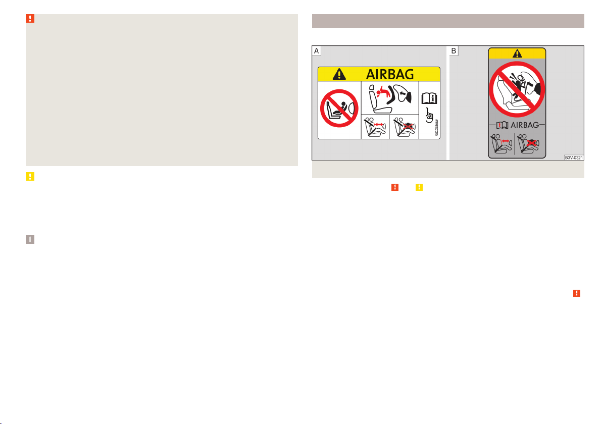
Use of a child seat on the front passenger seat
Does not apply to Taiwan
Fig. 10 Warning labels
Read and observe and on page 20 first.
Never use a rearward-facing child restraint system on a seat which is protected by an active airbag. This could cause serious injury to the child, even
death.
This warning is also given on stickers that are located in the following places.
▶
On the passenger sun visor » Fig. 10 - .
▶
On the B-column on the front passenger side » Fig. 10 – .
The following instructions must be followed when using a child seat on the
front passenger seat.
▶
It is essential to deactivate the front passenger airbag if using a child seat in
which the child is transported with its back facing the direction of travel »
▶
If possible, adjust the front passenger seat backrest so that it is as vertical,
so as to ensure secure contact between the passenger seat backrest and the
back of the child seat.
▶
If possible, move the front passenger seat backwards so that there is no contact between the front passenger seat and the child seat behind it.
▶
Set the height-adjustable front passenger seat as high up as possible.
▶
With child safety seats in groups 2 and 3, make sure that the loop-around fittings attached to the child seat headrest is positioned in front of or at the
same height as the loop-around fittings on the B pillar on the passenger side.
.
Transporting children safely
21
Page 24

WARNING
■
Never use a rear-facing child seat on the front passenger seat if the pas-
senger airbag is activated. This child safety seat is positioned in the deployment area of the front passenger airbag. The airbag may cause the child severe, or even fatal injuries, in the event of it being deployed.
■
Once a child seat in which the child is transported with its back to the direction of travel is no longer being used on the passenger seat, the front
passenger airbag should be reactivated.
Use of a child seat on the front seat
Applies to Taiwan
Fig. 11
Warning labels
Read and observe and on page 20 first.
No babies, infants or children to be carried on the passenger seat.
A label to this effect can also be found on the passenger's sun visor » Fig. 11.
Child safety and the side airbag
Fig. 12
Incorrect seated position of a
child who is not properly secured
– risk from the side airbag/Child
properly protected by safety seat
Read and observe and on page 20 first.
The child must not be positioned in the deployment area of the side airbag
» Fig. 12 - .
There must be sufficient room between the child and the deployment area of
the side airbag that the airbag can provide as much protection as possible
» Fig. 12 – .
Classification of child seats
Read and observe and on page 20 first.
Classification of child seats according to the ECE-R 44 standard.
Group Weight of the child
0 up to 10 kg
0+ up to 13 kg
1 9-18 kg
2 15-25 kg
3 22-36 kg
22
Safety
Page 25

Use of child safety seats which are secured with a safety belt
Never use a rear-facing child seat on the front passenger seat if the passenger airbag is activated. This child safety seat is positioned in the deployment area of
the front passenger airbag. The airbag may cause the child severe, or even fatal injuries, in the event of it being deployed.
Read and observe and on page 20 first.
Overview of the usability of child seats fastened with a seat belt on the different seat types, in accordance with the ECE-R 16 standard.
Group Front passenger seat Rear seats
0
up to 10 kg
0+
up to 13 kg
1
9-18 kg
2
15-25 kg
3
22-36 kg
The seat is suitable for the use of approved child seats in the “Universal”
U
weight group category.
U U
U U
U U
U U
U U
Fastening systems
Introduction
This chapter contains information on the following subjects:
Attachment points of the
Use of child safety seats with the
Attachment points of the
system
system 24
system 25
Attachment points of the system
Fig. 13
Attachment points of the
system
is a system for securing child seats quickly and safely.
There are two fixing eyes between the seat backrest and the seat cushion of
the rear passenger seat for fixing a child seat with the
WARNING
■
Always refer to the instructions of the manufacturer of the child seat
when installing and removing a child seat with the system.
■
Never attach other child seats, belts or objects to the attachment points
intended for the installation of a child seat with the
death!
23
Note
■
A child seat fitted with the system can only be mounted in a vehicle fit-
ted with a system if the child seat has been approved for this type of vehicle. Further information is available from a ŠKODA Partner.
■
Child seats with the
cessories.
system can be purchased from ŠKODA Original Ac-
system » Fig. 13.
system – risk of
Transporting children safely
23
Page 26

Use of child safety seats with the system
Never use a rear-facing child seat on the front passenger seat if the passenger airbag is activated. This child safety seat is positioned in the deployment area of
the front passenger airbag. The airbag may cause the child severe, or even fatal injuries, in the event of it being deployed.
Overview of the usability of child seats with the system on the various seat types, in accordance with the ECE-R 16 standard.
Group
0
up to 10 kg
0+
up to 13 kg
Size class of
the child seat
a)
Front passenger seat Rear seats
E X IL-SU
E
X IL-SUD
C
D
1
9-18 kg
C
B
X
B1
IL-SU
IUF
A
2
15-25 kg
3
22-36 kg
a)
The size category is shown on the label attached to the child seat.
- X IL-SU
- X IL-SU
IL-SU The seat is suitable for the use of approved child seats in in the “Semi-Universal”category. The “Semi-Universal” category means that the child seat
with the
system is approved for your vehicle. Observe the list of vehicles that comes with the child seat.
IUF The seat is suitable for the use of approved forward facing child seats in the “Universal” weight group category.
X The seat is not fitted with system attachment points.
24
Safety
Page 27

Attachment points of the system
Fig. 14
Attachment points of the
system
is a fastening system, which restricts the movement of the upper part
of the child seat.
The attachment points for attaching the belt for a child seat with the
system are located on the back of the rear seat backrests » Fig. 14.
WARNING
■
Always refer to the instructions from the manufacturer of the child seat
when installing and removing a child seat with the system.
■
Only use child seats with the
system on the seats with the at-
tachment points.
■
Only ever attach one belt from the child seat to a locking eye.
Transporting children safely
25
Page 28

Fig. 15 Cockpit example for LHD models
26
Using the system
Page 29

Using the system
cockpit
Overview
1
Electrical power windows 43
2
Door opening lever 40
3
Electric exterior mirror adjustment 50
4
Central locking system 39
5
Air outlet vents 66
6
Parking ticket holder 55
7
Operating lever (depending on equipment):
▶
Direction and high beam 46
▶
Speed regulating system
8
Steering wheel with horn / with driver's front airbag 16
9
Instrument cluster 28
10
Operating lever (depending on equipment):
▶
Windscreen wipers and washers 48
▶
Multifunction display
11
Buttons (depending on the specification):
▶
START-STOP 70
▶
Rear window heater
▶
Seat heater on the front left seat
12
Depending on equipment fitted:
▶
Controls for heating / air conditioning 65
13
Radio
14
Interior rear-view mirror 50
15
Buttons / warning lights (depending on the specification):
▶
Hazard lights 47
▶
airbag 19
▶
Seat heating for the front right seat 53
16
Fold-down hooks 59
17
Front passenger airbag 16
18
Storage compartment on the front passenger side 59
19
Power window in the front passenger door 43
20
Storage compartment 55
Warning light for the front seat passenger
21
Light switch 45
22
Bonnet release lever 96
23
Headlamp beam adjuster for the headlights 45
24
Steering wheel locking lever 12
25
Ignition lock 70
26
Cup holder 56
27
Buttons (depending on the specification):
▶
City Safe Drive
▶
Tyre pressure monitoring
28
Handbrake lever 72
29
Depending on equipment fitted:
▶
Gearshift lever (manual gearbox) 73
▶
Selector lever (automated gearbox)
30
80
Depending on specification:
▶
12-volt power outlet 58
▶
Cigarette lighter
31
Storage compartment 56
Note
The layout of the controls on right-hand drive vehicles differs partially from
30
that shown in this layout» Fig. 15.
48
53
81
83
74
57
cockpit
27
Page 30

Instruments and warning lights
Instrument cluster
Introduction
Fig. 16
Instrument cluster - Version 1
Fig. 17
Instrument cluster - Version 2
This chapter contains information on the following subjects:
Rev counter 28
Fuel gauge 29
Trip counter 29
Service interval display 30
Recommended gear 30
1
Speedometer
2
Display:
▶
With counter for distance driven » page 29
▶
With service interval display » page 30
▶
With multifunction display » page 30
▶
With outside temperature display
▶
With fuel gauge (only in the instrument cluster - variant 2) » Fig. 18 on
page 29 - .
3
Button:
▶
Switch between the counter for the distance driven (trip) and the odometer » page 29
▶
Reset counter for distance travelled (trip) » page 29
▶
Set the time » page 32
4
Fuel gauge » page 29
5
Engine revolutions counter » page 28
6
Time adjust button » page 32
The instruments are also illuminated when the side light or low beam light is
switched on.
Note
Appears in the display then the system indicates that the ignition is
switched on.
Rev counter
The tachometer 5 » Fig. 17 on page 28 shows the actual engine speed per minute.
The beginning of the red scale range of the tachometer indicates the maximum permitted engine speed of a driven-in and operating warm engine.
You should shift into the next highest gear before the red scale of the revolution counter is reached, or select mode D on the automatic gearbox.
The gear recommendation is important to note in order to maintain the optimum engine speed » page 30.
28
Using the system
Page 31

CAUTION
The rev counter pointer may only move into the red area for a short time - otherwise risk of engine damage!
Fuel gauge
Fig. 18 Petrol fuel gauge: Version 1/version 2
Fig. 19
Petrol and natural gas gauge
The fuel gauge only works if the ignition is switched on.
Vehicles with petrol engine
Fuel gauge types » Fig. 18
Display in the instrument cluster - Version 1
Display in the instrument cluster display - Version 2
The fuel tank has a capacity of about 35 litres.
When the fuel level goes down to the reserve level in the fuel tank, the warn-
ing light lights up in the display variant 1 or the symbol flashes in the display variant 2 for 10 seconds together with the remaining segments of the display. There are now about 4 litres of fuel remaining in the tank.
An audible signal sounds as a warning.
G-TEC vehicles (natural gas drive)
Fuel gauge » Fig. 19
1
Gasoline reserve
2
Natural gas reserve
The capacity of the gasoline fuel tank is approximately 10 litres. The capacity
of the natural gas fuel tank is approximately 11 kg.
When the vehicle runs on petrol, the pointer of the fuel gauge is in the range
1
. When the vehicle runs on petrol, the pointer of the fuel gauge is in the
range 2.
If the fuel level in the fuel tank reaches the reserve area for petrol, the warn-
ing light goes on. There are now about 5 litres of fuel remaining in the tank.
If the fuel level in the fuel tank reaches the reserve area for natural gas the
warning light goes on. There is now about 1.5 kg of fuel remaining in the
tank.
WARNING
In order for the vehicle systems to function properly and thus to make driving safe, there must be sufficient fuel in the tank. Never drive until the fuel
tank is completely empty - there is a risk of accidents!
CAUTION
Never drive until the fuel tank is completely empty! The irregular supply of fuel
can cause misfiring, which can result in serious damage to the engine and in
damage to the exhaust system.
Trip counter
Fig. 20
Counter for distance travelled
(trip)
Instruments and warning lights
29
Page 32

Display » Fig. 20
Counter showing the distance travelled since the last reset (trip)
Odometer
Choose between the odometer display and the counter showing the distance
driven (trip)
Press down on button 3 » Fig. 16 on page 28 or » Fig. 17 on page 28 briefly.
›
Reset counter for distance travelled (trip)
Select the counter for the distance driven (trip) and press down on button
›
» Fig. 16 on page 28 or » Fig. 17 on page 28.
Service interval display
The service interval display shows the mileage to the next service event.
Before the next service interval has been reached, the message
the instrument cluster display for some seconds and the remaining kilometres
are shown after switching on the ignition.
If the time of the service has been reached, an acoustic signal will sound and
the message
Information regarding the service intervals » page 87.
appears for a few seconds after switching on the ignition.
appears in
Recommended gear
Fig. 21
Information on the selected
gear / Recommended gear
Display » Fig. 21
Optimal gear engaged
Recommended gear (e.g. means that it would be beneficial to change
from 3rd gear to a higher gear)
For vehicles with automatic transmission the recommended gear will be
shown when the mode for manual gear-changing (Tiptronic) is selected.
3
WARNING
The driver is always responsible for selecting the correct gear in different
driving situations (e.g. when overtaking).
Driving data (multifunction display)
Introduction
This chapter contains information on the following subjects:
Operation
Information overview 31
Warning at excessive speeds 31
Memory 31
32
The driving data display only works when the ignition is switched on.
Operation
Fig. 22
Buttons on the control lever
30
A suitable engaged gear or, where appropriate, a recommended gear is displayed, with the aim of conserving the life of the engine and increasing driving
efficiency.
30
Using the system
Page 33

Operating the multifunction display » Fig. 22
A
Press (up or down) - Select data / Setting values
B
Press Show / confirm entry
Hold - Reset memory
WARNING
Even at temperatures of around +4 °C, black ice may still be on the road
surface! You should therefore not only rely on the outside temperature display for accurate information as to whether there is ice on the road.
Information overview
Overview of driving data (depending on the vehicle equipment).
Clock - current time is displayed.
Outside temperature - If the outside temperature drops below +4 °C, the tem-
perature indicator appears and a snowflake symbol (display for low temperature) flashes for a few seconds, then remains displayed together with the
outside temperature.
Driving time - Driving time since last clearing the memory.
Current fuel consumption - When the vehicle is stationary or moving slowly,
the fuel consumption is displayed in l/h (in models in some countries the following appears --,- km/l).
Average fuel consumption - Is calculated continuously since the last clearing
of the memory. After erasing the memory, no data will appear for the first 300
m driven.
Range - Drive distance in km which can be covered with the existing tank capacity and with the same driving style. If you drive more efficiently this value
can increase.
Distance driven - Distance driven since the memory was last cleared.
Average speed - Value constantly recalculated, for distance since last clearing
the memory. After erasing the memory, no data will appear for the first 300 m
driven.
Current Speed - Digital speedometer.
Coolant temperature - If the coolant temperature is in the range 70-120 °C,
the engine operating temperature has been reached. If the temperature is below 70 ° C, high engine speeds and straining the engine should be avoided. If
the temperature is over 120 ° C, the warning light lights up the instrument
cluster » page 34.
Warning of excessive speed - It is possible to set a speed limit.
Warning at excessive speeds
The system offers the possibility of setting a speed limit which, if exceeded,
sounds an acoustic warning signal and at the same time displays the menu
item (warning of excessive speed) with the limit set.
Adjust the speed limit while the vehicle is stationary
Select and confirm the menu item (warning when speed limit is exceeded).
›
Set the desired speed limit.
›
Confirm the set value, or wait several seconds; your settings will be saved
›
automatically.
Adjusting the speed limit while the vehicle is moving
Select and confirm the menu item (warning when speed limit is exceeded).
›
Drive at the desired speed.
›
Confirm the current speed as the speed limit.
›
The set speed limit can be manually adjusted later if needed.
Reset speed limit
Select and confirm the menu item (warning when speed limit is exceeded).
›
By confirming the speed stored in the memory, the speed limit is reset.
›
The set driving mode remains stored even after switching the ignition on and
off. If the break in a journey exceeds 2 hours, the pre-set speed limit is deactivated.
Memory
Fig. 23
Multi-function display - Display
example of the memory
Instruments and warning lights
31
Page 34

The system stores data from the two memories described below, which are
then displayed at position A» Fig. 23.
“1” - Single-trip memory
Drive data is stored from when the ignition is switched on to when it is switched off. If the trip is continued within 2 hours after switching off the ignition,
new data will also flow into the calculation of the current driving information.
If the trip is interrupted for more than 2 hours, the memory is automatically
erased.
“2” - Long-term memory
The memory gathers driving information from any number of individual journeys up to a total of 19 hours and 59 minutes driving or 1,999 kilometres driven.
The indicator is automatically set back to zero if one of these two values is exceeded.
To select the preferred memory bank choose the desired specification of the
›
multi-function display and select by repeatedly confirming the preferred
memory bank.
To reset the memory bank see » page 30, Operation.
The following drive data is stored in different memory banks.
▶
Average fuel consumption.
▶
Distance driven.
▶
Average speed.
▶
Driving time.
Note
Disconnecting the vehicle battery will delete all memory data.
Fig. 24
Buttons in the instrument cluster - variant 1
Switch on the ignition.
›
Press down button A until» Fig. 24the hour flashes in the display.
›
The hour is set by repeatedly pressing button B.
›
Switch to the minutes by pressing button A.
›
The minutes are set by repeatedly pressing button B.
›
Confirm the value entered by pressing button A again, or wait for around 5
›
seconds. The setting is saved automatically (the value stops flashing).
Warning lights
Introduction
This chapter contains information on the following subjects:
Hand brake
Braking system 33
Front seat belt warning light 33
Alternator 33
Engine oil pressure 33
Coolant 34
Automatic transmission 34
Power steering 34
Stability control (ESC) / Traction control (TCS) 35
Anti-lock braking system (ABS) 35
Tyre pressure 35
Rear fog light 36
Emission control system 36
Engine electronics check 36
Airbag system 36
Handbrake - automatic transmission 36
Brake pedal (automatic transmission) 36
Turn signal system 37
Cruise control system 37
Main beam 37
/ Rear seat belt warning light 37
City Safe Drive 37
/ START-STOP 37
The warning lights in the instrument cluster indicate the status of certain
functions or the presence of faults.
33
32
Using the system
Page 35

The lighting up of some warning lights may be accompanied by acoustic signals.
After switching on the ignition, some warning lights light up briefly as a function test. If the tested systems are OK, the corresponding warning lights extin-
guishes for a few seconds after switching on the ignition or after starting the
engine.
WARNING
■
Ignoring light-up indicator lamps in the instrument cluster and the control
symbols in the display may cause serious injury or damage to the vehicle.
■
If you have to stop for technical reasons, then park the vehicle at a safe
distance from the traffic, switch off the engine and activate the hazard
warning light system » page 47. Place the warning triangle at the prescribed distance.
■
The engine compartment of your car is a hazardous area. The following
warning instructions must be followed at all times when working in the engine compartment » page 96, Engine compartment.
Hand brake
Read and observe
lights up – the hand brake has been applied.
An audible warning is also given if you drive the vehicle for at least 3 seconds
at a speed of more than 6 km/h.
Braking system
Read and observe on page 33 first.
lights up - the brake fluid level in the brake system is too low or there is an
ABS fault.
▶
Stop the vehicle, switch off the engine, and check the level of the brake fluid
» page 101.
on page 33 first.
WARNING
■
If the warning light lights up at the same time as warning light
» page 35, Anti-lock braking system (ABS), do not continue your
journey! Seek help from a specialist garage.
■
A fault to the ABS system or the braking system can increase the vehi-
cle's braking distance – risk of accident!
Front seat belt warning light
Read and observe
lights up - the driver or front passenger has not fastened their seat belt.
At a speed of over 20 km/h the warning light flashes and an audible warning
sounds at the same time.
The warning signal is switched of and the indicator light is permanently lit if
the driver and front passenger have not fastened their seat belts within the
next 90 seconds.
Alternator
Read and observe
lights up – the battery is not being charged whilst the engine is running.
▶
Seek help from a specialist garage.
CAUTION
If, while driving, the warning light lights up in addition to the warning
light » page 34, do not drive any further - risk of damage to the engine!
Switch off the engine and seek assistance from a specialist garage.
Engine oil pressure
Read and observe
lights up or flashes - the engine oil pressure is too low.
An audible signal sounds as a warning.
on page 33 first.
on page 33 first.
on page 33 first.
Instruments and warning lights
33
Page 36

▶
Stop the vehicle, switch off the engine, and check the engine oil level
» page 99, Check and refill.
▶
If the warning light lights up or flashes, do not drive any further, even if
the oil level is correct! Switch off the engine and seek assistance from a specialist garage.
CAUTION
■
The oil pressure light is not an oil level indicator! One should therefore
check the oil level at regular intervals, preferably after every refuelling stop.
■
If for some reason it is not possible to top up the engine oil under the current
circumstances, do not continue driving! Switch off the engine and seek assistance from a specialist garage.
Coolant
Read and observe
lights up or flashes – the coolant temperature is too high or the coolant lev-
on page 33 first.
el is too low.
An audible signal sounds as a warning tone.
▶
Stop the vehicle, switch off the engine, and allow the engine to cool down.
▶
Check the coolant level, if necessary top up the coolant.
If the coolant level is within the specified range and the warning light lights
up or flashes again, then there may be a malfunction of the cooling fan.
▶
Switch off the ignition.
▶
Check the fuse for the cooling fan, replace if necessary.
If the coolant level and fan fuse are both OK but the warning light is still
illuminated, do not drive any further!
▶
Seek help from a specialist garage.
Automatic transmission
Read and observe
fault
lights up - there is a fault in the automatic transmission.
An audible signal sounds as a warning tone.
▶
Do not drive the vehicle! Switch off the engine and seek assistance from a
specialist garage.
on page 33 first.
Functional impairment
lights up and gear change is not possible - for technical reasons there may
be an impairment of the automatic transmission.
▶
Stop the car, turn the ignition off and on again.
If the warning light lights up after you again switch on the ignition, seek assistance from a specialist garage.
Gearbox overheating
and is possibly also illuminated - the automatic transmission is overheat-
ing.
An audible signal sounds as a warning tone.
▶
Stop and allow the transmission to cool down or drive more quickly than
20 km/h (12 mph).
If the warning light lights up again, switch off the vehicle, shut off the engine and allow the gearbox to cool down.
Further information » page 74, Automated transmission.
Power steering
Read and observe on page 33 first.
Fault in the power steering
lights up – this indicates a complete failure of the power steering and the
steering assist is no longer working (significantly higher steering forces).
lights up – this indicates a partial failure of the power steering and the
steering forces can be greater.
▶
Switch off the ignition, start the engine again and travel a short distance.
▶
If the warning light does not go out, obtain assistance from an authorised
dealer.
Disconnecting the vehicle battery
If the vehicle's battery has been disconnected and reconnected, the warning
light comes on after switching on the ignition.
The warning light should go out after driving a short distance.
If, after the motor is restarted and a short drive, the indicator light does not go
out, there is a system error.
▶
Seek help from a specialist garage.
34
Using the system
Page 37

Stability control (ESC) / Traction control (TCS)
Read and observe on page 33 first.
flashes – the ESC or TCS is currently active.
lights up – there is an ESC or TCS fault.
▶
Seek help from a specialist garage.
As the ESC operates in conjunction with the ABS, the ESC warning light will also come on if the ABS system fails.
If the warning light comes on after starting the engine, the ESC or TCS may
have been switched off for technical reasons.
▶
Switch the ignition off and on again.
If the warning light does not illuminate after you switch the engine back on,
the ASR is fully functional again.
Disconnecting the vehicle battery
If the vehicle's battery has been disconnected and reconnected, the warning
light comes on after switching on the ignition.
The warning light should go out after driving a short distance.
If, after a short drive, the indicator light does not go out, there is a system er-
ror.
▶
Seek help from a specialist garage.
More information about the ESC system » page 78, Stability Control (ESC) or
TCS system » page 78, Traction control (TCS).
Anti-lock braking system (ABS)
Read and observe
lights up – there is an ABS fault.
The vehicle will only be braked by the normal brake system without the ABS.
▶
Seek help from a specialist garage.
In the event of an ABS fault, the other braking and stabilization systems are
turned off » page 77, Braking and stabilisation systems .
on page 33 first.
WARNING
■
If the ABS warning light together with the indicator light » page 33,
Braking system lights up, do not continue to drive! Seek help from a
specialist garage.
■
A fault to the ABS system or the braking system can increase the vehi-
cle's braking distance – risk of accident!
Tyre pressure
Read and observe
on page 33 first.
Change of tyre pressure values
lights up– there was a pressure change in one of the tyres.
An audible signal sounds as a warning.
▶
Immediately reduce speed and avoid sudden steering and braking manoeuvres.
▶
Stop the vehicle, turn the ignition off and check the tyres and their inflation
pressures » page 104.
▶
Correct the tyre pressure if necessary or replace the affected wheel
» page 108 or use the repair kit » page 111.
▶
Save the tyre pressure values in the system » page 83.
System fault
flashes for approximately 1 minute and remains lit – there may be a fault in
the tyre pressure monitoring system.
▶
Stop the vehicle, turn the ignition off and start the engine again.
If the warning light flashes again after the engine has started, there is a
system error.
▶
Seek help from a specialist garage.
Disconnecting the vehicle battery
If the vehicle's battery has been disconnected and reconnected, the warning
light comes on after switching on the ignition.
The warning light should go out after driving a short distance.
If, after a short drive, the indicator light does not go out, there is a system er-
ror.
▶
Seek help from a specialist garage.
Instruments and warning lights
35
Page 38

Other incidents
The following reasons can explain the warning light being illuminated.
▶
The vehicle is loaded on one side. Distribute the load evenly.
▶
The wheels of one axle are loaded more heavily (e.g. when driving uphill or
downhill).
▶
Snow chains are mounted.
▶
A wheel has been changed.
CAUTION
Under certain circumstances (e.g. sporty style of driving, wintry or unpaved
roads) the warning light in the instrument cluster can be delayed or does
not light up at all.
Rear fog light
Read and observe
lights up – the rear fog light is switched on.
Emission control system
Read and observe
lights up – there is a fault in the emission control system. The system
makes it possible to drive on in emergency mode - there may be a noticeable
reduction in engine performance.
▶
Seek help from a specialist garage.
Engine electronics check
Read and observe on page 33 first.
lights up – there is a fault in the engine management system. The system
makes it possible to drive on in emergency mode - there may be a noticeable
reduction in engine performance.
▶
Seek help from a specialist garage.
on page 33 first.
on page 33 first.
Airbag system
Read and observe on page 33 first.
System fault
lights up - there is a fault in the airbag system.
This also applies if the warning light does not come on when the ignition is
switched on.
The functionality of the airbag system is monitored automatically even if one
of the airbags is switched off.
One of the airbags or a belt tensioner has been disabled by the diagnostic
tool
lights up for approximately 4 seconds after the ignition is switched on and
then flashes for approximately 12 seconds.
The front passenger airbag has been disabled with the key switch
lights up for a few seconds when the ignition is switched on.
below the lettering
up after switching on the ignition» page 19, Deactivating the front passenger
airbag.
WARNING
When a fault in the airbag system occurs, there is a risk of the system not
being triggered in the event of an accident. Therefore, this must be
checked immediately by a specialized garage.
Handbrake - automatic transmission
Read and observe on page 33 first.
lights up or flashes - engage the parking brake.
Further information » page 74, Automated transmission.
Brake pedal (automatic transmission)
Read and observe on page 33 first.
lights up – apply the brake.
Further information » page 74, Automated transmission.
in the middle of the dash panel lights
36
Using the system
Page 39

Turn signal system
Read and observe on page 33 first.
flashes – the left turn signal is turned on.
flashes – the right turn signal is turned on.
If there is a fault in the turn signal system, the warning light flashes at twice
its normal rate.
When the hazard warning light system is switched on, this will cause all of the
turn signal lights as well as both warning lights to flash.
Cruise control system
Read and observe on page 33 first.
lights up – the vehicle speed is regulated by the cruise control system.
Main beam
Read and observe on page 33 first.
lights up – the main beam or the headlight flasher is switched on.
/ Rear seat belt warning light
Read and observe on page 33 first.
lights up – a rear seat belt is not fastened.
lights up – a rear seat belt is fastened.
When the seat belt is fastened/unfastened, the particular light lights up briefly
and indicates the current belt status!
If the system is turned off and the vehicle is moving at a speed of about 5-30
km/h, the warning light lights up in the instrument cluster display.
If the system is activated again, the warning light
ment cluster display for about 5 s.
Further information » page 81, City Safe Drive.
/ START-STOP
Read and observe on page 33 first.
lights up - the START-STOPsystem is active.
lights up - the START-STOPsystem is active, but the automatic engine cut-
off is not possible.
flashes - the START-STOPsystem is not available.
Further information » page 70, START-STOPsystem.
lights up in the instru-
City Safe Drive
Read and observe on page 33 first.
flashes quickly - the City Safe Drivesystem is braking the vehicle automati-
cally.
flashes slowly - the system is not available or there is a system malfunction.
Instruments and warning lights
37
Page 40

Unlocking and opening
Unlocking and locking
Introduction
This chapter contains information on the following subjects:
Unlock / lock using key and lock 38
Unlocking/locking with the remote control key 39
Vehicle unlocking / locking with the door opening lever 39
Vehicle locking / unlocking with the central locking button 39
SafeLock 40
Opening/closing a door 40
Child safety lock 41
Malfunctions 41
The vehicle may be equipped with a central locking system which makes it
possible to unlock/lock all doors and the boot lid simultaneously.
The turn signal lights flash twice as confirmation that the vehicle has been un-
locked.
If you unlock the vehicle and do not open a door or the boot lid within the next
30 seconds, the vehicle will lock again automatically.
The turn signal lights flash once as confirmation that the vehicle has been
locked.
If the driver's door has been opened, the vehicle cannot be locked.
If the doors or the luggage compartment lid remain open after the vehicle has
been locked, the turn signal lights do not flash until they have been closed.
Automatic locking / unlocking of a vehicle with central locking system
This function enables the locking of all doors and the boot lid from a speed of
15 km / h. Opening the doors and the boot lid from the outside is not possible.
Renewed automatic unlocking of all doors as well as the luggage compartment
door when removing the ignition key or by opening any of the doors.
WARNING
■
Never leave the key in the vehicle when you exit the vehicle. Unauthorised persons (e.g. children) could lock the car, turn on the ignition or start
the engine - danger of injury and accidents!
■
When leaving the vehicle, never leave persons who are not completely independent, such as children, unattended in the vehicle. These individuals
might not be able to exit the vehicle by themselves or to help themselves.
Can be fatal at very high or very low temperatures!
CAUTION
■
Each key contains electronic components; therefore it must be protected
against moisture and severe shocks.
■
Keep the key grooves clean. Impurities (textile fibres, dust etc.) have a nega-
tive effect on the functionality of the locking cylinder and ignition lock.
Unlock / lock using key and lock
Fig. 25
Left side of the vehicle: Turning
the key for unlocking and locking
the vehicle
Read and observe and on page 38 first.
Unlocking/locking the vehicle with the key » Fig. 25
Unlocking the vehicle
Locking the vehicle
38
Using the system
Page 41

Unlocking/locking with the remote control key
Fig. 26
Key with pop-out key bit
Read and observe and on page 38 first.
Description of the key » Fig. 26
Unlock button
Lock button
Button to unlock the boot lid
A
Button for popping out/pushing in the key bit
B
Battery status warning light - if the warning light does not flash when you
press a button on the key, the battery is discharged.
Unlocking / locking the boot lid
By pressing lightly on the button the lid is unlocked.
By pressing down on the button the lid is unlocked and unlatched (part-
opened).
If the lid is unlocked or released with the button , then the lid is automati-
cally locked after closing. The period of time after which the flap is locked can
be set » page 42.
CAUTION
■
The remote control may be affected by signal superimposition by transmit-
ters close to the car.
■
The range of the remote control key is about 30 m. The battery must be replaced if the central locking only reacts to the remote control at a distance of
less than 3 m away » page 116.
Vehicle unlocking / locking with the door opening lever
Fig. 27 Door opening lever
Read and observe and on page 38 first.
On vehicles without central locking, you can lock and unlock doors which do
not have a locking cylinder from the inside.
To unlock the door, push the door opening lever in the direction of the arrow
›
so that the red marking A is visible » Fig. 27.
To unlock the door pull the door opening lever.
›
Vehicle locking / unlocking with the central locking button
Fig. 28
Central locking button
Read and observe and on page 38 first.
Prerequisites for locking / unlocking with the central locking button
The vehicle is not locked from the outside.
None of the doors are open.
To lock, press the button » Fig. 28.
›
To unlock, press the button .
›
Unlocking and opening
39
Page 42

The following applies after locking.
▶
Opening the doors and the boot lid from the outside is not possible.
▶
The doors can be unlocked and opened from the inside by a single pull on the
opening lever of the respective door.
WARNING
Doors locked from the inside make it difficult for rescuers to get into the
vehicle in an emergency – risk to life!
SafeLock
Read and observe and on page 38 first.
SafeLock prevents the door from being opened from the inside. This makes an
attempted break-in to the vehicle more difficult.
Activating
SafeLock is activated when the vehicle is locked from the outside.
This function is pointed out by the following message
the instrument cluster after switching out the ignition.
Activation display
When SafeLock is activated the warning light in the driver's door flashes for 2
seconds in rapid succession, then starts to flash at longer intervals.
Deactivating
The safelock can be switched off by locking twice within 2 seconds.
The warning light in the driver door flashes rapidly for about 2 seconds, then
goes out and starts to flash at longer intervals after about 30 seconds.
If the vehicle is locked and the safe securing system is switched off, the door
can be opened separately from the inside by a single pull on opening lever.
The Safelock system switches back on when the vehicle is locked.
WARNING
If the car is locked and the safe securing system activated, no people must
remain in the car as it will then not be possible to either unlock a door or
open a window from the inside. The locked doors make it more difficult for
rescuers to get into the vehicle in an emergency – risk to life!
on the display of
Opening/closing a door
Fig. 29 Door handle/door opening lever
Read and observe
To open from the outside, unlock the vehicle and pull in the direction of ar-
›
row » Fig. 29 the door handle A.
To open from the inside pull the door opening lever B and push the door
›
away from you.
To the lock from the inside grab handle C and close the door.
›
WARNING
■
The door must be closed properly, otherwise it could open whilst the ve-
hicle is in motion - risk of fatality!
■
Only open and close the door when there is no one in the opening/closing
range – risk of injury!
■
Never drive with the doors open - there is a risk of death!
■
An opened door can close automatically if there is a strong wind or the
vehicle is on an incline – risk of injury!
and on page 38 first.
40
Using the system
Page 43

Child safety lock
Fig. 30 Rear door: Child safety lock switch on / off
Read and observe
The child safety lock prevents the rear door from being opened from the inside. The door can only be opened from the outside.
To turn on the child safety lock, turn the vehicle key to position » Fig. 30.
›
To turn off the child safety lock, turn the vehicle key to position .
›
and on page 38 first.
Malfunctions
Read and observe and on page 38 first.
Synchronise remote
If the buttons on the remote control key have been depressed several times
beyond the effective range of the equipment or the battery has been replaced
in the remote control key and the vehicle cannot be unlocked with the remote
control, the key must be synchronised.
Press any button on the remote control key.
›
Unlock the door with the key in the lock cylinder within 1 minute of pressing
›
the button.
Central locking fault
If the warning light in the driver's door initially flashes quickly for around 2 seconds, and then lights up for 30 seconds without interruption before flashing
again slowly, you will need to seek the assistance of a specialist garage.
A failure in the central locking system can lead the vehicle doors and the boot
lid can emergency lock or emergency release » page 116.
Low voltage of the key battery
Replace the battery » page 116.
Luggage compartment lid
Introduction
This chapter contains information on the following subjects:
Opening / closing the boot lid 42
Delayed locking of the boot lid 42
Button A » Fig. 31 on page 42 is disabled when starting off or driving at a
speed of over 9 km/h. The button is reactivated when the vehicle has stopped
and a door is opened.
WARNING
■
Never drive with the luggage compartment lid open or ajar, as otherwise
exhaust gases may get into the interior of the vehicle – risk of poisoning!
■
Ensure that the lock is properly engaged after closing the lid. Otherwise,
the lid might open suddenly while the vehicle is moving, even if the lid was
locked – risk of accident!
■
Make sure that when closing the boot lid, no body parts are crushed there is danger of injury!
■
Do not press on the rear window when closing the luggage compartment
lid, it could crack – risk of injury!
Unlocking and opening
41
Page 44

Opening / closing the boot lid
Fig. 31 Opening / closing the boot lid
Read and observe
To open the lid, press » Fig. 31buttonA in the direction of arrow 1.
›
Raise the lid in the direction of the arrow 2 .
›
To close it, grip recess B and pull in the direction of arrow 3.
›
on page 41 first.
The windows can be operated mechanically by means of the handle attached
to the respective door panel.
The windows can be operated electrically from the following locations; the
front windows from the driver's seat and also via the buttons for the windows
in the passenger door.
WARNING
Always close the window carefully and in a controlled manner. Otherwise
these could cause severe crushing injuries!
CAUTION
■
Keep the windows clean (free of ice and similar) to ensure the correct func-
tionality of the electric windows.
■
Always close the electric windows before disconnecting the battery.
Note
If the windows are open, dust as well as other dirt can get into the vehicle and
in addition the wind noise is more at certain speeds.
Delayed locking of the boot lid
Read and observe on page 41 first.
If the boot lid is unlocked with the button on the key, then the boot lid is
automatically locked after closing.
The period after which the boot lid is locked automatically can be extended by
a specialist garage.
CAUTION
There is a risk of unwanted entry into the vehicle before the boot lid is locked
automatically.
Window operation
Introduction
This chapter contains information on the following subjects:
Mechanical window openers 42
Electric windows 43
Manually opening/closing rear windows 43
42
Using the system
Mechanical window openers
Fig. 32 Window operation: left / right
Read and observe and on page 42 first.
To open, turn the crank in the direction of arrow A » Fig. 32.
›
To close, turn the crank in the direction of arrow B.
›
Page 45

Electric windows
Manually opening/closing rear windows
Fig. 33 Buttons for window levers
Read and observe
The electrical power windows can only be operated when the ignition is
switched on.
The windows in the front doors can be operated from the driving position. The
front passenger window is operated using the button in the passenger door.
Power window buttons » Fig. 33
A
Front door left
B
Front door right
To open, press down the appropriate button until the window has moved in-
›
to the desired position.
To close it, pull gently on the top edge of the button until the window has
›
moved into the desired position.
and on page 42 first.
Fig. 34 Opening/closing rear windows
Read and observe
To open, grasp the safety catch in recess A» Fig. 34.
›
Open the window in the direction of arrow 1 and lock it by pressing down
›
the safety catch in the direction of arrow 2 to the stop.
To close, grasp the safety catch in recess A.
›
Pull the safety catch in the opposite direction to arrow 2 and pull the win-
›
dow back to its starting position in the opposite direction to 1 until the
safety catch clicks into place.
and on page 42 first.
Panoramic tilt / slide sunroof
Introduction
This chapter contains information on the following subjects:
Operation 44
Force limiter 44
Activate operation of the tilt / slide sunroof 44
Manually operated sunblind 44
The panoramic tilt / slide sunroof (hereinafter referred to as tilt / slide sunroof)
can only be operated when the ignition is turned on and when the outdoor
temperature is above -20 °C.
WARNING
When operating the tilt/slide sunroof and the sunshade, proceed with caution to avoid causing crushing injuries – risk of injury!
Unlocking and opening
43
Page 46

CAUTION
■
During the winter it may be necessary to remove any ice and snow in the vicinity of the sliding/tilting roof before opening it to prevent any damage to the
opening mechanism.
■
Always close the sliding/tilting roof before disconnecting the battery.
Operation
Fig. 35 Operation of the sliding/tilting roof
Read and observe and on page 43 first.
The sun roof can be operated with the rotary switch.
Operation of the tilt / slide sunroof » Fig. 35
Open fully
Open to the low-noise position
A
Open partially
Close completely
1
Opening (switch in position )
2
Closing (switch in position )
After turning the switch one stop to position (spring-tensioned position),
the tilt / slide sunroof stops in the position in which the intensity of the wind
noise is low. After turning the switch further to position , the tilt / slide sunroof opens up to the stop.
Force limiter
Read and observe
The sliding/tilting roof is fitted with a force limiter.
and on page 43 first.
If there is an obstacle, the closing process is stopped and the glass pane retracts by several centimetres.
WARNING
If the tilt / slide sunroof is closed, by pulling on the recess of the switch in
the direction of arrow 2, » Fig. 35 on page 44 and the closing process is
hindered by an obstacle, then at the third attempt at closing, the force limitation will cease to function (if less than 5 s passes between the individual
attempts to close). The tilt / slide sunroof closes with full force - this can
cause injury.
Activate operation of the tilt / slide sunroof
Read and observe and on page 43 first.
If the tilt / slide sunroof stops working (e.g. after disconnecting and connecting
the battery), then the operation must be reactivated.
Turn on the ignition and set the switch to position » Fig. 35 on page 44.
›
Press the switch on the recess E down and pull forwards.
›
The tilt / slide sunroof opens and closes again after around 10 seconds.
Release the lever.
›
Manually operated sunblind
Fig. 36
Operation of the sunblind
Read and observe and on page 43 first.
To open, pull the handle in the direction of arrow A » Fig. 36.
›
To close, pull the handle in the direction of arrow B.
›
44
Using the system
Page 47

Lights and visibility
Lights
Introduction
This chapter contains information on the following subjects:
Operation of the light function 45
Daylight running lights (DAY LIGHT) 45
Turn signal and main beam 46
Fog lights/rear fog light 46
Hazard warning light system 47
Parking light 47
Driving abroad 47
Unless otherwise stated, the lights only work when the ignition is on.
The layout of the controls on right-hand drive vehicles differs partially from
that shown in this layout» Fig. 37 on page 45.
Note
The headlights may mist up temporarily. When the light is on, the light-emitting surface demists after a short time.
Operation of the light function
Fig. 37
Light switch and control dial for
the headlight range control
To switch the light function on / off, switch A » Fig. 37 should be turned to
one of the following positions.
Switching off lights (except daytime running lights)
Switch on daytime running lights and side lights or parking lights
» page 47
Turn on the low beam
To adjust the headlight range control, turn dial B » Fig. 37 in line with the vehicle load » .
Front seats occupied, boot empty
All seats occupied, boot empty
All seats occupied, boot loaded
Driver seat occupied, boot loaded
WARNING
Always adjust the headlight beam to meet the following conditions - otherwise risk of accident.
■
The vehicle does not dazzle other road users, especially oncoming vehi-
cles.
■
The beam range is sufficient for safe driving.
CAUTION
If leaving the vehicle without needing the parking lights on, always turn the
light switch to position .
Note
■
If the light switch is in the position , the ignition key is removed and the
driver's door is open, an audible warning signal will sound. After a few seconds
or after closing the driver's door, the audible alarm switches off, but the parking lights will remain switched on.
■
The light switch is in position , the lighting of the instrument cluster is
switched off.
Daylight running lights (DAY LIGHT)
The daytime running lights light up the area in front of and to the rear of the
vehicle (only applicable for some countries).
Lights and visibility
45
Page 48

The daytime running lights are switched on automatically if the following
conditions are met.
The ignition is switched on.
The light switch is in the position or .
The light switch is in position and the fog lights are turned on, the daytime
running lights will turn off.
WARNING
Always switch on the low beam when visibility is poor.
WARNING
Only turn on the main beam or the headlight flasher if other road users will
not be dazzled.
Note
An acoustic warning signal will sound when the driver's door is opened if the
lever is not in the middle position after removing the ignition key from the ignition lock. The acoustic warning signal will stop just as soon as the driver's door
is closed.
Turn signal and main beam
Fig. 38
Operating lever: Turn signal and
main beam operation
Operating lever positions » Fig. 38
Switch on right turn signal
Switch on left turn signal
Switch on main beam (spring-tensioned position)
Switching off main beam / switching on headlamp flasher (spring-loaded
position)
The main beam can only be switched on when the low beam lights are on.
The headlight flasher can be operated even if the ignition is switched off.
The turn signal switches off automatically, depending on the steering angle
after completing the turn.
Comfort signalling
When the operating lever is pressed lightly up or down, the indicator in question flashes three times.
46
Using the system
Fog lights/rear fog light
Fig. 39
Light switch - switch on front
and rear fog light
Switching on the fog lights / rear fog lights is possible if the following conditions apply.
The light switch is in the position or » Fig. 39.
To turn on the fog lights pull the light switch to position 1, the indicator
›
light will light up in the light switch.
To turn on the rear fog light, pull the light switch to position 2, the indica-
›
tor light will light up in the instrument cluster.
If the vehicle is not fitted with fog lights, the rear fog light is switched on by
pulling out the light switch to the only possible setting.
The fog lights/rear fog light are switched off in the reverse order.
Page 49

Hazard warning light system
Fig. 40
Button for hazard warning light
system
To switch on/off, press the button» Fig. 40.
›
When first switched on, the turn signal lights and the warning light buttons
all flash at the same time as the warning lights in the instrument cluster.
The hazard warning light system can also be operated if the ignition is switched off.
If one of the airbags is deployed, the hazard warning light system will switch
on automatically.
Parking light
The side light is provided for lighting of the parked vehicle.
Switching on the parking light on one side
Switch off the ignition.
›
Press the control lever all the way into position or until it stops» Fig. 38
›
on page 46.
The parking light is turned on on the relevant side of the vehicle.
Switching on the side light on both sides
Turn the light switch » Fig. 39 on page 46 to position and lock the vehicle,
›
the parking light is turned on.
After pulling out the ignition key and opening the driver's door, an audible
warning sounds. After a few seconds or after closing the driver's door, the audible warning is turned off.
CAUTION
Turning on the parking light means the battery is heavily loaded.
Driving abroad
When driving in countries with opposing traffic system (traffic on the
left/right), your headlights may dazzle oncoming traffic. Therefore, it is necessary to have the headlights adapted by a specialist garage.
Interior lighting
Introduction
This chapter contains information on the following subjects:
Interior light
With the ignition off, the lights turn off automatically after about 10 minutes.
Interior light
Fig. 41
Interior lighting: Version 1/version 2
Positions for light switch A » Fig. 41
Switching on
Automatic operation (centre position)
Switching off
Switch on / off (by pressing the relevant switch B) » Fig. 41
Reading lamp left
Reading lamp right
47
Lights and visibility
47
Page 50

Automatic operation - position
The system is turned on when any of the following is present.
▶
The vehicle is unlocked.
▶
One of the doors is opened.
▶
The ignition key is removed.
The system is turned off when any of the following is present.
▶
The vehicle is locked.
▶
The ignition is switched on.
▶
About 30 seconds after all the doors have been closed.
Visibility
Introduction
This chapter contains information on the following subjects:
Rear window heater
Front sun visors 48
WARNING
No objects should be attached to the sun visor that could restrict the view
or endanger the vehicle occupants during sudden braking or in a collision.
48
Rear window heater
Fig. 42
Button for rear window heater
When the heater is switched on, a lamp illuminates inside the button.
The heating switches off automatically after approximately 10 minutes.
Note
If the on-board voltage decreases, the heating switches off automatically
» page 101, Automatic shutdown of consumers - vehicle battery discharge
protection.
Front sun visors
Fig. 43 Sun visor: Driver's side/front passenger's side
Read and observe on page 48 first.
Operation and description of the sun visor » Fig. 43
1
Swivel cover towards the windscreen
2
Swivel cover towards the door
A
Parking ticket band (if part of the specification)
B
Make-up Mirror (depending on equipment, this can be in both the driver’s
and passenger’s sun visors)
Windscreen wipers and washers
Read and observe on page 48 first.
The heater allows rapid defrosting and ventilation of the rear window.
The heating only works when the engine is running.
To switch the heating on / off, press button » Fig. 42.
›
48
Using the system
Introduction
This chapter contains information on the following subjects:
Front wipers and washers
Rear wiper and washer 49
The windscreen wipers and the windscreen washer system only operate if the
ignition is switched on.
49
Page 51

WARNING
Do not use the windscreen washer system at low temperatures, without
heating the windscreen beforehand. The window washer fluid could otherwise freeze on the windscreen and restrict the view to the front.
High-speed wiping
Single wipe of the windscreen (spring-loaded position)
Spraying and wiping the disc (spring-loaded position) - after releasing the
operating lever the wipers continue for another 1 to 3 strokes
CAUTION
■
If the windscreen wipers are in the switched-off position, they cannot be
raised off the windscreen. The wipers must be set to the service position to
raise them off the windscreen » page 117.
■
In cold temperatures and during the winter, check before switching on the
ignition that the wiper blades are not frozen to the windscreen. If the windscreen wipers are switched on when the blades are frozen to the windscreen,
this may damage both the blades and windscreen wiper motor!
■
Carefully separate frozen windscreen wiper blades from the windscreen and
free from snow and ice.
■
Handle the windscreen wipers with care - there is a risk of damage to the
windscreen by the windscreen wiper arms.
■
Do not switch on the ignition when the wiper arm is raised from the windscreen - there is a risk of damage to the bonnet by the wiper arms.
■
If there is an obstacle on the windscreen, the wipers will try to push away
the obstacle. The wipers then stop to prevent themselves from being damaged. Only switch the wipers on again after the obstacle has been removed.
Front wipers and washers
Fig. 44
Operating the front windscreen
wipers and washer system
Read and observe and on page 49 first.
The lever can be moved to the following positions » Fig. 44
Windscreen wipers and washers off
Intermittent wiping
Slow-speed wiping
Rear wiper and washer
Fig. 45
Operation of the rear wiper and
washer system
Read and observe and on page 49 first.
The lever can be moved to the following positions » Fig. 45
Wipers and washers off
Rear screen wiping
Spraying and wiping the disc (spring-loaded position) - after releasing the
operating lever the wipers continue for another 1 to 3 strokes.
Note
The rear window is wiped once automatically if the windscreen wipers are on
when reverse gear is selected.
Rear view mirror
Introduction
This chapter contains information on the following subjects:
Interior mirror dimming
Mirrors 50
50
Lights and visibility
49
Page 52

WARNING
Exterior mirrors increase the field of view, however, they make objects appear smaller and further away. Therefore use the interior mirror whenever
possible, for assessing the distances to the vehicles following behind.
Interior mirror dimming
Fig. 46
Mirror positions
Read and observe on page 50 first.
Mirror positions » Fig. 46
A
Basic mirror position (not darkened)
B
Mirror blackout
Mirrors
To set the mirror surface, move the knob in the direction of arrows » Fig. 47.
›
If the electrical mirror setting fails at any time, the mirrors can be adjusted by
hand by carefully pressing on the edge of the mirror surface.
The knob for the electrically adjustable mirrors can be moved to the following
positions » Fig. 47 - .
Adjust the left-hand exterior mirror
Switch off mirror control
Adjust the right-hand exterior mirror
Exterior mirror heater (only operates when the engine is running)
Folding in the exterior mirrors
The mirror can be manually folded in towards the side window. To put it back
into its original position, it should be folded back from the side window until it
audibly clicks into place.
WARNING
Do not touch the exterior mirror surfaces, if the exterior mirror heating is
switched on - hazard of burning.
Fig. 47 Exterior mirror operation: mechanical / electrical
Read and observe
The outer mirror surfaces are (depending on the vehicle specification) mechanically or electrically adjustable.
50
Using the system
on page 50 first.
Page 53

Seats and head restraints
Front seats
Introduction
This chapter contains information on the following subjects:
Adjusting the front seats 51
Folding front passenger seat 51
WARNING
■
Only adjust the driver's seat when the vehicle is stationary – otherwise
risk of accident!
■
Caution when adjusting the seat! You may suffer injuries or bruises as a
result of adjusting the seat without paying proper attention.
Adjusting the front seats
Fig. 48
Controls on the left front seat
Read and observe on page 51 first.
The seats can be adjusted by the pulling or pressing the operating element in
the direction of the arrows» Fig. 48.
A
Adjusting the seat in the longitudinal direction (after releasing the control
lever, locking must be audible)
B
Adjusting the seat height
C
Adjusting the tilt of the backrest (do not lean on the backrest when adjusting)
D
Adjust the tilt of the seat back (seats with Easy Entry System)
Some controls are arranged in mirror image formation on the passenger seat.
Fold forward and slide seat using the Easy Entry System
Pull lever D » Fig. 48 and fold the seat backrest forwards.
›
At the same time, move the seat forwards.
›
Restore position of the seat with Easy Entry System
Push the seat backwards again to its original position.
›
Fold the seat backrest back. The locking mechanism must audibly snap into
›
place.
Check this by pulling on the seat backrest.
›
Note
After a certain time, play can develop within the adjustment mechanism of the
backrest angle.
Folding front passenger seat
Fig. 49
Folding the front passenger seat
forward
Read and observe on page 51 first.
The front passenger seat can, depending on specification, be folded forward
into a horizontal position.
To
fold the seat down, pull the lever in the direction of arrow 1 and fold
›
down the seat back in the direction of arrow 2 » Fig. 49. The locking mechanism must audibly snap into place.
Slide the seat forwards up to the stop.
›
To fold back, pull the lever in the direction of arrow 1 pull and fold back the
›
seat back in the direction of arrow 2. The locking mechanism must audibly
snap into place.
Move the seat all the way back to the stop (depending on the specification,
›
the seat may resume the forward position it previously had).
Seats and head restraints
51
Page 54

WARNING
■
If the seat backrest is folded, passengers may only be transported on the
outer seat behind the driver.
■
The front passenger airbag should be switched off when transporting ob-
jects on the seat backrest that has been folded forwards » page 19.
■
Do not adjust the seat back while driving - danger of injury and accidents!
■
When moving the seat backrest, keep limbs out of the area between the
seat and seat backrest – risk of injury!
■
Never transport the following items on the seat backrest when folded
forwards.
■
Objects that could restrict the driver's view.
■
Objects which make it impossible for the driver to control the vehicle
(e.g. if they roll under the pedals, or protrude into the driver's zone).
■
Objects which could lead to injury to passengers (e.g. if accelerating
sharply, braking or changing direction).
Rear seat backrests
Fig. 50 Fold down seat backrest / pull on belt for side trim panel
Folding forward
Press the release handle A in the direction of arrow 1 and tilt » Fig. 50 the
›
seat backrest in the direction of arrow 2.
Remove or push the head restraints all the way down » page 53 and fold
›
the seat backrest forward in the direction of arrow 2.
For all-in-one seat backrests, press the release handles A on both sides of
the seat backrest at the same time.
Folding backwards
If the head restraints had been removed, they should be reinserted with the
›
backrest slightly raised» page 53.
Pull the seat belt C for the side panel in the direction of arrow 3 » Fig. 50.
›
Raise the seat backrest against the direction of arrow 2 until the release
›
handle A audibly locks. Check this by pulling on the seat backrest.
Make sure that the red marker B is not visible.
›
For all-in-one seat backs, pull the two seat belts towards the side panel. After
folding back the seat back, the release handles A should audibly click into
place on both sides of the seat back and the red mark B should not be visible
on either side of the seat back.
WARNING
■
The seat backs in occupied rear seats must be properly engaged.
■
When transporting objects in the luggage compartment that has been enlarged by folding the backrest forward, ensure the safety of the passenger
being transported on the other rear seat.
■
The seat backrests must be securely locked in position so that no objects
in the luggage compartment can slide into the passenger compartment on
sudden braking – risk of injury.
CAUTION
When moving the seat backrest the seat belts should not be trapped - there is
a risk of damage to the seat belts.
Headrests
Introduction
This chapter contains information on the following subjects:
Setting the height 53
Removing/inserting 53
52
Using the system
Page 55

Setting the height
Fig. 51 Setting the height of the back headrest
Only the front headrests are height-adjustable.
Grasp the headrest and move upwards in the direction of arrow1 » Fig. 51.
›
To move the headrest down, press the securing button A in the direction of
›
arrow 2 and hold it down while pressing the headrest in the direction of arrow 3.
Note
The front headrests are integrated into the seat backrests and cannot be adjusted in height.
Removing/inserting
Fig. 52 Removing/inserting the rear headrests
Only the rear headrests can be removed or installed.
Before removing/fitting the headrests, fold the corresponding seat backrest
›
slightly forward » page 52.
To remove the headrest, pull it out of the seat backrest as far as the stop.
›
Hold down the securing button A in the direction of arrow 1, at the same
›
time insert the vehicle key in opening B in the direction of arrow 2 and remove the headrest in the direction of arrow 3 » Fig. 52.
To insert the headrest, push the headrest into the seat backrest in the direc-
›
tion of arrow 4 until the locking button clicks into place.
Front seat heating
Fig. 53
Buttons for heating the front
seats
The seat backrests and seats can be heated electrically.
Seat heating buttons » Fig. 53
Left seat heating
Right seat heating
To turn on the heater at maximum heat (level 2) press button or .
›
By repeatedly pressing the button, the heat is turned down until it is completely switched off. The level of the seat heating is indicated by the number
of illuminated warning lights in the switch.
The seat heating only operates when the engine is running.
WARNING
If you are sensitive to pain and/or temperature, e.g. through medication,
paralysis or because of chronic illness (e.g. diabetes), we recommend not to
use the seat heating. If the seat heating is used, we recommend to make
regular breaks in your journey when driving long distances, so that the
body can recuperate from the stress of the journey. Please consult your
doctor, who can evaluate your specific condition.
Seats and head restraints
53
Page 56

CAUTION
The following instructions should be observed to avoid damage to the seats.
■
Do not kneel on the seats or otherwise apply concentrated pressure to them.
■
Do not switch on the heating for unoccupied seats.
■
Do not switch on the heating for seats which have objects on them (e.g. a
child seat, bag or similar).
■
Do not switch on the heating for seats which have seat covers or protective
covers on them.
Note
If the on-board voltage decreases, the seat heating switches off automatically
» page 101, Automatic shutdown of consumers - vehicle battery discharge
protection.
Useful features
Interior fittings
Introduction
This chapter contains information on the following subjects:
Ticket holder 55
Storage compartment on the driver's side 55
Stowage compartments in the doors 55
Storage compartments in the front centre console 56
Cup holders 56
Waste container 56
Cigarette lighter 57
Ashtray 57
12-volt socket 58
Multimedia holder 58
Photo holder 58
Storage compartment on the front passenger side - version 1 59
Storage compartment on the passenger side - version 2 59
Foldable hook 59
Clothes hook 60
Storage pockets on the inner sides of the front seats 60
Stowage compartments in front of the rear seats 60
WARNING
■
Do not place anything on the dash panel. These objects might slide or fall
down when driving and may distract you from concentrating on the traffic –
risk of accident!
■
Make sure that while driving no objects can enter the driver's footwell they could cause an accident!
■
Do not carry any objects on the front passenger seat except objects designed for this purpose (e.g. child seat) – risk of accident!
■
No objects should be placed in the storage compartments nor in the
drinks holders; the vehicle occupants could be endangered if there is sudden braking or the vehicle collides with something.
54
Using the system
Page 57

WARNING (Continued)
■
For safety reasons, lockable storage compartments should be closed
while driving - there is a risk of injury from the opened lid or through the
loose objects in the compartment.
■
Make sure no objects protrude from the storage compartments - danger
of injury!
■
Do not exceed the permissible loads for the storage compartments and
pockets - risk of injury and risk of damage to the compartments and pockets!
■
Ash, cigarettes, cigars and the like should only be stored in the ashtray danger of fire/burns!
■
The storage compartments, multimedia holder and waste container are
not a substitute for the ashtray and must not be used for such purposes –
risk of fire!
CAUTION
Do not place any large or sharp objects in the storage compartments and pockets - there is a risk of damage to the compartments and pockets.
Ticket holder
Fig. 54
Ticket holder
Read and observe and on page 54 first.
The ticket holder» Fig. 54 is provided for the holding and displaying e.g. car
park tickets.
Storage compartment on the driver's side
Fig. 55
Storage compartment on the
driver's side
Read and observe and on page 54 first.
The open stowage compartment A can be found underneath the dash panel
on the driver's side » Fig. 55.
Stowage compartments in the doors
Fig. 56 Storage compartments: in the front door/in the rear door
Read and observe and on page 54 first.
Storage compartments » Fig. 56
A
Storage compartment
B
Bottle holder with a capacity of max. 1.5 l
WARNING
The storage compartment A » Fig. 56 is to be used exclusively for storing
objects which do not stick out - danger of restricting the effectiveness of
the side airbags.
Useful features
55
Page 58

Storage compartments in the front centre console
Fig. 57
Storage compartments
Read and observe and on page 54 first.
The open storage compartments A can be found in the front centre console
» Fig. 57.
Cup holders
Fig. 58 Cup holder in the front
Read and observe and on page 54 first.
The cup holders are located in the centre console at the front » Fig. 58 and at
the rear A » Fig. 59.
to Fixing a beverage container in the holder forward open the holder in di-
›
rection of arrow » Fig. 58.
Place the cup into the cup holder so that the cup holder clip surrounds the
›
cup securely.
WARNING
■
Do not use any cups or beakers which are made of brittle material (e.g.
glass, porcelain). This could lead to injuries in the event of an accident.
■
Never put hot cups in the cup holders. If the vehicle moves, they may spill
– risk of scalding!
CAUTION
Do not leave open beverage containers in the cup holders during the journey.
There is a risk of spilling e.g. when braking which may cause damage to the
electrical components or seat upholstery.
Waste container
56
Using the system
Fig. 59
Rear cup holder
Fig. 60 Waste container: inserting and moving/opening
Page 59

Fig. 61 Replace bags
Read and observe and on page 54 first.
The waste container can be inserted into the slots in the doors.
Insert waste container
Position the waste container at the front edge of the slot.
›
Push the waste container to the back in the direction of the arrow
›
» Fig. 60.
Push the waste container as required in the direction of arrow B.
›
Remove the waste container
Remove the waste container in the opposite direction to the arrow
›
» Fig. 60.
Open/close waste container
Lift the lid in the direction of arrow C » Fig. 60.
›
Closing takes place in reverse order.
Replace bags
Remove the waste container from the slot.
›
Press the two locking lugs on the frame in the direction of arrow 1» Fig. 61.
›
Pull the bag together with the frame down in the direction of arrow 2.
›
Remove the bag from the frame.
›
Pull the new bag through the frame and pull it over the frame in the direction
›
of arrow 3.
Place the bag with the frame in the direction of arrow 4 into the container
›
body, so that the two lugs engage audibly on the frame.
Note
We recommend that you use 20x30 cm bags.
A
A
Cigarette lighter
Fig. 62
Cigarette lighter
Read and observe and on page 54 first.
To use the lighter, push it in as far as the stop and wait until the glowing
›
lighter clicks out again » Fig. 62.
Take out the glowing lighter instantly, use it and insert it back into the sock-
›
et.
WARNING
Be careful when using the cigarette lighter - can cause burns.
Note
■
The cigarette lighter operates only if the ignition is switched on.
■
The cigarette lighter socket can also be used as a 12 volt socket.
Ashtray
Fig. 63
Removing the ashtray
Read and observe and on page 54 first.
The ashtray can be used for disposing of ash, cigarettes, cigars and the like.
Useful features
57
Page 60

Grasp the ashtray (not by the lid) and remove » Fig. 63it in the direction of
›
the arrow.
Insertion takes place in reverse order.
WARNING
Never place hot or flammable objects in the ashtray – risk of fire!
12-volt socket
CAUTION
■
The sockets can only be used for the connection of approved electrical accessories with a total power consumption of up to 120 watts - otherwise the
electrical system of the vehicle may be damaged.
■
Connecting appliances when the engine is not running will drain the vehicle's
battery!
■
Switch off the device connected to the power socket before you switch the
ignition on or off and before starting the engine - danger of damage caused by
voltage fluctuations.
Fig. 64
12-volt socket
Read and observe and on page 54 first.
To use, open the cover of the socket and insert the lead of the electrical ap-
›
pliance in the socket » Fig. 64.
The 12-volt socket will only work when the ignition is switched on.
WARNING
■
Do not place anything on the dash panel. These objects might slide or fall
down when driving and may distract you from concentrating on the traffic –
risk of accident!
■
Make sure that while driving no objects can enter the driver's footwell they could cause an accident!
■
Stow all devices safely during the journey to prevent them from being
thrown around the interior in the event of a sudden braking manoeuvre or
an accident – risk of death!
■
The devices may warm up during operation – risk of injury or fire!
■
Improper use of the power sockets and the electrical accessories can
cause fires, burns and other serious injuries.
Multimedia holder
Fig. 65
Multimedia holder
Read and observe and on page 54 first.
The multimedia holder » Fig. 65 is provided for storing mobile phones, MP3
players and the like.
Photo holder
Fig. 66
Photo holder
Read and observe and on page 54 first.
The photo holder » Fig. 66 is for securing e.g. photos, notes and the like.
58
Using the system
Page 61

Storage compartment on the front passenger side - version 1
Fig. 67
Storage compartment on the
front passenger side
D
Pen holder
E
Card holder
F
Coin holder
Open/close
If there is a folding hook » Fig. 69 on page 59on the handle A » Fig. 68,
›
remove any items hanging from it.
To open, pull the opening lever A in the direction of arrow 1. The cover
›
folds in the arrow direction 2.
To close, screw in the lid in the opposite direction of arrow 2 until it audibly
›
clicks into place.
Read and observe and on page 54 first.
The open stowage compartment A can be found underneath the dash panel
on the front passenger's side » Fig. 67.
There is a bag hook Bin the stowage compartment which is used to hang
smaller items of luggage (e.g. bags, or similar).
The maximum permissible load on the hook is 1.5 kg.
Storage compartment on the passenger side - version 2
Fig. 68 Open storage compartment / interior of the storage compartment
Read and observe and on page 54 first.
Storage compartment » Fig. 68
A
Opening lever
B
Glasses storage box
C
Notepad holder
Foldable hook
Fig. 69
Fold down hook
Read and observe and on page 54 first.
The folding hook is intended to be used for holding small items of luggage (e.g.
bags or similar).
To use it, pull down the hook in the direction of the arrow » Fig. 69.
›
The maximum permissible load on the hook is 1.5 kg.
Note
When the hook is folded forward, it folds back automatically when the storage
compartment is opened.
Useful features
59
Page 62

Clothes hook
Fig. 70
Clothes hooks
Read and observe and on page 54 first.
The clothes hooks are located on the centre door bars of the vehicle » Fig. 70.
The maximum permissible load of each of the hooks is 2 kg.
WARNING
■
Never leave any heavy or sharp-edged objects in the pockets of the items
of clothing hung up - danger of injury.
■
Do not use hangers to hang up the clothes - there is a risk of restricting
the effectiveness of head airbags and a danger of injury from the hanger.
■
Make sure that any clothes hanging from the hooks do not impede your
vision.
Storage pockets on the inner sides of the front seats
Fig. 71
Storage pocket
The maximum permissible load for each of the pockets is 150 g.
Stowage compartments in front of the rear seats
Fig. 72
Storage compartment
Read and observe and on page 54 first.
The open storage compartments A are located on the backs of the front
seats » Fig. 72.
Read and observe and on page 54 first.
The storage pockets are located on the inside of the front seats » Fig. 71 and
are used to store small and light objects (e.g. mobile phones).
60
Using the system
Page 63

Transport of cargo
Luggage compartment and transporting objects
Introduction
This chapter contains information on the following subjects:
Fasteners 61
Fixing nets 62
Luggage compartment cover 62
Variable loading floor 63
Class N1 vehicles 63
When transporting heavy objects, the driving characteristics change due to the
shift in centre-of-gravity. The speed and style of driving must be adjusted accordingly.
When transporting cargo the following instructions must be adhered to
▶
Distribute the load evenly in the luggage compartment and secure it with
suitable lashing straps to the lashing eyes or fixing nets so that they cannot
slip.
▶
Place heavy objects as far forward as possible.
▶
Tyre pressure should be adjusted for the load.
In the event of an accident, even small and light objects gain so much kinetic
energy that they can cause severe injuries.
The magnitude of the kinetic energy is dependent on the speed at which the
vehicle is travelling and the weight of the object.
Luggage compartment light
The light switches on/off when the luggage compartment lid is opened or
closed.
If the boot lid is open and the ignition switched off, the light will go out automatically after 10 minutes.
WARNING
■
Never exceed the maximum permissible load for the respective fasteners,
nets, hooks etc. as heavy objects are not then sufficiently secured - danger
of injury!
■
Do not exceed the permissible axle loads and permissible gross weight of
the vehicle – risk of accident!
■
An unsecured dirt or improperly attached load could slip during a sudden
manoeuvre or in an accident - danger of injury!
■
Loose cargo could hit a deployed airbag and injure occupants – danger of
death!
■
When transporting loads in the luggage compartment that has been enlarged by folding one of the rear seats forward, care should be taken to ensure the safety of passengers transported on the other rear seat.
CAUTION
■
Never exceed the maximum permissible load for the respective fasteners,
nets, hooks etc. - these could be damaged.
■
Please ensure that the heating elements for the rear window heater are not
damaged as a result of abrasive objects.
■
Do not place any sharp objects in the nets in the luggage compartment -
there is a risk of damage to the nets.
Fasteners
Fig. 73
Fasteners
Read and observe and on page 61 first.
The fasteners are located on both sides of the luggage compartment.
Transport of cargo
61
Page 64

Overview of the fastening elements » Fig. 73
A
Fasteners only for fastening fixing nets
B
Hooks for hanging small items of luggage (e.g. bags)
C
Lashing eye for fastening the load
The maximum static load for each hook B is 1.5 kg and the individual lashing
eyes C is 350 kg.
WARNING
Do not use hook B » Fig. 73 to lash down any objects - there is a risk of
damage to the hook during sudden braking or a vehicle collision.
Read and observe and on page 61 first.
Fastening examples for nets » Fig. 74 and » Fig. 75
cross bags
Fastening details in the rear area of the luggage compartment
Details of the fastening to the upper lashing eyes behind the foldable rear
seat rest
Details of the fastening to the lashing eyes on the luggage compartment
floor behind the rear seats
The maximum permissible load for each of the nets is 1.5 kg.
Fixing nets
Fig. 74 Example of how to fix nets/fastening details for the rear area of
the luggage compartment
Fig. 75 Details of the fastening behind the rear seats
62
Using the system
Luggage compartment cover
Fig. 76
Remove the luggage compartment cover
Read and observe and on page 61 first.
If the support straps A » Fig. 76 are attached to the boot lid, then opening the
lid will raise the boot lid cover (hereafter referred to as cover).
Fold up and lock
Raise the cover and bolt it down » Fig. 76on both sides of the boot lid in the
›
studs B.
Unlocking
Fold the raised cover down. The cover is released from the studs B » Fig. 76.
›
Removal
On both sides of the boot lid unhook the straps A in the direction of arrow
›
1
» Fig. 76.
Press down on both sides on the underside of the cover to free them from
›
the studs C.
Page 65

Take out the cover in the direction of arrow 2.
›
Inserting
Position the fixtures D on the cover over the studs C » Fig. 76.
›
Press down on both sides on the top of the cover in the area of the studs C.
›
The fixtures D must lock into place in the studs C on both sides of the luggage compartment.
On both sides of the boot lid unhook the straps A.
›
WARNING
■
Do not place any objects on the cover during the trip - risk of injury if
braking suddenly or colliding!
■
Never ride with the cover up - risk of damage to the cover.
Variable loading floor
Fig. 77 Variable loading floor in the raised position: raise / raised
Read and observe and on page 61 first.
To raise the loading floor, grasp handle A and raise as far as the stop in the
›
direction of arrow 1 » Fig. 77.
To lower it, lift the loading floor, push it into the grooves in the direction of
›
arrow 2 insert and lay it on the luggage compartment floor in direction of
arrow 3.
Class N1 vehicles
Read and observe and on page 61 first.
In class N1 vehicles that are not fitted with a protective grille, a lashing set that
complies with the EN 12195 standard (1-4) must be used for fastening the load.
For safe vehicle operation, the proper functioning of the electrical installation
is essential. It is important to ensure that it is not damaged in adaptation as
well as the loading and unloading of the cargo space.
Transportation on the roof rack
Fig. 78 Variable loading floor: lower / lowered
Fig. 79 Attachment points - 3-door
Transport of cargo
63
Page 66

Fig. 80 Attachment points - 5-door
The attachment points A and B are located on both sides of the vehicle
» Fig. 79 and » Fig. 80.
The basic carrier should be mounted and dismounted in accordance with the
instructions provided.
Roof load
The maximum permitted weight of the load incl. carriers is 50 kg.
WARNING
The following instructions must be observed to aid road safety when transporting cargo on the roof rack.
■
Always distribute the load on the roof rack evenly and secure properly
with suitable lashing straps or tensioning straps.
■
When transporting heavy objects or objects which take up a large area on
the roof rack system, the handling of the car may change as a result of the
displacement of the centre of gravity. The style of driving and speed must
therefore be adapted to the current circumstances.
■
The permissible roof load, permissible axle loads and permissible total vehicle weight must not be exceeded under any circumstances – risk of accident!
CAUTION
■
Make sure that the panoramic tilt / slide sunroof or the boot lid does not col-
lide with the roof load when opened.
■
Ensure the roof aerial is not impaired by the load being transported.
Note
We recommend that you use a roof rack from ŠKODA Original Accessories.
Heating and ventilation
Heating, manual air conditioning system
Introduction
This chapter contains information on the following subjects:
Controls 65
recirculation 65
Air outlet vents 66
The heater heats and ventilates the vehicle interior. The air conditioning system also cools and dehumidifies the vehicle interior.
The heating effect is dependent upon the coolant temperature, thus full heat
output only occurs when the engine has reached its operating temperature.
The cooling system works under the following conditions.
The cooling system is switched on.
The engine is running.
The outside temperature is above 2 °C.
The blower is switched on.
When the cooling system is switched on, it prevents misting of the windscreen
and windows.
It is possible to boost the effectiveness of the cooling system by briefly activating the air recirculation system» page 65.
Health protection
To reduce health risks (e.g. common colds), the following instructions for the
use of the cooling system are to be observed.
▶
The difference between the outside temperature and the inside temperature
should not be greater than 5 °C.
▶
The cooling system should be turned off about 10 minutes before the end of
the journey.
▶
Once a year, a disinfection of the air conditioner is to be carried out by a specialist company.
64
Using the system
Page 67

WARNING
■
The blower should always be on to prevent the windows from misting.
Otherwise there is a risk of accident.
■
Under certain circumstances, air at a temperature of about 5 °C can flow
out of the vents when the cooling system is switched on.
Note
■
The air inlet in front of the windscreen must be free of e.g. ice, snow or
leaves to ensure that the heating and cooling system operates properly.
■
After switching on the cooling Condensation from the evaporator of the air
conditioning may drip down and form a puddle below the vehicle. This is not a
leak!
■
If the coolant temperature is too high, the cooling system is switched off to
ensure that the engine cools down.
Controls
Fig. 81 Heating Controls
Read and observe on page 65 first.
Individual functions can be set or switched on by turning the control dial and
pressing the appropriate button » Fig. 81 and » Fig. 82.
A
Setting temperature
▶
Reduce the temperature / increase the temperature
B
Setting the fan speed (level 0: blower off, level 4: highest speed)
C
Set the direction of the air outlet » page 66
▶
Air flow to the windows
▶
Air flow to the upper body
▶
Air flow in the footwell
▶
Air flow to the windows and the footwell
D
Recirculated air mode
▶
Deactivating
▶
Activating
Switching the cooling system on/off (when this function is switched on,
the warning light illuminates in the button)
Information on the cooling system
After pressing the button
the indicator light on the button lights up, even if
not all the conditions for the cooling system have been met. The cooling system starts to work as soon as the following conditions have been met
» page 64.
Note
In order to ensure adequate warmth and comfort, the operation of the air conditioning may lead to an increase in the engine idle speed.
recirculation
Read and observe
The recirculation mode prevents contaminated outside air getting into the interior of the vehicle. In recirculated air mode air is sucked out of the interior of
the vehicle and then fed back into the interior.
To turn on, move the slide control D to position » Fig. 82 on page 65.
›
To switch off, move the slide control D to position.
›
on page 65 first.
Fig. 82 Controls of the air conditioning
Heating and ventilation
65
Page 68

WARNING
The recirculation system cannot be switched on for a longer period of time,
because no fresh air is fed through from the outside. “Stale air” may result
in fatigue in the driver and occupants, reduce attention levels and also
cause the windows to mist up. As soon as windows mist up, turn on the recirculation system immediately - risk of accident!
CAUTION
We recommend not smoking in the vehicle when the recirculating air operation
is switched on. The smoke sucked from the interior is deposited on the evaporator of the air conditioner. This produces a permanent odour when the air
conditioning system is operating which can only be eliminated through considerable effort and expense (replacement of compressor).
Air outlet vents
Fig. 83 Air outlet vents
Read and observe on page 65 first.
The direction of airflow can be adjusted for the air vents 3 » Fig. 83 and the
vents can also be opened and closed individually.
To open, press on the outer edge of the slat in area A » Fig. 83.
›
To close, move the slats back to their original position.
›
To change the air flow, turn the slats in the desired direction.
›
Depending on the setting for air distribution, the air will flow from the following air vents.
Set the direction of the air
outlet
1, 2, 3
3, 4
3, 5
1, 2, 3, 5
CAUTION
Do not cover the air vents - the air distribution could be compromised.
Air outlet vents » Fig. 83
66
Using the system
Page 69

Communication and multimedia
Telephone and device Move & Fun
Introduction
This chapter contains information on the following subjects:
Mobile phones and two-way radio systems 67
Fixture for the device Move & Fun Fitting / Removing fixture 67
device Move & Fun Inserting/removing 68
Device Move & Fun operation 68
Mobile phones and two-way radio systems
The Move & Fun device allows the hands-free function to be used for the mobile phones linked to the Move & Fun device using Bluetooth®.
The process for pairing and connecting a phone to the device Move & Fun can
be found in the Owner's Manual for the Move & Fundevice» page 68, Device
Move & Fun operation.
WARNING
Never leave a mobile phone on a seat, on the dash panel or in another area
from which it can be thrown during a sudden braking manoeuvre, an accident or a collision — risk of injury.
Note
■
We recommend that the installation of mobile phones and two-way radio
systems in a vehicle be carried out by a specialist garage.
■
The connectivity range for the hands-free system using Bluetooth ® is limited
to the passenger compartment.
Fixture for the device Move & Fun Fitting / Removing fixture
Fig. 84 Insert/remove fixture for the device
The Move & Fundevice is secured in a fixture which is installed in the opening
provided in the middle section of the dash panel.
Fitting the fixture
Insert e.g. a coin in the opening A » Fig. 84 and carefully open the cap in the
›
direction of arrow 1 .
Insert the fixture into the opening provided in the dash panel and press in
›
the direction of arrow 2 until it snaps into place » .
Removing the fixture
Grasp the fixture and press on the release key B» Fig. 84.
›
Remove the fixture in the direction of the arrow 3 .
›
Close the opening for the fixture in the dash panel with the cover.
›
WARNING
■
Never fiddle with the fixture when driving – risk of accident!
■
Unsecured or incorrectly secured fixtures may be thrown through the interior of the vehicle and cause injuries in a sudden driving or braking manoeuvre or accident.
CAUTION
■
Make sure that no liquid or moisture gets into the opening for the fixture -
risk of damage to the vehicle electrical system.
■
Never use water when cleaning the fixture. Always use a dry cloth instead.
■
Always install/remove the fixture without the device in it.
Communication and multimedia
67
Page 70

device Move & Fun Inserting/removing
Device Move & Fun operation
Fig. 86
Setting the tilt of the device
Fig. 85 Inserting/removing the device in/from the fixture
Securing the device in the fixture
Place the device first in the top bracket A in the direction of arrow
›
» Fig. 85.
Press the bottom of the device into the fixture in the direction of arrow
›
until it clicks into place » .
Removing the device from the fixture
Hold the device at the top and bottom.
›
Press the unlocking button B and remove the device in the direction of ar-
›
row 3» Fig. 85.
WARNING
■
Never fiddle with the device when driving – risk of accident!
■
Always slot the device securely into the fixture or store it safely in the ve-
hicle.
■
An unsecured or incorrectly secured device may be thrown through the
interior of the vehicle in a sudden driving or braking manoeuvre or accident,
and could cause injuries.
CAUTION
■
Always take the device with you when leaving the vehicle to protect it from
extreme temperatures and strong sunlight. Extreme ambient temperatures
can impair the functioning of the device and may damage the device.
■
When attaching / detaching the device the fixture must be secured in the
dash panel.
68
Using the system
1
You can set the tilt to the required position by gently moving the device in the
direction of the arrows » Fig. 86 » .
In order to
›
ton
Type in
2
›
desired chapter.
Overview of the device’s functions
▶
Navigation (for natural gas vehicles, route planning taking into account the
filling station network, the so-called Multi-stopRouting), TMC traffic information.
▶
Radio service, multimedia player for connected devices, image viewer.
▶
Hand’s free function for mobile phones connected to the Move & Fun device
with Bluetooth®.
▶
Display of instrument cluster » page 28data, warning of unclosed doors, engine compartment or luggage compartment.
▶
Display from the visual parking system (OPS).
▶
The toll service Live services - traffic, radar to measure the speed on the
road, weather and news search in the Yelpsystem.
WARNING
■
Only use the device in a way that ensures that you are in full control of
your vehicle in every traffic situation - there is a risk of accident!
■
Adjust the volume to ensure that acoustic signals from outside the vehi-
cle (e.g. police, ambulance and fire brigade sirens) can be heard at all times.
■
An audio volume set too high may damage your hearing!
CAUTION
Improper adjustment of the tilt may damage the unit as well as the fixture.
access the Owner's Manual, switch on the device by pressing but-
A
» Fig. 86.
more
→
user guide
in the functional area of the screen and select the
Page 71

Driving
Starting-off and Driving
Starting and stopping the engine
Introduction
This chapter contains information on the following subjects:
Electronic immobiliser and steering lock
Ignition on / off 70
Starting / Stopping the engine 70
It is possible, with the key in the ignition, to switch the ignition off and on and
start/stop the engine.
WARNING
■
Never switch off the engine before the vehicle is stationary – risk of acci-
dent!
■
While driving with the engine stopped the ignition must always be
switched on. Otherwise, the steering may lock - danger of an accident!
■
Do not withdraw the ignition key from the ignition lock until the vehicle
has come to a stop » page 73, Parking. Otherwise, the steering may lock danger of an accident!
■
Never leave the vehicle unattended with the engine running - risk of accident, theft or similar.
■
Never (e.g. in garages) run the engine in a closed place - there is the danger of poisoning and death!
CAUTION
■
Only start the engine when the engine and the vehicle are stationary - there
is a danger of starter and engine damage!
■
Do not push-start the engine – risk of damaging the engine and the catalytic
converter. The battery from another vehicle can be used as a jump-start aid.
Note
Do not warm up the engine while the vehicle is stationary. If possible, start
your journey as soon as the engine has started. Through this, the engine reaches its operating temperature faster.
69
Electronic immobiliser and steering lock
Read and observe and on page 69 first.
The electronic immobiliser (hereinafter referred to as immobiliser) makes the
theft or unauthorised use of your vehicle more difficult.
Immobiliser
The immobiliser allows the engine to start provided an original vehicle key only
is used.
Malfunction of the immobiliser
It is not possible to start the engine if there is a failure of the components in
the immobiliser key.
Use the other vehicle key to start the engine; if necessary, seek help from a
specialist garage.
Steering lock - lock
Remove the key and turn the steering wheel until the steering lock engages.
›
Steering lock - unlock
Insert the key into the ignition and turn on the ignition. If this is not possible,
›
then move the steering wheel slightly back and forth, as a result of which
the steering lock should unlock.
WARNING
Never let the vehicle roll with locked steering lock - danger of accident!
Starting-off and Driving
69
Page 72

Ignition on / off
Fig. 87
Positions of the vehicle key in the ignition lock
Read and observe and on page 69 first.
Positions of the vehicle key in the ignition lock » Fig. 87
1
Ignition switched off, engine switched off
2
Ignition switched on
3
Starting engine
Starting / Stopping the engine
Read and observe
Before starting the engine
Firmly apply the handbrake.
›
For vehicles with manual transmission, shift gear stick to neutral, depress
›
the clutch pedal and hold it there until the engine starts.
On vehicles with automatic gearbox, place the selector lever in position N
›
and depress the brake pedal until the engine starts.
Starting the engine
Turn the key to position 3 » Fig. 87 on page 70, the start-up process will be-
›
gin. Then release the key, the engine will start automatically.
If the engine does not start within 10 seconds, turn the key to position 1. Repeat the start-up process after 30 s.
Switching the engine off
Stop the vehicle.
›
Turn key to position 1 » Fig. 87 on page 70.
›
and on page 69 first.
Do not switch the engine off immediately at the end of your journey if the engine has been working at high revs over a prolonged period, but leave it to run
at an idling speed for about 1 minute. This prevents any possible accumulation
of heat when the engine is switched off.
Note
After switching off the ignition, the radiator fan may (also intermittently) continue to operate for approx. 10 minutes.
START-STOPsystem
Introduction
This chapter contains information on the following subjects:
Operation
Manually deactivating/activating the system
The START-STOPsystem (hereinafter referred to as: the system) reduces
CO2emissions and harmful emissions, and saves fuel.
If the system determine that the engine is not needed when the vehicle stops
(e.g. at the traffic lights), it turns off the engine and starts it again when moving off.
The system function depends on many factors. Some of them are down to the
driver, the others are systemic and can neither be influenced nor identified.
Therefore the system may react differently in situations which seem identical from the driver's perspective.
The system is automatically activated every time the ignition is switched on
(even where this has previously been manually deactivated with the button
).
Note
If the engine has stopped due to the system, the ignition remains on.
71
71
70
Driving
Page 73

Operation
Fig. 88
Display
Vehicles with manual transmission
The engine is automatically switched offas soon as the vehicle comes to a halt,
the shift lever is moved into neutral and the clutch pedal is released.
The engine is automatically startedas soon as the clutch pedal is depressed.
Vehicles with automatic transmission
The engine is automatically switched offas soon as the vehicle comes to a
standstill and the brake pedal is operated.
The engine is automatically startedas soon as the brake pedal is released.
Requirements for the system to function correctly
The following conditions must be met for the system to function correctly.
The driver's door is closed.
The driver has fastened the seat belt.
The bonnet is closed.
The driving speed was higher than 4 km/h after the last stop.
System status
The system status is shown in the display when the vehicle comes to a halt
» Fig. 88.
The engine is automatically switched off; when the vehicle moves off the
ignition process will be automatically initiated.
The engine is not automatically switched off.
The engine does not shut down when the vehicle stops, if e.g. the following
applies.
▶
The engine temperature for the proper function of the system has not yet
been reached.
▶
The charge state of the vehicle battery is too low.
▶
The current consumption is too high.
▶
High air conditioning or heating output (high fan speed, big difference between the desired and actual interior temperature).
If the engine has shut down automatically but the system detects that the engine is required to run (e.g. if the brake pedal is pressed repeatedly) then the
system automatically starts up the engine.
Note
■
If the driver's seat belt is removed for more than 30 seconds or the driver's
door is opened after the engine has switched off automatically, the engine will
have to be restarted manually.
■
No automatic engine shut-down takes place when a vehicle with automatic
transmission is moving at low speed (e.g. during a traffic jam) and remains sta-
tionary after pressing the brake pedal lightly. Automatic engine shutdown
takes place if you press the brake pedal down with more force.
■
For vehicles with automatic transmission there is no automatic engine shutdown when the system detects a manoeuvring action due to a large steering
angle.
Manually deactivating/activating the system
Fig. 89
Button for the START-STOP system
To deactivate/activate the system, press the button» Fig. 89.
›
When the system is deactivated, the symbol in the button lights up.
If the system is turned off, it will be automatically reactivated after turning the
ignition off and on.
Note
If the system is deactivated when the engine is turned off automatically, then
the automatic start process takes place.
Starting-off and Driving
71
Page 74

Brakes and Parking
Introduction
This chapter contains information on the following subjects:
Handbrake
Parking 73
The wear and tear on the brake pads is dependent on the operating conditions and driving style. In difficult conditions (e.g. urban, sporty driving), the
condition of the brakes should be checked between services by a specialist garage.
Brake response can be slower if the brakes are covered in moisture or, in win-
ter, have a layer of ice or salt on them. The brakes should be cleaned and
dried by applying the brakes many times over » .
Corrosion on the brake discs and dirt on the brake pads can occur if the vehicle
has been parked for a long period and if you do not make much use of the
braking system. The brakes are cleaned by applying the brakes several times
over » .
Before negotiating a long or steep gradient, reduce speed and shift down a
gear. As a result, the braking effect of the engine will be used, reducing the
load on the brakes. If, nevertheless, there is a need for additional braking, it
should be carried out at intervals.
Emergency braking warning - If it is necessary to brake hard, the system may
cause the brake lights to automatically flash, to alert the traffic behind.
New brake pads must first be ““run in”” because these do not initially have the
best possible braking effect. Drive especially carefully for the first 200 km or
so.
If the brake fluid level is too low, it can cause faults in the braking system;
the warning light will light up in the instrument cluster » page 33, Braking
system. If the warning light does not light up, yet the stopping distance is perceived to be longer than before, the driving style should be adapted in view of
the unknown cause of the problem, and braking kept to a minimum - seek the
help of a specialist garage without delay.
The brake booster increases the pressure generated with the brake pedal. The
brake booster only operates when the engine is running.
WARNING
■
Greater physical effort is required for braking when the engine is switch-
ed off – risk of accident!
■
When braking in a vehicle with manual transmission, when the vehicle is
in gear and at low revs, the clutch pedal must be depressed. Otherwise, the
functionality of the brake system may be impaired – risk of accident!
72
■
Do not depress the brake pedal, if there is no requirement to slow down.
This causes the brakes to overheat and can also result in a longer braking
distance and excessive wear - risk of accident!
■
Only brake for the purpose of drying and cleaning the brake discs if the
traffic conditions permit this. Do not place any other road users in jeopardy.
■
Recommendations for new brake pads should be followed.
■
When stopping and parking, the parking brake should always be applied
firmly, otherwise the vehicle could move off - risk of accident!
■
If a front spoiler, full wheel trim, etc. is mounted retrospectively, it must
be ensured that the air supply to the front wheel brakes is not reduced.
Otherwise, the front brakes could be in danger of overheating – risk of accident!
Handbrake
Fig. 90
Handbrake
Read and observe on page 72 first.
The handbrake secures the vehicle against unwanted movement when stopping and parking.
Apply
Pull the handbrake lever firmly upwards.
›
Loosening
Pull the handbrake lever up slightly and at the same time push in the locking
›
button » Fig. 90 .
72
Driving
Page 75

Move the lever right down while pressing the lock button.
›
The handbrake warning light lights up when the handbrake is applied, provided the ignition is on.
A warning signal sounds if the vehicle is inadvertently driven off with the
handbrake applied. The handbrake warning is activated if the vehicle is driven
at a speed of over 5 km/h for more than 3 seconds.
WARNING
Disengage the handbrake completely. A handbrake which is only partially
disengaged can result in the rear brakes overheating. This can have a negative effect on the operation of the brake system – risk of accident!
Parking
Read and observe
When stopping and parking, look for a place with a suitable surface » .
Only carry out the activities while parking in the specified order.
Bring the vehicle to a stop and depress the brake pedal.
›
Firmly apply the handbrake.
›
For vehicles with automated gearbox shift the lever to position D or R.
›
Switch off the engine.
›
For vehicles with manual transmission, select 1st gear or Reverse gear R.
›
Release the brake pedal.
›
WARNING
■
The parts of the exhaust system can become very hot. Therefore, never
stop the vehicle in places where the underside of your vehicle could come
into contact with flammable materials (e.g. dry grass, leaves, spilled fuel or
the like). - Risk of fire and serious injury can occur!
■
When leaving the vehicle never leave people unattended in the car who
could, for example, lock the vehicle or release the brake - risk of accidents
and injury!
on page 72 first.
Manual gear changing and pedals
Introduction
This chapter contains information on the following subjects:
Manual gear changing
Pedals 74
Manual gear changing
Fig. 91
The shift pattern
The shift pattern for the individual gear positions is shown on the gear lever
» Fig. 91.
The gearshift indicator should be observed when changing gear » page 30.
Always depress the clutch pedal all the way down. This prevents uneven wear
to the clutch.
Reverse gear is engaged
Stop the vehicle.
›
The clutch pedal is fully depressed.
›
Move the shift lever to the NPosition and wait for a short time.
›
Push down on the shift lever, then push fully over to the right and then back-
›
wards, to position R» Fig. 91.
The reversing lights will come on once reverse gear is engaged, provided the
ignition is on.
WARNING
Never engage reverse gear when driving – risk of accident!
73
Starting-off and Driving
73
Page 76

CAUTION
If not in the process of changing gear, do not leave your hand on the gearshift
lever while driving. The pressure from the hand can cause the gearshift mechanism to wear excessively.
Pedals
The operation of the pedals must not be hindered under any circumstances!
Only a floor mat (ex-factory or from the ŠKODA Original Accessories range)
which can be secured to the attachment points should be used in the driver's
footwell.
WARNING
There should be no objects in the driver's footwell, otherwise the pedal operation can be impeded - risk of accident!
CAUTION
When stopping on a slope, never try to hold the vehicle using the accelerator
pedal – this may lead to gear damage.
Note
■
The engine can only be left on in position N, when the brake pedal is de-
pressed .
■
If the selector lever position N is accidentally selected while driving, it is first
necessary to release pressure on the accelerator pedal and wait for the idling
speed of the engine to be reached before the selector lever can be engaged in
the drive position.
■
If the N symbol flashes next to the selector lever, engage the selector lever
position N.
Select lever position
Automated transmission
Introduction
This chapter contains information on the following subjects:
Select lever position
Manual shifting (Tiptronic) 75
Starting-off and driving 75
The automatic transmission changes gears automatically based on how the
engine and accelerator are being worked, the vehicle speed and the selected
driving mode.
The automatic transmission modes are set by the driver by means of the selector lever.
WARNING
■
Do not accelerate when selecting drive mode prior to moving off - risk of
accident!
■
Never move the selector lever to mode R when driving – risk of accident!
■
Always firmly apply the handbrake before leaving the vehicle! Otherwise,
the vehicle could be automatically set in motion - there is a risk of accidents!
74
Driving
Fig. 92
Selector lever positions
74
Read and observe and on page 74 first.
The selector lever can be moved through shifting to one of the following positions » Fig. 92.
N
Neutral (idle position) - Power transmission to the drive wheels is inter-
rupted.
R
Reverse gear - The position can only be selected when the vehicle is sta-
tionary and the engine is idling.
The brake pedal must be depressed before setting into position R from
position N.
D
Forward drive mode
The brake pedal must be depressed before setting into position D from
position N.
M
Manual shifting (Tiptronic) - further information » page 75
Page 77

With driving mode set, the vehicle will not start up
If the vehicle does not start off, the problem may be that the selector lever is
not completely in the selected position. In such an instance, press the brake
pedal and put the selector lever into the required position.
Manual shifting (Tiptronic)
Fig. 93
Selector lever / display
Read and observe and on page 74 first.
Tiptronic mode makes it possible to manually shift gears on the selector lever.
Switching to manual shifting when the vehicle is stationary
Depress the brake pedal.
›
Press the selector lever twice to the left in the spring-tensioned position.
›
Gear changing
To change up, tap the selector lever forwards + » Fig. 93.
›
To change down, tap the selector lever backwards -» Fig. 93.
›
Switching to manual shifting during driving
Press the selector lever towards the left in the spring-tensioned position in
›
the direction of the arrow and set in position M. The selector lever position
you have engaged is shown in the instrument cluster display» Fig. 93.
Temporarily switching to manual shifting in position D
Tilt the selector lever forward + or rearwards - » Fig. 93.
›
If in a short time, no manual gear change takes place, then the temporary
manual shifting switches off.
The gearshift indicator should be observed when changing gear » page 30.
When accelerating, the gearbox automatically shifts up into the higher gear
just before the maximum permissible engine speed is reached. If a lower gear
is selected, the gearbox does not shift down until there is no risk of the engine
overrevving.
Note
It may be beneficial, for example, when travelling downhill, to use manual
shifting of gears. Shifting to a lower gear reduces the load on the brakes and
hence the wear of the brakes.
Starting-off and driving
Read and observe and on page 74 first.
Moving off and pausing temporarily
Firmly depress and hold the brake pedal.
›
Start the engine.
›
Press the selector lever towards the left in the spring-tensioned position in
›
the direction of the arrow » Fig. 92 on page 74 and insert into position D .
Release the brake pedal and accelerate.
›
The selector lever position N does not have to be selected when stopping for a
short time (e.g. at a crossroads). However, the brake pedal should be depressed, in order to prevent the vehicle from rolling.
Accelerating hard while in motion (kick-down function)
If the accelerator pedal is depressed while the vehicle is in forward drive mode,
the kick-down function is turned on.
The gear change is adjusted accordingly to achieve maximum acceleration.
WARNING
Rapid acceleration ( e.g. on slippery roads) can lead to a loss of control over
the vehicle – risk of accident!
Running in and economical driving
Introduction
This chapter contains information on the following subjects:
Running in the engine 76
Tips on economical driving
76
Starting-off and Driving
75
Page 78

Running in the engine
During the first 1,500 km, the driving style is decisive for successful the running in process is.
During the first 1,000 km the engine should not be pushed to more than 3/4
of the maximum permitted engine speed.
From about 1,000 to 1,500 km the engine can be pushed up to the maximum
permitted engine speed.
The driver is always responsible for deciding whether the vehicle can cope
with the conditions and the terrain.
WARNING
■
Always adjust the speed and driving style to the visibility, weather, road
and traffic conditions applying at the time. Too high a speed or an erroneous manoeuvre may cause serious injury and damage to the vehicle.
■
Combustible objects such as dry leaves or twigs caught under the base of
the vehicle could ignite on hot vehicle parts - risk of fire!
Tips on economical driving
Fuel consumption depends on the driving style, road and weather conditions,
and similar such factors.
For an economical driving style, the following instructions must be observed.
▶
Avoid unnecessary acceleration and braking.
▶
Engage the recommended gear » page 30.
▶
Avoid full throttle and high speeds.
▶
Reduce idling.
▶
Avoid short distances.
▶
Ensure the correct tyre inflation pressure is maintained » page 104.
▶
Avoid unnecessary ballast.
▶
Remove the roof rack before driving if it is not needed.
▶
Only turn on electrical consumers (e.g. seat heating) for as long as necessary.
▶
Briefly ventilate before turning on the cooling system, do not use the cooling
system with the windows open.
▶
Do not leave windows open at high speeds.
Avoiding damage to your vehicle
Introduction
This chapter contains information on the following subjects:
Driving Tips 76
Driving through water 76
Driving Tips
Only drive on roads and terrain that are appropriate to the vehicle parameters
» page 126, Technical data.
CAUTION
■
Pay attention to the ground clearance of the vehicle! When driving over ob-
jects which are larger than the ground clearance, the vehicle can get damaged.
■
Any objects that get trapped under the vehicle floor must be removed as
soon as possible. These items can cause damage to the vehicle (e.g. to parts of
the fuel or brake system).
Driving through water
Fig. 94
Maximum permissible water level when driving through water
The following instructions must be observed if vehicle damage is to be avoided
when driving through water (e.g. flooded roads).
Therefore determine the depth of the water before driving through bodies of
›
water. The water level must not go above the web of the lower beam
» Fig. 94.
Drive at no more than walking pace, otherwise a wave may form in front of
›
the vehicle, which could cause the water to enter into the vehicle’s systems
(e.g. the air intake system for the engine).
Never stop in the water, do not reverse and do not switch the engine off.
›
76
Driving
Page 79

CAUTION
■
If water gets into the vehicle’s systems (e.g. the air intake system for the en-
gine) it can cause serious damage to the vehicle!
■
Oncoming vehicles can generate water waves which can exceed the permis-
sible water level for your vehicle.
■
Do not drive through salt water, as the salt can cause corrosion. An vehicle
coming into contact with salt water is to be thoroughly rinsed with fresh water.
Assist systems
General information
Introduction
WARNING
■
The assistance systems serve merely to support the driver and do not re-
lieve the driver of responsibility for the operation of the vehicle.
■
The increased safety as well as the increased occupant protection offered
by the assistance systems must not tempt you to take safety risks - there
is a risk of an accident!
■
Adjust the speed and driving style to the current visibility, weather, road
and traffic conditions.
■
The assistance systems have physical and system-related limitations. For
this reason, the driver may experience some undesired or delayed system
responses in certain situations. You should therefore always be alert and
ready to intervene!
■
Only activate, deactivate and set the assistance systems to keep you fully
in control of the vehicle in every traffic situation - otherwise there is a risk
of an accident!
Braking and stabilisation systems
Introduction
This chapter contains information on the following subjects:
Stability Control (ESC) 78
Anti-lock braking system (ABS) 78
Engine drag torque control (MSR) 78
Traction control (TCS) 78
Electronic Differential Lock (EDL) 78
Brake Assist (HBA) 78
Hill Start Assist (HHC) 78
The brake and stabilisation systems are automatically activated each time the
ignition is switched on, unless otherwise indicated.
The error display is in Chapter » page 32, Warning lights.
Assist systems
77
Page 80

WARNING
The general information relating to the use of assistance systems must be
observed » page 77, in section Introduction.
Stability Control (ESC)
Read and observe on page 78 first.
The ESC improves vehicle stability when driving at the limit (e.g. if the vehicle
starts to skid) by braking individual wheels to maintain the desired direction.
If there is a TCS intervention, the indicator light flashes in the instrument
cluster.
Anti-lock braking system (ABS)
Read and observe
ABS prevents the wheels locking when braking. Thus helping the driver to
maintain control of the vehicle.
The intervention of the ABS is noticeable from the pulsating movements of
the brake pedal which is accompanied by noises.
When the ABS system is active, do not brake periodically or reduce the pressure on the brake pedal.
on page 78 first.
Engine drag torque control (MSR)
Read and observe on page 78 first.
MSR counteracts the tendency of the drive wheels to lock during downshifts
or sudden deceleration (e.g. on icy or an otherwise slippery road surface).
If the drive wheels should lock, then the engine speed is automatically increased. This reduces the braking effect of the engine and the wheels can rotate freely again.
Traction control (TCS)
Read and observe
TCS prevents the spinning of the wheels on the drive axle. TCS reduces the
drive power transmitted to the wheels that are spinning Thus, for example,
driving on road surfaces with low grip is made easier.
on page 78 first.
If there is a TCS intervention, the warning light flashes in the instrument
cluster.
Electronic Differential Lock (EDL)
Read and observe on page 78 first.
EDL prevents the turning of the respective wheel of the driven axle. EDL
brakes a spinning wheel if required and transfers the drive power force to the
other drive wheel. Driving becomes easier on road surfaces with different traction under each wheel of the driven axle.
The EDL switches off automatically in order to avoid excessive heat generation
on the brake of the wheel being braked. Once the brakes have cooled down,
there is an automatic re-activation of EDL.
Brake Assist (HBA)
Read and observe
HBA increases the braking effect and helps to shorten the braking distance.
The HBA is activated by very quick operation of the brake pedal. In order to
achieve the shortest possible braking distance, the brake pedal must be applied firmly until the vehicle has come to a standstill.
The HBA function is automatically switched off when the brake pedal is released.
on page 78 first.
Hill Start Assist (HHC)
Read and observe on page 78 first.
When moving off on a gradient, HHC allows you to move your foot from the
brake pedal to the accelerator pedal without the vehicle rolling downhill.
The vehicle is braked by the system for about 2 seconds after releasing the
brake pedal.
The HHC is active on gradients upwards up 5 % if the driver door is closed. HHC
is always only active on slopes when in forward or reverse start off.
78
Driving
Page 81

Parking aid (ParkPilot)
Introduction
This chapter contains information on the following subjects:
Operation
Optical Parking System 80
The parking aid (hereinafter referred to as: the system) draws attention to any
obstacles via audible signals and a display in the Move & Fun multifunction device screen when manoeuvring in the vicinity of the vehicle » page 80, Opti-
cal Parking System.
WARNING
■
The general information relating to the use of assistance systems must
be observed » page 77, in section Introduction.
■
Moving persons or objects may not be recognized by the system sensors.
■
Under certain circumstances, surfaces of certain objects and types of
clothing cannot reflect the system signals. There is a danger that such objects or people may not be recognised by the system sensors.
■
External noise sources may affect the signals of the system sensors.
There is a danger that obstacles may not be recognised by the system sensors.
■
Before reversing, you should make sure that there are no small obstacles
- such as rocks, small posts or similar - behind your vehicle. Such obstacles
may not be recognised by the system sensors.
CAUTION
■
Keep the system sensors » Fig. 95 on page 79 clean and free from snow
and ice, and do not cover them with any objects of any kind, otherwise the
functioning of the system may be restricted.
■
In adverse weather conditions (heavy rain, water vapour, very low or high
temperatures, etc.), the functioning of the system may be impaired - “incorrect
recognition of obstacles”.
■
Accessories additionally installed on the vehicle rear, such as bicycle carriers,
can impair the system function.
79
Operation
Fig. 95 Fitting the sensors / Range of the sensors
Read and observe
The system uses ultrasound waves to calculate the distance between the
bumper and an obstacle. The ultrasonic sensors are integrated in the rear
bumper » Fig. 95.
Sensor range » Fig. 95
A
150 cm
B
60 cm
Audible signals
The interval between the acoustic signals becomes shorter as the clearance is
reduced. At a distance of approx. 30 cm a continuous tone starts to sound danger area. From this moment do not continue to move towards the obsta-
cle!
Activation/deactivation
The system is activated by engaging reverse gear. When activated an audible
signal is heard.
The system is deactivated by disengaging reverse gear.
Fault display
If a warning signal sounds for 3 seconds after activating the system and there
is no obstacle close to your car, this indicates a system fault. Seek help from a
specialist garage.
and on page 79 first.
Assist systems
79
Page 82

Optical Parking System
Fig. 96
Screen display of the visual parking system
Read and observe and on page 79 first.
The visual parking system is shown in the screen of the multifunctional device
Move & Fun.
Switching on the screen display of the visual parking system
When the ignition and the multifunction device Move & Fun are both on, the
visual parking system is switched on by shifting into reverse gear.
Screen display » Fig. 96
A
An obstacle appearing in the collision zone is shown as an orange-coloured segment » Fig. 96. Stop moving in the direction of the obstacle!
B
An area without detected obstacles is shown as a transparent segment.
C
An obstacle in the sensor range which lies outside of the collision area is
shown by the light-blue segment.
D
A region behind the detected obstacle is shown with the dark-blue segment.
Switching off the screen display of the visual parking system
The screen display can be switched off as follows.
▶
Through touching the screen of the multifunction device » Fig. 96 with the
fingers.
▶
By shifting out of reverse.
▶
By turning off the ignition.
Note
■
The visual parking system is shown in the screen of the multifunction device
Move & Fun within a few seconds of shifting into reverse gear.
■
More information about the Move & Fun mobile multifunction device can be
found in the digital Owner´s Manual in the device » page 68, Device Move &
Fun operation.
Cruise Control System
Introduction
This chapter contains information on the following subjects:
Operation 80
Operation description
The Cruise Control System (CCS) maintains a set speed without you having to
actuate the accelerator pedal. The state where the GRA maintains the speed is
referred to hereinafter as the control.
WARNING
The general information relating to the use of assistance systems must be
observed » page 77, in section Introduction.
Operation
Read and observe on page 80 first.
Basic requirements for start of control
The GRA is activated.
On vehicles with a manual transmission, the second gear or higher is engaged.
On vehicles with an automatic transmission, the selector lever is in the D
position or in the Tiptronic position.
The current speed is higher than 20 km/h.
This, however, is only possible to the extent permitted by the engine output
and braking power of the vehicle.
81
80
Driving
Page 83

WARNING
If the engine output or engine braking effect is insufficient to maintain the
set speed, the driver must assume control of the accelerator and brake
pedals!
Operation description
Fig. 97
Cruise control system controls
Read and observe on page 80 first.
Overview of the CCS controls » Fig. 97
A
Activate ACC (control deactivated)
Interrupt control (sprung position)
Deactivate CCS (delete set speed)
B
Take control againa) / Increase speed
C
Launch control / reduce speed
a)
If no speed is set the current speed is adopted.
Once the controls are activated, the CCS maintains the vehicle at the set
speed; the indicator light lights up in the instrument cluster.
After the interruption in control, the stored speed can be resumed by pressing
the B button.
Controls are automatically interrupted if any of the following occur.
▶
By pressing the brake or clutch pedal.
▶
When one of the brake assist systems (e.g. ESC) intervenes.
▶
Through an airbag deployment.
WARNING
■
Always deactivate the cruise control system after use to prevent the sys-
tem being switched on unintentionally.
■
Control may only be resumed if the set speed is not too high for the cur-
rent traffic conditions.
Note
During control, speed can be increased by pressing the accelerator pedal. Releasing the accelerator pedal will cause the speed to drop again to the set
speed.
City Safe Drive
Introduction
This chapter contains information on the following subjects:
Operation
Disable / Enable 83
City Safe Drive (hereinafter referred to as: the system) monitors the traffic situation ahead of the vehicle. If the system detects a risk of collision with an obstacle ahead of the vehicle, then automatic braking is applied. The risk of a collision is thus reduced and the consequences of an impact are minimized.
WARNING
■
The general information relating to the use of assistance systems must
be observed » page 77, in section Introduction.
■
The system does not respond to crossing or oncoming objects.
CAUTION
The system can slow down the vehicle to a standstill. If the vehicle continues
to roll forward after stopping, then it should be stopped with the footbrake.
82
Assist systems
81
Page 84

Operation
Fig. 98 Laser sensor/detection range
Read and observe and on page 81 first.
By means of a laser sensor » Fig. 98 - the system registers traffic situations
ahead of the vehicle up to a distance of about 10 metres » Fig. 98 - .
The system interventions take place when a risk of collision is detected as follows.
▶
The brake system is prepared for an emergency stop.
▶
If the driver fails to respond to a detected danger, an automatic braking action is performed.
The system can intervene if the following basic conditions apply.
The engine is running.
The system is activated.
The vehicle speed is about 5-30 km/h.
The field of view of the laser sensor is not impaired.
If the system triggers automatic braking, the warning light flashes quickly in
the display of the instrument cluster.
Automatic braking interventions by the emergency brake function can be terminated by pressing the clutch or the accelerator or by moving the steering
wheel.
The system can, for example, be affected in the following situations or not
be available.
▶
When visibility is poor, (e.g. fog, heavy rain, thick snowfall).
▶
Driving around “sharp” bends.
▶
When fully pressing down the accelerator pedal.
▶
When the laser sensor is dirty or obscured.
▶
When the vehicles are very dirty and have a low level of reflection.
If the system is not available or there is a system malfunction, the warning
light flashes slowly in the display of the instrument cluster.
WARNING
Do not cover the windscreen in the area of the laser sensor. This can lead
to impaired function of the sensor - risk of accidents!
WARNING
The laser beam from the laser sensor can cause serious eye injuries. The laser beam is not visible to the human eye.
■
Never use optical devices, e.g. a range-finder camera or magnifying glass
to look into the laser sensor.
■
The laser beam can also be active when the system is disabled or is not
available.
CAUTION
■
Remove any snow from the windscreen in the area of the laser sensor using
a hand brush and any ice with a solvent-free de-icing spray.
■
If the laser sensor range on the windscreen has scratches, cracks, etc., re-
place the windscreen.
Note
If an automatic brake intervention is triggered by the system, the pressure in
the brake system increases and the brake pedal cannot be operated with the
normal pedal stroke.
82
Driving
Page 85

Disable / Enable
Fig. 99
Button for the City Safe Drive
system
Read and observe and on page 81 first.
The function is automatically activated each time the ignition is switched on.
Deactivating/activating
Press the button » Fig. 99.
›
If the system is turned off and the vehicle is moving at a speed of about 5-30
km/h, the warning light
If the system is activated, the warning light
cluster display for a few seconds.
WARNING
For safety reasons, deactivate the system in the following situations.
■
When the vehicle is being towed away.
■
When the vehicle is driven though an automatic car wash.
■
If the laser sensor is damaged or faulty.
■
When the vehicle is on a rolling test bench.
■
When the windscreen is damaged in the region of the laser sensor.
■
For example, if the charge extends to the roof rack over the front edge of
the roof.
lights up in the instrument cluster display.
lights up in the instrument
Tyre pressure monitoring
Introduction
This chapter contains information on the following subjects:
Storing the tyre pressure values.
The tyre pressure monitoring function (hereinafter referred to as: the system)
monitors the tyre pressure while driving.
If the tyre inflation pressure changes, the warning light lights up in the instrument cluster and an audible signal is heard» page 35, Tyre pressure.
The system can only function properly if the tyres have the prescribed inflation
pressure and these pressure values are stored in the system.
WARNING
■
The general information relating to the use of assistance systems must
be observed » page 77, in section Introduction.
■
Having the correct tyre inflation pressure is always the driver's responsi-
bility. Tyre pressure should be checked regularly » page 104.
■
The system cannot warn in case of very rapid tyre inflation pressure loss,
e.g. in case of sudden tyre damage.
Storing the tyre pressure values.
Fig. 100
Key for storing the pressure values
Read and observe on page 83 first.
Procedure for storing the tyre pressure values
Inflate all the tyres to the specified pressure.
›
Switch on the ignition.
›
Press down » Fig. 100 on the button.
›
The warning light lights up in the instrument cluster.
An acoustic signal and the control indicator provide information about the
storage of the tyre pressure values.
Release the button.
›
83
Assist systems
83
Page 86

Always save the tyre pressure values in the system if one of the following
events occurs.
▶
Change of tyre inflation pressure.
▶
Change one or more wheels.
▶
Change in position of a wheel on the vehicle.
▶
Illumination of the warning light in the instrument cluster.
WARNING
Before storing the pressures, the tyres must be inflated to the specified inflation pressure » page 104. If the wrong pressure valuesare stored, the
system may not issue any warnings, even if the tyre pressure is too low.
CAUTION
Save the tyre pressure values every 10,000 km or 1x annually to ensure correct
system functioning.
84
Driving
Page 87

General Maintenance
Care and maintenance
Service work, adjustments and technical alterations
Introduction
This chapter contains information on the following subjects:
Vehicle operating under different weather conditions
Statutory checks 85
ŠKODA service partner 85
ŠKODA Original parts 86
ŠKODA Original accessories
Spoiler 86
Airbags 86
Trailer operation 87
Acceptance and recycling of used vehicles 87
The instructions and guidelines from ŠKODA AUTO a.s. must be observed when
using accessories or carrying out any modifications, repairs or technical alterations to your vehicle.
Adhering to these instructions and guidelines helps ensure road safety and
helps keep your vehicle in a good technical condition.
WARNING
■
Adjustments, repairs and technical changes to the vehicle should only be
carried out by a specialist. Work carried out incorrectly (including work on
the electronic components and their software) can result in malfunctions there is a risk of accident and, potentially, increased wear on parts!
■
We recommend that you use only ŠKODA Original Accessories and ŠKODA
Original Parts which have been expressly approved for use on your vehicle.
Reliability, safety and suitability for your vehicle are guaranteed with these.
■
Do not use any products which have not been approved by ŠKODA AUTO,
even though these may be products with a type approval or which have
been approved by a nationally recognised testing laboratory.
85
86
Vehicle operating under different weather conditions
Read and observe on page 85 first.
If you would like to operate your vehicle in countries other than those with its
intended weather conditions, you should contact a ŠKODA Partner. He or she
will advise you if certain precautions need to be taken to ensure the full functioning of the vehicle or to prevent damage (e.g. coolant, changing the battery
or similar).
Statutory checks
Read and observe on page 85 first.
Many countries have legislation requiring the operational reliability, safety and,
where applicable, roadworthiness and/or exhaust gas properties of a vehicle
to be tested at regular intervals. These tests can be carried out by workshops
or checking stations that have been legally authorized for this purpose.
The ŠKODA Service partners can prepare your vehicle for the official inspections, so as to ensure that it passes.
Even if you want to take your vehicle to an officially approved test centre for
prior checking in preparation for a legally required test, we recommend that
you consult your ŠKODA Service Partner beforehand.
ŠKODA service partner
Read and observe on page 85 first.
All ŠKODA service partners work according to the instructions and guidelines
from ŠKODA AUTO a.s. All service and repair work is therefore carried out on
time and at the appropriate quality. Adhering to these guidelines and instructions helps ensure road safety and helps keep your vehicle in a good technical
condition.
We therefore advise you to have all modifications, repairs and technical alterations to your vehicle carried out by a ŠKODA Service Partner.
Care and maintenance
85
Page 88

ŠKODA Original parts
Read and observe on page 85 first.
We recommend the use of ŠKODA Genuine Parts for your vehicle, as these
parts are approved by ŠKODA AUTO. These parts comply wholly with ŠKODA
AUTO regulations and are identical to the parts used in series production.
ŠKODA AUTO is able to warrant the safety, suitability, and long life of these
products.
ŠKODA service partners are liable for any ŠKODA original part defects for a period of 2 years after sale in accordance with the materials defect liability, provided that nothing else was agreed in the purchase agreement.
ŠKODA Original accessories
Read and observe
If you wish to fit accessories to your vehicle, you should bear in mind the following:
We recommend that you use ŠKODA Genuine Accessories in your vehicle.
ŠKODA AUTO has selected these accessories to ensure that they are reliable,
safe and suitable for your particular vehicle. Although we constantly monitor
the market, we are not able to assess or vouch the suitability of other products
for your vehicle, despite the fact that some products may have operational approval or may have been approved by a nationally recognised testing laboratory.
ŠKODA service partners are liable for any ŠKODA Genuine Part defects for a
period of 2 years after installation or delivery in accordance with the materials
defect liability, provided that nothing else was agreed in the purchase contract
or in any other agreements.
on page 85 first.
Spoiler
Read and observe on page 85 first.
WARNING
If your vehicle is equipped with a Genuine Accessories spoiler on the front
bumper in combination with the spoiler on the boot lid, the following instructions must be observed - otherwise there is a risk of accidents and serious injuries!
■
The vehicle can only be equipped with a spoiler on the front bumper in
combination with the corresponding spoiler on the boot lid.
■
A Genuine Accessories spoiler cannot be fitted to the front bumper either
on its own (without a spoiler on the boot lid) or in combination with an unsuitable spoiler on the boot lid.
■
We recommend that you consult the ŠKODA Service Partner for any repairs to or replacement, addition or removal of spoilers.
■
Unprofessional work carried out on the spoilers of your vehicle may result
in malfunction.
Airbags
Read and observe
WARNING
■
Modifications, repairs and technical alterations that have been carried out
unprofessionally can cause damage and operational faults, and can also seriously impair the effectiveness of the airbag system – risk of accident and
fatal injury!
■
A change to the vehicle's wheel suspension, including the use of non-approved wheels and tire combinations, can impair the functioning of the airbag system - risk of accident and fatal injury!
WARNING
■
No changes may be made to airbag system components, the front bumper and the bodywork.
■
Any work on the airbag system including the installation and removal of
system components due to other repair work (e.g. removal of the steering
wheel) must only be carried out by a specialist garage.
on page 85 first.
86
General Maintenance
Page 89

WARNING (Continued)
■
Do not manipulate individual parts of the airbag system, as this might re-
sult in the airbag being deployed.
■
If the airbag has been deployed, the airbag system must be replaced.
WARNING
The airbag system operates using pressure sensors located in the front
doors. For this reason, no adjustments may be carried out to the doors or
door panels (e.g. installation of additional loudspeakers). Resulting damage
can impair the functioning of the airbag system - risk of accidents and fatal
injuries! The following guidelines must therefore be observed.
■
Any work on the front doors and their door panels must be carried out by
a specialist garage.
■
Never drive the vehicle with the inner door panels removed or with open-
ings in the panelling.
Trailer operation
Read and observe on page 85 first.
The vehicle is not approved for towing a trailer. The vehicle is not factoryequipped with a towing device and it cannot be retrofitted with a towing device.
WARNING
Never attach a towing device to the vehicle.
Acceptance and recycling of used vehicles
Read and observe on page 85 first.
All new ŠKODA vehicles are 95% recyclable.
Service intervals
Introduction
This chapter contains information on the following subjects:
Overview of service intervals 88
Fixed service intervals QI1 - QI4 88
Variable service interval QI6 88
Digital Service Plan 89
The service interval display in the display of the instrument cluster will remind
you to carry out every service stipulated by the manufacturer at the right time
in order to prevent you from forgetting any» page 30.
The completion of services can be verified through the printed verification
from the digital service schedule and the respective receipts.
The specified service intervals are tailored to normal operating conditions.
In the case of aggravated operating conditions, it will be necessary to have
some service work carried out before the date of the next regular service or
between the specified service intervals. This applies mainly to the cleaning or
the replacement of the air filter insert in regions with heavy dust pollution as
well as checking and replacing the toothed belt, but also to vehicles with diesel particle filters, which can put greater strain on the engine oil.
The following is taken to mean aggravated operating conditions:
▶
Frequent short trips.
▶
Longer periods of engine idling (e.g. taxis).
▶
Operation in areas with heavy dust pollution.
▶
Predominantly stop-and-go traffic as is e.g. often the case in city driving.
▶
Operation predominantly during winter.
You will be told at the specialist garage whether the operating conditions of
your vehicle may make it necessary for service work to be carried out between
the normal service intervals.
Different service charges may apply according to the particular scope of work
required, the vehicle type and specification, and your vehicle’s condition.
Note
■
The customer is responsible for covering the cost of all services including
changing or replenishing the oil, even during the warranty period, unless stated otherwise in the ŠKODA AUTO warranty terms or other agreements.
■
You will be informed about the service checks and actions at each service by
the specialist garage.
Care and maintenance
87
Page 90

Overview of service intervals
Fig. 101
Vehicle data carrier: service interval
The service interval specified by the manufacturer is indicated on the vehicle
data carrier » Fig. 101 which can be found both in this Owner's Manual as well
as in the vehicle.
One of the following service intervals applies for your vehicle:
▶
Fixed service interval QI1.
▶
Fixed service interval QI2.
▶
Fixed service interval QI3.
▶
Fixed service interval QI4.
▶
Variable service interval QI6.
In order to operate a vehicle with a variable service interval, it must only be
filled and topped up with the prescribed engine oil.
If this engine oil is not available, the oil change is subject to a fixed service interval. In this case, the vehicle must be changed to the fixed service interval.
Note
■
The corresponding motor oil specifications » page 98.
■
For vehicles with variable service interval QI6 you can initiate a change to the
fixed service interval or back to the variable service interval to be carried out
by a specialist garage.
Fixed service intervals QI1 - QI4
QI1 Every 5,000 km or every 1 yeara).
Oil change serv-
ice
QI2 Every 7,500 km or every 1 yeara).
QI3 Every 10,000 km or every 1 yeara).
QI4 Every 15,000 km or every 1 yeara).
change
b)
After the first 30,000 km or 2 yearsa), then every
30,000 km or every 1 yeara).
b)
QI1 - QI4
b)
Every 15,000 km or every 1 yeara).
Every 10,000 km or every 1 yeara).
QI1 - QI4 First change after 3 years, then every 2 years.
Inspection
Variant 1
Inspection
Variant 2
Inspection
Variant 3
Brake fluid
a)
Depending on which comes first.
b)
For information about the variant that applies to your vehicle, please contact a ŠKODA partner.
WARNING
The brake fluid must always be changed after the first 3 years and then every 2 years. Longer intervals between changing the brake fluid can cause
vapour bubbles to form in the brake system when braking sharply. This can
impair the efficiency of the brakes – risk of accident!
Variable service interval QI6
The oil change service intervals depend on the intensity at which the vehicle is
driven and the local conditions in which the vehicle is used. For example, your
vehicle is subjected to different demands when driven over short distances
than when driven over long distances. The intervals are therefore variable.
Oil change serv-
ice
Inspection
Variant 1
Inspection
Variant 2
Brake fluid
change
a)
Depending on which comes first.
b)
For information about the variant that applies to your vehicle, please contact a ŠKODA partner.
In accordance with the service interval display (after
30,000 km or 2 yearsa) at the latest).
b)
After the first 30,000 km or 2 yearsa), then every 30,000
km or every 1 yeara).
b)
Every 15,000 km or every 1 year.
First change after 3 years, then every 2 years.
88
General Maintenance
Page 91

WARNING
The brake fluid must always be changed after the first 3 years and then every 2 years. Longer intervals between changing the brake fluid can cause
vapour bubbles to form in the brake system when braking sharply. This can
impair the efficiency of the brakes – risk of accident!
WARNING
■
Vehicle care products may be harmful to your health if not used according
to the instructions.
■
Always keep the vehicle care products safe from people who are not com-
pletely independent, e.g. children - danger of poisoning!
Digital Service Plan
A specialist garage will not record the work carried out in a service evidence in
this Owner's Manual, but in the service information system called Digital Service Plan.
We therefore recommend that you always have the record of work carried out
in a service printed out for you.
Benefits of the Digital Service Plan
▶
High level of security preventing manipulation of the entries.
▶
Transparent documentation of service work carried out.
▶
Protection against loss or damage of the entries – you receive a complete record of the work carried out, if required.
▶
Option to receive the record in electronic form.
▶
The vehicle can be serviced in any specialist garage (also abroad) – the database is accessible worldwide.
▶
Increased transparency when purchasing a used vehicle due to entries being
stored centrally.
▶
The system entries support you in making a claim on the ŠKODA extended
warranty and mobility guarantees.
Cleaning and care
Introduction
This chapter contains information on the following subjects:
Car washing 89
Exterior car care 90
Caring for the interior 91
Regular and thorough care helps to retain the value of your vehicle.
The instructions for use on the packaging must be observed when using care
products. We recommend that you use ŠKODA Original Accessories care products.
CAUTION
■
Do not use any insect sponges, rough kitchen sponges or similar cleaning
products – risk of damaging the paintwork surface.
■
Do not use aggressive cleaning agents or chemical solvents - danger of dam-
aging the surface to be cleaned.
Note
We recommend that the vehicle is cleaned and maintained at a ŠKODA service
partner.
Car washing
Read and observe
The best way to protect your vehicle against harmful environmental influences
is frequent washing.
The longer insect residues, bird droppings, road salt and other aggressive deposits remain on the paintwork of your vehicle, the more detrimental their destructive effect can be. High temperatures, such as those caused by intensive
sun's rays, accentuate this caustic effect.
It is also essential to thoroughly clean the underside of the vehicle at the end
of the winter.
Washing by hand
Wash the vehicle from top to bottom, with a soft sponge or a wash mitt and
plenty of water, and, if necessary, with the appropriate detergents. Wash out
the sponge or washing glove thoroughly at short intervals.
For wheels, door sills and lower areas of the vehicle use a different sponge.
Give the vehicle a good rinse after washing it and dry it off using a chamois
leather.
Automatic Car Washes
The usual precautionary measures must be taken before washing the vehicle
(e.g. closing the windows and the tilt/slide roof etc.).
and on page 89 first.
Care and maintenance
89
Page 92

If your vehicle is fitted with any particular attached parts (e.g. spoiler, roof rack
system, two-way radio aerial etc.) it is best to consult the operator of the car
wash system beforehand.
After an automatic wash with wax treatment, the wiper blades should be
cleaned with cleaning agents specially designed for the purpose, and then degreased.
Pressure Washers
When washing the vehicle with a high-pressure cleaner, the instructions for
use of the equipment must be observed. This particularly applies to instructions regarding the pressure and spraying distance from the vehicle surface.
Maintain a sufficiently large spraying distance to the parking aid sensors and
soft materials such as rubber hoses or insulation material» .
WARNING
■
When washing your vehicle in the winter: Water and ice in the braking
system can affect the braking efficiency – risk of accident!
■
Take care when cleaning the underbody or the inside of the wheel wells -
there is a risk of injury from sharp metal parts!
CAUTION
■
Do not wash the vehicle in direct sunlight, do not exert pressure on the body
while washing. The temperature of the washing water should be no more than
60 °C max. - otherwise there is a risk of damaging the vehicle paint.
■
Before driving through a car wash fold in the exterior mirrors - risk of damage.
CAUTION
Washing the vehicle with high-pressure cleaners
■
Films should not be washed with any high-pressure cleaners - risk of damage.
■
Do not aim the water jet directly at the lock cylinders or the door or opening
joints when washing the vehicle in the winter – there is a risk of freezing.
■
The sensors of the parking aid can be sprayed only for a short time and there
must be a minimum distance of 10 cm - there is a risk of damage.
Exterior car care
Read and observe and on page 89 first.
Vehicle compo-
nents
Paint
Plastic parts Soiling
Chrome
and anodised
parts
Films Soiling Soft sponge and mild soap solution
Windowpanes
and door mirrors
Head / tail lights Soiling Soft sponge and mild soap solution
Door lock cylin-
ders
Wiper / wiper
blades
Wheels Soiling
a)
Mild soap solution = 2 tablespoons of natural soap to 1 litre of lukewarm water.
The jack is maintenance-free. If necessary, the moving parts of the jack should
be lubricated with a suitable lubricant.
Protection of cavities
All the cavities of your vehicle which are at risk from corrosion are protected by
a layer of long-lasting protective wax applied in the factory.
Circumstances Remedy
Spilled fuel
No water droplets form on the
paint
Paint has gone
matt
Clear water, cloth, (clean as soon as
possible)
Use hard wax preserve (at least twice a
year), apply wax to clean and dry body
Use polish, then wax (if the polish does
not contain any preservative ingredients)
Clear water, cloth / sponge, possibly
cleaners provided for this purpose
clear water, cloth, possibly cleaners
Soiling
provided for this purpose, clean then
polish with a soft dry cloth
Soiling
Snow/ice
Wash with clean water and dry with a
wipe specifically for that purpose
De-icing fluid specifically for that purpose
Soiling Windscreen cleaner, sponge or cloth
Clear water, then apply appropriate
substance
a)
a)
90
General Maintenance
Page 93

If any small amount of wax flow out of the cavities at high temperatures, these
must be removed with a plastic scraper and the stains cleaned using a petroleum cleaner.
Underbody
The underside of your vehicle is already permanently protected by the factory
against chemical and mechanical influences.
We recommend having the protective coating — preferably before the beginning of winter and at the end of winter.
Product life of the films
Environmental influences (eg. sunlight, humidity, air pollution, chipping) will affect the life of the films. Films will age and become brittle - this is entirely normal; this is not a fault.
The sunlight may also affect the strength of the film colour.
When transporting a load on the roof rack (e.g. roof box or similar) there is an
increased risk of film damage (e.g. of chipping from the secured load).
CAUTION
■
Vehicle paint
■
Repair damaged areas as soon as possible.
■
Matt-painted parts should not be treated with polishes or hard waxes.
■
Do not polish in a dusty environment - risk of paint scratches.
■
Do not apply any paint care products to door seals or window guides.
■
Plastic parts
■
Do not use paint polish.
■
Chromed and anodised parts
■
Do not polish in a dusty environment - risk of surface scratches.
■
Films
The following instructions must be observed, otherwise there is a risk of film
damage.
■
Do not use dirty cloths or sponges for cleaning.
■
Do not use a scraper or other means to remove ice and snow.
■
Do not polish the films
■
Do not use a high pressure cleaner on the films.
■
Rubber seals
■
Do not treat the door seals and window guides deal with anything - the
protective varnish coating could be damaged.
■
Windows and door mirrors
■
Do not clean the insides of the windows/mirrors with sharp objects - risk of
damage to the filaments or the antenna.
■
Do not use a cloth which has been used to polish the body - this could dirty
the window and impair visibility.
■
Head / tail lights
■
Do not wipe head/tail lamps dry, do not use any sharp objects - risk of damage to the protective coating and cracks forming on the headlamp glass covers.
■
Door lock cylinders
■
Make sure that as little water as possible gets into the locking cylinder
when washing the vehicle - there is a risk of freezing the lock cylinder!
■
Wheels
■
Heavy soiling of the wheels can affect the balance of the wheels - the result can be a vibration, which can cause premature wear of the steering.
Caring for the interior
Read and observe and on page 89 first.
Vehicle compo-
nents
Natural leather /
Artificial leather /
Alcantara® /
material
Plastic parts Soiling
Circumstances Remedy
Dust, surface
soiling
Vacuum cleaner
Water, slightly damp cotton / wool
Soiling (fresh)
cloth, if necessary, mild soap solutiona),
then wipe off with a soft cloth
Stubborn stains Cleaning fluid specifically for this task
Treat the leather periodically with a
Care (natural
leather)
leather protecting fluid / use a care
cream with light blocker and impregna-
tion after each cleaning
Remove stubborn hair using a “cleaning
Care (Alcantara® / material)
glove”.
Remove pills from materials with a
brush
Water, slightly damp cloth or sponge, if
necessary cleaners specifically for this
purpose
Care and maintenance
91
Page 94

Vehicle compo-
nents
Windows Soiling
Covers on electrically heated seats
Seat belts » Soiling soft cloth and mild soap solution
a)
Mild soap solution = 2 tablespoons of natural soap to 1 litre of lukewarm water.
Circumstances Remedy
Wash with clean water and dry with a
wipe specifically for that purpose
Soiling Cleaners specifically for this purpose
a)
WARNING
■
Never clean the seat belts chemically as chemical cleaning products could
destroy the fabric.
■
Air fresheners and scents can be hazardous to heath when the tempera-
ture inside the vehicle is high.
CAUTION
■
Natural leather / leather / Alcantara® / material
■
Avoid standing for lengthy periods in bright sunlight, and protect the mate-
rials by covering to prevent them from fading.
■
Remove fresh stains (e.g. from pens, lipstick, shoe polish and similar) as
soon as possible.
■
Ensure that no part of the leather is soaked through during cleaning and
that no water gets into the seams - risk of damaging the leather!
■
Do not clean the roof panelling with a brush – risk of damage to the surface
of the panelling.
■
Do not use leather cleaners, floor wax, shoe cream, stain remover or similar
agents on Alcantara® seat upholstery.
■
Some clothing fabrics (e.g. dark denim) do not have sufficient colour fastness - this could lead to clearly visible discolouration on the upholstery. This
is not a defect in the fabric.
■
Sharp objects on garments (e.g. zips, rivets, sharp- edged belts) can damage the upholstery fabrics in the vehicle. Such damage will not be recognised
as a justified complaint.
■
Plastic parts
■
Do not attach scents or air fresheners to the dash panel – risk of damage to
the dash panel.
■
Windows
■
Do not attach any stickers to the filaments or glass antenna - there is risk
of damage.
■
Covers on electrically heated seats
■
Do not clean either with water or with other liquids - risk of damage to the
heating system.
■
Do not dry by switching on the heating.
■
Seat belts
■
After cleaning the belts, allow them to dry before retracting them.
Note
During vehicle use, some minor changes may become visible on the leather
and Alcantara®(due to e.g. folds, discolouration).
92
General Maintenance
Page 95

Inspecting and replenishing
Fuel
Introduction
Fig. 102
Stickers showing the prescribed
fuel
This chapter contains information on the following subjects:
Petrol Refuelling 93
Unleaded petrol 94
Refuelling with CNG (compressed natural gas) 94
CNG 95
The correct fuel for your vehicle is specified on the inside of the fuel filler
flap» Fig. 102.
The fuel tank has a capacity of about 35 litres, including a reserve of approx.
4 litres.
WARNING
Fuel vapours are explosive - can be fatal!
CAUTION
■
Never drive until the fuel tank is completely empty! Irregular supply of fuel
can cause misfiring, which can result in damage to parts of the engine and the
exhaust system.
■
Immediately remove any fuel that has spilled onto the vehicle's paintwork –
risk of paint damage.
■
If you would like to operate your vehicle in a country other than the one for
which it was intended, please talk to a ŠKODA Partner. They will tell you
whether the fuel specified by the manufacturer is offered in that country
and/or whether the manufacturer will sanction operating the vehicle with another fuel.
Petrol Refuelling
Fig. 103 Opening the fuel filler flap / unscrewing the tank cap / placing
the tank cap on the fuel filler flap
Read and observe and on page 93 first.
Switch off the ignition.
›
Open out the fuel filler flap in the direction of arrow 1 » Fig. 103.
›
Hold the fuel tank cap firmly and unlock with the key counter-clockwise.
›
Unscrew the tank cap in the direction of arrow 2.
›
Remove the tank cap and place on top of the filler flap in direction of arrow
›
3
.
Insert the pump nozzle into the fuel filler tube as far as it will go.
›
The fuel tank is full as soon as the pump nozzle switches off for the first time.
Not continue refuelling.
Remove the pump nozzle from the fuel filler tube and put it back in the
›
pump.
Inspecting and replenishing
93
Page 96

Screw in the tank cap in the opposite direction to the arrow 2 until it audi-
›
bly locks into place.
Hold the fuel cap hold firmly, lock with the key clockwise and remove the
›
key.
Close the fuel filler flap until it clicks into place.
›
Unleaded petrol
Read and observe and on page 93 first.
The correct fuel for your vehicle is specified on the inside of the fuel filler
flap» Fig. 102 on page 93.
The vehicle can only operate with unleaded petrol that meets standard EN
2281), and contains maximum 10% bioethanol (E10).
Specified petrol is unleaded, min. 95 RON / ROZ
Use min. 95 ROZ petrol.
In an emergency, 91. 92 or93 ROZ petrol can be used (slight loss of power,
slightly increased fuel consumption) » .
CAUTION
The following instructions must be observed, otherwise there is a risk of damage to the engine and to the exhaust system.
■
When petrol with a lower than the prescribed octane is used, only continue
driving at mid-range engine speeds and with minimal strain on the engine. Refuel using petrol of the prescribed octane number as soon as possible.
■
Lower than 91 octane petrol should not be used, even in an emergency!
■
If a fuel other than unleaded fuel which complies to the above mentioned
standards (e.g. leaded petrol) is put in the tank by mistake, do not start the engine or switch on the ignition.
CAUTION
Petrol additives (additives)
■
Unleaded petrol complying with the EN 228 standard1) meets all the conditions for problem-free engine operation. We therefore do not recommend mixing fuel additives into the petrol - risk of engine damage or damage to the exhaust system.
■
The following additives may not be used - risk of engine damage or damage
to the exhaust system!
■
Additives with metal components (metallic additives), in particular with
manganese and iron content.
■
Fuels with metallic content (e.g. LRP - lead replacement petrol).
Note
■
Unleaded petrol that has a higher octane number than that required by the
engine can be used without limitations.
■
On vehicles using the prescribed unleaded petrol of min. 95 RON, the use of
petrol with a higher octane number than 95 RON can lead to an increase in
power and reduction in fuel consumption.
Refuelling with CNG (compressed natural gas)
Fig. 104 Natural gas filler tubes
Read and observe
Natural gas refuelling may vary from station to station. When refuelling with
natural gas at a station unfamiliar to you, you should get someone to instruct
you or allow the fuelling operation carried out by the station staff.
and on page 93 first.
1)
In Germany, DIN 51626-1 or E10 for unleaded gasoline with octane number 95 and 91.
94
General Maintenance
Page 97

Refuelling operation
Switch off the ignition.
›
Open the fuel filler flap.
›
Remove cap A » Fig. 104 in the direction of the arrow and insert connector
›
for the refuelling system into filler neck B.
The fuel tank is full when the compressor of the refuelling system automatically switches off.
Check that sealing ring C » Fig. 104 has remained inserted in filler neck B. If
›
the sealing ring has slipped on the connector, reinsert it into the filler neck.
Insert cap A into the filler neck and close the fuel filler flap until it locks into
›
place.
The natural gas refuelling systems have an overfill protection relating to the
outdoor temperature. At very high outside temperatures, it may happen that
the gas tank may not be fully refuelled.
If the car is parked directly after a refuelling operation, on restart the pointer
of the gas gauge may not show exactly the same level as immediately after
the filling process. This is not a leak in the system, but a reduction in pressure
due to the cooling of the gas in the gas tank after refuelling.
The maximum lifetime of the gas tank is 20 years.
The capacity of the natural gas fuel tank is about 11 kg, of which about 1.5 kg
are in the reserve tank.
The capacity of the petrol fuel tank is approximately 10 litres, of which about 5
litres is in the reserve tank.
WARNING
■
Natural gas is highly explosive and highly flammable.
■
When refuelling, never get into the vehicle. If you have to get into your
vehicle in exceptional cases, touch a metal surface before you touch the
filling coupling again. Otherwise, electrostatic discharging may occur - risk
of fire!
Note
During the filling process sounds are heard which are harmless. If you are unsure which service station staff to use, ask the petrol station staff.
CNG
Fig. 105 Position of the CNG label(s).
Read and observe
A G-TEC-vehicle may be operated with CNG and petrol.
Positioning of the CNG sticker in natural gas vehicles » Fig. 105.
Automatic switching from natural gas to petrol operation - Automatic switch-
ing from natural gas to petrol operation takes place in the following situations
(examples).
▶
With an empty gas tank or not enough pressure in the tank.
▶
After refuelling with natural gas.
▶
At very low surrounding temperatures.
To ensure the correct functioning of the fuel system, every 6 months the fuel
tank for petrol should be run down until the warning light comes on.
Gas leak
If a gas leak is suspected (noticeable odour), proceed as follows.
▶
Stop the vehicle.
▶
Switch off the ignition.
▶
Extinguish cigarettes, switch off spark-producing or incendiary items and remove them from the vehicle.
▶
Open doors and the boot lid to ventilate the vehicle sufficiently.
▶
Do not continue if the odour persists.
▶
If it is not possible to drive a vehicle with a gas leak out of an enclosed area
(e.g. tunnel, underpass, garage, ferry etc.), call the emergency services immediately.
Seek help from a specialist garage to correct the gas system fault.
and on page 93 first.
Inspecting and replenishing
95
Page 98

In a traffic accident
If a gas leak is suspected in a traffic accident, proceed as follows.
▶
Switch off the ignition.
▶
Extinguish cigarettes, switch off spark-producing or incendiary items and remove them from the vehicle.
▶
Have all the occupants get out.
▶
Keep all persons away from the vehicle. We recommend standing at least 10
metres from the vehicle.
▶
Inform the emergency services that it is a natural gas vehicle.
Regular gas system checks
Regular gas system checks on natural gas-powered vehicles must be carried
out in a specialist workshops. The vehicle owner is responsible for ensuring
tests are carried out in accordance with regulations.
Every 2 years
▶
check the filler cap.
▶
Check the condition of the filler necks and sealing ring in the filler necks, and
clean the sealing ring if necessary.
▶
Check the gas system for leaks.
Every 4 years
▶
inspect the gas tank.
Every 20 years
▶
replace the gas tank.
WARNING
■
Do not underestimate the smell of gas in the car or when refuelling - it
may result in fire, explosion and injury.
■
The natural gas tanks in the vehicle must not be exposed to unwanted
heat sources.
Engine compartment
Introduction
This chapter contains information on the following subjects:
Opening and closing the bonnet 97
Engine compartment overview 98
Windscreen washer fluid 98
WARNING
Never cover the engine with additional insulation material (e.g. with a cover) – risk of fire!
WARNING
When working in the engine compartment, the following instructions must
be observed - otherwise risk of injury or fire. The engine compartment of
your car is a hazardous area!
WARNING
Instructions before beginning work in the engine compartment
■
Turn off the engine and remove the ignition key.
■
Firmly apply the handbrake.
■
For vehicles with manual transmission the lever into the neutral position.
For vehicles with automated manual transmission shift the lever to position N.
■
Allow the engine to cool.
■
Never open the bonnet if you can see steam or coolant flowing out of the
engine compartment – risk of scalding! Wait until the steam or coolant has
stopped escaping.
WARNING
Information for working in the engine compartment
■
Keep everyone away from the engine compartment.
■
Do not touch any hot engine parts – risk of burns!
■
Never touch the radiator fan. The radiator fan may still turn suddenly
about 10 minutes after switching off the ignition!
■
Do not smoke in the vicinity of the engine and avoid the use of open
flames or sparks.
■
Do not leave any items (e.g. cloths or tools) in the engine compartment.
This presents a fire hazard and the risk of engine damage.
■
Read and observe the information and warning instructions on the fluid
containers.
96
General Maintenance
Page 99

WARNING
Information for working in the engine compartment with the engine running
■
If it is necessary to work on the engine with the engine running, beware
of rotating engine parts and electrical plants - they can be fatal!
■
Never touch the electric wiring on the ignition system.
■
Avoid short circuits in the electrical system, particularly on the vehicle's
battery.
CAUTION
Only refill using fluids with the proper specification - risk of damage to the vehicle!
Note
■
Fluids with the proper specifications can be purchased from the ŠKODA Origi-
nal Accessories or from the ŠKODA Genuine Parts ranges.
■
We recommend you have the operating fluids replaced by a specialist garage.
Opening and closing the bonnet
Read and observe and on page 96 first.
Open flap
Ensure that the windscreen wipers are not raised away from the windscreen
›
- risk of damage to the bonnet.
Open the front door and pull the release lever below the dash panel in the
›
direction of arrow 1» Fig. 106.
Press the release lever in the direction of arrow 2 and the bonnet will be
›
unlocked.
Raise the bonnet in the direction of the arrow 3.
›
Remove the lid prop in the direction of arrow 4 from its fixture A .
›
Secure the open bonnet lid by inserting the end of the support into the
›
opening in the direction of arrow 5.
Close the flap
Lift the bonnet.
›
Decouple the bonnet support and press into the holder designed to hold it.
›
Drop down the bonnet lid from a height of about 20 cm applying light pres-
›
sure until it clicks safely into place.
WARNING
■
Never drive with the bonnet lid not properly closed - risk of accident!
■
Make sure that when closing the bonnet, no body parts are crushed -
there is danger of injury!
Fig. 106
Opening the bonnet
Inspecting and replenishing
97
Page 100

Engine compartment overview
Read and observe and on page 96 first.
The windscreen washer fluid reservoir A is located in the engine compartment » Fig. 108.
The capacity of the reservoir is approximately 3 litres.
Use a suitable windscreen washer fluid for the current or expected weather
conditions. We recommend that you use windscreen washer fluid from ŠKODA
Original Accessories.
CAUTION
Do not remove the filter from the windscreen washer fluid reservoir when replenishing it with liquid - otherwise the liquid transportation system might be
contaminated, which can cause the windscreen washer system to malfunction.
Fig. 107 Arrangement (example) in the engine compartment
Read and observe and on page 96 first.
A
Engine oil dipstick 99
B
Brake fluid reservoir 101
C
Vehicle battery 101
D
Engine oil filler opening 99
E
Coolant expansion reservoir 100
F
Windscreen washer fluid reservoir 98
Windscreen washer fluid
Fig. 108
Windscreen washer fluid reservoir
98
General Maintenance
Engine oil
Introduction
This chapter contains information on the following subjects:
Specification 99
Check and refill
The engine has been filled ex-factory with a high-grade oil that can be used
throughout the year (except in extreme climate zones).
We recommend that the oil changes be carried out by a ŠKODA Service Partner.
The engine oil should be changed at specified service intervals » page 87.
The engine uses up some oil, depending on driving style and operating condi-
tions (up to 0.5 l / 1 000 km). Consumption may be slightly higher than this during the first 5 000 km.
WARNING
The following instructions must be followed at all times when working on
the engine compartment » page 96.
CAUTION
Do not add any additives to the engine oil - risk of engine damage.
99
 Loading...