

Page 1

SIMPLY CLEVER
ŠKODA Citigo
Owner's Manual
Page 2

Layout of this Owner's Manual (explanations)
This Owner's Manual has been systematically designed to make it easy for you to
search for and obtain the information you require.
Chapters, table of contents and subject index
The text of the Owner's manual is divided into relatively short sections which are
combined into easy-to-read chapters. The chapter you are reading at any particular
moment is always specified on the bottom right of the page.
The Table of contents is arranged according to the chapters and the detailed Sub-
ject index at the end of the Owner's Manual helps you to rapidly find the information you are looking for.
Direction indications
All direction indications such as “left”, “right”, “front”, “rear” relate to the direction of
travel of the vehicle.
Units of measurement
All values are expressed in metric units.
Explanation of symbols
Denotes a reference to a section with important information and safety
advice in a chapter.
Denotes the end of a section.
Denotes the continuation of a section on the next page.
Indicates situations where the vehicle must be stopped as soon as possi-
ble.
® Denotes a registered trademark.
Notes
WARNING
The most important notes are marked with the heading WARNING. These
WARNING notes draw your attention to a serious risk of accident or injury.
For the sake of the environment
An Environmental note draws your attention to environmental protection aspects.
This is where you will, for example, find tips aimed at reducing your fuel consumption.
Note
A normal Note draws your attention to important information about the operation
of your vehicle.
CAUTION
Caution note draws your attention to the possibility of damage to your vehicle
A
(e.g. damage to gearbox), or points out general risks of an accident.
Page 3

Documentation for date of delivery
Date of delivery/first registrationa) : (VIN)
Vehicle identification number
I confirm that I have taken delivery of the specified vehicle in good condition, have been shown how to operate it correctly, and the terms of the
warranty have been explained to me.
a)
(Whichever comes first).
Stamp and signature of the seller
ŠKODA partner
Signature of the customer
ŠKODA extended warranty
Limitations of the ŠKODA extended warranty
Years:
or
km:
a)
(Whichever comes first).
Stamp of ŠKODA partner
Valid from:
a)
Page 4

Preface
You have opted for a ŠKODA – our sincere thanks for your confidence in us.
You have received a vehicle with the latest technology and range of amenities. Please read this Owner's
Manual carefully, because the operation in accordance with these instructions is a prerequisite for proper use
of the vehicle.
Observe the national legal requirements when using your vehicle.
If you have any questions about your vehicle, please contact a ŠKODA Partner.
We wish you much pleasure with your ŠKODA and pleasant motoring at all times.
Your ŠKODA AUTO a.s. (hereinafter referred to only as ŠKODA or manufacturer)
Page 5

Terms used
The on-board literature contains the following terms relating to the service work
for your vehicle.
“Specialist garage” - a company that carries out specialist service tasks for
›
ŠKODA vehicles. A specialist can be a ŠKODA partner, a ŠKODA service partner,
as well as an independent workshop.
“ŠKODA service partner” - A Workshop that has been contractually authorized
›
by the manufacturer ŠKODA AUTO a.s. or its sales partner to perform service
tasks on ŠKODA vehicles and to sell ŠKODA Genuine Parts.
“ŠKODA partner” - A company that has been authorized by the manufacturer
›
ŠKODA AUTO a.s. or its sales partner to sell new ŠKODA vehicles and, when applicable, to service them using ŠKODA Genuine Parts and sell ŠKODA Genuine
Parts.
Owner's Manual
These operating instructions apply to all body variants of the vehicle and all related models.
This owner's manual describes all possible equipment variants without identifying them as special equipment, model variants or market-dependent equipment.
Consequently, this vehicle does not need to contain all of the equipment compo-
nents described in this owner's manual.
The level of equipment of your vehicle refers to your purchase contract of the vehicle. More information is available from the ŠKODA Partner from whom you
bought the vehicle.
The illustrations can differ in minor details from your vehicle; they are only intended for general information.
Page 6

Table of Contents
Materials defect liability and ŠKODA warranty for
new cars 5
Mobility warranty and ŠKODA extended
warranty.
Abbreviations
Using the system
Cockpit
Overview
warning lights and instruments 10
Instrument cluster
Multifunction display (MFA)
Warning lights 16
Unlocking and locking
Unlocking and locking 22
Central locking system
Remote control
Luggage compartment lid 28
Electrical power windows
Power sliding/tilting roof 31
Lights and visibility
Lights
Indoor Lighting 36
Visibility
Windscreen wipers and washers 38
Rear mirror
Seats and stowing
Front seats 42
Rear seats
Luggage compartment 46
Roof rack system
30
33
33
40
42
45
49
Useful equipment 50
Storage compartments 53
Heating and air-conditioning 57
Heating, ventilation and cooling 57
Heating 58
Air conditioning system 59
6
Communication and multimedia
Telephone and Move & Fun 63
Driving
Starting-off and Driving 66
9
Steering 66
8
Starting and stopping the engine 67
Brakes
Manual gear changing and pedals 70
10
Automated transmission
13
Running in
Economical driving and environmental
22
sustainability
Avoiding damage to your vehicle 78
25
Driving abroad
27
Assist systems
Brake assist systems 80
Parking aid
Cruise Control System 83
START-STOP
City Safe Drive
37
Safety
Passive Safety
General information
Correct seated position 91
Seat belts
Using seat belts
Inertia reels and belt tensioners 96
Airbag system 98
Description of the airbag system 98
Airbag overview 99
Deactivating airbags 101
Transporting children safely 103
Child seat 103
Fastening systems 105
63
General Maintenance
Vehicle care 108
Service intervals 108
Modifications, adjustments and technical
alterations
Washing your car
68
Taking care of your vehicle exterior 115
Taking care of the interior
71
Inspecting and replenishing
73
Fuel 122
74
Vehicles with CNG (compressed natural gas)
mode 123
Engine compartment
79
Engine oil
80
Coolant 132
Brake fluid
81
Vehicle battery 134
Wheels
85
Tyres and wheel rims
86
Winter operation 143
Do-it-yourself
90
Emergency equipment and self-help
90
Emergency equipment 144
Changing a wheel
94
Tyre repair
94
110
113
118
122
127
130
133
138
138
144
145
148
Table of Contents
3
Page 7

Jump-starting 150
Towing the vehicle 152
Fuses and light bulbs 154
Fuses 154
Bulbs 157
Technical data
Technical data
Vehicle data 161
161
Index
4
Table of Contents
Page 8

Materials defect liability and ŠKODA warranty for new cars
Materials defect liability
Your ŠKODA partner, as a vendor, is liable to you for material damage to your new
ŠKODA car, ŠKODA Genuine Parts or ŠKODA Genuine Accessories in accordance
with statutory regulations and the purchase agreement.
ŠKODA warranty for new cars
As well as the materials defect liability, ŠKODA AUTO a.s. grants you the ŠKODA
warranty for new cars (hereafter referred to as “ŠKODA warranty),” according to
the terms described later.
As part of the ŠKODA warranty, ŠKODA AUTO a.s. will guarantee the following
services:
Repair of damage to your vehicle that occurs within two years from the start of
›
the ŠKODA warranty;
Repair of paint damage to your vehicle that occurs within three years from the
›
start of the ŠKODA warranty;
Repair of rust perforation to the bodywork of your vehicle that occurs within
›
twelve years from the start of the warranty. Only rust perforation on the inside
and the outside of body sheets is included in the rust perforation to bodywork
definition and covered by the ŠKODA warranty.
The start of the warranty is the date on which the original purchaser acquires the
vehicle upon purchasing it from the ŠKODA partner or the date of first registration. Whichever one occurs first and is recorded by the ŠKODA partner in the service schedule accordingly is the one that applies.
Repairs may either occur by replacing the faulty part or by restoring it. Replaced
parts become the property of the ŠKODA service partner.
There are no other entitlements arising from the ŠKODA warranty. In particular,
there are no entitlements for replacement, cancellation, provision of a courtesy
vehicle for the duration of repairs or compensation for damages.
If your ŠKODA vehicle was purchased from a ŠKODA partner in a country of the
European Economic Area (i.e. the countries of the European Union, Norway, Iceland and Liechtenstein) or in Switzerland, claims arising from the ŠKODA warranty
must also be made through a ŠKODA service partner in one of these countries.
If your ŠKODA vehicle has been purchased from a ŠKODA partner outside the European Economic Area and Switzerland, claims arising from the ŠKODA warranty
must also be made through a ŠKODA service partner outside the European Economic Area and Switzerland.
One of the conditions of a service from the ŠKODA guarantee is that you have
carried out all service works in a timely and adequate manner and in accordance
with the manufacturer's provisions. You must prove that service works have been
carried out properly and in accordance with the manufacturer's provisions when
raising a claim from the ŠKODA warranty. In case of a missed service or in case of
a failure to carry out a service according to the manufacturer's provisions, you
may still be entitled to warranty claims as long as you can prove that the missed
service or the failure to carry out a service according to the manufacturer's provisions was not the cause of the defect.
Natural wear and tear of your vehicle is not covered by the ŠKODA warranty. The
ŠKODA warranty also does not cover defects to bodywork, installations and conversions provided by third-parties, nor vehicle defects caused by these. The same
goes for accessories which are not factory installed and/or delivered.
In addition, this warranty does not apply if the defect was caused by one of the
following:
unauthorized use, improper handling (e.g. use in racing competitions or over-
›
loading), improper care and maintenance, or unapproved modification to your
vehicle;
Non-compliance with provisions in the service schedule and the Owner's man-
›
ual or other factory-supplied instructions;
External causes or influences (e.g. accidents, hail, flooding, etc.);
›
parts fitted or installed on the vehicle, whose use is not approved by ŠKODA
›
AUTO a.s., or modification of the vehicle in a manner not approved by ŠKODA
AUTO a.s. (e.g. tuning);
damage caused by you which was not immediately seen to by specialist garage
›
or was not fixed properly.
It is the customer's responsibility to prove that it was not the cause.
This ŠKODA guarantee does not affect the purchaser's statutory rights arising
from liability to defects from the vehicle vendor and other potential claims from
product liability laws.
Materials defect liability and ŠKODA warranty for new cars
5
Page 9

Mobility warranty and ŠKODA extended warranty.
Mobility warranty
Mobility warranty provides a sense of security when travelling in your vehicle.
Should your car break down when you're on the move one day as a result of an
unexpected fault, you will be eligible for services to ensure your continued mobility as part of the mobility warranty, which includes the following: Breakdown service at the breakdown location and towing off to the ŠKODA service partner, technical assistance by phone or on-site operation.
If your vehicle is not repaired on the same day, the ŠKODA service partner may
provide further services as required, such as replacement transportation (bus,
train, etc.), a courtesy vehicle, etc.
You can obtain more information regarding terms and conditions for the provision
of mobility warranty for your vehicle from your ŠKODA partner. Here you will also
be given detailed terms and conditions for the mobility warranty with respect to
your vehicle. In the event that there is no mobility warranty coverage available for
your vehicle, you should check with any ŠKODA service partner about the possibility of a subsequent agreement.
Note
The mobility guarantee is only available for some countries.
Optional ŠKODA extended warranty
If you received an extended ŠKODA warranty when purchasing your new car, the
two-year ŠKODA warranty for damages to your ŠKODA vehicle will be extended
by the time you chose or until the chosen mileage limit has been reached, whichever occurs first.
The previously mentioned paint warranty and the warranty against rust perforation stay unaffected by the extended warranty.
Detailed conditions for the extended warranty are included in the extended warranty terms and conditions, which your ŠKODA partner will have given to you
upon purchasing your new vehicle.
Note
The mobility guarantee and optional ŠKODA extended warranty are only available
for some countries.
6
Mobility warranty and ŠKODA extended warranty.
Page 10

Abbreviations
Abbreviation Definition
rpm Engine revolutions per minute
ABS Anti-lock brake system
ASG Automated transmission
CNG Compressed natural gas
CO2 in g/km discharged quantity of carbon dioxide in grams per driven kilo-
metre
EDL Electronic differential lock
ECE Economic Commission for Europe
EPC EPC fault light
ESC Electronic Stability Control
EU European Union
kW Kilowatt, measuring unit for the engine output
MG Manual gearbox
MFD Multifunction display
Nm Newton meter, measuring unit for the engine torque
TCS Traction control
Abbreviations
7
Page 11
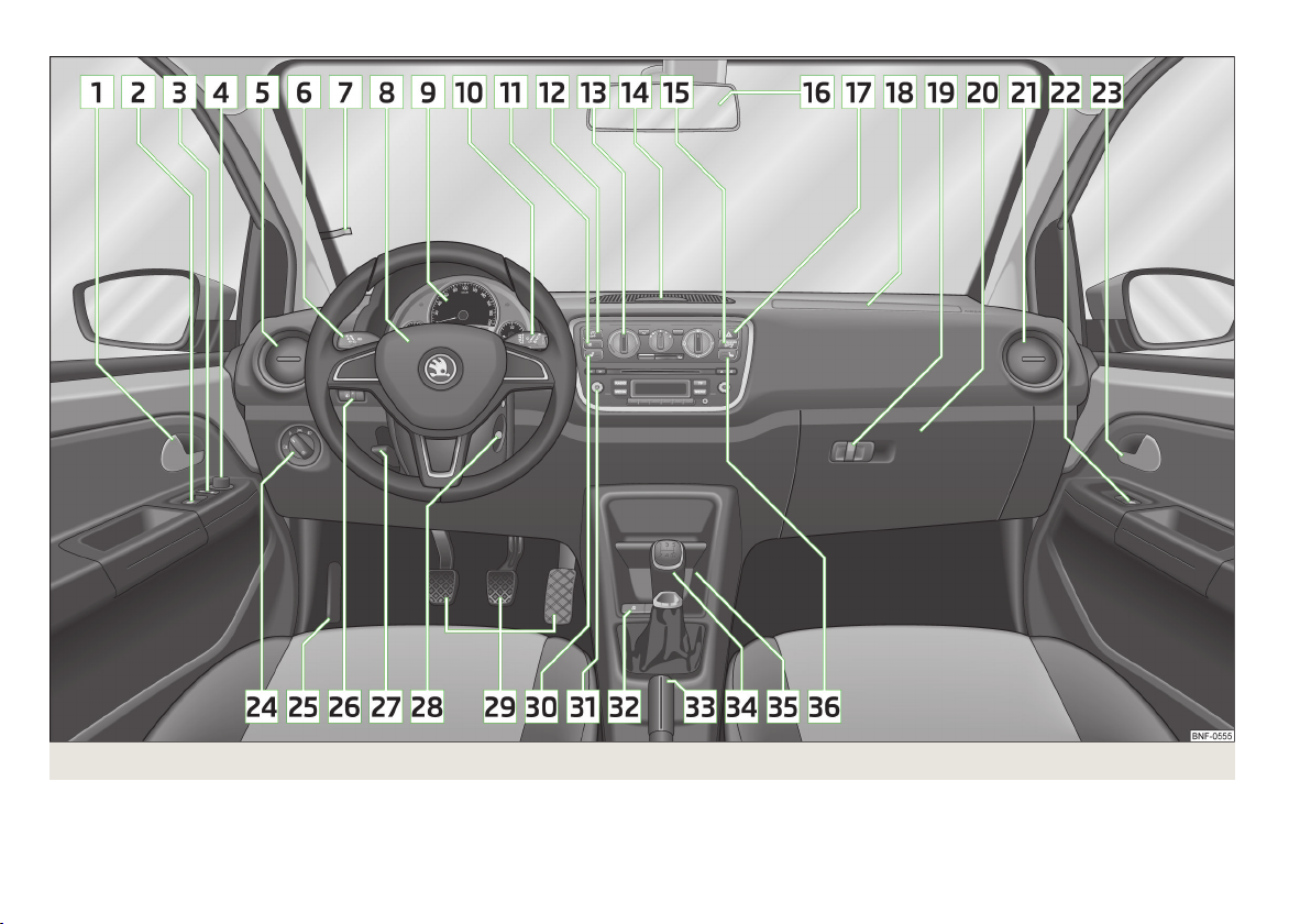
Fig. 1
8
Using the system
Cockpit
Page 12
Using the system
Cockpit
Overview
1
Door opening lever 24
2
Electrical power window in the driver's door 30
3
Central locking system 27
4
Electric exterior mirror adjustment 41
5
Air outlet vent 57
6
Operating lever:
Turn signal lights and main beam, headlight flasher 34
›
Speed regulating system
›
7
Parking ticket holder 53
8
Steering wheel:
With horn
›
With driver’s front airbag
›
9
Instrument cluster: Instruments and warning lights
10
Operating lever:
Multifunction display
›
Windscreen wiper and wash system 38
›
11
Button for rear window heater
12
START-STOP button
13
Depending on equipment fitted:
Operating controls for the heating
›
Operating controls for the air conditioning system 59
›
14
Socket for the cradle for the Move & Funmultifunction device.
15
Warning light for the deactivated front seat passenger airbag
16
Interior rear-view mirror 40
17
Button for hazard warning light system
18
Front passenger airbag 99
19
Bag holder
20
Storage compartment on the front passenger side
21
Air outlet vent 57
22
Power window in the front passenger door 30
23
Door opening lever 24
24
Light switch 33
25
Bonnet release lever 127
26
Regulator for headlamp beam adjustment for the headlights 34
27
Lever for adjusting the steering wheel 66
28
Ignition lock 68
29
Pedals 71
30
Regulator for left seat heating 44
31
Radio
32
Button for City Safe Drive system
33
Handbrake lever 70
34
Depending on equipment fitted:
Gearshift lever (manual gearbox) 70
›
Selector lever (automated gearbox)
83
99
10
13
37
85
58
64
102
36
55
54
›
35
Storage compartment 55
36
Regulator for right seat heating
Note
■
Cars with factory-fitted radio are supplied with separate instructions for operat-
ing such equipment.
■
The arrangement of the controls and switches and the location of some items
on right-hand drive models may differ from that shown in » Fig. 1 . The symbols on
the controls and switches are the same as for left-hand drive models.
86
71
44
Cockpit
9
Page 13
warning lights and instruments
Instrument cluster
Introduction
This chapter contains information on the following subjects:
Overview
Speedometer 11
Fuel gauge 11
Engine revolutions counter 11
Counter for distance driven 12
Service Interval Display 12
Recommended gear
WARNING
■
Concentrate fully at all times on your driving! As the driver you are fully re-
sponsible for road safety.
■
Never operate the controls in the instrument cluster while driving, only
when the vehicle is stationary!
Overview
10
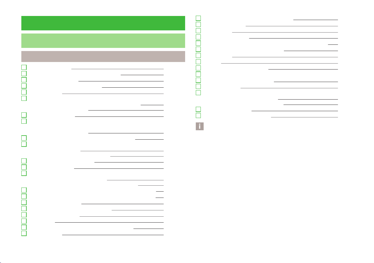
Fig. 2 Instrument cluster - Version 1
12
Instrument cluster - Version 2
Fig. 3
10
Using the system
First read and observe the introductory information and safety warnings on page 10.
1
Speedometer » page 11
2
Display:
With counter for distance driven » page 12
›
with outside temperature display » page 14
›
Page 14

With service interval display » page 12
›
With multifunction display » page 13
›
with fuel reserve gauge (option 1 only) » page 11
›
3
Reset button for the display of the daily trip counter (trip) » page 12
4
Fuel gauge » page 11
5
Engine revolutions counter » page 11
6
Adjust button for the clock » page 14
Speedometer
First read and observe the introductory information and safety warnings
The speed is shown in km/h or mph and km/h depending on the vehicle.
on page 10.
Fuel gauge
Fuel gauge
Fig. 4
First read and observe the introductory information and safety warnings on page 10.
Vehicles running on petrol
The fuel gauge » Fig. 4 only operates if the ignition is switched on.
The fuel tank has a capacity of about 35 litres. If the fuel gauge in the fuel tank
reaches the reserve capacity level, the warning symbol of on » Fig. 4 - will
appear in the instrument cluster or the symbol will flash for 10 seconds together with the remaining segments in the instrument cluster display » Fig. 4 - .
There are now about 4 litres of fuel remaining in the tank.
An audible signal sounds as a warning signal.
Vehicles running on CNG (compressed natural gas)
The fuel gauge » Fig. 5 only operates if the ignition is switched on.
When the vehicle runs on petrol, the pointer of the fuel gauge is in the range
1
» Fig. 5. When the vehicle runs on CNG, the pointer of the fuel gauge is in the
range 2.
If the fuel level in the fuel tank reaches the reserve area for petrol, the warning
light goes on. The pointer is in the red range of the gauge
now about 5 l of fuel remaining in the tank.
If the fuel level in the fuel tank for CNG reaches the reserve area, the indicator
lights up. The pointer is in the red range of the gauge 2 » Fig. 5. There are now
about 1.5 kg of fuel remaining in the tank.
1
» Fig. 5. There are
CAUTION
Never drive until the fuel tank is completely empty! The irregular supply of fuel
can cause misfiring. This can result in considerable damage to parts of the engine
and the exhaust system.
Fig. 5
Fuel gauge - CNG
Engine revolutions counter
First read and observe the introductory information and safety warnings on page 10.
The red scale of the rev counter 5 » Fig. 3 on page 10 indicates the range in
which the system begins to limit the engine speed. The system automatically restricts the engine speed to a steady limit.
Before reaching the red zone of the rev counter scale, shift up into the next higher gear.
warning lights and instruments
11
Page 15

Follow the recommended gear to prevent engine speeds that are too high or too
low » page 12.
Avoid high engine speeds during the running-in period and before the engine has
warmed up to the operating temperature .
For the sake of the environment
Correct shifting up has the following advantages.
■
It helps to reduce fuel consumption.
■
It reduces the operating noise.
■
It protects the environment.
■
It benefits the durability and reliability of the engine.
Counter for distance driven
First read and observe the introductory information and safety warnings on page 10.
To toggle between the odometer and the daily trip counter, briefly press the button 3 » Fig. 2 on page 10 or » Fig. 3 on page 10 .
Daily trip counter (trip)
The daily trip counter indicates the distance which you have driven since it was
last reset - in steps of 100 metres or 1/10 of a mile.
Reset trip counter for the distance driven
Press and hold the 3 » Fig. 2 on page 10 or » Fig. 3 on page 10 button.
›
Odometer
The odometer indicates the total distance which the vehicle has been driven.
Service Interval Display
First read and observe the introductory information and safety warnings on page 10.
Before the next service interval, the message
ter display for some seconds and the remaining kilometres are indicated after
switching on the ignition.
At the time of the service, an acoustic signal will sound and the message
pears for a few seconds after switching on the ignition.
appears in the instrument clus-
ap-
Note
■
Information is retained in the Service Interval Display even after the vehicle bat-
tery is disconnected.
■
If the instrument cluster is exchanged after a repair, the correct values must be
entered in the counter for the Service Interval Display. This work is carried out by
a specialist garage.
■
For more information on the service intervals » page 108, Service intervals.
Recommended gear
First read and observe the introductory information and safety warn-
on page 10.
ings
An information for the engaged gear is shown in the display of the instrument
cluster.
In order to minimise the fuel consumption, a recommendation for shifting into another gear is indicated in the display.
Show Importance
Optimal gear.
Recommends that you shift to a higher gear.
Recommends that you shift to a lower gear.
CAUTION
The driver is always responsible for selecting the correct gear in different driving
situations, such as overtaking.
12
Using the system
Page 16

Multifunction display (MFA)
Memory
Introduction
This chapter contains information on the following subjects:
Memory
Operation 14
Digital clock 14
Multifunction display details 14
Warning against excessive speeds 15
The driving data is displayed on the multifunction display.
The multifunction display can only be operated when the ignition is switched on.
After the ignition is switched on, the function displayed is the one which you last
selected before switching off the ignition.
WARNING
■
Concentrate fully at all times on your driving! As the driver you are fully re-
sponsible for the operation of your vehicle.
■
Even at temperatures of around +4 °C, black ice may still be on the road surface! You should therefore not only rely on the outside temperature display
for accurate information as to whether there is ice on the road.
Note
In certain national versions the displays appear in the Imperial system of measures.
Fig. 6
Multi-function display - Display
example of the memory
13
First read and observe the introductory information and safety warnings on page 13.
The multifunction display is equipped with two automatic memories, 1 and 2. The
selected memory is shown in the Display » Fig. 6 .
Exchange between memories is made with the B button on the wiper
stalk » Fig. 7 on page 14.
Single-trip memory (memory 1)
The single-trip memory collates the driving information from the moment the ignition is switched on until it is switched off. New data will also flow into the calculation of the current driving information if the trip is continued within 2 hours
after switching off the ignition. If the trip is interrupted for more than 2 hours,
the memory is automatically erased.
Total-trip memory (memory 2)
The total distance driven memory gathers data from any number of individual
journeys up to a total of 19 hours and 59 minutes driving or 1,999 kilometres driven. The memory is deleted when either of these limits is reached and the calculation starts all over again.
Unlike the single-trip memory, the total-trip memory is not deleted after a period
of interruption of driving of 2 hours.
Note
All information in the memory
connected.
1 and 2 is erased if the battery of the vehicle is dis-
warning lights and instruments
13
Page 17

Operation
Fig. 7
Buttons on the control lever
First read and observe the introductory information and safety warnings on page 13.
The Toggle button for selecting menu items A and B are located on the control
button on the wiper stalk » Fig. 7.
Select menu items
Briefly press the rocker switch A » Fig. 7 up or down. This opens the individual
›
functions of the multifunction display one after the other.
Select memory
Press the button B » Fig. 7 .
›
Reset memory
Select the desired memory.
›
Press the button B » Fig. 7 longer.
›
With the
zero.
›
›
›
›
B
button, the following values of the selected memory are set to
Average fuel consumption
Distance travelled
Average speed
Driving time
Digital clock
First read and observe the introductory information and safety warnings on page 13.
The time is set as follows:
Press the rocker switch A » Fig. 7 on page 14 up or down to change the display
›
of the time.
Press the button 6 » Fig. 3 on page 10 to select the hour display so that it
›
flashes.
Press button3 to continue setting the time. Keep the button pressed to run
›
through the numbers quickly.
Press the button6 to select the minutes display so that it flashes.
›
Press button3 to continue setting the time. Keep the button pressed to run
›
through the numbers quickly.
Confirm the set value by pressing the button6 again, or wait for around 5 sec-
›
onds. The setting is saved automatically (the value stops flashing).
Multifunction display details
First read and observe the introductory information and safety warnings on page 13.
Outside temperature
The current outside temperature is displayed.
If the outside temperature drops below +4 °C, the temperature indicator appears
and a snow flake symbol (black ice warning) flashes for a few seconds, then remains displayed together with the outside temperature.
Driving time
The driving time which has elapsed since the memory was last erased appears in
the display. If you want to measure the time travelled from a particular moment in
time, reset the memory to zero at that point in time » page 13.
The maximum distance indicated in both memories is 19 hours and 59 minutes.
The indicator is set back to zero if this period is exceeded.
14
Using the system
Page 18

Current fuel consumption
The current fuel consumption level is displayed in litres/100 km1). You can use this
information to adapt your driving style to the desired fuel consumption.
The display appears in litres/hour if the vehicle is stationary or driving at a low
speed2).
Average fuel consumption
The average fuel consumption since the memory was last erased is displayed in
litres/100 km
If you wish to determine the average fuel consumption over a certain period of
time, you must set the memory at the start of the new measurement to
zero » page 13. After erasing the memory, no value is displayed until you have
driven approx. 300 m.
The display is updated regularly while you are driving.
Range
The estimated range is displayed in kilometres. It indicates the distance you can
still drive with your vehicle based on the level of fuel in the tank and the same
style of driving.
The display is shown in steps of 10 km. After lighting up of the warning light for
the fuel reserve the display is shown in steps of 5 km.
The fuel consumption over the last 50 km is used to calculate the information.
The range will increase if you drive in a more economical manner.
Distance travelled
The distance travelled since the memory was last erased is displayed » page 13. If
you want to measure the distance travelled from a particular moment in time, reset the memory to zero at that moment in time » page 13.
The maximum distance indicated in both memories is 1 999 km. The indicator is
set back to zero if this period is exceeded.
Average speed
The average speed since the memory was last erased is displayed in km/hour . To
determine the average speed over a certain period of time, set the memory to
zero at the start of the measurement » page 13.
1 )
.
After erasing this data, no value appears in the display until you have driven approx. 300 m.
The display is updated regularly while you are driving.
Current speed
The current speed, which is identical to the display of the speedometer 1 » Fig. 3
on page 10 is displayed.
Coolant temperature
The current outside temperature is displayed.
Warning against excessive speeds
The warning that the speed limit is being exceeded can be enabled / disabled » page 15, Warning against excessive speeds in the display.
Warning against excessive speeds
First read and observe the introductory information and safety warnings
Adjust the speed limit while the vehicle is stationary
With button A » Fig. 7 on page 14 choose the menu point Warning against
›
excessive speeds.
Press the button B to activate the ability to set the speed limit (value flashes).
›
Use the button A to set the required speed limit, e.g. 50 km/h.
›
Confirm the speed limit that was set with button B, or wait approx. 5 seconds
›
until the setting is saved automatically (the value stops flashing).
This allows you to set the speed in 5 km/h intervals.
Adjusting the speed limit while the vehicle is moving
With button A » Fig. 7 on page 14 choose the menu point Warning against
›
excessive speeds.
Drive at the desired speed, e.g. 50 km/h.
›
Press button B to accept the current speed as the speed limit (the value flash-
›
es).
If you wish to adjust the set speed limit, you can do so in 5 km/h intervals (e.g. the
accepted speed of 47 km/h increases to 50 km/h or decreases to 45 km/h).
on page 13.
1)
On some models in certain countries, the display appears in kilometres/litre.
2)
On some models in certain countries, the display appears in --,- kilometres/litres if the vehicle is stationary.
warning lights and instruments
15
Page 19

Confirm the speed limit that was set by pressing button B again, or wait ap-
›
prox. 5 seconds until the setting is saved automatically (the value stops flashing).
Change or delete speed limit
With button A » Fig. 7 on page 14 choose the menu point Warning against
›
excessive speeds.
Pressing button B deletes the speed limit.
›
Pressing the button B activates the ability to change the speed limit.
›
If the set speed limit is exceeded, an audible signal will sound as a warning. At
the same time the message (warning against excessive speed) appears on the
display with the set limit value.
The set driving mode remains stored even after switching the ignition on and off.
Warning lights
Introduction
This chapter contains information on the following subjects:
Handbrake
Braking system
Seat belt warning light 17
Generator 17
Engine oil 17
Coolant
Power steering 18
Electronic Stability Control (ESC) 18
Traction Control System (TC)
Antilock brake system (ABS)
The rear fog light
Exhaust inspection system
EPC fault light
Airbag system
Automated transmission
Turn signal system
Cruise control system
Main beam
/ Safety belt (belt status display) - rear seat 21
City Safe Drive
START STOP 21
The warning lights show certain functions/faults and may be accompanied by
audible signals.
WARNING
■
If illuminated warning lights and the corresponding descriptions and warning notes are not observed, this may result in severe injuries or major vehicle
damage.
■
The engine compartment of your car is a hazardous area. There is a risk of
injuries, scalding, accidents and fire when working in the engine compartment, e.g. inspecting and replenishing oil and other fluids. It is essential to observe safety notes » page 127, Engine compartment.
Handbrake
First read and observe the introductory information and safety warnings
16
The warning light comes on if the handbrake is applied. An audible warning is
16
also given if you drive the vehicle for at least 3 seconds at a speed of more than
6 km/h.
18
19
19
19
19
19
20
20
20
21
21
Braking system
The warning light illuminates if the brake fluid level is too low or there is a
fault in the ABS.
Stop the vehicle, switch off the engine, and check the level of the brake fluid » page 133.
Further information » page 68.
on page 16.
First read and observe the introductory information and safety warnings on page 16.
21
16
Using the system
Page 20

WARNING
■
If you have to stop for technical reasons, then park the vehicle at a safe distance from the traffic, switch off the engine and activate the hazard warning
light system » page 36.
■
The following guidelines should be observed when opening the bonnet and
checking the brake fluid level » page 127, Engine compartment.
■
If the warning light is displayed simultaneously with warning light
» page 19, Antilock brake system (ABS), do not continue your jour-
ney! Seek help from a specialist garage.
■
A fault to the braking system can increase the vehicle's braking distance!
Seat belt warning light
First read and observe the introductory information and safety warnings on page 16.
The warning light comes on after the ignition is switched on as a reminder for
the driver and front passenger to fasten the seat belt. The warning light only
goes out if the driver or front passenger has fastened his seat belt.
If the seat belt has not been fastened by the driver or front passenger, a permanent warning signal sounds at vehicle speeds greater than 25 km/h and simultaneously the warning light flashes.
If the seat belt is not fastened by the driver or front passenger during the next
90 seconds, the warning signal is deactivated and the warning light lights up
permanently.
Further information » page 94, Seat belts.
Generator
First read and observe the introductory information and safety warnings on page 16.
If the warning light lights up when the engine is running, the vehicle battery is
not being charged.
Seek help from a specialist garage. The electrical system requires checking.
WARNING
If you have to stop for technical reasons, then park the vehicle at a safe distance from the traffic, switch off the engine and activate the hazard warning
lights » page 36.
CAUTION
If the warning light (cooling system fault) comes on in addition to the warning
light in the display when driving, stop the vehicle immediately and switch the
engine off – risk of engine damage!
Engine oil
First read and observe the introductory information and safety warnings on page 16.
When the indicator light is flashing , the engine oil pressure is too low.
The warning light comes on for a few seconds when the ignition is switched on.
Stop the vehicle and switch the engine off if the warning light does not go off
after the engine has started or flashes while driving. Check the oil level and top
up with engine oil if necessary » page 131, Checking the oil level.
An audible signal sounds as a warning signal.
Do not continue your journey if for some reason it is not possible to top up the
engine oil under the prevailing conditions. This can cause serious engine damage.
Therefore, switch the engine off and seek help from a specialist garage.
Even if the oil level is correct, do not drive any further if the warning light is
flashing. Also do not leave the engine running at an idling speed.
Seek help from a specialist garage.
WARNING
If you have to stop for technical reasons, then park the vehicle at a safe distance from the traffic, switch off the engine and activate the hazard warning
light system » page 36, Hazard warning light system.
warning lights and instruments
17
Page 21

CAUTION
The red oil pressure light is not an oil level indicator! One should therefore
check the oil level at regular intervals, preferably after every refuelling stop.
Coolant
First read and observe the introductory information and safety warnings on page 16.
The warning light comes on for a few seconds when the ignition is switched
on.
If the warning light lights up or flashes, either the coolant temperature is too
high or the coolant level is too low.
An audible signal sounds as a warning tone.
Stop the vehicle, switch off the engine, check the level of the coolant » page 132,
and refill the coolant if necessary » page 133.
Do not continue your journey if for some reason it is not possible to top up the
coolant under the prevailing conditions. This can cause serious engine damage.
Therefore, switch the engine off and seek help from a specialist garage.
If the coolant is within the specified range, the increased temperature may be
caused by an operating problem at the radiator fan. Check the fuse for the radiator fan, replace if necessary » page 156, Fuses in the engine compartment.
Do not continue driving if the warning light does not go off even though the
coolant level is correct and the fuse for the fan is in working order!
Seek help from a specialist garage.
WARNING
If you have to stop for technical reasons, then park the vehicle at a safe distance from the traffic, switch off the engine and activate the hazard warning
lights » page 36.
Power steering
First read and observe the introductory information and safety warnings on page 16.
The warning light comes on for a few seconds when the ignition is switched
on.
If the warning light after switching on the ignition or when driving lights up continuously, a fault exists in the electromechanical power steering.
If the yellow warning light lights up , this indicates a partial failure of the
›
power steering and the steering forces can be greater.
If the red warning light lights up , this indicates a complete failure of the pow-
›
er steering and the steering assist has failed (significantly higher steering
forces).
Further information » page 66.
Note
■
If the yellow warning light goes out after starting the engine again and driv-
ing a short distance, it is not necessary to visit a specialist garage.
■
If the vehicle battery has been disconnected and reconnected, the yellow warning light comes on after switching on the ignition. The warning light should go
out after driving a short distance.
Electronic Stability Control (ESC)
First read and observe the introductory information and safety warnings on page 16.
The warning light flashes to show that the ESC is currently operating.
If the warning light lights up, there is a fault in the ESC.
As the ESC operates in conjunction with the ABS, the ESP warning light will also
come on if the ABS system fails.
If the warning light comes on immediately after starting the engine, the ESC
can be switched off for technical reasons. In this case, the ESC can be switched
on again by switching the ignition on and off. If the warning light goes out, the
ESC is fully functional again.
Further information » page 80, Electronic Stability Control (ESC).
18
Using the system
Page 22

Note
If the vehicle's battery has been disconnected and reconnected, the warning light
comes on after switching on the ignition. The warning light should go out after
driving a short distance.
Traction Control System (TC)
First read and observe the introductory information and safety warnings on page 16.
The warning light comes on for a few seconds when the ignition is switched
on.
The warning light comes on when driving when a control cycle is activated.
The warning light illuminates permanently if there is a fault in the TCS.
The fact that the TCS operates together with the ABS means that the TCS warn-
ing light will also come on if the ABS system is not operating properly.
If the warning light comes on immediately after starting the engine, the TCS
can be switched off for technical reasons. In this case, the TCS can be switched
on again by switching the ignition on and off. If the warning light goes out, the
TCS is fully functional again.
Further information » page 81, Traction Control System (TCS).
Note
If the vehicle's battery has been disconnected and reconnected, the warning light
comes on after switching on the ignition. The warning light should go out after
driving a short distance.
Antilock brake system (ABS)
First read and observe the introductory information and safety warnings on page 16.
If the warning light lights up, there is a fault in the ABS.
The vehicle will only be braked by the normal brake system without the ABS.
Seek help from a specialist garage.
Further information » page 81, Antilock Braking System (ABS).
WARNING
■
If you have to stop for technical reasons, then park the vehicle at a safe dis-
tance from the traffic, switch off the engine and activate the hazard warning
light system » page 36.
■
If the warning light » page 16 is displayed simultaneously with the ABS
warning light , do not continue your journey! Seek help from a specialist
garage.
■
The following guidelines should be observed when opening the bonnet and
checking the brake fluid level » page 127, Engine compartment.
■
A fault to the ABS system or the braking system can increase the vehicle's
braking distance – risk of accident!
The rear fog light
First read and observe the introductory information and safety warn-
on page 16.
ings
The warning light comes on when the rear fog lights are operating » page 35.
Exhaust inspection system
First read and observe the introductory information and safety warnings
If the warning light lights up, there is a fault in the exhaust inspection system.
The engine control unit allows the vehicle to run in emergency mode.
Seek help from a specialist garage.
on page 16.
EPC fault light
First read and observe the introductory information and safety warnings on page 16.
If the warning light
control unit allows the vehicle to run in emergency mode.
Seek help from a specialist garage.
lights up, there is a fault in the engine control. The engine
warning lights and instruments
19
Page 23

Airbag system
First read and observe the introductory information and safety warnings on page 16.
Monitoring the airbag system
The warning light comes on for a few seconds when the ignition is switched
on.
There is a fault in the system if the warning light does not go out or flashes while
driving » . This also applies if the warning light does not come on when the ignition is switched on.
The operational capability of the airbag system is monitored electronically, including when one of the airbags is switched off.
The following situation applies if the front or side airbag or belt tensioner have
been switched off using the vehicle system tester:
The warning light lights up for around 4 seconds after switching on the igni-
›
tion and then flashes approximately another 12 seconds in 2 second intervals.
The following situation applies if the airbag has been switched off using the
key switch for the airbag in the front passenger storage compartment:
The warning light comes on for a few seconds when the ignition is switched
›
on;
The deactivated airbag is indicated by the illumination of the warning light
›
the front passenger airbag.
in the middle of the dash panel » page 102, Deactivating
WARNING
If there is a fault, have the airbag system checked immediately by a specialist
garage. Otherwise, there is a risk that the airbag will not be deployed in the
event of an accident.
Warning light
Do not continue your journey if the warning light lights up and an acoustic signal sounds. Switch off the engine and seek assistance from a specialist garage.
Automated transmission
First read and observe the introductory information and safety warnings on page 16.
Warning light
If the warning light lights up and no gear can be selected, switch the ignition
on and off. If the warning light lights up after you switch on the ignition, seek assistance from a specialist garage.
If the warning light or warning light lights up and an acoustic signal sounds,
this means that the automatic gearbox has overheated. Stop and allow the transmission to cool down or drive more quickly than 20 km/h (12 mph).
If the warning light lights up again, switch off the vehicle, shut off the engine
and allow the gearbox to cool down.
Warning light
If the warning light lights up, operate the brake pedal.
Warning light
If the warning light lights up, operate the handbrake. Further information » page 71, Automated transmission.
WARNING
If you have to stop for technical reasons, then park the vehicle at a safe dis-
tance from the traffic, switch off the engine and activate the hazard warning
lights » page 36.
Turn signal system
First read and observe the introductory information and safety warnings
Either the left or right warning light flashes depending on the position of the
turn signal lever.
If a turn signal light fails, the warning light flashes at twice its normal rate.
Switching off the hazard warning light system is switched on will cause all of the
turn signal lights as well as both warning lights to flash.
Further information » page 34, Turn signal and main beam.
on page 16.
20
Using the system
Page 24

Cruise control system
First read and observe the introductory information and safety warnings on page 16.
The warning light comes on when the cruise control is operating » page 83.
Main beam
First read and observe the introductory information and safety warnings
The warning light comes on when the main beam or headlight flasher are selected » page 33.
/ Safety belt (belt status display) - rear seat
After switching on the ignition, the belt status warning lights up for the rear
seats in the instrument panel display for 30 seconds and indicates whether any
rear seat passengers have fastened their seat belts. The belt status indicator will
then light up when the passenger on the rear seat fastens or unfastens the seat
belt (when the ignition is switched on or during the journey).
If the warning light , is switched on, the passenger on the rear seat has their
seat belt on.
If the warning light , is switched on, the passenger on the rear seat does not
have their seat belt on.
If a seat belt is unfastened on the rear seat during the journey at a speed of more
than 25 km/h, an acoustic signal will sound, and the belt status indicator for the
rear seats will flash for around 30 seconds.
Further information » page 94, Seat belts.
on page 16.
First read and observe the introductory information and safety warnings on page 16.
City Safe Drive
First read and observe the introductory information and safety warnings on page 16.
If the City Safe Drive system is currently slowing the vehicle down automatically,
the warning light will flash quickly.
If the City Safe Drive system is not currently available, or if there is a system fault,
the warning light will flash slowly.
When the City Safe Drive system is switched off while the vehicle is travelling at a
speed between 5–30 km/h (3-19 mph), the warning light will light up in the
instrument cluster display.
If the City Safe Drive system is switched on, the warning light in the instrument
cluster display
Further information » page 86, City Safe Drive.
START STOP
If the START STOP system is active, the warning light will light up .
If the START STOP system is active, but automatic engine shut down is not possi-
ble, the warning light will light up .
When the warning light flashes the START STOP system will not be available.
Further information » page 85, START-STOP.
will light up for around 5 seconds.
First read and observe the introductory information and safety warn-
on page 16.
ings
warning lights and instruments
21
Page 25

Unlocking and locking
Unlocking and locking
Introduction
This chapter contains information on the following subjects:
Vehicle key
Replacing the battery in the remote control key 23
Child safety lock 23
Opening/closing a door 24
Door opening lever 24
Emergency locking of the doors 25
Vehicle key
Fig. 8
Key: without/with remote control
First read and observe the introductory information given on page 22.
22
Two keys are provided with the vehicle » Fig. 8.
Keys without remote control
Keys with remote control (remote control keys)
WARNING
■
Always withdraw the key whenever you leave the vehicle – even if it is only
for a short time. This is particularly important if children are left in the vehicle.
The children might otherwise start the engine or operate electrical equipment
(e.g. power windows) – risk of injury!
■
Do not withdraw the ignition key from the ignition lock until the vehicle has
come to a stop. The steering lock might otherwise engage unintentionally –
risk of accident!
CAUTION
■
Each key contains electronic components; therefore it must be protected
against moisture and severe shocks.
■
Keep the groove of the keys absolutely clean. Impurities (textile fibres, dust,
etc.) have a negative effect on the functionality of the locking cylinder and ignition lock.
■
The function of the remote control may temporarily be affected by interference
from transmitters located near the vehicle that operate in the same frequency
range (e.g. mobile phones, television transmitters).
■
The battery must be replaced if the central locking does react to the remote
control at less than around 3 metres away » page 23.
Note
If you lose a key, please contact a specialist garage, who will be able to provide
you with a new one.
22
Using the system
Page 26
Replacing the battery in the remote control key
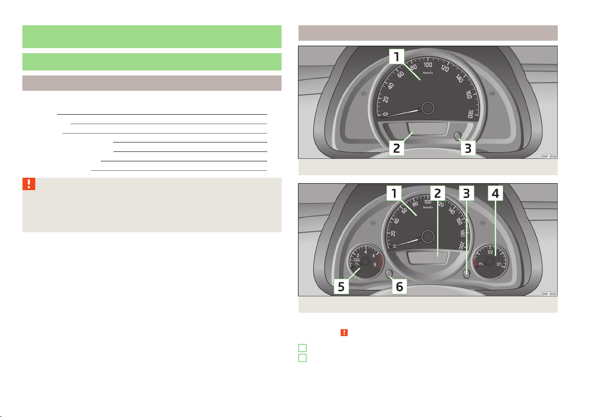
Fig. 9 Remote control key: Remove cover/remove battery
First read and observe the introductory information given on page 22.
Each remote control key contains a battery which is housed under the cover
B
» Fig. 9. The battery needs replacing if red indicator light » Fig. 8 on page 22 -
does not go on when you press a button on the remote control key. We recommend having the key batteries replaced by a specialist garage. However, if you
would like to replace the discharged battery yourself proceed as follows.
Flip out the key.
›
Press off the battery cover with your thumb or using a flat screwdriver in the
›
region of arrows 1 » Fig. 9.
Remove the discharged battery from the key by pressing the battery down-
›
wards in the region of arrow
Insert the new battery. Ensure that the “+” symbol on the battery is facing up-
›
wards. The correct polarity is shown on the battery cover.
Place the battery cover on the key and press it down until it clicks into place.
›
CAUTION
■
Pay attention to the correct polarity when changing the battery.
■
The replacement battery must have the same specification as the original bat-
tery.
2
.
Note
■
The system has to be synchronised, if the vehicle cannot be unlocked or locked
with the remote control key after replacing the battery » page 28.
■
If a key has an affixed decorative cover, this will be destroyed when the battery
is replaced. A replacement cover can be purchased from a ŠKODA Partner.
Child safety lock
Fig. 10
Parental Control: Left rear door
First read and observe the introductory information given on page 22.
The child safety lock prevents the corresponding rear door from being opened
from the inside. The door can only be opened from the outside.
You can switch the child safety lock on and off using the vehicle key.
Switching on
Turn the slot of the safety lock in the direction of the arrow » Fig. 10 (mirror-
›
inverted on the right doors).
Switching off
Turn the slot of the safety lock in the opposite direction to the arrow » Fig. 10
›
(mirror-inverted on the right door).
For the sake of the environment
Dispose of the used battery in accordance with national legal provisions.
Unlocking and locking
23
Page 27
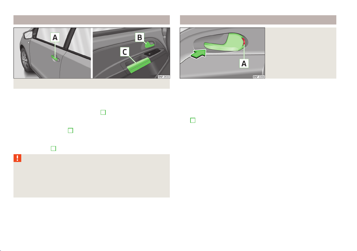
Opening/closing a door
Door opening lever
Fig. 12
Door opening lever
Fig. 11 Door handle/door opening lever:
First read and observe the introductory information given on page 22.
Opening from the outside
Unlock the vehicle and pull the door handle A » Fig. 11 on the door you wish to
›
open.
Opening from the inside
Pull on door opening lever B of the respective door and push the door away
›
from you.
Closing from the inside
Grasp pull handle C and close the door.
›
WARNING
■
Make sure that the door has closed correctly as it can open suddenly while
driving – risk of death!
■
Only open and close the door when there is no one in the opening/closing
range – risk of injury!
■
An opened door can close automatically if there is a strong wind or the vehi-
cle is on an incline – risk of injury!
24
Using the system
First read and observe the introductory information given on page 22.
On vehicles without central locking, you can lock and unlock doors which do not
have a locking cylinder from the inside.
Locking
Push the door opening lever in the direction of the arrow so that the red mark-
›
A
ing
» Fig. 12 is visible.
Unlocking
Open the door by pulling the door opening lever once against the direction of
›
the arrow » Fig. 12 .
Page 28

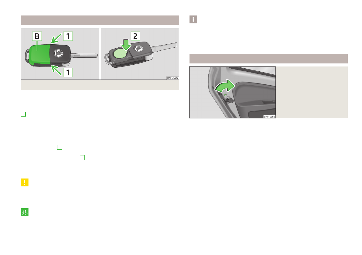
Emergency locking of the doors
Fig. 13 Emergency locking of the door
First read and observe the introductory information given on page 22.
An emergency locking mechanism is located on the front of the doors that have
no locking cylinder » Fig. 13 - , this mechanism is only visible after opening the
door.
Locking
Insert the key into the slot » Fig. 13 - and turn it in the horizontal position at
›
the right door arrow » Fig. 13 - in the arrow direction and turn against the arrow direction with the left door.
After closing the door, it no longer be opened from the outside. The door can be
unlocked from the inside by pulling on the door handle again, and then opened
from the outside.
Central locking system
Introduction
This chapter contains information on the following subjects:
Safe securing system 26
Unlocking the vehicle using the key 26
Locking the vehicle with the key
Vehicle locking/unlocking from the inside
26
In setting up and locking, all doors are unlocked or locked together by the central
locking system. The boot lid is unlocked. The luggage compartment lid can then
be opened by pressing the button.
Automatic locking and unlocking
All the doors and the luggage compartment lid are locked automatically once the
car reaches a speed of about 15 km/h.
If the ignition key is withdrawn, the car is then automatically unlocked again. It is
also possible for the driver to unlock the car by pressing the central locking button.
The doors can be unlocked and opened from the inside by a single pull on the
opening lever of the respective door.
Automatic locking and unlocking can be activated by a specialist garage on request.
WARNING
Locked doors prevent unwanted entry into the vehicle from outside, for example at road crossings. They do, however, make it more difficult for rescuers to
get into the vehicle in an emergency – risk to life!
Note
■
In the event of an accident in which the airbags are deployed, the locked doors
are automatically unlocked in order to enable rescuers to gain access to the vehicle.
■
In case the key fails to operate the central locking, only the driver's door can be
unlocked or locked. The other doors and the tailgate can be manually locked or
unlocked.
■
Emergency locking of the door » page 25.
■
Emergency unlocking of the luggage compartment lid » page 29.
27
Unlocking and locking
25
Page 29

Safe securing system
First read and observe the introductory information and safety warnings on page 25.
The central locking system is equipped with a safe securing system. The door
locks are blocked automatically if the vehicle is locked from the outside. The
warning light flashes for around 2 seconds in quick succession, afterwards it begins to flash evenly at longer intervals. It is not possible to open the doors with
the door handle either from the inside or from the outside. This acts as an effective deterrent against attempts to break into your vehicle.
The safe securing system can be deactivated within 2 seconds by double locking
the vehicle.
If the safe securing system is not operating, the warning light in the driver door
flashes for about 2 seconds fast, goes out and starts to flash evenly at longer intervals after about 30 seconds.
The safe securing system is activated again the next time the vehicle is unlocked
and locked.
If the vehicle is locked and the safe securing system is deactivated, the door can
be opened from the inside by a single pull on opening lever of the respective
door.
WARNING
If the vehicle is locked from the outside and the safe securing system is activated, there must not be any person in the vehicle as it is then no longer possible to open either a door or a window from the inside. The locked doors
make it more difficult for rescuers to get into the vehicle in an emergency –
risk to life!
Note
You will be informed that the safe securing system has been activated after the
vehicle has been locked by means of the message on the instrument cluster display.
Unlocking the vehicle using the key
Fig. 14
Left side of the vehicle: Turning
the key for unlocking and locking the vehicle
First read and observe the introductory information and safety warnings on page 25.
Turn the key in the locking cylinder of the driver's door in the direction of travel
›
(unlocking position) A » Fig. 14.
Pull the door handle and open the door.
›
All the doors are unlocked.
›
The luggage compartment lid is then unlocked.
›
The switched on interior lights come on over the door contact.
›
The safe securing system is deactivated.
›
Locking the vehicle with the key
First read and observe the introductory information and safety warnings on page 25.
Turn the key in the locking cylinder of the driver's door in the opposite direction
›
of travel (lock position) B » Fig. 14 on page 26.
All the doors and the luggage compartment lid are locked.
›
The switched on interior lights will switch off over the door contact.
›
The safe securing system is immediately activated.
›
The warning light in the driver door begins flashing.
›
Note
If the driver's door has been opened, the vehicle cannot be locked.
26
Using the system
Page 30

Vehicle locking/unlocking from the inside
Fig. 15
Central locking button
First read and observe the introductory information and safety warnings on page 25.
If the vehicle was not locked from the outside, you can also unlock or lock it with
the button » Fig. 15 , even without the ignition being switched on.
Locking
Press the symbol » Fig. 15 key.
›
Unlocking
Press the symbol key.
›
The following applies if your vehicle has been locked using the central locking
button.
It is not possible to open the doors or the luggage compartment lid from the
›
outside (safety feature, e.g. when stopping at traffic lights etc.).
The doors can be unlocked and opened from the inside by a single pull on the
›
opening lever of the respective door.
If at least one door has been opened, the vehicle cannot be locked.
›
In the event of an accident in which the airbags are deployed, the locked doors
›
are automatically unlocked from the inside in order to enable rescuers to gain
access to the vehicle.
WARNING
■
The central locking system also operates if the ignition is switched off. Children should never be left unattended in the vehicle since it is difficult to provide assistance from the outside when the doors are locked.
■
Doors locked from the inside make it difficult for rescuers to get into the vehicle in an emergency – risk to life!
Note
If the safe securing system is activated » page 26, the door opening lever and the
central locking buttons do not operate.
Remote control
Introduction
This chapter contains information on the following subjects:
Unlocking / locking
Synchronization 28
With the remote control key, the vehicle can be locked or unlocked and the boot
lid unlocked.
The transmitter with the battery is housed in the handle of the remote control
key. The receiver is located in the interior of the vehicle. The operating range of
the remote control key is approx. 30 m. But this range of the remote control can
be reduced if the batteries are weak.
The key has a fold-open key bit which can be used for unlocking and locking the
car manually and also for starting the engine.
If a lost key is replaced or if the receiver unit has been repaired or replaced, the
system must be initialised by a specialist garage. Only then can the remote control key be used again.
Note
■
The remote control is automatically deactivated when the ignition is switched
on.
■
The operation of the remote control may temporarily be affected by interference from transmitters close to the car and which operate in the same frequency
range (e.g. mobile phone, TV transmitter).
■
The battery must be replaced if the central locking or anti-theft alarm system
does react to the remote control at less than 3 metres away » page 23.
■
If the driver door is open, the vehicle cannot be locked using the remote control
key.
28
Unlocking and locking
27
Page 31

Unlocking / locking
Fig. 16
Remote control key
First read and observe the introductory information given on page 27.
Explanation of graphic
Unlocking the vehicle
Locking the vehicle
Unlocking the boot lid
A
Folding out/folding up of the key bit
B
Warning light
Unlocking
The turn signal lights flash twice as confirmation that the vehicle has been unlocked. If the vehicle is unlocked using button
luggage compartment lid are opened within the next 30 seconds, the vehicle is
automatically locked again and the safe securing system is reactivated. This function is intended to prevent the car being unlocked unintentionally.
Locking
The turn signal lights flash once to confirm that the vehicle has been correctly
locked.
If the doors or the luggage compartment lid remain open after the vehicle has
been locked, the turn signal lights do not flash until they have been closed.
WARNING
If the car is locked from the outside and the safe securing system is activated,
there must not be any person in the car as it is then not possible to open either a door or a window from the inside. The locked doors make it more difficult for rescuers to get into the vehicle in an emergency – risk to life!
1
and none of the doors or the
Note
Only operate the remote control when the doors and luggage compartment lid
are closed and the vehicle is in your line of sight.
Synchronization
First read and observe the introductory information given on page 27.
If the vehicle does not unlock when pressing the remote control, the key may not
be synchronised. This can occur when the buttons on the remote control key are
actuated a number of times outside of the operative range of the equipment or
the battery in the remote control key was replaced.
Synchronise the key as follows.
Press any button on the remote control key.
›
Pressing of the button means that the door will unlock with the key within 1 mi-
›
nute.
Luggage compartment lid
Introduction
This chapter contains information on the following subjects:
Unlocking/opening and closing 29
Automatic locking 29
Emergency unlocking 29
WARNING
■
Ensure that the lock is properly engaged after closing the luggage compart-
ment lid. Otherwise, the luggage compartment lid might open suddenly while
driving, even if the luggage compartment lid lock was closed – risk of accident!
■
Never drive with the luggage compartment lid open or ajar, as otherwise ex-
haust gases may get into the interior of the vehicle – risk of poisoning!
■
Do not press on the rear window when closing the luggage compartment lid,
as otherwise this could crack – risk of injury!
28
Using the system
Page 32

Note
A closed, but not locked luggage compartment lid is locked automatically when
driving off, or when travelling at speeds greater than about 9 km/h. It is unlocked
again after the vehicle stops and the door is opened.
Unlocking/opening and closing
Luggage compartment lid
Fig. 17
First read and observe the introductory information and safety warnings
Unlocking in vehicles without remote control
Unlock the driver's door with the vehicle key » page 26.
›
Unlocking in vehicles with remote control
Press the symbol button in the car key.
›
Unlocking with the remote control key
Press the symbol button
›
lid unlocks.
Opening
Open the luggage compartment lid by pressing the » Fig. 17 - button.
›
Closing
Reach into the recesses » Fig. 17 - and pull the luggage compartment lid
›
down.
Close the lid with a slight swing.
›
on page 28.
in the vehicle key until the luggage compartment
Automatic locking
First read and observe the introductory information and safety warnings on page 28.
If the vehicle was locked before the boot lid was closed, the lid is immediately
locked automatically when closed.
The period after which the boot lid is locked automatically can be extended by a
specialist garage.
Delayed locking
If the trunk lid was locked using the symbol button on the remote control key,
it is possible to open the tailgate within a limited period of time after it has been
closed.
There is a risk of unwanted entry into the vehicle before the boot lid is locked automatically. Therefore, the vehicle can always be locked using the symbol button of the remote control.
Delayed locking can be deactivated by a specialist garage at any time.
Note
More detailed information about this is available from a ŠKODA Partner.
Emergency unlocking
Fig. 18
Emergency unlocking of the luggage compartment lid
First read and observe the introductory information and safety warn-
ings on page 28.
The luggage compartment lid can be unlocked manually if there is a fault in the
central locking system.
Unlocking and locking
29
Page 33

Unlocking
Fold the rear seat backrest forward » page 45, Folding the rear seats forward.
›
Insert the vehicle key or a similar tool into the opening A » Fig. 18 in the lid trim
›
up to the stop.
Unlock the lock in the direction of arrow.
›
Open the boot lid.
›
Note
The heating, air conditioning and ventilation system should be used to ventilate
the inside of the vehicle while driving. If the windows are open, dust as well as
other dirt can get into the vehicle, and there may also be wind noise at certain
speeds.
Electrical power windows
Introduction
This chapter contains information on the following subjects:
Open / close window 30
Manually opening/closing rear windows
The electrical power windows can only be operated when the ignition is switched
on.
WARNING
■
If the vehicle is locked from the outside, do not leave anybody in the vehicle
as it is not possible to open the windows from the inside in the event of an
emergency.
■
When closing the windows, proceed with caution so as to avoid causing
crushing injuries - risk of injury!
CAUTION
■
Keep the windows clean to ensure the correct functionality of the electric win-
dows.
■
If the windows are frozen, first of all remove the ice » page 117, Windows and
exterior mirrors. Only then can the electrical power windows be operated, as oth-
erwise the window seal and the electrical power window mechanism could be
damaged.
■
Make sure that the windows are closed whenever you leave the locked vehicle.
For the sake of the environment
The windows must be kept closed at high speeds in order to prevent unnecessarily high fuel consumption.
Open / close window
Fig. 19
Button on the driver's door
31
First read and observe the introductory information and safety warnings on page 30.
Opening
The window is opened by pressing lightly on the corresponding button. The
›
opening process stops when one releases the button.
Closing
The window is closed by pulling lightly on the corresponding upper edge of the
›
button. The closing process stops when one releases the button.
30
Using the system
Page 34

Manually opening/closing rear windows
The sliding/tilting roof can still be operated for approx. 10 minutes after switching
the ignition off. However, as soon as one of the front doors is opened it is no longer possible to operate the sliding/tilting roof.
CAUTION
■
Always close the sliding/tilting roof before unhooking the battery.
■
If the battery has been disconnected and reconnected, it is possible that the
sliding/tilting roof does not operate correctly. Next, move the rotary switch into
position A » Fig. 21 on page 31 , pull the recess firmly downwards and hold forwards firmly. The sliding/tilting roof opens and closes again after around 10 seconds. Do not release the control dial until it has done so.
Fig. 20 Rear windows
First read and observe the introductory information and safety warnings
Opening
Take hold of the safety in the recess » Fig. 20 - and open the window in the
›
direction of the arrow.
Lock the window in the opened position by pressing the safety in the direction
›
of arrow » Fig. 20 - .
Closing
Take hold of the safety in the recess and pull it in the opposite direction of the
›
arrow » Fig. 20 - .
Close the window in the initial position in the opposite direction of the ar-
›
row » Fig. 20 - until the safety audibly latches.
on page 30.
Power sliding/tilting roof
Introduction
This chapter contains information on the following subjects:
Operation 31
The power sliding/tilting roof (abbreviated in the following as 'sliding/tilting roof'),
can only be operated with the rotary dial » Fig. 21 on page 31 when the ignition
is turned on . The control dial has several positions.
Operation
Fig. 21
Control dial for the sliding/tilting
roof
First read and observe the introductory information and safety warn-
ings on page 31.
Comfort position
Turn the switch to position C » Fig. 21 .
›
When the sliding/tilting roof is in the comfort position, the intensity of the wind
noise is reduced.
Open partially
Turn the switch to a position in area D » Fig. 21 .
›
Open fully
Turn the switch to position B » Fig. 21 and hold it in this position (spring-ten-
›
sioned position).
Tilting roof
Turn the switch to position A » Fig. 21 .
›
Unlocking and locking
31
Page 35

In order to tilt, press the switch in the region of the lug E towards the roof.
›
Closing
Turn the switch to position A » Fig. 21 .
›
To close, press the switch on the recess Edown and then push it forwards.
›
Force limiter
The sliding/tilting roof is fitted with a force limiter. The sliding/tilting roof stops
and moves back several centimetres when it cannot be closed because there is
something in the way (e.g. ice). The sliding/tilting roof can be fully closed without
a force limiter by pressing the switch on the recess down and then pushing it forward until the sliding/tilting roof is fully closed » .
WARNING
When closing the sliding/tilting roof proceed with caution to avoid causing
crushing injuries – risk of injury!
CAUTION
During the winter it may be necessary to remove any ice and snow in the vicinity
of the sliding/tilting roof before opening it to prevent any damage to the opening
mechanism.
32
Using the system
Page 36

Lights and visibility
Lights
Introduction
This chapter contains information on the following subjects:
Lights and low beam
Headlight beam adjustment 34
Daytime running light (DAY LIGHT) 34
Turn signal and main beam 34
Fog lights 35
Rear fog light 35
Hazard warning light system
Parking light 36
Unless otherwise stated, the lights only work when the ignition is on.
On models fitted with right-hand steering the position of the controls differs
from that shown in » Fig. 22 on page 33 . The symbols which mark the positions
of the controls are however identical.
WARNING
■
The activation of the lights should only be undertaken in accordance with
national legal requirements.
■
The driver is always responsible for the correct settings and use of the
lights.
■
Never drive with only the side lights on! The side lights are not bright
enough to light up the road sufficiently in front of you or to be seen by other
oncoming traffic. Therefore always switch on the low beam when it is dark or
if visibility is poor.
33
36
Note
■
The instruments are also illuminated when the side light or low beam light is
switched on.
■
The headlights may mist up temporarily. When the driving lights are switched
on, the light outlet surfaces are free from mist after a short period, although the
headlight lenses may still be misted up in the peripheral areas. This mist has no
influence on the life of the lighting system.
Lights and low beam
Fig. 22
Dash panel: Light switch
First read and observe the introductory information and safety warnings on page 33.
Light switch positions » Fig. 22.
Switching on the parking light or parking lights on both sides » page 36
Turn on the low beam
Switching off lights (except daytime running lights)
Switch on the front fog lamp » page 35
Switching on the rear fog light » page 35
Note
■
If the light switch is in the position , the ignition key is removed and the driver's door is open, an audible warning signal will sound. The audible warning signal
is switched off by means of the door contact when the driver's door is closed (ignition off), however, the side lights remain on to illuminate the parked vehicle if
necessary.
■
If leaving the vehicle without needing the parking lights on, always turn the
light switch to position .
Lights and visibility
33
Page 37

Headlight beam adjustment
Fig. 23
Dash panel: Knob for headlamp
levelling
First read and observe the introductory information and safety warnings on page 33.
Turning the rotary switch » Fig. 23 from position to gradually activates the
headlight beam adjustment, thereby shortening the beam of light.
The positions correspond approximately to the following car load.
Front seats occupied, luggage compartment empty.
All seats occupied, luggage compartment empty.
All seats occupied, luggage compartment loaded.
Driver seat occupied, luggage compartment loaded.
WARNING
Always adjust the headlight beam to meet the following conditions.
■
The vehicle does not dazzle other road users, especially oncoming vehicles.
■
The beam range is sufficient for safe driving.
Daytime running light (DAY LIGHT)
First read and observe the introductory information and safety warnings on page 33.
The daytime running lights function provides the lighting of the front of the vehicle.
Switching on daytime running lights
Turn the light switch into position » Fig. 22 on page 33 .
›
The daytime running lights are switched on automatically if the following conditions are met:
The ignition is switched on.
The light switch is in position » Fig. 22 on page 33.
When the daytime running lights are switched on, the lighting for the instrument
cluster is switched off, and the parking lights and the license plate light do not
light up.
Turn signal and main beam
Fig. 24
Operating lever: Turn signal and
main beam operation
Note
We recommend you adjust the headlight beam when the low beam is switched
on.
34
Using the system
First read and observe the introductory information and safety warnings on page 33.
Lever positions » Fig. 24
A
Switch on right turn signal
B
Switch on left turn signal
C
Switch on high beam
D
Switch on high beam or headlamp flasher (spring-loaded position)
Page 38

When the left or right turn signal is on, the warning light or flashes in the
instrument cluster.
When the high beam or headlight flasher is on, the warning light lights up in
the instrument cluster.
Turn signal for changing lanes - to only flash briefly, only move the lever up or
down to the pressure point and hold it in this position.
Convenience turn signal
If you only wish to flash three times, briefly push the lever to the upper or lower
pressure point and release again.
WARNING
Only turn on the main beam or the headlight flasher if other road users will
not be dazzled.
Note
■
The main beam can only be switched on when the low beam lights are on.
■
The turn signal only operates if the ignition is switched on.
■
The turn signal is automatically cancelled after negotiating a curve.
■
An acoustic warning signal will sound when the driver's door is opened if the
lever is not in the middle position after removing the ignition key from the ignition lock. The acoustic warning signal will stop just as soon as the driver's door is
closed.
Fog lights
Fig. 25
Dash panel: Light switch
First read and observe the introductory information and safety warnings on page 33.
Switching on/off
Turn the light switch to position or » Fig. 25 .
›
Pull the light switch into position 1, the symbol in the light switch lights up.
›
The rear fog light is switched off in the reverse order.
Rear fog light
First read and observe the introductory information and safety warnings
Switching on/off
Turn the light switch to position or » Fig. 25 on page 35 .
›
Pull the light switch to position 2.
›
The rear fog light is switched off in the reverse order.
If the vehicle is not fitted with fog lights » page 35, the rear fog light is switched
on by turning the light switch to the position and is pulled out directly to the
position
The warning light lights up in the instrument cluster when the rear fog light is
switched on » page 19, The rear fog light.
on page 33.
2
. This switch can only be put into one position.
Lights and visibility
35
Page 39

Hazard warning light system
Indoor Lighting
Fig. 26
Button for hazard warning light
system
First read and observe the introductory information and safety warnings on page 33.
Switching on/off
Press the button » Fig. 26 .
›
All the turn signal lights on the vehicle flash at the same time when the hazard
warning light system is switched on. The warning light for the turn signals and
the warning light in the button also flash at the same time. The hazard warning
light system can also be operated if the ignition is switched off.
If one of the airbags is deployed, the hazard warning light system will switch on
automatically.
WARNING
Switch on the hazard warning light system if, for example, the following occurs.
■
You encounter a traffic congestion.
■
The vehicle has broken down.
Parking light
First read and observe the introductory information and safety warnings on page 33.
Switch on parking light
Turn the light switch » Fig. 25 on page 35 to position and lock the vehicle.
›
Introduction
This chapter contains information on the following subjects:
Interior light - Version 1
Interior light - Version 2 37
Interior light - Version 1
Fig. 27
Interior lighting – version 1
First read and observe the introductory information given on page 36.
Slide switch positions » Fig. 27.
Switching on the light
Switching off the light
Operate light by using the door contact switch (middle position)
If operation of the lights using the door contact switch is enabled (switch is in the
» Fig. 27position), the light will come on, if one of the following occurs.
The vehicle is unlocked.
›
One of the doors is opened.
›
The ignition key is removed.
›
If operation of the lights with the door contact switch is enabled (switch is the
» Fig. 27position), the light will go off, if one of the following occurs.
The vehicle is locked.
›
The ignition is switched on
›
a few seconds after all the doors have been closed.
›
36
36
Using the system
Page 40

Note
If the interior light remains switched on when the ignition is switched off or if one
of the doors is open, the light will automatically go out after around 10 minutes.
Interior light - Version 2
Fig. 28
Interior lighting – version 2
First read and observe the introductory information given on page 36.
Positions of the rocker switch A » Fig. 28.
Switching on the light
Switching off the light
Operate light by using the door contact switch (middle position)
By pressing the
The same principles apply for interior lighting version 2 as for » page 36, Interior
light - Version 1.
Visibility
Introduction
This chapter contains information on the following subjects:
Rear window heater 37
Sun visors 38
B
» Fig. 28 switch, the reading lights can be turned on/off.
Rear window heater
First read and observe the introductory information given on page 37.
Fig. 29
Button for rear window heater
Switch the rear window heater on/off
When the heater is switched on, a lamp lights up inside the button.
The rear window heater only operates when the engine is running.
The rear window heater switches off automatically after approx. 10 minutes.
For the sake of the environment
The heating should be switched off as soon as the window is de-iced or free from
mist. The reduced current consumption will have a favourable effect on fuel economy.
Note
If the on-board voltage drops, the rear window heater switches off automatically,
in order to provide sufficient electrical energy for the engine control » page 137,
Automatic load deactivation.
Lights and visibility
37
Page 41

Sun visors
Fig. 30 Sun visor: Driver's side/front passenger's side
First read and observe the introductory information given on page 37.
The sun visor for the driver or front passenger can be pulled out of the fixture and
swivelled towards the door in the direction of the arrow » Fig. 30.
The purpose of the strap A is to store small, light objects, such as a notepad, etc.
The front passenger sun visor has a vanity mirror
Note
A make-up mirror can also be installed in the driver's sun visor.
Windscreen wipers and washers
Introduction
This chapter contains information on the following subjects:
Operating windscreen wipers and washers
Replacing the windscreen wiper blades
Replacing the rear windscreen wiper blade 40
The windscreen wipers and the windscreen washer system only operate if the
ignition is switched on.
B
.
39
39
The rear window is wiped once automatically if the windscreen wipers are on
when reverse gear is selected.
Top up with windscreen wiper fluid » page 129.
WARNING
■
Properly maintained windscreen wiper blades are essential for clear visibility
and safe driving » page 39.
■
Replace the windscreen wiper blades once or twice a year for safety rea-
sons. These can be purchased from a ŠKODA Partner.
■
Do not use the windscreen washer system at low temperatures, without
heating the windscreen beforehand. Otherwise the window cleaner could
freeze on the windscreen and restrict the view to the front.
CAUTION
■
In cold temperatures and during the winter, check before the journey or before
switching on the ignition that the wiper blades are not frozen to the windscreen.
If the windscreen wipers are switched on when the blades are frozen to the
windscreen, this may damage both the blades and windscreen wiper motor!
■
If the ignition is switched off while the windscreen wipers are switched on, the
windscreen wipers will continue wiping in the same mode after the ignition is
turned back on. The windscreen wipers could freeze up in cold temperatures between the time the ignition was turned off and when it was turned back on again.
■
Carefully detach frozen wiper blades from the front or rear window.
■
Remove snow and ice from the windscreen wipers before driving.
■
If the windscreen wipers are handled carelessly, there is a risk of damage to the
windscreen.
■
Do not switch on the ignition if the front wiper arms are retracted. The wiper
blades would move back into their rest position and while doing so damage the
paintwork of the bonnet.
Note
■
Periodic wiping is dependent on the driving speed. The faster the driver is go-
ing, the more frequent the wiper action.
■
If there is an obstacle on the windscreen, the wiper will try to push away the
obstacle. If the wiper is blocked by an obstruction, the wiper will remain stationary. Remove the obstacle and switch the wiper on again.
38
Using the system
Page 42

■
The capacity of the windscreen washer fluid reservoir is approximately 3 litres.
■
The wiper blades should be cleaned on a regular basis with a windscreen cleaner to avoid any smears. The wiper blades should be cleaned with a sponge or
cloth if they are heavily soiled by insect residues, for example.
Operating windscreen wipers and washers
Fig. 31
Operating lever: Windscreen wipers and washer settings
First read and observe the introductory information and safety warnings on page 38.
Lever positions » Fig. 31
0
Wipers off
1
Interval windscreen wiping
2
slow windscreen wiping
3
rapid windscreen wiping
4
Flick windscreen wiping (spring-tensioned position)
5
Automatic wipe/wash for windscreen (spring-tensioned position)
6
Wiping the rear window pane (the windscreen wiper wipes at regular intervals after a few seconds)
7
Automatic wipe/wash for the rear window (spring-tensioned position)
Automatic wipe/wash for windscreen
The wash system operates immediately, the windscreen wipers wipe somewhat
later.
Letting go of the lever will cause the windscreen wash system to stop and the
wiper to continue for another 1-3 wiper strokes (depending on the period of
spraying of the windscreen).
Automatic wipe/wash for the rear window
The wash system operates immediately, the windscreen wiper wipes somewhat
later.
Letting go of the lever will cause the windscreen wash system to stop and the
wiper to continue for another 1-3 wiper strokes (depending on the period of
spraying of the windscreen). The lever will stay in position after releasing it 6.
Replacing the windscreen wiper blades
Fig. 32
Windscreen wiper blade
First read and observe the introductory information and safety warnings
Before replacing the windscreen wiper blade, put the windscreen wiper arms into
the service position.
Service position for changing wiper blades
Closing the bonnet.
›
Switch the ignition off and on again.
›
Press the windscreen wiper lever into position 4 » Fig. 31 on page 39 and the
›
windscreen wiper arms will move into the service position.
Removing the wiper blade
Raise the windscreen wiper arm from the rear window and slightly tilt the wind-
›
screen wiper blade towards the wiper arm, arrow A » Fig. 32 .
Hold the windscreen wiper arm at the top end.
›
Press the locking button 1 and remove the wiper blade in the direction of ar-
›
row B .
Attaching the wiper blade
Push the windscreen wiper blade until the stop and it locks in place.
›
Check that the wiper blade is correctly attached.
›
Fold the wiper arm back to the windscreen.
›
on page 38.
Lights and visibility
39
Page 43

Turn on the ignition and press the windscreen wiper lever into position
›
4
» Fig. 31 on page 39 ; the windscreen wiper arms move to the home position.
Replacing the rear windscreen wiper blade
Fig. 33
Rear window wiper blade
First read and observe the introductory information and safety warnings on page 38.
Removing the wiper blade
Raise the windscreen wiper arm from the rear window and slightly tilt the wind-
›
screen wiper blade towards the wiper arm, arrow A » Fig. 33 .
Hold the windscreen wiper arm at the top end.
›
Press the locking button 1 and remove the wiper blade in the direction of ar-
›
row B.
Attaching the wiper blade
Push the windscreen wiper blade until the stop and it locks in place.
›
Check that the wiper blade is correctly attached.
›
Fold the wiper arm back to the windscreen.
›
Rear mirror
WARNING
■
Make sure that the mirror is not covered by ice, snow, mist or other objects.
■
Convex (curved outward) or aspheric exterior mirrors increase the field of vision. They do, however, make objects appear smaller in the mirror. These mirrors are therefore only of limited use for estimating distances to the following
vehicles.
■
Whenever possible use the interior mirror for estimating the distances to
the following vehicles.
Note
■
The exterior mirror heater only operates when the engine is running.
■
Do not touch the surface of the exterior mirrors if the exterior mirror heater is
switched on.
■
If the electrical exterior mirror setting fails at any time, the mirrors can be adjus-
ted by hand by pressing on the edge of the mirror surface.
■
Contact a specialist garage if there is a fault with the power setting function for
the exterior mirrors.
Interior mirror
First read and observe the introductory information and safety warnings on page 40.
Dimming mirror
Adjust the lever at the lower edge of the mirror towards the windscreen.
›
Basic setting
Adjust the lever at the lower edge of the mirror away from the windscreen.
›
Introduction
This chapter contains information on the following subjects:
Interior mirror 40
Exterior mirrors 41
40
Using the system
Page 44

Exterior mirrors
Fig. 34 Side door - knob for the exterior mirrors: mechanical / electrical
First read and observe the introductory information and safety warnings
The movement of the mirror surface is identical to the movement of the rotary
knob.
Mechanically-adjustable mirrors
The mirror surface can be set in the desired position » Fig. 34 - with the rotary
knob set.
Electrically-adjustable mirrors
The mirror surface can be set in the desired position » Fig. 34 - with the rotary
knob set.
The knob can be moved into the following positions.
Adjust the left mirror
Adjust the right mirror
Switch off mirror control
Mirror heater
Folding in the exterior mirrors
The whole exterior mirror can be manually folded towards the side windows. To
put it back into its original position, it should be folded back from the side window
until it audibly clicks into place.
on page 40.
Lights and visibility
41
Page 45

Seats and stowing
Front seats
Introduction
This chapter contains information on the following subjects:
Adjusting the front seats
Foldable front passenger seat 43
Front seat heating 44
The driver's seat should be adjusted in such a way that the pedals can be fully
pressed to the floor with slightly bent legs.
The seat backrest on the driver's seat should be adjusted in such a way that the
upper point of the steering wheel can be easily reached with slightly bent arms.
Correct adjustment of the seats is particularly important:
for safely and quickly reaching the controls;
›
for a relaxed body position that reduces fatigue;
›
for achieving maximum protection from the seat belts and the airbag system.
›
WARNING
General information
■
Caution when adjusting the seat! You may suffer injuries or bruises as a re-
sult of adjusting the seat without paying proper attention.
■
The seat backrests must not be tilted too far back when driving, as this will
impair the function of the seat belts and of the airbag system – risk of injury!
■
Never carry more people than the number of seats in the vehicle.
■
Each occupant must correctly fasten the seat belt belonging to the seat.
Children must be fastened » page 103, Transporting children safely with a
suitable restraint system.
■
The front seats and the head restraints must always be adjusted according
to height, so that the occupants can be protected as effectively as possible.
■
Do not carry any objects on the front passenger seat except objects designed for this purpose (e.g. child seat) – risk of accident!
43
WARNING
Information for the driver
■
Only adjust the driver's seat when the vehicle is stationary – risk of accident!
■
Maintain a distance of at least 25 cm to the steering wheel. Not maintaining
this minimum distance will mean that the airbag system will not be able to
properly protect you – risk to life!
■
Ensure that there are no objects in the driver's footwell, as these may get
caught in the pedal apparatus when driving or braking. You would then no
longer be able to operate the clutch, brake or acceleration pedals.
WARNING
Information for the front seat passenger
■
Maintain a distance of at least 25 cm to the dash panel. Not maintaining this
minimum distance will mean that the airbag system will not be able to properly protect you – hazard!
■
Always keep your feet in the footwell when the car is being driven – never
place your feet on the instrument panel, out of the window or on the surfaces
of the seats. You will be exposed to increased risk of injury if it becomes necessary to apply the brake or in the event of an accident. If an airbag is deployed, you may suffer fatal injuries when adopting an incorrect seated position!
Note
After a certain time, play can develop within the adjustment mechanism of the
backrest angle.
42
Using the system
Page 46

Adjusting the front seats
Foldable front passenger seat
Fig. 35
Control elements at the seat
First read and observe the introductory information and safety warnings on page 42.
Adjusting a seat in a forward/back direction
Pull the lever 1 » Fig. 35 up and push the seat into the desired position.
›
Release the lever 1 and push the seat until the lock clicks into place.
›
Adjusting height of seat
In order to raisethe seating position, pull up the lever 2 » Fig. 35 or move it
›
back and forth until the desired position is reached.
To lowerthe seat position, push the lever 2 down or move it back and forth un-
›
til the desired position is reached.
Adjusting the angle of the seat backrest
Remove the load on the seat backrest (do not lean on it), pull the lever
›
3
» Fig. 35 or
rest with the back.
Folding the front seat forwards and moving it
Pull the lever 3 » Fig. 35 or 4 a fold the backrest fully forwards. At the same
›
time, move the seat forwards.
Moving seats into the initial position
Move the seat towards the rear until the lock is heard to engage.
›
Then push the seat backrest back into the upright position until the unlocking
›
button clicks into place - check by pulling on the seat backrest.
1)
4
towards the rear and set the desired angle of the seat back-
1)
1)
Fig. 36
Folding the front passenger seat
forward
First read and observe the introductory information and safety warnings on page 42.
The front passenger seat can be folded forward into a horizontal position.
Folding forward
Place the lever in position 1 » Fig. 36 .
›
Fold the seat backrest forward in the direction of the arrow 2.
›
The locking mechanism must audibly snap into place.
The seat automatically moves forwards to the stop1).
Folding backward
Place the lever in position 1 » Fig. 36 .
›
Fold the seat backrest backward in the opposite direction of the arrow 2.
›
The locking mechanism must audibly snap into place.
The seat automatically moves backwards to the stop1).
The seat automatically moves backwards into the preset position2).
1)
Applies to front seats with the Easy Entry system.
2)
Applies to front seats with the Easy Entry system and Memory function.
Seats and stowing
43
Page 47

WARNING
■
The front passenger airbag should be switched off when transporting ob-
jects on the seat backrest that has been folded forwards » page 102.
■
Only adjust the seat backrest when the vehicle is stationary.
■
When moving the seat backrest, make sure that the seat backrest has been
properly secured – check by pulling on the seat backrest.
■
If the seat backrest is folded, passengers may only be transported on the
outer seat behind the driver.
■
When moving the seat backrest, keep limbs out of the area between the
seat and seat backrest – risk of injury!
■
The seat backrest that has been folded forwards must never be used to
transport objects that:
■
could restrict the driver's view;
■
can make it impossible for the driver to operate the vehicle, e.g. if they
could fall under the pedals or protrude into the driver's area;
■
could injure passengers when the driver accelerates sharply, changes di-
rection or brakes.
Front seat heating
Fig. 37
Heated front seats
First read and observe the introductory information and safety warnings on page 42.
The front seats can be heated electrically. In some seat versions, the seat backrest is heated as well.
The seat heating can only be switched on when the engine is running.
Press the symbol button or » Fig. 37 .
›
Pressing once switches the seat heating on at its maximum level.
With repeated pressing of the switch, the level of the seat heating is down-regulated up to the switch-off. The level of the seat heating is indicated by the number of illuminated warning lights in the switch.
WARNING
If, as an occupant, you have a subdued pain and/or temperature sensitivity,
e.g. through medication, paralysis or because of chronic illness (e.g. diabetes),
we recommend you do not use seat heating on the driver or front passenger
seat. This can lead to burns on the back, the posterior and the legs which are
difficult to heal. If the seat heating is used, we recommend to make regular
breaks in your journey when driving long distances, so that the body can recuperate from the stress of the journey. Please consult your doctor, who can
evaluate your specific condition.
CAUTION
■
Do not kneel on the seats or otherwise apply pressure at specific points to
avoid damaging the heating elements for the seat heaters.
■
Do not turn on the seat heater if seats are not occupied.
■
Do not switch on the seat heating if the seats have objects attached to or
placed on them, for example a child seat, a bag, etc. A fault of the heating elements in the seat heating can occur.
■
If additional seat covers or protective covers are attached to the seats, do not
turn on the seat heater - there is a risk of damaging the seat covers and seat
heating.
■
Do not clean the seats using moisture » page 120, Seat covers.
Note
If the on-board voltage drops, the seat heating is switched off automatically, in
order to provide sufficient electrical energy for the engine control » page 137,
Automatic load deactivation.
44
Using the system
Page 48

Rear seats
Introduction
This chapter contains information on the following subjects:
Folding the rear seats forward
Head restraints 45
45
WARNING
■
The belts and the belt locks must be in their original position after folding
back the seat backrests – they must be ready to use.
■
The seat backrests must be securely locked in position so that no objects in
the luggage compartment can slide into the passenger compartment on sudden braking – risk of injury.
■
Ensure that the rear seat backrests are properly engaged. It is only then that
the three-point seat belt can reliably fulfil its function.
Folding the rear seats forward
Fig. 38
Unlock the seat backrest
First read and observe the introductory information given on page 45.
The rear seat backrest can be folded forwards to increase the size of the luggage
compartment.
Folding the seat backrest forwards
Push the release handle A » Fig. 38 to unlock the seat backrest and fold it for-
›
ward.
Move the head restraint fully towards the rear, or remove » page 45, Head re-
›
straints.
Folding the seat backrest back into position
Push the head restraint into the slightly lifted seat backrest » page 45, Head
›
restraints.
Then push the seat backrest back into the upright position until the unlocking
›
handle clicks into place - check by pulling on the seat backrest » .
Make sure that the red marker B » Fig. 38 is hidden.
›
CAUTION
Ensure that the seat belts are not damaged when operating the seat backrests.
Under no circumstances must the rear seat belts be jammed by the folded back
seat backrests.
Head restraints
Fig. 39
Head restraints rear: adjusting/
removing
First read and observe the introductory information given on page 45.
Only the rear head restraints can be height-adjusted or removed or installed.
Setting height
Grasp the side of the head restraint with both hands and push it upwards as re-
›
quired » Fig. 39.
To move the head restraint downwards, press and hold the safety button
›
with one hand and press the head restraint downwards with the other hand.
Removing/installing
Fold the seat backrest a little forward » page 45, Folding the rear seats forward.
›
Seats and stowing
1
45
Page 49

Grasp the side of the head restraint with both hands and push it upwards as re-
›
quired.
Press the safety button 1 » Fig. 39 with one hand and keep it pressed down
›
and use the other hand to remove the head restraint.
To reinstall, press the safety button 1 and keep it pressed while moving the
›
head rests as far down into the seat rests as possible until the safety button
audibly latches.
WARNING
■
The head restraints must be correctly adjusted in order to offer effective
protection for the occupants in the event of an accident.
■
Never drive with the head restraints removed - risk of injury.
■
If the rear seats are occupied, the rear head restraint must not be in the
lower position.
CAUTION
The head restraints are integrated into the seat backrests and cannot be adjusted.
Luggage compartment
Introduction
This chapter contains information on the following subjects:
Class N1 vehicles
Lashing eyes 47
Bag hooks
Fixing nets
Luggage compartment cover 48
Variable loading floor
Please observe the following for the purpose of maintaining good handling characteristics of your vehicle:
Distribute loads as evenly as possible.
›
Place heavy objects as far forward as possible.
›
Attach the items of luggage to the lashing eyes or using the fixing
›
net » page 47.
47
47
48
49
In the event of an accident, even small and light objects gain so much kinetic energy that they can cause severe injuries.
The magnitude of the kinetic energy is dependent on the speed at which the vehicle is travelling and the weight of the object.
Example: In the event of a frontal collision at a speed of 50 km/h, an object with a
weight of 4.5 kg produces an energy, which corresponds to 20 times its own
weight. This means that it results in a weight of approx. 90 kg “ ”.
Luggage compartment light
The light switches on/off when the luggage compartment lid is opened or closed.
WARNING
■
Store the objects in the luggage compartment and attach them to the lash-
ing eyes.
■
Loose objects in the passenger compartment can be thrown forward during
a sudden manoeuvre or in case of an accident and can injure the occupants or
other oncoming traffic. This risk is still increased, if the objects which are flying around are hit by a deployed airbag. In this case, objects that are thrown
back may injure the occupants – risk to life.
■
Please note that transporting heavy objects alters the handling properties
of the vehicle due to the displacement of the centre of gravity – risk of accident! The speed and style of driving must be adjusted accordingly.
■
If the items of luggage or objects are attached to the lashing eyes with unsuitable or damaged lashing straps, injuries can occur in the event of braking
manoeuvres or accidents. To prevent items of luggage from being thrown forward, always use suitable lashing straps which must be firmly attached to the
lashing eyes.
■
The transported items must be stowed in such a way that no objects are
able to slip forward on sudden driving or braking manoeuvres – risk of injury!
■
When transporting fastened objects which are sharp and dangerous in the
luggage compartment that has been enlarged by folding the rear seats forward, ensure the safety of the passengers transported on the other rear
seats » page 92, Correct seated position for the passengers in the rear
seats.
■
If the rear seat next to the folded forward seat is occupied, ensure maximum safety, e.g. by placing the goods to be transported in such a way that the
seat is prevented from folding back in case of a rear collision.
■
Never drive with the luggage compartment lid open or ajar, as otherwise exhaust gases may get into the interior of the vehicle – risk of poisoning!
46
Using the system
Page 50

WARNING (Continued)
■
Under no circumstances should the permissible axle loads and the permissi-
ble total vehicle weight be exceeded – risk of accident!
■
Never transport people in the luggage compartment!
First read and observe the introductory information and safety warnings on page 46.
Fixing eyes are located on the sides of the loading area for lashing the goods to
be loaded » Fig. 40.
CAUTION
Please ensure that the heating elements for the rear window heater are not damaged as a result of abrasive objects.
Note
The tyre pressure must be adjusted to the load .
Class N1 vehicles
First read and observe the introductory information and safety warnings on page 46.
For safe vehicle operation, the proper functioning of the electrical installation is
essential. It is important to ensure that it is not damaged in adaptation as well as
the loading and unloading of the cargo space.
Lashing eyes
Fig. 40
Lashing eyes
CAUTION
The maximum permissible static load of the individual lashing eyes is 3.5 kN (350
kg).
Bag hooks
Fig. 41
Bag hooks
First read and observe the introductory information and safety warnings on page 46.
The luggage compartment has bag hooks used to secure smaller items of lug-
gage, e.g. bags, etc » Fig. 41.
WARNING
Never use the bag hooks for lashing loaded goods. The bag hooks may tear
off during sudden braking manoeuvres or in the event of an accident.
CAUTION
The bag hooks may be loaded up to a maximum of 1.5 kg.
Seats and stowing
47
Page 51

Fixing nets
Fig. 42 Fixing nets/fastening details in the rear area of the luggage compartment
Fig. 43 Fixing nets: Details of the fastening behind the rear seats
First read and observe the introductory information and safety warnings
Fixing examples for a fixing net as a horizontal pocket » Fig. 42 - .
Details of the fastening in the rear area of the luggage compartment » Fig. 42 -
.
Details of the fastening for the fixing net to the upper lashing eyes behind the
foldable rear seatrest » Fig. 43 - .
Details of the fastening for the fixing net to the lashing eyes on the luggage compartment floor behind the rear seats » Fig. 43 - .
on page 46.
CAUTION
Do not place any sharp objects in the nets – risk of net damage.
Luggage compartment cover
Fig. 44
Removing/installing the luggage
compartment cover
First read and observe the introductory information and safety warnings on page 46.
The luggage compartment cover can be removed if you wish to transport bulky
goods.
Folding up/folding down
To fold up, raise the luggage compartment cover and press into the side holders
›
1
» Fig. 44 .
To fold down, pull the raised part of the luggage compartment cover to the rear.
›
Removing/installing
To remove, move the luggage compartment downwards from the side holders
›
2
» Fig. 44 .
To re-install it, place the luggage compartment cover on the side holders
›
press on them from above into the holders 2.
2
WARNING
■
No objects should be placed on the luggage compartment cover, the vehicle
occupants could be endangered if there is sudden braking or the vehicle collides with something.
■
Never drive while the luggage compartment cover is raised. Always fold it
down before your journey, or remove it.
and
48
Using the system
Page 52

CAUTION
Make sure that the luggage compartment cover is correctly engaged in the side
holders 2 » Fig. 44 - risk of damage to luggage compartment cover/luggage
compartment.
Variable loading floor
Expanding luggage compartment downwards
Lift the load floor and push into the grooves » Fig. 46 - .
›
Place the load floor on the base of the luggage compartment.
›
Expanding luggage compartment forwards
Remove the boot cover » page 48.
›
Remove the rear head restraints » page 45.
›
Fold the rear seat backrests forward » page 45.
›
Roof rack system
Introduction
This chapter contains information on the following subjects:
fixing points for base support
Roof load 50
50
Variable loading floor: open / fold
Fig. 45
Fig. 46
Enlarge luggage compartment: down / forward
First read and observe the introductory information and safety warn-
on page 46.
ings
Open/close
Grasp the load floor at handle 1 and raise to the stop in the direction of the
›
arrow » Fig. 45.
Close the load floor against the direction of the arrow.
›
WARNING
■
The transported items on the roof rack must be securely attached – risk of
accident!
■
Always secure the load with appropriate and undamaged lashing straps or
tensioning straps.
■
Distribute the load evenly over the roof rack system.
■
Transporting heavy or large objects on the roof rack alters the handling
properties of the vehicle due to the displacement of the centre of gravity or
the increased wind exposure area – risk of accident! The style of driving and
speed must therefore be adapted to the current circumstances.
■
Avoid abrupt and sudden driving/braking manoeuvres.
■
Adjust the speed and driving style to the visibility, weather, road and traffic
conditions.
■
The permissible roof load, permissible axle loads and permissible total vehicle weight must not be exceeded under any circumstances – risk of accident!
CAUTION
■
Only use roof rack systems approved by ŠKODA AUTO a.s.
■
When dealing with roof racks, the installation instructions supplied with the
roof luggage rack system must be observed.
Seats and stowing
49
Page 53

■
On vehicles with a panoramic sliding roof, make sure that the tilted panoramic
sliding roof not strike any items which are transported.
■
Ensure that the luggage compartment lid does not hit the roof load when
opened.
■
The height of the vehicle changes after mounting a roof luggage rack system
and the load that is secured to it. Compare the vehicle height with available clearances, such as underpasses and garage doors.
■
Always remove the roof luggage rack system before entering an automated car
wash.
■
Ensure the roof aerial is not impaired by the secured load.
For the sake of the environment
The increased aerodynamic drag results in a higher fuel consumption.
fixing points for base support
Fig. 47 Attachment points
First read and observe the introductory information and safety warnings on page 49.
Perform the assembly and disassembly according to the enclosed instructions.
CAUTION
Observe the information regarding the assembly and disassembly in the enclosed
instructions.
Roof load
First read and observe the introductory information and safety warnings on page 49.
The maximum permissible roof load (including roof rack system) of 50 kg and the
maximum permissible total weight of the vehicle should not be exceeded.
The full permissible roof load cannot be used if a roof rack system with a lower
load carrying capacity is used. In this case, the roof rack system must only be loaded up to the maximum weight limit specified in the fitting instructions.
Useful equipment
Introduction
This chapter contains information on the following subjects:
Cup holder 51
Ash tray 51
Cigarette lighter
12-volt power socket 52
Clothes hooks
Parking ticket holder
WARNING
■
Do not place anything on the dash panel. These objects might slide or fall
down when driving (when accelerating or cornering) and may distract you
from concentrating on the traffic – there is the risk of an accident.
■
When driving, ensure that no objects from the centre console or from other
storage compartments can get into the driver's footwell. You would then no
longer be able to apply the brakes or operate the clutch or accelerator pedal –
risk of accident!
■
Ash and cigarette or cigar stubs must only be discarded in ashtrays!
52
53
53
50
Using the system
Page 54

Cup holder
Ash tray
Fig. 49
Front centre console: Ashtrays
Fig. 48 Centre console: Cup holder at the front/rear
First read and observe the introductory information and safety warnings
The cup holder is located in the front » Fig. 48 - and rear » Fig. 48 - of the
centre console.
Fixing cups in the front cup holder
Fold the cup holder clip » Fig. 48 - towards the front.
Place the cup into the cup holder so that the cup holder clip surrounds the cup
securely.
on page 50.
WARNING
■
Never put hot beverage containers in the cup holder. If the vehicle moves,
they may spill – risk of scalding!
■
No objects should be placed in the drinks holders, as the vehicle occupants
could be endangered if sudden braking occurs or the vehicle collides with
something.
■
Do not use any cups or beakers which are made of brittle material (e.g. glass,
porcelain). This could lead to injuries in the event of an accident.
CAUTION
Do not leave open beverage containers in the cup holder during the journey.
There is a risk of spilling e.g. when braking which may cause damage to the electrical components or seat upholstery.
First read and observe the introductory information and safety warnings on page 50.
The ashtray can be used for discarding ash, cigarettes, cigars and the like » .
Open/close
To open, raise the cover of the ash tray in the direction of the arrow » Fig. 49.
›
To close, press the cover of the ash tray fully downwards.
›
Removing
Pull out the ashtray upwards » .
›
Installing
Insert the ashtray vertically.
›
WARNING
Never place flammable objects in the ashtray – risk of fire!
CAUTION
When removing, do not hold the ashtray at the cover – risk of breakage.
Seats and stowing
51
Page 55

Cigarette lighter
12-volt power socket
Fig. 50
Centre console: Cigarette lighter
First read and observe the introductory information and safety warnings on page 50.
Operating the cigarette lighter
Press in the button of the cigarette lighter » Fig. 50.
›
Wait until the button pops forward.
›
Remove the cigarette lighter immediately and use.
›
Place the cigarette lighter back into the socket.
›
WARNING
Take care when using the cigarette lighter! Improper use of the cigarette
lighter can cause burns.
Note
■
The cigarette lighter operates only if the ignition is switched on.
■
The cigarette lighter socket can also be used as a 12Volt socket for electrical ap-
pliances » page 52, 12-volt power socket.
■
Further information » page 110, Modifications, adjustments and technical alter-
ations.
Fig. 51
Centre console: Power socket
First read and observe the introductory information and safety warnings on page 50.
The 12-Volt power socket is located in the storage compartment in the centre
console » Fig. 51.
Using the power socket
Open the power socket cap » Fig. 51.
›
Connect the plug for the electrical appliance to the socket.
›
WARNING
■
Improper use of the 12-volt power socket and the electrical accessories can
cause fires, burns and other serious injuries.
■
Never leave children unattended in the vehicle. The power socket and the
connected devices can only be used when the ignition is switched on.
■
If the connected electric device becomes too hot, switch it off and discon-
nect it from the power supply immediately.
CAUTION
■
The 12-Volt power socket will only work when ignition is switched on.
■
The 12-volt power socket can only be used for connecting approved electrical
accessories with a total power uptake of up to 120 watt.
■
Never exceed the maximum power consumption, otherwise the vehicle's elec-
trical system can be damaged.
■
If electrical consumers are switched on when the engine is not running, this will
cause the car battery to discharge – risk of battery discharge!
■
Only use matching plugs to avoid damaging the power socket.
52
Using the system
Page 56

■
Only use accessories that have been tested for electromagnetic compatibility in
accordance with the applicable directives.
■
Before turning the ignition on or off, and before starting the car, switch off the
device connected to the 12-volt power socket to prevent any damage caused by
voltage fluctuations.
■
Observe the operating instructions for the connected devices!
Clothes hooks
First read and observe the introductory information and safety warnings
The clothes hooks are located at the centre door bars.
on page 50.
WARNING
■
Ensure that any clothes hanging from the hooks do not impair your vision to
the rear.
■
Only use the hooks for hanging light items of clothing and ensure that there
are no heavy or sharp-edged objects in the pockets.
■
Do not use clothes hangers for hanging up items of clothing otherwise this
may reduce the effectiveness of side airbag.
CAUTION
The maximum permissible load of the hooks is 2 kg.
First read and observe the introductory information and safety warnings on page 50.
The note holder » Fig. 52 is designed e.g. for attaching car park tickets.
WARNING
The attached note has to always be removed before starting off in order not
to restrict the driver's vision.
Storage compartments
Introduction
This chapter contains information on the following subjects:
Storage compartment on the driver's side
Storage compartment on the front passenger side
storage Storage compartment with lid on the front passenger side 54
Bag holder
Photo holder 55
Storage compartment in the front centre console
Multimedia holder
Meshed pockets on the front seat rests 56
Storage compartments in front of the rear seats
54
54
55
55
56
56
Parking ticket holder
Fig. 52
Windscreen: Parking ticket holder
WARNING
■
Do not place anything on the dash panel. These objects might slide or fall
down when driving and may distract you from concentrating on the traffic –
risk of accident!
■
When driving, ensure that no objects from the centre console or from other
storage compartments can get into the driver's footwell. You would then no
longer be able to apply the brakes or operate the clutch or accelerator pedal –
risk of accident!
Seats and stowing
53
Page 57

Storage compartment on the driver's side
Fig. 53
Dash panel: Storage compartment on the driver's side
First read and observe the introductory information and safety warnings on page 53.
The open stowage compartment can be found underneath the dash panel on the
driver's side » Fig. 53.
WARNING
■
Ensure that when driving no objects from the centre console may get into
the driver's footwell. You would then no longer be able to apply the brakes or
operate the clutch or accelerator pedal – risk of accident!
■
Never store hard, heavy or sharp items in an opened stowage compartment.
First read and observe the introductory information and safety warnings on page 53.
The open stowage compartment can be found underneath the dash panel on the
front passenger's side » Fig. 54.
Bag hooks
There is a bag hook 1 » Fig. 54at the open stowage compartment which is used
to hang smaller items of luggage, e.g. bags, or similar.
CAUTION
The maximum permissible load of the hook is 1.5 kg.
storage Storage compartment with lid on the front passenger side
Storage compartment on the front passenger side
Fig. 54
Dash panel: Storage compartment on the front passenger
side
54
Using the system
Fig. 55 Dash panel: Storage compartment on the front passenger side
First read and observe the introductory information and safety warnings on page 53.
Open/close
Pull on the opening lever 1 » Fig. 55 .
›
Please read the following information if there is a foldable hook in the opening
lever » page 55,
To close, push the cover upwards.
›
The cover must engage firmly.
in section Bag holder.
Page 58

Overview of the stowage compartment:
1
Opening lever
2
Glasses storage box
3
Notepad holder
4
Pen holder
5
Coin holder
6
Card holder
WARNING
The storage compartment must always be closed when driving for safety reasons.
Bag holder
Fig. 56
Dash panel: folding hooks
First read and observe the introductory information and safety warnings on page 53.
There is a foldable hook in the opening lever of the storage compartment on the
front passenger's side » Fig. 56, which is used to suspend smaller items of lug-
gage, e.g. bags, etc.
Photo holder
Fig. 57
Dash panel: Photo holder
First read and observe the introductory information and safety warnings on page 53.
The middle part of the dashboard has a holder » Fig. 57which is used to fasten
e.g. photos, notes, etc.
CAUTION
Do not damage the holders when handling them.
Storage compartment in the front centre console
Fig. 58
Front centre console: Stowage
compartment
CAUTION
■
The maximum permissible load of the hook is 1.5 kg.
■
When the hook is folded forward, it folds back automatically when the storage
compartment is opened.
■
We recommend detaching suspended luggage from the hook before the stor-
age compartment lid is opened.
First read and observe the introductory information and safety warnings on page 53.
The open stowage compartment in the centre console » Fig. 58.
Seats and stowing
55
Page 59

Multimedia holder
Fig. 59
Front centre console: Multimedia
holder
First read and observe the introductory information and safety warnings on page 53.
The insides of the front seat rests have meshed pockets » Fig. 60.
These meshed pockets are designed for small, light objects, such as a mobile
phone or MP3 player.
WARNING
You can use the meshed pockets to store items with a gross weight of up to
150 g. Heavy objects are not secured sufficiently – risk of injury!
First read and observe the introductory information and safety warnings on page 53.
The multimedia holder can be found in the stowage compartment of the front
centre console » Fig. 59.
You can use this holder to store e.g. a mobile phone, MP3 player or similar devices.
WARNING
Never use the multimedia holder as an ashtray or for storing flammable objects – risk of fire!
Meshed pockets on the front seat rests
Fig. 60
Front seat rests: Meshed pockets
56
Using the system
CAUTION
Never put large objects into the meshed pockets, e.g. bottles or objects with
sharp edges – risk of damaging the meshed pockets.
Storage compartments in front of the rear seats
Fig. 61
In front of the rear seats: Stowage compartment
First read and observe the introductory information and safety warnings
There are open stowage compartments located in front of the rear seats » Fig. 61.
on page 53.
Page 60

Heating and air-conditioning
Heating, ventilation and cooling
Introduction
This chapter contains information on the following subjects:
Air outlet vents
The heating effect is dependent upon the coolant temperature, thus full heat
output only occurs when the engine has reached its operating temperature.
If the cooling system is switched on, the temperature and air humidity drops in
the vehicle. The cooling system prevents the windows from misting up during
winter months.
It is possible to briefly activate recirculated air mode to enhance the cooling ef-
fect.
Please refer to the information regarding the recalculated air mode for air-condi-
tioning » page 61.
Note
■
The used air streams out through the vents in the luggage compartment.
■
We recommend that you do not smoke in the vehicle when the recirculating air
mode is operating since the smoke which is drawn at the evaporator from the interior of the vehicle forms deposits in the evaporator of the air conditioning system. This produces a permanent odour when the air conditioning system is operating which can only be eliminated through considerable effort and expense (replacement of compressor).
57
Air outlet vents
WARNING
For your own safety and that of other road users, ensure that all the windows
are free of ice, snow and misting. Please familiarize yourself about how to correctly operate the heating and ventilation systems, how to demist and defrost
the windows, as well as with the cooling mode.
CAUTION
■
The air inlet in front of the windscreen must be free from ice, snow or leaves,
for example, to ensure that the heating and cooling system works properly.
■
After switching on the cooling Condensation from the evaporator of the air con-
ditioning may drip down and form a puddle below the vehicle. This is not a leak!
Air outlet vents
Fig. 62
First read and observe the introductory information and safety warnings on page 57.
Warmed, not warmed fresh or cooled air will flow out of the opened air outlet
vents according to the setting of the control dial and the outside atmospheric
conditions.
Opening
To open the air outlet vents 1 » Fig. 62 , press on the air outlet vent.
›
Closing
To close the air outlet vents 1 » Fig. 62 , fold the fins back.
›
Changing the air flow direction
Adjust the flow direction by turning the fins.
›
Heating and air-conditioning
57
Page 61

Note
Do not cover the air outlet vents with objects of any kind.
Heating
Introduction
This chapter contains information on the following subjects:
Control elements 58
Setting 59
Control elements
Fig. 63
Heating: Control elements
First read and observe the introductory information given on page 58.
Functions of the individual controls » Fig. 63:
A
Set the temperature (turn to the left: to reduce the temperature: turn to the
right: to increase temperature)
B
Set the blower stage (stage 0: Fan out, stage 4: the highest blower speed)
C
Set the direction of the air outlet » page 57
Controls A and C can be set at any position in between.
WARNING
The blower should always be on to prevent the windows from misting up.
58
Using the system
Page 62

Setting
First read and observe the introductory information given on page 58.
Recommended basic settings of the heating controls.
Set-up
Defrosting the windscreen and side windows To the right up to the stop 3
Free windscreen and side windows from mist Desired temperature 2 or 3
Setting the regulator » Fig. 63 on page 58
A B C
Air outlet vents 1 » Fig. 62 on page 57
Open and align with the side window
Open and align with the side window
The fastest heating To the right up to the stop 3
Comfortable heating Desired temperature 2 or 3
Fresh air mode – ventilation To the left up to the stop Desired position
Note
If the air distribution is positioned towards the windows, the total amount of air is
used to defrost the windows and thus no air will be fed to the footwell. This can
lead to restriction of the heating comfort.
Air conditioning system
Introduction
This chapter contains information on the following subjects:
Control elements 60
Setting the air conditioning system 61
Recirculated air mode
Using the air conditioning system economically
Operational problems 62
The cooling system only operates if the following conditions are met.
The cooling system is switched on » page 60.
The engine is running.
The outside temperature is above approx. +2 °C.
The blower switch is switched on (positions 1-4).
The cooling system is switched off at a high coolant temperature in order to provide cooling at a high load of the engine.
CAUTION
■
Under certain circumstances, air at a temperature of about 5 °C can flow out of
the vents when the cooling system is switched on.
■
Lengthy and uneven distribution of the air flow out of the vents (especially
around the feet) and large differences in temperature, for example, when getting
out of the vehicle, can cause susceptible individuals to catch a cold.
61
62
Opening
Opening
Opening
Heating and air-conditioning
59
Page 63

Note
We recommend that you have the air conditioning system cleaned by a specialist
garage once every year.
Control elements
Fig. 64 The air conditioning system: Control elements
First read and observe the introductory information and safety warnings
Functions of the individual controls » Fig. 64:
A
Set the temperature (turn to the left: to reduce the temperature: turn to the
right: to increase temperature)
B
Set the blower stage (stage 0: Fan out, stage 4: the highest blower speed)
C
Set the direction of the air outlet » page 57
D
Switch recirculation on / off » page 61
E
Switching the cooling system on/off
on page 59.
Note
■
If the air distribution is positioned towards the windows, the total amount of air
is used to defrost the windows and thus no air will be fed to the footwell. This
can lead to restriction of the heating comfort.
■
The warning light in the button (» Fig. 64, Pos. E) lights after activation,
even if not all of the conditions for the function of the cooling system have been
met » page 59. As a result, the readiness for cooling is signalled when all conditions are satisfied » page 59.
60
Using the system
Page 64

Setting the air conditioning system
First read and observe the introductory information and safety warnings on page 59.
Recommended basic settings of the air conditioning controls.
Set-up
Defrost/defog windscreen and
side windows
The fastest heating
Comfortable heating
a)
Desired tempera-
ture
To the right up to
the stop
Desired tempera-
ture
Setting the regulator » Fig. 64 on page 60
A B C D E
3 or 4
3
2 or 3
Short ,
then
Button » Fig. 64 on
page 60
Activated
Switched off Opening
Switched off Opening
Air outlet vents 1 » Fig. 62
on page 57
Open and align with the side
window
The fastest cooling
Comfortable cooling
Fresh air mode – ventilation
a)
We recommend that you do not use this setting in countries with high humidity levels. This can result in heavy cooling of the window glass and the following fogging from outside.
To the left up to
the stop
Desired tempera-
ture
To the left up to
the stop
briefly 4, then
2 or 3
1, 2 or 3
Desired position
Recirculated air mode
First read and observe the introductory information and safety warnings on page 59.
Recirculated air mode mostly prevents polluted air outside the vehicle from getting into the vehicle, for example when driving through a tunnel or when standing
in a traffic jam.
Switching on
Move the sliding regulator D » Fig. 64 on page 60 into position .
›
Short ,
then
Switching off
Move the sliding regulator D » Fig. 64 on page 60 into position .
›
Activated Opening
Activated Open and align to the roof
Switched off Opening
WARNING
Do not leave recirculated air mode on over a longer period of time, as “stale”
air can cause fatigue of the driver and passengers, reduce attention levels and
also cause the windows to mist up. The risk of having an accident increases.
Switch off recirculated air mode as soon as the windows start to mist up.
Heating and air-conditioning
61
Page 65

Using the air conditioning system economically
First read and observe the introductory information and safety warnings on page 59.
The compressor on the air conditioning system uses power from the engine when
in cooling mode which will effect the fuel consumption.
It recommended to open the windows or the doors of a vehicle for which the interior has been strongly heated through the effect of direct sunlight in order to allow the heated air to escape.
The cooling system should not be on if the windows are open.
For the sake of the environment
Pollutant emissions are also reduced when fuel is saved » page 74.
Operational problems
First read and observe the introductory information and safety warnings
If the cooling system does not operate at outside temperatures higher than +5 °C,
there is a problem in the system. The reasons for this may be.
One of the fuses has blown. Check the fuse and replace if necessa-
›
ry » page 154.
The cooling system has switched off automatically for a short time because the
›
coolant temperature of the engine is too hot » page 15.
If you are not able to resolve the operational problem yourself, or if the cooler
output has reduced, switch off the cooling system and seek assistance from a
specialist garage.
on page 59.
62
Using the system
Page 66

Communication and multimedia
Telephone and Move & Fun
Introduction
This chapter contains information on the following subjects:
Mobile phones and two-way radio systems
Multifunction deviceMove & Fun 64
Mobile phones and two-way radio systems
First read and observe the introductory information given on page 63.
63
ŠKODA permits the operation of mobile phones and two-way radio systems with
a professionally installed external aerial and a maximum transmission power of
up to 10 watts.
Please consult a ŠKODA Partner for information about the possibility of installing
and operating mobile phones and two-way radio systems with a transmission
power of more than 10 W.
Operating mobile phones or two-way radio systems may interfere with the functionality of the electronic systems in your vehicle.
The possible reasons for this are.
no external aerial.
›
external aerial incorrectly installed.
›
transmission power greater than 10 watts.
›
WARNING
■
Concentrate fully at all times on your driving! As the driver you are fully responsible for the operation of your vehicle. Use the telephone system only to
such an extent that you are in full control of your vehicle at any time.
■
The national regulations for using a mobile phone in a vehicle must be observed.
WARNING (Continued)
■
If a mobile phone or a two-way radio system is operated in a vehicle without
an external aerial or an external aerial which has been installed incorrectly,
this can increase the strength of the electromagnetic field inside the vehicle.
■
Two-way radio systems, mobile phones or mounts must not be installed on
airbag covers or within the immediate deployment range of the airbags.
■
Never leave a mobile phone on a seat, on the dash panel or in another area
from which it can be thrown during a sudden braking manoeuvre, an accident
or a collision — risk of injury.
Note
■
We recommend that the installation of mobile phones and two-way radio sys-
tems in a vehicle be carried out by a specialist garage.
■
The range of the Bluetooth® connection to the hands-free system is restricted
to the vehicle interior. The range is dependent on local factors, e.g. obstacles between the devices and mutual interferences with other devices. If your mobile
phone is in a jacket pocket, for example, this can lead to difficulties when establishing a connection with the hands-free-system or transferring data.
Communication and multimedia
63
Page 67

Multifunction deviceMove & Fun
Fig. 65
Cap of the opening for the cradle
of the multifunction device
Fig. 66 Cradle on the multifunction device/multifunction device
First read and observe the introductory information given on page 63.
Removing the cap
Insert a slotted screwdriver into the recess marked with an arrow » Fig. 65 and
›
fold the cover carefully upwards.
Installing the cradle for the navigation unit
Place the cradle into the opening of the centre section of the dash panel from
›
above, press it down until it latches »
Installing the multifunctional device
Firstly, place the multifunction device into the top holder B » Fig. 66 and press
›
it on the underside of the cradle until it latches » .
.
Setting the tilt of the multifunction device
You can set the tilt to the required position by moving the multifunction device
›
in the direction of the arrows » Fig. 66 » .
Removing the multifunction device
With one hand, secure the multifunction device on the upper and lower edge.
›
Using the other hand, press the release button C » Fig. 66 and remove the de-
›
vice.
Store the multifunction device in a safe place to avoid damaging it.
›
Removing the cradle on the multifunction device
Grab hold of the cradle with one hand.
›
With the other hand, press the release button A » Fig. 66 .
›
Remove the cradle from the dash panel from above.
›
Seal the opening for the cradle in the dash panel with the cover » Fig. 65.
›
Loading the user manual
Switch on the multifunction device by pressing button D » Fig. 66 .
›
Press the button more on the screen.
›
Press the button Manual on the screen.
›
Call up the required chapter by pressing the appropriate button.
›
Functions of the multifunction device
Navigation, TMC traffic information, lane assistance, and speed assistant.
›
Operating the radio, media player and multimedia devices connected via Blue-
›
tooth® .
Displaying information from the MFD, rev counter and coolant tempera-
›
ture » page 10.
Hands-free device for mobile phones coupled with the multifunction device via
›
Bluetooth®.
Indicator for opened bonnet, doors and luggage compartment lid.
›
Display from the visual parking system (OPS).
›
Image viewer.
›
The toll service Live services - traffic, radar to measure the speed on the road,
›
weather and news search in the Yelpsystem.
Route planning with consideration of the CNG filling station network (multi-
›
stop).
64
Using the system
Page 68

WARNING
■
Concentrate fully at all times on your driving! As the driver you are fully responsible for the operation of your vehicle. Only use the system such that you
are in full control of your vehicle in every traffic situation – risk of accident!
■
The multifunction device must always slot securely into the cradle or be
safely stored in the vehicle.
■
Unsecured or incorrectly secured multifunction devices may be thrown
through the interior of the vehicle and cause injuries in a sudden driving or
braking manoeuvre or accident.
■
Adjust the volume to ensure that acoustic signals from outside, e.g. sirens
from vehicles which have the right of way, such as police, ambulance and fire
brigade vehicles, can be heard at all time.
■
High volumes can cause hearing damage.
CAUTION
■
Improper tilt settings can damage both the multifunction device and the cradle.
■
Always take the multifunction device with you when leaving the vehicle to pro-
tect it from extreme temperatures and strong sunlight. Extreme ambient temperatures can impair the functioning of the multifunction device and may damage
the device.
■
Moisture can damage the electrical contacts in the dash panel for the portable
multifunction device.
■
Never use water when cleaning the navigation unit cradle. Always use a dry
cloth instead.
■
Install/remove the multifunction device cradle without the multifunction device
in it.
■
Do not install/remove the multifunction device until the cradle for the multi-
function device has been installed into the dash panel.
Note
®
The range of the Bluetooth
the vehicle interior. The range is dependent on local factors, e.g. obstacles between the devices and mutual interferences with other devices. If your mobile
phone is e.g. in a jacket pocket, this can lead to difficulties when establishing the
Bluetooth® connection with the hands-free system or the data transfer.
connection to the hands-free system is restricted to
Communication and multimedia
65
Page 69

Driving
Starting-off and Driving
Steering
Introduction
This chapter contains information on the following subjects:
Adjusting the steering wheel position
Power steering 66
WARNING
■
When driving, hold the steering wheel with both hands firmly on the outer
edge in the 9 o'clock and 3 o'clock position. Never hold the steering wheel in
the 12 o'clock position or in any other way (e.g. in the middle or inner edge of
the steering wheel). Otherwise, activation of the driver airbag could cause severe injuries to arms, hands and head.
■
Never adjust the steering wheel when the vehicle is moving only when the
vehicle is stationary!
■
Adjust the steering wheel so that the distance B » Fig. 67 on page 66between the steering wheel and your chest is at least 25 cm. Not maintaining
this minimum distance will mean that the airbag system will not be able to
properly protect you – hazard!
■
If the steering wheel is adjusted further towards the head, the protection
provided by the driver airbag in the event of an accident is reduced. Check
that the steering wheel is aligned to the chest.
66
Adjusting the steering wheel position
Fig. 67 Adjustable steering wheel: Lever below the steering wheel/safe distance to the steering wheel
First read and observe the introductory information and safety warnings on page 66.
The height of the steering wheel can be adjusted.
First of all adjust the driver's seat » page 43.
›
Swing the lever A » Fig. 67 below the steering wheel down.
›
Adjust the height of the steering wheel to the desired position.
›
Push the lever upwards to the stop.
›
WARNING
The lever for adjusting the steering wheel must be locked whilst driving so
that the position of the steering wheel cannot accidentally change during the
journey – risk of accident!
Power steering
First read and observe the introductory information and safety warnings on page 66.
The power steering enables you to steer the vehicle with less physical force.
The power steering only works when the engine is running.
66
Driving
Page 70

It is still fully possible to steer the vehicle if the power steering fails or if the en-
gine is not running (e.g. when towing). However, greater physical effort is re-
quired to turn the steering wheel.
If there is a fault in the power steering, the warning light or lights up in the
instrument cluster » page 18.
WARNING
■
Never leave the engine running in unventilated or closed rooms. The exhaust gases from the engine contain substances such as odourless and colourless carbon monoxide (a poisonous gas) – risk to life!
■
Carbon monoxide can cause unconsciousness and death.
Starting and stopping the engine
Introduction
This chapter contains information on the following subjects:
Electronic immobilizer
Ignition lock 68
Starting the engine
Switching off the engine 68
The engine can only be started using a correctly coded original key.
The engine running noises may louder at first be louder for a short time after
starting the cold engine. This is quite normal and is not an operating problem.
WARNING
■
When driving, the ignition key must always be in the position 2 » Fig. 68 on
page 68 (ignition switched on) without the engine running. This position is
indicated by the warning lights coming on. If this is not the case, this could result in unexpected locking of the steering wheel – risk of accident!
■
Only pull the ignition key from the ignition lock when the vehicle has come
to a complete stop (by applying the handbrake). Otherwise, the steering could
be blocked – risk of accident!
■
When leaving the vehicle, the ignition must always be removed. This is particularly important if children are left in the vehicle. Children could otherwise
start the engine for example – risk of accident or injury!
■
Never leave the vehicle unattended with the engine running.
■
Never switch off the engine before the vehicle is stationary – risk of accident!
68
68
CAUTION
■
The starter must only be operated when the engine is not running and the vehicle is at a standstill. The starter or engine can be damaged if the starter is activated when the engine is running 3 » Fig. 68 on page 68.
■
If the engine does not start up after a second attempt, the fuse for the fuel
pump may have a fault. Check the fuse and replace if necessary » page 154,
Fuses on the underside of the dash panel, or seek assistance from a specialist garage.
■
Let go of the ignition key as soon as the engine starts otherwise the starter
could be damaged.
■
Do not tow start the engine – there is a risk of damaging the engine and the
catalytic converter. The battery from another vehicle can be used as a jump-start
aid » page 150, Jump-starting.
CAUTION
■
Avoid high engine revolutions, full throttle and high engine loads before the engine has reached its operating temperature – risk of damaging the engine!
■
Do not switch the engine off immediately at the end of your journey after the
engine has been operated over a prolonged period at high loads but leave it to
run at an idling speed for about 1 minute. This prevents any possible accumulation
of heat when the engine is switched off.
For the sake of the environment
Do not warm up the engine while the vehicle is stationary. If possible, start your
journey as soon as the engine has started. Through this the engine reaches its
operating temperature more rapidly and the pollutant emissions are lower.
Note
After switching off the ignition, the radiator fan can intermittently continue to operate for approx. 10 minutes.
Starting-off and Driving
67
Page 71

Electronic immobilizer
First read and observe the introductory information and safety warnings on page 67.
An electronic chip is integrated in the head of the key. The immobiliser is deactivated with the aid of this chip when the key is inserted in the ignition lock. The
electronic immobiliser is automatically activated when the ignition key is withdrawn from the lock.
The engine will not start if a non-authorized ignition key is used.
Ignition lock
Fig. 68
Positions of the vehicle key in
the ignition lock
First read and observe the introductory information and safety warnings on page 67.
1
Ignition switched off, engine off, the steering can be locked
2
Ignition switched on
3
Starting engine
To lock the steering, with the ignition key withdrawn, turn the steering wheel
until the steering locking pin engages audibly.
If the steering is locked and the key cannot or can only be turned with difficulty
into position
ing lock unlocks.
2
» Fig. 68 , move the steering wheel back and forth and the steer-
Starting the engine
First read and observe the introductory information and safety warnings on page 67.
Move the gearshift lever into neutral or move the selector lever into position N
›
and firmly apply the handbrake.
Switch on the ignition 2 » Fig. 68 on page 68.
›
Depress and hold the clutch pedal (vehicles with a manual gearbox) or brake
›
pedal (vehicles with an automatic gearbox) until the engine starts.
Turn the key into position 3 to the stop and release immediately after the en-
›
gine has been started – do not apply the accelerator.
After letting go, the vehicle key will return to position 2.
Release the handbrake.
›
If the engine does not start within 10 seconds, turn the key to position 1. Repeat
the start-up process after approx. half a minute.
Switching off the engine
First read and observe the introductory information and safety warnings
Switch off the engine by turning the ignition key into position 1 » Fig. 68 on
page 68.
on page 67.
Brakes
Introduction
This chapter contains information on the following subjects:
Information on braking 69
Handbrake
70
Note
We recommend
acts as a deterrent against the attempted theft of your car.
68
locking the steering wheel whenever leaving the vehicle. This
Driving
Page 72

WARNING
■
Greater physical effort is required for braking when the engine is switched
off – risk of accident!
■
The clutch pedal must be actuated when braking on a vehicle with manual
transmission, when the vehicle is in gear and at low revs. Otherwise, the function of the brake booster may be impaired – risk of accident!
■
In the event of damage occurring to the standard fitted front spoiler or the
retrofitting of another front spoiler, wheel hubs etc. » page 110, Modifica-
tions, adjustments and technical alterations, It must be ensured that the air
supply to the front brake is not impaired. The front brakes may overheat,
which can have a negative impact on the functioning of the braking system –
risk of accident!
■
Never leave children unattended in the vehicle. The children might, for example, release the handbrake or take the vehicle out of gear. The vehicle
could then start to move – risk of accident!
CAUTION
■
Observe the recommendations on the new brake pads » page 74.
■
Never let the brakes slip with light pressure on the pedal if braking is not neces-
sary. This causes the brakes to overheat and can also result in a longer braking
distance and excessive wear.
Information on braking
First read and observe the introductory information and safety warnings
If the brakes are applied in full and the control unit for the braking system considers the situation to be dangerous for the following traffic, the brake light flashes
automatically.
After the speed was reduced below around 10 km/h or the vehicle was stopped,
the brake light stops flashing and the hazard warning light system switches on.
The hazard warning light system is switched off automatically after accelerating
or driving off again.
Before travelling a long distance at a steep gradient, reduce speed and shift into
the next lowest gear. As a result, the braking effect of the engine will be used,
reducing the load on the brakes. Any additional braking should be completed intermittently, not continuously.
on page 68.
Wear-and-tear
The wear of the brake pads is dependent on the operating conditions and driving
style.
The brake pads wear more quickly if a lot of journeys are completed in towns and
over short distances or if a very sporty style of driving is adopted.
Under these severe conditions, the thickness of the brake pads must also be
checked by a specialist garage between service intervals.
Wet roads or road salt
The performance of the brakes can be delayed as the brake discs and brake pads
may be moist or have a coating of ice or layer of salt on them in winter. The
brakes are cleaned and dried by applying the brakes several times.
Corrosion
Corrosion on the brake discs and dirt on the bake pads occur if the vehicle has
been parked for a long period and if you do not make much use of the braking
system. The brakes are cleaned and dried by applying the brakes several times.
Faults in the brake surface
If it is found that the braking distance has suddenly become longer and that the
brake pedal can be depressed further, the brake system may be faulty.
Visit a specialist garage immediately and adjust your style of driving appropriately
as you will not know the exact extent of the damage.
Low brake fluid level
An insufficient level of brake fluid may result in problems in the brake system. The
level of the brake fluid is monitored electronically » page 16, Braking system.
Brake booster
The brake booster increases the pressure generated with the brake pedal. The
brake booster only operates when the engine is running.
Starting-off and Driving
69
Page 73

Handbrake
Manual gear changing and pedals
Fig. 69
Handbrake
First read and observe the introductory information and safety warnings on page 68.
Apply
Pull the handbrake lever firmly upwards.
›
Loosening
Pull the handbrake lever up slightly and at the same time push in the locking
›
button » Fig. 69 .
Move the lever right down while pressing the lock button.
›
The handbrake warning light lights up when the handbrake is applied, provided
the ignition is on.
A warning signal sounds if the vehicle is inadvertently driven off with the handbrake applied.
The handbrake warning is activated if the vehicle is driven at a speed of more
than around 6 km/h for more than 3 seconds.
WARNING
Please note that the handbrake must be fully released. A handbrake which is
only partially released can result in the rear brakes overheating. This can have
a negative effect on the operation of the brake system – risk of accident!
Introduction
This chapter contains information on the following subjects:
Manual gear changing
Pedals 71
Manual gear changing
Fig. 70
Shift pattern of the transmission
First read and observe the introductory information given on page 70.
Always depress the clutch pedal all the way down. This prevents uneven wear to
the clutch.
The gearshift indicator must be observed when changing gear » page 12.
Only engage reverse gear when the vehicle is stationary. Depress the clutch pedal
and hold it fully depressed. Wait a moment before reverse gear is engaged to
avoid any shift noises.
The reversing lights will come on once reverse gear is engaged, provided the ignition is on.
WARNING
Never engage reverse gear when driving – risk of accident!
70
70
Driving
Page 74

CAUTION
If not in the process of changing gear, do not leave your hand on the gearshift
lever while driving. The pressure from the hand can cause the gearshift mechanism to wear excessively.
Pedals
First read and observe the introductory information given on page 70.
The operation of the pedals must not be hindered under any circumstances!
In the driver's footwell, only a footmat, which is attached to the two correspond-
ing attachment points, may be used.
Only use factory-supplied footmats or footmats from the range of ŠKODAOriginal
Accessories, which are fitted to two attachment points.
WARNING
No objects are allowed in the driver's footwell – risk of obstruction or limitation in operating the pedals!
Automated transmission
Introduction
This chapter contains information on the following subjects:
Modes and lever control
Manual gearshift (Tiptronic)
Starting-off and driving 72
Operational faults
WARNING
■
Do not depress the accelerator if changing the forward driving mode – risk
of accident!
■
Never move the selector lever to mode R when driving – risk of accident!
■
Always firmly apply the handbrake before leaving the vehicle!
CAUTION
When stopping on a slope, never try to hold the vehicle using the accelerator pedal – this may lead to gear damage.
Note
■
The engine can only be left on in position N, when the brake pedal is de-
pressed .
■
If the selector lever position N is accidentally selected while driving, it is first
necessary to release pressure on the accelerator pedal and wait for the idling
speed of the engine to be reached before the selector lever can be engaged in
the drive position.
■
If the N symbol flashes next to the selector lever, engage the selector lever po-
sition N.
Modes and lever control
Fig. 71
First read and observe the introductory information and safety warnings on page 71.
71
72
The following modes can be selected with the selector lever » Fig. 71.
N
73
– Neutral
The power transmission to the drive wheels is interrupted in this mode.
R
– Reverse gear
Reverse gear can only be engaged when the vehicle is stationary and the engine
is at idling speed.
The brake pedal must be depressed before setting into position R from position
N.
Selector lever
Starting-off and Driving
71
Page 75

D
- Mode for forwards travel (normal programme)
In mode D, the forward gears are automatically changed according to the engine
load, accelerator pedal actuation and driving speed.
The brake pedal must be depressed before setting into position D from position
N.
M
- Manual gearshift (Tiptronic)
Further information » page 72.
Manual gearshift (Tiptronic)
Selector lever: manual shifting/instrument cluster: engaged gear
Fig. 72
First read and observe the introductory information and safety warnings
Tiptronic mode makes it possible to manually shift gears on the selector lever.
The gearshift indicator must be observed when changing gear » page 12.
Switching to manual shifting when the vehicle is stationary
Depress the brake pedal.
›
Press the selector lever twice to the left in the spring-tensioned position.
›
Switching to manual shifting during driving
Press the selector lever towards the left in the spring-tensioned position in the
›
direction of the arrow and insert into position M. The selector lever position you
have engaged appears in the instrument cluster display 1 » Fig. 72 .
Shifting up gears
Press the selector lever forwards + » Fig. 72 .
›
on page 71.
Shifting down gears
Press the selector lever backwards - » Fig. 72 .
›
When accelerating, the gearbox automatically shifts up into the higher gear just
before the maximum permissible engine speed is reached.
If a lower gear is selected, the gearbox does not shift down until there is no risk
of the engine overrevving.
Note
It may be beneficial, for example, when travelling downhill, to use manual shifting
of gears. Shifting to a lower gear reduces the load on the brakes and hence the
wear on the brakes » page 69, Information on braking.
Starting-off and driving
First read and observe the introductory information and safety warnings on page 71.
Starting off
Start the engine.
›
Firmly depress and hold the brake pedal.
›
Press the selector lever towards the left in the spring-tensioned position in the
›
direction of the arrow » Fig. 71 on page 71 and insert into position D .
Release the brake pedal and accelerate.
›
Stop
Fully depress and hold the brake pedal and bring the vehicle to a stop.
›
Keep holding the brake pedal until driving is resumed.
›
The selector lever position N does not have to be selected when stopping for a
short time, such as at a cross roads.
Parking
Fully depress and hold the brake pedal and bring the vehicle to a stop.
›
Firmly apply the handbrake.
›
Move the selector lever to the right in the direction of the arrow » Fig. 71 on
›
page 71 into position N .
Kick-down
The Kick-down function allows you to achieve the maximum acceleration of your
vehicle while driving.
72
Driving
Page 76

When the accelerator pedal is fully depressed, the Kick-down function is activated
in any forward driving mode.
The gearbox shifts down one or more gears depending on the vehicle speed and
engine speed, and the vehicle accelerates.
The gearbox does not shift up into the highest gear until the engine has reached
its maximum revolutions for this gear range.
WARNING
Rapid acceleration, particularly on slippery roads, can lead to loss of vehicle
control – risk of accident!
Operational faults
First read and observe the introductory information and safety warnings on page 71.
In the event of a fault in the automatic gearbox, warning lights may light up in the
instrument panel » page 20, Automated transmission.
Emergency programme
The transmission switches to the emergency programme, if there is a fault in the
automatic transmission.
Indications of an activated emergency programme include the following.
Only certain gears are selected.
›
The reverse gear R cannot be used.
›
Gearbox overheating
The gearbox may become too hot due to frequent repeated starting or stop-andgo traffic, for example.
The vehicle does not start off after engaging the selector lever position
If the vehicle does not start off, the problem may be that the selector lever is not
completely in the selected position. In such an instance, press the brake pedal
and put the selector lever into the required position.
Running in
Introduction
This chapter contains information on the following subjects:
New engine
New tyres 74
New brake pads 74
New engine
First read and observe the introductory information given on page 73.
The engine has to be run in during the first 1 500 kilometres.
Up to 1 000 kilometres
Do not drive faster than 3/4 of the maximum speed of the gear in use, i.e. 3/4 of
›
the maximum permissible engine speed.
No full throttle.
›
Avoid high engine speeds.
›
Do not tow a trailer.
›
From 1 000 up to 1 500 kilometres
Gradually increase the power output of the engine up to the full speed of the
gear engaged, i.e. up to the maximum permissible engine speed.
The red scale of the rev counter indicates the range in which the system begins
to limit the engine speed.
During the first operating hours the engine has higher internal friction than later
until all of the moving parts have harmonized. The driving style which you adopt
during the first approx.1 500 kilometres plays a decisive part in the success of
running in your car.
Never drive at unnecessarily high engine speeds even after the running-in period.
On vehicles fitted with a manual gearbox, at the very latest shift up into the next
gear when the red area is reached. Observe the recommended gear » page 12,
Recommended gear. Very high engine speeds when accelerating (accelerator) are
automatically restricted »
.
73
Starting-off and Driving
73
Page 77

With vehicles with a manual gearbox, do not drive at unnecessarily low engine
speeds. Shift down a gear when the engine is no longer running smoothly. Observe the recommended gear » page 12, Recommended gear.
CAUTION
■
The engine is not protected from excessive engine revs caused by shifting
down at the wrong time. This can result in a sudden increase in revs beyond the
permissible maximum rpm, thereby causing engine damage.
■
Never rev up a cold engine when the vehicle is stationary or when driving in individual gears.
For the sake of the environment
Do not drive at unnecessarily high engine speeds. Shifting up sooner helps save
fuel, reduces engine noise and protects the environment.
New tyres
First read and observe the introductory information given on page 73.
New tyres must firstly be “run in” since they do not offer optimal grip at first.
Therefore, drive especially carefully for the first 500 km or so.
New brake pads
First read and observe the introductory information given on page 73.
New brake pads do not initially provide optimal braking performance. They first
need to be “run in”. Therefore, drive especially carefully for the first 200 km or so.
Economical driving and environmental sustainability
Introduction
This chapter contains information on the following subjects:
Looking ahead
Economical gear changing 75
Avoiding full throttle 75
Reducing idling 75
Avoiding short distances 76
Checking tyre inflation pressure 76
Avoiding unnecessary ballast 76
Regular maintenance 76
Saving electrical energy 77
Environmental compatibility
The technical requirements for low fuel usage and economic efficiency of the vehicle have already been built into the vehicle at the works. ŠKODA places a particular emphasis on minimising negative effects on the environment.
It is necessary to take note of the guidelines given in this chapter in order to
make best use of these characteristics and to maintain their effectiveness.
Fuel consumption, environmental pollution and the wear to the engine, brakes
and tyres depend essentially on the following three factors:
your personal driving style
›
operating conditions
›
technical requirements
›
The fuel economy by can be improved by 10 -15 % by always looking ahead and
driving in an economical way.
Fuel consumption is also be influenced by external factors which are beyond the
driver's control. Consumption increases during the winter or under difficult conditions, on poor roads, etc.
Fuel consumption can vary considerably from the manufacturer's data, as a result
of outside temperatures, weather and driving style.
Such an engine speed should be adhered to when accelerating, in order to avoid a
high fuel consumption and resonance of the vehicle.
75
77
74
Driving
Page 78

CAUTION
All the speed and engine revolution figures apply only when the engine is at its
normal operating temperature.
Automatic gearbox
Slowly apply the accelerator pedal. However, do not depress it to the Kick-down
›
position » page 72.
An economic driving programme is automatically selected if the accelerator ped-
›
al is only depressed slowly.
Looking ahead
First read and observe the introductory information and safety warnings on page 74.
A vehicle's highest fuel consumption occurs when accelerating, therefore unnecessary accelerating and braking should be avoided. If looking ahead when driving,
less braking and consequently less accelerating are required.
If possible, let your vehicle coast to a stop, or use the engine brake, if you can see
that the next set of traffic lights is on red, for example.
Economical gear changing
Fig. 73
Principle sketch: Fuel consumption in litres/100 km depending
on the selected gear
First read and observe the introductory information and safety warnings
Shifting up early saves on fuel.
Manual gearbox
Drive no more than about one length of your vehicle in first gear.
›
Shift up into the next gear at approx. 2000 rpm.
›
An effective way of achieving good fuel economy is to shift up early. Observe the
recommended gear » page 12, Recommended gear.
A suitably selected gear can have an effect on fuel consumption » Fig. 73.
on page 74.
Avoiding full throttle
Fig. 74
Principle sketch: Fuel consumption in litres/100 km. and speed
in km/h.
First read and observe the introductory information and safety warnings on page 74.
Driving more slowly saves fuel.
Sensitive use of the accelerator will not only significantly reduce fuel consump-
tion but also positively influence environmental pollution and wear on your vehicle.
The maximum speed of your vehicle should ideally never be used. Fuel consumption, pollutant emissions and vehicle noises increase disproportionally at high
speeds.
The » Fig. 74 shows the ratio of fuel consumption to the speed of your vehicle.
Fuel consumption will be halved if you drive at only three-quarters of the possible
top speed of your vehicle.
Reducing idling
First read and observe the introductory information and safety warnings on page 74.
Idling also costs fuel.
Starting-off and Driving
75
Page 79

In vehicles not equipped with the START-STOP system, turn off the engine when
in a traffic jam, at a level crossing or traffic lights with longer wait times.
Even after just 30 – 40 seconds you will have saved more fuel than that is needed
when you start the engine up again.
If an engine is only idling it takes much longer for it to reach its normal operating
temperature. Wear-and-tear and pollutant emissions, though, are particularly
high in the warming-up phase. Therefore, start driving as soon as the engine has
started, High engine speeds should however be avoided.
Avoiding short distances
Checking tyre inflation pressure
First read and observe the introductory information and safety warnings on page 74.
Tyres which are correctly inflated save fuel.
Always ensure the tyre inflation pressure is correct. If the inflation pressure is too
low, the tyres will have to overcome a higher rolling resistance. This will not only
increase fuel consumption but also tyre wear and the driving behaviour will worsen.
Always check the tyre inflation pressure when the tyres are cold.
Fig. 75
Principle sketch: Fuel consumption in l/100 km at different temperatures
First read and observe the introductory information and safety warnings on page 74.
Short distances result in an above-average high fuel consumption. We therefore
recommend avoiding distances of less than 4 km if the engine is cold.
A cold engine consumes the most fuel immediately after the start. Fuel consumption drops to 10 litres/100 km after just 1 kilometre. The consumption stabilises
once the engine and catalytic converter have reached their operating temperature.
An important factor in this connection is also the ambient temperature. The image » Fig. 75 shows the different levels of fuel consumption after driving a certain
distance at a temperature of +20 °C and at a temperature of -10 °C.
The vehicle has a higher fuel consumption in winter than in summer.
76
Driving
Avoiding unnecessary ballast
First read and observe the introductory information and safety warnings
Transporting ballast costs fuel.
Each kilogramme of weight increases the fuel consumption. Therefore, we rec-
ommend to carry no unnecessary weight.
It is particularly in town traffic, when one is accelerating quite often, that the ve-
hicle weight will have a significant effect upon the fuel consumption. A rule of
thumb here is that an increase in weight of 100 kilograms will cause an increase
in fuel consumption of about 1 litre/100 kilometres.
At a speed of 100 - 120 km/h, your vehicle that is fitted with a roof rack cross
member without a load will use about 10 % more fuel than normal due to the increased aerodynamic drag.
on page 74.
Regular maintenance
First read and observe the introductory information and safety warnings on page 74.
A poorly tuned engine uses an unnecessarily high amount of fuel.
By having your vehicle regularly maintained by a specialist garage, you create the
conditions needed for economical driving. The maintenance state of your vehicle
has a positive effect on traffic safety and value retention
Page 80

A poorly tuned engine can result in a fuel consumption which is 10 % higher than
normal.
Check the oil level at regular intervals, e.g. when filling up. Oil consumption is dependent to a considerable extent on the load and speed of the engine. Oil consumption could be as high as 0.5 litres/1 000 km depending on your style of driving.
It is quite normal that a new engine has a higher oil consumption at first, and reaches its lowest level only after a certain running in time. The oil consumption of a
new vehicle can therefore only be correctly assessed after driving about
5 000 km.
For the sake of the environment
■
Additional improvements to the fuel economy can be made by using synthetic
high-lubricity oils.
■
Regularly check the ground under the vehicle. Have your vehicle inspected by a
specialist garage if you find any stains caused by oil or other fluids on the ground.
Note
We recommend that your vehicle be serviced on a regular basis by a ŠKODA service partner.
Saving electrical energy
First read and observe the introductory information and safety warnings on page 74.
When the engine is running, the alternator generates and supplies electrical power. If more electrical components of the electrical system are switched on, more
fuel is needed to operate the alternator. We therefore recommend switching off
electrical components if these are no longer required.
Environmental compatibility
First read and observe the introductory information and safety warnings on page 74.
Environmental protection has played a major role in the design, material selection
and production of your new ŠKODA. Particular emphasis has been placed on the
following points.
Design measures
Joints designed to be easily detached.
›
Simplified disassembly due to the modular structure system.
›
Improved purity of different classes of materials.
›
Identification of all plastic parts in accordance with VDA Recommendation 260.
›
Reduced fuel consumption and exhaust emission CO2.
›
Minimum fuel leakage during accidents.
›
Reduced noise.
›
Choice of materials
Extensive use of recyclable material.
›
Air conditioning filled with CFC-free refrigerant.
›
No cadmium.
›
No asbestos.
›
Reduction in the “vaporisation” of plastics.
›
Manufacture
Solvent-free cavity protection.
›
Solvent-free protection of the vehicle for transportation from the production
›
plant to the customer.
The use of solvent-free adhesives.
›
No CFCs used in the production process.
›
Without use of mercury.
›
Use of water-soluble paints.
›
Trade-in and recycling of old cars
ŠKODA meets the requirements of the brand and its products with regard to protecting the environment and the preserving resources. All new ŠKODA vehicles
can be utilized up to 95 % and always1) be returned.
In a lot of countries sufficient trade-in networks have been created, where you
can trade-in your vehicle. After you trade-in your vehicle, you will receive a confirmation stating the recycling in accordance with environmental regulations.
1)
Subject to fulfilment of the national legal requirements.
Starting-off and Driving
77
Page 81

Note
You can find more detailed information about the trade-in and recycling of old
cars from a specialist garage.
Avoiding damage to your vehicle
Introduction
This chapter contains information on the following subjects:
General information
Driving through water on streets 78
78
General information
First read and observe the introductory information given on page 78.
Pay attention to low-slung parts of the vehicle, such as the spoiler and exhaust,
particularly in the following situations.
When driving on poorly maintained roads and paths.
›
When driving over kerbs.
›
When driving on steep ramps, etc.
›
Particular attention is required for vehicles with sport suspension and when the
vehicle is fully laden.
Driving through water on streets
Fig. 76
Driving through water
First read and observe the introductory information given on page 78.
The following instructions must be observed if vehicle damage is to be avoided
when driving through water (e.g. flooded roads).
Determine the depth of the water before driving through.
›
The water level must not reach above the bar on the lower beam » Fig. 76.
Do not drive any faster than at a walking speed.
›
At a higher speed, a water wave can form in front of the vehicle, which can cause
water to penetrate into the engine's air induction system or other parts of the vehicle.
Never stop in the water, do not reverse and do not switch the engine off.
›
Deactivate the START-STOP system before driving through water » page 85,
›
START-STOP.
WARNING
■
Driving through water, mud, sludge etc. can impair the braking power and
extend the braking distance – risk of accident!
■
Avoid abrupt and sudden braking immediately after water crossings.
■
After driving through bodies of water, the brakes must be cleaned and dried
as soon as possible by intermittent braking. Only apply the brakes for the purpose of drying and cleaning the brake discs if the traffic conditions permit this.
Do not place any other road users in jeopardy.
CAUTION
■
When driving through water, some parts of the vehicle such as the engine,
gearbox, chassis or electrics can be severely damaged.
■
Oncoming vehicles can generate water waves which can exceed the permissible
water level for your vehicle.
■
Potholes, mud or rocks can be hidden under the water making it difficult or im-
possible to drive through the body of water.
■
Do not drive through salt water. The salt can lead to corrosion. Any vehicle parts
that have come into contact with salt water must be rinsed immediately with
fresh water.
78
Driving
Page 82

Note
After driving through water, we recommend having the vehicle checked by a specialist garage.
Driving abroad
Introduction
This chapter contains information on the following subjects:
Unleaded petrol
Headlights 79
In certain countries, it may be possible that the ŠKODA Partner network is limited
or has not been established. This is the reason why procuring certain spare parts
may be somewhat complicated and specialist garages may only be able to make
limited repairs.
79
Unleaded petrol
First read and observe the introductory information given on page 79.
A vehicle fitted with a petrol engine must always be refuelled with unleaded petrol » page 123, Unleaded petrol. Information regarding the locations of filling stations that offer unleaded petrol is, for example, provided by the automobile associations.
Headlights
First read and observe the introductory information given on page 79.
The low beam of your headlights is set asymmetrically. It illuminates the side of
the road on which the vehicle is being driven to a greater extent.
When driving in countries in which the traffic drives on the other side of the road
than in your home country, the asymmetrical low beam may dazzle oncoming
drivers. In order to avoid this, the headlights must be adjusted at a specialist garage.
Note
You can find out more information on adjusting the headlights at a specialist ga-
rage.
Starting-off and Driving
79
Page 83

Assist systems
Brake assist systems
Introduction
This chapter contains information on the following subjects:
Electronic Stability Control (ESC)
Antilock Braking System (ABS) 81
Traction Control System (TCS) 81
Electronic Differential Lock (EDL) 81
WARNING
■
A lack of fuel can cause irregular engine running or cause the engine to shut
down. The brake assist systems would then fail to function – risk of accident!
■
Adjust the speed and driving style to the current visibility, weather, road and
traffic conditions. The increased safety provided by the brake assist systems
must not tempt you to take safety risks – risk of accident!
■
In the event of an ABS fault, visit a specialist garage immediately. Adjust
your style of driving according to the damage to the ABS, as you will not know
the exact extent of the damage or the extent to which this is limiting the
braking efficiency.
CAUTION
■
All four wheels must be fitted with the same tyres approved by the manufactur-
er to ensure the brake assist systems operate correctly.
■
Changes to the vehicle (e.g. to the engine, brakes, chassis) can influence the
functionality of the brake assist systems » page 110, Modifications, adjustments
and technical alterations.
■
If a fault occurs in the ABS system, the ESC, ASR and EDL will also fail to work.
An ABS fault is indicated with the warning light » page 19.
80
Electronic Stability Control (ESC)
First read and observe the introductory information and safety warnings on page 80.
The ESC system helps improve control of the vehicle in situations where it is being operated at its dynamic limits, such as a sudden change to the direction of
travel. Depending on the conditions of the road surface, the risk of skidding is reduced, thereby improving the vehicle's driving stability .
The ESC system is automatically activated each time the ignition is switched on.
The direction which the driver wishes to take is determined based on the steering
angle and the speed of the vehicle and is constantly compared with the actual
behaviour of the vehicle. In the event of deviations, such as the car beginning to
skid, the ESC system will automatically brake the appropriate wheel.
During an intervention of the system, the warning light flashes in the instrument cluster.
The following systems are integrated into the electronic stabilisation control
(ESC):
Antilock brake system (ABS),
›
Traction control (TCS);
›
Electronic Differential Lock (EDL)
›
Hydraulic Brake Assist (HBA)
›
Hill Hold Control (HHC).
›
In the event of an ESC fault, the ESC warning light illuminates in the instrument cluster » page 18.
Hydraulic Brake Assist (HBA)
HBA increases the braking effect and helps to shorten the braking distance.
The HBA is activated by very quick operation of the brake pedal. In order to ach-
ieve the shortest possible braking distance, the brake pedal must be applied firmly until the vehicle has come to a standstill.
The HBA function is automatically switched off when the brake pedal is released.
The ABS is activated faster and more effectively with the intervention of the HBA.
Hill Hold Control (HHC)
When driving on slopes, HHC allows you to move your foot from the brake pedal
to the accelerator pedal without having to use the handbrake.
The system holds the brake pressure produced by the activation of the brake
pedal for approx. 2 seconds after the brake pedal is released.
80
Driving
Page 84

The brake pressure drops gradually the more you operate the accelerator pedal. If
the vehicle does not start off within 2 seconds, it starts to roll back.
The HHC is active as of a 5 % slope, if the driver door is closed. HHC is always only
active on slopes when in forward or reverse start off. When driving downhill, it is
inactive.
Antilock Braking System (ABS)
First read and observe the introductory information and safety warnings on page 80.
ABS prevents the wheels locking when braking. Thus helping the driver to main-
tain control of the vehicle.
The intervention of the ABS is noticeable from the pulsating movements of the
brake pedal which is accompanied by noises.
When the ABS system is active, do not brake periodically or reduce the pressure
on the brake pedal.
Traction Control System (TCS)
First read and observe the introductory information and safety warnings
If the wheels are slipping, the TCS adapts the engine speed to the conditions of
the road surface. The TCS makes it much easier to start off, accelerate and climb
steep hills even if the conditions of the road surface are unfavourable.
The TCS function is automatically activated each time the ignition is switched on.
During an intervention of the system, the warning light flashes in the instru-
ment cluster.
If there is a fault in the TCS, the warning light then lights up in the instrument
cluster » page 19.
on page 80.
Electronic Differential Lock (EDL)
First read and observe the introductory information and safety warnings on page 80.
If one of the wheels starts to spin, the EDL system brakes the spinning wheel and
transfers the driving force to the other wheels. This ensures the stability of the
vehicle and a quick journey.
The EDL switches off automatically in order to avoid excessive heat generation
on the brake of the wheel being braked. The vehicle can continue to be driven
and has the same characteristics as a vehicle not fitted with EDL. The EDL
switches on again automatically as soon as the brake has cooled down.
Parking aid
Introduction
This chapter contains information on the following subjects:
Function
Visual parking system 82
WARNING
■
The parking aid is not a substitute for the driver paying proper attention and
it is always the driver's responsibility to take care when reversing the vehicle
or carrying out similar manoeuvres. Pay particular attention to small children
and animals as they are not recognised by the parking aid sensors.
■
Before reversing, you should make sure that there are no small obstacles,
such as rocks, thin posts, trailer drawbars etc. behind your vehicle. Such obstacles may not be recognised by the parking aid sensors.
■
Under certain circumstances, surfaces of certain objects and types of clothing cannot reflect the system signals. Thus, these objects or people who wear
such clothing are not recognised by the System sensors.
■
External sound sources can have a detrimental effect on the system. Under
adverse conditions, this may cause objects or people to not be recognised by
the system.
82
Assist systems
81
Page 85

CAUTION
■
If a warning signal sounds for about 3 seconds after activating the system and
there is no obstacle close to your car, this indicates a system fault. Have the fault
rectified by a specialist garage.
■
The sensors must be kept clean (free of ice, etc.) to enable the parking aid to
operate properly.
■
Additionally installed modules such as bicycle carriers can impair the function of
the parking aid.
Function
Fig. 77
Parking aid: Range of sensors
First read and observe the introductory information and safety warnings
The parking aid (hereafter referred to solely as system) only works when the ignition is switched on.
The system assists the driver by giving acoustic signals and displaying information on the screen of the Move & Fun multi-function device when parking and
manoeuvring » page 82, Visual parking system.
The system uses ultrasound waves to calculate the distance between the bumper
and an obstacle. The ultrasonic sensors are integrated in the rear bumper.
Range of sensors
The clearance warning begins at a distance of about 150 cm from the obstacle
A
(area
the clearance is reduced.
A continuous tone sounds from a distance of approx. 30 cm (area
area. You should not reverse any further after this signal sounds!
on page 81.
» Fig. 77). The interval between the warning signals becomes shorter as
B
) – danger
Activation/deactivation
The parking aid is activated automatically when reverse gear is engaged and the
ignition is turned on. This is confirmed by a brief audible signal.
The parking aid is deactivated by removing the reverse gear.
Visual parking system
First read and observe the introductory information and safety warnings on page 81.
The visual parking system is shown in the screen of the multifunctional device
Move & Fun.
Switching on the screen display of the visual parking system
When the ignition and the multifunction device Move & Fun are both on, the visual parking system is switched on by shifting into reverse gear.
A
An obstacle appearing in the collision zone is shown as an orange-coloured
segment » Fig. 78. Do not drive the vehicle!
B
An area without detected obstacles is shown as a transparent segment.
C
An obstacle in the sensor range which lies outside of the collision area is
shown by the light-blue segment.
D
A region behind the detected obstacle is shown with the dark-blue segment.
Switching off the screen display of the visual parking system
The screen display can be switched off as follows.
By tapping the symbol button in the MFP screen » Fig. 78.
›
By shifting out of reverse.
›
By turning off the ignition.
›
Fig. 78
Screen display of the visual
parking system
82
Driving
Page 86

WARNING
Concentrate fully at all times on your driving! As the driver you are fully responsible for the operation of your vehicle. Only use the system so that you
are in full control of your vehicle in every traffic situation - risk of accident!
Note
■
The visual parking system is shown in the screen of the multifunction device
Move & Fun within a few seconds of shifting into reverse gear.
■
More information about the mobile multifunction device Move & Fun can be
found in the digital operating manual in the device » page 64, Multifunction de-
viceMove & Fun.
Cruise Control System
Introduction
This chapter contains information on the following subjects:
Storing a speed
Changing a stored speed
Off temporarily 84
Switch off completely
The Cruise Control System (CCS) maintains a set speed, more than 25 km/h, without you having to actuate the accelerator pedal.
This is only possible within the range which is permitted by the power output and
braking power of the engine.
The warning light illuminates in the instrument cluster when the cruise control
system is switched on.
84
84
84
WARNING
■
For safety reasons, the cruise control system must not be used in dense
traffic or on unfavourable road surfaces (such as icy roads, slippery roads,
loose gravel) – risk of accident!
■
The saved speed may only be resumed if it is not too high for the current
traffic conditions.
■
Always deactivate the cruise control system after use to prevent the system
being switched on unintentionally.
CAUTION
■
The cruise control system is not able to maintain a constant speed when driving
in areas with steeper gradients. The weight of the vehicle increases the speed at
which it travels. Therefore, shift to a lower gear in good time or slow the vehicle
down by applying the foot brake.
■
It is not possible to switch on the cruise control system on vehicles fitted with a
manual gearbox if the first gear or reverse gear is engaged.
■
It is not possible on vehicles fitted with an automatic gearbox to switch on the
cruise control system if the selector lever is in the position N or R.
■
The Cruise Control System may automatically switch off when some assist sys-
tems (e.g. ESC, City Safe Drive) intervene, when the speed exceeds maximum permissible engine speed, or if a similar event takes place.
Assist systems
83
Page 87

Storing a speed
Fig. 79
Operating lever: Operating the
cruise control system
First read and observe the introductory information and safety warnings on page 83.
Storing a speed
Turn the switch A » Fig. 79 into the ON position.
›
After the desired speed has been reached, press the rocker button B into the
›
SET position.
After you have released the rocker button B out of the position SET, the speed
you have just stored is maintained at a constant speed without having to depress
the accelerator.
Changing a stored speed
First read and observe the introductory information and safety warnings on page 83.
Increasing the speed with the accelerator
Depress the accelerator to increase the speed.
›
Release the accelerator to reduce the speed back down to the preset speed.
›
However, if the saved speed is exceeded by more than 10 km/h for a period of
more than 5 minutes by depressing the accelerator, the stored speed is deleted
from the memory. You have to re-store the desired speed.
Increasing the speed with the rocker button
Press the rocker button B » Fig. 79 on page 84 into the RES position.
›
The speed will increase continuously, if the rocker button is pressed and held in
›
the RES position. Release the rocker button once the desired speed is reached.
The set speed is then stored in the memory.
B
Decreasing the speed
The stored speed can be reduced by pressing the rocker button B » Fig. 79 on
›
page 84 into the position SET .
The speed will decrease continuously, if the rocker button is pressed and held in
›
the SET position. Release the rocker button once the desired speed is reached.
The set speed is then stored in the memory.
If the rocker button is released at a speed of under approx. 25 km/h, the speed
›
is not stored and the memory is erased. The speed must then be stored again
by pressing the rocker button B in the SET position after increasing the speed
of the vehicle to more than approx. 25 km/h.
The speed can also be reduced by depressing the brake pedal, which temporarily
deactivates the system.
Off temporarily
First read and observe the introductory information and safety warnings on page 83.
The cruise control system can be temporarily switched offby pushing the switch
A
» Fig. 79 on page 84 into the spring-mounted CANCEL position or by depress-
ing the brake or clutch pedal.
The set speed remains stored in the memory.
Briefly push the rocker button
after the clutch or brake pedal is released.
B
into the RES position to resume the set speed
Switch off completely
First read and observe the introductory information and safety warnings on page 83.
Turn the switch A » Fig. 79 on page 84 » page 84 into the OFF position.
›
84
Driving
Page 88

START-STOP
Introduction
This chapter contains information on the following subjects:
Starting/shutting down the engine
Operating conditions of the system 85
Manually activating/deactivating the system 86
The START-STOP system helps you to save fuel while at the same time reducing
harmful exhaust emissions and CO2 emissions.
The function is automatically activated each time the ignition is switched on.
In the start-stop mode, the engine automatically switches to the vehicle's idle
phase, e.g. when stopped at traffic lights. The engine restarts automatically
where necessary.
The system can work only if the following basic conditions are met.
The driver's door is closed.
The driver has fastened the seat belt.
The bonnet is closed.
The driving speed was higher than 4 km/h after the last stop.
WARNING
■
The brake servo unit and power steering only operate if the engine is run-
ning.
■
Never let the vehicle roll with the engine switched off.
CAUTION
Always deactivate the START-STOP system before driving through water » page 78.
85
Note
■
If the driver's seat belt is removed for more than 30 seconds or the driver's door
is opened during stop mode, the engine must be started manually with the key.
■
After manually starting the engine on vehicles with manual transmission, auto-
matic engine shut down is not possible until the vehicle has travelled the required minimum distance for START-STOPmode.
■
Changes to the outdoor temperature can have an effect on the internal temper-
ature of the vehicle battery even after several hours. If the vehicle remains outdoors for a long time in minus temperatures or in direct sunlight, it can take several hours until the internal temperature of the vehicle battery reaches a suitable
temperature for proper operation of the START STOP system.
Starting/shutting down the engine
First read and observe the introductory information and safety warnings on page 85.
Stop the vehicle (where necessary, apply the handbrake).
›
Put the gear stick into Neutral.
›
Release the clutch pedal.
›
Automatic engine shut down (STOP phase) takes place. The warning symbol
appears in the instrument cluster display.
Depress the clutch pedal.
›
The automatic start procedure takes place again (START phase). The warning
symbol goes out.
Operating conditions of the system
First read and observe the introductory information and safety warnings on page 85.
The START-STOP system is very complex. Some of the procedures are hard to
check without servicing.
No engine shut down is carried out
Before each STOP phase, the system checks whether certain conditions have
been met. No engine shut down takes place in the following situations.
Assist systems
85
Page 89

The engine has not reached the minimum temperature for the START STOP
›
mode.
The temperature inside the vehicle has not reached the desired temperature
›
set in the air-conditioning system/heating.
The external temperature is very low/high.
›
The windscreen defroster / ventilation is switched on at the maximum air tem-
›
perature (air conditioning) setting.
The parking aid is activated.
›
The charge state of the vehicle battery is too low.
›
The stationary vehicle is on a steep slope or a steep downhill section.
›
The idling speed is too high.
›
The steering angle is too large (manoeuvring).
›
The warning symbol appears in the instrument cluster display.
The automatic start procedure takes place again
During the STOP phase, the engine fires up without any active driver intervention,
e.g. in the following situations.
The vehicle begins to roll, e.g. on a slope.
›
The difference between the temperature setting of the air-conditioning sys-
›
tem/heating and the temperature of the interior is too large.
The windscreen defroster / ventilation is switched on at the maximum air tem-
›
perature (air conditioning) setting.
The brake pedal was pressed several times (the pressure in the braking system
›
is too low).
The charge state of the vehicle battery is too low.
›
The current consumption is too high.
›
First read and observe the introductory information and safety warnings on page 85.
Activation/deactivation
Press the symbol button » Fig. 80 .
›
When start-stop mode is deactivated, the warning light in the button lights up.
Note
If the system is deactivated during the STOP phase, the automatic start procedure takes place.
City Safe Drive
Introduction
Manually activating/deactivating the system
Fig. 80
Button for the START-STOP system
86
Driving
Laser sensor/detection range
Fig. 81
This chapter contains information on the following subjects:
Activation/deactivation
Laser sensor 88
Special driving situations
The City Safe Drivesystem uses the laser sensor » Fig. 81 – to take readings
about the traffic situation in front of the vehicle at a range of around 10 metres (11
yards) » Fig. 81 – in a vehicle speed range of 5 - -30 km/h (3 - -19 mph).
If the driver does not respond to an imminent collision, the City Safe Drive system
can automatically apply the brakes to the vehicle to prevent a possible collision.
88
89
Page 90

If the City Safe Drive system is currently slowing the vehicle down automatically,
the warning light will flash quickly.
Automatic braking interventions can be terminated by pressing the clutch, accelerator or by moving the steering wheel.
If the City Safe Drive system is not currently available, or if there is a system fault,
the warning light will flash slowly.
The following conditions cause the City Safe Drive system to become not available.
Taking bends tightly.
›
When fully pressing down the accelerator pedal.
›
When the City Safe Drivesystem function is switched off/faulty.
›
When the laser sensor is dirty, concealed or has overheated » page 88.
›
In the event of snow, heavy rain or fog.
›
When vehicles are travelling side by side.
›
When vehicles are crossing.
›
When vehicles are approaching in the same lane.
›
When the vehicles are very dirty and have a low level of reflection.
›
With high levels of dust.
›
WARNING
■
The City Safe Drive system cannot exceed physical and system-defined limits. The added convenience of the City Safe Drive system must never give you
a reason to takes risks with regard safety. The driver is always the one responsible for braking in time.
■
The City Safe Drive system cannot prevent accidents and injuries by itself.
■
The City Safe Drive system can carry out unexpected braking interventions
in complex driving situations, e.g. when vehicles scrape past each other.
■
Taking the City Safe Drive system into account in one's own driving behaviour can lead to accidents and serious injuries. The City Safe Drive system is
not a substitute for the driver's attention.
■
Always adapt your speed and safety distance to the vehicle ahead to the
visibility, weather, road and traffic conditions.
■
The City Safe Drive system cannot detect persons, animals, or crossing vehicles or approaching vehicles in the same lane.
■
The City Safe Drive system cannot exceed physical and system-defined limits. For instance, responses from the City Save Drive system can happen late
or unexpectedly from the driver's perspective. Always stay attentive and take
control when required.
WARNING
■
The laser beam from the laser sensor can cause serious eye injuries.
■
Never use optical devices, e.g. a range-finder camera or magnifying glass to
look into the laser sensor.
■
The laser beam can also be active when the City Safe Drivesystem is switch-
ed off or is not available. The laser beam is not visible to the human eye.
CAUTION
If the vehicle starts to roll after the City Safe Drive system is triggered, use the
foot pedal to break.
Note
■
When replacing the windscreen wiper blades, only use windscreen wiper blades
approved by the manufacturer.
■
Do not paint the laser sensor range on the windscreen. Do not cover it up with
stickers or similar.
■
Keep the laser sensor range free of dirt and ice at all times.
■
Remove any snow with a hand-held brush and we recommend you remove any
ice with a solvent-free deicing spray.
■
If the laser sensor range on the windscreen has scratches, cracks, etc, replace
the windscreen. Only use windscreens approved by the manufacturer. Carrying
out repairs to the windscreen are not permissible.
■
A damaged windscreen in the area of the laser sensor can lead to a failure of
the City Safe Drive system.
■
Repairing the laser sensor requires specialist expertise. We recommend the
ŠKODA service partners.
Assist systems
87
Page 91

Activation/deactivation
Fig. 82
Lower part of the centre console: Button for the City Safe
Drive system
First read and observe the introductory information and safety warnings on page 86.
Activating
The City Safe Drivesystem is automatically switched on after turning on the ignition.
Disable and re-enable
The City Safe Drivesystem is switched off by pressing the button » Fig. 82 in the
front centre console.
When the City Safe Drivesystem is switched off while the vehicle is travelling at a
speed between 5–30 km/h (3-19 mph), the warning light
instrument cluster display.
You can switch on the City Safe Drivesystem again with the button » Fig. 82 . The
warning light
play.
The City Safe Drivesystem must be switched off in the following cases.
When the vehicle is being towed away.
›
When the vehicle is driven though an automatic car wash.
›
When the vehicle is on a rolling test bench.
›
When the laser sensor is faulty.
›
After force is applied to the laser sensor.
›
When driving off-road (overhanging branches).
›
When objects are extending into the area above the bonnet, e.g. when a rood
›
load sticks out far ahead.
When the windscreen is damaged in the region of the laser sensor.
›
lights up for around 5 seconds in the instrument cluster dis-
will light up in the
Laser sensor
First read and observe the introductory information and safety warnings on page 86.
Possible impairment of the laser sensor
If the functioning of the laser sensor is impaired by e.g. heavy rain, snow or slush,
the City Safe Drivesystem will temporarily shut down. The warning light flashes
slowly in the instrument cluster display.
If the laser sensor is no longer impaired, the City Safe Drive system will automatically switch back to ready. The warning light goes out.
88
Driving
Page 92

Special driving situations
Fig. 83 Vehicle in the range of a curve/motorcycles driving ahead outside of
the laser sensor range
Fig. 84
Other vehicles changing lanes
First read and observe the introductory information and safety warnings on page 86.
The following and similar situations require special attention of the driver:
Driving around a bend
When driving into or out of “protracted” bends, it is possible for the laser sensor
to respond to a vehicle in the adjacent lane » Fig. 83 - causing it to apply the
brakes to your vehicle.
Narrow vehicles or vehicles travelling side by side
Narrow vehicles or vehicles travelling side by side are not detected by the laser
sensor until they are in the range of the sensor » Fig. 83 - . This is especially
true for narrow vehicles, such as motorcycles.
Other vehicles changing lanes
Vehicles which move into your lane close to your vehicle can trigger an unexpected braking of the City Save Drivesystem » Fig. 84.
Assist systems
89
Page 93

Safety
Passive Safety
General information
Introduction
This chapter contains information on the following subjects:
Safety equipment
Before setting off 90
What influences the driving safety?
In this section you will find important information, tips and notes on the subject
of passive safety in your vehicle.
We have combined everything here which you should be familiar with, for example, regarding seat belts, airbags, child seats and safety of children.
WARNING
■
This chapter contains important information on how to use the vehicle for
the driver and his occupants.
■
You can find further information on safety concerning you and those travel-
ling with you in the following chapters of this owner's manual.
■
The complete on-board literature should always be in the vehicle. This ap-
plies in particular, if you rent out or sell the vehicle.
Safety equipment
First read and observe the introductory information and safety warnings on page 90.
The following list contains only part of the safety equipment in your vehicle.
Three-point seat belts for all the seats.
›
Belt force limiters for the front seats.
›
Belt tensioners for the front seats.
›
Front airbag for the driver and the front passenger.
›
90
Head, thorax, driver and front seat passenger side airbag with head restraint
›
function;
Anchoring points for child seats using the ISOFIX system.
›
Anchoring points for child seats using the TOP TETHER system.
›
Height-adjustable rear head restraints;
›
Height-adjustable steering column.
›
The specified safety equipment works together, in order to optimally protect you
and those travelling with you in accident situations.
The safety equipment does not protect you or the people travelling with you, if
you or your occupants adopt an incorrect seated position or the equipment is not
correctly adjusted or used.
If the seat belt is not fastened properly, this may result in injuries if an airbag is
activated in the event of an accident.
91
Before setting off
First read and observe the introductory information and safety warnings on page 90.
For your own safety and the safety of the people travelling with you, please pay
attention to the following points before setting off.
Ensure that the lighting and the turn signal system are functioning properly.
›
Check the tyre inflation pressure.
›
Ensure that all of the windows offer good visibility to the outside.
›
Secure all items of luggage » page 46, Luggage compartment.
›
Ensure that no objects can obstruct the pedals.
›
Adjust the rear mirror and the front seat to your body size.
›
Advise your passengers on the back seats to adjust the head restraints to their
›
body size.
Protect children in suitable child seats with correctly fastened seat
›
belts » page 103, Transporting children safely.
Adopt the correct seated position » page 91, Correct seated position. Tell your
›
passengers to assume the correct seated position.
Correctly fasten the seat belt. Also inform passengers to fasten the seat belt
›
correctly » page 96, Fastening and unfastening seat belts.
90
Safety
Page 94

What influences the driving safety?
First read and observe the introductory information and safety warnings on page 90.
The driver is fully responsible for himself and his occupants. If your driving safety
is effected, you place yourself and the oncoming traffic at risk.
The following guidelines must therefore be observed.
Do not become distracted from concentrating on the traffic situation, e.g. by
›
your passengers or mobile phone calls.
Never drive when your driving ability is impaired, e.g. due to medication, alcohol
›
or drugs.
Keep to the traffic regulations and the permissible speed limit.
›
Always adjust the driving speed to the road, traffic and weather conditions.
›
Take regular breaks on long journeys – at least every two hours.
›
Correct seated position
Introduction
This chapter contains information on the following subjects:
Correct seated position for the driver 92
Correct seated position for the front passenger 92
Correct seated position for the passengers in the rear seats
Examples of incorrect seated positions 92
WARNING
General information
■
The front seats and the head restraints must always be adjusted according
to height, so that the occupants can be protected as effectively as possible.
■
If the occupant adopts an incorrect seated position, he is exposed to life-
threatening injuries, in case he is hit by a deployed airbag.
■
If the occupants on the rear seats are not sitting upright, the risk of injury is
increased due to incorrect routing of the seat belt.
■
The seat backrests must not be tilted too far back when driving, as this will
impair the function of the seat belts and of the airbag system – risk of injury!
92
WARNING
Information for the driver
■
Always assume the correct seated position before setting off and do not
change this position while driving. Also advise your passengers to adopt the
correct seated position and not to change this position while the car is moving.
■
Maintain a distance of at least 25 cm to the steering wheel. Not maintaining
this minimum distance will mean that the airbag system will not be able to
properly protect you – hazard!
■
When driving, hold the steering wheel with both hands firmly on the outer
edge in the 9 o'clock and 3 o'clock position. Never hold the steering wheel in
the 12 o'clock position or in any other way (e.g. in the middle or inner edge of
the steering wheel). In such cases, you could severely injure the arms, hands
and head when the driver airbag is deployed.
■
Ensure that there are no objects in the driver's footwell, as these may get
caught in the pedal apparatus when driving or braking. You would then no
longer be able to operate the clutch, brake or acceleration pedals.
WARNING
Information for the front seat passenger
■
Maintain a distance of at least 25 cm to the dash panel. Not maintaining this
minimum distance will mean that the airbag system will not be able to properly protect you – hazard!
■
Always keep your feet in the footwell when the car is being driven – never
place your feet on the instrument panel, out of the window or on the surfaces
of the seats. You will be exposed to increased risk of injury if it becomes necessary to apply the brake or in the event of an accident. If an airbag is deployed, you may suffer fatal injuries when adopting an incorrect seated position!
Passive Safety
91
Page 95

Correct seated position for the driver
Front passenger adjustment » page 43, Adjusting the front seats.
Fig. 85
Correct seated position for the
driver
First read and observe the introductory information and safety warnings on page 91.
For your own safety and to reduce the risk of injury in the event of an accident,
we recommend the following setting.
Adjust the steering wheel so that the distance
›
ing wheel and your chest is at least 25 cm.
Adjust the driver’s seat in the forward/back direction so that the pedals can be
›
fully depressed with slightly bent legs.
Adjust the seat backrest so that the highest point of the steering wheel can be
›
reached with your arms at a slight angle.
Correctly fasten the seat belt » page 96.
›
Driver seat adjustment » page 43, Adjusting the front seats.
A
» Fig. 85between the steer-
Correct seated position for the front passenger
First read and observe the introductory information and safety warnings on page 91.
For the safety of the front passenger and to reduce the risk of injury in the event
of an accident, we recommend the following setting.
Position the front passenger seat back as far as possible. The front passenger
›
must maintain a distance of at least 25 cm to the dash panel so that the airbag
offers the greatest possible safety if it is deployed.
Correctly fasten the seat belt » page 96.
›
In exceptional cases the front passenger airbag can be deactivated » page 101,
Deactivating airbags.
Correct seated position for the passengers in the rear seats
First read and observe the introductory information and safety warnings on page 91.
To reduce the risk of injury in the event of a sudden braking manoeuvre or an accident, the occupants on the rear seats must observe the following.
Adjust the head restraint so that the top edge of the head restraint is at the
›
same level as the upper part of your head.
Correctly fasten the seat belt » page 96.
›
Use a suitable child restraint system if transporting children in the vehi-
›
cle » page 103, Transporting children safely.
Examples of incorrect seated positions
First read and observe the introductory information and safety warnings on page 91.
Maximum seat belt protection is only achieved if seat belts are fastened correctly.
Incorrect seated positions considerably reduce the protective functions of the
seat belts and therefore increase the risk of injury due to an incorrect routing of
the seat belt.
The driver is fully responsible for himself and passengers, especially children.
Never allow a passenger to adopt an incorrect seated position when the car is
moving.
The following list contains instructions which, if not observed, may cause serious
injuries or death. This list is not complete, however we would like you to familiarise yourself with this subject.
Observe the following instructions while driving.
Do not stand up.
›
Do not stand on the seats.
›
Do not kneel on the seats.
›
Do not tilt the seat backrest too far back.
›
Do not lean against the dash panel.
›
Do not lie on the rear seats.
›
Do not sit only on the front part of the seat.
›
Do not sit facing to the side.
›
92
Safety
Page 96

Do not lean out of the window.
›
Do not put your feet out of the window.
›
Do not put your feet on the dash panel.
›
Do not put your feet on the seat cushion.
›
Do not allow anybody to travel in the footwell.
›
Do not drive without fastening your seat belt.
›
Do not delay in the luggage compartment.
›
Passive Safety
93
Page 97

Seat belts
Using seat belts
Introduction
Fig. 86
Driver wearing seat belt
This chapter contains information on the following subjects:
The physical principle of a frontal collision
Fastening and unfastening seat belts
Seat belts that are fastened correctly offer good protection in the event of an accident. They reduce the risk of an injury and increase the chance of survival in the
event of a major accident.
Correctly fastened seat belts hold occupants of the car in the correct seated position » Fig. 86.
The seat belts reduce the kinetic energy (energy of motion) to a considerable extent. They also prevent uncontrolled movements which, in turn, may well result in
severe injuries.
Occupants of a vehicle who have correctly fastened their seat belts have the major benefit of the fact that the kinetic energy is absorbed as effectively as possible by the belts.
The structure of the front end of the vehicle and other passive safety measures,
such as the airbag system, also contribute to the kinetic energy being reduced as
effectively as possible. The energy produced is thus absorbed and there is less
risk of injury.
Particular safety aspects must be observed when transporting children in the vehicle » page 103, Transporting children safely.
95
96
WARNING
■
Fasten your seat belt before each journey – even when driving in town! This
also applies to the passengers seated at the rear – risk of injury!
■
Expectant women must also always wear a seat belt. This is the only way of
ensuring optimal protection for the unborn child » page 96.
■
Maximum seat belt protection is only achieved if you are correctly seat-
ed » page 91, Correct seated position.
■
The seat backrests of the front seats must not be tilted too far to the rear
otherwise the seatbelts can lose their effectiveness.
WARNING
Observe the following instructions for the correct routing of the seat belt.
■
Always ensure that the webbing of the seat belts is properly routed. Seat
belts which are not correctly adjusted can themselves cause injuries even in
minor accidents.
■
A seat belt which is hanging too loose can result in injuries as your body is
moved forward by the kinetic energy produced in an accident and is then suddenly held firm by the belt.
■
The belt webbing must not run across solid or fragile objects (e.g. spectacles, ball-point pens, bunches of keys etc.). Such objects can cause injury.
WARNING
Observe the following instructions for handling the seat belts.
■
The belt webbing must not be jammed in-between at any point or twisted,
or chafe against any sharp edges.
■
Make sure you do not catch the seat belt when closing the door.
WARNING
Observe the following instructions for the proper use of the seat belts.
■
Never use one seat belt to secure two persons (including children). The
seatbelt must not be placed over a child who is sitting on the lap of another
passenger.
■
The lock tongue should only be inserted into the lock which is the correct
one for your seat. Wrong use of the safety belt will reduce its capacity to protect and the risk of injury increases.
94
Safety
Page 98

WARNING (Continued)
■
The slot of the belt tongue must not be blocked, otherwise the belt tongue
will not lock in place properly.
■
Many layers of clothing and loose clothing (e. g. a winter coat over a jacket)
do not allow you to be correctly seated and impairs proper operation of the
seat belts.
■
It is prohibited to use clamps or other objects to adjust seat belts (e. g. for
shortening the belts for smaller persons).
■
The seat belts for the rear seats can only fulfil their function reliably when
the seat backrests are correctly locked into position » page 45, Folding the
rear seats forward.
The physical principle of a frontal collision
WARNING
Observe the following instructions for proper maintenance of the seat belts.
■
The belt webbing must always be kept clean. Soiled belt webbing may impair proper operation of the inertia reel » page 121, Seat belts.
■
The seat belts must not be removed or changed in any way. Do not attempt
to repair the seat belts yourself.
■
Check the condition of all the seat belts on a regular basis. If any damage to
the seat belts, seat belt connections, inertia reel or the lock is detected, the
relevant seat belt must be replaced by a specialist garage.
■
Damaged seat belts which have been subjected to stress in an accident and
were therefore stretched, must be replaced – this is best done by a specialist
garage. The anchorage points of the belts must also be inspected. The anchorage points for the belts should also be checked.
Note
The national legal requirements must be observed when using seat belts.
Fig. 87 Driver without a fastened seat belt/rear passenger without a fas-
tened seat belt
First read and observe the introductory information and safety warnings on page 94.
As soon as the vehicle is moving, so-called kinetic energy (the energy of motion)
is produced both in terms of the car as well as in terms of the occupants.
The magnitude of this kinetic energy depends essentially on the speed at which
the vehicle is travelling and on the weight of the vehicle including the occupants.
The greater the speed and weight increase, the greater the amount of energy
which has to be absorbed in the event of an accident.
The speed of the vehicle is the most important factor. Doubling the speed of the
vehicle from 25 km/h up to 50 km/hour increases the kinetic energy four times.
The idea that it is possible to support your body with your hands in a minor accident is incorrect. Even in a collision at only a low speed, the forces acting on the
body are such that it is no longer possible to support your body.
Even if you only drive at a speed of 30-50 km/h, the forces that your body is ex-
posed to in the event of an accident can exceed a metric ton (1000 kg).
For example, a person's weight of 80 kg “increases” to 4.8 tons (4800 kg) at
50 km/h.
In the event of a frontal collision, occupants of the car not wearing a seat belt, are
thrown forward and strike in an uncontrolled way parts of the interior of the car,
such as steering wheel, dash panel or windscreen » Fig. 87 – . In certain circumstances you could even be thrown out of the vehicle, which could cause life
threatening or even fatal injuries.
Seat belts
95
Page 99

It is also important that rear passengers fasten their seat belts, as they could otherwise be thrown through the vehicle in an uncontrolled manner in the event of
an accident.
A rear seat passenger who has not fastened their seat belt is a danger not only to
himself but also for those seated at the front » Fig. 87 – .
Fastening and unfastening seat belts
Fig. 88 Fastening/unfastening the seat belt
Use the lock tongue to slowly pull the webbing over your chest and pelvis.
›
Insert the lock tongue into the belt buckle » Fig. 88 – that is part of the seat
›
until it clicks into place.
Pull on the belt to check that it has engaged correctly in the lock.
›
A plastic knob in the belt webbing holds the belt tongue in a position which is
easy to get hold of.
It is important that the belt is properly routed to ensure seat belts offer the maximum protection.
The shoulder part of the seat belt must never run across the neck but must
roughly run over the middle of the shoulder and fit snugly against the chest. The
lap part of the belt must run across the pelvis, must not be positioned across the
stomach and must always fit snugly » Fig. 89 – .
Expectant women must also always wear a seat belt. This is the only way of ensuring optimal protection for the unborn child.
On expectant mothers, the lap part of the belt must be positioned as low as possible on the pelvis to avoid exerting any pressure on the lower abdomen » Fig. 89
– .
Releasing
Release the seat belt only when the vehicle is stationary.
Press the red button in the belt buckle » Fig. 88 – , the lock tongue pops out.
›
Manually guide the belt back so that it is easier to fully roll up the webbing, the
›
seat belt does not twist.
CAUTION
When releasing the seatbelt ensure that the tongue of the lock does not damage
the door trim or other parts of the interior.
Fig. 89
Routing of belt webbing over the shoulders and the lap belt/Rout-
ing of belt webbing for an expectant mother
First read and observe the introductory information and safety warnings
Fastening
Correctly adjust the front seat before fastening the seat belt » page 91, Correct
›
seated position.
96
on page 94.
Safety
Inertia reels and belt tensioners
Introduction
This chapter contains information on the following subjects:
Inertia reels 97
Belt tensioners 97
Page 100

Inertia reels
First read and observe the introductory information given on page 96.
Each seat belt is equipped with an inertia reel.
When pulling slowly on the seat belt, the belt can move freely. When pulling
sharply on the seat belt, the movement is locked by the inertia reel.
The belts also lock when full braking, when the car accelerates, when driving
downhill and when cornering.
WARNING
If the seat belt does not lock when pulling sharply on it, have it inspected immediately by a specialist garage.
Belt tensioners
First read and observe the introductory information given on page 96.
Safety for the driver and front passenger wearing their seat belts is enhanced by
the belt tensioners fitted to the inertia reels of the front three-point seat belts.
The three-point seat belts are automatically tensioned in the event of a frontal
collision of a certain severity. The belt tensioners can also be deployed if the seat
belts are not fastened.
The fastened three-point seat belts are automatically tensioned in the event of a
frontal or side collision of a certain severity.
Belt tensioners are not activated in the event of minor frontal collisions, side and
rear-end collisions, in the case of a rollover and also not in accidents in which no
major forces are produced from the front.
WARNING
■
Any work on the belt tensioner system including removal and installation of
system components because of other repair work, must only be carried out by
a specialist garage.
■
The protective function of the system is only adequate for a single accident.
If the belt tensioners have been deployed, it is then necessary to replace the
entire system.
Note
■
Smoke is generated when the belt tensioners are deployed. This is not an indi-
cation of a fire in the vehicle.
■
When disposing of the vehicle or parts of the belt tensioner system, it is impor-
tant to comply with national legal requirements. ŠKODA service partners are fa-
miliar with these regulations and will be able to provide you with detailed information.
Seat belts
97
 Loading...