

Page 1

Default Login Details
LAN IP Address
http://192.168.1.1
Login
admin, user
Password
1234, user
VMG1312-B10D
Wireless N VDSL2 Gateway with USB
Version 5.11
Edition 2, 03/2016
User’s Guide
Copyright © 2016 ZyXEL Communications Corporation
Page 2

IMPORTANT!
READ CAREFULLY BEFORE USE.
KEEP THIS GUIDE FOR FUTURE REFERENCE.
Screenshots and graphics in this book may diff er slightly from your product due to differen c es in
your product firmware or your com p uter operating system. Every effort has been made to ensure
that the information in this manual is accurate.
Related Documentation
• Quick Start Guide
The Quick Start G uide shows how to connect the VMG and get up and running right away.
• More Information
Go to support.zyxel.com to find other information on the VMG.
VMG1312-B10D User’s Guide
2
Page 3

Contents Overview
Contents Overview
User’s Guide ....................................................................................................................................... 14
Introducing the VMG ...............................................................................................................................15
The Web Configurator .............................................................................................................................21
Quick Start ...............................................................................................................................................28
Tutorials ..................................................................................................................................................31
Technical Reference .......................................................................................................................... 53
Network Map and Status Screens ...........................................................................................................54
Broadband ...............................................................................................................................................59
Wireless ..................................................................................................................................................87
Home Networking
Routin
g ..................................................................................................................................................132
Quality of Service (QoS) .......................................................................................................................139
Network Address Translation (NAT) ......................................................................................................157
Dynamic DNS Setup .............................................................................................................................173
VLAN Group ..........................................................................................................................................177
Interface Gr
USB Service ..........................................................................................................................................184
Firewall ..................................................................................................................................................189
MAC Filter .............................................................................................................................................196
Parental Control ....................................................................................................................................198
Scheduler R
Certificates ............................................................................................................................................204
Log
.......................................................................................................................................................
Traffic Status ........................................................................................................................................214
ARP Table .............................................................................................................................................217
Routin
g Table ........................................................................................................................................219
Multicast Status ....................................................................................................................................221
xDSL Statistics ......................................................................................................................................223
3G Statistics .........................................................................................................................................226
System ..................................................................................................................................................228
User A
Remote Management ............................................................................................................................231
SNMP ....................................................................................................................................................234
Time Settings ........................................................................................................................................236
E-mail Notification .................................................................................................................................239
Logs Se
Firmware Upgrade ................................................................................................................................244
ccount .........................................................................................................................................229
tting .........................................................................................................................................241
..................................................................................................................................
ouping ................................................................................................................................179
ule ......................................................................................................................................202
116
211
VMG1312-B10D User’s Guide
3
Page 4

Contents Overview
Backup/Restore .....................................................................................................................................246
Diagnostic .............................................................................................................................................249
Troubleshooting ....................................................................................................................................253
Appendices ...................................................................................................................................... 260
VMG1312-B10D User’s Guide
4
Page 5

Table of Contents
Table of Contents
Contents Overview .............................................................................................................................. 3
Table of Contents ................................................................................................................................. 5
Part I: User’s Guide ......................................................................................... 14
Chapter 1
Introducing the VMG .......................................................................................................................... 15
1.1 Overview ...........................................................................................................................................15
1.2 Ways to Manage the VMG ................................................................................................................15
1.3 Good Habits for Managing the VMG .................................................................................................15
1.4 A
pplications for the VMG .................................................................................................................16
1.4.1 Internet Access ........................................................................................................................16
1.4.2 VMG’s USB Support ................................................................................................................17
1.5 Wireless Access ................................................................................................................................18
1.5.1 Using the Wi-Fi and WPS Buttons ...........................................................................................19
1.6 LEDs (
1.7 The RESET Button ............................................................................................................................20
Chapter 2
The Web
2.1 Overview ...........................................................................................................................................21
2.2 Web Conf
Chapter 3
Quick
Start
3.1 Overview ...........................................................................................................................................28
3.2 Quick Start Setup ..............................................................................................................................28
Chapter 4
Tutorials
4.1 Overview ...........................................................................................................................................31
4.2 Setting Up an ADSL PPPoE Connection ..........................................................................................31
4.3 Setting Up a Secure Wireless Network .............................................................................................34
Configurator ........................................................................................................................
............................................................................................................................................... 31
Lights) ....................................................................................................................................19
21
2.1.1 Accessing the Web Configurator .............................................................................................21
igurator Layout ..................................................................................................................23
2.2.1 Title Bar ...................................................................................................................................23
2.2.2 Main Window ...........................................................................................................................24
2.2.3 Navigation Panel .....................................................................................................................24
........................................................................................................................................... 28
VMG1312-B10D User’s Guide
5
Page 6

Table of Contents
4.3.1 Configuring the Wireless Network Settings .............................................................................34
4.3.2 Using WPS ..............................................................................................................................36
4.3.3 Without WPS ...........................................................................................................................39
4.4 Setting Up Multiple Wireless Groups ................................................................................................40
4.5 Configuring Static Route for Routing to Another Network .................................................................43
4.6 C
onfiguring QoS Queue and Class Setup ........................................................................................45
4.7 Access the VMG Using DDNS ..........................................................................................................49
4.7.1 Registering a DDNS Account on www.dyndns.org ..................................................................49
4.7.2 Configuring DDNS on Your VMG .............................................................................................50
4.7.3 Testing the DDNS Setting ........................................................................................................50
4.8 C
onfiguring the MAC Address Filter ..................................................................................................50
4.9 Access Your Shared Files From a Computer ....................................................................................51
Part II: Technical
Chapter 5
Network Map and Status
5.1 Overview ...........................................................................................................................................54
5.2 The Network Map Screen .................................................................................................................54
5.3 T
he Status Screen .............................................................................................................................55
Chapter 6
Broadband
Chapter 7
Wireless
........................................................................................................................................... 59
6.1 Overview ...........................................................................................................................................59
6.1.1 What You Can Do in this Chapter ............................................................................................59
6.1.2 What You Need to Know ..........................................................................................................60
6.1.3 Befor
6.2 The Broadband Screen .....................................................................................................................63
6.2.1 Add/Edit Internet Connection ...................................................................................................64
6.3 The 3G Backup Screen .....................................................................................................................71
6.4 The Advanced Screen .......................................................................................................................76
6.5 T
he Ethernet WAN Screen ................................................................................................................79
6.6 The 802.1x Screen ............................................................................................................................80
6.6.1 Modify 802.1X Settings ............................................................................................................81
6.7 Technical Reference ..........................................................................................................................81
e You Begin .....................................................................................................................63
............................................................................................................................................... 87
7.1 Overview ...........................................................................................................................................87
7.1.1 What You Can Do in this Chapter ............................................................................................87
7.1.2 What You Need to Know ..........................................................................................................87
Reference............................................................................
Screens .....................................................................................................
53
54
VMG1312-B10D User’s Guide
6
Page 7

Table of Contents
7.2 The General Screen .........................................................................................................................88
7.2.1 No Security ..............................................................................................................................91
7.2.2 Basic (WEP Encryption) ..........................................................................................................91
7.2.3 More Secure (WPA(2)-PSK) ....................................................................................................92
7.3 The Guest/More AP Screen ..............................................................................................................93
7.3.1 E
7.4 The MAC Authentication Screen .......................................................................................................97
7.5 The WPS Screen ..............................................................................................................................98
7.6 The WMM Screen .............................................................................................................................99
7.7 The Others Screen ..........................................................................................................................100
7.8 T
7.9 Technical Reference ........................................................................................................................103
7.9.1 Wireless Network Overview ...................................................................................................103
7.9.2 Additional Wireless Terms .....................................................................................................105
7.9.3 Wireless Security Overview ...................................................................................................105
7.9.4 S
7.9.5 BSS .......................................................................................................................................108
7.9.6 MBSSID .................................................................................................................................108
7.9.7 Preamble Type ......................................................................................................................109
7.9.8 WiFi Protected Setup (WPS) .................................................................................................109
dit Guest/More AP ................................................................................................................94
he Channel Status Screen ............................................................................................................102
ignal Problems ....................................................................................................................107
Chapter 8
Home
Networking .............................................................................................................................
116
8.1 Overview
8.1.1 What You Can Do in this Chapter
8.1.2 What You Need To Know
8.1.3 Before You Begin
8.2 T
he LAN Setup Screen
8.3 The Static DHCP Screen .................................................................................................................122
8.4 The UPnP Screen ...........................................................................................................................123
8.4.1 Turning On UPnP in Windows 7 Example .............................................................................124
8.5 The Additional Subnet Screen ........................................................................................................126
8.6 T
he STB Vendor ID Screen .............................................................................................................127
8.7 The Wake on LAN Screen ..............................................................................................................127
8.8 The TFTP Server Name Screen .....................................................................................................128
8.9 Technical Reference ........................................................................................................................128
8.9.1 LANs, WANs and the VMG ....................................................................................................128
8.9.2 DH
8.9.3 DNS Server Addresses .........................................................................................................129
8.9.4 LAN TCP/IP ...........................................................................................................................130
.........................................................................................................................................
..........................................................................................
.......................................................................................................
...................................................................................................................
...................................................................................................................
CP Setup ..........................................................................................................................129
116
116
117
118
118
Chapter 9
Routing .............................................................................................................................................. 132
VMG1312-B10D User’s Guide
7
Page 8

Table of Contents
9.1 Overview ........................................................................................................................................132
9.2 The Routing Screen ........................................................................................................................132
9.2.1 Add/Edit Static Route .............................................................................................................133
9.3 The DNS Route Screen ..................................................................................................................134
9.3.1 The DNS Route Add Screen .................................................................................................135
9.4 T
he Policy Route Screen ................................................................................................................135
9.4.1 Add/Edit Policy Route ............................................................................................................137
9.5 RIP ..............................................................................................................................................138
9.5.1 The RIP Screen .....................................................................................................................138
Chapter 10
Quality of Service
(QoS)...................................................................................................................
10.1 Overview ......................................................................................................................................139
10.1.1 What You Can Do in this Chapter ........................................................................................139
10.2 What You Need to Know ...............................................................................................................140
10.3 The Quality of Service General Screen ........................................................................................141
10.4 The Queue Setup Screen .............................................................................................................142
10.4.1 A
10.5 The Classification Setup Screen ...................................................................................................145
10.5.1 Add/Edit QoS Class ............................................................................................................145
10.6 The QoS Shaper Setup Screen ....................................................................................................149
10.6.1 Add/Edit a QoS Shaper ......................................................................................................150
10.7 T
10.7.1 Add/Edit a QoS Policer .......................................................................................................151
10.8 Technical Reference ......................................................................................................................152
dding a QoS Queue .........................................................................................................144
he QoS Policer Setup Screen .....................................................................................................150
Chapter 11
Network Address Translation
11.1 Overview .......................................................................................................................................157
11.1
.1 What You Can Do in this Chapter ........................................................................................157
11.1.2 What You Need To Know .....................................................................................................157
11.2 The Port Forwarding Screen ........................................................................................................158
11.2.1 Add/Edit Port Forwarding ....................................................................................................160
11.3 The Applications Screen ...............................................................................................................161
11.3
.1 Add New Application ............................................................................................................162
11.4 The Port Triggering Screen ...........................................................................................................162
11.4.1 Add/Edit Port Triggering Rule .............................................................................................164
11.5 The DMZ Screen ...........................................................................................................................165
11.6 The ALG Screen ............................................................................................................................166
11.7 T
he Address Mapping Screen .......................................................................................................166
11.7.1 Add/Edit Address Mapping Rule ..........................................................................................167
11.8 The Sessions Screen ....................................................................................................................168
11.9 Technical Reference ......................................................................................................................169
(NAT)................................................................................................
139
157
VMG1312-B10D User’s Guide
8
Page 9

Table of Contents
11.9.1 NAT Definitions ....................................................................................................................169
11.9.2 What NAT Does ...................................................................................................................170
11.9.3 How NAT Works ...................................................................................................................170
11.9.4 NAT Application ...................................................................................................................170
Chapter 12
Dynamic DNS Setup ......................................................................................................................... 173
12.1 Overview .......................................................................................................................................173
12.1.1 What You Can Do in this Chapter ........................................................................................173
12.1.2 What You Need To Know .....................................................................................................173
12.2 The DNS Entry Screen ..................................................................................................................174
12.2.1 Add/Edit DNS Entry .............................................................................................................174
12.3 T
he Dynamic DNS Screen ............................................................................................................175
Chapter 13
VLAN Group ...................................................................................................................................... 177
13.1 Overview .......................................................................................................................................177
13.1.1 What You Can Do in this Chapter ........................................................................................177
13.2 The VLAN Group Screen ..............................................................................................................177
13.2.1 A
dd/Edit a VLAN Group .......................................................................................................178
Chapter 14
Gro
Interface
uping............................................................................................................................ 179
14.1 Overview .......................................................................................................................................179
14.1.1 What You Can Do in this Chapter ........................................................................................179
14.2 The Interface Group Screen ..........................................................................................................179
14.2.1 Int
14.2.2 Interface Grouping Criteria .................................................................................................182
erface Group Configuration .............................................................................................180
Chapter 15
USB Service ...................................................................................................................................... 184
15.1 Overview .......................................................................................................................................184
15.1.1 What You Can Do in this Chapter ........................................................................................184
15.1.2 What You Need To Know .....................................................................................................184
15.1.3 B
15.2 The File Sharing Screen ...............................................................................................................185
15.2.1 The Add New User Screen ..................................................................................................186
15.3 The Media Server Screen .............................................................................................................187
efore You Begin .................................................................................................................185
Chapter 16
Firewall .............................................................................................................................................. 189
16.1 Overview .......................................................................................................................................189
16.1.1 W
hat You Can Do in this Chapter ........................................................................................189
VMG1312-B10D User’s Guide
9
Page 10

Table of Contents
16.1.2 What You Need to Know ......................................................................................................190
16.2 The Firewall Screen ......................................................................................................................190
16.3 The Protocol Screen ....................................................................................................................191
16.3.1 Add/Edit a Service ..............................................................................................................192
16.4 The Access Control Screen ..........................................................................................................193
16.4.1 A
16.5 The DoS Screen ............................................................................................................................195
dd/Edit an ACL Rule ........................................................................................................193
Chapter 17
lter
MAC Fi
.......................................................................................................................................... 196
17.1 Overview ......................................................................................................................................196
17.2 The MAC Filter Screen ..................................................................................................................196
Chapter 18
Parental
Control
................................................................................................................................ 198
18.1 Overview .......................................................................................................................................198
18.2 The Parental Control Screen .........................................................................................................198
18.2.1 Add/Edit a Parental Control Profile ......................................................................................199
Chapter 19
Rule
Scheduler
.................................................................................................................................. 202
19.1 Overview .......................................................................................................................................202
19.2 T
he Scheduler Rule Screen ..........................................................................................................202
19.2.1 Add/Edit a Schedule ............................................................................................................202
Chapter 20
Certificates ........................................................................................................................................
204
20.1 Overview .......................................................................................................................................204
20.1.1 What You Can Do in this Chapter ........................................................................................204
20.2 What You Need to Know ...............................................................................................................204
20.3 T
he Local Certificates Screen .......................................................................................................204
20.3.1 Create Certificate Request .................................................................................................205
20.3.2 Load Signed Certificate ......................................................................................................207
20.4 The Trusted CA Screen ................................................................................................................208
20.4.1 View Trusted CA Certificate .................................................................................................209
20.4.2 Im
port Trusted CA Certificate ..............................................................................................210
Chapter 21
Log .................................................................................................................................................... 211
21.1 Overview
21.1.1 What You Can Do in this Chapter
21.1.2 What You Need To Know
21.2 T
he System Log Screen ................................................................................................................212
.......................................................................................................................................
........................................................................................
.....................................................................................................
211
211
211
VMG1312-B10D User’s Guide
10
Page 11

Table of Contents
21.3 The Security Log Screen ...............................................................................................................212
Chapter 22
Traffic Status .................................................................................................................................... 214
22.1 Overview .......................................................................................................................................214
22.1.1 What You Can Do in this Chapter ........................................................................................214
22.2 The WAN Status Screen ...............................................................................................................214
22.3 T
he LAN Status Screen .................................................................................................................215
22.4 The NAT Status Screen .................................................................................................................216
Chapter 23
Table ..........................................................................................................................................
ARP
217
23.1 Overview .......................................................................................................................................217
23.1.1 How ARP Works ..................................................................................................................217
23.2 ARP Tabl
e Screen .........................................................................................................................218
Chapter 24
Routing
Table ....................................................................................................................................
219
24.1 Overview .......................................................................................................................................219
24.2 The Routing Table Screen .............................................................................................................219
Chapter 25
Multicast Status ............................................................................................................................... 221
25.1 Overview .......................................................................................................................................221
25.2 T
he IGMP Status Screen ..............................................................................................................221
25.3 The MLD Status Screen ................................................................................................................221
Chapter 26
xDSL
Statistics
.................................................................................................................................. 223
26.1 The xDSL Statistics Screen ...........................................................................................................223
Chapter 27
3G Statistics ..................................................................................................................................... 226
27.1 Overview .......................................................................................................................................226
27.2 T
he 3G Statistics Screen ...............................................................................................................226
Chapter 28
System
............................................................................................................................................... 228
28.1 Overview .......................................................................................................................................228
28.2 The System Screen .......................................................................................................................228
Chapter 29
User Account .................................................................................................................................... 229
VMG1312-B10D User’s Guide
11
Page 12

Table of Contents
29.1 Overview ......................................................................................................................................229
29.2 The User Account Screen .............................................................................................................229
29.2.1 The User Account Add and Edit Screens ............................................................................229
Chapter 30
Remote
Management........................................................................................................................
231
30.1 Overview .......................................................................................................................................231
30.2 T
he Remote MGMT Screen ..........................................................................................................231
30.3 The Trust Domain Screen .............................................................................................................232
30.3.1 The Add Trust Domain Screen ............................................................................................232
Chapter 31
SNMP ................................................................................................................................................. 234
31.1 Overview .......................................................................................................................................234
31.2 T
he SNMP Screen ........................................................................................................................234
Chapter 32
Time Settings .................................................................................................................................... 236
32.1 Overview .......................................................................................................................................236
32.2 The Time Screen ..........................................................................................................................236
Chapter 33
E-mail
Notification ............................................................................................................................
239
33.1 Overview ....................................................................................................................................239
33.2 T
he E-mail Notification Screen ......................................................................................................239
33.2.1 E-mail Notification Edit ......................................................................................................239
Chapter 34
Logs Setting ..................................................................................................................................... 241
34.1 Overview ......................................................................................................................................241
34.2 The Logs Setting Screen ...............................................................................................................241
34.2.1 Exam
ple E-mail Log ............................................................................................................242
Chapter 35
Firmware
Upgrade ............................................................................................................................
244
35.1 Overview .......................................................................................................................................244
35.2 The Firmware Screen ....................................................................................................................244
Chapter 36
Backup/Restore ................................................................................................................................ 246
36.1 Overview .......................................................................................................................................246
36.2 T
he Backup/Restore Screen .........................................................................................................246
36.3 The Reboot Screen .......................................................................................................................248
VMG1312-B10D User’s Guide
12
Page 13

Table of Contents
Chapter 37
Diagnostic ......................................................................................................................................... 249
37.1 Overview .......................................................................................................................................249
37.1.1 What You Can Do in this Chapter ........................................................................................249
37.2 What You Need to Know ...............................................................................................................249
37.3 Ping & TraceRoute & Nslookup ....................................................................................................250
37.4 80
37.5 OAM Ping ......................................................................................................................................251
2.1ag .........................................................................................................................................250
Chapter 38
Troubleshooting
................................................................................................................................ 253
38.1 Power, Hardware Connections, and LEDs ....................................................................................253
38.2 VMG Access and Login .................................................................................................................254
38.3 Inter
38.4 Wireless Internet Access ...............................................................................................................257
38.5 USB Device Connection ................................................................................................................258
38.6 UPnP .............................................................................................................................................258
net Access .............................................................................................................................256
Part III:
Appendix A Customer Support ........................................................................................................ 261
Ap
pendix B Wireless
Appendix C
Appendix D Services ....................................................................................................................... 288
Appendix E Legal
Index .................................................................................................................................................. 300
Appendices
LANs
IPv6
.............................................................................................................................. 280
Information..........................................................................................................
....................................................................................... 260
.............................................................................................................. 267
292
VMG1312-B10D User’s Guide
13
Page 14

PART I
User’s Guide
14
Page 15

1
1.1 Overview
The VMG is a wireless VDSL router. It has a DSL port for Internet access. The VMG supports both
Packet Transfer Mode (PTM) and Asynchronous Transfer Mode (ATM). It is backward compatible with
ADSL, ADSL2 and ADSL2+ in case VDSL is not available.
Only use firmware for your VMG’s specific model. Refer to the label on
the bottom of your VMG.
The VMG works over the analog telephone system, POTS (Plain Old Telephone Service). The VMG
has one USB port for sharing files via a USB storage device or connecting a 3G dongle for a WAN
backup connection.
1.2 Ways to Manage the VMG
Use any of the following methods to manage the VMG.
• Web Configurator. This is recommended for everyday management of the VMG using a
(supported) web browser.
Introducing the VMG
1.3 Good Habits for Managing the VMG
Do the following things regularly to make the VMG more secure and to manage the VMG more
effectively.
• Change the password. Use a password that’s not easy to guess and that con sists of different
types of characters, such as numbers and letters.
• Write down the password and put it in a safe place.
• Back up the configuration (and make sure you know how to restore it). Restoring an earlier
working configuration may be usef ul if the device becomes unstable or even crashes. If you
forget your password, you will have to reset the VMG to its factory default settings. If you backed
up an earlier configuration file, you wou ld not have to totally re-configure the VMG. You could
simply restore your last configuration.
VMG1312-B10D User’s Guide
15
Page 16
Chapter 1 Introducing the VMG
1.4 Applications for the VMG
1.4.1 Internet Access
1.4.1.1 DSL
Here are some example uses for w hich the VMG is well suited.
Computers can connect to the VMG’s LAN ports (or wirelessly).
You can also configure IP filtering on the VMG for secure Internet access. When the IP filter is on, all
incoming traffic from the Inter net to your network is blocked by default unless it is initiated from
your network. This mean s that probes from the outside to your network ar e not allowed, but you
can safely browse the Internet and download files.
Your VMG provides shared Internet access by connecting the DSL port to the DSL or MODEM jack
on a splitter or your telephone jack. You can have multiple WAN services over one ADSL or VDSL.
The VMG cannot work in ADSL and VDSL mode at the same time.
Note: The ADSL and VDSL lines share the same WAN (layer-2) interfaces that you
configure in the VMG. Refer to Section 6.2 on page 63 for the Network Setting >
Broadband screen.
Figure 1 VMG’s Internet Access Application: DSL
WLAN
LAN
WLAN
LAN
Bridging
IPoE
PPPoE
ADSL / VDSL
Bridging
PPPoE
IPoE
PPPoA
IPoA
ADSL
WAN
WAN
VMG1312-B10D User’s Guide
16
Page 17

Chapter 1 Introducing the VMG
1.4.1.2 Ethernet WAN
If you prefer not to use a DSL line and you have another broadband modem or router (such as
ADSL) available, you can convert LAN port number four as a WAN port using the Network Setting
> Broadband > Etherne t WAN screen and then connect the LAN port to the broadband modem
or router. This way, you can access the Internet via an Ethernet connection and still u se the QoS,
Firewall and parental control functions on the VMG.
Figure 2 VMG’s Internet Access Application: Ethernet WAN
WLAN
LAN
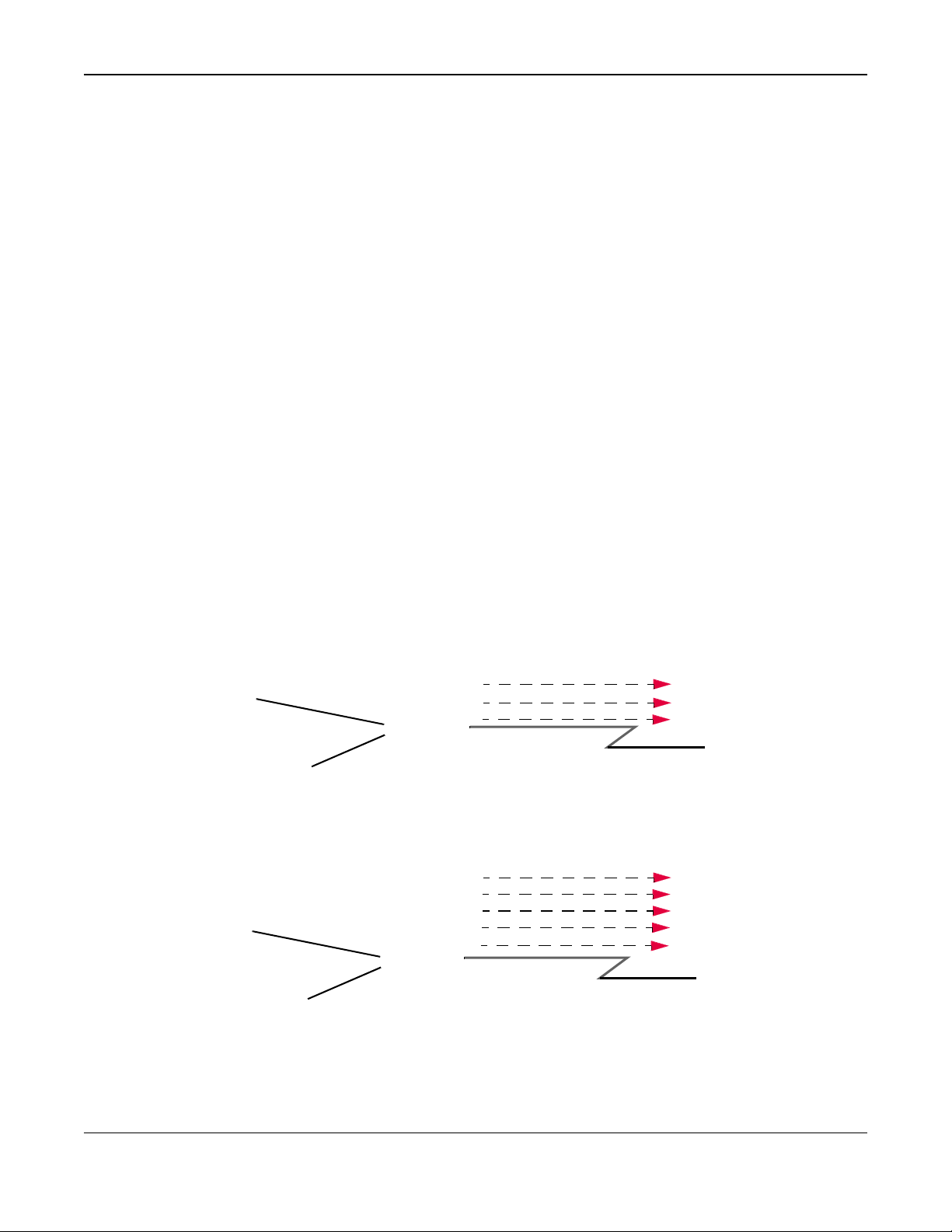
1.4.2 VMG’s USB Support
The USB port of the VMG is used for 3G WAN backup, file-sharing and media server.
3G WAN Backup
Connect a 3G/LTE USB dongle with an active SIM card to the USB port. This adds a second WAN
interface and a llows the VMG to wirele s sly access the Inte r net via a 3G/LTE network. The 3G/LTE
WAN connection is the f ailover or a backup in case the DSL or Ethernet WAN connection fails.
To set up a 3G/LTE connection, click Network Setting > Broadband > 3G Backup.
To update the supported 3G/LTE USB dongle lis t, download the late st WWAN package from the
ZyXEL website and upload it to the VMG using the Maintenance > Firmware Upgrade screen.
See the product page on ZyXEL’s website for the list of 3G/LTE US B don gles that are compatible.
Figure 3 VMG’s Internet Access Application: 3G WAN
WLAN
WAN
Ethernet WAN
3G/LTE
WAN
LAN
VMG1312-B10D User’s Guide
17
Page 18
Chapter 1 Introducing the VMG
File Sharing
Use the built-in USB 2.0 port to share files on a USB memory stick or a USB hard drive (B). You can
connect one USB hard drive to the VMG at a time. Use FTP to access the files on the USB device.
Figure 4 USB File Sharing Application
B
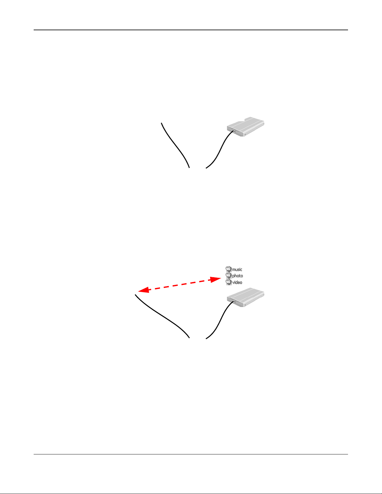
Media Server
You can also use the VMG as a media server. This lets anyone on your network play video, music,
and photos from a USB device (B) connected to the VMG’s USB port (without having to copy them
to another computer).
Figure 5 USB Media Server Application
A
1.5 Wireless Access
The VMG is a wireless Access Point (AP) for wireless clients, such as notebook computers or PDAs
and iPads. It allows them to connect to the Internet without having to rely on inconvenient Ethernet
cables.
A
VMG1312-B10D User’s Guide
18
B
Page 19

Chapter 1 Introducing the VMG
You can configure your wireless network in either the built-in Web Configurator, or using the WPS
button.
Figure 6 Wireless Access Example
1.5.1 Using the Wi-Fi and WPS Buttons
If the wireless netw or k is turned off, press the WLAN button for one second. Once the WLAN/
WPS LED turns green, the wireless network is active.
You can also use the WPS button to quickly set up a secure wireless connecti on between the VMG
and a WPS-compatible client by adding one dev i ce at a time.
To activate WPS:
1 Make sure the POWER LED is on and not blinking.
2 Press the WPS button for two seconds and release it.
3 Press the WPS button on another WPS-enabled device within range of the VMG. The WLAN/WPS
LED flashes orange while the VMG sets up a WPS connection with the other w ireless device.
4 Once the connection is successfully made, the WLAN/WPS LED shines green.
To turn off the wireless network, press the WLAN button for one to five seconds. The WLAN/WPS
LED turns off when the wireless network is off.
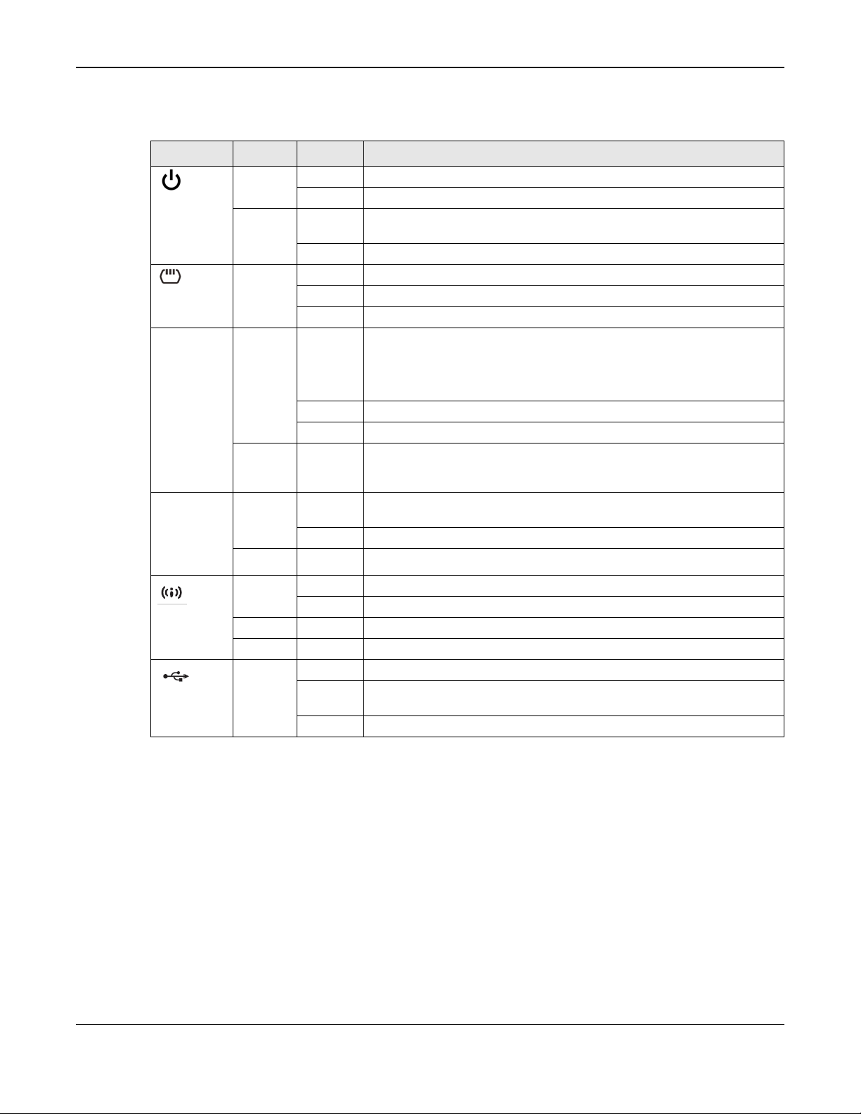
1.6 LEDs (Lights)
The following graphic displays the labels of the LEDs.
Figure 7 LEDs on the VMG
VMG1312-B10D User’s Guide
19
Page 20
Chapter 1 Introducing the VMG
On
None of the LEDs are on if the VMG is not receiving power.
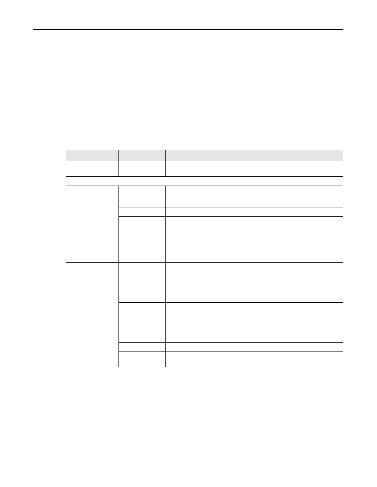
Table 1 LED Descriptions
LED
COLOR STATUS DESCRIPTION
Green
POWER
Red
Green
DSL
Green
On
Blinking The VMG is self-testing.
On
Off
On
Blinking The VMG is initializing the DSL line.
Off
On
The VMG is receiving power and ready for use.
The VMG detected an error while self-testing, or there is a device
malfunction.
The VMG is not receiving power.
The DSL line is up.
The DSL line is down.
The VMG has an IP connection but no traffic.
INTERNET
ETHERNET1
~4
WLAN/WPS
USB
Blinking The VMG is sending or receiving IP traffic.
Off
Red
Green
Green
Orange Blinking The VMG is setting up a WPS connection with a wireless client.
Green
On
Blinking The VMG is sending or receiving data to/from the LAN at 10/100 Mbps.
Off
On
Blinking The VMG is communicating with wireless clients.
Off
On
Blinking The VMG is sending/receiving data to/from the USB device connected to
Off
Your device has a WAN IP address (either static or assigned by a DHCP
server), PPP negotiation was successfully completed (if used) and the
DSL connection is up.
There is no Internet connection or the gateway is in bridged mode.
The VMG attempted to make an IP connection but failed. Possible
causes are no response from a DHCP server, no PPPoE response, PPPoE
authentication failed.
The VMG has a successful 10/100 Mbps Ethernet connection with a
device on the Local Area Network (LAN).
The VMG does not have an Ethernet connection with the LAN.
The wireless network is activated.
The wireless network is not activated.
The VMG recognizes a USB connection through the USB slot.
it.
The VMG does not detect a USB connection through the USB slot.
1.7 The RESET Button
If you forget your password or cannot access the Web Configurator, you will need to use the RESET
button at the back of the device to reload the factory-default configuration file. This means that you
will lose all configurations that you had previously and the password will be reset to “1234”.
1 Make sure the POWER LED is on (not blinking).
2 To set the device back to the factory default settings, press the RESET button for ten seconds or
until the POWER LED begin s to blink and then release it. When the POWER LED begins to blink,
the defaults have been r estored and the device restarts.
VMG1312-B10D User’s Guide
20
Page 21

2
2.1 Overview
The web configurator is an HTML-based management interface that allows easy VMG setup and
management via Internet browser. Use Internet Explorer 8.0 and later versions or Mozilla Firefox 3
and later versions or Safari 2.0 and later versions. The recommended screen resolution is 1024 by
768 pixels.
In order to use the web configurator you need to allow:
• Web browser pop-up windows from your VMG. Web pop-up blocking is enabled by default in
2.1.1 Accessing the Web Configurator
Windows XP SP (Service Pack) 2.
• JavaScript (enabled by default).
• Java permissions (enabled by default).
1 Make sure your VMG hardware is properly connected (refer to the Q uick Start Guide).
2 Launch your web browser. If the VMG does not automatically re-direct you to the login screen, go to
http://192.168.1.1.
3 A password screen displays. To access the administrative web configurator and manage the VMG,
type the default username admin and password 1234 in t he passwo rd scr een and click Login. If
you have changed the password, enter your password and click Login.
Figure 8 Password Screen
4 The following screen displays if you have not yet changed your password. Enter a new password,
retype it to confirm and click Apply.
The Web Configurator
VMG1312-B10D User’s Guide
21
Page 22

Chapter 2 The Web Configurator
Figure 9 Change Password Screen
5 The Quick Start Wizard screen appears. You can configure basic Internet access, and wireless
settings. See Chapter 3 on page 28 f or more information.
6 After you finished or closed the Quick Start Wizard screen, the Network Map page appears.
Figure 10 Network Map
7 Clickthe right arrow icon to display the Status screen, where you can view the VMG’s interface and
system information.
VMG1312-B10D User’s Guide
22
Page 23
Chapter 2 The Web Configurator
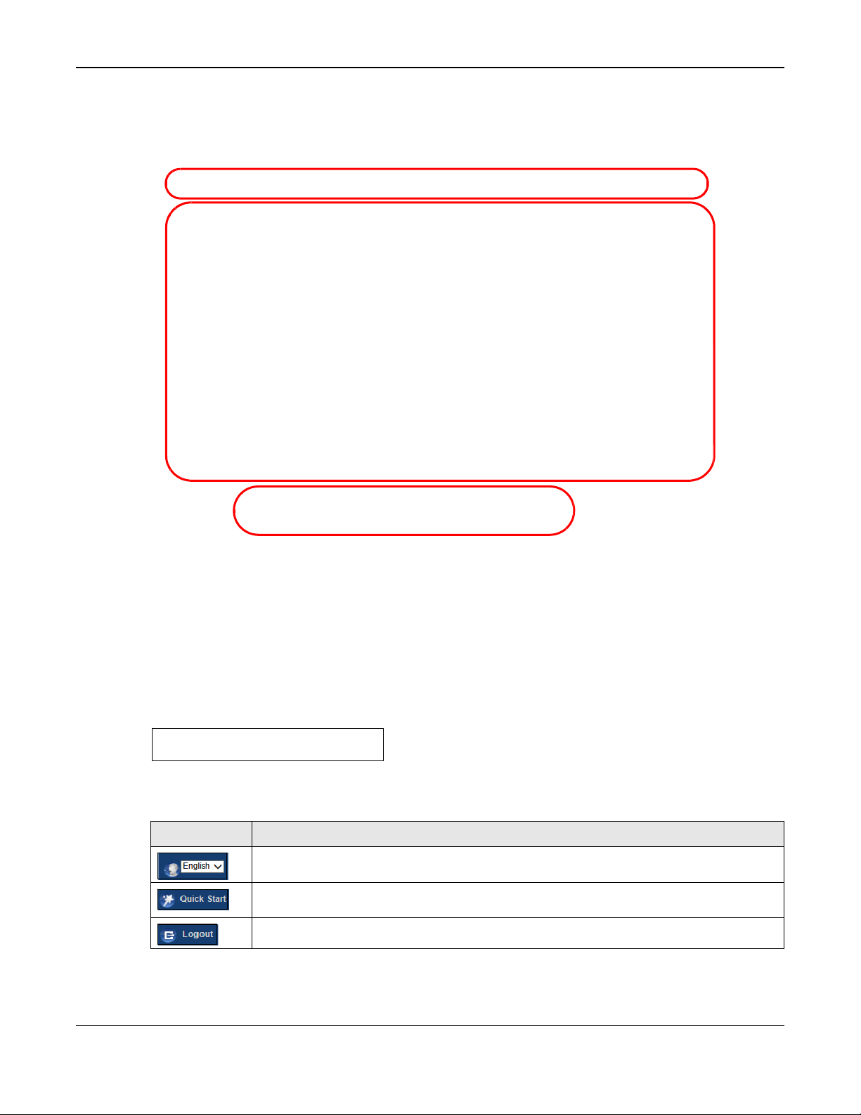
2.2 Web Configurator Layout
Figure 11 Screen Layout
A
B
As illustrated above, the main screen is divided into these parts:
• A - title bar
• B - main window
• C - navigation panel
2.2.1 Title Bar
The title bar provides some icons in the upper righ t corner.
The icons provide the follow ing functions.
Table 2 Web Configurator Ic on s in the Title Bar
ICON
C
DESCRIPTION
Language: Select the language you prefer.
Quick Start: Click this icon to open screens where you can configure the VMG’s time zone
Internet access, and wireless settings.
Logout: Click this icon to log out of the web configurator.
VMG1312-B10D User’s Guide
23
Page 24
Chapter 2 The Web Configurator
Network Setting
Broadband
Broadband
802.1x
Use this screen to view and configure the IEEE 802.1x settings on the
Wireless
General
Use this screen to configure the wireless LAN settings and WLAN
WPS
Use this screen to configure and view your WPS (Wi-Fi Protected
WMM
Use this screen to enable or disable Wi-Fi MultiMedia (WMM).
WDS
Use this screen to set up Wireless Distribution System (WDS) links to
Others
Use this screen to configure advanced wireless settings.
Channel Status
Use this screen to scan wireless LAN channel noises and view the
2.2.2 Main Window
The main window displays information and configuration fields. It is discussed in the res t of this
document.
After you click the right arrow icon on the Connection Status (Network Map) page, the Status
screen is displayed. See Chapter 5 on page 55 for more information a b out the Status screen.
2.2.3 Navigation Panel
Use the menu items on the navigation panel to open screens to configure VMG features. The
following tables describe each menu item.
Table 3 Navigation Panel Summary
LINK
Connection Status
TAB
3G Backup
Advanced
Ethernet WAN Use this screen to convert Ethernet LAN 4 port as WAN port, or
FUNCTION
This screen shows the network status of the VMG and computers/
devices connected to it.
Use this screen to view and configure ISP parameters, WAN IP
address assignment, and other advanced properties. You can also add
new WAN connections.
Use this screen to configure 3G/LTE WAN connection.
Use this screen to enable or disable PTM over ADSL, Annex M/Annex
J, and DSL PhyR functions.
restore the WAN port to LAN port.
VMG.
authentication/security settings.
Guest/More AP Use this screen to configure multiple BSSs on the VMG.
MAC
Authentication
Use this screen to block or allow wireless traffic from wireless devices
of certain SSIDs and MAC addresses to the VMG.
Setup) settings.
other access points.
results.
VMG1312-B10D User’s Guide
24
Page 25

Chapter 2 The Web Configurator
STB Vendor ID
Routing
Static Route
Use this screen to view and set up static routes on the VMG.
DNS Route
Shaper Setup
Use this screen to limit outgoing traffic rate on the selected interface.
Policer Setup
NAT
Port Forwarding
Applications
Use this screen to configure servers behind the VMG.
Port Triggering
Use this screen to change your VMG’s port triggering settings.
DMZ
Use this screen to configure a default server which receives packets
DNS
DNS Entry
Use this screen to view and configure DNS routes.
Dynamic DNS
Use this screen to allow a static hostname alias for a dynamic IP
IGMP/MLD
IGMP/MLD
Use this screen to configure multicast settings (IGMP for IPv4 and
Vlan Group
Vlan Group
Use this screen to group and tag VLAN IDs to outgoing traffic from
Interface
Interface
Use this screen to map a port to a PVC or bridge group.
USB Service
File Sharing
Use this screen to enable file sharing via the VMG.
Media Server
Use this screen to use the VMG as a med ia server.
Table 3 Navigation Panel Summary (continued)
LINK
Home
Networking
QoS
TAB
LAN Setup
Static DHCP
UPnP
Additional
Subnet
Wake on LAN
TFTP Server
Name
Policy Route
RIP
General
Queue Setup
Classification
Setup
FUNCTION
Use this screen to configure LAN TCP/IP settings, and other advanced
properties.
Use this screen to assign specific IP addresses to individual MAC
addresses.
Use this screen to turn UPnP and UPnP NAT-T on or off.
Use this screen to configure IP alias and public static IP.
Use this screen to configure the Vendor IDs of the connected Set Top
Box (STB) devices, which have the VMG automatically create static
DHCP entries for the STB devices when they request IP addresses.
Use this screen to remotely turn on a device on the local network.
Configure a TFTP server name which is sent to clients using DHCP
option 66.
Use this screen to forward DNS queries for certain domain names
through a specific WAN interface to its DNS server(s).
Use this screen to configure policy routing on the VMG.
Use this screen to configure Routing Information Protocol to
exchange routing information with other routers.
Use this screen to enable QoS and traffic prioritizing. You can also
configure the QoS rules and actions.
Use this screen to configure QoS queues.
Use this screen to define a classifier.
ALG
Address Mapping Use this screen to change your VMG’s address mapping settings.
Sessions
Grouping
Grouping
VMG1312-B10D User’s Guide
Use this screen to make your local servers visible to the outside
world.
from ports that are not specified in the Port Forwarding screen.
Use this screen to enable or disable SIP ALG.
Use this screen to configure the maximum number of NAT sessions
each client host is allowed to have through the VMG.
address.
MLD for IPv6 multicast groups) on the WAN.
the specified interface.
25
Page 26

Chapter 2 The Web Configurator
Parental
Parental Control
Use this screen to block web sites with the specific URL.
Certificates
Local
Certificates
LAN
NAT
Use this screen to view NAT statistics for connected hosts.
ARP table
ARP table
Use this screen to view the ARP table. It displays the IP and MAC
Multicast
Table 3 Navigation Panel Summary (continued)
LINK
Security
Firewall
MAC Filter
Control
Scheduler Rule Scheduler Rule Use this screen to configure the days and times when a configured
System Monitor
Log
TAB
General
Protocol
Access Control
DoS
MAC Filter
Trusted CA
System Log
Security Log
FUNCTION
Use this screen to configure the security level of your firewall.
Use this screen to add Internet services and configure firewall rules.
Use this screen to enable specific traffic directions for network
services.
Use this screen to activate protection against Denial of Service (DoS)
attacks.
Use this screen to block or allow traffic from devices of certain MAC
addresses to the VMG.
restriction (such as parental control) is enforced.
Use this screen to view a summary list of certificates and manage
certificates and certification requests.
Use this screen to view and manage the list of the trusted CAs.
Use this screen to view the status of events that occurred to the VMG.
You can export or e-mail the logs.
Use this screen to view all security related events. You can select
level and category of the security events in their proper drop-down
list window.
Levels include:
• Emergency
• Alert
• Critical
• Error
• Warning
• Notice
• Informational
• Debugging
Categories include:
Traffic Status WAN
Routing Table Routing Table
Status
xDSL Statistics xDSL Statistics Use this screen to view the VMG’s xDSL traffic statistics.
IGMP Status
MLD Status
VMG1312-B10D User’s Guide
• Account
• Attack
• Firewall
• MAC Filter
Use this screen to view the status of all network traffic going through
the WAN port of the VMG.
Use this screen to view the status of all network traffic going through
the LAN ports of the VMG.
address of each DHCP connection.
Use this screen to view the routing table on the VMG.
Use this screen to view the status of all IGMP settings on the VMG.
Use this screen to view the status of all MLD settings on the VMG.
26
Page 27

Chapter 2 The Web Configurator
3G Statistics
3G Statistics
Use this screen to look at 3G Internet connection status.
Maintenance
System
System
Table 3 Navigation Panel Summary (continued)
LINK
User Account User Account
Remote
Management
SNMP
Time
Email
Notification
Log Setting
Firmware
Upgrade
Backup
Reboot
Diagnostic
Restore Backup/Restore Use this screen to backup and restore your VMG’s configuration
TAB
MGMT Services Use this screen to enable specific traffic directions for network
Trust Domain
SNMP
Time
Email
Notification
Log Setting
Firmware
Upgrade
Reboot
Ping&Traceroute
&Nslookup
802.1ag
OAM Ping
FUNCTION
Use this screen to set Device name and Domain name.
Use this screen to change user password on the VMG.
services.
Use this screen to configure a list of public IP addresses which are
allowed to access the VMG.
Use this screen to configure SNMP (Simple Network Management
Protocol) settings.
Use this screen to change your VMG’s time and date.
Use this screen to configure up to two mail servers and sender
addresses on the VMG.
Use this screen to change your VMG’s log settings.
Use this screen to upload firmware to your VMG.
(settings) or reset the factory default settings.
Use this screen to reboot the VMG without turning the power off.
Use this screen to identify problems with the DSL connection. You can
use Ping, TraceRoute, or Nslookup to help you identify problems.
Use this screen to configure CFM (Connectivity Fault Management)
MD (maintenance domain) and MA (maintenance association),
perform connectivity tests and view test reports.
Use this screen to view information to help you identify problems with
the DSL connection.
VMG1312-B10D User’s Guide
27
Page 28

3
3.1 Overview
Use the Quick Start screens to configure the VMG’s time zone, basic Internet access, and wireless
settings.
Note: See the technical reference chapters (starting on Chapter 4 on page 31) for
background information on the features in this chapter.
3.2 Quick Start Setup
1 The Quick Start Wizard appears automatically after login. Or you can click the Quick Start icon in
the top right corner of the web configurator to open the quick start screens. Select the time zone of
your location. Click Next.
Figure 12 Quick Start - Welcome
2 Enter your Internet connection information in this screen. The screen and fields to enter may vary
depending on your current conn ection type. Click Next.
Quick Start
VMG1312-B10D User’s Guide
28
Page 29

Chapter 3 Quick Start
Figure 13 Quick Start - Internet Connection
3 Turn the wireless LAN on or off. If you keep it on, record the security settings so you can configure
your wireless clients to connect to the VMG. Click Save.
Figure 14 Quick Start - Wireless Setting
4 Your VMG saves your settings and attempts to connect to the Internet. Click Close to complete the
setup.
VMG1312-B10D User’s Guide
29
Page 30

Chapter 3 Quick Start
Figure 15 Quick Start - Result Summary
VMG1312-B10D User’s Guide
30
Page 31

4
4.1 Overview
This chapter shows you how to use the VMG’s various features.
• Setting Up an ADSL PPPoE Connection, see page 31
• Setting Up a Secure Wireless Network, see page 34
• Setting Up Multip le Wireless Groups, see page 40
• Configuring Sta tic Route for Routing to Another Network, see page 43
• Configuring QoS Queue and Class Setup, see page 45
• Access the VMG Using DDNS, see page 49
• Configuring the MAC Address F ilter, see page 50
• Access Your Shared Files From a Computer, see page 51
4.2 Setting Up an ADSL PPPoE Connection
This tutorial shows you how to set up an ADSL Internet connection using the Web Configurator.
If you connect to the Internet through an ADSL connection, use the information from your Internet
Service Provider (ISP) to configure the VM G . Be sure to contact your service provider for any
information you need to configure the Broadband screens.
1 Click Network Setting > Broad ba nd to open the following screen. Click Add New WAN
Interface.
2 In this example, the DSL connection has the followin g information.
Tutorials
VMG1312-B10D User’s Guide
31
Page 32

Chapter 4 Tutorials
General
Name
Type
Connection Mode
Encapsulation
IPv6/IPv4 Mode
ATM PVC Configuration
VPI/VCI
Encapsulation Mode
Service Category
Account Information
PPP User Name
PPP Password
PPPoE Service Name
Static IP Address
Others
MyDSLConnection
ADSL
Routing
PPPoE
IPv4
36/48
LLC/SNAP-Bridging
UBR without PCR
1234@DSL-Ex.com
ABCDEF!
MyDSL
192.168.1.32
Authentication Method: AUTO
PPPoE Passthrough: Disabled
NAT: Enabled
IGMP Multicast Proxy: Enabled
Apply as Default Gateway: Enabled
VLAN: Disabled
3 Select the Active check box. Enter the General and ATM PVC Configuration settings as provided
above.
Set the Type to ADSL over ATM.
Choose the Encapsulation specified by your DSL service provider. For this example, the service
provider requires a username and password to establish Internet connection. Therefor e, select
PPPoE as the WAN encapsulation type.
Set the IPv6/IPv4 Mode to IPv4 Only.
4 Enter the account information provided to you by your DSL serv ic e pr ovider.
5 Configure this rule as your default Internet connection by selecting the Apply as Default Gateway
check box. Then select DNS as Static and enter the DNS server addresses provided to you, such as
192.168.5.2 (DNS server1)/192.168.5.1 (DNS server2).
6 Leave the rest of th e fields to the default settings.
7 Click Apply to save your settings.
VMG1312-B10D User’s Guide
32
Page 33

Chapter 4 Tutorials
8 You should see a summary of your new DSL connection setup in the Broadband screen as follows.
Try to connect to a website to see if you have correctly set up your Internet connection. Be sure to
contact your service provider for any information you need to configure the WAN screens.
VMG1312-B10D User’s Guide
33
Page 34

Chapter 4 Tutorials
SSID
Example
Security Mode
WPA2-PSK
Pre-Shared Key
DoNotStealMyWirelessNetwork
802.11 Mode
802.11b/g/n Mixed
4.3 Setting Up a Secure Wireless Network
Thomas wants to set up a wireless network so that he can use his notebook to access the Internet.
In this wireless network, the VMG serves as an access point (AP), and the notebook is the wireless
client. The wireless client can access the Internet through the AP.
Thomas has to configure the wireless network settings on the VMG. T hen he c an set up a wireless
network using WPS (Section 4.3.2 on page 36) or manual configuration (Section 4.3.3 on page 39).
4.3.1 Configuring the Wireless Network Settings
This example uses the following parameters to set up a wireless network.
1 Click Network Setting > Wireless to open the General screen. Select More Secure as the
security level and WPA2-PSK as the security mode. Configure the screen using the provided
parameters (see page 34). Click Apply.
VMG1312-B10D User’s Guide
34
Page 35

Chapter 4 Tutorials
2 Go to the Wireless > Others screen and select 802.11b/g/n Mixed in the 802.11 Mode field.
Click Apply.
VMG1312-B10D User’s Guide
35
Page 36

Chapter 4 Tutorials
Thomas can now use the WPS feature to establish a wireless connection between his notebook and
the VMG (see Section 4.3.2 on page 36). He can also use the notebook’s wireless client to search
for the VMG (see Section 4.3.3 on page 39).
4.3.2 Using WPS
This section shows you how to set up a wireless network using WPS. It uses the VMG as the AP and
ZyXEL NWD210N as the wireless client which connects to the notebook.
Note: The wireless client must be a WPS-aware device (for example, a WPS USB adapter
or PCMCIA card).
There are two WPS meth ods to set up the wireless client settings:
• Push Button Configuration (P BC ) - simply press a button. This is the easier of the two
methods.
• PIN Configuration - configur e a Personal Identification Number (PIN) on the VMG. A wireless
client must also use the same PIN in order to download the wireless network settings from the
VMG.
Push Button Configuration (PBC)
1 Make sure that your VMG is turned on and your notebook is within the cover range of the wireless
signal.
2 Make sure that you have installed the wireless client driver and utility in your notebook.
3 In the wireless client utility, go to the WPS setting page. Enable WPS and press the WPS button
(Start or WPS button).
4 Push and hold the WPS button located on the VMG’s front pane l for more than 5 seconds.
Alternatively, you may log into VMG’s web configurator and go to the Network Setting >
Wireless > WPS screen. Enable the WPS function for method 1 and click Apply. Then click the
WPS button.
1
3
2
VMG1312-B10D User’s Guide
36
Page 37

Chapter 4 Tutorials
Note: Your VMG has a WPS button located on the side of the device as well as a WPS
button in its configuration utility. Both buttons have exactly the same function: you
can use one or the other.
Note: It doesn’t matter which button is pressed first. You must press the second button
within two minutes of pressing the first one.
The VMG sends the proper configuration settings to the wireless client. This may take up to two
minutes. The wireless client is then able to communicate with the VMG securely.
The following figure shows you an example of how to set up a wireless network and its security by
pressing a button on both VMG and wireless client.
Wireless Client
VMG
PIN Configuration
When you use the PIN configuration method, you need to use both the VMG’s web configurator and
the wireless client’s utility.
1 Launch your wireless client’s configuration utility. Go to the WPS settings and select the PIN method
to get a PIN number.
SECURITY INFO
COMMUNICATION
WITHIN 2 MINUTES
Press and hold for
5 seconds
WPS
2 Log into VMG’s web configurator an d g o to the Network Setting > Wireless > WPS screen.
Enable the WPS function and click Apply.
VMG1312-B10D User’s Guide
37
Page 38

Chapter 4 Tutorials
3 Enter the PIN number of the wireless client and click the Register button. Activate WPS function on
the wireless client utility screen within two minutes.
The VMG authenticates the wireless client and sends the proper configuration settings to the
wireless client. This may take up to two minutes. The wireless client is then able to com m unicate
with the VMG securely.
The following figure shows you how to set up a wireless network and its security on a VMG and a
wireless client by using PIN method.
3
1
2
VMG1312-B10D User’s Guide
38
Page 39
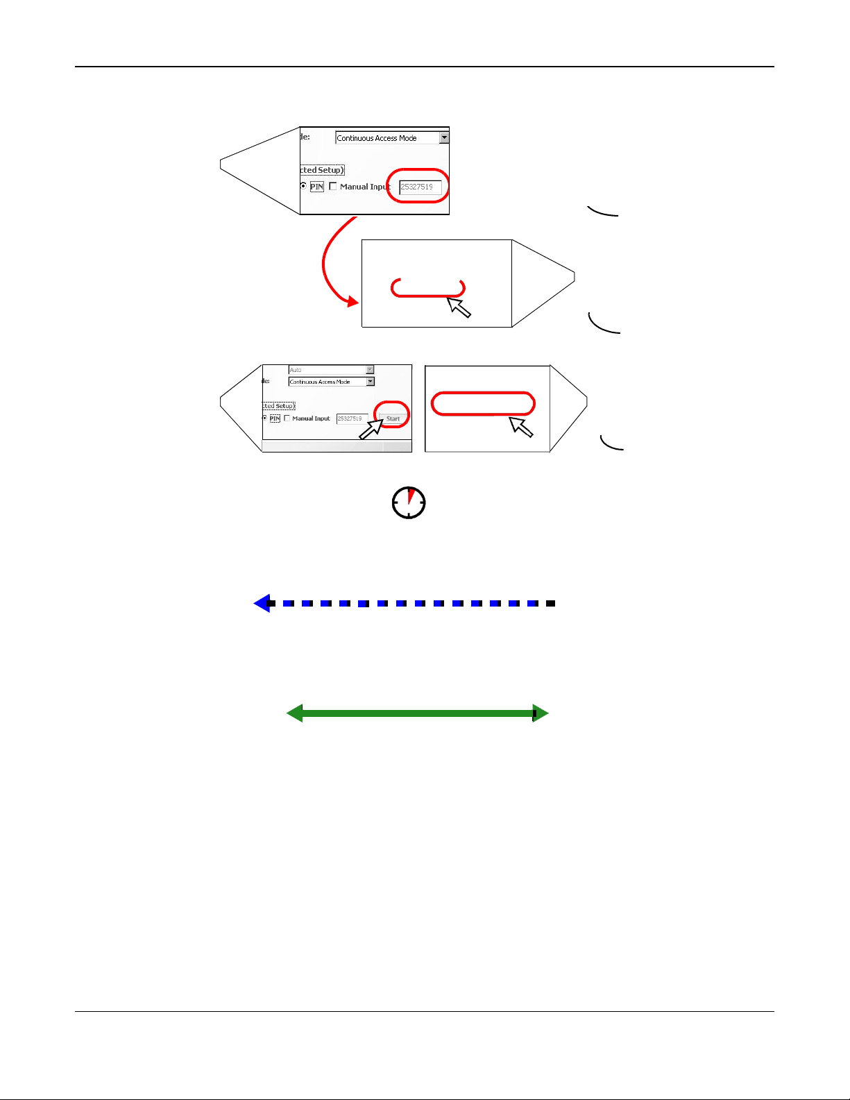
Chapter 4 Tutorials
Wireless Client
WITHIN 2 MINUTES
Authentication by
PIN
VMG
4.3.3 Without WPS
Use the wireless adapter’s utility installed on the notebook to search for the “Example” SSID. Then
enter the “DoNotStealMyWirelessNetwork” pre-shared key to establish an wirel es s Internet
connection.
Note: The VMG supports IEEE 802.11b and IEEE 802.11g wireless clients. Make sure that
your notebook or computer’s wireless adapter supports one of these standards.
SECURITY INFO
COMMUNICATION
VMG1312-B10D User’s Guide
39
Page 40
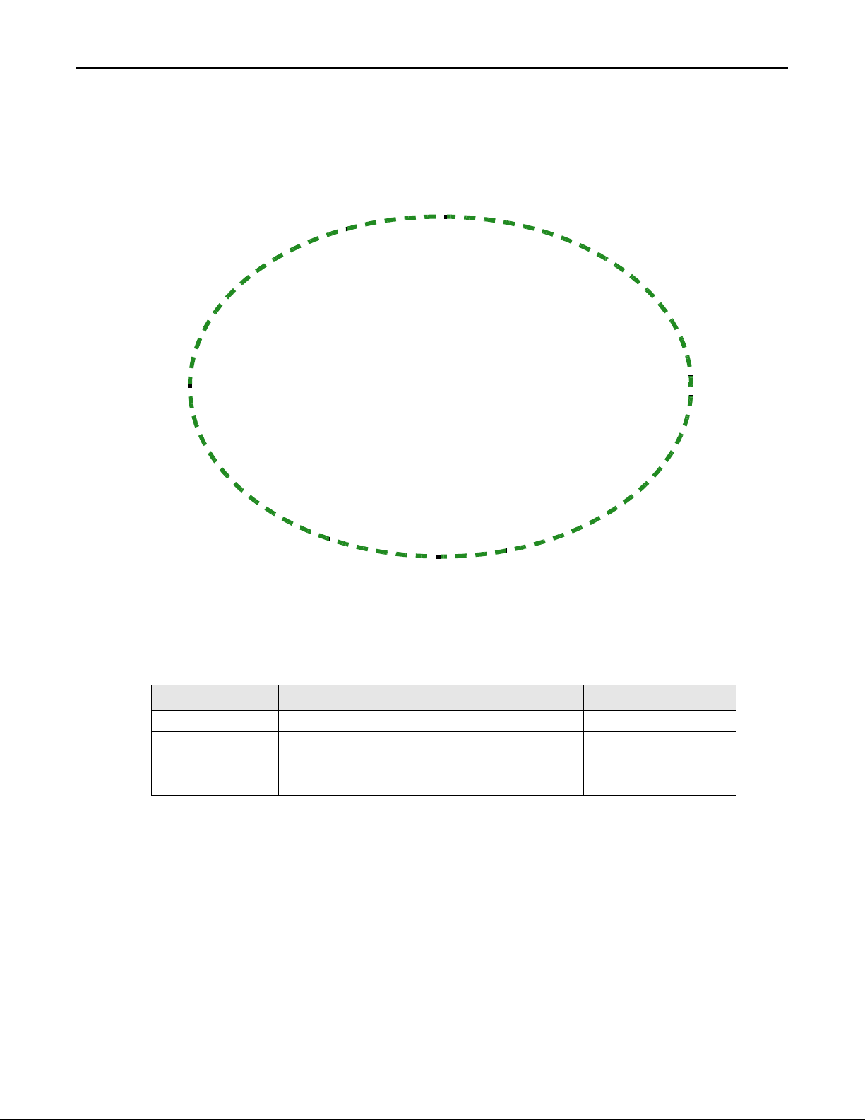
Chapter 4 Tutorials
4.4 Setting Up Multiple Wireless Groups
Company A wants to create different wireless network groups for different types of users as shown
in the following f igu r e. Each group has its own SSID and security mode.
Company
VIP
• Employees in Company A will use a general Company wireless network group.
• Higher management level and important visitors will use the VIP group.
• Visiting guests w ill use the Guest group, which has a different SSID and password.
Company A will use the following parameters to set up the wireless network groups.
COMPANY
SSID
Security Level
Security Mode
Pre-Shared Key
1 Click Network Setting > Wireless to open the General screen. Use this screen to set up the
company’s general wireless network group. Configure the screen using the provided parameters
and click Apply.
Company
More Secure
WPA2-PSK
ForCompanyOnly
VIP
VIP
More Secure
WPA2-PSK
123456789
Guest
GUEST
Guest
More Secure
WPA2-PSK
guest123
VMG1312-B10D User’s Guide
40
Page 41

Chapter 4 Tutorials
2 Click Network Setting > Wireless > Guest/More AP to open the following screen. Click the
Edit icon to configure the s econd wireless network group.
3 Configure the screen using the provided parameters and click Apply.
VMG1312-B10D User’s Guide
41
Page 42

Chapter 4 Tutorials
4 In the Guest/More AP screen, click the Edit icon to configure the third wireless network
group.Configure the screen using the provided parameters and click Apply.
VMG1312-B10D User’s Guide
42
Page 43

Chapter 4 Tutorials
5 Check the status of VIP and Guest in the Guest/More AP screen. The yellow bulbs signify that the
SSIDs are active and ready for wireless access.
4.5 Configuring Static Route for Routing to Another
Network
In order to extend your Intranet and control traffic flowing directions, you may connect a router to
the VMG’s LAN. The router may be used to separate two department networks. This tutorial shows
how to configure a static routing rule for two network routings.
VMG1312-B10D User’s Guide
43
Page 44

Chapter 4 Tutorials
A
In the following figure, router R is connected to t he VMG ’s LAN. R connects to two networks, N1
(192.168.1.x/24) and N2 (192.168.10.x/24). If you want to send traffic from computer A (in N1
network) to computer B (in N2 network), the traffic is sent to the VMG’s WAN default gateway by
default. In this case, B will never receive the traffic.
N1
A
R
N2
B
You need to specify a static routing rule on the VMG to specify R as the router in charge of
forwarding traffic to N2. In this case, the VMG routes traffic from A to R and then R routes the
traffic to B.
N1
A
R
N2
B
This tutorial uses the fol lowing example IP settings:
Table 4 IP Settings in this Tutorial
DEVICE / COMPUTER
The VMG’s WAN
The VMG’s LAN
IP Type
Use Interface
IP ADDRESS
172.16.1.1
192.168.1.1
IPv4
VDSL/ppp1.1
192.168.1.34
VMG1312-B10D User’s Guide
44
Page 45
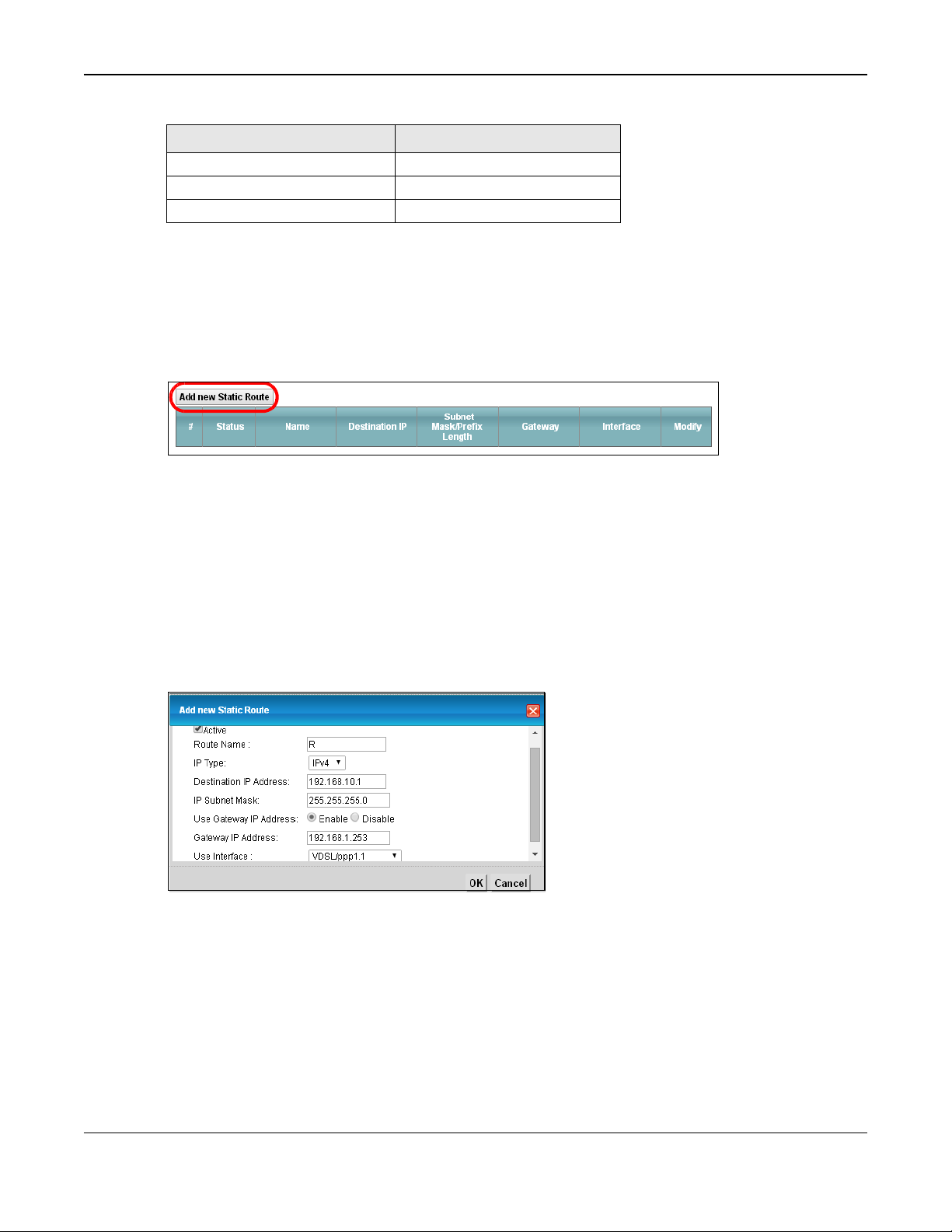
Chapter 4 Tutorials
R
R
B
Table 4 IP Settings in this Tutorial
DEVICE / COMPUTER
’s N1
’s N2
To configure a static route to route traffic from N1 to N2:
IP ADDRESS
192.168.1.253
192.168.10.2
192.168.10.33
1 Log into the VMG’s Web Configurator in advanced mode.
2 Click Network Setting > Routing.
3 Click Add new Static Route in the Static Route screen.
4 Configure the Static Route Setup screen using the following settings:
4a Select the Active check box. Enter the Route Name as R.
4b Set IP Ty pe to IPv4.
4c Type 192.168.10.0 and subnet mask 255.255.255.0 for the destination, N2.
4d Select Enable in the Use Gateway IP Address field. Type 192.168.1.253 (R’s N1 address)
in the Gateway IP Address field.
4e Select VDSL/ppp1.1 as the Use Interface.
4f Click OK.
Now B should be able to receive traffic from A. You may need to additionally configure B’s firewall
settings to allow specific traffic to pass through.
4.6 Configuring QoS Queue and Class Setup
This section contains tutorials on how you can configure the QoS screen.
VMG1312-B10D User’s Guide
45
Page 46
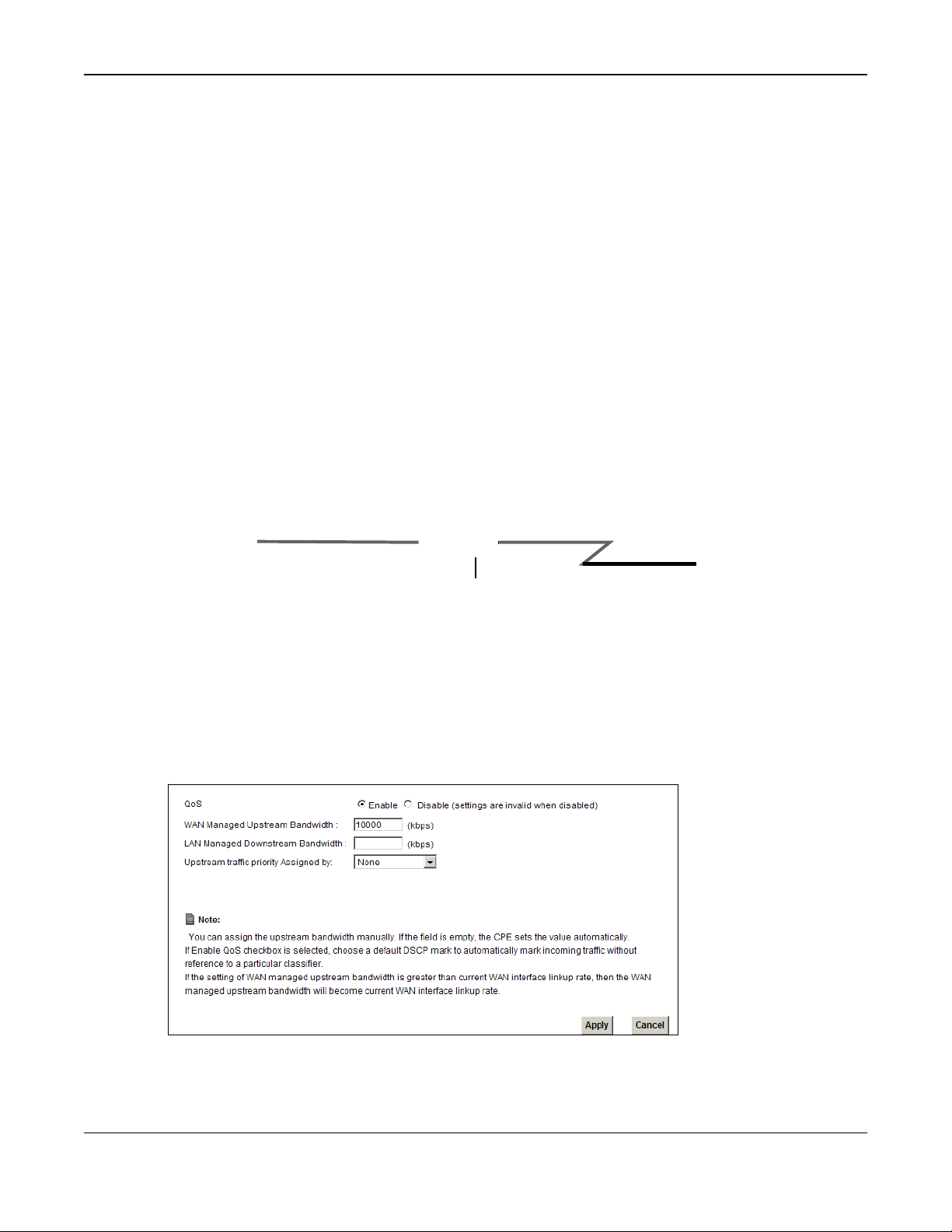
Chapter 4 Tutorials
Let’s say you are a team leader of a small sales branch office. You want to prioritize e-mail traffic
because your task includes sending urgent updates to clients at least twice every hour. You also
upload data files (such as logs and e-mail archives) to the FTP server throughout the day. Your
colleagues use the Internet for research, as well as chat applications for communicating with other
branch offices.
In the following figure, your Internet connection has an upstream transmission bandwidth of
10,000 kbps. For this ex amp le, you want to configure QoS so that e-mail traffic gets the highest
priority with at lea st 5,000 kbps. You can do the following:
• Configure a queue to assign the highest priority queue (1) to e-mail traffic going to the WAN
interface, so th a t e -mail traffic would not get delayed when there is network congestion.
• Note the IP address (192.168.1.23 for example) and/or MAC address (AA:FF:AA:FF:AA:FF for
example) of your com puter and map it to queue 7.
Note: QoS is applied to traffic flowing out of the VMG.
Traffic that does not match th is class is assigned a priority queue based on the internal QoS
mapping table on the VMG.
DSL
10,000 kbps
Your computer
IP=192.168.1.23
and/or
MAC=AA:FF:AA:FF:AA:FF
Email traffic: Highest priority
1 Click Network Setting > QoS > General and select Enable. Set your WAN Managed Upstream
Bandwidth to 10,000 kbps (or leave this blank to have th e V MG automatically determine this
figure). Click Apply.
2 Click Queue Setup > Add new Queue to create a new queue. In the screen that opens, check
Active and enter or select the following values:
• Name: E-mail
A colleague’s computer
Other traffic: Automatic classifier
VMG1312-B10D User’s Guide
46
Page 47

Chapter 4 Tutorials
• Interface: WAN
• Priority: 1 (High)
• Weight: 8
• Rate Limit: 5,000 (kbps)
3 Click Class Setup > Add new Clas sifier to create a new class. Check Active and follow the
settings as shown in the screen below.
VMG1312-B10D User’s Guide
47
Page 48

Chapter 4 Tutorials
Class Name
From
Interface
Ether Type
IP Address
MAC Address Type the MAC address of your computer - AA:FF:AA:FF:AA:FF. Type the MAC Mask if you
To Queue
Index
Give a class name to this traffic, such as E-mail in this example.
This is the interface from which the traffic will be coming from. Select LAN1 for this
example.
Select IP to identify the traffic source by its IP address or MAC address.
Type the IP address of your computer - 192.168.1.23. Type the IP Subnet Mask if you
know it.
know it.
Link this to an item in the Network Setting > QoS > Queue Setup screen, which is the E-
mail queue created in this example.
VMG1312-B10D User’s Guide
48
Page 49

Chapter 4 Tutorials
This maps e-mail traffic coming from port 25 to the highest priority, which you have created in the
previous screen (see the IP Protocol field). This also maps your computer’s IP address and MAC
address to the E-mail queue (see the Source fields).
4 Verify that the queue setup works by checking Network Setting > QoS > Monitor. This shows
the bandwidth allotted to e-mail traffic compared to othe r network traffic.
4.7 Access the VMG Using DDNS
If you connect your VMG to the Internet and it uses a dynamic WAN IP address, it is inconvenient
for you to manage the device from the Internet. The VMG’s WAN IP address changes dynamically.
Dynamic DNS (DDNS) allows you to access the VMG using a domain name.
w.x.y.z
To use this feature, you have to apply for DDNS service at, for example, www.dyndns.org.
http://zyxelrouter.dyndns.org
A
a.b.c.d
This tutorial covers:
• Registering a DDNS Account on www.dyndns.org
• Configuring DDNS on Your VMG
• Testing the DDNS Setting
Note: If you have a private WAN IP address, then you cannot use DDNS.
4.7.1 Registering a DDNS Account on
1 Open a browser and type http://www.dyndns.org.
2 Apply for a user account. This tutorial u s es UserName1 and 12345 as the username and
password.
3 Log into www.dyndns.org using your account.
4 Add a new DDNS host name. This tutorial uses the following settings as an example.
• Hostname: zyxelrouter.dyndns.org
• Service Type: Host with IP address
• IP Address: Enter the WAN IP address that your VMG is currently using. You can find the IP
address on the VMG’s Web Configurator Status page.
Then you will need to conf igure the same account and host name on the VMG later.
www.dyndns
.org
VMG1312-B10D User’s Guide
49
Page 50

Chapter 4 Tutorials
4.7.2 Configuring DDNS on Your VMG
Configure the f ollowing settings in the Network Setting > DNS > Dynamic DNS screen.
• Select Enable Dynamic DNS.
• Select www.DynDNS.com as the service provider.
• Type zyxelrouter.dyndns.org in the Host Name field.
• Enter the user name (UserName1) and password (12345).
Click Apply.
4.7.3 Testing the DDNS Setting
Now you should be able to access the VMG from the Internet. To test this:
1 Open a web browser on the computer (using the IP address a.b.c.d) that is connected to the
Internet.
2 Type http://zyxelrouter.dyndns.org and press [Enter].
3 The VMG’s login page should appear. You can then log into the VMG and manage it.
4.8 Configuring the MAC Address Filter
Thomas noticed that his daughter Joseph ine spends too much time surfing the web a nd
downloading media files. He decided to prevent Josephine from accessing the Internet so that she
can concentrate on preparing f or her final exams.
Josephine’s computer connects wirelessly to the Internet through the VMG. Thomas decides to use
the Security > MAC Filter screen to grant wireless network access to his computer but not to
Josephine’s computer.
VMG1312-B10D User’s Guide
50
Page 51
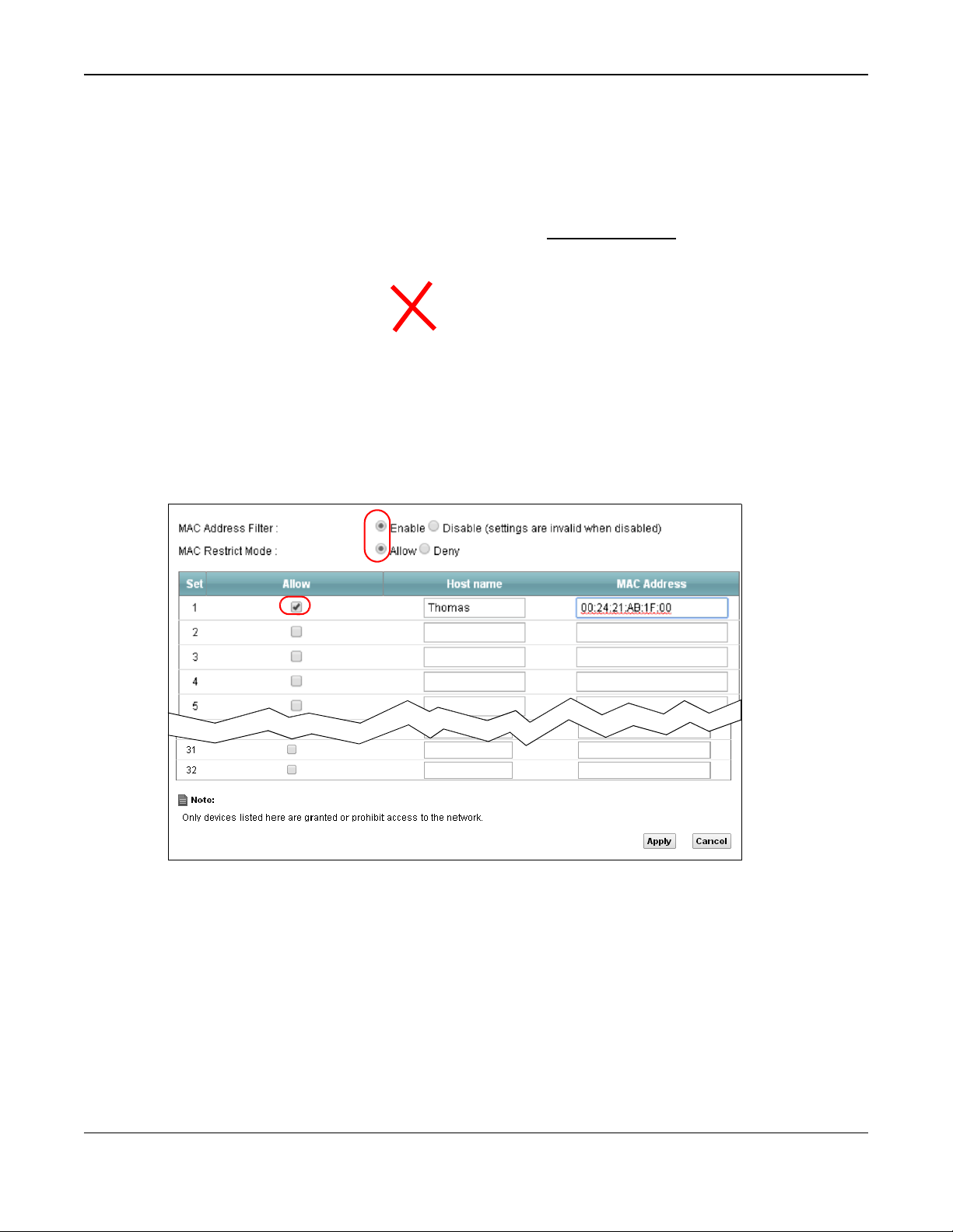
Chapter 4 Tutorials
Thomas
1 Click Security > MAC Filter to open the MAC Filter screen. Select the Enable check box to
activate MAC filter function.
2 Select Allow. Then enter the host name and MAC address of Thomas’ computer in this screen. Click
Apply.
Thomas can also grant access to the computers of other members of his family and friends.
However, Josephine and others not listed in this screen will no longer be able to access the Internet
through the VMG.
Josephine
4.9 Access Your Shared Files From a Computer
Here is how to use an FTP program to access a file storage device connected to the VMG’s USB port.
Note: This example uses the FileZilla FTP program to browse your shared files.
VMG1312-B10D User’s Guide
51
Page 52

Chapter 4 Tutorials
1 In FileZilla enter the IP address of the VMG (the default is 192.168.1.1), your account’s user name
and password and port 21 and click Quickconnect. A screen asking for password authentication
appears.
2 Once you log in the USB device displays in the mnt folder.
VMG1312-B10D User’s Guide
52
Page 53

PART II
Technical Reference
53
Page 54

5
Network Map and Status Screens
5.1 Overview
After you log into the Web Configurator, the Network Map screen appears. This shows the network
connection status of the VMG and clients connected to it.
You can use the Status screen to look at the current status of the VMG, system resources, and
interfaces (LAN, WAN, and WLAN).
5.2 The Network Map S cr een
Use this screen to view the netw or k connection status of the devic e a nd its clients. A warning
message appears if there is a connection problem.
Figure 16 Network Map: Icon View Mode
VMG1312-B10D User’s Guide
54
Page 55
Chapter 5 Network Map and Status Screens
If you want to view information about a client, click the client’s name and Info. Click the IP address
if you want to change it. If you want to change the name or icon of the client, click Change icon/
name.
If you prefer to view the status in a lis t, click List View in the Viewing mode selection box. You
can configure how often you want the VMG to update this screen in Refresh interval.
Figure 17 Network Ma p: List View Mode
5.3 The Status Screen
Use this screen to view the statu s of the VMG. Click the r ig ht arrow icon in the Network Map
(Connection Status) screen to open this screen.
VMG1312-B10D User’s Guide
55
Page 56

Chapter 5 Network Map and Status Screens
Figure 18 Status Screen
Each field is described in the follow ing table.
Table 5 Status Screen
LABEL
Refresh Interval
Device Information
Host Name
Model Number This shows the model number of your VMG.
Serial Number This shows the serial number of your VMG.
Firmware
Version
WAN Information (These fields display when you have a WAN connection.)
Encapsulation This field displays the current encapsulation method.
IP Address
IP Subnet Mask This field displays the current subnet mask in the WAN.
DESCRIPTION
Select how often you want the VMG to update this screen.
This field displays the VMG system name. It is used for identification.
This is the current version of the firmware inside the VMG.
This field displays the current IP address of the VMG in the WAN. Click Release to
release your IP address to 0.0.0.0. If you want to renew your IP address, click Renew.
VMG1312-B10D User’s Guide
56
Page 57

Chapter 5 Network Map and Status Screens
System Up
Table 5 Status Screen (continued)
LABEL
MAC Address
Primary/
Secondary DNS
Server
DHCP
LAN Information
IP Address
IP Subnet Mask This is the current subnet mask in the LAN.
IPv6 Link Local
Address
DHCP
DESCRIPTION
This field displays the WAN Ethernet adapter MAC (Media Access Control) Address of
your VMG.
This field displays the first/second DNS server IP address assigned to the VMG.
This field displays whether the WAN interface is using a DHCP IP address or a static IP
address. Choices are:
Client - The WAN interface can obtain an IP address from a DHCP server.
None - The WAN interface is using a static IP address.
This is the current IP address of the VMG in the LAN.
This is the current IPv6 link local address of the VMG in the LAN.
This field displays what DHCP services the VMG is providing to the LAN. The possible
values are:
Server - The VMG is a DHCP server in the LAN. It assigns IP addresses to other
computers in the LAN.
Relay - The VMG acts as a surrogate DHCP server and relays DHCP requests and
responses between the remote server and the clients.
Disable - The VMG is not providing any DHCP services to the LAN.
MAC Address This shows the LAN Ethernet adapter MAC (Media Access Control) Address of your VMG.
WLAN 2.4G Information
MAC Address This shows the wireless adapter MAC (Media Access Control) Address of the wireless
Status
SSID
Channel
Security
802.11 Mode This displays the type of 802.11 mode the wireless interface is using in the wireless LAN.
WPS
Security
Firewall
System Status
Time
Current Date/
Time
System Resource
CPU Usage
interface.
This displays whether the WLAN is activated.
This is the descriptive name used to identify the VMG in a wireless LAN.
This is the channel number used by the wireless interface now.
This displays the type of security mode the wireless interface is using in the wireless
LAN.
This displays whether WPS is activated on the wireless interface.
This displays the firewall’s current security level.
This field displays how long the VMG has been running since it last started up. The VMG
starts up when you plug it in, when you restart it (Maintenance > Reboot), or when
you reset it.
This field displays the current date and time in the VMG. You can change this in
Maintenance> Time Setting.
This field displays what percentage of the VMG’s processing ability is currently used.
When this percentage is close to 100%, the VMG is running at full load, and the
throughput is not going to improve anymore. If you want some applications to have
more throughput, you should turn off other applications (for example, using QoS; see
Chapter 10 on page 139).
VMG1312-B10D User’s Guide
57
Page 58

Chapter 5 Network Map and Status Screens
Table 5 Status Screen (continued)
LABEL
Memory Usage This field displays what percentage of the VMG’s memory is currently used. Usually, this
NAT Session
Usage
Interface Status
Interface
Status
Rate
DESCRIPTION
percentage should not increase much. If memory usage does get close to 100%, the
VMG is probably becoming unstable, and you should restart the device. See Section 36.2
on page 246, or turn off the device (unplug the power) for a few seconds.
This field displays what percentage of the VMG supported NAT sessions are currently
being used. This field also displays the number of active NAT sessions and the maximum
number of NAT sessions the VMG can support.
This column displays each interface the VMG has.
This field indicates the interface’s use status.
For the LAN and Ethernet WAN interfaces, this field displays Up when using the interface
and No Link when not using the interface.
For the WLAN interface, this field displays the enabled (Up) or disabled (Disable) state
of the interface.
For the DSL interface, this field displays Down (line down), Up (line up or connected),
Drop (dropping a call) if you're using PPPoE encapsulation, and No Link when not using
the interface.
For the 3G interface, this field displays Up when using the interface and No Device
when no device is detected in any USB slot.
For the LAN and Ethernet WAN interfaces, this displays the port speed and duplex
setting.
For the DSL interface, it displays the downstream and upstream transmission rate.
For the WLAN interface, it displays the maximum transmission rate or N/A with WLAN
disabled.
For the 3G interface, this field displays signal strength bars when a 3G device is installed
in a USB slot and N/A when no device is detected in the USB slot.
VMG1312-B10D User’s Guide
58
Page 59

6
6.1 Overview
This chapter discusses the VMG’s Broadband screens. Use these screens to configure your VMG for
Internet access.
A WAN (Wide Area Network) connec tion is an outside con nection to another network or the
Internet. It c onnects your private networks, such as a LAN (Local Area Network) and other
networks, so th at a computer in one location can c ommunicate with comp uters in other locations.
Figure 19 LAN and WAN
6.1.1 What You Can Do in this Chapter
• Use the Broadband screen to view, remove or add a WAN interface. You can also configure the
WAN settings on the VMG for Internet access (Section 6.2 on page 63).
• Use the 3G Backup screen to configure 3G WAN con nection (Section 6.3 on page 71).
• Use the Advanced screen to enable or disable PTM over ADSL, Annex M/Annex J, and DSL PhyR
functions (Section 6.4 on page 76).
• Use the Ethernet WAN screen to convert LAN port number four as a WAN port or restore the
Ethernet WAN port to a LAN por t (Section 6.5 on page 79).
• Use the 802.1x screen to view and configure the IEEE 802.1X settings on the V MG (Section 6.6
on page 80).
WAN
Broadband
VMG1312-B10D User’s Guide
59
Page 60

Chapter 6 Broadband
Ethernet
N/A
Table 6 WAN Setup Overview
LAYER-2 INTERFACE
INTERNET CONNECTION
6.1.2 What You Need to
CONNECTION
ADSL/VDSL
over PTM
ADSL over ATM EoA
The following terms and concepts may help as you read this chapter.
DSL LINK
TYPE
N/A
Know
MODE
Routing
Bridge
Routing
Bridge
Routing
Bridge
ENCAPSULATION CONNECTION SETTINGS
PPPoE
IPoE
N/A
PPPoE/PPPoA
IPoE/IPoA
N/A
PPPoE
IPoE
N/A
PPP information, IPv4/IPv6 IP
address, routing feature, DNS
server, VLAN, and MTU
IPv4/IPv6 IP address, routing
feature, DNS server, VLAN, and
MTU
VLAN
ATM PVC configuration, PPP
information, IPv4/IPv6 IP address,
routing feature, DNS server, VLAN,
and MTU
ATM PVC configuration, IPv4/IPv6
IP address, routing feature, DNS
server, VLAN, and MTU
ATM PVC configuration
PPP user name and password, WAN
IPv4/IPv6 IP address, routing
feature, DNS server, VLAN and MTU
WAN IPv4/IPv6 IP address, NAT,
DNS server and routing feature
VLAN
WAN IP Address
The WAN IP address is an IP address for the VMG, which makes it accessible from an outside
network. It is used by the V MG to communicate with other devices in other networks. It can be
static (fixed) or dynamically assigned by the ISP each time the VMG tries to access the Internet.
If your ISP assigns you a static WAN IP address, they should also assign you the subnet mask and
DNS server IP address(es).
ATM
Asynchronous Transfer Mode (ATM) is a WAN networking technology that provides high-speed data
transfer. ATM uses fixed-size packets of informati on called cells. With ATM, a high QoS (Quality of
Service) can be guaranteed. ATM uses a connection-oriented model and establishes a virtual circuit
(VC) between Finding Out More
PTM
Packet Transfer Mode (PTM) is packet-oriented and supported by the VDSL2 standard. In PTM,
packets are encapsulated directly in the High-level Data Link Control (HDLC) frames. It is designed
VMG1312-B10D User’s Guide
60
Page 61

Chapter 6 Broadband
to provide a low-overhead, transparent way of transporting packets over DSL links, as an
alternative to ATM.
IPv6 Introduction
IPv6 (Intern et Protocol version 6), is designed to enhance IP address size and features. The
increase in IPv6 address size to 128 bits (from the 32-bit IPv4 address) allows up to 3.4 x 10
addresses. The VMG can use IPv4/IPv6 dual stack to connect to IPv4 and IPv6 networks, and
supports IPv6 rapid deployment (6RD).
38
IP
IPv6 Addressing
The 128-bit IPv6 address is written as eight 16-bit hexadecimal blocks separated by colons (:). This
is an example IPv6 address 2001:0db8:1a2b:0015:0000:0000:1a2f:0000.
IPv6 addresses can be abbreviated in two ways:
• Leading zeros in a block can be omitted. So
2001:0db8:1a2b:0015:0000:0000:1a2f:0000
2001:db8:1a2b:15:0:0:1a2f:0.
• Any number of consecutive blocks of zeros can be replaced by a double colon. A double
colon can only appear once in an IPv6 address. So
2001:0db8:0000:0000:1a2f:0000:0000:0015
2001:0db8::1a2f:0000:0000:0015, 2001:0db8:0000:0000:1a2f::0015,
2001:db8::1a2f:0:0:15
or 2001:db8:0:0:1a2f::15.
can be written as
can be written as
IPv6 Prefix and Prefix Length
Similar to an IP v4 subnet mask, IPv6 uses an address prefix to represent the network address. An
IPv6 prefix length specifies how many most significant bits (s tart from the left) in the address
compose the network address. The prefix len g th is written as “/x” where x is a number. For
example,
2001:db8:1a2b:15::1a2f:0/32
means that the first 32 bits (2001:db8) is the subnet prefix.
IPv6 Subnet Masking
Both an IPv6 address and IPv6 subnet mask compose of 128-bit binary digits , which are divided
into eight 16-bit blocks and written in hexadecimal notation. Hexadecimal uses four bits for each
character (1 ~ 10, A ~ F). Each block’s 16 bits are then represented by four hexadecimal
characters. For example, FFFF:FFFF:FFFF:FFFF:FC00:0000:0000:0000.
IPv6 Rapid Deployment
Use IPv6 Rapid Deployment (6r d) when the local network uses IPv6 and the ISP has an IPv4
network. When the VMG has an IPv4 WAN address and you set IPv4/IPv6 Mode to IPv4 Only,
you can enable 6rd to encapsulate IPv6 packets in IPv4 packets to cross the ISP’s IPv4 network.
The VMG generates a global IPv6 prefix from its IPv4 WAN a ddr es s and tunnels IPv6 traffic to the
ISP’s Border Relay router (BR in the figure) to connect to the native IPv6 Internet. The loca l
VMG1312-B10D User’s Guide
61
Page 62

Chapter 6 Broadband
network can also use IPv4 services. The VMG uses it’s configured IPv4 WAN IP to route IPv4 traffic
to the IPv4 Internet.
Figure 20 IPv6 Rapid Deployment
LAN
-
IPv6
IPv4
-
+
IPv4
IPv6
WAN
- IPv4
- IPv6 in IPv4
ISP (IPv4)
IPv6 in IPv4
BR
IPv6 Internet
IPv4
IPv4
Internet
Dual Stack Lite
Use Dual Stack Lite when local network computers us e IPv4 and the ISP has an IPv6 network.
When the VMG has an IPv6 WAN address and you set IPv4/IPv6 Mode to IPv6 Only, you can
enable Dual Stack Lite to use IPv4 computers and services.
The VMG tunnels IPv4 packets inside IPv6 enc apsulation packets to the ISP’s Address Family
Transition Router (AFTR in the graphic) to connect to the IPv4 Internet. The local network can also
use IPv6 services. The VMG uses it’s configured IPv6 WAN IP to route IPv 6 traffic to the IPv6
Internet.
Figure 21 Dual Stack Lite
LAN
-
IPv6
IPv4
-
+
IPv4
IPv6
WAN
- IPv6
- IPv4 in IPv6
ISP (IPv6)
IPv6
IPv6 Internet
IPv4 in
IPv6
IPv4
AFTR
Internet
VMG1312-B10D User’s Guide
62
Page 63

Chapter 6 Broadband
#
This is the index number of the entry.
Name
This is the service name of the connection.
Type
This shows whether it is an ATM, a PTM or an Ethernet connection.
Mode
This shows whether the connection is in routing or bridge mode.
Encapsulation
This is the method of encapsulation used by this connection.
802.1p
This indicates the 802.1p priority level assigned to traffic sent through this connection. This
802.1q
This indicates the VLAN ID number assigned to traffic sent through this connection. This
Igmp Proxy
This shows whether the VMG act as an IGMP proxy on this connection.
NAT
This shows whether NAT is activated or not for this connection.
Default
This shows whether the VMG use the WAN interface of this connection as the system default
IPv6
This shows whether IPv6 is activated or not for this connection. IPv6 is not available when
MLD Proxy
This shows whether Multicast Listener Discovery (MLD) is activated or not for this
Modify
Click the Edit icon to configure the WAN connection.
6.1.3 Before You Begin
You need to know your Internet access settings such as encapsulation and WAN IP address. Get this
information from your ISP.
6.2 The Broadband Screen
Use this screen to change your VMG’s Internet access settings. Click Network Setting >
Broadband from the menu. The summary table shows you the configured WAN services
(connections) on the VMG.
Figure 22 Network Setting > Broadband
The following table describes the labels in this screen.
Table 7 Network Setting > Broadba nd
LABEL
Add New WAN
Interface
DESCRIPTION
Click this button to create a new connection.
displays N/A when there is no priority level assigned.
displays N/A when there is no VLAN ID number assigned.
Gateway
gateway.
the connection uses the bridging service.
connection. MLD is not available when the connection uses the bridging service.
Click the Delete icon to remove the WAN connection.
VMG1312-B10D User’s Guide
63
Page 64

Chapter 6 Broadband
6.2.1 Add/Edit Internet Connection
Click Add New WAN Interface in the Broadband screen or the Edit icon next to an existing WAN
interface to configure a WAN connection. The screen varies depending on the interface type, mode,
encapsulation, and IPv6/IPv4 mode you select.
6.2.1.1 Routing Mode
Use Routing mode if your ISP give you one IP address only and you want multiple computers to
share an Internet account.
The following example scr een displays when you select the ADSL/VDSL over ATM connection
type, Routing mode, and PPPoE encapsulation. The screen varies when you select other interface
type, encapsulation, and IPv6/IPv4 mode.
Figure 23 Network Setting > Broadband > Add New WAN Interface/Edit (Routing Mode)
VMG1312-B10D User’s Guide
64
Page 65

Chapter 6 Broadband
Routing
IPv4 Only
PPPoE
PPPoA
Mode
The following table describes the labels in this screen.
Table 8 Network Setting > Broadba nd > Add New WAN Interface/Edit (Routing Mode)
LABEL
General
Name
Type
Mode
Encapsulation
IPv4/IPv6 Mode Select
PPP Information (This is available only when you select
PPP User Name
PPP Password Enter the password associated with the user name above. Select password unmask to
PPP Connection
Trigger
DESCRIPTION
Specify a descriptive name for this connection.
Select whether it is an ADSL/VDSL over PTM or ADSL over ATM connection.
Select
share an Internet account.
Select the method of encapsulation used by your ISP from the drop-down list box. This
option is available only when you select Routing in the Mode field.
The choices depend on the connection type you selected. If your connection type is ADSL/
VDSL over PTM, the choices are PPPoE and IPoE. If your connection type is ADSL over
ATM, the choices are PPPoE, PPPoA, IPoE and IPoA. If your connection type is Ethernet,
the choices are PPPoE and IPoE.
Select IPv4 IPv6 DualStack to allow the VMG to run IPv4 and IPv6 at the same time.
Select IPv6 Only if you want the VMG to run IPv6 only.
Enter the user name exactly as your ISP assigned. If assigned a name in the form
user@domain where domain identifies a service name, then enter both components exactly
as given.
show your entered password in plain text.
Select when to have the VMG establish the PPP connection.
Auto Connect - select this to not let the connection time out.
if your ISP give you one IP address only and you want multiple computers to
if you want the VMG to run IPv4 only.
or
in the
field.)
On Demand - select this to automatically bring up the connection when the VMG receives
65
packets destined for the Internet.
Idle Timeout
PPPoE
Passthrough
IP Address (This is available only when you select IPv4 Only or IPv4 IPv6 DualStack in the IPv4/IPv6
Mode field.)
Obtain an IP
Address
Automatically
Static IP
Address
IP Address Enter the static IP address provided by your ISP.
Subnet
Mask
This value specifies the time in minutes that elapses before the router automatically
disconnects from the PPPoE server.
This field is not available if you select Auto Connect in the PPP Connection Trigger field.
This field is available when you select PPPoE encapsulation.
In addition to the VMG’s built-in PPPoE client, you can enable PPPoE pass through to allow up
to ten hosts on the LAN to use PPPoE client software on their computers to connect to the
ISP via the VMG. Each host can have a separate account and a public WAN IP address.
PPPoE pass through is an alternative to NAT for application where NAT is not appropriate.
Disable PPPoE pass through if you do not need to allow hosts on the LAN to use PPPoE client
software on their computers to connect to the ISP.
A static IP address is a fixed IP that your ISP gives you. A dynamic IP address is not fixed;
the ISP assigns you a different one each time you connect to the Internet. Select this if you
have a dynamic IP address.
Select this option If the ISP assigned a fixed IP address.
Enter the subnet mask provided by your ISP.
VMG1312-B10D User’s Guide
Page 66

Chapter 6 Broadband
Type
ADSL over ATM
UBR Without PCR
UBR With PCR
Type
ADSL/VDSL over PTM
IPv4 Only
IPv4 IPv6 DualStack
IPv4/
Table 8 Network Setting > Broadba nd > Add New WAN Interface/Edit (Routing Mode) (continued)
LABEL
Gateway IP
Address
ATM PVC Configuration (These fields appear when the
VPI
VCI
Encapsulation Select the method of multiplexing used by your ISP from the drop-down list box. Choices
Service
Category
VLAN (These fields appear when the
Active
802.1p
802.1q
MTU
MTU
Routing Feature (This is available only when you select
IPv6 Mode field.)
NAT Enable
Fullcone NAT
Enable
IGMP Proxy
Enable
DESCRIPTION
Enter the gateway IP address provided by your ISP.
is set to
The valid range for the VPI is 0 to 255. Enter the VPI assigned to you.
The valid range for the VCI is 32 to 65535 (0 to 31 is reserved for local management of ATM
traffic). Enter the VCI assigned to you.
are:
• LLC/SNAP-BRIDGING: In LCC encapsulation, bridged PDUs are encapsulated by
identifying the type of the bridged media in the SNAP header. This is available only when
you select IPoE or PPPoE in the Select DSL Link Type field.
• VC/MUX: In VC multiplexing, each protocol is carried on a single ATM virtual circuit
(VC). To transport multiple protocols, the VMG needs separate VCs. There is a binding
between a VC and the type of the network protocol carried on the VC. This reduces
payload overhead since there is no need to carry protocol information in each Protocol
Data Unit (PDU) payload.
Select
such as e-mail.
Select CBR (Continuous Bit Rate) to specify fixed (always-on) bandwidth for voice or data
traffic.
Select Non Realtime VBR (non real-time Variable Bit Rate) for connections that do not
require closely controlled delay and delay variation.
Select Realtime VBR (real-time Variable Bit Rate) for applications with bursty connections
that require closely controlled delay and delay variation.
Select this to enable VLAN on this WAN interface.
IEEE 802.1p defines up to 8 separate traffic types by inserting a tag into a MAC-layer frame
that contains bits to define class of service.
Select the IEEE 802.1p priority level (from 0 to 7) to add to traffic through this connection.
The greater the number, the higher the priority level.
Type the VLAN ID number (from 1 to 4094) for traffic through this connection.
Enter the MTU (Maximum Transfer Unit) size for this traffic.
Select this option to activate NAT on this connection.
Select this option to enable full cone NAT on this connection. This field is available only when
you activate NAT. In full cone NAT, the VMG maps all outgoing packets from an internal IP
address and port to a single IP address and port on the external network. The VMG also
maps packets coming to that external IP address and port to the internal IP address and
port.
Internet Group Multicast Protocol (IGMP) is a network-layer protocol used to establish
membership in a Multicast group - it is not used to carry user data.
or
is set to
for applications that are non-time sensitive,
.)
or
.)
in the
Apply as
Default
Gateway
Select this option to have the VMG act as an IGMP proxy on this connection. This allows the
VMG to get subscribing information and maintain a joined member list for each multicast
group. It can reduce multicast traffic significantly.
Select this option to have the VMG use the WAN interface of this connection as the system
default gateway.
VMG1312-B10D User’s Guide
66
Page 67

Chapter 6 Broadband
IPv4 Only
IPv4 IPv6 DualStack
IPv4/IPv6
Obtain DNS Info Automically
Enter the second DNS server address assigned by the ISP.
Manually Configured
Option 43
Table 8 Network Setting > Broadba nd > Add New WAN Interface/Edit (Routing Mode) (continued)
LABEL
DNS Server (This is available only when you select
Mode field.)
DESCRIPTION
Select
addresses assigned by your ISP.
or
if you want the VMG to use the DNS server
in the
Select Use Following Static DNS Address if you want the VMG to use the DNS server
addresses you configure manually.
Primary DNS
Server
Secondary
Server
Tunnel
The DS-Lite (Dual Stack Lite) fields display when you set the IPv4/IPv6 Mode field to IPv6 Only.
Enable Dual Stack Lite to let local computers use IPv4 through an ISP’s IPv6 network. See Dual Stack Lite on
page 62 for more information.
Enabled DSLite
DS-Lite Relay
Server IP
6RD
The 6RD (IPv6 rapid deployment) fields display when you set the IPv6/IPv4 Mode field to IPv4 Only. See
IPv6 Rapid Deployment on page 61 for more information.
6RD
Service
Provider IPv6
Prefix
IPv4 Mask
Length
Border Relay
IPv4 Address
DHCPC Options (This is available only when you select IPv4 Only or IPv4 IPv6 DualStack in the IPv4/
IPv6 Mode field.)
Request
Options
Sent Options
option 60
Vendor ID
option 61
IAID
DUID
Enter the first DNS server address assigned by the ISP.
DNS
This is available only when you select IPv6 Only in the IPv4/IPv6 Mode field. Select
Enable to let local computers use IPv4 through an ISP’s IPv6 network.
Specify the transition router’s IPv6 address.
Select Enable to tunnel IPv6 traffic from the local network through the ISP’s IPv4 network.
Select Manually Configured if you have the IPv4 address of the relay server. Otherwise,
select Automatically configured by DHCPC to have the VMG detect it automatically
through DHCP.
The Automatically configured by DHCPC option is configurable only when you set the
method of encapsulation to IPoE.
Enter an IPv6 prefix for tunneling IPv6 traffic to the ISP’s border relay router and connecting
to the native IPv6 Internet.
Enter the subnet mask number (1~32) for the IPv4 network.
When you select
Select
DHCP packets to request the vendor specific options from the DHCP server.
Select Option 121 to have the VMG push static routes to clients.
Select this and enter the device identity you want the VMG to add in the DHCP discovery
packets that go to the DHCP server.
Enter the Vendor Class Identifier, such as the type of the hardware or firmware.
Select this and enter any string that identifies the device.
Enter the Identity Association Identifier (IAID) of the device, for example, the WAN
connection index number.
Enter the hardware type, a time value and the MAC address of the device.
to have the VMG automatically add vendor specific information in the
, specify the relay server’s IPv4 address in this field.
VMG1312-B10D User’s Guide
67
Page 68

Chapter 6 Broadband
IPv4 IPv6 DualStack
IPv6 Only
IPv4/IPv6
Obtain an IPv6 Address Automatically
Static IPv6 Address
IPv6
IPv6
IPv4 IPv6 DualStack
IPv6 Only
Obtain IPv6 DNS Info Automatically
OK
Cancel
Table 8 Network Setting > Broadba nd > Add New WAN Interface/Edit (Routing Mode) (continued)
LABEL
option 125
IPv6 Address (This is available only when you select
Mode field.)
Obtain an IPv6
Address
Automatically
Static IPv6
Address
IPv6 Routing Feature (This is available only when you select
IPv4/IPv6 Mode field. You can enable IPv6 routing features in the following section.)
MLD Proxy
Enable
Apply as
Default
Gateway
IPv6 DNS Server (This is available only when you select IPv4 IPv6 DualStack or IPv6 Only in the IPv4/
IPv6 Mode field. Configure the IPv6 DNS server in the following section.
Obtain IPv6
DNS Info
Automatically
Use Following
Static IPv6
Address
Primary DNS
Server
Secondary
Server
Bridging and Routing in the same WAN
Address
Prefix
Length
Default
Gateway
DESCRIPTION
Select this to have the VMG automatically generate and add vendor specific parameters in
the DHCP discovery packets that go to the DHCP server.
Select
prefix from the connected router’s Router Advertisement (RA) to generate an IPv6 address.
or
if you want to have the VMG use the IPv6
in the
Select
you select this, the following fields appear.
Enter an IPv6 IP address that your ISP gave to you for this WAN interface.
Enter the address prefix length to specify how many most significant bits in an IPv6 address
compose the network address.
Enter the IP address of the next-hop gateway. The gateway is a router or switch on the
same segment as your VMG's interface(s). The gateway helps forward packets to their
destinations.
Select this checkbox to have the VMG act as an MLD proxy on this connection. This allows
the VMG to get subscription information and maintain a joined member list for each
multicast group. It can reduce multicast traffic significantly.
Select this option to have the VMG use the WAN interface of this connection as the system
default gateway.
if you have a fixed IPv6 address assigned by your ISP. When
or
Select
addresses from the ISP automatically.
to have the VMG get the IPv6 DNS server
Select Use Following Static IPv6 DNS Address to have the VMG use the IPv6 DNS server
addresses you configure manually.
DNS
Enter the first IPv6 DNS server address assigned by the ISP.
DNS
Enter the second IPv6 DNS server address assigned by the ISP.
in the
Use this feature to bridge a LAN port(s) with the WAN interface. Traffic to/from LAN ports not in the bridge is
routed from the WAN interface.
ADSL use same VPI/VCI in Bridge and Route modes.
VDSL use same VLAN in Bridge and Route modes.
Enable Con-
current WAN
OK
Cancel
Enable this if you want to use the same VPI/VCI settings in different WAN interfaces. Select
this and then choose the ports to bridge with the WAN interface.
• ADSL concurrent WAN uses the same VCI/PVI in both routing and bridge modes.
• VDSL concurrent WAN uses same VLAN in both routing and bridge mode.
Click
Click
to save your changes back to the VMG.
to exit this screen without saving.
VMG1312-B10D User’s Guide
68
Page 69

Chapter 6 Broadband
Name
Enter a service name of the connection.
Type
Select ADSL/VDSL over PTM as the interface that you want to configure. The VMG uses the
Mode
Select Bridge when your ISP provides you more than one IP address and you want the
VLAN
This section is available only when you select ADSL/VDSL over PTM in the Type field.
Active
Select the checkbox to enable VLAN on this WAN interface.
802.1p
IEEE 802.1p defines up to 8 separate traffic types by inserting a tag into a MAC-layer frame
6.2.1.2 Bridge Mode
Click the Add new WAN Interface in the Network Setting > Broadband screen or the Edit icon
next to the connection you want to configure. Select Bridge as the encapsulation mode. The screen
varies depending on the interfa c e type you select.
If you select ADSL/VDSL over PTM or Ethernet as the interface type, the following screen
appears.
Figure 24 Network Setting > Broadband > Add New WAN Interface/Edit (ADSL/VDSL over PTM -
Bridge Mode)
The following table describes the field s in this screen.
Table 9 Network Setting > Broadba nd > Add New WAN Interface/Edit (ADSL/VDSL over PTM -
Bridge or Ethernet Mode)
LABEL
General
DESCRIPTION
VDSL technology for data transmission over the DSL port.
connected computers to get individual IP address from ISP’s DHCP server directly. If you select
Bridge, you cannot use routing functions, such as QoS, Firewall, DHCP server and NAT on
traffic from the selected LAN port(s).
that contains bits to define class of service.
Select the IEEE 802.1p priority level (from 0 to 7) to add to traffic through this connection. The
greater the number, the higher the priority level.
VMG1312-B10D User’s Guide
69
Page 70

Chapter 6 Broadband
OK
Cancel
General
Name
Enter a service name of the connection.
Type
Select ADSL over ATM as the interface that you want to configure. The VMG uses the ADSL
Mode
Select Bridge when your ISP provides you more than one IP address and you want the
ATM PVC Configuration (These fields appear when the Type is set to ADSL over ATM.)
VPI
The valid range for the VPI is 0 to 255. Enter the VPI assigned to you.
VCI
Table 9 Network Setting > Broadba nd > Add New WAN Interface/Edit (ADSL/VDSL over PTM Bridge or Ethernet Mode) (continued)
LABEL
802.1q
OK
Cancel
If you select ADSL over ATM as the interface type, the following screen appears.
Figure 25 Network Setting > Broadband > Add New WAN Interface/Edit (ADSL over ATM-Bridge
Mode)
DESCRIPTION
Type the VLAN ID number (from 0 to 4094) for traffic through this connection.
Click
Click
to save your changes.
to exit this screen without saving.
The following table describes the field s in this screen.
Table 10 Network Setting > Broadband > Add New WAN Interface/Edit (ADSL over ATM-Bridge
Mode)
LABEL
DESCRIPTION
technology for data transmission over the DSL port.
connected computers to get individual IP address from ISP’s DHCP server directly. If you
select Bridge, you cannot use routing functions, such as QoS, Firewall, DHCP server and
NAT on traffic from the selected LAN port(s).
The valid range for the VCI is 32 to 65535 (0 to 31 is reserved for local management of ATM
traffic). Enter the VCI assigned to you.
VMG1312-B10D User’s Guide
70
Page 71

Chapter 6 Broadband
OK
Cancel
Table 10 Network Setting > Broadband > Add New WAN Interface/Edit (ADSL over ATM-Bridge
Mode) (continued)
LABEL
Encapsulation
Service
Category
VLAN
Active
802.1p
DESCRIPTION
Select the method of multiplexing used by your ISP from the drop-down list box. Choices
are:
• LLC/SNAP-BRIDGING: In LCC encapsulation, bridged PDUs are encapsulated by
identifying the type of the bridged media in the SNAP header. This is available only when
you select IPoE or PPPoE in the Encapsulation field.
• VC/MUX: In VC multiplexing, each protocol is carried on a single ATM virtual circuit (VC).
To transport multiple protocols, the VMG needs separate VCs. There is a binding between a
VC and the type of the network protocol carried on the VC. This reduces payload overhead
since there is no need to carry protocol information in each Protocol Data Unit (PDU)
payload.
Select UBR Without PCR for applications that are non-time sensitive, such as e-mail.
Select CBR (Continuous Bit Rate) to specify fixed (always-on) bandwidth for voice or data
traffic.
Select Non Realtime VBR (non real-time Variable Bit Rate) for connections that do not
require closely controlled delay and delay variation.
Select Realtime VBR (real-time Variable Bit Rate) for applications with bursty connections
that require closely controlled delay and delay variation.
Select the checkbox to enable VLAN on this WAN interface.
IEEE 802.1p defines up to 8 separate traffic types by inserting a tag into a MAC-layer frame
that contains bits to define class of service.
Select the IEEE 802.1p priority level (from 0 to 7) to add to traffic through this connection.
The greater the number, the higher the priority level.
802.1q
OK
Cancel
Type the VLAN ID number (from 0 to 4094) for traffic through this connection.
Click
Click
to save your changes.
to exit this screen without saving.
6.3 The 3G Backup Screen
The USB ports (at the left side panel of the V MG) allow you to attach a 3G dongle to wirelessly
connect to a 3G network for Internet access. You can have the VMG use the 3G WAN connection as
a backup. Disconnec t the DSL and Ethernet WAN ports to use the 3G dongle as your primary WAN
connection. The VMG automatically uses a wired WAN connection when available.
VMG1312-B10D User’s Guide
71
Page 72

Chapter 6 Broadband
Note: This VMG supports connecting one 3G dongle at a time.
Figure 26 Internet Access Application: 3G WAN
Use this screen to conf igure your 3G settings. Click Network Setting > Broadband > 3G
Backup.
VMG1312-B10D User’s Guide
72
Page 73

Chapter 6 Broadband
Note: The actual data rate you obtain varies depending the 3G card you use, the signal
strength to the service provider’s base station, and so on.
Figure 27 Network Setting > Broadband > 3G Backup
VMG1312-B10D User’s Guide
73
Page 74

Chapter 6 Broadband
Enable
Connection
Select Nailed UP if you do not want the connection to time out.
Max Idle
Obtain an IP
Select this option if your ISP did not assign you a fixed IP address.
Select this option if the ISP assigned a fixed IP address.
Use the following static IP
The following table describes the labels in this screen.
Table 11 Networ k Setting > Broadband > 3G Backup
LABEL
General
3G Backup
Ping Check
Check Cycle
Consecutive
Fail
Ping Default
Gateway
Ping the Host
3G Connection Settings
Card
description
Username
Password
PIN
DESCRIPTION
Select
wired WAN connection fails.
Select Enable if you want the VMG to ping check the connection status of your WAN. You
can configure the frequency of the ping check and number of consecutive failures before
triggering 3G backup.
Enter the frequency of the ping check in this field.
Enter how many consecutive failures are required before 3G backup is triggered.
Select this to have the VMG ping the WAN interface’s default gateway IP address.
Select this to have the VMG ping the particular host name or IP address you typed in this
field.
This field displays the manufacturer and model name of your 3G card if you inserted one in
the VMG. Otherwise, it displays N/A.
Type the user name (of up to 64 ASCII printable characters) given to you by your service
provider.
Type the password (of up to 64 ASCII printable characters) associated with the user name
above.
A PIN (Personal Identification Number) code is a key to a 3G card. Without the PIN code,
you cannot use the 3G card.
to have the VMG use the 3G connection as your WAN or a backup when the
If your ISP enabled PIN code authentication, enter the 4-digit PIN code (0000 for example)
provided by your ISP. If you enter the PIN code incorrectly, the 3G card may be blocked by
your ISP and you cannot use the account to access the Internet.
If your ISP disabled PIN code authentication, leave this field blank.
Dial string
APN
Timeout
Address
Automatically
Use the
following static
IP address
IP Address Enter your WAN IP address in this field if you selected
Enter the phone number (dial string) used to dial up a connection to your service provider’s
base station. Your ISP should provide the phone number.
For example, *99# is the dial string to establish a GPRS or 3G connection in Taiwan.
Enter the APN (Access Point Name) provided by your service provider. Connections with
different APNs may provide different services (such as Internet access or MMS (Multi-Media
Messaging Service)) and charge method.
You can enter up to 32 ASCII printable characters. Spaces are allowed.
Select on Demand if you do not want the connection up all the time and specify an idle
time-out in the Max Idle Timeout field.
This value specifies the time in minutes that elapses before the VMG automatically
disconnects from the ISP.
address.
VMG1312-B10D User’s Guide
74
Page 75

Chapter 6 Broadband
Maintenance > Email Notification
Table 11 Network Setting > Broadband > 3G Backup (continued)
LABEL
Subnet
Mask
Obtain DNS
info
Dynamically
Use the
following static
DNS IP address
Primary
DNS server
Secondary
DNS server
Enable E-mail
Notification
Mail
Account
3G Backup
E-mail Title
Send
Notification
to E-mail
Advanced
Budget Setup
Enable Budget
Control
Time Budget
Data Budget
(Mbytes)
DESCRIPTION
Enter the subnet mask of the IP address.
Select this to have the VMG get the DNS server addresses from the ISP automatically.
Select this to have the VMG use the DNS server addresses you configure manually.
Enter the first DNS server address assigned by the ISP.
Enter the second DNS server address assigned by the ISP.
Select this to enable the e-mail notification function. The VMG will e-mail you a notification
when the 3G connection is up.
Select an e-mail address you have configured in
VMG uses the corresponding mail server to send notifications.
You must have configured a mail server already in the Maintenance > Email Notification
screen.
Type a title that you want to be in the subject line of the e-mail notifications that the VMG
sends.
Notifications are sent to the e-mail address specified in this field. If this field is left blank,
notifications cannot be sent via e-mail.
Click this to show the advanced 3G backup settings.
Select Enable to set a monthly limit for the user account of the installed 3G card. You can
set a limit on the total traffic and/or call time. The VMG takes the actions you specified when
a limit is exceeded during the month.
Select this and specify the amount of time (in hours) that the 3G connection can be used
within one month. If you change the value after you configure and enable budget control,
the VMG resets the statistics.
Select this and specify how much downstream and/or upstream data (in Mega bytes) can be
transmitted via the 3G connection within one month.
Select Download/Upload to set a limit on the total traffic in both directions.
. The
Data Budget
(kPackets)
Reset all
budget
counters on
Select Download to set a limit on the downstream traffic (from the ISP to the VMG).
Select Upload to set a limit on the upstream traffic (from the VMG to the ISP).
If you change the value after you configure and enable budget control, the VMG resets the
statistics.
Select this and specify how much downstream and/or upstream data (in k Packets) can be
transmitted via the 3G connection within one month.
Select Download/Upload to set a limit on the total traffic in both directions.
Select Download to set a limit on the downstream traffic (from the ISP to the VMG).
Select Upload to set a limit on the upstream traffic (from the VMG to the ISP).
If you change the value after you configure and enable budget control, the VMG resets the
statistics.
Select the date on which the VMG resets the budget every month. Select last if you want
the VMG to reset the budget on the last day of the month. Select specific and enter the
number of the date you want the VMG to reset the budget
VMG1312-B10D User’s Guide
75
Page 76

Chapter 6 Broadband
Enable
Keep
Drop
Actions
Enable E-mail
Enable
Maintenance > Email Notification
3G Backup
Type a title that you want to be in the subject line of the e-mail notifications that the VMG
Send
Enable Log
Select this to activate the logging function at the interval you set in this field.
Interval
Enter the interval of how many minutes you want the VMG to e-mail you.
Basic
Click this to hide the advanced settings of 3G backup.
Apply
Click Apply to save your changes back to the VMG.
Cancel
Click Cancel to return to the previous configuration.
Table 11 Networ k Setting > Broadband > 3G Backup (continued)
LABEL
Reset time and
data budget
counters
Actions before
over budget
Enable % of
time budget/
data budget
(Mbytes)/data
budget
(kPackets)
Actions when
over budget
Current 3G
connection
DESCRIPTION
Click this button to reset the time and data budgets immediately. The count starts over with
the 3G connection’s full configured monthly time and data budgets. This does not affect the
normal monthly budget restart; so if you configured the time and data budget counters to
reset on the second day of the month and you use this button on the first, the time and data
budget counters will still reset on the second.
Specify the actions the VMG takes before the time or data limit exceeds.
Select
value after you configure and enable budget control, the VMG resets the statistics.
and enter a number from 1 to 99 in the percentage fields. If you change the
Specify the actions the VMG takes when the time or data limit is exceeded.
Select
to maintain an existing 3G connection or
to disconnect it.
Notification
Mail
Account
E-mail Title
Notification
to E-mail
Select
notification when there over budget occurs.
Select an e-mail address you have configured in
VMG uses the corresponding mail server to send notifications.
You must have configured a mail server already in the Maintenance > Email Notification
screen.
sends.
Notifications are sent to the e-mail address specified in this field. If this field is left blank,
notifications cannot be sent via e-mail.
to enable the e-mail notification function. The VMG will e-mail you a
6.4 The Advanced Screen
Use the Advanced screen to enable or disable ADSL over PTM, Annex M, DSL PhyR, and SRA
(Seamless Rate Adaptation) functions. The VMG supports the PhyR retransmission scheme. PhyR is
a retransmission scheme designed to provide protection against nois e on the DSL line. It improves
voice, video and data transmission resilience by utilizing a retransmission buffer.
. The
VMG1312-B10D User’s Guide
76
Page 77

Chapter 6 Broadband
50 8b
50 8c
50 8d
50
12
68
12
68
30
ITU-T G.993.2 standard defines a wide range of settings for various parameters, some of which are
encompassed in profiles as shown in the next table.
Table 12 VDSL Profiles
PROFILE
8a
12a
12b
17a
30a
Click Network Setting > Broadband > Advanced to display the following screen.
BANDWIDTH
(MHZ)
8.832
8.832
8.5
8.832
17.664
NUMBER OF
DOWNSTREAM
CARRIERS
2048
2048
1972
2048
2783
2783
4096
3479
CARRIER
BANDWIDTH
(KHZ)
4.3125
4.3125
4.3125
4.3125
4.3125
4.3125
4.3125
8.625
POWER (DBM)
17.5
20.5
11.5
14.5
14.5
14.5
14.5
14.5
MAX.
DOWNSTREAM
THROUGHPUT
(MBIT/S)
100
200
Figure 28 Network Setting > Broadband > Advanced
VMG1312-B10D User’s Guide
77
Page 78

Chapter 6 Broadband
PhyR US
PhyR DS
Enable
Enable
The following table describes the labels in this screen.
Table 13 Network Setting > Broadband > Advanced
LABEL
DSL Capabilities
PhyR US
PhyR DS
Bitswap
SRA
ADSL Modulation
PTM over ADSL Select Enable to use PTM over ADSL. Since PTM has less overhead than ATM, some ISPs
G.Dmt
G.lite
T1.413
ADSL2
AnnexL
ADSL2+
Annex M
VDSL Profile
DESCRIPTION
Enable or disable
should be enabled if data being transmitted upstream is sensitive to noise. However,
enabling PhyR US can decrease the US line rate. Enabling or disabling PhyR will require the
CPE to retrain. For PhyR to function, the DSLAM must also support PhyR and have it
enabled.
Enable or disable
PhyR DS should be enabled if data being transmitted downstream is sensitive to noise.
However, enabling PhyR DS can decrease the DS line rate. Enabling or disabling PhyR will
require the CPE to retrain. For PhyR to function, the DSLAM must also support PhyR and
have it enabled.
Select
Bit-swapping is a way of keeping the line more stable by constantly monitoring and
redistributing bits between channels.
Enable or disable Seamless Rate Adaption (SRA). Select
automatically adjust the connection’s data rate according to line conditions without
interrupting service.
use this for better performance.
ITU G.992.1 (better known as G.dmt) is an ITU standard for ADSL using discrete multitone
modulation. G.dmt full-rate ADSL expands the usable bandwidth of existing copper
telephone lines, delivering high-speed data communications at rates up to 8 Mbit/s
downstream and 1.3 Mbit/s upstream.
ITU G.992.2 (better known as G.lite) is an ITU standard for ADSL using discrete multitone
modulation. G.lite does not strictly require the use of DSL filters, but like all variants of
ADSL generally functions better with splitters.
ANSI T1.413 is a technical standard that defines the requirements for the single asymmetric
digital subscriber line (ADSL) for the interface between the
the customer installation in terms of their interaction and electrical characteristics.
It optionally extends the capability of basic ADSL in data rates to 12 Mbit/s downstream
and, depending on Annex version, up to 3.5 Mbit/s upstream (with a mandatory capability
of ADSL2 transceivers of 8 Mbit/s downstream and 800 kbit/s upstream).
Annex L is an optional specification in the ITU-T ADSL2 recommendation G.992.3 titled
Specific requirements for a Reach Extended ADSL2 (READSL2) system operating in the
frequency band above POTS, therefore it is often referred to as Reach Extended ADSL2 or
READSL2.The main difference between this specification and commonly deployed Annex A is
the maximum distance that can be used. The power of the lower frequencies used for
transmitting data is boosted up to increase the reach of this signal up to 7 kilometers
(23,000 ft).
ADSL2+ extends the capability of basic ADSL by doubling the number of downstream
channels. The data rates can be as high as 24 Mbit/s downstream and up to 1.4 Mbit/s
upstream depending on the distance from the DSLAM to the customer's premises.
Annex M is an optional specification in ITU-T recommendations G.992.3 (ADSL2) and
G.992.5 (ADSL2+), also referred to as ADSL2 M and ADSL2+ M. This specification extends
the capability of commonly deployed Annex A by more than doubling the number of
upstream bits. The data rates can be as high as 12 or 24 Mbit/s downstream and 3 Mbit/s
upstream depending on the distance from the DSLAM to the customer's premises.
to allow the VMG to adapt to line changes when you are using G.dmt.
(upstream) for upstream transmission to the WAN. PhyR US
(downstream) for downstream transmission from the WAN.
to have the VMG
telecommunications
network and
VDSL2 profiles differ in the width of the frequency band used to transmit the broadband signal. Profiles that
use a wider frequency band can deliver higher maximum speeds.
VMG1312-B10D User’s Guide
78
Page 79

Chapter 6 Broadband
Apply
Cancel
Active
Select Enable to convert LAN port number four to a WAN port.
Table 13 Network Setting > Broadband > Advanced (continued)
LABEL
8a, 8b, 8c, 8d,
12a, 12b, 17a,
US0
Apply
Cancel
DESCRIPTION
The G.993.2 VDSL standard defines a wide range of profiles that can be used in different
VDSL deployment settings, such as in a central office, a street cabinet or a building.
The VMG must comply with at least one profile specified in G.993.2. but compliance with
more than one profile is allowed.
Click
Click
to save your changes back to the VMG.
to return to the previous configuration.
6.5 The Ethernet WAN Screen
Use the Ethernet WAN screen to convert LAN port number four as a WAN port for Ethernet
Internet access and to restore it back from a WAN port to a LAN port.
It’s not enough to just enable LAN 4 as a WAN port here. You must also go to Network Setting >
Broadband screen and create a new interface for it with the Type as Ethernet and
Encapsulation as IPoE, and it’s advisable to enable NAT.
Note: You cannot have DSL and Ethernet WAN connections working at the same time.
Click Network Setting > Broadba nd > Ethernet WAN to display the foll ow ing screen.
Figure 29 Network Setting > Broadband > Ethernet WAN
The following table describes the labels in this screen.
Table 14 Network Setting > Network Setting > Ethernet WAN
LABEL
DESCRIPTION
Select Disable to restore LAN port number four to a LAN port.
Apply
Cancel
Click Apply to save your changes back to the VMG.
Click Cancel to return to the previous configuration.
VMG1312-B10D User’s Guide
79
Page 80

Chapter 6 Broadband
Interface
This is the interface that uses the authentication. This displays N/A when there is no
EAP Identity
This shows the EAP identity of the authentication. This displays N/A when there is no EAP
EAP method
This shows the EAP method used in the authentication. This displays N/A when there is no
Bidirectional
This shows whether bidirectional authentication is allowed.
Certificate
This shows the certificate used for this authentication. This displays N/A when there is no
Trusted CA
This shows the Trusted CA used for this authentication. This displays N/A when there is no
Modify
Click this icon to edit an item.
6.6 The 802.1x Scre en
You can view and configure the 802.1X authentic a tion settings in the 802.1x screen. Click
Network Setting > Broadband > 802.1x to display the following screen.
Figure 30 Network Setting > Broadband > 802.1x
The following table describes the labels in this screen.
Table 15 Network Setting > Network Setting > 802.1x
LABEL
#
Status
DESCRIPTION
This is the index number of the entry.
This field displays whether the authentication is active or not. A yellow bulb signifies that
this authentication is active. A gray bulb signifies that this authentication is not active.
Authentication
interface assigned.
identity assigned.
EAP method assigned.
certificate assigned.
Trusted CA assigned.
VMG1312-B10D User’s Guide
80
Page 81
Chapter 6 Broadband
6.6.1 Modify 802.1X Settings
Use this screen to edit 802.1X authentication settings. Click the Edit icon next to the rule you want
to edit. The screen shown next appears.
Figure 31 Network Setting > Broadband > 802.1x > Modify
The following table describes the labels in this screen.
Table 16 Network Setting > Broadband > 802.1x: Edit
LABEL
Active
DESCRIPTION
This field allows you to activate/deactivate the authentication.
Select the checkbox to enable the authentication. Clear this to disable this authentication
without having to delete the entry.
Interface
EAP Identity
EAP method
Bidirectional
Authentication
Certificate
Trusted CA
OK
Cancel
Select an interface to which the authentication applies.
Enter the EAP identity of the authentication.
This is the EAP method used for this authentication.
Select the checkbox to allow bidirectional authentication.
Select the certificate you want to assign to the authentication. You need to import the
certificate in the Security > Certificates > Local Certificates screen.
Select the Trusted CA you want to assign to the authentication. You need to import the
certificate in the Security > Certificates > Trusted CA screen.
Click OK to save your changes.
Click Cancel to exit this screen without saving.
6.7 Technical R ef er ence
The following section contains additional technical information about the VMG features described in
this chapter.
Encapsulation
Be sure to use the encapsulation method required by your ISP. The VMG can work in bridge mode
or routing mode. When the VMG is in routing mode, it supports the following methods.
VMG1312-B10D User’s Guide
81
Page 82

Chapter 6 Broadband
IP over Ethernet
IP over Ethernet (IPoE) is an alternative to PPPoE. IP packets are being delivered across an
Ethernet network, without using PPP encapsulation. They are routed between the Ethernet interface
and the WAN interface and then formatted so that they can be understood in a bridged
environment. For instance, it encapsulates routed Ethernet frames into bridged Ethernet cells.
PPP over ATM (PPPoA)
PPPoA stands for Poin t to Point Protocol over ATM Adaptation L a yer 5 (AAL5). A PPPoA connection
functions like a dial-up Internet connection. The VMG encapsulates the PPP session based on
RFC1483 and sends it through an ATM PVC (Permanent Virtual Circuit) to the Internet Service
Provider’s (ISP) DSLAM (digital access multiplexer). Please refer to RFC 2364 for more information
on PPPoA. Refer to R F C 1661 for more information on PPP.
PPP over Ethernet (PPPoE)
Point-to-Point Protocol over Ethernet (PPPoE) provides access control and billing functionality in a
manner similar to dial-up services using PPP. PPPoE is an IETF standard (RFC 2516) specifying how
a personal computer (PC) interacts with a broadband modem (DSL, cable, wireless, etc.)
connection.
For the service provider, PPPoE offers an access and authentication method that works with existing
access control systems (for example RADIUS).
One of the benefits of PPPoE is the ability to let you access one of multiple network services, a
function known as dynamic service selection. This enables the service provider to easily create and
offer new IP services for individuals.
Operationally, PPPoE saves sign ificant effort for both you and the ISP or carrier, as it requires no
specific configuration of the broadband modem at the customer site.
By implementing PPPoE directly on the VMG (rather than individual computers), the computers on
the LAN do not need PPPoE software installed, since the VMG does that part of the task.
Furthermore, with NAT, all of the LANs’ computers will have access.
RFC 1483
RFC 1483 describes two methods for Multiprotocol Encapsulation over ATM Adaptation Layer 5
(AAL5). The first method allows multiplexing of multiple pr otocols over a single ATM virtual circuit
(LLC-based multiplexing) and the second method assumes that each protocol is c a r ried over a
separate ATM virtual circuit (VC-based multiplexing). Please refer to RFC 1483 for more detailed
information.
Multiplexing
There are two conventions to identify what protocols the virtual circuit (VC) is carrying. Be sure to
use the multiplexing method required by your ISP.
VC-based Multiplex ing
VMG1312-B10D User’s Guide
82
Page 83

Chapter 6 Broadband
In this case, by prior mutual agreement, each protocol is assigned to a specific virtual circuit; for
example, VC1 carries IP, etc. VC-based multiplexing may be dominant in environments where
dynamic creation of large numbers of ATM VCs is fast and economical.
LLC-based Multiplexing
In this case one VC carries multiple protocols with protocol identif ying information being contained
in each packet header. Despite the extra bandwidth and processing overhead, this method may be
advantageous if it is not practical to have a separate VC for each carried protocol, for example, if
charging heavily depends on the number of simultaneous VCs.
Traffic Shaping
Traffic Shaping is an agreement between the carrier and the subscriber to regulate the average rate
and fluctuations of data transmission over an ATM network. This agreement helps eliminate
congestion, which is important for transmission of real time data such as audio and video
connections.
Peak Cell Rate (PCR) is the maximum rate at which the sender can send cells. This parameter may
be lower (but not higher) than the maximum line speed. 1 ATM cell is 53 bytes (424 bits), so a
maximum speed of 832Kbps gives a maximum PCR of 1962 cells/sec. This rate is not guaranteed
because it is dependent on the line speed.
Sustained Cell Rate (SCR) is the mean cell rate of each bursty traffic source. It specifies the
maximum average rate at which cells can be sent over the virtual connection . SCR may not be
greater than the PCR.
Maximum Burst Size (MBS) is the maximum number of cells that can be sent at the PCR. After MBS
is reached, cell rates fall b e low SCR until cell rate averages to the SCR aga in. At this time, more
cells (up to the MBS) can be sent at the PCR again.
If the PCR, SCR or MBS is set to the default of "0", the system will assign a maximum value that
correlates to your upstream line rate.
The following figure illustrates the relationship between PCR, SCR and MBS.
Figure 32 Example of Traffic Shaping
VMG1312-B10D User’s Guide
83
Page 84

Chapter 6 Broadband
ATM Traffic Classes
These are the basic ATM traffic classes defined by the ATM Forum Traffic Management 4.0
Specification.
Constant Bit Rate (CBR)
Constant Bit Rate (CBR) provides fixed bandwidth that is always available even if no data is being
sent. CBR traffic is generally time-sensitive (doesn't tolerate delay). CBR is used for connections
that continuously require a specific amount of bandwidth. A PCR is specified and if traffic exceeds
this rate, cells may be dropped. Examples of connections that need CBR would be high-resolution
video and voice.
Variable Bit Rate (VBR)
The Variable Bit Rate (VBR) ATM traffic class is used with bursty connections. Connections that use
the Variable B it Rate (VBR) traffic class can be grouped into real time (VBR-RT) or non-re a l time
(VBR-nRT) connections.
The VBR-RT (real-time Variable Bit Rate) type is used with bursty connections that require c losely
controlled delay a nd delay variation. It also provides a fixed amount of bandwidth (a PCR is
specified) but is only available when data is being sent. An example of an VBR-RT connection would
be video conferencing. Video conferencing requires real-time data transfers and the bandwidth
requirement varies in proportion to the vid eo image's changing dynamics.
The VBR-nRT (non real-time Variable Bit Rate) type is used with bursty connections that do not
require closely controlled delay and delay variation. It is commonly used for "bursty" traffic typical
on LANs. PCR and MBS define the burst levels, SCR defines the minimum level. An example of an
VBR-nRT connection would be non-time sensitive data file transfers.
Unspecified Bit Rate (UBR)
The Unspecified Bit Rate (UBR) ATM traffic class is for bursty data transfers. However, UBR doesn't
guarantee any bandwidth and only delivers traffic when the network has spare bandwidth. An
example application is background file transfer.
IP Address Assignment
A static IP is a fixed IP that your ISP gives you. A dynamic IP is not fixed; the ISP assigns you a
different one each time. The Single User Account feature can be enabled or disabled if you have
either a dynamic or static IP. However the encapsulation method assigned influences your choices
for IP address and default gateway.
Introduction to VLANs
A Virtual Local Area Network (VLAN) allows a physical network to be partitioned into multiple logical
networks. Devices on a logical network belong to one group. A device can belong to more than one
group. With VLAN, a device cannot directly talk to or hear from devic es that are not in the same
group(s); the traffic must first go through a router.
In Multi-Tenant Unit (MTU) applications, VLAN is vital in providing isolation and security among the
subscribers. When properly configured, VLAN prevents one subscriber from accessing the network
resources of another on the same LAN, thus a user will not see the printers and hard disks of
another user in the sam e build ing.
VMG1312-B10D User’s Guide
84
Page 85

Chapter 6 Broadband
VLAN also increases network performance by limiting broadcasts to a smaller and more
manageable logical broadcast domain. In traditional switched environments, all broadcast packets
go to each and every individual port. With VLAN, all broadcasts are confined to a specific broadcast
domain.
Introduction to IEEE 802.1Q Tagged VLAN
A tagged VLAN uses an explicit tag (VLAN ID) in the MAC header to identif y the VLAN membership
of a frame across bridges - they are not confined to the switch on which they were created. The
VLANs can be created statically by hand or dynamically through GVRP. The VLAN ID associates a
frame with a specific VLAN and provides the information that switches need to process the frame
across the network. A tagged f rame is four bytes longer than an untagged frame and contains two
bytes of TPID (Tag Pr otocol Identifier), residing within the type/length field of the E thernet frame)
and two bytes of TCI (Tag Control Information), starts after the source address field of the Ethernet
frame).
The CFI (Canonical Format Indicator) is a single-bit flag, always set to zero for Ethernet switches. If
a frame received at an Ethernet port has a CFI set to 1, then that frame should not be forwarded as
it is to an untagged port. The remaining twelve bits define the VLAN ID, giving a possible maximum
number of 4,096 VLANs. Note that user priority and VLAN ID are independent of each other. A
frame with VID (VLAN Identifier) of null (0) is called a priority frame, meaning that only the priority
level is significant and the defau lt VID of the ingress port is given as the VID of the frame. Of the
4096 p
so the maximum possible VLAN conf ig urations are 4,094.
ossible VIDs, a VID of 0 is used to identify priority frames and value 4095 (FFF) is reserved,
TPID
2 Bytes
Multicast
IP packets are transmitted in either one of two ways - Unicast (1 sender - 1 recipient) or Broadcast
(1 sender - everybody on the network). Multicast delivers IP packets to a gr oup of hosts on the
network - not everybody and not just 1.
Internet Group Multicast Protocol (IGMP) is a network-layer protocol used to establish membership
in a Multicast group - it is not used to carry user data. IGMP version 2 (RFC 2236) is an
improvement over version 1 (RFC 1112) but IGMP version 1 is still in wide use. If you would like to
read more detailed information about interoperability between IGMP version 2 and version 1, please
see sections 4 and 5 of RFC 2236. The class D IP address is used to identify host groups and can be
in the range 224.0.0.0 to 239.255.255.255. The address 224.0.0.0 is not assigned to any group
and is used by IP multicast computers. The address 224.0.0.1 is used for query messages and is
assigned to the permanent group of all IP hosts (including gateways). All hosts must join the
224.0.0.1 group in order to participate in IGMP. The address 224.0.0.2 is assigned to the multicast
routers group.
At start up, the VMG queries all directly connected networks to gather group membership. After
that, the VMG periodically updates this information.
DNS Server Address Assignment
Use Domain Name System (DNS) to map a domain name to its corresponding IP address and vice
versa, for instance, the IP address of www.zyxel.com is 204.217.0.2. The DNS server is extremely
User Priority
3 Bits
CFI
1 Bit
VLAN ID
12 Bits
VMG1312-B10D User’s Guide
85
Page 86

Chapter 6 Broadband
important because without it, you must know the IP address of a computer before you can access
it.
The VMG can get the DNS server addresses in the following ways.
1 The ISP tells you the DNS server addresses, usually in the form of an information sh eet, when you
sign up. If your ISP gives you DNS server addresses, manually enter them in the DNS server fields.
2 If your ISP dynamically assigns the DNS server IP addresses (along with the VMG’s WAN IP
address), set the DNS server fields to get the DNS server address from the ISP.
IPv6 Addressing
The 128-bit IPv6 address is written as eight 16-bit hexadecimal blocks separated by colons (:). This
is an example IPv6 address 2001:0db8:1a2b:0015:0000:0000:1a2f:0000.
IPv6 addresses can be abbreviated in two ways:
• Leading zeros in a block can be omitted. So 2001:0db8:1a2b:0015:0000:0000:1a2f:0000 can
be written as 2001:db8:1a2b:15:0:0:1a2f:0.
• Any number of consecutive blocks of zeros can be replaced by a double colon. A double colon can
only appear once in an IPv6 address. So 2001:0db8:0000:0000:1a2f:0000:0000:0015 can be
written as 2001:0db8::1a2f:0000:0000:0015, 2001:0db8:0000:0000:1a2f::0015,
2001:db8::1a2f:0:0:15 or
2001:db8:0:0:1a2f::15.
IPv6 Prefix and Prefix Length
Similar to an IP v4 subnet mask, IPv6 uses an address prefix to represent the network address. An
IPv6 prefix length specifies how many most significant bits (s tart from the left) i n the address
compose the network address. The prefix length is written as “/x” where x is a number. For
example,
2001:db8:1a2b:15::1a2f:0/32
means that the first 32 bits (2001:db8) is the subnet prefix.
VMG1312-B10D User’s Guide
86
Page 87

7
7.1 Overview
This chapter describes the VMG’s Network Setting > Wireless screens. Use these screens to set
7.1.1 What You Can Do in this Chapter
7.1.2 What You Need to Know
up your VMG’s wireless con nection.
This section describes the VMG’s Wireless screens. Use these screens to set up your VMG’s
wireless connection.
• Use the General screen to enable the Wireless LAN , enter the SSID and select the wireless
security mode (Section 7.2 on page 88).
• Use the Guest/More AP screen to set up multiple w ir ele s s networks on your VMG (Section 7.3
on page 93).
• Use the MAC Authentication screen to low or deny wireless clients based on their MAC
addresses from connecting to the VMG (Section 7.4 on page 97).
• Use the WPS screen to enable or disable WPS, view or generate a security PIN (Personal
Identification Number) (Section 7.5 on page 98).
• Use the WMM screen to enable Wi-Fi MultiMedia (WMM) to ensure quality of service in wireless
networks for multimedia applications (Section 7.6 on page 99).
• Use the Others screen to configure wireless advanced features, such as the RTS/CTS Threshold
(Sec
tion 7.7 on page 100).
• Use the Channel Status screen to scan wireless LAN channel noises and view the results
(Section 7.8 on page 102).
Wireless Basics
“Wireless” is ess e ntially radio comm unication. In the same way th a t walkie-talkie radios send and
receive information over the airwowaves, wireless networking devices exc hange information w ith
one another. A wireless networking device is j ust like a radio that lets your computer exchange
information with radios attached to other computers. Like walkie-talkies, most wireless networking
devices operate at radio frequency bands that are open to the public and do not require a license to
use. However, wireless networking is different from that of most traditional radio communications in
that there a number of wireless networking standards available with different methods of data
encryption.
Wireless
VMG1312-B10D User’s Guide
87
Page 88

Chapter 7 Wireless
Finding Out More
See Section 7.9 on page 103 for advanced technical information on wireless networks.
7.2 The General Screen
Use this screen to enable the Wireless LAN, enter the SSID and select the wireless security mode.
Note: If you are configuring the VMG from a computer connected to the wireless LAN and
you change the VMG’s SSID, channel or security settings, you will lose your
wireless connection when you press Apply to confirm. You must then change the
wireless settings of your computer to match the VMG’s new settings.
Click Network Setting > Wireless to open the General screen.
VMG1312-B10D User’s Guide
88
Page 89

Chapter 7 Wireless
Figure 33 Network Setting > Wireless > General
The following table desc ribes the general wireless LAN labels in this screen.
Table 17 Network Setting > Wireless > General
LABEL
Wireless Network Setup
Band
Wireless
Channel
DESCRIPTION
This shows the wireless band which this radio profile is using. 2.4GHz is the frequency used
by IEEE 802.11b/g/n wireless clients.
You can Enable or Disable the wireless LAN in this field.
Use Auto to have the VMG automatically determine a channel to use.
VMG1312-B10D User’s Guide
89
Page 90

Chapter 7 Wireless
20MHz
40MHz
Basic (WEP
More Secure (WPA-PSK, WPA2-PSK, WPA-WPA2-Personal
Apply
Cancel
Table 17 Network Setting > Wireless > General (continued)
LABEL
Bandwidth
Control
Sideband
Passphrase
Type
Passphrase Key
DESCRIPTION
Select whether the VMG uses a wireless channel width of
A standard 20MHz channel offers transfer speeds of up to 150Mbps whereas a 40MHz
channel uses two standard channels and offers speeds of up to 300 Mbps.
40MHz (channel bonding or dual channel) bonds two adjacent radio channels to increase
throughput. The wireless clients must also support 40 MHz. It is often better to use the 20
MHz setting in a location where the environment hinders the wireless signal.
Select 20MHz if you want to lessen radio interference with other wireless devices in your
neighborhood or the wireless clients do not support channel bonding.
This is available for some regions when you select a specific channel and set the Bandwidth
field to 40MHz. Set whether the control channel (set in the Channel field) should be in the
Lower or Upper range of channel bands.
If you set security for the wireless LAN and have the VMG generate a passwo rd, the setting
in this field determines how the VMG generates the password.
Select None to set the VMG’s password generation to not be based on a passphrase.
Select Fixed to use a 16 character passphrase for generating a passw ord.
Select Variable to use a 16 to 63 character passphrase for generating a password.
For a fixed type passphrase enter 16 alphanumeric characters (0-9, A-Z, with no spaces). It
must contain both letters and numbers and is case-sensitive.
or
.
For a variable type passphrase enter 16 to 63 alphanumeric characters (0-9, A-Z, with no
spaces). It must contain both letters and numbers and is case-sensitive.
Wireless Network Settings
Wireless
Network Name
(SSID)
Max Clients
Hide SSID
Multicast
Forwarding
Max. Upstream
Bandwidth
Max.
Downstream
Bandwidth
BSSID
Security Level Select
Apply
Cancel
The SSID (Service Set IDentity) identifies the service set with which a wireless device is
associated. Wireless devices associating to the access point (AP) must have the same SSID.
Enter a descriptive name (up to 32 English keyboard characters) for the wireless LAN.
Specify the maximum number of clients that can connect to this network at the same time.
Select this check box to hide the SSID in the outgoing beacon frame so a station cannot
obtain the SSID through scanning using a site survey tool.
Select this check box to allow the VMG to convert wireless multicast traffic into wireless
unicast traffic.
Specify the maximum rate for upstream wireless traffic to the WAN from this WLAN in
kilobits per second (Kbps).
Specify the maximum rate for downstream wireless traffic to this WLAN from the WAN in
kilobits per second (Kbps).
This shows the MAC address of the wireless interface on the VMG when wireless LAN is
enabled.
add security on this wireless network. The wireless clients which want to associate to this
network must have same wireless security settings as the VMG. When you select to use a
security, additional options appears in this screen.
Or you can select No Security to allow any client to associate this network without any data
encryption or authentication.
See the following sections for more details about this field.
Click
Click
) or
to save your changes.
to restore your previously saved settings.
) to
VMG1312-B10D User’s Guide
90
Page 91
Chapter 7 Wireless
Security Level
Choose No Security to allow all wireless connections without data encryption or
7.2.1 No Security
Select No Security to allow wireless stations to communicate with the access points without any
data encryption or authentication.
Note: If you do not enable any wireless security on your VMG, your network is accessible
to any wireless networking device that is within range.
Figure 34 Wireless > General: No Security
The following table describes the labels in this screen.
Table 18 Wireless > General: No Security
LABEL
DESCRIPTION
authentication.
7.2.2 Basic (WEP Encryption)
WEP encryption scrambles the data transmitted between the wireless stations and the access points
(AP) to keep network communications private. Both the wireless stations and the access points
must use the same WEP key.
Note: WEP is extremely insecure. Its encryption can be broken by an attacker, using
widely-available software. It is strongly recommended that you use a more
effective security mechanism. Use the strongest security mechanism that all the
wireless devices in your network support. For example, use WPA-PSK or WPA2-PSK
if all your wireless devices support it, or use WPA or WPA2 if your wireless devices
support it and you have a RADIUS server. If your wireless devices support nothing
stronger than WEP, use the highest encryption level available.
Your VMG allows you to configure up to four 64-bit or 128-bit WEP keys but on ly one key can be
enabled at any one time.
In order to configure and enable WEP encryption, click Network Setting > Wireless to display the
General screen, then select Basic as the security level.
VMG1312-B10D User’s Guide
91
Page 92
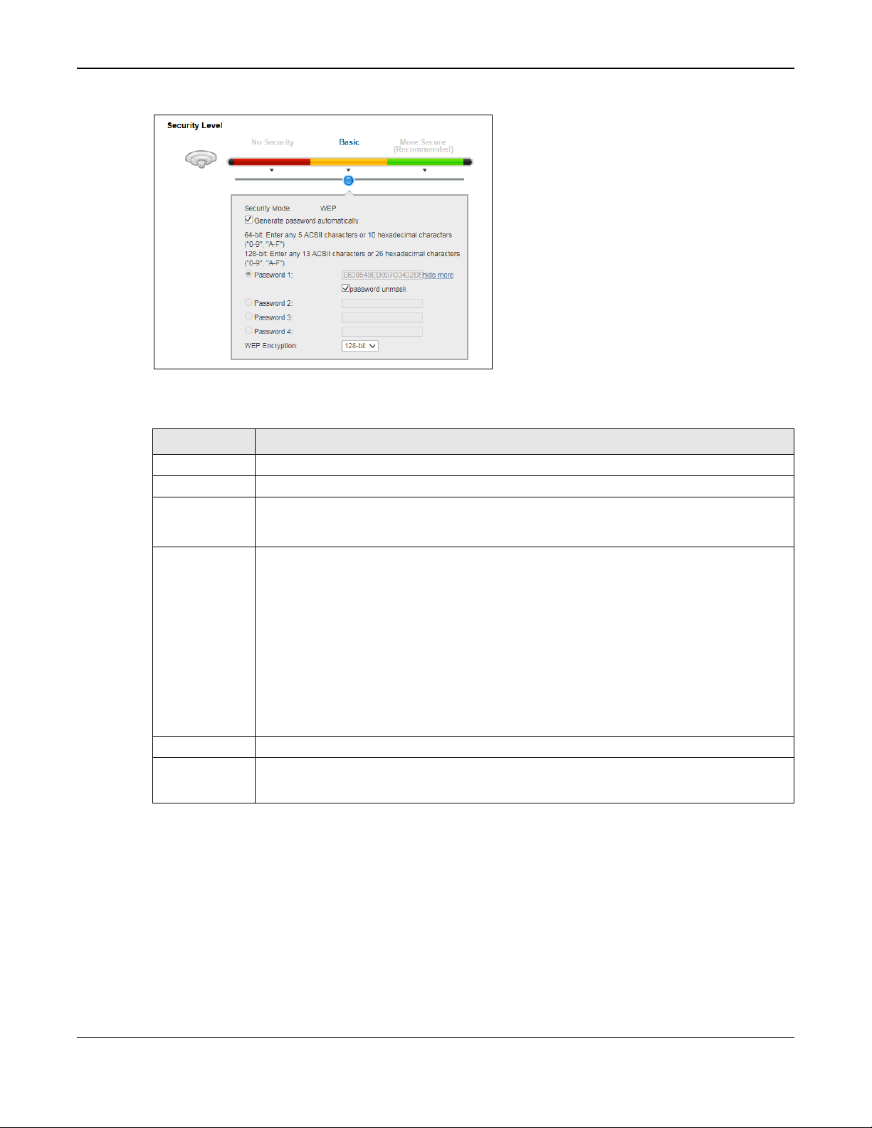
Chapter 7 Wireless
Security Level
Select Basic to enable WEP data encryption.
Security Mode
This shows WEP when you set Security Level to Basic.
Generate
Select this option to have the VMG automatically generate a passwo rd. The password field
Password 1~4
more.../hide
Click more... to show more fields in this section. Click hide to hide them.
WEP Encryption
Select 64-bit or 128-bit.
Figure 35 Wireless > General: Basic (WEP)
The following table describes the labels in this screen.
Table 19 Wireless > General: Basic (WEP)
LABEL
DESCRIPTION
password
automatically
will not be configurable when you select this option.
The password (WEP keys) are used to encrypt data. Both the VMG and the wireless stations
must use the same password (WEP key) for data transmission.
If you chose 64-bit WEP, then enter any 5 ASCII characters or 10 hexadecimal characters
("0-9", "A-F").
If you chose 128-bit WEP, then enter 13 ASCII characters or 26 hexadecimal characters
("0-9", "A-F").
You must configure at least one password, only one password can be activated at any one
time.
Select password unmask to display the entered password in plain text. Clear it to hide the
password to avoid shoulder surfing.
This dictates the length of the security key that the network is going to use.
7.2.3 More Secure (WPA(2)-PSK)
The WPA-PSK security mode provides both improved data encryption and user authent i c a t ion over
WEP. Using a Pre-Shared Key (PSK), both the VMG and the connecting client share a common
password in order to validate the connection. This type of encryption, while robust, is not as strong
as WPA, WPA2 or even WPA2-PSK. The WPA2-PSK security mode is a newer, more robust version of
the WPA encryption standard. It offers slightly better security, although the use of PSK makes it
less robust than it could be.
Click Network Setting > Wireless to display the General screen. Select More Secure as the
security level.
VMG1312-B10D User’s Guide
92
Page 93

Chapter 7 Wireless
Note: WPA-PSK or
WPA-WPA2-Personal
is not available if you enable WPS before you
configure them.
Figure 36 Wireless > General: More Secure: WPA2-PSK
The following table describes the labels in this screen.
Table 20 Wireless > General: More Secure: WPA2-PSK
LABEL
Security Level Select More Secure to enable WPA2-PSK data encryption.
Security Mode Select WPA-PSK, WPA2-PSK or WPA-WPA2-Personal from the drop-down list box.
Generate
password
automatically
Password
DESCRIPTION
Select this option to have the VMG automatically generate a password. The password field
will not be configurable when you select this option.
If you did not select Generate password automatically, you can manually type a pre-
shared key from 8 to 64 case-sensitive keyboard characters.
7.3 The Guest/More AP Screen
Select password unmask to display the entered password in plain text. Clear it to hide the
password to avoid shoulder surfing.
more.../hide
Encryption
Group Key
Update Timer
This screen allows you to enable and configure multiple Ba s ic Service Sets (BSSs) on the VMG.
Click Network Setting > Wireless > Guest/More AP. The following screen displays.
Click more... to show more fields in this section. Click hide to hide them.
Select the encryption type (TKIP, AES or TKIP+AES) for data encryption.
Select TKIP if your wireless clients can all use TKIP.
Select AES if your wireless clients can all use AES.
Select TKIP+AES to allow the wireless clients to use either TKIP or AES.
The Group Key Update Timer is the rate at which the RADIUS server sends a new group
key out to all clients.
VMG1312-B10D User’s Guide
93
Page 94

Chapter 7 Wireless
#
This is the index number of the entry.
Status
This field indicates whether this SSID is active. A yellow bulb signifies that this SSID is active.
SSID
An SSID profile is the set of parameters relating to one of the VMG’s BSSs. The SSID (Service
Security
This field indicates the security mode of the SSID profile.
Guest WLAN
This displays if the guest WLAN function has been enabled for this WLAN.
Modify
Click the Edit icon to configure the SSID profile.
Figure 37 Network Setting > Wireless > Guest/More AP
The following table describes the labels in this screen.
Table 21 Network Setting > Wireless > Guest/More AP
LABEL
DESCRIPTION
A gray bulb signifies that this SSID is not active.
Set IDentifier) identifies the Service Set with which a wireless device is associated.
This field displays the name of the wireless profile on the network. When a wireless client
scans for an AP to associate with, this is the name that is broadcast and seen in the wireless
client utility.
If Home Guest displays, clients connecting to the same SSID can communicate with each
other directly.
If External Guest displays, clients are blocked from connecting to each other directly.
N/A displays if guest WLAN is disabled.
7.3.1 Edit Guest/More AP
Use this screen to edit an SSID profile. Click the Edit icon next to an SSID in the Guest/More AP
screen. The following screen displays.
VMG1312-B10D User’s Guide
94
Page 95

Chapter 7 Wireless
Enable
Disable
Figure 38 Network Setting > Wireless > Guest/More AP > Edit
The following table describes the field s in this screen.
Table 22 Network Setting > Wireless > Guest/More AP > Edit
LABEL
Wireless Network Setup
Wireless
Passphrase
Type
DESCRIPTION
You can
If you set security for the wireless LAN and have the VMG generate a password, the setting
in this field determines how the VMG generates the password.
Select None to set the VMG’s password generation to not be based on a passphrase.
or
the wireless LAN in this field.
Select Fixed to use a 16 character passphrase for generating a password.
Select Variable to use a 16 to 63 character passphrase for generating a password.
VMG1312-B10D User’s Guide
95
Page 96

Chapter 7 Wireless
Guest WLAN
Home Guest
Enable
DHCP Start
DHCP End
LAN IP
Basic (WEP
More Secure (WPA-PSK, WPA2-PSK, WPA-WPA2-Personal
OK
Cancel
Table 22 Network Setting > Wireless > Guest/More AP > Edit (continued)
LABEL
Passphrase Key
Wireless Network Settings
Wireless
Network Name
(SSID)
Hide SSID
Multicast
Forwarding
Access
Scenario
DESCRIPTION
For a fixed type passphrase enter 16 alphanumeric characters (0-9, A-Z, with no spaces). It
must contain both letters and numbers and is case-sensitive.
For a variable type passphrase enter 16 to 63 alphanumeric characters (0-9, A-Z, with no
spaces). It must contain both letters and numbers and is case-sensitive.
The SSID (Service Set IDentity) identifies the service set with which a wireless device is
associated. Wireless devices associating to the access point (AP) must have the same SSID.
Enter a descriptive name (up to 32 English keyboard characters) for the wireless LAN.
Select this check box to hide the SSID in the outgoing beacon frame so a station cannot
obtain the SSID through scanning using a site survey tool.
Select this check box to allow the VMG to convert wireless multicast traffic into wireless
unicast traffic.
Select this to create Guest WLANs for home and external clients. Select the WLAN type in
the Access Scenario field.
If you select
other directly.
If you select External Guest, clients are blocked from connecting to each other directly.
, clients connecting to the same SSID can communicate with each
Move your mouse over the network icon next to the drop-down list box to view the
corresponding network topology.
Max. Upstream
Bandwidth
Max.
Downstream
Bandwidth
SSID Subnet
Address
Address
SSID
Subnet
Mask
Address
Security Level
Security Mode Select
Specify the maximum rate for upstream wireless traffic to the WAN from this WLAN in
kilobits per second (Kbps).
Specify the maximum rate for downstream wireless traffic to this WLAN from the WAN in
kilobits per second (Kbps).
Select
associated wireless clients.
Specify the first of the contiguous addresses in the DHCP IP address pool.
The VMG assigns IP addresses from this DHCP pool to wireless clients connecting to the
SSID.
Specify the last of the contiguous addresses in the DHCP IP address pool.
Specify the subnet mask of the VMG for the SSID subnet.
Specify the IP address of the VMG for the SSID subnet.
add security on this wireless network. The wireless clients which want to associate to this
network must have same wireless security settings as the VMG. After you select to use a
security, additional options appears in this screen.
Or you can select No Security to allow any client to associate this network without any data
encryption or authentication.
if you want the wireless network interface to assign DHCP IP addresses to the
) or
) to
See Section 7.2.1 on page 91 for more details about this field.
OK
Cancel
Click
Click
to save your changes.
to exit this screen without saving.
VMG1312-B10D User’s Guide
96
Page 97

Chapter 7 Wireless
General
SSID
Select the SSID for which you want to configure MAC filter settings.
MAC Restrict
Define the filter action for the list of MAC addresses in the MAC address list.
MAC address List
Add new MAC
Click this if you want to add a new MAC address entry to the MAC filter list below. This
#
This is the index number of the entry.
MAC Address
This is the MAC addresses of the wireless devices that are allowed or denied access to the
Modify
Click the Edit icon to change the MAC address.
Apply
Click Apply to save your changes.
Cancel
Click Cancel to restore your previously saved settings.
7.4 The MAC Authentication S cr een
This screen allows you to configure the VMG to give exclusive access to specific devices (Allow) or
exclude specific devices from accessing the VMG (Deny). Every Ethernet device has a unique MAC
(Media Access Control) address. The MAC address is assigned at the factory and consists of six
pairs of hexadecimal characters, for example, 00:A0:C5:01:23:45. You need to know the MAC
addresses of the devices to configure this screen.
Use this screen to view your VMG’s MAC filter settings and add new MAC filter rules. Click Network
Setting > Wireles s > MAC Authentication. The screen appears as shown.
Figure 39 Network Setting > Wireless > MAC Authentication
The following table describes the labels in this screen.
Table 23 Network Setting > Wireless > Authentication
LABEL
DESCRIPTION
Mode
address
Select Disable to turn off MAC filtering.
Select Deny to block access to the VMG. MAC addresses not listed will be allowed to access
the VMG.
Select Allow to permit access to the VMG. MAC addresses not listed will be denied access
to the VMG.
button is not configurable when you select Disable in the MAC Restrict Mode field.
Enter the MAC addresses of the wireless devices that are allowed or denied access to the
VMG. Enter the MAC addresses in a valid MAC address format, that is, six hexadecimal
character pairs, for example, 12:34:56:78:9a:bc.
VMG.
Click the Delete icon to remove the entry.
VMG1312-B10D User’s Guide
97
Page 98
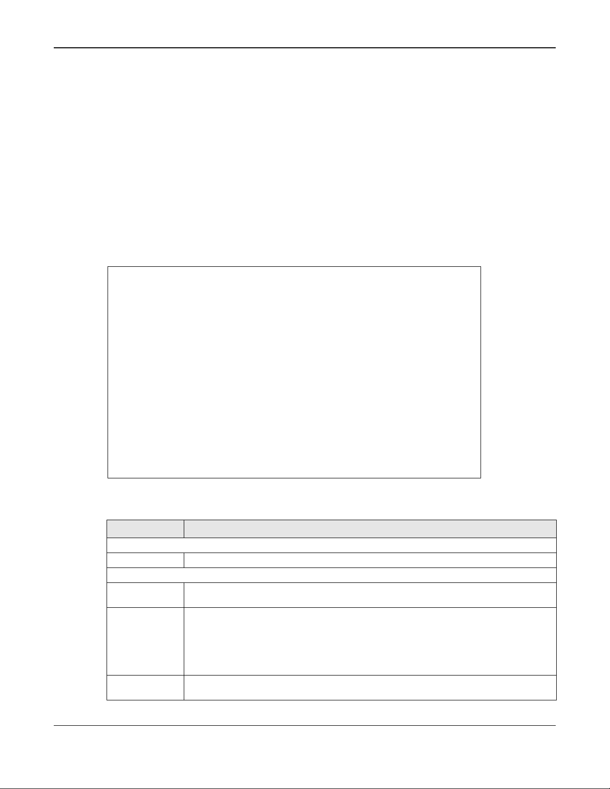
Chapter 7 Wireless
7.5 The WPS Screen
Use this screen to configure WiFi P rotected Setup (WPS) on your VMG.
WPS allows you to quickly set up a wireless network with strong security, without having to
configure security settings manually. Set up each WPS connection between two devices. Both
devices must support WPS. See Section 7.9.8.3 on page 111 for more information about WPS.
Note: The VMG applies the security settings of the SSID1 profile (see Section 7.2 on
page 88). If you want to use the WPS feature, make sure you have set the security
mode of SSID1 to WPA2-PSK or No Security.
Click Network Setting > Wireless > WPS. The following screen displays. Select Enable and click
Apply to activate the WPS function. Then you can configure the WPS settings in this screen.
Figure 40 Network Setting > Wireless > WPS
The following table describes the labels in this screen.
Table 24 Network Setting > Wireless > WPS
LABEL
General
WPS
Add a new device with WPS Method
Method 1
WPS
DESCRIPTION
Select Enable to activate WPS on this VMG.
Use this section to set up a WPS wireless network using Push Button Configuration (PBC).
Select Enable and click Apply to activate WPS method 1 on the VMG.
Click this button to add another WPS-enabled wireless device (within wireless range of the
VMG) to your wireless network. This button may either be a physical button on the outside
of device, or a menu button similar to the WPS button on this screen.
Method 2
Note: You must press the other wireless device’s WPS button within two minutes of pressing
this button.
Use this section to set up a WPS wireless network by entering the PIN of the client into the
VMG. Select Enable and click Apply to activate WPS method 2 on the VMG.
VMG1312-B10D User’s Guide
98
Page 99

Chapter 7 Wireless
Release
Generate
Apply
Cancel
Table 24 Network Setting > Wireless > WPS (continued)
LABEL
Register
Method 3
Configuration
New PIN
Number
Apply
Cancel
DESCRIPTION
Enter the PIN of the device that you are setting up a WPS connection with and click
Register to authenticate and add the wireless device to your wireless network.
You can find the PIN either on the outside of the device, or by checking the device’s
settings.
Note: You must also activate WPS on that device within two minutes to have it present its
PIN to the VMG.
Use this section to set up a WPS wireless network by entering the PIN of the VMG into the
client. Select Enable and click Apply to activate WPS method 3 on the VMG.
The default WPS status is configured.
Click this button to remove all configured wireless and wireless security settings for WPS
connections on the VMG.
If this method has been enabled, the PIN (Personal Identification Number) of the VMG is
shown here. Enter this PIN in the configuration utility of the device you want to connect to
using WPS.
The PIN is not necessary when you use WPS push-button method.
Click the Generate New PIN button to have the VMG create a new PIN.
Click
Click
to save your changes.
to restore your previously saved settings.
7.6 The WMM Screen
Use this screen to enable Wi-Fi MultiMedia (WMM) and WMM Power Save in wireless networks for
multimedia applications.
Click Network Setting > Wireless > WMM. The following screen displays.
Figure 41 Network Setting > Wireless > WMM
VMG1312-B10D User’s Guide
99
Page 100
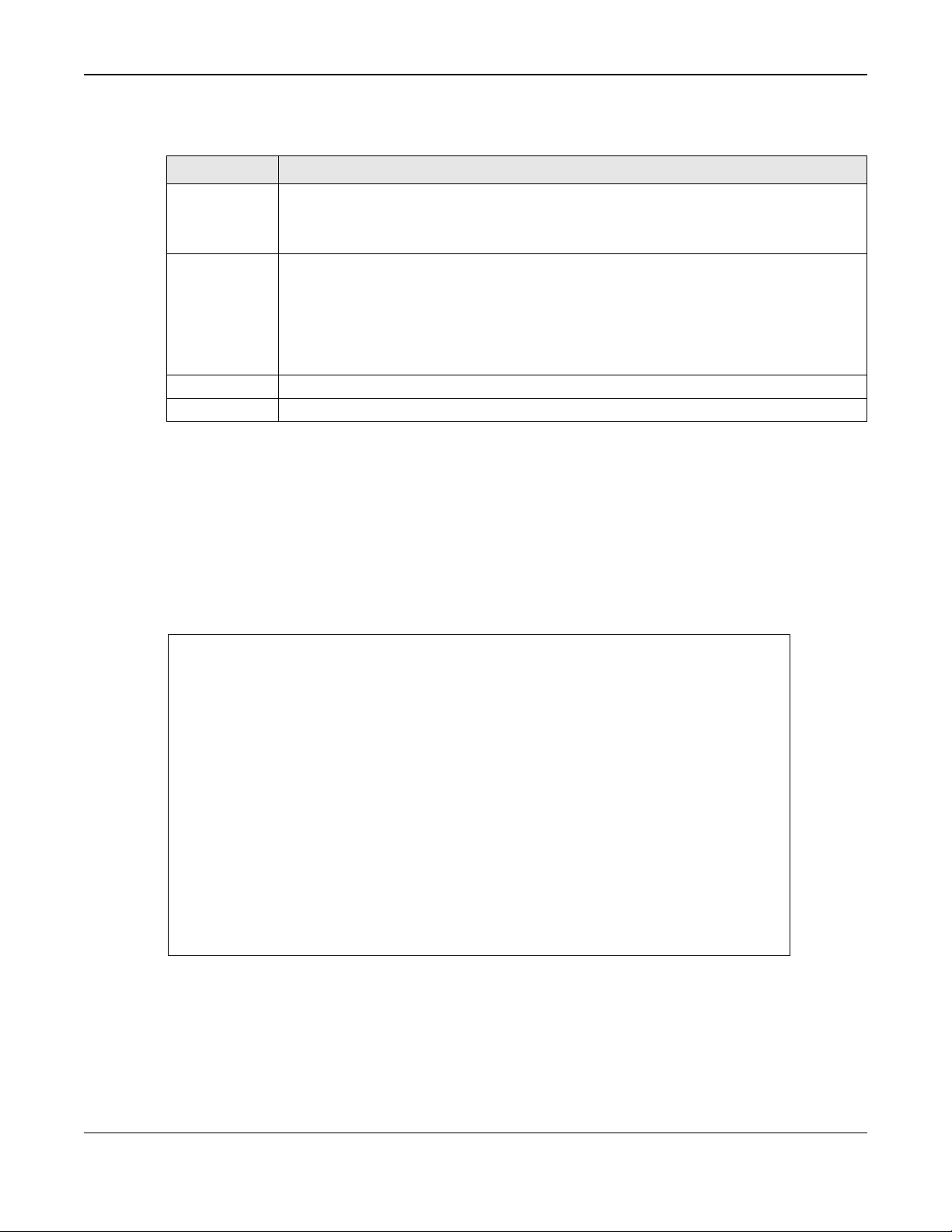
Chapter 7 Wireless
The following table describes the labels in this screen.
Table 25 Network Setting > Wireless > WMM
LABEL
WMM of
SSID1~4
WMM Automatic
Power Save
Delivery(APSD)
Apply
Cancel
DESCRIPTION
Select On to have the VMG automatically give the wireless network (SSIDx) a priority level
according to the ToS value in the IP header of packets it sends. WMM QoS (Wifi MultiMedia
Quality of Service) gives high priority to voice and video, which makes them run more
smoothly.
Select this option to extend the battery life of your mobile devices (especially useful for
small devices that are running multimedia applications). The VMG goes to sleep mode to
save power when it is not transmitting data. The AP buffers the packets sent to the VMG
until the VMG "wakes up". The VMG wakes up periodically to check for incoming data.
Note: This works only if the wireless device to which the VMG is connected also supports this
Click Apply to save your changes.
Click Cancel to restore your previously saved settings.
feature.
7.7 The Others Screen
Use this screen to configure advanced wireless settings. Click Network Setting > Wireless >
Others. The screen appears as shown.
See Section 7.9.2 on page 105 for detailed definitions of the terms listed in this screen.
Figure 42 Network Setting > Wireless > Others
VMG1312-B10D User’s Guide
10
 Loading...