


P-2302R Series
VoIP Station Gateway
User’s Guide
Version 3.60
12/2005


P-2302R Series User’s Guide
Copyright
Copyright © 2005 by ZyXEL Communications Corporation.
The contents of this publication may not be reproduced in any part or as a whole, transcribed,
stored in a retrieval system, translated into any language, or transmitted in any form or by any
means, electronic, mechanical, magnetic, optical, chemical, photocopying, manual, or
otherwise, without the prior written permission of ZyXEL Communications Corporation.
Published by ZyXEL Communications Corporation. All rights reserved.
Disclaimer
ZyXEL does not assume any liability arising out of the application or use of any products, or
software described herein. Neither does it convey any license under its patent rights nor the
patent rights of others. ZyXEL further reserves the right to make changes in any products
described herein without notice. This publication is subject to change without notice.
Trademarks
ZyNOS (ZyXEL Network Operating System) is a registered trademark of ZyXEL
Communications, Inc. Other trademarks mentioned in this publication are used for
identification purposes only and may be properties of their respective owners.
Copyright 2

P-2302R Series User’s Guide
Federal Communications
Commission (FCC) Interference
Statement
This device complies with Part 15 of FCC rules. Operation is subject to the following two
conditions:
• This device may not cause harmful interference.
• This device must accept any interference received, including interference that may cause
undesired operations.
This equipment has been tested and found to comply with the limits for a Class B digital
device pursuant to Part 15 of the FCC Rules. These limits are designed to provide reasonable
protection against harmful interference in a commercial environment. This equipment
generates, uses, and can radiate radio frequency energy, and if not installed and used in
accordance with the instructions, may cause harmful interference to radio communications.
If this equipment does cause harmful interference to radio/television reception, which can be
determined by turning the equipment off and on, the user is encouraged to try to correct the
interference by one or more of the following measures:
• Reorient or relocate the receiving antenna.
• Increase the separation between the equipment and the receiver.
• Connect the equipment into an outlet on a circuit different from that to which the receiver
is connected.
• Consult the dealer or an experienced radio/TV technician for help.
Notice 1
Changes or modifications not expressly approved by the party responsible for compliance
could void the user's authority to operate the equipment.
This Class B digital apparatus complies with Canadian ICES-003.
Cet appareil numérique de la classe B est conforme à la norme NMB-003 du Canada.
Certifications
1 Go to www.zyxel.com.
2 Select your product from the drop-down list box on the ZyXEL home page to go to that
product's page.
3 Select the certification you wish to view from this page.
3 Federal Communications Commission (FCC) Interference Statement

P-2302R Series User’s Guide
Federal Communications Commission (FCC) Interference Statement 4

P-2302R Series User’s Guide
For your safety, be sure to read and follow all warning notices and instructions.
• To reduce the risk of fire, use only No. 26 AWG (American Wire Gauge) or larger
telecommunication line cord.
• Do NOT open the device or unit. Opening or removing covers can expose you to
dangerous high voltage points or other risks. ONLY qualified service personnel can
service the device. Please contact your vendor for further information.
• Use ONLY the dedicated power supply for your device. Connect the power cord or
power adaptor to the right supply voltage (110V AC in North America or 230V AC in
Europe).
• Do NOT use the device if the power supply is damaged as it might cause electrocution.
• If the power supply is damaged, remove it from the power outlet.
• Do NOT attempt to repair the power supply. Contact your local vendor to order a new
power supply.
• Place connecting cables carefully so that no one will step on them or stumble over them.
Do NOT allow anything to rest on the power cord and do NOT locate the product where
anyone can walk on the power cord.
• If you wall mount your device, make sure that no electrical, gas or water pipes will be
damaged.
• Do NOT install nor use your device during a thunderstorm. There may be a remote risk of
electric shock from lightning.
• Do NOT expose your device to dampness, dust or corrosive liquids.
• Do NOT use this product near water, for example, in a wet basement or near a swimming
pool.
• Make sure to connect the cables to the correct ports.
• Do NOT obstruct the device ventilation slots, as insufficient airflow may harm your
device.
• Do NOT store things on the device.
• Connect ONLY suitable accessories to the device.
Safety Warnings
5 Safety Warnings

P-2302R Series User’s Guide
ZyXEL Limited Warranty
ZyXEL warrants to the original end user (purchaser) that this product is free from any defects
in materials or workmanship for a period of up to two years from the date of purchase. During
the warranty period, and upon proof of purchase, should the product have indications of failure
due to faulty workmanship and/or materials, ZyXEL will, at its discretion, repair or replace the
defective products or components without charge for either parts or labor, and to whatever
extent it shall deem necessary to restore the product or components to proper operating
condition. Any replacement will consist of a new or re-manufactured functionally equivalent
product of equal or higher value, and will be solely at the discretion of ZyXEL. This warranty
shall not apply if the product has been modified, misused, tampered with, damaged by an act
of God, or subjected to abnormal working conditions.
Note
Repair or replacement, as provided under this warranty, is the exclusive remedy of the
purchaser. This warranty is in lieu of all other warranties, express or implied, including any
implied warranty of merchantability or fitness for a particular use or purpose. ZyXEL shall in
no event be held liable for indirect or consequential damages of any kind to the purchaser.
To obtain the services of this warranty, contact ZyXEL's Service Center for your Return
Material Authorization number (RMA). Products must be returned Postage Prepaid. It is
recommended that the unit be insured when shipped. Any returned products without proof of
purchase or those with an out-dated warranty will be repaired or replaced (at the discretion of
ZyXEL) and the customer will be billed for parts and labor. All repaired or replaced products
will be shipped by ZyXEL to the corresponding return address, Postage Paid. This warranty
gives you specific legal rights, and you may also have other rights that vary from country to
country.
Registration
Register your product online to receive e-mail notices of firmware upgrades and information
at www.zyxel.com for global products, or at www.us.zyxel.com for North American products.
ZyXEL Limited Warranty 6

P-2302R Series User’s Guide
Please have the following information ready when you contact customer support.
• Product model and serial number.
• Warranty Information.
• Date that you received your device.
• Brief description of the problem and the steps you took to solve it.
Customer Support
METHOD
LOCATION
CORPORATE
HEADQUARTERS
(WORLDWIDE)
CZECH REPUBLIC
DENMARK
FINLAND
FRANCE
GERMANY
HUNGARY
KAZAKHSTAN
NORTH AMERICA
NORWAY
SUPPORT E-MAIL TELEPHONE
SALES E-MAIL FAX FTP SITE
support@zyxel.com.tw +886-3-578-3942 www.zyxel.com
sales@zyxel.com.tw +886-3-578-2439 ftp.zyxel.com
info@cz.zyxel.com +420-241-091-350 www.zyxel.cz ZyXEL Communications
info@cz.zyxel.com +420-241-091-359
support@zyxel.dk +45-39-55-07-00 www.zyxel.dk ZyXEL Communications A/S
sales@zyxel.dk +45-39-55-07-07
support@zyxel.fi +358-9-4780-8411 www.zyxel.fi ZyXEL Communications Oy
sales@zyxel.fi +358-9-4780 8448
info@zyxel.fr +33-4-72-52-97-97 www.zyxel.fr ZyXEL France
+33-4-72-52-19-20
support@zyxel.de +49-2405-6909-0 www.zyxel.de ZyXEL Deutschland GmbH.
sales@zyxel.de +49-2405-6909-99
support@zyxel.hu +36-1-3361649 www.zyxel.hu ZyXEL Hungary
info@zyxel.hu +36-1-3259100
http://zyxel.kz/support +7-3272-590-698 www.zyxel.kz ZyXEL Kazakhstan
sales@zyxel.kz +7-3272-590-689
support@zyxel.com 1-800-255-4101
+1-714-632-0882
sales@zyxel.com +1-714-632-0858 ftp.us.zyxel.com
support@zyxel.no +47-22-80-61-80 www.zyxel.no ZyXEL Communications A/S
sales@zyxel.no +47-22-80-61-81
A
WEB SITE
www.europe.zyxel.com
ftp.europe.zyxel.com
www.us.zyxel.com ZyXEL Communications Inc.
REGULAR MAIL
ZyXEL Communications Corp.
6 Innovation Road II
Science Park
Hsinchu 300
Ta iw a n
Czech s.r.o.
Modranská 621
143 01 Praha 4 - Modrany
Ceská Republika
Columbusvej
2860 Soeborg
Denmark
Malminkaari 10
00700 Helsinki
Finland
1 rue des Vergers
Bat. 1 / C
69760 Limonest
France
Adenauerstr. 20/A2 D-52146
Wuerselen
Germany
48, Zoldlomb Str.
H-1025, Budapest
Hungary
43, Dostyk ave.,Office 414
Dostyk Business Centre
050010, Almaty
Republic of Kazakhstan
1130 N. Miller St.
Anaheim
CA 92806-2001
U.S.A.
Nils Hansens vei 13
0667 Oslo
Norway
7 Customer Support

P-2302R Series User’s Guide
METHOD
LOCATION
POLAND
RUSSIA
SPAIN
SWEDEN
UKRAINE
UNITED KINGDOM
a. “+” is the (prefix) number you enter to make an international telephone call.
SUPPORT E-MAIL TELEPHONE
SALES E-MAIL FAX FTP SITE
info@pl.zyxel.com +48-22-5286603 www.pl.zyxel.com ZyXEL Communications
+48-22-5206701
http://zyxel.ru/support +7-095-542-89-29 www.zyxel.ru ZyXEL Russia
sales@zyxel.ru +7-095-542-89-25
support@zyxel.es +34-902-195-420 www.zyxel.es ZyXEL Communications
sales@zyxel.es +34-913-005-345
support@zyxel.se +46-31-744-7700 www.zyxel.se ZyXEL Communications A/S
sales@zyxel.se +46-31-744-7701
support@ua.zyxel.com +380-44-247-69-78 www.ua.zyxel.com ZyXEL Ukraine
sales@ua.zyxel.com +380-44-494-49-32
support@zyxel.co.uk +44-1344 303044
08707 555779 (UK only)
sales@zyxel.co.uk +44-1344 303034 ftp.zyxel.co.uk
A
WEB SITE
REGULAR MAIL
ul.Emilli Plater 53
00-113 Warszawa
Poland
Ostrovityanova 37a Str.
Moscow, 117279
Russia
Alejandro Villegas 33
1º, 28043 Madrid
Spain
Sjöporten 4, 41764 Göteborg
Sweden
13, Pimonenko Str.
Kiev, 04050
Ukraine
www.zyxel.co.uk ZyXEL Communications UK
Ltd.,11 The Courtyard,
Eastern Road, Bracknell,
Berkshire, RG12 2XB,
United Kingdom (UK)
•
Customer Support 8

P-2302R Series User’s Guide
9 Customer Support

P-2302R Series User’s Guide
Table of Contents
Copyright ..................................................................................................................2
Federal Communications Commission (FCC) Interference Statement ............... 3
Safety Warnings ....................................................................................................... 5
ZyXEL Limited Warranty.......................................................................................... 6
Customer Support.................................................................................................... 7
Table of Contents ...................................................................................................10
List of Figures ........................................................................................................ 22
List of Tables .......................................................................................................... 28
Preface ....................................................................................................................32
Chapter 1
Introducing the Prestige........................................................................................ 34
1.1 Prestige 2302R VoIP Station Gateway Series Overview ...................................34
1.2 Prestige 2302RL VoIP Analog Telephone Adaptor with Lifeline .........................34
1.3 Features .............................................................................................................34
1.4 LEDs ..................................................................................................................39
1.5 Applications ........................................................................................................40
1.5.1 Make Calls via Internet Telephony Service Provider ................................40
1.5.2 Make Calls via IP-PBX ..............................................................................41
1.5.3 Make Peer-to-peer Calls ...........................................................................42
Chapter 2
Introducing the Web Configurator........................................................................ 44
2.1 Web Configurator Overview ...............................................................................44
2.2 Accessing the Prestige Web Configurator .........................................................44
2.3 Resetting the Prestige ........................................................................................45
2.3.1 Procedure To Use The Reset Button ........................................................45
2.4 Navigating the Prestige Web Configurator .........................................................46
2.5 Common Screen Command Buttons .................................................................49
Chapter 3
Wizard Setup .......................................................................................................... 50
3.1 Wizard Setup Overview ......................................................................................50
Table of Contents 10

P-2302R Series User’s Guide
3.2 Wizard 1: General Setup ....................................................................................50
3.2.1 Domain Name ...........................................................................................50
3.3 Wizard 2: ISP Parameters for Internet Access ...................................................51
3.3.1 Ethernet ....................................................................................................51
3.3.2 PPPoE Encapsulation ...............................................................................52
3.4 Wizard 3: WAN Setup ........................................................................................54
3.5 Wizard 4: SIP 1 Setup ........................................................................................56
3.6 Wizard Setup Complete .....................................................................................59
Chapter 4
System Screens ..................................................................................................... 62
4.1 System Overview ...............................................................................................62
4.2 DNS Overview ....................................................................................................62
4.3 General Screen ..................................................................................................62
4.3.1 Domain Name ...........................................................................................63
4.3.2 DNS Server Address Assignment .............................................................63
4.4 System General Configuration ...........................................................................63
4.5 Dynamic DNS .....................................................................................................65
4.5.1 DynDNS Wildcard .....................................................................................65
4.6 Configuring Dynamic DNS .................................................................................65
4.7 Configuring Password ........................................................................................67
4.8 Pre-defined NTP Time Servers List ....................................................................68
4.9 Configuring Time Setting ....................................................................................68
4.9.1 Resetting the Time ....................................................................................70
Chapter 5
LAN Setup............................................................................................................... 72
5.1 LAN Overview ....................................................................................................72
5.2 IP Address and Subnet Mask .............................................................................72
5.3 DHCP Setup .......................................................................................................73
5.3.1 IP Pool Setup ............................................................................................73
5.4 LAN TCP/IP ........................................................................................................73
5.4.1 Factory LAN Defaults ................................................................................73
5.5 DNS Server Address ..........................................................................................73
5.6 RIP Setup ...........................................................................................................74
5.7 Multicast .............................................................................................................75
5.8 Any IP .................................................................................................................75
5.8.0.1 How Any IP Works ..........................................................................76
5.9 Configuring LAN .................................................................................................77
5.10 Configuring IP Alias ..........................................................................................79
11 Table of Contents

P-2302R Series User’s Guide
Chapter 6
WAN Screens.......................................................................................................... 82
6.1 WAN Overview ...................................................................................................82
6.2 Configuring ISP ..................................................................................................82
6.2.1 Ethernet Encapsulation .............................................................................82
6.2.2 PPPoE Encapsulation ...............................................................................83
6.3 WAN IP Address Assignment .............................................................................85
6.4 Configuring WAN IP ...........................................................................................85
6.5 Configuring WAN MAC .......................................................................................88
Chapter 7
Introduction to VoIP ............................................................................................... 90
7.1 VoIP Introduction ................................................................................................90
7.2 Introduction to SIP ..............................................................................................90
7.2.1 SIP Identities .............................................................................................90
7.2.1.1 SIP Number .....................................................................................90
7.2.1.2 SIP Service Domain ........................................................................91
7.2.2 SIP Call Progression .................................................................................91
7.2.3 SIP Client Server ......................................................................................91
7.2.3.1 SIP User Agent ...............................................................................92
7.2.3.2 SIP Proxy Server .............................................................................92
7.2.3.3 SIP Redirect Server ........................................................................93
7.2.3.4 SIP Register Server ........................................................................93
7.2.4 RTP ...........................................................................................................93
7.3 NAT ....................................................................................................................94
7.3.1 NAT Example ............................................................................................94
7.3.2 NAT Types ................................................................................................95
7.3.2.1 Full Cone NAT .................................................................................96
7.3.2.2 Restricted Cone NAT .......................................................................96
7.3.2.3 Port Restricted Cone NAT ...............................................................97
7.3.2.4 Symmetric NAT ...............................................................................98
7.4 NAT and SIP ......................................................................................................99
7.5 SIP ALG .............................................................................................................99
7.6 Use NAT .............................................................................................................99
7.7 STUN ...............................................................................................................100
7.8 Outbound Proxy ...............................................................................................100
7.9 Voice Coding ....................................................................................................100
7.9.1 Pulse Code Modulation ...........................................................................101
7.9.2 G.711 .......................................................................................................101
7.9.3 G.729 ......................................................................................................101
7.10 PSTN Call Setup Signaling ............................................................................101
7.11 MWI (Message Waiting Indication) .................................................................101
Table of Contents 12

P-2302R Series User’s Guide
Chapter 8
VoIP Screens......................................................................................................... 102
8.1 VoIP Introduction ..............................................................................................102
8.2 VoIP Configuration ...........................................................................................102
8.3 Custom Tones (IVR) .........................................................................................104
8.4 Advanced VoIP Settings Configuration ............................................................105
8.5 Quality of Service (QoS) ..................................................................................109
8.5.1 Type Of Service (ToS) ............................................................................. 110
8.5.2 DiffServ ................................................................................................... 110
8.5.3 VLAN ......................................................................................................110
8.6 QoS Configuration ............................................................................................ 111
Chapter 9
Phone .................................................................................................................... 112
8.3.0.1 Recording Custom Tones ..............................................................105
8.3.0.2 Listening to Custom Tones ............................................................105
8.3.0.3 Deleting Custom Tones .................................................................105
8.5.2.1 DSCP and Per-Hop Behavior ........................................................ 110
9.1 Phone Introduction ...........................................................................................112
9.1.1 Voice Activity Detection/Silence Suppression .........................................112
9.1.2 Comfort Noise Generation ...................................................................... 112
9.1.3 Echo Cancellation ...................................................................................112
9.2 Phone Port Configuration .................................................................................112
9.3 Supplementary Phone Services Overview .......................................................114
9.3.1 The Flash Key ......................................................................................... 114
9.3.2 Europe Type Supplementary Phone Services ........................................ 114
9.3.2.1 European Call Hold .......................................................................115
9.3.2.2 European Call Waiting .................................................................. 115
9.3.2.3 European Call Transfer .................................................................116
9.3.2.4 European Three-Way Conference ................................................ 116
9.3.3 USA Type Supplementary Services ........................................................116
9.3.3.1 USA Call Hold ............................................................................... 117
9.3.3.2 USA Call Waiting .......................................................................... 117
9.3.3.3 USA Call Transfer ......................................................................... 117
9.3.3.4 USA Three-Way Conference ......................................................... 117
9.4 Common Phone Configuration .........................................................................117
Chapter 10
Phone Book ..........................................................................................................120
10.1 Phone Book Introduction ................................................................................120
10.1.1 Speed Dial ............................................................................................120
10.1.1.1 Peer-to-Peer Calls .......................................................................120
10.1.2 Lifeline (Prestige 2302RL) ....................................................................120
13 Table of Contents

P-2302R Series User’s Guide
10.2 Speed Dial Configuration ...............................................................................120
10.3 Call Forward ...................................................................................................122
10.4 Lifeline Configuration (Prestige 2302RL) .......................................................125
Chapter 11
Phone Usage ........................................................................................................ 126
11.1 Dialing a Telephone Number ..........................................................................126
11.2 Using Speed Dial to Dial a Telephone Number ..............................................126
11.3 Internal Calls ..................................................................................................126
11.4 Checking the Prestige’s IP Address ...............................................................126
11.5 Auto Firmware Upgrade .................................................................................127
Chapter 12
Network Address Translation (NAT) Screens.................................................... 128
12.1 NAT Overview ................................................................................................128
12.1.1 NAT Definitions .....................................................................................128
12.1.2 What NAT Does ....................................................................................129
12.1.3 How NAT Works ...................................................................................129
12.1.4 NAT Application ....................................................................................130
12.1.5 NAT Mapping Types .............................................................................130
12.2 SUA (Single User Account) Versus NAT ........................................................131
12.3 SUA Server ....................................................................................................131
12.3.1 Default Server IP Address ....................................................................132
12.3.2 Port Forwarding: Services and Port Numbers ......................................132
12.3.3 Configuring Servers Behind SUA (Example) ........................................133
12.4 Configuring SUA Server .................................................................................133
12.5 Configuring Address Mapping ........................................................................135
12.5.1 Configuring Address Mapping ..............................................................137
12.6 Trigger Port Forwarding .................................................................................138
12.6.1 Trigger Port Forwarding Example .........................................................138
12.6.2 Two Points To Remember About Trigger Ports .....................................139
12.7 Configuring Trigger Port Forwarding ..............................................................139
Chapter 13
Static Route .......................................................................................................... 142
13.1 Static Route Overview ....................................................................................142
13.2 Configuring IP Static Route ............................................................................142
13.2.1 Configuring a Static Route Entry ...........................................................143
Chapter 14
Firewall.................................................................................................................. 146
14.1 Firewall Introduction .......................................................................................146
14.1.1 Stateful Inspection Firewall. ..................................................................146
Table of Contents 14

P-2302R Series User’s Guide
14.1.2 About the Prestige Firewall ...................................................................146
14.1.3 Guidelines For Enhancing Security With Your Firewall ........................147
14.2 Firewall Settings Screen ................................................................................147
14.3 The Firewall, NAT and Remote Management ................................................149
14.3.1 LAN-to-WAN rules ................................................................................149
14.3.2 WAN-to-LAN rules ................................................................................150
14.4 Services .........................................................................................................150
Chapter 15
Content Filtering .................................................................................................. 154
15.1 Introduction to Content Filtering .....................................................................154
15.2 Restrict Web Features ...................................................................................154
15.3 Days and Times .............................................................................................154
15.4 Configure Content Filtering ............................................................................154
Chapter 16
Remote Management Screens ............................................................................ 158
16.1 Remote Management Overview .....................................................................158
16.1.1 Remote Management Limitations .........................................................158
16.1.2 Remote Management and NAT ............................................................159
16.1.3 System Timeout ....................................................................................159
16.2 Configuring Telnet ..........................................................................................159
16.3 Configuring TELNET ......................................................................................159
16.4 Configuring FTP .............................................................................................160
16.5 Configuring WWW ..........................................................................................161
16.6 SNMP .............................................................................................................162
16.6.1 Supported MIBs ....................................................................................164
16.6.2 SNMP Traps .........................................................................................164
16.6.3 Configuring SNMP ................................................................................165
16.7 Configuring DNS ............................................................................................167
16.8 Configuring Security .......................................................................................168
Chapter 17
Universal Plug-and-Play (UPnP) ......................................................................... 170
17.1 Introducing Universal Plug and Play ..............................................................170
17.1.1 How do I know if I'm using UPnP? ........................................................170
17.1.2 NAT Traversal .......................................................................................170
17.1.3 Cautions with UPnP ..............................................................................170
17.2 UPnP and ZyXEL ...........................................................................................171
17.2.1 Configuring UPnP .................................................................................171
17.3 Installing UPnP in Windows Example ............................................................172
17.3.1 Installing UPnP in Windows Me ............................................................172
17.3.2 Installing UPnP in Windows XP ............................................................174
15 Table of Contents

P-2302R Series User’s Guide
17.4 Using UPnP in Windows XP Example ...........................................................176
17.4.1 Auto-discover Your UPnP-enabled Network Device .............................176
17.4.2 Web Configurator Easy Access ............................................................180
Chapter 18
Logs....................................................................................................................... 184
18.1 Configuring View Log .....................................................................................184
18.1.1 Log Message Descriptions ...................................................................185
18.1.2 Syslog Logs ..........................................................................................194
18.2 Configuring Log Settings ................................................................................195
Chapter 19
Bandwidth Management...................................................................................... 198
19.1 Bandwidth Management Overview ................................................................198
19.2 Bandwidth Classes and Filters .......................................................................198
19.3 Proportional Bandwidth Allocation .................................................................199
19.4 Application-based Bandwidth Management ...................................................199
19.5 Subnet-based Bandwidth Management .........................................................199
19.6 Application and Subnet-based Bandwidth Management ...............................199
19.7 Scheduler .......................................................................................................200
19.7.1 Priority-based Scheduler ......................................................................200
19.7.2 Fairness-based Scheduler ....................................................................200
19.8 Maximize Bandwidth Usage ...........................................................................200
19.8.1 Reserving Bandwidth for Non-Bandwidth Class Traffic ........................201
19.8.2 Maximize Bandwidth Usage Example ..................................................201
19.8.2.1 Priority-based Allotment of Unused and Unbudgeted Bandwidth 201
19.8.2.2 Fairness-based Allotment of Unused and Unbudgeted Bandwidth ...
202
19.9 Bandwidth Borrowing .....................................................................................202
19.9.1 Bandwidth Borrowing Example .............................................................203
19.9.2 Maximize Bandwidth Usage With Bandwidth Borrowing ......................203
19.10 Configuring Summary ..................................................................................203
19.11 Configuring Class Setup ...............................................................................205
19.11.1 Bandwidth Manager Class Configuration ............................................206
19.11.2 Bandwidth Management Statistics ......................................................208
19.12 Configuring Monitor ......................................................................................209
Chapter 20
Maintenance ......................................................................................................... 212
20.1 Maintenance Overview ...................................................................................212
20.2 Status Screen .................................................................................................212
20.2.1 System Statistics ...................................................................................214
20.3 DHCP Table Screen .......................................................................................215
Table of Contents 16

P-2302R Series User’s Guide
20.4 Any IP Table Screen .......................................................................................216
20.5 F/W Upload Screen ........................................................................................217
20.6 Configuration Screen .....................................................................................220
20.6.1 Backup Configuration ...........................................................................220
20.6.2 Restore Configuration ...........................................................................221
20.6.3 Back to Factory Defaults .......................................................................222
20.7 Restart Screen ...............................................................................................222
Chapter 21
Introducing the SMT ............................................................................................224
21.1 SMT Introduction ............................................................................................224
21.2 Accessing the SMT via Telnet ........................................................................224
21.3 Navigating the SMT Interface .........................................................................224
21.3.1 System Management Terminal Interface Summary ..............................226
21.3.2 Prestige SMT Menus Overview ............................................................227
21.4 Changing the System Password ....................................................................228
Chapter 22
General Setup....................................................................................................... 230
22.1 General Setup Introduction ............................................................................230
22.2 General Setup Configuration ..........................................................................230
22.2.1 Procedure to Configure Dynamic DNS .................................................231
Chapter 23
WAN Setup............................................................................................................ 234
23.1 Introduction to WAN .......................................................................................234
23.2 WAN Setup .....................................................................................................234
Chapter 24
LAN Setup............................................................................................................. 236
24.1 LAN Setup ......................................................................................................236
24.1.1 General Ethernet Setup ........................................................................236
24.2 TCP/IP Ethernet Setup and DHCP ................................................................237
24.2.1 IP Alias Setup .......................................................................................239
Chapter 25
Internet Access .................................................................................................... 242
25.1 Introduction to Internet Access Setup ............................................................242
25.2 Ethernet Encapsulation ..................................................................................242
25.3 Configuring the PPPoE Client ........................................................................243
25.4 Basic Setup Complete ....................................................................................244
17 Table of Contents

P-2302R Series User’s Guide
Chapter 26
Remote Node Configuration ............................................................................... 246
26.1 Introduction to Remote Node Setup ...............................................................246
26.2 Remote Node Profile Setup ...........................................................................246
26.2.1 Ethernet Encapsulation .........................................................................246
26.2.2 PPPoE Encapsulation ...........................................................................248
26.2.2.1 Outgoing Authentication Protocol ................................................249
26.2.2.2 Nailed-Up Connection .................................................................249
26.3 Edit IP .............................................................................................................250
26.4 Remote Node Filter ........................................................................................252
26.4.1 Traffic Redirect Setup ...........................................................................253
Chapter 27
Static Route Setup ............................................................................................... 256
27.1 Static Route Introduction ................................................................................256
27.2 IP Static Route Setup .....................................................................................256
Chapter 28
Network Address Translation (NAT)................................................................... 258
28.1 NAT Introduction ............................................................................................258
28.2 Applying NAT .................................................................................................258
28.3 NAT Setup ......................................................................................................259
28.3.1 Address Mapping Sets ..........................................................................260
28.3.1.1 User-Defined Address Mapping Sets ..........................................261
28.3.1.2 Ordering Your Rules ....................................................................262
28.4 Configuring a Server behind NAT ..................................................................264
28.5 General NAT Examples ..................................................................................265
28.5.1 Example 1: Internet Access Only ..........................................................265
28.5.2 Example 2: Internet Access with an Inside Server ...............................266
28.5.3 Example 3: Multiple Public IP Addresses With Inside Servers .............267
28.5.4 Example 4: NAT Unfriendly Application Programs ...............................270
28.6 Configuring Trigger Port Forwarding .............................................................271
Chapter 29
Enabling the Firewall ........................................................................................... 274
29.1 Remote Management and the Firewall ..........................................................274
29.2 Access Methods .............................................................................................274
29.3 Enabling the Firewall ......................................................................................274
Chapter 30
Filter Configuration.............................................................................................. 276
30.1 Introduction to Filters ......................................................................................276
30.1.1 The Filter Structure of the Prestige .......................................................277
Table of Contents 18

P-2302R Series User’s Guide
30.2 Configuring a Filter Set ..................................................................................278
30.2.1 Configuring a Filter Rule .......................................................................281
30.2.2 Configuring a TCP/IP Filter Rule ..........................................................281
30.2.3 Configuring a Generic Filter Rule .........................................................284
30.3 Example Filter ................................................................................................286
30.4 Filter Types and NAT ......................................................................................288
30.5 Applying a Filter ............................................................................................288
30.5.1 Applying LAN Filters .............................................................................289
30.5.2 Applying Remote Node Filters ..............................................................289
Chapter 31
SNMP Configuration ............................................................................................ 290
31.1 SNMP Introduction .........................................................................................290
31.2 SNMP Configuration ......................................................................................290
Chapter 32
System Information and Diagnosis .................................................................... 292
32.1 System Status ................................................................................................292
32.2 System Information ........................................................................................294
32.2.1 System Information ...............................................................................294
32.2.2 Console Port Speed ..............................................................................295
32.3 Log and Trace ................................................................................................296
32.3.1 Syslog Logging .....................................................................................296
32.3.1.1 CDR ............................................................................................298
32.3.1.2 Packet triggered ..........................................................................298
32.3.1.3 Filter log .....................................................................................299
32.3.1.4 PPP log ......................................................................................299
32.3.2 Call-Triggering Packet ..........................................................................299
32.4 Diagnostic ......................................................................................................300
32.4.1 WAN DHCP ..........................................................................................301
Chapter 33
Firmware and Configuration File Maintenance ................................................. 304
33.1 Filename Conventions ...................................................................................304
33.2 Backup Configuration .....................................................................................305
33.2.1 Backup Configuration ...........................................................................305
33.2.2 Using the FTP Command from the Command Line ..............................306
33.2.3 Example of FTP Commands from the Command Line .........................306
33.2.4 GUI-based FTP Clients .........................................................................307
33.2.5 TFTP and FTP over WAN Management Limitations .............................307
33.2.6 Backup Configuration Using TFTP .......................................................307
33.2.7 TFTP Command Example ....................................................................308
33.2.8 GUI-based TFTP Clients ......................................................................308
19 Table of Contents

P-2302R Series User’s Guide
33.3 Restore Configuration ....................................................................................309
33.3.1 Restore Using FTP ...............................................................................309
33.3.2 Restore Using FTP Session Example ..................................................310
33.4 Uploading Firmware and Configuration Files .................................................310
33.4.1 Firmware File Upload ............................................................................310
33.4.2 Configuration File Upload ..................................................................... 311
33.4.3 FTP File Upload Command from the DOS Prompt Example ................311
33.4.4 FTP Session Example of Firmware File Upload ...................................312
33.4.5 TFTP File Upload ..................................................................................312
33.4.6 TFTP Upload Command Example ........................................................313
Chapter 34
System Maintenance............................................................................................ 314
34.1 Command Interpreter Mode ...........................................................................314
34.1.1 Command Syntax .................................................................................314
34.1.2 Command Usage ..................................................................................315
34.2 Call Control Support .......................................................................................315
34.2.1 Budget Management ............................................................................315
34.2.2 Call History ...........................................................................................316
34.3 Time and Date Setting ....................................................................................317
Chapter 35
Remote Management ........................................................................................... 320
Chapter 36
Call Scheduling .................................................................................................... 322
Chapter 37
Troubleshooting ................................................................................................... 326
37.1 Problems Starting Up the Prestige .................................................................326
37.2 Problems with the LAN Interface ....................................................................326
37.3 Problems with the WAN Interface ..................................................................327
37.4 Problems with Internet Access .......................................................................327
37.5 Problems with the Password ..........................................................................327
37.6 Problems with the Web Configurator .............................................................328
37.7 Problems with a Telephone or the Telephone Port .........................................328
37.8 Problems with Voice Service ..........................................................................329
37.9 Pop-up Windows, JavaScripts and Java Permissions ...................................329
37.9.1 Internet Explorer Pop-up Blockers ........................................................329
37.9.1.1 Disable Pop-up Blockers .............................................................329
37.9.1.2 Enable Pop-up Blockers with Exceptions ....................................330
37.9.2 JavaScripts ...........................................................................................332
37.9.3 Java Permissions ..................................................................................334
37.9.3.1 JAVA (Sun) ..................................................................................335
Table of Contents 20

P-2302R Series User’s Guide
Appendix A
Product Specifications ........................................................................................ 338
Appendix B
Wall-mounting Instructions................................................................................. 342
Appendix C
Setting up Your Computer’s IP Address............................................................ 344
Appendix D
IP Subnetting ........................................................................................................ 356
Appendix E
PPPoE ................................................................................................................... 364
Appendix F
Triangle Route ...................................................................................................... 366
Appendix G
SIP Passthrough .................................................................................................. 370
Index...................................................................................................................... 372
21 Table of Contents

P-2302R Series User’s Guide
List of Figures
Figure 1 LEDs ..................................................................................................................... 40
Figure 2 Internet Telephony Service Provider Application .................................................. 41
Figure 3 IP-PBX Application ................................................................................................ 42
Figure 4 Peer-to-peer Calling .............................................................................................. 42
Figure 5 Web Site Address ................................................................................................. 44
Figure 6 Enter Password ..................................................................................................... 45
Figure 7 Change Password ................................................................................................ 45
Figure 8 Web Configurator .................................................................................................. 47
Figure 9 Wizard 1: General Setup ....................................................................................... 51
Figure 10 Wizard 2: Ethernet Encapsulation ....................................................................... 52
Figure 11 Wizard 2: PPPoE Encapsulation ......................................................................... 53
Figure 12 Wizard 3: WAN Setup ......................................................................................... 54
Figure 13 Wizard 4: SIP 1 Setup ......................................................................................... 57
Figure 14 Wizard Finish ...................................................................................................... 60
Figure 15 System General ................................................................................................. 64
Figure 16 DDNS .................................................................................................................. 66
Figure 17 Password ............................................................................................................ 67
Figure 18 Time Setting ........................................................................................................ 69
Figure 19 Any IP Example .................................................................................................. 76
Figure 20 LAN IP ................................................................................................................. 77
Figure 21 Physical Network & Partitioned Logical Networks .............................................. 79
Figure 22 LAN IP Alias ........................................................................................................ 80
Figure 23 Ethernet Encapsulation ....................................................................................... 83
Figure 24 PPPoE Encapsulation ......................................................................................... 84
Figure 25 WAN: IP .............................................................................................................86
Figure 26 MAC Setup .......................................................................................................... 89
Figure 27 SIP User Agent ................................................................................................... 92
Figure 28 SIP Proxy Server ................................................................................................ 92
Figure 29 SIP Redirect Server ............................................................................................ 93
Figure 30 NAT: Outgoing ..................................................................................................... 94
Figure 31 NAT: Incoming ..................................................................................................... 95
Figure 32 Full Cone NAT Example ...................................................................................... 96
Figure 33 Restricted Cone NAT Example ........................................................................... 97
Figure 34 Port Restricted Cone NAT Example .................................................................... 98
Figure 35 Symmetric NAT ................................................................................................... 99
Figure 36 STUN .................................................................................................................. 100
Figure 37 VoIP .................................................................................................................... 103
Figure 38 VoIP Advanced ................................................................................................... 106
List of Figures 22

P-2302R Series User’s Guide
Figure 39 DiffServ: Differentiated Service Field .................................................................. 110
Figure 40 QoS ..................................................................................................................... 111
Figure 41 Phone Port .......................................................................................................... 113
Figure 42 Phone Port Common .......................................................................................... 118
Figure 43 Speed Dial ...........................................................................................................121
Figure 44 Call Forward ........................................................................................................ 123
Figure 45 Lifeline ................................................................................................................. 125
Figure 46 How NAT Works .................................................................................................. 129
Figure 47 NAT Application With IP Alias ............................................................................. 130
Figure 48 Multiple Servers Behind NAT Example ............................................................... 133
Figure 49 SUA/NAT Setup .................................................................................................. 134
Figure 50 Address Mapping ................................................................................................ 136
Figure 51 Address Mapping Edit ......................................................................................... 137
Figure 52 Trigger Port Forwarding Process: Example ........................................................ 139
Figure 53 Trigger Port .........................................................................................................140
Figure 54 Example of Static Routing Topology ................................................................... 142
Figure 55 IP Static Route .................................................................................................... 143
Figure 56 Edit IP Static Route ............................................................................................. 144
Figure 57 Firewall: Settings ................................................................................................. 148
Figure 58 Firewall Rule Directions ...................................................................................... 149
Figure 59 Firewall: Service .................................................................................................. 151
Figure 60 Content Filter ...................................................................................................... 155
Figure 61 Telnet Configuration on a TCP/IP Network ......................................................... 159
Figure 62 Remote Management: Telnet .............................................................................. 160
Figure 63 Remote Management: FTP ................................................................................. 161
Figure 64 Remote Management: WWW ............................................................................. 162
Figure 65 SNMP Management Model ................................................................................. 163
Figure 66 Remote Management: SNMP ............................................................................. 166
Figure 67 Remote Management: DNS ................................................................................ 167
Figure 68 Security ............................................................................................................... 168
Figure 69 Configuring UPnP ............................................................................................... 171
Figure 70 Add/Remove Programs: Windows Setup: Communication ................................. 173
Figure 71 Add/Remove Programs: Windows Setup: Communication: Components .......... 173
Figure 72 Network Connections .......................................................................................... 174
Figure 73 Windows Optional Networking Components Wizard .......................................... 175
Figure 74 Networking Services ........................................................................................... 176
Figure 75 Network Connections .......................................................................................... 177
Figure 76 Internet Connection Properties .......................................................................... 178
Figure 77 Internet Connection Properties: Advanced Settings ........................................... 179
Figure 78 Internet Connection Properties: Advanced Settings: Add ................................... 179
Figure 79 System Tray Icon ................................................................................................ 180
Figure 80 Internet Connection Status .................................................................................. 180
Figure 81 Network Connections .......................................................................................... 181
23 List of Figures

P-2302R Series User’s Guide
Figure 82 Network Connections: My Network Places ......................................................... 182
Figure 83 Network Connections: My Network Places: Properties: Example ....................... 183
Figure 84 View Log .............................................................................................................184
Figure 85 Log Settings ........................................................................................................ 196
Figure 86 Subnet-based Bandwidth Management Example ............................................... 199
Figure 87 Bandwidth Manager: Summary ........................................................................... 204
Figure 88 Bandwidth Manager: Class Setup ....................................................................... 205
Figure 89 Bandwidth Manager: Edit Class .......................................................................... 206
Figure 90 Bandwidth Management Statistics ...................................................................... 208
Figure 91 Bandwidth Manager Monitor .............................................................................. 209
Figure 92 System Status ..................................................................................................... 213
Figure 93 Maintenance System Statistics ........................................................................... 214
Figure 94 Maintenance DHCP Table ................................................................................... 216
Figure 95 Any IP Table ........................................................................................................ 217
Figure 96 Firmware Upload ................................................................................................. 218
Figure 97 Firmware Upload In Process ............................................................................... 219
Figure 98 Network Temporarily Disconnected .................................................................... 219
Figure 99 Firmware Upload Error ........................................................................................ 219
Figure 100 Configuration ..................................................................................................... 220
Figure 101 Configuration Upload Successful ...................................................................... 221
Figure 102 Network Temporarily Disconnected .................................................................. 221
Figure 103 Reset Warning Message ................................................................................... 222
Figure 104 Restart Screen .................................................................................................. 223
Figure 105 Login Screen ..................................................................................................... 224
Figure 106 SMT Main Menu ................................................................................................ 226
Figure 107 Menu 23 System Password .............................................................................. 229
Figure 108 Menu 1 General Setup. ..................................................................................... 230
Figure 109 Menu 1.1 Configure Dynamic DNS .................................................................. 232
Figure 110 Menu 2 WAN Setup ........................................................................................... 234
Figure 111 Menu 3 LAN Setup ............................................................................................ 236
Figure 112 Menu 3.1 LAN Port Filter Setup. ....................................................................... 236
Figure 113 Menu 3.2 TCP/IP and DHCP Ethernet Setup ................................................... 237
Figure 114 Menu 3.2.1: IP Alias Setup ................................................................................ 239
Figure 115 Menu 4 Internet Access Setup .......................................................................... 242
Figure 116 Internet Access Setup (PPPoE) ........................................................................ 244
Figure 117 Menu 11.1 Remote Node Profile for Ethernet Encapsulation ............................ 247
Figure 118 Menu 11.1 Remote Node Profile for PPPoE Encapsulation .............................. 249
Figure 119 Menu 11.3 Remote Node Network Layer Options for Ethernet Encapsulation . 251
Figure 120 Menu 11.5: Remote Node Filter (Ethernet Encapsulation) ................................ 253
Figure 121 Menu 11.5: Remote Node Filter (PPPoE Encapsulation) .................................. 253
Figure 122 Menu 11.6: Traffic Redirect Setup ..................................................................... 254
Figure 123 Menu 12 IP Static Route Setup ........................................................................ 256
Figure 124 Menu12.1 Edit IP Static Route .......................................................................... 257
List of Figures 24

P-2302R Series User’s Guide
Figure 125 Menu 4 Applying NAT for Internet Access ........................................................ 258
Figure 126 Menu 11.3 Applying NAT to the Remote Node ................................................. 259
Figure 127 Menu 15 NAT Setup .......................................................................................... 260
Figure 128 Menu 15.1 Address Mapping Sets .................................................................... 260
Figure 129 Menu 15.1.255 SUA Address Mapping Rules ................................................. 260
Figure 130 Menu 15.1.1 First Set ........................................................................................ 262
Figure 131 Menu 15.1.1.1 Editing/Configuring an Individual Rule in a Set ......................... 263
Figure 132 Menu 15.2 NAT Server Setup ........................................................................... 264
Figure 133 Multiple Servers Behind NAT Example ............................................................. 265
Figure 134 NAT Example 1 ................................................................................................. 265
Figure 135 Menu 4 Internet Access & NAT Example .......................................................... 266
Figure 136 NAT Example 2 ................................................................................................. 266
Figure 137 Menu 15.2 Specifying an Inside Server ............................................................ 267
Figure 138 NAT Example 3 ................................................................................................. 268
Figure 139 NAT Example 3: Menu 11.3 .............................................................................. 268
Figure 140 Example 3: Menu 15.1.1.1 ............................................................................... 269
Figure 141 Example 3: Final Menu 15.1.1 .......................................................................... 269
Figure 142 Example 3: Menu 15.2 ...................................................................................... 270
Figure 143 NAT Example 4 ................................................................................................. 270
Figure 144 Example 4: Menu 15.1.1.1 Address Mapping Rule. .......................................... 271
Figure 145 Example 4: Menu 15.1.1 Address Mapping Rules ............................................ 271
Figure 146 Menu 15.3 Trigger Port Setup ........................................................................... 272
Figure 147 Menu 21: Filter and Firewall Setup ................................................................... 274
Figure 148 Menu 21.2 Firewall Setup ................................................................................. 275
Figure 149 Outgoing Packet Filtering Process .................................................................... 276
Figure 150 Filter Rule Process ............................................................................................ 278
Figure 151 Menu 21: Filter and Firewall Setup ................................................................... 279
Figure 152 Menu 21.1: Filter Set Configuration .................................................................. 279
Figure 153 Menu 21.1.x: Filter Rules Summary .................................................................. 280
Figure 154 Menu 21.1.x.x: TCP/IP Filter Rule .................................................................... 282
Figure 155 Executing an IP Filter ........................................................................................ 284
Figure 156 Menu 21.1.x.x: Generic Filter Rule ................................................................... 285
Figure 157 Telnet Filter Example ........................................................................................ 286
Figure 158 Example Filter: Menu 21.1.3.1 .......................................................................... 287
Figure 159 Example Filter Rules Summary: Menu 21.1.3 .................................................. 287
Figure 160 Protocol and Device Filter Sets ......................................................................... 288
Figure 161 Filtering LAN Traffic .......................................................................................... 289
Figure 162 Filtering Remote Node Traffic ........................................................................... 289
Figure 163 Menu 22 SNMP Configuration .......................................................................... 290
Figure 164 Menu 24 System Maintenance ......................................................................... 292
Figure 165 Menu 24.1 System Maintenance: Status .......................................................... 293
Figure 166 Menu 24.2 System Information and Console Port Speed ............................... 294
Figure 167 Menu 24.2.1 System Maintenance: Information .............................................. 295
25 List of Figures

P-2302R Series User’s Guide
Figure 168 Menu 24.2.2 System Maintenance: Change Console Port Speed .................... 296
Figure 169 Menu 24.2 System Information and Console Port Speed ............................... 296
Figure 170 Menu 24.3.2 System Maintenance: Syslog Logging ......................................... 297
Figure 171 Call-Triggering Packet Example ........................................................................ 300
Figure 172 Menu 24.4 System Maintenance: Diagnostic .................................................... 301
Figure 173 LAN & WAN DHCP ........................................................................................... 301
Figure 174 Telnet in Menu 24.5 ........................................................................................... 306
Figure 175 FTP Session Example ...................................................................................... 306
Figure 176 Telnet into Menu 24.6. ....................................................................................... 309
Figure 177 Restore Using FTP Session Example ............................................................... 310
Figure 178 Telnet Into Menu 24.7.1 Upload System Firmware ........................................... 311
Figure 179 Telnet Into Menu 24.7.2 System Maintenance ................................................. 311
Figure 180 FTP Session Example of Firmware File Upload ............................................... 312
Figure 181 Command Mode in Menu 24 ............................................................................. 314
Figure 182 Valid Commands Example ................................................................................ 315
Figure 183 Menu 24.9 System Maintenance: Call Control .................................................. 315
Figure 184 Menu 24.9.1 Budget Management .................................................................... 316
Figure 185 Menu 24.9.2 - Call History ................................................................................ 317
Figure 186 Menu 24: System Maintenance ....................................................................... 318
Figure 187 Menu 24.10 System Maintenance: Time and Date Setting ............................... 318
Figure 188 Menu 24.11 – Remote Management Control .................................................... 320
Figure 189 Menu 26 Schedule Setup .................................................................................. 322
Figure 190 Menu 26.1 Schedule Set Setup ........................................................................ 323
Figure 191 Applying Schedule Set(s) to a Remote Node (PPPoE) .................................... 324
Figure 192 Pop-up Blocker ................................................................................................. 330
Figure 193 Internet Options ................................................................................................ 330
Figure 194 Internet Options ................................................................................................ 331
Figure 195 Pop-up Blocker Settings ................................................................................... 332
Figure 196 Internet Options ................................................................................................ 333
Figure 197 Security Settings - Java Scripting ..................................................................... 334
Figure 198 Security Settings - Java .................................................................................... 335
Figure 199 Java (Sun) ......................................................................................................... 336
Figure 200 WIndows 95/98/Me: Network: Configuration ..................................................... 345
Figure 201 Windows 95/98/Me: TCP/IP Properties: IP Address ......................................... 346
Figure 202 Windows 95/98/Me: TCP/IP Properties: DNS Configuration ............................ 347
Figure 203 Windows XP: Start Menu .................................................................................. 348
Figure 204 Windows XP: Control Panel .............................................................................. 348
Figure 205 Windows XP: Control Panel: Network Connections: Properties ....................... 349
Figure 206 Windows XP: Local Area Connection Properties .............................................. 349
Figure 207 Windows XP: Internet Protocol (TCP/IP) Properties ......................................... 350
Figure 208 Windows XP: Advanced TCP/IP Properties ...................................................... 351
Figure 209 Windows XP: Internet Protocol (TCP/IP) Properties ......................................... 352
Figure 210 Macintosh OS 8/9: Apple Menu ........................................................................ 353
List of Figures 26

P-2302R Series User’s Guide
Figure 211 Macintosh OS 8/9: TCP/IP ................................................................................ 353
Figure 212 Macintosh OS X: Apple Menu ........................................................................... 354
Figure 213 Macintosh OS X: Network ................................................................................. 355
Figure 214 Single-Computer per Router Hardware Configuration ...................................... 365
Figure 215 Prestige as a PPPoE Client .............................................................................. 365
Figure 216 Ideal Setup ........................................................................................................ 366
Figure 217 “Triangle Route” Problem .................................................................................. 367
Figure 218 IP Alias .............................................................................................................. 368
Figure 219 Gateways on the WAN Side .............................................................................. 368
27 List of Figures

P-2302R Series User’s Guide
List of Tables
Table 1 LED Descriptions ................................................................................................... 40
Table 2 Web Configurator Screens Summary .................................................................... 47
Table 3 Common Screen Command Buttons ..................................................................... 49
Table 4 Wizard 2: Ethernet Encapsulation ......................................................................... 52
Table 5 Wizard 2: PPPoE Encapsulation ........................................................................... 53
Table 6 Wizard 3: WAN Setup ............................................................................................ 54
Table 7 Wizard 4: SIP 1 Setup ........................................................................................... 57
Table 8 System General ..................................................................................................... 64
Table 9 DDNS .................................................................................................................... 66
Table 10 Password .............................................................................................................67
Table 11 Pre-defined NTP Time Servers ............................................................................ 68
Table 12 Time Setting ........................................................................................................ 69
Table 13 LAN IP ................................................................................................................. 78
Table 14 LAN IP Alias ........................................................................................................ 80
Table 15 Ethernet Encapsulation ....................................................................................... 83
Table 16 PPPoE Encapsulation ......................................................................................... 84
Table 17 Private IP Address Ranges ................................................................................. 85
Table 18 WAN: IP ............................................................................................................... 86
Table 19 SIP Call Progression ........................................................................................... 91
Table 20 NAT Types ........................................................................................................... 95
Table 21 VoIP ..................................................................................................................... 103
Table 22 Custom Tones Details .......................................................................................... 104
Table 23 VoIP Advanced .................................................................................................... 107
Table 24 QoS ..................................................................................................................... 111
Table 25 Phone Port ...........................................................................................................113
Table 26 European Type Flash Key Commands ................................................................ 115
Table 27 USA Type Flash Key Commands ........................................................................ 116
Table 28 Phone Common ................................................................................................... 118
Table 29 Speed Dial ...........................................................................................................121
Table 30 Call Forward ........................................................................................................ 124
Table 31 Lifeline ................................................................................................................. 125
Table 32 NAT Definitions .................................................................................................... 128
Table 33 NAT Mapping Types ............................................................................................ 131
Table 34 Services and Port Numbers ................................................................................. 132
Table 35 SUA/NAT Setup ................................................................................................... 134
Table 36 Address Mapping ................................................................................................. 136
Table 37 Address Mapping Edit ......................................................................................... 137
Table 38 Trigger Port .......................................................................................................... 140
List of Tables 28

P-2302R Series User’s Guide
Table 39 IP Static Route ..................................................................................................... 143
Table 40 Edit IP Static Route .............................................................................................. 144
Table 41 Firewall: Settings ................................................................................................. 148
Table 42 Firewall: Service .................................................................................................. 151
Table 43 Content Filter .......................................................................................................155
Table 44 Remote Management: Telnet .............................................................................. 160
Table 45 Remote Management: FTP ................................................................................. 161
Table 46 Remote Management: WWW .............................................................................. 162
Table 47 SNMPv1 Traps .................................................................................................... 164
Table 48 SNMPv2 Traps .................................................................................................... 164
Table 49 SNMP Interface Index to Physical Port Mapping ................................................. 165
Table 50 Remote Management: SNMP .............................................................................. 166
Table 51 Remote Management: DNS ................................................................................ 167
Table 52 Security ................................................................................................................ 169
Table 53 Configuring UPnP ................................................................................................ 172
Table 54 View Log .............................................................................................................. 185
Table 55 System Error Logs ............................................................................................... 185
Table 56 System Maintenance Logs .................................................................................. 185
Table 57 Access Control Logs ............................................................................................ 186
Table 58 TCP Reset Logs .................................................................................................. 187
Table 59 Packet Filter Logs ................................................................................................ 187
Table 60 ICMP Logs ........................................................................................................... 188
Table 61 CDR Logs ............................................................................................................ 188
Table 62 PPP Logs .............................................................................................................188
Table 63 UPnP Logs .......................................................................................................... 189
Table 64 Content Filtering Logs ......................................................................................... 189
Table 65 Attack Logs ..........................................................................................................190
Table 66 Remote Management Logs ................................................................................. 191
Table 67 ICMP Notes ......................................................................................................... 191
Table 68 SIP Logs .............................................................................................................. 192
Table 69 RTP Logs .............................................................................................................193
Table 70 FSM Logs: Caller Side ......................................................................................... 193
Table 71 FSM Logs: Callee Side ........................................................................................ 193
Table 72 Lifeline Logs ........................................................................................................193
Table 73 Syslog Logs ......................................................................................................... 194
Table 74 RFC-2408 ISAKMP Payload Types ..................................................................... 194
Table 75 Log Settings .........................................................................................................197
Table 76 Application and Subnet-based Bandwidth Management Example ...................... 199
Table 77 Maximize Bandwidth Usage Example ................................................................. 201
Table 78 Priority-based Allotment of Unused and Unbudgeted Bandwidth Example ......... 201
Table 79 Fairness-based Allotment of Unused and Unbudgeted Bandwidth Example ...... 202
Table 80 Bandwidth Borrowing Example ............................................................................ 203
Table 81 Bandwidth Manager: Summary ........................................................................... 204
29 List of Tables

P-2302R Series User’s Guide
Table 82 Bandwidth Manager: Class Setup ....................................................................... 205
Table 83 Bandwidth Manager: Edit Class .......................................................................... 206
Table 84 Services and Port Numbers ................................................................................. 208
Table 85 Bandwidth Management Statistics ....................................................................... 209
Table 86 Bandwidth Manager Monitor ................................................................................ 210
Table 87 System Status ...................................................................................................... 213
Table 88 Maintenance System Statistics ............................................................................ 215
Table 89 Maintenance DHCP Table ................................................................................... 216
Table 90 Any IP Table ........................................................................................................ 217
Table 91 Firmware Upload ................................................................................................. 218
Table 92 Restore Configuration .......................................................................................... 221
Table 93 Main Menu Commands ....................................................................................... 225
Table 94 Main Menu Summary .......................................................................................... 226
Table 95 SMT Menus Overview ......................................................................................... 227
Table 96 Menu 1 General Setup ........................................................................................ 230
Table 97 Menu 1.1 Configure Dynamic DNS ..................................................................... 232
Table 98 Menu 2 WAN Setup ............................................................................................. 234
Table 99 DHCP Ethernet Setup Fields ............................................................................... 237
Table 100 Menu 3.2: LAN TCP/IP Setup Fields ................................................................. 238
Table 101 Menu 3.2.1: IP Alias Setup ................................................................................ 239
Table 102 Internet Access Setup (Ethernet) ...................................................................... 243
Table 103 New Fields in Menu 4 (PPPoE) ......................................................................... 244
Table 104 Menu 11.1 Remote Node Profile for Ethernet Encapsulation ............................ 247
Table 105 Fields in Menu 11.1 (PPPoE Encapsulation Specific) ....................................... 250
Table 106 Remote Node Network Layer Options ............................................................... 251
Table 107 Menu 11.6: Traffic Redirect Setup ..................................................................... 254
Table 108 Menu12.1 Edit IP Static Route ........................................................................... 257
Table 109 Applying NAT in Menus 4 & 11.3 ....................................................................... 259
Table 110 SUA Address Mapping Rules ............................................................................ 261
Table 111 Menu 15.1.1 First Set ......................................................................................... 262
Table 112 Menu 15.1.1.1 Editing/Configuring an Individual Rule in a Set .......................... 263
Table 113 Menu 15.3 Trigger Port Setup ............................................................................ 272
Table 114 Abbreviations Used in the Filter Rules Summary Menu .................................... 280
Table 115 Rule Abbreviations Used ................................................................................... 281
Table 116 Menu 21.1.x.x: TCP/IP Filter Rule ..................................................................... 282
Table 117 Menu 21.1.x.x: Generic Filter Rule .................................................................... 285
Table 118 Menu 22 SNMP Configuration ........................................................................... 290
Table 119 System Maintenance: Status Menu Fields ......................................................... 293
Table 120 Menu 24.2.1 System Maintenance: Information ................................................ 295
Table 121 Menu 24.3.2 System Maintenance: Syslog Logging ......................................... 297
Table 122 System Maintenance Menu Diagnostic ............................................................. 301
Table 123 Filename Conventions ....................................................................................... 305
Table 124 General Commands for GUI-based FTP Clients ............................................... 307
List of Tables 30

P-2302R Series User’s Guide
Table 125 General Commands for GUI-based TFTP Clients ............................................. 308
Table 126 Menu 24.9.1 - Budget Management .................................................................. 316
Table 127 Call History Fields .............................................................................................. 317
Table 128 Time and Date Setting Fields ............................................................................ 319
Table 129 Menu 24.11 – Remote Management Control ..................................................... 321
Table 130 Menu 26.1 Schedule Set Setup ......................................................................... 323
Table 131 Troubleshooting the Start-Up of Your Prestige .................................................. 326
Table 132 Troubleshooting the LAN Interface .................................................................... 326
Table 133 Troubleshooting the WAN Interface ................................................................... 327
Table 134 Troubleshooting Internet Access ....................................................................... 327
Table 135 Troubleshooting the Password .......................................................................... 327
Table 136 Troubleshooting the Web Configurator .............................................................. 328
Table 137 Troubleshooting Telephone ............................................................................... 328
Table 138 Troubleshooting Voice Service .......................................................................... 329
Table 139 Device Specifications ......................................................................................... 338
Table 140 Feature Specifications ....................................................................................... 339
Table 141 Prestige Power Adaptor Specifications .............................................................. 340
Table 142 Classes of IP Addresses ................................................................................... 356
Table 143 Allowed IP Address Range By Class ................................................................. 357
Table 144 “Natural” Masks ................................................................................................. 357
Table 145 Alternative Subnet Mask Notation ..................................................................... 358
Table 146 Two Subnets Example ....................................................................................... 358
Table 147 Subnet 1 ............................................................................................................359
Table 148 Subnet 2 ............................................................................................................359
Table 149 Subnet 1 ............................................................................................................360
Table 150 Subnet 2 ............................................................................................................360
Table 151 Subnet 3 ............................................................................................................360
Table 152 Subnet 4 ............................................................................................................361
Table 153 Eight Subnets .................................................................................................... 361
Table 154 Class C Subnet Planning ................................................................................... 361
Table 155 Class B Subnet Planning ................................................................................... 362
31 List of Tables

P-2302R Series User’s Guide
Preface
Congratulations on your purchase of the Prestige 2302R VoIP station gateway. Your Prestige
is easy to install and configure.
About This User's Guide
This User’s Guide is designed to guide you through the configuration of your Prestige using
the web configurator or the SMT. The web configurator parts of this guide contain background
information on features configurable by web configurator. The SMT parts of this guide
contain background information solely on features not configurable by web configurator.
Note: Use the web configurator, System Management Terminal (SMT) or command
interpreter interface to configure your Prestige. Not all features can be
configured through all interfaces.
Related Documentation
• Supporting Disk
Refer to the included CD for support documents.
• Quick Start Guide
The Quick Start Guide is designed to help you get up and running right away. It contains
a detailed easy-to-follow connection diagram, and information on setting up your
network and configuring for Internet access.
• Web Configurator Online Help
Embedded web help for descriptions of individual screens and supplementary
information.
• ZyXEL Glossary and Web Site
Please refer to www.zyxel.com
support documentation.
for an online glossary of networking terms and additional
User Guide Feedback
Help us help you. E-mail all User Guide-related comments, questions or suggestions for
improvement to techwriters@zyxel.com.tw or send regular mail to The Technical Writing
Team, ZyXEL Communications Corp., 6 Innovation Road II, Science-Based Industrial Park,
Hsinchu, 300, Taiwan. Thank you.
Syntax Conventions
• “Enter” means for you to type one or more characters. “Select” or “Choose” means for
you to use one of the predefined choices.
• Mouse action sequences are denoted by right angle brackets (>). For example, “Start >
Settings > Control Panel > System” means click the Start button, move the mouse over
Settings, move the mouse over or click on Control Panel, and then click on System.
Preface 32

P-2302R Series User’s Guide
• “e.g.,” is a shorthand for “for instance”, and “i.e.,” means “that is” or “in other words”.
• The Prestige 2302R may be referred to as the Prestige, the router or the device in this
user’s guide.
Graphics Icons Key
Prestige Computer Notebook Computer
Server Switch Router
Telephone Modem Trunking Gateway
33 Preface

P-2302R Series User’s Guide
CHAPTER 1
Introducing the Prestige
This chapter introduces the main features and applications of the Prestige.
1.1 Prestige 2302R VoIP Station Gateway Series Overview
The Prestige 2302R VoIP (Voice over IP) station gateway lets you use traditional analog
telephones to make telephone calls over the Internet. The Prestige uses SIP (Session Initiation
Protocol), an internationally recognized standard for implementing VoIP.
You can call any landline or mobile telephone as well as IP telephones. You don’t need to
know if the recipient’s connection type is an IP, cellular or landline based service. Calls
received from IP telephones work exactly as you would expect from the traditional telephone
service.
The NAT and DHCP server features allow you to use an Ethernet hub or switch to set up a
private network and allow multiple computers to share a single Internet connection. The
Prestige also provides content filtering and a firewall for security.
The Prestige's web configurator allows easy management and configuration.
1.2 Prestige 2302RL VoIP Analog Telephone Adaptor with Lifeline
The Prestige 2302RL has all of the features of the Prestige 2302R and adds the PSTN (Public
Switched Telephone Network) lifeline feature. PSTN lifeline lets you have VoIP phone
service and PSTN phone service at the same time.
1.3 Features
Your Prestige is packed with a number of features that make it flexible and easy to use.
1
1. Some features documented in this user’s guide were not available in the Prestige 2302RL at the
time of writing.
Chapter 1 Introducing the Prestige 34

P-2302R Series User’s Guide
Firewall
The Prestige is a stateful inspection firewall with DoS (Denial of Service) protection. By
default, when the firewall is activated, all incoming traffic from the WAN to the LAN is
blocked unless it is initiated from the LAN. The Prestige firewall supports TCP/UDP
inspection, DoS detection and prevention, real time alerts, reports and logs.
Content Filtering
The Prestige can also block access to web sites containing keywords that you specify. You can
define time periods and days during which content filtering is enabled and include or exclude a
range of users on the LAN from content filtering.
Custom Ring Tones
You can Interactive Voice Response (IVR) on a telephone to record custom ring tones on the
Prestige, and then you can tell the Prestige which tone to use when you get incoming calls and
which tone to use when you put someone on hold.
Bandwidth Management
Bandwidth management allows you to allocate network resources according to defined
policies. This policy-based bandwidth allocation helps your network to better handle real-time
applications such as Voice-over-IP (VoIP).
SIP ALG
The Prestige is a SIP Application Layer Gateway (ALG). It allows VoIP calls to pass through
NAT for devices behind the Prestige (such as a SIP-based VoIP software application on a
computer).
Any IP
The Any IP feature allows a computer to access the Internet and the Prestige without changing
the network settings (such as IP address and subnet mask) of the computer, when the IP
addresses of the computer and the Prestige are not in the same subnet.
10/100Mbps Auto-negotiating Fast Ethernet Interfaces
The auto-negotiation feature allows the Prestige to detect the speed of incoming transmissions
and adjust appropriately without manual intervention. It allows data transfer of either 10 Mbps
or 100 Mbps in either half-duplex or full-duplex mode depending on your Ethernet network.
Auto-crossover 10/100 Mbps Ethernet Interfaces
The Ethernet interfaces automatically adjust to either a crossover or straight-through Ethernet
cable.
35 Chapter 1 Introducing the Prestige

P-2302R Series User’s Guide
Reset Button
The Prestige reset button is built into the rear panel. Use this button to restore the factory
default password to 1234; IP address to 192.168.1.1, subnet mask to 255.255.255.0 and DHCP
server enabled with a pool of 32 IP addresses starting at 192.168.1.33.
Multiple Telephones
You can connect more than one telephone to a Prestige telephone port. The Ringer
Equivalence Number (REN) is used to determine the number of devices that may be connected
to the telephone line. See the Table 139 on page 338 for the Prestige’s REN.
PSTN Lifeline
The Prestige 2302RL allows you to connect a PSTN line. You can receive incoming PSTN
phone calls even while someone else connected to the Prestige is making VoIP phone calls.
You can dial a (prefix) number to make an outgoing PSTN call. You can still make PSTN
phone calls if the Prestige 2302RL loses power.
Dynamic Jitter Buffer
The Prestige has a built-in adaptive, buffer that helps to smooth out the variations in delay
(jitter) for voice traffic. This helps ensure good voice quality for your conversations.
Multiple SIP Accounts
The Prestige allows you to simultaneously use multiple voice (SIP) accounts and assign them
to one or both telephone ports.
STUN
Simple Traversal of User Datagram Protocol (UDP) through Network Address Translators
(STUN) allows SIP to pass through NAT routers.
Outbound Proxy
Some VoIP service providers use a SIP outbound server to handle voice calls. This allows the
Prestige to work from behind any type of NAT router and eliminates the need for STUN or a
SIP ALG (Application Layer Gateway).
Multiple Voice Channels
The Prestige can simultaneously handle multiple voice channels (telephone calls).
Additionally you can answer an incoming phone call on a VoIP account, even while someone
else is using the account for a phone call.
Chapter 1 Introducing the Prestige 36

P-2302R Series User’s Guide
Voice Coding
The Prestige can use the following voice codecs (coder/decoders).
•G.711
•G.729
Voice Activity Detection/Silence Suppression
Voice Activity Detection (VAD) reduces the bandwidth that a call uses by not transmitting
when you are not speaking.
Comfort Noise Generation
The Prestige generates background noise to fill moments of silence when the other device in a
call stops transmitting because the other party is not speaking (as total silence could easily be
mistaken for a lost connection).
Echo Cancellation
The Prestige supports G.168, an ITU-T standard for eliminating the echo caused by the sound
of your voice reverberating in the telephone receiver while you talk.
QoS (Quality of Service)
Quality of Service (QoS) mechanisms help to provide better service on a per-flow basis. The
Prestige supports Type of Service (ToS) and Differentiated Services (DiffServ). This allows
the Prestige to tag voice frames so they can be prioritized over the network.
Fax Tone Detection and Pass-through
The Prestige automatically detects fax messages and sends them over PCM G.711 or T.38.
Auto-provisioning
Your voice service provider can automatically update your Prestige’s configuration via an
auto-provisioning server.
Auto Firmware Upgrade
The Prestige gives you the option to upgrade to a newer firmware version if it finds one during
auto-provisioning. Your voice service provider must have an auto-provisioning server and a
server set up with firmware in order for this feature to work.
37 Chapter 1 Introducing the Prestige

P-2302R Series User’s Guide
Network Address Translation (NAT)
Network Address Translation (NAT) allows the translation of an Internet protocol address
used within one network (for example a private IP address used in a local network) to a
different IP address known within another network (for example a public IP address used on
the Internet).
Universal Plug and Play (UPnP)
Using the standard TCP/IP protocol, the Prestige and other UPnP enabled devices can
dynamically join a network, obtain an IP address and convey its capabilities to other devices
on the network.
DHCP (Dynamic Host Configuration Protocol)
DHCP (Dynamic Host Configuration Protocol) allows the individual client computers to
obtain the TCP/IP configuration at start-up from a centralized DHCP server. The Prestige has
built-in DHCP server capability, enabled by default, which means it can assign IP addresses,
an IP default gateway and DNS servers to all systems that support the DHCP client. The
Prestige can also act as a surrogate DHCP server where it relays IP address assignment from
the actual real DHCP server to the clients.
Port Forwarding
Use this feature to forward incoming service requests to a server on your local network. You
may enter a single port number or a range of port numbers to be forwarded, and the local IP
address of the desired server.
Dynamic DNS Support
With Dynamic DNS (Domain Name System) support, you can have a static hostname alias for
a dynamic IP address, allowing the host to be more easily accessible from various locations on
the Internet. You must register for this service with a Dynamic DNS service provider.
IP Multicast
Deliver IP packets to a specific group of hosts using IP multicast. IGMP (Internet Group
Management Protocol) is the protocol used to support multicast groups. The latest version is
version 2 (see RFC 2236); the Prestige supports both versions 1 and 2.
IP Alias
IP Alias allows you to partition a physical network into logical networks over the same
Ethernet interface. The Prestige supports three logical LAN interfaces via its single physical
Ethernet LAN interface with the Prestige itself as the gateway for each network.
Chapter 1 Introducing the Prestige 38

P-2302R Series User’s Guide
PPPoE
PPPoE (Point-to-Point Protocol over Ethernet) facilitates the interaction of a host with an
Internet modem to achieve access to high-speed data networks via a familiar "dial-up
networking" user interface.
RoadRunner Support
In addition to standard cable modem services, the Prestige supports Time Warner’s
RoadRunner Service.
Firmware Upgrades
Use the web configurator to upload updated firmware to your Prestige.
Embedded FTP and TFTP Servers
The Prestige’s embedded FTP and TFTP servers enable fast firmware upgrades as well as
configuration file backups and restoration.
SNMP
SNMP (Simple Network Management Protocol) is a protocol used for exchanging
management information between network devices. SNMP is a member of the TCP/IP
protocol suite. Your Prestige supports SNMP agent functionality, which allows a manager
station to manage and monitor the Prestige through the network. The Prestige supports SNMP
version one (SNMPv1) and version two (SNMPv2).
Logging and Tracing
Ease of Installation
Your Prestige is designed for quick, intuitive and easy installation. Physically, its compact size
and lightness make it easy to position anywhere in your busy office. The Prestige is also wallmountable.
1.4 LEDs
• Built-in message logging and packet tracing.
• Syslog facility support.
The following graphic displays the labels of the LEDs.
39 Chapter 1 Introducing the Prestige
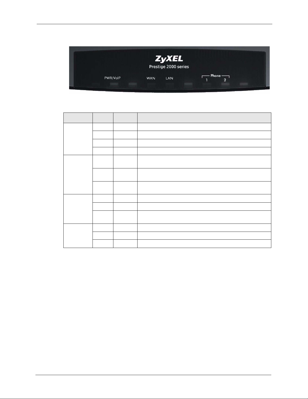
P-2302R Series User’s Guide
Figure 1 LEDs
Table 1 LED Descriptions
LED COLOR STATUS DESCRIPTION
PWR/VoIP Green On The Prestige is receiving power.
Blinking The Prestige is self-testing.
Orange On The VoIP SIP registration was successful.
Off The Prestige is not receiving power.
WAN Green On The Prestige has an Ethernet connection with the cable/DSL
Blinking The Prestige is sending/receiving data to /from the cable/DSL
Off The Prestige doesn’t have an Ethernet connection with the cable/
LAN Green On The Prestige has an Ethernet connection with a computer.
Blinking The Prestige is sending/receiving data to /from the computer.
Off The Prestige does not have an Ethernet connection with a
Phone 1-2 Green On The telephone(s) connected to this port is (are) in use.
Blinking The telephone(s) connected to this port is (are) ringing.
Off The telephone(s) connected to this port is (are) not in use.
modem.
modem.
DSL modem.
computer.
1.5 Applications
Here are some examples of how you can use your Prestige.
1.5.1 Make Calls via Internet Telephony Service Provider
In a home or small office environment, you can use the Prestige to make and receive VoIP
telephone calls through an Internet Telephony Service Provider (ITSP).
Chapter 1 Introducing the Prestige 40

P-2302R Series User’s Guide
The following figure shows a basic example of how you would make a VoIP call through an
ITSP. You use your analog phone (A in the figure) and the Prestige (B) changes the call into
VoIP. The Prestige then sends your call through your modem or router (C) to the Internet and
the ITSP’s SIP server (D). The VoIP call server forwards calls to PSTN phones (F) through a
trunking gateway (E) to the PSTN network. The VoIP call server forwards calls to IP phones
(G) through the Internet.
Figure 2 Internet Telephony Service Provider Application
1.5.2 Make Calls via IP-PBX
If your company has an IP-PBX (Internet Protocol Private Branch Exchange), you can use the
Prestige to make and receive VoIP telephone calls through it.
In this example, you use your analog phone (A in the figure) and the Prestige (B) changes the
call into VoIP and sends it to the IP-PBX. The IP-PBX forwards calls to PSTN phones (C) to
the PSTN network. The IP-PBX forwards calls to IP phones (D) through an IP network (this
could include the Internet).
41 Chapter 1 Introducing the Prestige
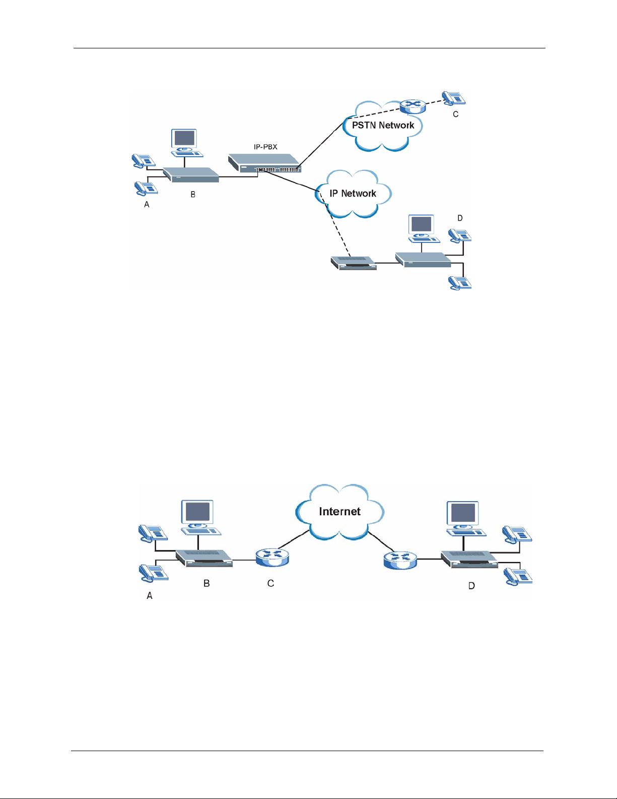
Figure 3 IP-PBX Application
1.5.3 Make Peer-to-peer Calls
P-2302R Series User’s Guide
Use the Prestige to make a call to the recipient’s IP address without using a SIP proxy server
Peer-to-peer calls are also called “Point to Point” or “IP-to-IP” calls. You must know the
peer’s IP address in order to do this.
The following figure shows a basic example of how you would make a peer-to-peer VoIP call.
You use your analog phone (A in the figure) and the Prestige (B) changes the call into VoIP.
The Prestige then sends your call through your modem or router (C) and the Internet to the
peer VoIP device (D).
Figure 4 Peer-to-peer Calling
Chapter 1 Introducing the Prestige 42

P-2302R Series User’s Guide
43 Chapter 1 Introducing the Prestige

Introducing the Web
This chapter describes how to access the Prestige web configurator and provides an overview
of its screens.
2.1 Web Configurator Overview
The web configurator is an HTML-based management interface that allows easy Prestige
setup and management via Internet browser. Use Internet Explorer 6.0 and later or Netscape
Navigator 7.0 and later versions. The recommended screen resolution is 1024 by 768 pixels.
P-2302R Series User’s Guide
CHAPTER 2
Configurator
In order to use the web configurator you need to allow:
• Web browser pop-up windows from your device. Web pop-up blocking is enabled by
default in Windows XP SP (Service Pack) 2.
• JavaScripts (enabled by default).
• Java permissions (enabled by default).
See the troubleshooting chapter if you want to make sure these functions are allowed in
Internet Explorer or Netscape Navigator.
2.2 Accessing the Prestige Web Configurator
1 Make sure your Prestige hardware is properly connected and prepare your computer/
computer network to connect to the Prestige (refer to Appendix C on page 344).
2 Launch your web browser.
3 Type "192.168.1.1" (the Prestige’s default LAN IP address) as the URL.
Figure 5 Web Site Address
4 Type "1234" (default) as the password and click Login. In some versions, the default
password appears automatically - if this is the case, click Login.
Chapter 2 Introducing the Web Configurator 44

P-2302R Series User’s Guide
Figure 6 Enter Password
5 You should see a screen asking you to change your password (highly recommended) as
shown next. Type a new password (and retype it to confirm) and click Apply or click
Ignore.
Figure 7 Change Password
6 You should now see the web configurator MAIN MENU screen (Figure 8 on page 47).
Note: The Prestige automatically logs you out if the management session is idle for
five minutes. Simply log back in if this happens to you.
2.3 Resetting the Prestige
If you forget your password or cannot access the web configurator, you will need to reload the
factory-default configuration file or use the RESET button the back of the Prestige. Uploading
this configuration file replaces the current configuration file with the factory-default
configuration file. This means that you will lose all configurations that you had previously.
The password will also be reset to “1234”.
2.3.1 Procedure To Use The Reset Button
Make sure the PWR/VoIP LED is on (not blinking) before you begin this procedure.
45 Chapter 2 Introducing the Web Configurator

P-2302R Series User’s Guide
1 Press the RESET button for five to ten seconds (release it when the PWR/VoIP LED
begins to blink). When the PWR/VoIP LED starts blinking, the defaults have been
restored and the Prestige restarts. Otherwise, go to step 2.
2
Disconnect and reconnect the Prestige’s power.
3 Wait for the PWR/VoIP LED to stop blinking and stay on steady.
4 Press the RESET button for five to ten seconds (release it when the PWR/VoIP LED
begins to blink). When the PWR/VoIP LED starts blinking, the defaults have been
restored and the Prestige restarts. Otherwise, go to step 2.
2.4 Navigating the Prestige Web Configurator
The following summarizes how to navigate the web configurator from the MAIN MENU
screen.
Note: Click the Help icon (located in the top right corner of most screens) to view
online help.
• Click WIZARD for initial configuration.
• Click a link under ADVANCED to configure Prestige features.
• Click MAINTENANCE to view information about your Prestige or upgrade
configuration/firmware files. Maintenance includes the Status, DHCP Ta bl e, F/W
(firmware) Upload, Configuration (Backup, Restore, Defaults) and Restart screens.
• Click LOGOUT at any time to exit the web configurator.
Chapter 2 Introducing the Web Configurator 46
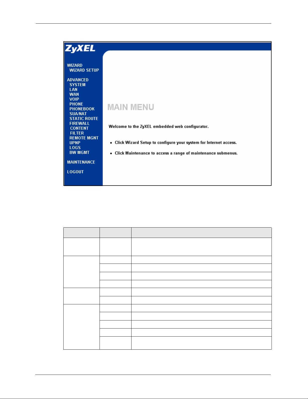
P-2302R Series User’s Guide
Figure 8 Web Configurator
The following table describes the sub-menus.
Table 2 Web Configurator Screens Summary
LINK TAB FUNCTION
WIZARD
SETUP
SYSTEM General Use this screen to configure general system settings.
DDNS Use this screen to set up dynamic DNS.
Password Use this screen to change your password.
Time Setting Use this screen to change your Prestige’s time and date.
LAN
WAN
IP Use this screen to configure LAN DHCP and TCP/IP settings.
IP Alias Use this screen to partition your LAN interface into subnets.
Route This screen allows you to configure route priority.
WAN ISP Use this screen to change your Prestige’s WAN ISP settings.
WAN IP Use this screen to change your Prestige’s WAN IP settings.
WAN MAC Use this screen to change your Prestige’s WAN MAC settings.
Traffic
Redirect
Use these screens for initial configuration including general setup,
ISP parameters for Internet Access, WAN IP/DNS Server/MAC
address assignment and VoIP.
Use this screen to configure your traffic redirect properties and
parameters.
47 Chapter 2 Introducing the Web Configurator

P-2302R Series User’s Guide
Table 2 Web Configurator Screens Summary (continued)
LINK TAB FUNCTION
VOIP VoIP Use this screen to configure your Prestige’s Voice over IP settings.
QoS Use this screen to configure your Prestige’s Quality of Service
PHONE Phone Port Use this screen to configure your Prestige’s phone settings.
Common Use this screen to configure general phone port settings.
PHONE BOOK Speed Dial Use this screen to configure speed dial for SIP phone numbers that
Lifeline Use this screen to configure your Prestige’s settings for PSTN calls
SUA/NAT SUA Server Use this screen to configure servers behind the Prestige.
Address
Mapping
Trigger Port Use this screen to change your Prestige’s trigger port settings.
STATIC ROUTE IP Static
Route
FIREWALL Settings Use this screen to activate/deactivate the firewall and log packets
Services Use this screen to enable service blocking (LAN to WAN firewall
CONTENT
FILTER
REMOTE
MGMT
UPnP
LOGS
BW MGMT Summary Use this screen to enable bandwidth management on an interface
Filter This screen allows you to block sites containing certain keywords in
TELNET Use this screen to configure through which interface(s) and from
FTP Use this screen to configure through which interface(s) and from
WWW Use this screen to configure through which interface(s) and from
SNMP Use this screen to configure your Prestige’s settings for Simple
DNS Use this screen to configure through which interface(s) and from
Security Use this screen to change your anti-probing settings.
UPnP Use this screen to enable UPnP on the Prestige.
View Log Use this screen to view the logs for the categories that you selected.
Log Settings Use this screen to change your Prestige’s log settings.
Class Setup Use this screen to define bandwidth classes.
Monitor Use this screen to view bandwidth class statistics.
settings.
you call often.
(Prestige 2302RL only).
Use this screen to configure network address translation mapping
rules.
Use this screen to configure IP static routes.
related to firewall rules.
rules).
the URL and set the days and times for the Prestige to perform
content filtering.
which IP address(es) users can use Telnet to manage the Prestige.
which IP address(es) users can use FTP to access the Prestige.
which IP address(es) users can use HTTP to manage the Prestige.
Network Management Protocol management.
which IP address(es) users can send DNS queries to the Prestige.
and set the maximum allowed bandwidth and scheduler for the
interface.
Chapter 2 Introducing the Web Configurator 48

P-2302R Series User’s Guide
Table 2 Web Configurator Screens Summary (continued)
LINK TAB FUNCTION
MAINTENANCE Status This screen contains administrative and system-related information.
DHCP Table This screen shows which network clients are using the DHCP server.
Any IP This screen lists the devices that are using the Any IP feature to
F/W Upload Use this screen to upload firmware to your Prestige
Configuration Use this screen to backup and restore the configuration or reset the
Restart This screen allows you to reboot the Prestige without turning the
LOGOUT Click this label to exit the web configurator.
communicate with the Prestige.
factory defaults to your Prestige.
power off.
2.5 Common Screen Command Buttons
The following table shows common command buttons found on many web configurator
screens.
Table 3 Common Screen Command Buttons
Apply Click Apply to save your changes back to the Prestige.
Reset/Cancel Click Reset or Cancel to begin configuring this screen afresh.
49 Chapter 2 Introducing the Web Configurator

This chapter provides information on the Wizard Setup screens in the web configurator.
3.1 Wizard Setup Overview
The web configurator’s setup wizard helps you configure your device to access the Internet
and make phone calls over the Internet. Leave a field blank if you don’t have information for
it.
Note: You should have a SIP account already set up.
P-2302R Series User’s Guide
CHAPTER 3
Wizard Setup
3.2 Wizard 1: General Setup
Note: This screen is optional. You can just click Next if you do not want to configure
it.
General Setup contains administrative and system-related information. System Name is for
identification purposes. However, because some ISPs check this name you should enter your
computer's "Computer Name". See Section 4.3 on page 62 for how to find your computer’s
computer name.
3.2.1 Domain Name
The Domain Name entry is what is propagated to the DHCP clients on the LAN. If you leave
this blank, the domain name obtained by DHCP from the ISP is used. While you must enter
the host name (System Name) on each individual computer, the domain name can be assigned
from the Prestige via DHCP.
Click Next to configure the Prestige for Internet access.
Chapter 3 Wizard Setup 50

P-2302R Series User’s Guide
Figure 9 Wizard 1: General Setup
3.3 Wizard 2: ISP Parameters for Internet Access
This screen varies depending on what encapsulation type you use. The Prestige offers
Ethernet and PPP over Ethernet encapsulation.
3.3.1 Ethernet
Choose Ethernet when the WAN port is used as a regular Ethernet.
For ISPs (such as Telstra) that send UDP heartbeat packets to verify that the customer is still
online, please create a WA N t o L AN firewall rule for those packets. Contact your ISP to find
the correct port number.
51 Chapter 3 Wizard Setup

Figure 10 Wizard 2: Ethernet Encapsulation
P-2302R Series User’s Guide
The following table describes the labels in this screen.
Table 4 Wizard 2: Ethernet Encapsulation
LABEL DESCRIPTION
ISP Parameters for Internet Access
Encapsulation You must choose the Ethernet option when the WAN port is used as a regular
Ethernet. Otherwise, choose PPP over Ethernet for a dial-up connection.
Service Type Choose from Standard, RR-Toshiba (Roadrunner Toshiba authentication
User Name Type the user name given to you by your ISP.
Password Type the password associated with the user name above.
Login Server IP
Address
Back Click Back to return to the previous screen.
Next Click Next to continue.
method), RR-Manager (Roadrunner Manager authentication method) or RR-
Telstr a (RoadRunner Telstra authentication method).
The following fields are not applicable (N/A) for the Standard service type.
Type the authentication server IP address here if your ISP gave you one.
3.3.2 PPPoE Encapsulation
Point-to-Point Protocol over Ethernet (PPPoE) functions as a dial-up connection. PPPoE is an
IETF (Internet Engineering Task Force) standard specifying how a host personal computer
interacts with a broadband modem (for example DSL, cable, wireless, etc.) to achieve access
to high-speed data networks.
Chapter 3 Wizard Setup 52

P-2302R Series User’s Guide
Figure 11 Wizard 2: PPPoE Encapsulation
The following table describes the labels in this screen.
Table 5 Wizard 2: PPPoE Encapsulation
LABEL DESCRIPTION
ISP Parameter for Internet Access
Encapsulation Choose PPP over Ethernet from the pull-down list box. PPPoE forms a dial-up
connection.
Service Name Type the name of your service provider.
User Name Type the user name given to you by your ISP.
Password Type the password associated with the user name above.
Nailed-Up
Connection
Idle Timeout Type the time in seconds that elapses before the router automatically disconnects
Back Click Back to return to the previous screen.
Next Click Next to continue.
Select Nailed-Up Connection if you do not want the connection to time out.
from the PPPoE server. The default time is 100 seconds.
53 Chapter 3 Wizard Setup
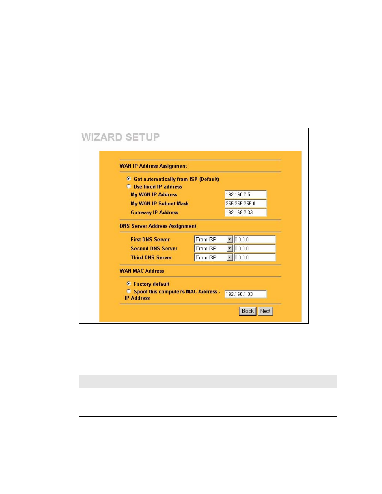
3.4 Wizard 3: WAN Setup
This wizard screen allows you to configure WAN IP address assignment, DNS server address
assignment and the WAN MAC address. See Chapter 6 on page 82 for background
information on these fields.
This wizard screen varies according to the type of encapsulation that you selected in the
previous wizard screen.
Figure 12 Wizard 3: WAN Setup
P-2302R Series User’s Guide
The following table describes the labels in this screen.
Table 6 Wizard 3: WAN Setup
LABEL DESCRIPTION
WAN IP Address
Assignment
Get automatically from
ISP (Default)
Use fixed IP address Select this option if the ISP assigned a fixed IP address.
Chapter 3 Wizard Setup 54
This section is available if you use Ethernet encapsulation with the
Standard service type or PPPoE encapsulation (in the previous screen).
This section is not available if you use Ethernet encapsulation with one of
the RoadRunner (RR-) service types.
Select this option if your ISP did not assign you a fixed IP address. This is
the default selection.

P-2302R Series User’s Guide
Table 6 Wizard 3: WAN Setup
LABEL DESCRIPTION
My WAN IP Address Enter your WAN IP address in this field if you selected Use Fixed IP
My WAN IP Subnet Mask
(Ethernet only)
Gateway IP Address
(Ethernet only)
My WAN IP Subnet Mask This field is available if you selected Ethernet encapsulation. Enter the IP
Gateway IP Address This field is available if you selected Ethernet encapsulation. Enter the
Remote IP Address This field is available if you selected PPPoE encapsulation. Enter the
Remote IP Subnet Mask This field is available if you selected PPPoE encapsulation. Enter the
DNS Server Address Assignment (if applicable)
DNS (Domain Name System) is for mapping a domain name to its corresponding IP address and vice
versa. The DNS server is extremely important because without it, you must know the IP address of a
computer before you can access it. The Prestige uses a system DNS server (in the order you specify
here) to resolve domain names for VPN, DDNS and the time server.
First DNS Server
Second DNS Server
Third DNS Server
WAN MAC Address The MAC address field allows you to configure the WAN port's MAC
Factory Default Select this option to use the factory assigned default MAC Address.
Spoof this Computer's
MAC address - IP Address
Back Click Back to return to the previous screen.
Next Click Next to continue.
Address.
Enter the IP subnet mask (if your ISP gave you one) in this field if you
selected Use Fixed IP Address.
Enter the gateway IP address of the neighboring device, if you know it. If
you do not, leave the field set to 0.0.0.0.
subnet mask (if your ISP gave you one) in this field if you selected Use
Fixed IP Address.
gateway IP address (if your ISP gave you one) in this field if you selected
Use Fixed IP Address.
remote IP Address (if your ISP gave you one) in this field.
remote IP Address (if your ISP gave you one) in this field.
Select From ISP if your ISP dynamically assigns DNS server information
(and the Prestige's WAN IP address). The field to the right displays the
(read-only) DNS server IP address that the ISP assigns.
Select User-Defined if you have the IP address of a DNS server. Enter the
DNS server's IP address in the field to the right.
Select None if you do not want to configure DNS servers. If you do not
configure a system DNS server, you must use IP addresses when
configuring VPN, DDNS and the time server.
address by either using the factory default or cloning the MAC address
from a computer on your LAN.
Select this option and enter the IP address of the computer on the LAN
whose MAC you are cloning. Once it is successfully configured, the
address will be copied to the rom file (ZyNOS configuration file). It will not
change unless you change the setting or upload a different rom file. It is
advisable to clone the MAC address from a computer on your LAN even if
your ISP does not presently require MAC address authentication.
55 Chapter 3 Wizard Setup

3.5 Wizard 4: SIP 1 Setup
This wizard screen allows you to configure your voice settings for SIP account 1. Fill in the
fields with information from your voice service provider. Leave the default settings in fields
for which no information was provided (except if otherwise specified). See Chapter 7 on page
90 for background information on these fields.
Note: This screen configures SIP account 1. Use the VoIP screens to configure SIP
account 2.
P-2302R Series User’s Guide
Chapter 3 Wizard Setup 56

P-2302R Series User’s Guide
Figure 13 Wizard 4: SIP 1 Setup
The following table describes the labels in this screen
Table 7 Wizard 4: SIP 1 Setup
LABEL DESCRIPTION
SIP Number Enter your SIP number in this field (use the number or text that comes
before the @ symbol in a SIP account like 1234@VoIP-provider.com
You can use up to 127 ASCII characters.
SIP Local Port Use this field to configure the Prestige’s listening port for SIP. Leave this
field set to the default if you were not given a local port number for SIP.
SIP Server Address Type the IP address or domain name of the SIP server in this field. It
doesn’t matter whether the SIP server is a proxy, redirect or register server.
You can use up to 95 ASCII characters.
SIP Server Port Enter the SIP server’s listening port for SIP in this field. Leave this field set
to the default if your VoIP service provider did not give you a server port
number for SIP.
57 Chapter 3 Wizard Setup
).

Table 7 Wizard 4: SIP 1 Setup
LABEL DESCRIPTION
P-2302R Series User’s Guide
REGISTER Server
Address
Enter the SIP register server’s IP address or domain name in this field. You
can use up to 95 ASCII characters.
Note: If you were not given a register server address, then
enter the address from the SIP Server Address field
again here.
REGISTER Server Port Enter the SIP register server’s listening port for SIP in this field.
Note: If you were not given a register server port, then enter
the port from the SIP Server Port field again here.
SIP Service Domain Enter the SIP service domain name in this field (the domain name that
Authentication User ID This is the user name for registering this SIP account with the SIP register
Authentication Password Type the password associated with the user name above. You can use up
Voice Compression Type Use this field to select the type of voice coder/decoder (codec) that you
NAT Passthrough Type Use STUN if there is a NAT router between the Prestige and the voice
Server Address Type the IP address or domain name of the STUN or outbound proxy
comes after the @ symbol in a SIP account like 1234@VoIP-
provider.com). You can use up to 127 ASCII Extended set characters.
server. Type the user name exactly as it was given to you. You can use up
to 95 ASCII characters.
to 95 ASCII Extended set characters.
want the Prestige to use. G.711 provides higher voice quality than G.729
but requires 64kbps of bandwidth while G.729 only requires 8kbps.
Select G.711>G.729 if you want the Prestige to first attempt to use the
G.711 codec and then the G.729 codec if the peer is not set up to use
G.711.
Select G.711 only if you want the Prestige to only use the G.711 codec
when making VoIP calls. You will not be able to connect to a peer that is
not set up to use G.711.
Select G.729>G.711 if you want the Prestige to first attempt to use the
G.729 codec and then the G.711 codec if the peer is not set up to use
G.729.
Select G.729 only if you want the Prestige to only use the G.729 codec
when making VoIP calls. You will not be able to connect to a peer that is
not set up to use G.729.
service provider’s SIP server. You do not need to use STUN if the NAT
router is also a SIP ALG.
Use Outbound Proxy if your VoIP service provider has a SIP outbound
server to handle voice calls. This allows the Prestige to work with any type
of NAT router and eliminates the need for STUN or a SIP ALG. Turn off a
SIP ALG on a NAT router in front of the Prestige to keep it from
retranslating the IP address (since this is already handled by the outbound
proxy server).
Use NONE if you were not given STUN or outbound proxy server
information.
server in this field. You can use up to 127 ASCII characters.
Ignore the Server Address/Port fields if you selected NONE for the NAT
Passthrough Type.
Chapter 3 Wizard Setup 58

P-2302R Series User’s Guide
Table 7 Wizard 4: SIP 1 Setup
LABEL DESCRIPTION
Server Port Enter the STUN or outbound proxy server’s listening port for STUN or
DTMF Mode The Dual-Tone Multi-Frequency (DTMF) mode sets how the Prestige
Country Code Use the drop-down list box to select the country where your Prestige is
Back Click Back to return to the previous screen.
Finish Click Finish to complete the wizard setup and save your configuration.
outbound proxy requests in this field. Leave this field set to the default if
your VoIP service provider did not give you a server port number for STUN
or outbound proxy.
handles the tones that your telephone makes when you push its buttons. It
is recommended that you use the same mode that your VoIP service
provider uses.
Select RFC 2833 to send the DTMF tones in RTP packets.
Select PCM (Pulse Code Modulation) to include the DTMF tones in the
voice data stream. This method works best when you are using a codec
that does not use compression (like G.711). Codecs that use compression
(like G.729) could distort the tones.
Select SIP INFO to send the DTMF tones in SIP messages.
located. Do not use Default.
3.6 Wizard Setup Complete
After you click Finish, the Prestige attempts to connect to the Internet and register your SIP
account. The PWR/VoIP LED turns orange after the SIP account registration is successful.
You can also click the hyper link in this screen to view the status of the Prestige’s WAN port
connection and SIP account registration.
59 Chapter 3 Wizard Setup

Figure 14 Wizard Finish
P-2302R Series User’s Guide
Well done! You have set up your Prestige to access the Internet and make VoIP calls.
Chapter 3 Wizard Setup 60

P-2302R Series User’s Guide
61 Chapter 3 Wizard Setup

This chapter provides information on the SYSTEM screens.
4.1 System Overview
This chapter describes how to configure the Prestige’s general, DDNS, password and time
settings.
4.2 DNS Overview
You can configure DNS (Domain Name System) setup in the following places.
P-2302R Series User’s Guide
CHAPTER 4
System Screens
1 Use the SYSTEM General screen to configure the Prestige to use a DNS server to
resolve domain names for Prestige system features like DDNS and the time server.
2 Use the LAN IP screen to configure the DNS server information that the Prestige sends
to the DHCP client devices on the LAN.
3 Use the Remote Management DNS screen to configure the Prestige to accept or discard
DNS queries.
4.3 General Screen
The General screen contains administrative and system-related information. System Name is
for identification purposes. However, because some ISPs check this name you should enter
your computer's "Computer Name".
• In Windows 95/98 click Start, Settings, Control Panel, Network. Click the
Identification tab, note the entry for the Computer Name field and enter it as the
System Name.
• In Windows 2000, click Start, Settings and Control Panel and then double-click
System. Click the Network Identification tab and then the Properties button. Note the
entry for the Computer name field and enter it as the System Name.
• In Windows XP, click Start, My Computer, View system information and then click
the Computer Name tab. Note the entry in the Full computer name field and enter it as
the Prestige System Name.
Chapter 4 System Screens 62

P-2302R Series User’s Guide
4.3.1 Domain Name
The Domain Name entry is what is propagated to the DHCP clients on the LAN. If you leave
this blank, the domain name obtained by DHCP from the ISP is used. While you must enter
the host name (System Name) on each individual computer, the domain name can be assigned
from the Prestige via DHCP.
4.3.2 DNS Server Address Assignment
Use DNS (Domain Name System) to map a domain name to its corresponding IP address and
vice versa, for instance, the IP address of www.zyxel.com is 204.217.0.2. The DNS server is
extremely important because without it, you must know the IP address of a computer before
you can access it.
The Prestige can get the DNS server addresses in the following ways.
1 The ISP tells you the DNS server addresses, usually in the form of an information sheet,
when you sign up. If your ISP gives you DNS server addresses, enter them in the DNS
Server fields in the SYSTEM General screen.
2 If the ISP did not give you DNS server information, leave the DNS Server fields in the
SYSTEM General screen set to 0.0.0.0 for the ISP to dynamically assign the DNS server
IP addresses.
4.4 System General Configuration
Click SYSTEM in the navigation panel and then General to display the following screen.
63 Chapter 4 System Screens

Figure 15 System General
P-2302R Series User’s Guide
The following table describes the labels in this screen.
Table 8 System General
LABEL DESCRIPTION
System Name This is for identification purposes. Enter your computer's "Computer Name". This
Domain Name The Domain Name entry is what is propagated to the DHCP clients on the LAN. If
Administrator
Inactivity Timer
System DNS
Servers
First DNS Server
Second DNS
Server
Third DNS Server
name can be up to 30 alphanumeric characters long. Spaces are not allowed, but
dashes “-” and underscores "_" are accepted.
you leave this blank, the domain name obtained by DHCP from the ISP is used.
Use up to 38 alphanumeric characters. Spaces are not allowed, but dashes “-” and
periods "." are accepted.
Type how many minutes a management session can be left idle before the session
times out. The default is 5 minutes. After it times out you have to log in with your
password again. Very long idle timeouts may have security risks. A value of "0"
means a management session never times out, no matter how long it has been left
idle (not recommended).
DNS (Domain Name System) is for mapping a domain name to its corresponding
IP address and vice versa, e.g., the IP address of www.zyxel.com is 204.217.0.2.
The DNS server is extremely important because without it, you must know the IP
address of a computer before you can access it.
Select From ISP if your ISP dynamically assigns DNS server information (and the
Prestige's WAN IP address). The field to the right displays the (read-only) DNS
server IP address that the ISP assigns.
Select User-Defined if you have the IP address of a DNS server. Enter the DNS
server's IP address in the field to the right.
Select None if you do not want to configure DNS servers. If you do not configure a
system DNS server, you must use IP addresses when configuring DDNS and the
time server.
Chapter 4 System Screens 64

P-2302R Series User’s Guide
Table 8 System General (continued)
LABEL DESCRIPTION
Apply Click Apply to save your changes back to the Prestige.
Reset Click Reset to begin configuring this screen afresh.
4.5 Dynamic DNS
Dynamic DNS allows you to update your current dynamic IP address with one or many
dynamic DNS services so that anyone can contact you (in NetMeeting, CU-SeeMe, etc.). You
can also access your FTP server or Web site on your own computer using a domain name (for
instance myhost.dhs.org, where myhost is a name of your choice) that will never change
instead of using an IP address that changes each time you reconnect. Your friends or relatives
will always be able to call you even if they don't know your IP address.
First of all, you need to have registered a dynamic DNS account with www.dyndns.org. This is
for people with a dynamic IP from their ISP or DHCP server that would still like to have a
domain name. The Dynamic DNS service provider will give you a password or key.
4.5.1 DynDNS Wildcard
Enabling the wildcard feature for your host causes *.yourhost.dyndns.org to be aliased to the
same IP address as yourhost.dyndns.org. This feature is useful if you want to be able to use,
for example, www.yourhost.dyndns.org and still reach your hostname.
Note: If you have a private WAN IP address, then you cannot use Dynamic DNS.
4.6 Configuring Dynamic DNS
To change your Prestige’s DDNS, click SYSTEM, then the DDNS tab. The screen appears as
shown.
65 Chapter 4 System Screens
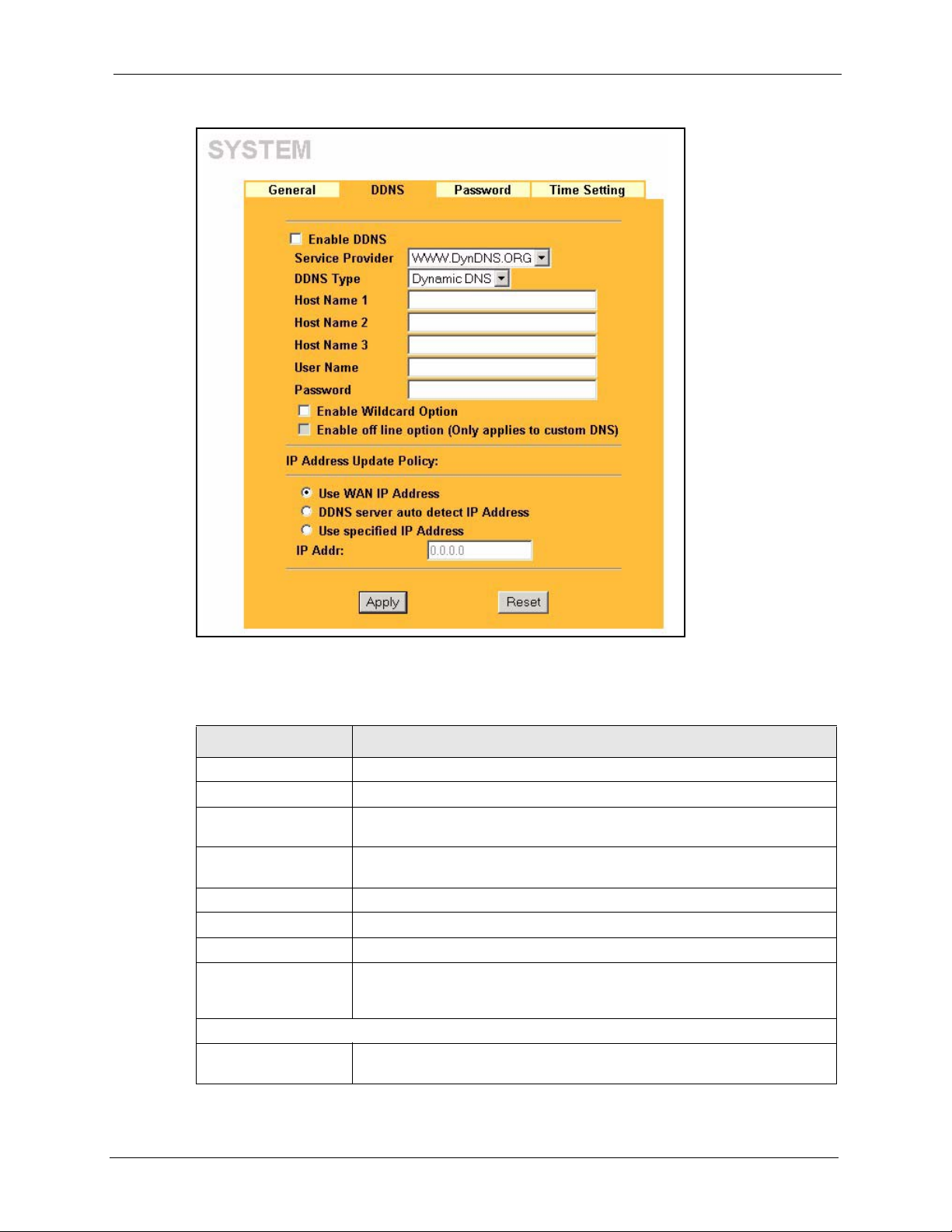
Figure 16 DDNS
P-2302R Series User’s Guide
The following table describes the labels in this screen.
Table 9 DDNS
LABEL DESCRIPTION
Enable DDNS Select this check box to use dynamic DNS.
Service Provider Select the name of your Dynamic DNS service provider.
DDNS Type Select the type of service that you are registered for from your Dynamic DNS
service provider.
Host Names 1~3 Enter the host names in the three fields provided. You can specify up to two
User Name Enter your user name.
Password Enter the password assigned to you.
Enable Wildcard Option Select the check box to enable DynDNS Wildcard.
Enable off line option
(Only applies to custom
DNS)
IP Address Update Policy:
Use WAN IP Address Select this option to have the Prestige update the domain name with the
host names in each field separated by a comma (",").
This option is available when CustomDNS is selected in the DDNS Type
field. Check with your Dynamic DNS service provider to have traffic
redirected to a URL (that you can specify) while you are off line.
WAN port's IP address.
Chapter 4 System Screens 66

P-2302R Series User’s Guide
Table 9 DDNS
LABEL DESCRIPTION
DDNS server auto
detect IP Address
Select this option to update the IP address of the host name(s) automatically
by the DDNS server. It is recommended that you select this option.
Select this option only when there are one or more NAT routers between the
Prestige and the DDNS server. This feature has the DDNS server
automatically detect and use the IP address of the NAT router that has a
public IP address.
Note: The DDNS server may not be able to detect the proper
IP address if there is an HTTP proxy server between the
Prestige and the DDNS server.
Use specified IP
Address
IP Addr: Enter the IP address if you select the User Specify option.
Apply Click Apply to save your changes back to the Prestige.
Reset Click Reset to begin configuring this screen afresh.
Select this option to update the IP address of the host name(s) to the IP
address specified below. Use this option if you have a static IP address.
4.7 Configuring Password
To change your Prestige’s password (recommended), click SYSTEM in the navigation panel,
and then the Password tab. The screen appears as shown.
Figure 17 Password
The following table describes the labels in this screen.
Table 10 Password
LABEL DESCRIPTION
Old Password Type the default password or the existing password you use to access the
system in this field.
New Password Type the new password in this field (up to 30 characters). Note that as you type
a password, the screen displays an asterisk (*) for each character you type.
67 Chapter 4 System Screens

Table 10 Password (continued)
LABEL DESCRIPTION
Retype to Confirm Type the new password again in this field.
Apply Click Apply to save your changes back to the Prestige.
Reset Click Reset to begin configuring this screen afresh.
4.8 Pre-defined NTP Time Servers List
The Prestige uses the following pre-defined list of NTP time servers if you do not specify a
time server or it cannot synchronize with the time server you specified.
Note: The Prestige can use this pre-defined list of time servers regardless of the Time
Protocol you select.
When the Prestige uses the pre-defined list of NTP time servers, it randomly selects one server
and tries to synchronize with it. If the synchronization fails, then the Prestige goes through the
rest of the list in order from the first one tried until either it is successful or all the pre-defined
NTP time servers have been tried.
P-2302R Series User’s Guide
Table 11 Pre-defined NTP Time Servers
ntp1.cs.wisc.edu
ntp1.gbg.netnod.se
ntp2.cs.wisc.edu
tock.usno.navy.mil
ntp3.cs.wisc.edu
ntp.cs.strath.ac.uk
ntp1.sp.se
time1.stupi.se
tick.stdtime.gov.tw
tock.stdtime.gov.tw
time.stdtime.gov.tw
4.9 Configuring Time Setting
To change your Prestige’s time and date, click SYSTEM in the navigation panel, then the
Time Setting tab. The screen appears as shown. Use this screen to configure the Prestige’s
time based on your local time zone.
Chapter 4 System Screens 68
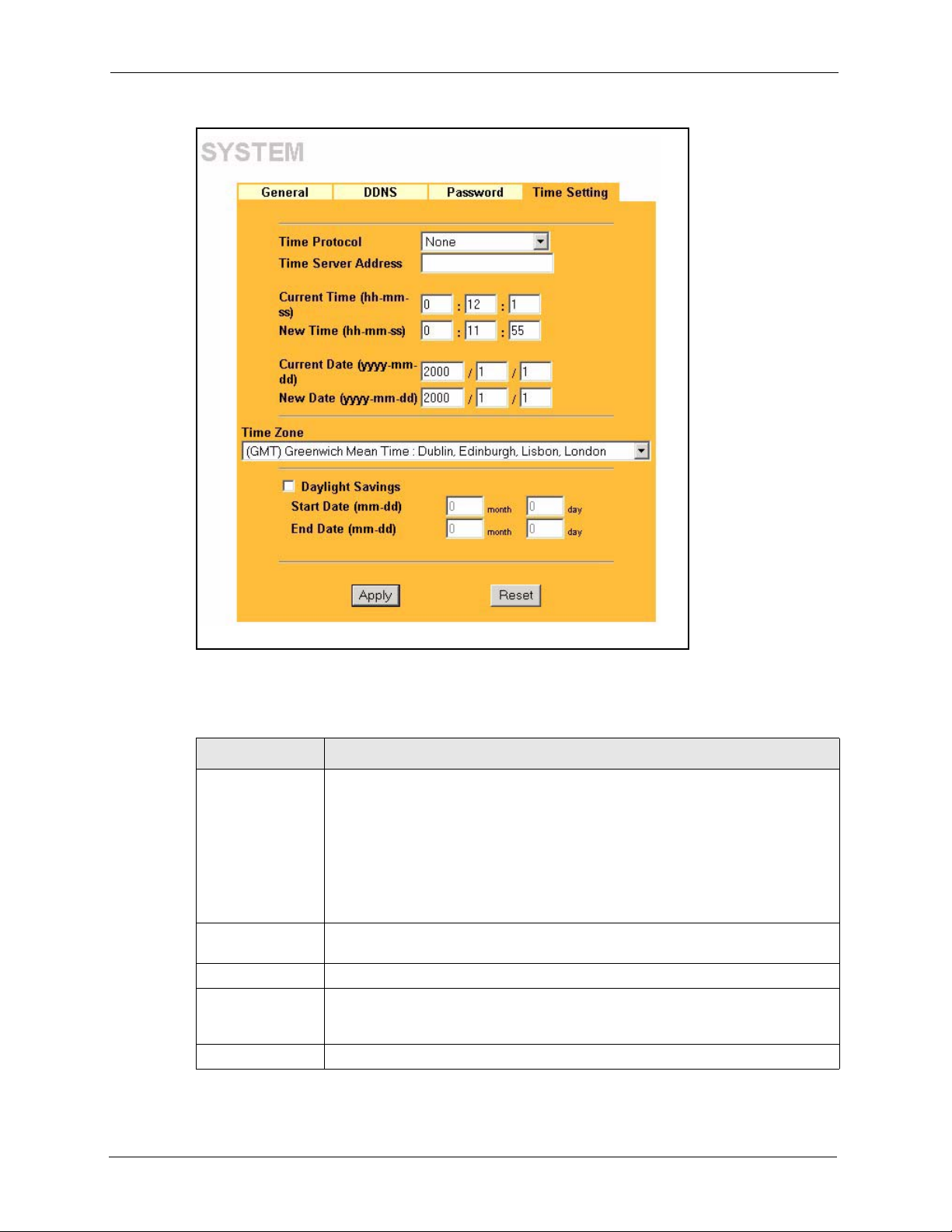
P-2302R Series User’s Guide
Figure 18 Time Setting
The following table describes the labels in this screen.
Table 12 Time Setting
LABEL DESCRIPTION
Time Protocol Select the time service protocol that your time server uses. Not all time servers
support all protocols, so you may have to check with your ISP/network
administrator or use trial and error to find a protocol that works.
The main difference between them is the format.
Daytime (RFC 867) format is day/month/year/time zone of the server.
Time (RFC 868) format displays a 4-byte integer giving the total number of
seconds since 1970/1/1 at 0:0:0.
The default, NTP (RFC 1305), is similar to Time (RFC 868).
Select None to enter the time and date manually.
Time Server
Address
Current Time This field displays the Prestige’s present time.
New Time This field displays the last updated time from the time server.
Current Date This field displays the Prestige’s present date.
Enter the IP address or URL of your time server. Check with your ISP or network
administrator if you are unsure of this information.
When you select None in the Time Protocol field, enter the new time in this field
and then click Apply.
69 Chapter 4 System Screens

Table 12 Time Setting (continued)
LABEL DESCRIPTION
New Date This field displays the last updated date from the time server.
When you select None in the Time Protocol field, enter the new date in this field
and then click Apply.
Time Zone Choose the Time Zone of your location. This will set the time difference between
your time zone and Greenwich Mean Time (GMT).
Daylight Savings Select this option if you use daylight savings time. Daylight saving is a period from
late spring to early fall when many countries set their clocks ahead of normal local
time by one hour to give more daytime light in the evening.
Start Date Enter the month and day that your daylight-savings time starts on if you selected
Daylight Savings.
End Date Enter the month and day that your daylight-savings time ends on if you selected
Daylight Savings.
Apply Click Apply to save your changes back to the Prestige.
Reset Click Reset to begin configuring this screen afresh.
4.9.1 Resetting the Time
P-2302R Series User’s Guide
The Prestige resets the time in the following instances:
• On saving your changes.
• When the Prestige starts up.
• 24-hour intervals after starting.
Chapter 4 System Screens 70

P-2302R Series User’s Guide
71 Chapter 4 System Screens

5.1 LAN Overview
A Local Area Network (LAN) is a shared communication system to which many computers
are attached. A LAN is a computer network limited to the immediate area, usually the same
building or floor of a building. The LAN screens can help you configure a LAN DHCP server,
manage IP addresses, and partition your physical network into logical networks.
P-2302R Series User’s Guide
CHAPTER 5
LAN Setup
This chapter describes how to configure LAN settings.
5.2 IP Address and Subnet Mask
Similar to the way houses on a street share a common street name, so too do computers on a
LAN share one common network number.
Where you obtain your network number depends on your particular situation. If the ISP or
your network administrator assigns you a block of registered IP addresses, follow their
instructions in selecting the IP addresses and the subnet mask.
If the ISP did not explicitly give you an IP network number, then most likely you have a single
user account and the ISP will assign you a dynamic IP address when the connection is
established. If this is the case, it is recommended that you select a network number from
192.168.0.0 to 192.168.255.0 and you must enable the Network Address Translation (NAT)
feature of the Prestige. The Internet Assigned Number Authority (IANA) reserved this block
of addresses specifically for private use; please do not use any other number unless you are
told otherwise. Let's say you select 192.168.1.0 as the network number; which covers 254
individual addresses, from 192.168.1.1 to 192.168.1.254 (zero and 255 are reserved). In other
words, the first three numbers specify the network number while the last number identifies an
individual computer on that network.
Once you have decided on the network number, pick an IP address that is easy to remember,
for instance, 192.168.1.1, for your Prestige, but make sure that no other device on your
network is using that IP address.
The subnet mask specifies the network number portion of an IP address. Your Prestige will
compute the subnet mask automatically based on the IP address that you entered. You don't
need to change the subnet mask computed by the Prestige unless you are instructed to do
otherwise.
Chapter 5 LAN Setup 72

P-2302R Series User’s Guide
5.3 DHCP Setup
DHCP (Dynamic Host Configuration Protocol, RFC 2131 and RFC 2132) allows individual
clients to obtain TCP/IP configuration at start-up from a server. You can configure the Prestige
as a DHCP server or disable it. When configured as a server, the Prestige provides the TCP/IP
configuration for the clients. If DHCP service is disabled, you must have another DHCP server
on your LAN, or else the computer must be manually configured.
5.3.1 IP Pool Setup
The Prestige is pre-configured with a pool of IP addresses for the DHCP clients (DHCP Pool).
See the product specifications in the appendices. Do not assign static IP addresses from the
DHCP pool to your LAN computers.
These parameters should work for the majority of installations. If your ISP gives you explicit
DNS server address(es), read the embedded web configurator help regarding what fields need
to be configured.
5.4 LAN TCP/IP
The Prestige has built-in DHCP server capability that assigns IP addresses and DNS servers to
systems that support DHCP client capability.
5.4.1 Factory LAN Defaults
The LAN parameters of the Prestige are preset in the factory with the following values:
• IP address of 192.168.1.1 with subnet mask of 255.255.255.0 (24 bits)
• DHCP server enabled with 32 client IP addresses starting from 192.168.1.33.
These parameters should work for the majority of installations. If your ISP gives you explicit
DNS server address(es), read the embedded web configurator help regarding what fields need
to be configured.
5.5 DNS Server Address
DNS (Domain Name System) is for mapping a domain name to its corresponding IP address
and vice versa. The DNS server is extremely important because without it, you must know the
IP address of a machine before you can access it. The DNS server addresses that you enter in
the DHCP setup are passed to the client machines along with the assigned IP address and
subnet mask.
73 Chapter 5 LAN Setup

P-2302R Series User’s Guide
There are two ways that an ISP disseminates the DNS server addresses. The first is for an ISP
to tell a customer the DNS server addresses, usually in the form of an information sheet, when
s/he signs up. If your ISP gives you the DNS server addresses, enter them in the DNS Server
fields in DHCP Setup, otherwise, leave them blank.
Some ISPs choose to pass the DNS servers using the DNS server extensions of PPP IPCP (IP
Control Protocol) after the connection is up. If your ISP did not give you explicit DNS
servers, chances are the DNS servers are conveyed through IPCP negotiation. The Prestige
supports the IPCP DNS server extensions through the DNS proxy feature.
If the Primary and Secondary DNS Server fields in the LAN Setup screen are not specified,
for instance, left as 0.0.0.0, the Prestige tells the DHCP clients that it itself is the DNS server.
When a computer sends a DNS query to the Prestige, the Prestige forwards the query to the
real DNS server learned through IPCP and relays the response back to the computer.
Please note that DNS proxy works only when the ISP uses the IPCP DNS server extensions. It
does not mean you can leave the DNS servers out of the DHCP setup under all circumstances.
If your ISP gives you explicit DNS servers, make sure that you enter their IP addresses in the
LAN Setup screen. This way, the Prestige can pass the DNS servers to the computers and the
computers can query the DNS server directly without the Prestige’s intervention.
5.6 RIP Setup
RIP (Routing Information Protocol) allows a router to exchange routing information with
other routers. The RIP Direction field controls the sending and receiving of RIP packets.
When set to:
• Both - the Prestige will broadcast its routing table periodically and incorporate the RIP
information that it receives.
• In Only - the Prestige will not send any RIP packets but will accept all RIP packets
received.
• Out Only - the Prestige will send out RIP packets but will not accept any RIP packets
received.
• None - the Prestige will not send any RIP packets and will ignore any RIP packets
received.
The Version field controls the format and the broadcasting method of the RIP packets that the
Prestige sends (it recognizes both formats when receiving). RIP-1 is universally supported;
but RIP-2 carries more information. RIP-1 is probably adequate for most networks, unless
you have an unusual network topology.
Both RIP-2B and RIP-2M sends the routing data in RIP-2 format; the difference being that
RIP-2B uses subnet broadcasting while RIP-2M uses multicasting.
Chapter 5 LAN Setup 74

P-2302R Series User’s Guide
5.7 Multicast
Traditionally, IP packets are transmitted in one of either two ways - Unicast (1 sender - 1
recipient) or Broadcast (1 sender - everybody on the network). Multicast delivers IP packets to
a group of hosts on the network - not everybody and not just 1.
IGMP (Internet Group Multicast Protocol) is a network-layer protocol used to establish
membership in a Multicast group - it is not used to carry user data. IGMP version 2 (RFC
2236) is an improvement over version 1 (RFC 1112) but IGMP version 1 is still in wide use. If
you would like to read more detailed information about interoperability between IGMP
version 2 and version 1, please see sections 4 and 5 of RFC 2236. The class D IP address is
used to identify host groups and can be in the range 224.0.0.0 to 239.255.255.255. The address
224.0.0.0 is not assigned to any group and is used by IP multicast computers. The address
224.0.0.1 is used for query messages and is assigned to the permanent group of all IP hosts
(including gateways). All hosts must join the 224.0.0.1 group in order to participate in IGMP.
The address 224.0.0.2 is assigned to the multicast routers group.
The Prestige supports both IGMP version 1 (IGMP-v1) and IGMP version 2 (IGMP-v2). At
start up, the Prestige queries all directly connected networks to gather group membership.
After that, the Prestige periodically updates this information. IP multicasting can be enabled/
disabled on the Prestige LAN and/or WAN interfaces in the web configurator (LAN; WA N ).
Select None to disable IP multicasting on these interfaces.
5.8 Any IP
Traditionally, you must set the IP addresses and the subnet masks of a computer and the
Prestige to be in the same subnet to allow the computer to access the Internet (through the
Prestige). In cases where your computer is required to use a static IP address in another
network, you may need to manually configure the network settings of the computer every time
you want to access the Internet via the Prestige.
With the Any IP feature and NAT enabled, the Prestige allows a computer to access the
Internet without changing the network settings (such as IP address and subnet mask) of the
computer, when the IP addresses of the computer and the Prestige are not in the same subnet.
Whether a computer is set to use a dynamic or static (fixed) IP address, you can simply
connect the computer to the Prestige and access the Internet.
The following figure depicts a scenario where a computer is set to use a static private IP
address in the corporate environment. In a residential house where a Prestige is installed, you
can still use the computer to access the Internet without changing the network settings, even
when the IP addresses of the computer and the Prestige are not in the same subnet.
75 Chapter 5 LAN Setup

Figure 19 Any IP Example
P-2302R Series User’s Guide
The Any IP feature does not apply to a computer using either a dynamic IP address or a static
IP address that is in the same subnet as the Prestige’s IP address.
Note: You must enable NAT/SUA to use the Any IP feature on the Prestige.
5.8.0.1 How Any IP Works
Address Resolution Protocol (ARP) is a protocol for mapping an Internet Protocol address (IP
address) to a physical machine address, also known as a Media Access Control or MAC
address, on the local area network. IP routing table is defined on IP Ethernet devices (the
Prestige) to decide which hop to use,
The following lists out the steps taken, when a computer tries to access the Internet for the first
time through the Prestige.
1 When a computer (which is in a different subnet) first attempts to access the Internet, it
sends packets to its default gateway (which is not the Prestige) by looking at the MAC
address in its ARP table.
2 When the computer cannot locate the default gateway, an ARP request is broadcast on the
LAN.
3 The Prestige receives the ARP request and replies to the computer with its own MAC
address.
to help forward data along to its specified destination.
4 The computer updates the MAC address for the default gateway to the ARP table. Once
the ARP table is updated, the computer is able to access the Internet through the Prestige.
5 When the Prestige receives packets from the computer, it creates an entry in the IP
routing table so it can properly forward packets intended for the computer.
Chapter 5 LAN Setup 76

P-2302R Series User’s Guide
After all the routing information is updated, the computer can access the Prestige and the
Internet as if it is in the same subnet as the Prestige.
5.9 Configuring LAN
Click LAN and IP to open the following screen.
Figure 20 LAN IP
The following table describes the fields in this screen.
77 Chapter 5 LAN Setup

P-2302R Series User’s Guide
Table 13 LAN IP
LABEL DESCRIPTION
DHCP
DHCP Server Enable the DHCP server to have the Prestige assign IP addresses, an IP default
gateway and DNS servers to Windows 95, Windows NT and other systems that
support the DHCP client.
When DHCP is used, the following items need to be set:
IP Pool Starting
Address
Pool Size This field specifies the size or count of the IP address pool.
DNS Servers Assigned by DHCP Server
The Prestige passes a DNS (Domain Name System) server IP address (in the order you specify here)
to the DHCP clients. The Prestige only passes this information to the LAN DHCP clients when you
select the DHCP Server check box. When you clear the DHCP Server check box, DHCP service is
disabled and you must have another DHCP sever on your LAN, or else the computers must have their
DNS server addresses manually configured.
First DNS Server
Second DNS Server
Third DNS Server
TCP/IP
IP Address Enter the IP address of your Prestige in dotted decimal notation, for example,
IP Subnet Mask The subnet mask specifies the network number portion of an IP address. Your
Multicast IGMP (Internet Group Multicast Protocol) is a network-layer protocol used to
RIP Direction Select the RIP direction from None, Both, In Only and Out Only.
RIP Version Select the RIP version from RIP-1, RIP-2B and RIP-2M.
Multicast IGMP (Internet Group Multicast Protocol) is a network-layer protocol used to
This field specifies the first of the contiguous addresses in the IP address pool.
Select From ISP if your ISP dynamically assigns DNS server information (and
the Prestige's WAN IP address). The field to the right displays the (read-only)
DNS server IP address that the ISP assigns.
Select User-Defined if you have the IP address of a DNS server. Enter the DNS
server's IP address in the field to the right. If you chose User-Defined, but leave
the IP address set to 0.0.0.0, User-Defined changes to None after you click
Apply. If you set a second choice to User-Defined, and enter the same IP
address, the second User-Defined changes to None after you click Apply.
Select DNS Relay to have the Prestige act as a DNS proxy. The Prestige's LAN
IP address displays in the field to the right (read-only). The Prestige tells the
DHCP clients on the LAN that the Prestige itself is the DNS server. When a
computer on the LAN sends a DNS query to the Prestige, the Prestige forwards
the query to the Prestige's system DNS server (configured in the SYSTEM
General screen) and relays the response back to the computer. You can only
select DNS Relay for one of the three servers; if you select DNS Relay for a
second or third DNS server, that choice changes to None after you click Apply.
Select None if you do not want to configure DNS servers. If you do not configure
a DNS server, you must know the IP address of a computer in order to access it.
192.168.1.1 (factory default).
Prestige automatically calculates the subnet mask based on the IP address that
you assign. Unless you are implementing subnetting, use the subnet mask
computed by the Prestige.
establish membership in a multicast group. The Prestige supports both IGMP
version 1 (IGMP-v1) and IGMP-v2. Select None to disable it.
establish membership in a multicast group. The Prestige supports both IGMP
version 1 (IGMP-v1) and IGMP-v2. Select None to disable it.
Chapter 5 LAN Setup 78

P-2302R Series User’s Guide
Table 13 LAN IP (continued)
LABEL DESCRIPTION
Any IP Setup Select the Active check box to enable the Any IP feature. This allows a computer
to access the Internet without changing the network settings (such as IP address
and subnet mask) of the computer, even when the IP addresses of the computer
and the Prestige are not in the same subnet.
When you disable the Any IP feature, only computers with dynamic IP addresses
or static IP addresses in the same subnet as the Prestige’s LAN IP address can
connect to the Prestige or access the Internet through the Prestige.
Apply Click Apply to save your changes back to the Prestige.
Reset Click Reset to begin configuring this screen afresh.
5.10 Configuring IP Alias
IP alias allows you to partition a physical network into different logical networks over the
same Ethernet interface. The Prestige supports three logical LAN interfaces via its single
physical Ethernet interface with the Prestige itself as the gateway for each LAN network.
Note: Make sure that the subnets of the logical networks do not overlap.
The following figure shows a LAN divided into subnets A, B, and C.
Figure 21 Physical Network & Partitioned Logical Networks
To change your Prestige’s IP alias settings, click LAN, then the IP Alias tab. The screen
appears as shown.
79 Chapter 5 LAN Setup
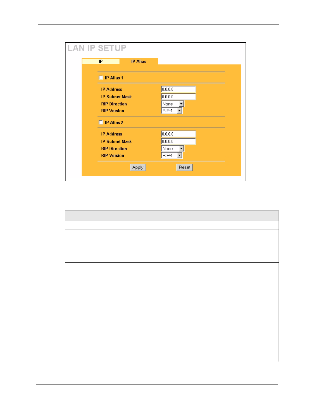
Figure 22 LAN IP Alias
P-2302R Series User’s Guide
The following table describes the labels in this screen.
Table 14 LAN IP Alias
LABEL DESCRIPTION
IP Alias 1, 2 Select the check box to configure another LAN network for the Prestige.
IP Address Enter the IP address of your Prestige' in dotted decimal notation.
Alternatively, click the right mouse button to copy and/or paste the IP address.
IP Subnet Mask Your Prestige will automatically calculate the subnet mask based on the IP
RIP Direction RIP (Routing Information Protocol, RFC1058 and RFC 1389) allows a router to
RIP Version The RIP Version field controls the format and the broadcasting method of the RIP
address that you assign. Unless you are implementing subnetting, use the subnet
mask computed by the Prestige.
exchange routing information with other routers. The RIP Direction field controls
the sending and receiving of RIP packets. Select the RIP direction from Both/In
Only/Out Only/None. When set to Both or Out Only, the Prestige will broadcast
its routing table periodically. When set to Both or In Only, it will incorporate the
RIP information that it receives; when set to None, it will not send any RIP packets
and will ignore any RIP packets received.
packets that the Prestige sends (it recognizes both formats when receiving). RIP-1
is universally supported but RIP-2 carries more information. RIP-1 is probably
adequate for most networks, unless you have an unusual network topology. Both
RIP-2B and RIP-2M sends the routing data in RIP-2 format; the difference being
that RIP-2B uses subnet broadcasting while RIP-2M uses multicasting.
Multicasting can reduce the load on non-router machines since they generally do
not listen to the RIP multicast address and so will not receive the RIP packets.
However, if one router uses multicasting, then all routers on your network must
use multicasting, also. By default, RIP direction is set to Both and the Version set
to RIP-1.
Chapter 5 LAN Setup 80

P-2302R Series User’s Guide
Table 14 LAN IP Alias
LABEL DESCRIPTION
Apply Click Apply to save your changes back to the Prestige.
Reset Click Reset to begin configuring this screen afresh.
81 Chapter 5 LAN Setup

This chapter describes how to configure WAN settings.
6.1 WAN Overview
Use this chapter to configure the settings for your WAN connection.
6.2 Configuring ISP
To change your Prestige’s WAN ISP settings, click WA N , then the ISP tab. The screen differs
by the encapsulation.
P-2302R Series User’s Guide
CHAPTER 6
WAN Screens
6.2.1 Ethernet Encapsulation
The screen shown next is for Ethernet encapsulation.
Chapter 6 WAN Screens 82

P-2302R Series User’s Guide
Figure 23 Ethernet Encapsulation
The following table describes the labels in this screen.
Table 15 Ethernet Encapsulation
LABEL DESCRIPTION
Encapsulation You must choose the Ethernet option when the WAN port is used as a regular
Ethernet.
Service Type Choose from Standard, RR-Toshiba (Roadrunner Toshiba authentication
User Name This field is not available if you select the Standard service type. Type the user
Password This field is not available if you select the Standard service type. Type the
Retype to Confirm This field is not available if you select the Standard service type. Type the
Login Server IP
Address
Apply Click Apply to save your changes back to the Prestige.
Reset Click Reset to begin configuring this screen afresh.
method), RR-Manager (Roadrunner Manager authentication method) or RR-
Tel str a (RoadRunner Telstra authentication method).
name given to you by your ISP.
password associated with the user name above.
password again to make sure that you have entered it correctly.
This field is not available if you select the Standard service type. Type the
authentication server IP address here if your ISP gave you one.
6.2.2 PPPoE Encapsulation
The Prestige supports PPPoE (Point-to-Point Protocol over Ethernet). PPPoE is an IETF
standard (RFC 2516) specifying how a personal computer (PC) interacts with a broadband
modem (DSL, cable, wireless, etc.) connection. The PPP over Ethernet option is for a dialup connection using PPPoE.
83 Chapter 6 WAN Screens

P-2302R Series User’s Guide
For the service provider, PPPoE offers an access and authentication method that works with
existing access control systems (for example Radius).
One of the benefits of PPPoE is the ability to let you access one of multiple network services,
a function known as dynamic service selection. This enables the service provider to easily
create and offer new IP services for individuals.
Operationally, PPPoE saves significant effort for both you and the ISP or carrier, as it requires
no specific configuration of the broadband modem at the customer site.
By implementing PPPoE directly on the Prestige (rather than individual computers), the
computers on the LAN do not need PPPoE software installed, since the Prestige does that part
of the task. Furthermore, with NAT, all of the LANs’ computers will have access.
The screen shown next is for PPPoE encapsulation.
Figure 24 PPPoE Encapsulation
The following table describes the labels in this screen.
Table 16 PPPoE Encapsulation
LABEL DESCRIPTION
ISP Parameters for Internet Access
Encapsulation The PPP over Ethernet choice is for a dial-up connection using PPPoE. The
Chapter 6 WAN Screens 84
Prestige supports PPPoE (Point-to-Point Protocol over Ethernet). PPPoE is an
IETF standard (RFC 2516) specifying how a personal computer (PC) interacts with
a broadband modem (for example DSL, cable, wireless, etc.) connection.
Operationally, PPPoE saves significant effort for both the end user and ISP/carrier,
as it requires no specific configuration of the broadband modem at the customer
site. By implementing PPPoE directly on the router rather than individual
computers, the computers on the LAN do not need PPPoE software installed, since
the router does that part of the task. Further, with NAT, all of the LAN's computers
will have access.

P-2302R Series User’s Guide
Table 16 PPPoE Encapsulation
LABEL DESCRIPTION
Service Name Type the PPPoE service name provided to you. PPPoE uses a service name to
identify and reach the PPPoE server.
User Name Type the user name given to you by your ISP.
Password Type the password associated with the User Name above.
Retype to Confirm Type your password again to make sure that you have entered is correctly.
Nailed-Up
Connection
Idle Timeout This value specifies the time in seconds that elapses before the router automatically
Apply Click Apply to save your changes back to the Prestige.
Reset Click Reset to begin configuring this screen afresh.
Select Nailed-Up Connection if you do not want the connection to time out.
disconnects from the PPPoE server.
6.3 WAN IP Address Assignment
Every computer on the Internet must have a unique IP address. If your networks are isolated
from the Internet, for instance, only between your two branch offices, you can assign any IP
addresses to the hosts without problems. However, the Internet Assigned Numbers Authority
(IANA) has reserved the following three blocks of IP addresses specifically for private
networks.
Table 17 Private IP Address Ranges
10.0.0.0 - 10.255.255.255
172.16.0.0 - 172.31.255.255
192.168.0.0 - 192.168.255.255
You can obtain your IP address from the IANA, from an ISP or have it assigned by a private
network. If you belong to a small organization and your Internet access is through an ISP, the
ISP can provide you with the Internet addresses for your local networks. On the other hand, if
you are part of a much larger organization, you should consult your network administrator for
the appropriate IP addresses.
Note: Regardless of your particular situation, do not create an arbitrary IP address;
always follow the guidelines above. For more information on address
assignment, please refer to RFC 1597, Address Allocation for Private Internets
and RFC 1466, Guidelines for Management of IP Address Space.
6.4 Configuring WAN IP
To change your Prestige’s WAN IP settings, click WAN , then the WAN I P tab. This screen
varies according to the type of encapsulation you select.
85 Chapter 6 WAN Screens

P-2302R Series User’s Guide
If your ISP did not assign you a fixed IP address, click Get automatically from ISP
(Default); otherwise click Use fixed IP Address and enter the IP address in the field provided.
Figure 25 WAN: IP
The following table describes the labels in this screen.
Table 18 WAN: IP
LABEL DESCRIPTION
WAN IP Address
Assignment
Get automatically from
ISP (Default)
Use fixed IP address Select this option if the ISP assigned a fixed IP address.
My WAN IP Address Enter your WAN IP address in this field if you selected Use Fixed IP Address.
My WAN IP Subnet
Mask
Gateway IP Address This field is available if you selected Ethernet encapsulation. Enter the
Chapter 6 WAN Screens 86
This section is available if you use Ethernet encapsulation with the Standard
service type or PPPoE encapsulation. This section is not available if you use
Ethernet encapsulation with one of the RoadRunner (RR-) service types.
Select this option if your ISP did not assign you a fixed IP address. This is the
default selection.
This field is available if you selected Ethernet encapsulation. Enter the IP
subnet mask (if your ISP gave you one) in this field if you selected Use Fixed
IP Address.
gateway IP address (if your ISP gave you one) in this field if you selected Use
Fixed IP Address.

P-2302R Series User’s Guide
Table 18 WAN: IP
LABEL DESCRIPTION
Remote IP Address This field is available if you selected PPPoE encapsulation. Enter the remote
Remote IP Subnet
Mask
Network Address
Translation
Metric This field is available if you selected PPPoE encapsulation. It sets this route's
Private This field is available if you selected PPPoE encapsulation. It determines if the
RIP Direction RIP (Routing Information Protocol) allows a router to exchange routing
IP Address (if your ISP gave you one) in this field.
This field is available if you selected PPPoE encapsulation. Enter the remote
IP Address (if your ISP gave you one) in this field.
Network Address Translation (NAT) allows the translation of an Internet
protocol address used within one network (for example a private IP address
used in a local network) to a different IP address known within another network
(for example a public IP address used on the Internet).
Choose None to disable NAT.
Choose SUA Only if you have a single public IP address. SUA (Single User
Account) is a subset of NAT that supports two types of mapping: Many-to-One
and Server.
Choose Full Feature if you have multiple public IP addresses. Full Feature
mapping types include: One-to-One, Many-to-One (SUA/PAT), Many-to-
Many Overload, Many- One-to-One and Server. When you select Full
Feature you must configure at least one address mapping set!
For more information about NAT refer to Chapter 12 on page 128.
priority among the routes the Prestige uses.
The metric represents the "cost of transmission". A router determines the best
route for transmission by choosing a path with the lowest "cost". RIP routing
uses hop count as the measurement of cost, with a minimum of "1" for directly
connected networks. The number must be between "1" and "15"; a number
greater than "15" means the link is down. The smaller the number, the lower
the "cost".
Prestige will include the route to this remote node in its RIP broadcasts. If set
to Yes, this route is kept private and not included in RIP broadcast. If No, the
route to this remote node will be propagated to other hosts through RIP
broadcasts.
information with other routers. The RIP Direction field controls the sending
and receiving of RIP packets.
Choose Both, None, In Only or Out Only.
When set to Both or Out Only, the Prestige will broadcast its routing table
periodically.
When set to Both or In Only, the Prestige will incorporate RIP information that
it receives.
When set to None, the Prestige will not send any RIP packets and will ignore
any RIP packets received.
By default, RIP Direction is set to Both.
87 Chapter 6 WAN Screens

P-2302R Series User’s Guide
Table 18 WAN: IP
LABEL DESCRIPTION
RIP Version The RIP Version field controls the format and the broadcasting method of the
RIP packets that the Prestige sends (it recognizes both formats when
receiving).
Choose RIP-1, RIP-2B or RIP-2M.
RIP-1 is universally supported; but RIP-2 carries more information. RIP-1 is
probably adequate for most networks, unless you have an unusual network
topology. Both RIP-2B and RIP-2M sends the routing data in RIP-2 format; the
difference being that RIP-2B uses subnet broadcasting while RIP-2M uses
multicasting. Multicasting can reduce the load on non-router machines since
they generally do not listen to the RIP multicast address and so will not receive
the RIP packets. However, if one router uses multicasting, then all routers on
your network must use multicasting, also. By default, the RIP Version field is
set to RIP-1.
Multicast Choose None (default), IGMP-V1 or IGMP-V2. IGMP (Internet Group Multicast
Protocol) is a network-layer protocol used to establish membership in a
Multicast group - it is not used to carry user data. IGMP version 2 (RFC 2236)
is an improvement over version 1 (RFC 1112) but IGMP version 1 is still in
wide use. If you would like to read more detailed information about
interoperability between IGMP version 2 and version 1, please see sections 4
and 5 of RFC 2236.
Windows Networking (NetBIOS over TCP/IP):
NetBIOS (Network Basic Input/Output System) are TCP or UDP broadcast packets that enable a
computer to connect to and communicate with a LAN. For some dial-up services such as PPPoE,
NetBIOS packets cause unwanted calls. However it may sometimes be necessary to allow NetBIOS
packets to pass through to the WAN in order to find a computer on the WAN.
Allow between LAN
and WAN
Allow Trigger Dial Select this option to allow NetBIOS packets to initiate calls.
Apply Click Apply to save your changes back to the Prestige.
Reset Click Reset to begin configuring this screen afresh.
Select this check box to forward NetBIOS packets from the LAN to the WAN
and from the WAN to the LAN.
Clear this check box to block all NetBIOS packets going from the LAN to the
WAN and from the WAN to the LAN.
You also need to configure a firewall rule that allows NetBIOS traffic to pass
from the WAN to the LAN.
6.5 Configuring WAN MAC
To change your Prestige’s WAN MAC settings, click WA N, then the MAC tab. The screen
appears as shown.
Chapter 6 WAN Screens 88
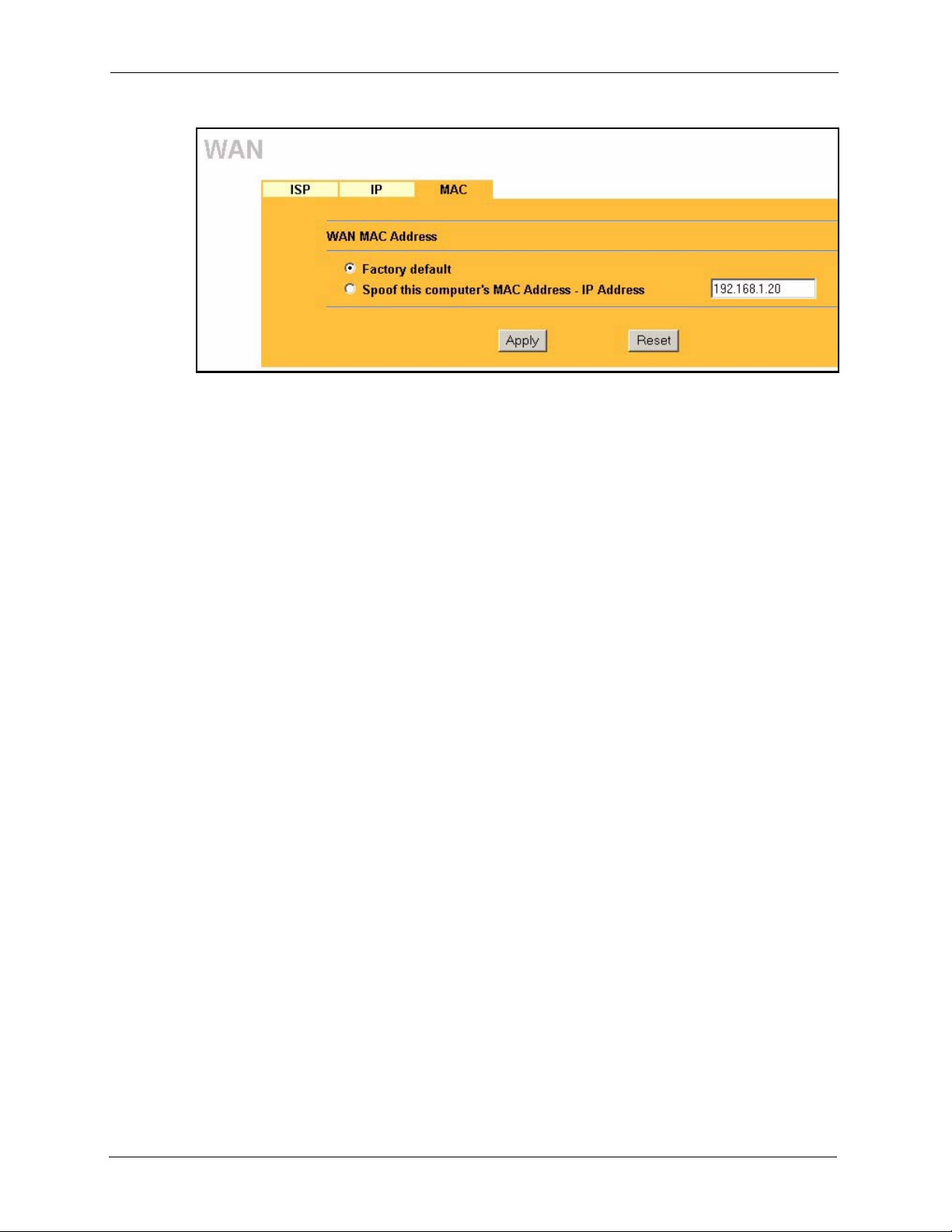
P-2302R Series User’s Guide
Figure 26 MAC Setup
Every Ethernet device has a unique MAC (Media Access Control) address. The MAC address
is assigned at the factory and consists of six pairs of hexadecimal characters, for example,
00:A0:C5:00:00:02.
The MAC address screen allows users to configure the WAN port's MAC address by either
using the factory default or cloning your computer’s MAC address. Choose Factory Default
to select the factory assigned default MAC Address.
Otherwise, click Spoof this computer's MAC address - IP Address and enter the IP address
of your computer. Once it is successfully configured, the address will be copied to the rom file
(ZyNOS configuration file). It will not change unless you change the setting or upload a
different ROM file.
It is recommended that you clone the MAC address prior to hooking up
the WA N Port.
89 Chapter 6 WAN Screens

This chapter provides background information on VoIP and SIP.
7.1 VoIP Introduction
VoIP (Voice over IP) is the sending of voice signals over the Internet Protocol. This allows
you to make phone calls and send faxes over the Internet at a fraction of the cost of using the
traditional circuit-switched telephone network. You can also use servers to run telephone
service applications like PBX services and voice mail. Internet Telephony Service Provider
(ITSP) companies provide VoIP service. A company could alternatively set up an IP-PBX and
provide it’s own VoIP service.
P-2302R Series User’s Guide
CHAPTER 7
Introduction to VoIP
Circuit-switched telephone networks require 64 kilobits per second (kbps) in each direction to
handle a telephone call. VoIP can use advanced voice coding techniques with compression to
reduce the required bandwidth.
7.2 Introduction to SIP
The Session Initiation Protocol (SIP) is an application-layer control (signaling) protocol that
handles the setting up, altering and tearing down of voice and multimedia sessions over the
Internet.
SIP signaling is separate from the media for which it handles sessions. The media that is
exchanged during the session can use a different path from that of the signaling. SIP handles
telephone calls and can interface with traditional circuit-switched telephone networks.
7.2.1 SIP Identities
A SIP account uses an identity (sometimes referred to as a SIP address). A complete SIP
identity is called a SIP URI (Uniform Resource Identifier). A SIP account's URI identifies the
SIP account in a way similar to the way an e-mail address identifies an e-mail account. The
format of a SIP identity is SIP-Number@SIP-Service-Domain.
7.2.1.1 SIP Number
The SIP number is the part of the SIP URI that comes before the “@” symbol. A SIP number
can use letters like in an e-mail address (johndoe@your-ITSP.com for example) or numbers
like a telephone number (1122334455@VoIP-provider.com for example).
Chapter 7 Introduction to VoIP 90

P-2302R Series User’s Guide
7.2.1.2 SIP Service Domain
The SIP service domain of the VoIP service provider is the domain name in a SIP URI. For
example, if the SIP address is 1122334455@VoIP-provider.com
the SIP service domain.
7.2.2 SIP Call Progression
The following figure displays the basic steps in the setup and tear down of a SIP call. A calls
B.
Table 19 SIP Call Progression
A B
1. INVITE
4. ACK
5.Dialogue (voice traffic)
6. BYE
, then “VoIP-provider.com” is
2. Ringing
3. OK
7. OK
1 A sends a SIP INVITE request to B. This message is an invitation for B to participate in a
SIP telephone call.
2 B sends a response indicating that the telephone is ringing.
3 B sends an OK response after the call is answered.
4 A then sends an ACK message to acknowledge that B has answered the call.
5 Now A and B exchange voice media (talk).
6 After talking, A hangs up and sends a BYE request.
7 B replies with an OK response confirming receipt of the BYE request and the call is
terminated.
7.2.3 SIP Client Server
SIP is a client-server protocol. A SIP client is an application program or device that sends SIP
requests. A SIP server responds to the SIP requests.
When you use SIP to make a VoIP call, it originates at a client and terminates at a server. A
SIP client could be a computer or a SIP phone. One device can act as both a SIP client and a
SIP server.
91 Chapter 7 Introduction to VoIP

7.2.3.1 SIP User Agent
A SIP user agent can make and receive VoIP telephone calls. This means that SIP can be used
for peer-to-peer communications even though it is a client-server protocol. In the following
figure, either A or B can act as a SIP user agent client to initiate a call. A and B can also both
act as a SIP user agent to receive the call.
Figure 27 SIP User Agent
7.2.3.2 SIP Proxy Server
A SIP proxy server receives requests from clients and forwards them to another server.
In the following example, you want to use client device A to call someone who is using client
device C.
P-2302R Series User’s Guide
1 The client device (A in the figure) sends a call invitation to the SIP proxy server (B).
2 The SIP proxy server forwards the call invitation to C.
Figure 28 SIP Proxy Server
Chapter 7 Introduction to VoIP 92
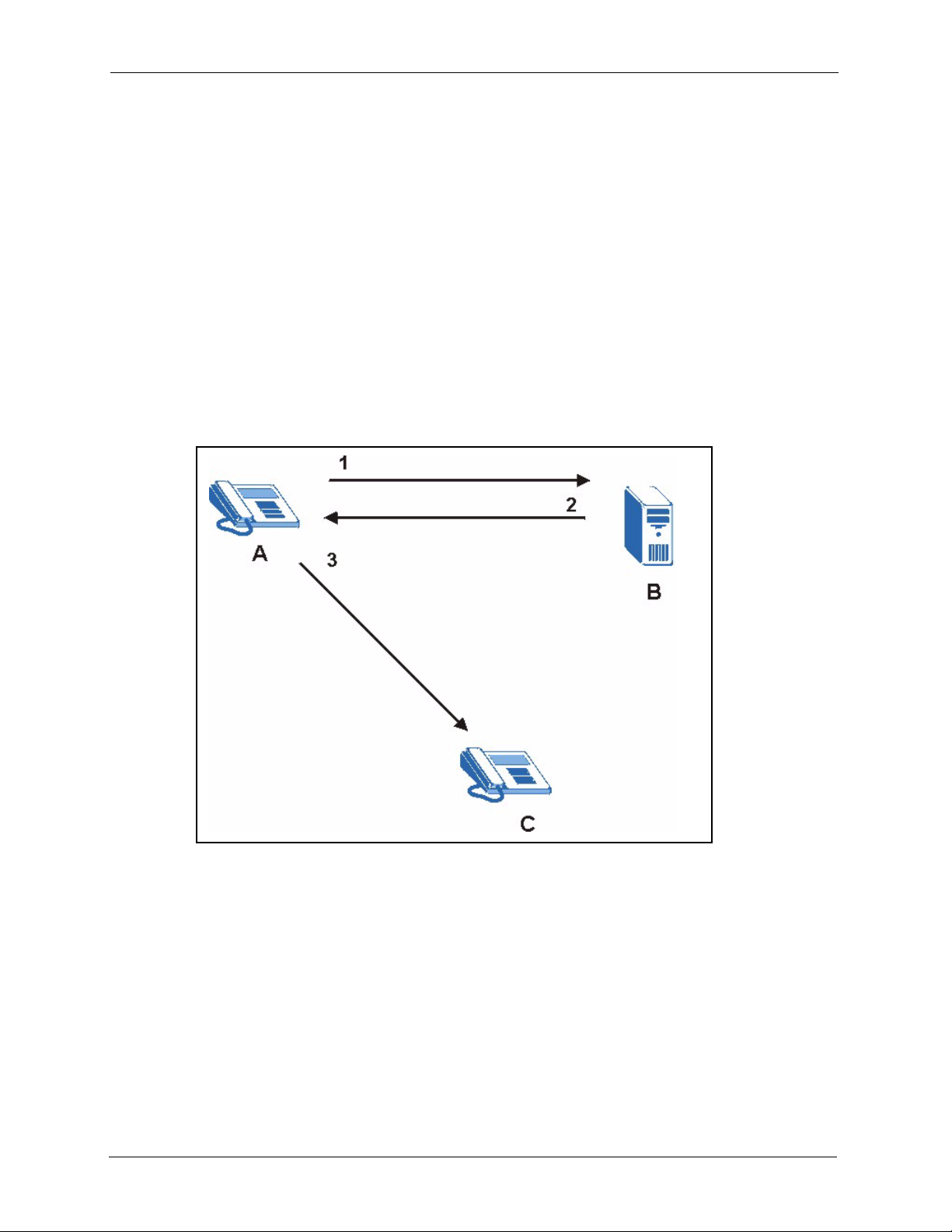
P-2302R Series User’s Guide
7.2.3.3 SIP Redirect Server
A SIP redirect server accepts SIP requests, translates the destination address to an IP address
and sends the translated IP address back to the device that sent the request. Then the client
device that originally sent the request can send requests to the IP address that it received back
from the redirect server. Redirect servers do not initiate SIP requests.
In the following example, you want to use client device A to call someone who is using client
device C.
1 Client device A sends a call invitation for C to the SIP redirect server (B).
2 The SIP redirect server sends the invitation back to A with C’s IP address (or domain
name).
3 Client device A then sends the call invitation to client device C.
Figure 29 SIP Redirect Server
7.2.3.4 SIP Register Server
A SIP register server maintains a database of SIP identity-to-IP address (or domain name)
mapping. The register server checks your user name and password when you register.
7.2.4 RTP
When you make a VoIP call using SIP, the RTP (Real time Transport Protocol) is used to
handle voice data transfer. See RFC 1889 for details on RTP.
93 Chapter 7 Introduction to VoIP
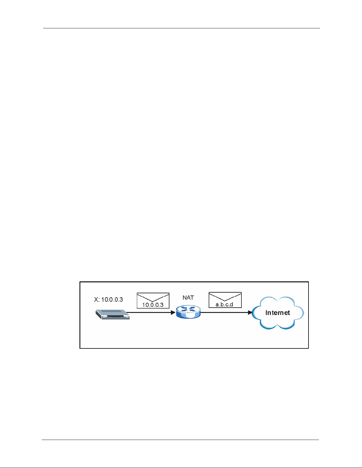
7.3 NAT
NAT (Network Address Translation - NAT, RFC 1631) is the translation of the IP address of a
host in a packet. For example, the source address of an outgoing packet, used within one
network is changed to a different IP address known within another network.
In the simplest form, NAT changes the source IP address of a packet received from a device to
another IP address before forwarding the packet towards the destination. When the response
comes back, NAT translates the destination address back to the device’s IP address and
forwards it to the device.
NAT routers are commonly used to translate private (or internal) IP addresses in packet
headers to public (or external) IP addresses and vice versa. A NAT router maps a private IP
address and port pair to a public IP address and port, and whenever the NAT router receives a
packet with that public IP address and port, it knows how to reroute the packet back to the
private IP address and port.
NAT may be implemented on a device that is between your Prestige and the Internet.
P-2302R Series User’s Guide
7.3.1 NAT Example
See the following figure. The Prestige (X) sends packets to the Internet. The Prestige’s IP
address is 10.0.0.3. This is a private or internal IP address. The NAT router maps the private
source IP address to a public source IP address (a.b.c.d). The public source IP address is also
known as the external IP address.
Note: The NAT figures in this chapter use lower-case letters (like a.b.c.d for example)
to represent public IP addresses.
Figure 30 NAT: Outgoing
When the NAT router receives packets with destination address IP address a.b.c.d, the NAT
router changes a.b.c.d back to the private IP address 10.0.0.3 and sends it to the Prestige.
Chapter 7 Introduction to VoIP 94

P-2302R Series User’s Guide
Figure 31 NAT: Incoming
7.3.2 NAT Types
This section discusses the following NAT types that may be implemented on a router in front
of the Prestige.
• Full Cone
• Restricted Cone
• Port Restricted Cone
• Symmetric
The following table summarizes how these NAT types handle outgoing and incoming packets.
Read the following sections for more details and examples.
Table 20 NAT Types
PORT
RESTRICTED
CONE
Only external hosts
with an IP address
and port to which
the internal host
has already sent a
packet can send
packets to the
mapped external IP
address and port.
SYMMETRIC
A host on the external
network can only send
packets to the specific
mapped external IP
address and port that the
NAT router used in
sending a packet to the
external host’s IP address
and port.
The NAT router maps the
internal IP address and
port of each outgoing
packet to a different
external IP address and
port for each different
destination IP address
and port.
Incoming
Packets
Outgoing
Packets
FULL CONE
Any external host
can send packets to
the mapped
external IP address
and port.
The NAT router maps the internal IP address and port of all
outgoing packets to a single IP address and port on the
external network.
RESTRICTED
CONE
Only external hosts
with an IP address
to which the internal
host has already
sent a packet can
send packets to the
mapped external IP
address and port.
The examples in these NAT type sections describe NAT translation between internal (private)
and external (public) IP addresses.
95 Chapter 7 Introduction to VoIP

7.3.2.1 Full Cone NAT
In full cone NAT, the NAT router maps all outgoing packets from an internal IP address and
port to a single IP address and port on the external network. The NAT router also maps
packets coming to that external IP address and port to the internal IP address and port.
In the following example, the NAT router maps the source address of all packets sent from the
Prestige’s internal IP address 1 and port A to IP address 2 and port B on the external network.
The NAT router also performs NAT on all incoming packets sent to IP address 2 and port B
and sends them to IP address 1, port A.
Figure 32 Full Cone NAT Example
P-2302R Series User’s Guide
7.3.2.2 Restricted Cone NAT
As in full cone NAT, a restricted cone NAT router maps all outgoing packets from an internal
IP address and port to a single IP address and port on the external network. In the following
example, the NAT router maps the source address of all packets sent from internal IP address
1 and port A to IP address 2 and port B on the external network.
The difference from full cone NAT is in how the restricted cone NAT router handles packets
coming in from the external network. A host on the external network (IP address 3 or IP
address 4 for example) can only send packets to the internal host if the internal host has
already sent a packet to the external host’s IP address.
A Prestige with IP address 1 and port A sends packets to IP address 3 and IP address 4. The
NAT router changes the Prestige’s IP address to 2 and port to B.
Both 4, D and 4, E can send packets to 2, B since 1, A has already sent packets to 4. The NAT
router will perform NAT on the packets from 4, D and 4, E and send them to the Prestige at IP
address 1, port A. Packets have not been sent from 1, A to 3 or 5, so 3 and 5 cannot send
packets to 1, A.
Chapter 7 Introduction to VoIP 96

P-2302R Series User’s Guide
Figure 33 Restricted Cone NAT Example
7.3.2.3 Port Restricted Cone NAT
As in full cone NAT, a port restricted cone NAT router maps all outgoing packets from an
internal IP address and port to a single IP address and port on the external network. In the
following example, the NAT router maps the source address of all packets sent from internal
IP address 1 and port A to IP address 2 and port B on the external network.
The difference from full cone and restricted cone NAT is in how the port restricted cone NAT
router handles packets coming in from the external network. A host on the external network
(IP address 3 and Port C for example) can only send packets to the internal host if the internal
host has already sent a packet to the external host’s IP address and port.
A Prestige with IP address 1 and port A sends packets to IP address 3, port C and IP address 4,
port D. The NAT router changes the Prestige’s IP address to 2 and port to B.
Since 1, A has already sent packets to 3, C and 4, D, they can send packets back to 2, B and the
NAT router will perform NAT on them and send them to the Prestige at IP address 1, port A.
Packets have not been sent from 1, A to 4, E or 5, so they cannot send packets to 1, A.
97 Chapter 7 Introduction to VoIP

Figure 34 Port Restricted Cone NAT Example
7.3.2.4 Symmetric NAT
The full, restricted and port restricted cone NAT types use the same mapping for an outgoing
packet’s source address regardless of the destination IP address and port. In symmetric NAT,
the mapping of an outgoing packet’s source address to a source address in another network is
different for each different destination IP address and port.
P-2302R Series User’s Guide
In the following example, the NAT router maps the Prestige’s source address IP address 1 and
port A to IP address 2 and port B on the external network for packets sent to IP address 3 and
port B. The NAT router uses a different mapping (IP address 2 and port M) when the Prestige
sends packets to IP address 4 and port D.
A host on the external network (IP address 3 and port C for example) can only send packets to
the internal host via the external IP address and port that the NAT router used in sending a
packet to the external host’s IP address and port. So in the example, only 3, C is allowed to
send packets to 2, B and only 4, D is allowed to send packets to 2, M.
Chapter 7 Introduction to VoIP 98
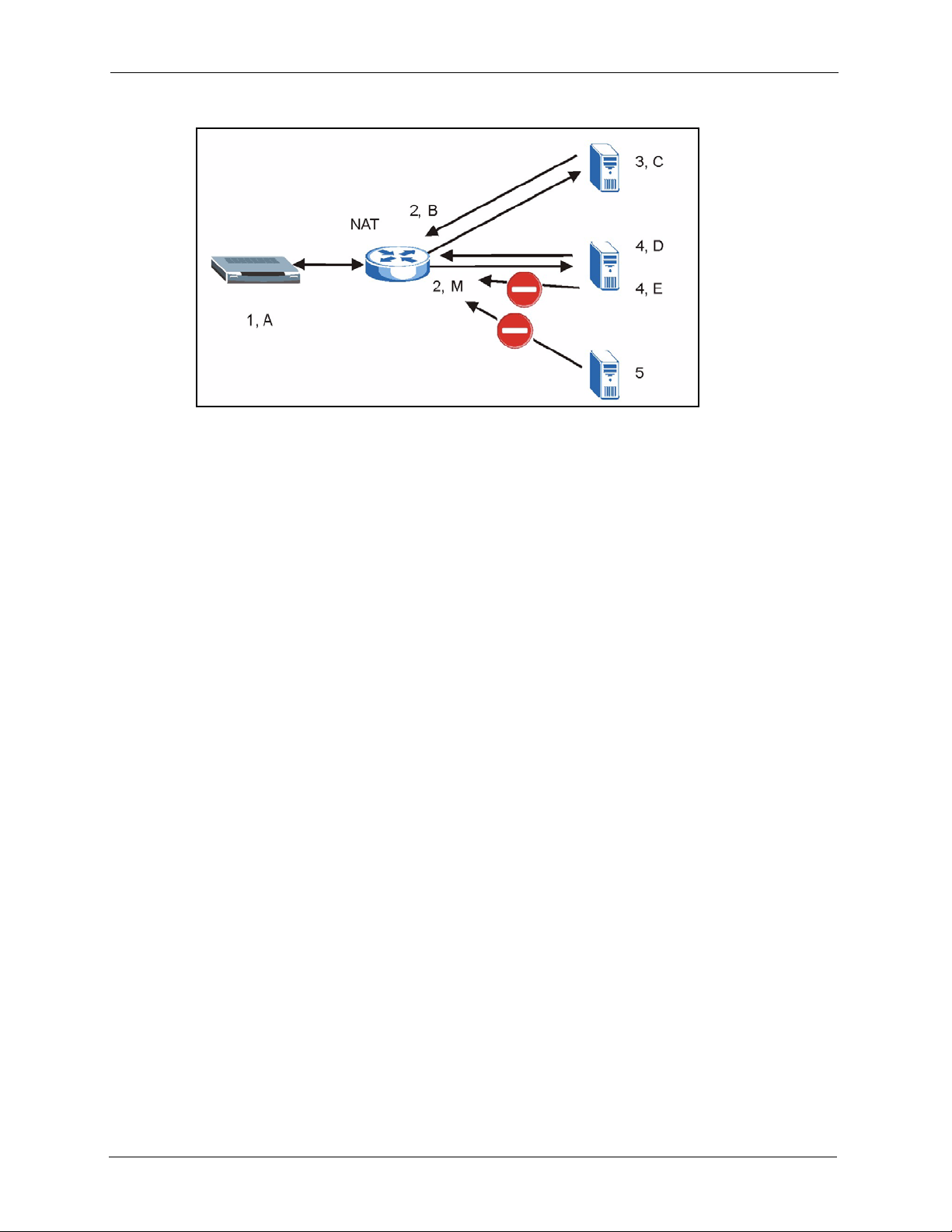
P-2302R Series User’s Guide
Figure 35 Symmetric NAT
7.4 NAT and SIP
The Prestige must register its public IP address with a SIP register server. If there is a NAT
router between the Prestige and the SIP register server, the Prestige probably has a private IP
address. The Prestige lists its IP address in the SIP message that it sends to the SIP register
server. NAT does not translate this IP address in the SIP message. The SIP register server gets
the Prestige’s IP address from inside the SIP message and maps it to your SIP identity. If the
Prestige has a private IP address listed in the SIP message, the SIP server cannot map it to your
SIP identity.
A SIP ALG (Application Layer Gateway) or the Use NAT, STUN, and outbound proxy
features allow the Prestige to list its public IP address in the SIP messages.
7.5 SIP ALG
Some NAT routers may include a SIP Application Layer Gateway (ALG). A SIP ALG allows
SIP calls to pass through NAT by examining and translating IP addresses embedded in the
data stream. When the Prestige registers with the SIP register server, the SIP ALG translates
the Prestige’s private IP address inside the SIP data stream to a public IP address. You do not
need to use STUN or an outbound proxy if your Prestige is behind a SIP ALG.
7.6 Use NAT
If you know the NAT router’s public IP address and SIP port number, you can use the Use
NAT feature to manually configure the Prestige to use a them in the SIP messages. This
eliminates the need for STUN or a SIP ALG.
You must also configure the NAT router to forward traffic with this port number to the
Prestige.
99 Chapter 7 Introduction to VoIP
 Loading...