

Page 1

Prestige 660W/HW Series
ADSL 2/2+ Gateway with 802.11g Wireless
Compact Guide
Version 3.40
May 2004
Page 2

Prestige 660W/HW Series Compact Guide
Table of Contents
1 Introducing the Prestige..............................................................................................4
2 Hardware .....................................................................................................................5
2.1 Rear Panel Connections.........................................................................................5
2.2 The Front Panel LEDs ...........................................................................................6
3 Internet Access With Zero Configuration ...............................................................10
4 Setting Up Your Computer’s IP Address ................................................................11
4.1 Windows 95/98/Me...............................................................................................11
4.2 Windows 2000/NT/XP ..........................................................................................14
4.3 Checking/Updating Your Computer’s IP Address................................................ 15
4.4 Testing the Connection to the Prestige.................................................................15
5 Configuring Your Prestige........................................................................................17
5.1 Accessing Your Prestige Via Web Configurator ..................................................17
5.2 Common Screen Command Buttons.....................................................................18
5.3 Internet Access Using the Wizard ........................................................................19
5.4 Test Your Internet Connection ............................................................................. 24
6 Advanced Configuration...........................................................................................25
6.1 Wireless LAN Setup..............................................................................................25
6.2 Wireless LAN Security Setup................................................................................27
6.3 802.1x and WPA Overview...................................................................................29
6.4 Network Address Translation Overview...............................................................29
2
Page 3

Prestige 660W/HW Series Compact Guide
6.5 Configuring SUA Server ......................................................................................30
6.6 Firewall Overview................................................................................................32
6.7 Enabling the Firewall ..........................................................................................33
6.8 Procedure for Configuring Firewall Rules ..........................................................33
6.9 Configuring Source and Destination Addresses...................................................37
7 Troubleshooting.........................................................................................................39
3
Page 4

Prestige 660W/HW Series Compact Guide
1 Introducing the Prestige
The Prestige 660W/HW ADSL 2/2+ Gateway with 802.11g Wireless is the ideal all-inone device for small networks connecting to the Internet via ADSL. Key features of the
Prestige include NAT, 802.1x wireless LAN security, WPA (Wi-Fi Protected Access)
and Firewall. See your User’s Guide for more details on all Prestige features.
You should have an Internet account already set up and have been given most of the
following information.
INTERNET ACCOUNT INFORMATION
Your device’s WAN IP Address (if given): __________________
DNS Server IP Address (if given): Primary __________________,
Secondary _________________
Virtual Path Identifier (VPI): ____________
Virtual Channel Identifier (VCI): ____________
Multiplexing (VC-based or LLC-based):
Encapsulation: (choose one below)
RFC 1483
ENET ENCAP
PPPoA
PPPoE
Ethernet Encapsulation Gateway IP Address:
__________________
User Name: ____________ Password: ____________
Service Name: ____________
User Name: ____________ Password: ____________
VC LLC
Certifications
1. Go to www.zyxel.com
2. Select your product from the drop-down list box on the ZyXEL home page to go to
that product's page.
3. Select the certification you wish to view from this page.
4
Page 5
Prestige 660W/HW Series Compact Guide
2 Hardware
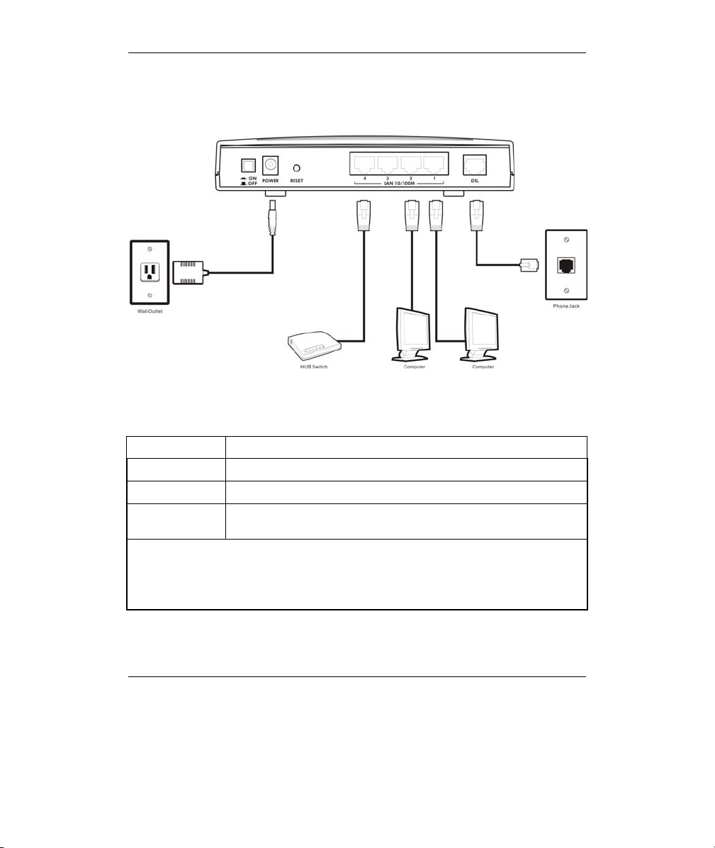
2.1 Rear Panel Connections
Figure 1 P660HW Hardware Connections
Table 1 Prestige Rear Panel Description
LABEL DESCRIPTION
DSL Connect to a telephone jack using the included phone wire.
LAN 1 to LAN 4 Connect to a computer/external hub using an Ethernet cable.
POWER Connect to a power source using the power adaptor for your region
(see your User’s Guide).
After you’ve made the connections, connect the power adaptor to a power supply and
push in the power button to turn on the Prestige.
The PWR/SYS LED blinks while performing system testing and then turns steady on if
the testing is successful. A LAN LED turns on if a LAN port is properly connected.
5
Page 6
Prestige 660W/HW Series Compact Guide
Table 1 Prestige Rear Panel Description
LABEL DESCRIPTION
RESET You only need to use this button if you’ve forgotten the Prestige’s
password. It returns the Prestige to the factory defaults (password is
1234, LAN IP address 192.168.1.1 etc.; see your User’s Guide for
details).
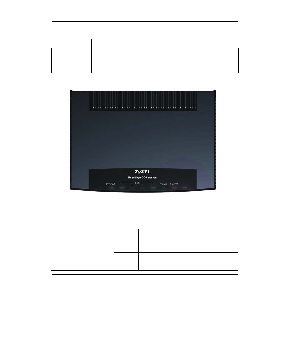
2.2 The Front Panel LEDs
Figure 2 P660HW Front Panel
Refer to the following table for more detailed LED descriptions.
Table 2 P660HW Front Panel LED Description
LED COLOR STATUS DESCRIPTION
PWR/SYS
Green
Red On Power to the Prestige is too low.
On The Prestige is receiving power and
functioning properly.
Blinking The Prestige is rebooting.
6
Page 7

Prestige 660W/HW Series Compact Guide
Table 2 P660HW Front Panel LED Description
LED COLOR STATUS DESCRIPTION
Off The system is not ready or has
LAN 1 to LAN 4
WLAN Green
DSL/PPP
Green
Amber
Off The LAN is not connected.
Green
Off The DSL link is down.
On The Prestige has a successful 10Mb Ethernet
Blinking The Prestige is sending/receiving data.
On The Prestige has a successful 100Mb
Blinking The Prestige is sending/receiving data.
On The Prestige is ready, but is not
Blinking The Prestige is sending/receiving data
Off The wireless LAN is not ready or has failed.
Fast
Blinking
Slow
Blinking
On The system is ready, but is not
On The connection to the PPPoE server is up. Amber
Blinking The Prestige is sending/receiving PPP data.
malfunctioned.
connection.
Ethernet connection.
sending/receiving data through the wireless
LAN.
through the wireless LAN.
The Prestige is sending/receiving non-PPP
data.
The Prestige is initializing the DSL line.
sending/receiving non-PPP data.
7
Page 8
Prestige 660W/HW Series Compact Guide
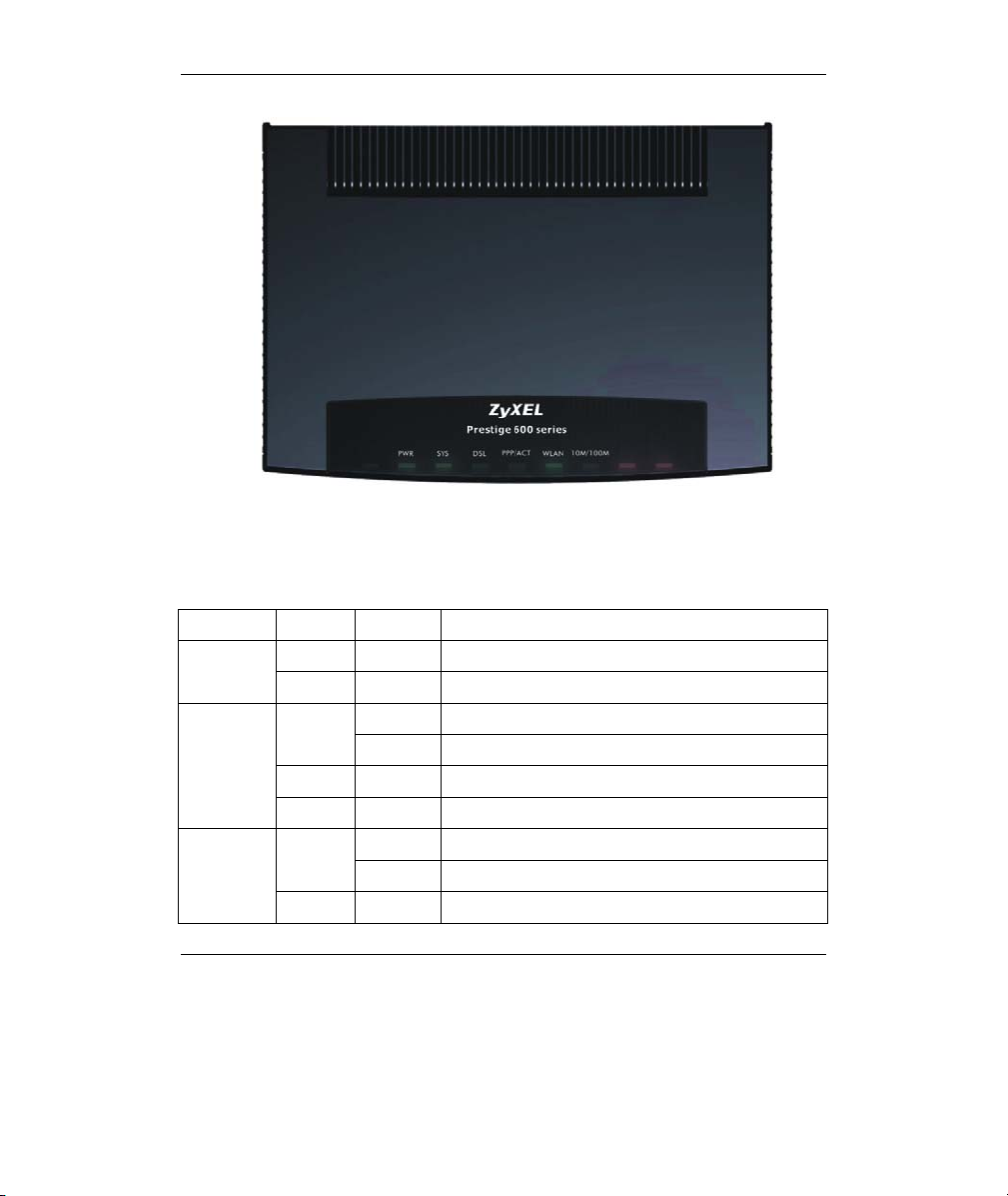
Figure 3 P660W Front Panel
Refer to the following table for more detailed LED descriptions.
Table 3 P660W Front Panel LED Description
LED COLOR STATUS DESCRIPTION
Green On The Prestige is receiving power. PWR
Off The Prestige is not receiving power.
SYS
Red On Power to the Prestige is too low.
Off The system is not ready or has malfunctioned.
DSL
Off The DSL link is down.
On The Prestige is functioning properly. Green
Blinking The Prestige is rebooting.
On The Prestige is linked successfully to a DSLAM. Green
Blinking The Prestige is initializing the DSL line.
8
Page 9

Prestige 660W/HW Series Compact Guide
Table 3 P660W Front Panel LED Description
LED COLOR STATUS DESCRIPTION
PPP/ACT
WLAN Green
10M/100M
Green Blinking The Prestige is sending/receiving non-PPP data.
Amber
Off The system is ready, but is not sending/receiving
Green
Amber
Off The LAN is not connected.
On The Prestige has a PPP (PPPoA or PPPoE)
connection.
Blinking The Prestige is sending/receiving PPPoA or
PPPoE traffic.
data.
On The Prestige is ready, but is not sending/receiving
data through the wireless LAN.
Blinking The Prestige is sending/receiving data through the
wireless LAN.
Off The wireless LAN is not ready or has failed.
On The Prestige has a successful 10Mb Ethernet
connection.
Blinking The Prestige is sending/receiving data.
On The Prestige has a successful 100Mb Ethernet
connection.
Blinking The Prestige is sending/receiving data.
9
Page 10
Prestige 660W/HW Series Compact Guide
3 Internet Access With Zero
Configuration
With the Prestige’s Zero Configuration, you can access the Internet easily.
Simply connect a computer to the Prestige and access the Internet without
changing the network settings (such as the IP address and subnet mask) of the
computer.
Step 1. Make the hardware connections and turn on the Prestige (refer to
the Rear Panel Connections section).
Step 2. Wait until the DSL/ACT LED turns steady on. Launch your web
browser and navigate to a web site (for example, www.zyxel.com
The Prestige automatically detects and configures your Internet
connection. This may take about two minutes.
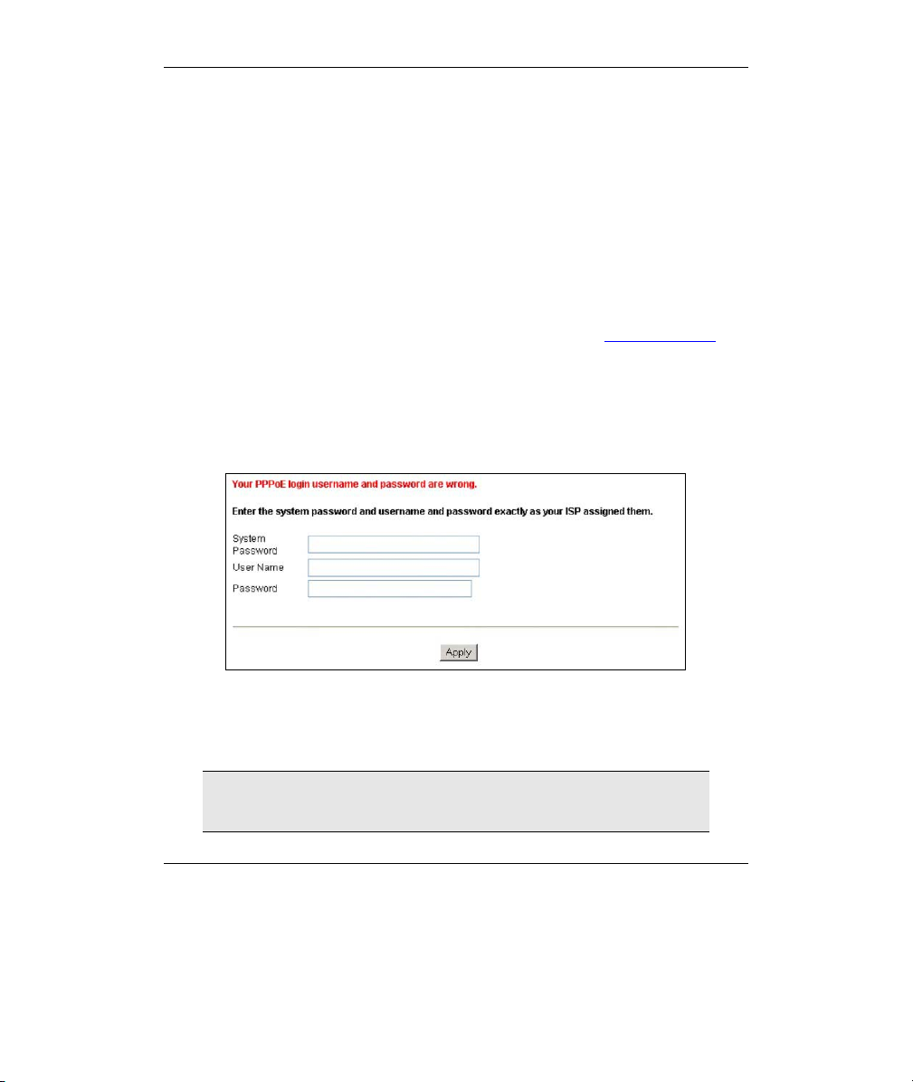
Step 3. If you have a PPPoE or PPPoA connection type, a screen displays
prompting you to enter your Internet account username and/or
password. Enter the username, password and/or service name
exactly as provided by your ISP. Click Apply.
).
Step 4. You should be able to access the Internet. Otherwise, follow the on-
screen instructions to solve the problem(s). Refer to the rest of this
guide or the User’s Guide to manually configure your Prestige for
Internet connection and other advanced settings.
If an Internet access parameter changes, either change it
manually or restart the device to have the Prestige automatically
reconfigure your Internet connection.
10
Page 11
Prestige 660W/HW Series Compact Guide
4 Setting Up Your Computer’s IP
Address
Skip this section if your computer is already set up to accept a
dynamic IP address. This is the default for most new computers.
The Prestige is already set up to assign your computer an IP address. Use this section to
set up your computer to receive an IP address or assign it a static IP address in the
192.168.1.2 to 192.168.1.254 range with a subnet mask of 255.255.255.0. This is
necessary to ensure that your computer can communicate with your Prestige.
Your computer must have an Ethernet card and TCP/IP installed. TCP/IP should already
be installed on computers using Windows NT/2000/XP, Macintosh OS 7 and later
operating systems.
4.1 Windows 95/98/Me
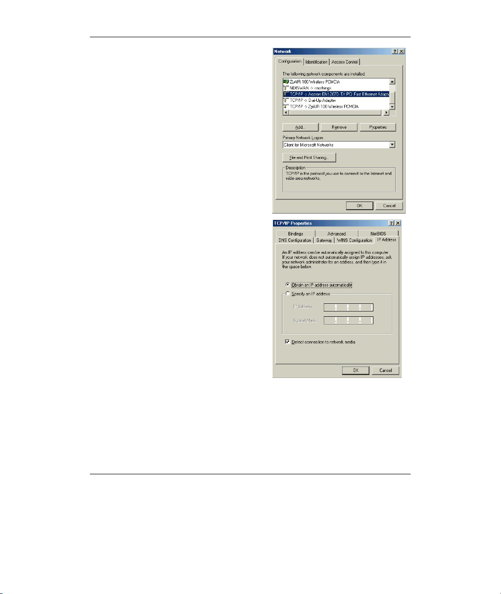
Click Start, Settings, Control Panel and double-click the Network icon to
1.
open the Network window.
The Network window Configuration tab displays a list of installed
2.
components. You need a network adapter, the TCP/IP protocol and Client
for Microsoft Networks.
11
Page 12
Prestige 660W/HW Series Compact Guide
In the Network window
3.
Configuration tab, select your
network adapter's TCP/IP entry and
click Properties.
4. Click the IP Address tab.
-If your IP address is dynamic, select
Obtain an IP address automatically.
-If you have a static IP address, select
Specify an IP address and type your
information into the IP Address and
Subnet Mask fields.
12
Page 13

Prestige 660W/HW Series Compact Guide
5. Click the DNS Configuration tab.
-If you do not know your DNS
information, select Disable DNS.
-If you know your DNS information, select
Enable DNS and type the information in
the fields below (you may not need to fill
them all in).
6.
Click the Gateway tab.
-If you do not know your gateway’s IP
address, remove previously installed
gateways.
-If you have a gateway IP address, type it
in the New gateway field and click Add.
7. Click OK to save and close the TCP/IP Properties window.
13
Page 14

Prestige 660W/HW Series Compact Guide
8. Click OK to close the Network window. Insert the Windows CD if prompted.
9. Turn on your Prestige and restart your computer when prompted.
Verifying Your Computer’s IP Address
1. Click Start and then Run.
2. In the Run window, type "winipcfg" and then click OK to open the IP
Configuration window.
3. Select your network adapter. You should see your computer's IP address, subnet
mask and default gateway.
4.2 Windows 2000/NT/XP
1. In Windows XP, click start, Control Panel. In Windows 2000/NT, click Start,
Settings, Control Panel.
2. In Windows XP, click Network Connections.
In Windows 2000/NT, click Network and Dial-up Connections.
3. Right-click Local Area Connection and then click Properties.
4. Select Internet Protocol (TCP/IP) (under the General tab in Win XP) and click
Properties.
5. The Internet Protocol TCP/IP Properties
screen opens (the General tab in
Windows XP).
- To have your computer assigned a
dynamic IP address, click Obtain an IP
address automatically.
If you know your DNS sever IP
address(es), type them in the Preferred
DNS server and/or Alternate DNS
server fields.
-To configure a static IP address, click
Use the following IP Address and fill in
the IP address (choose one
from192.168.1.2 to 192.168.1.254),
Subnet mask (255.255.255.0), and
Default gateway (192.168.1.1) fields.
14
Page 15

Prestige 660W/HW Series Compact Guide
Then enter your DNS server IP address(es) in the Preferred DNS server and/or
Alternate DNS server fields.
If you have more than two DNS servers, click Advanced, the DNS tab and then
configure them using Add.
6. Click Advanced. Remove any previously
installed gateways in the IP Settings tab
and click OK to go back to the Internet
Protocol TCP/IP Properties screen.
7. Click OK to close the Internet Protocol
(TCP/IP) Properties window.
8. Click OK to close the Local Area
Connection Properties window.
4.3 Checking/Updating Your Computer’s IP Address
1. In the computer, click Start, (All) Programs, Accessories and then Command
Prompt.
2. In the Command Prompt window, type "ipconfig" and then press ENTER to verify
that your computer’s IP address is in the correct range (192.168.1.2 to
192.168.1.254) with subnet mask 255.255.255.0. This is necessary in order to
communicate with the Prestige.
Refer to your User’s Guide for detailed IP address configuration for other Windows and
Macintosh computer operating systems.
4.4 Testing the Connection to the Prestige
1. Click Start, (All) Programs, Accessories and then Command Prompt.
2. In the Command Prompt window, type "ping” followed by a space and the IP
address of the Prestige (192.168.1.1 is the default).
3. Press ENTER and the following screen displays.
15
Page 16

Prestige 660W/HW Series Compact Guide
,
C:\>ping 192.168.1.1
Pinging 192.168.1.1 with 32 bytes of data:
Reply from 192.168.1.1: bytes=32 time=10ms TTL=254
Reply from 192.168.1.1: bytes=32 time<10ms TTL=254
Reply from 192.168.1.1: bytes=32 time<10ms TTL=254
Reply from 192.168.1.1: bytes=32 time<10ms TTL=254
Ping statistics for 192.168.1.1:
Packets: Sent = 4, Received = 4, Lost = 0 (0% loss),
Approximate round trip times in milli-seconds:
Minimum = 0ms
Maximum = 10ms, Average = 2ms
Your computer can now communicate with the Prestige using the LAN port.
16
Page 17

Prestige 660W/HW Series Compact Guide
5 Configuring Your Prestige
This Compact Guide shows you how to use the web
configurator only. See your User’s Guide for background
information on all Prestige features and SMT (System
Management Terminal) configuration.
5.1 Accessing Your Prestige Via Web Configurator
Step 1. Launch your web browser. Enter “192.168.1.1” as the web site address.
Web site address.
Figure 4 Entering Prestige LAN IP Address in Internet Explorer
Step 2. An Enter Network Password window displays. Enter the user name
(“admin” is the default), password (“1234” is the default) and click OK.
Default user name.
Figure 5 Web Configurator: Password Screen
Step 3. You should now see the web configurator Site Map screen.
Click Wizard Setup to begin a series of screens to configure your Prestige for
the first time.
Click a link under Advanced Setup to configure advanced Prestige features.
17
Page 18

Prestige 660W/HW Series Compact Guide
Click a link under Maintenance to see Prestige performance statistics, upload
firmware and back up, restore or upload a configuration file.
Click Logout in the navigation panel when you have finished a Prestige
management session.
WIZARD
Navigation panel
LOGOUT
Figure 6 Web Configurator: Site Map Screen
The Prestige automatically times out after five minutes of
inactivity. Simply log back into the Prestige if this happens to
you.
5.2 Common Screen Command Buttons
The following table shows common command buttons found on many web configurator
screens.
Back Click Back to return to the previous screen.
Apply Click Apply to save your changes back to the Prestige.
Reset/Cancel Click Reset or Cancel to begin configuring this screen afresh.
18
Page 19

Prestige 660W/HW Series Compact Guide
5.3 Internet Access Using the Wizard
Use the Wizard Setup screens to configure your system for Internet access settings and
fill in the fields with the information in the Internet Account Information table. Your ISP
may have already configured some of the fields in the wizard screens for you.
Step 1. In the Site Map screen click Wizard Setup to display the first wizard
screen.
From the Mode drop-down list box, select
Routing (default) if your ISP allows
multiple computers to share an Internet
account. Otherwise select Bridge.
Select the encapsulation type your ISP
uses from the Encapsulation drop-down
list box. Choices vary depending on what
you select in the Mode field.
Select the multiplexing method used by
your ISP from the Multiplex drop-down
list box.
Enter the correct Virtual Path Identifier
(VPI) and Virtual Channel Identifier (VCI)
numbers supplied by your ISP in the VPI
and VCI fields. These fields may already
be configured.
Figure 7 Wizard Screen 1
Click Next.
Step 2. The second wizard screen varies depending on what mode and
encapsulation type you use. All screens shown are with routing mode.
Configure the fields and click Next to continue.
19
Page 20

Prestige 660W/HW Series Compact Guide
If your ISP provides the name of
your PPPoE service provider,
enter it in the Service Name
field.
Enter the user name and
password exactly as your ISP
assigned them.
Select Obtain an IP Address
Automatically if you have a
dynamic IP address; otherwise
select Static IP Address and
type your ISP assigned IP
address in the text box below.
Select Connect on Demand
when you don't want the
connection up all the time and
specify an idle time-out period (in
seconds) in the Max. Idle
Figure 8 Internet Connection with PPPoE
Select Nailed-Up Connection when you want your connection up all the time. The
Prestige will try to bring up the connection automatically if it is disconnected
From the Network Address Translation drop-down list box, select SUA Only, Full
Feature or None. Refer to the Network Address Translation section for more information.
Timeout field.
Enter the IP address given by
your ISP in the IP Address field.
Figure 9 Internet Connection with RFC 1483
20
The IP Address
field is not
available for
bridge mode.
Refer to Figure 8 for description
of the Network Address
Translation field.
Page 21

Prestige 660W/HW Series Compact Guide
Figure 10 Internet Connection with ENET
ENCAP
In the ENET ENCAP Gateway
field, enter the gateway IP
address given by your ISP.
Refer to Figure 8 for other field
descriptions
.
Refer to Figure 8 for field
descriptions.
The IP Address
and Network
Address
Translation fields
are not available
for bridge mode.
Figure 11 Internet Connection with PPPoA
21
Page 22

Prestige 660W/HW Series Compact Guide
Step 3. Verify the settings in the screen shown next. To change the LAN
information on the Prestige, click Change LAN Configurations.
Otherwise click Save Settings to save the configuration and skip the
following step.
Figure 12 Wizard Screen 3
Step 5. If you want to change your Prestige LAN settings, click Change LAN
Configuration to display the screen as shown next.
22
Page 23

Prestige 660W/HW Series Compact Guide
Enter the IP address of your Prestige in
dotted decimal notation in the LAN IP
Address field. For example,
192.168.1.1 (factory default).
If you change the
Prestige’s LAN IP
address, you must use
the new IP address if
you want to access the
web configurator
again.
Enter a subnet mask in dotted decimal
notation in the LAN Subnet Mask field.
Figure 13 Wizard: LAN Configuration
From the DHCP Server drop-down list box, select On to allow your Prestige to assign IP
addresses, an IP default gateway and DNS servers to computer systems that support the
DHCP client. Select Off to disable DHCP server.
When DHCP server is used, set the following items:
Specify the first of the contiguous addresses in the IP address pool in the Client IP Pool
Starting Address field.
Specify the size or count of the IP address pool in the Size of Client IP Pool field.
Enter the IP address(es) of the DNS server(s) in the Primary DNS Server and/or
Secondary DNS Server fields.
Step 6. The Prestige automatically tests the connection to the computer(s)
connected to the LAN ports. To test the connection from the Prestige
to the ISP, click Start Diagnose. Otherwise click Return to Main
Menu to go back to the Site Map screen.
23
Page 24

Prestige 660W/HW Series Compact Guide
Figure 14 Wizard Screen 4
5.4 Test Your Internet Connection
Launch your web browser and navigate to www.zyxel.com. Internet access is just the
beginning. Refer to the User’s Guide for more detailed information on the complete
range of Prestige features. If you cannot access the Internet, open the web configurator
again to confirm that the Internet settings you configured in the Wizard Setup are
correct.
24
Page 25

Prestige 660W/HW Series Compact Guide
6 Advanced Configuration
This section shows how to configure some of the advanced features of the Prestige.
6.1 Wireless LAN Setup
A wireless LAN (WLAN) provides a flexible data communications system that you can
use to access various services (the Internet, email, printer services, etc.) on the wired
network without additional expensive network cabling infrastructure. In effect, a
wireless LAN environment provides you the freedom to stay connected to the wired
network while moving in the coverage area.
The WLAN screens are only available when a WLAN card is
installed.
To configure wireless settings, click Advanced Setup, Wireless LAN and then click
Wireless.
Figure 15 Wireless LAN: Wireless
25
Page 26

Prestige 660W/HW Series Compact Guide
The following table describes the fields in this screen.
Table 4 Wireless LAN: Wireless
LABEL DESCRIPTION
Enable
Wireless LAN
ESSID (Extended Service Set IDentity) The ESSID is a unique name to
Hide ESSID Select Yes to hide the ESSID so a wireless client cannot obtain the
Channel ID The radio frequency used by IEEE 802.11b wireless devices is called
RTS/CTS
Threshold
Fragmentation
Threshold
WEP
Encryption
The wireless LAN is turned off by default, before you enable the
wireless LAN you should configure some security by setting MAC
filters and/or 802.1x security; otherwise your wireless LAN will be
vulnerable upon enabling it. Select the check box to enable the
wireless LAN.
identify the Prestige in the wireless LAN. Wireless clients associating
to an Access Point (the Prestige) must have the same ESSID. Enter
a descriptive name (up to 32 printable 7-bit ASCII characters).
ESSID through passive scanning.
Select No to make the ESSID visible so a wireless client can obtain
the ESSID through passive scanning.
a channel. Select a channel from the drop-down list box.
Select this option to enable the RTS (Request To Send)/CTS (Clear
To Send) threshold to minimize collisions. Enter a value between 0
and 2432. The default is 2432.
Request To Send is the threshold (number of bytes) for enabling the
RTS/CTS handshake. Data with its frame size larger than this value
will perform the RTS/CTS handshake. Setting this attribute to be
larger than the maximum MSDU (MAC Service Data Unit) size turns
off the RTS/CTS handshake.
Fragmentation Threshold is the maximum data fragment size that
can be sent.
WEP (Wired Equivalent Privacy) encrypts data frames before
transmitting them over the wireless network.
Select Disable allows all wireless computers to communicate with
the access points without any data encryption.
Select 64-bit WEP, 128-bit WEP or 256-bit WEP and then configure
the keys in the fields provided to activate data encryption.
26
Page 27

Prestige 660W/HW Series Compact Guide
Table 4 Wireless LAN: Wireless
LABEL DESCRIPTION
Key 1 to Key 4 The WEP keys are used to encrypt data. Both the Prestige and the
wireless clients must use the same WEP key for data transmission.
If you chose 64-bit WEP, then enter any 5 ASCII characters or 10
hexadecimal characters ("0-9", "A-F").
If you chose 128-bit WEP, then enter 13 ASCII characters or 26
hexadecimal characters ("0-9", "A-F").
If you chose 256-bit WEP, then enter 29 ASCII characters or 58
hexadecimal characters ("0-9", "A-F").
You must configure all four keys, but only one key can be activated
at any one time. The default key is key 1.
The wireless clients and Prestige must use the same ESSID,
channel ID and WEP encryption key (if WEP is enabled) for
wireless communication.
6.2 Wireless LAN Security Setup
For added security, set your Prestige to check the MAC address of the wireless client
device against a list of allowed or denied MAC addresses.
To set up the MAC address list for wireless LAN, click Advanced Setup in the
navigation panel, Wireless LAN and then click the MAC Filter link.
27
Page 28

Prestige 660W/HW Series Compact Guide
p
Figure 16 Wireless LAN: MAC Address Filter
The following table describes the fields in this screen.
Table 5 Wireless LAN: MAC Address Filter
LABEL DESCRIPTION
Active Select Yes from the drop down list box to enable MAC address filtering.
Action Define the filter action for the list of MAC addresses in the MAC Address
table.
Select Deny Association to block access to the router, MAC addresses not
listed will be allowed to access the router
Select Allow Association to
ermit access to the router, MAC addresses
28
Page 29

Prestige 660W/HW Series Compact Guide
not listed will be denied access to the router.
MAC
Address
Enter the MAC addresses (in XX:XX:XX:XX:XX:XX format) of the wireless
station that are allowed or denied access to the Prestige in these address
fields.
6.3 802.1x and WPA Overview
Wi-Fi Protected Access (WPA) is a subset of the IEEE 802.11i security specification
draft. Key differences between WPA and WEP are user authentication and improved
data encryption. WPA applies IEEE 802.1x and Extensible Authentication Protocol
(EAP) to authenticate wireless clients using an external RADIUS database. You can’t
use the Prestige’s local user database for WPA authentication purposes since the local
user database uses MD5 EAP which cannot be used to generate keys.
WPA improves data encryption by using Temporal Key Integrity Protocol (TKIP),
Message Integrity Check (MIC) and IEEE 802.1x. Temporal Key Integrity Protocol
(TKIP) uses 128-bit keys that are dynamically generated and distributed by the
authentication server. It includes a per-packet key mixing function, a Message Integrity
Check (MIC) named Michael, an extended initialization vector (IV) with sequencing
rules, and a re-keying mechanism.
To change your Prestige’s authentication settings, click the Wireless LAN link under
Advanced Setup and then the 802.1x/WPA tab.
port control and key management protocol
The screen varies by the wireless
you select.
6.4 Network Address Translation Overview
NAT (Network Address Translation - NAT, RFC 1631) is the translation of the IP
address of a host in a packet. For example, the source address of an outgoing packet,
used within one network is changed to a different IP address known within another
network.
If you have a single public IP address then select SUA Only in the NAT-Mode screen
(see Figure 17). If you have multiple public IP addresses then you may use full feature
mapping types (see the User’s Guide for more details).
NAT supports five types of IP/port mapping. They are:
1. One-to-One: One-to-one mode maps one local IP address to one global IP
address. Note that port numbers do not change for One-to-one NAT mapping
type.
29
Page 30

Prestige 660W/HW Series Compact Guide
2. Many-to-One: Many-to-One mode maps multiple local IP addresses to one
global IP address.
3. Many-to-Many Overload: Many-to-Many Overload mode maps multiple
local IP addresses to shared global IP addresses.
4. Many-to-Many No Overload: Many-to-Many No Overload mode maps each
local IP address to unique global IP addresses.
5. Server: This type allows you to specify inside servers of different services
behind the NAT to be accessible to the outside world.
6.5 Configuring SUA Server
An SUA server set is a list of inside (behind NAT on the LAN) servers, for example,
web or FTP, that you can make visible to the outside world even though SUA makes
your whole inside network appear as a single computer to the outside world.
Step 7. From the main screen click Advanced Setup and then NAT to open
the NAT-Mode screen. Select SUA Only.
Step 8. Click Edit Details.
Figure 17 NAT: Mode
30
Page 31

Prestige 660W/HW Series Compact Guide
Figure 18 SUA/NAT Server
The following table describes the labels in this screen.
Table 6 SUA/NAT Server
LABEL DESCRIPTION
Start Port
No.
End Port
No.
IP
Address
Type a port number in this field. To forward only one port, type the port
number again in the End Port field. To forward a series of ports, type the
start port number here and the end port number in the End Port field.
Type a port number in this field. To forward only one port, type the port
number in the Start Port field above and then type it again in this field. To
forward a series of ports, type the last port number in a series that begins
with the port number in the Start Port field above.
Enter the inside IP address of the server here.
31
Page 32

Prestige 660W/HW Series Compact Guide
6.6 Firewall Overview
The Prestige firewall is a stateful inspection firewall and is designed to protect against
Denial of Service attacks when activated. The Prestige’s purpose is to allow a private
Local Area Network (LAN) to be securely connected to the Internet. The Prestige can be
used to prevent theft, destruction and modification of data, as well as log events, which
may be important to the security of your network. The Prestige also has packet-filtering
capabilities.
When activated, the firewall allows all traffic to the Internet that originates from the
LAN, and blocks all traffic to the LAN that originates from the Internet. In other words
the Prestige will:
Allow all sessions originating from the LAN to the WAN
Deny all sessions originating from the WAN to the LAN
LAN-to-WAN rules are local network to Internet firewall rules. The default is to
forward all traffic from your local network to the Internet.
The following figure illustrates a Prestige firewall application.
Denial of Service Attacks
Figure 19 Prestige Firewall Application
32
Page 33

Prestige 660W/HW Series Compact Guide
6.7 Enabling the Firewall
From the main screen, click Advanced Setup, Firewall and then Config to open the
Configuration screen. Enable (or activate) the firewall by selecting the Enable
Firewall check box as seen in the following screen.
Figure 20 Enabling the Firewall
6.8 Procedure for Configuring Firewall Rules
From the main screen, click Advanced Setup, Firewall and then Rule Summary (for
either local network to Internet rules or Internet to local network rules) to open the
Summary screen.
33
Page 34

Prestige 660W/HW Series Compact Guide
Figure 21 Rule Summary
The following table describes the labels in this screen.
Table 7 Rule Summary
LABEL DESCRIPTION
The default
action for
packets not
matching
following rules
Default Permit
Log
Should packets that do not match the following rules be blocked or
forwarded? Make your choice from the drop down list box. Note that
“block” means the firewall silently discards the packet.
Click this check box to log all matched rules in the Access Control
List (ACL) default set.
34
Page 35

Prestige 660W/HW Series Compact Guide
Table 7 Rule Summary
LABEL DESCRIPTION
The following read-only fields summarize the rules you have created that apply to traffic
traveling in the selected packet direction. The firewall rules that you configure
(summarized below) take priority over the general firewall action settings above.
No. This is your firewall rule number. The ordering of your rules is
Source IP This drop-down list box displays the source addresses or ranges of
Destination IP This drop-down list box displays the destination addresses or
Service This drop-down list box displays the services to which this firewall
Action This is the specified action for that rule, either Block or Forward.
Log This field shows you if a log is created for packets that match the
Rules Reorder You may reorder your rules using this function. Select the rule you
To Rule
Number
Move Click Move to move the rule.
important as rules are applied in turn. The Move field below allows
you to reorder your rules.
addresses to which this firewall rule applies. Please note that a
blank source or destination address is equivalent to Any.
ranges of addresses to which this firewall rule applies. Please note
that a blank source or destination address is equivalent to Any.
rule applies. Please note that a blank service type is equivalent to
Any.
Note that Block means the firewall silently discards the packet.
rule (Match), don't match the rule (Not Match), both (Both) or no
log is created (None).
want to move. The ordering of your rules is important as rules are
applied in turn.
Select the number you want to move the rule to.
Follow these directions to create a new rule.
Step 1. In the Summary screen, click a rule’s index number. The Edit Rule screen
opens.
Step 2. In the Available Services text box, select the services you want. Customize
ports for services not predefined by the Prestige by clicking the Edit
35
Page 36

Prestige 660W/HW Series Compact Guide
Available Service buttons. For a comprehensive list of port numbers and
services, visit the IANA (Internet Assigned Number Authority) web site.
Step 3. Configure the Source Address and Destination Address for the rule.
Figure 22 Creating/Editing A Firewall Rule
The following table describes the labels in this screen.
36
Page 37

Prestige 660W/HW Series Compact Guide
Table 8 Creating/Editing A Firewall Rule
LABEL DESCRIPTION
Source Address Click SrcAdd to add a new address, SrcEdit to edit an existing one
Destination
Address
Services
Available/
Selected
Services
Edit Available
Service
Action for
Matched
Packets
Log This field determines if a log is created for packets that match the
Alert Check the Alert check box to determine that this rule generates an
Delete Click Delete to remove this rule.
or SrcDelete to delete one. Please see the next section for more
information on adding and editing source addresses.
Click DestAdd to add a new address, DestEdit to edit an existing
one or DestDelete to delete one. Please see the following section
on adding and editing destination addresses.
Highlight a service from the Available Services box on the left, then
click >> to add it to the Selected Services box on the right. To
remove a service, highlight it in the Selected Services box on the
right, then click <<.
Click this button to go to the list of available services.
Should packets that match this rule be blocked or forwarded? Make
your choice from the drop down list box. Note that Block means the
firewall silently discards the packet.
rule, don’t match the rule, both or no log is created.
alert when the rule is matched.
6.9 Configuring Source and Destination Addresses
To add a new source or destination address, click SrcAdd or DestAdd from the
previous screen. To edit an existing source or destination address, select it from the box
and click SrcEdit or DestEdit from the previous screen. Either action displays the
following screen.
37
Page 38

Prestige 660W/HW Series Compact Guide
Figure 23 Adding/Editing Source and Destination Addresses
The following table describes the labels in this screen.
Table 9 Adding/Editing Source and Destination Addresses
LABEL DESCRIPTION
Address Type Do you want your rule to apply to packets with a particular (single)
Start IP
Address
End IP
Address
Subnet Mask Enter the subnet mask here, if applicable.
IP address, a range of IP addresses (e.g., 192.168.1.10 to
192.169.1.50), a subnet or any IP address? Select an option from
the drop down list box
Enter the single IP address or the starting IP address in a range
here.
Enter the ending IP address in a range here.
38
Page 39

Prestige 660W/HW Series Compact Guide
7 Troubleshooting
Table 10 Troubleshooting
PROBLEM CORRECTIVE ACTION
None of the
LEDs turn on
when you turn
on the Prestige.
Cannot access
the Prestige
from the LAN.
Cannot ping any
computer on the
LAN.
Cannot ping any
computer on the
WLAN
Cannot get a
WAN IP
address from
the ISP.
Cannot access
the Internet.
Make sure that you have the correct power adaptor connected to
the Prestige and plugged in to an appropriate power source. Check
all cable connections.
If the LEDs still do not turn on, you may have a hardware problem.
In this case, you should contact your local vendor.
Check the cable connection between the Prestige and your
computer or hub. Refer to the Rear Panel Connections section for
details.
Ping the Prestige from a LAN computer. Make sure your computer
Ethernet adapter is installed and functioning properly.
If the LAN LEDs are all off, check the cable connections between
the Prestige and your LAN computers.
Verify that the IP address, subnet mask of the Prestige and the LAN
computers are in the same IP address range.
Make sure the WLAN LED is on.
Make sure the wireless card on the wireless client is working
properly.
Check that both the Prestige and wireless client(s) are using the
same ESSID, channel and WEP keys (if WEP encryption is
activated).
The WAN IP is provided after the ISP verifies the MAC address,
host name or user ID. Find out the verification method used by your
ISP and configure the corresponding fields.
If the ISP checks the user ID, check your service type, user name,
and password in the WAN Setup screen.
Verify the Internet connection settings in the WAN Setup screen.
Make sure you entered the correct user name and password.
For wireless clients, check that both the Prestige and wireless
client(s) are using the same ESSID, channel and WEP keys (if WEP
encryption is activated).
39
Page 40

Prestige 660W/HW Series Compact Guide
40
 Loading...