

Page 1

Prestige 480
Dual BRI ISDN Router
User’s Guide
Version 2.42
Dec. 1999
Page 2

Prestige 480 Dual BRI ISDN Router
ii
Page 3

Prestige 480 Dual BRI ISDN Router
Prestige 480
ISDN Router
Copyright
Copyright © 02.08.1999 by ZyXEL Communications Corporation.
The contents of this publication may not be reproduced in any part or as a whole, transcribed, stored in a retrieval system,
translated into any language, or transmitted in any form or by any means, electronic, mechanical, magnetic, optical,
chemical, photocopying, manual, or otherwise, without the prior written permission of ZyX EL Communications
Corporation.
Published by ZyXEL Communications Corporation. All rights reserved.
Disclaimer
ZyXEL does not assume any liability arising out of the application or use of any products, or software described herein.
Neither does it convey any license under its patent rights nor the patent rights of others. ZyXEL further reserves the right
to make changes in any products described herein without notice. This publication is subject to change without notice.
Trademarks
Trademarks mentioned in this publication are used for identification purposes only and may be properties of their
respective owners.
iii
Page 4

Prestige 480 Dual BRI ISDN Router
Limits and method of
Disturbance in supply system caused by household appliances
Disturbance in supply system caused by household appliances
Basic EMC
frequency
Declaration of Conformity
ZyXEL Communications Services GmbH.
We, the Manufacturer/Importer
Thaliastrasse 125a/2/2/4
A-1160 Vienna - AUSTRIA
declare that the product
Prestige 480
is in conformity with
(Reference to the specification under which conformity is declared)
Standard Standard Item Version
• EN 55022
• EN 61000-3-2
• EN 61000-3-3
• EN 6100 0-4-2
• EN 61000-4-3
• EN 61000-4-4
• EN 61000-4-5
• EN 61000-4-6
Radio disturbance characteristics –
measurement.
and similar electrical equipment “Harmonics”.
and similar electrical equipment “Voltage fluctuations”.
Electrostatic discharge immunity test – Basic EMC Publication 1995
Radiated, radio-frequency, electromagnetic field immunity test 1996
Electrical fast transient / burst immunity test Publication
Surge immunity test 1995
Immunity to conducted disturbances, induced by radio-
fields
1994
1995
1995
1995
1996
iv
Page 5

Prestige 480 Dual BRI ISDN Router
Voltage dips, short interruptions and voltage variations immunity
• EN 61000-4-8
• EN61000-4-11
Power Magnetic Measurement 1993
1994
tests
v
Page 6

Prestige 480 Dual BRI ISDN Router
ZyXEL Limited Warranty
ZyXEL warrants to the original end user (purchaser) that this product is free from any defects in materials or
workmanship for a period of up to two (2) years from the date of purchase. During the warranty period, and upon proof
of purchase, should the product have indications of failure due to faulty workmanship and/or materials, ZyXEL will, at its
discretion, repair or replace the defective products or components without charge for either parts or labor, and to
whatever extent it shall deem necessary to restore the product or components to proper operating condition. Any
replacement will consist of a new or re-manufactured functionally equivalent product of equal value, and will be solely at
the discretion of ZyXEL. This warranty shall not apply if the product is modified, misused, tampered with, damaged by
an act of God, or subjected to abnormal working conditions.
Note
Repair or replacement, as provided under this warranty, is the exclusive remedy of the purchaser. This warranty is in lieu
of all other warranties, express or implied, including any implied warranty of merchantability or fitness for a particular
use or purpose. ZyXEL shall in no event be held liable for indirect or consequential damages of any kind of character to
the purchaser.
To obtain the services of this warranty, contact ZyXEL's Service Center; refer to the separate Warranty Card for your
Return Material Authorization number (RMA). Products must be returned Postage Prepaid. It is recommended that the
unit be insured when shipped. Any returned products without proof of purchase or those with an out-dated warranty will
be repaired or replaced (at the discretion of ZyXEL) and the customer will be billed for parts and labor. All repaired or
replaced products will be shipped by ZyXEL to the corresponding return address, Postage Paid (USA and territories
only). If the customer desires some other return destination beyond the U.S. borders, the customer shall bear the cost of
the return shipment. This warranty gives you specific legal rights, and you may also have other rights that vary from state
to state.
vi
Page 7
Prestige 480 Dual BRI ISDN Router
Customer Support
If you have questions about your ZyXEL product or desire assistance, contact ZyXEL Communications
Corporation offices worldwide, in one of the following ways:
Method
Location
Worldwide
America
(Denmark )
E -MAIL – Support/ Sales Telephone/Fax Web Site/ FTP Site Regular Mail
support@zyxel.com.tw
support@europe.zyxel.com
+886-3-578 -3942 www.zyxel.com
www.europe.zyxel.com
sales@zyxel.com.tw +886-3-578 -2439 ftp.europe.zyxel.com
support@zyxel.com +1-714-632 -0882
www.zyxel.com North
800-255-4101
sales@zyxel.com +1-714-632 -0858 ftp.zyxel.com
support@zyxel.dk +45-3955-0700 www.zyxel.dk Scandinavia
sales@zyxel.dk +45-3955-0707 ftp.zyxel.dk
support@zyxel.at +43-1-4948677-0 www.zyxel.at Austria
sales@zyxel.at +43-1-4948678 ftp.zyxel.co.at
support@zyxel.de 49-2405-6909-0 www.zyxel.de Germany
sales@zyxel.de 49-2405-6909-99
ZyXEL
Communications
Corp., 6 Innovation
Road II, ScienceBased Industrial Park,
HsinChu, Taiwan 300,
R.O.C.
ZyXEL
Communications Inc.,
1650 Miraloma
Avenue, Placentia,
CA 92870, U.S.A.
ZyXEL
Communications A/S,
Columbusvej 5, 2860
Soeborg, Denmark.
ZyXEL
Communications
Services GmbH.
Thaliastrasse
125a/2/2/4 A-1160
Vienna, Austria
ZyXEL
Deutschland GmbH.
Adenauerstr. 20/A4
D-52146 Wuerselen,
Germany
vii
Page 8

Page 9

Prestige 480 Dual BRI ISDN Router
Table of Contents
Declaration of Conformity......................................................................................................iv
Table of Contents .................................................................................................................. ix
List of Figures..................................................................................................................... xix
List of Tables.......................................................................................................................xxv
Preface..............................................................................................................................xxvii
Prestige Scenarios.............................................................................................................xxix
Chapter 1.............................................................................................................................. 1-1
Getting to Know Your Router ............................................................................................... 1-1
1.1 Prestige 480 ISDN Router.......................................................................................... 1-1
1.2 Features of Prestige 480 ..............................................................................................1-1
1.3 Applications for Prestige 480........................................................................................ 1-5
1.3.1 Internet Access........................................................................................................................................1-6
1.3.2 LAN-to-LAN Connection......................................................................................................................1-9
1.3.3 Remote Access Server..........................................................................................................................1-10
Chapter 2.............................................................................................................................. 2-1
Hardware Installation & Initial Setup .................................................................................... 2-1
2.1 Front Panel LEDs........................................................................................................ 2-1
2.2 Prestige 480 Rear Panel and Connections .................................................................... 2-2
2.3 Prestige Network Commander ..................................................................................... 2-3
2.4 Additional Installation Requirements............................................................................. 2-4
2.5 Housing...................................................................................................................... 2-4
2.6 Power On Your Prestige ...............................................................................................2-4
2.7 Navigating the SMT Interface....................................................................................... 2-5
2.7.1 System Management Terminal Interface Summary..........................................................................2-7
Table of Contents ix
Page 10

Prestige 480 Dual BRI ISDN Router
2.8 Changing the System Password................................................................................... 2-8
2.9 Resetting the Prestige ................................................................................................. 2-9
2.10 General Setup....................................................................................................... 2-12
2.11 European ISDN Setup Menus ................................................................................ 2-13
2.11.1 Advanced Setup................................................................................................................................2-14
2.12 NetCAPI Setup...................................................................................................... 2-17
2.12.1 Basics..................................................................................................................................................2-17
2.12.2 CAPI....................................................................................................................................................2-17
2.12.3 ISDN-DCP .........................................................................................................................................2-17
2.12.4 RVS-COM .........................................................................................................................................2-18
2.13 Configuring the P480 as a NetCA PI Server.............................................................2-18
2.13.1 Installing the CAPI driver and Communication Software .........................................................2-19
2.13.2 Configuring NetCAPI ......................................................................................................................2-19
2.14 Ethernet Setup ...................................................................................................... 2-22
2.14.1 General Ethernet Setup ....................................................................................................................2-22
Chapter 3.............................................................................................................................. 3-1
Internet Access .................................................................................................................... 3-1
3.1 Factory Ethernet Defaults ............................................................................................ 3-1
3.2 Route IP Setup ............................................................................................................3-1
3.3 TCP/IP Parameters ..................................................................................................... 3-2
3.3.1 IP Address and Subnet Mask.................................................................................................................3-2
3.3.2 RIP Setup...................................................................................................................................................3-3
3.3.3 DHCP Configuration ...............................................................................................................................3-3
3.4 TCP/IP Ethernet Setup and DHCP ............................................................................... 3-5
3.5 IP Alias ....................................................................................................................... 3-7
Table of Contents x
Page 11

Prestige 480 Dual BRI ISDN Router
3.5.1 Basics ........................................................................................................................................................3-7
3.5.2 IP Alias Setup..........................................................................................................................................3-8
3.6 Internet Access Configuration.....................................................................................3-11
3.7 Single User Account .................................................................................................. 3-14
3.7.1 Advantages of SUA ..............................................................................................................................3-15
3.7.2 Single User Account Configuration...................................................................................................3-16
3.8 Mega Bundle or Multiple ISPs Support........................................................................ 3-17
3.8.1 Basics ......................................................................................................................................................3-17
3.8.2 ISP Remote Node and Supplementary Remote Node.....................................................................3-18
3.9 Configuring Mega Bundle .......................................................................................... 3-18
3.10 Configuring Backup ISP Accounts........................................................................... 3-20
3.10.1 Configure a Backup ISP..................................................................................................................3-20
3.10.2 To Switch ISP...................................................................................................................................3-20
Chapter 4.............................................................................................................................. 4-1
Remote Node Configuration................................................................................................. 4-1
4.1 Remote Node Setup ....................................................................................................4-1
4.1.1 Remote Node Profile ..............................................................................................................................4-1
4.1.2 Nailed-up Connection.............................................................................................................................4-5
4.1.3 Outgoing Authentication Protocol.......................................................................................................4-5
4.1.4 PPP Multilink...........................................................................................................................................4-6
4.1.5 Bandwidth on Demand...........................................................................................................................4-6
4.1.6 Editing PPP Options ............................................................................................................................... 4-8
4.1.7 Remote Node Filter...............................................................................................................................4-10
Chapter 5.............................................................................................................................. 5-1
Table of Contents xi
Page 12

Prestige 480 Dual BRI ISDN Router
Remote Node TCP/IP Configuration ..................................................................................... 5-1
5.1 LAN-to-LAN Application ............................................................................................... 5-1
5.2 Remote Node Setup ....................................................................................................5-3
5.2.1 Static Route Setup....................................................................................................................................5-6
Chapter 6.............................................................................................................................. 6-1
IPX Configuration................................................................................................................. 6-1
6.1 IPX Network Environment ............................................................................................ 6-1
6.1.1 Network and Node Number...................................................................................................................6-1
6.1.2 Frame Types.............................................................................................................................................6-1
6.1.3 External Network Number.....................................................................................................................6-2
6.1.4 Internal Network Number......................................................................................................................6-2
6.2 Prestige in an IPX Environment.................................................................................... 6-3
6.2.1 Prestige on LAN with Server.................................................................................................................6-3
6.2.2 Prestige on LAN without Server...........................................................................................................6-4
6.3 IPX Spoofing............................................................................................................... 6-4
6.4 IPX Ethernet Setup ......................................................................................................6-4
6.5 LAN-to-LAN Application with Novell IPX........................................................................ 6-7
6.6 IPX Remote Node Setup ..............................................................................................6-8
6.6.1 IPX Static Route Setup.........................................................................................................................6-10
Chapter 7.............................................................................................................................. 7-1
Bridging Setup ..................................................................................................................... 7-1
7.1 Bridging in General ......................................................................................................7-1
7.2 Bridge Ethernet Setup ................................................................................................. 7-1
7.2.1 Remote Node Bridging Setup................................................................................................................7-2
7.3 Bridge Static Route Setup ............................................................................................7-3
Table of Contents xii
Page 13

Prestige 480 Dual BRI ISDN Router
Chapter 8.............................................................................................................................. 8-1
Dial-in Server Configuration .................................................................................................8-1
8.1 Remote Access Server................................................................................................ 8-2
8.2 LAN-to-LAN Server Application .................................................................................... 8-3
8.3 Default Dial-in Setup ....................................................................................................8-4
8.3.1 Default Dial-in Filter..............................................................................................................................8-7
8.4 Dial-In Users Setup..................................................................................................... 8-7
8.4.1 Remote Access under Windows.........................................................................................................8-10
8.4.2 CLID Authentication ............................................................................................................................ 8-12
8.4.3 Callback..................................................................................................................................................8-12
8.4.4 Configuring the Prestige for Callback with CLID ........................................................................... 8-14
8.5 Multiple Servers behind SUA ..................................................................................... 8-17
8.5.1 Configuring a Server behind SUA .....................................................................................................8-18
Chapter 9.............................................................................................................................. 9-1
Filter Configuration .............................................................................................................. 9-1
9.1 About Filtering .............................................................................................................9-1
9.2 Configuring a Filter Set ................................................................................................ 9-3
9.2.1 Filter Rules Summary Menus................................................................................................................9-4
9.3 Configuring a Filter Rule.............................................................................................. 9-6
9.3.1 Filter Types and SUA.............................................................................................................................9-7
9.3.2 TCP/IP Filter Rule ..................................................................................................................................9-8
9.3.3 Generic Filter Rule................................................................................................................................9-12
9.3.4 IPX Filter Rule.......................................................................................................................................9-14
9.4 Applying Filters and Factory Defaults.......................................................................... 9-16
9.4.1 Ethernet traffic .......................................................................................................................................9-16
Table of Contents xiii
Page 14

Prestige 480 Dual BRI ISDN Router
9.4.2 Remote Node Filters..............................................................................................................................9-16
9.4.3 Default Dial-in Filter .............................................................................................................................9-17
Chapter 10.......................................................................................................................... 10-1
SNMP Configuration ...........................................................................................................10-1
10.1 About SNMP ......................................................................................................... 10-1
10.2 Configuring SNMP .................................................................................................10-1
Chapter 11 ..........................................................................................................................11-1
System Security .................................................................................................................11-1
11.1 Changing the System Password .............................................................................11-1
11.2 Using RADIUS Authentication ................................................................................11-3
11.2.1 Installing a RADIUS Server...........................................................................................................11-3
11.2.2 RADIUS Server Configuration......................................................................................................11-5
11.2.3 The Key Field ....................................................................................................................................11-6
11.2.4 Adding Users to the RADIUS Database.......................................................................................11-6
11.2.5 Using RADIUS Authentication for CLID....................................................................................11-7
11.3 RADIUS Accounting...............................................................................................11-7
Chapter 12.......................................................................................................................... 12-1
Telnet Configuration and Capabilities ................................................................................12-1
12.1 About Telnet Configuration ..................................................................................... 12-1
12.2 Telnet Under SUA.................................................................................................. 12-2
12.3 Telnet Capabilities ................................................................................................. 12-2
12.3.1 Single Administrator........................................................................................................................12-2
12.3.2 System Timeout................................................................................................................................12-2
Chapter 13.......................................................................................................................... 13-1
System Maintenance.......................................................................................................... 13-1
Table of Contents xiv
Page 15

Prestige 480 Dual BRI ISDN Router
13.1 System Status....................................................................................................... 13-2
13.1.1 System Information..........................................................................................................................13-6
13.1.2 Console Port Speed..........................................................................................................................13-7
13.2 Log and Trace....................................................................................................... 13-7
13.2.1 Viewing Error Log ........................................................................................................................... 13-7
13.2.2 Syslog And Accounting..................................................................................................................13-9
13.3 Diagnostic ........................................................................................................... 13-13
13.4 Boot Module Command .......................................................................................13-16
13.5 Command Interpreter Mode .................................................................................13-17
13.6 Call Control.........................................................................................................13-17
13.6.1 Call Control Parameters................................................................................................................13-18
13.6.2 Blacklist...........................................................................................................................................13-19
13.6.3 Budget Management......................................................................................................................13-20
13.6.4 Call History.....................................................................................................................................13-21
13.7 Time and Date Setting .........................................................................................13-22
Chapter 14.......................................................................................................................... 14-1
Backup, Restore and Upload.............................................................................................. 14-1
14.1 Backup Configuration ............................................................................................ 14-1
14.1.1 Backup using the Console Port......................................................................................................14-1
14.1.2 Back up using FTP...........................................................................................................................14-2
14.1.3 Back up using TFTP........................................................................................................................14-3
14.2 Restore Configuration ............................................................................................14-4
14.2.1 Restore using the Console Port......................................................................................................14-4
14.2.2 Restore using FTP............................................................................................................................14-6
Table of Contents xv
Page 16

Prestige 480 Dual BRI ISDN Router
14.2.3 Restore using TFTP..........................................................................................................................14-6
14.3 Firmware Update ...................................................................................................14-7
14.3.1 Upload through the Console Port...................................................................................................14-8
14.3.2 Upload using FTP..........................................................................................................................14-10
14.3.3 Upload using TFTP .......................................................................................................................14-13
Chapter 15.......................................................................................................................... 15-1
IP Policy Routing................................................................................................................ 15-1
15.1 Introduction........................................................................................................... 15-1
15.1.1 Benefits...............................................................................................................................................15-1
15.1.2 Routing Policy...................................................................................................................................15-1
15.1.3 IP Routing Policy Setup...................................................................................................................15-2
15.2 Applying an IP Policy............................................................................................. 15-7
15.2.1 Ethernet IP Policies ..........................................................................................................................15-7
Chapter 16.......................................................................................................................... 16-1
Troubleshooting .................................................................................................................16-1
16.1 Problems Starting Up the Prestige .......................................................................... 16-1
16.2 Problems With the ISDN Lines ............................................................................... 16-3
16.3 Problems with the Ethernet Connection ...................................................................16-4
16.4 Problems Connecting to a Remote Node or ISP ...................................................... 16-4
16.5 Problems for Remote User to Dial -in.......................................................................16-5
Information Worksheet...........................................................................................................A
Enhanced Syslog ................................................................................................................... E
Acronyms and Abbreviations................................................................................................. G
Index....................................................................................................................................... I
Table of Contents xvi
Page 17

Prestige 480 Dual BRI ISDN Router
Table of Contents xvii
Page 18

Page 19

Prestige 480 Dual BRI ISDN Router
List of Figures
Figure 1-1 Internet Access Application.......................................................................................................................1-6
Figure 1-2 Internet Access Application.......................................................................................................................1-8
Figure 1-3 LAN-to-LAN Application .......................................................................................................................... 1-9
Figure 1-4 Remote Access Server Application.........................................................................................................1-10
Figure 2-1 Front Panel .................................................................................................................................................... 2-1
Figure 2-2 Prestige 480 Rear Panel and Connections...............................................................................................2-2
Figure 2-3 Power-On Display.......................................................................................................................................2-5
Figure 2-4 Login Screen .................................................................................................................................................2-5
Figure 2-5 SMT Main Menu..........................................................................................................................................2-7
Figure 2-6 Menu 23 - System Security ........................................................................................................................ 2-8
Figure 2-7 Menu 23.1 - System Security - Change Password.................................................................................2-9
Figure 2-8 Booting Up the Prestige............................................................................................................................2-10
Figure 2-9 Menu 1 – General Setup ...........................................................................................................................2-12
Figure 2-10 Menu 2 – ISDN Setup.............................................................................................................................2-13
Figure 2-11 Menu 2.1 – ISDN Basic Setup..............................................................................................................2-13
Figure 2-12 Menu 2.1.1 - ISDN Advanced Setup ...................................................................................................2-15
Figure 2-13 Loopback Test..........................................................................................................................................2-17
Figure 2-14 Configuration Example ..........................................................................................................................2-19
Figure 2-15 Menu 2.2 - NetCAPI Setup....................................................................................................................2-20
Figure 2-16 Menu 3 - Ethernet Setup.........................................................................................................................2-22
Figure 2-17 General Ethernet Setup...........................................................................................................................2-23
Figure 3-1 General Setup...............................................................................................................................................3-2
Figure 3-2 Menu 3.2 – TCP/IP and DHCP Ethernet Setup......................................................................................3-5
Figure 3-3 Physical Network.........................................................................................................................................3-7
List of Figures xix
Page 20

Prestige 480 Dual BRI ISDN Router
Figure 3-4 Partitioned Logical Networks .....................................................................................................................3-8
Figure 3-5 IP Alias Example ..........................................................................................................................................3-8
Figure 3-6 Menu 3.2 - TCP/IP and DHCP Ethernet Setup........................................................................................3-9
Figure 3-7 Menu 3.2.1 - IP Alias Setup........................................................................................................................3-9
Figure 3-8 Menu 4 – Internet Access Setup...............................................................................................................3-12
Figure 3-9 Single User Account Topology................................................................................................................3-14
Figure 3-10 Menu 4 – Internet Access Setup for Single User Account................................................................3-16
Figure 4-1 Menu 11 – Remote Node Setup.................................................................................................................4-2
Figure 4-2 Menu 11.1 Remote Node Profile ...............................................................................................................4-3
Figure 4-3 Menu 11.2 - Remote Node PPP Options..................................................................................................4-8
Figure 4-4 Menu 11.5 – Remote Node Filter............................................................................................................4-10
Figure 5-1 TCP/IP LAN-to-LAN Application ............................................................................................................5-1
Figure 5-2 LAN 1 Setup..................................................................................................................................................5-2
Figure 5-3 LAN 2 Setup..................................................................................................................................................5-3
Figure 5-4 Menu 11.3 - Remote Node TCP/IP Options..............................................................................................5-3
Figure 5-5 Sample IP Addresses for a TCPI/IP LAN-to-LAN Connection...........................................................5-4
Figure 5-6 Example of Static Routing Topology........................................................................................................5-6
Figure 5-7 Menu 12.1 – IP Static Route Setup............................................................................................................5-7
Figure 5-8 Edit IP Static Route Setup...........................................................................................................................5-7
Figure 8-1 Example of Remote Access Server Application......................................................................................8-2
Figure 8-2 Example of a LAN-to-LAN Server Application.....................................................................................8-3
Figure 8-3 Menu 13 – Default Dial-in Setup...............................................................................................................8-4
Figure 8-4 Default Dial-in Filter...................................................................................................................................8-7
Figure 8-5 Menu 14 - Dial-in Us er Setup....................................................................................................................8-8
Figure 8-6 Edit Dial-in User...........................................................................................................................................8-8
Figure 8-7 Remote Access Example ...........................................................................................................................8-10
Figure 8-8 Configuring Menu 13 for Remote Access..............................................................................................8-11
List of Figures xx
Page 21

Prestige 480 Dual BRI ISDN Router
Figure 8-9 Edit Dial-in-User for RAS........................................................................................................................8-11
Figure 8-10 LAN 1 LAN-to-LAN Application........................................................................................................8-13
Figure 8-11 LAN2 LAN-to-LAN Application .........................................................................................................8-13
Figure 8-12 Testing Callback with your Connection...............................................................................................8-14
Figure 8-13 Callback with CLID Configuration ...................................................................................................... 8-15
Figure 8-14 Configuring CLID with Callback.........................................................................................................8-16
Figure 8-15 Callback and CLID Connection Te st.................................................................................................. 8-17
Figure 8-16 Multiple Server Configuration..............................................................................................................8-18
Figure 9-1 Filter Rule Process.......................................................................................................................................9-2
Figure 9-2 Menu 21 - Filter Set Configuration ..........................................................................................................9-3
Figure 9-3 Menu 21.1 - Filter Rules Summary ..........................................................................................................9-4
Figure 9-4 Menu 21.2 - Filter Rules Summary ..........................................................................................................9-4
Figure 9-5 Protocol and Device Filter Sets.................................................................................................................9-7
Figure 9-6 Menu 21.1.1 - TCP/IP Filter Rule .............................................................................................................9-8
Figure 9-7 Executing a Filter Rule .............................................................................................................................9-11
Figure 9-8 Menu 21.3.1 - Generic Filter Rule ..........................................................................................................9-12
Figure 9-9 Menu 21.1.3 - IPX Filter Rule.................................................................................................................9-14
Figure 9-10 Filtering Ethernet traffic .........................................................................................................................9-16
Figure 9-11 Filtering Remote Node traffic ............................................................................................................... 9-17
Figure 9-12 Default Dial-in Filter...............................................................................................................................9-17
Figure 10-1 Menu 22 - SNMP Configuration...........................................................................................................10-2
Figure 11 -1 Menu 23 - System Security....................................................................................................................11-1
Figure 11 -2 Menu 23.1 - System Security - Change Password.............................................................................11-2
Figure 11 -3 Menu 23.2 - System Security - External Server ................................................................................. 11-5
Figure 11 -4 Menu 24.3.3 – System Maintenance – Accounting Server...............................................................11-7
Figure 11 -5 Examples of RADIUS Accounting Message......................................................................................11-8
Figure 12-1 Telnet Configuration on a TCP/IP Network........................................................................................12-2
List of Figures xxi
Page 22

Prestige 480 Dual BRI ISDN Router
Figure 13-1 Menu 24 - System Maintenance............................................................................................................13-1
Figure 13-2 Menu 24.1 - System Maintenance – Status..........................................................................................13-2
Figure 13-3 Menu 24.1 after Toggle Status...............................................................................................................13-3
Figure 13-4 LAN Packet That Triggered Last Call..................................................................................................13-5
Figure 13-5 System Maintenance - Information.......................................................................................................13-6
Figure 13-6 Menu 24.2.2 – System Maintenance – Change Console Port Speed.............................................13-7
Figure 13-7 Examples of Error and Information Messages....................................................................................13-9
Figure 13-8 Menu 24.3.2 - System Maintenance – UNIX Syslog and Accounting .........................................13-10
Figure 13-9 Menu 24.4 - System Maintenance - Diagnostic...............................................................................13-13
Figure 13-10 Trace Display for a Successful Manual Call.................................................................................13-15
Figure 13-11 Trace Display for a Faile d Authentication...................................................................................... 13-15
Figure 13-12 Boot Module Commands...................................................................................................................13-16
Figure 13-13 Command Mode..................................................................................................................................13-17
Figure 13-14 Menu 24.9 - System Maintenance - Call Control..........................................................................13-18
Figure 13-15 Call Control Parameters.....................................................................................................................13-18
Figure 13-16 Menu 24.9.2 - Blacklist ......................................................................................................................13-19
Figure 13-17 Menu 24.9.3 - Budget Management................................................................................................13-20
Figure 13-18 Call History ..........................................................................................................................................13-21
Figure 13-19 System Maintenance – Time and Date Setting..............................................................................13-22
Figure 14-1 Menu 24.5 – Backup Configuration using the Console Port .............................................................14-1
Figure 14-2 Receive File...............................................................................................................................................14-2
Figure 14-3 Successful Backup...................................................................................................................................14-2
Figure 14-4 TFTP Example ..........................................................................................................................................14-4
Figure 14-5 Menu 24.6 – Restore Configuration using the Console Port .............................................................14-5
Figure 14-6 Send File ....................................................................................................................................................14-5
Figure 14-7 Successful Restoration............................................................................................................................14-6
Figure 14-8 Menu 24.7 - System Maintenance - Upload Firmware......................................................................14-7
List of Figures xxii
Page 23

Prestige 480 Dual BRI ISDN Router
Figure 14-9 Menu 24.7.1 - Uploading Router Firmware........................................................................................14-9
Figure 14-10 Menu 24.7.2 - System Maintenance - Upload Router Configuration File.................................14-10
Figure 14-11 FTP Example ........................................................................................................................................14-11
Figure 14-12 Edit Host...............................................................................................................................................14-12
Figure 14-13 Username Prompt................................................................................................................................14-12
Figure 14-14 Files Transfer ........................................................................................................................................14-13
Figure 15-1 Menu 25.1.1 - IP Routing Policy ..........................................................................................................15-5
15-2 Menu 3.2 – TCP/IP Ethernet Setup...................................................................................................................15-7
List of Figures xxiii
Page 24

Page 25

Prestige 480 Dual BRI ISDN Router
List of Tables
Table 2-1 LED Functions...............................................................................................................................................2-1
Table 2-2 Main Menu Commands................................................................................................................................2-5
Table 2-3 Main Menu Summary ..................................................................................................................................2-7
Table 2-4 General Setup Menu Fields........................................................................................................................2-12
Table 2-5 Menu 2.1 – ISDN Basic Setup..................................................................................................................2-14
Table 2-6 Menu 2.1.1 - ISDN Advanced Setup ........................................................................................................2-16
Table 2-7 NetCAPI Setup Fields.................................................................................................................................2-20
Table 3-1 DHCP Ethernet Setup Menu Fields............................................................................................................3-6
Table 3-2 TCP/IP Ethernet Setup Menu Fields..........................................................................................................3-6
Table 3-3 Internet Account Information....................................................................................................................3-11
Table 3-4 Internet Access Setup Menu Fields..........................................................................................................3-13
Table 3-5 Single User Account Menu Fields............................................................................................................3-16
Table 4-1 Remote Node Profile Menu Fields.............................................................................................................4-3
Table 4-2 BTR v MTR for BOD...................................................................................................................................4-7
Table 4-3 Remote Node PPP Options Menu Fields...................................................................................................4-9
Table 5-1 TCP/IP related fields in Remote Node Profile..........................................................................................5-4
Table 5-2 TCP/IP Remote Node Configuration..........................................................................................................5-5
Table 5-3 Edit IP Static Route Menu Fields................................................................................................................5-8
Table 8-1 Remote Dial-in Users/Remote Nodes Comparison Chart ......................................................................8-1
Table 8-2 Default Dial-in Setup Fields ........................................................................................................................ 8-4
Table 8-3 Edit Dial-in User Menu Fields....................................................................................................................8-9
Table 8-4 Services vs. Port number............................................................................................................................8-18
Table 9-1 Abbreviations Used in the Filter Rules Summary Menu........................................................................9-4
Table 9-2 Abbreviations used if Filter Type is IP.......................................................................................................9-6
List of Tables xxv
Page 26

Prestige 480 Dual BRI ISDN Router
Table 9-3 Abbreviations used if Filter Type is GEN..................................................................................................9-6
Table 9-4 TCP/IP Filter Rule Menu Fields..................................................................................................................9-8
Table 9-5 Generic Filter Rule Menu Fields...............................................................................................................9-13
Table 9-6 IPX Filter Rule Menu Fields......................................................................................................................9-15
Table 10-1 SNMP Configuration Menu Fields.........................................................................................................10-3
Table 11 -1 System Security - External Server Menu Fields...................................................................................11-6
Table 11 -2 System Maintenance – Accounting Server Fields................................................................................11-8
Table 11 -3 Accounting Attributes................................................................................................................................11-9
Table 13-1 System Maintenance - Status Menu Fields............................................................................................13-3
Table 13-2 Fields in System Maintenance.................................................................................................................13-6
Table 13-3 System Maintenance Menu - UNIX Syslog Parameters ..................................................................13-11
Table 13-4 System Maintenance Menu Diagnostic...............................................................................................13-14
Table 13-5 Call Control Parameters Fields.............................................................................................................13-19
Table 13-6 Call History Fields..................................................................................................................................13-21
Table 13-7 Time and Date Setting Fields................................................................................................................13-22
Table 15-1 IP Routing Policy Menu Fields................................................................................................................15-5
Table 16-1 Troubleshooting the Start-Up of your Prestige.....................................................................................16-1
Table 16-2 Troubleshooting the ISDN Lines .............................................................................................................16-3
Table 16-3 Troubleshooting the Ethernet Connection.............................................................................................16-4
Table 16-4 Troubleshooting a Connection to a Remote Node or ISP ...................................................................16-4
Table 16-5 Troubleshooting for Remote Users to Dial-in.......................................................................................16-5
Table 16-6 IP Subnet Masks and the Number of Hosts................................................................................................C
List of Tables xxvi
Page 27

Prestige 480 Dual BRI ISDN Router
Preface
About Your Router
Congratulations on your purchase of the Prestige 480 dual BRI ISDN Router.
The Prestige 480 is a high-performance router that offers a complete solution for your WAN (Wide Area
Network) applications such as Internet access, multi-protocol LAN-to-LAN connections, telecommuting and
remote access over ISDN (Integrated Service Digital Network). In addition, your Prestige also
Note: If you do not have the ISDN lines installed already, order it as soon as possible in order to install and
configure your P480. Contact your telephone company’s ISDN Ordering Center to find about the type of
ISDN service most suitable for your purpose.
Your Prestige 480 is easy to install and to configure. You can use the PNC or the SMT interface to configure
your Prestige.
The PNC (Prestige Network Commander) is a C++ based utility designed to allow users to manage the
Prestige via Windows. For configuring your Prestige with PNC, use PNC ISDN Series Version 2.20. All
functions of the Prestige 480 are also software configurable via the SMT (System Management Terminal)
Interface. The SMT is a menu-driven interface that you can access from either a VT100 compatible terminal
or a terminal emulation program on a computer.
Your Prestige also adheres to SNMP (Simple Network Management Protocol) standards. SNMP is a
management protocol for collecting information from devices on the network.
Note: ZyXEL is currently accepting online product registration. Visit www.zyxel.com and register your
P480. Registered owners will receive ZyXEL newsletter and future product and update information.
About This User's Manual
This user's guide shows you how to configure and manage your router.
It is designed to guide you through the configuration of your Prestige 480 for its various applications.
Other Resources
Preface xxvii
Page 28

Prestige 480 Dual BRI ISDN Router
For more information about the Prestige check the following sources:
♦ Prestige Support disk.
♦ Release notes for firmware upgrades and other information. These can be accessed through ZyXEL FTP
server site and ZyXEL web Page.
For ZyXEL support information see the Customer Support section in page v.
Syntax Conventions
• “Enter” means for you to type one or more characters and press the carriage return. “Select” or “Choose”
means for you to select one from the predefined choices.
• The SMT menu titles and labels are in Bold Times font. The choices of a menu item are in Bold Arial
font. A single keystroke is in Arial font and enclosed in square brackets, for instance, [ENTER] means
the Enter, or carriage return, key; [ESC] means the Escape key.
• For brevity’s sake, we will use “e.g.” as a shorthand for “for instance”, and “i.e.” as a shorthand for “that
is” or “in other words” throughout this manual.
• The Prestige 480 will also be referred to as the Prestige or the P480 from now on, in this manual
Preface xxviii
Page 29

Prestige 480 Dual BRI ISDN Router
Prestige Scenarios
For fast access to example SMT menus to show you how to configure the Prestige for various scenarios go to
the following sections
SCENARIO GO TO
SECTION
To reset your Prestige 2.9
NetCAPI 2.12
DHCP 3.4
Internet Access 3.5
To configure SUA 3.7.2
IP Alias 3.5
Mega Bundle or Multiple ISPs Support 3.8
LAN-to-LAN application 5.1
Remote Access under Windows 8.4.1
Callback 8.4.3
Callback with CLID 8.4.4
To apply filters 9.3.4
Prestige Scenarios xxix
Page 30
Prestige 480 Dual BRI ISDN Router
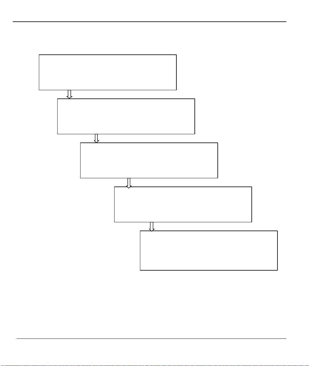
General Structure of this Manual
Getting Started (Chapters 1-2)
This helps you connect, install and setup your Prestige to
The Internet (Chapter 3)
This shows you how to configure your Prestige for
Advanced Applications (Chapters 4-8)
This shows how to use your Prestige for applications
Management & Maintenance (Chapter 9-15)
This provides information on how to create/apply filters, IP
Policy Routing, how to configure your Prestige using
Troubleshooting (Chapter 16)
This provides information about solving common problems.
Structure of the Manual xxx
Page 31

Prestige 480 Dual BRI ISDN Router
Chapter 1
Getting to Know Your Router
This chapter describes the key features and applications of your Prestige.
1.1 Prestige 480 ISDN Router
The Prestige 480 is a dual-line multi-protocol ISDN router. The Prestige is ideal for everything from Internet
browsing or receiving calls from remote dial-in users to making LAN-to-LAN connections to remote
networks.
1.2 Features of Prestige 480
The following are the key features of the Prestige 480.
Dual ISDN Basic Rate Interface (BRI) Support
The P480 supports two BRI, with each BRI offering two 64Kbps channels. The channels can be used
independently for up to four destinations simultaneously in any incoming/outgoing combination or be
bundled in a single connection to speed up data transfer.
Mega Bundle or Multiple ISPs Support
The P480 can call a second, third or fourth ISP when the traffic exceeds a certain threshold and split the
traffic between the various connections. The P480 refers to this multiple ISPs support as Mega Bundle.
IP Alias
The P480 allows you to partition a physical network into logical networks. It support three logical networks
on the same physical Ethernet segment and allows the users to access the Internet using Prestige's Single
Getting to know your Prestige 1-1
Page 32

Prestige 480 Dual BRI ISDN Router
User Account feature. The ability to partition physical network into logical network over the same Ethernet
interface is referred to as IP Alias functionality.
Dial-in Server
The four B-channels and the dial -in capability make the Prestige an ideal platform as a dial-in server to
provide remote access for up to four telecommuting employees.
Auto-negotiating 10/100 Mbps Ethernet
The LAN interface automatically detects if it’s on a 10 or a 100 Mbps Ethernet and adjusts itself for the
highest speed.
Single User Account (SUA)
The SUA™ (Single User Account) features allows multiple users on the LAN to share Internet access for the
price of a single ISP account.
DNS Proxy
The DNS (Domain Name System) proxy capability eliminates the need of statically configuring the DNS
servers.
DHCP Support
DHCP (Dynamic Host Configuration Protocol) server/relay support allows the workstations on your LAN to
obtain the configuration from the Prestige.
Dial-On-Demand
The Dial-On-Demand feature allows the Prestige to automatically place a call to a remote gateway based on
the triggering packet’s destination without user intervention.
Multiple Protocol Support
♦ TCP/IP (Transmission Control Protocol/Internet Protocol) network layer protocol.
♦ IPX (Internetwork Packet eXchange) network layer protocol.
♦ Transparent bridging for unsupported network layer protocols.
1-2 Getting to know your Prestige
Page 33

Prestige 480 Dual BRI ISDN Router
IP Policy Routing Support
The Prestige can now override the default routing behavior and forward packets based on the policies defined
by the network administrator.
PPP Support
The Prestige supports PPP (Point-to-Point Protocol) link layer protocol.
PPP Multilink Support
The Prestige can bundle up to four B-channels in a single connection using the PPP Multilink Protocol The
number of links can be either statically configured or dynamically managed based on traffic demand.
Bandwidth-On-Demand
The Prestige can dynamically allocate bandwidth by adding and dropping links according to traffic demand.
The telephone number of an additional link can be obtained either with BAP (Bandwidth Allocation
Protocol) or statically configured.
Full Network Management
♦ Windows based PNC (Prestige Network Commander).
♦ SNMP (Simple Network Management Protocol) support.
♦ SMT (System Management Terminal) access through telnet connection.
PNC
The Prestige Network Commander (PNC) is a C++ based utility designed to allow users to access the
Prestige’s management settings via Windows. For configuring your Prestige with PNC, use PNC ISDN
Series Version 2.20.
SNMP
The Simple Network Management Protocol (SNMP) is a management protocol for collecting information
from devices on the network. When TCP/IP is configured in your Prestige, the SNMP agent functionality
allows a manager station to manage and monitor the Prestige through the network.
Getting to know your Prestige 1-3
Page 34

Prestige 480 Dual BRI ISDN Router
SMT
The System Management Terminal (SMT) is a menu-driven interface to configure your Prestige using either
console port (through RS232 cable) connection or telnet (through LAN) connection. You can access the SMT
from either a VT100 compatible terminal or a terminal emulation program on a computer.
Logging and Tracing
♦ CDR (Call Detail Record) for assistance in analyzing and managing the telephone bill.
♦ Built-in message logging and packet tracing.
♦ UNIX syslog facility support.
RADIUS Support
RADIUS (Remote Authentication Dial-In User Service) is the most popular protocol for user authentication
on dial -up lines. RADIUS support allows you to use an external server for unlimited number of users and
helps in the centralized management of the users database.
PAP and CHAP Security
The Prestige supports PAP (Password Authentication Protocol) and CHAP (Challenge Handshake
Authentication Protocol). CHAP is more secure than PAP; however, PAP is readily available on more
platforms.
CLID Support
CLID (Calling Line Identification) allows the Prestige to authenticate the caller before a call is answered,
thus saving the cost of a connection. The Prestige uses the caller ID in call setup message to match against
the CLID in database. (Note: The telephone company must support Caller ID for CLID authentication to
work on the Prestige.)
Call Back
The Callback feature allows the Prestige to disconnect a call and then call back when an authorized remote
user dials into the system. This prevents intruders from accessing your network and makes accounting easier
when you use the Prestige as a dial -in server.
1-4 Getting to know your Prestige
Page 35

Prestige 480 Dual BRI ISDN Router
Packet Filtering
The Prestige supports packet filtering that stops leakage of private data to the outside world and controls
access to undesirable locations.
Call Control
Your Prestige provides budget management for outgoing calls and maintains a blacklist for unreachable
phone numbers, thus saving you the expense of unnecessary charges.
Data Compression
Your Prestige incorporates Stac data compression to speed up data transfer. Stac is the de facto standard of
data compression over PPP links.
Networking Compatibility
Your Prestige is compatible with remote access products from other manufacturers such as Ascend, Cisco,
and 3Com. Furthermore, it supports Microsoft Windows 95 and Windows NT dial-up networking (DUN)
capability.
Firmware Upgrade
In addition to the direct console port connection, the Prestige supports the uploading of firmware and the
configuration file using FTP (File Transfer Protocol) and TFTP (Trivial File Transfer Protocol). TFTP over
the WAN is not recommended because of potential data corruption problems.
Backup and Restore Configuration File
You can backup the configuration of the Prestige to your workstation and also restore the configuration from
your workstation using direct console port connection, FTP and TFTP.
1.3 Applications for Prestige 480
The following sections show you the possible applications for your Prestige.
Getting to know your Prestige 1-5
Page 36

Prestige 480 Dual BRI ISDN Router
1.3.1 Internet Access
The Prestige is the ideal high-speed Internet access solution. Your Prestige supports the TCP/IP protocol that
the Internet uses exclusively. It is also compatible with access servers manufactured by major vendors such
as Cisco and Ascend. A typical Internet Access application is shown next.
Figure 1-1 Internet Access Application
Internet Single User Account
For a SOHO (Small Office/Home Office) environment, your Prestige offers a Single User Account (SUA)
feature that allows multiple users on the LAN (Local Area Network) to access the Internet concurrently for
1-6 Getting to know your Prestige
Page 37
Prestige 480 Dual BRI ISDN Router
the cost of a single account. Single User Account address mapping can also be used for other LAN to LAN
connections.
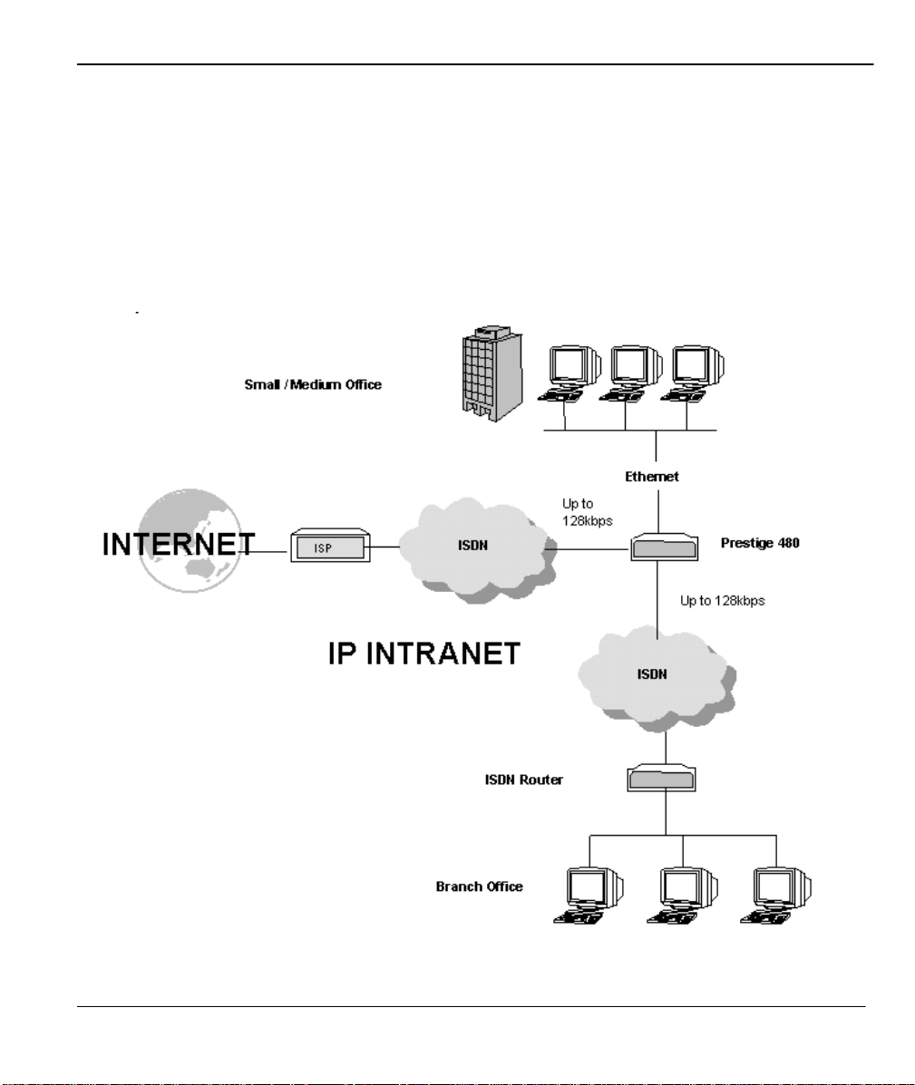
Intranet Application
Small/Medium Office users can access the Internet via one ISDN BRI at speed up to 128Kbps even when the
branch office users are connected remotely. The branch office users can access the Internet without extra ISP
subscription fee. The application is shown next in Figure 1.2 Internet Access Application.
Getting to know your Prestige 1-7
Page 38

Prestige 480 Dual BRI ISDN Router
Figure 1-2 Internet Access Application
1-8 Getting to know your Prestige
Page 39
Prestige 480 Dual BRI ISDN Router
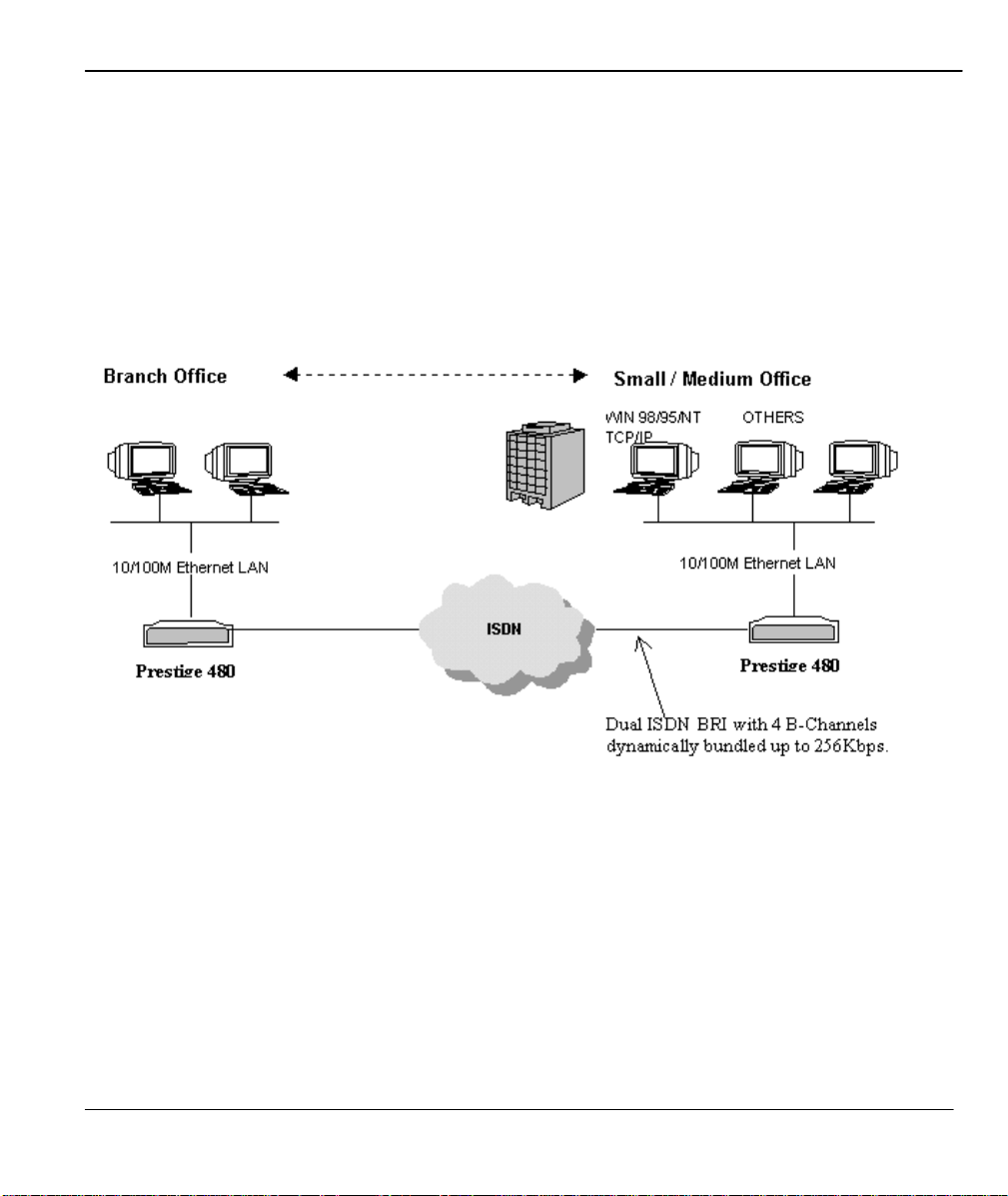
1.3.2 LAN-to-LAN Connection
You can use the Prestige to connect two geographically dispersed networks at speeds of up to 256Kbps over
two ISDN BRI lines. It incorporates PPP/MP (Point-to-Point Protocol/Multilink Protocol ) to bundle the B
channels. The Prestige supports TCP/IP protocols. A typical LAN -to-LAN application for your Prestige is
shown next.
Figure 1-3 LAN-to-LAN Application
Getting to know your Prestige 1-9
Page 40

Prestige 480 Dual BRI ISDN Router
1.3.3 Remote Access Server
Your Prestige allows remote users to dial in and gain access to your LAN. This feature enables users that
have workstations with remote access capabilities, e.g., Windows 95, to dial in to access the network
resources without physically being in the office. Either PAP (Password Authentication Protocol) or CHAP
(Challenge Handshake Authentication Protocol) authentication can be used to control the access from the
remote users. You can also use callback for security and/or accounting purposes.
Figure 1-4 Remote Access Server Application
1-10 Getting to know your Prestige
Page 41
Prestige 480 Dual BRI ISDN Router
Chapter 2
Hardware Installation & Initial Setup
This chapter shows you how to make the cable connections to your Prestige as
well as set up your ISDN connection using the SMT.
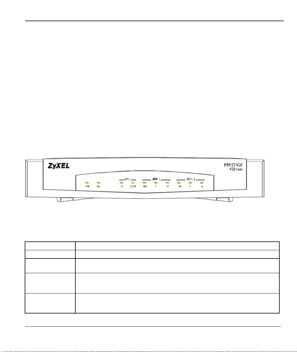
2.1 Front Panel LEDs
The LED indicators on the front panel indicate the router functional status of the Prestige. The following
table describes the LED functions:
Figure 2-1 Front Panel
Table 2-1 LED Functions
Field Description
PWR The PWR (power) LED is on when power is applied to the Prestige.
SYS The SYS (System) LED is on when the system is running normally, and off when the
system is not ready or failed. It flashes when the system is rebooting.
LAN 10M This green LED is on when the 10M Ethernet is connected and ready and off when
100M This orange LED is on when the 100M Ethernet is connected and ready and off
Hardware Installation and Setup 2-1
the 10M Ethernet is not ready or failed. This LED flashes when the Prestige is
sending or receiving packets.
when the 100M Ethernet is not ready or failed. This LED flashes when the Prestige
is sending or receiving packets.
Page 42
Prestige 480 Dual BRI ISDN Router
SMT Management
LAN
Field Description
ISDN 1 & 2 LNK
B1/B2
The LNK (Link) LED is on when the Prest ige is connected to an ISDN switch and
the line has been successfully initialized; otherwise, it is off.
The B1/B2 LED is on when the corresponding B Channel is in use.
ISDN 2
Power
ISDN 1
Power
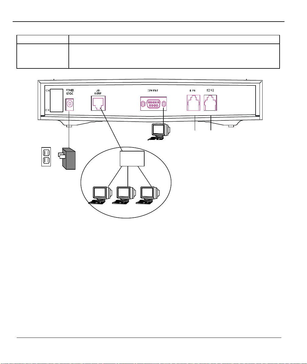
2.2 Prestige 480 Rear Panel and Connections
This section outlines how to connect your Prestige 480 to the LAN and to the ISDN network.
The figure below shows the rear panel of your Prestige 480 and the connection diagram.
Figure 2-2 Prestige 480 Rear Panel and Connections
2-2 Hardware Installation and Setup
Page 43

Prestige 480 Dual BRI ISDN Router
Step 1. Connecting the ISDN lines
Connect the Prestige to the ISDN network using the included ISDN (black) cable. Plug one end of the cable
into the port labeled ISDN BRI and the other to the ISDN wall jack.
Step 2. Connecting Ethernet to your Prestige
Use a Unshielded Twisted Pair (UTP) cable and RJ-45 connectors that look like a bigger telephone plug
with eight pins to connect your Prestige to a 10/100M LAN.
Warning: Please verify the correct cable before connecting. If one of these cables is accidentally
used to connect your Prestige to the ISDN lines, it may damage your Prestige.
Step 3. Connecting the Power Adapter to your Prestige
Connect the power adapter to the port labeled POWER on the rear panel of your Prestige.
Step 4. Connecting the Console Port
For the initial configuration of your Prestige, you need to use a terminal emulator software on a workstation
and connect it to the Prestige through the console port. Connect the 9-pin (smaller) end of the console cable
to the console port of the Prestige and the 25-pin (bigger) end to a serial port (COM1, COM2 or other COM
port) of your workstation. You can use an extension RS-232 cable if the enclosed one is too short.
After the initial setup, you can also modify the configuration remotely through telnet connections. See the
chapter Telnet Configuration and Capabilities for detailed instructions on using telnet to configure your
Prestige.
2.3 Prestige Network Commander
You can also setup the Prestige using the Prestige Network Commander (PNC). The PNC is a Windowsbased tool that provides a quick and simple way to configure your Prestige. For more information on
installing PNC insert the PNC installation disc in the relevant drive of your computer and follow the onscreen directions.
Hardware Installation and Setup 2-3
Page 44

Prestige 480 Dual BRI ISDN Router
(2) DSS1:
Note: You cannot access the PNC if you use the RS232 cable. You must use only the Ethernet cable.
2.4 Additional Installation Requirements
In addition to the contents of your package, there are other hardware and software requirements you need
before you can install and use your Prestige. These requirements include:
1. A computer with Ethernet 10Base-T NIC (Network Interface Card).
2. A computer equipped with communications software configured to the following parameters:
♦ VT100 terminal emulation.
♦ 9600 Ba ud.
♦ No parity, 8 Data bits, 1 Stop bit.
2.5 Housing
Your Prestige's housing has ventilation slots for cooling and clip-out legs that fit snugly into grooves for
sturdy stacking with better airflow. ZyXEL recommends that you do not stack more than 4 routers for
maximum stack stability and cooling.
2.6 Power On Your Prestige
At this point, you should have connected the console port, the ISDN BRI port, the Ethernet port and the
power port to the appropriate devices or lines.
Step 1. Initial Screen
When you power on your Prestige, it performs several internal tests as well as line initialization. After the
initialization, the Prestige asks you to press [Enter] to continue, as shown.
Copyright (c) 1994 - 1999 ZyXEL Communications Corp.
initialize ch =0, ethernet address: 00:a0:c5:ff:00:35
(2) DSS1:
2-4 Hardware Installation and Setup
Page 45

Prestige 480 Dual BRI ISDN Router
Figure 2-3 Power-On Display
Step 2. Entering Password
The login screen appears after you press [Enter], prompting you to enter the password, as shown next.
For your first login, enter the default password 1234. As you type the password, the screen displays a (X)
Enter Password : XXXX
for each character you type.
Figure 2-4 Login Screen
Please note that if there is no activity for longer than 5 minutes after you log in, your Prestige will
automatically log you out and will display a blank screen. If you see a blank screen, press [Enter] to bring
up the login screen again.
2.7 Navigating the SMT Interface
The SMT (System Management Terminal) is the interface that you use to configure your Prestige.
Several operations that you should be famili ar with before you attempt to modify the configuration are listed
in the table below.
Table 2-2 Main Menu Commands
Operation Press/<read> Description
Move forward to
another menu
Move backward to
a previous menu
Move to a submenu Press the [Space
Hardware Installation and Setup 2-5
[Enter] To move forward to a sub-menu, type in the number of the
desired sub-menu and press [Enter].
[Esc] Press the [Esc] key to move back to the previous menu.
bar] to change NO
Fields beginning with “Edit” have a default setting of No. Press
the [Space bar] to change No to Yes, then press [ENTER] to go
Page 46

Prestige 480 Dual BRI ISDN Router
You need to fill in two types of fields. The first requires you to type
Operation Press/<read> Description
to YES then press
[ENTER].
Move the cursor [Enter] or
[Up]/[Down] arrow
keys
Enter information Fill in, or
Press the [Space
bar] to toggle
Required fields
N/A fields <N/A> Some of the fields in the SMT will show a <N/A>. This symbol
Save your
configuration
Exit the SMT Type 99, then
<?>
[Enter] Save your configuration by pressing [Enter] at the message
press [Enter].
to a submenu.
Within a menu, press [Enter] to move to the next field. You can
also use the [Up]/[Down] arrow keys to move to the previous and
the next field, respectively.
in the appropriate information. The second allows you to cycle
through the available choices by pressing the [Space] bar.
All fields with the symbol <?> must be filled in order be able to
save the new configuration.
refers to an option that is Not Applicable.
[Press ENTER to confirm or ESC to cancel]. Saving the data on
the screen will take you, in most cases to the previous menu.
Type 99 at the Main Menu prompt and press [Enter] to exit the
SMT interface.
After you enter the password, the SMT displays the Main Menu, as shown next.
2-6 Hardware Installation and Setup
Page 47

Prestige 480 Dual BRI ISDN Router
Copyright (c) 1994
–
1999
ZyXEL Communications Corp.
Getting Started
1. General Setup
2. ISDN Setup
3. Ethernet Setup
4. Internet Access Setup
Advanced Applications
11. Remote Node Setup
12. Static Routing Setup
13. Defau lt Dial-in Setup
14. Dial-in User Setup
15. SUA Server Setup
Prestige 480 Main Menu
Enter Menu Selection Number:
Advanced Management
21. Filter Set Configuration
22. SNMP Configuration
23. System Security
24. System Maintenance
25. IP Policy Routing
99. Exit
Figure 2-5 SMT Main Menu
2.7.1 System Management Terminal Interface Summary
Table 2-3 Main Menu Summary
# Menu Title Description
1 General Setup Use this menu to setup general information.
2 ISDN Setup Use this menu to setup the ISDN.
3 Ethernet Setup Use this menu to setup Ethernet.
4 Internet Access Setup A quick and easy way to setup Internet connection.
11 Remote Node Setup Use this menu to setup the Remote Node for LAN-to-LAN connection,
12 Static Routing Setup Use this menu to setup static route for different protocols.
13 Default Dial-in Setup Use this menu to setup default dial-in parameters so that your Prestige
14 Dial-in User Setup Use this menu to setup dial-in users.
15 SUA Server Setup
21 Filter Set Configuration Use this menu to setup filters to provide security, call control, et c.
22 SNMP Configuration Use this menu to setup SNMP related parameters.
23 System Security Use this menu to setup security related parameters.
including Internet connection.
can be used as a dial-in server.
Use this menu to specify inside servers when SUA is enabled.
Hardware Installation and Setup 2-7
Page 48

Prestige 480 Dual BRI ISDN Router
Menu 23
-
System Security
24 System Maintenance This menu provides system status, diagnostics, firmware upload, etc.
25 IP Policy Rout ing This menu allows you to configure Routing Policies,
99 Exit To exit from SMT and return to the blank screen.
2.8 Changing the System Password
The first thing your should do before anything else is to change the default system password by following the
steps below .
Step 1. Enter 23 in the Main Menu to open Menu 23 - System Security as shown next.
1. Change Password
2. External Server
Enter Menu Selection Number:
Figure 2-6 Menu 23 - System Security
Step 2. Enter 1 in Menu 23 to open Menu 23.1 - System Security – Change P assword.
2-8 Hardware Installation and Setup
Page 49

Prestige 480 Dual BRI ISDN Router
Menu 23.1
–
System Security
-
Change Password
When the Menu 23.1- System Security-Change Password appears, as shown in the next figure , type in
your existing default system password, i.e., 1234, and press [Enter].
Old Password= ?
New Password= ?
Retype to confirm= ?
Enter here to CONFIRM or ESC to CANCEL:
Figure 2-7 Menu 23.1 - System Security - Change Password
Step 3. Enter your new system password and press [Enter].
Step 4. Re-type your new system password for confirmation and press [Enter].
Note that as you type a password, the screen displays an (*) for each character you type.
2.9 Resetting the Pre stige
If you have forgotten your password or for some reason cannot access the SMT menu you will need to
reinstall the configuration file. Uploading the configuration file replaces the current configuration file
with the def ault configuration file. This means that you will lose all configurations that you had before
and the speed of the console port will be reset to the default of 9600 bps with 8 data bit, no parity and 1
stop bit (8n1). The password will be reset to the default of 1234, also.
Download the "romfile.zip" file from the Internet, unzip it and save it in a folder. Turn off the Prestige and
begin a Telnet session with the default console port settings.
Hardware Installation and Setup 2-9
Page 50

Prestige 480 Dual BRI ISDN Router
Turn on the Prestige again. You should see the following screen.
Bootbase Version: V1.10 | 6/11/1999 15:04:51
RAM: Size = 8192 Kbytes
DRAM POST: Testing: 8192k OK
FLASH: intel 8M* 2
ZyNOS Version: V2.40(o.00)b02/ 7/13/1999 15:37:32
Press any key to enter debug mode within 3 seconds.
........................................
Figure 2-8 Booting Up the Prestige
When you see the message "Press Any key to enter Debug Mode within 3 seconds", press any key to
enter debug mode. Follow the procedure below to upload the configuration file:
1. Enter “atur3” after the “Enter Debug Mode ” message.
2. Wait for the “Starting XMODEM upload” message before activating Xmodem upload on
your terminal.
3. After successful firmware upload, enter “atgo” to restart the Prestige.
The Prestige is now reinitialized with default configuration file including the default password of 1234.
NOTE:
The configuration filename is the router model name with a rom extension, e.g., p480.rom. The ZyNOS
firmware filename is the router model name with a bin extension, e.g., p480.bin. Rename the latter
filename to “ras” when uploading to the Prestige via FTP or TFTP.
2-10 Hardware Installation and Setup
Page 51

Prestige 480 Dual BRI ISDN Router
Hardware Installation and Setup 2-11
Page 52

Prestige 480 Dual BRI ISDN Router
Contact Person's
Menu 1
-
General Setup
2.10 General Setup
Menu 1 - General Setup contains administrative and system -related information.
To enter Menu 1 and fill in the required information, follow these steps:
Step 1. Enter 1 in the Main Menu to open Menu 1 – General Setup.
Step 2. The Menu 1 - General Setup screen appears, as shown next. Fill in the required fields marked [?]
as explained in the following table.
System Name= ?
Location=
Contact Person's Name=
Press ENTER to Confirm or ESC to Cancel:
Figure 2-9 Menu 1 – General Setup
Table 2-4 General Setup Menu Fields
Field Description Example
System Name Choose a descriptive name for identification purposes. This name
can be up to 8 alphanumeric characters long. Spaces are not
allowed, but dashes “-” and underscores "_" are accepted. This
name can be retrieved remotely via SNMP, used for CHAP
authentication, and will be displayed at the prompt in the
Command Mode.
Location
(optional)
Enter the geographic location (up to 31 characters) of your
Prestige.
Enter the name (up to 30 characters) of the person in charge of
Name (optional)
this Prestige.
P480
MyHouse
JohnDoe
2-12 Hardware Installation and Setup
Page 53

Prestige 480 Dual BRI ISDN Router
Menu 2
-
ISDN Setup
Menu 2.1
-
ISDN Basic Setup
ISDN Line= 1
Press ENTER to Confirm or ESC to Cancel:
Press Space Bar to Toggle.
2.11 European ISDN Setup Menus
Menu 2 is for you to enter the information about your ISDN lines. Please note that the Prestige only accepts
digits in phone number fields; please do not include ‘-‘ or spaces in these fields.
1. ISDN Line 1 Setup
2. ISDN Line 2 Setup
3. NetCAPI Setup
Enter Menu Selection Number:
Figure 2-10 Menu 2 – ISDN Setup
From Menu 2 select 1 or 2 to display Menu 2.1 - ISDN Basic Setup.
Switch Type: DSS-1
B Channel Usage= Switch/Switch
Incoming Phone Numbers:
ISDN Data =
Edit Advanced Setup = No
Figure 2-11 Menu 2.1 – ISDN Basic Setup
Hardware Installation and Setup 2-13
Page 54

Prestige 480 Dual BRI ISDN Router
Menu
2.1.1
-
ISDN Advanced Setup
Table 2-5 Menu 2.1 – ISDN Basic Setup
Field Description.
ISDN Line Refers to ISDN line 1 or line 2 setup that you selected in Menu 2 - ISDN Setup
Switch Type This field is fixed as DSS-1 for European switches.
B Channel Usage
In general, this will be Switch/Switch (the default). If you are only using one B
channel (e.g., your Prestige is sharing the ISDN BRI line with another device),
then select Switch/Unused. If your second B channel is a leased line, select
Switch/Leased. Press the [Space bar] to toggle through all the options. These
options are
Incoming Phone
Switch/Switch
Switch/Leased
Leased/Switch
Determines how incoming calls are routed.
Leased/Unused
Unused/Leased
Leased/Leased
Switch/Unused
Number Matching
ISDN Data Enter the telephone number assigned to ISDN data call s for the Prestige. The
maximum number of digits is 25 for the telephone number.
Edit Advanced Setup Select Yes and press [Enter] to go to the advanced setup submenu. See below.
2.11.1 Advanced Setup
Select Yes in the Advanced Setup field of Menu 2.1 – ISDN Basic Setup to display Menu 2.1.1.
ISDN Line= 1
Calling Line Indication= Enable
PABX Outside Line Prefix=
PABX Number (Include S/T Bus Number) for Loopback=
Outgoing Calling Party Number:
ISDN Data =
Press ENTER to Confirm or ESC to Cancel:
Press Space Bar to Toggle.
2-14 Hardware Installation and Setup
Page 55

Prestige 480 Dual BRI ISDN Router
Figure 2-12 Menu 2.1.1 - ISDN Advanced Setup
Hardware Installation and Setup 2-15
Page 56

Prestige 480 Dual BRI ISDN Router
Table 2-6 Menu 2.1.1 - ISDN Advanced Setup
Field Description
Calling Line Indication The Calling Line Indication, or Caller ID, governs whether the other party can
see your number when you call. If set to Enable, the Prestige sends the caller
ID and the party you call can see your number; if it is set to Disable, the caller
ID is blocked.
PABX Outside Line Prefix A PABX (Private Automatic Branch eXchange) generally requires you to dial a
number (a single digit in most cases) when you need an outside line. If your
Prestige is connected to a PABX, enter this number in PABX Outside Line
Prefix, otherwise, leave it blank. Please note that the PABX prefix is for calls
initiated by the Prestige only.
PABX Number (Include
S/T Bus Number)
Outgoing Calling Party
Number
ISDN Data If this field is not blank, the Prestige will use its value as the calling party
The PABX number is used for an outside loopback test when the ISDN PABX
cannot support a local loopback test. If the Prestige is connected to an ISDN
PABX enter this number. Note that this number is used exclusively for
loopback testing; for regular outgoing calls, the Prestige dials the phone
number in the remote node. If this field is blank it indicates either that the
PABX supports local loopback testing or that the Prestige is not connected to a
PABX.
number for "ISDN Data" outgoing calls. Otherwise, the individual entry for
"ISDN Data" in Menu 2.1 will be used as the calling party number. You only
need to fill in this field if your switch or PABX requires a specific calling party
number for outgoing calls; otherwise, leave it blank.
When you are finished, press [Enter] at the message: ‘Press [Enter] to confirm’, the Prestige uses the
information that you entered to initialize the ISDN lines. It should be noted that whenever the switch type is
changed, the ISDN initialization takes slightly longer.
At this point, the Prestige asks if you wish to test your ISDN. If you select Yes, the Prestige will perform a
loop-back test to check the ISDN lines. If the loop-back test fails, please note the error message that you
receive and take the appropriate troubleshooting action.
2-16 Hardware Installation and Setup
Page 57

Prestige 480 Dual BRI ISDN Router
Setup LoopBack Test...
Dialing to 40000 ...
Sending and Receiving Data ...
Disconnecting...
Figure 2-13 Loopback Test
2.12 NetCAPI Setup
2.12.1 Basics
NetCAPI is ZyXEL's implementation of CAPI (Common ISDN Application Program Interface) capabilities
over a network. It runs over DCP (Device Control Protocol) developed by RVS-COM.
NetCAPI can be used for applications such as Eurofile transfer, file transfer, G3/G4 Fax, Autoanswer host
mode, telephony, etc. on Windows 95/98/NT platforms.
2.12.2 CAPI
CAPI is an interface standard that allows applications to access ISDN services. Several applications can
share one or more ISDN lines. When an application wants to communicate with an ISDN terminal it sends a
series of standard commands to the terminal. The CAPI standard defines the commands and allows you to
use a well-defined mechanism for communications using ISDN lines.
CAPI also simplifies the development of ISDN applications through many default values that do not
need to be programmed. It provides a unified interface for applications to access the different ISDN services
such as data, voice, fax, telephony, etc.
2.12.3 ISDN-DCP
ISDN-DCP allows a workstation on the LAN to use services such as transmitting and receiving faxes as well
as placing and receiving phone calls.
Hardware Installation and Setup 2-17
Page 58

Prestige 480 Dual BRI ISDN Router
NetCAPI
CAPI Driver
RVS-COM Lite
Using ISDN-DCP, the Prestige acts as a DCP server. By default, the Prestige listens for DCP
messages on TCP port number 2578 (the Internet-assigned number for RVS-COM DCP). When the Prestige
receives a DCP message from a DCP client i.e., a workstation, the Prestige processes the message and acts on
it. Your Prestige supports all the DCP messages specified in the ISDN -DCP specification.
2.12.4 RVS-COM
RVS-COM includes an ISDN CAPI driver with its communication program. RVS-CE (Core
Engine) is an ISDN -CAPI 2.0 driver for Windows 95/98/NT that can be used by different ISDN
communication programs (such as AVM Fritz or RVS-COM) to access the ISDN on the Prestige.
NetCAPI can carry out CAPI applications only if the CAPI driver is installed on your workstation.
In addition to the CAPI driver, you will need a communication software program such as RVS-COM Lite,
Fritz etc., for users to access CAPI.
The ISDN router is a shared device and can be used by several different client workstations at the
same time: e.g. one workstation sending a fax, another workstation doing a file transfer. RVS-COM has to be
installed on each client workstation in order to share the ISDN lines.
2.13 Configuring the P480 as a NetCAPI Server
This section describes how to configure your Prestige to be a NetCAPI server using the SMT (System
Management Terminal).
[Note: For configuring your Prestige with the PNC, use PNC ISDN Series version 2.20 or above.]
By default, NetCAPI is enabled on your Prestige. When NetCAPI is enabled, the Prestige listens for
incoming DCP messages from the workstations. By default, the Prestige listens for DCP messages on TCP
port 2578.
The following figure illustrates the configuration.
2-18 Hardware Installation and Setup
Prestige
Page 59

Prestige 480 Dual BRI ISDN Router
Figure 2-14 Configuration Example
Before entering any configurations, you must install the CAPI driver (RVS-CE) and communication program
such as RVS-COM Lite on your workstation.
2.13.1 Installing the CAPI driver and Communication Software
[Note: Please uninstall previous versions of "RVS-CAPI" and "RVS-COM lite" before you install the new
versions. You may use the Windows "START | Settings | Control Panel | Add/Remove Programs" to uninstall
RVS-CAPI and RVS-COM.]
To install the CAPI driver and the communication software, enter one of the license keys of your RVS-COM
Lite CD -ROM and follow the instructions on the configuration wizard. When you install RVS-Lite, RVSCOM AUTOMATICALLY instal ls CAPI driver before installing RVS-Lite.
Note: If you did not install RVS-Lite and want to use other programs such as AVM Fritz to access the ISDN
router, you must first install the CAPI driver - RVS -CE using the English version installation wizard (in
\DISKs\CEPE\ DISK1\) and start the SETUP.EXE.
2.13.2 Configuring NetCAPI
Step 1. Go to Menu 2.3 - NetCAPI Setup .
Menu 2.3 - NetCAPI Setup
Active= Yes
Max Number of Registered Users= 1
Incoming Data Call Number Matching= MSN
Access List:
Start IP End IP Operation
192.168.1.132 192.168.1.145 Both
192.168.14.1 192.1 68.14.32 Imcoming
Hardware Installation and Setup 2-19
Page 60

Prestige 480 Dual BRI ISDN Router
Figure 2-15 Menu 2.2 - NetCAPI Setup
Step 2. Set the fields in the above menu according to the following description.
Table 2-7 NetCAPI Setup Fields
Field Description
Active This field allows you to enable or disable NetCAPI. Press the [Spacebar] to toggle
between Yes and No
Max Number of
Registered Users
Incoming Data
Call Matching
When you want to use NetCAPI to place outgoing calls or to listen to incoming calls,
you must start RVSCOM on your workstation, and RVSCOM will register itself to the
Prestige. This option is the maximum number of clients that the Prestige supports at the
same time. The default value is 4.
This field determines how incoming calls are routed. Press the [Spacebar] to select
NetCAPI if you want to direct all incoming data calls to NetCAPI.
Select MSN if you want to direct all incoming call to the Prestige only when the
incoming phone number matches the ISDN DATA number in Menu 2. If the incoming
phone number does not match the ISDN DATA number, then the call will be routed to
NetCAPI.
Select Called Party Subaddress if you want to direct all incoming calls to the Prestige
only when the incoming call matches the subaddress of ISDN DATA in Menu 2. If the
incoming call does not match the subaddress of ISDN DATA, then the call will be routed
to NetCAPI.
Access List This list specifies users that can use NetCAPI. This access list controls if a client is
Start IP Refers to the first IP address of a group of NetCAPI clients. Each group contains
End IP Refers to the last IP address in a NetCAPI client group.
Operation Press the [Spacebar] to select Incoming if you wish to grant incoming calls permission.
allowed to use NetCAPI. The request is rejected when
1. The IP address of the workstation is not between Start IP and End IP or
2. The request from the workstation is not permi tted as specified in the
Operation field.
contiguous IP addresses.
Select Outgoing if you wish to grant outgoing calls permission. Select
Both if you wish to grant both incoming calls and outgoing calls permissions. Select
None if you wish to deny all calls.
2-20 Hardware Installation and Setup
Page 61

Prestige 480 Dual BRI ISDN Router
Hardware Installation and Setup 2-21
Page 62

Prestige 480 Dual BRI ISDN Router
Menu 3
-
Ethernet Set
up
Menu 3.1
-
General Ethernet Setup
2.14 Ethernet Setup
This section describes how to configure the Ethernet using Menu 3 – Ethernet Setup. From the Main
Menu, enter 3 to open Menu 3.
1. General Setup
2. TCP/IP and DHCP Setup
Enter Menu Selection Number:
Figure 2-16 Menu 3 - Ethernet Setup
2.14.1 General Ethernet Setup
This menu allows you to specify the filter sets that you wish to apply to the Ethernet traffic. You seldom
need to filter Ethernet traffic, however, the filter sets may be useful to block certain packets, reduce traffic
Input Filter Sets:
protocol filters= 2
device filters=
Output Filter Sets:
protocol filters=
device filters=
Press ENTER to Confirm or ESC to Cancel:
and prevent security breaches.
2-22 Hardware Installation and Setup
Page 63

Prestige 480 Dual BRI ISDN Router
Figure 2-17 General Ethernet Setup
If you need to define filters, please read Chapter 9 - Filter Set Configuration, then return to this menu to
define the filter sets.
Hardware Installation and Setup 2-23
Page 64

Page 65

Prestige 480 Dual BRI ISDN Router
Menu 1
-
General Setup
Chapter 3
Internet Access
This chapter shows you how to configure the LAN as well as the WAN of your
Prestige for Internet access.
3.1 Factory Ethernet Defaults
The Ethernet parameters of the Prestige are preset in the factory with the following values:
1. IP address of 192.168.1.1 with subnet mask of 255.255.255.0 (24 bits).
2. DHCP server enabled with 32 client IP addresses starting from 192.168.1.33.
These parameters should work for the majority of installations. If the parameters are satisfactory, you can
skip to section 3.4 TCP/IP Ethernet Setup and DHCP to enter the DNS server address(es) if your ISP gives
you explicit DNS server address(es). If you wish to change the factory defaults or to learn more about
TCP/IP, please read on.
3.2 Route IP Setup
The first step is to enable the IP routing in Menu 1 - General Setup.
Internet Access 3-1
System Name= ?
Location=
Contact Person's Name=
Press ENTER to Confirm or ESC to Cancel:
Page 66

Prestige 480 Dual BRI ISDN Router
Figure 3-1 General Setup
To edit Menu 1, enter 1 in the Main Menu to select General Setup and press [Enter].
3.3 TCP/IP Parameters
3.3.1 IP Address and Subnet Mask
Similar to the houses on a street that share a common street name, the machines on a LAN share one
common network number, also.
Where you obtain your network number depends on your particular situation. If the ISP or your network
administrator assigns you a block of registered IP addresses, follow their instructions in selecting the IP
addresses and the subnet mask.
If the ISP did not explicitly give you an IP network number, then most likely you have a single user account
and the ISP will assign you a dynamic IP address when the connection is established. If this is the case, it is
recommended that you select a network number from 192.168.0.0 to 192.168.255.0 (ignoring the trailing
zero) and you must enable the Single User Account feature of the Prestige. The Internet Assigned Number
Authority (IANA) reserved this block of addresses specifically for private use; please do not use any other
number unless you are told otherwise. Let’s say you select 192.168.1.0 as the network number; which covers
254 individual addresses, from 192.168.1.1 to 192.168.1.254 (zero and 255 are reserved). In other words, the
first 3 numbers specify the network number while the last number identifies an individual workstation on that
network.
Once you have decided on the network number, pick an IP address that is easy to remember, e.g.,
192.168.1.1, for your Prestige.
The subnet mask specifies the network number portion of an IP address. Your Prestige will compute the
subnet mask automatically based on the IP address that you entered. You don’t need to change the subnet
mask computed by the Prestige unless you are instructed to do other wise.
3-2 Internet Access
Page 67

Prestige 480 Dual BRI ISDN Router
3.3.2 RIP Setup
RIP (Routing Information Protocol) allows a router to exchange routing information with other routers. The
RIP Direction field controls the sending and receiving of RIP packets. When set to Both, the Prestige will
broadcast its routing table periodically and incorporate the RIP information that it receives; when set to
None, it will not send any RIP packets and will ignore any RIP packets received.
The Version field controls the format and the broadcasting method of the RIP packets that the Prestige sends
(it recognizes both formats when receiving). RIP-1 is universally supported; but RIP-2 carries more
information. RIP-1 is probably adequate for most networks, unless you have a unusual network topology.
Both RIP-2B and RIP-2M sends the routing data in RIP-2 format; the difference being that RIP-2B uses
subnet broadcasting while RIP-2M uses multicasting. Multicasting can reduce the load on non-router
machines since they generally do not listen to the RIP multicast address and so will not receive the RIP
packets. However, if one router uses multicasting, then all routers on your network must use multicasting,
also.
By default, RIP direction is set to Both and the Version set to RIP-1.
3.3.3 DHCP Configuration
DHCP (Dynamic Host Configuration Protocol) allows the individual clients (workstations) to obtain the
TCP/IP configuration at start-up from a centralized DHCP server. The Prestige has built-in DHCP Server
capability, enabled by default, which means it can assign IP addresses, an IP default gateway and DNS
servers to Windows 95, Windows NT and other systems that support the DHCP client. Your Prestige can also
be configured as a Relay. When configured as a relay, the Prestige relays the requests and responses between
the clients and the real DHCP server.
IP Pool Setup
The Prestige is pre-configured with a pool of 32 IP addresses starting from 192.168.1.33 to 192.168.1.64.
This configuration leaves 31 IP addresses (excluding the Prestige itself) in the lower range for other server
machines, e.g., server for mail, FTP, telnet, web, etc., that you may have.
Internet Access 3-3
Page 68

Prestige 480 Dual BRI ISDN Router
DNS Server Address
DNS (Domain Name System) is for mapping a domain name to its corresponding IP address and vice versa,
e.g., the IP address of www.zyxel.com is 204.217.0.2. The DNS server is extremely important because
without it, a user must know the IP address of a machine before s/he can access it. The DNS server addresses
that you enter in the DHCP setup are passed to the client machines along with the assigned IP address and
subnet mask.
There are two ways that an ISP disseminates the DNS server addresses. The first is for an ISP to tell a
customer the DNS server addresses, usually in the form of an information sheet, when s/he signs up. If your
ISP does give you the DNS server addresses, enter them in the DNS Server fields in DHCP Setup .
Some ISP’s choose to pass the DNS servers using the DNS server extensions of PPP IPCP (IP Control
Protocol) after the connection is up. If your ISP did not give you explicit DNS servers, chances are the DNS
servers are conveyed through IPCP negotiation. The Prestige supports the IPCP DNS server extensions
through the DNS proxy feature.
If the Primary and Secondary DNS Server fields in DHCP Setup are not specified, i.e., left as 0.0.0.0, the
Prestige tells the DHCP clients that it itself is the DNS server. When a workstation sends a DNS query to the
Prestige, the Prestige forwards the query to the real DNS server learned through IPCP and relays the response
back to the workstation.
Please note that DNS proxy works only when the ISP uses the IPCP DNS server extensions. It does not
mean you can leave the DNS servers out of the DHCP setup under all circumstances. If your ISP gives you
explicit DNS servers, make sure that you enter their IP addresses in the DHCP Setup menu. This way, the
Prestige can pass the DNS servers to the workstations and the workstations can query the DNS server directly
without the Prestige’s intervention.
Relay Server Address
When the DHCP is set to Relay, the Prestige will request IP addresses from a real DHCP server and relay the
address to the workstation making the request.
3-4 Internet Access
Page 69

Prestige 480 Dual BRI ISDN Router
Menu 3.2
-
TCP/IP and DHCP Ethernet Setup
First address
3.4 TCP/IP Ethernet Setup and DHCP
You will now use Menu 3.2 to configure your Prestige for TCP/IP.
To edit Menu 3.2, select the menu option Ethernet Setup in the Main Menu. When Menu 3 appears, select
the submenu option TCP/IP and DHCP Setup and press [Enter]. The screen now displays Menu 3.2 -
TCP/IP and DHCP Ethernet Setup, as shown next.
in the IP
DHCP Setup
DHCP= Server
Client IP Pool Starting Address= 192.168.1.33
Size of Client IP Pool= 32
Primary DNS Server= 0.0.0.0
Secondary DNS Server= 0.0.0.0
Remote DHCP Server= N/A
TCP/IP Setup:
IP Address= 192.168.1.1
IP Subnet Mask= 255.255.255.0
RIP Direction= Both
Multicast = IGMP-v2
IP Policies=
Edit IP Alias= Yes
Press Space Bar to Toggle.
Version= RIP - 1
Enter here to CONFIRM or ESC to CANCEL:
Size of the
IP addresses
of the DNS
Follow the instructions in the next table on how to configure the DHCP fields.
Internet Access 3-5
Figure 3-2 Menu 3.2 – TCP/IP and DHCP Ethernet Setup
Page 70

Prestige 480 Dual BRI ISDN Router
,
, the DHCP
DNS servers are
Your Prestige will automatically calculate the subnet mask based
Table 3-1 DHCP Ethernet Setup Menu Fields
Field Description Example
DHCP This field enables/disables the DHCP server. If it is set to Server
your Prestige will act as a DHCP server. If set to None
server will be disabled. If set to Relay, the Prestige acts as a
surrogate DHCP server and relays requests and responses
between the remote server and the clients.
When DHCP is used, the following four items need to be set:
Client IP Pool
Starting Address
Size of Client IP
Pool
Primary DNS
Server
Secondary DNS
Server
Remote DHCP
Server
This field specifies the first of the contiguous addresses in the IP
address pool.
This field specifies the size, or count, of the IP address pool. 32
Enter the IP addresses of the DNS servers. The
passed to the DHCP clients along with the IP address and the
subnet mask.
If Relay is selected in the above DHCP= field, then enter the IP
address of the actual, remote DHCP server here.
None
Server (default)
Relay
192.168.1.33
Follow the instructions in the following table to configure TCP/IP parameters for the Ethernet port.
Table 3-2 TCP/IP Ethernet Setup Menu Fields
Field Description Example
IP Address Enter the IP address of your Prestige in dotted decimal notation 192.168.1.1
IP Subnet
Mask
RIP Direction Press the space bar to select the RIP direction from
Version Press the space bar to select the RIP version from RIP-1/RIP-
Multicast Turn on/off IGMP support and select the version fro m IGMP-
IP Policies You can apply up to four IP Policy sets (from twelve) by entering
Edit IP Alias Choose Yes to enter Menu 3.2.1 for configuring second and
on the IP address that you assign. Unless you are implementing
subnetting, use the subnet mask computed by the Prestige
Both/None/In Only/Out Only.
2B/RIP-2M.
v2/IGMP-v1/None.
their numbers separated by commas, e.g., 3, 4,7,12.
255.255.255.0
Both (default)
RIP-1 (default)
IGMP-v2
Yes
3-6 Internet Access
Page 71

Prestige 480 Dual BRI ISDN Router
When you have completed this menu, press [Enter] at the prompt [Press ENTER to Confirm…] to save your
Field Description Example
third IP Alias.
configuration, or press [Esc] at any time to cancel.
3.5 IP Alias
3.5.1 Basics
The P480 supports three logical LAN interface via its single physical Ethernet interface. The Prestige is the
gateway for all the LAN networks. You can also route packets from one network to another. The IP alias
feature allows your Prestige to have extra IP addresses that may be in completely different subnets than the
first IP address. The ability to partition physical network into logical network over the same Ethernet
interface is referred to as IP Alias functionality.
Internet Access 3-7
Ethernet Interface
Prestige
Figure 3-3 Physical Network
Page 72

Prestige 480 Dual BRI ISDN Router
Prestige
LAN 1 IP Address (Menu 3.2)
LAN 2 IP Alias 1 (Menu 3.2.1)
LAN 3 IP Alias 2 (Menu 3.2.1)
Figure 3-4 Partitioned Logical Networks
For example, in a school you can partition the single physical network into administration network, teachers
network and students network as shown next.
Prestige
ADMINISTRATION
TEACHERS
STUDENTS
Figure 3-5 IP Alias Example
3.5.2 IP Alias Setup
3-8 Internet Access
Page 73

Prestige 480 Dual BRI ISDN Router
Menu 3.2
-
TCP/IP and DHCP Ethernet Setup
You must use Menu 3.2 to configure the first network and move the cursor to Edit IP Alias field and toggle
the space bar to choose Yes and press [Enter] to configure the second and third network.
DHCP Setup:
DHCP= None
Client IP Pool Starting Address= N/A
Size of Client IP Pool= N/A
Primary DNS Server= N/A
Secondary DNS Server= N/A
TCP/IP Setup:
IP Address= 192.168.1.1
IP Subnet Mask= 255.255.255.0
RIP Direction= Both
Version= RIP-2B
Multicast = IGMP-v2
IP Policies=
Edit IP Alias= Yes
Press Space Bar to Toggle.
Enter here to Confirm or ESC to Cancel:
Figure 3-6 Menu 3.2 - TCP/IP and DHCP Ethernet Setup
Pressing [Enter] opens Menu 3.2.1 - IP Alias Setup, as shown next.
Menu 3.2.1 - IP Alias Setup
IP Alias 1= No
IP Address= N/A
IP Subnet Mask= N/A
RIP Direction= N/A
Version= N/A
Incoming protocol filters= N/A
Outgoing protocol filters= N/A
IP Alias 2= No
Follow the instructions in the following table to configure IP Alias parameters.
Internet Access 3-9
Figure 3-7 Menu 3.2.1 - IP Alias Setup
Page 74

Prestige 480 Dual BRI ISDN Router
IP Alias Setup Menu Fields
Field Description Example
IP Alias Choose Yes to configure the LAN network for the Prestige. Yes
IP Address Enter the IP address of your Prestige in dotted decimal notation 192.168.2.1
IP Subnet
Mask
RIP Direction Press the space bar to select the RIP direction from Both/In
Version Press the space bar to select the RIP version from RIP-1/RIP-
Your Prestige will automatically calculate the subnet mask based
on the IP address that you assign. Unless you are implementing
subnetting, use the subnet mask computed by the Prestige
Only/Out Only.
2B/RIP-2M.
255.255.255.0
Both
RIP-1
Incoming
Protocol Filters
Outgoing
Protocol Filters
When you have completed this menu, press [Enter] at the prompt [Press ENTER to Confirm…] to save
your configuration, or press [Esc] at any time to cancel.
Enter the filter set(s) you wish to apply to the incoming traffic
between this node and the Prestige.
Enter the filter set(s) you wish to apply to the outgoing traffic
between this node and the Prestige.
3-10 Internet Access
Page 75

Prestige 480 Dual BRI ISDN Router
Menu 4
-
Internet Access Setup
3.6 Internet Access Configuration
Menu 4 allows you to enter the Internet Access information in one screen. Menu 4 is actually a simplified
setup for one of the remote nodes that you can access in Menu 11. Before you configure your Prestige for
Internet access, you need to collect your Internet account information from your ISP. Use the table below to
record your Internet Account Information.
Table 3-3 Internet Account Information
Internet Account Information
IP Address of the ISP's Gateway (Optional)
Write your account
information here
−
Telephone Number(s) of your ISP
Login Name
Password for ISP authentication
DNS server address(es) for your
workstation
−
−
−
−
From the Main Menu, enter option Internet Access Setup to go to Menu 4 - Internet Access Setup, as
displayed next. The table following the figure contains instructions on how to configure your Prestige for
Enter the
ISP's Name= ChangeMe
Pri Phone #= 1234
Sec Phone #=
My L ogin= ChangeMe
My Password= ********
Single User Account= Yes
IP Addr= 0.0.0.0
Telco Options:
Transfer Type= 64K
Multilink= Off
Idle Timeout= 100
Press ENTER to CONFIRM or ESC to CANCEL:
phone
number of
Enter your
login and
password
Internet Access 3-11
Page 76

Prestige 480 Dual BRI ISDN Router
Internet access.
Figure 3-8 Menu 4 – Internet Access Setup
3-12 Internet Access
Page 77

Prestige 480 Dual BRI ISDN Router
Table 3-4 Internet Access Setup Menu Fields
Field Description
ISP’s Name Enter the name of your Internet Service Provider, e.g., myISP. This
information is for identification purposes only.
Pri Phone and Sec Phone
Number
My Login Name Enter the login name given to you by your ISP.
My Password Enter the password associated with the login name above.
Single User Account Please see the following section for a more detailed discussion on the
IP Address If your ISP did not assign you a static IP address, enter [0.0.0.0] here;
Telco options Transfer
Type
Multilink The Prestige uses the PPP Multilane Protocol to bundle multiple links in
Idle Timeout This value specifies the number of idle seconds that elapses before the
Both the Primary and the Secondary Phone number refer to the number
that the Prestige dials to connect to the ISP.
Single User Account feature. The default is Yes.
otherwise, enter that IP address here.
This field specifies the type of connection between the Prestige and this
remote node. Select 64K, or Leased.
a single connection to boost the effective throughput between two nodes.
This option is only available if the transfer type is 64K. See Menu 11.2
for more details.
remote node is automatically disconnected. Idle seconds is the period of
time when no data is transmitted from your Prestige. Administrative
packets such as RIP are not counted as data. The default is 100
seconds. This option only applies when the Prestige initiates the call.
At this point, the SMT will ask if you wish to test the Internet connection. If you select Yes, your Prestige
will call the ISP to test the Internet connection. If the test fails, note the error message that you receive on the
screen and take the appropriate troubleshooting steps.
Internet Access 3-13
Page 78

Prestige 480 Dual BRI ISDN Router
192.168.1.34
192.168.1.36
Prestige 480
3.7 Single User Account
Typically, if there are multiple users on the LAN wanting to concurrently access the Internet, you will have
to lease a block of legal, or globally unique, IP addresses from the ISP.
The Single User Account (SUA) feature allows you to have the same benefits as having m ultiple legal
addresses, but only pay for one IP address, thus saving significantly on the subscription fees. (Check with
your ISP before you enable this feature).
Same Network
192.168.1.33
Number
192.168.1.1
192.168.1.35
ISP
The SUA network appears as a
Figure 3-9 Single User Account Topology
The Single User Account feature may also be used on connections to remote networks other than the ISP.
For example, this feature can be used to simplify the allocation of IP addresses when connecting branch
offices to the corporate network.
3-14 Internet Access
INTERNET
Page 79

Prestige 480 Dual BRI ISDN Router
The IP address for the SUA can be either fixed or dynamically assigned when a call is connected. In addition,
you can designate servers using Menu 15, e.g., a web server and a telnet server, on your local network and
make them accessible to the outside world. For more information on setting up servers see the section
Multiple Servers behind SUA in the chapter Dial-in Server Configuration .
If you do not define any server, SUA offers the additional benefit of firewall protection. If no server is
defined, all incoming inquiries will be filtered out by your Prestige and thus preventing intruders from
probing your network.
Your Prestige accomplishes this address sharing by translating the internal LAN IP addresses to a single
address that is globally unique on the Internet. For more information on IP address translation, refer to RFC
1631, The IP Network Address Translator (NAT).
3.7.1 Advantages of SUA
In summary:
l SUA is a cost-effective solution for small offices with less than 64 hosts to access the Internet or other
remote TCP/I P networks.
l SUA supports servers to be accessible to the outside world.
l SUA can provide firewall protection if you do not specify a server. All incoming inquiries will be
filtered out by your Prestige.
l UDP and TCP packets can be routed. In addition, parti al ICMP, including echo and trace route, is
supported.
Internet Access 3-15
Page 80

Prestige 480 Dual BRI ISDN Router
Menu 4
-
Internet Access Setup
3.7.2 Single User Account Configuration
The steps for configuring your Prestige for Single User Account are identical to the conventional Internet
access with the exception that you need to fill in two extra fields in Menu 4 - Internet Access Setup, as
shown next.
ISP's Name= ChangeMe
Pri Phone #= 1234
Sec Phone #=
My Login= ChangeMe
My Password= ********
Single User Account= Yes
IP Addr= 0.0.0.0
Telco Options:
Transfer Type= 64K
Multilink= Off
Idle Timeout= 100
Enter here to CONFIRM or ESC to CANCEL:
Figure 3-10 Menu 4 – Internet Access Setup for Single User Account
To enable the SUA feature in Menu 4, move the cursor to the Single User Account field and select Yes (or
No to disable SUA). Then follow the instructions on how to configure the SUA fields.
Table 3-5 Single User Account Menu Fields
Field Description
Single User Account Select Yes to enable SUA.
IP Address If your ISP did not assign you a static IP address, enter [0.0.0.0] here; otherwise,
Press [Enter] at the message [Press ENTER to Confirm ...] to save your configurat ion, or press [Esc] at any
time to cancel.
enter that IP address here.
3-16 Internet Access
Page 81

Prestige 480 Dual BRI ISDN Router
At this point, your Prestige will ask if you wish to test the Internet connection. If you select Yes, the Prestige
will call the ISP and test the configuration. If the test fails, note the error messages on the screen and take the
appropriate troubleshooting steps.
3.8 Mega Bundle or Multiple ISPs Support
3.8.1 Basics
If ISPs do not support multilink bundle of more than 2 links, it would be impossible for a user to dedicate all
4 channels available in a P 480 to Internet access. To differentiate P 480 from other similarly equipped
products, it is desirable to be able to support bundle of 4 links where P 480 calls a second ISP when the
traffic exceeds a certain threshold and split the traffic between the two connections. The Prestige refers to
this multiple ISPs support as Mega Bundle.
Mega Bundle design is as listed below.
1. One remote node is designated as the main ISP and another the supplementary ISP. The Prestige dials
the first and second link on the main ISP using the existing mechanism.
2. If a supplementary remote node is specified, BOD behalves as if the maximum number of channels is 4
and the adding and dropping of channels are governed by the main remote node’s multilink parameters
alone.
3. When the traffic triggers the third link (as determined by BOD), the Prestige calls the supplementary
ISP. Since the new connection is a separate PPP session, it will have a different IP address and thus a
new interface.
4. Because of NAT, if an IP connection is already assigned to a particular interface, then it must remain on
that interface. For new connections, the round-robin method is used to assign a connection to either the
main or the supplementary ISP. Non-IP traffic is simply distributed evenly on a packet-by-packet basis.
5. Once the Prestige determines which interface a connection uses, the MP channel assignment within each
bundle remains the same as the existing method.
Internet Access 3-17
Page 82

Prestige 480 Dual BRI ISDN Router
3.8.2 ISP Remote Node and Supplementary Remote Node
The previous ZyNOS versions supported only one ISP account. That remote node is called as the “ISP
remote node”. Now in ZyNOS v2.42, you can setup other ISP accounts and this is called as
“supplementary remote node”.
You can have several “Supplementary remote node”, but only one “ISP remote node”. These remote
nodes can work at the same time. “Supplementary remote” is almost the same as “ISP remote node”
except that “supplementary remote node” will not appear in the routing table as default route.
3.9 Configuring Me ga Bundle
Step 1. Configure an ISP remote node.
1. Setup ISP in Menu 4.
2. Set Multilink= BOD or Multilink= Always in Menu 4
3. In Menu 11, edit the ISP remote node.
Menu 11.2 - Remote Node PPP Options
Encapsulation= Standard PPP
Compression= No
BACP= Enable
Mega Bundle= None
Multiple Link Options:
BOD Calculation= Transmit or Receive
Min. Channels= 1
4. Set Edit PPP Options= Yes and then press [Enter]. You will enter Menu 11.2
3-18 Internet Access
Page 83

Prestige 480 Dual BRI ISDN Router
7. ________
5. In Menu 11.2, set Max. Channels= 3 or Max. Channels= 4
6. Save the configuration.
Step 2. Configure a supplementary remote node.
1. Setup a remote node in Menu 11.
2. Set Edit PPP Options= Yes and then press [Enter]. You will enter Menu 11.2
3. Set Mega Bundle= Supplementary. Return to Menu 11.1.
4. Set Rem IP Addr= 1.2.3.4. The value can be arbitrary IP address except 0.0.0.0 and 1.1.1.1.
5. Set Edit IP/IPX/Bridge= Yes and then press [Enter]. You will enter Menu 11.3.
6. Set Rem Subnet Mask= 0.0.0.0
7. Save the configuration.
Check the configuration in Menu 11. If the supplementary remote node is configured, you can see it in
Menu 11. The following is a reference screen. Node 2 is a supplementary remote node.
1. ChangeMe (ISP, SUA)
2. Hinet (SUP)
3. ________
4. ________
5. ________
6. ________
Internet Access 3-19
Menu 11 - Remote Node Setup
Page 84

Prestige 480 Dual BRI ISDN Router
3.10 Configuring Backup ISP Accounts
If you have more than one ISP account, you can configure the secondary ISP as a backup. You can switch to
the backup ISP in the event that the primary ISP is out of service. The SUA feature can be enabled for all
these accounts.
3.10.1 Configure a Backup ISP
To configure a backup ISP Account, follow these steps:
Step 1. Configure your primary ISP using Menu 4, as described earlier in this chapter.
Step 2. Enter Menu 11, then select an unused remote node.
Step 3. In Menu 11.1, choose a name for your backup ISP account, then set the Active field to No, and
enter your outgoing login name, password, and phone number(s). The Remote IP Address field
should be set to 1.1.1.1.
Step 4. In Menu 11.3, set the remote node's subnet mask to 0.0.0.0, and set RIP to None.
Step 5. Save the new configuration.
Please note that the remote IP addr ess of 1.1.1.1 is only a placeholder to avoid conflicting with that of the
primary ISP, which is implicitly set at 0.0.0.0. When the backup ISP is activated, the remote IP address of
1.1.1.1 combined with the subnet mask of 0.0.0.0 creates a default route that is equivalent to the one
derived form the primary ISP.
3.10.2 To Switch ISP
Follow these steps when you need to switch from your primary ISP to a backup ISP:
Step 1. Enter Menu 11 and select your Primary ISP.
Step 2. In Menu 11.1, set the Active field to No.
Step 3. Enter Menu 11 again and select your Backup ISP.
Step 4. In Menu 11.1, set the Active field to Yes.
3-20 Internet Access
Page 85

Prestige 480 Dual BRI ISDN Router
You will now be able to access the Internet through the backup ISP Remote Node.
Internet Access 3-21
Page 86

Page 87

Prestige 480 Dual BRI ISDN Router
Chapter 4
Remote Node Configuration
This chapter covers the parameters that are protocol independent. The protocol-
dependent configuration (TCP/IP) is covered in the next chapter.
A remote node is required for placing calls to a remote gateway. A remote node represents both the remote
gateway and the network behind it across a WAN connection. Note that when you use Menu 4 to set up
Internet access, you are actually configuring one of the remote nodes. Once a remote node is configured
correctly, traffic to the remote network will trigger your Prestige to make a call automatically, i.e., Dial On
Demand.
4.1 Remote Node Setup
This section describes the protocol -independent parameters for a remote node.
4.1.1 Remote Node Profile
To configure a remote node, follow these steps:
Step 1. From the Main Menu, select menu option 11 to open Menu 11 - Remote Node Setup.
Step 2. When Menu 11 appears, as shown next, enter the number of the remote node that you wish to
configure.
Remote Node Configuration 4-1
Page 88

Prestige 480 Dual BRI ISDN Router
Menu 11
-
Remote Node Setup
Menu 11.1
-
Remote Node Profile
Rem Node Name= ChangeMe
Active= Yes
1. ChangeMe (ISP, SUA)
2. ________
3. ________
4. ________
5. ________
6. ________
7. ________
8. ________
9. ________
10. ________
11. ________
12. ________
Enter Node # to Edit:
Figure 4-1 Menu 11 – Remote Node Setup
When Menu 11.1. - Remote Node Profile appears, fill in the fields as described in the table below to define
this remote profile. The Remote Node Profile Menu Fields table shows how to configure the Remote Node
Menu.
Edit PPP Options= No
Call Direction= Outgoing
Incoming:
Rem Login= N/A
Rem Password= N/A
Rem CLID= N/A
Call Back=N/A
Outgoing:
My Login= ChangeMe
My Password= ********
Authen= CHAP/PAP
Pri Phone #= 1234
Sec Phone #=
Enter here to CONFIRM or ESC to CANCEL:
Rem IP Addr= 0.0.0.0
Edit IP = No
Telco Option:
Transfer Type= 64K
Allocated Budget(min)= 0
Period(hr)= 0
Carrier Access Code=
Nailed-Up Connection= No
Toll Period (sec)= 0
Session Options:
Edit Filter Sets= No
Idle Timeout(sec)= 100
4-2 Remote Node Configuration
Page 89

Prestige 480 Dual BRI ISDN Router
Figure 4-2 Menu 11.1 Remote Node Profile
Table 4-1 Remote Node Profile Menu Fields
Field Description Options
Rem Node Name This is a required field [?]. Enter a descriptive name for the
remote node, for example, Corp.
This field can be up to eight characters. This name must be
unique from any other remote node name or remote dial-in user
name.
Active Press the space bar to toggle between Yes and No. Inactive
nodes are displayed with a minus sign (-) at the beginning of the
name in Menu 11.
Call Direction
Incoming: Rem
Node
Login
Name
Incoming: Rem
Node
Password
Incoming: Rem
CLID
Incoming: Callback This field is applicable only if Call Direction is Both. Otherwise,
If this parameter is set to Both, your Prestige can both
place and receive calls to/from this remote node.
If set to Incoming, your Prestige will not place a call to this
remote node.
If set to Outgoing, your Prestige will drop any incoming
calls from this remote node.
Several other fields in this menu depend on this parameter. For
example, in order to enable Callback, the Call Direction must
be Both.
Enter the login name that this remote node will use when it calls
your Prestige.
The login name in this field combined with the Rem Node
Password will be used to authenticate this node.
Enter the password used when this remote node calls your
Prestige.
This field is applicable only if Call Direction is either Both or
Incoming. Otherwise, a N/A appears in the field.
This is the Calling Line ID (the telephone number of the calling
party) of this remote node.
If you enable the CLID Authen field in Menu 13 – Default Dial In,
your Prestige will check the CLID in the incoming call against the
CLIDs in the database. If no match is found and CLID Authen is
Required, the call will be dropped.
a N/A appears in the field.
Press space
bar to toggle
Yes/No
Both
Incoming
Outgoing
Enable
Disable
Remote Node Configuration 4-3
Page 90

Prestige 480 Dual BRI ISDN Router
This field determines whether or not your Prestige will call back
after receiving a call from this remote node.
If this option is enabled, your Prestige will disconnect the initial
call from this node and call it back at the Outgoing Primary
Phone Number (see below).
Outgoing: My Login
Name
Outgoing: My
Password
Outgoing: Authen
Outgoing: Pri(mary)
Sec(onda
ry) Phone
Numbers
Edit PPP Options To edit the PPP options for this remote node, move the cursor to
Rem IP Addr Enter the IP address of the remote gateway.
Telco Options:
Allocated Budget (min)
This is a required field [?] if Call Direction is either Both or
Outgoing. Enter the login name for y our Prestige when it calls
this remote node.
This is a required field [?] if Call Direction is either Both or
Outgoing. Enter the password for your Prestige when it calls this
remote node.
This field sets the authentication protocol used for outgoing calls.
Options for this field are:
CHAP/PAP - Your Prestige will accept either CHAP or PAP
when requested by this remote node.
CHAP - accept CHAP only. CHAP
PAP - accept PAP only.
Your Prestige always calls this remote node using the Primary
Phone number first for a dial-up line.
If the Primary Phone number is busy or does not answer, your
Prestige will dial the Secondary Phone number if available.
Some areas require dialing the pound sign # before the phone
number for local calls. A # symbol may be included at the
beginning of the phone numbers as required.
this field, use the space bar to select Yes and press [Enter]. This
will bring you to Menu 11.2 - Remote Node PPP Options. For
more information on configuring PPP options, see the section
Editing PPP Options.
This field sets a ceiling for outgoing call time for this remote
node. The default for this field is 0 for no budget control.
CHAP/ PAP
PAP
Press space
bar to toggle
Yes then
press
[Enter]
Default = 0
Period (hr) This field sets the time interval to reset the above outgoing call
budget control.
Transfer Type This field specifies the type of connection between the Prestige
64k/
4-4 Remote Node Configuration
Page 91

Prestige 480 Dual BRI ISDN Router
and this remote node. When set to Leased, the Allocated
Budget and Period do not apply.
Carrier Access Code This field allows you to select a specific carrier to take advantage
of discount telephone rates. Enter the carriers access code.
Nailed-up Connection This field specifies if you want to make the connection to this
remote node a nailed-up connection. See below for more details.
Session Option:
Edit Filter Sets
Session Option:
Idle Timeout (sec)
Once you have completed filling in Menu 11.1.1 – Remote Node Profile, press [Enter] at the message
[Press ENTER to Confirm…] to save your configuration, or press [Esc] at any time to cancel.
Use the space bar to toggle this field to Yes and press [Enter] to
open Menu 11.5 to edit the filter sets. See the Remote Node
Filter section for more details.
This value specifies the number of idle seconds that elapses
before the remote node is automatically disconnected. Idle
seconds is the period of time when no data is transmitted from
your Prestige. Administrative packets such as RIP are not
counted as data. This option only applies when the Prestige
initiates the call.
Leased
Yes/No
Default=
Blank
Default=
100 secs for
the first
remote
node and
300 secs for
the others.
4.1.2 Nailed-up Connection
A nailed-up connection is a dial -up line where the connection is always up regardless of traffic demand. The
Prestige does two things when you specify a nailed-up connection. The first is that idle timeout is disabled.
The second is that the Prestige will try to bring up the connection at power -on and whenever the connection
is down.
A nailed-up connection can be very expensive for obvious reasons. Please do not specify a nailed-up
connection unless your telephone company offers flat-rate service or you need a constant connection and the
cost is of no concern.
4.1.3 Outgoing Authentication Protocol
Generally speaking, you should employ the strongest authentication protocol possible, for obvious reasons.
However, some vendor’s implementation includes specific authentication protocol in the user profile. It will
disconnect if the negotiated protocol is different from that in the user profile, even when the negotiated
protocol is stronger than specified. If you encounter the case where the peer disconnects right after a
Remote Node Configuration 4-5
Page 92

Prestige 480 Dual BRI ISDN Router
successful authentication, please make sure that you specify the correct authentication protocol when
connecting to such an implementation.
4.1.4 PPP Multilink
The Prestige uses the PPP Multilink Protocol (PPP/MP ) to bundle multiple links in a single connection to
boost the effective throughput between two nodes. The bundle works best when the member links are of the
same type of call and at approximately the same speed.
Due to the fragmentation/reconstruction overhead associated with MP, you may not get a linear increase in
throughput when a link is added.
The number of links in an MP bundle can be statically configured, or dynamically determined at runtime, as
explained in the following section.
4.1.5 Bandwidth on Demand
The Bandwidth on Demand (BOD ) feature adds or subtracts links dynamically according to traffic demand.
After the initial call, the Prestige uses BAP (Bandwidth Allocation Protocol) to ask the peer for an additional
telephone number if BACP (Bandwidth Allocation Control Protocol) is negotiated. Otherwise, the Prestige
uses the statically configured (primary and secondary) telephone numbers of the remote node.
The configuration of bandwidth on demand focuses on the Base Transmission Rate (BTR) and the Maximum
Transmission Rate (MTR). The relationship between BTR and MTR are shown next:
4-6 Remote Node Configuration
Page 93

Prestige 480 Dual BRI ISDN Router
Table 4-2 BTR v MTR for BOD
BTR & MTR Setting No. of channel(s) used Max No. of channel(s) used Bandwidth
on demand
BTR = 64, MTR = 64 1 1 Off
BTR = 64, MTR = 128 1 2 On
BTR = 128, MTR = 128 2 2 Off
BTR = 256, MTR = 256 4 4 On
The Min. Channels and Max. Channels allows you to force the Prestige to use a minimum and
maximum number of channels.
When bandwidth on demand is enabled, a second channel will be brought up if traffic on the initial channel is
higher than the high Target Utility for second channel number for longer than the specified Add Persist
value. Similarly, the second channel will be dropped if the traffic level falls below the low Target Utility
number for longer than the Subtract Persist value.
When the Max. Channels is set to 3 or 4 and the threshold set in the Target Utility is reached for
the second channel a third and fourth channel is opened. The Bandwidth increment for
Additional Channels specifies the line utilization range at which you want the Prestige to add or subtract
the third and fourth channel.
The Target Utility specifies the line utilization range at which you want the Prestige to add or subtract
bandwidth. The range is 30 to 64 kbps (kilobits per second). The parameters are separated by a ‘-’. For
example, ‘30 -60’ means the add threshold is 30 kbps and subtract threshold is 60 kbps. The Prestige performs
bandwidth on demand only if it initiates the call. Addition and subtraction are based on the values set in the
BOD Calculation field. If this field is set to Transmit or Receive, then traffic in either direction will be
included to determine if a link should be added or dropped. Transmit will only use outgoing traffic to make
this determination and Receive will only use incoming traffic to make this determination.
After making the call to bring up a second channel, if the second channel does not succeed in joining the
Multilink Protocol bundle (because the remote device does not recognize the second call as coming from the
same device), the Prestige will hang up the second call and continue with the first channel alone.
You can do the BOD configuration using Menu 11.2 - Remote Node PPP Options.
Remote Node Configuration 4-7
Page 94

Prestige 480 Dual BRI ISDN Router
Menu 11.2
-
Remote Node PPP Options
4.1.6 Editing PPP Options
To edit the remote node PPP Options, move the cursor to the Edit PPP Options field in Menu 11.1 Remote Node Profile, and use the space bar to select Yes. Press [Enter] to open Menu 11.2, as shown next.
Encapsulation= Standard PPP
Compression= No
BACP= Enable
Multiple Link Options:
BOD Calculation= Transmit or Receive
Min. Channels= 1
Max. Channels= 1
Target Utility for 2nd Channel(Kbps)= 32 -48
Bandwidth increment for Additional Channels(Kbps)= 64
Add Persist(sec)= 5
Press Space Bar to Toggle.
Subtract Persist(sec)= 5
Press ENTER to CONFIRM or ESC to CANCEL:
Figure 4-3 Menu 11.2 - Remote Node PPP Options
The following table describes the Remote Node PPP Options Menu, and contains instructions on how to
configure the PPP options fields.
4-8 Remote Node Configuration
Page 95

Prestige 480 Dual BRI ISDN Router
Table 4-3 Remote Node PPP Options Menu Fields
Field Description Option
Standard PPP Encapsulation Select the CISCO PPP only when this remote node
is a Cisco machine; otherwise, select the Standard
PPP.
CISCO PPP
Compression You can turn on or off Stac Compression. The
default for this field is Yes.
BACP Allows you to enable or disable the Bandwidth
Multiple Link
Options:
BOD
Calculation
Min. Channel Allows you to set the minimum nu mber of channels
Max.
Channels
Target Utility
(kbps)
Bandwidth
Increment
Add Persist This parameter specifies the number of seconds
Subtract
Persist
Allocation Control Protocol (BACP).
The default for this field is Enable.
Select the direction of the traffic you wish to use in
determining when to add or subtract a link. The
default for this field is Transmit or Receive.
the Prestige uses.
Allows you to set the maximum number of channels
the Prestige uses.
Enter the two thresholds separated by a [-] for
subtracting and adding the second port.
Allows you set bandwidth increment for the
additional channels, once the threshold is reached
additional channels are opened if the Min. Channels
is greater than one.
where traffic is above the adding threshold before
the Prestige will bring up an additional link.
This parameter specifies the number of seconds
where traffic is below the subtraction threshold
before your Prest ige drops a link.
Yes/No
(Default = Yes)
Enable/Disable
Default = Enable
Default = Transmit
or Receive
1~4
1~4
Default=32-48
Default = 64 Kbps
0-64
Default = 5 sec
Default = 5 sec
Once you have completed filling in Menu 11.2 - Remote Node PPP Options , press [Enter] at the
message [Press ENTER to Confirm…] to save your configuration, or press [Esc] at any time to
cancel.
Remote Node Configuration 4-9
Page 96

Prestige 480 Dual BRI ISDN Router
4.1.7 Remote Node Filter
Move the cursor to the field Edit Filter Sets in Menu 11.1, then press the space bar to toggle and set the
value to YES. Press [ENTER] to open Menu 11.5 – Remote Node Filter.
Use Menu 11.5 to specify the filter set(s) to apply to the incoming and outgoing traffic between this remote
node and the Prestige and to prevent certain packets from triggering calls. You can specify up to 4 filter sets
separated by a comma, e.g., 1, 5, 9, 12, in each filter field. The default is no filters.
Note that spaces are accepted in this field. For more information on defining the filters, see Chapter 9. The
Prestige comes with a prepackaged filter set, NetBIOS_WAN, that blocks NetBIOS packets. You can
include this in the call filter sets if you wish to prevent NetBIOS packets from triggering calls to a remote
node.
Menu 11.5 - Remote Node Filter
Input Filter Sets:
protocol filters=
device filters=
Output Filter Sets:
protocol filters=
device filters=
Figure 4-4 Menu 11.5 – Remote Node Filter
4-10 Remote Node Configuration
Page 97

Prestige 480 Dual BRI ISDN Router
Chapter 5
Remote Node TCP/IP Configuration
This chapter shows you an example of LAN-to-LAN application and explains how
to configure the TCP/IP parameters of a remote node.
5.1 LAN-to-LAN Application
A typical LAN-to-LAN application is to use your Prestige to connect a branch office (remote LAN) to the
headquarters (office LAN), as depicted in the following diagram.
Figure 5-1 TCP/IP LAN -to-LAN Application
Remote Node TCP/IP Configuration 5-1
Page 98

Prestige 480 Dual BRI ISDN Router
Menu 11.1
-
Remote Node Profile
Rem Node Name= LAN_2
Incoming:
Rem Login= lan2
Rem Password= *******
Call Back= No
g:
My Login= lan1
My Password= ********
Authen= CHAP/PAP
Pri Phone #= 1234
Menu 11.1
-
Remote Node Profile
Rem Node Name= LAN_1
Active= Yes
Incoming:
Rem Login= lan1
Rem Password= *******
Call Back= No
Outgoing:
Login= lan2
My Password= ********
Authen= CHAP/PAP
Pri Phone #= 1234
For the branch office, you need to configure a remote node in order to dial out to the headquarters.
Additionally, you may also need to define static routes if some services reside beyond the immediate remote
LAN.
LAN 1 Setup
Active= Yes
Call Direction= Both
Rem CLID=
Outgoin
Sec Phone #=
Enter here to CONFIRM or ESC to CANCEL:
LAN 2 Setup
Call Direction= Both
Rem CLID=
My
Sec Phone #=
Enter here to CONFIRM or ESC to CANCEL:
Edit PPP Options= No
Rem IP Addr= 192.168.2.1
Edit IP= No
Telco Option:
Transfer Type= 64K
Allocated Budget(min)=
Period(hr)=
Carrier Acess Code=
Nailed-Up Connection= No
Toll Period(sec)= 0
Session Options:
Edit Filter Sets= No
Idle Timeout(sec)= 100
Figure 5-2 LAN 1 Setup
Edit PPP Options= No
Rem IP Addr= 192.168.1.1
Edit IP= No
Telco Option:
Transfer Type= 64K
Allocated Budget(min)=
Period(hr)=
Carrier Acess Code=
Nailed-Up Connection= No
Toll Period(sec)= 0
Session Options:
Edit Filter Sets= No
Idle Timeout(sec)= 100
IP address of
the Prestige
on LAN 2
IP address of
the Prestige
on LAN 1
5-2 Remote Node TCP/IP Configuration
Page 99

Prestige 480 Dual BRI ISDN Router
Menu 11.3
-
Remote Node Network Layer Options
Figure 5-3 LAN 2 Setup
5.2 Remote Node Setup
Follow the procedure in Chapter 4 - Remote Node Configuration to configure the protocol-independent
parameters in Menu 11 - Remote Node Profile. For the TCP/IP parameters, follow the instructions below. If
you are configuring your Prestige to receive incoming calls, you also need to set the default dial -in
parameters in Menu 13.
Follow the steps below to edit Menu 11.3 - Remote Node Network Layer Options shown next.
Move the cursor to the Edit IP field in Menu 11.1, then press the space bar to toggle and set the value to
Yes. Press [Enter] to open Menu 11.3 - Network Layer Options.
Rem IP Addr: 0.0.0.0
Rem Subnet Mask= 0.0.0.0
My WAN Addr= 0.0.0.0
Single User Account= No
Metric= 2
Private= No
RIP Direction= Both
Version= RIP-2B
Enter here to CONFIRM or ESC to CANCEL:
Figure 5-4 Menu 11.3- Remote Node TCP/IP Options
Remote Node TCP/IP Configuration 5-3
Page 100
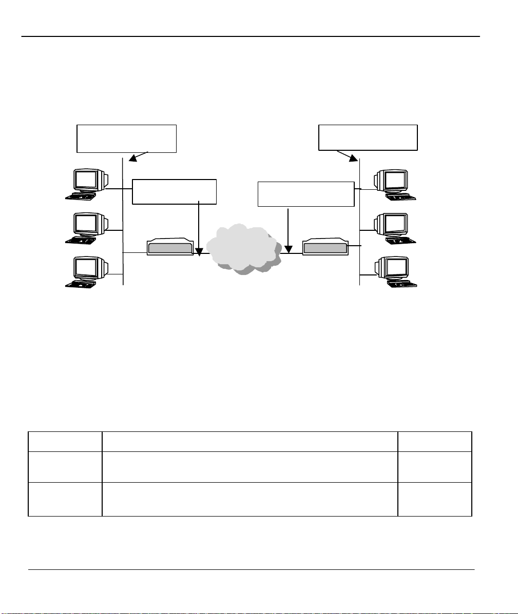
Prestige 480 Dual BRI ISDN Router
192.168.1.0
The following diagram explains the Sample IP Addresses to help you to understand the field of My Wan
Addr in Menu 11.3.
Remote Network
Prestige 480
Local Network
Prestige 480
Figure 5-5 Sample IP Addresses for a TCPI/IP LAN-to-LAN Connection
To configure the TCP/IP parameters of a remote node, first configure the two fields in Menu 11 -1 Remote
Node Profile, as shown in the table below. For more details on the IP Option fields, refer to Chapter 3 –
Internet Access Application.
Table 5-1 TCP/IP related fields in Remote Node Profile
Field Description Option
Rem IP
Address
Edit IP Press the space bar to select Yes and press [Enter] to go to Menu
Enter the IP address of the remote gateway in Remote Node Profile.
11.3 - Remote Node Network Layer Options Menu.
Yes
(Yes/No)
5-4 Remote Node TCP/IP Configuration
 Loading...