

Page 1

2864 Series Modem
User’s Manual
Document No.: 8406, Rev. 1.0
ZyXEL COMMUNICATIONS CORPORATION
i
Page 2

Limited Warranty
ZyXEL Communications Corporation warrants to the original retail purchaser that
this product is free from defects in materials or workmanship for a period of two (2)
years from the date of purchase. If, during the warranty period, and upon proof of
purchase, the product should have indications of failure due to faulty workmanship
and/or materials, ZyXEL will, at its option, repair or replace the defective products
or components without charge for either parts or labor, and to whatever extent it
shall deem necessary to restore the product or component to proper operating condition. Any replacement will be a new or remanufactured functionally equivalent
product of equal value, and will be solely at the option of ZyXEL. This warranty
shall not apply if the product is modified, misused, tampered with, damaged by
natural causes, or subjected to abnormal working conditions.
NOTE: REPAIR OR REPLACEMENT AS PROVIDED UNDER THIS WARRANTY IS
THE EXCLUSIVE REMEDY OF THE PURCHASER. THIS WARRANTY IS IN LIEU OF
ALL OTHER WARRANTIES, EXPRESS OR IMPLIED, INCLUDING ANY IMPLIED
WARRANTY OF MERCHANTABILITY OR FITNESS FOR A PARTICULAR USE OR
PURPOSE. ZYXEL COMMUNICATIONS CORPORATION SHALL IN NO EVENT BE
HELD LIABLE FOR INDIRECT OR CONSEQUENTIAL DAMAGES OF ANY KIND OR
CHARACTER TO THE PURCHASER.
To obtain the services of this warranty, please contact ZyXEL SERVICE CENTER
(refer to the separate WARRANTY CARD) for your Return Material Authorization number (RMA). Products must be returned Postage Prepaid. It is recommended that the unit be insured when shipped. Any returned products without
proof of purchase or those with an expired warranty will be repaired or replaced (at
the option of ZyXEL) and the customer will be billed for parts and labor. All
repaired or replaced products will be shipped by ZyXEL to the corresponding
return address, Postage Paid (USA and territories only). If the customer desires
some other return destination beyond the USA borders, the customer shall bear the
cost of the return shipment. This warranty gives you specific legal rights, and you
may also have other rights which vary from state to state and from country to country.
ii
Page 3

Notice: ZyXEL COMMUNICATIONS CORPORATION does not assume any liability
arising out of the application or use of any products, or software
described herein, neither does it convey any license under its patent
rights nor the patent rights of others. ZyXEL COMMUNICATIONS
CORPORATION further reserves the right to make changes in any
products described herein without notice. This document is subject to
change without notice.
PUBLISHED BY:
ZyXEL COMMUNICATIONS CORPORATION
2F., 58 Park Avenue II
Science-Based Industrial Park
Hsinchu, Taiwan 30077 R.O.C.
EDITED BY:
Computer Software Manuals, Christian Schmitz-Moormann
Wölfelstraße 4, 95444 Bayreuth, Germany
Turtle-Soft EDV-Beratung, D. Katzschke
Hufelandstraße 5, 30453 Hannover, Germany
1995 by ZyXEL Communications Corporation
All rights reserved.
No part of the contents of this publication may be reproduced or transmitted in
any form or by any means without the written permission of the publisher.
iii
Page 4

Acknowledgments
Trademarks mentioned in this manual are used for plain informational purpose.
Trademarks are properties of their respective owners.
U-Modem, ZFAX and ZyXEL are trademarks of ZyXEL Communications
Corporation.
Smartmodem is a registered trademark of Hayes Microcomputer Products, Inc.
MNP is a registered trademark of Microcom, Inc.
IBM PC, XT, AT and OS/2 are trademarks of I nternational Business M achine Cor-
poration.
Touch-tone is a trademark of American Telephone and Telegraph Corporation.
WINDOWS is a trademark of Microsoft Corporation.
ATARI, ST, STE, MEGA STE, TT, and Falcon030 are trademarks or registered
trademarks of Atari Corporation.
Apple, Macintosh, and Lisa are registered trademarks of Apple Computer Inc.
NeXT, NeXT Cube, and NeXT Station are registered trademarks of NeXT, Inc.
Amiga is a registered trademark of Commodore Business Machines.
.
iv
Page 5

FCC Part 15 Information
This device complies with Part 15 of FCC rules. Operation is subject to the following two conditions:
1) This device may not cause harmful interference.
2) This device must accept any interference received, including
interference that may cause undesired operations.
This equipment has been tested and found to comply with the limits for a CLASS
B digital device pursuant to Part 15 of the FCC Rules. These limits are designed to
provide reasonable protection against harmful interference in a residential installation. This equipment generates, uses, and can radiate radio frequency energy, and if
not installed and used in accordance with the instructions, may cause harmful
interference to radio communications. However, there is no guarantee that interference will not occur in a particular installation.
If this equipment does cause harmful interference to radio/television reception,
which can be determined by turning the equipment off and on, the user is encouraged to try to correct the interference by one or more of the following measures:
• Reorient or relocate the receiving antenna.
• Increase the separation between the equipment and the receiver.
• Connect the equipment into an outlet on a circuit different from that to
which the receiver is connected.
• Consult the dealer or an experienced radio/TV technician for help.
Changes or modifications not expressly approved by the party responsible for compliance could void the user's authority to operate the equipment. Shielded RS-232
cables are required to be used to ensure compliance with FCC Part 15, and it is the
responsibility of the user to provide and use shielded RS-232 cables.
FCC REQUIREMENTS
This equipment complies with Part 68 of the FCC Rules. On the base unit of this
equipment is a label that contains, among other information, the FCC Registration
Number and the Ringer Equivalence Number (REN) for this equipment. IF
REQUESTED, THIS INFORMATION MUST BE GIVEN TO THE TELEPHONE COMPANY.
The REN is useful to determine the quantity of the devices you may connect to
your telephone line and still have all of those devices ring when your telephone
number is called. In most, but not all areas, the sum of the REN's of all devices
connected to one line should not exceed five (5.0). To be certain of the number of
devices you may connect to your line, as determined by the total RENs, you should
v
Page 6

contact your local telephone company to determine the maximum REN for your
calling area.
If your equipment causes harm to the telephone network, the telephone company
may discontinue your service temporarily. If possible, they will notify you in
advance. But if advance notice isn't practical, you will be notified as soon as possible. You will be informed of your right to file a complaint with the FCC.
Your telephone company may make changes in its facilities, equipment, operations,
or procedures that could affect the proper functioning of your equipment. If they
do, you will be notified in advance to give you an opportunity to maintain uninterrupted telephone service.
If you experience trouble with this telephone equipment, please contact the Address
and Phone number listed in the warranty card for information on obtaining service
or repairs.
The telephone company may ask that you disconnect this equipment from the network until the problem has been corrected or until you are sure the equipment is
not malfunctioning.
The user is not authorized to repair or modify the equipment beyond replacing the
EPROMs containing the firmware or uploading firmware into the flash EPROM.
This equipment may not be used on coin service provided by the telephone company. Connection to party lines is subject to state tariffs.
TELEPHONE COMPANY REQUIREMENTS
It is not necessary to notify your telephone company before installing the modem,
but your telephone company may request the following information:
• Telephone number to which the modem is connected.
• Manufacturer and Model Number:
ZyXEL Communications Corporation
Model Name FCC Part 68 Approval Number REN#
You will find this information on the sticker label on the bottom case.
The modem is connected to a public switched line using a USOC (Universal Serv-
ice Order Code) RJ11C modular jack, and to a leased line using a JM8 jack.
vi
Page 7

Information for Canadian Users
The Industry Canada (IC, formerly DOC) label identifies certified equipment.
This certification means that the equipment meets certain telecommunications network protective, operational, and safety requirements. IC does not guarantee that
the equipment will operate to a user’s satisfaction.
Before installing this equipment, users should ensure that it is permissible to be
connected to the facilities of the local telecommunications company. The equipment must also be installed using an acceptable method of connection. In some
cases, the company's inside wiring associated with a single line individual service
may be extended by means of a certified connector assembly (telephone extension
card). The customer should be awar e that the compliance with the above conditions
may not prevent degradation of service in some situations.
Repairs to certified equipment should be made by an authorized Canadian maintenance facility designated by the supplier. Any r epairs or alterations made by the user
to this equipment, or equipment malfunctions, may give the telecommunications
company cause to request the user to disconnect the equipment.
For their own protection, users should ensure that the electrical ground connections
of the power utility, telephone lines, and internal metallic water pipe system, if
present, are connected together.Tthis precaution may be particularly important in
rural areas.
Caution: Users should not attempt to make such connections themselves, but
should contact the appropriate electrical inspection authority, or electrician, as
appropriate.
The Load Number (LN) assigned to each terminal device denotes the percentage of
the total load to be connected to the telephone loop used by the device without
overloading. The termination on a loop may consist of any combination of devices,
subject only to the requirement that the total of the Load Numbers of all the
devices not exceed 100.
This digital apparatus does not exceed the class B limits for radio noise emissions
from digital apparatus set out in the radio interference regulations of Industry Canada (formerly Canadian DOC).
vii
Page 8

viii
Page 9

TABLE OF CONTENTS
FCC Part 15 Information . . . . . . . . . . . . . . . . . . . . . . . . . . v
FCC REQUIREMENTS. . . . . . . . . . . . . . . . . . . . . . . . . . . . v
TELEPHONE COMPANY REQUIREMENTS. . . . . . . . . . . . . . . . . . .vi
Information for Canadian Users . . . . . . . . . . . . . . . . . . . . . . vii
BASIC OVERVIEW
INTRODUCTION 1-1
How To Use This Manual. . . . . . . . . . . . . . . . . . . . . . . . .1-2
Compatibility . . . . . . . . . . . . . . . . . . . . . . . . . . . . . .1-3
The 2864 Series Standard Features . . . . . . . . . . . . . . . . . . . .1-4
Additional specific features . . . . . . . . . . . . . . . . . . . . . . . .1-6
ISDN Ready or Upgradeable . . . . . . . . . . . . . . . . . . . . . . .1-6
Voice Playback and Recording . . . . . . . . . . . . . . . . . . . . . .1-6
Telephony Capability. . . . . . . . . . . . . . . . . . . . . . . . . . .1-6
Parallel and Serial Port Interface . . . . . . . . . . . . . . . . . . . . .1-7
DRAM Expandability . . . . . . . . . . . . . . . . . . . . . . . . . . .1-7
Flash EPROM for Easy Firmware Update. . . . . . . . . . . . . . . . . .1-7
Before You Start . . . . . . . . . . . . . . . . . . . . . . . . . . . . .1-7
How To Become A Registered Owner . . . . . . . . . . . . . . . . . . .1-8
What You Need To Have . . . . . . . . . . . . . . . . . . . . . . . . .1-8
Communication Software. . . . . . . . . . . . . . . . . . . . . . . . .1-8
Connecting To Your Phone . . . . . . . . . . . . . . . . . . . . . . . .1-9
Dial-Up Or Leased Line. . . . . . . . . . . . . . . . . . . . . . . . . .1-9
MODEM AND FAX BASICS 2-1
Modem . . . . . . . . . . . . . . . . . . . . . . . . . . . . . . . . .2-1
DTE and DCE . . . . . . . . . . . . . . . . . . . . . . . . . . . . . .2-1
RS-232C or EIA-232D/E . . . . . . . . . . . . . . . . . . . . . . . . .2-1
Serial Port. . . . . . . . . . . . . . . . . . . . . . . . . . . . . . . .2-2
Serial RS-232C Cable . . . . . . . . . . . . . . . . . . . . . . . . . .2-2
Synchronous and Asynchronous Communication. . . . . . . . . . . . . .2-2
UART . . . . . . . . . . . . . . . . . . . . . . . . . . . . . . . . . .2-2
Modem Standards and Speeds . . . . . . . . . . . . . . . . . . . . . .2-3
Type of Telephone Line. . . . . . . . . . . . . . . . . . . . . . . . . .2-3
Intelligent Modem . . . . . . . . . . . . . . . . . . . . . . . . . . . .2-4
ISDN . . . . . . . . . . . . . . . . . . . . . . . . . . . . . . . . . .2-4
AT Command Set . . . . . . . . . . . . . . . . . . . . . . . . . . . .2-5
V.25bis Command Set . . . . . . . . . . . . . . . . . . . . . . . . . .2-5
Error Correction . . . . . . . . . . . . . . . . . . . . . . . . . . . . .2-5
Data Compression . . . . . . . . . . . . . . . . . . . . . . . . . . . .2-6
TOC-1
Page 10

MNP Protocols . . . . . . . . . . . . . . . . . . . . . . . . . . . . 2-6
V.42bis and V.42 . . . . . . . . . . . . . . . . . . . . . . . . . . . 2-6
Xmodem, Ymodem, and Zmodem. . . . . . . . . . . . . . . . . . . . 2-7
Fax and Facsimile . . . . . . . . . . . . . . . . . . . . . . . . . . . 2-7
Fax Card . . . . . . . . . . . . . . . . . . . . . . . . . . . . . . . 2-7
Modem as a Fax . . . . . . . . . . . . . . . . . . . . . . . . . . . . 2-7
EIA Class 1 and Class 2/2.0 Fax Commands . . . . . . . . . . . . . . . 2-8
Autodetection of Fax or Data Call . . . . . . . . . . . . . . . . . . . . 2-8
Caller ID. . . . . . . . . . . . . . . . . . . . . . . . . . . . . . . . 2-8
Distinctive Ring. . . . . . . . . . . . . . . . . . . . . . . . . . . . . 2-8
Digitized Voice . . . . . . . . . . . . . . . . . . . . . . . . . . . . . 2-9
Cellular Modem . . . . . . . . . . . . . . . . . . . . . . . . . . . . 2-9
Automatic Redial / Call Hunting . . . . . . . . . . . . . . . . . . . . . 2-9
Modem Approval and Legal Matters . . . . . . . . . . . . . . . . . . .2-10
MODEM INSTALLATION 3-1
External Modems. . . . . . . . . . . . . . . . . . . . . . . . . . . . 3-1
Elite 2864 . . . . . . . . . . . . . . . . . . . . . . . . . . . . . . . 3-1
Elite 2864 Front Panel . . . . . . . . . . . . . . . . . . . . . . . . . 3-1
Elite 2864 Rear Panel . . . . . . . . . . . . . . . . . . . . . . . . . 3-4
Connecting the Elite 2864 . . . . . . . . . . . . . . . . . . . . . . . 3-5
Turning on the Elite 2864. . . . . . . . . . . . . . . . . . . . . . . . 3-6
Elite 2864L . . . . . . . . . . . . . . . . . . . . . . . . . . . . . . 3-6
Elite 2864L Front Panel. . . . . . . . . . . . . . . . . . . . . . . . . 3-7
Elite 2864L Rear Panel . . . . . . . . . . . . . . . . . . . . . . . . . 3-7
Connecting the Elite 2864L . . . . . . . . . . . . . . . . . . . . . . . 3-7
Turning on the Elite 2864L . . . . . . . . . . . . . . . . . . . . . . . 3-7
Elite 2864I and Elite 2864IU . . . . . . . . . . . . . . . . . . . . . . 3-7
Supreme 2864L . . . . . . . . . . . . . . . . . . . . . . . . . . . . 3-7
Supreme 2864L Front Panel . . . . . . . . . . . . . . . . . . . . . . 3-8
Supreme 2864L Rear Panel. . . . . . . . . . . . . . . . . . . . . . . 3-8
Connecting the Supreme 2864L. . . . . . . . . . . . . . . . . . . . . 3-9
Turning on the Supreme 2864L . . . . . . . . . . . . . . . . . . . . . 3-9
Supreme 2864I and 2864IU . . . . . . . . . . . . . . . . . . . . . . 3-9
Omni 288P and Omni 288S . . . . . . . . . . . . . . . . . . . . . .3-10
Omni 288P Front Panel. . . . . . . . . . . . . . . . . . . . . . . . .3-10
Omni 288S Front Panel. . . . . . . . . . . . . . . . . . . . . . . . .3-10
Omni 288P Rear Panel. . . . . . . . . . . . . . . . . . . . . . . . .3-11
Omni 288S Rear Panel . . . . . . . . . . . . . . . . . . . . . . . . .3-12
Connecting the Omni 288P . . . . . . . . . . . . . . . . . . . . . . .3-12
Connecting the Omni 288S . . . . . . . . . . . . . . . . . . . . . . .3-13
Turning on the Omni 288P or Omni 288S . . . . . . . . . . . . . . . .3-13
TOC-2
Page 11

MODEM OPERATION
MODEM OPERATION 4-1
Parallel or Serial Port Operation. . . . . . . . . . . . . . . . . . . . . .4-1
PC Parallel Port Operation . . . . . . . . . . . . . . . . . . . . . . . .4-2
Parallel Port under Windows . . . . . . . . . . . . . . . . . . . . . . .4-2
Parallel Port under DOS . . . . . . . . . . . . . . . . . . . . . . . . .4-2
Parallel Port Speed Limit . . . . . . . . . . . . . . . . . . . . . . . . .4-2
ZyXEL Parallel Port Adapter. . . . . . . . . . . . . . . . . . . . . . . .4-3
Using the Microphone and Speaker Jacks . . . . . . . . . . . . . . . . .4-3
Non-volatile Memory. . . . . . . . . . . . . . . . . . . . . . . . . . .4-3
Firmware Update/Upgrade . . . . . . . . . . . . . . . . . . . . . . . .4-3
DRAM Upgrade . . . . . . . . . . . . . . . . . . . . . . . . . . . . .4-5
Resetting The Modem . . . . . . . . . . . . . . . . . . . . . . . . . .4-5
2864 QUICK START 5-1
LCD Panel . . . . . . . . . . . . . . . . . . . . . . . . . . . . . . .5-1
Panel Operation . . . . . . . . . . . . . . . . . . . . . . . . . . . . .5-2
Menu Tree. . . . . . . . . . . . . . . . . . . . . . . . . . . . . . . .5-2
LED Status Screen . . . . . . . . . . . . . . . . . . . . . . . . . . . .5-2
Double Arrows on The Screen. . . . . . . . . . . . . . . . . . . . . . .5-3
Dialing . . . . . . . . . . . . . . . . . . . . . . . . . . . . . . . . .5-3
Dial Memory . . . . . . . . . . . . . . . . . . . . . . . . . . . . . .5-4
Storing a Number . . . . . . . . . . . . . . . . . . . . . . . . . . . .5-4
Dial Number . . . . . . . . . . . . . . . . . . . . . . . . . . . . . .5-5
Manual Dial and the DATA/VOICE Switches . . . . . . . . . . . . . . . .5-5
Repeat Last Dial . . . . . . . . . . . . . . . . . . . . . . . . . . . . .5-6
Auto Answer. . . . . . . . . . . . . . . . . . . . . . . . . . . . . . .5-6
Dialing Messages . . . . . . . . . . . . . . . . . . . . . . . . . . . .5-7
Panel Lock . . . . . . . . . . . . . . . . . . . . . . . . . . . . . . .5-9
MODEM PARAMETER SETTINGS 6-1
Parameter Menu. . . . . . . . . . . . . . . . . . . . . . . . . . . . .6-1
Parameter Selection . . . . . . . . . . . . . . . . . . . . . . . . . . .6-2
Status Register Content Modification. . . . . . . . . . . . . . . . . . . .6-2
Menu Tree Elements . . . . . . . . . . . . . . . . . . . . . . . . . . .6-2
TERMINAL OPTIONS . . . . . . . . . . . . . . . . . . . . . . . . . . .6-3
MODEM OPTIONS . . . . . . . . . . . . . . . . . . . . . . . . . . . .6-6
ERROR CONTROL . . . . . . . . . . . . . . . . . . . . . . . . . . . 6-11
AUDIO OPTIONS . . . . . . . . . . . . . . . . . . . . . . . . . . . . 6-12
TOC-3
Page 12

SETTINGS AND COMMANDS
PROFILES 7-1
Resetting from Profile . . . . . . . . . . . . . . . . . . . . . . . . . . 7-6
Saving to Profile . . . . . . . . . . . . . . . . . . . . . . . . . . . . 7-7
Profile Protection . . . . . . . . . . . . . . . . . . . . . . . . . . . . 7-7
Resetting Profiles . . . . . . . . . . . . . . . . . . . . . . . . . . . . 7-8
STATUS REGISTERS 8-1
Reading and Setting S-Registers . . . . . . . . . . . . . . . . . . . . . 8-1
S-Register Descriptions . . . . . . . . . . . . . . . . . . . . . . . . . 8-3
ZyXEL-specific Registers. . . . . . . . . . . . . . . . . . . . . . . . . 8-5
AT COMMAND SET SUMMARY 9-1
Basic AT Command Set. . . . . . . . . . . . . . . . . . . . . . . . . 9-1
Extended AT& Command Set . . . . . . . . . . . . . . . . . . . . . . 9-6
Extended AT* Command Set . . . . . . . . . . . . . . . . . . . . . .9-10
SPECIAL FUNCTIONS
ERROR CONTROL AND DATA COMPRESSION 10-1
Error Control . . . . . . . . . . . . . . . . . . . . . . . . . . . . . .10-1
Data Compression . . . . . . . . . . . . . . . . . . . . . . . . . . .10-2
Run-length Encoding . . . . . . . . . . . . . . . . . . . . . . . . . .10-3
Adaptive Frequency Encoding . . . . . . . . . . . . . . . . . . . . . .10-3
String Coding . . . . . . . . . . . . . . . . . . . . . . . . . . . . .10-3
Bidirectional Compression. . . . . . . . . . . . . . . . . . . . . . . .10-4
Negotiation Fail Fall-Back. . . . . . . . . . . . . . . . . . . . . . . .10-4
DTE to DCE Connection. . . . . . . . . . . . . . . . . . . . . . . . .10-4
Averaging Throughput . . . . . . . . . . . . . . . . . . . . . . . . .10-4
Hints for High-speed Operation . . . . . . . . . . . . . . . . . . . . .10-5
Flow Control . . . . . . . . . . . . . . . . . . . . . . . . . . . . . .10-5
Hardware CTS/RTS Flow Control. . . . . . . . . . . . . . . . . . . . .10-5
Software XON/XOFF Flow Control . . . . . . . . . . . . . . . . . . . .10-5
SYNCHRONOUS OPERATION 11-1
Clock Options . . . . . . . . . . . . . . . . . . . . . . . . . . . . .11-1
RTS Options . . . . . . . . . . . . . . . . . . . . . . . . . . . . . .11-1
Half-Duplex Operation . . . . . . . . . . . . . . . . . . . . . . . . .11-2
Mode Options . . . . . . . . . . . . . . . . . . . . . . . . . . . . .11-2
Dial from Synchronous Mode . . . . . . . . . . . . . . . . . . . . . .11-2
Auto-answer from Synchronous Mode . . . . . . . . . . . . . . . . . .11-3
Manual Answer from Synchronous Mode. . . . . . . . . . . . . . . . .11-3
Change from Synchronous Mode into Asynchronous Mode . . . . . . . .11-3
Setting up a ZyXEL Modem with the AS-400 . . . . . . . . . . . . . . .11-3
TOC-4
Page 13

LEASED-LINE OPERATION 12-1
Connecting to a Leased Line . . . . . . . . . . . . . . . . . . . . . . 12-1
Line Type . . . . . . . . . . . . . . . . . . . . . . . . . . . . . . . 12-1
Power Level. . . . . . . . . . . . . . . . . . . . . . . . . . . . . . 12-2
Handshake Mode . . . . . . . . . . . . . . . . . . . . . . . . . . . 12-2
Manual Connection . . . . . . . . . . . . . . . . . . . . . . . . . . 12-2
Auto-handshake . . . . . . . . . . . . . . . . . . . . . . . . . . . . 12-2
Leased-Line Dial Backup. . . . . . . . . . . . . . . . . . . . . . . . 12-3
Dial Backup. . . . . . . . . . . . . . . . . . . . . . . . . . . . . . 12-3
Aborting from Leased-Line Operation . . . . . . . . . . . . . . . . . . 12-4
Disconnecting a Leased-Line Connection . . . . . . . . . . . . . . . . 12-4
SPECIAL FUNCTIONS 13-1
Security Function . . . . . . . . . . . . . . . . . . . . . . . . . . . 13-1
Remote Configuration . . . . . . . . . . . . . . . . . . . . . . . . . 13-2
Caller Number Delivery(CND). . . . . . . . . . . . . . . . . . . . . . 13-4
Distinctive Ring . . . . . . . . . . . . . . . . . . . . . . . . . . . . 13-5
Extended Distinctive Ring. . . . . . . . . . . . . . . . . . . . . . . . 13-6
Setting Up The EDR . . . . . . . . . . . . . . . . . . . . . . . . . . 13-7
Application Example . . . . . . . . . . . . . . . . . . . . . . . . . . 13-9
V.25bis Command Set . . . . . . . . . . . . . . . . . . . . . . . . . 13-9
CELLULAR MODE OPERATION 14-1
Cellular Phone Systems . . . . . . . . . . . . . . . . . . . . . . . . 14-1
Cellular Impairments. . . . . . . . . . . . . . . . . . . . . . . . . . 14-1
Cellular Modems and ZyCellular Technology. . . . . . . . . . . . . . . 14-2
ZyXEL ZyCellular Modes . . . . . . . . . . . . . . . . . . . . . . . . 14-3
Cellular Mode Usage. . . . . . . . . . . . . . . . . . . . . . . . . . 14-3
Cellular Modem Installation. . . . . . . . . . . . . . . . . . . . . . . 14-4
FAX OPERATION 15-1
ITU-T T.30 Fax Protocol . . . . . . . . . . . . . . . . . . . . . . . . 15-1
Fax Command Sets . . . . . . . . . . . . . . . . . . . . . . . . . . 15-2
Class 1 Command Set . . . . . . . . . . . . . . . . . . . . . . . . . 15-2
Class 2 Command Set . . . . . . . . . . . . . . . . . . . . . . . . . 15-3
Extended Fax AT Commands . . . . . . . . . . . . . . . . . . . . . 15-13
Flow Control. . . . . . . . . . . . . . . . . . . . . . . . . . . . . 15-16
Parallel Receiving with the Fax Machine. . . . . . . . . . . . . . . . 15-17
Fax reception from within a BBS System. . . . . . . . . . . . . . . . 15-17
Direct FAX Reception and Printing. . . . . . . . . . . . . . . . . . . 15-18
Stand-alone FAX Reception and Storing . . . . . . . . . . . . . . . . 15-20
TOC-5
Page 14

ADVANCED VOICE CAPABILITY 16-1
Voice Data Compression . . . . . . . . . . . . . . . . . . . . . . . .16-1
Automatic Detection of Voice, Fax and Data . . . . . . . . . . . . . . .16-2
Voice States and Operation Modes. . . . . . . . . . . . . . . . . . . .16-2
Voice Command State . . . . . . . . . . . . . . . . . . . . . . . . .16-3
Voice Data State . . . . . . . . . . . . . . . . . . . . . . . . . . . .16-4
Voice Data Transmission State. . . . . . . . . . . . . . . . . . . . . .16-4
Voice Data Receival State . . . . . . . . . . . . . . . . . . . . . . . .16-4
Events and Actions with Shielded Code. . . . . . . . . . . . . . . . . .16-5
Event Detection and Reporting. . . . . . . . . . . . . . . . . . . . . .16-5
Action Commands in Voice Data State . . . . . . . . . . . . . . . . . .16-7
Voice AT Commands . . . . . . . . . . . . . . . . . . . . . . . . . .16-8
Supported Commands For Voice Mode Operation . . . . . . . . . . . . .16-9
Action Voice Commands for Voice Mode Operation . . . . . . . . . . . 16-12
Configuration Commands for Voice Mode Operation. . . . . . . . . . . 16-14
Examples of Voice Mode Operation . . . . . . . . . . . . . . . . . . 16-20
Connecting a Telephone Set to the Modem's PHONE Jack . . . . . . . . . 16-27
NETWORK MANAGEMENT CAPABILITY 17-1
ZyXEL Modem Network Management System . . . . . . . . . . . . . . .17-1
Hierarchical Modem Network . . . . . . . . . . . . . . . . . . . . . .17-1
Distributed Management . . . . . . . . . . . . . . . . . . . . . . . .17-1
NMS Capable Models. . . . . . . . . . . . . . . . . . . . . . . . . .17-2
DIAGNOSTICS 18-1
Power-on Self-test . . . . . . . . . . . . . . . . . . . . . . . . . . .18-1
Analog Loopback Test (AT&T1) . . . . . . . . . . . . . . . . . . . . .18-2
Analog Loopback with Self-test (AT&T8) . . . . . . . . . . . . . . . . .18-3
Local Digital Loopback Test (AT&T3) . . . . . . . . . . . . . . . . . .18-3
Remote Digital Loopback Test (AT&T6) . . . . . . . . . . . . . . . . .18-4
Remote Digital Loopback with Self-test (AT&T7) . . . . . . . . . . . . .18-4
Line Condition Status Display . . . . . . . . . . . . . . . . . . . . . .18-5
Link Status Report (ATI2) . . . . . . . . . . . . . . . . . . . . . . . .18-7
Throughput Display. . . . . . . . . . . . . . . . . . . . . . . . . . 18-10
Retransmission Indicator . . . . . . . . . . . . . . . . . . . . . . . 18-10
Dialing Indicator . . . . . . . . . . . . . . . . . . . . . . . . . . . 18-10
Handshaking And Retrain Indicator . . . . . . . . . . . . . . . . . . 18-10
Firmware Update . . . . . . . . . . . . . . . . . . . . . . . . . . . 18-10
TOC-6
Page 15

HINTS AND TIPS
GENERAL HINTS AND TIPS 19-1
Activating Saved Settings upon Turning-on. . . . . . . . . . . . . . . . 19-1
Avoiding Low Throughput and Loss of Data . . . . . . . . . . . . . . . 19-1
Disabling Compression May Yield Faster Transfers . . . . . . . . . . . . 19-1
Avoiding Disconnections during a Handshake on a Leased Line . . . . . . . 19-1
Avoiding Disconnections when Making a Data Call. . . . . . . . . . . . 19-1
Calling from an Extension / Blind Dial. . . . . . . . . . . . . . . . . . 19-2
THE FIRST CONNECTION 20-1
ZyXEL MODEMS AND A PC 21-1
Serial Cable . . . . . . . . . . . . . . . . . . . . . . . . . . . . . . 21-1
Parallel Cable . . . . . . . . . . . . . . . . . . . . . . . . . . . . . 21-2
Using the Windows 3.1 Terminal Program. . . . . . . . . . . . . . . . 21-2
Hardware Hints . . . . . . . . . . . . . . . . . . . . . . . . . . . . 21-2
ZyXEL Serial/Parallel I/O Adapter Card. . . . . . . . . . . . . . . . . . 21-3
ZyXEL MODEMS AND UNIX 22-1
Hints for Unix Setups. . . . . . . . . . . . . . . . . . . . . . . . . . 22-1
Cable. . . . . . . . . . . . . . . . . . . . . . . . . . . . . . . . . 22-1
Installation . . . . . . . . . . . . . . . . . . . . . . . . . . . . . . 22-1
Software Tips . . . . . . . . . . . . . . . . . . . . . . . . . . . . . 22-2
ZyXEL MODEMS AND APPLE MACINTOSH 23-1
Connector. . . . . . . . . . . . . . . . . . . . . . . . . . . . . . . 23-1
Apple Macintosh Particularities . . . . . . . . . . . . . . . . . . . . . 23-1
Cable. . . . . . . . . . . . . . . . . . . . . . . . . . . . . . . . . 23-2
Software for the Apple Macintosh . . . . . . . . . . . . . . . . . . . . 23-3
ZyXEL MODEMS AND ATARIS 24-1
Cable. . . . . . . . . . . . . . . . . . . . . . . . . . . . . . . . . 24-1
Hardware Tips. . . . . . . . . . . . . . . . . . . . . . . . . . . . . 24-2
Software Tips . . . . . . . . . . . . . . . . . . . . . . . . . . . . . 24-2
ZyXEL MODEMS AND AMIGA 25-1
Cable. . . . . . . . . . . . . . . . . . . . . . . . . . . . . . . . . 25-1
Software Tips . . . . . . . . . . . . . . . . . . . . . . . . . . . . . 25-2
Hardware Tips. . . . . . . . . . . . . . . . . . . . . . . . . . . . . 25-2
TOC-7
Page 16

APPENDICES
GLOSSARY GLO-1
EIA-232D INTERFACE A-1
PHONE JACK PIN ASSIGNMENTS B-1
ZyXEL PARALLEL PORT INTERFACE C-1
V.25bis COMMAND SET D-1
STANDARDS E-1
ASCII Control Characters . . . . . . . . . . . . . . . . . . . . . . . . E-1
Selection of ITU-T standards. . . . . . . . . . . . . . . . . . . . . . . E-2
Data transmission through telephone networks (V.1 -V.110). . . . . . . . E-3
INDEX Index-1
TOC-8
Page 17

Chapter 1
INTRODUCTION
The 2864 series of V.34 modems includes three sub-series of models, namely the Supreme, Elite and Omni series. The Supreme and Elite series models have ISDN capability or can be upgraded to have ISDN capability . The Omni series does not have
ISDN capability . The Supreme series provides an LCD display panel while the Elite
series has a front panel with LED indicators only. Many features are common to all
three series. If not noted otherwise, a feature illustrated with one series model in this
manual applies to the other models and series as well.
The Elite 2864 series of high-speed modems features four base 10models. They differ only in the implemented line interface module, everything else is equivalent except for the panel LED indicator designations.
The models are
Model Name
Elite 2864 Dial-up line DAA Dial-up analog PSTN line
Elite 2864L Dial-up and leased line
Elite 2864I ISDN S-interface ISDN line, S-interface
Elite 2864IU ISDN U-interface ISDN line, U-interface
The Elite 2864 has a 2-wire dial-up line DAA (Direct Access Arrangement) module
for connection to a normal PSTN (Public Switched Telephone Network) 2-wire
dial-up phone line. The Elite 2864L has a DAA with both a dial-up and leased line
interface. A 2 or a 4-wire leased line can also be used besides the normal 2-wire dialup line. Dial back-up capability is provided while using leased line. The Elite 2864I
has an ISDN S-interface module that will connect to an ISDN S-interface line. It
will connect to an ISDN call or a modem/fax call from PSTN made to this ISDN
line. A U-interface ISDN module is available for the USA market. The Elite 2864IU
is the ISDN model with the U-interface module.
By changing the line interface module, one Elite model will essentially become another Elite model. Each Elite model has different markings on its front and rear panels. Thus, in addition to the line interface module the front and rear panel also need
to be changed in order to transform one Elite model into a different Elite model.
Note that each Elite model has its own telecommunication authority approval
Line Interface Module Phone Line Used
Dial-up and/or 2/4-wire leased ana-
DAA
log line
1–1
Page 18

number. When the model is changed, the approval number is also changed. F ind the
new approval number and check whether it is appropriate for the user to do the
model transformation before you start the transformation process.
Like the Elite series, the Supreme series includes different models which differ only
in the line interface module. There are three models in the Supreme series - The Supreme 2864L, 2864I, and 2864IU. The S upreme 2864L has a DAA with both a dialup and leased-line interface; the Supreme 2864I has an ISDN S-interface module;
the Supreme 2864IU has an ISDN U-interface module.
The Omni series models have only modem/fax/voice capability . They do not pro vide
ISDN capability nor are they ISDN upgradeable. The Omni 288P is the model with
a parallel port DTE interface and the Omni 288S is with a serial port DTE interface.
The Supreme and Elite models have both a parallel port and a serial port DTE interface.
How To Use This Manual
This manual describes the use of all models in the 2864 series and gives instruction
for their installation and operation. The 2864I and 2864IU ISDN models come
with a separate manual describing their ISDN operation.
The manual is divided into five sections.
Basic Overview - The first section is comprised of chapter 1 (INTRODUCTION)
through chapter 3 (MODEM INSTALLATION). It gives a basic overview of the
2864 series modems' features, introduces some basics of modem operation for novice users, and explains the installation of the different models of the 2864 series.
Modem Operation - The second section introduces you to some skills you will need
to make the best use of your modem. In chapter 4 (MODEM OPERATION) you are
introduced to the use of the different modem ports and you will find information
on how to return the modem to standard settings (reset) and how to upgrade your
modem in the future. The panel operation of the Supreme models is described in
chapter 5 (2864 QUICK START) and chapter 6 (MODEM PARAMETER SETTINGS). Users of the non-LCD models should consult the equivalent A T command
sections listed for each of the panel operations.
Settings and Commands - The third section, chapter 7 (PROFILES) through
chapter 9 (AT COMMAND SET SUMMARY), provides an overview of the settings
and commands which are available in the 2864 series.
Special Functions - Section four is comprised of chapter 10 (ERROR CONTROL
AND DATA COMPRESSION) through chapter 18 (DIAGNOSTICS) and describes
many special functions of the 2864 series modems in detail, including data compression, synchronous and leased-line operation, remote configuration, caller ID, cellu-
1–2
Page 19

lar mode, fax sending and receiving, voice mail, network management, and
diagnostic features.
Hints and T ips - Section five is the trouble-shooting and special advice section. Here
you will find additional information on how to use a 2864 series modem with your
computer, and some hints and tips r elating to a number of communication software
applications.
Appendices - An extensive glossary, several appendices with technical details, information on standards, and a thorough index complete this manual.
Those who need more detailed technical information may contact ZyXEL Communications Corporation directly . The address can be found in the disclaimer section at
the beginning of this manual.
Compatibility
ZyXEL 2864 series modems are high performance universal modems capable of
transmission speeds up to 28.8 Kbps full-duplex on a 2-wire dial-up line. Universal
compatibility covers a broad range of ITU-T and BELL standards, and provides data
compression.
Various operation modes that can be achieved are as follows:
Standard
Bit rate
(+/-0,01%)
[bps]
Baud rate
(+/-0,01%)
[baud]
Modulation Carrier
frequency
[Hz]
V .34 28 800 - 2 400 multiple multiple multiple
ZyXEL 19 200 2 743
ZyXEL 16 800 2 400
V.33
V.33
*
*
14 400 2 400 128-TCM 1800
12 000 2 400 64-TCM 1800
V.32bis 14 400 2 400 128-TCM 1800
V.32bis 12 000 2 400 64-TCM 1800
V.32bis 7 200 2 400 16-TCM 1800
V.32 9 600 2 400 32-TCM 1800
V.32 uncoded 9 600 2 400 16-QAM 1800
V.32 4 800 2 400 4-DPSK 1800
*
V.29
*
V.29
*
V.29
V.27bis
*
9 600 2 400 16-QAM 1700
7 200 2 400 8-QAM 1700
4 800 2 400 4-DPSK 1700
4 800 1 600 8-PSK 1800
1–3
Page 20

Standard
V .27bis
V.26bis
*
*
Bit rate
(+/-0,01%)
[bps]
Baud rate
(+/-0,01%)
[baud]
Modulation Carrier
frequency
[Hz]
2 400 1 200 4-DPSK 1800
2 400 1 200 4-DPSK 1800
V.23 1200 / 75 1200 / 75 FSK
V.23 600 / 75 600 / 75 FSK
†
V.22bis
2 400 600 16-QAM 1200 Orig.
2400 Ans.
†
V.22
(BELL 212A)
1 200 600 4-DPSK 1200 Orig.
2400 Ans.
V.21 300 300 FSK
BELL 103 300 300 FSK
G3 FAX implemented according to T.30, V.17,V.29 and V.27ter.
Cellular Modes ZyXEL proprietary cellular modes; 14400 bps to 4800 bps.
*. V33, V.29, V.27bis and V.26bis are only available in model 2864L for 4-wire
leased-line operation. The other operation modes are common to all models.
V.26bis works in half-duplex mode on 2-wire dial-up line.
†. 1800 Hz guard tone for V.22bis/V .22 answer mode, 6 dB below data signal level.
The 2864 Series Standard Features
• Synchronous/Asynchronous operations for external stand alone models and
rack mount models. (Parallel port interface is for asynchronous transmission
only)
• Asynchronous operations for PC internal card model.
• MNP class 4/5 error correction/data compression.
• V.42/V.42bis error correction/data compression. V.42 with selective reject.
• Extended AT command set.
• V.25bis async/sync command set.
• Operation on 2-wire dial-up line or 2/4-wire leased line. (4-wire leased line on
2864L only.)
• Auto-dial/answer and manual originate/answer.
• Tone/Pulse dialing.
• Dial tone, busy signal, and ringback detection.
• Programmable speaker volume control.
1–4
Page 21

• Non-volatile memory for parameter/setting storage.
• Remote configuration.
• Security call back.
• Caller ID detection.
• Distinctive ring detection.
• Extensive status reports.
• Diagnostics available for:
• Modem full self-test
• Analog loopback (with self-test)
• Remote digital loopback (with self-test)
• Digital loopback
• XON/XOFF software and CTS/RTS hardware flow control.
• Line status monitoring available for (only Supreme 2864):
• Signal-to-noise ratio
• Received signal level
• Frequency offset
• Phase jitter
• Retrain granted
• Retrain requested
• Round trip echo delay
• Carrier loss counter
• Rate change granted.
• Rate change requested
• Blocks retransmitted
• Blocks received in error
• 20×2 LCD and directional keypads. (Supreme 2864 only)
• G3 Fax sending and receiving capability with speeds up to 14400 bps.
• Fax-Polling / Fax-Grouping.
• Automatic detection of data or fax call.
• Digitized voice capability with speech compression.
• DTMF tone detection.
• Special cellular modes for data communication through cellular link.
1–5
Page 22

Additional specific features
ISDN Ready or Upgradeable
The 2864I model has an ISDN module to connect to an ISDN line. On the other
2864 models the phone line interface module may be removed and replaced instead
by an ISDN module to become an ISDN modem. The ISDN modem has both
ISDN capability and normal modem/fax/voice capability.
For ISDN capability, the 2864I supports a 2B+D ISDN basic rate interface. On the
B channel, the 2864I supports one B channel at 64Kbps or two B channels bundled
at 128Kbps. With data compression, the throughput is up to a few hundred Kbps.
The 2864I also supports one B channel for data and the other B channel for voice
communication. On the D channel, the 2864I supports 1TR6 protocol for German
ISDN, DSS1 protocol for Euro ISDN and NI1, AT&T 5ESS and Northern Telecom DMS-100 for North America ISDN.
A full feature analog port (a/b adapter) is provided. Thus, a r egular telephone equipment may be connected to the ISDN line to make and receive ISDN calls through
this port. The metering pulse is also supported on this analog port for countries supporting it.
For modem/fax/voice capability, the 2864I can initiate and receive modem/fax calls
to/from a modem or fax machine connected to a PSTN analog telephone line. V oice
mail capability is also supported for voice calls to/from an ISDN or analog PSTN
line.
Voice Playback and Recording
A normal telephone set may be connected to the phone jack of the modem for local
voice message playback or recording. The modem provides the necessary DC voltage
and current for the telephone set to operate.
A microphone and a speaker jack are also provided for voice recording or playback.
An external microphone, speakers or a headset may be connected to the modem
through these jacks.
A large and good quality internal speaker is installed to provide better sound for
voice and music playback.
Telephony Capability
The 2864 series modem can detect the on/off-hook status or polarity change of the
phone line connection and the attached telephone set. These will be reported as
events in voice mode to the connected computer. The modem can also control and
switch between telephone connecting to line and modem connecting to line. It can
1–6
Page 23

also control the switching between the phone line connecting to the modem and the
telephone set connecting to the modem. Both the modem and the telephone set may
also be connected to the line at the same time. A telephony software program can
utilize these capabilities to support various telephony functions.
Parallel and Serial Port Interface
The Supreme and Elite models have both a serial port and a parallel port. The Omni
model has either a serial or a parallel port. The serial port has a speed up to
460.8Kbps with auto speed detection (AT autobaud). The parallel port can connect
to either a PC's parallel port or a printer's parallel port. When it is connected to a
bidirectional PC parallel port, the PC can communicate with the modem through
the parallel port. The parallel port connection has the advantage that no data loss due
to overrun will occur and there is no serial port speed limit. When the modem's parallel port is connected to a laser printer with a Centronics type interface (the normal
PC to printer parallel interface), the modem can send received fax pages directly to
the printer without the need to start up a PC.
DRAM Expandability
8 Mbyte DRAM expandability is standard on the Supreme and Elite series modems.
Four DRAM sockets are provided on board to accept four 4M×4 16M DRAM
chips. The DRAM memory is useful for overnight stand-alone fax receiving. A bout
200 pages of normal fax can be stored without overflowing the DRAM memory . The
stored fax pages are available for later retrieval or printing.
Flash EPROM for Easy Firmware Update
With the versatile and feature rich hardware architecture, the 2864 series modems
are ready for firmware updates/upgrades for added and enhanced features. An 8
Mbit high-speed flash EPROM is standard on every 2864 modem (4 Mbit on Omni
models). A firmware update is only an A T command to upload a new firmware file.
It is not necessary to open the case or burn any EPROM.
Before You Start
Before you proceed further, please check the modem package and make sur e nothing
is missing. The complete package should include:
1–7
Page 24

• one (1) 2864 series universal modem
• one (1) power adapter (external model)
• one (1) RJ11 telephone cable
• one (1) JM8 leased-line cable (2864L model only)
one (1) RJ45 ISDN telephone cable (2864I model only)
• one (1) 2864 series user’s manual
• one (1) ZFAX 3.5" floppy disk and floppy disk(s) for drivers and other utilities.
• one (1) warranty/registration card
• one (1) Quick Reference Card
Contact your dealer or the store where you bought the modem if anything is missing. Check the modem for shipping damages. If you find any damage, contact the
shipping agency immediately.
Retain the shipping and cushioning materials for future storage or shipping needs.
Please direct any additional questions about damaged or missing materials to your
dealer or distributor, or to the factory address listed on your warranty card.
How To Become A Registered Owner
Fill in the registration card and mail it to the address found on the r everse side of the
card. Registered owners will receive future product and update information. You
don't have to register to receive warranty service. A dated invoice as proof of purchase along with the warranty card are sufficient.
What You Need To Have
You must provide the following additional equipment to operate your modem:
• A Computer/Terminal with communication software.
• A RS-232 serial cable or a 25-wire DB25 parallel cable (with one male and one
female connector).
• A telephone line from your telephone company (dial-up or leased line).
Communication Software
Communication software controls the modem connected to the computer and directs data to and from the modem. In most PC environments, the modem is used in
an asynchronous mode and the software controls the modem by AT commands.
1–8
Page 25

ZyXEL modems support the extended AT command set and are compatible with
most communication software packages. However , there are some unique features in
the ZyXEL modem and there are a few unique commands to control them.
Some communication packages need a file with information about the commands
and features the modem supports. Basic information on how to set up communication software can be found in chapter 20 (THE FIRST CONNECTION). Information and sample data files for popular communication software packages are
available in the Application Driver Area of the ZyXEL BBS (+886-35-787045).
Connecting To Your Phone
If you would like to use a single phone line for voice and modem connections, remove your phone cable from the RJ11 junction box and plug one end of the RJ11
cable (supplied with the modem) into the phone junction box on the wall, then plug
the other end of the cable into the rear panel of the modem labeled DIAL-UP LINE
or WALL. Finish by plugging your phone cable into the r ear panel of the modem labeled PHONE. Please refer to the illustrations in chapter 3 (MODEM INSTALLA-
TION).
Dial-Up Or Leased Line
The 2864 and Omni 288 models may connect to 2-wire dial-up or leased lines only .
The 2864L offers you a choice of connecting to 2-wire dial-up lines (more commonly known as public lines) and 2/4-wire leased lines. To use the 2864L on a leased line,
you must order and install a USOC JM8 jack. You must also specify 4-wire operation without TEK leads for the wiring option. When setting up a pair of modems
for leased line point-to-point operation, one modem must be configured for originate mode and the other for answer mode. Both RJ11C and JM8 cables are supplied
for your convenience.
1–9
Page 26

1–10
Page 27
Chapter 2
MODEM AND FAX BASICS
This chapter is intended for those readers who want to know the details behind modem and fax operations; what's going on behind the scenes. In addition to introducing basic modem and fax terminology , this chapter helps users to understand and be
able to utilize the available features. Experienced modem and fax users may wish to
skip this chapter.
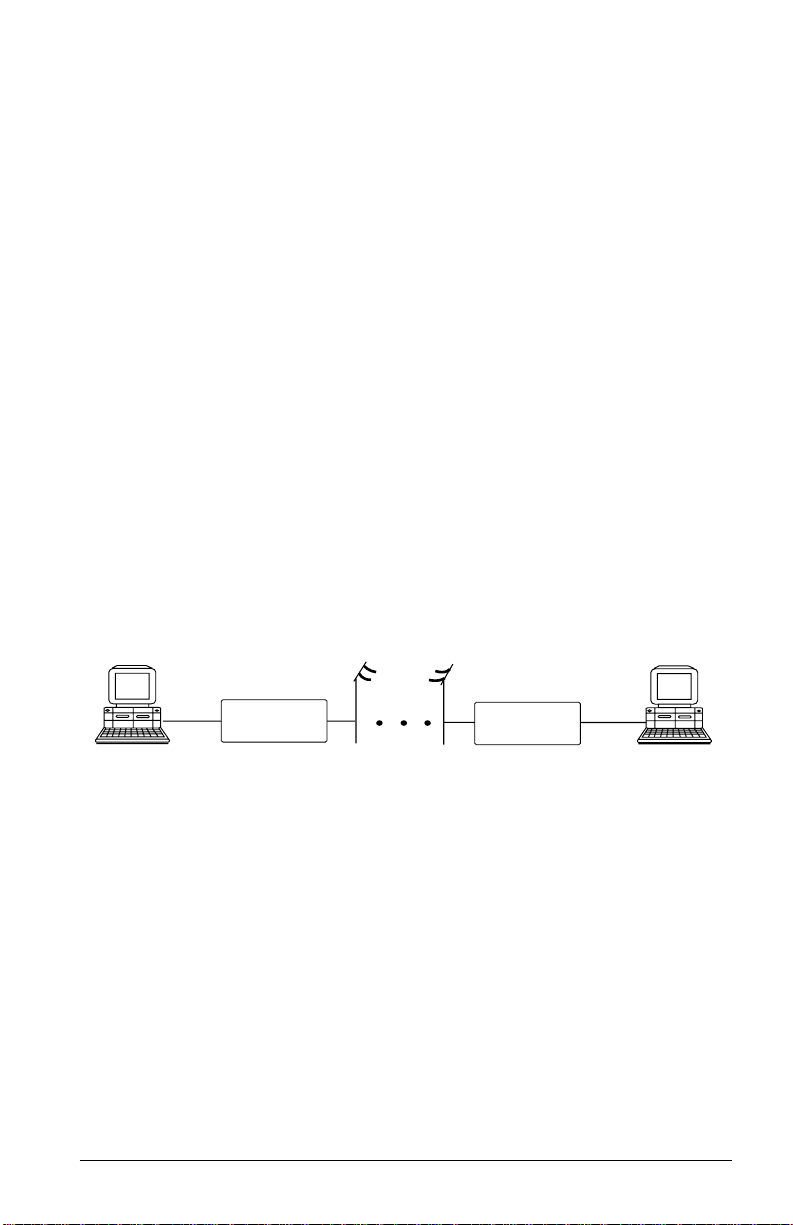
Modem
Modem is a compound word of MOdulator and DEModulator. A modem is used
for computer communications. Refer to Fig. 2.1 for a standard modem setup and
application.
Modem
Fig. 2.1: Modems are used in computer communications.
A modem translates computer data to analog signals (modulation) that can travel
through the telephone network and reach another modem. The remote modem
translates the analog signal received back into data (demodulation) and sends the information to the receiving-end computer. Modems are telephones for computers,
what they use to talk to each other.
Modem
DTE and DCE
DTE and DCE are terminologies used in data communication. DTE stands for
Data Terminal Equipment and DCE stands for Data Circuit terminating Equipment (Data Communication Equipment). Referring to Fig. 2.1, the computer or
terminal is the DTE and the modem is the DCE.
2–1
Page 28

RS-232C or EIA-232D/E
RS-232C is the Recommended Standard (RS) of the Electronic Industries Association (EIA), defining the serial communication interface between a DTE and a DCE.
The 232 is basically a serial number for the defined standard. Sometimes it is necessary to redefine a standard, or to revise it. The most commonly used r evision of the
RS-232 standard is the "C" revision. For the "D" revision, the pr efix was changed to
EIA. Except for a few added, but not commonly used signals, there is no practical
difference between the "C" and "D" revisions. Ther e is now a new revision with the
”E“ suffix. The RS-232C standard is equivalent to the ITU-T V.24 and V.28 standard. Also refer to the Modem Standards and Speeds section below.
Serial Port
A serial port is the serial data connector together with its internal circuit on the DTE
or DCE with electrical and mechanical characteristics according to RS-232C. Since
some signals are going from the DTE port to DCE port, and some signals are going
in the other direction, the signal pin is a transmitter on one port and a receiver on
the other. The DTE serial port is different from the DCE serial port in terms of signals on the connector pins. There are also mechanical differences in terms of male
(with pins) or female (with holes) connectors.
Serial RS-232C Cable
A serial RS-232C cable is used to connect a DTE port to a DCE port. Do not use a
null-modem cable (which may be used to connect two DTEs directly with each other through their serial ports). A normal RS-232C connector has 25 pins and a normal RS-232C cable has 25 wires. Many signals in the RS-232C are not used in
common applications and a 9-wire RS-232C cable is sufficient in most applications.
The PC-A T's serial port has only 9 connector pins, eliminating the unnecessary pins.
For high-speed DTE-DCE comunication, use a low-capacitance cable, as short as
possible.
Synchronous and Asynchronous Communication
There are two kinds of serial data communication. One is called synchronous and
the other is called asynchronous. In synchronous communication, data is transmitted and received bit by bit and is timed by an accompanying clock signal. In asynchronous communication, data is sent character by character (or octet by octet), and
the idle time between characters is variable. No clock signal is sent; character timing
is recovered from the data itself.
2–2
Page 29

A PC's COM1 and COM2 are asynchronous serial ports. Most PCs' and Unix systems' serial data communications are asynchronous. The serial data communication
on an IBM mainframe or mini is synchronous.
UART
A UART (Universal Asynchronous Receiver Transmitter) is the device used in a DTE
or DCE for asynchronous data reception and transmission. The standar d UAR T device used in PCs is of the NS16450 type. For high-speed serial data transfers (38400
bps and up), the PC may not serve the UART fast enough and data may get lost. In
this case, a UART with data buffer is needed, such as the NS16550A type device.
Modem Standards and Speeds
The ITU-T or ITU-TSS (International Telecommunications Union - Telecommunications Standardization Sector), is the international standard-making body for telecommunications. They draft recommendations. The recommendations they make
for modem applications have a "V" prefix and are called V-series recommendations.
The commonly used ITU-T modem standards for 2-wire dial-up line are:
Standard
V.34 28 800 - 2 400
V.32bis 14 400 / 12 000 / 7 200
V.32 9 600 / 4 800
*
V.22bis
V.22 1 200
V.21 300
V.23 1 200 / 75
*. bis is the old French word for second.
In the USA, Bell Systems used to create de facto standards such as Bell 212A for
1200 bps modems and Bell 103 for 300 bps modems. Everyone follows the ITU-T
standards now for newer and higher-speed modems.
ZyXEL 2864 series modems support all the above mentioned modem standards and
are compatible with existing modems.
Speed (bps)
2 400 / 1 200
Type of Telephone Line
The commonly used phone service is a 2-wire dial-up line. There are only two wires
connecting the modem to the phone company's central office. The same two wires
are used for DC current feeding, ringing, dialing, on/off-hook monitoring, and sig-
2–3
Page 30

nal transmission in both directions. This is the type of phone service most people
have in their home or office. Since the same two wires are used for both transmitting
and receiving signals, an echo of the transmitting signal will also be received and it
is the modem receiver's task to remove the echo before demodulation.
Leased-line phone service is also available from phone companies in a 4-wire form.
Here, both the transmitting and receiving signals each use a separate 2-wire pair and
thus no echo problem will result. Normally, no DC current feeding, ringing, or dialing function is provided on a leased line.
There is also the 2-wire leased line which is a permanent 2-wire connection.
Intelligent Modem
Formerly, modem functions, settings, and operations were simple and everything
was controlled by manual switches, either internal or external, or by wire-strapping
settings. No computer control was provided.
All of an intelligent modem’s functions, including dialing and answering, are controllable by the computer or terminal it is connected to by means of the same RS-232
serial interface used for data connection.
An intelligent modem operates in one of two states - the command state or the data
state. In command state, the modem interprets data received from the serial interface
as commands and sends back an action result in response. In data state, the modem
modulates the data received from the serial interface and sends the demodulated data
to the serial interface as received data. The user needs to know whether the modem
is in the command state or data state and how to switch it.
ISDN
The normal telephone network PSTN (Public Switched Telephone Network) transmits voice band analog signals from end to end. A modem is needed at each end to
transmit digital data. The digital telephone network ISDN (Integrated S ervices Digital Network) transmits digital data from end to end, thus no modem is needed to
transmit data. Instead, an ISDN telephone is needed at each end to translate voice
signals to and from digital data for ISDN digitized voice data transmission.
ISDN TA
ISDN has a digital interface at the customer site. An ISDN TA (T erminal A dapter)
will adapt the user terminal’s interface, usually an asynchronous or synchronous serial interface, to the ISDN digital interface, usually the S- or T-interface. With an
ISDN TA a user connects a computer/terminal to the ISDN telephone line in the
same way as he/she uses a modem to connect a computer/terminal to the PSTN telephone line.
2–4
Page 31

BRI
BRI, Basic Rate Interface, is the ISDN service provided to a normal home or office.
It consists of 2B+D data channels. A D channel offers a speed of 16Kbps for signaling information transmission. Each B channel is for user data transmission at
64Kbps. Each B channel can be used independently for voice or data transmission.
A user can place two independent calls through a BRI interface simultaneously.
U- or S-Interface
ISDN signal transmission is digital from end to end. At every interface point there
is a specified signal format. Equipment at every interface point needs to have signal
transmission/reception conform to the specified signal format. At the customer site,
the interface point for terminating the ISDN line connection from the CO (Central
Office) is called the U-interface. A network terminator NT1 terminates the ISDN
U-interface and converts it to the S-interface for internal ISDN equipment connection. Non-ISDN capable equipment can use an ISDN TA to connect to the S-interface.
In North America, the NT1 U-interface device is the user’s responsibility. The user
can either install an NT1 to get the S-interface for internal ISDN equipment connections, or have an ISDN TA to directly adapt to the U-interface. In Europe, the
telephone company installs the NT1 U-interface device at the customer site. The
user only needs to have the ISDN TA to adapt to the S-interface.
AT Command Set
The A T command set is the industry de facto standard used to control a modem in
command state. It got its name from the fact that every command line has a prefix AT .
AT commands were first used in the Hayes Smartmodem
other modem manufacturers and communication software writers. The original set
of AT commands such as dialing, answering, etc., is used by everyone and is standardized. The AT command set is extended by each modem manufacturer for control
of ever-increasing modem functions and capabilities. This extended or enhanced
command set is not standardized whatsoever.
The AT command set is used only with an asynchronous serial data interface. To
send an AT command to a modem the connected computer must be running a terminal software. ZyXEL has defined a set of extended AT commands to support
many of its unique functions and features.
2–5
and hence adopted by
Page 32

V.25bis Command Set
V.25bis is a set of auto-dialing commands defined by the ITU-T. V.25bis supports
both synchronous and asynchronous data interfaces and is mainly used in Europe
and in IBM mainframe or mini-environments which use synchronous communication.
Error Correction
In synchronous data communication, data is checked and corrected in the host by
the so-called "link layer protocol" to ensure data integrity. Normally, no data checking is provided in the host for asynchronous data communication. However, file
transfer protocols which include error checking are available with asynchronous
hosts.
Nowadays, intelligent modems incorporate error correction protocols inside the modem for asynchronous data communication and it is transparent to the host. The
modem packs the asynchronous data characters into blocks. The data is transmitted
as synchronous data between the modems. The data blocks are error checked at the
remote end, and an erroneous block is retransmitted.
The commonly used error correction protocols are MNP and V.42 protocols.
Data Compression
Intelligent modems use redundancy removing methods to reduce the number of
data bits actually sent for asynchronous character transmission. The full character
data is recovered at the other end, thus the total throughput of the modem data
transmission is increased.
The data compression protocols commonly used by modems are MNP class 5 and
V.42bis. (See definitions below.)
Data compression works on redundancy removing and its efficiency is dependent on
both the compression algorithm and data statistics.
MNP Protocols
MNP (Microcom Network Protocol) is a set of protocols first introduced by Microcom, Inc., and later used by many modem manufacturers. It consists of many
classes. Classes 1 to 4 are for error correction, and class 5 is for data compression.
MNP class 1 and 2 are obsolete. Normally class 4 is used for error correction and it
uses class 3 internally.
MNP class 5 is a data compression protocol with a maximum efficiency of 2 to 1.
MNP-5 is used with MNP-4 for error correction.
2–6
Page 33

V.42bis and V.42
V.42bis and V.42 are data compression and error correction standards set by the
ITU-T. V.42bis has a better data compression efficiency than MNP-5 and is a more
advanced compression scheme. V.42bis is used with V.42 for error correction.
Xmodem, Ymodem, and Zmodem
These are file transfer protocols. They do error checking and ensure data integrity of
the file transferred. Some variations of these protocols also appear , like Xmodem-1k,
Ymodem-G, etc.
The "G" types of protocols do not include error checking. They allow very high
throughput rates, but can be safely used only when the modems use MNP4 or V.42
error protocols and there is no speed overrun on the computer's serial port.
Whenever possible, we recommend the use of Zmodem for added security and high
flexibility . Consult your communications program manual for more information on
transfer protocols.
Fax and Facsimile
Fax is the abbreviation for facsimile. There ar e four major parts in a normal facsimile
machine, the scanner, encoding and decoding device, modem, and printer. Before a
page can be sent, it is first scanned, the bit-mapped data is encoded with data compression, and then it is transmitted across the phone line by an internal modem
module. The remote facsimile receives the data with its internal modem, decodes it
back to bit-mapped image data and prints it on paper.
Fax Card
A fax card is an internal plug-in card which must be specifically designed to fit into
your type of computer. It has the modem function of a facsimile machine. A computer loaded with fax software can send or receive faxes through a fax card. The computer is used as the input and output parts of a facsimile machine and the fax card is
used as the transmit/receive part and may also do the encoding/decoding function,
depending on the design. The computer controls and communicates with the fax
card through a set of proprietary hardware and software interfaces which are different for each fax card manufacturer.
2–7
Page 34

Modem as a Fax
Modems can also be designed to include a fax transmitting and receiving function
similar to a fax card. Since the modem's interface with the computer is the standard
serial RS-232 interface, this interface is used for both modem and fax operations.
Since the data throughput of a serial RS-232 interface is limited, only compressed
fax image data should be carried through this serial interface. Fax image coding and
decoding must be done in the computer. M odem/F ax, also called faxmodem, can be
either an external stand-alone unit or a plug-in card. External stand-alone units can
be connected to any computer with a standard RS-232 serial port.
EIA Class 1 and Class 2/2.0 Fax Commands
The EIA class 1 and class 2 fax commands are a set of A T fax commands defined b y
EIA/TIA (T elecommunications Industry Association) for controlling faxmodems from a
computer through the serial RS-232 interface. Faxmodems and fax software supporting
this standard will work together . Class 1 commands contr ol the details of ho w the modem does on-line negotiation and control jobs whereas Class 2 commands allow the modem to do many negotiations automatically . The Class 1 command set is also called the
TIA-578 standard. Several revisions of the class 2 standard exist. I mplementations conforming to different revisions may not work together . A formally approv ed version is the
Class 2.0 command set, also called the TIA-592 standard.
Autodetection of Fax or Data Call
Fax and data modems have different handshaking signal sequences at the beginning
of a call as specified by the ITU-T. It is possible to automatically detect whether an
incoming call is from a modem or a fax device by testing and recognizing its initial
handshaking sequence. A modem with this capability can make a computer process
both data and fax calls on the same phone line. An example is that a BBS (Bulletin
Board System) can also receive faxes. Z yXEL modems can automatically detect data
and fax calls. ZyXEL also includes a fax reception and printing program to allow a
BBS to receive faxes and print them out.
Caller ID
Normally called Caller Number Delivery (CND), this is a service available from
phone companies in several parts of the USA and some other countries. With this
service, the phone company sends calling party information along with the ring signal to the called party. The major part of this information is the telephone number
of the calling party or caller ID. ZyXEL modems can detect and report caller ID.
Note that different countries have different caller ID schemes. Please check whether
the scheme used in your country is supported by the modem.
2–8
Page 35

Distinctive Ring
This is a service available from some phone companies in some areas of the USA and
elsewhere. You can have several phone numbers on the same subscriber phone line.
The phone company sends a different ring signal for each phone number assigned
to the same line. You can have your phone equipment answer only a certain type of
ring corresponding to a certain phone number. Z yXEL modems can be set to answer
on one or a combination of four types of ring signals. The problem is that every
country may have a different specification for different ring types.
Digitized Voice
Modems with digitized voice capability can digitize an incoming voice message with
the computer storing it as a file. The modem can also playback a recorded digital
voice message either locally or to the line as an announcement.
Digital voice messages need speech compression to reduce the storage requirements.
This speech compression is done in real time by the modem and it does the decompression during playback. A simple voice capability using an ADPCM (Adaptive
Differential Pulse Code Modulation) algorithm can reduce the speech data rate to
1/2 or 1/3 of the original rate. An advanced algorithm is needed to reduce the speech
data rate even further.
Cellular Modem
A cellular modem is a data modem that can be used on the analog cellular mobile
phone system. With the rising popularity of notebook computers this is of increasing
importance for people on the move.
There are two kinds of phenomena in the cellular mobile phone system that are particularly bad for modem data communications. One is called cell hand-off, meaning
that a cellular phone is instructed to change the radio link from one cell site to another when travelling across a site boundary. The radio link will be temporarily interrupted and most modems will retrain or even hang up. When a cellular phone is
instructed by the cell site to change transmitting power, it will cause similar problems. The other particularly annoying phenomenon is multipath fading. Here, a
moving cellular phone will experience periodical fading or drop-out of the radio signal. This causes high data error rates and low throughput.
ZyXEL developed cellular modes using its proprietary data pump that handles the
cell hand-off and multipath problems. The V.42 link layer protocol with selective reject greatly improves data file transfer throughput in high error situations.
2–9
Page 36

Automatic Redial / Call Hunting
Most modems will automatically redial a telephone number several times if a connection could not be established on the first try. The modems of the 2864 series also
offer the ability to do cyclic redials of a set of up to 10 different numbers.
Modem Approval and Legal Matters
In some countries the PTT authorities require modems to conform to a set of specific rules, e.g., transmitting signal level limitation, line circuit isolation, or restriction of the behavior of modems during automatic redial. Modems must receive an
official approval within those countries to be used legally. ZyXEL provides specifically designed models which have received such an approval. Check your local distributor to find out details about approved models.
2–10
Page 37

Chapter 3
MODEM INSTALLATION
This chapter describes the panel function of the 2864 series modems and serves as
their installation guide.
External Modems
A shielded RS-232 cable is required to ensure compliance with FCC P art 15, and it
is the responsibility of the user to provide and use a shielded RS-232 cable.
Make sure your installation site is clean and well ventilated. The ventilation slots of
your ZyXEL modem located on the top, the sides, and the bottom should not be
covered and should allow free movement of air.
Elite 2864
The Elite 2864 model is a V.34 modem with V.34/fax/voice capability and is upgradeable to include ISDN capability. LEDs are used for all display purposes.
Elite 2864 Front Panel
Fig. 3.1 shows the front panel of the Elite 2864. There are 21 LED indicators and
two key switches.
D / V
O / A
ZyXEL
More Than A Modem
V34 V32b AA CD
Elite 2864
V.34/FAX/VOICE
FAX
TST
PWR
DSR
DTR
POL
RTS
PSL
PPE
Fig. 3.1: The Elite 2864 front panel
3–1
SPVO
CTS
PER
ECRXDTXD
OH
PCPPRP
ORG
V34
Page 38

LED Indicators
PWR PoWeR on indicator; lights up when the modem‘s power is ON.
TST TeST indicator; lights up when the modem is in test mode.
FAX FAX indicator; lights up when modem transmits or receives a fax.
VO VOice mode indicator; lit when modem is in voice mode.
SP * Serial Port active indicator; lights up when modem is using the se-
rial port for DTE communication.
PRP * PRinter Parallel port active indicator; lights up when modem is us-
ing the parallel port to drive a printer for fax printing.
PCP * PC Parallel port active indicator; lights up when modem is using the
parallel port to communicate with a PC's bidirectional parallel port.
Note: *Only one of the SP, PRP, or PCP LED indicators will light up at one time.
OH Off-Hook indicator; lit when modem is on-line or in off-hook state.
It is turned off when modem is off-line or in on-hook state.
EC Error Control indicator; lights up when modem is operated in an er-
ror controlled mode like MNP4 or V.42. Data compression mode
(V.42bis or MNP5) implies error control mode. Also used as retransmission indicator; blinks when retransmitting.
SQ Signal Quality indicator; lights up when signal quality is good;
flashes when it is on margin. At power on it flashes to indicate an
error condition; refer to the Diagnostics Chapter (18) for details.
ORG ORiGinate mode indicator; when lit, the modem will operate in orig-
inate mode if it is manually made to go off-hook by toggling the
DATA/VOICE switch. If not lit, the modem will be in answer mode.
V34 V.34 (or supported V.fast mode) indicator; flashes alternatively with
the V32b indicator when the modem is in a handshaking procedure.
V32b V.32bis or V.32 mode indicator; flashes when dialing or before
handshaking.
The combinations of the V34 and V32b LEDs indicate the following modes:
V34 V32b Mode
OFF OFF V.22bis, V.22 and other modes with speed less than 9600bps
OFF ON V.32bis or V.32
ON OFF V.34 (or supported V.fast mode, if any)
ON ON ZyX mode
3–2
Page 39

AA Auto Answer indicator; lights up when the modem is in auto answer
mode; flashes when modem rings.
CD Carrier Detect indicator; lights up when a valid carrier is detected
present on the line.
TXD Transmit Data indicator; lights up when your DTE/computer trans-
mits data to the modem.
RXD Receive Data indicator; lights up when your DTE/computer receives
data from the modem.
The following four indicators have different meanings depending on whether the
modem is connected to a DTE (computer or terminal) through either of the parallel
or serial interfaces (SP or PCP is ON, DTE mode) or whether the modem is connected to a printer through the parallel port interface (PRP is ON, printer mode).
DTR
POL
DSR
PSL
RTS
PPE
CTS
PER
DTE mode: Data Terminal Ready indicator; lights up when the DTE
or computer indicates that it is ready for communication by raising
the corresponding RS232 signal.
Printer mode: Printer On Line indicator; indicates the status of the
printer’s "Select" (SLCT) signal. It lights up when the printer is selected and is available for data transfer.
DTE mode: Data Set Ready indicator; lights up when modem is
ready for communication.
Printer mode: Printer SeLect signal; indicates the signal status of
"-Select In" from modem to printer. It lights up when printer is enabled to input data.
DTE mode: Request To Send indicator; indicates the signal status of
RS232 signal RTS from DTE. RTS is used for hardware flow control
in asynchronous data transmission.
Printer mode: Printer Paper End indicator; lights up when the printer is out of paper. It indicates the signal status of "PE" from the printer.
DTE mode: Clear To Send indicator; lights up when modem can accept data for transmission. It indicates the signal status of RS232
signal CTS.
Printer mode: Printer ERror indicator; lights up when an error condition exists in the printer, e.g., out ot paper or not on-line. It indicates the signal status of "-Error" from the printer.
3–3
Page 40

Front Panel Switches
There are two toggle switches on the Elite 2864 front panel.
D/V (DATA/VOICE)
A toggle switch that switches the modem on-line (off-hook DA T A mode) or off-line
(on-hook, Voice or Talk mode, the telephone set is connected to the line). The OH
LED indicator will be turned on and off by this switch. If S35 bit 4 is set
(S35.4=1), pressing this switch will make the modem go off-hook and dial the default number.
O/A (ORG/ANS)
A toggle switch that determines the mode, Originate or Answer, the modem will operate in, if made go off-hook by pressing the D/V switch. The ORG LED indicator
will be turned on and off by this switch.
Note: This switch only determines modem operation mode if made go off-
hook manually. The ATD or ATA command will automatically determine the mode.
Warning: If this switch is pressed while the modem is turned on, the modem
will jump into a special kernel program which allows the user to upload a new firmware into the modem from a connected DTE. If this
is not what you intended, turn off the modem and then turn it on
again to return the modem to normal operation.
Elite 2864 Rear Panel
Fig. 3.2 shows the Elite 2864 rear panel.
POWER
JACK
Fig. 3.2: The Elite 2864 rear panel
Parallel
3–4
DTE
Serial
LINE PHONE
Page 41

The following table explains the connectors on the rear panel:
POWER
JACK
PARALLEL Parallel port DB25 male connector for connection to a PC's parallel
SERIAL Serial port DB25 female connector for connection to the serial port
LINE Dial-up line RJ11 terminal jack; for connection to a 2-wire dial-up
PHONE RJ11 terminal jack; for connection to a telephone set.
Input terminal for power adapter. There is no power switch on the
modem.The power switch on the power adapter will turn off the
power adapter and shut off power to the modem. Always turn off the
power adapter before connecting or disconnecting power. For additional safety against possible damage, don’t turn on the power with
the parallel port connected to a piece of equipment which is under
power.
port or a printer's Centronics compatible port.
of a DTE (computer/terminal).
line on the wall jack.
Connecting the Elite 2864
Power Connection
Connect the power plug from the adapter to the power jack. Connect one end of the
power cord to the power adapter and plug the other end into an electrical outlet.
When you connect your 2864 to the power line, make sure you only use the ZyXEL
power adapter that is supplied with this unit. Use of another adapter may not allow
your modem to operate and could result in serious damage to the unit. This adapter
is rated for direct connection to an AC power outlet.
Turn off the power on both the computer and the modem before making connections. Then connect the modem according to the rear panel labels.
Warning: Always turn off the power switch on the power adapter before con-
necting to the modem power jack. Never plug or unplug modem's
power jack with the power adapter turned on as this may damage
the modem.
Computer and Printer Connection
The modem has both a parallel port and a serial port connector. You can connect the
serial port connector to your computer's serial port or connect the parallel port connector to your PC's bidirectional parallel port or you can connect both ports to your
PC's serial and parallel port. You can also connect the serial port to your PC's serial
port, and the parallel port to a laser printer. If you have the modem set up for auto
3–5
Page 42

Page 43

Elite 2864L Front Panel
The Elite 2864L's front panel is exactly the same as the Elite 2864's except that the
Elite 2864L has an LL LED indicator instead of the VO indicator.
LL Leased-Line indicator; lights up when the modem is operating in the
leased-line mode.
Elite 2864L Rear Panel
The Elite 2864L has a LEASED line jack and a DIAL-UP line jack. The LEASED
line jack is a JM8 leased-line connector for a 2 or 4-wire leased-line connection. Pin
assignments for the JM8 jack are listed in appendix B. Pins 1 and 2 are for 2-wire
leased-line connections. For 4-wire leased-line connections, pins 1 and 2 are for
transmission and pins 7 and 8 are for receiving. The DIAL-UP line connector is an
RJ11 connector for dial-up line connections. A normal telephone cable will connect
this jack to a telephone line wall jack. There is no PHONE jack for the E lite 2864L
model.
Connecting the Elite 2864L
Connect the power, serial port, and parallel port as described above for the Elite
2864 model. Connect the dial-up line to the DIAL-UP jack and the leased line to
the LEASED jack. If no leased line is used, just leave the jack unconnected.
Turning on the Elite 2864L
Please refer to Turning on the Elite 2864 on page 3–6.
Elite 2864I and Elite 2864IU
The Elite 2864I is the model with an ISDN S-interface RJ45 connector. The Elite
2864IU is the same model, but with an ISDN U-interface RJ45 connector. The basic panel description for the Elite 2864I and the Elite 2864IU is similar to that of
the Elite 2864. Please refer to the separate 2864I ISDN modem user’s manual for
details.
Supreme 2864L
The Supreme series model has a LCD display front panel. The S upr eme 2864L supports 2/4-wire leased line in addition to the normal dial-up line support.
3–7
Page 44

Supreme 2864L Front Panel
Fig. 3.3 shows the front panel of the Supreme 2864L. Ther e are 10 LED indicators,
a 20×2 LCD display, and four directional key switches.
Fig. 3.3: The Supreme 2864L front panel
The 10 LED indicators are labeled as PWR, OH, AA, DTR/POL, RTS/PPE, TXD, RXD,
SP, PRP, and PCP. The meaning of these LED indicators can be found on page 3-2
to page 3-3 where the LED indicators of the same label are explained for the Elite
2864 model.
There are four arrow keys on the front panel for panel operations. They allow intuitive menu tree operation and status display. Please refer to chapter 5 (2864 QUICK
START) for details regarding the menu key operations.
Supreme 2864L Rear Panel
Fig. 3.3 shows the rear panel of the Supreme 2864L. The rear panel is similar to the
Elite 2864’s rear panel shown in , except that the Supreme 2864L has three phone
jacks. Besides the dial-up line RJ11 jack and the telephone connection RJ11 jack,
there is also a JM8 leased-line jack. Each rear panel connector’s explanation can be
found starting on page 3-4 where the explanations for the Elite 2864’s rear panel ar e
listed. The LEASE D LINE jack is a JM8 type jack with pin assignments listed in
appendix B.
Fig. 3.4: The Supreme 2864L rear panel
3–8
Page 45

Connecting the Supreme 2864L
Please refer to the section Connecting the Elite 2864 on page 3–5. The descriptions
therein also apply to connecting the Supreme 2864L. The Supreme 2864L has an
additional leased-line jack for 2/4-wire leased line connection. Leave the leased-line
jack unconnected if the leased line is not used.
Turning on the Supreme 2864L
Turn on the power switch on the power adapter to turn on the modem. The Supreme 2864L will perform a series of diagnostic tests while a message is shown on
the LCD panel. For a more detailed description of these diagnostic tests, please refer
to chapter 18 (DIAGNOSTICS).
After performing the diagnostic tests, your Supreme 2864L will display the current
modem settings on the front LCD panel as shown in Fig. 3.3. Your Supreme 2864L
is now ready for use.
LINK OPTION
V34 28800 V42b DL
D R O A 115200 AS
DATA FORMAT
DTE RATE
ANSWER MODE
ORIGINATE MODE
REDIAL LAST NUMBER
DIALING
Fig. 3.5: The Supreme 2864L idle screen after powering up
LINK SPEED
ERROR CONTROL
LINE TYPE
Supreme 2864I and 2864IU
The Supreme 2864I is the model with an ISDN S-interface RJ45 connector . The Supreme 2864IU is the same model, but with an ISDN U-interface RJ45 connector.
The basic panel description for the Supreme 2864I and 2864IU is similar to that of
the Supreme 2864L. Please refer to the separate 2864I ISDN modem user’s manual
for details.
3–9
Page 46

Omni 288P and Omni 288S
The Omni models are V.34 modems with V.34/fax/voice capability , but without the
ISDN capability. The Omni 288P includes a parallel port as DTE interface, the
Omni 288S includes a serial port as DTE interface.
Omni 288P Front Panel
Fig. 3.3 shows the front panel of the Omni 288P. There are 13 LED indicators and
one key switch.
Fig. 3.6: The Omni 288P front panel
The 13 LED indicators are labeled as V34, V32b, AA, CD, TXD, RCD, DTR/POL,
DSR/PSL, PRP, PCP, EC, SQ, and OH. Explanations for the meanings of these LED
indicators can be found in the table beginning on page 3-2 where the LED indicators of the same label are explained for the Elite 2864 model.
There is only one push-button switch labeled D/V (DATA/VOICE) on the modem’s
upper case near the lower right corner . Please refer to the description on page 3-4 for
an explanation of the switch’s use.
Omni 288S Front Panel
Fig. 3.3 shows the front panel of the Omni 288S. Similar to the Omni 288P, there
are 13 LED indicators and one key switch. The LED indicators are labeled the same
3–10
Page 47

as on the Omni 288P except that the Omni 288S has two LED indicators labeled
RTS and CTS instead of PRP and PCP as found on the Omni 288P.
Fig. 3.7The Omni 288S front panel
The meaning of the Omni 288S LED indicators can be found in the table beginning
on page 3-2 where the LED indicators of the same label are explained for the Elite
2864 model.
Omni 288P Rear Panel
Fig. 3.8 shows the rear panel of the Omni 288P.
Fig. 3.8: The Omni 288P rear panel
The table below explains the switch and connectors on the rear panel according to
their labels:
ON/OFF The power switch; up position is ON, down position is OFF.
POWER Input terminal for the power adapter, connects to an external AC or
DC 12V-16V, 1A adapter.
AUX
RS232
A RJ45 Jack for an auxiliary RS232 serial port; may be used to issue AT commands and receive responses for monitoring purposes.
3–11
Page 48

TO DTE This is a parallel port DB25 male connector for connecting to a PC’s
parallel port or a printer’s Centronics compatible port.
MIC Microphone jack to plug in an external microphone. Used for voice
recording purposes.
SPK Speaker jack to connect an external 8 Ohm speaker. An external
speaker may be connected to replace the internal speaker and provide better sound quality.
LINE Dial-up line RJ11 terminal jack; connects to a 2-wire dial-up line
wall jack.
PHONE RJ11 terminal jack to connect a telephone set.
Omni 288S Rear Panel
The Omni 288S’s rear panel is identical to the Omni 288P’s except that the connector labeled TO DTE is a DB25 female connector which connects to a DTE’s serial
port and there is no AUX RS232 connector.
Connecting the Omni 288P
Turn off the power on the computer (if possible) and the modem before making connections. Then connect the modem according to the rear panel labels.
Power connection
Use only the ZyXEL po wer adapter that is supplied with this modem. Using any other power adapter may cause serious damage to the modem and void warranty.
Connect the power cord from the power adapter to an AC electrical outlet and connect the round power plug from the adapter to the power jack on the modem. This
completes the power connection for the Omni 288P.
Warning: Always turn off the power switch on the modem before connecting
the power adapter to the modem. Avoid plugging or unplugging the
modem's power jack with the power switch turned on as this may
damage the modem.
Computer and Printer Connection
The modem has a parallel port. Y ou can connect this parallel port connector (labeled
TO DTE) to your PC's bidirectional parallel port for DTE communication. A normal
25-wire male to female shielded RS-232 cable can be used for this connection. You
can also connect the modem ’s parallel port to a laser printer for direct fax reception
and printing operation. A normal PC printer cable together with a female DB25 to
female DB25 gender changer can be used for this connection.
3–12
Page 49

If the modem ’s parallel port is always connected to a laser printer for fax printing, a
computer/terminal can connect to the modem’s AUX RS232 serial port for issuing
A T commands and r eception of r esponses. This is good for configuration and monitoring operation without disconnecting the laser printer. This AUX RS232 serial
port is intended only for AT command and r esponse ’s transmission; it is not intended for DTE data transmission. Auto speed detection is not supported on this AUX
RS232 port. Only the speeds 38400 bps and 19200 bps are supported on the AUX
serial port, 38400 bps being the default speed. The asynchronous character format
accepted on the AUX RS232 port is 8N1 (8 data bits, no parity, one stop bit).
A RJ45 to DB25F connector adapter is needed to convert the RJ45 AUX RS232
port to a normal DCE DB25 female serial port connector. The following table lists
the conversion connections:
Signal Name Pin No. on DB25F Pin No. on AUX RJ45
TXD 2 1
RXD 3 8
RTS 4 2
CTS 5 7
GND 7 3 and 6
DSR, CD, DTR 6, 8, 20 tied together -
Phone Line Connection
Use the telephone cable supplied to connect the modem's LINE jack to the telephone line wall jack. You can also connect a telephone set to the modem's PHONE
jack in case you need the telephone for voice communication. A telephone set is not
needed for the modem's data, fax, and voice mail communication. The telephone set
may also be used to record or to playback voice messages.
Connecting the Omni 288S
Please refer to the above description for connecting the Omni 288P. The descriptions for
the power and phone line connection also apply to the Omni 288S. The descriptions for
connection to a computer or a printer through the parallel port do not apply , because the
Omni 288S has a serial port for connection to a computer/terminal’s serial port only.
There is no possibility to connect to a printer by parallel port.
Turning on the Omni 288P or Omni 288S
Turn on the power switch on the modem to turn on the modem. The modem will
do a self-test each time it is turned on. The SQ LED will flash if the power-on selftest fails. For a more detailed description of the diagnostic tests, please refer to
chapter 18 (DIAGNOSTICS).
3–13
Page 50

3–14
Page 51

Chapter 4
MODEM OPERATION
Parallel or Serial Port Operation
The 2864 models provide both a parallel port and a serial port for DTE connection,
but only one out of three connection modes may be active at any time. The available
modes are:
• SP: Serial port mode;
• PRP: Printer parallel port mode;
• PCP: PC parallel port mode.
Only when a port is actively driven and/or terminated externally may that port be
active, i.e., the connected device must be turned on and must drive the port. An exception to this is the serial port. The modem defaults to the serial port if no active
parallel port device is connected whether an active serial DTE is connected or not.
The modem makes its port selection based on the serial port DTR signal. If it is ON,
the modem defaults to serial port (SP) mode; if it is OFF, the modem seeks for an
active parallel port device. If an active PC parallel port is connected, the modem will
operate in PCP mode; if an active printer is connected, the modem will operate in
PRP mode. If no active parallel port device is connected, the modem will default to
SP mode.
If both the modem's serial and parallel ports are actively connected and the parallel
port is connected to a PC parallel port, the modem makes the port selection based
on the serial port DTR signal. The serial port DTE can control the modem's active
port through its DTR signal. If both the modem's serial port and parallel port are
actively connected and the parallel port is connected to a printer, the modem also
makes its port selection based on the serial port DTR signal. If the serial port DTR
signal is OFF, the modem operates in PRP mode; if the serial port DTR signal is
ON, the modem operates in SP mode. In Class Z mode operation for fax receiving
and printing(explained in chapter 15), the modem will temporarily switch to PRP
mode to print incoming faxes.
If you use a serial port DTE that does not provide a DTR signal, make sure that no
parallel port device is connected to the modem and that the modem defaults to serial
port mode. Y ou also need to set the modem DTR setting permanently to ON ( &D0).
4–1
Page 52

PC Parallel Port Operation
If the modem's parallel port is connected to a PC's parallel port, the PC can communicate with the modem through the parallel port link. Be sure that your PC has
a bidirectional parallel port. The modem's parallel port will not work with the old
unidirectional parallel port. You need not have EPP nor ECP capability on your parallel port.
Using the parallel port, the PC sends and receives 8 data bits at a time to and from
the modem. However, for your communications software package the modem appears to be a serial device. A device driver has to be installed to shield the comm software from the actual difference in the hardware setup. The parallel port link accepts
hardware and/or software flow control, but setting the serial port speed is only a
dummy function; it has no effect on the parallel link.
The parallel port link only supports asynchronous mode communication. Synchronous mode is not supported. The modem buffers the data to and from the PC, direct
asynchronous mode is not supported.
Parallel Port under Windows
You need to install a driver in order to use your Windows comm or fax program.
ZyXEL has developed Windows parallel port drivers for which instructions are included on the program disk containing the drivers.
Parallel Port under DOS
When the DOS comm or fax program directly accesses the serial port, it is not possible for a driver program to intercept the access and redirect it to the parallel port.
However, the access can be redirected to the parallel port if a comm or fax program
accesses the serial port through a fossil driver, by changing the fossil driver. A fossil
driver is included on the companion software disk.
Parallel Port Speed Limit
Although there is no speed limitation on the parallel port data transfer similar to the
serial port, some parallel port I/O read/write operations need to be done for every
data byte transfer across the parallel port link. This limits the maximum parallel port
transfer speed. The operating system and/or the comm/fax program also does a lot
of overhead processing for data received or transmitted as well as for port maintenance. This also limits the maximum speed with which a PC can manage data passing through the parallel port. For the Windows user interface, or the DOS FOSSIL
driver, the latter is even a dominating factor. The good point about the parallel port
is that data overruns will never occur , no matter ho w slow the the softwar e retrieves
data from the port. This is important in the Windows environment.
4–2
Page 53

ZyXEL Parallel Port Adapter
ZyXEL is developing a special parallel port adapter that will make parallel port transfers much faster between a PC and the Elite 2864. The speed limitation in this case
will be determined by how fast and how efficient the PC software program can handle the data.
The operation instructions for this special parallel port adapter are included in the
adapter manual. Check ZyXEL's announcements for availability, which is expected
to be within a few months of the 2864's introduction. Refer to chapter 21 for information on the ZyXEL serial/parallel I/O adapter.
Using the Microphone and Speaker Jacks
On the right side or back of the modem, there are two jacks for external microphone
and speaker connections. The speaker jack is capable of directly driving an 8 ohm
speaker. When an external speaker is plugged into the speaker jack, the internal
speaker is cut off. The speaker jack only drives one speaker. If you have two speakers
with a stereo plug, use a plug adapter that will enable both speakers to be driven by
one source out of the speaker jack. If you are connecting the speaker jack output to
an amplifier, insert some attenuation in between. The speaker jack output signal may
be too strong for the amplifier.
The voice input/output device selection is controlled by voice AT commands. Use
AT+VLS=8 to select the external microphone and AT+VLS=16 to select the modem internal speaker as input or output device. The external speaker simply physically replaces the internal speaker, and the device selection remains the same.
Usually, the user makes input/output device selection through application software
packages according to the program's instructions and the user doesn't need to worry
about using commands to make a selection.
Non-volatile Memory
The Elite 2864 series modem uses a 16Kbit EEPROM for parameter storage, which
is four times larger than that of the U-1496 series. There are four user profiles of
which each includes 128 S-registers (S0 to S127). 50 phone numbers and 50 passwords can be stored.
4–3
Page 54

Firmware Update/Upgrade
The 2864 series modem uses 4Mbit flash EPROM(s). The firmware in flash
EPROM can be updated by uploading a file from the locally connected DTE. There
is no need to open the modem case or use a programming device. The firmware is
distributed in a file with the following naming conventions:
E2864md.vvv
where
•m is the model with value I, L, or nothing.
•d is the D channel protocol for ISDN. Check the 2864I user's manual for
applicable values.
• vvv is the version number.
The first letter is the denomination for the model, with E standing for Elite, S for
Supreme and B for an internal card model.
To update the firmware in a flash EPROM is called an "upload". You can run any
communications program on your computer that supports the X-modem file transfer protocol to upload. With the modem in command state, type in ATUPX and the
modem will ask for a confirmation. Answer yes and wait for the modem to respond
with the prompt:
Start programming, please upload....
Once the prompt appears, invoke the X-modem protocol to upload the file
E2864md.vvv to the modem which will update its flash EPROM with the
firmware contained in the uploaded file. If the upload is successful, the modem will
restart automatically.
If the upload fails, the modem may get stuck with its flash EPROM being erased.
Turn off the modem, and then press the O/A button while turning on the modem
again. Release the button a few seconds after turning on the modem. A kernel program will take control of the modem. The kernel is responsible for the firmware upload and update process and accepts a limited set of AT commands including the
ATUPX
4–4
Page 55

For the Supr eme models, pressing the MENU key (the UP arrow key) while turning
on the modem will have the modem execute the kernel program.
You can also use the ATUPA command to upload the firmware file. In this case you
can simply dump the firmware file to modem after typing the ATUPA command.
DRAM Upgrade
Open the modem's upper case. You will find four 26-pin sockets on the modem circuit board for 24-pin (26-pin size chip with 2 pins absent) 300 mil., SOJ package
DRAM chips. Four 4M×4 organisation 16Mbit DRAM chips may be inserted into
these sockets and that makes 8 Mbyte DRAM capability. ZyXEL is developing
firmware to accept two DRAM chips or one DRAM chip with DRAM sizes of
4Mbyte or 2Mbyte. If you install two DRAM chips for a 4Mbyte installation, install
them into the sockets labeled U38 and U39; for a 2Mbyte installation install one
chip into socket U27. The lower left corner of the DRAM sockets has a cut corner,
orient the DRAM chips correctly before inserting them into the sockets.
There are basically two types of 4Mx4 DRAM chips, one with 12 row and 10 column addresses and the other with 11 row and 11 column addresses. Both can be
used, but the former usually consumes less power . The important thing is to choose
the right chip package, some chips are of 400 mil width. An Example of acceptable
DRAM chips is TI TMS416400DJ. Both, -60ns and -70ns speed parts may be used.
Resetting The Modem
If you change the modem's setting and cannot get it back, or you just want to get
back to the factory default state, the following reset procedure will reset the modem
to the factory state. On the LED models, this procedure also causes the modem to
run a self-test. It is a good way to test the modem hardware.
On the LCD model, holding the ENTER key down for a few seconds while powering
up will reset the modem.
On the LED model, holding the DATA/VOICE key down for a few seconds (if you
own an Omni model, press for less than 10 seconds, otherwise the modem will go
to firmware update kernel execution) while powering up the modem will reset the
modem. The modem will also run a continuous analog loopback self-test. P rintable
characters will be shown on the terminal connected to the modem's DTE port. The
V34, CD, DSR, CTS, RXD, EC, SQ, TST and PWR LEDs should be ON (The Omni
models do not have TST and PWR LEDs, and the parallel port Omni model, Omni
288P, does not have a CTS LED). If not, there is a hardware problem. Contact the
nearest service center for help. If SQ flashes, the number of flashes indicates the error
number corresponding to the error message listed at the beginning of chapter 18.
4–5
Page 56

On the internal card model, short the TS2 jumper with a plug, then power up the
computer. The modem will be reset and will run a self-test. Printable characters will
be shown on the computer screen. The TS1 LED should be continuously ON. If the
LED flashes, the number of flashes indicates the error number corresponding to the
error message listed at the beginning of chapter 18.
This hardware reset procedure will reset the supervisor password back to the default
ZyXEL. But if you set S35.6=1 in profile 0, the supervisor password is protected
and not reset.
4–6
Page 57

Fig. 5.1
Fig. 5.2
This chapter explains how to dial and answer using a modem. If you use this modem
with a PC, you probably don't need to worry about modem settings. The factory default should be just right for you. Connect the modem according to the instructions
in chapter 3, install the communication software, make the modem dial as instructed
in this chapter, and you're all set.
Furthermore, an introduction to the panel operation of the Supreme 2864L is presented. The S upreme 2864L comes with a menu driven 20×2 L CD display . All functions of the modem are displayed and selectable from this menu.
Finally , this chapter will familiarize the user with the menu tr ee structure. It properly
categorizes the modem operations. Non-LCD model modem users can also consult
the Supreme 2864L panel menu operations, but must use the equivalent AT commands listed in this chapter instead.
Chapter 5
2864 QUICK START
LCD Panel
The modem's actions, options, and parameters can be set, changed, and viewed from
the front panel, or viewed and changed through AT commands by the computer or
terminal connected to the modem. We will discuss panel operations in this chapter
with reference to equivalent AT commands. Note that in most cases you will use
your communication software to send A T commands to your modem. Only in very
rare circumstances will it be necessary to use the modem's panel.
Once turned on, the modem goes into the Idle Screen state (except if leased line is
selected). It then waits for commands from a computer/terminal or any key pad operation from the front panel. On the LCD screen, there are four on-screen buttons:
D Dialing operation with submenus
R Redial last number
O Originate mode on-line
A Answer mode on-line
5–1
Page 58

The cursor is blinking above one of these on-screen buttons - a dark rectangle which
may be moved using the keys next to the display. The modem also displays the current status and settings in the idle screen:
Information
Link Option V34 (V.34)
Link Speed 28800 (bps)
Error Control V42 (implied by V.42bis)
Data Compression V42b (V.42bis)
Line Type DL (Dial-up line)
Data Format AS (asynchronous)
DTE Speed 115200 (bps)
Example
Panel Operation
Use the four arrow keys to manipulate the menu tree.
Left/Right
arrow keys
Up arrow key also called the MENU key, is used for vertical menu selection
Down arrow key also called the ENTER key, is used solely to register the cho-
used for horizontal item selection and option selection.
and is used to access the previous menu. The up arrow key
also serves as a quit command when you want to stop the
current action.
sen selection and is very similar to the
or
Enter
key on a standard keyboard.
Carriage Return
key
Menu Tree
Fig. 5.1 on the folded pages shows the menu tree structure. There are two main
menu trees. One is the CONFIGURATION menu, the other is the DIAGNOSTIC menu.
Fig. 5.2 shows the submenus under the CONFIGURATION menu. In F ig. 5.1, there is
one idle screen and four data state screens. In data state, screens (1) to (4) can be accessed by pressing the left or right arrow key. A dialing menu can be accessed from
the idle screen by activating the D on-screen button. Flip between idle screen and
menu screen by pressing the MENU or up arrow key.
LED Status Screen
Either in idle state or data state, there is an LED status screen that can be accessed
and displayed by pressing the left or right arrow key at the menu's top level. This
5–2
Page 59

LED status screen has five status indicators - DCD, DSR, CTS, RTS, and SQ. These
status indicators are identical to the LED indicators of the non-LCD modems. Values in one of the other screen displays may give much more detailed information
than some of these status indicators; e.g., a data state screen means DCD is on, and
an idle screen means DCD is off; SQ is better explained by the S/N ratio reading and
the other impairment readings of data screen 2.
Double Arrows on The Screen
In some menu screens, you will see double left arrows (<<) or double right arrows
(>>). This means there are mor e items on the left or right. Use the left or right arro w
key to select them. If you can only see a double right arrow, this indicates that the
current item is the first item of the menu. By pressing the left arrow key, the screen
will wrap over to the last item. On the other hand, if you only find a double left arrow displayed, this indicates that your current item is the last item in that menu.
Similarly, pressing the right arrow key at this point will cause the screen to wrap
around to the first item.
Dialing
From the IDLE SCREEN (1) of F ig. 5.1 you can use the right or left arrow key to scroll
through D, R, O, and A. Move the blinking cursor to D, press ENTER, and you will
go into the Dialing Directory.
Valid digits/characters for dialing are:
0 1 2 3 4 5 6 7 8 9 * #
, (Comma) Pause
; (Semicolon) Return to command state
@ (at-character) 5 second silent wait
! Hook flash
P Pulse dial
R Reverse dial
T Tone dial
W Wait for dial tone
– (Dash) Digit separator
← (Backspace) Backup one character and delete
5–3
Page 60

Dial Memory
The first menu of the dialing directory is DIAL MEMORY . P ressing the ENTER key will
cause the following screen to appear:
#01: 1234567
<< >> SELECT MEMORY
<ENTER>
Dial out the number
Equivalent AT Commands
AT&Z? View all stored phone numbers.
ATDSn n = 0 - 49; dial stored number.
The first stored number shown on the menu is the default dial number which can
be selected from the DEFAULT DIAL menu. By pressing the left or right arrow key,
you can view up to 50 different numbers stored in the memory . P r essing the ENTER
key will cause the selected number to be dialed. The first line of the LCD can display
up to 16 characters. However, up to 25 characters can be entered. Characters 17
through 25 are displayed on the second line of the LCD display.
Storing a Number
Pressing the right arrow key from the DIAL MEMOR Y display will move the menu to
STORE NUMBER. Pressing the ENTER key at this point will produce the following
screen display:
<ENTER>
# 00:
<< >> SELECT MEMORY
# 00:
<< >> SELECT DIGIT
Changing an existing number
<ENTER>
# 00:1234567
<< >> SELECT MEMORY
# 00:
<< >> SELECT DIGIT
Equivalent AT Commands
AT&Z? View all stored phone numbers.
AT&Zn=1234567 Store phone number in memory location n (n=0-49).
Just like DIAL MEMORY, up to 50 different numbers can be viewed and set. If you
want to add a number to the memory, select an unused memory location and press
5–4
Page 61

ENTER. The blinking cursor will change into an underscore and will mo ve to the next
position on the right side of the colon(:). SELECT MEMORY will change to SELECT
DIGIT. Press the left and right arrow keys to scroll through the valid digits and characters for dialing. Pressing ENTER will confirm the selected digit and cause the cursor
to move to the next position.
Repeat the above procedure to finish entering the number, then press ENTER again
to save the entry in the EEPROM. The stor ed numbers will r emain in the memory
until you revise or delete them. Pressing the up arrow key in the process will abort
and exit the current number entry and nothing will be changed or saved.
Dial Number
The same procedure as in the STORE NUMBER operation is used when entering
numbers. Once the number entry is completed, press the ENTER key to dial the
number.
<ENTER>
<< >> SELECT DIGIT
1234567_
<< >> SELECT DIGIT
Equivalent AT Commands
ATD1234567 Dial phone number.
Dialing a number
Manual Dial and the DATA/VOICE Switches
Use of a telephone set to make a call, in which case an answer tone comes back, is
normally called Manual Dial. Once the other side answers, access the O(Originate)
by using the left or right arrow key so the blinking cursor settles on the O. Then press
the ENTER key to start the modem handshaking sequence.
Equivalent AT Commands
ATD Go on-line in Originate mode.
When dialing a person, use the telephone to make the call. When someone on the
other side answers, decide who will be the Originate modem and who will be the
Answer modem. Once an agreement is reached, use the left or right arrow key to select the O or A for Originate or Answer. Then press the ENTER key to start the modem handshaking sequence.
Equivalent AT Commands
ATD Go on-line in Originate mode.
ATA Go on-line in Answer mode.
5–5
Page 62

When you want to switch from modem to voice communication, simply lift up the
handsets of both sides and press the ENTER key while the blinking cursor is on the
H or Hang Up. The LCD display will show DISCONNECTING ? to ask for a confir-
mation. Press ENTER again and the modem will change from data to voice communication. When both sides wish to return to data communication, one side should
press O while the other side presses A (as explained previously). This operation will
reinitiate the modem handshaking and enable data communication.
For the non-LCD model, use the VOICE/DA TA toggle switch for data/voice switching
and use the ORG/ANS switch to select originate mode or answer mode on-line. For
the Omni model, the AT*Mn command or S14b0 will decide originate or answer
mode on a manual connection. Whenever your modem establishes a connection
with another modem, one of the modems must be in answer mode and the other
modem in originate mode or a connection is not possible.
Equivalent AT Commands
+++ Escape sequence code; causes a modem to return to command
state. Enter the escape sequence while in data state and wait for the
modem to respond.
ATH Go on-hook; disconnect the modem.
ATD Go on-line in Originate mode.
ATA Go on-line in Answer mode.
Repeat Last Dial
Access R (Repeat last dial) by pr essing the left or right arrow key and the ENTER key.
Before a connection is made, any key pressed from the front panel or terminal keyboard will abort the redial operation.
Equivalent AT Commands
ATDL Repeat last dial.
A/ Repeat last command once.
A> Repeat last command once, retry the last call up to 9 times. (coun-
try specific)
Auto Answer
Move to the STATUS REGISTER menu, and change the S0 value to the desired
number of rings until the modem automatically answers. Setting this value to zero
disables auto answer.
Equivalent AT Commands
ATS0=0 Disable auto answer.
ATS0=n Automatically answer on the nth ring.
5–6
Page 63

Dialing Messages
Dialing will cause the following screen to be displayed on the LCD:
DIALING......................
1234567
The dialed phone number will be displayed on the second line of the 20×2 LCD
screen. If the number exceeds 20 digits, only the first 20 digits/characters will be displayed. If the modem's DIAL-UP LINE jack is not plugged in or not connected, the
LCD screen will display the following:
NO DIAL TONE..........
1234567
then the modem will go back to the IDLE STATUS screen. If the line is busy, after
three to five seconds, the LCD displays:
BUSY..............................
1234567
then goes back to the IDLE STATUS screen. If the phone company is ringing the re-
mote modem, a RINGING message is sent to the terminal. Setting S42.6 = 1
will disable this RINGING result code. If any key interruption occurs (from the terminal or panel) and breaks in before the connection is made, the screen displays:
ABORT...........................
1234567
then goes back to the IDLE STATUS screen. If the time interval depicted in the S7
register expires, and the line is still not connected, the LCD screen shows:
DISCONNECTING.........
1234567
then goes back to the IDLE STATUS screen. If the first handshaking signal has been
detected, the LCD screen will display:
HANDSHAKING.............
1234567
5–7
Page 64

If a connection has been made, the LCD will display the actual connected status.
These are data state screens:
<RIGHT>
<LEFT>
V.34 28800 V42b DL
H>> 55820 51324 AS
<< RG= 0 RT= 0 >>
ED = 128 CL= 0
<RIGHT>
<< SN= 30.9 RX=-25.1 >>
PJ= 0.4 FO=-0.0
<LEFT>
<RIGHT>
<< FG= 0 FR= 0
BR= 0 FE= 0
<LEFT>
<RIGHT>
<LEFT>
On-line Status Screen 1
Status Display Unit/Meaning
Link Option V34 V.34
Line Speed 28800 bps
Error control V42b V.42bis
Line Type DL Dial-up Line
Data Format AS ASynchronous
Instant Transmission Throughput 55820 bps; Blank in synchronous mode
Instant Receiving Throughput 51324 bps; Link Speed in synchronous
mode
On-line Status Screen 2
Status Display Unit
Signal to Noise ratio 30.9 dB
Receiving Signal level -25.1 dBm
Phase Jitter in received signal 0.4 degrees
Frequency Offset in received signal -0.0 Hz
On-line Status Screen 3
Status Display Unit
Retrain Granted 0
Retrain requesTed 0
Round trip Echo Delay 128 T; 1/2400 s
Carrier Loss counts 0
5–8
Page 65

On-line Status Screen 4
Status Display Unit
FRN ( Fast Rate reNegotiation) Granted 0
FRN Requested 0
Blocks Retransmitted 0
FCS (Frame Check Sum) Errors 0
Pressing the left or right arrow key in any one of the ON-LINE STATUS screens will
cause the LCD to scroll through the four screens. We will discuss the ON-LINE
STATUS screens 2, 3, and 4 in more detail in chapter 18.
Pressing the ENTER key while in any ON-LINE ST ATUS screen will cause the LCD to
display the following:
<ENTER>
DISCONNECT ?
YES NO
DISCONNECTING.........
IDLE SCREEN (1)
Equivalent AT Commands
+++ Escape sequence code; causes the modem to return to command
mode. Enter escape sequence in the data state and wait for the modem to respond.
ATH Go on-hook (hang up); disconnect the modem.
Pressing the up arrow key ( MENU) or selecting NO will switch the screen back to the
ON-LINE STATUS screen 1 and the modem remains on-line. Pressing ENTER will
hang up the line and cause the modem to revert to the IDLE ST A TUS screen to await
your next command.
Pressing the up arrow key (MENU) in any of the four data state screens will change
your current screen to the CONFIGURATION menu. This will be discussed in
chapter 6.
Panel Lock
The panel keyboard can be locked to prevent inadvertent changes in modem settings. This is done by setting the S-register S28 bit 1 to 1 or using the PANEL LOCK
menu from the panel, or by issuing the AT*L1 command from the terminal. Issuing
the AT*L0 command will return the key operation to normal. Alternatively, pressing the left and right arrow keys simultaneously will unlock the panel. In locked panel mode, the ENTER key will lose its effectiveness in changing or saving settings; panel
command execution is also disabled. However, viewing in the panel is not affected.
5–9
Page 66

5–10
Page 67

Chapter 6
MODEM PARAMETER SETTINGS
This chapter explains how to view and set various major modem parameters using
the Supreme 2864L CONFIGURATION menu tree. The non-LCD model users can
also consult this menu tree for available parameter options, but must use the equivalent AT command to set the parameter.
The various levels of the CONFIGURATION menu tree are defined here as:
CONFIGURATION menu
submenus
parameter menus
parameter selection
whereby the CONFIGURATION menu is the root of this menu tr ee. Some submenus,
like STATUS REGISTER, SAVE TO, and RESET, have a direct parameter selection un-
der them and do not have the parameter menu level.
Under the CONFIGURATION menu, there are seven submenus (see also Fig. 5.1):
• TERMINAL OPTIONS (parameters for local DTE connection)
• MODEM OPTIONS (parameters for connection to a remote DCE)
• ERROR CONTROL (how to react to transmission errors)
• AUDIO OPTIONS (controlling the internal speaker)
• STATUS REGISTER (see chapter 8)
• SAVE TO (saving a set of parameters into a profile)
• RESET (loading a profile)
Every submenu screen defines certain parameters of the modem’s operation. Submenu selections are made by using the left and right arrow panel keys. Pressing the
ENTER key will access the parameter menu and pressing the up arrow key (MENU)
will return you to the CONFIGURATION menu.
Parameter Menu
The parameter menu selections are made by using the left and right arrow keys to
move from one selection to another. Pressing the up arrow key (MENU) will return
you to the submenu screen. Press ENTER to go into Parameter S election. You will notice that a blinking cursor will appear at the left side of the equal sign (=).
6–1
Page 68

Parameter Selection
Press the left or right arrow key to view and scroll the available parameters. Only the
parameters currently in effect have the equal sign (=) before their respective selections, otherwise a colon (:) appears, meaning that this parameter choice is a selectable option. By pressing MENU to quit the viewing, the screen will return to the
parameter menu and the parameter will remain unchanged. Press ENTER to avtivate
the selected parameter.
To save the current parameter settings to the non-volatile EEPROM, access the
SAVE TO submenu in the CONFIGURA TION menu and select the profile you wish to
save the changes to from the various profiles offered. The parameter settings will then
be in that profile permanently . You can always recall these settings by resetting from
that profile. Access RESET and choose =FACTOR Y DEFAUL T and the active parameter
settings will revert to the original factory defaults. Also, any S-register's contents can
be individually modified in the STATUS REGISTER submenu.
Status Register Content Modification
When you access the STATUS REGISTER submenu in the CONFIGURATION menu,
the blinking cursor will be changed into an underscore (_) and the contents will be
blanked out. Press the left or right arrow key to scroll through a series of hex digits,
then press ENTER when the desired digit appears. Remember that both digits must
be entered. Pressing the up arrow key (MENU) will quit the entry procedure. The
blinking cursor will reappear and the contents will remain unchanged.
Menu Tree Elements
In the rest of this chapter , we will explain the parameter selections of each parameter
menu and of each configuration submenu. The
tion is the name of a configuration submenu under which each boldface subtitle is
the name of a parameter menu. Under each parameter menu, there are tabulated parameter items. These are the selectable parameter items in this parameter menu. On
the right of each parameter item is the equivalent A T command to select or set this
parameter. A brief explanation of each parameter follo ws. A plus sign ( +) in front of
a parameter item denotes the default parameter setting.
6–2
large boldface
title of each sec-
Page 69

TERMINAL OPTIONS
DATA FORMAT
+ ASYNC AT&M0 Operates as an asynchronous modem with
data buffering, may work with data compression and/or error control. Fixed DTE speed with
flow control. (Default)
SYNC DATA AT&M1 The modem accepts asynchronous com-
mands, but changes to synchronous operation
in data mode and exchanges data synchronously with a remote modem.
DIRECT AT&M2 Direct asynchronous mode without data buffer-
ing. DTE speed equals link speed.
SYNC AT&M3 The modem accepts synchronous commands
(V.25bis) and exchanges data synchronously
with a remote modem. As an alternative, you
can dial from the front panel or use a telephone
set to connect.
DAT A FORMAT defines the methods your modem emplo ys to exchange data with the
local DTE and the remote DCE.
CHARACTER LENGTH
+ 10 AT*C0 10-bit characters. (Default)
11 AT*C1 11-bit characters.
9 AT*C2 9-bit characters.
8 AT*C3 8-bit characters.
Note: The character length includes the start, data, parity, and stop bit(s).
COMMAND SET
+ AT AT*I0 The modem accepts asynchronous AT com-
mands. (Default)
V.25bis AT*I1 The modem accepts asynchronous or bit-ori-
ented synchronous V.25bis commands.
DUMB AT*I2 No commands will be accepted. The modem
ignores the DTE data in idle state.
Note: Only asynchronous commands are accepted on the parallel port or
internal card DTE interface.
6–3
Page 70

DTE RATE
+ FIXED AT&B1 Modem serial port speed is always fixed, no
matter what link rate (modem speed) is connected. If S44.6=1 and a non-ARQ connection is made, DTE rate follows link rate as if
&B0 were set. (Default)
FOLLOWS
LINK RATE
AT&B0 Modem serial port speed is set in accordance
with the link rate. If S44.6=1, the DTE speed
is fixed at 38400 bps when the link speed is
above 9600, at 9600 when the link speed is
7200, and at link speed when it is below 7200.
Note: If you wish to keep your DTE rate fixed, you should choose a buff-
ered transfer. (see DATA FORMAT)
DTR OPTIONS
IGNORED AT&D0 The modem assumes that DTR is always ON
and ignores the DTR signal on the serial port.
108.1 AT&D1 An OFF-ON DTR transition causes the modem to
dial the number specified under the DEFAULT
DIAL of the MODEM OPTIONS submenu. An
ON-OFF transition disconnects the modem from
the line.
+ DTR / 108.2 AT&D2 An ON-OFF transition of the DTR signal will dis-
connect the modem from the line. (Default)
108.2 + RST AT&D3 Same as &D2 but DTR OFF also causes reset
from profile 0.
Note: Not all computers provide a DTR signal at their serial port connector.
If this is true for your computer (e.g., Apple Macintosh), you must
use the IGNORED setting (AT&D0).
DCD OPTIONS
+ TRACKS
CARRIER
AT&C1 DCD ON when a carrier is detected (see also
S38b3). If S42.7=1, DCD only pulses off for
0.5 sec when carrier loss occurs. (Default)
ALWAYS ON AT&C0 The modem forces DCD to always remain ON.
6–4
Page 71

RTS OPTIONS
+ IGNORED AT&R1 The modem assumes that RTS is always ON
and ignores the serial port signals. (Default)
CTS TRACKS
RTS
AT&R0 Delay before CTS responds to RTS's change.
The delay is set in S26.
Note: Effective only in synchronous mode. This setting is ignored in asyn-
chronous mode. RTS is always used as a hardware flow control signal in this case.
DSR OPTIONS
+ ALWAYS ON AT&S0 The modem forces DSR to always remain ON.
(Default)
DATA SET
READY
AT&S1 According to ITU-T. DSR ON during handshake.
If S41.5=1, DSR follows CD, and pulses off for
0.5 sec for CD on-off transition. If S44.4=1,
DSR follows DTR.
COMMAND ECHO
+ ENABLED ATE1 The modem echoes commands. (Default)
DISABLED ATE0 The modem does not echo commands.
RESULT CODE
+ ENABLED ATQ0 The modem returns result codes. (Default)
DISABLED ATQ1 The modem does not return result codes.
ATQ2 If S40.1=1, the modem does not return result
codes in answer mode.
DTE ASYNC SPEED
230400 Selects DTE port asynchronous serial speed. AT
115200
76800
command auto speed detection will override
this selection.
57600 307200
38400 153600
19200 102400
16800 61400
14400 51200
6–5
Page 72

12000 624000
9600 124800
7200 62400
4800 41600
2400 31200
1200 24960
460800 20800
300 921600
MODEM OPTIONS
LINK OPTIONS
+ MULTI-AUTO AT&N0 Auto handshaking with
V.34 28800 to 2400
ZyX19200 19200 (Disabled wth S43.1=1)
ZyX16800 16800 (Disabled with S43.0=1)
V.32bis 14400/12000/7200
V.32 9600T/9600/4800
V.22bis 2400/1200
V.22 1200
BELL212A 1200
G3 Fax 14400 /12000/9600/7200/
4800/2400 (V.17, V.29, V.27ter)
(To turn fax reception off:
S38.4=1)
Cellular Modes 14400 to 4800
(Enabled with S43.3=0).
V.33 14400 AT&N1 V.33 14400/12000
V.33 12000 AT&N2 V.33 12000
V.32 9600T AT&N3 V.32 9600T/9600/7200T/4800
V.32 9600 AT&N4 V.32 9600
V.32 4800 AT&N5 V.32 4800
V.29 9600 AT&N6 V.29 9600
V.29 7200 AT&N7 V.29 7200
V.29 4800 AT&N8 V.29 4800
V.27b 4800 AT&N9 V.27bis 4800
V.27b 2400 AT&N10 V.27bis 2400
V.26b 2400 AT&N11 V.26bis 2400
V.23 1200 AT&N12 V.23 1200/75
V.23 600 AT&N13 V.23 600/75
(non-trellis coded)/7200T/4800
6–6
Page 73

V.22b 2400 AT&N14 V.22bis 2400/1200
V.22 1200 AT&N15 V.22 1200
V.21 300 AT&N16 V.21 300
V.32b 14400 AT&N17 V.32bis 14400/12000/9600/7200/4800
V.32b 12000 AT&N18 V.32bis 12000/9600/7200/4800
V.32b 7200 AT&N19 V.32bis 7200/4800
B212A 1200 AT&N24 BELL 212A 1200
B103 300 AT&N25 BELL 103 300
V17 G3 FAX AT&N32 ZyXEL FAX 14400/12000/9600/7200/
4800/2400
Set S42.4=1 to disable V.17 in calling mode.
ZyX 19200 AT&N34 ZyXEL 19200
ZyX 16800 AT&N35 ZyXEL 16800
ZyX 14400 AT&N36 ZyXEL 14400
ZyX 12000 AT&N37 ZyXEL 12000
ZyX 9600 AT&N38 ZyXEL 9600
ZyX 7200 AT&N39 ZyXEL 7200
CELL 14400 AT&N42 CELL 14400
CELL 12000 AT&N43 CELL 12000
CELL 9600 AT&N44 CELL 9600
CELL 7200 AT&N45 CELL 7200
CELL 4800T AT&N46 CELL 4800T
V.34 28800 AT&N62 V.34 28800
V.34 26400 AT&N63 V.34 26400
V.34 24000 AT&N64 V.34 24000
V.34 21600 AT&N65 V.34 21600
V.34 19200 AT&N66 V.34 19200
V.34 16800 AT&N67 V.34 16800
V.34 14400 AT&N68 V.34 14400
V.34 12000 AT&N69 V.34 12000
V.34 9600 AT&N70 V.34 9600
V.34 7200 AT&N71 V.34 7200
V.34 4800 AT&N72 V.34 4800
V.34 2400 AT&N73 V.34 2400
6–7
Page 74

QUALITY ACTION
AUTO RETRAIN
AT*Q1 Retrains automatically when poor signal quality
is detected. S41.2=1 extends retrain time out
to 5 minutes.
+ ADAPTIVE
RATE
AT*Q2 Falls back automatically to next lower speed
when poor signal quality is detected. Falls forward automatically to the next higher speed
when the signal quality is improved. (Default)
DISCONNECT AT*Q3 When poor signal quality is detected, the mo-
dem disconnects itself.
NORESPONSE AT*Q0 No response to poor signal quality.
DEFAULT DIAL
PH0 - PH49 AT*D0
...
AT*D49
Default dial pointer. This will be the first phone
number displayed in the DIAL MEMORY menu
(default: PH0). If the DTR option 108.1 is active, a DTR OFF-ON transition causes the modem to dial the number stored in the memory
address selected (memory address 0 to 49).
(See also S35b4)
DIAL BACKUP
+ DISABLED AT*B0 Leased line dial backup disabled. (Default)
PH0 - PH49 AT*B1
...
AT*B50
When a leased-line cannot continue operation,
the originate mode modem will automatically
dial the number stored in the memory address
selected. The answer mode modem also needs
to select a non-zero memory address to enable
answering at the dial-up line during dial backup. (See also S44b2)
GUARD TONE
(For V.22 and V.22bis answer mode operation).
+ NONE AT&G0 No guard tone provided. (Default)
RESERVED AT&G1 Reserved.
1800 Hz AT&G2 1800 Hz guard tone provided.
6–8
Page 75

RDL REQUEST
GRANT AT&T4 Accepts remote digital loopback test request
from remote modem. Must be set when remote
configuration is needed.
+ DENY AT&T5 Ignores remote digital loopback test request
from remote modem. (Default)
LLINE TX POWER (Leased LINE)
0 to -15 dBm AT*P0
...
AT*P15
Selects transmission power from 0 dBm to -15
dBm. Default is -9 dBm. Effective in leased-line
operation only. Select in the range of -12 to -27
dBm when S35b3 is set. The Omni 288P and
288S have a maximum TX power of -9dBm
and -3dBm, respectively.
PHONE JACK
+ SINGLE RJ11 AT&J0 RJ11 permissive telephone jack for dial-up line.
(Default)
MULTIPLE
RJ12/13
AT&J1 The modem supports A/A1 multi-extension tele-
phone.
MAKE/BREAK RATIO
+ 39% / 61% AT&P0 For use in the USA/Canada and some other
countries. (Default)
33% / 67% AT&P1 For use in the UK and some other countries.
Note: Controls the ratio of Make (Off-hook) and Break (On-hook) interval
for pulse dialing. Some countries have AT&P1 as default.
SECONDARY CHANNEL (Optional feature)
+ DISABLED AT*S0 Secondary channel is disabled. (Default)
ENABLED AT*S1 Secondary channel is enabled.
Note: This option is available for models with the
6–9
N
suffix (networking).
Page 76

PANEL LOCK
+ UNLOCK AT*L0 Panel key operation is normal. (Default)
LOCK AT*L1 Panel key is ocked.
Note: When the panel key is locked, it can only be used to view menu
items but not to make changes. You can use the P ANEL LOCK menu
to lock the key, but you cannot unlock the key from this menu. Press
left
and
right
the
the key. However, you can use this menu to view panel lock status.
SYNC CLOCK
+ INTERNAL AT&X0 The modem provides the transmission clock.
EXTERNAL AT&X1 The DTE provides the transmission clock.
SLAVE AT&X2 The modem's receiver clock is used as the
AUTO HANDSHAKE
+ ORIGINATE AT*M0 When operating on a leased line, the modem
ANSWER AT*M1 When operating on a leased line, the modem
buttons
simultaneously
(Default)
transmission clock.
will handshake in
will handshake in
, or use AT*L1 to unlock
originate
answer
mode. (Default)
mode.
Note: If you need two modems to automatically connect on a leased line
when the power is turned ON, one modem must be set to originate
mode, and the other set to answer mode. These settings should be
saved in the power-on default profile.
LINE TYPE
+ DIAL-UP AT&L0 The modem is connected to a dial-up telephone
line. (Default)
2W LEASED AT&L1 The modem is connected to a 2-wire leased
line; plug the phone jack into the LEASED LINE
receptacle at the rear of the modem.
4W LEASED AT&L2 The modem is connected to a 4-wire leased
line. Plug into the LEASED LINE receptacle.
Note: For information about wiring a leased line, please refer to
appendix B. Models without a leased-line jack can only be connected to a 2-wire leased line through their dial-up jack.
6–10
Page 77

ERROR CONTROL
CONTROL LEVEL
Level Error Control Compression
NONE AT&K0 disabled disabled
MNP4
(MNP3)
MNP4 +
MNP5
V.42 (MNP4) AT&K3 V.42 or MNP4 disabled
+ V.42(b) +
MNP4(5)
Note: S38.5=1 disables MNP5 with no interference to other settings.
FLOW CONTROL
DISABLED AT&H0 DTE flow control is disabled.
+ CTS / RTS AT&H3 Hardware flow control CTS/RTS is enabled. (De-
LOCAL XON/
XOFF
PASS
XON/XOFF
AT&K1 MNP4 disabled
AT&K2 MNP4 MNP5
AT&K4 V.42 or MNP4 V.42bis based on V.42 or
MNP5 based on MNP4
(Default)
fault)
AT&H4 Local software flow control XON/XOFF is ena-
bled.
AT&H5 reserved.
NEGOTIA(TION) FALLBACK
+ STAYS
ON-LINE
DISCONNECT AT*E1 Disconnects if no error control is established.
BREAK HANDLING
DESTRUCTIVE AT&Y0 Destructive, expedited. Sends break, throws
+ EXPEDITED AT&Y1 Non-destructive, expedited. Sends break first
IN SEQUENCE AT&Y2 Non-destructive, non-expedited. Sends break in
AT*E0 A non-error control connection is maintained if
error control negotiation fails. (Default)
away data in buffer.
ahead of data in buffer. (Default)
sequence with data.
6–11
Page 78

Note: Only the expedited break is implemented in transmission, but all
types of break are accepted in reception.
AUDIO OPTIONS
SPEAKER CONTROL
ALWAYS OFF ATM0 The speaker is always OFF. The ring is inde-
pendently controlled by RING VOLUME.
+ ON UNTIL
CONNECT
ALWAYS ON ATM2 The speaker is always ON.
DIALED TO
CONNECT
SPEAKER VOLUME
ATM1 The speaker is ON until a carrier is detected.
(Default)
ATM3 The speaker is ON after the final digit is dialed
out and the speaker is OFF when a carrier is detected. Tone dialing is inaudible.
0 - 7 ATL0
RING VOLUME
0 - 7 ATN0
...
ATL7
...
ATN7
Default is 4. The higher the value, the higher the
volume. If not ATM0, the speaker volume is set
to maximum when in call progress monitoring.
Default is 5. The higher the value, the higher the
volume. A value of 0 disables the ring function.
6–12
Page 79

Chapter 7
PROFILES
The 2864 series modems let you save up to 4 sets of configurations which are called
profiles. You can save each entire modem configuration in the non-volatile EEPROM memory for later use as default settings, or you can use it as the power-on default. Use the SA VE TO configuration submenu to save the curr ent configuration to
a profile, or use the &Wn command to save to profile n.
AT&Wn
Please note the different use of profile numbers in the AT&Vn and AT&Wn commands.
There are 5 sets of pre-programmed profiles that come with each 2864 series modem. One is the factory default that is stored in the ROM and is not user alterable.
The other four are stored in the non-volatile memory and are pre-programmed to
suit the most common applications. Y ou can modify these profiles and save them for
your specific applications. Y ou can view each set of profile settings by typing AT&Vn
(n=0-5) from the terminal. The commands and their responses are as follows. The
value shown for each register is a decimal number.
AT&V0
Current Settings.............
B0 E1 L4 M1 N5 Q0 V1 X5
&B1 &C1 &D2 &G0 &H3 &J0 &K4 &L0 &M0 &N0 &P0 &R1 &S0
&X0 &Y1
*B0 *C0 *D0 *E0 *F0 *G0 *I0 *L0 *M0 *P9 *Q2 *S0
S000=000 S001=000 S002=043 S003=013 S004=010
S005=008 S006=003 S007=060 S008=002 S009=006
S010=007 S011=070 S012=000 S013=000 S014=002
S015=130 S016=000 S017=018 S018=000 S019=000
S020=001 S021=178 S022=000 S023=105 S024=138
S025=000 S026=000 S027=156 S028=068 S029=000
S030=000 S031=017 S032=019 S033=255 S034=030
S035=032 S036=000 S037=000 S038=000 S039=032
S040=000 S041=000 S042=000 S043=008 S044=000
S045=100 S046=028 S047=064 S048=000 S049=006
S050=000 S051=000 S052=000 S053=000 S054=000
S055=000 S056=000 S057=000 S058=000 S059=000
S060=000 S061=000 S062=000 S063=000 S064=000
7–1
Page 80

…
S115=000 S116=000 S117=000 S118=000 S119=000
S120=000 S121=000 S122=000 S123=000 S124=000
S125=000 S126=000 S127=000
OK
Current settings are the active settings which will effect the modem's functions until
the power is turned OFF. You can temporarily change a setting in this set and use it,
but the setting will be lost when you turn the power off.
AT&V1
Profile 0 Settings.............
B0 E1 L4 M1 N5 Q0 V1 X5
&B1 &C1 &D2 &G0 &H3 &J0 &K4 &L0 &M0 &N0 &P0 &R1
&S0 &X0 &Y1
*B0 *C0 *D0 *E0 *F0 *G0 *I0 *L0 *M0 *P9 *Q2 *S0
s000=000 s001=000 s002=043 s003=013 s004=010
s005=008 s006=003 s007=060 s008=002 s009=006
s010=007 s011=070 s012=000 s013=000 s014=002
s015=130 s016=000 s017=018 s018=000 s019=000
s020=001 s021=178 s022=000 s023=105 s024=138
s025=000 s026=000 s027=156 s028=068 s029=000
s030=000 s031=017 s032=019 s033=255 s034=030
s035=032 s036=000 s037=000 s038=000 s039=032
s040=000 s041=000 s042=000 s043=008 s044=000
s045=100 s046=028 s047=064 s048=000 s049=006
s050=000 s051=000 s052=000 s053=000 s054=000
s055=000 s056=000 s057=000 s058=000 s059=000
s060=000 s061=000 s062=000 s063=000 s064=000
…
s115=000 s116=000 s117=000 s118=000 s119=000
s120=000 s121=000 s122=000 s123=000 s124=000
s125=000 s126=000 s127=000
OK
Profile 0 satisfies most asynchronous applications. ZyXEL presets this profile to be
the same as the factory default. A summary of this profile is:
DTE speed 115200 bps
Link Option MULTI-AUTO
Data Format ASYNC
Command Set AT
DTR 108.2 Data Terminal Ready
RTS Ignored
7–2
Page 81

DCD Tracks Carrier
DSR Always On
Error Control V.42bis + MN5
Flow Control CTS/RTS
Quality Action Adaptive Rate
Line Type Dial-up
AT&V2
Profile 1 Settings.............
B0 E1 L4 M1 N5 Q0 V1 X5
&B1 &C1 &D0 &G0 &H3 &J0 &K4 &L1 &M0 &N0 &P0 &R1
&S0 &X0 &Y1
*B0 *C0 *D0 *E0 *F0 *G0 *I0 *L0 *M0 *P9 *Q2 *S0
s000=000 s001=000 s002=043 s003=013 s004=010
s005=008 s006=003 s007=060 s008=002 s009=006
s010=007 s011=070 s012=000 s013=000 s014=004
s015=130 s016=000 s017=018 s018=000 s019=000
s020=001 s021=050 s022=000 s023=105 s024=138
s025=000 s026=000 s027=156 s028=068 s029=000
s030=000 s031=017 s032=019 s033=255 s034=030
s035=034 s036=000 s037=000 s038=000 s039=032
s040=000 s041=000 s042=000 s043=008 s044=000
s045=100 s046=028 s047=064 s048=000 s049=006
s050=000 s051=000 s052=000 s053=000 s054=000
s055=000 s056=000 s057=000 s058=000 s059=000
s060=000 s061=000 s062=000 s063=000 s064=000
…
s115=000 s116=000 s117=000 s118=000 s119=000
s120=000 s121=000 s122=000 s123=000 s124=000
s125=000 s126=000 s127=000
OK
Profile 1 is set for the needs of an asynchronous 2-wire leased-line operation. F or the
parallel port internal card model, the default setting for this profile is the same as for
profile 0.
DTE speed 115200 bps
Link Option MULTI-AUTO
Data Format ASYNC
Command Set AT
DTR Ignored
RTS Ignored
DCD Tracks Carrier
DSR Always On
7–3
Page 82

Error Control V.42bis + MNP5
Flow Control CTS / RTS
Quality Action Adaptive Rate
Line Type 2W Leased Line
Terminal Keyboard Aborting Disabled
Auto Handshake Originate
AT&V3
Profile 2 Settings.............
B0 E1 L4 M1 N5 Q0 V1 X5
&B1 &C1 &D2 &G0 &H0 &J0 &K0 &L0 &M3 &N0 &P0 &R0
&S1 &X0 &Y1
*B0 *C0 *D0 *E0 *F0 *G0 *I0 *L0 *M0 *P9 *Q2 *S0
s000=000 s001=000 s002=043 s003=013 s004=010
s005=008 s006=003 s007=060 s008=002 s009=006
s010=007 s011=070 s012=000 s013=000 s014=192
s015=130 s016=000 s017=018 s018=000 s019=000
s020=001 s021=154 s022=000 s023=105 s024=138
s025=000 s026=000 s027=128 s028=068 s029=000
s030=000 s031=017 s032=019 s033=255 s034=030
s035=032 s036=000 s037=000 s038=000 s039=032
s040=000 s041=000 s042=000 s043=008 s044=000
s045=100 s046=028 s047=064 s048=000 s049=006
s050=000 s051=000 s052=000 s053=000 s054=000
s055=000 s056=000 s057=000 s058=000 s059=000
s060=000 s061=000 s062=000 s063=000 s064=000
…
s115=000 s116=000 s117=000 s118=000 s119=000
s120=000 s121=000 s122=000 s123=000 s124=000
s125=000 s126=000 s127=000
OK
Profile 2 is set for the needs of a synchronous dial-up line operation. F or the internal
card or parallel port model, the default setting for this profile is the same as for
profile 0 since there is no synchronous mode.
Link Option MULTI-AUTO
Data Format SYNC
DTR 108.2, Data Terminal Ready
RTS CTS Tracks RTS
DCD Tracks Carrier
DSR CCITT (ITU-T)
Quality Action Adaptive Rate
7–4
Page 83

Sync Clock Internal
Line Type Dial-up
AT&V4
Profile 3 Settings.............
B0 E1 L4 M1 N5 Q0 V1 X5
&B1 &C1 &D0 &G0 &H0 &J0 &K0 &L2 &M3 &N0 &P0 &R0
&S0 &X0 &Y1
*B0 *C0 *D0 *E0 *F0 *G0 *I0 *L0 *M0 *P9 *Q2 *S0
s000=000 s001=000 s002=043 s003=013 s004=010
s005=008 s006=003 s007=060 s008=002 s009=006
s010=007 s011=070 s012=000 s013=000 s014=200
s015=130 s016=000 s017=018 s018=000 s019=000
s020=001 s021=018 s022=000 s023=105 s024=138
s025=000 s026=000 s027=128 s028=068 s029=000
s030=000 s031=017 s032=019 s033=255 s034=030
s035=032 s036=000 s037=000 s038=000 s039=032
s040=000 s041=000 s042=000 s043=008 s044=000
s045=100 s046=028 s047=064 s048=000 s049=006
s050=000 s051=000 s052=000 s053=000 s054=000
s055=000 s056=000 s057=000 s058=000 s059=000
s060=000 s061=000 s062=000 s063=000 s064=000
…
s115=000 s116=000 s117=000 s118=000 s119=000
s120=000 s121=000 s122=000 s123=000 s124=000
s125=000 s126=000 s127=000
OK
Profile 3 is set for the needs of a synchronous 4-wire leased-line operation. F or models without 4-wire leased line, the default setting for this profile is the same as for
profile 0 since they don't have a 4-wire mode.
Link Option MULTI-AUTO
Data Format SYNC
DTR Ignored
RTS CTS Tracks RTS
DCD Tracks Carrier
DSR Always On
Quality Action Adaptive rate
Sync Clock Internal
Line Type 4W Leased Line
Auto Handshake Originate
7–5
Page 84

AT&V5
Factory Settings.............
B0 E1 L4 M1 N5 Q0 V1 X5
&B1 &C1 &D2 &G0 &H3 &J0 &K4 &L0 &M0 &N0 &P0 &R1
&S0 &X0 &Y1
*B0 *C0 *D0 *E0 *F0 *G0 *I0 *L0 *M0 *P9 *Q2 *S0
s000=000 s001=000 s002=043 s003=013 s004=010
s005=008 s006=003 s007=060 s008=002 s009=006
s010=007 s011=070 s012=000 s013=000 s014=002
s015=130 s016=000 s017=018 s018=000 s019=000
s020=001 s021=178 s022=000 s023=105 s024=138
s025=000 s026=000 s027=156 s028=068 s029=000
s030=000 s031=017 s032=019 s033=255 s034=030
s035=032 s036=000 s037=000 s038=000 s039=032
s040=000 s041=000 s042=000 s043=008 s044=000
s045=100 s046=028 s047=064 s048=000 s049=006
s050=000 s051=000 s052=000 s053=000 s054=000
s055=000 s056=000 s057=000 s058=000 s059=000
s060=000 s061=000 s062=000 s063=000 s064=000
…
s115=000 s116=000 s117=000 s118=000 s119=000
s120=000 s121=000 s122=000 s123=000 s124=000
s125=000 s126=000 s127=000
OK
The factory default setting is stored in ROM. ZyXEL presets user profile 0 to the
same values as the factory default setting.
Resetting from Profile
You can reset the modem and load a user profile as the active settings, or you can
designate a user profile as the power-on default profile. This can be done from the
panel control of the LCD model, or by issuing commands from your terminal.
On the RESET submenu screen, the profile that follows the equal sign (=) is the one
that will be loaded when the modem is turned on. This setting also affects the SA VE
TO submenu default profile (see next section).
<< RESET
= FACTORY DEFAULT
: PROFILE 0
: PROFILE 1
: PROFILE 2
: PROFILE 3
= FACTORY DEFAULT
7–6
Page 85

PROFILE 0 ATZ0 Resets the modem and loads user profile 0.
PROFILE 1 ATZ1 Resets the modem and loads user profile 1.
PROFILE 2 ATZ2 Resets the modem and loads user profile 2.
PROFILE 3 ATZ3 Resets the modem and loads user profile 3.
FACTORY
DEFAULT
ATZ4 Resets the modem and loads the factory default
profile.
Selecting profile n will reset the modem and load user profile n. Profile n is also set
as the power-on profile.
Saving to Profile
You can save your current settings to one of the four user profiles. If you want to
modify one of the profiles, recall it as the active settings, then use the panel menu or
AT command to do modifications. Save it by using the SAVE TO submenu or &Wn
command. For example, to save to profile 2, you can issue AT&W2 from the terminal
or select the SAVE TO submenu from the LCD panel, then press the ENTER key on
profile 2. On the SAVE TO submenu scr een, the profile accompanying the equal sign
(=) is the profile selected in the RESET submenu, i.e., the power-on default profile,
unless the power-on profile is set to factory default. In this case, profile 0 is the SA VE
TO default.
<< SAVE TO >>
=PROFILE 0
: PROFILE 1
: PROFILE 2
: PROFILE 3
= PROFILE 0
PROFILE 0 AT&W0 Saves the current settings to the user profile 0.
PROFILE 1 AT&W1 Saves the current settings to the user profile 1.
PROFILE 2 AT&W2 Saves the current settings to the user profile 2.
PROFILE 3 AT&W3 Saves the current settings to the user profile 3.
Profile Protection
If S35 bit 6 of profile 0 is set, this profile is protected. A save operation using AT&W0
will prompt the user to enter the supervisory password. Using the SA VE TO menu to
save to profile 0 will have no effect. Refer to chapter 8 for more information on
S-registers.
7–7
Page 86

Note that only profile 0 can be protected.
Setting S35 bit 6 in profile 0 will also protect the supervisor password. If this bit is
set, the supervisor password cannot be reset to the default ZyXEL by a modem har dware reset (see chapter 18). Memorize your password well before setting this bit.
Resetting Profiles
After you have changed the user profile settings, you can reset all four user profiles
to factory preset values if you wish. This is done by holding the ENTER key down on
a Supreme model while turning on the modem. On a non-LCD model, a reset is
done by holding the DAT A/VOICE switch down while turning on the modem. On an
internal card model, shorting the wire strapping T S2 and then turning on the power
will reset the modem. Remember that by resetting the modem, all of your user profile settings are lost. Unless you have set S35 bit 6 of profile 0, this will also reset the
supervisor password to ZyXEL (see last section).
Note: The reset stated here is a total reset to factory state. If you get some-
where and cannot get back, this is the way to get to a known state.
The modem also does continuous self-testing after this reset (see
Chapter 18 for details). Turn off the power to stop the testing.
7–8
Page 87

Chapter 8
STATUS REGISTERS
S-registers (status registers) contain values that determine and reflect how your
modem operates and executes commands. You can read their values and change
them, either using terminal commands or the modem's panel controls with the
same results.
Every user profile corresponds to a set of S-register values, but when we mention
S-registers, we are referring to the ones that correspond to the active profile. If you
want to read or change the values in a profile that is currently inactive, you will have
to recall the profile to make it active (see chapter 7).
The 2864 series modems are provided with 128 S-registers from S0 to S127. S0 to
S11 are standard AT S-registers, and S12 to S127 are mostly bit-map configured.
Changes in the bit-map configuration can have the same effect as issuing AT commands. However, using the equivalent AT commands is recommended.
Reading and Setting S-Registers
See Status Register Content Modification section in chapter 6 for reading and setting S-registers using the LCD model's LCD panel. When using AT commands,
use:
ATSr?
to display the value stored in S-register r; use:
ATSr.b?
to display the content of bit b of S-register r.
In order to modify the corresponding units use:
ATSr=n (0 ≤ r ≤ 127; 0 ≤ n ≤ 255)
ATSr.b=n (0 ≤ r ≤ 127; 0 ≤ b ≤ 7; 0 ≤ n ≤ 1)
In both commands, n is a decimal number in the given range.While the first command modifies all bits in the S-register r simultaneously, the second command lets
you change bit b without affecting other bits in this S-register. When using
ATSr=n, you need to do a conversion to or from the binary number to find out
which bits you are manipulating.
8–1
Page 88

For example, if you want to set S38 bit 3 to 1 for a specific application, you may
either use ATS38.3=1 (simple) or use the following method (difficult):
Note: The values used in the example below differ from the actual values
in the S-register and are used for demonstration purposes only.
• Read the value from S38 using ATS38?.
• Convert it to its binary value, using the following weight table.
Bit
Binary value Decimal value Hexadecimal value
0 00000001 1 $01
1 00000010 2 $02
2 00000100 4 $04
3 00001000 8 $08
4 00010000 16 $10
5 00100000 32 $20
6 01000000 64 $40
7 10000000 128 $80
• To set bit 3 to 1 (binary), do a logic OR operation with the value.
Operation
Example 1 Example 2
Binary Dec. Hex. Binary Dec. Hex.
10001000 136 $88 01000000 64 $40
OR 00001000 8 $08 00001000 8 $08
10001000 136 $88 01001000 72 $48
• To set bit 3 to 0 (binary), you must invert the value using a logic NOT oper-
ation and then do an logic AND operation.
NOT 00001000 8 $08 00001000 8 $08
11110111 247 $F7 11110111 247 $F7
AND 10001000 136 $88 01000000 64 $40
10000000 128 $80 01000000 64 $40
• Using the result decimal value, do an ATS38=n to set the register.
Note: If you enter values from the LCD front panel, use the hexadecimal
(hex) values.
8–2
Page 89

S-Register Descriptions
The descriptions for each S-register follow. In most bit-mapped S-registers, the
default bit value is 0 (which is the normal situation) and only the non-default situation is described. Some reserved bits are for factory use and the user should not
change them.
The Standard AT-Registers
Register
S0 0 0 255 Sets the number of rings on which the
S1 0 0 255 Counts the incoming rings and stores the
S2 43 0 255 S2 contains the ASCII decimal value for
S3 13 0 255 Contains the ASCII decimal value of the
S4 10 0 255 Contains the ASCII decimal value of the
S5 8 0 255 Holds the ASCII decimal value of the
S6 3 0 255 Sets the number of seconds the modem
Default Min. Max. Description
modem will answer automatically. S0=0
disables auto-answer. The maximum
and minimum numbers of rings are
country specific.
value to this register. Users can read this
value, but should not change it.
the Escape Sequence character. The
default character is the plus character
(+). A value of 128-255 disables the
escape code.
Carriage Return character.
Line Feed character.
Backspace character. A value of 128255 disables the Backspace key's delete
function.
will wait before dialing if X0 or X1 is
selected. If X2, X3, X4, X5, X6 or X7 is
selected, the modem will dial as soon as
it detects a dial tone. This S-register also
sets the time-out interval for the
modifier to wait for the dial tone. (See
also S41b4 and ATD command)
W
dial
8–3
Page 90

Register
Default Min. Max. Description
S7 60 0 255 Sets the number of seconds the modem
will wait for a carrier. If the modem does
not detect a carrier within this time limit,
it hangs up and returns the
NO CARRIER result code.
S8 2 0 255 Sets the duration of delay generated by
the comma (,) dial modifier. Also sets the
pause between command re-execution
for the repeat (>) command.
S9 6 0 255 Sets the duration, in tenths of a second,
that the remote modem's carrier signal
must be present before recognition.
When in non-FSK or half-duplex operation, the modem ignores the setting of
this register.
S10 7 0 255 Sets the duration, in tenths of a second,
that the modem will wait after loss of carrier before hanging up. This guard time
allows the modem to distinguish between
a line hit, or any other cause that
momentarily breaks the connection, and
a true disconnection (hanging up) by the
remote modem.
S11 70 0 255 Sets the duration and spacing, in milli-
seconds, in touch-tone dialing.
Note: The numerical values of the ASCII codes are always given as deci-
mals. If you enter values from the LCD front panel, you must convert these values to hexadecimal (hex) values.
8–4
Page 91

ZyXEL-specific Registers
S12 Reserved.
S13 Bit-mapped register; default: 0:
Code
S14 Bit-mapped register; default: 2:
Code
&M0 (7,6) 00 0 Async, buffered. (Default)
&M1 01 64 Async command, sync data.
&M2 10 128 Async direct, unbuffered.
&M3 11 192 Sync.
&X0 (5,4) 00 0 Internal clock. (Default)
&X1 01 16 External clock (from DTE).
&X2 10 32 Remote clock (Slave).
&L0 (3,2) 00 0 Dial-up line. (Default)
&L1 01 4 2W leased line.
&L2 10 8 4W leased line.
&T4 (1) 0 0 Grants remote digital loopback test request.
&T5 1 2 Denies remote digital loopback test request.
*M0 (0) 0 0 Originate mode auto-handshake in leased-
*M1 1 1 Answer mode auto-handshake in leased-line
Bits Bin. Dec. Description
(1) 0 0 Doesn't capture modem manufacturer info.
(Default)
1 2 Captures modem manufacturer information
during V .42 handshake. Will be displayed in
ATI2 Last Speed/Protocol line if available.
Bits Bin. Dec. Description
(Default)
line operation. (Default)
operation.
S15 Bit-mapped register; default: 130:
Code
Z0 (7,6,5) 000 0 Profile 0 as active settings; also active after
Bits Bin. Dec. Description
the next power turn-on.
8–5
Page 92

Code
Bits Bin. Dec. Description
Z1 001 32 Profile 1 as active settings; also active after
the next power turn-on.
Z2 010 64 Profile 2 as active settings; also active after
the next power turn-on.
Z3 011 96 Profile 3 as active settings; also active after
the next power turn-on.
Z4 100 128 Profile 4 as active settings; also active after
the next power turn-on. (Default)
*C0 (4,3) 00 0 10-bit character length. (Default)
*C1 01 8 11-bit character length.
*C2 10 16 9-bit character length.
*C3 11 24 8-bit character length.
Note: Character length includes start bit, data bits, parity, and stop bit(s).
Code
Bits Bin. Dec. Description
(2) 0 0 1 stop bit. (Default)
1 4 2 stop bits.
(1,0) 00 0 Even parity.
01 1 Odd parity.
10 2 No parity. (Default)
S16 Test status register; default: 0:
Code
Bits Bin. Dec. Description
&T0 0 No test is in progress. (Default)
&T1 1 Analog loopback test is in progress.
&T2 2 Reserved.
&T3 3 Local digital loopback test is in progress.
&T6 6 Remote digital loopback test is in progress.
&T7 7 Remote digital loopback with self-test is in
progress.
&T8 8 Analog loopback with self-test is in progress.
Note: This S-register may not be set directly and may not be read while a
test is in progress. Use the AT&Tn command codes.
8–6
Page 93

S17 Bit-mapped register; default: 18:
Code
Bits Bin. Dec. Description
*I0 (7,6) 00 0 AT command set. (Default)
*I1 01 64 V.25bis command set.
*I2 10 128 Dumb mode (no commands accepted).
D (5) 0 0 Dials and goes online normally. (Default)
DR 1 32 Reverse dial: dials and goes online in
answer mode.
*P0 (4,3,
………
2,1)
0000 0 Sets "leased-line transmission" power level.
(See also S35b3)
*P15 1111 30
*S0 (0) 0 0 Disables secondary channel. (Default)
*S1 1 1 Enables secondary channel.
Note: The secondary channel is only available in models with network
management capability.
S18 Set DTE speed for auto answer;
Default: 0: Same value format as S20 (exception: set to 32 for 230400 bps). If
non-zero, it forces the modem to use the fixed baud rate indicated by
this value when answering. A value of zero disables this function.
S19 Modem connection mode; default: 0:
Code
Dec. Description
&N0 0 Multi-Auto; auto negotiates the highest possible
link rate. (V.34 28800 - 2400, ZyX 19200,
ZyX 16800, V.32bis 14400/12000/7200,
V.32 9600T/9600/7200T/4800, V.22bis
2400/1200, V.22 1200, BELL 212A 1200,
V.17 FAX 14400/12000/9600/7200, V.29
FAX 9600/7200, V.27ter FAX 4800/2400, cel-
lular modes)
&N1 1 V.33 14400/12000
&N2 2 V.33 12000
&N3 3 V.32 9600T/9600/7200T/4800
&N4 4 V.32 9600/7200T/4800
&N5 5 V.32 4800
8–7
Page 94

Code
Dec. Description
&N6 6 V.29 9600
&N7 7 V.29 7200
&N8 8 V.29 4800
&N9 9 V.27bis 4800
&N10 10 V.27bis 2400
&N11 11 V.26bis 2400
&N12 12 V.23 1200/75
&N13 13 V.23 600/75
&N14 14 V.22bis 2400/1200
&N15 15 V.22 1200
&N16 16 V.21 300
&N17 17 V.32bis 14400/12000/9600/7200/4800
&N18 18 V.32bis 12000/9600/7200/4800
&N19 19 V.32bis 7200/4800
&N24 24 Bell 212A 1200
&N25 25 Bell 103 300
&N32 32 V.17 FAX 14400/12000/9600/7200
V.29 FAX 9600/7200
V.27ter FAX 4800/2400
&N34 34 ZyX 19200 19200
&N35 35 ZyX 16800 16800
&N36 36 ZyX 14400 14400
&N37 37 ZyX 12000 12000
&N38 38 ZyX 9600 9600
&N39 39 ZyX 7200 7200
&N42 42 CELL 14400 14400
&N43 43 CELL 12000 12000
&N44 44 CELL 9600 9600
&N45 45 CELL 7200 7200
&N46 46 CELL 4800 4800T
&N62 62 V.34 28800
&N63 63 V.34 26400
&N64 64 V.34 24000
8–8
Page 95

Code
Dec. Description
&N65 65 V.34 21600
&N66 66 V.34 19200
&N67 67 V.34 16800
&N68 68 V.34 14400
&N69 69 V.34 12000
&N70 70 V.34 9600
&N71 71 V.34 7200
&N72 72 V.34 4800
&N73 73 V.34 2400
Note: Not all models support all modes. Check the compatibility table in
chapter 1 for available modes.
S20 DTE speed (auto-detected from AT command); default: 1:
Dec.
Description Dec. Description
0 230.4 Kbps 1 115.2 Kbps (Default)
2 76.8 Kbps 3 57.6 Kbps
4 38.4 Kbps 5 19.2 Kbps
6 16.8 Kbps 7 14.4 Kbps
8 12.0 Kbps 9 9.6 Kbps
10 7.2 Kbps 11 4.8 Kbps
12 2.4 Kbps 13 1.2 Kbps
14 460.8 Kbps 15 300 bps
16 307.2 Kbps 17 153.6 Kbps
18 102.4 Kbps 20 61.44 Kbps
21 51.2 Kbps 22 624 Kbps
24 124.8 Kbps 25 62.4 Kbps
26 41.6 kbps 27 31.2 Kbps
28 24.96 Kbps 29 20.8 kbps
46 921.6 Kbps
Note: Only the first 16 speeds (0 to 15) are supported by AT auto-speed
detection (autobaud).
8–9
Page 96

S21 Bit-mapped register; default: 178:
Code Bits Bin. Dec. Description
&D0 (7, 6) 00 0 The modem ignores the DTR signal, DTR is
always assumed to be ON.
&D1 01 64 108.1; DTR OFF-ON transition causes dial of
the default number. DTR OFF causes hangup.
&D2 10 128 108.2, Data Terminal Ready, DTR OFF
causes the modem to hang up and return to
the command state. (Default)
&D3 11 192 108.2 + RST; DTR off causes the modem to
hang up and reset the modem to profile 0.
&R0 (5) 0 0 CTS follows RTS in synchronous mode.
Response delay is set in S26.
&R1 1 32 Ignores RTS (CTS is always ON) in synchro-
nous mode. (Default)
&C0 (4) 0 0 CD is always ON.
&C1 1 16 CD tracks presence of data carrier. (Default;
see also S38b3)
&S0 (3) 0 0 DSR is always ON. (Default)
&S1 1 8 DSR according to ITU-T. (See also S44b4,
S41b5)
M0 (2, 1) 00 0 The speaker is always OFF.
M1 01 2 The speaker is ON until a carrier is detected.
(Default)
M2 10 4 The speaker is always ON.
M3 11 6 The speaker is ON after the last digit is dialed
out until the carrier detected.
*E0 (0) 0 0 Maintains a non-error control connection
when the error control handshake fails.
(Default)
*E1 1 1 Drops the connection if no error control is
possible.
S22 Reserved.
8–10
Page 97

S23 Bit-mapped register; default: 105:
Code Bits Bin. Dec. Description
Q0 (7) 0 0 The modem returns result codes. (Default)
Q1 1 128 The modem does not return result codes.
(See also S40b1)
V0 (6) 0 0 Displays result code in numeric format. (See
also S35b7)
V1 1 64 Displays result code in textual format.
(Default)
X0 (5,4,3) 000 0 Basic result codes (0-4). (See result code
table for ATXn in chapter 9)
X1 001 8 Result code: 0 to 5; 10 to 21.
X2 010 16 Result code: 0 to 6; 10 to 21.
X3 011 24 Result code: 0 to 5; 7 to 21.
X4 100 32 Result code: 0 to 21.
X5 101 40 Error control result code is enabled. (Default)
X6 110 48 Error control result code is enabled.
X7 111 56 Error control result code is enabled.
&P0 (2) 0 0 Pulse dial make/break ratio=61%:39%.
(Default)
&P1 1 4 Pulse dial make/break ratio=67%:33%.
T (1) 0 0 Tone dial. (Default)
P 1 2 Pulse dial.
E0 (0) 0 0 Command echo disabled.
E1 1 1 Command echo enabled. (Default)
S24 Bit-mapped register; default: 138:
Code Bits Bin. Dec. Description
L0 (7,6,5) 000 0 Speaker volume control: OFF
L1 001 32 Low.
L2 010 64
L3 011 96
L4 100 128 Medium. (Default)
L5 101 160
L6 110 192
8–11
Page 98

Code Bits Bin. Dec. Description
L7 111 224 High.
N0 (3,2,1) 000 0 Ring volume control: OFF
N1 001 2 Low.
N2 010 4
N3 011 6
N4 100 8 Medium.
N5 101 10 (Default)
N6 110 12
N7 111 14 High.
S25 DTR detection delay;
Default: 0: Specifies in units of 10ms the minimum time that the DTR signal must
be OFF in order to be detected. If S25=0, the delay time is 4ms.
S26 RTS/CTS delay;
Default: 0: Sets the delay, in 10 millisecond units, between RTS and modem's
CTS response in synchronous mode. (See &Rn)
S27 Bit-mapped register; default: 156:
Code Bits Bin. Dec. Description
*Q0 (7,6) 00 0 No reaction to poor signal quality.
*Q1 01 64 Initiates retrain if signal quality is poor. (See
also S41b2)
*Q2 10 128 Adaptive rate (auto fall-back and fall-forward
when signal quality changes; default)
*Q3 11 192 Disconnects when signal quality is poor.
&H0 (5,4,3) 000 0 Flow control is disabled.
&H1 001 8 Reserved.
&H2 010 16 Reserved.
&H3 011 24 Hardware CTS/RTS flow control. (Default)
&H4 100 32 Software XON/XOFF flow control.
&H5 101 40 Reserved.
&K0 (2,1,0) 000 0 No error correction.
&K1 001 1 MNP4 (Includes MNP3, see also S41b0).
&K2 010 2 MNP4 + MNP5. (See also S41b0, S38b5)
8–12
Page 99

Code Bits Bin. Dec. Description
&K3 011 3 V.42 + MNP4.
&K4 100 4 V.42 + V.42bis (Compatible with &K2;
default; see also S38b5).
S28 Bit-mapped register; default: 68:
Code Bits Bin. Dec. Description
B0 (7) 0 0 Selects ITU-T V.22 for 1200 bps communi-
cation. (Default)
B1 1 128 Selects Bell 212A for 1200 bps communica-
tion.
&B0 (6) 0 0 DTE/DCE rate follows link rate. (See also
S18, S44b6)
&B1 1 64 DTE/DCE rate is fixed at the DTE setting,
range from 300 to 460.8 Kbps. (Default;
see also S44b6)
&G0 (5,4) 00 0 No guard tone. (Default)
&G1 01 16 Reserved.
&G2 10 32 1800 Hz guard tone.
&Y0 (3,2) 00 0 Destructive, expedited break.
&Y1 01 4 Non-destructive, expedited break. (Default)
&Y2 10 8 Non-destructive, un-expedited break.
*L0 (1) 0 0 Panel key is normal. (Default)
*L1 1 2 Panel key is locked.
&J0 (0) 0 0 Single line, RJ11 phone jack. (Default)
&J1 1 1 Multiple phone/modem line, RJ12/RJ13
phone jack.
S29 Default dial phone number pointer; default: 0:
Use AT&Zn=<number> to store a phone number at address n.
Code Dec. Description
*Dn 0-49 Sets the default dial phone number pointer at
location n in the phone directory stored in
EEPROM.
8–13
Page 100

S30 Dial-backup phone number pointer; default: 0:
Code Dec. Description
*B0 0 Disables dial backup.
*Bn 1-50 Enables dial backup and sets the dial backup
phone number pointer at location n-1 in the
EEPROM. (See also S44b2)
Note: When the leased line has become unoperational, the modem will
automatically switch to dial line and the originate mode modem
will dial the number according to the pointer saved here if dial
backup was enabled; the answer mode modem will try the leased
line and wait for a ring if dial backup is enabled (a non-zero
number is selected).
S31 Default: 17; contains the ASCII decimal value of the XON character.
S32 Default: 19; contains the ASCII decimal value of the XOFF character.
S33 Reserved.
S34 Default: 30; dial-backup restoral lookback timer, in minutes.
Note: In dial backup operation, in addition to switching to the dial-up
line, the modem automatically looks back to determine whether the
leased line is again operational. This timer disconnects the current
dial-up line and attempts to connect on the original leased line. If it
is still unavailable, the dial-up line continues to be used.
S35 Bit-mapped register; default: 32:
Code Bits Bin. Dec. Description
(7) 1 128 Enables an extended numerical result code:
50 to 65 when an error control connection is
made, used with ATV0 (See also S23b6):
50 CONNECT 58 CONNECT 16800
51 CONNECT1200 59 CONNECT 19200
52 CONNECT2400 60 CONNECT 21600
53 CONNECT4800 61 CONNECT 24000
54 CONNECT7200 62 CONNECT 26400
55 CONNECT9600 63 CONNECT 28800
56 CONNECT12000 64 CONNECT 31200
57 CONNECT14400 65 CONNECT 33600
8–14
 Loading...