

Page 1

Prestige 2802HW(L)-Ix
Support Notes
Version 3.40
Jun. 2007
Page 2

Prestige 2802HW(L)-Ix Support Notes
Index
Application Notes ..........................................................................................9
General Application Notes.....................................................................................9
Internet Connection................................................................................................9
Setup the Prestige as a DHCP Relay............................................................13
Configure an Internal Server Behind SUA..................................................15
Configure a PPTP server Behind SUA........................................................16
Using NAT / Multi-NAT..............................................................................20
Using the Dynamic DNS (DDNS)...............................................................39
Network Management Using SNMP...........................................................41
Using syslog.................................................................................................48
Using IP Alias ..............................................................................................51
Using IP Multicast .......................................................................................53
Using Prestige traffic redirect......................................................................55
Using Universal Plug n Play (UPnP)...........................................................58
Wireless Application Notes..................................................................................64
Infrastructure mode......................................................................................64
Wireless MAC address filtering...................................................................68
WEP configuration (Wired Equivalent Privacy)..........................................70
Configuring 802.1x......................................................................................77
Site Survey...................................................................................................88
PSTN Lifeline Application Notes........................................................................92
Usage of PSTN Lifeline...............................................................................92
Lifeline configuration ..................................................................................93
Relay to PSTN .............................................................................................94
How to connect Lifeline and DSL connection.............................................94
VoIP Application Notes........................................................................................96
Setup SIP Account.......................................................................................96
Peer to Peer call ...........................................................................................99
Phone port settings.....................................................................................103
Advanced voice settings configuration......................................................105
Phone book Speed dial...............................................................................108
Voice - QoS setup......................................................................................111
Call Forwarding setup................................................................................115
Voice – Common Settings.........................................................................118
FAQ .............................................................................................................119
All contents copyright (c) 2007 ZyXEL Communications Corporation.
2
Page 3

Prestige 2802HW(L)-Ix Support Notes
ZyNOS FAQ ......................................................................................................119
What is ZyNOS?........................................................................................119
How do I access the embedded web configurator?....................................120
What is the default LAN IP address and Password? Moreover, how do I
change it?...................................................................................................120
How do I upload the ZyNOS firmware code via embeded web
configurator?..............................................................................................120
How do I upgrade/backup the ZyNOS firmware by using FTP client
program via LAN?.....................................................................................120
How do I upload or backup ROMFILE via web configurator?.................121
How do I backup/restore configurations by using FTP client program via
LAN?..........................................................................................................121
Why can't I make Telnet to Prestige from WAN?.....................................121
What should I do if I forget the system password?....................................122
What is SUA? When should I use SUA?...................................................122
What is the difference between NAT and SUA?.......................................122
How many network users can the SUA/NAT support?.............................123
What are Device filters and Protocol filters?.............................................123
Why can't I configure device filters or protocol filters?............................123
Product FAQ ......................................................................................................123
What is the Prestige Integrated Access Device?........................................123
Will the Prestige work with my Internet connection?................................124
What do I need to use the Prestige?...........................................................124
What is PPPoE? .........................................................................................124
Does the Prestige support PPPoE?.............................................................124
How do I know I am using PPPoE?...........................................................124
Why does my provider use PPPoE?...........................................................125
Which Internet Applications can I use with the Prestige? .........................125
How can I configure the Prestige?.............................................................125
What network interface does the Prestige support?...................................125
What can we do with Prestige?..................................................................125
Does Prestige support dynamic IP addressing?.........................................125
What is the difference between the internal IP and the real IP from my ISP?
....................................................................................................................125
How does e-mail work through the Prestige?............................................126
Is it possible to access a server running behind SUA from the outside
Internet? If possible, how?.........................................................................126
All contents copyright (c) 2007 ZyXEL Communications Corporation.
3
Page 4

Prestige 2802HW(L)-Ix Support Notes
What DHCP capability does the Prestige support?....................................126
How do I used the reset button, more over what field of parameter will be
reset by reset button? .................................................................................126
What network interface does the new Prestige series support?.................127
How does the Prestige support TFTP?.......................................................127
Can the Prestige support TFTP over WAN? ..............................................127
How fast can the data go?..........................................................................127
What is Multi-NAT? ..................................................................................128
When do I need Multi-NAT? .....................................................................128
What IP/Port mapping does Multi-NAT support? .....................................129
What is the difference between SUA and Multi-NAT? .............................130
What is BOOTP/DHCP?............................................................................130
What is DDNS?..........................................................................................130
When do I need DDNS service?................................................................131
What DDNS servers does the Prestige support?........................................131
What is DDNS wildcard?...........................................................................131
Does the Prestige support DDNS wildcard?..............................................131
Can the Prestige SUA handle IPsec packets sent by the VPN gateway
behind Prestige?.........................................................................................131
How do I setup my Prestige for routing IPsec packets over SUA?...........132
PSTN Lifeline FAQ ...........................................................................................132
What is P2802 and what is the difference between P2802HW and
P2802HWL? ..............................................................................................132
What does Lifeline mean? .........................................................................132
Do I need Lifeline? ....................................................................................132
Can I connect more than one phone on the phone port?............................132
Can I receive incoming PSTN call through P2802HWL ?........................132
Can I make an outgoing PSTN call through P2802HWL ?.......................133
VoIP FAQ...........................................................................................................133
What is Voice over IP?..............................................................................133
How does Voice over IP work?.................................................................133
Why use VoIP?..........................................................................................133
What is the relationship between codec and VoIP?...................................133
What advantage does Voice over IP can provide?.....................................134
What is the difference between H.323 and SIP?........................................134
Can H.323 and SIP interoperate with one another?...................................134
What is voice quality?................................................................................134
All contents copyright (c) 2007 ZyXEL Communications Corporation.
4
Page 5

Prestige 2802HW(L)-Ix Support Notes
How are voice quality normally rated?......................................................134
What is codec?...........................................................................................134
What is the relation of codec and VoIP? ...................................................135
What codec does Prestige support?............................................................135
Which codec should I choose?...................................................................135
What do I need in order to use SIP? ..........................................................135
Unable to register with the SIP server?......................................................136
I can register but can not establish a call?..................................................136
I can make a call but the voice only goes one way not bothway?.............136
I can receive a call but the voice only goes one way not bothway?..........136
If all the about have been tried, but register still fail what should I do?....136
I suspect there is a hardware problem with my Prestige what should I do?137
Firewall FAQ .....................................................................................................137
What is a network firewall?.......................................................................137
What makes Prestige firewall secure? .......................................................137
What are the basic types of firewalls? .......................................................137
What kind of firewall is the Prestige?........................................................138
Why do you need a firewall when your router has packet filtering and
NAT built-in?.............................................................................................138
What is Denials of Service (DoS)attack?...................................................139
What is Ping of Death attack?....................................................................139
What is Teardrop attack?...........................................................................139
What is SYN Flood attack?........................................................................139
What is LAND attack?...............................................................................140
What is Brute-force attack? .......................................................................140
What is IP Spoofing attack?.......................................................................140
What are the default ACL firewall rules in Prestige?................................140
How can I protect against IP spoofing attacks?.........................................141
Content Filter FAQ ............................................................................................142
IPSec FAQ .........................................................................................................142
What is VPN? ............................................................................................142
Why do I need VPN?.................................................................................142
What are most common VPN protocols?...................................................143
What is PPTP? ...........................................................................................143
What is L2TP? ...........................................................................................143
What is IPSec?...........................................................................................143
What secure protocols does IPSec support? ..............................................144
All contents copyright (c) 2007 ZyXEL Communications Corporation.
5
Page 6

Prestige 2802HW(L)-Ix Support Notes
What are the differences between 'Transport mode' and 'Tunnel mode?...144
What is SA? ...............................................................................................144
What is IKE?..............................................................................................144
What is Pre-Shared Key?...........................................................................145
What are the differences between IKE and manual key VPN? .................145
What is Phase 1 ID for?.............................................................................145
What are Local ID and Peer ID?................................................................145
When should I use FQDN?........................................................................146
Is my Prestige ready for IPSec VPN?........................................................146
How do I configure Prestige VPN? ...........................................................146
How many VPN connections does Prestige support?................................146
What VPN protocols are supported by Prestige?.......................................147
What types of encryption does Prestige VPN support?.............................147
What types of authentication does Prestige VPN support? .......................147
I am planning my Prestige-to-Prestige VPN configuration. What do I need
to know?.....................................................................................................147
Does Prestige support dynamic secure gateway IP?..................................148
What VPN gateway that has been tested with Prestige successfully?.......148
What VPN software that has been tested with Prestige successfully?.......148
Will ZyXEL support Secure Remote Management?..................................149
Does Prestige VPN support NetBIOS broadcast? .....................................149
Is the host behind NAT allowed to use IPSec? ..........................................149
Where can I configure Phase 1 ID in Prestige? .........................................149
If I have NAT router between two VPN gateways, and I would like to use
IP type as Phase 1 ID, what should I know?..............................................150
How can I keep a tunnel alive?..................................................................151
Single, Range, Subnet, which types of IP address do Prestige
10/10II/10W/50/100 support in VPN/IPSec? ............................................151
Can Prestige support IPSec passthrough?..................................................151
Can Prestige behave as a NAT router supporting IPSec passthrough and an
IPSec gateway simultaneously?.................................................................152
Wireless FAQ.....................................................................................................152
What is a Wireless LAN ? .........................................................................152
What are the advantages of Wireless LANs ? ...........................................152
What are the disadvantages of Wireless LANs ?.......................................153
Where can you find wireless 802.11 networks ? .......................................153
What is an Access Point ?..........................................................................153
All contents copyright (c) 2007 ZyXEL Communications Corporation.
6
Page 7

Prestige 2802HW(L)-Ix Support Notes
What is IEEE 802.11 ?...............................................................................153
What is 802.11b ? ......................................................................................154
How fast is 802.11b ?.................................................................................154
What is 802.11a ?.......................................................................................154
What is 802.11g ? ......................................................................................154
Is it possible to use products from a variety of vendors ?..........................154
What is Wi-Fi ?..........................................................................................155
What types of devices use the 2.4GHz Band ?..........................................155
Does the 802.11 interfere with Bluetooth devices ?..................................155
Can radio signals pass through walls ?......................................................155
What are potential factors that may causes interference among WLAN
products ?...................................................................................................155
What's the difference between a WLAN and a WWAN ?.........................156
What is Ad Hoc mode ?.............................................................................156
What is Infrastructure mode ?....................................................................156
How many Access Points are required in a given area ?...........................156
What is Direct-Sequence Spread Spectrum Technology – (DSSS) ?........156
What is Frequency-hopping Spread Spectrum Technology – (FHSS) ? ...157
Do I need the same kind of antenna on both sides of a link ?....................157
Why the 2.4 Ghz Frequency range ?..........................................................157
What is Server Set ID (SSID) ? .................................................................157
What is an ESSID ?....................................................................................157
How do I secure the data across an Access Point's radio link ?.................158
What is WEP ?...........................................................................................158
What is the difference between 40-bit and 64-bit WEP ?.......................158
What is a WEP key ? ..............................................................................158
A WEP key is a user defined string of characters used to encrypt and
decrypt data ?.............................................................................................158
Can the SSID be encrypted ? ..................................................................158
By turning off the broadcast of SSID, can someone still sniff the SSID ?159
What are Insertion Attacks ?......................................................................159
What is Wireless Sniffer ? .........................................................................159
What is the difference between Open System and Shared Key of
Authentication Type ?................................................................................159
What is 802.1x ? ........................................................................................159
What is the difference between No authentication required, No access
allowed and Authentication required ?......................................................160
All contents copyright (c) 2007 ZyXEL Communications Corporation.
7
Page 8

Prestige 2802HW(L)-Ix Support Notes
What is AAA ?...........................................................................................160
What is RADIUS ?.....................................................................................160
What is WPA ?...........................................................................................160
What is WPA-PSK?...................................................................................161
Trouble Shooting.......................................................................................161
Using Embedded Packet Trace ..........................................................................161
Debug PPPoE Connection .................................................................................176
CLI Command List.....................................................................................187
All contents copyright (c) 2007 ZyXEL Communications Corporation.
8
Page 9
Prestige 2802HW(L)-Ix Support Notes
Application Notes
General Application Notes
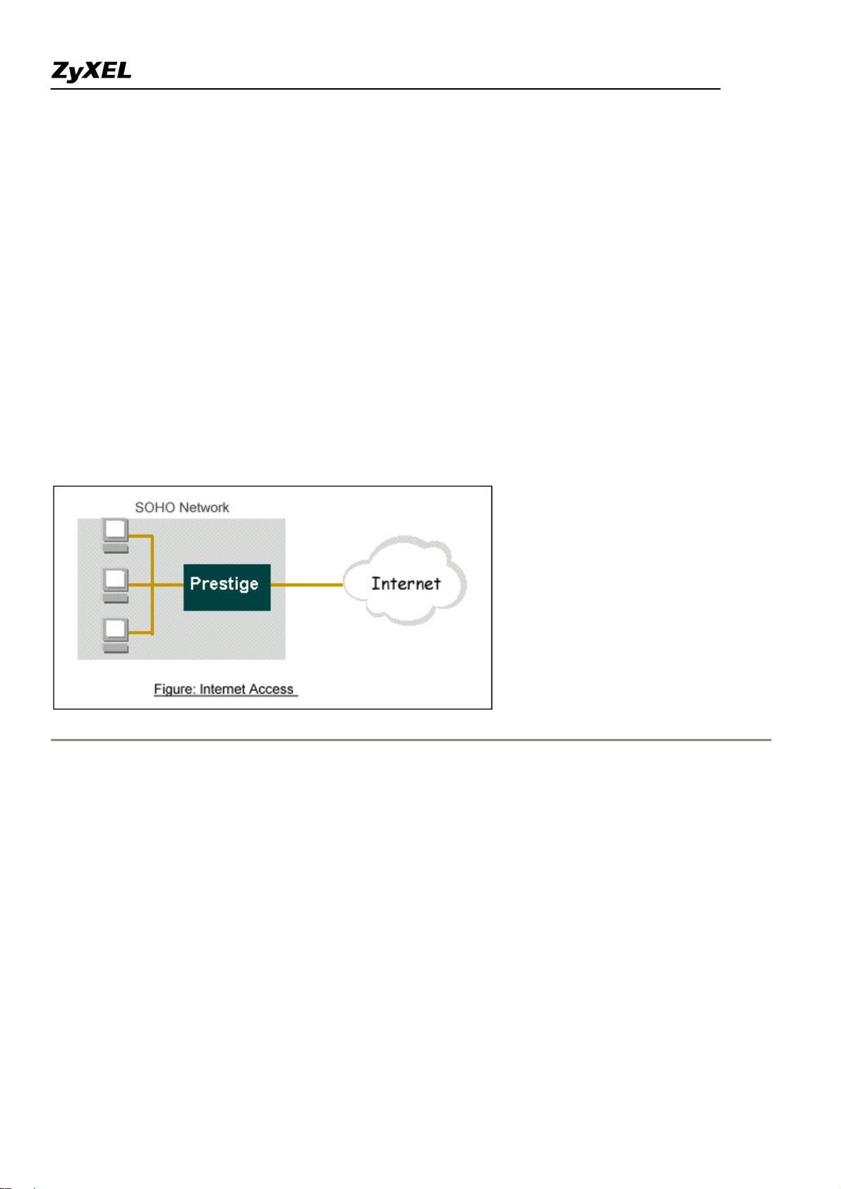
Internet Connection
A typical Internet access application of the Prestige is shown below. For a small office, there are some
components needs to be checked before accessing the Internet.
• Before you begin
• Setting up the Windows
• Setting up the Prestige router
• Troubleshooting
• Before you begin
The Prestige is shipped with the following factory default:
1. IP address = 192.168.1.1, subnet mask = 255.255.255.0 (24 bits)
2. DHCP server enabled with IP pool starting from 192.168.1.33
3. Default SMT menu password = 1234
• Setting up the PC (Windows OS)
1. Ethernet connection
All PCs must have an Ethernet adapter card installed.
All contents copyright (c) 2007 ZyXEL Communications Corporation.
9
Page 10

Prestige 2802HW(L)-Ix Support Notes
• If you only have one PC, connect the PC's Ethernet adapter to the Prestige's LAN port with a
crossover (red one) Ethernet cable.
• If you have more than one PC, both the PC's Ethernet adapters and the Prestige's LAN port must
be connected to an external hub with straight Ethernet cable.
2. TCP/IP Installation
You must first install TCP/IP software on each PC before you can use it for Internet access. If you have already
installed TCP/IP, go to the next section to configure it; otherwise, follow these steps to install:
• In the Control Panel/Network window, click Add button.
• In the Select Network Component Type windows, select Protocol and click Add.
• In the Select Network Protocol windows, select Microsoft from the manufacturers, then select
TCP/IP from the Network Protocols and click OK.
3. TCP/IP Configuration
Follow these steps to configure Windows TCP/IP:
• In the Control Panel/Network window, click the TCP/IP entry to select it and click Properties
button.
• In the TCP/IP Properties window, select obtain an IP address automatically.
Note: Do not assign arbitrary IP address and subnet mask to your PCs, otherwise, you will not be able to access
the Internet.
• Click the WINS configuration tab and select Disable WINS Resolution.
• Click the Gateway tab. Highlight any installed gateways and click the Remove button until there
are none listed.
• Click the DNS Configuration tab and select Disable DNS.
• Click OK to save and close the TCP/IP properties window
• Click OK to close the Network window. You will be prompted to insert your Windows CD or disk.
When the drivers are updated, you will be asked if you want to restart the PC. Make sure your
Prestige is powered on before answering Yes to the prompt. Repeat the above steps for each
Windows PC on your network.
• Setting up the Prestige router
All contents copyright (c) 2007 ZyXEL Communications Corporation.
10
Page 11
Prestige 2802HW(L)-Ix Support Notes
The following procedure is for the most typical usage of the Prestige where you have a single-user account
(SUA). The Prestige supports embedded web server that allows you to use Web browser to configure it. Before
configuring the router using Browser please be sure there is no Telnet or Console login.
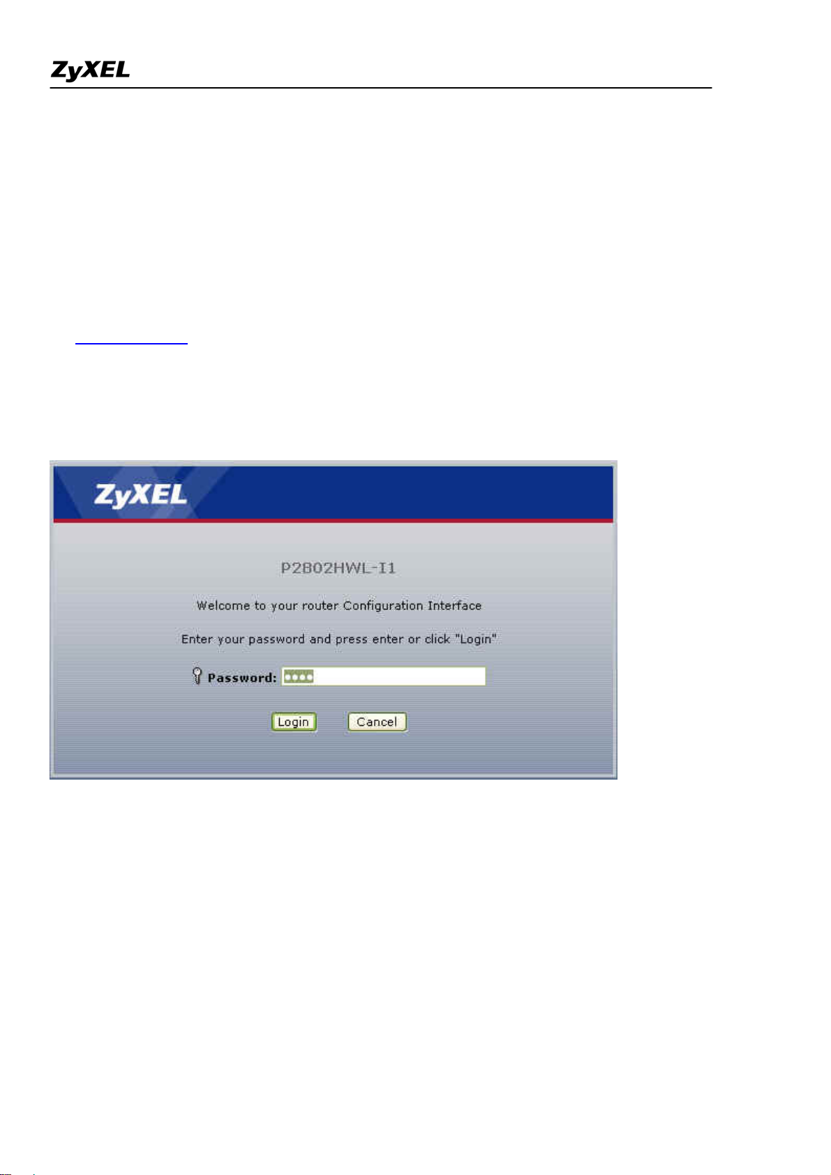
1. Retrieve Prestige Web
Please enter the LAN IP address of the Prestige router in the URL location to retrieve the web screen from the
Prestige. The default LAN IP of the Prestige is 192.168.1.1. See the example below. Note that you can either
use http://192.168.1.1
2. Login first
The default password is the default WEB GUI password, '1234'.
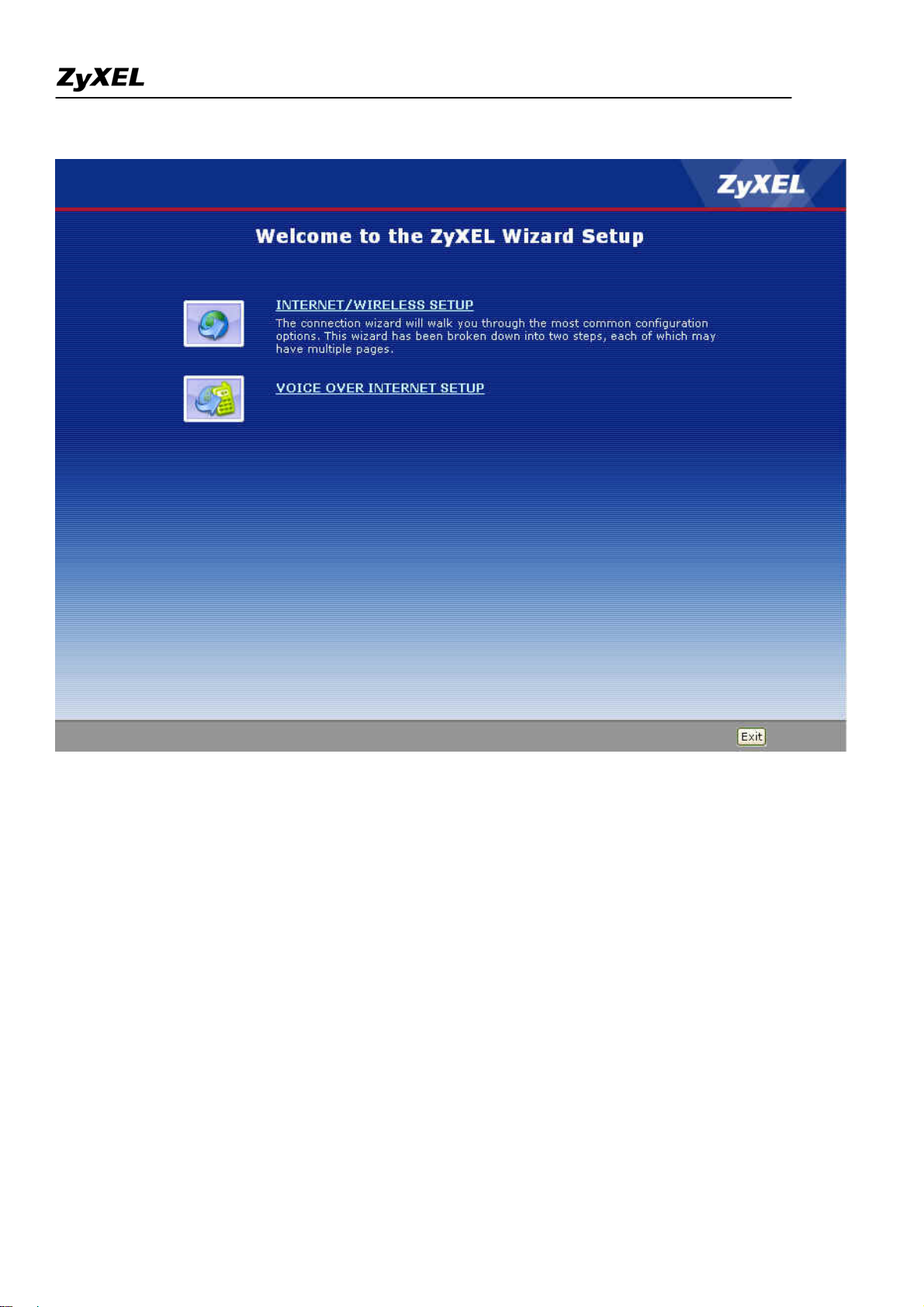
3. Configure Prestige for Internet access by using WIZARD SETUP
All contents copyright (c) 2007 ZyXEL Communications Corporation.
11
Page 12
Prestige 2802HW(L)-Ix Support Notes
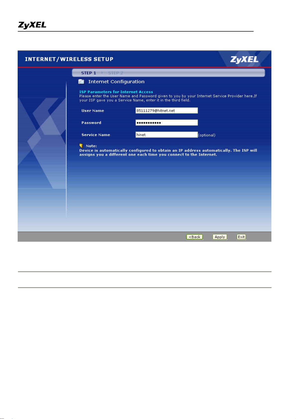
The Web screen shown below takes PPPoE as the example.
All contents copyright (c) 2007 ZyXEL Communications Corporation.
12
Page 13
Prestige 2802HW(L)-Ix Support Notes
Setup the Prestige as a DHCP Relay
• What is DHCP Relay?
DHCP stands for Dynamic Host Configuration Protocol. In addition to the DHCP server feature, the P2802
supports the DHCP relay function. When it is configured as DHCP server, it assigns the IP addresses to the
LAN clients. When it is configured as DHCP relay, it is reponsable for forwarding the requests and responses
negotiating between the DHCP clients and the server. See figure 1.
All contents copyright (c) 2007 ZyXEL Communications Corporation.
13
Page 14

Prestige 2802HW(L)-Ix Support Notes
• Setup the Prestige as a DHCP Client
1. Toggle the DHCP to Relay in Network>LAN>DHCP Setup and enter the IP address of the DHCP server in
the 'Remote DHCP Server' field.
14
All contents copyright (c) 2007 ZyXEL Communications Corporation.
Page 15
Prestige 2802HW(L)-Ix Support Notes
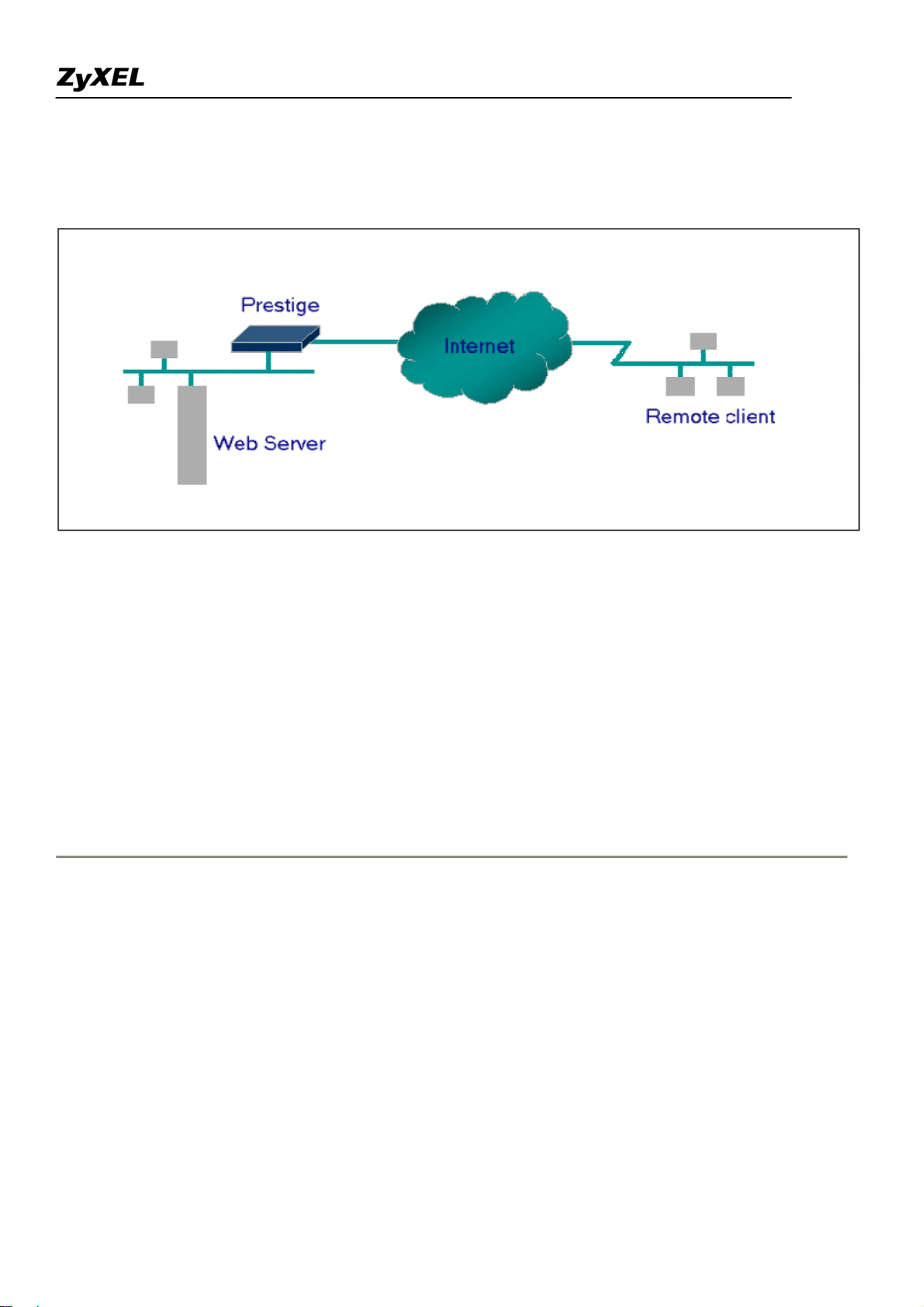
Configure an Internal Server Behind SUA
• Introduction
If you wish, you can make internal servers (e.g., Web, ftp or mail server) accessible for outside users, even
though SUA makes your LAN appear as a single machine to the outside world. A service is identified by the
port number. Also, since you need to specify the IP address of a server in the Prestige, a server must have a
fixed IP address and not be a DHCP client whose IP address potentially changes each time it is powered on.
In addition to the servers for specific services, SUA supports a default server. A service request that does not
have a server explicitly designated for it is forwarded to the default server. If the default server is not defined,
the service request is simply discarded.
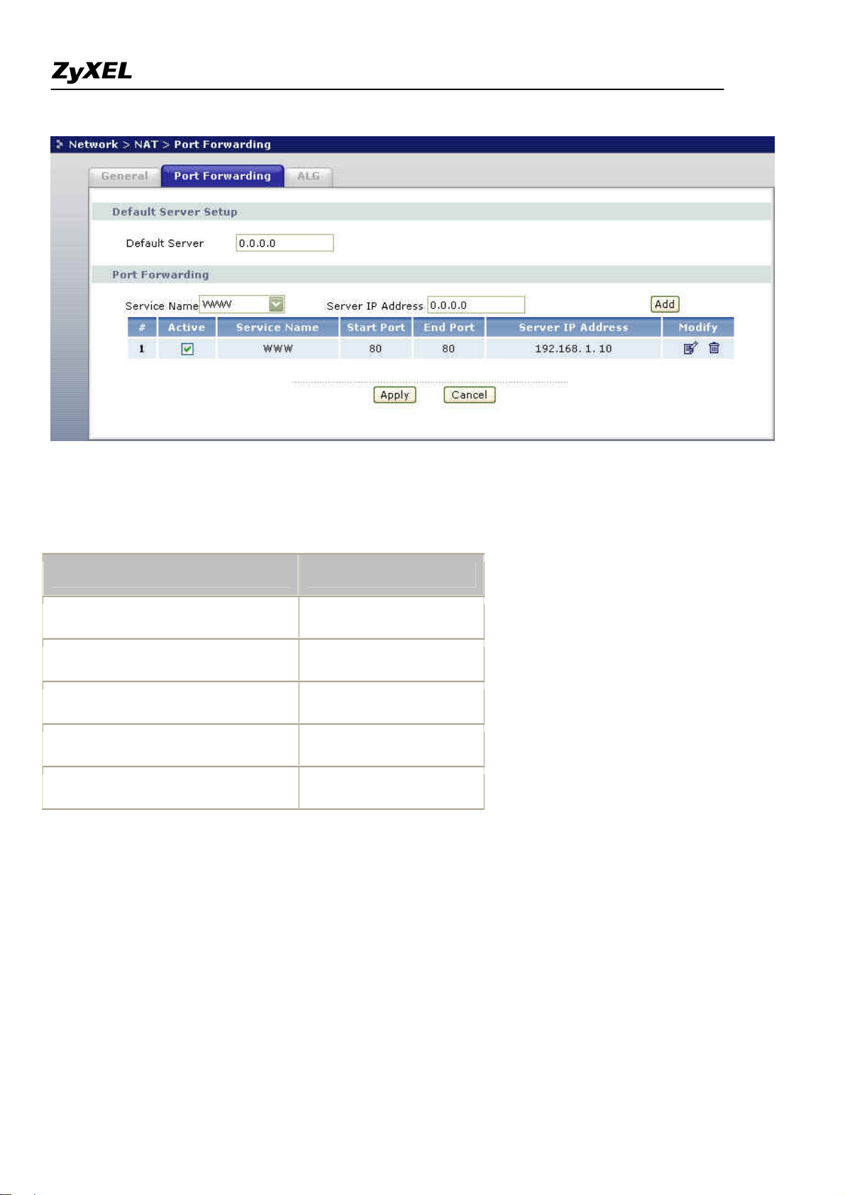
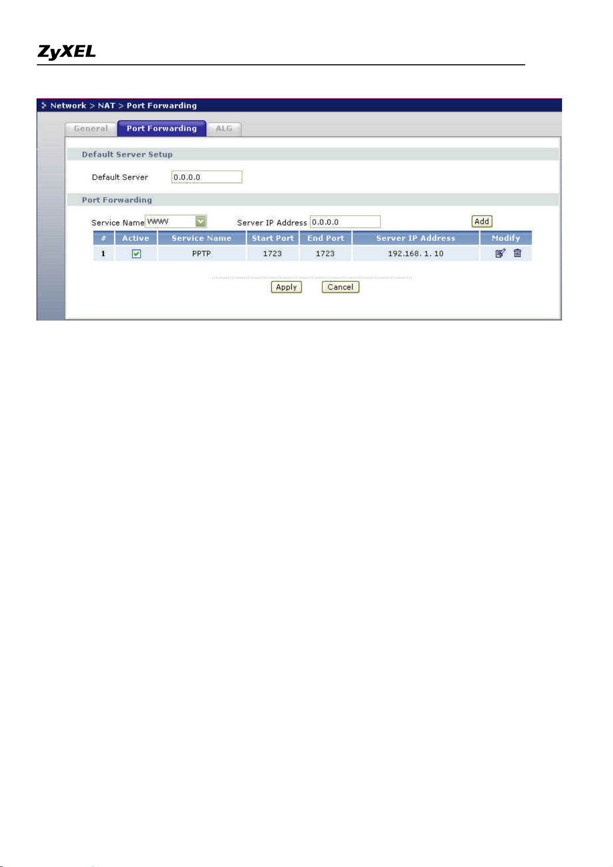
• Configuration
To make a server visible to the outside world, specify the port number of the service and the inside address of
the server in 'Network>NAT>Port Forwarding', Port Forwarding Configuration. The outside users can access
the local server using the Prestige's
WAN IP
address.
• For example (Configuring an internal Web server for outside access) :
All contents copyright (c) 2007 ZyXEL Communications Corporation.
15
Page 16
Prestige 2802HW(L)-Ix Support Notes
• Port numbers for some services
Service Port Number
FTP 21
Telnet 23
SMTP 25
DNS (Domain Name Server) 53
www-http (Web) 80
Configure a PPTP server Behind SUA
• Introduction
PPTP is a tunneling protocol defined by the PPTP forum that allows PPP packets to be encapsulated within
Internet Protocol (IP) packets and forwarded over any IP network, including the Internet itself.
In order to run the Windows 9x PPTP client, you must be able to establish an IP connection with a tunnel server
such as the Windows NT Server 4.0 Remote Access Server.
16
All contents copyright (c) 2007 ZyXEL Communications Corporation.
Page 17
Prestige 2802HW(L)-Ix Support Notes
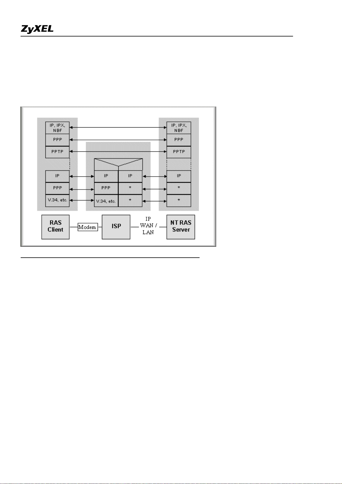
Windows Dial-Up Networking uses the Internet standard Point-to-Point (PPP) to provide a secure,optimized
multiple-protocol network connection over dial-up telephone lines. All data sent over this connection can be
encrypted and compressed, and multiple network level protocols (TCP/IP, NetBEUI and IPX) can be run
correctly. Windows NT Domain Login level security is preserved even across the Internet.
Window98 PPTP Client / Internet / NT RAS Server Protocol Stack
PPTP appears as new modem type (Virtual Private Networking Adapter) that can be selected when setting up a
connection in the Dial-Up Networking folder. The VPN Adapter type does not appear elsewhere in the system.
Since PPTP encapsulates its data stream in the PPP protocol, the VPN requires a second dial-up adapter. This
second dial-up adapter for VPN is added during the installation phase of the Upgrade in addition to the first
dial-up adapter that provides PPP support for the analog or ISDN modem.
The PPTP is supported in Windows NT and Windows 98 already. For Windows 95, it needs to be upgraded by
the Dial-Up Networking 1.2 upgrade.
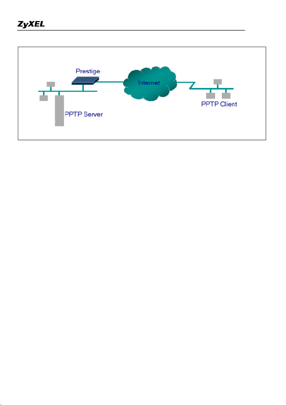
• Configuration
This application note explains how to establish a PPTP connection with a remote private network in the Prestige
SUA case. In ZyNOS, all PPTP packets can be forwarded to the internal PPTP Server (WinNT server) behind
SUA. The port number of the PPTP has to be Configure in the WEB GUI Network > NAT > Port
Forwarding
for Prestige to forward to the appropriate private IP address of Windows NT server.
All contents copyright (c) 2007 ZyXEL Communications Corporation.
17
Page 18
• Example
Prestige 2802HW(L)-Ix Support Notes
The following example shows how to dial to an ISP via the Prestige and then establish a tunnel to a private
network. There will be three items that you need to set up for PPTP application, these are PPTP server (WinNT),
PPTP client (Win9x) and the Prestige.
o PPTP server setup (WinNT)
Add the VPN service from Control Panel>Network
Add an user account for PPTP logged on user
Enable RAS port
Select the network protocols from RAS such as IPX, TCP/IP NetBEUI
Set the Internet gateway to Prestige
o PPTP client setup (Win9x)
Add one VPN connection from Dial-Up Networking by entering the correct
username & password and the IP address of the Prestige's Internet IP address for
logging to NT RAS server.
Set the Internet gateway to the router that is connecting to ISP
o Prestige router setup
• Before making a VPN connection from Win9x to WinNT server, you need to connect Prestige
router to your ISP first.
• Go to WEB GUI “Network>NAT>Port Forwarding”. Enter the IP address of the PPTP server
(WinNT server) and specify the Service Name for PPTP as shown below.
18
All contents copyright (c) 2007 ZyXEL Communications Corporation.
Page 19
Prestige 2802HW(L)-Ix Support Notes
When you have finished the above settings, you can ping to the remote Win9x client from
WinNT. This ping command is used to demonstrate that remote the Win9x can be reached across the
Internet. If the Internet connection between two LANs is achieve, you can place a VPN call from the
remote Win9x client.
For example:
C:\ping 203.66.113.2
When a dial-up connection to ISP is established, a default gateway is assigned to the router traffic
through that connection. Therefore, the output below shows the default gateway of the Win9x client
after the dial-up connection has been established.
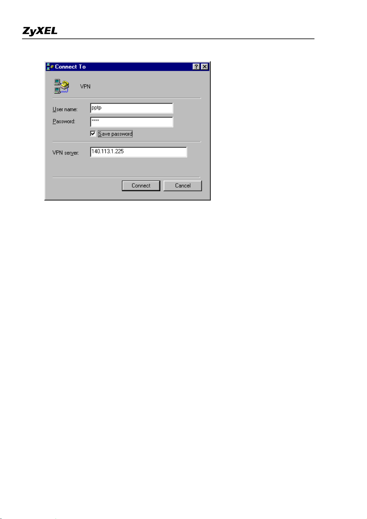
Before making a VPN connection from the Win9x client to the NT server, you need to know the exact
Internet IP address that the ISP assigns to Prestige router in SUA mode and enter this IP address in the
VPN dial-up dialog box. You can check this Internet IP address from PNC Monitor or WEB GUI Status
page. If the Internet IP address is a fixed IP address provided by ISP in SUA mode, then you can
always use this IP address for reaching the VPN server.
In the following example, the IP address '140.113.1.225' is dynamically assigned by ISP. You must
enter this IP address in the 'VPN Server' dialog box for reaching the PPTP server. After the VPN link is
established, you can start the network protocol application such as IP, IPX and NetBEUI.
19
All contents copyright (c) 2007 ZyXEL Communications Corporation.
Page 20
Prestige 2802HW(L)-Ix Support Notes
Using NAT / Multi-NAT
• What is Multi-NAT?
NAT (Network Address Translation-NAT RFC 1631) is the translation of an Internet Protocol address used
within one network to a different IP address known within another network. One network is designated the
inside
network and the other is the
outside
. Typically, a company maps its local inside network addresses to one
or more global outside IP addresses and "unmaps" the global IP addresses on incoming packets back into local
IP addresses. The IP addresses for the NAT can be either fixed or dynamically assigned by the ISP. In addition,
you can designate servers, e.g., a web server and a telnet server, on your local network and make them
accessible to the outside world. If you do not define any servers, NAT offers the additional benefit of firewall
protection. In such case, all incoming connections to your network will be filtered out by the Prestige, thus
preventing intruders from probing your network.
The SUA feature that the Prestige supports previously operates by mapping the private IP addresses to a global
IP address. It is only one subset of the NAT. The Prestige with ZyNOS V3.40 supports the most of the features
of the NAT based on RFC 1631, and we call this feature as 'Multi-NAT'. For more information on IP address
translation, please refer to RFC 1631,
• How NAT works
All contents copyright (c) 2007 ZyXEL Communications Corporation.
The IP Network Address Translator (NAT)
.
20
Page 21
Prestige 2802HW(L)-Ix Support Notes
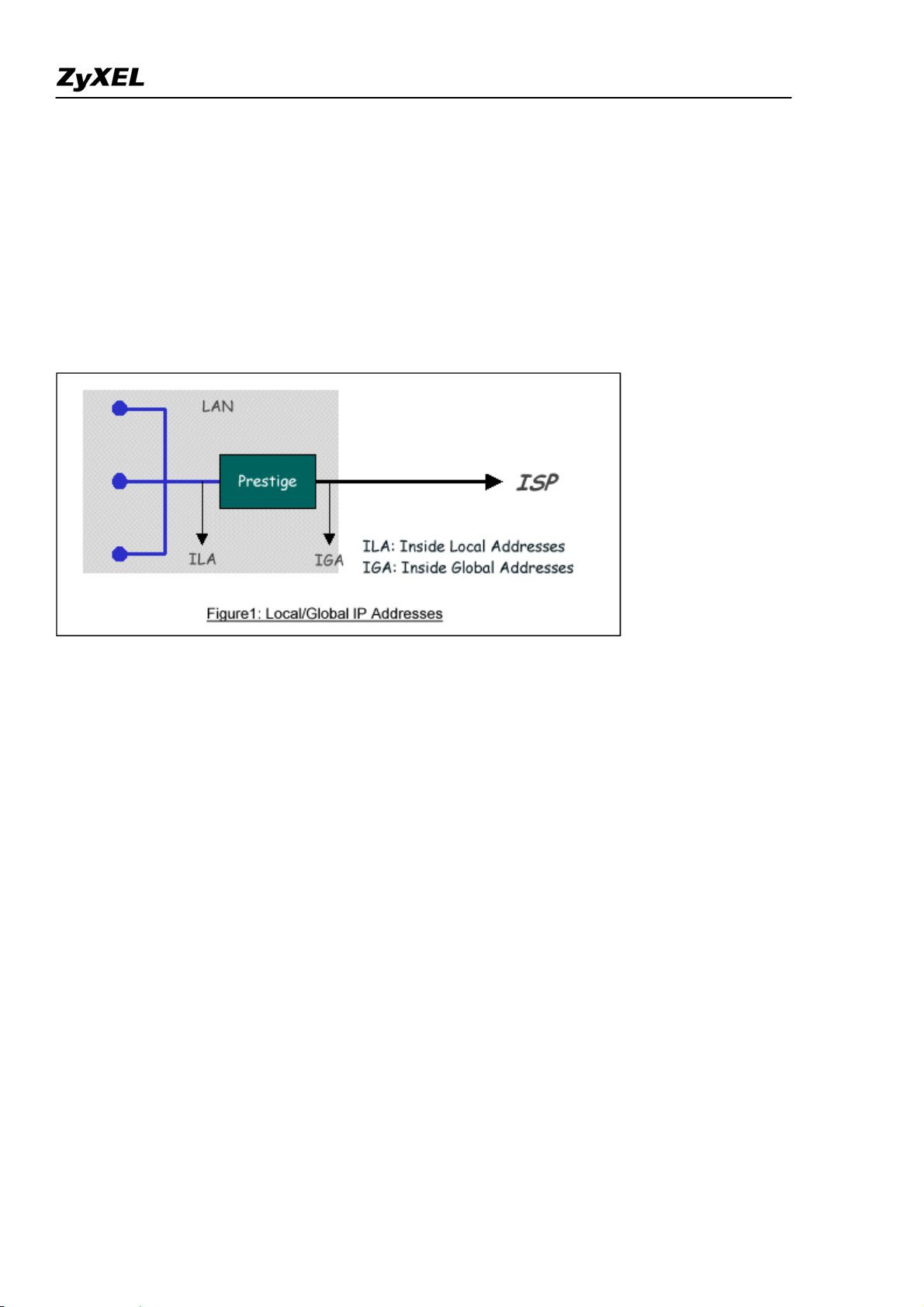
If we define the local IP addresses as the Internal Local Addresses (ILA) and the global IP addresses as the
Inside Global Address (IGA), see the following figure. The term 'inside' refers to the set of networks that are
subject to translation. NAT operates by mapping the ILA to the IGA required for communication with hosts on
other networks. It replaces the original IP source address (and TCP or UDP source port numbers) and then
forwards each packet to the Internet ISP, thus making them appear as if they had come from the NAT system
itself (e.g., the Prestige router). The Prestige keeps track of the original addresses and port numbers so incoming
reply packets can have their original values restored.
1. NAT Mapping Types
NAT supports five types of IP/port mapping. They are:
2. One to One
In One-to-One mode, the Prestige maps one ILA to one IGA.
3. Many to One
In Many-to-One mode, the Prestige maps multiple ILA to one IGA. This is equivalent to SUA (i.e., PAT, port
address translation), ZyXEL's Single User Account feature that previous ZyNOS routers supported (the SUA
only option in today's routers).
4. Many to Many Overload
In Many-to-Many Overload mode, the Prestige maps the multiple ILA to shared IGA.
All contents copyright (c) 2007 ZyXEL Communications Corporation.
21
Page 22

Prestige 2802HW(L)-Ix Support Notes
5. Many to Many No Overload
In Many-to-Many No Overload mode, the Prestige maps each ILA to unique IGA.
• Server
In Server mode, the Prestige maps multiple inside servers to one global IP address. This allows us to specify
multiple servers of different types behind the NAT for outside access. Note, if you want to map each server to
one unique IGA please use the One-to-One mode.
The following table summarizes these types.
NA T Type IP Mapping
Mapping
Direction
One-to-One ILA1<--->IGA1 Both
ILA1---->IGA1
Many-to-One (SUA/PAT)
ILA2---->IGA1
Outgoing
...
ILA1---->IGA1
ILA2---->IGA2
Many-to-Many Overload
ILA3---->IGA1
Outgoing
ILA4---->IGA2
...
ILA1---->IGA1
Many-to-Many No
Overload
(Allocate by Connections)
ILA2---->IGA3
ILA3---->IGA2
ILA4---->IGA4
Outgoing
...
Server
Incoming
Server 2 IP<----IGA1
Server 1 IP<----IGA1
• SUA Versus NAT
SUA (Single User Account) in previous ZyNOS versions is a NAT set with 2 rules, Many-to-One and Server.
The Prestige now has Full Feature NAT support to map global IP addresses to local IP addresses of clients or
servers. With multiple global IP addresses, multiple severs of the same type (e.g., FTP servers) are allowed on
the LAN for outside access. In previous ZyNOS versions (that supported SUA 'visible' servers had to be of
22
All contents copyright (c) 2007 ZyXEL Communications Corporation.
Page 23
Prestige 2802HW(L)-Ix Support Notes
different types. The Prestige supports NAT sets on a remote node basis. They are reusable, but only one set is
allowed for each remote node. The Prestige 2802HWL supports 8 sets since there are 8 remote node. The
default SUA (Read Only) Set is a convenient, pre-configured, read only, Many-to-One mapping set, sufficient
for most purposes and helpful to people already familiar with SUA in previous ZyNOS versions.
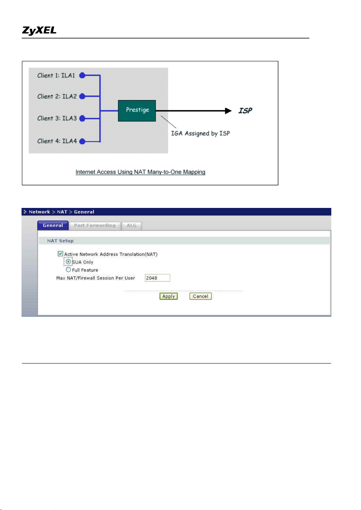
• WEB GUI Menus
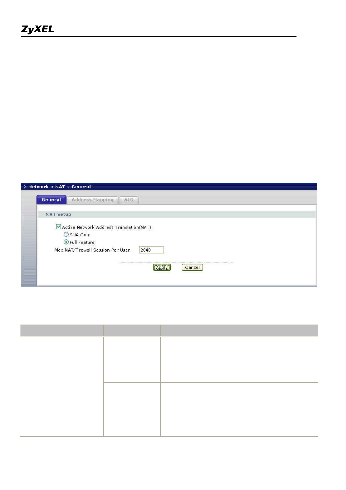
1. Applying NAT in the WEB GUI
You apply NAT via WEB GUI “Network>NAT>General" as displayed next. The next figure that you could
apply NAT for Internet access –Full Feature.
The following table describes the options for Network Address Translation.
Field Options Description
When you select this option the SMT will use Address
Full Feature
Mapping Set 1 (Menu 15.1-see later for further
discussion).
None
Network Address Translation
NAT is disabled when you select this option.
When you select this option the SMT will use Address
Mapping Set 255 (Menu 15.1-see later for further
SUA Only
discussion). This option use basically Many-to-One
Overload mapping. Select Full Feature when you
require other mapping types. It is a convenient,
All contents copyright (c) 2007 ZyXEL Communications Corporation.
23
Page 24
Prestige 2802HW(L)-Ix Support Notes
pre-configured, read only, Many-to-One mapping set,
sufficient for most purposes and helpful to people
already familiar with SUA in previous ZyNOS
versions. Note that there is also a Server type whose
IGA is 0.0.0.0 in this set.
2. Address Mapping Sets and NAT Server Sets
Use the Address Mapping Sets menus and submenus to create the mapping table used to assign global addresses
to LAN clients. Each remote node must specify which NAT Address Mapping Set to use. The P2802HWL has
8 remote nodes and so allows you to configure 8 NAT Address Mapping Set. You can see nine NAT Address
Mapping sets in WEB GUI Network > NAT > Address Mapping. You can only configure from Set 1 to
Set 10 when you select Full Feature in WEB GUI NAT configuration. When you select SUA Only, the Port
Forwarding
will auto configure as to Many to one and Server as default in system.
The NAT Server Set is a list of LAN side servers mapped to external ports. To use this set (one set for the
Prestige), a server rule must be set up inside the NAT Address Mapping set. Please see NAT Server Sets for
further information on these menus.
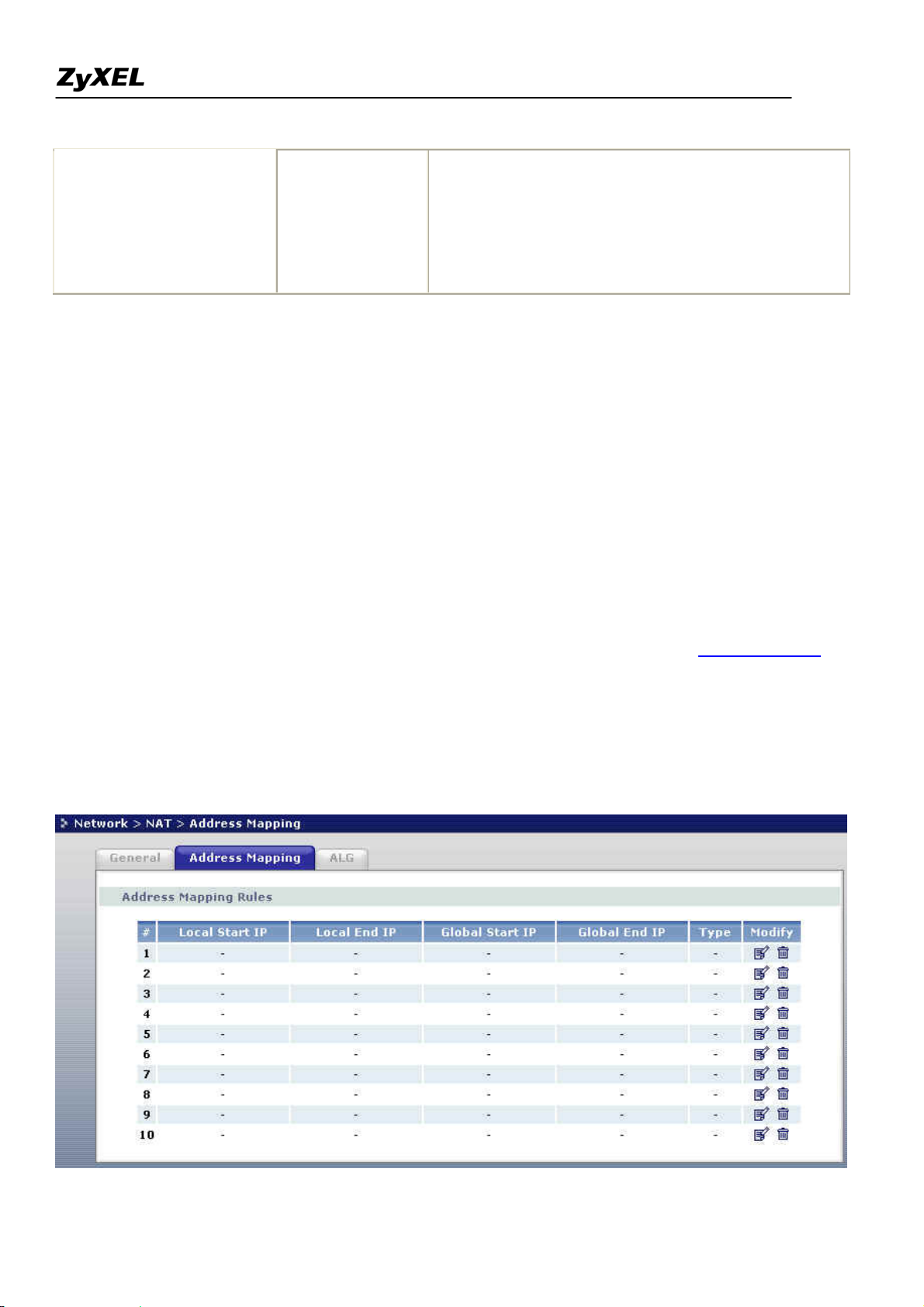
Enter WEB GUI Network > NAT > Address Mapping to bring up Address Mapping Sets Menu.
Now let's look at WEB GUI Menu Network > NAT > Address Mapping.
All contents copyright (c) 2007 ZyXEL Communications Corporation.
24
Page 25
Prestige 2802HW(L)-Ix Support Notes
Field Description Option/Example
# This is the rule index number.
Local Start IP This is the starting local IP address (ILA).
0.0.0.0 for the
Many-to-One type.
This is the starting local IP address (ILA). If the rule is for all
Local End IP
local IPs, then the Start IP is 0.0.0.0 and the End IP is
255.255.255.255
255.255.255.255.
Global Start
This is the starting global IP address (IGA). If you have a
0.0.0.0
IP
dynamic IP, enter 0.0.0.0 as the Global Start IP.
Global End IP This is the ending global IP address (IGA). N/A
Type This is the NAT mapping types. Many-to-One and Server
Click the edit icon to go to the screen where you can edit the
address mapping rule.
Modify
Click the delete icon to delete an existing address mapping
N/A
rule. Note that subsequent address mapping rules move up by
one when you take this action.
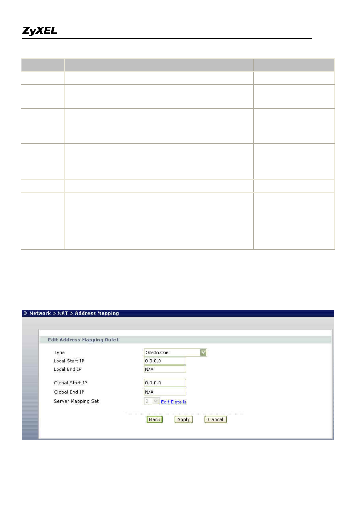
To edit an address mapping rule, click the rule's edit icon in the Address Mapping screen to display the screen
show next.
All contents copyright (c) 2007 ZyXEL Communications Corporation.
25
Page 26
Prestige 2802HW(L)-Ix Support Notes
The following table describes the fields in this screen.
Field Description Option/Example
One-to-One
Press [CHOOSE BAR] to toggle through a total of 5 types.
Many-to-One
Many-to-Many Overload
Type
These are the mapping types discussed above plus a server type.
Many-to-Many No
Some examples follow to clarify these a little more.
Overload
Server
Start This is the starting local IP address (ILA) 0.0.0.0
Local
IP
End
This is the ending local IP address (ILA). If the rule is for all
local IPs, then put the Start IP as 0.0.0.0 and the End IP as
255.255.255.255
255.255.255.255. This field is N/A for One-to-One type.
This is the starting global IP address (IGA). If you have a
Global
IP
Start
dynamic IP, enter 0.0.0.0 as the Global Start IP.
This is the ending global IP address (IGA). This field is N/A for
End
0.0.0.0
200.1.1.64
One-to-One, Many-to-One and Server types.
Note: For all Local and Global IPs, the End IP address must begin after the IP Start address, i.e., you cannot
have an End IP address beginning before the Start IP address.
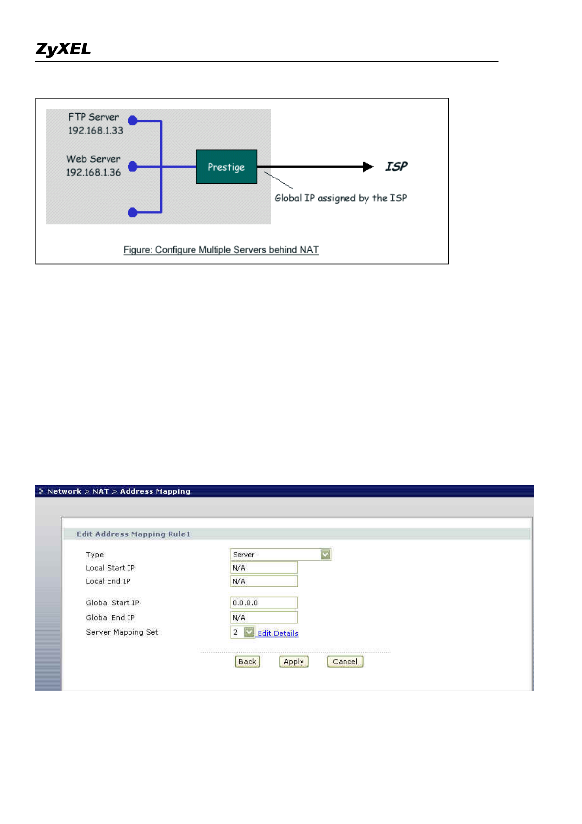
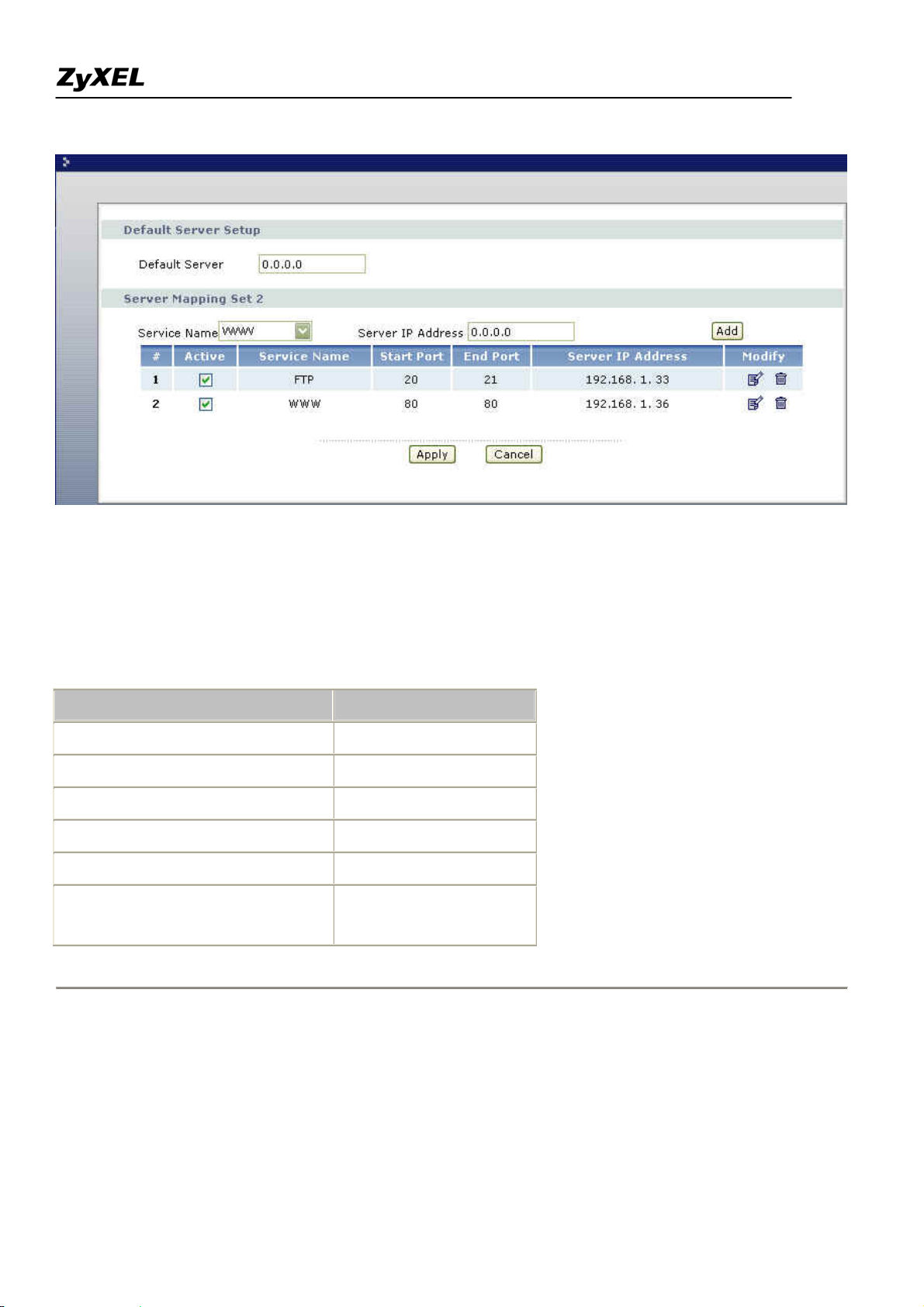
• NAT Server Sets
The NAT Server Set is a list of LAN side servers mapped to external ports (similar to the old SUA menu of
before). If you wish, you can make inside servers for different services, e.g., Web or FTP, visible to the outside
users, even though NAT makes your network appears as a single machine to the outside world. A server is
identified by the port number, e.g., Web service is on port 80 and FTP on port 21.
As an example (see the following figure), if you have a Web server at 192.168.1.36 and a FTP server at
192.168.1.33, then you need to specify for port 80 (Web) the server at IP address 192.168.1.36 and for port 21
(FTP) another at IP address 192.168.1.33.
26
All contents copyright (c) 2007 ZyXEL Communications Corporation.
Page 27
Prestige 2802HW(L)-Ix Support Notes
Please note that a server can support more than one service, e.g., a server can provide both FTP and Mail
service, while another provides only Web service.
The following procedures show how to configure a server behind NAT.
Step 1. Enter Network > NAT > Address Mapping in the WEB GUI to go to Address Mapping Setup.
Step 2. Enter Edit Details of Server Mapping Set to go to NAT Server Setup.
Step 3. Selet the service type in Service Name field and the inside IP address of the server in the Server IP
Address field.
Step 4. Press Add icon to add your configuration after you define all the servers, press Apply icon to save the
settings.
27
All contents copyright (c) 2007 ZyXEL Communications Corporation.
Page 28
Prestige 2802HW(L)-Ix Support Notes
The most often used port numbers are shown in the following table. Please refer RFC 1700 for further
information about port numbers.
Service Port Number
FTP 20,21
Telnet 23
SMTP 25
DNS (Domain Name Server) 53
www-http (Web) 80
PPTP (Point-to-Point Tunneling
1723
Protocol)
1. Internet Access Only
In our Internet Access example, we only need one rule where all our ILAs map to one IGA assigned by the ISP.
See the following figure.
28
All contents copyright (c) 2007 ZyXEL Communications Corporation.
Page 29
Prestige 2802HW(L)-Ix Support Notes
From WEB GUI Network > NAT > General shown above simply choose the SUA Only option in the NAT
Setup. This is the Many-to-One mapping discussed earlier.
2. Internet Access with an Internal Server
29
All contents copyright (c) 2007 ZyXEL Communications Corporation.
Page 30
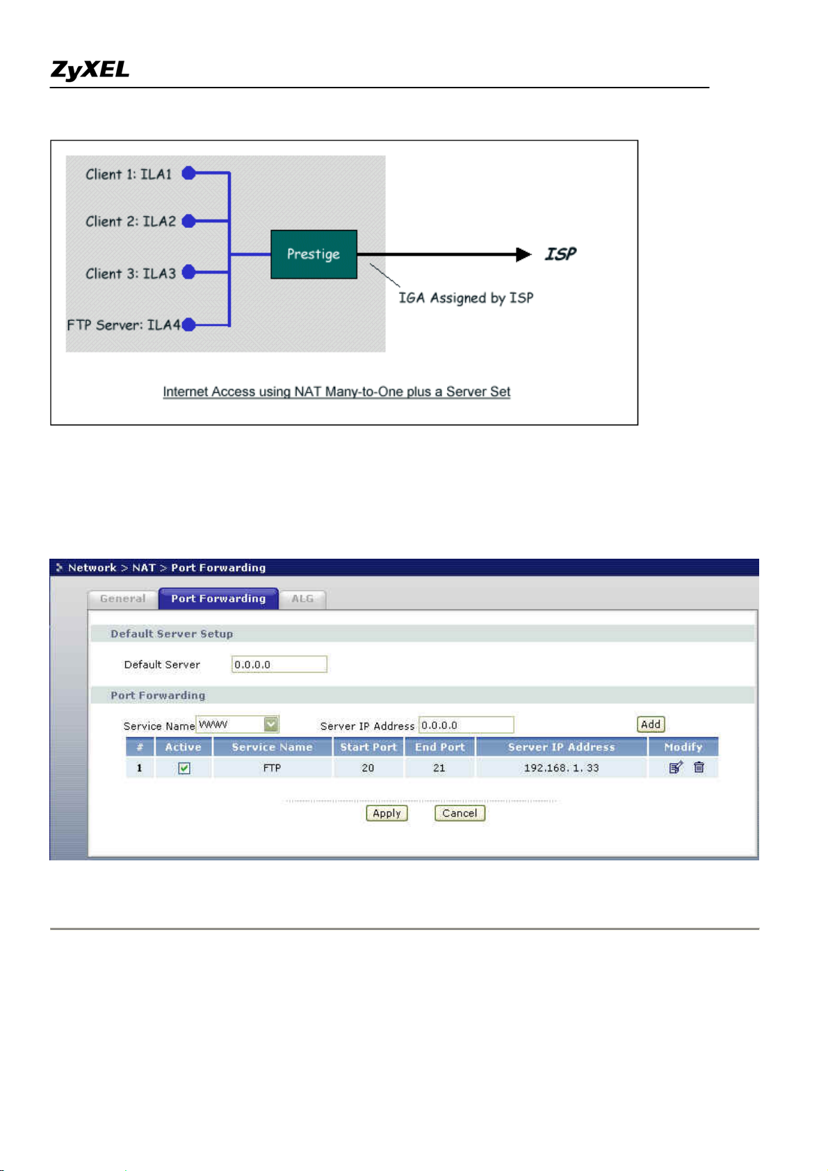
Prestige 2802HW(L)-Ix Support Notes
In this case, we do exactly as above (use the convenient pre-configured SUA Only set) and also go to Menu
Network > NAT > Port Forwarding
as shown below.
to specify the Internet Server behind the NAT as shown in the NAT
3. Using Multiple Global IP addresses for clients and servers (One-to-One, Many-to-One, Server Set mapping
types are used)
30
All contents copyright (c) 2007 ZyXEL Communications Corporation.
Page 31

Prestige 2802HW(L)-Ix Support Notes
In this case we have 3 IGAs (IGA1, IGA2 and IGA3) from the ISP. We have two very busy internal FTP
servers and also an internal general server for the web and mail. In this case, we want to assign the 3 IGAs by
the following way using 4 NAT rules.
5. Rule 1 (One-to-One type) to map the FTP Server 1 with ILA1 (192.168.1.10) to IGA1.
6. Rule 2 (One-to-One type) to map the FTP Server 2 with ILA2 (192.168.1.11) to IGA2.
7. Rule 3 (Many-to-One type) to map the other clients to IGA3.
8. Rule 4 (Server type) to map a web server and mail server with ILA3 (192.168.1.20) to IGA3. Type
Server allows us to specify multiple servers, of different types, to other machines behind NAT on
the LAN.
Step 1:
In this case, we need to configure Address Mapping Set 1 from Network > NAT > Address Mapping
Menu. Therefore we must choose the Full Feature option in Network > NAT > General.
All contents copyright (c) 2007 ZyXEL Communications Corporation.
31
Page 32

Prestige 2802HW(L)-Ix Support Notes
Step 2:
Go to menu 15.1 and choose 1 (not 255, SUA this time) to begin configuring this new set. Enter a Set Name,
choose the Edit Action and then select 1 from Select Rule field. Press [ENTER] to confirm. See the following
setup for the four rules in our case.
Rule 1 Setup: Select One-to-One type to map the FTP Server 1 with ILA1 (192.168.1.10) to IGA1.
Rule 2 Setup: Selecting One-to-One type to map the FTP Server 2 with ILA2 (192.168.1.11) to IGA2.
All contents copyright (c) 2007 ZyXEL Communications Corporation.
32
Page 33

Prestige 2802HW(L)-Ix Support Notes
Rule 3 Setup: Select Many-to-One type to map the other clients to IGA3.
Rule 4 Setup: Select Server type to map our web server and mail server with ILA3 (192.168.1.20) to IGA3.
All contents copyright (c) 2007 ZyXEL Communications Corporation.
33
Page 34

Prestige 2802HW(L)-Ix Support Notes
When we have configured all four rules WEB GUI Address Mapping Configuration should look as follows.
Idx Local Start IP Local End IP Global Start IP Global End IP Type
--- --------------- --------------- --------------- --------------- ------
1. 192.168.1.10 [IGA1] 1-1
2. 192.168.1.11 [IGA2] 1-1
3. 0.0.0.0 255.255.255.255 [IGA3] M-1
4. [IGA3] Server
5.
6.
7.
8.
9.
10.
Step 3:
Now we configure all other incoming traffic to go to our web server aand mail server from Menu 15.2 - NAT
Server Setup (not Set 1, Set 1 is used for SUA Only case).
34
All contents copyright (c) 2007 ZyXEL Communications Corporation.
Page 35

Prestige 2802HW(L)-Ix Support Notes
4. Support Non NAT Friendly Applications
Some servers providing Internet applications such as some mIRC servers do not allow users to login using the
same IP address. In this case it is better to use Many-to-Many No Overload or One-to-One NAT mapping types,
thus each user login to the server using a unique global IP address. The following figure illustrates this.
One rule configured for using Many-to-Many No Overload mapping type is shown below.
All contents copyright (c) 2007 ZyXEL Communications Corporation.
35
Page 36

Prestige 2802HW(L)-Ix Support Notes
The three rules configured for using One-to-One mapping type is shown below.
All contents copyright (c) 2007 ZyXEL Communications Corporation.
36
Page 37

Prestige 2802HW(L)-Ix Support Notes
Prestige supports multiple type of NAT mapping rules
All contents copyright (c) 2007 ZyXEL Communications Corporation.
37
Page 38

Prestige 2802HW(L)-Ix Support Notes
• SUA
• One to One
• Many to One
• Many to Many overload
• Many One to One
• Server
The following table summarizes these types.
NAT Type IP Mapping
One-to-One ILA1<--->IGA1
ILA1<--->IGA1
Many-to-One
ILA2<--->IGA1
(SUA/PAT)
...
ILA1<--->IGA1
ILA2<--->IGA2
Many-to-Many
ILA3<--->IGA1
Overload
ILA4<--->IGA2
ILA1<--->IGA1
ILA2<--->IGA2
Many-to-Many No
ILA3<--->IGA3
Overload
ILA4<--->IGA4
Server
(SUA)
...
Server 1 IP<--->IGA1
Server 2 IP<--->IGA1
All contents copyright (c) 2007 ZyXEL Communications Corporation.
38
Page 39

Prestige 2802HW(L)-Ix Support Notes
Using the Dynamic DNS (DDNS)
1. What is DDNS?
The DDNS service, an IP Registry provides a public central database where information such as email
addresses, hostnames, IPs etc. can be stored and retrieved. This solves the problems if your DNS server uses an
IP associated with dynamic IPs.
Without DDNS, we always tell the users to use the WAN IP of the Prestige to access the internal server. It is
inconvenient for the users if this IP is dynamic. With DDNS supported by the Prestige, you apply a DNS name
(e.g., www.zyxel.com.tw) for your server (e.g., Web server) from a DDNS server. The outside users can always
access the web server using the www.zyxel.com.tw regardless of the WAN IP of the Prestige.
When the ISP assigns the Prestige a new IP, the Prestige must inform the DDNS server the change of this IP so
that the server can update its IP-to-DNS entry. Once the IP-to-DNS table in the DDNS server is updated, the
DNS name for your web server (i.e., www.zyxel.com.tw) is still usable.
The DDNS server stores password-protected email addresses with IPs and hostnames and accepts queries based
on email addresses. So, there must be an email entry in the Prestige menu 1.
The DDNS servers the Prestige supports currently is WWW.DYNDNS.ORG where you apply the DNS from
and update the WAN IP to.
• Setup the DDNS
• Before configuring the DDNS settings in the Prestige, you must register an account from the
DDNS server such as WWW.DYNDNS.ORG first. After the registration, you have a hostname for
your internal server and a password using to update the IP to the DDNS server.
• Go to Advanced > Dynamic DNS in WEB GUI and active 'Dynamic DNS' checkbox and press
Apply for configuring the settings of the DDNS.
All contents copyright (c) 2007 ZyXEL Communications Corporation.
39
Page 40

Prestige 2802HW(L)-Ix Support Notes
Key Settings for using DDNS function:
Option Description
Active Dynamic DNS
Select this check box to use dynamic DNS
Enter the DDNS server in this field. Currently, we support
Service Provider
WWW.DYNDNS.ORG
Select the type of service that you are registered for from your Dynamic DNS
Dynamic DNS Type
service provider.
Enter the hostname you subscribe from the above DDNS server.
Host Name
You can specify up to two host names in the field separated by a comma (“,”)
User Name
Password
Enter the user name.
Enter the password that the DDNS server gives to you.
.
Enable Wildcard
Select the check box to enable DynDNS Wildcard.
Option
This option is available when CustomDNS is selected in the DDNS Type field.
Enable off line option
Check with your Dynamic DNS service provider to have traffic redirected to a
All contents copyright (c) 2007 ZyXEL Communications Corporation.
40
Page 41

Prestige 2802HW(L)-Ix Support Notes
RL (that you can specify) while you are off line.
Use WAN IP Addr ess
Select this option to update IP Address of the host name to the WAN IP Address.
Select this option only when there are one or more NAT routers between ZyXEL
Device and DDNS server. This feature has DDNS server automatically detect
Dynamic DNS server
auto detect IP Address
and use the IP address of the NAT router that has a public IP address.
NOTES :
The DDNS server may not be able to detect the proper IP address if there is an
HTTP proxy server between the ZyXEL Device and the DDNS server.
Use specific IP Address
Tyep the IP address of hostname. Use this if you have a static IP address.
Network Management Using SNMP
1. SNMP Overview
The
Simple Network Management Protocol
(SNMP) is an applications-layer protocol used to exchange the
management information between network devices (e.g., routers). By using SNMP, network administrators can
more easily manage network performance, find and solve network problems. The SNMP is a member of the
TCP/IP protocol suite, it uses the UDP to exchange messages between a management Client and an Agent,
residing in a network node.
There are two versions of SNMP: Version 1 and Version 2. ZyXEL supports SNMPv1. Most of the changes
introduced in Version 2 increase SNMP's security capabilities. SNMP encompasses three main areas:
1. A small set of management operations.
2. Definitions of management variables.
3. Data representation.
The operations allowed are: Get, GetNext, Set, and Trap. These functions operates on variables that exist in
network nodes. Examples of variables include statistic counters, node port status, and so on. All of the SNMP
management functions are carried out through these simple operations. No action operations are available, but
these can be simulated by the setting of flag variables. For example, to reset a node, a counter variable named
'time to reset' could be set to a value, causing the node to reset after the time had elapsed.
SNMP variables are defined using the OSI Abstract Syntax Notation One (ASN.1). ASN.1 specifies how a
variable is encoded in a transmitted data frame; it is very powerful because the encoded data is self-defining.
41
All contents copyright (c) 2007 ZyXEL Communications Corporation.
Page 42

Prestige 2802HW(L)-Ix Support Notes
For example, the encoding of a text string includes an indication that the data unit is a string, along with its
length and value. ASN.1 is a flexible way of defining protocols, especially for network management protocols
where nodes may support different sets of manageable variables.
The net of variables that each node supports is called the
Management Information Base
(MIB). The MIB is
made up of several parts, including the Standard MIB, specified as part of SNMP, and Enterprise Specific MIB,
which are defined by different manufacturer for hardware specific management.
The current Internet-standard MIB, MIB-II, is defined in RFC 1213 and contains 171 objects. These objects are
grouped by protocol (including TCP, IP, UDP, SNMP, and other categories, including 'system' and 'interface.'
The Internet Management Model is as shown in figure 1. Interactions between the NMS and managed devices
can be any of four different types of commands:
6. Reads
Read is used to monitor the managed devices, NMSs read variables that are maintained by the devices.
7. Writes
Write is used to control the managed devices, NMSs write variables that are stored in the managed
devices.
8. Traversal operations
NMSs use these operations to determine which variables a managed device supports and to sequentially
gather information from variable tables (such as IP routing table) in managed devices.
9. Traps
The managed devices to asynchronously report certain events to NMSs use trap.
All contents copyright (c) 2007 ZyXEL Communications Corporation.
42
Page 43

Prestige 2802HW(L)-Ix Support Notes
2. SNMPv1 Operations
SNMP itself is a simple request/response protocol. 4 SNMPv1 operations are defined as below.
• Get
Allows the NMS to retrieve an object variable from the agent.
• GetNext
Allows the NMS to retrieve the next object variable from a table or list within an agent. In
SNMPv1, when a NMS wants to retrieve all elements of a table from an agent, it initiates a Get
operation, followed by a series of GetNext operations.
• Set
Allows the NMS to set values for object variables within an agent.
• Trap
Used by the agent to inform the NMS of some events.
The SNMPv1 messages contains two part. The first part contains a version and a community name. The second
part contains the actual SNMP protocol data unit (PDU) specifying the operation to be performed (Get, Set, and
43
All contents copyright (c) 2007 ZyXEL Communications Corporation.
Page 44

Prestige 2802HW(L)-Ix Support Notes
so on) and the object values involved in the operation. The following figure shows the SNMPv1 message
format.
The SNMP PDU contains the following fields:
• PDU type Specifies the type of PDU.
• Request ID Associates requests with responses.
• Error status Indicates an error and an error type.
• Error index Associates the error with a particular object variable.
• Variable-bindings Associates particular object with their value.
3. ZyXEL SNMP Implementation
ZyXEL currently includes SNMP support in some Prestige routers. It is implemented based on the SNMPv1, so
it will be able to communicate with SNMPv1 NMSs. For SNMPv1 operation, ZyXEL permits one community
string so that the router can belong to only one community and allows trap messages to be sent to only one
NMS manager.
Some traps are sent to the SNMP manager when anyone of the following events happens:
• coldStart (defined in RFC-1215) :
If the machine coldstarts, the trap will be sent after booting.
All contents copyright (c) 2007 ZyXEL Communications Corporation.
44
Page 45

Prestige 2802HW(L)-Ix Support Notes
• warmStart (defined in RFC-1215) :
If the machine warmstarts, the trap will be sent after booting.
• linkDown (defined in RFC-1215) :
If any link of IDSL or WAN is down, the trap will be sent with the port number . The port number is its
interface index under the interface group.
• linkUp (defined in RFC-1215) :
If any link of IDSL or WAN is up, the trap will be sent with the port number . The port number is its
interface index under the interface group.
• authenticationFailure (defined in RFC-1215) :
When receiving any SNMP get or set requirement with wrong community, this trap is sent to the manager.
1. whyReboot (defined in ZYXEL-MIB) :
When the system is going to restart (warmstart), the trap will be sent with the reason of restart before rebooting.
(i) For intentional reboot :
In some cases (download new files, CI command "sys reboot", ...), reboot is done intentionally. And traps with
the message "System reboot by user !" will be sent.
(ii) For fatal error :
System has to reboot for some fatal errors. And traps with the message of the fatal code will be sent.
All contents copyright (c) 2007 ZyXEL Communications Corporation.
45
Page 46

Prestige 2802HW(L)-Ix Support Notes
4. Configure the Prestige for SNMP
The SNMP related settings in Prestige are configured in WEB GUI menu
SNMP
, SNMP Configuration. The following steps describe a simple setup procedure for configuring all SNMP
settings.
Advanced > Remote MGMT >
All contents copyright (c) 2007 ZyXEL Communications Corporation.
46
Page 47

Prestige 2802HW(L)-Ix Support Notes
Key Settings:
Option Descriptions
You may change the server port number for a server if needed, however you must use
Port
the same port number in order to use that service for remote management.
Select the interface through which a computer may access the ZyXEL Device using
Access Status
the service.
A secured client is a “trusted” computer that is allowed to communicate with the
ZyXEL device using this service.
Secured Client
Select All to allow any computer to access ZyXEL device using this service.
IP
Choose Selected to just allow the computer with the IP address that you specify to
access the ZyXEL device using this service.
Enter the correct Get Community. This Get Community must match the 'Get-' and
Get Community
'GetNext' community requested from the NMS. The default is 'public'.
Set Community
Community
Enter the correct Set Community. This Set Community must match the
'Set-community requested from the NMS. The default is 'public'.
Enter the community name in each sent trap to the NMS. This Trap Community must
match what the NMS is expecting. The default is 'public'.
47
All contents copyright (c) 2007 ZyXEL Communications Corporation.
Page 48

Prestige 2802HW(L)-Ix Support Notes
Destination
Using syslog
4. Prestige Setup
Enter the IP address of the NMS that you wish to send the traps to. If 0.0.0.0 is
entered, the Prestige will not send trap any NMS manager.
Configuration:
1. Click Active to enable Syslog logging.
2. Syslog IP Address, enter the IP address of the UNIX server that you wish to send the syslog.
3. Log Facility, select the location from the drop down list box. The log facility allows you to log the messages
to different files in the syslog server. Refer to the syslog server manual for more information.
• UNIX Setup
48
All contents copyright (c) 2007 ZyXEL Communications Corporation.
Page 49

Prestige 2802HW(L)-Ix Support Notes
1. Make sure that your syslogd starts with -r argument.
-r
, this option will enable the facility to receive message from the network using an Internet domain socket with
the syslog services. The default setting is not enabled.
2. Edit the file /etc/syslog.conf by adding the following line at the end of the /etc/syslog.conf file.
local1.* /var/log/zyxel.log
Where /var/log/zyxel.log is the full path of the log file.
3. Restart syslogd.
• CDR log(call messages)
Format:
sdcmdSyslogSend( SYSLOG_CDR, SYSLOG_INFO, String );
String = board xx line xx channel xx, call xx, str
board = the hardware board ID
line = the WAN ID in a board
channel = channel ID within the WAN
call = the call reference number which starts from 1 and increments by 1 for each new call
str = C01 Outgoing Call dev xx ch xx (dev:device No. ch:channel No.)
C01 Incoming Call xxxxBps xxxxx (L2TP,xxxxx means Remote Call ID)
C01 Incoming Call xxxx (means connected speed) xxxxx (means Remote Call ID)
L02 Tunnel Connected(L2TP)
C02 OutCall Connected xxxx (means connected speed) xxxxx (means Remote Call ID)
C02 CLID call refused
L02 Call Terminated
C02 Call Terminated
Example:
Feb 14 16:57:17 192.168.1.1 ZyXEL Communications Corp.: board 0 line 0 channel 0, call 18, C01 Incoming
Call OK
Feb 14 17:07:18 192.168.1.1 ZyXEL Communications Corp.: board 0 line 0 channel 0, call 18, C02 Call Terminated
49
All contents copyright (c) 2007 ZyXEL Communications Corporation.
Page 50

Prestige 2802HW(L)-Ix Support Notes
• Packet triggered log
Format:
sdcmdSyslogSend( SYSLOG_PKTTRI, SYSLOG_NOTICE, String );
String = Packet trigger: Protocol=xx Data=xxxxxxxxxx
Protocol: (1:IP 2:IPX 3:IPXHC 4:BPDU 5:ATALK 6:IPNG)
Data: We will send forty-eight Hex characters to the server
Example:
Jul 19 11:28:39 192.168.102.2 ZyXEL Communications Corp.: Packet Trigger: Protocol=1,
Data=4500003c100100001f010004c0a86614ca849a7b08004a5c020001006162636465666768696a6b6c6d6e6f7071727374
Jul 19 11:28:56 192.168.102.2 ZyXEL Communications Corp.: Packet Trigger: Protocol=1,
Data=4500002c1b0140001f06b50ec0a86614ca849a7b0427001700195b3e00000000600220008cd40000020405b4
• Filter log
This message is available when the 'Log' is enabled in the filter rule setting. The message consists of the packet
header and the log of the filter rules.
Format:
sdcmdSyslogSend(SYSLOG_FILLOG, SYSLOG_NOTICE, String );
String = IP[Src=xx.xx.xx.xx Dst=xx.xx.xx.xx prot spo=xxxx dpo=xxxx]S04>R01mD
IP[...] is the packet header and S04>R01mD means filter set 4 (S) and rule 1 (R), match (m) drop (D).
Src: Source Address
Dst: Destination Address
prot: Protocol (TCP,UDP,ICMP)
spo: Source port
dpo: Destination port
Example:
Jul 19 14:44:09 192.168.1.1 ZyXEL Communications Corp.: IP[Src=202.132.154.1 Dst=192.168.1.33 UDP
spo=0035 dpo=05d4]}S03>R01mF
Jul 19 14:44:13 192.168.1.1 ZyXEL Communications Corp.: IP[Src=192.168.1.33 Dst=202.132.154.1
ICMP]}S03>R01mF
All contents copyright (c) 2007 ZyXEL Communications Corporation.
50
Page 51

Prestige 2802HW(L)-Ix Support Notes
• PPP Log
Format:
sdcmdSyslogSend( SYSLOG_PPPLOG, SYSLOG_NOTICE, String );
String = ppp:Proto Starting / ppp:Proto Opening / ppp:Proto Closing / ppp:Proto Shutdown
Proto = LCP / ATCP / BACP / BCP / CBCP / CCP / CHAP/ PAP / IPCP /IPXCP
Example:
Jul 19 11:43:25 192.168.1.1 ZyXEL Communications Corp.: ppp:LCP Starting
Jul 19 11:43:29 192.168.1.1 ZyXEL Communications Corp.: ppp:IPCP Starting
Jul 19 11:43:34 192.168.1.1 ZyXEL Communications Corp.: ppp:CCP Starting
Jul 19 11:43:38 192.168.1.1 ZyXEL Communications Corp.: ppp:BACP Starting
Jul 19 11:43:43 192.168.1.1 ZyXEL Communications Corp.: ppp:IPCP Opening
Jul 19 11:43:51 192.168.1.1 ZyXEL Communications Corp.: ppp:CCP Opening
Jul 19 11:43:55 192.168.1.1 ZyXEL Communications Corp.: ppp:BACP Opening
Jul 19 11:44:00 192.168.1.1 ZyXEL Communications Corp.: ppp:LCP Closing
Jul 19 11:44:05 192.168.1.1 ZyXEL Communications Corp.: ppp:IPCP Closing
Jul 19 11:44:09 192.168.1.1 ZyXEL Communications Corp.: ppp:CCP Closing
Jul 19 11:44:14 192.168.1.1 ZyXEL Communications Corp.: ppp:BACP Closing
Using IP Alias
• What is IP Alias ?
In a typical environment, a LAN router is required to connect two local networks. The Prestige can connect
three local networks to the ISP or a remote node, we call this function as 'IP Alias'. In this case, an internal
router is not required. For example, the network manager can divide the local network into three networks and
connect them to the Internet using Prestige's single user account. See the figure below.
51
All contents copyright (c) 2007 ZyXEL Communications Corporation.
Page 52

Prestige 2802HW(L)-Ix Support Notes
The Prestige supports three virtual LAN interfaces via its single physical Ethernet interface. The first network
can be configured in menu 3.2 as usual. The second and third networks that we call 'IP Alias 1' and 'IP Alias 2'
can be configured in menu 3.2.1-IP Alias Setup.
There are three internal virtual LAN interfaces for the Prestige to route the packets from/to the three networks
correctly. They are enif0 for the major network, enif0:0 for the IP alias 1 and enif0:1 for the IP alias 2.
Therefore, three routes are created in the Prestige as shown below when the three networks are configured. If
the Prestige's DHCP is also enabled, the IP pool for the clients can be any of the three networks.
Copyright (c) 1994 - 2004 ZyXEL Communications Corp.
ras> ip ro st
Dest FF Len Interface Gateway Metric stat Timer Use
192.168.3.0 00 24 enif0:1 192.168.3.1 1 041b 0 0
192.168.2.0 00 24 enif0:0 192.168.2.1 1 041b 0 0
192.168.1.0 00 24 enif0 192.168.1.1 1 041b 0 0
ras>
Two new protocol filter interfaces in menu 3.2.1 allow you to accept or deny LAN packets from/to the IP alias
1 and IP alias 2 go through the Prestige. The filter set in menu 3.1 is used for main network configured in menu
3.2.
• IP Alias Setup
1. Edit the first network in WEB GUI menu Network > LAN > IP Alias by configuring the Prestige's first
LAN IP address.
52
All contents copyright (c) 2007 ZyXEL Communications Corporation.
Page 53

Prestige 2802HW(L)-Ix Support Notes
Key Settings:
IP Alias 1,2
Select the check box to configure another LAN network for ZyXEL Device.
Enter IP address of your ZyXEL Device in dotted decimal notation.
IP Addr ess
Alternatively, click the right mouse button to copy and/or pate IP address.
Your ZyXEL device will automatically calculate the subnet mask based on the IP address
IP Subnet
the you assign. Unless you are implementing subnetting, use the subnet mask computed
Mask
by ZyXEL device.
Using IP Multicast
• What is IP Multicast ?
Traditionally, IP packets are transmitted in two ways - unicast or broadcast. Multicast is a third way to
deliver IP packets to a group of hosts. Host groups are identified by class D IP addresses, i.e., those with
53
All contents copyright (c) 2007 ZyXEL Communications Corporation.
Page 54

Prestige 2802HW(L)-Ix Support Notes
"1110" as their higher-order bits. In dotted decimal notation, host group addresses range from 224.0.0.0 to
239.255.255.255. Among them, 224.0.0.1 is assigned to the permanent IP hosts group, and 224.0.0.2 is
assigned to the multicast routers group.
IGMP (Internet Group Management Protocol) is the protocol used to support multicast groups. The latest
version is version 2 (see RFC2236). IP hosts use IGMP to report their multicast group membership to any
immediate-neighbor multicast routers so the multicast routers can decide if a multicast packet needs to be
forwarded. At start up, the Prestige queries all directly connected networks to gather group membership.
After that, the Prestige updates the information by periodic queries. The Prestige implementation of IGMP is
also compatible with version 1. The multicast setting can be turned on or off on Ethernet and remote nodes.
• IP Multicast Setup
Enable IGMP in Prestige's LAN in WEB GUI Network > LAN > Advanced :
Enable IGMP in Prestige's WAN remote node in WEB GUI Network > WAN > Internet Connection >
Advanced Setup
t:
All contents copyright (c) 2007 ZyXEL Communications Corporation.
54
Page 55

Prestige 2802HW(L)-Ix Support Notes
Key Settings:
Multicast
IGMP-v1 for IGMP version 1, IGMP-v2 for IGMP version 2.
Using Prestige traffic redirect
• What is Traffic Redirect ?
Traffic redirect forwards WAN traffic to a backup gateway when Prestige cannot connect to the Internet
through it's normal gateway. Thus make your backup gateway as an auxiliary backup of your WAN
connection. Once Prestige detects it's WAN connectivity is broken, Prestige will try to forward outgoing
traffic to backup gateway that users specify in traffic redirect configuration menu.
• How to deploy backup gateway?
You can deploy the backup gateway on LAN of Prestige.
All contents copyright (c) 2007 ZyXEL Communications Corporation.
55
Page 56

Prestige 2802HW(L)-Ix Support Notes
Traffic Redirect on LAN port
• Traffic Redirect Setup
Configure parameters that determine when Prestige will forward WAN traffic to the backup gateway using
Network > WAN > WAN Backup in WEB GUI.
All contents copyright (c) 2007 ZyXEL Communications Corporation.
56
Page 57

Prestige 2802HW(L)-Ix Support Notes
Key Settings:
Label Description
Backup
Type
Check
WAN IP
Address1-3
Fail
Select the method that the Prestige uses to check the DSL connection.
Select DSL Link to have the Prestige check if the connection to the DSLAM is up. Select ICMP to have the
Prestige periodically ping the IP addresses configured in the Check WAN IP Address fields.
Configure this field to test your Prestige's WAN accessibility. Type the IP address of a reliable nearby
computer (for example, your ISP's DNS server address).
If you select ICMP in the Backup Type field, you must configure at least one IP address here.
When using a WAN backup connection, the Prestige periodically pin gs the addresses configured here and
uses the other WAN backup connection (if configured) if there is no response.
Type the number of times (2 recommended) that your Prestige may ping the IP addresses configured in the
Tolerance
Recovery
Check WAN IP Address fields without getting a response before switching to a WAN backup connection (or
a different WAN backup connection).
When the Prestige is using a lower priority connection (usually a WAN backup connection), it periodically
All contents copyright (c) 2007 ZyXEL Communications Corporation.
57
Page 58

Prestige 2802HW(L)-Ix Support Notes
Label Description
Interval
Timeout
Traffic
Redirect
Active
Metric
checks to whether or not it can use a higher priority connection.
Type the number of seconds (30 recommended) for the Prestige to wait between checks. Allow more time if
your destination IP address handles lots of traffic.
Type the number of seconds (3 recommended) for your Prestige to wait for a ping response from one of the
IP addresses in the Check WAN IP Address fields before timing out the request. The WAN connection is
considered "down" after the Prestige times out the number of times specified in the Fail Tolerance field. Use
a higher value in this field if your network is busy or congested.
Select this check box to have the Prestige use traffic redirect if the normal WAN connection goes down.
If you activate traffic redirect, you must configure at least one Check WAN IP Address.
This field sets this route's priority among the routes the Prestige uses.
The metric represents the "cost of transmission". A router determines the best route for transmission by
choosing a path with the lowest "cost". RIP routing uses hop count as the measurement of cost, with a
minimum of "1" for directly connected networks. The number must be between "1" and "15"; a number
greater than "15" means the link is down. The smaller the number, the lower the "cost".
Backup
Gateway
Back Click Back to return to the previous screen.
Apply Click Apply to save the changes.
Cancel Click Cancel to begin configuring this screen afresh.
Type the IP address of your backup gateway in dotted decimal notation. The Prestige automatically forwards
traffic to this IP address if the Prestige's Internet connection terminates.
Using Universal Plug n Play (UPnP)
• 1. What is UPnP
All contents copyright (c) 2007 ZyXEL Communications Corporation.
58
Page 59

Prestige 2802HW(L)-Ix Support Notes
UPnP (Universal Plug and Play) makes connecting PCs of all form factors, intelligent appliances, and wireless
devices in the home, office, and everywhere in between easier and even automatic by leveraging TCP/IP and
Web technologies. UPnP can be supported on essentially any operating system and works with essentially any
type of physical networking media – wired or wireless.
UPnP also supports NAT Traversal which can automatically solve many NAT unfriendly problems. By UPnP,
applications assign the dynamic port mappings to Internet gateway and delete the mappings when the
connections are complete.
The key components in UPnP are devices, services, and control points.
• Devices: Network devices, such as networking gateways, TV, refrigerators, printers...etc, which
provides services.
• Services: Services are provided by devices, such as time services provided by alarm clocks. In
UPnP, services are described in XML format. Control points can set/get services information from
devices.
• Control points: Control points can manipulate network devices When you add a new control
point (in this case, a laptop) to a network, the device may ask the network to find UPnP-enabled
devices. These devices respond with their URLs and device descriptions.
UPnP Operations
All contents copyright (c) 2007 ZyXEL Communications Corporation.
59
Page 60

Prestige 2802HW(L)-Ix Support Notes
• Addressing: UPnPv1 devices MAY support IPv4, IPv6, or both. For IPv4, each devices should have DHCP
client, when the device gets connected to the network, it will discover DHCP server on network to get an IP
address. If not, then Auto-IP mechanism should be supported so that the device can give itself an IP
address.(169.254.0.0/16)
• Discovery: Whenever a device is added on the network, it will advertise it's service over the network.
Control point can also discover services provided by devices.
• Description: Control points can get more detailed service information from devices' description in XML
format. The description may include product name, model name, serial number, vendor ID, and
embedded services...etc.
• Control: Devices can be manipulated by control points through Control message.
• Eventing: Devices can send event message to notify control points if there is any update on services
provided.
• Presentation: Each device can provide their own control interface by URL link. So that users can go to
the device's presentation web page by the URL to control this device.
• 2. Using UPnP in ZyXEL devices
In this example, we will introduce how to enable UPnP function in ZyXEL devices. Currently, Microsoft MSN
is the most popular application exploiting UPnP, so we take Microsoft MSN application as an example in this
support note. You can learn how MSN benefit from NAT traversal feature in UPnP in this application note.
In the diagram, suppose PC1 and PC2 both sign in MSN server, and they would like to establish a video
conference. PC1 is behind PPPoE dial-up router which supports UPnP. Since the router supports UPnP, we
don't need to setup NAT mapping for PC1. As long as we enable UPnP function on the router, PC1 will assign
the mapping to the router dynamically. Note that since PC1 must support UPnP, we presume that it's OS is
Microsoft WinME or WinXP.
All contents copyright (c) 2007 ZyXEL Communications Corporation.
60
Page 61

Prestige 2802HW(L)-Ix Support Notes
Device: Prestige Router
Service: NAT function provided by Prestige Router
Control Point: PC1
1. Enable UPnP function in ZyXEL device
Go to Advanced->UPnP, check two boxes, Active UPnP feature and Allow users to make configuration
changes through UPnP.
The first check box enables UPnP function in this device.
The second check box allow users' application to change configuration in this device. For instance, if you
enable this item, then user's MSN application can assign dynamic port mapping to the router. So that network
administrator don't need to setup SUA port mapping in the router.
All contents copyright (c) 2007 ZyXEL Communications Corporation.
61
Page 62

Prestige 2802HW(L)-Ix Support Notes
2. After getting IP address, you can go to open MSN application on PC and sign in MSN server.
3. Start a Video conversation with one online user.
All contents copyright (c) 2007 ZyXEL Communications Corporation.
62
Page 63

Prestige 2802HW(L)-Ix Support Notes
4. On the opposite side, your partner select Accept to accept your conversation request.
5. Finally, your video conversation is achieved.
All contents copyright (c) 2007 ZyXEL Communications Corporation.
63
Page 64

Prestige 2802HW(L)-Ix Support Notes
Wireless Application Notes
Infrastructure mode
What is Infrastructure mode?
Infrastructure mode, sometimes referred to as Access Point mode, is an operating mode of an 802.11b/Wi-Fi
client unit. In infrastructure mode, the client unit can associate with an 802.11b/Wi-Fi Access Point and
communicate with other clients in infrastructure mode through that access point.
All contents copyright (c) 2007 ZyXEL Communications Corporation.
64
Page 65

Prestige 2802HW(L)-Ix Support Notes
Configuration Wireless Access Point to Infrastructure mode using Web configurator.
To configure Infrastructure mode of your Prestige wireless VoIP IAD please follow the steps below.
1. From the web configurator main menu, click Network > Wireless LAN > General.
All contents copyright (c) 2007 ZyXEL Communications Corporation.
65
Page 66

Prestige 2802HW(L)-Ix Support Notes
3. Configure the desired configuration on Prestige wireless VoIP IAD and check the Active wireless LAN
check box.
4. When finish click on apply button to take effect.
•
Configuration Wireless Station to Infrastructure mode
To configure Infrastructure mode on your ZyAIR B-100/B-200/B-300 wireless NIC card please follow the
following steps.
1. Double click on the utility icon in your windows task bar the utility will pop up on your windows screen.
2. Select configuration tab.
All contents copyright (c) 2007 ZyXEL Communications Corporation.
66
Page 67

Prestige 2802HW(L)-Ix Support Notes
3. Select Infrastructure from the operation mode pull down menu, fill in an SSID or leave it as any if you wish
to connect to any AP than press Apply Change to take effect.
4. Click on Site Survey tab, and press search all the available AP will be listed.
All contents copyright (c) 2007 ZyXEL Communications Corporation.
67
Page 68

Prestige 2802HW(L)-Ix Support Notes
5. Double click on the AP you want to associated with.
6. After the client have associated with the selected AP. The linked AP's channel, current linkup rate, SSID,
link quality, and signal strength will show on the Link Info page. You now successfully associate with the
selected AP with Infrastructure Mode.
Wireless MAC address filtering
MAC Filter Overview
Users can use MAC Filter as a method to restrict unauthorized stations from accessing the APs. ZyXEL's APs
provide the capability for checking MAC address of the station before allowing it to connect to the network.
This provides an additional layer of control layer in that only stations with registered MAC addresses can
connect. This approach requires that the list of MAC addresses be configured.
All contents copyright (c) 2007 ZyXEL Communications Corporation.
68
Page 69

Prestige 2802HW(L)-Ix Support Notes
2. ZyXEL MAC Filter Implementation
ZyXEL's MAC Filter Implementation allows users to define a list to allow or block association from STAs. The
filter set allows users to input 12 entries in the list. If Allow Association is selected, all other STAs which are
not on the list will be denied. Otherwise, if Deny Association is selected, all other STAs which are not on the
list will be allowed for association. Users can choose either way to configure their filter rule.
3. Configure the WLAN MAC Filter
The MAC Filter related settings in ZyXEL APs are configured in menu 3.5.1, WLAN MAC Address Filter
Configuration. Before you configure the MAC filter, you need to know the MAC address of the client first. If
not knowing what your MAC address is, please enter a command "ipconfig /all" after DOS prompt to get the
MAC (physical) address of your wireless client.
If you use WEB configuration, the MAC Address Filter configuration are as shown below.
1. Using a web browser, login AP by giving the LAN IP address of AP in URL field. Default LAN IP is
192.168.1.1, default password to login web configurator is 1234.
2. Click Network, and click Wireless LAN tab on the left.
3. Click MAC Filter link and check Active MAC Filter to enable MAC Filter.
4. Select the Filter Action to allow or deny association from hosts in the list.
5. Enter the MAC Addresses which you may want to apply the filter to allow or block associations from.
6. Click Apply to make your setting work.
69
All contents copyright (c) 2007 ZyXEL Communications Corporation.
Page 70

Prestige 2802HW(L)-Ix Support Notes
Key Settings :
Option Descriptions
Allow or block association from MAC addresses contained in this list. If Allow Association
is selected in this field, hosts with MAC addresses configured in this list will be allowed to
Filter Action
associate with AP. If Deny Association is selected in this field, hosts with MAC addresses
configured in this list will be blocked.
MAC Address This field specifies those MAC Addresses that you want to add in the list.
WEP configuration (Wired Equivalent Privacy)
Introduction
70
All contents copyright (c) 2007 ZyXEL Communications Corporation.
Page 71

Prestige 2802HW(L)-Ix Support Notes
The 802.11 standard describes the communication that occurs in wireless LANs.
The Wired Equivalent Privacy (WEP) algorithm is used to protect wireless communication from
eavesdropping, because wireless transmissions are easier to intercept than transmissions over wired
networks, and wireless is a shared medium, everything that is transmitted or received over a wireless
network can be intercepted.
WEP relies on a secret key that is shared between a mobile station (e.g. a laptop with a wireless Ethernet
card) and an access point (i.e. a base station). The secret key is used to encrypt packets before they are
transmitted, and an integrity check is used to ensure that packages are not modified during the transition.
The standard does not discuss how the shared key is established. In practice, most installations use a
single key that is shared between all mobile stations and access points APs.
WEP employs the key encryption algorithm, Ron's Code 4 Pseudo Random Number Generator (RC4
PRNG). The same key is used to encrypt and decrypt the data.
WEP has defences against this attack. To avoid encrypting two cipher texts with the same key stream, an
Initialisation Vector (IV) is used to augment the shared WEP key (secret key) and produce a different
RC4 key for each packet, the IV is also included in the package. WEP key (secret key) are available in
two types, 64-bits and 128-bits. Many times you will see them referenced as 40-bits and 104-bits instead.
The reson for this misnomer is that the WEP key ( 40/104 bits ) is concatenated with the initialisation
vector ( 24 bits ) resulting in a 64/128 bit total key size.
All contents copyright (c) 2007 ZyXEL Communications Corporation.
71
Page 72

Prestige 2802HW(L)-Ix Support Notes
Setting up the Access Point
Most access points and clients have the ability to hold up to 4 WEP keys simultaneously. You need to
specify one of the 4 keys as default Key for data encryption. To set up the Access Point, you will need to
set the one of the following parameters:
o 64-bit WEP key (secret key) with 5 characters
o 64-bit WEP key (secret key) with 10 hexadecimal digits
o 128-bit WEP key (secret key) with 13 characters
o 128-bit WEP key (secret key) with 26 hexadecimal digits
All contents copyright (c) 2007 ZyXEL Communications Corporation.
72
Page 73

Prestige 2802HW(L)-Ix Support Notes
• Setting up the Access Point with Web configurator
Key settings
Hexadecimal digits have to preceded by '0x',
WEP Key type Example
Key1= 2e3f4
Key2= 5y7js
64-bit WEP with 5 characters
Key3= 24fg7
Key4= 98jui
Key1= 0x123456789A
64-bit WEP with 10 hexadecimal digits
Key2= 0x23456789AB
('0-9', 'A-F')
Key3= 0x3456789ABC
All contents copyright (c) 2007 ZyXEL Communications Corporation.
73
Page 74

Prestige 2802HW(L)-Ix Support Notes
Key4= 0x456789ABCD
Key1= 2e3f4w345ytre
128-bit WEP with 13 characters
Key2= 5y7jse8r4i038
Key3= 24fg70okx3fr7
Key4= 98jui2wss35u4
Key1= 0x112233445566778899AABBCDEF
128-bit WEP with 26 hexadecimal
Key2= 0x2233445566778899AABBCCDDEE
digits
Key3= 0x3344556677889900AABBCCDDFF
('0-9', 'A-F')
Key4= 0x44556677889900AABBCCDDEEFF
Select one of the WEP key as default Key to encrypt wireless data transmission.
The receiver will use the corresponding key to decrypt the data.
For example, if access point use Key 3 to encrypt data, then station will use Key 3 to decrypt data.
So, the Key 3 of station has to equal to the Key 3 of access point.
Though access point use Key 3 as default key, but the station can use the other Key as its default key to
encrypt wireless data transmission.
Access Point (encrypt data by Key 3) --------> Station (decrypt data by Key 3)
Access Point (decrypt data by Key 2) <-------- Station (encrypt data by Key 2)
In this case, access point transmits data to station which encrypt data by Key 3 of access point. The
station will decrypt the data by its Key 3.
At the same time, when the station transmits data to access point which encrypt data by Key 2.
The access point will decrypt the data by its Key 2.
Enter exactly 5, 13 or 29 characters to match the security strength 40/64bit, 128-bit, 256-nit respectively.
Setting up the Station
1. Double click on the utility icon in your windows task bar or right click the utility icon then select
'Show Config Utility'.
All contents copyright (c) 2007 ZyXEL Communications Corporation.
74
Page 75

Prestige 2802HW(L)-Ix Support Notes
The utility will pop up on your windows screen.
Note: If the utility icon doesn't exist in your task bar, click Start -> Programs -> IEEE802.11b WLAN
Card -> IEEE802.11b WLAN Card.
2. Select the 'Encryption' tab.
Select encryption type correspond with access point.
Set up 4 Keys which correspond with the WEP Keys of access point.
And select on WEP key as default key to encrypt wireless data transmission.
All contents copyright (c) 2007 ZyXEL Communications Corporation.
75
Page 76

Prestige 2802HW(L)-Ix Support Notes
All contents copyright (c) 2007 ZyXEL Communications Corporation.
76
Page 77

Prestige 2802HW(L)-Ix Support Notes
Key settings
The WEP Encryption type of station has to equal to the access point.
Check 'ASCII' field for characters WEP key or uncheck 'ASCII' field for Hexadecimal digits WEP key.
Hexadecimal digits don't need to preceded by '0x'.
For example,
64-bits with characters WEP key :
Key1= 2e3f4
Key2= 5y7js
Key3= 24fg7
Key4= 98jui
64-bits with hexadecimal digits WEP key :
Key1= 123456789A
Key2= 23456789AB
Key3= 3456789ABC
Key4= 456789ABCD
Configuring 802.1x
IEEE 802.1x Introduction
IEEE 802.1x port-based authentication is desired to prevent unauthorized devices (clients) from gaining access
to the network. As LANs extend to hotels, airports, and corporate lobbies, insecure environments could be
created. 802.1x port-based network access control makes use of the physical access characteristics of
IEEE 802 LAN infrastructures, such as 802.3 Ethernet, 802.11 Wireless LAN and VDSL LRE (Long Reach
Ethernet), in order to provide a means of authenticating and authorizing devices attached to a LAN port
that has point-to-point connection characteristics, and of preventing access to that port in cases the
authentication process fails.
All contents copyright (c) 2007 ZyXEL Communications Corporation.
77
Page 78

Prestige 2802HW(L)-Ix Support Notes
IEEE 802.1x authentication is a client-server architecture delivered with EAPOL (Extensible Authentication
Protocol over LAN). The authentication server authenticates each client connected to a Access Point (For
Wireless LAN) or switch port (for Ethernet) before accessing any services offered by the Wireless AP. 802.1x
contains tree major components :
1. Authenticator :
The device (i.e. Wireless AP) facilitates authentication for the supplicant (Wireless client) attached on the
Wireless network. Authenticator controls the physical access to the network based on the authentication status
of the client. The authenticator acts as an intermediary (proxy) between the client and the authentication server
(i.e. RADIUS server), requesting identity information from the client, verifying that information with the
authentication server, and relaying a response to the client.
2. Supplicant :
The station (i.e. Wireless client) is being authenticated by an authenticator attached on the Wireless
network. The supplicant requests access to the LAN services and responds to the requests from the
authenticator. The station must be running 802.1x-compliant client software such as that offered in the
Microsoft Windows XP operating system, Meeting House AEGIS 802.1x client and Odyssey 802.1x client.
3. Authentication Server :
All contents copyright (c) 2007 ZyXEL Communications Corporation.
78
Page 79

Prestige 2802HW(L)-Ix Support Notes
The device (i.e. RADIUS server) provides an authentication service to an authenticator. This service
determines, from the credentials provided by the supplicant, whether the supplicant is authorized to
access the services provided by the authenticator. The authentication server performs the actual
authentication of the client. It validates the identity of the supplicant. Because the authenticator acts as the
proxy, the authentication service is transparent to the supplicant.
Some Wireless AP (i.e. ZyXEL Wireless AP) have built-in authentication server, external RADIUS
authentication server is not needed. In this case, Wireless AP is acted as both authenticator and authentication
server.
• Authentication Port State and Authentication Control
The port state determines whether or not the supplicant (Wireless Client) is granted access to the network
behind Wireless AP. There are two authentication port state on the AP, authorized state and unauthorized state.
By default, the port starts in the unauthorized state. While in this state, the port disallows all incoming and
outgoing data traffic except for 802.1x packets. When a supplicant is successfully authenticated, the port
transitions to the authorized state, allowing all traffic for the client to flow normally. If a client that does not
support 802.1x is connected to an unauthorized 802.1x port, the authenticator requests the client's identity. In
this situation, the client does not respond to the 802.1x request, the port remains in the unauthorized state, and
the client is not granted access to the network.
When 802.1x is enabled, the authenticator controls the port authorization state by using the following control
parameters. The following three authentication control parameter are applied in Wireless AP.
All contents copyright (c) 2007 ZyXEL Communications Corporation.
79
Page 80

Prestige 2802HW(L)-Ix Support Notes
1. Force Authorized : Disables 802.1x and causes the port to transition to the authorized state without any
authentication exchange required. The port transmits and receives normal traffic without 802.1x-based
authentication of the client. This is the default port control setting. While AP is setup as Force Authorized,
Wireless client (supported 802.1x client or none-802.1x client) can always access the network.
2. Force Unauthorized : Causes the port to remain in the unauthorized state, ignoring all attempts by the client
to authenticate. The authenticator cannot provide authentication services to the supplicants through the port.
While AP is setup as Force Unauthorized, Wireless clients (supported 802.1x client or none-802.1x client)
never have the access for the network.
3. Auto : Enables 802.1x and causes the port to begin in the unauthorized state, allowing only EAPOL frames to
be sent and received through the port. The authentication process begins when the link state of the port
transitions from down to up, or when an EAPOL-start frame is received requests the identity of the client and
begins relaying authentication messages between supplicant and the authentication server. Each supplicant
attempting to access the network is uniquely identified by the authenticator by using the client's MAC address.
While AP is setup as Auto, only Wireless client supported 802.1x client can access the network.
• Re-Authentication
The administrator can enable periodic 802.1x client re-authentication and specify how often it occurs. When
re-authentication time out, Authenticator will send EAP-Request/ Identity to reinitiate authentication process.
In ZyXEL Wireless AP 802.1x implementation, if you do not specify a time period before enabling
re-authentication, the number of seconds between re-authentication attempts is 1800 seconds (30 minutes).
• EAPOL (Extensible Authentication Protocol over LAN)
Authenticators and supplicants communicate with one another by using the Extensible Authentication Protocol
(EAP, RFC-2284). EAP was originally designed to run over PPP and to authenticate dial-in users, but 802.1x
defines an encapsulation method for passing EAP packets over Ethernet frames. This method is referred to as
EAP over LANs, or EAPOL. Ethernet type of EAPOL is 88-8E , two octets in length. EAPOL encapsulations
are described for IEEE 802 compliant environment, such as 802.3 Ethernet, 802.11 Wireless LAN and Token
Ring/FDDI.
All contents copyright (c) 2007 ZyXEL Communications Corporation.
80
Page 81

Prestige 2802HW(L)-Ix Support Notes
The EAP protocol can support multiple authentication mechanisms, such as MD5-challenge, One-Time
Passwords, Generic Token Card, TLS and TTLS etc. Typically, the authenticator will send an initial Identity
Request followed by one or more Requests for authentication information. When supplicant receive the EAP
request, it will reply associated EAP response. So far, ZyXEL Wireless AP only supports MD-5 challenge
authentication mechanism, but will support TLS and TTLS in the future.
EAPOL Exchange between 802.1x Authenticator and Supplicant
The authenticator or the supplicant can initiate authentication. If you enable 802.1x authentication on the
Wireless AP, the authenticator must initiate authentication when it determines that the Wireless link state
transitions from down to up. It then sends an EAP-request/identity frame to the 802.1x client to request its
identity (typically, the authenticator sends an initial identity/request frame followed by one or more requests for
authentication information). Upon receipt of the frame, the supplicant responds with an EAP-response/identity
frame.
However, if during bootup, the supplicant does not receive an EAP-request/identity frame from the Wireless AP,
the client can initiate authentication by sending an EAPOL-Start frame, which prompts the switch to request the
supplicant's identity. In above case, authenticator co-locate with authentication server. When the supplicant
supplies its identity, the authenticator directly exchanges EAPOL to the supplicant until authentication succeeds
or fails. If the authentication succeeds, the port becomes authorized. If the authentication fails, the port becomes
unauthorized. When the supplicant does not need Wireless access any more, it sends EAPOL-Logoff packet to
terminate its 802.1x session, the port state will become unauthorized. The following figure shows the EAPOL
exchange ping-pong chart.
All contents copyright (c) 2007 ZyXEL Communications Corporation.
81
Page 82

Prestige 2802HW(L)-Ix Support Notes
The EAPOL packet contains the following fields: protocol version, packet type, packet body length and packet
body. Most of the fields are obvious. The packet type can have four different values, and these values are
described below:
All contents copyright (c) 2007 ZyXEL Communications Corporation.
82
Page 83

Prestige 2802HW(L)-Ix Support Notes
• EAP-Packet : Both the supplicant and the authenticator send this packet when authentication is
taking place. This is the packet that contains either the MD5-Challenge or TLS information
required for authentication.
• EAPOL-Start : This supplicant sends this packet when it wants to initiate the authentication
process.
• EAPOL-Logoff : The supplicant sends this packet when it wants to terminate its 802.1x session.
• EAPOL-Key : This is used for TLS authentication method. The Wireless AP uses this packet to
send the calculated WEP key to the supplicant after TLS negotiation has completed between the
supplicant and the RADIUS server.
IEEE 802.1x Configuration in ZyXEL Wireless Access Point
• Enable 802.1x in AP
When the IEEE 802.1x authentication is enabled, the wireless client must be authenticated by the ZyXEL AP
before it can communicate on your network through ZyXEL AP. By default, the 802.1x function is disabled
(Authentication Control= Force Authorized) to allow all wireless client. You can use Web Configuration to
configure it.
All contents copyright (c) 2007 ZyXEL Communications Corporation.
83
Page 84

Prestige 2802HW(L)-Ix Support Notes
Configure in WEB GUI Configuration,
1. From the Web Configurator main menu, Click Network > Wireless LAN > General and select
802.1x
2. Click Apply to make your setting work.
•
Using Internal Authentication Server
ZyXEL Wireless Access Point has an internal authentication server for authenticating the wireless 802.1x client
users. It builds total 32-users database and allows up to 32 authorized users to login to the Wireless AP
simultaneously. When you use internal authentication server, ZyXEL wireless AP is acted as Authenticator and
Authentication Server.
By storing wireless 802.1x client profiles locally, your ZyXEL AP is able to authenticate wireless client without
interacting with a extra network RADIUS server. Follow the steps to add user accounts on your ZyXEL AP.
84
All contents copyright (c) 2007 ZyXEL Communications Corporation.
Page 85

Prestige 2802HW(L)-Ix Support Notes
Configure in WEB Configurator,
1. From the Web Configurator main menu, Network -> Wireless LA N -> Local User Database
2. Select one of the profile and check Active check box
3. Input the User Name and Password then click Apply to save the profile.
Key settings :
Option Descriptions
User Name
Enter a username up to 31 alphanumeric characters long.
Press [SPACE BAR] to select Yes and press [Enter] to activate this 802.1x client
Active
profile.
Password
Enter a password up to 31 characters long.
All contents copyright (c) 2007 ZyXEL Communications Corporation.
85
Page 86

Prestige 2802HW(L)-Ix Support Notes
• Using External RADIUS Authentication Server
In addition to the internal authentication server inside ZyXEL AP, you can use external RADIUS authentication
server to centrally manage the user account profile. RADIUS is based on a client-server model that supports
authentication, authorization and accounting. The wireless AP is the client and the server is the RADIUS server.
The authenticator includes the RADIUS client, which is responsible for encapsulating and decapsulating the
Extensible Authentication Protocol (EAP) frames and interacting with the authentication server. When the
authenticator receives EAPOL frames and relays them to the authentication server, the Ethernet header is
stripped and the remaining EAP frame is re-encapsulated in the RADIUS format. The EAP frames are not
modified or examined during encapsulation, and the authentication server must support EAP within the native
frame format. When the authenticator receives frames from the authentication server, the server's frame
header is removed, leaving the EAP frame, which is then encapsulated for Ethernet and sent to the supplicant.
When the client supplies its identity, the authenticator begins its role as the intermediary, passing EAP frames
between the supplicant and the authentication server until authentication succeeds or fails. If the authentication
succeeds, the switch port becomes authorized. The specific exchange of EAP frames depends on the
authentication method being used. The figure below shows a message exchange initiated by the client using the
MD5 Challenge authentication method with a RADIUS server.
All contents copyright (c) 2007 ZyXEL Communications Corporation.
86
Page 87

Prestige 2802HW(L)-Ix Support Notes
2.
Configure in WEB GUI Configurator,:
From the Web Configurator main menu, Click Network -> Wireless Lan to setup the RADIUS authentication
and accounting server configuration.
All contents copyright (c) 2007 ZyXEL Communications Corporation.
87
Page 88

Prestige 2802HW(L)-Ix Support Notes
If accounting is required, you must setup the external RADIUS accounting server. Normally, RADIUS
authentication server and RADIUS accounting server are put in the same machine. However, they own
separated UDP port and shared secret, you can separate authentication and accounting service in two different
RADIUS servers. You can refer to RADIUS authentication configuration.
Key settings for authentication server:
Option Descriptions
Server Address
Enter the IP address of the external RADIUS authentication server.
The default port of RADIUS server for authentication is 1812. You need not change
Port
this value unless your network administrator instructs you to do so.
Specify a password (up to 31 characters) as the key to be shared between external
RADIUS authentication server and ZyXEL AP (RADIUS client). The key is not send
Shared Secret
to the network. This key must be the same on the external RADIUS authentication
server and ZyXEL AP.
Site Survey
Introduction
What is Site Survey?
All contents copyright (c) 2007 ZyXEL Communications Corporation.
88
Page 89

Prestige 2802HW(L)-Ix Support Notes
An RF site survey is a MAP to RF contour of RF coverage in a particular facility. With wireless system it is
very difficult to predict the propagation of radio waves and detect the presence of interfering signals. Walls,
doors, elevator shafts, and other obstacles offer different degree of attenuation. This will cause the RF coverage
pattern be irregular and hard to predict.
Site survey can help us overcome these problem and even provide us a map of RF coverage of the facility.
Preparation
Below are the step to complete a simple site survey with simple tools.
1. First you will need to Obtain a facility diagram, such as a blueprints. This is for you to mark and take record
on.
2. Visually inspect the facility, walk through the facility to verify the accuracy of the diagram and mark down
any large obstacle you see that may effect the RF signal such as metal shelf, metal desk, etc on the diagram.
3. Identify user's area, when doing so ask a question where is wireless coverage needed and where does not, and
note and take note on the diagram this is information is needed to determine the number of AP required.
4. Determine the preliminary access point location on the facility diagram base on the service area needed,
obstacles, power wall jack considerations.
Survey on Site
1. With the diagram with all information you gathered in the preparation phase. Now you are ready to make the
survey.
2. Install an access point at the preliminary location.
3. User a notebook with wireless client installed and run it's utility. An utility will provide information such as
connection speed, current used channel, associated rate, link quality, signal strength and etc information as
shown in utility below.
89
All contents copyright (c) 2007 ZyXEL Communications Corporation.
Page 90

Prestige 2802HW(L)-Ix Support Notes
4. It's always a good idea to start with putting the access point at the corner of the room and walk away from the
access point in a systematic manner. Record down the changes at point where transfer rate drop and the link
quality and signal strength information on the diagram as you go alone.
All contents copyright (c) 2007 ZyXEL Communications Corporation.
90
Page 91

Prestige 2802HW(L)-Ix Support Notes
5. When you reach the farthest point of connection mark the spot. Now you move the access point to this new
spot as have already determine the farthest point of the access point installation spot if wireless service is
required from corner of the room.
6. Repeat step 1~5 and now you should be able to mark an RF coverage area as illustrated in above picutre.
7. You may need more than one access point is the RF coverage area have not cover all the wireless service area
you needed.
8. Repeat step 1~6 of survey on site as necessary, upon completion you will have an diagram and information of
site survey. As illustrated below.
All contents copyright (c) 2007 ZyXEL Communications Corporation.
91
Page 92

Prestige 2802HW(L)-Ix Support Notes
Note: If there are more than one access point is needed be sure to make the adjacent access point service area
over lap one another. So the wireless station are able to roam. For more information please refer to roaming at
PSTN Lifeline Application Notes
Usage of PSTN Lifeline
By using the PSTN lifeline function, you can make and receive regular PSTN phone calls in coexistence with
VoIP service on the same set of phone. This can be done by simply assigning a prefix number (by default the
prefix for PSTN dial out is 0000 and can be change to value you wish to) and dial this prefix to switch over to
PSTN line than dial the PSTN number as normal.
All contents copyright (c) 2007 ZyXEL Communications Corporation.
92
Page 93

Prestige 2802HW(L)-Ix Support Notes
Furthermore, when the P2802HWL – D1A experience power loss such as in case of earthquake and other
natural hazard that cause power loss, it will automatically switch to PSTN line and you can dial a regular phone
number without dialing a prefix number.
This can be applied on the emergency situation such as for contacting police, fire or emergency medical
services when is powerless situation. On the following section, it tells you how to configure lifeline under
P2802HWL – D1A WEB GUI.
Lifeline configuration
To configure lifeline in P2802HWL, click on VoIP > PSTN Line > General to display the following screen.
You can specify a prefix number in prefix field. This number will be used to switch from VoIP to PSTN
system when you wish to make a call to PSTN destination. For example, when you want to dial out to a PSTN
destination, you first pick up the phone, and you will heard a dial tone, than you push in the prefix number as
defined in prefix field in this case it will be 0000, than the device will switch over to PSTN line. At this
moment you will heard dial tone from PSTN again. At this state you can dial out to PSTN as you would on a
regular PSTN system.
93
All contents copyright (c) 2007 ZyXEL Communications Corporation.
Page 94

Prestige 2802HW(L)-Ix Support Notes
Relay to PSTN
The Relay to PSTN field can be find under PSTN configuration WEB GUI in Relay to PSTN section. This field
is used to specify phone numbers to which the Prestige will always send calls through the regular PSTN phone
service without pushing prefix. In other words, numbers which specify on this field do not need to dial prefix
number to be dialed out. However, these numbers must be for phones on the PSTN (not VOIP phones) and
currently, P2802HWL support up to nine entries under this field.
After configuring the PSTN setup, click “Apply" to save changes back to P2802HWL.
Note: It is recommended to configure your local emergency services such as Police Dept, Fire Dept, Emergency
Medical services phone number in this field. Thus in any cases, these unit can be reach in case of emergency by
dialing their number without prefix, regardless if there are power loss.
How to connect Lifeline and DSL connection
To use both VOIP and regular phone service with P2802HWL's lifeline feature. You will need to connect
ADSL line and phone line appropriately and make proper configuration.
Making the correct connection it allows you to still receive phone calls while someone else is making outgoing
VoIP call though Prestige's 2 pots port, the following figure shows you how to connect your phone and
DSL service.
If your ADSL line type is Splitter type you ISP will provide you with splitter otherwise it should be splitterless.
For correct info you may check with your service provider as for which type of line you have.
Firgure 1 Splitter type
All contents copyright (c) 2007 ZyXEL Communications Corporation.
94
Page 95

Prestige 2802HW(L)-Ix Support Notes
1. The P2802HWL includes a DSL cable and a RJ-11 cable. Connect the DSL cable to the DSL
port and connect RJ-11 to Lifeline port.
2. Connect the RJ11 to the splitter phone jack or a telephone wall jack
3. Connect the DSL cable to the splitter modem jack or ADSL line
4. Connect the splitter jack where it label Line to ADSL line from the ISP.
Figure 2 Splitterless type
1. The P2802HWL includes a DSL cable and a RJ-11 cable. Connect the DSL cable to the DSL
port and connect RJ-11 to Lifeline port.
2. You need to obtain a regular PSTN Y connector from regular phone shop.
3. Connect the RJ-11 to one of the output jack on the Y connector
4. Connect the DSL cable to the other output jacket on the Y connector
5. Connect the Y connector input port with a phone cable to the wall Jack or line from ISP.
95
All contents copyright (c) 2007 ZyXEL Communications Corporation.
Page 96

Prestige 2802HW(L)-Ix Support Notes
VoIP Application Notes
Setup SIP Account
VoIP is the sending of voice signals over the Internet Protocol. This allows you to make phone calls and send
faxes over the Internet at a fraction of the cost of using the traditional circuit-switched telephone network.
The Session Initiation Protocol (SIP) is an application-layer control (signaling) protocol that handles the setting
up, altering and tearing down of voice and multimedia sessions over the Internet. SIP signaling is separate from
the media for which it handles sessions. The media that is exchanged during the session can use a different path
from that of the signaling. SIP handles telephone calls and can interface with traditional circuit-switched
telephone networks.
The Prestige can hold up to two SIP account simultaneously please follow the below instruction to configure the
SIP account properly.
Note: You should have a voice account already set up and have VoIP information from your VoIP service
provider prior to configure SIP account on to the unit.
96
All contents copyright (c) 2007 ZyXEL Communications Corporation.
Page 97

Prestige 2802HW(L)-Ix Support Notes
A
A
With the account information your ITSP provider provided now you may start.
Step 1. Open the web browser from your workstation to connect to the Prestige by entering the Management IP
address of the Prestige (LAN IP address). The default management IP of Prestige is 192.168.1.1.
Step 2. Enter the administrator password appear on the page of login and click on login. The default is '1234'
Step 3. On the left column click on VoIP to bring you to VoIP configuration menu than click on SIP. While in
the SIP Settings page use the account selector on upper right of the page to select the SIP account you will like
to configure.
Step 4. Check active sip box if you like to use this account and fill in the account information the ITSP
provided you in the SIP setting category. Which will normally include you SIP number, SIP local port, SIP
server address, SIP server port, Register server port, Register server address, SIP service domain.
Step 5. In the Authentication category fill in the User Name and authentication password your ITSP provided to
you.
Step 6. If you wish to send caller ID check the check box in the Caller ID category, if you do not wish to send
out caller ID leave the check box uncheck.
Step 7. Click on Apply to save the setting and take effect. If you would like to configure the 2nd SIP account,
please select SIP2 by using the SIP account selector than follow step 1 to 8 to complete the 2nd account setup.
Each field's detail description on this page is listed below.
Label Description
SIP
Account
SIP
Number
You can configure the Prestige to use multiple SIP accounts. Select one to
configure its settings on the Prestige.
SIP account's Uniform Resource Identifier (URI) identifies the SIP account
in a way similar to the way an e-mail address identifies an e-mail account. It is
also known as a SIP identity or address. The format of a SIP identity is
SIP-Number@SIP-Srevice-Domain.
Enter your SIP number in this field. You can use up to 31 ASCII characters.
SIP Local
Port
Use this field to configure the Prestige’s listening port for SIP. Leave this field
set to the default if you were not given a local port number for SIP.
SIP number is the part of the SIP URI that comes before the "@" symbol.
All contents copyright (c) 2007 ZyXEL Communications Corporation.
97
Page 98

Prestige 2802HW(L)-Ix Support Notes
A
SIP Server
Address
SIP Server
Port
REGISTER
Server
Address
REGISTER
Server Port
Type the IP address of the SIP server in this field.
Enter the SIP server’s listening port for SIP in this field. Leave this field set to
the default if your VoIP service provider did not give you a local port number
for SIP.
A SIP register server maintains a database of SIP identity-to-IP address (or
domain name) mapping. The register server checks your user name and
password when you register.
Enter the SIP register server’s address in this field.
If you were not given a register server address, then enter the address
from the SIP Server Address field again here.
Enter the SIP register server’s listening port for SIP in this field.
If you were not given a register server port, then enter the port from the
SIP Service
Domain
User Name
Password
Send Caller
ID
Advanced
SIP Server Port field again here.
SIP service domain is the domain name that comes after the @ symbol in a
full SIP URI.
Enter the SIP service domain name in this field.You can use up to 127 ASCII
Extended set characters.
This is the user name for registering this SIP account with the SIP register
server. Type the user name exactly as it was given to you. Use ASCII
characters.
Type the password associated with the user name above. Use ASCII
Extended set characters.
Select this check box to show identification information when you make VoIP
calls. Clear this check box to not show identification information when you
make VoIP calls.
Click Advanced Setup to open a screen where you can configure the
Setup
Apply
Prestige’s advanced VoIP settings like SIP server settings, the RTP port
range and the coding type.
Click Apply to save your changes back to the Prestige.
All contents copyright (c) 2007 ZyXEL Communications Corporation.
98
Page 99

Prestige 2802HW(L)-Ix Support Notes
Reset
Click Reset to begin configuring this screen afresh.
Peer to Peer call
Topology
Topology Explanation
1. Device A and B located at Internet.
2. Device A and B WAN interface is Public Static IP (220.130.46.197 and 220.130.46.198).
3. SIP number for device A and B is 197 and 198.
Preparation and Steps
1. Install the device properly in user’s networking topology.
2. Setup device’s WAN connection.
3. Configuring SIP / VoIP related settings in device A and B.
There are two ways to make IP to IP call.
(1) Make you can call by speed dial like '#01' defined in the phone book.
You need to configure the self SIP number at VOIP screen and callee's IP address in the phone book
Note that there are 10 speed dial can be configured only so far.
99
All contents copyright (c) 2007 ZyXEL Communications Corporation.
Page 100

Prestige 2802HW(L)-Ix Support Notes
(2) Make you can call by callee's SIP number
You need to configure the self SIP number and put callee's IP address at SIP server, SIP proxy, Domain
server all in the VOIP screen.
Setup--- Configuring SIP / VoIP related settings in device A
100
All contents copyright (c) 2007 ZyXEL Communications Corporation.
 Loading...