

Page 1

ExpWave 240B
Secure Outdoor Ethernet Radio Link
User's Guide
Ver 1.2
August, 2004
Page 2

Page 3

ExpWave 240B Secure Outdoor Ethernet Radio Link
Copyright
ExpWave 240B
Secure Outdoor Ethernet Radio Link
Copyright © 2002 by ZyXEL Communications Corporation.
The contents of this publication may not be reproduced in any part or as a whole, transcribed, stored in a retrieval system,
translated into any language, or transmitted in any form or by any means, electronic, mechanical, magnetic, optical, chemical,
photocopying, manual, or otherwise, without the prior written permission of ZyXEL Communications Corporation.
Published by ZyXEL Communications Corporation. All rights reserved.
Disclaimer
ZyXEL does not assume any liability arising out of the application or use of any products, or software described herein. Neither
does it convey any license under its patent rights nor the patent rights of others. ZyXEL further reserves the right to make
changes in any products described herein without notice. This publication is subject to change without notice.
Trademarks
Trademarks mentioned in this publication are used for identification purposes only and may be properties of their
respective owners.
Copyright iii
Page 4

ExpWave 240B Secure Outdoor Ethernet Radio Link
Federal Communications Commission (FCC)
Interference Statement
This device complies with Part 15 of FCC rules. Operation is subject to the following two conditions:
This device may not cause harmful interference.
This device must accept any interference received, including interference that may cause undesired operations.
This equipment has been tested and found to comply with the limits for a CLASS B digital device pursuant to Part 15
of the FCC Rules. These limits are designed to provide reasonable protection against harmful interference in a
commercial environment. This equipment generates, uses, and can radiate radio frequency energy, and if not
installed and used in accordance with the instructions, may cause harmful interference to radio communications.
If this equipment does cause harmful interference to radio/television reception, which can be determined by turning
the equipment off and on, the user is encouraged to try to correct the interference by one or more of the following
measures:
Reorient or relocate the receiving antenna.
Increase the separation between the equipment and the receiver.
Connect the equipment into an outlet on a circuit different from that to which the receiver is connected.
Consult the dealer or an experienced radio/TV technician for help.
Notice 1
Changes or modifications not expressly approved by the party responsible for compliance could void the user's
authority to operate the equipment.
Notice 2
Shielded RS-232 cables are required to be used to ensure compliance with FCC Part 15, and it is the responsibility of
the user to provide and use shielded RS-232 cables.
iv FCC Statement
Page 5

ExpWave 240B Secure Outdoor Ethernet Radio Link
Information for Canadian Users
The Industry Canada label identifies certified equipment. This certification means that the equipment meets certain
telecommunications network protective, operation, and safety requirements. The Industry Canada does not
guarantee that the equipment will operate to a user's satisfaction.
Before installing this equipment, users should ensure that it is permissible to be connected to the facilities of the local
telecommunications company. The equipment must also be installed using an acceptable method of connection. In
some cases, the company's inside wiring associated with a single line individual service may be extended by means
of a certified connector assembly. The customer should be aware that the compliance with the above conditions may
not prevent degradation of service in some situations.
Repairs to certified equipment should be made by an authorized Canadian maintenance facility designated by the
supplier. Any repairs or alterations made by the user to this equipment, or equipment malfunctions, may give the
telecommunications company cause to request the user to disconnect the equipment.
For their own protection, users should ensure that the electrical ground connections of the power utility, telephone
lines, and internal metallic water pipe system, if present, are connected together. This precaution may be particularly
important in rural areas.
Caution
Users should not attempt to make such connections themselves, but should contact the appropriate electrical
inspection authority, or electrician, as appropriate.
Note
This digital apparatus does not exceed the class A limits for radio noise emissions from digital apparatus set out in the
radio interference regulations of Industry Canada.
Information for Canadian Users v
Page 6

ExpWave 240B Secure Outdoor Ethernet Radio Link
Product installation requirements
1. The ExpWave 240B can only be installed by a licensed installer; training and access to technical requirements will be
provided through the user guide and through training done by the business partnership agreements with respective customers.
2. The installation will be done in a controlled and licensed environment; and filing of the appropriate documentation as required
by local law.
3. Installation requires special training (special programming, access to keypad, field strength measurements made) by ZyXEL
of the installation and maintenance teams of the ZyXEL licensed service providers and operators.
4. ZyXEL licensed service providers will be required to have their installation teams trained to do installation of the ExpWave
240B and antennas on high sited areas in order to meet the performance and regulatory requirements. This will require
professional installation; the installation of the ExpWave 240B must be controlled and installed by licensed professionals.
Specially designed antennas and mounting procedures will be required and professional installation needed to ensure the
equipment works reliably and compatibly with the complete ZyXEL infrastructure.
5. An intentional radiator shall be designed to ensure that no antenna other than that furnished by the ZyXEL . or its customer
shall be used with the ExpWave 240B . The use of a permanently attached antenna or of an antenna that uses a unique coupling
to the intentional radiator shall be considered sufficient to comply. If the unit becomes broken, the antenna can be replaced by
the user, but the use of a standard antenna jack or electrical connector is prohibited. Further, this requirement does not apply to
intentional radiators that must be professionally installed, such as perimeter protection systems and some field disturbance
sensors, or to other intentional radiators which must be measured at the installation site. However, the installer shall be
responsible for ensuring that the proper antenna is employed so that the limits in this part are not exceeded.
6. This standard antenna may be used in a point-to-point application, and possibly may require a tower mount and/or directional
antenna. Such use would be applicable in the following uses: data and control signal transmitter located in oil fields; transmitters
mounted on trains and train stations; pole-mounted police and/or emergency vehicles.
7. Permanent attachment of the ExpWave 240B can be achieved by various means such as factory application of a permanent
cement or epoxy to a standard antenna connector. The ExpWave 240B will specify the certification application type of
adhesive to be used and must confirm that the adhesive will be applied at the factory – prior to shipment.
8. The installer must ensure that the ExpWave 240B and antenna is properly installed so as not to exceed the limits for which it
has been designed.
9. Compliance is required for special waterproofing procedures, insulation against lightening and
other weather conditions.
10. Also requires special mounting brackets for instillation in professional environments.
11. Licensees will be recruited primarily from existing service providers and manufacturers that are already successful in
Internet, paging, or mobile phone service industries.
12. ZyXEL. will provide products and services through service providers, its main sales strategies will be to empower service
providers and to provide on-going service and support to
service providers. Service providers will focus on local markets and offer flexible services to niche markets.
13. Multiple service providers can be started with a relatively low cost of entry. ZyXEL. Will provide licensing companies
already in the service industry (such as Internet, paging, or mobile
telephone service companies), it will be possible to qualify and license service provides in a short space of time.
14. ZyXEL will provide all starter ingredients (such as prototypes) on a discounted basis to
Widenet service providers for smooth transition and integration into existing client bases, authorization, and billing.
15. All equipment will be sold only to ZyXEL qualified network operators that will be purchasing the equipment as a part of an
infrastructure to provide services. The intended use and design of the ExpWave 240B is for use by utility companies, large
telecom corporations to build out or compliment their current infrastructure for radio frequency and telecommunications
signaling.
vi Canadian Users
Page 7

ExpWave 240B Secure Outdoor Ethernet Radio Link
ZyXEL Limited Warranty
ZyXEL warrants to the original end user (purchaser) that this product is free from any defects in materials or
workmanship for a period of up to two years from the date of purchase. During the warranty period, and upon proof of
purchase, should the product have indications of failure due to faulty workmanship and/or materials, ZyXEL will, at its
discretion, repair or replace the defective products or components without charge for either parts or labor, and to
whatever extent it shall deem necessary to restore the product or components to proper operating condition. Any
replacement will consist of a new or re-manufactured functionally equivalent product of equal value, and will be solely
at the discretion of ZyXEL. This warranty shall not apply if the product is modified, misused, tampered with, damaged
by an act of God, or subjected to abnormal working conditions.
Note
Repair or replacement, as provided under this warranty, is the exclusive remedy of the purchaser. This warranty is in
lieu of all other warranties, express or implied, including any implied warranty of merchantability or fitness for a
particular use or purpose. ZyXEL shall in no event be held liable for indirect or consequential damages of any kind of
character to the purchaser.
To obtain the services of this warranty, contact ZyXEL's Service Center; refer to the separate Warranty Card for your
Return Material Authorization number (RMA). Products must be returned Postage Prepaid. It is recommended that
the unit be insured when shipped. Any returned products without proof of purchase or those with an out-dated
warranty will be repaired or replaced (at the discretion of ZyXEL) and the customer will be billed for parts and labor.
All repaired or replaced products will be shipped by ZyXEL to the corresponding return address, Postage Paid (USA
and territories only). If the customer desires some other return destination beyond the U.S. borders, the customer
shall bear the cost of the return shipment. This warranty gives you specific legal rights, and you may also have other
rights that vary from state to state.
Warranty vii
Page 8

ExpWave 240B Secure Outdoor Ethernet Radio Link
Customer Support
When you contact your customer support representative please have the following information ready:
♦ ExpWave 240B Model and serial number.
♦ Information in Menu 24.1 –System Information.
♦ Warranty Information.
♦ Date you received your ExpWave.
♦ Brief description of the problem and the steps you took to solve it.
Method
Location
Worldwide
North
America
Denmark
Norway support@zyxel.no
Sweden support@zyxel.se
Shanghai support@zyxel.cn
Germany
e-mail –
Support/Sales
support@zygate.com.tw
support@zyxel.com
Telephone/Fax Web Site/FTP Site Regular Mail
+886-3-480-8163
+886-3-499-3173
+1-714-632-0882
800-255-4101
sales@zyxel.com
support@zyxel.dk
sales@zyxel.dk
support@zyxel.com.by +603-795-44-688 www.zyxel.com.my Malaysia
+1-714-632-0858
+45-3955-0700
+45-3955-0707
sales@zyxel.com.my +603-795-35-407
+47-22-80-6180
sales@zyxel.no
+47-22-80-6181
+46(0)-31-744-3810
sales@zyxel.se
+46(0)-31-744-3811
+86-21-58873264
sales@zyxel.cm
support@zyxel.de
+86-21-58873316
+49-2405-6909-0
0180-5213247
Tech Support hotline
0180-5099935
RMA/Repair hotline
sales@zyxel.de
+49-2405-6909-99 ftp.europe.zyxel.com
www.zygate.com.tw
ZyGATE Communications Inc.
48 Lung-Chin Road, Lung-Tan,
Taoyuan, Taiwan.
www.zyxel.com
ZyXEL Communications, Inc.,
1650 Miraloma Avenue,
ftp.zyxel.com
www.zyxel.dk
ftp.zyxel.dk
Placentia, CA 92870, U.S.A.
ZyXEL Communications A/S,
Columbusvej 5, 2860 Soeborg,
Denmark.
Lot B2-06, PJ Industrial Park,
Section 13, Jalan Kemajuan,
46200 Petaling Jaya Selangor
Darul Ehasn, Malaysia
www.zyxel.no ZyXEL Communications A/S
Nils Hansens vei 13. N-0667
Oslo, Norway
WWW.zyxel.se ZyXEL Communications A/S
Anders Carlssons Gata 7417 55
Goteborg Sweden
ZyXEL(Shanghai)office
23/F,B Majesty Building No.138
Pudong Avenue Pudong Area,
Shanghai, China
www.zyxel.de
ZyXEL Deutschland GmbH.,
Adenauerstr. 20/A4
D-52146 Wuerselen,
Germany.
viii Customer Support
Page 9

ExpWave 240B Secure Outdoor Ethernet Radio Link
Table of Contents
Copyright ...................................................................................................................................................................... iii
Federal Communications Commission (FCC) Interference Statement..................................................................iv
Information for Canadian Users .................................................................................................................................. v
Product installation requirements ............................................................................................................................. vi
ZyXEL Limited Warranty ............................................................................................................................................ vii
Customer Support ..................................................................................................................................................... viii
Table of Contents ........................................................................................................................................................ix
List of Figures ............................................................................................................................................................xiii
List of Tables............................................................................................................................................................... xv
Chapter 1 Getting to Know Your ExpWave.....................................1-1
1.1 Introduction to the ExpWave 240B ..................................................................................... 1-1
1.1.1 ExpWave 240B product types....................................................................................1-1
1.2 Physical Features of the ExpWave 240B........................................................................1-1
1.3 Non-physical Features of the ExpWave 240B........................................................... 1-1
1.4 Benefits of the ExpWave 240B...............................................................................................1-2
1.5 Applications of the ExpWave 240B.................................................................................... 1-3
1.6 Specifications of the ExpWave 240B.................................................................................1-3
Chapter 2 Hardware Installation .........................................................................2-1
2.1 Hardware Description ......................................................................................................................2-1
2.2 ExpWave 240B Physical Connection ................................................................................2-5
2.3 Installation Procedure.......................................................................................................................2-6
Chapter 3 Initial Setup.........................................................................................................3-1
3.1 Network Topology Planning...................................................................................................... 3-1
3.2 Turning On ExpWave ......................................................................................................................3-6
3.2.1 Initial Screen ..............................................................................................................................3-7
3.2.2 Entering the Password ....................................................................................................... 3-7
3.3 Navigating the SMT Interface..................................................................................................3-7
3.3.1 Main Menu (Routing AP)...............................................................................................3-7
3.3.2 Summaries of SMT Menu..............................................................................................3-7
3.4 Changing the System Password ..............................................................................................3-9
Chapter 4 Menu 1 - General Setup.................................................................4-1
4.1 System Name ...........................................................................................................................................4-1
4.2 General Setup...........................................................................................................................................4-1
Chapter 5 LAN Setup.............................................................................................................5-1
5.1 Introduction ............................................................................................................................................... 5-1
5.2 LAN Port Filter Setup......................................................................................................................5-1
5.3 LAN DHCP...............................................................................................................................................5-1
Table of contents ix
Page 10

ExpWave 240B Secure Outdoor Ethernet Radio Link
5.3.1 Factory LAN Defaults........................................................................................................5-2
5.3.2 DHCP Configuration...........................................................................................................5-2
5.3.3 IP Address and Subnet Mask.......................................................................................5-2
5.3.4 RIP Setup.......................................................................................................................................5-3
5.4 LAN Setup Menu .................................................................................................................................5-3
Chapter 6 Wireless Setup..............................................................................................6-1
Chapter 7 Network Setup...............................................................................................7-1
7.1 Introduction................................................................................................................................................7-1
7.2 SMT 6.1 Menu in Router Mode..............................................................................................7-2
Chapter 8 Static Route Setup.................................................................................8-1
8.1 Introduction................................................................................................................................................8-1
8.2 IP Static Route Setup ........................................................................................................................8-1
Chapter 9 Filter Setup Configuration........................................................9-1
9.1 About Filtering........................................................................................................................................9-1
9.1.1 The Filter Structure of the ExpWave....................................................................9-1
9.2 Configuring a Filter Set ..................................................................................................................9-2
9.3 Filter Rules Summary Menu ......................................................................................................9-2
9.3.1 Configuring a Filter Rule ................................................................................................9-2
9.3.2 TCP/IP Filter Rule.................................................................................................................9-2
9.3.3 Generic Filter Rule................................................................................................................9-6
9.4 Applying a Filter and Factory Defaults ............................................................................9-8
9.4.1 Ethernet traffic..........................................................................................................................9-8
Chapter 10 SNMP Configuration.....................................................................10-1
10.1 About SNMP .....................................................................................................................................10-1
10.2 Supported MIBs..............................................................................................................................10-2
10.3 SNMP Configuration..................................................................................................................10-2
10.4 SNMP Traps.......................................................................................................................................10-2
Chapter 11 System Maintenance....................................................................11-1
11.1 System Status ....................................................................................................................................11-1
11.2 System Information and Console Port Speed.......................................................11-2
11.2.1 System Information ..........................................................................................................11-2
11.2.2 Console Port Speed...........................................................................................................11-3
11.3 Log and Trace...................................................................................................................................11-4
11.3.1 Viewing Error Log ............................................................................................................11-4
11.3.2 UNIX Syslog ..........................................................................................................................11-4
11.4 Diagnostic.............................................................................................................................................11-5
x Table of Contents
Page 11

ExpWave 240B Secure Outdoor Ethernet Radio Link
11.4.1 WAN DHCP...........................................................................................................................11-6
Chapter 12 Firmware and Configuration File
Maintenance
.......................................................................................................................................12-1
12.1 Filename Conventions...............................................................................................................12-1
12.2 Backup Configuration ...............................................................................................................12-1
12.2.1 Backup Configuration....................................................................................................12-2
12.2.2 Using the FTP Command from the Command Line...........................12-2
12.2.3 Example of FTP Commands from the Command Line....................12-2
12.2.4 GUI-based FTP Clients.................................................................................................12-2
12.2.5 Backup Configuration Using TFTP................................................................... 12-3
12.2.6 TFTP Command Example..........................................................................................12-3
12.2.7 GUI-based TFTP Clients.............................................................................................12-3
12.2.8 Backup Via Console Port............................................................................................ 12-4
12.3 Restore Configuration.................................................................................................12-5
12.3.1 Restore Using FTP............................................................................................................ 12-5
12.3.2 Restore Using FTP Session Example...............................................................12-5
12.3.3 Restore Via Console Port............................................................................................12-6
12.4 Uploading Firmware and Configuration Files.....................................................12-6
12.4.1 Firmware File Upload ....................................................................................................12-6
12.4.2 Configuration File Upload ......................................................................................... 12-7
12.4.3 FTP File Upload Command from the DOS Prompt Example....12-7
12.4.4 FTP Session Example of Firmware File Upload....................................12-8
12.4.5 TFTP File Upload..............................................................................................................12-8
12.4.6 TFTP Upload Command Example......................................................................12-8
12.4.7 Uploading Via Console Port.....................................................................................12-9
12.4.8 Uploading Firmware File Via Console Port............................................... 12-9
12.4.9 Example Xmodem Firmware Upload Using HyperTerminal.....12-9
12.4.10 Uploading Configuration File Via Console Port............................... 12-10
12.4.11 Example Xmodem Configuration Upload Using
HyperTerminal
...........................................................................................................................................12-10
Chapter 13 System Maintenance & Information...................13-1
13.1 Command Interpreter Mode.................................................................................................13-1
13.2 Time and Date Setting...............................................................................................................13-1
13.2.1 Resetting the Time.............................................................................................................13-3
Chapter 14 Remote Management...................................................................14-1
14.1 Telnet........................................................................................................................................................14-1
14.2 FTP............................................................................................................................................................. 14-1
Table of contents xi
Page 12

ExpWave 240B Secure Outdoor Ethernet Radio Link
14.3 SNMP.......................................................................................................................................................14-1
14.4 DNS ...........................................................................................................................................................14-1
14.5 Remote Management..................................................................................................................14-1
14.5.1 Remote Management Limitations........................................................................14-2
Chapter 15 IP Routing Policy Setup..........................................................15-1
15.1 Introduction.........................................................................................................................................15-1
15.2 Benefits...................................................................................................................................................15-1
15.3 Routing Policy..................................................................................................................................15-1
15.4 IP Routing Policy Setup...........................................................................................................15-1
15.5 Applying an IP Policy................................................................................................................15-4
15.5.1 Ethernet IP Policies...........................................................................................................15-4
15.6 IP Policy Routing Example...................................................................................................15-5
xii Table of Contents
Page 13

ExpWave 240B Secure Outdoor Ethernet Radio Link
List of Figures
Figure 2-1 Front view of ExpWave .......................................................................................................................2-1
Figure 2-2 Bottom view of ExpWave ...................................................................................................................2-1
Figure 2-3 Top view of ExpWave..........................................................................................................................2-2
Figure 2-4 Omni-directional Antenna ..................................................................................................................2-2
Figure 2-5 Back view of Flat Panel Antenna......................................................................................................2-2
Figure 2-6 Front view of flat panel antenna.......................................................................................................2-3
Figure 2-7 HDF 400 RF cable .................................................................................................................................2-3
Figure 2-8 RS-232 console cable..........................................................................................................................2-3
Figure 2-9 Category 5 cable................................................................................................................................... 2-3
Figure 2-10 Grounding wire ................................................................................................................................... 2-4
Figure 2-11 The Mounting kit.................................................................................................................................2-4
Figure 2-12 Network/Power Injector ....................................................................................................................2-4
Figure 2-13 Antenna Alignment Kit......................................................................................................................2-5
Figure 2-14 Ethernet Cable .................................................................................................................................... 2-5
Figure 2-15 Switching Power Adaptor ................................................................................................................2-5
Figure 2-16 Physical Installation of ExpWave with Omni-directional antenna.........................................2-6
Figure 2-17 Physical Installation of ExpWave with flat panel antenna.......................................................2-6
Figure 2-18 The mounting kit assembly .............................................................................................................2-7
Figure 3-1 ExpWave Networking Topology .......................................................................................................3-1
Figure 3-2 Network Topology in Bridge Mode ..................................................................................................3-2
Figure 3-3 Menu 1 – Bridge Mode General Setup ............................................................................................3-2
Figure 3-4 Menu 3.2 – TCP/IP and DHCP Ethernet Setup...............................................................................3-2
Figure 3-5 Menu 5 – Wireless Setup....................................................................................................................3-3
Figure 3-6 Menu 6 – Router Mode Network Setup ........................................................................................... 3-3
Figure 3-7 Menu 5 – Access Client Wireless Setup......................................................................................... 3-4
Figure3-8 IP Ping ......................................................................................................................................................3-4
Figure 3-9 Network Topology in Router Mode..................................................................................................3-4
Figure 3-10 Router Mode General Setup ............................................................................................................ 3-4
Figure 3-11 TCP/IP and DHCP Ethernet Setup..................................................................................................3-5
Figure 3-12 Wireless Setup....................................................................................................................................3-5
Figure 3-13 Router Mode Network Setup ...........................................................................................................3-5
Figure 3-14 AC1 LAN DHCP Setup.......................................................................................................................3-6
Figure 3-15 Menu 5 - Wireless Setup...................................................................................................................3-6
Figure 3-16 IP Ping...................................................................................................................................................3-6
Figure 3-17 Initial Screen........................................................................................................................................3-7
Figure 3-18 Password Screen ...............................................................................................................................3-7
Figure 3-19 ExpWave Main Menu ......................................................................................................................... 3-7
Figure 3-20 Menu 23 — System Password ........................................................................................................3-9
Figure 4-1 Menu 1 — General Setup.................................................................................................................... 4-1
Figure 5-1 Menu 3 — LAN Setup ..........................................................................................................................5-1
Figure 5-2 Menu 3.1 — LAN Port Filter Setup ...................................................................................................5-1
Figure 5-3 Menu 3 - LAN DHCP Setup.................................................................................................................5-4
Figure 5-4 Menu 3.2 - LAN DHCP Ethernet Setup ............................................................................................5-4
Figure 6-1 Wireless Setup ......................................................................................................................................6-1
Figure 7-1 Menu 6 - Router Mode Network Setup and Status....................................................................... 7-1
Figure 7-2 AC LAN DHCP Setup ...........................................................................................................................7-2
Figure 8-1 Example of Static Routing Topology ..............................................................................................8-1
Figure 8-2 Menu 12 — IP Static Route Setup .................................................................................................... 8-1
Figure 8-3 Menu 12. 1 — Edit IP Static Route ...................................................................................................8-2
Figure 9-1 Filter Rule Process...............................................................................................................................9-1
Figure 9-2 Menu 21 - Filter Set Configuration...................................................................................................9-2
Figure 9-3 Menu 21.1 - Filter Rules Summary ...................................................................................................9-2
Figure 9-4 Menu 21.1.1 - TCP/IP Filter Rule .......................................................................................................9-4
Figure 9-5 Executing an IP Filter ..........................................................................................................................9-6
Figure 9-6 Menu 21.4.1 - Generic Filter Rule .....................................................................................................9-7
List of Figures/Tables xiii
Page 14

ExpWave 240B Secure Outdoor Ethernet Radio Link
Figure 9-7 Filtering Ethernet traffic......................................................................................................................9-8
Figure 10-1 SNMP Management Model .............................................................................................................10-1
Figure 10-2 Menu 22 — SNMP Configuration..................................................................................................10-2
Figure 11-1 Menu 24 — System Maintenance .................................................................................................11-1
Figure 11-2 Menu 24.1 - System Maintenance - Status ...............................................................................11-1
Figure 11-3 Menu 24.2 — System Information and Console Port Speed .................................................11-2
Figure 11-4 Menu 24.2.1 — System Maintenance — Information...............................................................11-3
Figure 11-5 Menu 24.2.2 — System Maintenance — Change Console Port Speed...............................11-3
Figure 11-6 Menu 24.3 — System Maintenance — Log and Trace.............................................................11-4
Figure 11-7Examples of Error and Information Messages ..........................................................................11-4
Figure 11-8 Menu 24.3.2 - System Maintenance - UNIX Syslog..................................................................11-4
Figure 11-9 Menu 24.4 — System Maintenance — Diagnostic....................................................................11-6
Figure 11-10 WAN & LAN DHCP .........................................................................................................................11-6
Figure 12-1 Telnet into Menu 24.5 ......................................................................................................................12-2
Figure 12-2 FTP Session Example ...................................................................................................................12-2
Figure 12-3 System Maintenance — Backup Configuration........................................................................12-4
Figure 12-4 System Maintenance — Starting Xmodem Download Screen..............................................12-4
Figure 12-5 Backup Configuration Example....................................................................................................12-4
Figure 12-6 Successful Backup Confirmation Screen..................................................................................12-4
Figure 12-7 Telnet into Menu 24.6 ......................................................................................................................12-5
Figure 12-8 Restore Using FTP Session Example .........................................................................................12-5
Figure 12-9 System Maintenance — Restore Configuration .......................................................................12-6
Figure 12-10 System Maintenance — Starting Xmodem Download Screen............................................12-6
Figure 12-11 Restore Configuration Example .................................................................................................12-6
Figure 12-12 Successful Restoration Confirmation Screen ........................................................................12-6
Figure 12-13 Telnet Into Menu 24.7.1 — Upload System Firmware ...........................................................12-7
Figure 12-14 Telnet Into Menu 24.7.2 — System Maintenance ...................................................................12-7
Figure 12-15 FTP Session Example of Firmware File Upload .....................................................................12-8
Figure 12-16 Menu 24.7.1 as seen using the Console Port..........................................................................12-9
Figure 12-17 Example Xmodem Upload............................................................................................................12-9
Figure 12-18 Menu 24.7.2 as seen using the Console Port........................................................................12-10
Figure 12-19 Example Xmodem Upload..........................................................................................................12-10
Figure 13-1 Command Mode in Menu 24 ..........................................................................................................13-1
Figure 13-2 Valid Commands ..............................................................................................................................13-1
Figure 13-3 Menu 24 — System Maintenance .................................................................................................13-2
Figure 13-4 Menu 24.10 System Maintenance — Time and Date Setting.................................................13-2
Figure 14-1 Telnet Configuration on a TCP/IP Network................................................................................14-1
Figure 14-2 Menu 24.11 – Remote Management Control..............................................................................14-2
Figure 15-2 IP Routing Policy Setup..................................................................................................................15-2
Figure 15-4 Menu 25.1 — Sample IP Routing Policy Setup .........................................................................15-2
Figure 15-5 IP Routing Policy..............................................................................................................................15-3
Figure 15-6 Menu 3.2 — TCP/IP and DHCP Ethernet Setup.........................................................................15-4
Figure 15-7 Example of IP Policy Routing........................................................................................................15-5
Figure 15-8 IP Routing Policy Example.............................................................................................................15-5
Figure 15-9 IP Routing Policy..............................................................................................................................15-6
Figure 15-10 Applying IP Policie................................................................................................................................15-6
xiv List of Figures/Tables
Page 15

ExpWave 240B Secure Outdoor Ethernet Radio Link
List of Tables
Table 1-1 Specification of ExpWave 240B .........................................................................................................1-3
Table 2-1 Connectors of bottom...........................................................................................................................2-1
Table 2-2 Antena connector of the top ............................................................................................................... 2-2
Table 3-1 Operation Mode Instruction of ExpWave.........................................................................................3-1
Table 3-2 Main Menu Commands .........................................................................................................................3-7
Table 3-3 Main Menu Summary.............................................................................................................................3-7
Table 4-1 General Setup Menu Field....................................................................................................................4-1
Table 5-1 Example Of Network Properties For LAN Servers With Fixed IP Addresses ......................... 5-2
Table 5-2 Private IP Address Ranges.................................................................................................................. 5-3
Table 5-3 DHCP Ethernet Setup Menu Fields....................................................................................................5-4
Table 5-4 LAN TCP/IP Setup Menu Fields ..................................................................................................................5-5
Table 6-1 Wireless LAN Setup Menu Fields.......................................................................................................6-1
Table 7-1 Network Setup Field ..............................................................................................................................7-1
Table 7-2 VPN security level..................................................................................................................................7-2
Table 7-3 AC LAN DHCP Setup Menu Fields.....................................................................................................7-2
Table 8-1 IP Static Route Menu Fields ................................................................................................................8-2
Table 9-1 Abbreviations Used in the Filter Rules Summary Menu..............................................................9-2
Table 9-2 Abbreviations Used If Filter Type Is IP .............................................................................................9-2
Table 9-3Abbreviations Used If Filter Type Is GEN ......................................................................................... 9-2
Table 9-4 TCP/IP Filter Rule Menu Fields ...........................................................................................................9-4
Table 9-5 Generic Filter Rule Menu Fields.........................................................................................................9-7
Table 10-1 SNMP Configuration Menu Fields..................................................................................................10-2
Table 10-2 SNMP Traps.........................................................................................................................................10-2
Table 11-1 System Maintenance — Status Menu Fields...............................................................................11-2
Table 11-2 Fields in System Maintenance — Information............................................................................11-3
Table 11-3 System Maintenance Menu Syslog Parameters.........................................................................11-5
Table 11-4 System Maintenance Menu Diagnostic........................................................................................11-6
Table 12-1 Filename Conventions......................................................................................................................12-1
Table 12-2 General Commands for GUI-based FTP Clients ........................................................................12-2
Table 12-3 General Commands for GUI-based TFTP Clients......................................................................12-3
Table 13-1 Time and Date Setting Fields..........................................................................................................13-2
Table 14-1 Menu 24.11 – Remote Management Control ...............................................................................14-2
Table 15-1 IP Routing Policy Setup ................................................................................................................... 15-2
Table 15-2 IP Routing Policy ...............................................................................................................................15-3
List of Figures/Tables xv
Page 16

Page 17

ExpWave 240B Secure Outdoor Ethernet Radio Link
Chapter 1 Getting to Know Your ExpWave
This chapter introduces the main features and applications of the ExpWave.
1.1 Introduction to the ExpWave 240B
The ZyXEL ExpWave 240B (ExpWave 240B) is a Wireless Bridge/Router for Inter-building Point to Point Ethernet
connection. With integrated IP routing and enhanced wireless security feature, ExpWave 240B is unmatched Point to
Point solution in the world today. By supporting IPSec VPN (Virtual Private Network) with 3DES engine, ExpWave
240B is particularly suited for financial banks, businesses and government agencies to deploy wireless networks for
most sensitive data transmission. System privacy is inherent through the MAC & 802.1x based mutual authentication
functionality by preventing unauthorized intrusion to the radio link. ExpWave 240B is outdoor-mounted design to
minimize the RF cable loss connecting to antenna for outdoor application and thus has outstanding performance in
the longer communication distance. Supplying the power and Ethernet connectivity concurrently via a single Ethernet
cable, the power over Ethernet (POE) technology makes quick outdoor installation. The optional antenna alignment
kit, showing relative signal strength index (RSSI) and signal to noise ratio (SNR), is uniquely designed to aid easy
antenna alignment while operating in the point to point conncection. ExpWave 240B achieves rapid return on
investment (ROI) for inter-building connection compared to T1 leased line with high capacity and high data throughput.
The wireless router feature can also be configured as point to two points architecture for multi-site connections as well
as wireless relay function. The wireless relay function effectively assists to overcome the non-line of sight (NLOS)
problem in the real environment.
1.1.1 ExpWave 240B product types
ExpWave 240B could be configured into two kinds of system topology. When operated in the point-to-point mode,
one access point (AP) and one access client (AC) are needed. When operated in the point-to-two-points mode, one
AP and two ACs are needed.
1.2 Physical Features of the ExpWave 240B
The ExpWave 240B is used for long-range wireless outdoor application. ExpWave 240B equips with a robust
outdoor weather-proof housing. The key physical features are listed below:
Outdoor-mounted design minimizes RF cable loss connecting to antenna and thus has outstanding
performance in the longer communication distance.
Power over Ethernet (POE) connection & special antenna alignment kit provide fast installation and easy
operation.
1.3 Non-physical Features of the ExpWave 240B
IPSec VPN Capability
Establish a Virtual Private Network (VPN) to connect with business partners and branch offices using data
encryption and the Internet to provide secure communications without the expense of leased site-to-site lines.
The ExpWave VPN is based on the IPSec standard.
Packet Filtering
The packet filtering mechanism blocks unwanted traffic from entering/leaving your network.
Getting to Know Your ExpWave 1-1
Page 18

ExpWave 240B Secure Outdoor Ethernet Radio Link
IP Policy Routing
IP Policy Routing provides a mechanism to override the default routing behavior and alter packet forwarding
based on the policies defined by the network administrator.
SNMP
SNMP (Simple Network Management Protocol) is a protocol used for exchanging management information
between network devices. SNMP is a member of the TCP/IP protocol suite. Your ExpWave supports SNMP
agent functionality, which allows a manager station to manage and monitor the ExpWave through the network.
The ExpWave supports SNMP version one (SNMPv1).
DHCP (Dynamic Host Configuration Protocol)
DHCP (Dynamic Host Configuration Protocol) allows the individual client computers to obtain the TCP/IP
configuration at start-up from a centralized DHCP server. The ExpWave has built-in DHCP server capability,
enabled by default, which means it can assign IP addresses, an IP default gateway and DNS servers to all
systems that support the DHCP client.
Full Network Management
Most functions of the ExpWave are also software configurable via the SMT (System Management Terminal)
interface. The SMT is a menu-driven interface that you can access from a terminal emulator through the
console port or over a telnet connection.
Logging and Tracing
Built-in message logging and packet tracing.
Unix syslog facility support.
Upgrade ExpWave Firmware via LAN
The firmware of the ExpWave can be upgraded via the LAN.
Embedded FTP and TFTP Servers
The ExpWave’s embedded FTP and TFTP Servers enable fast firmware upgrades as well as configuration file
backups and restoration.
1.4 Benefits of the ExpWave 240B
VPN/IPSec tunnels protect sensitive data transmission on air.
MAC & 802.1x based mutual link authentication enhance system privacy
Wireless relay capability overcomes NLOS and extend communication distance
Point to two points architecture can be configured to give you multi-site connection capability
Outdoor-mounted design minimizes RF cable loss connecting to antenna and thus has outstanding
performance in longer communication distance
High data throughput achieves rapid return on investment for inter-building connection compared to T1
leased line.
Graded IPSec security level through System Management Terminal (SMT) offers easy configuration and
usage.
Power over Ethernet (POE) connection & special antenna alignment kit provide fast installation and easy
operation
1-2 Getting to Know Your ExpWave
Page 19

ExpWave 240B Secure Outdoor Ethernet Radio Link
1.5 Applications of the ExpWave 240B
With ExpWave 240B Secure Wireless Point to Point Solution, you can extend and enhance your network virtually
overnight without natural or man-made barriers to overcome. Easy installation, operation, guaranteed security and
outstanding performance in communication distance allow you to quickly provide secure wireless inter-building
connection and make ExpWave 240B the ideal solution for:
Internet Service Provider, Cable Operators and Telco to build up inter-building wireless backhaul connection to
the point of presence (POP) without paying higher cost and fee for T1 leased line.
Use in the following applications:
Financial banks and brokerage houses sensitive data transmission
Government agencies data connection among buildings
Central office to branch office(s) connection
Education schools and Universities inter-building connection
Business companies with multiple dwelling buildings connection
Medical hospitals and clinics wireless connection
Remote wireless monitoring
1.6 Specifications of the ExpWave 240B
Table 1-1 lists the specification of the ExpWave 240B.
Table 1-1 Specification of ExpWave 240B
System topology
Point to point (PTP) 1 access point (AP), 1 access client (AC)
Point to two points (PT2P) 1 access point (AP), 2 access clients (AC)
Radio
Frequency range 2.4 - 2.4835 GHz ISM band
RF modulation CCK Direct Sequence Spread Spectrum (DSSS)
Channel width 22 MHz
Number of channels 14 channels (including 3 concurrent channel, depending on locality)
North america fcc 2.412~2.462 GHz (11 channels)
Europe CE/ETSI 2.412~2.472 GHz (13 channels)
France 2.457~2.472 GHz (4 channels)
Transmit power 0 ~ 18 dBm (typical)
Receive sensitivity (PER 8%) -83 dBm @ 11 Mbps
Japan 2.412~2.484 GHz (14 channels)
Spain 2.457~2.462 GHz (2 channels)
Processing gain 10 dB Nominal
Antenna alignment Built-in diagnostics utility, optional external tool kit through console cable
Communication Distance
Europe/ ETSI (EIRP 20dBm) 0.8 mile/1.2 km with 12 dBi flat panel antenna
1 mile/2 km with 16 dBi flat panel antenna
US FCC (EIRP 36dBm) 2 miles/3 km with 12 dBi flat panel antenna
Getting to Know Your ExpWave 1-3
Page 20

ExpWave 240B Secure Outdoor Ethernet Radio Link
6 miles/9 km with 16 dBi flat panel antenna
No regulation 2 miles/3 km with 12 dBi flat panel antenna
6 miles/9 km with 16 dBi flat panel antenna
Up to 25 miles with optional 24 dBi grid antenna
Networking Features
Operation mode
Media access control CSMA/CA
Network protocols IP, UDP, TCP, ICMP, ARP, IGMP
Routing protocols (Router mode) RIP 1, RIP 2, Static route, IP Alias, IP policy routing
Application protocols (Bridge mode) SNMP, DHCP client
Application protocols (Router mode) SNMP, DNS proxy/server, Telnet, Traceroute, DHCP Client/Server
SECURITY
System privacy protection SSID, WEP(64/128 Bits), MAC access control, 802.1x based mutual authentication
Filtering (Router mode) IP filter, Packet filter
Wireless data encryption and
authentication
CONFIG. AND MANAGEMENT
Management and setup SNMP/Web/Telnet based management interface
SNMP agents MIB II, Bridge MIB
Local console management System configuration & access control with password protection
Software upgrade FTP/TFTP download
Mechanical & Operating Features
Dimension 250(H) × 198(W) × 75(D) mm (not including antenna)
Weight 2050 gm
Operating temperature -30oC ~ +60oC
Relative humidity 0~ 95% (non-condensing)
Physical interfaces
Antenna connection N male RF connector
Network & power connection 8-pin female connector with special water proof
Console connection 8-pin male connector with special water proof
Antenna connection cable LMR400 2m, N female/male connectors with special water proof
Console connection cable DB-9 female/8-pin female connectors with special water proof, 2m
Grounding cable Electric wire with shielded cover, 3m
Electrical Features
Power consumption (maximum) 6.5 W maximum @ 48 VDC
Network/Power injector
Bridge mode (PTP)
Router mode (PTP, PT2P, Wireless relay)
VPN IPSec tunnel
Power adaptor 100~240VAC, 50~60 Hz
Dimension 95.5 x 59.6 x 26 mm
Connectors PWR (jack), TO LAN (RJ45), TO RADIO (RJ45)
LED PWR (Green), ACT (Orange)
Cat. 5 cable RJ-45/ 8-pin male connectors with special water proof
Cat. 5 cable length 20m default, 50m/90m option
1-4 Getting to Know Your ExpWave
Page 21

ExpWave 240B Secure Outdoor Ethernet Radio Link
Regulatory Approvals
Electromagnetic emission FCC Part 15, Class B
Safety approval CSA C22.2 No 950, EN60950, IEC 950
Installation
Mast mount kit Stainless steel for 40~50 mm diameter mast, outdoor
Optional Accessories
Lightning arrestor 200W power rating
8.5 dBi omni-directional antenna 625 mm (for Access Point in PT2P connection)
14 dBi flat panel antenna 165 x 165 mm
18 dBi flat panel antenna 338 x 338 mm
Antenna alignment tool kit
Connector TO RADIO (DB-9 male), TO PC (DB-9 female)
Display RSSI, SNR
Dimension 95.5 x 59.6 x 26 mm
Getting to Know Your ExpWave 1-5
Page 22

Page 23
Chapter 2 Hardware Installation
This chapter explains the physical ports and how to connect the hardware of ExpWave.
2.1 Hardware Description
The content of the ExpWave 240B are described below.
1. The outdoor unit
The outdoor unit has one antenna port, one data/power port and one console port. The antenna port is
N-Type female connector used to connect to the omni-directional antenna or to the RF cable then to the flat
panel antenna. The data/power port is used to link to the cable from the power injector. When the outdoor
unit and the network/power injector are connected together, the outdoor unit is turned on and initialized if the
network/power injector in the indoor is also installed successfully. The console port is only used at the initial
setup and is used to connect to the antenna alignment kit. The physical looks of the outdoor unit are shown
on Fig.2.1, 2.2 and 2.3.
ExpWave 240B Secure Outdoor Ethernet Radio Link
Figure 2-1 Front view of ExpWave
Figure 2-2 Bottom view of ExpWave
The physical interfacse on the bottom of EXPWAVE 240B are the POE (Power over Ethernet) and RS-232 port. Both ports are
equiped with special water-proven connector. Table 2-1 describe the function of those connectors
Table 2-1 Connectors of bottom
Function Label Interface Description
Signal &
Power
Console (TBD)
8-pin female connector
with special water proof
8-pin male connector with
special water proof
Connecting to the indoor interface unit supplying the
power and signal
Connecting to the PC for diagnostics &
troubleshooting
Hardware Installation 2-1
Page 24
ExpWave 240B Secure Outdoor Ethernet Radio Link
Figure 2-3 Top view of ExpWave
The major interfacse on the top of EXPWAVE 240B is the RF antenna connector with special water proof.
Table 2-2 describes the antenna connector.
Table 2-2 Antena connector of the top
Function Label Interface Description
Antenna
N male RF connector with
special water proof
Connecting to the outdoor antenna
2. Antenna (Option)
There are three kinds of optional antenna used for ExpWave 240B.
A. Omni-directional antenna
: This antenna is used in the point-to-two-points (PT2P) mode. The antenna
is connected directly to the outdoor unit. The RF cable is not needed.
B. 12dBi flat panel antenna
: This antenna is used in the point-to-point (PTP) mode or PT2P mode. The
antenna is connected to the outdoor unit through an RF cable.
C. 16dBi flat panel antenna
: This antenna is used in the point-to-point (PTP) mode or PT2P mode. The
antenna is connected to the outdoor unit through an RF cable.
The appearance of the antennas is shown below.
Figure 2-4 Omni-directional Antenna
Figure 2-5 Back view of Flat Panel Antenna
2-2 Hardware Installation
Page 25
Besides those above antenna types, the 24 dBi parabolic grid antenna is also available which could be used
for longer distance communication for those areas without regulation limitation.
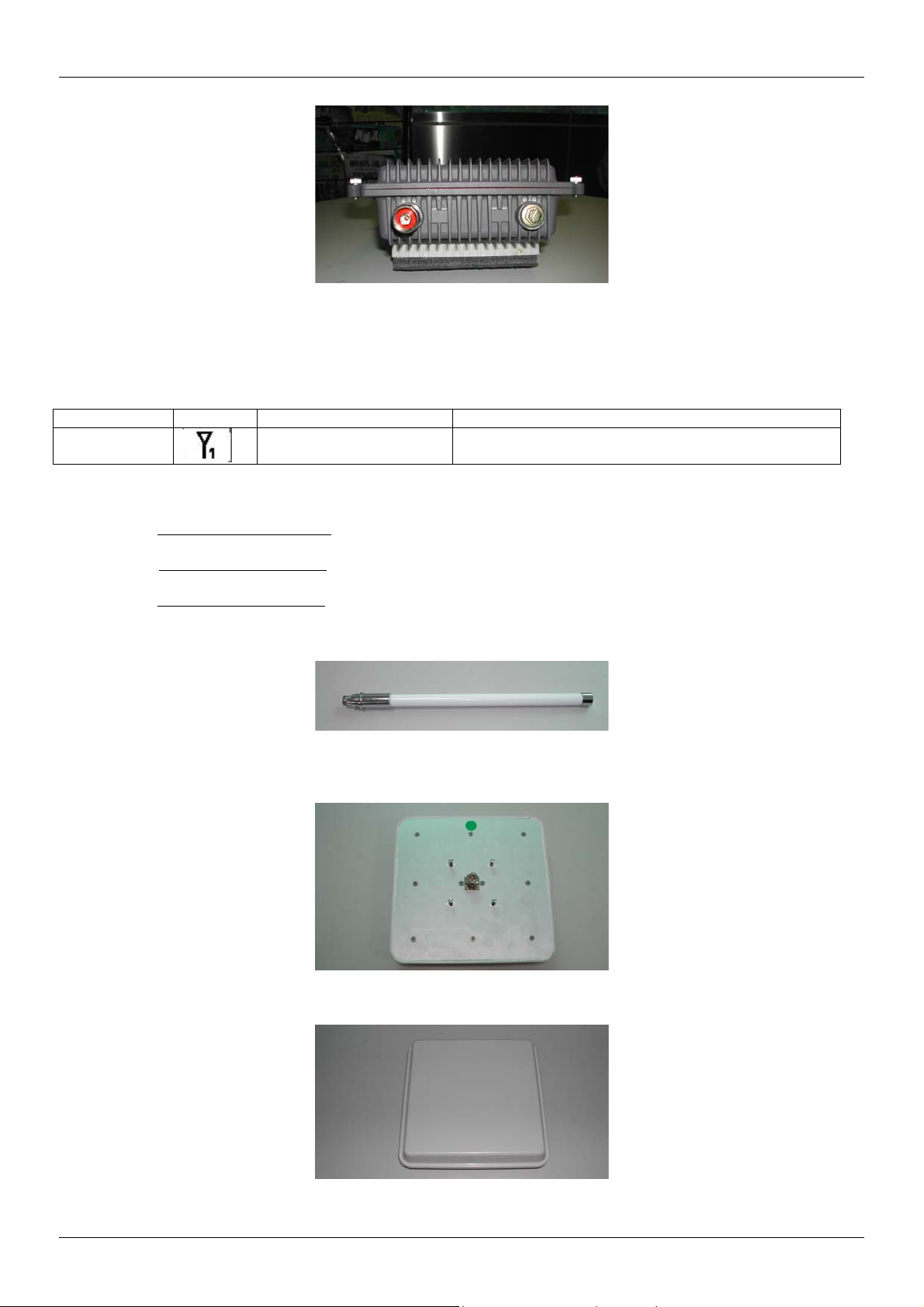
3. RF cable
The RF cable is used to connect the outdoor unit and the flat panel antenna. HDF 400 type RF cable with 2m
length is provided. The appearance of the RF cable is shown below.
ExpWave 240B Secure Outdoor Ethernet Radio Link
Figure 2-6 Front view of flat panel antenna
Figure 2-7 HDF 400 RF cable
4. RS-232 cable
The RS-232 cable is used to connect the console port of the outdoor unit and the antenna alignment kit or
the workstation. The appearance of the RS-232 cable is shown below.
Figure 2-8 RS-232 console cable
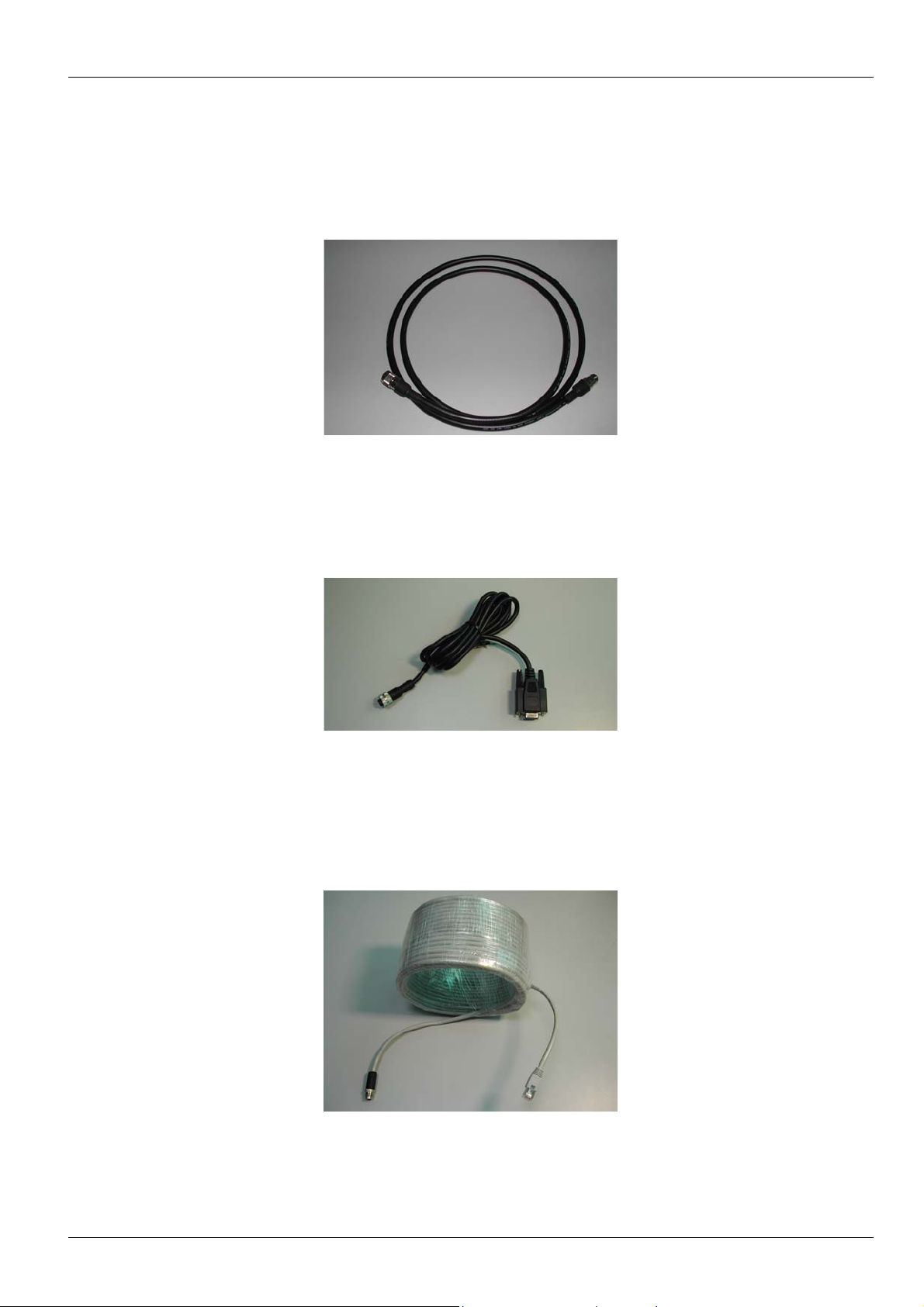
5. Cat-5 cable with special connector
The Cat-5 cable with special connector has 20m in length. It is used to provide the path to deliver power for
the outdoor unit and the data communication. The optional cable length of 50m, and 90m are also available
for specified application. The appearance is shown below.
Figure 2-9 Category 5 cable
Hardware Installation 2-3
Page 26

ExpWave 240B Secure Outdoor Ethernet Radio Link
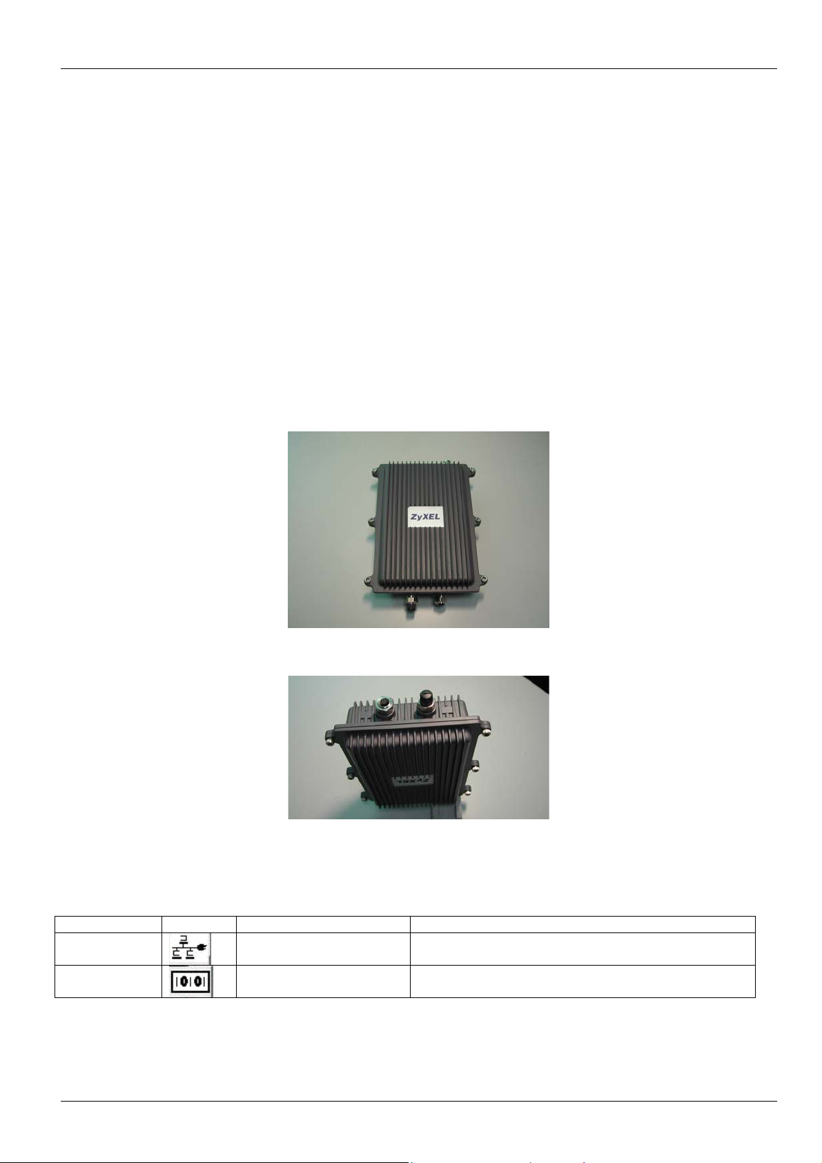
6. Grounding wire
The grounding wire is used to provide the grounding path for the outdoor unit to minimize the impact of
lightening and surge. The physical appearance of the grounding wire is shown below.
Figure 2-10 Grounding wire
7. Mounting bracket
The mounting kit is used to provide a good support for the outdoor unit and the flat panel antenna. Please
follow the installation procedure to mount the outdoor unit and the flat panel antenna. The contents of the
mounting kit are shown below.
Figure 2-11 The Mounting kit
8. Network/Power Injector
The network /power injector is used to combine the data stream and power into one cable. It has three ports.
The port named POWER
is for 48V power from the switching power adapter. The port named TO LAN is
connected the customer premises equipment (CPE) by Cat-5 cable. The port named TO RADIO is
connected to the outdoor unit by the cable described in item 5.
The appearance of the network/power injector is shown below.
Figure 2-12 Network/Power Injector
9. Antenna Alignment Kit (Option)
Two ExpWave 240B with the flat panel antennas should perform antenna alignment before the normal
operation. If the antenna alignment is not done well, the received signal strength will be smaller and the link
quality will be not good enough to support high-speed data communication. The antenna alignment kit is
connected to the outdoor unit through the RS-232 cable. You should modify the vertical and horizontal angle
of the panel antenna according to the signal strength indication of the antenna alignment. The physical
appearance of the antenna alignment is shown below.
2-4 Hardware Installation
Page 27
ExpWave 240B Secure Outdoor Ethernet Radio Link
Figure 2-13 Antenna Alignment Kit
10. CAT-5 Straight-through Ethernet cable
The CAT-5 cable is 2m in length. This cable is used to connect the network/power injector and the CPE. The
picture of this cable is shown below.
Figure 2-14 Ethernet Cable
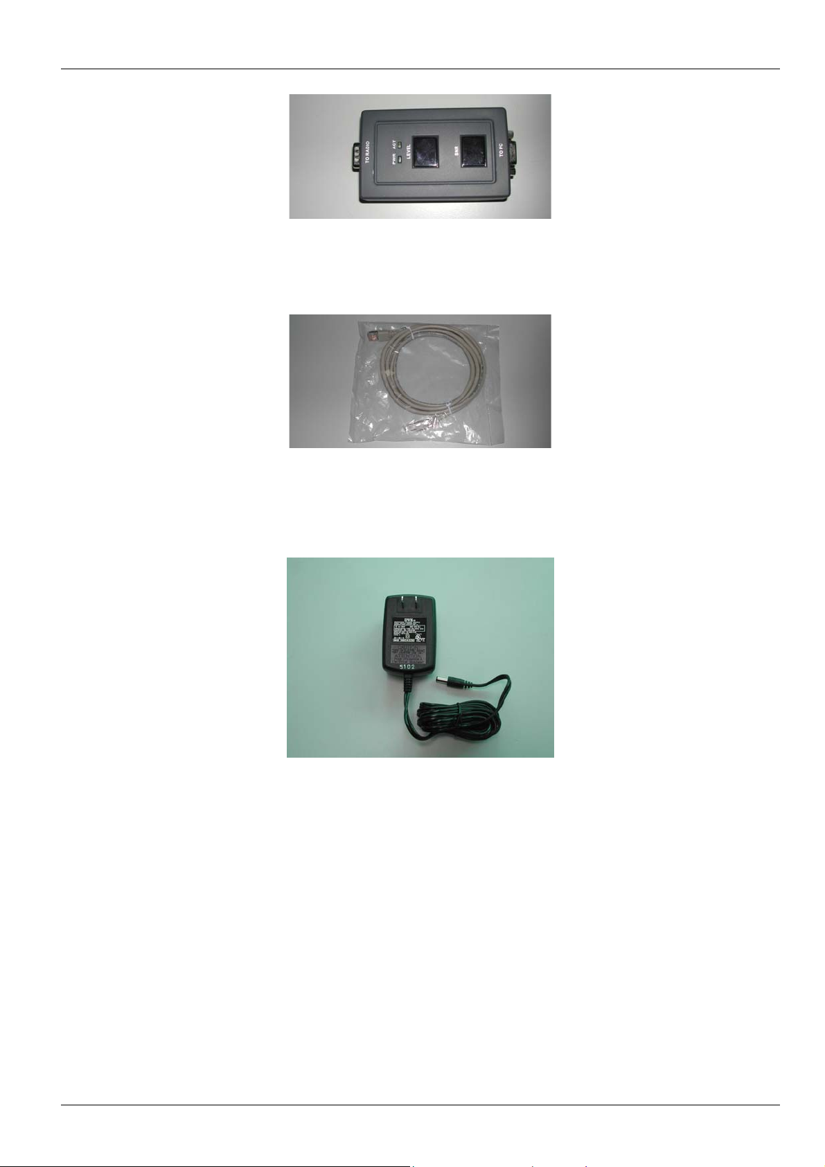
11. Switching Power Adapter
The switching power adapter is to supply the power for the outdoor unit. The input to this adapter is
100~240VAC and the output is 48VDC. The picture is shown below.
Figure 2-15 Switching Power Adaptor
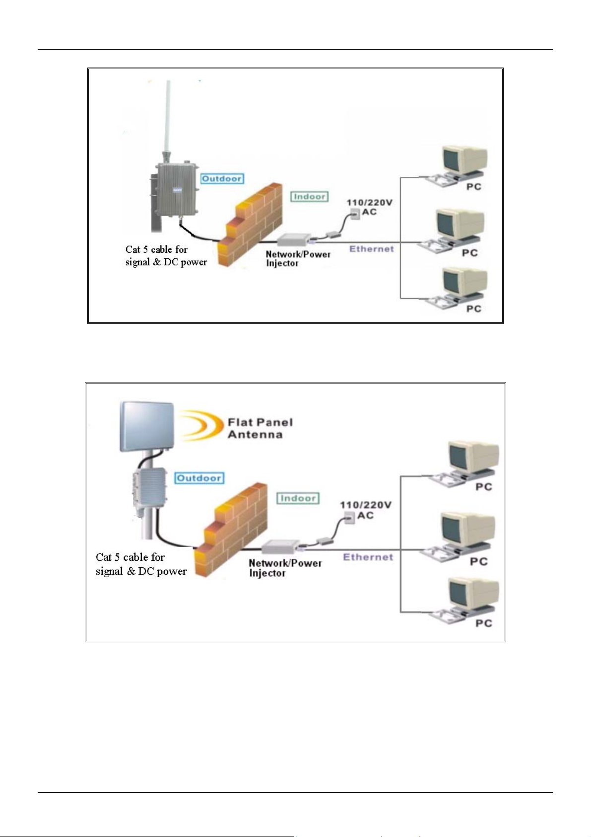
2.2 ExpWave 240B Physical Connection
The physical cable connection of the ExpWave 240B will be shown by the following two pictures.
Hardware Installation 2-5
Page 28
ExpWave 240B Secure Outdoor Ethernet Radio Link
Power
adaptor
Figure 2-16 Physical Installation of ExpWave with Omni-directional antenna
Power
adaptor
Figure 2-17 Physical Installation of ExpWave with flat panel antenna
2.3 Installation Procedure
The installation procedure of ExpWave is described as below:
2-6 Hardware Installation
Page 29

ExpWave 240B Secure Outdoor Ethernet Radio Link
1. The whole installation procedure begins from the indoor to the outdoor installation.
2. Choose an appropriate place for the network/power injector. You might hang it on the wall or just place it
on the desk.
3. Connect the TO LAN
port of network/power injector and your CPE by the Cat-5 cable (2m in length).
4. Plug the switching power adapter into the 110V/220V outlet. Plug the output 48V into the network/power
injector POWER
5. Connect the TO RADIO
port.
port with Cat-5 cable (20m in length) and pull the special connector end of this
cable to the outdoor.
6. When the antenna alignment at both AP and AC sites are completed or the link is established, the LED
“ACK”
will stop blinking .
7. Assemble the mounting kit like the one shown in the following picture.
Figure 2-18 The mounting kit assembly
8. When the outdoor unit is accompanied with an omni-directional antenna, only one mounting is needed.
When the outdoor unit is accompanied with a flat panel antenna, two mounting kit is needed.
9. Choose an appropriate place for the outdoor unit. The chosen sites you plan to install the ExpWave 240B
should have a clear line-of-sight path.
Install the outdoor unit with the omni-directional antenna
10. Assemble the mounting kit with the outdoor unit and the grounding wire should be connected together.
11. Connect the omni-directional antenna to the antenna port of the outdoor unit.
12. Place this assembled one on a stable rod.
13. Connect the other end of the grounding wire to the ground position.
Install the outdoor unit with the flat panel antenna
14. Assemble the mounting kit with the outdoor unit and the grounding wire should be connected together
15. Connect the RF cable to the antenna port of the outdoor unit.
16. Assemble the mounting kit with the flat panel antenna.
17. Place this flat panel antenna on a stable rod.
18. Place the outdoor unit on this stable rod also.
19. Connect the other end of the RF cable to the flat panel antenna.
20. Connect the other end of the grounding wire to the ground position.
Use the antenna alignment kit AK-100 to maximize the signal strength.
21. Open the cover of the console port of the access client unit.
Hardware Installation 2-7
Page 30

ExpWave 240B Secure Outdoor Ethernet Radio Link
22. Connect the RS-232 cable to this console port.
23. Connect the other end of the RS-232 cable to the antenna alignment kit.
24. Modify the horizontal angle first to get the maximum reading in the LEVEL
25. Modify the vertical angle to get the maximum reading.
26. After these steps, remove the antenna alignment kit and the RS-232 cable.
27. Put the cover back to the console port.
28. After the antenna alignment all reached their max LEVEL
telnet to AC, you can check the link quality reading in SMT menu, it is recommended to be higher than
40%, and the signal level to be higher than 22% for a successful link. Note that the value is only for your
reference, depending on the radio and application environment, it might be a little bit different.
reading , The ACK will stop blinking, and if you
display section.
2-8 Hardware Installation
Page 31

ExpWave 240B Secure Outdoor Ethernet Radio Link
g
Chapter 3 Initial Setup
This chapter explains how to perform the initial ExpWave setup and gives an overview of SMT menus.
3.1 Network Topology Planning
The ExpWave is designed for business companies to build up a secure Inter-building wireless communication system
between offices’ Ethernet connection. Your ExpWave can not only be applied for Point to Point (PTP) application but
also the Point to Two Points (PT2P) for multi-sites connection. The ExpWave consists of access point (AP) and
access client (AC). The ExpWave access point can communicate with one ExpWave access client for PTP
connection or two ExpWave access clients for PT2P connections on the air. The network topology for PTP and PT2P
wireless connection is shown below.
AC AP
Brid
e Mode
Figure 3-1 ExpWave Networking Topology
There exist two networking operation modes of bridge mode and router mode within the ExpWave. The bridge mode
supports only the PTP connection and the router mode supports both PTP & PT2P connection. You have to
appropriately configure your ExpWave Access Point and Access Client for normal operation according to your
network topology and requirements before physical installation. The operation mode and application instruction is
shown in Table 3-1.
AC1
AC2
AP
Route Mode
Table 3-1 Operation Mode Instruction of ExpWave
Point to Point Point to Two Points
Bridge Mode yes no
Router Mode yes yes
The basic configurations to both bridge mode and router mode are described in following sections.
Initial Setup 3-1
Page 32

ExpWave 240B Secure Outdoor Ethernet Radio Link
Bridge Mode
192.168.80.217 192.168.80.219
80.X 80.X
AP
Wireless
AC
127.1.0.1 127.1.0.33
192.168.80.218
Figure 3-2 Network Topology in Bridge Mode
The basic configurations in bridge mode are described as below:
Step 1. First set AP to Bridge mode. In AP’s Menu 1, set IP Routing = Bridge Mode.
Menu 1 - General Setup
System Name= 240B-AP
Domain Name= ap-n.lab.ZyXEL.com.tw
IP Routing = Bridge Mode
Press ENTER to Confirm or ESC to Cancel:
192.168.80.155
Figure 3-3 Menu 1 – Bridge Mode General Setup
Step 2. In AP’s Menu 3-2, set DHCP=None (if you had dhcp server in the network already), IP address=192.168.80.217,
IP Subnet Mask=255.255.255.0
Menu 3.2 - TCP/IP and DHCP Ethernet Setup
DHCP= None
Configuration:
Client IP Pool Starting Address= N/A
Size of Client IP Pool= N/A
Primary DNS Server= N/A
Secondary DNS Server= N/A
DHCP Server Address= N/A
TCP/IP Setup:
IP Address= 192.168.80.217
IP Subnet Mask= 255.255.255.0
RIP Direction= Both
Version= RIP-1
IP Policies=
Press ENTER to Confirm or ESC to Cancel:
Figure 3-4 Menu 3.2 – TCP/IP and DHCP Ethernet Setup
Step 3. In AP’s Menu 5, set ESSID= Wireless and choice that channel you want to use.
3-2 Initial Setup
Page 33

ExpWave 240B Secure Outdoor Ethernet Radio Link
ESSID= Wireless
Channel ID= CH07 2442 MHz
RTS Threshold= 2432
Frag. Threshold= 2432
WEP= Disable
Default Key= N/A
Key1= N/A
Key2= N/A
Key3= N/A
Key4= N/A
Press Space Bar to Toggle.
Menu 5 – Wireless Setup
Press ENTER to Confirm or ESC to Cancel:
Figure 3-5 Menu 5 – Wireless
Setup
Step 4. In AP’s Menu 6, set AC1 Operation mode=Enabled, Pre_Share Key=951753258, IP=192.168.80.155,
Network Mask=255.255.255.0, MAC Address=00:02:CF:13:46:79 (the same as AC1’s MAC Address)
Menu 6 - Router Mode Network Setup
AP AC1
Operation mode: Enabled
Device ID: 1 2
Pre_Share Key: 951753258
Ethernet (LAN) Setting:
LAN IP: 192.168.80.217 192.168.80.219
Network Mask: 255.255.255.0 255.255.255.0
Wireless (WLAN) Setting:
MAC Address: 00:02:CF:13:46:79
VPN Security: None
Press ENTER to Confirm or ESC to Cancel:
Press Space Bar to Toggle.
Figure 3-6 Menu 6 – Router Mode Network Setup
Step 5. Now set AC the same ESSID=Wireless and Pre_share Key=951753258 in AC’s Menu 5.When AP and AC link
again and AP will send the settings to AC automatically.
Initial Setup 3-3
Page 34

ExpWave 240B Secure Outdoor Ethernet Radio Link
Menu 5 – Wireless Setup
ESSID= Wireless
Channel ID= CH07 2442 MHz
RTS Threshold= 2432
Frag. Threshold= 2432
WEP= Disable
Default Key= N/A
Key1= N/A
Key2= N/A
Key3= N/A
Key4= N/A
Pre_share Key= 951753258
Press Space Bar to Toggle.
Press ENTER to Confirm or ESC to Cancel:
Figure 3-7 Menu 5 – Access Client Wireless Setup
Step 6. in AC, Use Menu 24-8 into CI command mode, type ip ping 192.168.80.217
240B-AC> ip ping 192.168.80.217
Resolving 192.168.80.217... 192.168.80.217
sent rcvd rate rtt avg mdev max min
1 1 100 8 8 0 8 8
2 2 100 4 8 1 8 4
3 3 100 4 8 2 8 4
Figure3-8 IP Ping
Step 7. In the Menu 24-1, it will show the connection status between AP and AC
Router Mode
192.168.80.217
80.X 223.X
AP AC1
Wireless
192.168.80.218
127.1.0.1 127.1.0.33
Figure 3-9 Network Topology in Router Mode
The basic configurations in router mode are described as below:
Step 1. First set AP to Router mode, In AP’s Menu 1, set IP Routing = Router Mode.
Menu 1 - General Setup
System Name= 240B-AP
Domain Name= ap-n.lab.ZyXEL.com.tw
IP Routing = Router Mode
192.168.223.1
192.168.223.33
Press ENTER to Confirm or ESC to Cancel:
Figure 3-10 Router Mode General Setup
Step 2. In AP’s Menu 3-2, set DHCP=None, IP address=192.168.80.217, IP Subnet Mask=255.255.255.0
3-4 Initial Setup
Page 35

ExpWave 240B Secure Outdoor Ethernet Radio Link
Menu 3.2 - TCP/IP and DHCP Ethernet Setup
DHCP= None
Configuration:
Client IP Pool Starting Address= N/A
Size of Client IP Pool= N/A
Primary DNS Server= N/A
Secondary DNS Server= N/A
DHCP Server Address= N/A
TCP/IP Setup:
IP Address= 192.168.80.217
IP Subnet Mask= 255.255.255.0
RIP Direction= Both
Version= RIP-1
IP Policies=
Press ENTER to Confirm or ESC to Cancel:
Figure 3-11 TCP/IP and DHCP Ethernet Setup
Step 3. In AP’s Menu 5, set ESSID= Wireless and Channel ID.
Menu 5 – Wireless Setup
ESSID= Wireless
Channel ID= CH07 2442 MHz
RTS Threshold= 2432
Frag. Threshold= 2432
WEP= Disable
Default Key= N/A
Key1= N/A
Key2= N/A
Key3= N/A
Key4= N/A
Press ENTER to Confirm or ESC to Cancel:
Press Space Bar to Toggle.
Figure 3-12 Wireless Setup
Step 4. In AP’s Menu 6, set AC1 Operation mode=Enabled, Pre_Share Key=951753258, IP=192.168.223.1, Network
Mask=255.255.255.0, MAC Address=00:02:CF:13:46:79 (the same as AC1’s MAC Address), and set DHCP
Edit=YES.
Menu 6 - Router Mode Network Setup
AP AC1 AC2
Operation mode: Enabled Disabled
Device ID: 1 2 N/A
Pre_Share Key: 951753258 N/A
Ethernet (LAN) Setting:
LAN IP: 192.168.80.217 192.168.223.1 N/A
Network Mask: 255.255.255.0 255.255.255.0 N/A
RIP Direction: Both Both N/A
RIP Version: RIP-2B RIP-2B N/A
DHCP Edit: No N/A
Wireless (WLAN) Setting:
MAC Address: 00:02:CF:13:46:79 N/A
VPN Security: None N/A
AC1&AC2 VPN Security: None
Press ENTER to Confirm or ESC to Cancel:
Figure 3-13 Router Mode Network Setup
Initial Setup 3-5
Page 36

ExpWave 240B Secure Outdoor Ethernet Radio Link
Step 5. Set DHCP to server and Client IP Pool Starting Address like 192.168.223.33. You can also setting the Size of Client
IP Pool, Primary DNS and Secondary DNS Server.
Menu 6.1 - AC1 LAN DHCP Setup
DHCP= Server
Configuration:
Client IP Pool Starting Address= 192.168.223.33
Size of Client IP Pool= 32
Primary DNS Server= 0.0.0.0
Secondary DNS Server= 0.0.0.0
Press ENTER to Confirm or ESC to Cancel:
Figure 3-14 AC1 LAN DHCP Setup
Step 6. Now set AC with the same ESSID= Wireless and Pre_share Key= 951753258 in AC’s Menu 5.When AP and AC
link again then AP will send the settings to AC automatically.
ESSID= Wireless
Channel ID= CH07 2442 MHz
RTS Threshold= 2432
Frag. Threshold= 2432
WEP= Disable
Default Key= N/A
Key1= N/A
Key2= N/A
Key3= N/A
Key4= N/A
Pre_share Key= 951753258
Press Space Bar to Toggle.
Menu 5 – Wireless Setup
Press ENTER to Confirm or ESC to Cancel:
Figure 3-15 Menu 5 - Wireless Setup
Step 7. In AC, Use Menu 24-8 into CI command, type ip ping 192.168.80.217
240B-AC> ip ping 192.168.80.217
Resolving 192.168.80.217... 192.168.80.217
sent rcvd rate rtt avg mdev max min
1 1 100 8 8 0 8 8
2 2 100 4 8 1 8 4
3 3 100 4 8 2 8 4
Figure 3-16 IP Ping
Step 8. In the menu 24-1, it will show the connection status between AP and AC.
3.2 Turning On ExpWave
3-6 Initial Setup
Page 37

ExpWave 240B Secure Outdoor Ethernet Radio Link
[UP]/[
At this point, you should have connected the console port, the RF (Antenna) port, the LAN port, and the power port to
the appropriate devices or lines. While connecting power adaptor into outlet, the PWR LED of your Network/Power
injector turns on. The ACT LED of Network/Power injector turns on while the outdoor radio unit operates well.
3.2.1 Initial Screen
When you turn on your ExpWave, it performs several internal tests as well as line initialization. After the tests, the
ExpWave display as follow, you can press [ENTER] to continue, as shown next.
Copyright (c) 1994 - 2002 ZyXEL Communications Corp.
initialize ch =0, ethernet address: 00:02:CF:95:18:51
initialize ch =1, v2.5/3.0 card OK. ethernet address: 00:02:CF:95:18:52
adjust TCP mss on enif0 to 1400
Figure 3-17 Initial Screen
3.2.2 Entering the Password
The login screen appears after you press [ENTER], prompting you to enter the password, as shown below.
For your first login, enter the default password “1234”. As you type the password, the screen displays an (X) for each
character you type.
Please note that if there is no activity for longer than five minutes after you log in, your ExpWave will automatically log
you out and display a blank screen. If you see a blank screen, press [ENTER] to bring up the login screen again.
Enter Password : XXXX
Figure 3-18 Password Screen
3.3 Navigating the SMT Interface
The SMT (System Management Terminal) is the interface that you use to configure your ExpWave.
Several operations that you should be familiar with before you attempt to modify the configuration are listed in the
table below.
Table 3-2 Main Menu Commands
OPERATION KEYSTROKES DESCRIPTION
Move down to
another menu
Move up to a
previous menu
Move to a
“hidden” menu
Move the cursor [ENTER] or
[ENTER] To move forward to a submenu, type in the number of the desired
submenu and press [ENTER].
[ESC] Press the [ESC] key to move back to the previous menu.
Press [SPACE BAR] to
change No to Yes then
press [ENTER].
DOWN] arrow
Fields beginning with “Edit” lead to hidden menus and have a default
setting of No. Press [SPACE BAR] to change No to Yes, then press
[ENTER] to go to a “hidden” menu.
Within a menu, press [ENTER] to move to the next field. You can
also use the [UP]/[DOWN] arrowkeys to move to the previous and
Initial Setup 3-7
Page 38

ExpWave 240B Secure Outdoor Ethernet Radio Link
OPERATION KEYSTROKES DESCRIPTION
keys the next field, respectively.
Entering
information
Required fields
Fill in, or press
[SPACE BAR], then
press [ENTER] to
select from choices.
? >
<
You need to fill in two types of fields. The first requires you to type in
the appropriate information. The second allows you to cycle through
the available choices by pressing [SPACE BAR].
All fields with the symbol <?> must be filled in order be able to save
the new configuration.
N/A fields <N/A> Some of the fields in the SMT will show a <N/A>. This symbol refers
to an option that is Not Applicable.
Save your
configuration
[ENTER] Save your configuration by pressing [ENTER] at the message “Press
ENTER to confirm or ESC to cancel”. Saving the data on the screen
will take you, in most cases to the previous menu.
Exit the SMT Type 99, then press
[ENTER].
Type 99 at the main menu prompt and press [ENTER] to exit the
SMT interface.
3.3.1 Main Menu (Routing AP)
After you enter the password, the SMT displays the ExpWave Main Menu, as shown next.
Getting Started Advanced Management
1. General Setup
3. LAN Setup
5. Wireless Setup
6. Network Setup
Advanced Applications
12. Static Routing Setup
Enter Menu Selection Number:
Copyright (c) 1994 - 2002 ZyXEL Communications Corp.
ExpWave 240B-AP Main Menu
21. Filter and Firewall Setup
22. SNMP Configuration
23. System Password
24. System Maintenance
25. IP Routing Policy
99. Exit
Figure 3-19 ExpWave Main Menu
3.3.2 Summaries of SMT Menu
Table 3-3 Main Menu Summary
NO. MENU TITLE FUNCTION
1 General Setup Use this menu to set up dynamic DNS and administrative information.
3 LAN Setup Use this menu to apply LAN filters, configure LAN DHCP and TCP/IP
settings.
5 Wireless Setup Use this menu to configure your wireless settings
6 Network Setup Use this menu to set up the point-to-point network.
12 Static Routing Setup Configure IP static routes in this menu.
21 Filter Setup Configure filters.
3-8 Initial Setup
Page 39

ExpWave 240B Secure Outdoor Ethernet Radio Link
NO. MENU TITLE FUNCTION
22 SNMP Configuration Use this menu to configure SNMP-related parameters.
23 System Password Change your password in this menu (recommended).
24 System Maintenance From displaying system status to uploading firmware, this menu provides
comprehensive system maintenance.
25 IP Routing Policy Setup Use this menu to configure policies for use in IP policy routing.
99 Exit Use this menu to exit (necessary for remote configuration).
3.4 Changing the System Password
Change the default system password by following the steps shown next.
Step 1. Enter 23 in the main menu to open Menu 23 - System Password as shown next.
Menu 23 - System Password
Old Password= ?
New Password= ?
Retype to confirm= ?
Enter here to CONFIRM or ESC to CANCEL:
Figure 3-20 Menu 23 — System Password
Step 2. Type your existing password and press [ENTER].
Step 3. Type your new system password and press [ENTER].
Step 4. Re-type your new system password for confirmation and press [ENTER].
Note that as you type a password, the screen displays an (X) for each character you type.
Initial Setup 3-9
Page 40

Page 41

ExpWave 240B Secure Outdoor Ethernet Radio Link
Chapter 4 Menu 1 - General Setup
Menu 1 - General Setup contains administrative and system-related information.
4.1 System Name
System Name is for identification purposes. ZyXEL recommends you enter your computer’s “Computer name”.
• In Windows 95/98 click Start -> Settings -> Control Panel and then double-click Network. Click the
Identification tab, note the entry for the Computer name field and enter it in the ExpWave System Name
field.
• In Windows 2000 click Start->Settings->Control Panel and then double-click System. Click the Network
Identification tab and then the Properties button. Note the entry for the Computer name field and enter it in
the ExpWave System Name field.
• In Windows XP, click start -> My Computer -> View system information and then click the Computer
Name tab. Note the entry in the Full computer name field and enter it as the ExpWave System Name.
The Domain Name entry is what is propagated to the DHCP clients on the LAN. If you leave this field blank, the
domain name obtained by DHCP from the ISP is used. While you must enter the host name (System Name) on each
individual machine, the domain name can be assigned from the ExpWave via DHCP.
4.2 General Setup
Step 1. Enter 1 in the main menu to open Menu 1 — General Setup.
Step 2. The Menu 1 - General Setup screen appears, as shown next. Fill in the required fields.
Menu 1 - General Setup
System Name= 240B-AP
Domain Name= ap-n.lab.ZyXEL.com.tw
IP Routing = Router Mode
Press ENTER to Confirm or ESC to Cancel:
Figure 4-1 Menu 1 — General Setup
Table 4-1 General Setup Menu Field
FIELD DESCRIPTION EXAMPLE
System Name Choose a descriptive name for identification purposes. It is
recommended you enter your computer’s “Computer name” (see
section 0) in this field. This name can be up to 30 alphanumeric
characters long. Spaces are not allowed, but dashes “-” and
underscores "_" are accepted.
Domain Name Enter the domain name (if you know it) here. If you leave this field
blank, the ISP may assign a domain name via DHCP. You can go to
menu 24.8 and type "sys domain name" to see the current domain
name used by your router.
If you want to clear this field just press [SPACE BAR] and then
[ENTER]. The domain name entered by you is given priority over the
ISP assigned domain name.
IP Routing
Press [SPACE BAR] and then [ENTER] to select Router or Bridge.
Select Bridge to set AP and AC work as bridge ,Router to set AP and
240B-AP
ap-n.lab.ZyXEL.com
.tw
General Setup 4-1
Page 42

ExpWave 240B Secure Outdoor Ethernet Radio Link
AC work as bridge.
When you have completed this menu, press [ENTER] at the prompt “Press ENTER to Confirm…” to save
your configuration, or press [ESC] at any time to cancel.
4-2 General Setup
Page 43

This chapter describes how to configure the LAN using Menu 3 — LAN Setup.
5.1 Introduction
From the main menu, enter 3 to open Menu 3 – LAN Setup.
ExpWave 240B Secure Outdoor Ethernet Radio Link
Chapter 5 LAN Setup
Menu 3 - LAN Setup
1. LAN Port Filter Setup
2. LAN DHCP Setup
Enter Menu Selection Number:
Figure 5-1 Menu 3 — LAN Setup
5.2 LAN Port Filter Setup
This menu allows you to specify the filter sets that you wish to apply to the LAN traffic. You seldom need to filter the
LAN traffic, however, the filter sets may be useful to block certain packets, reduce traffic and prevent security
breaches.
Input Filter Sets:
Menu 3.1 – LAN Port Filter Setup
protocol filters=
device filters=
Output Filter Sets:
protocol filters=
device filters=
Press ENTER to Confirm or ESC to Cancel:
Figure 5-2 Menu 3.1 — LAN Port Filter Setup
5.3 LAN DHCP
The ExpWave has built-in DHCP server capability that assigns IP addresses and DNS servers to systems that
support DHCP client capability.
Wireless Setup 5-1
Page 44

ExpWave 240B Secure Outdoor Ethernet Radio Link
5.3.1 Factory LAN Defaults
The LAN parameters of the ExpWave are preset in the factory with the following values:
1. IP address of 192.168.1.1 with subnet mask of 255.255.255.0 (24 bits).
2. DHCP server enabled with 32 clients IP addresses starting from 192.168.1.33.
These parameters should work for the majority of installations. If your ISP gives you an explicit DNS server address
(es), skip ahead to section xxxx to see how to enter the DNS server address(es).
5.3.2 DHCP Configuration
DHCP (Dynamic Host Configuration Protocol, RFC 2131 and RFC 2132) allows individual clients to obtain TCP/IP
configuration at start-up from a server. You can configure the ExpWave as a DHCP server or disable it. When
configured as a server, the ExpWave provides the TCP/IP configuration for the clients. If set to None, DHCP service
will be disabled and you must have another DHCP server on your LAN, or else the computer must be manually
configured.
IP Pool Setup
The ExpWave is pre-configured with a pool of 32 IP addresses ranging from 192.168.1.33 to 192.168.1.64. This
configuration leaves 31 IP addresses (excluding the ExpWave itself) in the lower range for other server machines,
e.g., server for mail, FTP, Telnet, web, etc., that you may have.
DNS Server Address
Use DNS to map a domain name to its corresponding IP address and vice versa, for example, the IP address of
www.ZyXEL.com.tw is 210.243.128.9. The DNS server is extremely important because without it, you must know the
IP address of a machine before you can access it.
There are two ways that an ISP disseminates the DNS server addresses.
The first is for an ISP to tell a customer the DNS server addresses, usually in the form of an information sheet, when
you sign up. If your ISP gives you DNS server addresses, enter them in the DNS Server fields in DHCP Setup.
The second is to leave this field blank, i.e., 0.0.0.0 — in this case, the ExpWave acts as a DNS proxy.
Table 5-1 Example Of Network Properties For LAN Servers With Fixed IP Addresses
Choose an IP address 192.168.1.2 - 192.168.1.32; 192.168.1.65 - 192.168.1.254
Subnet mask 255.255.255.0
Gateway (or default route) 192.168.1.1 (ExpWave LAN IP Address)
5.3.3 IP Address and Subnet Mask
Similar to the way houses on a street share a common street name, so too do machines on a LAN share one common
network number.
Where you obtain your network number depends on your particular situation. If the ISP or your network administrator
assigns you a block of registered IP addresses, follow their instructions in selecting the IP addresses and the subnet
mask.
If the ISP did not explicitly give you an IP network number, then most likely you have a single user account and the
ISP will assign you a dynamic IP address when the connection is established. Once you have decided on the network
number, pick an IP address that is easy to remember, for example192.168.1.1, for your ExpWave, but make sure that
no other device on your network is using that IP address.
5-2 Wireless Setup
Page 45

ExpWave 240B Secure Outdoor Ethernet Radio Link
The subnet mask specifies the network number portion of an IP address. Your ExpWave will compute the subnet
mask automatically based on the IP address that you entered. You don’t need to change the subnet mask computed
by the ExpWave unless you are instructed to do otherwise.
Private IP Addresses
Every computer on the Internet must have a unique IP address. If your networks are isolated from the Internet, for
example, only between your two branch offices, you can assign any IP addresses to the hosts without problems.
However, the Internet Assigned Numbers Authority (IANA) has reserved the following three blocks of IP addresses
specifically for private networks:
Table 5-2 Private IP Address Ranges
10.0.0.0 — 10.255.255.255
172.16.0.0 — 172.31.255.255
192.168.0.0 — 192.168.255.255
You can obtain your IP address from the IANA, from an ISP or have it assigned by a private network. If you belong to
a small organization and your Internet access is through an ISP, the ISP can provide you with the Internet addresses
for your local networks. On the other hand, if you are part of a much larger organization, you should consult your
network administrator for the appropriate IP addresses.
Regardless of your particular situation, do not create an arbitrary IP address; always follow the guidelines
above. For more information on address assignment, please refer to RFC 1597, Address Allocation for
Private Internets and RFC 1466, Guidelines for Management of IP Address Space.
5.3.4 RIP Setup
RIP (Routing Information Protocol, RFC1058 and RFC 1389) allows a router to exchange routing information with
other routers. The RIP Direction field controls the sending and receiving of RIP packets. When set to Both or Out
Only, the ExpWave will broadcast its routing table periodically. When set to Both or In Only, it will incorporate the
RIP information that it receives; when set to None, it will not send any RIP packets and will ignore any RIP packets
received.
The Version field controls the format and the broadcasting method of the RIP packets that the ExpWave sends (it
recognizes both formats when receiving). RIP-1 is universally supported; but RIP-2 carries more information. RIP-1 is
probably adequate for most networks, unless you have an unusual network topology.
Both RIP-2B and RIP-2M sends the routing data in RIP-2 format; the difference being that RIP-2B uses subnet
broadcasting while RIP-2M uses multicasting. Multicasting can reduce the load on non-router machines since they
generally do not listen to the RIP multicast address and so will not receive the RIP packets. However, if one router
uses multicasting, then all routers on your network must use multicasting, also.
By default, RIP Direction is set to Both and the Version set to RIP-1.
5.4 LAN Setup Menu
From the main menu, enter 3 to open Menu 3 - LAN Setup to configure TCP/IP (RFC 1155) and DHCP Ethernet
setup.
Wireless Setup 5-3
Page 46

ExpWave 240B Secure Outdoor Ethernet Radio Link
y
Menu 3 - LAN Setup
1. LAN Port Filter Setup
2. LAN DHCP Setup
Enter Menu Selection Number:
Figure 5-3 Menu 3 - LAN DHCP Setup
From menu 3, select the submenu option TCP/IP and DHCP Setup and press [ENTER]. The screen now displays
Menu 3.2 — TCP/IP and DHCP Ethernet Setup, as shown next.
Menu 3.2 - TCP/IP and DHCP Ethernet Setup
DHCP= Server
Configuration:
Client IP Pool Starting Address= 192.168.1.33
Size of Client IP Pool= 32
Primary DNS Server= 0.0.0.0
Secondary DNS Server= 0.0.0.0
DHCP Server Address= N/A
TCP/IP Setup:
IP Address= 192.168.1.1
IP Subnet Mask= 255.255.255.0
RIP Direction= Both
Version= RIP-1
IP Policies= 2,7,9,11
Press ENTER to Confirm or ESC to Cancel:
in the IP Pool
Size of the IP
Pool
IP addresses
of the DNS
servers
First address
Figure 5-4 Menu 3.2 - LAN DHCP Ethernet Setup
Follow the instructions in the next table on how to configure the DHCP fields.
Table 5-3 DHCP Ethernet Setup Menu Fields
FIELD DESCRIPTION EXAMPLE
DHCP This field enables/disables the DHCP server.
If set to Server, your ExpWave will act as a DHCP server.
If set to None, the DHCP server will be disabled.
If set to Relay, the ExpWave acts as a surrogate DHCP server and relays
requests and responses between the remote server and the clients.
When set to Server, the following items need to be set:
Configuration:
Client IP Pool
Starting
Address
Size of Client
IP Pool
Primary DNS
Server
Secondar
This field specifies the first of the contiguous addresses in the IP address
pool.
This field specifies the size, or count of the IP address pool. 32
Type the IP addresses of the DNS servers. The DNS servers are passed
to the DHCP clients along with the IP address and the subnet mask.
Server
192.168.1.
33
5-4 Wireless Setup
Page 47

ExpWave 240B Secure Outdoor Ethernet Radio Link
FIELD DESCRIPTION EXAMPLE
DNS Server
DHCP Server
Address
If Relay is selected in the DHCP field above, then type the IP address of
the actual, remote DHCP server here.
Follow the instructions in the following table to configure TCP/IP parameters for the LAN port.
Table 5-4 LAN TCP/IP Setup Menu Fields
FIELD DESCRIPTION EXAMPLE
TCP/IP Setup:
IP Address Enter the IP address of your ExpWavein dotted decimal notation 192.168.1.1
(default)
IP Subnet Mask Your ExpWavewill automatically calculate the subnet mask based
on the IP address that you assign. Unless you are implementing
subnetting, use the subnet mask computed by the ExpWave.
RIP Direction Press [SPACE BAR] and then [ENTER] to select the RIP direction.
Options are: Both, In Only, Out Only or None.
Version Press [SPACE BAR] and then [ENTER] to select the RIP version.
Options are:
RIP-1, RIP-2B or RIP-2M.
255.255.255
Both
(default)
RIP-1
(default)
.0
When you have completed this menu, press [ENTER] at the prompt [Press ENTER to Confirm…] to save
your configuration, or press [ESC] at any time to cancel.
IP Policies You can apply up to four IP Policy sets (from twelve) by typing their
numbers separated by commas.
2,7,9,11
Wireless Setup 5-5
Page 48

Page 49

ExpWave 240B Secure Outdoor Ethernet Radio Link
p
Chapter 6 Wireless Setup
This chapter describes how to configure the Wireless operation using Menu 5 — Wireless Setup.
From the main menu, enter 5 to open Menu 5 –Wireless Setup.
The ExpWave AP forces the ExpWave AC into an unauthorized state that allows the AC to send only an EAP start
message. The AP returns an EAP message requesting the user's identity. The AC returns the identity, which is then
forwarded by the AP to the authentication server, which uses an algorithm to authenticate the user and then returns
an accept or reject message back to the AP. Assuming an accept was received, the AP changes the client's state to
authorized and normal traffic can now take place.
ESSID= Wireless
Channel ID= CH07 2442 MHz
RTS Threshold= 2432
Frag. Threshold= 2432
WEP= Disable
Default Key= N/A
Key1= N/A
Key2= N/A
Key3= N/A
Key4= N/A
Press Space Bar to Toggle.
Menu 5 – Wireless Setup
Press ENTER to Confirm or ESC to Cancel:
Figure 6-1 Wireless Setup
Table 6-1 Wireless LAN Setup Menu Fields
FIELD DESCRIPTION EXAMPLE
ESSID (Extended Service Set IDentification) The ESSID identifies the
Service Set the station is to connect to. Wireless clients associating
to the Access Point must have the same ESSID. Enter a descriptive
name for the wireless LAN. This field can be up to 32 characters.
Channel ID This allows you to set the operating frequency/channel depending on
your particular region. Use [space bar] to toggle.
• CH01 2412 MHz / CH02 2417 MHz ~ CH11 2462 MHz (North
America/FCC)
• CH01 2412 MHz / CH02 2417 MHz ~ CH13 2472 MHz (Europe
CE/ ETSI)
• CH01 2412 MHz / CH02 2417 MHz ~ Ch14 2484 MHz (Japan)
• CH10 2457 MHz / CH11 2462 MHz (Spain)
• CH10 2457 MHz / CH11 2462 MHz ~ CH13 2472 MHz (France)
RTS
Threshold
Frag.
Threshold
WEP (Wired Equivalent Privacy) To prevent unauthorized wireless stations
(Request To Send) The threshold (number of bytes) for enabling
RTS/CTS handshake. Data with its frame size larger than this value
will perform the RTS/CTS handshake. Setting this attribute to be
larger than the maximum MSDU (MAC service data unit) size shall
have the effect of turning off the RTS/CTS handshake. Setting this
attribute to zero shall have the effect of turning on the RTS/CTS
handshake. Enter a value between 0 and 2432.
The threshold (number of bytes) for the fragmentation boundary for
directed messages. Data will be transmitted in fragments with its size
not exceeding this value. Enter a value between 256 and 2432. The
value of this attribute shall never be less than 256.
from accessing data transmitted over the network, the ExpWave 316
offers a data encryption, known as WEP to help encrypt wireless data
transmitted via wireless medium. Disable allows wireless ada
ters to
Wireless
CH01 2412
MHz
2432
(default)
2432
(default)
Disable /
64-bit WEP /
128-bit WEP
Wireless Setup 6-1
Page 50

ExpWave 240B Secure Outdoor Ethernet Radio Link
FIELD DESCRIPTION EXAMPLE
communicate with the Access Points without any data encryption.
Select 64-bit WEP1 or 128-bit WEP to allow data encryption. Although
WEP is functional at 5.5 and 11 Mbps, there is significant performance
degradation when using WEP at these rates.
Default Key This allows you to select one WEP key as an active key to encrypt
wireless data transmission.
Key1 to Key4
When you have completed this menu, press [Enter] at the prompt [Press ENTER to Confirm…] to save
your configuration, or press [Esc] at any time to cancel.
If you choose 64-bit WEP, then enter any 5 characters (ASCII string)
or 10 hexadecimals digits (“0-9”, “A-F”) preceded by 0x for each Key
(1-4).
If you choose 128-bit WEP, then enter any 13 characters (ASCII
string) or 26 hexadecimals digits (“0-9”, “A-F”) preceded by 0x for
each Key (1-4).
There are four data encryption keys to secure your data from being
eavesdropped by unauthorized wireless users. The values must be
set up exactly the same on the Access Points as they are on the
wireless client stations. The same value must be assigned to Key 1
on both the Access Point and the client adapters, the same value
must be assigned to Key 2 on both the Access Point and the client
stations and so on, for all four WEP keys.
N/A / 1/2/3/4
********
6-2 Wireless Setup
Page 51

Chapter 7 Network Setup
This chapter describes how to configure the Network Setup using Menu 6 — Network Setup.
7.1 Introduction
From the main menu, enter 6 to open Menu 6 – Network Setup.
Menu 6 - Router Mode Network Setup
AP AC1 AC2
Operation mode: Enabled Disabled
Device ID: 1 2 N/A
Pre_Share Key: 951753258 N/A
Ethernet (LAN) Setting:
LAN IP: 192.168.80.217 192.168.223.1 N/A
Network Mask: 255.255.255.0 255.255.255.0 N/A
RIP Direction: Both Both N/A
RIP Version: RIP-2B RIP-2B N/A
DHCP Edit: No N/A
Wireless (WLAN) Setting:
MAC Address: 00:02:CF:13:46:79 N/A
VPN Security: None N/A
AC1&AC2 VPN Security: High
Press ENTER to Confirm or ESC to Cancel:
Press Space Bar to Toggle.
ExpWave 240B Secure Outdoor Ethernet Radio Link
Figure 7-1 Menu 6 - Router Mode Network Setup and Status
Table 7-1 Network Setup Field
FIELD DESCRIPTION
Operation Mode
Device ID AP set to 1 , AC1 set to 2 , AC2 set to 3.
Pre_Share Key Set the key for AP to AC make authentication.
Ethernet (LAN) Setting
LAN IP Enter the IP address of device lan port in dotted decimal notation.
Network Mask Device will automatically calculate the subnet mask based on the IP
RIP Directio
RIP Version Press the [SPACE BAR] to select the RIP version from
DHCP Edit
Wireless (WLAN) Setting
MAC Address Indicate the station with the same mac address will only be accepted to
VPN Security
AC1 & AC2 VPN
Security
Set AC Enable or Disable.
address that you assign. Unless you are implementing subnetting, use the
subnet mask computed by the Devie.
Press the [SPACE BAR] to select the RIP direction from Both/In
Only/Out Only/None.
RIP-1/RIP-2B/RIP-2M.
Type space bar change Yes or No , if select Yes and enter SMT6.1.
join in.
Set security level (None, Low , Medium , High) for AP and AC conection
Set security level (None, Low , Medium , High) for AC1 and AC2
connection
The VPN security level parameters of authentication & encryption are described in Table 7-2:
Network Setup 7-1
Page 52

ExpWave 240B Secure Outdoor Ethernet Radio Link
Table 7-2 VPN security level
VPN Level Authentication Encryption
None None None
Low MD5 None
Medium MD5 DES
High MD5 3DES
7.2 SMT 6.1 Menu in Router Mode
Menu 6.1 - ACx LAN DHCP Setup
DHCP= Server
Configuration:
Client IP Pool Starting Address= 192.168.223.33
Size of Client IP Pool= 32
Primary DNS Server= 0.0.0.0
Secondary DNS Server= 0.0.0.0
Press ENTER to Confirm or ESC to Cancel:
First address
in the IP Pool
Size of the IP
Pool
IP addresses
of the DNS
servers
Figure 7-2 AC LAN DHCP Setup
Table 7-3 AC LAN DHCP Setup Menu Fields
FIELD DESCRIPTION EXAMPLE
DHCP This field enables/disables the DHCP server.
If set to Server, your ExpWave will act as a DHCP server.
If set to None, the DHCP server will be disabled.
When set to Server, the following items need to be set:
Client IP Pool
Starting Address
Size of Client IP
This field specifies the first of the contiguous addresses in the
IP address pool.
This field specifies the size, or count, of the IP address pool. 32
Pool
Primary DNS Server
Secondary DNS
Server
Enter the IP addresses of the DNS servers. The DNS servers
are passed to the DHCP clients along with the IP address and
the subnet mask. Leave these entries at 0.0.0.0 if they are
provided by an Internet DHCP server.
Server
(default)
192.168.1.33
7-2 Network Setup
Page 53

ExpWave 240B Secure Outdoor Ethernet Radio Link
Chapter 8 Static Route Setup
This chapter shows you how to configure static routes with your ExpWave.
8.1 Introduction
Static routes tell the ExpWave routing information that it cannot learn automatically through other means. This can
arise in cases where RIP is disabled on the LAN.
Each remote node specifies only the network to which the gateway is directly connected, and the ExpWave has no
knowledge of the networks beyond. For instance, the ExpWave knows about network N2 in the following diagram
through remote node Router 1. However, the ExpWave is unable to route a packet to network N3 because it doesn't
know that there is a route through the same remote node Router 1 (via gateway Router 2). The static routes are for
you to tell the ExpWave about the networks beyond the remote nodes.
Figure 8-1 Example of Static Routing Topology
8.2 IP Static Route Setup
You configure IP static routes in menu 12. 1, by selecting one of the IP static routes as shown below. Enter 12 from
the main menu.
Menu 12 - IP Static Route Setup
1. ________
2. ________
3. ________
4. ________
5. ________
6. ________
7. ________
8. ________
Enter selection number:
Figure 8-2 Menu 12 — IP Static Route Setup
Static Route Setup 8-1
Page 54

ExpWave 240B Secure Outdoor Ethernet Radio Link
Now, enter the index number of one of the static routes you want to configure.
Menu 12.1 - Edit IP Static Route
Route #: 1
Route Name= ?
Active= No
Destination IP Address= ?
IP Subnet Mask= ?
Gateway IP Address= ?
Metric= 2
Private= No
Press ENTER to CONFIRM or ESC to CANCEL:
Figure 8-3 Menu 12. 1 — Edit IP Static Route
The following table describes the IP Static Route Menu fields.
Table 8-1 IP Static Route Menu Fields
FIELD DESCRIPTION
Route # This is the index number of the static route that you chose in menu 12.
Route Name Enter a descriptive name for this route. This is for identification purposes only.
Active This field allows you to activate/deactivate this static route.
Destination IP
Address
This parameter specifies the IP network address of the final destination. Routing is
always based on network number. If you need to specify a route to a single host, use a
subnet mask of 255.255.255.255 in the subnet mask field to force the network number
to be identical to the host ID.
IP Subnet Mask Enter the IP subnet mask for this destination.
Gateway IP
Address
Enter the IP address of the gateway. The gateway is an immediate neighbor of your
ExpWave that will forward the packet to the destination. On the LAN, the gateway must
be a router on the same segment as your ExpWave; over the WAN, the gateway must
be the IP address of one of the remote nodes.
Metric Metric represents the “cost” of transmission for routing purposes. IP routing uses hop
count as the measurement of cost, with a minimum of 1 for directly connected
networks. Enter a number that approximates the cost for this link. The number need not
be precise, but it must be between 1 and 15. In practice, 2 or 3 is usually a good
number.
Private This parameter determines if the ExpWave will include the route to this remote node in
its RIP broadcasts. If set to Yes, this route is kept private and not included in RIP
broadcast. If No, the route to this remote node will be propagated to other hosts
through RIP broadcasts.
Once you have completed filling in this menu, press [ENTER] at the message “Press ENTER to Confirm…”
to save your configuration, or press [ESC] to cancel.
8-2 Static Route Setup
Page 55

ExpWave 240B Secure Outdoor Ethernet Radio Link
Chapter 9 Filter Setup Configuration
This chapter shows you how to create and apply filters.
9.1 About Filtering
Your ExpWave uses filters to decide whether to allow passage of a data packet and/or to make a call. There are two
types of filter applications: data filtering and call filtering. Filters are subdivided into device and protocol filters, which
are discussed later.
Data filtering screens the data to determine if the packet should be allowed to pass. Data filters are divided into
incoming and outgoing filters, depending on the direction of the packet relative to a port. Data filtering can be applied
on either the WAN side or the LAN side. For incoming packets, your ExpWave applies data filters. Packets are
processed depending upon whether a match is found. The following sections describe how to configure filter sets.
9.1.1 The Filter Structure of the ExpWave
A filter set consists of one or more filter rules. Usually, you would group related rules, e.g., all the rules for NetBIOS,
into a single set and give it a descriptive name. The ExpWave allows you to configure up to twelve filter sets with six
rules in each set, for a total of 72 filter rules in the system. You cannot
within the same set. You can apply up to four filter sets to a particular port to block multiple types of packets. With
each filter set having up to six rules, you can have a maximum of 24 rules active for a single port. See Figure 9-1 Filter
Rule Process for the logic flow when executing an IP filter.
mix device filter rules and protocol filter rules
Fetch Next
Filter Set
Yes
Next Filter Set
Available?
No
Filter Set
Fetch Next
Filter Rule
Yes
Next filter
No
Rule
Available?
No
Execute
Check
Next
Rule
Figure 9-1 Filter Rule Process
Filter Rule
Drop
Start
Packet into
filter
Fetch First
Filter Set
Fetch First
Filter Rule
Active?
Yes
Forward
Accept PacketDrop Packet
Filter Setup 9-1
Page 56

ExpWave 240B Secure Outdoor Ethernet Radio Link
9.2 Configuring a Filter Set
To configure a filter sets, follow the procedure below:
Step 1. Select option 21. Filter Set Configuration from the Main Menu to open Menu 21.
Menu 21 - Filter Set Configuration
Filter
Set #
-----1
2
3
4
5
6
Enter Filter Set Number to Configure= 0
Edit Comments=
Comments
------------------
______________
______________
______________
______________
______________
______________
Press ENTER to CONFIRM or ESC to CANCEL:
Filter
Set #
-----7
8
9
10
11
12
Figure 9-2 Menu 21 - Filter Set Configuration
Comments
-----------------______________
______________
______________
______________
______________
______________
Step 2. Select the filter set you wish to configure (no. 1-12) and press [Enter]
.
Step 3. Enter a descriptive name or comment in the Edit Comments field and press Enter.
Press [Enter] at the message: [Press ENTER to confirm] to open Menu 21.1 - Filter Rules Summary.
Menu 21.1 - Filter Rules Summary
# A Type Filter Rules M m n
- - ---- -------------------------------------------- --------- - - 1 Y IP Pr=17, SA=0.0.0.0, DA=0.0.0.0, DP=53 N D F
2 Y
3 Y
4 Y
5 Y
6 Y
Enter Filter Rule Number (1-6) to Configure:
Figure 9-3 Menu 21.1 - Filter Rules Summary
9.3 Filter Rules Summary Menu
This screen shows the summary of the existing rules in the filter set. The following tables contain a brief description
of the abbreviations used in Menu 21.1.
Table 9-1 Abbreviations Used in the Filter Rules Summary Menu
Abbreviations Description Display
# Refers to the filter rule number (1-6).
A Refers to Active. [Y] means the filter rule is active.
[N] means the filter rule is inactive.
Type Refers to the type of filter rule.
This shows GEN for generic, IP for
[GEN] for Generic
[IP] for TCP/IP
TCP/IP
Filter Rules The filter rule parameters will be
displayed here (see below).
M Refers to More. [Y] means there are more rules to check.
9-2 Filter Setup
Page 57

ExpWave 240B Secure Outdoor Ethernet Radio Link
[N] means there are no more rules to check.
m Refers to Action Matched. [F] means to forward the packet.
[D] means to drop the packet.
[N] means check the next rule.
n Refers to Action Not Matched [F] means to forward the packet.
[D] means to drop the packet.
[N] means check the next rule.
The protocol dependent filter rules abbreviation are listed as follows:
• If the filter type is IP, the following abbreviations listed in the following table will be used.
Table 9-2 Abbreviations Used If Filter Type Is IP
Abbreviation Description
Pr Protocol
SA Source Address
SP Source Port number
DA Destination Address
DP Destination Port number
• If the filter type is GEN (generic), the following abbreviations listed in the following table will be used.
Table 9-3Abbreviations Used If Filter Type Is GEN
Abbreviation Description
Off Offset
Len Length
Refer to the next section for information on configuring the filter rules.
9.3.1 Configuring a Filter Rule
To configure a filter rule, type its number in Menu 21.1 - Filter Rules Summary and press [ENTER] to open Menu
21.1.1 for the rule.
To speed up filtering, all rules in a filter set must be of the same class, i.e., protocol filters or generic filters. The
class of a filter set is determined by the first rule that you create. When applying the filter sets to a port, separate
menu fields are provided for protocol and device filter sets. If you include a protocol filter set in a device filter field or
vice versa, the ExpWave will warn you and will not allow you to save.
9.3.2 TCP/IP Filter Rule
This section shows you how to configure a TCP/IP filter rule. TCP/IP rules allow you to base the rule on the fields in
the IP and the upper layer protocol, e.g., UDP and TCP, headers.
To configure a TCP/IP rules, select TCP/IP Filter Rule from the Filter Type field and press Enter to open Menu 21.1.1
- TCP/IP Filter Rule, as shown below.
Filter Setup 9-3
Page 58

ExpWave 240B Secure Outdoor Ethernet Radio Link
Menu 21.1.1 - TCP/IP Filter Rule
Filter #: 1,1
Filter Type= TCP/IP Filter Rule
Active= Yes
IP Protocol= 6 IP Source Route= No
Destination: IP Addr= 0.0.0.0
Source: IP Addr= 0.0.0.0
TCP Estab= No
More= No Log= None
Action Matched= Drop
Press Space Bar to Toggle.
Action Not Matched= Check Next Rule
Press ENTER to Confirm or ESC to Cancel:
IP Mask= 0.0.0.0
Port #= 137
Port # Comp= Equal
IP Mask= 0.0.0.0
Port #=
Port # Comp= None
Figure 9-4 Menu 21.1.1 - TCP/IP Filter Rule
The following table describes how to configure your TCP/IP filter rule.
Table 9-4 TCP/IP Filter Rule Menu Fields
Field Description Option
Active This field activates/deactivates the filter rule.
IP Protocol Protocol refers to the upper layer protocol, e.g., TCP is 6,
UDP is 17 and ICMP is 1. This value must be between 0
and 255
IP Source Route If Yes, the rule applies to packet with IP source route
option; else the packet must not have source route option.
The majority of IP packets do not have source route.
Destination: IP
Address
Destination: IP
Mask
Destination: Port # Enter the destination port of the packets that you wish to
Destination: Port #
Comp
Source: IP Address Enter the source IP Address of the packet you wish to filter.
Source: IP Mask Enter the IP subnet mask to apply to the Source: IP Addr. IP Mask
Source: Port # Enter the source port of the packets that you wish to filter.
Source: Port #
Comp
TCP Estab This field is applicable only when IP Protocol field is 6,
More If yes, a matching packet is passed to the next filter rule
Enter the destination IP Address of the packet you wish to
filter. This field is a don’t-care if it is 0.0.0.0.
Enter the IP subnet mask to apply to the Destination: IP
Addr.
filter. The range of this field is 0 to 65535. This field is a
don’t-care if it is 0.
Select the comparison to apply to the destination port in the
packet against the value given in Destination: Port #.
This field is a don’t-care if it is 0.0.0.0.
The range of this field is 0 to 65535. This field is a
don’t-care if it is 0.
Select the comparison to apply to the source port in the
packet against the value given in Source: Port #.
TCP. If yes, the rule matches only established TCP
connections; else the rule matches all TCP packets.
before an action is taken; else the packet is disposed of
according to the action fields.
If More is Yes, then Action Matched and Action Not
Yes/No
0-255
Yes/No
IP address
Subnet mask
0-65535
None/Less/Greater/
Equal/Not Equal]
IP Address
0-65535
None/Less/Greater/
Equal/Not Equal
Yes/No
Yes / N/A
9-4 Filter Setup
Page 59

Field Description Option
Matched will be N/A.
Log Select the logging option from the following:
None – No packets will be logged.
Action Matched - Only packets that match the rule
parameters will be logged.
Action Not Matched - Only packets that do not match the
rule parameters will be logged.
Both – All packets will be logged.
Action Matched Select the action for a matching packet.
Action Not Matched
Select the action for a packet not matching the rule.
Once you have completed filling in Menu 21.1.1 - TCP/IP Filter Rule, press [Enter] at the message [Press
Enter to Confirm] to save your configuration, or press [Esc] to cancel. This data will now be displayed on
Menu 21.1 - Filter Rules Summary.
The next diagram illustrates the logic flow of an IP filter.
ExpWave 240B Secure Outdoor Ethernet Radio Link
None
Action Matched
Action Not Matched
Both
Check Next Rule
Forward
Drop
Check Next Rule
Forward
Drop
Packet
into IP Filter
Filter Active?
Yes
Apply SrcAddrMask
to Src Addr
Check Src
IP Addr
Matched
Apply DestAddrMask
to Dest Addr
Check Dest
IP Addr
Matched
Check
IP Protocol
Matched
Check Src &
Dest Port
No
Not Matched
Not Matched
Not Matched
Not Matched
Matched
More?
No
Action Matched
Drop
Drop Packet Accept Packet
Forward
Yes
Check Next Rule
Check Next Rule
Action Not Matched
Check Next Rule
Drop Forward
Filter Setup 9-5
Page 60

ExpWave 240B Secure Outdoor Ethernet Radio Link
y p
Figure 9-5 Executing an IP Filter
9.3.3 Generic Filter Rule
This section shows you how to configure a generic filter rule. The purpose of generic rules is to allow you to filter
non-IP packets. For IP, it is generally easier to use the IP rules directly.
For generic rules, the ExpWave treats a packet as a byte stream as opposed to an IP or IPX packet. You specify the
portion of the packet to check with the Offset (from 0) and the Length fields, both in bytes. The ExpWave applies the
Mask (bit-wise ANDing) to the data portion before comparing the result against the Value to determine a match. The
Mask and Value are specified in hexadecimal numbers. Note that it takes two hexadecimal digits to represent a byte,
so if the length is 4, the value in either field will take 8 digits, e.g., FFFFFFFF.
To configure a generic rule, select Generic Filter Rule in the Filter Type field in the Menu 21.1.1 and press Enter to
open Generic Filter Rule, as shown below.
Menu 21.1.1 - Generic Filter Rule
Filter #: 4,1
Filter Type= Generic Filter Rule
Active= No
Offset= 0
Length= 0
Mask= N/A
Value= N/A
More= No Log= None
Action Matched= Check Next Rule
Press Space Bar to Toggle.
Action Not Matched= Check Next Rule
Press ENTER to Confirm or ESC to Cancel:
Figure 9-6 Menu 21.4.1 - Generic Filter Rule
The following table describes the fields in the Generic Filter Rule Menu.
Table 9-5 Generic Filter Rule Menu Fields
Field Description Option
Filter # This is the filter set, filter rule co-ordinates, i.e., 2,3 refers to the second filter
set and the third rule of that set.
Filter Type Use the space bar to toggle between both types of rules. Parameters
displayed below each type will be different.
Active
Offset Enter the starting byte of the data portion in the packet that you wish to
Length Enter the byte count of the data portion in the packet that you wish to
Mask Enter the mask (in Hexadecimal) to apply to the data portion before
Value Enter the value (in Hexadecimal) to compare with the data portion.
More If yes, a matching packet is passed to the next filter rule before an action is
Log Select the logging option from the following:
Select Yes to turn on the filter rule. Yes/No
compare. The range for this field is from 0 to 255.
compare. The range for this field is 0 to 8.
comparison.
taken; else the packet is disposed of according to the action fields.
If More is Yes, then Action Matched and Action Not Matched will be N/A.
None – No packets will be logged.
Action Matched - Only packets that match the rule parameters will be
logged.
Action Not Matched - Onl
ackets that do not match the rule parameters
Generic Filter
Rule/
TCP/IP
Filter Rule
Default = 0
Default = 0
Yes / N/A
None
Action
Matched
9-6 Filter Setup
Page 61

ExpWave 240B Secure Outdoor Ethernet Radio Link
will be logged.
Both – All packets will be logged.
Action
Matched
Action Not
Matched
Once you have completed filling in Menu 21.4.1 - Generic Filter Rule, press [Enter] at the message [Press
Enter to Confirm] to save your configuration, or press [Esc] to cancel. This data will now be displayed on
Menu 21.1 - Filter Rules Summary.
Select the action for a matching packet.
Select the action for a packet not matching the rule.
Matched
Action Not
Matched
Both
Check Next
Rule
Forward
Drop
Check Next
Rule
Forward
Drop
9.4 Applying a Filter and Factory Defaults
This section shows you where to apply the filter(s) after you design it (them). The ExpWave already has filters to
prevent NetBIOS traffic from triggering calls.
9.4.1 Ethernet traffic
You seldom need to filter Ethernet traffic; however, the filter sets may be useful to block certain packets, reduce traffic
and prevent security breaches. Go to Menu 3.1 (shown below) and enter the number(s) of the filter set(s) that you
want to apply as appropriate. You can choose up to four filter sets (from twelve) by entering their numbers separated
by commas, e.g., 3, 4, 6, 11. Input filter sets filter incoming traffic to the ExpWave and Output filter sets filter outgoing
traffic from the ExpWave.
Menu 3.1 – LAN Port Filter Setup
Input Filter Sets:
protocol filters=
device filters=
Output Filter Sets:
Protocol filters=
device filters=
Press ENTER to Confirm or ESC to Cancel:
Figure 9-7 Filtering Ethernet traffic
Filter Setup 9-7
Page 62

Page 63

ExpWave 240B Secure Outdoor Ethernet Radio Link
Chapter 10 SNMP Configuration
This chapter explains SNMP configuration menu 22.
SNMP is only available if TCP/IP is configured.
10.1 About SNMP
Simple Network Management Protocol is a protocol used for exchanging management information between network
devices. SNMP is a member of the TCP/IP protocol suite. Your ExpWave supports SNMP agent functionality, which
allows a manager station to manage and monitor the ExpWave through the network. The ExpWave supports SNMP
version one (SNMPv1). The next figure illustrates an SNMP management operation. SNMP is only available if TCP/IP
is configured.
Figure 10-1 SNMP Management Model
An SNMP managed network consists of two main types of component: agents and a manager.
An agent is a management software module that resides in a managed device (the ExpWave). An agent translates
the local management information from the managed device into a form compatible with SNMP. The manager is the
console through which network administrators perform network management functions. It executes applications that
control and monitor managed devices.
The managed devices contain object variables/managed objects that define each piece of information to be collected
about a device. Examples of variables include such as number of packets received, node port status etc. A
Management Information Base (MIB) is a collection of managed objects. SNMP allows a manager and agents to
communicate for the purpose of accessing these objects.
SNMP itself is a simple request/response protocol based on the manager/agent model. The manager issues a
request and the agent returns responses using the following protocol operations:
• Get - Allows the manager to retrieve an object variable from the agent.
• GetNext - Allows the manager to retrieve the next object variable from a table or list within an agent. In SNMPv1,
when a manager wants to retrieve all elements of a table from an agent, it initiates a Get operation, followed by a
series of GetNext operations.
SNMP Configuration 10-1
Page 64

ExpWave 240B Secure Outdoor Ethernet Radio Link
• Set - Allows the manager to set values for object variables within an agent.
• Trap - Used by the agent to inform the manager of some events.
10.2 Supported MIBs
The ExpWave supports MIB II that is defined in RFC-1213 and RFC-1215. The focus of the MIBs is to let
administrators collect statistical data and monitor status and performance.
10.3 SNMP Configuration
To configure SNMP, enter 22 from the main menu to display Menu 22 - SNMP Configuration as shown next. The
“community” for Get, Set and Trap fields is SNMP terminology for password.
Menu 22 - SNMP Configuration
SNMP:
Get Community= public
Set Community= public
Trusted Host= 0.0.0.0
Trap:
Community= public
Destination= 0.0.0.0
Press ENTER to Confirm or ESC to Cancel:
Figure 10-2 Menu 22 — SNMP Configuration
The following table describes the SNMP configuration parameters.
Table 10-1 SNMP Configuration Menu Fields
FIELD DESCRIPTION EXAMPLE
Get Community Type the Get community, which is the password for the incoming
Get- and GetNext requests from the management station.
Set Community Type the Set community, which is the password for incoming Set
requests from the management station.
Trusted Host If you enter a trusted host, your ExpWave will only respond to
SNMP messages from this address. A blank (default) field means
your ExpWave will respond to all SNMP messages it receives,
regardless of source.
Trap
Community
Destination Type the IP address of the station to send your SNMP traps to. 0.0.0.0
When you have completed this menu, press [ENTER] at the prompt “Press [ENTER] to confirm or [ESC] to
cancel” to save your configuration or press [ESC] to cancel and go back to the previous screen.
Type the Trap community, which is the password sent with each
trap to the SNMP manager.
10.4 SNMP Traps
Public
Public
0.0.0.0
Public
The ExpWave will send traps to the SNMP manager when any one of the following events occurs:
Table 10-2 SNMP Traps
TRAP # TRAP NAME DESCRIPTION
0 coldStart (defined in RFC-1215) A trap is sent after booting (power on).
10-2 SNMP Configuration
Page 65

ExpWave 240B Secure Outdoor Ethernet Radio Link
1 warmStart (defined in RFC-1215) A trap is sent after booting (software reboot).
4 authenticationFailure (defined in
RFC-1215)
6 whyReboot (defined in ZYXEL-MIB) A trap is sent with the reason of restart before rebooting
6a For intentional reboot : A trap is sent with the message "System reboot by user!" if
6b For fatal error : A trap is sent with the message of the fatal code if the
A trap is sent to the manager when receiving any SNMP
get or set requirements with wrong community (password).
when the system is going to restart (warmstart).
reboot is done intentionally, (for example, download new
files, CI command "sys reboot", etc.).
system reboots because of fatal errors.
SNMP Configuration 10-3
Page 66

Page 67

ExpWave 240B Secure Outdoor Ethernet Radio Link
Chapter 11 System Maintenance
This chapter covers SMT menus 24.1 to 24.4.
This chapter covers the diagnostic tools that help you to maintain your ExpWave. These tools include updates on
system status, port status and log and trace capabilities.
Select menu 24 in the main menu to open Menu 24 - System Maintenance, as shown below.
1. System Status
2. System Information and Console Port Speed
3. Log and Trace
4. Diagnostic
5. Backup Configuration
6. Restore Configuration
7. Upload Firmware
8. Command Interpreter Mode
10. Time and Date Setting
11. Remote Management Setup
Enter Menu Selection Number:
Menu 24 - System Maintenance
Figure 11-1 Menu 24 — System Maintenance
11.1 System Status
The first selection, System Status, gives you information on the version of your system firmware and the status and
statistics of the ports, as shown in the next Figure 11-2. System Status is a tool that can be used to monitor your
ExpWave. Specifically, it gives you information on your system firmware version, number of packets sent and number
of packets received.
To get to the System Status:
Step 1. Enter number 24 to go to Menu 24 - System Maintenance.
Step 2. In this menu, enter 1 to open System Maintenance - Status.
Step 3. There are three commands in Menu 24.1 - System Maintenance - Status. Entering 1 drops the WAN
connection, 9 resets the counters and [ESC] takes you back to the previous screen.
Port Status TxPkts RxPkts Cols Tx B/s Rx B/s Up Time
LAN Down 31421 27241 0 0 0 0:00:00
WAN 11M 46054 64321 0 0 0 8:29:46
Port Ethernet Address IP Address IP Mask DHCP
LAN 00:02:CF:95:18:51 192.168.80.217 255.255.255.0 None
WAN 00:02:CF:95:18:52 127.1.0.1 255.255.255.0 None
Station AC1 AC2
Active Disable
System up Time: 8:32:30
CPU Load: 1.13%
Press Command:
COMMANDS: 1-Drop WAN 9-Reset Counters ESC-Exit
Menu 24.1 - Router Mode System Maintenance - Status
Figure 11-2 Menu 24.1 - System Maintenance - Status
System Maintenance 11-1
Page 68

ExpWave 240B Secure Outdoor Ethernet Radio Link
The following table describes the fields present in Menu 24.1 - System Maintenance - Status. These fields are
READ-ONLY and are meant to be used for diagnostic purposes. The upper right corner of the screen shows the time
and date according to the format you set in menu 24.10.
Table 11-1 System Maintenance — Status Menu Fields
FIELD DESCRIPTION
Port Identifies a port (Wireless or LAN ) on the ExpWave.
Status
TxPkts The number of transmitted packets on this port.
RxPkts The number of received packets on this port.
Cols The number of collisions on this port.
Tx B/s Shows the transmission speed in Bytes per second on this port.
Rx B/s Shows the reception speed in Bytes per second on this port.
Up Time Total amount of time the line has been up.
Ethernet Address The Ethernet address of the port listed on the left.
IP Address The IP address of the port listed on the left.
IP Mask The IP mask of the port listed on the left.
DHCP The DHCP setting of the port listed on the left.
System up Time The total time the ExpWave has been on.
CPU Load Specifies the percentage of CPU utilization.
You may enter 9 to reset the counters or [ESC] to return to menu 24.
Shows the port speed and duplex setting if you’re using Ethernet Encapsulation
and Down (line is down), 100M or 10M and Full or Half.
11.2 System Information and Console Port Speed
This section describes your system and allows you to choose different console port speeds. To get to the System
Information and Console Port Speed:
Step 1. Enter 24 to go to Menu 24 – System Maintenance.
Step 2. Enter 2 to open Menu 24.2 - System Information and Console Port Speed.
Step 3. From this menu you have two choices as shown in the next figure:
Menu 24.2 - System Information and Console Port Speed
1. System Information
Please enter selection:
2. Console Port Speed
Figure 11-3 Menu 24.2 — System Information and Console Port Speed
11.2.1 System Information
System Information gives you information about your system as shown below. More specifically, it gives you
information on your routing protocol, Ethernet address, IP address, etc.
11-2 System Maintenance
Page 69

ExpWave 240B Secure Outdoor Ethernet Radio Link
Menu 24.2.1 - System Maintenance - Information
Press ESC or RETURN to Exit
Name: xxx.baboo.mickey.com
Routing: IP
ZyNOS F/W Version: V3.50(WB.0)b9 | 11/16/2001
LAN
Ethernet Address: 00:a0:c5:21:8c:a2
IP Address: 192.168.1.1
IP Mask: 255.255.255.0
DHCP: Server
Figure 11-4 Menu 24.2.1 — System Maintenance — Information
Table 11-2 Fields in System Maintenance — Information
FIELD DESCRIPTION
Name This is the ExpWave's system name + domain name assigned in menu
1. For example, System Name= xxx; Domain Name=
baboo.mickey.com
Name= xxx.baboo.mickey.com
Routing Refers to the routing protocol used.
ZyNOS F/W Version Refers to the version of ZyXEL's Network Operating System software.
Ethernet Address Refers to the Ethernet MAC (Media Access Control) address of your
ExpWave.
IP Address This is the IP address of the ExpWave in dotted decimal notation.
IP Mask This shows the IP mask of the ExpWave.
DHCP This field shows the DHCP setting of the ExpWave.
When finished viewing, press [ESC] or [ENTER] to exit.
11.2.2 Console Port Speed
You can change the speed of the console port through Menu 24.2.2 – Console Port Speed. Your ExpWave supports 9600
(default), 19200, 38400, 57600, and 115200 bps for the console port. Press [SPACE BAR] and then [ENTER] to select the
desired speed in menu 24.2.2, as shown below.
Menu 24.2.2 – System Maintenance – Change Console Port Speed
Console Port Speed: 115200
Press ENTER to Confirm or ESC to Cancel:
Press Space Bar to Toggle.
Figure 11-5 Menu 24.2.2 — System Maintenance — Change Console Port Speed
System Maintenance 11-3
Page 70

ExpWave 240B Secure Outdoor Ethernet Radio Link
11.3 Log and Trace
There are two logging facilities in the ExpWave. The first is the error logs and trace records that are stored locally.
The second is the UNIX syslog facility for message logging.
11.3.1 Viewing Error Log
The first place you should look for clues when something goes wrong is the error/trace log. Follow the procedure
below to view the local error/trace log:
Step 1. Select option 24 from the main menu to open Menu 24 - System Maintenance.
Step 2. From menu 24, select option 3 to open Menu 24.3 - System Maintenance - Log and Trace.
Step 3. Select the first option from Menu 24.3 - System Maintenance - Log and Trace to display the error log in
the system.
After the ExpWave finishes displaying, you will have the option to clear the error log.
Menu 24.3 - System Maintenance - Log and Trace
1. View Error Log
2. UNIX Syslog
Please enter selection
Figure 11-6 Menu 24.3 — System Maintenance — Log and Trace
Examples of typical error and information messages are presented in the figure below.
No Name L ID T Fa Start_Time Cnt Message
1 PP05 7 8 17:27:58 03/30/03 1 Unknown PHY Type(ResetPhyChip)
2 PINI 7 8 17:27:58 03/30/03 1 main: init completed
3 PP12 7 8 17:28:03 03/30/03 1 adjtime task pause 1 day
4 PINI 7 8 17:37:40 03/30/03 1 SMT Session Begin
Clear Error Log (y/n):
Figure 11-7Examples of Error and Information Messages
11.3.2 UNIX Syslog
The ExpWave uses the UNIX syslog facility to log the CDR (Call Detail Record) and system messages to a syslog
server. Syslog and accounting can be configured in Menu 24.3.2 - System Maintenance - Unix Syslog, as shown
next.
Menu 24.3.2 - System Maintenance - UNIX Syslog
Syslog:
Active= No
Syslog IP Address= ?
Log Facility= Local 1
Types:
Firewall log= No
Press ENTER to Confirm or ESC to Cancel
Figure 11-8 Menu 24.3.2 - System Maintenance - UNIX Syslog
11-4 System Maintenance
Page 71

ExpWave 240B Secure Outdoor Ethernet Radio Link
You need to configure the UNIX syslog parameters described in the following table to activate syslog then choose
what you want to log.
Table 11-3 System Maintenance Menu Syslog Parameters
PARAMETER DESCRIPTION
UNIX Syslog:
Active Press [SPACE BAR] and then [ENTER] to turn syslog on or off.
Syslog IP Address Enter the IP Address of the server that will log the CDR (Call Detail Record) and system
messages i.e., the syslog server.
Log Facility Press [SPACE BAR] and then [ENTER] to select a Local option. The log facility allows you to log
the message to different files in the server. Please refer to your UNIX manual for more details.
Types:
Filter log
No filters are logged when this field is set to No. Filters with the individual filter Log Filter field set
to Yes (Menu 21.x.x).) are logged when this field is set to Yes.
When finished configuring this screen, press [ENTER] to confirm or [ESC] to cancel.
Your ExpWave sends five types of syslog messages. Some examples (not all ExpWave specific) of these syslog
messages with their message formats are shown next:
1. Filter log
Filter log Message Format
SdcmdSyslogSend(SYSLOG_FILLOG, SYSLOG_NOTICE, String );
String = IP[Src=xx.xx.xx.xx Dst=xx.xx.xx.xx prot spo=xxxx dpo=xxxx] S04>R01mD
IP[…] is the packet header and S04>R01mD means filter set 4 (S) and rule 1 (R), match (m) drop (D).
Src: Source Address
Dst: Destination Address
prot: Protocol (“TCP”,”UDP”,”ICMP”)
spo: Source port
dpo: Destination port
Mar 03 10:39:43 202.132.155.97 ZyXEL:
GEN[fffffffffffnordff0080] }S05>R01mF
Mar 03 10:41:29 202.132.155.97 ZyXEL:
GEN[00a0c5f502fnord010080] }S05>R01mF
Mar 03 10:41:34 202.132.155.97 ZyXEL:
IP[Src=192.168.2.33 Dst=202.132.155.93 ICMP]}S04>R01mF
Mar 03 11:59:20 202.132.155.97 ZyXEL:
GEN[00a0c5f502fnord010080] }S05>R01mF
Mar 03 12:00:52 202.132.155.97 ZyXEL:
GEN[ffffffffffff0080] }S05>R01mF
Mar 03 12:00:57 202.132.155.97 ZyXEL:
GEN[00a0c5f502010080] }S05>R01mF
Mar 03 12:01:06 202.132.155.97 ZyXEL:
IP[Src=192.168.2.33 Dst=202.132.155.93 TCP spo=01170 dpo=00021]}S04>R01mF
11.4 Diagnostic
The diagnostic facility allows you to test the different aspects of your ExpWave to determine if it is working properly.
Menu 24.4 allows you to choose among various types of diagnostic tests to evaluate your system, as shown next.
Follow the procedure below to get to Menu 24.4 - System Maintenance – Diagnostic.
Step 1. From the main menu, select option 24 to open Menu 24 - System Maintenance.
Step 2. From this menu, select option 4. Diagnostic. This will open Menu 24.4 - System Maintenance - Diagnostic.
System Maintenance 11-5
Page 72

ExpWave 240B Secure Outdoor Ethernet Radio Link
Menu 24.4 - System Maintenance - Diagnostic
TCP/IP
4. Internet Setup Test
System
11. Reboot System
Enter Menu Selection Number:
Host IP Address= N/A
1. Ping Host
2. WAN DHCP Release
3. WAN DHCP Renewal
Figure 11-9 Menu 24.4 — System Maintenance — Diagnostic
11.4.1 WAN DHCP
DHCP functionality can be enabled on the LAN or WAN as shown in Figure 11-10 WAN & LAN DHCP. LAN DHCP
has already been discussed. The ExpWave can act either as a WAN DHCP client (IP Address Assignment field in
menu 4 or menu 11.3 is Dynamic and the Encapsulation field in menu 4 or menu 11 is Ethernet) or None, (when
you have a static IP). The WAN Release and Renewal fields in menu 24.4 conveniently allow you to release and/or
renew the assigned WAN IP address, subnet mask and default gateway in a fashion similar to winipcfg.
Figure 11-10 WAN & LAN DHCP
The following table describes the diagnostic tests available in menu 24.4 for your ExpWave and associated
connections.
Table 11-4 System Maintenance Menu Diagnostic
FIELD DESCRIPTION
Ping Host Enter 1 to ping any machine (with an IP address) on
your LAN or WAN. Enter its IP address in the Host IP
Address field below.
WAN DHCP Release Enter 2 to release your WAN DHCP settings.
WAN DHCP Renewal Enter 3 to renew your WAN DHCP settings.
Internet Setup Test Enter 4 to test the Internet setup. You can also test the
Internet setup in Menu 4 - Internet Access. Please
11-6 System Maintenance
Page 73

ExpWave 240B Secure Outdoor Ethernet Radio Link
refer to the Internet Access chapter for more details.
This feature is only available for dial-up connections
using PPPoE or PPTP encapsulation.
Reboot System Enter 11 to reboot the ExpWave.
Host IP Address=
Enter the number of the selection you would like to perform or press [ESC] to
cancel.
If you entered 1 in Ping Host, then enter the IP
address of the computer you want to ping in this field.
System Maintenance 11-7
Page 74

Page 75

ExpWave 240B Secure Outdoor Ethernet Radio Link
Chapter 12 Firmware and Configuration File
Maintenance
This chapter tells you how to back up and restore your configuration file as well as upload new firmware
and a new configuration file.
12.1 Filename Conventions
The configuration file (often called the romfile or rom-0) contains the factory default settings in the menus such as
password, DHCP Setup, TCP/IP Setup, etc. It arrives from ZyXEL with a “rom” filename extension. Once you have
customized the ExpWave's settings, they can be saved back to your computer under a filename of your choosing.
ZyNOS (ZyXEL Network Operating System sometimes referred to as the “ras” file) is the system firmware and has a
“bin” filename extension. With many FTP and TFTP clients, the filenames are similar to those seen next.
ftp> put firmware.bin ras
This is a sample FTP session showing the transfer of the computer file " firmware.bin" to the ExpWave.
ftp> get rom-0 config.cfg
This is a sample FTP session saving the current configuration to the computer file “config.cfg”.
If your (T)FTP client does not allow you to have a destination filename different than the source, you will need to
rename them as the ExpWave only recognizes “rom-0” and “ras”. Be sure you keep unaltered copies of both files for
later use.
The following table is a summary. Please note that the internal filename refers to the filename on the ExpWave and
the external filename refers to the filename not
and so the name (but not the extension) may vary. After uploading new firmware, see the ZyNOS F/W Version field
in Menu 24.2.1 - System Maintenance - Information to confirm that you have uploaded the correct firmware version.
The AT command is the command you enter after you press “y” when prompted in the SMT menu to go into debug
mode.
FILE TYPE INTERNAL NAME EXTERNAL NAME DESCRIPTION
Configuration
File
Firmware Ras This is the generic name for the ZyNOS firmware
Rom-0 This is the configuration filename on the
on the ExpWave, that is, on your computer, local network or FTP site
Table 12-1 Filename Conventions
*.rom
ExpWave. Uploading the rom-0 file replaces the
entire ROM file system, including your ExpWave
configurations, system-related data (including the
default password), the error log and the trace log.
*.bin
on the ExpWave.
12.2 Backup Configuration
The ExpWave displays different messages explaining different ways to backup, restore and upload files in
menus 24.5, 24.6, 24. 7.1 and 24.7.2; depending on whether you use the console port or Telnet.
Option 5 from Menu 24 - System Maintenance allows you to backup the current ExpWave configuration to your
computer. Backup is highly recommended once your ExpWave is functioning properly. FTP is the preferred method
for backing up your current configuration to your computer since it is faster. You can also perform backup and restore
using menu 24 through the console port. Any serial communications program should work fine; however, you must
use Xmodem protocol to perform the download/upload and you don’t have to rename the files.
Firmware & Configuration File Maintenance 12-1
Page 76

ExpWave 240B Secure Outdoor Ethernet Radio Link
Please note that terms “download” and “upload” are relative to the computer. Download means to transfer from the
ExpWave to the computer, while upload means from your computer to the ExpWave.
12.2.1 Backup Configuration
Follow the instructions as shown in the next screen.
Menu 24.5 - System Maintenance - Backup Configuration
Ready to backup Configuration via Xmodem.
Do you want to continue (y/n):
Press ENTER to Exit:
Figure 12-1 Telnet into Menu 24.5
12.2.2 Using the FTP Command from the Command Line
Step 1. Launch the FTP client on your computer.
Step 2. Enter “open”, followed by a space and the IP address of your ExpWave.
Step 3. Press [ENTER] when prompted for a username.
Step 4. Enter your password as requested (the default is “1234”).
Step 5. Enter “bin” to set transfer mode to binary.
Step 6. Use “get” to transfer files from the ExpWave to the computer, for example, “get rom-0 config.rom” transfers
the configuration file on the ExpWave to your computer and renames it “config.rom”. See earlier in this
chapter for more information on filename conventions.
Step 7. Enter “quit” to exit the ftp prompt.
12.2.3 Example of FTP Commands from the Command Line
331 Enter PASS command
Password:
230 Logged in
ftp> bin
200 Type I OK
ftp> get rom-0 zyxel.rom
200 Port command okay
150 Opening data connection for STOR ras
226 File received OK
ftp: 16384 bytes sent in 1.10Seconds
297.89Kbytes/sec.
ftp> quit
Figure 12-2 FTP Session Example
12.2.4 GUI-based FTP Clients
The following table describes some of the commands that you may see in GUI-based FTP clients.
Table 12-2 General Commands for GUI-based FTP Clients
command Description
Host Address Enter the address of the host server.
12-2 Firmware & Configuration File Maintenance
Page 77

ExpWave 240B Secure Outdoor Ethernet Radio Link
Login Type Anonymous.
This is when a user I.D. and password is automatically supplied to the
server for anonymous access. Anonymous logins will work only if your
ISP or service administrator has enabled this option.
Normal.
The server requires a unique User ID and Password to login.
Transfer Type Transfer files in either ASCII (plain text format) or in binary mode.
Initial Remote Directory Specify the default remote directory (path).
Initial Local Directory Specify the default local directory (path).
12.2.5 Backup Configuration Using TFTP
The ExpWave supports the up/downloading of the firmware and the configuration file using TFTP (Trivial File Transfer
Protocol) over LAN. Although TFTP should work over WAN as well, it is not recommended.
To use TFTP, your computer must have both telnet and TFTP clients. To backup the configuration file, follow the
procedure shown next.
Step 1. Use telnet from your computer to connect to the ExpWave and log in. Because TFTP does not have any
security checks, the ExpWave records the IP address of the telnet client and accepts TFTP requests only
from this address.
Step 2. Put the SMT in command interpreter (CI) mode by entering 8 in Menu 24 – System Maintenance.
Step 3. Enter command “sys stdio 0” to disable the SMT timeout, so the TFTP transfer will not be interrupted. Enter
command “sys stdio 5” to restore the five-minute SMT timeout (default) when the file transfer is complete.
Step 4. Launch the TFTP client on your computer and connect to the ExpWave. Set the transfer mode to binary
before starting data transfer.
Step 5. Use the TFTP client (see the example below) to transfer files between the ExpWave and the computer. The
file name for the configuration file is “rom-0” (rom-zero, not capital o).
Note that the telnet connection must be active and the SMT in CI mode before and during the TFTP transfer. For
details on TFTP commands (see following example), please consult the documentation of your TFTP client program.
For UNIX, use “get” to transfer from the ExpWave to the computer and “binary” to set binary transfer mode.
12.2.6 TFTP Command Example
The following is an example TFTP command:
tftp [-i] host get rom-0 config.rom
where “i” specifies binary image transfer mode (use this mode when transferring binary files), “host” is the ExpWave
IP address, “get” transfers the file source on the ExpWave (rom-0, name of the configuration file on the ExpWave) to
the file destination on the computer and renames it config.rom.
12.2.7 GUI-based TFTP Clients
The following table describes some of the fields that you may see in GUI-based TFTP clients.
Table 12-3 General Commands for GUI-based TFTP Clients
COMMAND DESCRIPTION
Host Enter the IP address of the ExpWave. 192.168.1.1 is the ExpWave’s default IP address
when shipped.
Send/Fetch Use “Send” to upload the file to the ExpWave and “Fetch” to back up the file on your
Firmware & Configuration File Maintenance 12-3
Page 78

ExpWave 240B Secure Outdoor Ethernet Radio Link
computer.
Local File Enter the path and name of the firmware file (*.bin extension) or configuration file (*.rom
extension) on your computer.
Remote File This is the filename on the ExpWave. The filename for the firmware is “ras” and for the
configuration file, is “rom-0”.
Binary Transfer the file in binary mode.
Abort Stop transfer of the file.
12.2.8 Backup Via Console Port
Back up configuration via console port by following the HyperTerminal procedure shown next. Procedures using other
serial communications programs should be similar.
Step 1. Display menu 24.5 and enter “y” at the following screen.
Ready to backup Configuration via Xmodem.
Do you want to continue (y/n):
Figure 12-3 System Maintenance — Backup Configuration
Step 2. The following screen indicates that the Xmodem download has started.
You can enter ctrl-x to terminate operation any
time.
Starting XMODEM download...
Figure 12-4 System Maintenance — Starting Xmodem Download Screen
Step 3. Run the HyperTerminal program by clicking Transfer, then Receive File as shown in the following screen.
Type a location for storing the
configuration file or click
Browse to look for one.
Choose the Xmodem protocol.
Then click Receive.
Figure 12-5 Backup Configuration Example
Step 4. After a successful backup you will see the following screen. Press any key to return to the SMT menu.
** Backup Configuration completed. OK.
### Hit any key to continue.###
Figure 12-6 Successful Backup Confirmation Screen
12-4 Firmware & Configuration File Maintenance
Page 79

ExpWave 240B Secure Outdoor Ethernet Radio Link
12.3 Restore Configuration
This section shows you how to restore a previously saved configuration. Note that this function erases the current
configuration before restoring a previous back up configuration; please do not attempt to restore unless you have a
backup configuration file stored on disk.
FTP is the preferred method for restoring your current computer configuration to your ExpWave since FTP is faster.
Please note that you must wait for the system to automatically restart after the file transfer is complete.
Do not interupt the file transfer process as this may PERMANENTLY DAMAGE YOUR ExpWave. When the
Restore Configuration process is complete, the ExpWave will automatically restart.
WARNING!
12.3.1 Restore Using FTP
For details about backup using (T)FTP please refer to earlier sections on FTP and TFTP file upload in this chapter.
Menu 24.6 -- System Maintenance - Restore Configuration
Ready to restore Configuration via Xmodem.
Do you want to continue (y/n):
Press ENTER to Exit:
Figure 12-7 Telnet into Menu 24.6
Step 1. Launch the FTP client on your computer.
Step 2. Enter “open”, followed by a space and the IP address of your ExpWave.
Step 3. Press [ENTER] when prompted for a username.
Step 4. Enter your password as requested (the default is “1234”).
Step 5. Enter “bin” to set transfer mode to binary.
Step 6. Find the “rom” file (on your computer) that you want to restore to your ExpWave.
Step 7. Use “put” to transfer files from the ExpWave to the computer, for example, “put config.rom rom-0” transfers
the configuration file “config.rom” on your computer to the ExpWave. See earlier in this chapter for more
information on filename conventions.
Step 8. Enter “quit” to exit the ftp prompt. The ExpWave will automatically restart after a successful restore
process.
12.3.2 Restore Using FTP Session Example
ftp> put config.rom rom-0
200 Port command okay
150 Opening data connection for STOR rom-0
226 File received OK
221 Goodbye for writing flash
ftp: 16384 bytes sent in 0.06Seconds 273.07Kbytes/sec.
ftp>quit
Figure 12-8 Restore Using FTP Session Example
Firmware & Configuration File Maintenance 12-5
Page 80

ExpWave 240B Secure Outdoor Ethernet Radio Link
12.3.3 Restore Via Console Port
Restore configuration via console port by following the HyperTerminal procedure shown next. Procedures using other
serial communications programs should be similar.
Step 1. Display menu 24.6 and enter “y” at the following screen.
Ready to restore Configuration via Xmodem.
Do you want to continue (y/n):
Figure 12-9 System Maintenance — Restore Configuration
Step 2. The following screen indicates that the Xmodem download has started.
Starting XMODEM download (CRC mode) ...
CCCCCCCCC
Figure 12-10 System Maintenance — Starting Xmodem Download Screen
Step 3. Run the HyperTerminal program by clicking Transfer, then Send File as shown in the following screen.
Type the configuration file’s
location, or click Browse to
search for it.
Choose the Xmodem protocol.
Then click Send.
Figure 12-11 Restore Configuration Example
Step 4. After a successful restoration you will see the following screen. Press any key to restart the ExpWave and
return to the SMT menu.
Save to ROM
Hit any key to start system reboot.
Figure 12-12 Successful Restoration Confirmation Screen
12.4 Uploading Firmware and Configuration Files
This section shows you how to upload firmware and configuration files. You can upload configuration files by following
the procedure in the previous Restore Configuration section or by following the instructions in Menu 24.7.2 - System
Maintenance - Upload System Configuration File (for console port).
Do not interupt the file transfer process as this may PERMANENTLY DAMAGE YOUR ExpWave.
WARNING!
12.4.1 Firmware File Upload
FTP is the preferred method for uploading the firmware and configuration. To use this feature, your computer must
have an FTP client.
12-6 Firmware & Configuration File Maintenance
Page 81

ExpWave 240B Secure Outdoor Ethernet Radio Link
When you telnet into the ExpWave, you will see the following screens for uploading firmware and the configuration file
using FTP.
Menu 24.7.1 - System Maintenance - Upload System Firmware
To upload system firmware:
1. Enter "y" at the prompt below to go into debug mode.
2. Enter "atur" after "Enter Debug Mode" message.
3. Wait for "Starting XMODEM upload" message before activating
Xmodem upload on your terminal.
4. After successful firmware upload, enter "atgo" to restart the
router.
Warning: Proceeding with the upload will erase the current system
firmware.
Do You Wish To Proceed:(Y/N)
Figure 12-13 Telnet Into Menu 24.7.1 — Upload System Firmware
12.4.2 Configuration File Upload
You see the following screen when you telnet into menu 24.7.2.
Menu 24.7.2 - System Maintenance - Upload System Configuration File
To upload the system configuration file, follow the procedure below:
1. Launch the FTP client on your workstation.
2. Type "open" and the IP address of your system. Then type "root" and
SMT password as requested.
3. Type "put configurationfilename rom-0" where "configurationfilename"
is the name of your system configuration file on your workstation, which
will be transferred to the "rom-0" file on the system.
4. The system reboots automatically after the upload system configuration
file process is complete.
For details on FTP commands, please consult the documentation of your FTP
client program. For details on uploading configuration file using TFTP (note
that you must remain on this menu to upload configuration file using TFTP),
please see your manual.
Press ENTER to Exit:
Figure 12-14 Telnet Into Menu 24.7.2 — System Maintenance
To upload the firmware and the configuration file, follow these examples
12.4.3 FTP File Upload Command from the DOS Prompt Example
Step 1. Launch the FTP client on your computer.
Step 2. Enter “open”, followed by a space and the IP address of your ExpWave.
Step 3. Press [ENTER] when prompted for a username.
Step 4. Enter your password as requested (the default is “1234”).
Step 5. Enter “bin” to set transfer mode to binary.
Step 6. Use “put” to transfer files from the computer to the ExpWave, for example, “put firmware.bin ras” transfers
the firmware on your computer (firmware.bin) to the ExpWave and renames it “ras”. Similarly, “put
config.rom rom-0” transfers the configuration file on your computer (config.rom) to the ExpWave and
renames it “rom-0”. Likewise “get rom-0 config.rom” transfers the configuration file on the ExpWave to your
computer and renames it “config.rom.” See earlier in this chapter for more information on filename
conventions.
Firmware & Configuration File Maintenance 12-7
Page 82

ExpWave 240B Secure Outdoor Ethernet Radio Link
Step 7. Enter “quit” to exit the ftp prompt.
12.4.4 FTP Session Example of Firmware File Upload
331 Enter PASS command
Password:
230 Logged in
ftp> bin
200 Type I OK
ftp> put firmware.bin ras
200 Port command okay
150 Opening data connection for STOR ras
226 File received OK
ftp: 1103936 bytes sent in 1.10Seconds
297.89Kbytes/sec.
ftp> quit
Figure 12-15 FTP Session Example of Firmware File Upload
More commands (found in GUI-based FTP clients) are listed earlier in this chapter.
12.4.5 TFTP File Upload
The ExpWave also supports the uploading of firmware files using TFTP (Trivial File Transfer Protocol) over LAN.
Although TFTP should work over WAN as well, it is not recommended.
To use TFTP, your computer must have both telnet and TFTP clients. To transfer the firmware and the configuration
file, follow the procedure shown next.
Step 1. Use telnet from your computer to connect to the ExpWave and log in. Because TFTP does not have any
security checks, the ExpWave records the IP address of the telnet client and accepts TFTP requests only
from this address.
Step 2. Put the SMT in command interpreter (CI) mode by entering 8 in Menu 24 – System Maintenance.
Step 3. Enter the command “sys stdio 0” to disable the console timeout, so the TFTP transfer will not be
interrupted. Enter “command sys stdio 5” to restore the five-minute console timeout (default) when the file
transfer is complete.
Step 4. Launch the TFTP client on your computer and connect to the ExpWave. Set the transfer mode to binary
before starting data transfer.
Step 5. Use the TFTP client (see the example below) to transfer files between the ExpWave and the computer.
The file name for the firmware is “ras”.
Note that the telnet connection must be active and the ExpWave in CI mode before and during the TFTP transfer. For
details on TFTP commands (see following example), please consult the documentation of your TFTP client program.
For UNIX, use “get” to transfer from the ExpWave to the computer, “put” the other way around, and “binary” to set
binary transfer mode.
12.4.6 TFTP Upload Command Example
The following is an example TFTP command:
tftp [-i] host put firmware.bin ras
12-8 Firmware & Configuration File Maintenance
Page 83

ExpWave 240B Secure Outdoor Ethernet Radio Link
where “i” specifies binary image transfer mode (use this mode when transferring binary files), “host” is the ExpWave’s
IP address, “put” transfers the file source on the computer (firmware.bin – name of the firmware on the computer) to
the file destination on the remote host (ras - name of the firmware on the ExpWave).
Commands that you may see in GUI-based TFTP clients are listed earlier in this chapter.
12.4.7 Uploading Via Console Port
FTP or TFTP are the preferred methods for uploading firmware to your ExpWave. However, in the event of your
network being down, uploading files is only possible with a direct connection to your ExpWave via the console port.
Uploading files via the console port under normal conditions is not recommended since FTP or TFTP is faster. Any
serial communications program should work fine; however, you must use the Xmodem protocol to perform the
download/upload.
12.4.8 Uploading Firmware File Via Console Port
Step 1. Select 1 from Menu 24.7 – System Maintenance – Upload Firmware to display Menu 24.7.1 - System
Maintenance - Upload System Firmware, and then follow the instructions as shown in the following
screen.
Menu 24.7.1 - System Maintenance - Upload System Firmware
To upload system firmware:
1. Enter "y" at the prompt below to go into debug mode.
2. Enter "atur" after "Enter Debug Mode" message.
3. Wait for "Starting XMODEM upload" message before activating
Xmodem upload on your terminal.
4. After successful firmware upload, enter "atgo" to restart the
router.
Warning: Proceeding with the upload will erase the current system
firmware.
Do You Wish To Proceed:(Y/N)
Figure 12-16 Menu 24.7.1 as seen using the Console Port
Step 2. After the "Starting Xmodem upload" message appears, activate the Xmodem protocol on your computer.
Follow the procedure as shown previously for the HyperTerminal program. The procedure for other serial
communications programs should be similar.
12.4.9 Example Xmodem Firmware Upload Using HyperTerminal
Click Transfer, then Send File to display the following screen.
Type the firmware file’s
location, or click Browse to
look for it.
Choose the Xmodem protocol.
Then click Send.
Figure 12-17 Example Xmodem Upload
Firmware & Configuration File Maintenance 12-9
Page 84

ExpWave 240B Secure Outdoor Ethernet Radio Link
After the firmware upload process has completed, the ExpWave will automatically restart.
12.4.10 Uploading Configuration File Via Console Port
Step 1. Select 2 from Menu 24.7 – System Maintenance – Upload Firmware to display Menu 24.7.2 - System
Maintenance - Upload System Configuration File. Follow the instructions as shown in the next screen.
Menu 24.7.2 - System Maintenance - Upload System Configuration File
To upload system configuration file:
1. Enter "y" at the prompt below to go into debug mode.
2. Enter "atlc" after "Enter Debug Mode" message.
3. Wait for "Starting XMODEM upload" message before activating
Xmodem upload on your terminal.
4. After successful firmware upload, enter "atgo" to restart the
system.
Warning:
1. Proceeding with the upload will erase the current
configuration file.
2. The system’s console port speed (Menu 24.2.2) may change
when it is restarted; please adjust your terminal's speed
accordingly. The password may change (menu 23), also.
3. When uploading the DEFAULT configuration file, the console
port speed will be reset to 9600 bps and the password to
"1234".
Do You Wish To Proceed:(Y/N)
Figure 12-18 Menu 24.7.2 as seen using the Console Port
Step 2. After the "Starting Xmodem upload" message appears, activate the Xmodem protocol on your computer.
Follow the procedure as shown previously for the HyperTerminal program. The procedure for other serial
communications programs should be similar.
Step 3. Enter “atgo” to restart the ExpWave.
12.4.11 Example Xmodem Configuration Upload Using
HyperTerminal
Click Transfer, then Send File to display the following screen.
Type the configuration file’s
location, or click Browse to
search for it.
Choose the Xmodem protocol.
Then click Send.
Figure 12-19 Example Xmodem Upload
After the configuration upload process has completed, restart the ExpWave by entering “atgo”.
12-10 Firmware & Configuration File Maintenance
Page 85

ExpWave 240B Secure Outdoor Ethernet Radio Link
Chapter 13 System Maintenance &
Information
This chapter leads you through SMT menus 24.8 to 24.10.
13.1 Command Interpreter Mode
The Command Interpreter (CI) is a part of the main router firmware. The CI provides much of the same functionality
as the SMT, while adding some low-level setup and diagnostic functions. Enter the CI from the SMT by selecting
menu 24.8. Access can be by Telnet or by a serial connection to the console port, although some commands are only
available with a serial connection. See the included disk or ZyXEL.com for more detailed information on CI
commands. Enter 8 from Menu 24 - System Maintenance. A list of valid commands can be found by typing help or ?
at the command prompt. Type “exit” to return to the SMT main menu when finished.
1. System Status
2. System Information and Console Port Speed
3. Log and Trace
4. Diagnostic
5. Backup Configuration
6. Restore Configuration
7. Firmware Update
8. Command Interpreter Mode
10. Time and Date Setting
11. Remote Management Setup
Enter Menu Selection Number:
Figure 13-1 Command Mode in Menu 24
Copyright (c) 1994 - 2001 ZyXEL Communications Corp.
ras> ?
Valid commands are:
sys exit device ether
poe pptp ip ipsec
ppp hdap
ras>
Figure 13-2 Valid Commands
13.2 Time and Date Setting
Menu 24 - System Maintenance
The ExpWave has a Real Time Chip (RTC) that keeps track of the time and date. There is also a software
mechanism to set the time manually or get the current time and date from an external server when you turn on your
ExpWave. Menu 24.10 allows you to update the time and date settings of your ExpWave. The real time is then
displayed in the ExpWave error logs.
Select menu 24 in the main menu to open Menu 24 - System Maintenance, as shown next.
Firmware & Configuration File Maintenance 13-1
Page 86

ExpWave 240B Secure Outdoor Ethernet Radio Link
1. System Status
2. System Information and Console Port Speed
3. Log and Trace
4. Diagnostic
5. Backup Configuration
6. Restore Configuration
7. Firmware Update
8. Command Interpreter Mode
10. Time and Date Setting
11. Remote Management Setup
Menu 24 - System Maintenance
Figure 13-3 Menu 24 — System Maintenance
Enter 10 to go to Menu 24.10 - System Maintenance - Time and Date Setting to update the time and date settings
of your ExpWave as shown in the following screen.
Menu 24.10 - System Maintenance - Time and Date Setting
Use Time Server when Bootup= NTP (RFC-1305)
Time Server Address= tick.stdtime.gov.tw
Current Time: 00 : 00 : 00
New Time (hh:mm:ss): 11 : 23 : 16
Current Date: 2000 - 01 - 01
New Date (yyyy-mm-dd): 2001 - 03 - 01
Time Zone= GMT+0800
Daylight Saving= No
Start Date (mm-dd): 01 – 01
End Date (mm_dd): 01 – 01
Press ENTER to Confirm or ESC to Cancel:
Figure 13-4 Menu 24.10 System Maintenance — Time and Date Setting
Table 13-1 Time and Date Setting Fields
FIELD DESCRIPTION
Use Time Server
when Bootup
Time Server
Address
Current Time This field displays an updated time only when you reenter this menu.
New Time Enter the new time in hour, minute and second format.
Current Date This field displays an updated date only when you reenter this menu.
New Date Enter the new date in year, month and day format.
Time Zone Press [SPACE BAR] and then [ENTER] to set the time difference between your
Daylight Saving
Enter the time service protocol that your time server sends when you turn on the
ExpWave. Not all time servers support all protocols, so you may have to check with
your ISP/network administrator or use trial and error to find a protocol that works.
The main differences between them are the format.
Daytime (RFC 867) format is day/month/year/time zone of the server.
Time (RFC-868) format displays a 4-byte integer giving the total number of
seconds since 1970/1/1 at 0:0:0.
NTP (RFC-1305) the default, is similar to Time (RFC-868).
None enter the time manually.
Enter the IP address or domain name of your time server. Check with your
ISP/network administrator if you are unsure of this information. The default is
tick.stdtime.gov.tw
time zone and Greenwich Mean Time (GMT).
If you use daylight savings time, then choose Yes.
13-2 Firmware & Configuration File Maintenance
Page 87

ExpWave 240B Secure Outdoor Ethernet Radio Link
FIELD DESCRIPTION
Start Date If using daylight savings time, enter the month and day that it starts on.
End Date If using daylight savings time, enter the month and day that it ends on
Once you have filled in this menu, press [ENTER] at the message “Press ENTER to Confirm or ESC to
Cancel“ to save your configuration, or press [ESC] to cancel.
13.2.1 Resetting the Time
The ExpWave resets the time in three instances:
i. On leaving menu 24.10 after making changes.
ii. When the ExpWave starts up, if there is a time server configured in menu 24.10.24-hour intervals after starting.
Firmware & Configuration File Maintenance 13-3
Page 88

Page 89

ExpWave 240B Secure Outdoor Ethernet Radio Link
Chapter 14 Remote Management
This chapter covers remote management found in SMT menu 24.11.
14.1 Telnet
The only way to configure the ExpWave for remote management is through an SMT session using the console port.
Once your ExpWave is configured, you can use telnet to configure it remotely as shown next.
Figure 14-1 Telnet Configuration on a TCP/IP Network
14.2 FTP
You can upload and download the ExpWave’s firmware and configuration files using FTP, please see Firmware and
Configuration File Maintenance for details. To use this feature, your computer must have an FTP client.
14.3 SNMP
Simple Network Management Protocol is a protocol used for exchanging management information between network
devices. Your ExpWave supports SNMP agent functionality, which allows a manager station to manage and monitor
the ExpWave through the network. Refer to the SNMP chapter for more information.
14.4 DNS
Use DNS (Domain Name System) to map a domain name to its corresponding IP address and vice versa, for
example, the IP address of www.zyxel.com is 204.217.0.2. Refer to the Internet Access chapter for more
information.
14.5 Remote Management
Remote management control is for managing Telnet and FTP services. You can customize the service port, access
interface and the secured client IP address to enhance security and flexibility.
You may manage your ExpWave from a remote location via:
Internet (WAN only) ALL (LAN and WAN)
LAN only, Neither (Disable).
Remote Management 14-1
Page 90

ExpWave 240B Secure Outdoor Ethernet Radio Link
To disable remote management of a service, select Disable in the corresponding Server Access field.
Enter 11 from menu 24 to bring up Menu 24.11 – Remote Management Control.
TELNET Server: Port = 23 Access = LAN only
Secured Client IP = 0.0.0.0
FTP Server: Port = 21 Access = LAN only
Secured Client IP = 0.0.0.0
Web Server: Port = 80 Access = LAN only
Secured Client IP = 0.0.0.0
SNMP Service: Port = 161 Access = LAN only
Secured Client IP = 0.0.0.0
DNS Service: Port = 53 Access = LAN only
Secured Client IP = 0.0.0.0
Menu 24.11 - Remote Management Control
Press ENTER to Confirm or ESC to Cancel:
Figure 14-2 Menu 24.11 – Remote Management Control
Table 14-1 Menu 24.11 – Remote Management Control
FIELD DESCRIPTION EXAMPLE
Telnet Server
FTP Server
SNMP Service
DNS Service
These read-only labels denote the kind of server that you may remotely
manage.
Server Port Change the service port number for corresponding services in this field. 23
Server Access Select the access interface (if any) by pressing [SPACE BAR], then
[ENTER] to choose from: LAN only, WAN only, ALL or Disable.
Secured Client IP
The default value for Secured Client IP is 0.0.0.0, which means you
LAN Only
(default)
0.0.0.0
don’t care which host is trying to use a service (Telnet or FTP).
If you enter an IP address in this field, the ExpWave will check if the
client IP address matches the value here when a (Telnet or FTP)
session is up. If it does not match, the ExpWave will disconnect the
session immediately.
If the Server Access field is set to Disable, then this field is N/A.
Once you have filled in this menu, press [ENTER] at the message "Press ENTER to Confirm or ESC to
Cancel" to save your configuration, or press [ESC] to cancel.
14.5.1 Remote Management Limitations
Remote management over LAN or WAN will not work when:
1. A filter in menu 3.1 (LAN) or in menu 11.5 (WAN) is applied to block a Telnet or FTP service.
2. You have disabled that service in menu 24.11.
3. The IP address in the Secured Client IP field (menu 24.11) does not match the client IP address. If it does not
match, the ExpWave will disconnect the session immediately.
4. There is an SMT console session running.
5. There is already another remote management session of the same type (FTP or Telnet) running. You may only
have one remote management session of the same type running at one time.
14-2 Remote Management
Page 91

ExpWave 240B Secure Outdoor Ethernet Radio Link
Chapter 15 IP Routing Policy Setup
This chapter covers setting and applying policies used for IP routing.
15.1 Introduction
Traditionally, routing is based on the destination address only and the ExpWave takes the shortest path to forward a
packet. IP Policy Routing (IPPR) provides a mechanism to override the default routing behavior and alter the packet
forwarding based on the policy defined by the network administrator. Policy-based routing is applied to incoming
packets on a per interface basis, prior to the normal routing.
15.2 Benefits
• Source-Based Routing – Network administrators can use policy-based routing to direct traffic from different users
through different connections.
• Quality of Service (QoS)– Organizations can differentiate traffic by setting the precedence or ToS (Type of
Service values in the IP header at the periphery of the network to enable the backbone to prioritize traffic.
• Cost Savings– IPPR allows organizations to distribute interactive traffic on high-bandwidth, high-cost paths while
using low-cost paths for batch traffic.
• Load Sharing– Network administrators can use IPPR to distribute traffic among multiple paths.
15.3 Routing Policy
Individual routing policies are used as part of the overall IPPR process. A policy defines the matching criteria and the
action to take when a packet meets the criteria. The action is taken only when all the criteria are met. The criteria
includes the source address and port, IP protocol (ICMP, UDP, TCP, etc.), destination address and port, ToS and
precedence (fields in the IP header) and length. The inclusion of length criterion is to differentiate between interactive
and bulk traffic. Interactive applications, e.g., telnet, tend to have short packets, while bulk traffic, e.g., file transfer,
tends to have large packets.
The actions that can be taken include:
• routing the packet to a different gateway (and hence the outgoing interface).
• setting the TOS and precedence fields in the IP header.
IPPR follows the existing packet filtering facility of RAS in style and in implementation. The policies are divided into
sets, where related policies are grouped together. A user defines the policies before applying them to an interface or
a remote node, in the same fashion as the filters. There are 12 policy sets with six policies in each set.
15.4 IP Routing Policy Setup
IP Policy Routing 15-1
Page 92

ExpWave 240B Secure Outdoor Ethernet Radio Link
Menu 25 shows all the policies defined.
Policy Policy
Set # Name Set # Name
------ ----------------- ------ ---------------- 1 test 7 _______________
2 _______________ 8 _______________
3 _______________ 9 _______________
4 _______________ 10 _______________
5 _______________ 11 _______________
6 _______________ 12 _______________
Enter Policy Set Number to Configure= 0
Edit Name= N/A
Press ENTER to Confirm or ESC to Cancel:
Menu 25 - IP Routing Policy Setup
Figure 15-2 IP Routing Policy Setup
To setup a routing policy, perform the following procedures:
Step 1. Type 25 in the main menu to open Menu 25 – IP Routing Policy Setup.
Step 2. Type the index of the policy set you want to configure to open Menu 25.1 – IP Routing Policy Setup.
Menu 25.1 shows the summary of a policy set, including the criteria and the action of a single policy, and whether a
policy is active or not. Each policy contains two lines. The former part is the criteria of the incoming packet and the
latter is the action. Between these two parts, separator “|” means the action is taken on criteria matched and
separator “=” means the action is taken on criteria not matched.
# A Criteria/Action
- - ------------------------------------------------------------------------- 1 Y SA=1.1.1.1-1.1.1.1,DA=2.2.2.2-2.2.2.5
SP=20-25,DP=20-25,P=6,T=NM,PR=0 |GW=192.168.1.1,T=MT,PR=0
2 N __________________________________________________________________________
__________________________________________________________________________
3 N __________________________________________________________________________
__________________________________________________________________________
4 N __________________________________________________________________________
__________________________________________________________________________
5 N __________________________________________________________________________
__________________________________________________________________________
6 N __________________________________________________________________________
__________________________________________________________________________
Enter Policy Rule Number (1-6) to Configure:
Menu 25.1 - IP Routing Policy Setup
Figure 15-4 Menu 25.1 — Sample IP Routing Policy Setup
Table 15-1 IP Routing Policy Setup
ABBREVIATION MEANING
Criterion
SA
SP Source Port
DA Destination IP Address
DP Destination Port
Source IP Address
15-2 IP Policy Routing
Page 93

ExpWave 240B Secure Outdoor Ethernet Radio Link
ABBREVIATION MEANING
P IP layer 4 protocol number (TCP=6, UDP=17…)
T Type of service of incoming packet
PR Precedence of incoming packet
Action
Gateway IP address
GW
T Outgoing Type of service
P Outgoing Precedence
Service
Normal
NM
MD Minimum Delay
MT Maximum Throughput
MR Maximum Reliability
MC Minimum Cost
Type a number from 1 to 6 to display Menu 25.1.1 – IP Routing Policy (see the next figure). This menu allows you to
configure a policy rule.
Policy Set Name= test
Active= Yes
Criteria:
IP Protocol = 6
Type of Service= Normal Packet length= 40
Precedence = 0 Len Comp= N/A
Source:
addr start= 1.1.1.1 end= 1.1.1.1
port start= 20 end= 20
Destination:
addr start= 2.2.2.2 end= 2.2.2.2
port start= 20 end= 20
Action= Matched
Gateway addr = 192.168.1.1 Log= No
Type of Service= Max Thruput
Precedence = 0
Menu 25.1.1 - IP Routing Policy
Press ENTER to Confirm or ESC to Cancel:
Figure 15-5 IP Routing Policy
Table 15-2 IP Routing Policy
FIELD DESCRIPTION
Policy Set Name
This is the policy set name assigned in Menu 25 – IP Routing Policy Setup.
Active
Press [SPACE BAR] and then [ENTER] to select Yes to activate the policy.
Criteria
IP Protocol Enter a number that represents an IP layer 4 protocol, for example, UDP=17,
TCP,=6 ICMP=1 and Don’t care=0.
Type of Service
Prioritize incoming network traffic by choosing from Don’t Care, Normal, Min
Delay, Max Thruput or Max Reliable.
Precedence Precedence value of the incoming packet. Press [SPACE BAR] and then
[ENTER] to select a value from 0 to 7 or Don’t Care.
Packet Length
Type the length of incoming packets (in bytes). The operators in the Len Comp
(next field) apply to packets of this length.
IP Policy Routing 15-3
Page 94

ExpWave 240B Secure Outdoor Ethernet Radio Link
y
FIELD DESCRIPTION
Len Comp
Source
addr start / end Source IP address range from start to end.
port start / end Source port number range from start to end; applicable only for TCP/UDP.
Destination
addr start / end Destination IP address range from start to end.
port start / end Destination port number range from start to end; applicable only for TCP/UDP.
Action
Gateway addr Defines the outgoing gateway address. The gateway must be on the same
Type of Service Set the new TOS value of the outgoing packet. Prioritize incoming network
Precedence
Log
When you have completed this menu, press [ENTER] at the prompt “Press [ENTER] to confirm or [ESC] to
cancel” to save your configuration or press [ESC] to cancel and go back to the previous screen.
Press [SPACE BAR] and then [ENTER] to choose from Equal, Not Equal,
Less, Greater, Less or Equal or Greater or Equal.
Specifies whether action should be taken on criteria Matched or Not Matched.
subnet as the EXPWAVE if it is on the LAN, otherwise, the gateway must be
the IP address of a remote node. The default gateway is specified as 0.0.0.0.
traffic by choosing No Change, Normal, Min Delay, Max Thruput, Max
Reliable or Min Cost.
Set the new outgoing packet precedence value. Values are 0 to 7 or No
Change.
Press [SPACE BAR] and then [ENTER] to select Yes to make an entry in the
system log when a policy is executed.
15.5 Applying an IP Policy
This section shows you where to apply the IP policies after you design them.
15.5.1 Ethernet IP Policies
From Menu 3 – Ethernet Setup, type 2 to go to Menu 3.2 – TCP/IP and DHCP Ethernet Setup.
You can choose up to four IP policy sets (from 12) by typing their numbers separated by commas, for example, 2, 4, 7,
9.
DHCP= Server
Configuration:
Client IP Pool Starting Address= 192.168.1.33
Size of Client IP Pool= 32
Primary DNS Server= 0.0.0.0
Secondary DNS Server= 0.0.0.0
DHCP Server Address= N/A
TCP/IP Setup:
IP Address= 192.168.1.1
IP Subnet Mask= 255.255.255.0
RIP Direction= Both
Version= RIP-1
IP Policies= 2,4,7, 9
Press ENTER to Confirm or ESC to Cancel:
Press Space Bar to Toggle.
Menu 3.2 - TCP/IP and DHCP Ethernet Setup
Type IP Polic
sets,
separated by
commas.
Figure 15-6 Menu 3.2 — TCP/IP and DHCP Ethernet Setup
15-4 IP Policy Routing
Page 95

ExpWave 240B Secure Outdoor Ethernet Radio Link
15.6 IP Policy Routing Example
If a network has both Internet and remote node connections, you can route Web packets to the Internet using one
policy and route FTP packets to a remote network using another policy. See the next figure.
Figure 15-7 Example of IP Policy Routing
To force Web packets coming from clients with IP addresses of 192.168.1.33 to 192.168.1.64 to be routed to the
Internet via the WAN port of the ExpWave, follow the steps as shown next.
Step 1. Create a routing policy set in menu 25.
Step 2. Create a rule for this set in Menu 25.1.1 - IP Routing Policy as shown next.
Menu 25.1.1 - IP Routing Policy
Policy Set Name= set1
Active= Yes
Criteria:
IP Protocol = 6
Type of Service= Don't Care Packet length= 10
Precedence = Don't Care Len Comp= N/A
Source:
addr start= 192.168.1.2 end= 192.168.1.64
port start= 0 end= N/A
Destination:
addr start= 0.0.0.0 end= N/A
port start= 80 end= 80
Action= Matched
Gateway addr = 192.168.1.1 Log= No
Type of Service= No Change
Precedence = No Change
Press ENTER to Confirm or ESC to Cancel:
Press Space Bar to Toggle.
Figure 15-8 IP Routing Policy Example
Step 3. Check Menu 25.1 - IP Routing Policy Setup to see if the rule is added correctly.
Step 4. Create another policy set in menu 25.
IP Policy Routing 15-5
Page 96

ExpWave 240B Secure Outdoor Ethernet Radio Link
Step 5. Create a rule in menu 25.1.1 for this set to route packets from any host (IP=0.0.0.0 means any host) with
protocol TCP and port FTP access through another gateway (192.168.1.100).
Policy Set Name= set2
Active= Yes
Criteria:
IP Protocol = 6
Type of Service= Don't Care Packet length= 10
Precedence = Don't Care Len Comp= N/A
Source:
addr start= 0.0.0.0 end= N/A
port start= 0 end= N/A
Destination:
addr start= 0.0.0.0 end= N/A
port start= 20 end= 21
Action= Matched
Gateway addr =192.168.1.100 Log= No
Type of Service= No Change
Precedence = No Change
Press ENTER to Confirm or ESC to Cancel:
Press Space Bar to Toggle.
Menu 25.1.1 - IP Routing Policy
Figure 15-9 IP Routing Policy
Step 6. Check Menu 25.1 - IP Routing Policy Setup to see if the rule is added correctly.
Step 7. Apply both policy sets in menu 3.2 as shown next.
DHCP Setup
DHCP= Server
Client IP Pool Starting Address= 192.168.1.33
Size of Client IP Pool= 64
Primary DNS Server= 0.0.0.0
Secondary DNS Server= 0.0.0.0
Remote DHCP Server= N/A
TCP/IP Setup:
IP Address= 192.168.1.1
IP Subnet Mask= 255.255.255.0
RIP Direction= Both
Version= RIP-1
IP Policies= 1,2
Press ENTER to Confirm or ESC to Cancel:
Menu 3.2 - TCP/IP and DHCP Ethernet Setup
Figure 15-10 Applying IP Policie
15-6 IP Policy Routing
 Loading...