

Page 1

Prestige 1600
Universal Access Concentrator
ZyNOS Version 3.20
Dec. 2000
Configuration and Management Guide
Page 2

Prestige 1600 Universal Access Concentrator
Prestige 1600
Universal Access Concentrator
Copyright
Copyright © 2000 by ZyXEL Communications Corporation.
The contents of this publication may not be reproduced in any part or as a whole, transcribed, stored in a retrieval
system, translated into any language, or transmitted in any form or by any means, electronic, mechanical,
magnetic, optical, chemical, photocopying, manual, or otherwise, without the prior written permission of ZyXEL
Communications Corporation.
Published by ZyXEL Communications Corporation. All rights reserved.
Disclaimer
ZyXEL does not assume any liability arising out of the application or use of any products, or software described
herein. Neither does it convey any license under its patent rights nor the patents rights of others. ZyXEL further
reserves the right to make changes in any products described herein without notice. This publication is subject to
change without notice.
Trademarks
Trademarks mentioned in this publication are used for identification purposes only and may be properties of their
respective owners.
ii
Copyright
Page 3

Prestige 1600 Universal Access Concentrator
ZyXEL Limited Warranty
ZyXEL warrants to the original end user (purchaser) that this product is free from any defects in materials or
workmanship for a period of up to two (2) years from the date of purchase. During the warranty period, and upon
proof of purchase, should the product have indications of failure due to faulty workmanship and/or materials, ZyXEL
will, at its discretion, repair or replace the defective products or components without charge for either parts or labor,
and to whatever extent it shall deem necessary to restore the product or components to proper operating condition.
Any replacement will consist of a new or re-manufactured functionally equivalent product of equal value, and will be
solely at the discretion of ZyXEL. This warranty shall not apply if the product is modified, misused, tampered with,
damaged by an act of God, or subjected to abnormal working conditions.
Note
Repair or replacement, as provided under this warranty, is the exclusive remedy of the purchaser. This warranty is
in lieu of all other warranties, express or implied, including any implied warranty of merchantability or fitness for a
particular use or purpose. ZyXEL shall in no event be held liable for indirect or consequential damages of any kind
of character to the purchaser.
To obtain the services of this warranty, contact ZyXEL's Service Center; refer to the separate Warranty Card for
your Return Material Authorization number (RMA). Products must be returned Postage Prepaid. It is recommended
that the unit be insured when shipped. Any returned products without proof of purchase or those with an out-dated
warranty will be repaired or replaced (at the discretion of ZyXEL) and the customer will be billed for parts and labor.
All repaired or replaced products will be shipped by ZyXEL to the corresponding return address, Postage Paid
(USA and territories only). If the customer desires some other return destination beyond the U.S. borders, the
customer shall bear the cost of the return shipment. This warranty gives you specific legal rights, and you may also
have other rights which vary from state to state.
ZyXEL Limited Warranty
iii
Page 4
Prestige 1600 Universal Access Concentrator
Customer Support
If you have questions about your ZyXEL product or desire assistance, contact ZyXEL Communications
Corporation offices worldwide, in one of the following ways:
When Contacting Customer Support Representative
When you contact your customer support representative, have the following information ready:
♦ Prestige model and serial number
♦ Information in Menu 24.2.1 -System Information
♦ Warranty information
♦ Date you received your Prestige
♦ Brief description of the problem and the steps you took to solve it.
Method
Location
Worldwide
America
E-MAIL - Support/ Sales Telephone/Fax Web Site/ FTP Site
support@zyxel.com.tw
support@europe.zyxel.com
sales@zyxel.com.tw +886-3-578-2439 ftp.europe.zyxel.co
support@zyxel.com +1-714-632-0882
sales@zyxel.com +1-714-632-0858 ftp.zyxel.com
support@zyxel.dk +45-3955-0700 www.zyxel.dkScandinavia
sales@zyxel.dk +45-3955-0707 ftp.zyxel.dk
support@zyxel.at +43-1-4948677-0 www.zyxel.atAustria
sales@zyxel.at +43-1-4948678 ftp.zyxel.at
support@zyxel.de +49-2405-6909-0 www.zyxel.deGermany
sales@zyxel.de +49-2405-6909-99
+886-3-578-3942 www.zyxel.com
www.europe.zyxel.
com
m
www.zyxel.comNorth
800-255-4101
Regular Mail
ZyXEL Communications
Corp., 6 Innovation Road II,
Science-Based Industrial
Park, HsinChu, Taiwan 300,
R.O.C.
ZyXEL Communications Inc.,
1650 Miraloma Avenue,
Placentia, CA 92870, U.S.A.
ZyXEL Communications A/S,
Columbusvej 5, 2860
Soeborg, Denmark.
ZyXEL Communications
Services GmbH.
Thaliastrasse 125a/2/2/4 A1160 Vienna, Austria
ZyXEL Deutschland GmbH.
Adenauerstr. 20/A4 D-52146
Wuerselen, Germany
iv Customer Support
Page 5

Prestige 1600 Universal Access Concentrator
Table of Contents
Prestige 1600 ............................................................................................................................................................ii
Customer Support ....................................................................................................................................................iv
Table of Contents ......................................................................................................................................................v
List of Figures...........................................................................................................................................................xi
List of Tables............................................................................................................................................................xv
Preface.................................................................................................................................................................. xvii
What is DSL?..........................................................................................................................................................xix
Chapter 1 Getting to Know Your Concentrator...................................................................................................................1-1
1.1 Overview of the Prestige 1600......................................................................................................................1-1
1.2 Key Benefits ..................................................................................................................................................1-2
1.3 Detailed Features of the Prestige 1600.........................................................................................................1-3
1.4 Prestige 1600 and Prestige DSL Clients.......................................................................................................1-5
Chapter 2 Prestige 1600 Applications.................................................................................................................................2-1
2.1 Multi Purpose Concentrator ........................................................................................................................... 2-1
2.2 Prestige 1600 Deployment Scenarios...........................................................................................................2-1
2.2.1 Deployed at a High-rise for High-Speed Internet Access.....................................................................2-1
2.2.2 Campus Connectivity............................................................................................................................ 2-2
2.2.3 Deployed at ISPs and Other Service Providers.....................................................................................2-2
2.2.4 Configuration Example One..................................................................................................................2-3
2.2.5 Configuration Example Two................................................................................................................. 2-3
2.2.6 Configuration Example Three............................................................................................................... 2-4
2.2.7 Configuration Example Four.................................................................................................................2-4
Chapter 3 Initial Setup........................................................................................................................................................... 3-1
3.1 Initial Screen..................................................................................................................................................3-1
3.1.1 Password ...............................................................................................................................................3-1
3.2 Navigating the SMT Interface........................................................................................................................3-2
3.3 SMT Menus At A Glance...............................................................................................................................3-2
3.3.1 P1600 Main Menu - Primary................................................................................................................. 3-4
3.3.2 Secondary and Standalone Main Menu................................................................................................. 3-5
3.4 Changing the System Password................................................................................................................... 3-5
3.5 Resetting the Prestige................................................................................................................................... 3-6
3.6 General Setup ...............................................................................................................................................3-6
3.6.1 DNS Server Address............................................................................................................................. 3-6
Chapter 4 WAN Port Setup...................................................................................................................................................4-1
4.1 Configuring The WAN Port For PPP over HDLC ..........................................................................................4-1
4.2 Configuring The WAN Port For Frame Relay................................................................................................4-2
Table of Contents
v
Page 6

Prestige 1600 Universal Access Concentrator
4.2.1 Standards...............................................................................................................................................4-2
4.2.2 How To Configure The WAN Port For Frame Relay...........................................................................4-3
4.3 How To Configure Frame Relay for Internet Access.....................................................................................4-3
4.3.1 Encapsulation........................................................................................................................................4-3
4.3.2 DLCI......................................................................................................................................................4-4
4.3.3 CIR (Committed Information Rate)......................................................................................................4-4
4.3.4 EIR (Excess Information Rate) .............................................................................................................4-4
4.3.5 How To Configure Frame Relay for Internet Access............................................................................4-4
4.4 How To Configure Frame Relay For A Remote Node...................................................................................4-5
Chapter 5 Internet Access .................................................................................................................................................... 5-1
5.1 Introduction....................................................................................................................................................5-1
5.1.1 IP Address assignment ..........................................................................................................................5-1
5.1.2 Standalone IP Pool ................................................................................................................................5-3
5.2 TCP/IP Parameters .......................................................................................................................................5-3
5.2.1 IP Address and Subnet Mask.................................................................................................................5-3
5.2.2 RIP Setup...............................................................................................................................................5-3
5.2.3 IP Multicast...........................................................................................................................................5-3
5.3 IP Policies......................................................................................................................................................5-4
5.4 TCP/IP Ethernet Setup ..................................................................................................................................5-4
5.5 Collecting Internet Account Information.........................................................................................................5-5
5.6 Internet Access using the Prestige 1600 Primary .........................................................................................5-5
Chapter 6 DSL Port Setup .................................................................................................................................................... 6-1
Port Usage.............................................................................................................................................................6-3
6.1.1 Example IDSL Port Setup.....................................................................................................................6-4
6.1.2 User Authentication...............................................................................................................................6-5
6.1.3 PAP/CHAP............................................................................................................................................6-5
Chapter 7 Remote Node Configuration............................................................................................................................... 7-1
7.1 Remote Node Setup ......................................................................................................................................7-1
7.2 Outgoing Authentication Protoc ol..................................................................................................................7-3
7.3 Editing PPP Options......................................................................................................................................7-3
7.4 Edit IP Parameters ........................................................................................................................................7-4
Chapter 8 Static Route..........................................................................................................................................................8-1
8.1.1 Basics.....................................................................................................................................................8-1
8.1.2 Static Route Setup.................................................................................................................................8-1
Chapter 9 Network Address Translation (NAT)..................................................................................................................9-1
9.1 Introduction....................................................................................................................................................9-1
9.1.1 NAT Definitions....................................................................................................................................9-1
9.1.2 What NAT Does....................................................................................................................................9-1
vi Table of Contents
Page 7

Prestige 1600 Universal Access Concentrator
9.1.3 How NAT works...................................................................................................................................9-2
9.1.4 NAT Mapping Types ............................................................................................................................9-2
9.1.5 SUA (Single User Account) Versus NAT.............................................................................................9-3
9.2 SMT Menus................................................................................................................................................... 9-3
9.2.1 Applying NAT in the SMT Menus .......................................................................................................9-3
9.2.2 Configuring NAT.................................................................................................................................. 9-5
9.2.3 Address Mapping Sets and NAT Server Sets:.......................................................................................9-5
9.2.4 Ordering Your Rules............................................................................................................................. 9-7
9.3 NAT Server Sets............................................................................................................................................9-9
9.3.1 Multiple Servers behind NAT............................................................................................................... 9-9
9.3.2 Configuring Inside Servers....................................................................................................................9-9
9.4 Examples.....................................................................................................................................................9-10
9.4.1 Internet Access Only........................................................................................................................... 9-10
9.4.2 Example 2 - Internet Access with a Default Inside Server.................................................................. 9-11
9.4.3 Example 3 - General Case................................................................................................................... 9-12
9.4.4 NAT Unfriendly Application Programs.............................................................................................. 9-14
9.4.5 Example 4 - Remote Management......................................................................................................9-14
9.4.6 Applying NAT to the Ethernet Port.................................................................................................... 9-14
Chapter 10 Filter Configuration............................................................................................................................................10-1
10.1 About Filtering ......................................................................................................................................... 10-1
10.2 The Filter Structure of the Prestige ......................................................................................................... 10-1
10.3 Configuring a Filter Set............................................................................................................................ 10-3
10.3.1 Filter Rules Summary Menu........................................................................................................... 10-4
10.4 Configuring a Filter Rule.......................................................................................................................... 10-5
10.5 Filter Types and NAT...............................................................................................................................10-5
10.5.1 TCP/IP Filter Rule...........................................................................................................................10-6
10.5.2 Device Filter Rule...........................................................................................................................10-9
10.6 Applying a Filter..................................................................................................................................... 10-11
10.6.1 Ethernet traffic ..............................................................................................................................10-11
10.6.2 Remote Node Filters .....................................................................................................................10-12
10.7 Filter Exam ple ........................................................................................................................................ 10-12
10.7.1 Configuring a FTP_WAN Filter Rule........................................................................................... 10-12
Chapter 11 SNMP Configuration..........................................................................................................................................11-1
11.1 About SNMP............................................................................................................................................ 11-1
11.2 Supported MIBs....................................................................................................................................... 11-2
11.3 SNMP Configuration................................................................................................................................ 11-2
11.4 SNMP Traps............................................................................................................................................ 11-3
Table of Contents
vii
Page 8

Prestige 1600 Universal Access Concentrator
Chapter 12 System Security................................................................................................................................................. 12-1
12.1 Changing the System Password .............................................................................................................12-1
12.2 RADIUS Support ......................................................................................................................................12-2
12.2.1 About RADIUS...............................................................................................................................12-2
12.2.2 Using RADIUS Authentication.......................................................................................................12-2
12.3 RADIUS Authent ic at ion ...........................................................................................................................12-2
12.3.1 Installing a RADIUS Server............................................................................................................12-2
12.3.2 The Key Field..................................................................................................................................12-3
12.3.3 Adding Users to the RADIUS Database .........................................................................................12-3
12.3.4 RADIUS Server Configuration......................................................................................................12-3
12.4 RADIUS Account ing ................................................................................................................................12-4
Chapter 13 Remote Management.........................................................................................................................................13-1
13.1 About Telnet.............................................................................................................................................13-1
13.2 Telnet Behind NAT...................................................................................................................................13-1
13.3 Telnet Capabilities....................................................................................................................................13-2
13.3.1 Single Administrator.......................................................................................................................13-2
13.3.2 System Timeout...............................................................................................................................13-2
13.4 Remote Management Through NAT........................................................................................................13-2
Procedure to Set Up NAT for Remote Management.......................................................................................13-3
Chapter 14 System Information and Maintenance............................................................................................................. 14-1
14.1 System Status..........................................................................................................................................14-1
14.1.1 WAN/LAN Status ...........................................................................................................................14-2
14.1.2 DSL Port Status...............................................................................................................................14-3
14.1.3 Route Status.....................................................................................................................................14-4
14.2 System Information..................................................................................................................................14-5
14.2.1 Console Port Speed .........................................................................................................................14-6
14.3 Log and Trace..........................................................................................................................................14-6
14.3.1 Viewing Error Log ..........................................................................................................................14-6
14.3.2 Syslog And Accounting...................................................................................................................14-7
14.4 Diagnostic................................................................................................................................................14-8
14.5 Boot Module Commands.........................................................................................................................14-9
14.6 Command Interpreter Mode ....................................................................................................................14-9
14.7 Time and Date Setting...........................................................................................................................14-10
Chapter 15 Configuration & Firmware Maintenance.......................................................................................................... 15-1
15.1 Filenames................................................................................................................................................15-1
15.2 Backup Configuration ..............................................................................................................................15-3
15.2.1 Backup using FTP...........................................................................................................................15-3
15.2.2 Backup using TFTP.........................................................................................................................15-3
viii Table of Contents
Page 9

Prestige 1600 Universal Access Concentrator
15.2.3 Backup using the Console Port.......................................................................................................15-3
15.3 Restore Configuration ............................................................................................................................. 15-4
15.3.1 Restore using FTP........................................................................................................................... 15-4
15.3.2 Restore using TFTP.........................................................................................................................15-5
15.3.3 Restore using the Console Port.......................................................................................................15-5
15.4 Upload Firmware.....................................................................................................................................15-6
15.4.1 Dual Firmware Block Structure...................................................................................................... 15-6
15.4.2 Upload Prestige Firmware using FTP.............................................................................................15-6
15.4.3 Example - Using the FTP command from the DOS Prompt...........................................................15-7
15.4.4 Upload Prestige Firmware using TFTP........................................................................................... 15-8
15.4.5 Third Party TFTP Clients - General Commands............................................................................. 15-8
15.4.6 Upload Prestige Firmware via the Console Port.............................................................................15-8
15.5 Upload Prestige Configuration File..........................................................................................................15-9
15.5.1 Upload Prestige Configuration File using FTP............................................................................... 15-9
15.5.2 Upload Prestige Configuration File using TFTP...........................................................................15-10
15.5.3 Upload Prestige Configuration File using the Console Port .........................................................15-10
Chapter 16 IP Policy Routing ...............................................................................................................................................16-1
16.1 Introduction.............................................................................................................................................. 16-1
16.1.1 Benefits ...........................................................................................................................................16-1
16.1.2 Routing Policy.................................................................................................................................16-1
16.2 IP Routing Policy Setup...........................................................................................................................16-1
16.3 Applying an IP Policy............................................................................................................................... 16-4
16.3.1 Ethernet IP Policies......................................................................................................................... 16-4
16.3.2 DSL IP Routing Policies.................................................................................................................16-5
16.4 IP Policy Routing Example...................................................................................................................... 16-5
Chapter 17 Troubleshooting.................................................................................................................................................17-1
17.1 Problems Starting Up the Prestige 1600.................................................................................................17-1
17.2 Problems With the xDSL Port.................................................................................................................. 17-1
17.3 Problems with the WAN Port...................................................................................................................17-1
17.4 Problems with the LAN Interface.............................................................................................................17-2
17.5 Problems Connecting to a Remote Node or ISP..................................................................................... 17-2
17.6 General Instructions ................................................................................................................................17-2
CI Commands ..........................................................................................................................................................A
Glossary .................................................................................................................................................................... I
Index.........................................................................................................................................................................O
Table of Contents
ix
Page 10

Page 11

Prestige 1600 Universal Access Concentrator
List of Figures
Figure 1-1 Remote Configuration ...............................................................................................................................................1-4
Figure 2-1 Deployed at a High-rise.............................................................................................................................................2-1
Figure 2-2 Campus Deployment .................................................................................................................................................2-2
Figure 2-3 Deployed at an ISP....................................................................................................................................................2-3
Figure 2-4 A Very High Capacity Concentrator..........................................................................................................................2-3
Figure 2-5 High Capacity Concentrator......................................................................................................................................2-4
Figure 2-6 Medium Capacity Concentrator.................................................................................................................................2-4
Figure 2-7 Low Capacity Concentrator.......................................................................................................................................2-4
Figure 3-1 Power-On Display .....................................................................................................................................................3-1
Figure 3-2 Login Screen..............................................................................................................................................................3-1
Figure 3-3 Primary Main Menu...................................................................................................................................................3-4
Figure 3-4 Secondary and Standalone Main Menu.....................................................................................................................3-5
Figure 3-5 Menu 23 - System Security........................................................................................................................................3-5
Figure 3-6 Menu 23.1 - System Security - Change Password.....................................................................................................3-6
Figure 3-7 Menu 1 - General Setup (Primary).............................................................................................................................3-7
Figure 3-8 Menu 1 - General Setup (Secondary/Standalone)......................................................................................................3-7
Figure 4-1 Menu 2 - WAN Port Setup.........................................................................................................................................4-1
Figure 4-2 Configuring The WAN Port for PPP over HDLC......................................................................................................4-2
Figure 4-3 Configuring The WAN Port For Frame Relay...........................................................................................................4-2
Figure 4-4 Menu 2.1.2 - Frame Relay Setup...............................................................................................................................4-3
Figure 4-5 Menu 4 - Internet Access Setup.................................................................................................................................4-4
Figure 4-6 Menu 4.2 - Internet Setup Frame Relay Options .......................................................................................................4-5
Figure 4-7 Menu 11.1 - Remote Node Profile.............................................................................................................................4-6
Figure 4-8 Menu 11.4 - Remote Node Frame Relay Options......................................................................................................4-6
Figure 5-1 Menu 3.2 - TCP/IP Ethernet Setup............................................................................................................................5-4
Figure 5-2 Menu 4 - Internet Access Setup.................................................................................................................................5-6
Figure 6-1 Menu 14 - IDSL Port setup........................................................................................................................................6-1
Figure 6-2 DSL Port Setup..........................................................................................................................................................6-2
Figure 6-3 Menu 6.1 - Port Usage...............................................................................................................................................6-3
Figure 6-4 Example IDSL Port Setup Configuration..................................................................................................................6-5
Figure 6-5 Example IDSL Port Setup Scenario...........................................................................................................................6-5
Figure 7-1 Menu 11 – Remote Node Setup.................................................................................................................................7-1
Figure 7-2 Menu 11.1 - Remote Node Profile.............................................................................................................................7-1
Figure 7-3 Menu 11.2 - Remote Node PPP Options....................................................................................................................7-3
Figure 7-4 Menu 11.3- Remote Node TCP/IP Options...............................................................................................................7-4
Figure 8-1 An Example of Static Routing Topology...................................................................................................................8-1
Figure 8-2 Menu 12 - IP Static Route Setup ...............................................................................................................................8-2
List of Figures
xi
Page 12

Prestige 1600 Universal Access Concentrator
Figure 8-3 Menu 12.1 - Edit IP Static Route...............................................................................................................................8-3
Figure 9-1 How NAT Works.......................................................................................................................................................9-2
Figure 9-2 Applying NAT for Internet Access............................................................................................................................9-4
Figure 9-3 Applying NAT to the Remote Node..........................................................................................................................9-4
Figure 9-4 Menu 15 NAT Setup..................................................................................................................................................9-5
Figure 9-5 Menu 15.1 Address Mapping Sets.............................................................................................................................9-5
Figure 9-6 SUA Address Mapping Rules ...................................................................................................................................9-6
Figure 9-7 First Set in Menu 15.1.1............................................................................................................................................ 9-7
Figure 9-8 Editing an Individual Rule in a Set............................................................................................................................9-8
Figure 9-9 Multiple Servers Behind NAT...................................................................................................................................9-9
Figure 9-10 Menu 15.2 - NAT Server Setup.............................................................................................................................9-10
Figure 9-11 NAT Example 1.....................................................................................................................................................9-11
Figure 9-12 NAT Example for Internet Access.........................................................................................................................9-11
Figure 9-13 NAT Example 2.....................................................................................................................................................9-11
Figure 9-14 Specifying an Inside Sever....................................................................................................................................9-12
Figure 9-15 NAT - Example 3...................................................................................................................................................9-12
Figure 9-16 Example 3 - Menu 15.1.1.1...................................................................................................................................9-13
Figure 9-17 Example 3 Final Menu 15.1.1...............................................................................................................................9-13
Figure 9-18 Example 3 - Menu 15.2.........................................................................................................................................9-14
Figure 9-19 Ethernet SUA ........................................................................................................................................................9-15
Figure 9-20 Applying NAT on the LAN Port ...........................................................................................................................9-15
Figure 10-1 Outgoing Packet Filtering Process........................................................................................................................10-1
Figure 10-2 Filter Rule Process.................................................................................................................................................10-2
Figure 10-3 Menu 21 - Filter Set Configuration.......................................................................................................................10-3
Figure 10-4 Menu 21.1 - Filter Rules Summary....................................................................................................................... 10-4
Figure 10-5 Protocol and Device Filter Sets.............................................................................................................................10-6
Figure 10-6 Menu 21.1.1 - TCP/IP Filter Rule.........................................................................................................................10-7
Figure 10-7 Executing an IP Filter............................................................................................................................................10-9
Figure 10-8 Menu 21.1.2 - Device Filter Rule........................................................................................................................ 10-10
Figure 10-9 Filtering Ethernet Traffic.....................................................................................................................................10-11
Figure 10-10 Filtering Remote Node traffic............................................................................................................................10-12
Figure 10-11 FTP_WAN Filter Configuration........................................................................................................................10-13
Figure 10-12 Filter Rule Configuration ..................................................................................................................................10-13
Figure 10-13 Filter Rule Configuration ..................................................................................................................................10-14
Figure 10-14 FTP_WAN Filter Rules Summary..................................................................................................................... 10-14
Figure 10-15 Remote Node Profile.........................................................................................................................................10-15
Figure 11-1 SNMP Management Model...................................................................................................................................11-1
Figure 11-2 Menu 22 - SNMP Configuration ........................................................................................................................... 11-3
Figure 12-1 Menu 23 - System Security...................................................................................................................................12-1
xii List of Figures
Page 13

Prestige 1600 Universal Access Concentrator
Figure 12-2 Menu 23.1 - System Security - Change Password.................................................................................................12-1
Figure 12-3 RADIUS Authentication Example.........................................................................................................................12-3
Figure 12-4 Menu 23.2 - System Security - External Server.....................................................................................................12-4
Figure 12-5 Menu 24.3.2 - System Maintenance - Accounting Server.....................................................................................12-5
Figure 12-6 Examples of RADIUS Accounting Message.........................................................................................................12-5
Figure 13-1 Remote Management Using Telnet........................................................................................................................13-1
Figure 13-2 Remote Management Via NAT..............................................................................................................................13-2
Figure 13-3 Pick An Address Mapping Set...............................................................................................................................13-3
Figure 13-4 Address Mapping Rule..........................................................................................................................................13-3
Figure 13-5 Address Mapping Rule Summary..........................................................................................................................13-4
Figure 13-6 Apply the New NAT Set........................................................................................................................................13-4
Figure 14-1 Menu 24 - System Maintenance............................................................................................................................14-1
Figure 14-2 Menu 24.1 - System Maintenance - Status ............................................................................................................14-2
Figure 14-3 Menu 24.1.1 - WAN/LAN Status...........................................................................................................................14-2
Figure 14-4 Menu 24.1.1 With Frame Relay Configured..........................................................................................................14-3
Figure 14-5 Menu 24.1.2 - NM-1 Status...................................................................................................................................14-4
Figure 14-6 Menu 24.1.5 - Router Status..................................................................................................................................14-4
Figure 14-7 Menu 24. 2.1 - System Maintenance Information .................................................................................................14-5
Figure 14-8 Menu 24.2.2 - System Maintenance - Change Console Port Speed .....................................................................14-6
Figure 14-9 Examples of Error and Information Messages.......................................................................................................14-7
Figure 14-10 Syslog and Accounting........................................................................................................................................14-7
Figure 14-11 Menu 24.4 - System Maintenance - Diagnostic...................................................................................................14-8
Figure 14-12 Boot Module Commands.....................................................................................................................................14-9
Figure 14-13 Command Mode................................................................................................................................................14-10
Figure 14-14 System Maintenance - Time and Date Setting...................................................................................................14-10
Figure 15-1 Internal and External Filenames............................................................................................................................15-2
Figure 15-2 Menu 24.5 as seen using Telnet.............................................................................................................................15-3
Figure 15-3 Menu 24.5 - Menu 24.5 as seen using the Console Port........................................................................................ 15-4
Figure 15-4 Backup Example Using HyperTerminal ................................................................................................................15-4
Figure 15-5 Successful Backup Confirmation Screen...............................................................................................................15-4
Figure 15-6 Menu 24.6 as seen using Telnet.............................................................................................................................15-5
Figure 15-7 Menu 24.6 as seen using the Console Port ............................................................................................................15-5
Figure 15-8 Successful Restoration Confirmation Screen.........................................................................................................15-6
Figure 15-9 Menu 24.7 - System Maintenance - Upload Firmware..........................................................................................15-6
Figure 15-10 Menu 24.7.1 as seen using Telnet........................................................................................................................15-7
Figure 15-11 FTP Session Example..........................................................................................................................................15-7
Figure 15-12 Menu 24.7.1 as seen using the Console Port. ......................................................................................................15-9
Figure 15-13 Menu 24.7.2 as seen using Telnet......................................................................................................................15-10
Figure 15-14 Menu 24.7.2 as seen using the Console Port .....................................................................................................15-10
List of Figures
xiii
Page 14

Prestige 1600 Universal Access Concentrator
Figure 16-1 Menu 25 - IP Routing Policy Setup.......................................................................................................................16-2
Figure 16-2 Menu 25 - IP Routing Policy Summary ................................................................................................................16-2
Figure 16-3 Menu 25.1.1 - IP Routing Policy...........................................................................................................................16-3
Figure 16-4 Ethernet IP Policies...............................................................................................................................................16-5
Figure 16-5 IDSL IP Routing Policies......................................................................................................................................16-5
Figure 16-6 Example of IP Policy Routing...............................................................................................................................16-6
Figure 16-7 IP Routing Policy Example...................................................................................................................................16-7
Figure 16-8 IP Policy Routing..................................................................................................................................................16-7
Figure 16-9 Applying IP Policies..............................................................................................................................................16-8
xiv List of Figures
Page 15

Prestige 1600 Universal Access Concentrator
List of Tables
Table 1- 1 P1600 DSL Clients......................................................................................................................................................1-5
Table 3-1 Navigating the SMT....................................................................................................................................................3-2
Table 3-2 Main Menu Summary..................................................................................................................................................3-4
Table 3-3 General Setup Fields ...................................................................................................................................................3-7
Table 4-1 WAN Setup Menu Fields.............................................................................................................................................4-1
Table 4-2 Menu 2.1.2 - Frame Relay Setup.................................................................................................................................4-3
Table 4-3 Data Link Connection Identifiers................................................................................................................................4-4
Table 4-4 Menu 4.2 - Internet Setup Frame Relay Options.........................................................................................................4-5
Table 5-1 Default DSL IP Address Assignment..........................................................................................................................5-1
Table 5-2 TCP/IP Ethernet Setup Menu Fields...........................................................................................................................5-4
Table 5-3 Internet Account Information......................................................................................................................................5-5
Table 5-4 Internet Access Setup Menu Fields.............................................................................................................................5-6
Table 6-1 DSL Port Setup Fields.................................................................................................................................................6-2
Table 6-2 Port Usage Menu Fields............................................................................................... ...............................................6-3
Table 6-3 DSL User Authentication............................................................................................................................................6-5
Table 7-1 Remote Node Profile Menu Fields for Leased Lines..................................................................................................7-2
Table 7-2 Remote Node PPP Options Menu Fields.....................................................................................................................7-4
Table 7-3 TCP/IP related fields in Menu 11.1 - Remote Node Profile........................................................................................ 7-5
Table 7-4 Remote Node TCP/IP Configuration...........................................................................................................................7-5
Table 8-1 Edit IP Static Route Menu Fields................................................................................................................................8-3
Table 9-1 NAT Mapping Types...................................................................................................................................................9-3
Table 9-2 Applying NAT in Menus 4 & 11.3....................................................................................... .......................................9-4
Table 9-3 SUA Address Mapping Rules.....................................................................................................................................9-6
Table 9-4 Menu 15.1.1 ................................................................................................................................................................9-7
Table 9-5 Menu 15.1.1.1 - configuring an individual rule...........................................................................................................9-8
Table 9-6 Common Services & Port numbers...........................................................................................................................9-10
Table 10-1 Abbreviations Used in the Filter Rules Summary Menu......................................................................................... 10-4
Table 10-2 Abbreviations Used If Filter Type Is IP...................................................................................................................10-5
Table 10-3 Abbreviations Used If Filter Type Is Dev ...............................................................................................................10-5
Table 10-4 TCP/IP Filter Rule Menu Fields..............................................................................................................................10-7
Table 10-5 Device Filter Rule Menu Fields ............................................................................................................................10-10
Table 11-1 SNMP Configuration Menu Fields..........................................................................................................................11-3
Table 12-1 System Security - Authentication Server Menu Fields............................................................................................12-4
Table 12-2 Menu 24.3.3 System Maintenance - Accounting Server Fields ..............................................................................12-5
Table 12- 3 Accou n t ing Attributes.............................................................................................................................................12-6
Table 14-1 System Maintenance - Status Menu Fields..............................................................................................................14-2
Table 14-2 Menu 24.1.1 With Frame Relay Configured........................................................................................................... 14-3
List of Tables
xv
Page 16

Prestige 1600 Universal Access Concentrator
Table 14-3 NM Status Fields.....................................................................................................................................................14-4
Table 14-4 Fields in System Maintenance ................................................................................................................................14-5
Table 14-5 System Maintenance Menu Syslog Parameters.......................................................................................................14-7
Table 14-6 System Maintenance Menu Diagnostic...................................................................................................................14-8
Table 14-7 Time and Date Setting Fields................................................................................................................................14-10
Table 15- 1 Filenam es................................................................................................................................................................15-2
Table 15-2 Third Party FTP Clients - General Commands.......................................................................................................15-7
Table 15-3 Third Party TFTP Clients - General Commands.....................................................................................................15-8
Table 16-1 IP Routing Policy Summary....................................................................................................................................16-3
Table 16- 2 IP Routing Policy.................................................................................................................................................... 16-4
Table 17-1 Troubleshooting the Start-Up of your Prestige 1600 ..............................................................................................17-1
Table 17-2 Troubleshooting an xDSL Port Connection............................................................................................................17-1
Table 17-3 Troubleshooting the WAN Port Connection............................................................................................................17-1
Table 17- 4 Troubleshooting the LAN Interface........................................................................................................................17-2
Table 17-5 Troubleshooting a Connection to a Remote Node or ISP .......................................................................................17-2
xvi List of Tables
Page 17

Prestige 1600 Universal Access Concentrator
Preface
Congratulations on your purchase of the Prestige 1600 Universal Access Concentrator.
This preface introduces you to your concentrator and discusses the organization and conventions of this user’s
guide. It also provides information on other related documentation.
About the Prestige
The Prestige 1600 is a scalable access concentration platform, delivering networking services at multiple selectable
speeds. It can be deployed at high rise buildings, Telcos, ISPs and System Integrators with various configurations.
Equipped with one 10/100M Ethernet port, three network module Slots, and one WAN interface and one optional
five-port 10M/100M LAN switch card, the architecture of the Prestige 1600 allows network modules of different
generations to coexist in the same chassis and to inter-operate with the same system module.
Network Modules
IDSL
Each Prestige 1600 IDSL network module (NM) consists of 16 IDSL ports. You can install 2 IDSL NMs in a
Prestige, which is equipped with a 10/100M Ethernet that allows you to daisy chain up to five units (giving a
maximum of 160 IDSL ports).
ADSL
Each Prestige 1600 ADSL network module (NM) consists of 8 ADSL ports. You can install 3 ADSL NMs in a
Prestige, which is equipped with a 10/100M Ethernet that allows you to daisy chain up to five units (giving a
maximum of 120 ADSL ports).
SDSL
Each Prestige 1600 SDSL network module (NM) consists of 8 SDSL ports. You can install 3 SDSL NMs in a
Prestige, which is equipped with a 10/100M Ethernet that allows you to daisy chain up to five units (giving a
maximum of 120 SDSL ports).
Please note that slot 3 may contain an ADSL or SDSL network module type only.
The Prestige can automatically detect the network module type.
Configuring your Prestige
You can use the System Management Terminal (SMT) interface or the CLI (Command Line Interpreter) commands
to configure your Prestige. The SMT is a menu-driven interface that you can access from either a VT100
compatible terminal or a terminal emulation program on a computer via the console port or telnet. Use of CLI/CI
commands are recommended only for advanced users.
About this Guide
This User's Guide covers all operations of the Prestige 1600 and shows you how to get the best out of the multiple
advanced features of your Prestige concentrator. It is designed to help you to configure the Prestige correctly for
various applications using the SMT interface via the console port or telnet. For detailed CI commands please refer
to the section Related Documentation.
Syntax Conventions
“Enter” means for you to type one or more characters and press the carriage return. “Select” or “Choose” means
for you to select one from the predefined choices.
The SMT menu titles and labels are in Bold Times font. The choices of a menu item are in Bold Arial font. A
single keystroke is in Arial font and enclosed in square brackets, for instance, [ENTER] means the Enter, or
carriage return, key; [ESC] means the Escape key.
Preface
xvii
Page 18

Prestige 1600 Universal Access Concentrator
For brevity’s sake, we will use “e.g.” as a shorthand for “for instance”, and “i.e.” as a shorthand for “that is” or “in
other words” throughout this manual.
The Prestige 1600 will also be referred to as the Prestige or the P1600 in this manual.
Related Documentation
Hardware Installati on Gu ide
Support Notes
More detailed information about the Prestige and examples of its use can be found in the Support Notes accessible
through the ZyXEL web pages at zyxel.com.
ZyXEL Web Page and FTP Server Site
You can access release notes as well as firmware upgrades at ZyXEL web and FTP sites. Refer to the Customer
Support page in this User’s Guide for more information.
xviii Preface
Page 19

Prestige 1600 Universal Access Concentrator
What is DSL?
DSL stands for Digital Subscriber Line. Local Exchange carriers currently use a single unshielded twisted pair of
wire on the local loop (between Central Office and Customer Premises) for transmitting voice, which requires 3003,400 Hz of bandwidth. The wires are, however, capable of carrying information at much higher rate when modern
digital processing techniques are deployed. The same pair of wires are used successfully worldwide to provide
ISDN services yielding up to 128 Kbps. The explosive growth in Internet access, remote LAN access and
telecommuting demand data rates that are a lot higher than what conventional analog modems can provide over the
existing pair of wires.
SDSL (Symmetric DSL)
SDSL operates on a single copper pair. SDSL allows applications that require symmetric data rates. Because only
one pair is needed in this arrangement, the capacity of the entire local loop infrastructure is greatly magnified. With
this capability, local providers can extract the maximum value from their existing plant, or deploy new capacities
both more quickly and at a lower capital expenditure.
SDSL allows for rapid and cost effective deployment of intermediate data rate services. Potential uses for this
technology include fractional T1 with a particular advantage in 768 Kbps systems, Work-at-home LAN access,
Distance Learning, Internet Access, and Campus or Large Facility LAN to LAN connectivity. Since SDSL can be
configured at multiple data rates, it can have different capacity and reach limitations.
This also allows for easy, cost-effec tiv e implementation of such services as rem ote cell si te suppo rt of PCs, rem ote
LAN access, distance education and training, digital imaging, or any other service, which requires a larger amount
of bandwidth.
ADSL (Asymmetric DSL)
Asymmetric Digital Subscriber Line takes its name from the comparatively high bandwidth in one direction, with
low bandwidth in the opposite direction. ADSL uses a single phone line for transmission. Many service providers
have also come to recognize its potential to support a range of data applications.
Additionally, ADSL’s ability to operate at speeds of up to 8 Mbps positions it to support real-time broadcast
services and pre-recorded interactive video services; and to have multiple video and data activities running
simultaneously. ADSL supports applications with asymmetric traffic demands such as:
! Web Surfing
! File Downloads
! Distance Learning
IDSL (ISDN DSL)
IDSL stands for ISDN Digital Subscriber Line (IDSL). IDSL uses the 2B1Q line coding standard for ISDN BRI
circuits. Used for data-only applications, IDSL operates at 128 Kbps for up to 18,000 feet.
Because IDSL uses the same industry-standard line coding technique as ISDN, customers with ISDN BRI terminal
adapters can use their current TAs, routers and bridges for connecting to IDSL lines. Any of the commonly used
transport protocols such as PPP, MP, or Frame Relay may be used over the IDSL line, allowing rapid and
transparent integration into Internet, remote LAN access and telecommuting.
Quick Reference
xix
Page 20

Prestige 1600 Universal Access Concentrator
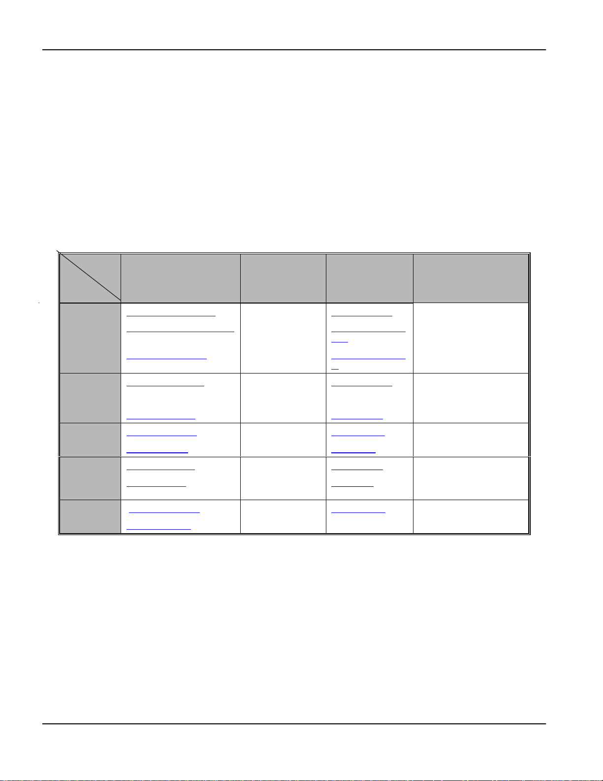
DSL Comparison Chart
Technology Downstream
Rate
IDSL 128 Kbps 128 Kbps 1 Copper
ADSL 256Kbps to
6.1 Mbps
SDSL 144 Kbps to
2320 Kbps
Upstream
Rate
64 Kbps to
512 Kbps
144 Kbps to
2320 Kbps
Wires CO
Pair
1 Copper
Pair
1 Copper
Pair
Chart A DSL Comparison Chart
distance
18,000 feet
18,000 feet
11,500 to
22,000 feet
xx What is DSL?
Page 21

Prestige 1600 Universal Access Concentrator
Chapter 1
Getting to Know Your Concentrator
This chapter describes the key features, benefits and applications of your Prestige.
The Prestige 1600 is a scalable, high-performance, easy-to-configure access concentrator. It consolidates multiple
traffic streams onto a single backbone network. It can be deployed at either the customer’s premise (CP) or a
service provider’s Central Office (CO).
Equipped with one 10/100M Ethernet port, three network module (NM) slots, one WAN interface and one optional
five-port 10M/100M LAN switch card, the architecture of the Prestige 1600 allows network modules of different
generations to coexist in the same chassis and to inter-operate with the same system module.
With its flexible and scalable architecture, you can start with a single P1600 chassis to address low or medium
density network requirements and expand with up to four additional P1600s. With the optional five-port 10/100M
Ethernet switch installed, you can connect up to five units.
1.1 Overview of the Prestige 1600
Physical Dimensions
! Chassis: 17.3" (W) x 13.39" (L) x 2.6" (H); 44cm (W) x 34cm (L) x 6.6cm (H)
! DSL network module: 5.3" (W) x 12.2" (L) x 0.94" (H); 13.5cm (W) x 31cm (L) x 2.4cm (H)
! Rack-mounting options: EIA 19" or 23" front or mid-mount central-office style
Power Requirement
! Built-in 100V-240VAC, 50-60 Hz switching power supply
Operating Environment
! Temperature: 0ºC - 50º C
! Humidity: 20 - 95%
IDSL Interface
! Two 16-port IDSL network modules.
! Up to 160 IDSL ports. 32 IDSL ports in each P1600 chassis.
! IDSL Server only
ADSL Interface
! Three 8-port ADSL network modules.
! Up to 120 ADSL ports (112 if using the 5-port Ethernet switch card). 24 ADSL ports in each P1600
chassis.
SDSL Interface
! Three 8-port SDSL network modules.
! Up to 120 SDSL ports (112 if using the 5-port Ethernet switch card). 24 SDSL ports in each P1600 chassis.
Getting to Know Your Prestige
1-1
Page 22

Prestige 1600 Universal Ac c es s Concentr at or
Network Address Translation (NAT)
NAT (Network Address Translation - NAT, RFC 1631) allows the translation of an Internet Protocol address used
within one network to a different IP address known within another network.
Internet Protocols
! IP routing
! IP packet filtering, including network level and device level filtering
! RIP-1 and RIP-2
! Static IP Route
! MultiNAT for multiple-IP address translation
Ethernet Interface
! Auto-negotiating 10/100M Fast Ethernet port
WAN Interface
! FlexWAN port.
PPP Support
! PPP for WAN connection
Network Management
! Local and remote console management
! SNMP manageable
! Remote secondary management via Telnet using MultiNAT
Security
! CHAP, PAP and RADIUS authentication
Remote Firmware Upgrades
! Console, Telnet, TFTP and FTP Firmware Upgrades
1.2 Key Benefits
! Flexibility, Scalability and High capacity (120 to160 DSL ports with daisy chaining)
! MultiNAT Support
! Mix of DSL types on a single access platform using the existing network infrastructure.
! Reduced network complexity and easy manageability
! Greater bandwidth efficiency
! High speed DSL platform
! Variety of network interfaces and easy upgradability
! Consolidated access to network services over a single carrier
! Cost, space and power efficient solution for Internet access
! SNMP support
1-2
Getting to Know Your Prestige
Page 23

Prestige 1600 Universal Access Concentrator
! Monitoring of WAN/LAN status and port status
! Diagnostics
! Safety tested and high security
1.3 Detailed Features of the Prestige 1600
Modular Architecture
The P1600 chassis is equipped with three network module slots, one system module and two removable fan
modules.
Configuration Types
The Prestige 1600 can be configured via SMT Menu 1 as a primary, secondary or standalone device.
1. Primary
The P1600 primary provides concentration, network management, Internet access and routing functions as well as
uses the FlexWan port as the interface to the trunk.
2. Secondary
The P1600 secondary provides concentration, network management, Internet access and routing functions as well
but only through the LAN interface. A secondary needs to work with a primary device because for WAN access,
you need to connect to a P1600 primary.
3. Standalone
Standalone SMT configurations are the same as a secondary, but in this configuration mode, it does not have to
work with a primary. You can connect a router directly to its LAN port.
Network Interfaces
The P1600 has two trunk interfaces: one Ethernet and one WAN port (primary mode only). The WAN port supports
RS-232, EIA 530,RS-422, X.21 and V.35 interfaces.
Network Protocol Support
The P1600 supports the following network protocols:
! TCP/IP (Transmission Control Protocol/Internet Protocol) network layer protocol.
! IP Policy Routing
! Routing Information Protocol (RIP-1 and RIP-2)
Full Network Management
Your Prestige 1600 offers you a variety of options for network management. It supports password protected local
and remote network management via the console port or a telnet connection. It also supports FTP, TFTP, SNMP
(Simple Network Management Protocol) and CI command.
If you cannot telnet to your Prestige, you can configure your Prestige via a modem connected to the console port
over a phone line as shown in the next figure.
Getting to Know Your Prestige
1-3
Page 24
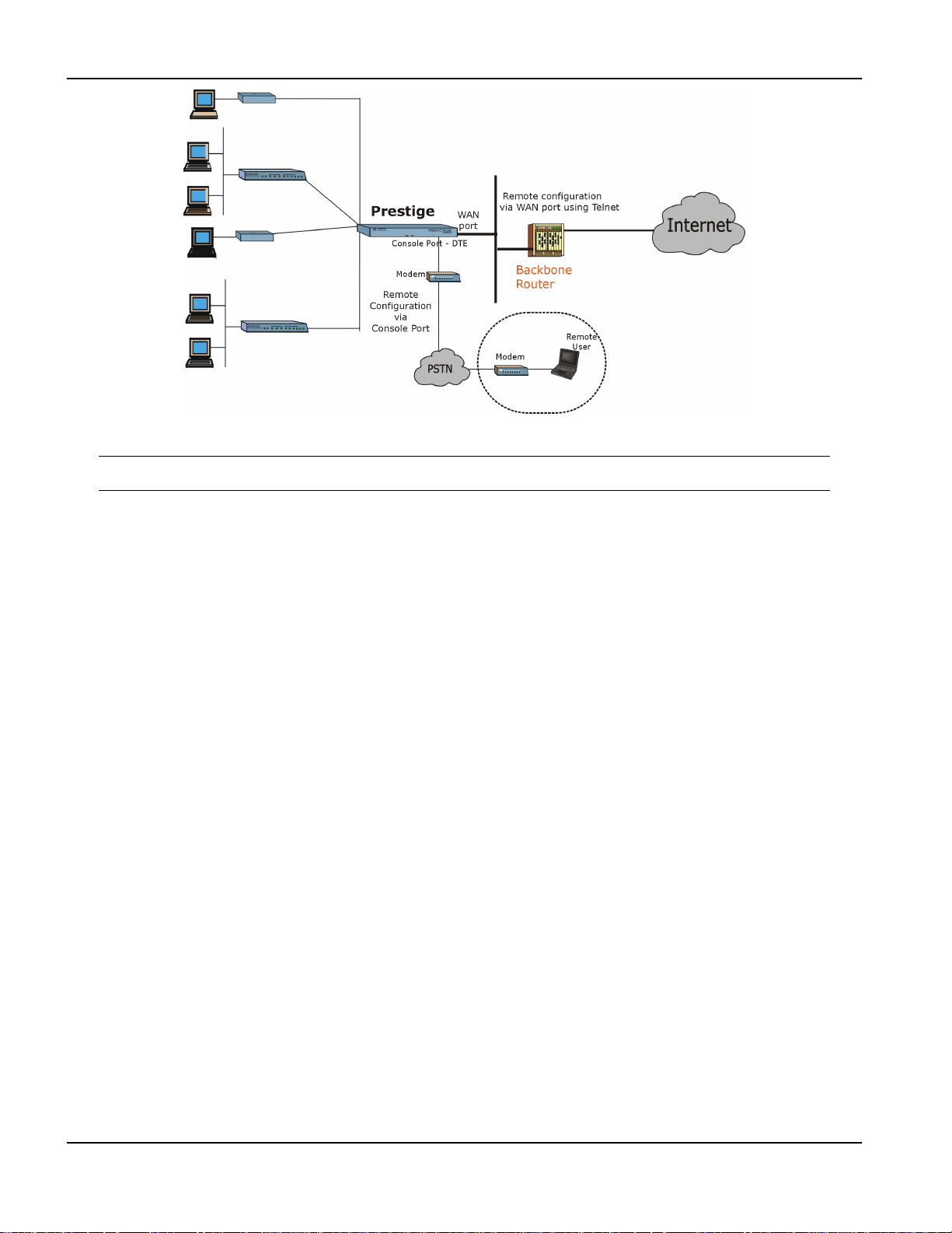
Prestige 1600 Universal Ac c es s Concentr at or
Figure 1-1 Remote Configuration
Please note that for figures in this manual, the “Prestige” refers to the Prestige 1600 and that the
Prestige 1600 clients are not labeled - pl ease see the next section.
Robust Security Features
Your Prestige supports CHAP (Challenge Handshake Authentication Protocol), PAP (Password Authentication
Protocol) and RADIUS (Remote Authentication Dial in User Service). In addition, the SMT is password protected.
You can also configure the LAN, WAN filters to block unwanted incoming and outgoing packets.
Internet Access Sharing
The Prestige 1600 primary support Single User Account (SUA)/Network Address Translation (NAT) which enables
multiple subscribers to access the Internet using a single IP address. The ZyXEL Network Operating System
(ZyNOS) implementation of SUA/NAT allows NetMeeting, CuSeeMe, ICQ and other multimedia application
traffic behind NAT on the client side.
Note that P1600 secondary machine does not support SUA/NAT; only the P1600 primary does on the WAN port.
For a P1600 standalone NAT/SUA is supported over LAN when the Ethernet port is connected to a broadband
modem.
Remote Software Upgrades
The Prestige 1600 uses FLASH memory technology that enables software upgrades without opening the units. The
P1600 can be upgraded via the console port, locally and remotely, as well as via FTP and TFTP.
1-4
Getting to Know Your Prestige
Page 25

Prestige 1600 Universal Access Concentrator
1.4 Prestige 1600 and Prestige DSL Clients
DSL clients suitable for the Prestige 1600 are shown in the following table.
Table 1-1 P1600 DSL Clients
DSL Network Module Prestige Client
Prestige 100LIDSL
Omni 128L
ADSL Prestige 642
SDSL Prestige 681
Please note that for figures in this manual, the word “Prestige” refers to the Prestige 1600 and that the
Prestige 1600 clients are not labeled.
Getting to Know Your Prestige
1-5
Page 26

Page 27
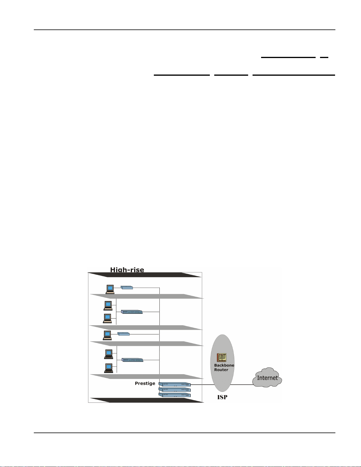
Prestige 1600 Universal Access Concentrator
Chapter 2
Prestige 1600 Applications
This chapter shows you some applications of the Prestige 1600.
2.1 Multi Purpose Concentrator
The Prestige 1600 is a highly flexible, high-speed Internet access solution. It is an integrated, cost-effective solution
for line concentration, routing and network management. Using the existing infrastructure, service providers (ISPs,
Telcos, SIs) and owners of high-rise buildings can take advantage of the DSL technologies using the P1600
concentrator.
2.2 Prestige 1600 Deployment Scenarios
The P1600 concentrator can be deployed at various offices for high-speed Internet Access, campus connectivity and
remote access. It can be deployed at an ISP site or at remote sites (MDU, Telcos/CLECs) with various
configurations. The P1600 provides two kinds of connection to the ISP: WAN port and Ethernet port. When the
P1600 is installed at an ISP site, traffic from the DSL ports is routed to LAN port. When the P1600 is installed at a
remote site, traffic is routed to WAN port, then to an ISP.
The P1600 supports RS-232, EIA 530, RS-422, X.21 and V.35 interface types on the WAN port. The P1600
supports Ethernet port interfaces such as a broadband modem. A few P1600 deployment scenarios are shown next.
2.2.1 Deployed at a High-rise for High-Speed Internet Access
Figure 2-1 Deployed at a High-rise
Property managers or service providers can install the P1600 in Multiple Dwelling Units (MDU) and provide the
subscribers with high-speed Internet access and other services.
Initial Setup
2-1
Page 28
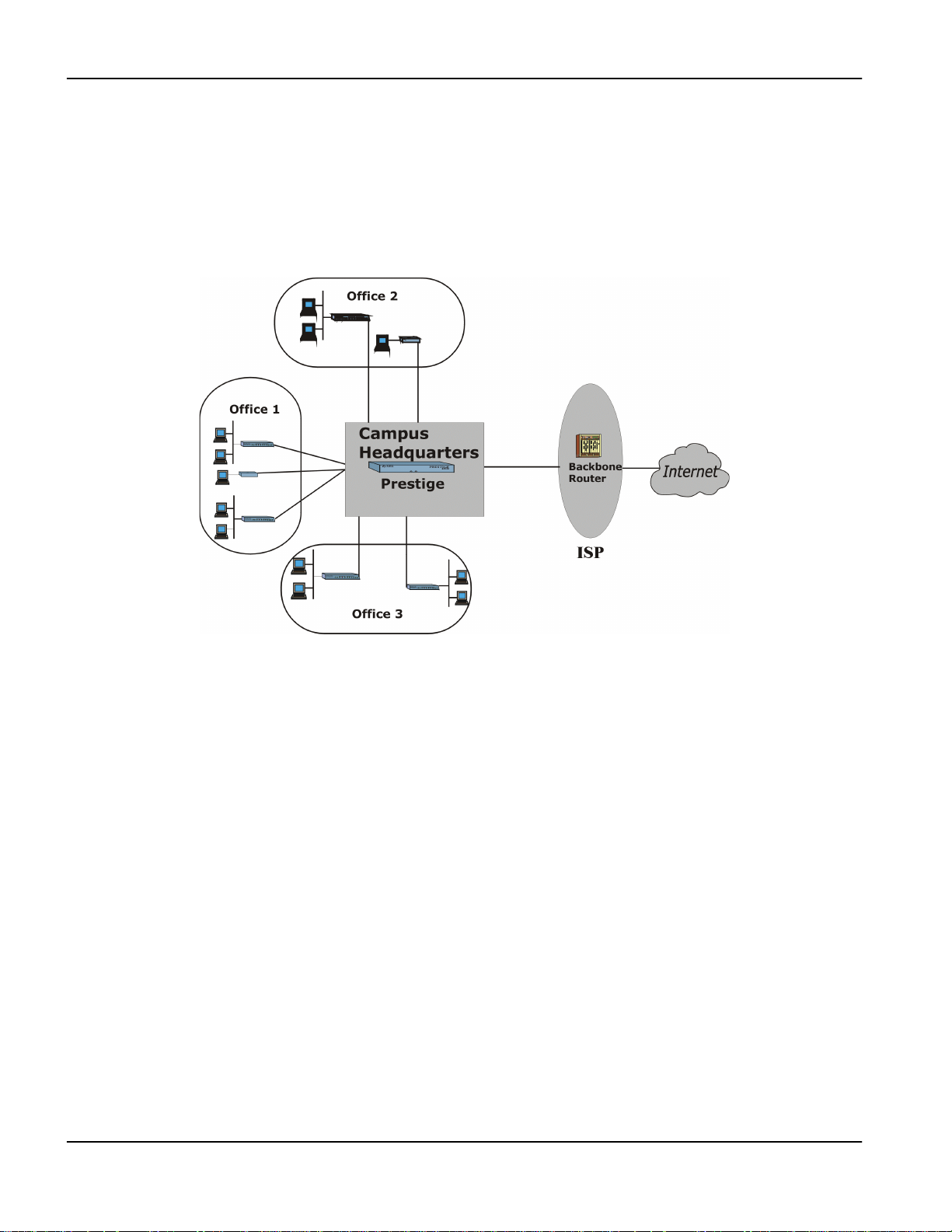
Prestige 1600 Universal Ac c es s Concentr at or
For Internet access with the P1600 in standalone mode, you can connect a broadband device such as a DSL modem
or cable modem to the Ethernet port.
2.2.2 Campus Connectivity
In a campus environment, there are several buildings that need to be interconnected to the computer room. The
P1600 offers a long reach and cost effective solution for universities, corporations, etc. to extend networks to
multiple buildings spread out over large campuses. It can be deployed at a campus for concentration and high-speed
Internet Access, as shown next.
Figure 2-2 Campus Deployment
2.2.3 Deployed at ISPs and Other Service Providers
ISPs and other service providers can offer services to corporate and other customers using the P1600. For example,
the P1600 can be connected to the ISP’s internal LAN and users can access the Internet using the ISP’s router as
shown next.
2-2
Initial Setup
Page 29
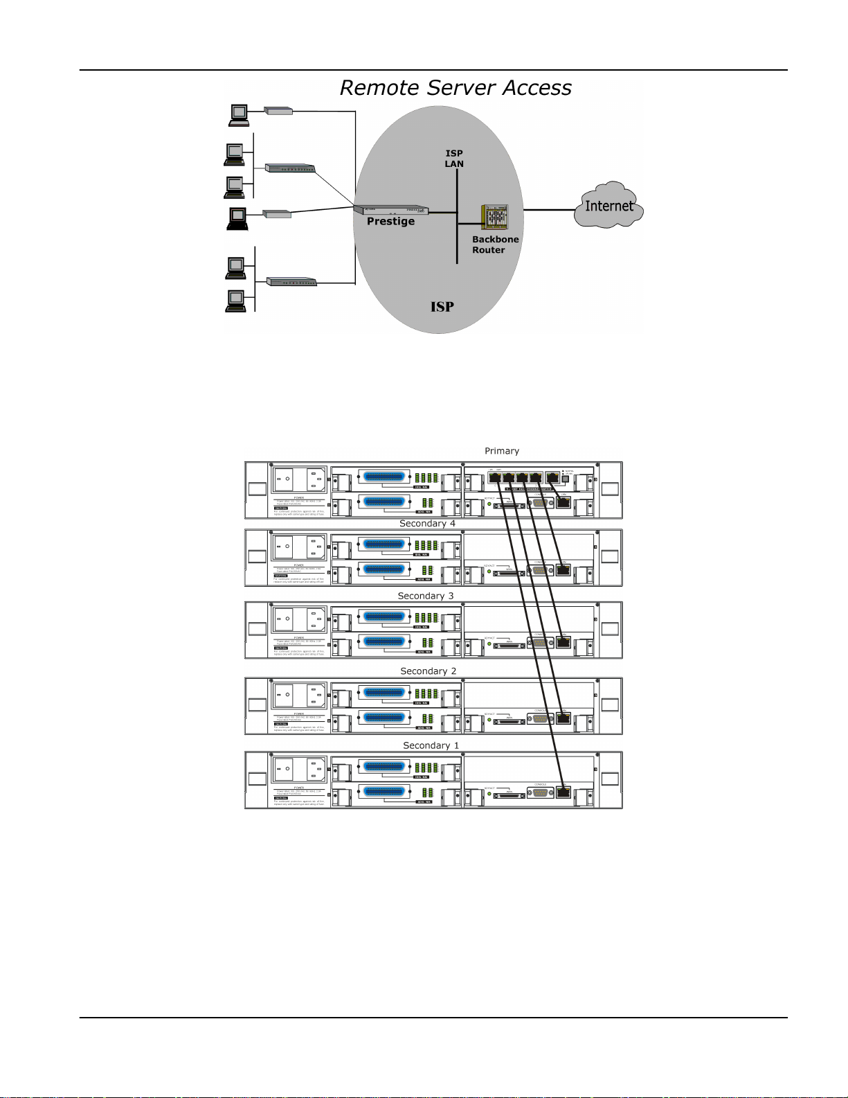
Prestige 1600 Universal Access Concentrator
Figure 2-3 Deployed at an ISP
A few examples of possible configurations for these deployments are shown next.
2.2.4 Configuration Example One
Figure 2-4 A Very High Capacity Concentrator
2.2.5 Configuration Example Two
You can also have any number of P1600 standalones chained to an external Ethernet hub as shown next.
Initial Setup
2-3
Page 30
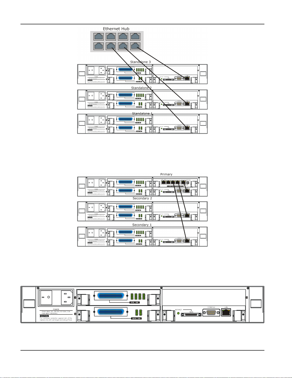
Prestige 1600 Universal Ac c es s Concentr at or
Figure 2-5 High Capacity Concentrator
2.2.6 Configuration Example Three
Depending on your requirement you can vary the number of Prestige 1600 secondaries as shown next.
Figure 2-6 Medium Capacity Concentrator
2.2.7 Configuration Example Four
You can also use the P1600 standalone concentrator for Internet A cces s.
2-4
Figure 2-7 Low Capacity Concentrator
Initial Setup
Page 31

Prestige 1600 Universal Access Concentrator
Chapter 3
Initial Setup
This chapter shows you how to perform initial setup using the SMT.
3.1 Initial Screen
When you power on your Prestige 1600, the router performs several internal tests and initializes the ports. After the
initialization, the Prestige asks you to press [ENTER] to continue, as shown below:
Copyright (c) 2000 ZyXEL Communications Corp.
ethernet address: 00:a0:c5:00:50:02
Press ENTER to continue...
Figure 3-1 Power-On Display
3.1.1 Password
After you press [ENTER], the Login screen appears prompting you to enter the password, as shown in the next
figure.
For your first login, enter the default password 1234. As you enter the password, the screen displays an (X) for
each character you type.
Enter Password : XXXX
Figure 3-2 Login Screen
Please note that if there is no activity for longer than 5 minutes after you log in, your Prestige will automatically log
you out and will display a blank screen. If you see a blank screen, press [ENTER] to bring up the password screen
again.
Initial Setup
3-1
Page 32

Prestige 1600 Universal Ac c es s Concentr at or
3.2 Navigating the SMT Interface
The SMT (System Management Terminal) is the interface that you use to configure your Prestige.
Several operations that you should be familiar with before you attempt to modify the configuration are listed in
Table 3-1.
Table 3-1 Navigating the SMT
Operation Keystrokes Description
Move down to
another menu
Move up to a
previous menu
Move to a
“hidden” menu
Move the cursor [ENTER] or
Enter information Fill in, or press
Required fields
N/A fields <N/A> Some of the fields in the SMT will show a <N/A>. This
Save your
configuration
[ENTER] To move forward to a submenu, type in the number of the
desired submenu and press [ENTER].
[Esc] Press the [Esc] key to move back to the previous menu.
Press the
[SPACE BAR] to
change No to
Yes, then press
[ENTER].
[Up]/[Down] arrow
keys
the [SPACE BAR]
to toggle
?
<
>
[ENTER] Save your configuration by pressing [ENTER] at the
Fields beginning with “Edit” lead to hidden menus and have
a default setting of No. Press the [SPACE BAR] to change
No to Yes, then press [ENTER] to go to a “hidden” menu.
Within a menu, press [ENTER] to move to the next field.
You can also use the [Up]/[Down] arrow keys to move to
the previous and the next field, respecti ve ly.
You need to fill in two types of fields. The first requires you
to type in the appropriate information. The second allows
you to cycle through the available choices by pressing the
[Space] bar.
All fields with the symbol <?> must be filled in order be able
to save the new configuration.
symbol refers to an option that is Not Applicable.
message “Press ENTER to confirm or ESC to cancel”.
Saving the data on the screen will take you, in most cases
to the previous menu.
Exit the SMT Type 99, then
press [ENTER].
Type 99 at the Main Menu prompt and press [ENTER] to
exit the SMT interface.
3.3 SMT Menus At A Glance
The following chart is an overall view of how the SMT menus are organized.
3-2
Initial Setup
Page 33

Prestige 1600 Universal Access Concentrator
Initial Setup
3-3
Page 34

Prestige 1600 Universal Ac c es s Concentr at or
3.3.1 P1600 Main Menu - Primary
The SMT displays a general Main Menu first. Once you configure the system in Menu 1 - General Setup you can
see the P1600 primary Main Menu, as shown next.
Copyright (c) 2000 ZyXEL Communications Corp.
Prestige 1600 Main Menu (MyPrimary)
Getting Started
1. General Setup
2. WAN Setup
3. Ethernet Setup
4. Internet Access Setup
6. Port Setup
Advanced Applications
11. Remote Node Setup
12. Static Routing Setup
15. NAT Setup
Enter Menu Selection Number:
Figure 3-3 Primary Main Menu
The following table shows the Main Menu Summary,
Table 3-2 Main Menu Summary
# Menu Title Description
1 General Setup Use this menu to set up general information and enable routing
or bridging of specific protocols. The name in brackets after
Main Menu is the System Name you assign here.
2 WAN Setup Use this menu to set up the WAN configuration.
Advanced Management
21. Filter Set Configuration
22. SNMP Configuration
23. System Security
24. System Maintenance
25. IP Routing Policy Setup
99. Exit
3-4
3 Ethernet Setup Use this menu to set up the Ethernet configuration.
4 Internet Access Setup A quick and easy way to set up an Internet connection for the
primary 1600.
6 Port Setup Use this menu to configure DSL port parameters and to choose
authentication options.
11 Remote Node Setup Use this menu to set up the remote node for LAN-to-LAN
connections, including an Internet connection for the primary
and standalone models.
12 Static Routing Setup Use this menu to set up static routes for different protocols.
There are eight static routes for each protocol.
15 NAT Setup
Use this menu to co nfigure NA T
.
21 Filter Set Configuration Set up filters to be applied in Menu 3 and Menu 11 to provide
security, call control, etc.
22 SNMP Configuration Use this menu to set up SNMP related parameters
23 System Security Use this menu to set up security related parameters.
24 System Maintenance Provides system status, diagnostics, firmware upload, etc.
25 IP Routing Policy Setup Configure your routing policies here.
Initial Setup
Page 35

Prestige 1600 Universal Access Concentrator
99 Exit To exit the SMT and return to a blank screen.
3.3.2 Secondary and Standalone Main Menu
The SMT Main Menu for the secondary and standalone Prestige models is as shown next.
Copyright (c) 2000 ZyXEL Communications Corp.
Prestige 1600 Main Menu (MySeconda)
Getting Started
1. General Setup
3. Ethernet Setup
6. Port Setup
Advanced Applications
12. Static Routing Setup
15. NAT Setup
Enter Menu Selection Number:
Advanced Management
21. Filter Set Configuration
22. SNMP Configuration
23. System Security
24. System Maintenance
25. IP Routing Policy Setup
99. Exit
Figure 3-4 Secondary and Standalone Main Menu
Note: You will see th e above screen when you set Conf igur atio n Type in Menu 1- General Setup as
secondary or standalone.
3.4 Changing the System Password
The first thing you should do before anything else is to change the default system password by doing the following:
Step 1.
Select option 23 from the Main Menu. This will open Menu 23 - System Security as shown:
Menu 23 - System Security
1. Change Password
2. External Server
Enter Menu Selection Number
Figure 3-5 Menu 23 - System Security
Step 2.
From the System Security Menu, select Change Password to bring up Menu 23.1 - System Security Change Password.
Step 3. When submenu 23.1- System Security-Change Password appears, as shown below, enter the existing
system password, i.e., 1234, then press [ENTER].
Initial Setup
3-5
Page 36

Prestige 1600 Universal Ac c es s Concentr at or
Menu 23.1 - System Security - Change Password
Old Password= XXXX
New Password= XXXX
Retype to confirm= XXXX
Press ENTER to Confirm or ESC to Cancel:
Figure 3-6 Menu 23.1 - System Security - Change Password
Step 4.
Step 5. Re-type your new system password for confirmation and press [ENTER].
Enter your new system password and press [ENTER].
3.5 Resetting the Prestige
If you forget your password or for some reason cannot access the SMT menu, you will need to reload the
configuration file. Uploading the configuration file replace the current configuration file with the new configuration
file. This means that you will lose all configurations that you had before and the speed of the console port will be
reset to the default of 9600bps with 8 data bit, no parity, one stop bit and flow control none. The password will be
reset to 1234, also.
To obtain the default configuration file, download it from the FTP site, unzip it and save it in a folder. Turn off and
then on the Prestige and begin a session. When you turn on the Prestige again you will see the initial screen. When
you see the message “Press any key to enter Debug Mode within 3 seconds” press any key to enter debug mode.
3.6 General Setup
Menu 1 - General Setup contains administrative and system-related information as well as DNS server
information.
3.6.1 DNS Server Address
DNS (Domain Name System) is for mapping a domain name to its corresponding IP address and vice versa, e.g.,
the IP address of www.zyxel.com is 204.217.0.2. The DNS server is extremely important because without it, you
must know the IP address of a machine before you can access it.
Select option 1 from the Main Menu by typing 1 at the menu selection number prompt. If your P1600 is configured
as a primary you will see the following screen. Once you enter the system name it will be displayed in the Main
Menu in brackets.
3-6
Initial Setup
Page 37

Prestige 1600 Universal Access Concentrator
Menu 1 - General Setup
System Name= MyPrimary
Configuration Type= Primary
Secondary ID= N/A
Location=
Contact Person's Name= JohnDoe
Primary DNS Server= 0.0.0.0
Secondary DNS Server= 0.0.0.0
Press ENTER to Confirm or ESC to Cancel:
Figure 3-7 Menu 1 - General Setup (Primary)
When you configure the Prestige as a secondary or standalone model (Configuration Type field), you will see the
following screen.
Menu 1 - General Setup
System Name= MySecondary
Configuration Type= Secondary
Secondary ID= 1
Location=
Contact Person's Name= MaryDoe
Primary DNS Server= 0.0.0.0
Secondary DNS Server= 0.0.0.0
Press ENTER to Confirm or ESC to Cancel:
Figure 3-8 Menu 1 - General Setup (Secondary/Standalone)
The Menu 1 - General Setup fields are explained in the next table.
Table 3-3 General Setup Fields
Field Description Example
System Name Choose a descriptive name for identification purposes. This name
can be up to 30 alphanumeric characters long. Spaces are not
allowed, but dashes “-” and underscores "_" are accepted. This
name can be retrieved remotely via SNMP and will be displayed
up to the first 9 characters at the prompt in the Command Mode.
Note: Once you have configured the System Name, you can see it displayed (up to the first 9
characters) in the Main Menu within brackets next to "Prestige 1600 Main Menu”.
Configuration
Type
Secondary ID
You can configure the P1600 primary as only Primary. For P1600
Secondary choose Secondary or Standalone.
State the ID of the P1600 secondary. You may have up to four
secondaries with one primary.
MyPrimary
Primary
1, 2, 3 or 4
Location
(optional)
Contact
Person's Name
(optional)
Primary DNS
Server
Initial Setup
Enter the geographic location (up to 31 characters) of your
Prestige 1600.
Enter the name (up to 30 characters) of the person in charge of
this Prestige 1600.
Enter the IP addresses of the DNS servers. The DNS servers are passed
to the DHCP clients along with the IP address and the subnet mask.
Hsinchu
JohnDoe
3-7
Page 38

Prestige 1600 Universal Ac c es s Concentr at or
Field Description Example
Leave these entries at 0.0.0.0 if a WAN DHCP server provides them.
Secondary DNS
Server
3-8
Initial Setup
Page 39

Prestige 1600 Universal Access Concentrator
p
Chapter 4
WAN Port Setup
This section describes setting up your WAN port including Frame Relay.
Select option 2 from the Main Menu by typing 2 at the menu selection number prompt. You will see a screen as
shown next.
Menu 2 - WAN Port Setup
Clock Source = External
Port Speed = N/A
Only change the default option
Edit Frame Relay Setup= No
Press Enter to Confirm or ESC to Cancel:
(No) if you wish to configure the
WAN
ort for frame relay.
Figure 4-1 Menu 2 - WAN Port Setup
Table 4-1 WAN Setup Menu Fields
Field Description Example
Clock Source The device connected to the WAN port controls timing. The
P1600 currently only supports an external clock source.
Port Speed Set by External Device
Edit Frame Relay
Setup
To configure the WAN port for frame relay move the cursor
to the Edit Frame Relay Setup= field, press the
[SPACEBAR] once to display Yes and then press
[ENTER]. This takes you to Menu 2.1.2 - Frame Relay
Setup shown ahead.
External
N/A
4.1 Configuring The WAN Port For PPP over HDLC
The following diagram depicts the configuration scenario for running PPP over HDLC (High-level Data Link
Control).
WAN Port Setup
4-1
Page 40

Prestige 1600 Universal Ac c es s Concentr at or
Figure 4-2 Configuring The WAN Port for PPP over HDLC
To run PPP over HDLC directly without frame relay, the Line Type field in Menu 2.1.2 - Frame Relay Setup
must be set to None. To make sure frame relay is disabled, go to menu 2 and then to Menu 2.1.2 – Frame Relay
Setup. If the Line Type field is not None, press [SPACE BAR] to change it before saving the configuration.
4.2 Configuring The WAN Port For Frame Relay
To configure the WAN port for frame relay go to Menu 2 - WAN Port Setup and change the default option (No)
in the Edit Frame Relay Setup field to Yes. Frame relay is a form of packet-switching technology that routes
frames of information from source to destination over a switched network owned by a carrier. Frames are “relayed”
through switches in the network .
Figure 4-3 Configuring The WAN Port For Frame Relay
4.2.1 Standards
The two main groups that create recommendations and standards in the telecommunications field are ITU - T
(International Telecommunication Union - Telecommunications Standardization Sector) and ANSI (American
National Standards Institute). Standards vary slightly for both organizations, so please select the correct standard in
the Link Management field. Your Network Service Provider (NSP) should provide you with this information.
4-2 W
AN Port Setup
Page 41

Prestige 1600 Universal Access Concentrator
4.2.2 How To Configure The WAN Port For Frame Relay
Go to menu 2, then move the cursor to the Edit Frame Relay Setup= field, pre ss the [SPACEBAR] once to
display Yes and then press [ENTER]. This takes you to Menu 2.1.2 - Frame Relay Setup shown next.
Menu 2.1.2 – Frame Relay Setup
Line Type = User
Link Management = ANSI(T1.618)
Press ENTER to Confirm or ESC to Cancel:
Press Space Bar to Toggle.
Figure 4-4 Menu 2.1.2 - Frame Relay Setup
Table 4-2 Menu 2.1.2 - Frame Relay Setup
Field Description Options
Link Type
Link Management Press the [SPACEBAR] and then [ENTER] to
Choose User if the Prestige is on the user side
of the UNI (User Network Interface: defines the
connection between user equipment and the
Frame Relay network), i.e. if your Prestige is
connected to a service provider. Choose None
to disable Frame Relay.
select which standard is compatible with your
Prestige. Both the Prestige and the peer must
use the same standard. The standard defines
functions that are responsible for monitoring the
up/down status and error performance of an
individual link. If failure occurs, recovery actions
are initiated for the restoration of the failed link.
User (default)
None
ITU-T(Q.933)
ANSI(T1.618)
4.3 How To Configure Frame Relay for Internet Access
4.3.1 Encapsulation
Be sure to use the encapsulation method required by your ISP. The Prestige supports the following methods.
RFC 1973 (PPP in Frame Relay)
RFC 1973 describes the use of Frame Relay for transporting PPP encapsulated packets. Please refer to RFC 1973
for more information.
RFC 1490
RFC 1490 describes Multiprotocol Interconnect over Frame Relay encapsulation which is an encapsulation method
for carrying network interconnect traffic (both bridging and routing) over a frame relay network. It also describes a
simple fragmentation procedure for carrying large frames over a frame relay network with a smaller MTU
(Maximum Transmission Unit).
WAN Port Setup
4-3
Page 42

Prestige 1600 Universal Ac c es s Concentr at or
4.3.2 DLCI
The carrier gives you a DLCI (Data Link Connection Identifier) for each frame relay connection to a destination.
Identifiers can range from 1 to 991 with restrictions as shown in the following table. The default DLCI for the first
connection is 16.
Table 4-3 Data Link Connection Identifiers
DLCI Usage
0 Channel Signaling
1-15 Reserved
16 - 991 Frame Relay
4.3.3 CIR (Committed Information Rate)
The carrier programs virtual circuits into the network between your sites and charges you for a specific level of
service called the committed information rate (CIR). The CIR is basically a guarantee that the carrier will always
have that bandwidth available. The CIR limit for the Prestige is 8Mbps. The sum of CIRs from all channels in a line
cannot exceed 8Mbps due to the processing limit of the P1600 CPU.
4.3.4 EIR (Excess Information Rate)
This is the burst capability of the connection, i.e., the maximum allowable data transfer rate. EIR must be greater
than or equal to the CIR.
4.3.5 How To Configure Frame Relay for Internet Access
Go to Menu 4 - Internet Access Setup, move the cursor to the Edit Frame Relay Options= field, press the
[SPACEBAR] once to display Yes and then press [ENTER]. This takes you to Menu 4.2 - Internet Setup Frame
Relay Options shown next.
Menu 4 - Internet Access Setup
ISP's Name= ChangeMe
My Login= 1234
My Password= ********
Network Address Translation= SUA Only
My WAN Addr= 0.0.0.0
Address Mapping Set= N/A
Edit Frame Relay Options= No
Press ENTER to Confirm or ESC to Cancel:
Figure 4-5 Menu 4 - Internet Access Setup
4-4 W
AN Port Setup
Page 43

Prestige 1600 Universal Access Concentrator
Encapsulation= RFC 1490
DLCI = 16
CIR (kbps)= 64
EIR (kbps)= 80
Enter here to CONFIRM or ESC to CANCEL:
Menu 4.2 – Internet Setup Frame Relay Options
Figure 4-6 Menu 4.2 - Internet Setup Frame Relay Options
Table 4-4 Menu 4.2 - Internet Setup Frame Relay Options
Field Description Options/Examples
Encapsulation Be sure to use the encapsulation method
required by your ISP. The Prestige supports the
following methods. See section 4.3.1 for more
information.
DLCI Enter the DLCI number required by your ISP.
This is a path number of a portion of the PVC
(the DLCI changes for each hop through the
network), not the address of the destination.
The default DLCI for the Prestige is 16 for the
first PVC. See section 4.3.2 for more
information.
RFC 1973 (PPP)
RFC 1490
16
CIR (Kbps) Enter the CIR as negotiated with your ISP. See
section 4.3.3 for more information.
EIR (Kbps) Enter the EIR as negot iat ed with your ISP. See
section 4.3.4 for more information.
64
80
4.4 How To Configure Frame Relay For A Remote Node
Configuring Frame Relay for a remote node is similar to configuring Frame Relay for Internet Access.
Go to Menu 11.1 - Remote Node Profile, move the cursor to the move the cursor to the Edi t Frame Relay
Options= field, press the [SPACEBAR] once to display Yes and then press [ENTER]. This takes you to Menu
11.5 - Remote Node Frame Relay Options shown next.
WAN Port Setup
4-5
Page 44

Prestige 1600 Universal Ac c es s Concentr at or
Rem Node Name= verio
Active= Yes
Outgoing:
My Login= scci
My Password= ********
Authen= CHAP/PAP
Press ENTER to CONFIRM or ESC to CANCEL:
Leave name field blank to delete profile
Please enter 0-9, a-z, A-Z, '-', or '_', or leave blank to DELETE profile
Figure 4-7 Menu 11.1 - Remote Node Profile
Menu 11.4 - Remote Node Frame Relay Options
Encapsulation= RFC 1490
DLCI = 16
CIR (kbps)= 64
EIR (kbps)= 80
Menu 11.1 - Remote Node Profile
Edit PPP Options= No
Rem IP Addr= ?
Edit IP = No
Telco Option:
Edit Frame Relay Options= No
Input Filter Sets:
Protocol filters =
Device filters =
Output Filter Sets=
Protocol filters =
Device filters =
Enter here to CONFIRM or ESC to CANCEL:
Figure 4-8 Menu 11.4 - Remote Node Frame Relay Options
The fields in this table are the same as described in Table 4-4 above.
4-6 W
AN Port Setup
Page 45

Prestige 1600 Universal Access Concentrator
Chapter 5
Internet Access
This chapter shows you how to configure the Prestige 1600 primary and Prestige 1600 standalone for
Internet access.
5.1 Introduction
Menu 4 - Internet Access Setup of the SMT allows you to configure the Internet access parameters in a single
screen. For Internet access using the Prestige 1600 standalone you need to only set up a default route using Menu
12 - Static Default Route. While configuring your Prestige for Internet access you have to be careful when setting
the IP addresses to avoid IP conflict. The following section shows the various IP networks in the P1600.
5.1.1 IP Address assignment
Table 5-1 Default DSL IP Address Assignment
Configuration
Type (Menu 1)
Primary 192.168.1.1
Secondary 1 192.168.1.2
P1600 IP
address
Port numbers IP address range assigned to
DSL Clients (Menu 6.1)
IDSL:16 ports 192.168.255.1 ~ 192.1 68.255.16Slot
1
2
Slot
3
1
2
Slot
3
ADSL/SDSL:
8 ports
IDSL:16 ports 192.168.255.17 ~ 192.168.255.32Slot
ADSL/SDSL:
8 ports
IDSL Not Available
ADSL/SDSL:
8 ports
IDSL:16 ports 192.168.254.1 ~ 192.1 68.254.16Slot
ADSL/SDSL:
8 ports
IDSL:16 ports 192.168.254.17 ~ 192.168.254.32Slot
ADSL/SDSL:
8 ports
IDSL Not Available
ADSL/SDSL:
192.268.255.1 ~ 192.168.255 .8
192.168.255.17 ~ 192.168.25 5.2 4
192.168.255.33 ~ 192.168.25 5.4 0
192.268.254.1 ~ 192.168.254 .8
192.168.254.17 ~ 192.168.25 4.2 4
192.168.254.33 ~ 192.168.25 4.4 0
Internet Access
8 ports
IDSL:16 ports 192.168.253.1 ~ 192.1 68.253.16Secondary 2 192.168.1.3 Slot
1
ADSL/SDSL:
8 ports
192.268.253.1 ~ 192.168.253 .8
5-1
Page 46

Prestige 1600 Universal Ac c es s Concentr at or
Configuration
Type (Menu 1)
Secondary 3 192.168.1.4
P1600 IP
address
Port numbers IP address range assigned to
DSL Clients (Menu 6.1)
IDSL:16 ports 192.168.253.17 ~ 192.168.253.32Slot
2
3
1
2
Slot
3
ADSL/SDSL:
8 ports
IDSL Not AvailableSlot
ADSL/SDSL:
8 ports
IDSL:16 ports 192.168.252.1 ~ 192.1 68.252.16Slot
ADSL/SDSL:
8 ports
IDSL:16 ports 192.168.252.17 ~ 192.168.252.32Slot
ADSL/SDSL:
8 ports
IDSL Not Available
ADSL/SDSL:
8 ports
192.168.253.17 ~ 192.168.25 3.2 4
192.168.253.33 ~ 192.168.25 3.4 0
192.268.252.1 ~ 192.168.252 .8
192.168.252.17 ~ 192.168.25 2.2 4
192.168.252.33 ~ 192.168.25 2.4 0
Secondary 4 192.168.1.5
Standalone 192.168.1.1
1
2
Slot
3
1
2
Slot
3
IDSL:16 ports 192.168.251.1 ~ 192.1 68.251.16Slot
ADSL/SDSL:
8 ports
IDSL:16 ports 192.168.251.17 ~ 192.168.251.32Slot
ADSL/SDSL:
8 ports
IDSL Not Available
ADSL/SDSL:
8 ports
IDSL:16 ports 192.168.255.1 ~ 192.1 68.255.16Slot
ADSL/SDSL:
8 ports
IDSL:16 ports 192.168.255.17 ~ 192.168.255.32Slot
ADSL/SDSL:
8 ports
IDSL Not Available
ADSL/SDSL:
192.268.251.1 ~ 192.168.251 .8
192.168.251.17 ~ 192.168.25 1.2 4
192.168.251.33 ~ 192.168.25 1.4 0
192.268.255.1 ~ 192.168.255 .8
192.168.255.17 ~ 192.168.25 5.2 4
192.168.255.33 ~ 192.168.25 5.4 0
8 ports
All DSL users who do not have public IP address can get one private IP address from the Prestige IP address pool
according to the configuration type setup in Menu 1. The default IP addresses for the DSL clients are arranged
sequentially as shown in the table above. A port is identified as e.g., "Primary, Slot 3, port 6" or "Secondary 1, Slot
2, port 4", etc.
5-2 I
nternet Access
Page 47

Prestige 1600 Universal Access Concentrator
5.1.2 Standalone IP Pool
When the Prestige Configuration Type (Menu 1) is set up as Standalone and Internet access is configured
through the Ethernet port, you have to manually enter Ethernet TCP/IP information using Menu 3. There are no
dynamic default IP address assignments in this scenario. The default route has to be configured in Menu 12.
5.2 TCP/IP Parameters
If you wish to know more about TCP/IP, please read on. Or you can skip to 4.3 TCP/IP Ethernet Setup for the
actual configuration.
5.2.1 IP Address and Subnet Mask
Machines on a LAN share one common network number; once you have decided on the network number, pick an
IP address that is easy to remember, e.g., 192.168.1.1, for your Prestige 1600.
The subnet mask specifies the network number portion of an IP address. Your Prestige 1600 will compute the
subnet mask automatically based on the IP address that you entered. You don’t need to change the subnet mask
computed by the Prestige 1600 unless you are instructed to do otherwise.
5.2.2 RIP Setup
RIP (Routing Information Protocol) allows a router to exchange routing information with other routers. The RIP
Direction field controls the sending and receiving of RIP packets. When set to:
1. Both - the Prestige 1600 will broadcast its routing table periodically and incorporate the RIP information that it
receives.
2. In Only - the Prestige will not send any RIP packets but will accept all RIP packets received.
3. Out Only - the Prestige will send out RIP packets but will not accept any RIP packets received.
4. None - the Prestige will not send any RIP packets and will ignore any RIP packets received.
The Version field controls the format and the broadcasting method of the RIP packets that the Prestige 1600 sends
(it recognizes both formats when receiving). RIP-1 is universally supported; but RIP-2 carries more information.
RIP-1 is probably adequate for most networks, unless you have a unusual network topology.
Both RIP-2B and RIP-2M sends the routing data in RIP-2 format; the difference being that RIP-2B uses subnet
broadcasting while RIP-2M uses m ultic as ting .
5.2.3 IP Multicast
Traditionally, IP packets are transmitted in one of either two ways - Unicast (1 sender to 1 recipient) or Broadcast
(1 sender to everybody on the network). IP Multicast is a third way to deliver IP packets to a group of hosts on the
network - not everybody.
IGMP (Internet Group Management Protocol) is a session-layer protocol used to establish membership in a
multicast group - it is not used to carry user data. IGMP version 2 (RFC 2236) is an improvement over version 1
(RFC 1112) but IGMP version 1 is still in wide use. If you would like to read more detailed information about
interoperability between IGMP version 2 and version 1, please see sections 4 and 5 of RFC 2236. The class D IP
address is used to identify host groups and can be in the range 224.0.0.0 to 239.255.255.255. The address 224.0.0.0
is not assigned to any group and is used by IP multicast computers. The address 224.0.0.1 is used for query
messages and is assigned to the permanent group of all IP hosts (including gateways). All hosts must join the
224.0.0.1 group in order to participate in IGMP. The address 224.0.0.2 is assigned to the multicast routers group.
Internet Access
5-3
Page 48

Prestige 1600 Universal Ac c es s Concentr at or
The Prestige supports both IGMP version 1 (IGMP-v1) and IGMP-v2. At start up, the Prestige queries all directly
connected networks to gather group membership. After that, the Prestige periodically updates this information by
sending a membership query to 224.0.0.1. IP Multicasting can be enabled/disabled on the Prestige LAN and/or
WAN interfaces using menus 3.2 (LAN) and 11.3 (WAN). Select None to disable IP Multicasting on these
interfaces.
5.3 IP Policies
Traditionally, routing is based on the destination address only and the router takes the shortest path to forward a
packet. IP Policy Routing (IPPR) provides a mechanism to override the default routing behavior and alter the
packet forwarding based on the policy defined by the network administrator. Policy-based routing is applied to
incoming packets on a per interface basis, prior to the normal routing. Create policies using SMT Menu 25 (see the
IP Policy Routing chapter) and apply them on the Prestige LAN and/or WAN interfaces using menus 3.2 (LAN)
and 11.3 (WAN).
5.4 TCP/IP Ethernet Setup
To edit Menu 3.2, select Menu 3 Ethernet Setup in the Main Menu and then the appropriate LAN. Then select the
submenu option 2, and press [ENTER]. The screen now displays Menu 3.2 - TCP/IP Ethernet Setup as shown
next.
Menu 3.2 - TCP/IP Ethernet Setup
TCP/IP Setup:
IP Address= 192.168.1.1
IP Subnet Mask= 255.255.255.0
RIP Direction= Both
Version= RIP-2B
Multicast= IGMP-v2
IP Policies=
Network Address Translation= N/A
Address Mapping Set= N/A
Enter here to Confirm or ESC to Cancel:
Figure 5-1 Menu 3.2 - TCP/IP Ethernet Setup
Follow Table 5-2 to configure TCP/IP parameters for the Ethernet port.
Table 5-2 TCP/IP Ethernet Setup Menu Fields
Field Description Example
IP Address Enter the IP address of your Prestige 1600 in dotted decimal
notation.
IP Subnet
Mask
RIP
Direction
Your Prestige 1600 automatically calculates the subnet mask
based on the IP address that you assign. Unless you are
implementing subnetting, use the value computed by the
Prestige 1600.
Press [SPACE BAR] to select the RIP direction among
Both/In Only/Out Only/None
192.168.1.1
255.255.255.0
Both
(default)
Version
Multicast
5-4 I
Press [SPACE BAR] to select the RIP version among RIP-
1/RIP-2B/RIP-2M.
Turn on/off IGMP support and select the version from IGMP-
v2/IGMP-v1/None.
RIP-1
(default)
IGMP-v2
nternet Access
Page 49

Prestige 1600 Universal Access Concentrator
Field Description Example
IP Policies You can apply up to four IP Policy sets (from twelve) by
entering their numbers separated by commas, e.g., 3, 4, 6,
11.
Network
Address
Translation
Address
Mapping
Set=
When you have completed this menu, press [ENTER] at the prompt “Press ENTER to
Confirm…” to save your configuration, or press [ESC] at any time to cancel.
Note: When NAT is enabled you can connect the LAN port to any broadband device such
as a cable modem or DSL device. You can also use the LAN port to connect to the ISP’s
internal LAN and access the Internet using the ISP’s router.
Please see the NAT chapter for a more detailed discussion on the
Network Address Translation feature. The choices are Full Feature,
None and SUA Only.
Full Feature
5.5 Collecting Internet Account Information
Before you configure your Prestige 1600 for Internet access, you need to collect your Internet account information
from your ISP. Use Table 5-3 to record your Internet Account Information.
Table 5-3 Internet Account Information
Internet Account Information Write your account information here
IP Address of the ISP's Gateway
Login Name
Password
−
−
−
5.6 Internet Access using the Prestige 1600 Primary
Menu 4 allows you to enter the Internet access parameters in one screen. Menu 4 is actually a simplified setup for
one of the remote nodes that you can access through menu 11. From the Main Menu, enter option 4 to go to Menu
4 - Internet Access Setup, as displayed in the next figure.
Internet Access
5-5
Page 50

Prestige 1600 Universal Ac c es s Concentr at or
Menu 4 - Internet Access Setup
ISP's Name= ChangeMe
My Login= 1234
My Password= ********
Network Address Translation= SUA Only
My WAN Addr= 0.0.0.0
Address Mapping Set= N/A
Edit Frame Relay Options= No
Press ENTER to Confirm or ESC to Cancel:
Figure 5-2 Menu 4 - Internet Access Setup
Table 5-4 contains instructions on how to configure your Prestige 1600 for Internet access.
Table 5-4 Internet Access Setup Menu Fields
Field Description Observation
ISP's Name Enter the name of your Internet Service Provider. (This
information is for identification purposes only.)
My Login
Enter the login name assigned to you by your ISP. (require d)
Name
My Password Enter the password associate d with the log in name
above. Note that this login name/password pair is only for
your Prestige 1600 to connect to the ISP's gateway. For
TCP/IP applications, e.g., FTP, you will need a separate
login name and password for each server.
Network
Address
See the NAT Chapter for more details on this field and
Address Mapping Set below.
Translation
My WAN Addr Some implementations, especially the UNIX derivatives,
require the WAN link to have a separate IP network
number from the LAN and each end must have a unique
address within the WAN network number. If this is the
case, enter the IP address assigned to the WAN port of
your Prestige 1600.
Note that this is the address assigned to your local
Prestige 1600, not the remote router.
Address
See the NAT Chapter
Mapping Set
myISP
(required)
Edit Frame
Relay Options
Please see the WAN Port Setup chapter for a full
discussion of this feature.
Press [ENTER] at the message “Press ENTER to Confirm...” to confirm your configuration,
or press [ESC] at any time to cancel.
5-6 I
nternet Access
Page 51

Prestige 1600 Universal Access Concentrator
Chapter 6
DSL Port Setup
This chapter explains how to edit DSL Port information.
Use Menu 6 to configure the DSL ports. Select 6 from the Main Menu to enter Menu 6 - Slot Selection.
The Prestige automatically detects which network module is inserted in each slot. The following menu appears
when you have 2 ISDL network modules inserted in slots 1 and 2.
Note that ISDL network modules (32 ports per module) may only be inserted in slots 1 and 2 but not
slot 3. ADSL or SDSL network modules (24 ports per module) may be inserted in either slots 1, 2 or 3.
1. Slot 1 Configuration(IDSL NM)
2. Slot 2 Configuration(IDSL NM)
3. Slot 3 Configuration(N/A)
Combinations of network modules are also allowed.
Menu 6 - Slot Selection
Please enter selection:
Figure 6-1 Menu 14 - IDSL Port setup
Choose a slot to configure by entering its index number. The following screen displays an IDSL module in slot 1 of
a Secondary 3 device.
DSL Port Setup
6-1
Page 52

Prestige 1600 Universal Ac c es s Concentr at or
port # Active Type User Name
1. Yes IDSL ________
2. Yes IDSL ________
3. Yes IDSL ________
4. Yes IDSL ________
5. Yes IDSL ________
6. Yes IDSL ________
7. Yes IDSL ________
8. Yes IDSL ________
9. Yes IDSL ________
10. Yes IDSL ________
11. Yes IDSL ________
12. Yes IDSL ________
13. Yes IDSL ________
14. Yes IDSL ________
15. Yes IDSL ________
16. Yes IDSL ________
Enter IDSL Port # to Edit:
Menu 6 - IDSL Port Setup(Secondary 3, Slot 1)
Figure 6-2 DSL Port Setup
Table 6-1 DSL Port Setup Fields
Field Description Option
port # Refers to the DSL port number. The port number range
changes according to the configuration type and network
module type.
Active Indicates whether the DSL port is active or not. You can
configure this in Menu 6.1 Port Usage.
Type Displays the network module type in this slot.
User Name Refers to the name of the user. You can configure this in
Menu 6.1 Port Usage.
Your Prestige displays up to 8 characters in this field and if
you have entered a user name with more than 8 characters
a ‘+’ is appended to the eighth character.
Yes/No
IDSL
ADSL
SDSL
6-2
DSL Port Setup
Page 53

Prestige 1600 Universal Access Concentrator
6.1 Port Usage
Enter a port number to bring up the following menu (for an IDSL module installed).
Menu 6.1 - Port Usage
Active= Yes
Device Type: IDSL
Speed= 128K
Encapsulation= PPP
Authen Method= Local
Protocol= None
User Name=
Password= ********
IP Address Assigned to Client= 192.168.255.1
Start of Public IP Address= 0.0.0.0
IP Count= 0
Multicast= N/A
IP Policies=
Press ENTER to Confirm or ESC to Cancel:
Press Space Bar to Toggle.
Figure 6-3 Menu 6.1 - Port Usage
The following table describes fields in this menu.
Table 6-2 Port Usage Menu Fields
Field Description Option
Active
Device Type The Prestige automatically detects the types of
Speed Press [SPACE BAR] to toggle between speeds.
Encapsulation The Prestige supports PPP encapsulation.
You can disable this port by setting the field to No.
Press [SPACE BAR] to toggle between Yes and No.
This field will be <N/A> if no network module is
installed.
network module installed in the s lot.
Step-through SDSL speeds are in 64 Kbps
increments.
This field will be <N/A> if no network module is
installed.
Yes/No
IDSL ADSL SDSL
64K
128KUpStream
64K
128K
256K
512K
1
PPP
Down
Stream
256K
512K
1M
1.5M
144K
272K
400K
528K
784K
1168K
1552K
2320K
1
RFC 1483 is not supported at the time of writing this manual.
DSL Port Setup
6-3
Page 54

Prestige 1600 Universal Ac c es s Concentr at or
Field Description Option
Authen(ticatio
n) Method
Protocol Press the [SPACE BAR], then [ENTER] to choose
User Name This will be used as the login name for local
Password Enter the password for the remote user. This will be
IP Address
Assigned to
Client
Start of Public
IP Address
IP Count In this field enter the number of addresses in the
This field sets the authentication method for
incoming calls. You can choose Local or RADIUS.
The default for this field is Local. Please see the
next section on User Authentication for more details.
from None, CHAP/PAP, CHAP or PAP. The default
is None.
authentication. You can enter a name with up to 31
characters. This will be N/A when you choose
RADIUS as your authentication method.
N/A when you choose RADIUS as your
authentication method.
Refers to the IP address assigned to the CPE
(Customer Premises Equipment), i.e., the client
device connected to the Prestige.
Refers to the public IP address assigned to the
hosts behind the CPE. The IP range contains
contiguous IP addresses and this field specifies the
first one in the range.
public IP range. For example, if the starting address
is 202.x.x.1 and the IP count is 6, then the pool will
be from 202.x.x.1 to 202.x.x.6.
Local, RADIUS
None, CHAP, PAP, CHAP/PAP
Multicast Turn on/off IGMP support IGMP-v2/IGMP-v1/None.
Please refer to the Multicast section earlier in this
manual for more details about this feature.
IP Policies You can apply up to four IP policy sets (from twelve)
by entering their numbers separated by commas,
e.g., 3, 4, 6, and 11.
IGMP-v1
IGMP-v2
None
6.1.1 Example IDSL Port Setup
In Menu 6.1, the Start of Public IP Address and IP Count fields are for public IP addresses only. If NAT is not
enabled, and the hosts behind the CPE have been assigned public IPs, then you must enter that information here to
enable proper routing.
6-4
DSL Port Setup
Page 55

Prestige 1600 Universal Access Concentrator
Menu 6.1 - Port Usage
Active= Yes
Device Type: IDSL
Speed= 128K
Encapsulation= PPP
Authen Method= Local
Protocol= None
User Name=
Password= ********
IP Address Assigned to Client= 192.168.255.2
Start of Public IP Address= a.95.1.100
IP Count= 6
Multicast= N/A
IP Policies=
Press ENTER to Confirm or ESC to Cancel:
Press Space Bar to Toggle.
Figure 6-4 Example IDSL Port Setup Configuration
Figure 6-5 Example IDSL Port Setup Scenario
In this example, “a” is a number between 0 and 255 and is not acceptable entry for an IP address.
6.1.2 User Authentication
DSL users are authenticated against the DSL user profile in Menu 6 or user information located at the external
RADIUS server. Two options are available: Local and RADIUS.
Table 6-3 DSL User Authentication
Option Action
Local
RADIUS
Use the user name and password entered in
this menu for authentication.
Use the external RADIUS server to
authenticate the user.
6.1.3 PAP/CHAP
Your Prestige supports both Password Authentication Protocol (PAP) and Challenge Handshake Authentication
Protocol (CHAP). CHAP is more secure than PAP becau se the pas sw ord is not sent in cle ar text.
DSL Port Setup
6-5
Page 56

Page 57

Prestige 1600 Universal Access Concentrator
Chapter 7
Remote Node Configuration
This chapter shows you how to configure the profile and TCP/IP parameters of a remote node.
A remote node is required for placing calls to a remote gateway. A remote node represents both the gateway and
the network behind it across a WAN connection. Note that when you use Menu 4 to set up Internet access, you are
actually configuring a remote node.
7.1 Remote Node Setup
Select menu option 11 from the Main Menu to enter Menu11.1 Remote Node Profile as shown next.
Menu 11 - Remote Node Setup
1. ChangeMe (ISP, NAT)
2. ________
3. ________
Enter Node # to Edit:
Figure 7-1 Menu 11 – Remote Node Setup
Enter a remote node index number to bring up the following screen.
Menu 11.1 - Remote Node Profile
Rem Node Name= myISP
Active= Yes
Outgoing:
My Login= scci
My Password= ********
Authen= CHAP/PAP
Press ENTER to CONFIRM or ESC to CANCEL:
Leave name field blank to delete profile
Please enter 0-9, a-z, A-Z, '-', or '_', or leave blank to DELETE profile
Edit PPP Options= No
Rem IP Addr= ?
Edit IP = No
Telco Option:
Edit Frame Relay Options= No
Input Filter Sets:
Protocol filters =
Device filters =
Output Filter Sets=
Protocol filters =
Device filters =
Figure 7-2 Menu 11.1 - Remote Node Profile
Remote Node Configuration
7-1
Page 58

Prestige 1600 Universal Ac c es s Concentr at or
The following table contains the instructions on how to configure the Remote Node Profile Menu for leased lines.
Table 7-1 Remote Node Profile Menu Fields for Leased Lines
Field Description Options
Rem Node Name This is a required field. Enter a descriptive name
for the remote node, e.g., myISP. This field can be
up to eight characters.
Active
Outgoing:
Outgoing:
Outgoing:
Edit PPP Options To edit the PPP options for this remote node,
My Login
Name
My
Password
Authen
Press [SPACE BAR] to toggle between Yes and
No.
Enter the login name for your Prestige 1600 when
it calls this remote node.
Enter the password for your Prestig e 1600 whe n it
calls this remote node.
This field sets the authentication protocol used for
outgoing calls.
Options for this field are:
CHAP/PAP - Your Prestige 1600 will accept either
CHAP or PAP when requested by this remote
node.
CHAP - accept CHAP only. CHAP
PAP - accept PAP only. PAP
move the cursor to this field, press the [SPACE
BAR] to select Yes and press [ENTER]. This will
bring you to Menu 11.2 - Remote Node PPP
Options. For more information on configuring
PPP options, see the section Editing PPP
Options.
Yes/No
CHAP/PAP
(default)
Yes
Rem IP Addr This is a required field. Enter the IP address of the
remote gateway.
Edit IP
Telco Option:
Edit Frame Relay Options Please see the WAN Port Setup chapter for a full
Session Options:
Input Filter Sets, Output
Filter Sets
7-2
To edit the IP parameters, select Yes and press
[ENTER]. This will bring you to Menu 11.3 Remote Node Network Layer Options. For more
information on this screen, refer to the section
Remote Node TCP/IP Configuration.
discussion of this feature.
In these fields, enter the filter set(s) you wish to
apply to the incoming and outgoing traffic between
this remote node and your Prestige 1600. You can
choose from 12 different filter sets. In addition,
you can link up to 4 filter sets together for further
customization, e.g., 1, 5, 9, 12.
Note that spaces are accepted in this field. For
more information on customizing your filter sets,
see Chapter 8. The default is blank, i.e., no filters
Yes
Default =
Blank
Remote Node Configuration
Page 59

Prestige 1600 Universal Access Concentrator
Field Description Options
defined.
Once you have completed filling in Menu 11.1.1 - Remote Node Profile, press [ENTER] at the
message “Press ENTER to Confirm…” to save your configuration, or press [ESC] at any time to
cancel.
7.2 Outgoing Authentication Protocol
Generally speaking, you should employ the strongest authentication protocol possible, for obvious reasons.
However, some vendor’s implementation includes specific authentication protocol in the user profile. It will
disconnect if the negotiated protocol is different from that in the user profile, even when the negotiated protocol is
stronger than specified. If you encounter the case where the peer disconnects right after a successful authentication,
please make sure that you specify the correct authentication protocol when connecting to such an implementation.
Note: Generally, the authentication option is decided by the server hence, for outgoing calls it is not
necessary for you to configure this field except in cases where you are told by the remote server’s
operator.
7.3 Editing PPP Options
To edit the PPP options of a remote node, move the cursor to the Edit PPP Options field in Menu 11.1 - Remote
Node Profile, and press [SPACE BAR] to select Yes. Press [ENTER] to open Menu 11.2, as shown.
Menu 11.2 - Remote Node PPP Options
Compression= No
ENTER here to Confirm or ESC to Cancel:
Press Space Bar to Toggle.
Encapsulation= Standard PPP
Figure 7-3 Menu 11.2 - Remote Node PPP Options
Table 7-2 Remote Node PPP Options Menu Fields describes the Remote Node PPP Options Menu, and contains
instructions on how to configure the PPP options fields.
Remote Node Configuration
7-3
Page 60

Prestige 1600 Universal Ac c es s Concentr at or
Table 7-2 Remote Node PPP Options Menu Fields
Field Description Option
Encapsulation
Select the vendor-specific encapsulation for the link.
The default is Standard PPP. Select Cisco PPP only
when the remote gateway is a Cisco machine.
Standard PPP - Standard PPP encapsulation will be
Standard PPP
used.
CISCO PPP - Cisco PPP encapsulation will be used. CISCO PPP
Compression Turn on/off Stac data compression. The default for this
field is Off.
On/Off
(Default = Off)
Once you have completed filling in Menu 11.2 - Remote Node PPP Options, press
[ENTER] at the message “Press ENTER to Confirm...” to save your configuration, or press
[ESC] at any time to cancel.
7.4 Edit IP Parameters
Move the cursor to the Edit IP field in Menu 11.1 - Remote Node Profile, then press [SPACE BAR] to toggle the
value to Yes, and press [ENTER]
Menu 11.3 Remote Node Network Layer Options
to edit Menu 11.3 - Network Layer Options.
Rem IP Addr= 0.0.0.0
Rem Subnet Mask= 0.0.0.0
My WAN Addr= 0.0.0.0
Network Address Translation= SUA Only
Address Mapping Set= N/A
Metric= 2
Private= No
RIP Direction= None
Version= RIP-1
Multicast= IGMP-v2
IP Policies=
7-4
Enter here to CONFIRM or ESC to CANCEL
Figure 7-4 Menu 11.3- Remote Node TCP/IP Options
Remote Node Configuration
Page 61

Prestige 1600 Universal Access Concentrator
To configure the TCP/IP parameters of a remote node, first configure the two fields in Menu 11 - Remote Node
Profile, as shown.
Table 7-3 TCP/IP related fields in Menu 11.1 - Remote Node Profile
Field Description Option
Rem IP Address Enter the IP address of the remote gateway in
Menu 11.1 Remote Node Profile.
Edit IP
Press [SPACE BAR] to select Yes and press
[ENTER] to go to Menu 11.3 - Remote Node
Network Layer Options.
Yes/No
The following table shows the TCP/IP related fields in Menu 11.3 - Remote Node Network Layer Options.
Table 7-4 Remote Node TCP/IP Configuration
Field Description Option
Rem IP
Address
Rem IP
Subnet Mask
My WAN
Addr
Network
Address
Translation
This shows the IP address you entered for this remote node in
the previous menu, Remote Node Profile.
Enter the subnet mask for the remote network.
Some implementations, especially the UNIX derivatives, require
the WAN link to have a separate IP network number from the
LAN and each end must have a unique address withi n the WAN
network number. If this is the case, enter the IP address
assigned to the WAN port of your Prestige 1600.
Note that this is the address assigned to your local Prestige
1600, not the remote router.
Please see the NAT chapter for a more detailed discussion on
the Network Address Translation feature. The choices are Full
Feature, None and SUA Only.
Full Feature
None and SUA
Only
Address
Mapping
Set= N/A
Metric The metric represents the “cost” of transmission for routing
Private This parameter determines if the Prestige 1600 will include the
RIP
Direction=
Version=
Enter the address mapping set you are applying to this remote
node. 255 is the default (read-only) SUA Only set.
purposes. IP routing uses hop count as the measurement of
cost, with a minimum of 1 for directly connected networks. Enter
a number that approximates the cost for this link. The number
need not be precise, but it must be between 1 and 15. In
practice, 2 or 3 is usually a good number.
route to this remote node in its RIP broadcasts. If set to Yes, this
route is kept private and not included in RIP broadcast. If No,
the route to this remote node will be propagated to other hosts
through RIP broadcasts.
Press [SPACE BAR] to select the RIP direction from Both/In
Only/Out Only/None.
Press [SPACE BAR] to select the RIP version from RIP-1/RIP-
2B/RIP-2M.
Remote Node Configuration
1 to 4, 255
1 to 15
Yes/No
Both/In
Only/Out
Only/None
RIP-1/ RIP-2B/
RIP-2M
7-5
Page 62

Prestige 1600 Universal Ac c es s Concentr at or
Field Description Option
Multicast Turn on/off IGMP support and select the version from IGMP-
v2/IGMP-v1/None.
IP Policies You can apply up to four IP Policy sets (from twelve) by entering
their numbers separated by commas, e.g., 3, 4, 6, 11.
Once you have completed filling in the Network Layer Options Menu, press [ENTER] to return to
Menu 11. Press [ENTER] at the message “Press ENTER to Confirm...” to save your configuration,
or press [ESC] at any time to cancel.
IGMP-v2
IGMP-v2
None
7-6
Remote Node Configuration
Page 63

Prestige 1600 Universal Access Concentrator
Chapter 8
Static Route
This chapter tells you how to configure static routes for the Prestige.
8.1.1 Basics
If you wish to know more about static route basics , please read on. Skip to the Static Route Setup section for the
actual configuration.
Static routes tell a router routing information that it cannot learn automatically through other means. This can arise
in cases where RIP is disabled on the LAN or a remote network is beyond the one that is directly connected to a
remote node.
Each remote node specifies only the network to which the gateway is directly connected, and a router has no
knowledge of the networks beyond. For instance, the Prestige knows about network N2 in the following diagram
through remote node Router 1. However, the Prestige is unable to route a packet to network N3 because it doesn’t
know that there is a route through the same remote node Router 1 (via gateway Router 2). The static routes are for
you to tell the Prestige about the networks beyond the remote nodes.
Figure 8-1 An Example of Static Routing Topology
8.1.2 Static Route Setup
Static routes are required if the DSL client has more than one public IP address. The routing information (static
route) entered in the secondary machine will be passed to the primary machine through RIP. By adding static
routes, the Prestige knows how to route packets belonging to the public IP addresses back to the DSL client’s local
network. The Prestige supports up to 240 static routes. Enter “p” to view a precious page of static routes and “n” to
view the next page.
Static Route
8-1
Page 64

Prestige 1600 Universal Ac c es s Concentr at or
To configure an IP static route, use Menu 12 - IP Static Route Setup, as dis play ed next.
Menu 12 - IP Static Route Setup
No. Name No. Name No. Name No. Name
1. ________ 13. ________ 25. ________ 37. ________
2. ________ 14. ________ 26. ________ 38. ________
3. ________ 15. ________ 27. ________ 39. ________
4. ________ 16. ________ 28. ________ 40. ________
5. ________ 17. ________ 29. ________ 41. ________
6. ________ 18. ________ 30. ________ 42. ________
7. ________ 19. ________ 31. ________ 43. ________
8. ________ 20. ________ 32. ________ 44. ________
9. ________ 21. ________ 33. ________ 45. ________
10. ________ 22. ________ 34. ________ 46. ________
11. ________ 23. ________ 35. ________ 47. ________
12. ________ 24. ________ 36. ________ 48. ________
Enter Selection Number, 'p' for prev OR 'n' for next page:
Figure 8-2 Menu 12 - IP Static Route Setup
8-2
Static Route
Page 65

Prestige 1600 Universal Access Concentrator
Choosing a static route to edit produces the following screen.
Menu 12.1 - Edit IP Static Route
Route #: 1
Route Name= ?
Active= No
Destination IP Address= ?
IP Subnet Mask= ?
Gateway IP Address= ?
Metric= 2
Private= No
Press ENTER to Confirm or ESC to Cancel:
Figure 8-3 Menu 12.1 - Edit IP Static Route
The following table describes the fields for Menu 12.1 - Edit IP Static Route Setup.
Table 8-1 Edit IP Static Route Menu Fields
Field Description Options
Route #
This is the index number of the route as listed in Menu
12 - IP Static Route Setup.
Route Name Enter a descriptive name for this route. This is for
identification purpos e only.
Active This field allows you to activate/deactivate this static
route.
Destination IP
Address
This parameter specifies the IP network address of the
final destination. Routing is always based on network
number. If you need to specify a route to a single host,
use a subnet mask of 255.255.255.255 in the subnet
mask field to force the network number to be identical to
the host ID.
IP Subnet Mask Enter the subnet mask for this destination. Follow the
discussion on IP subnet mask in this chapter.
Gateway IP
Address
Enter the IP address of the gateway. The gateway is an
immediate neighbor of your Prestige that will forward the
packet to the destination. On the LAN the gateway must
be a router on the same segment as your Prestige; over
WAN, the gateway must be the IP address of one of the
remote nodes.
Metric The metric represents the “cost” of transmission for
routing purposes. IP routing uses hop count as the
measurement of cost, with a minimum of 1 for directly
connected networks. Enter a number that approximates
the cost for this link. The number need not be precise,
but it must be between 1 and 15. In practice, 2 or 3 is
usually a good number.
Yes/No
1 to 15
Private This parameter determines if the Prestige 1600 will
Static Route
Yes/No
include the route to this remote node in its RIP
broadcasts. If set to Yes, this route is kept private and
not included in RIP broadcast. If No, the route to this
remote node will be propagated to other hosts through
RIP broadcasts.
8-3
Page 66

Page 67

Prestige 1600 Universal Access Concentrator
Chapter 9
Network Address Translation (NAT)
This chapter discusses how to configure NAT on the Prestige.
9.1 Introduction
NAT (Network Address Translation - NAT, RFC 1631) is the translation of the IP address of a host in a packet,
e.g., the source address of an outgoing packet, used within one network to a different IP address known within
another network.
9.1.1 NAT Definitions
Inside/outside denotes where a host is located relative to the Prestige, e.g., the workstations of your subscribers are
the inside hosts, while the web servers on the Internet are the outside hosts. Global/local denotes the IP address of a
host in a packet as the packet traverses across a router, e.g., the local address refers to the IP address of a host when
the packet is in the local network, while the global address refers to the IP address of the host when the same packet
is travelling in the WAN side. Note that inside/outside refers to the location of a host, while global/local refers to
the IP address of a host used in a packet. Thus, an inside local address (ILA) is the IP address of an inside host in a
packet when the packet is still in the local network, while an inside global address (IGA) is the IP address of the
same inside host when the packet is on the WAN side. The following table summarizes this information.
Term Definition
Inside This refers to the host on the LAN.
Outside This refers to the host on the WAN.
Local This refers to the packet address (source or destination) as the packet travels on the LAN.
Global This refers to the packet address (source or destination) as the packet travels on the WAN.
Please note that the IP address (either local or global) of an outside host is never changed.
9.1.2 What NAT Does
In the simplest form, NAT changes the source IP address in a packet received from a subscriber (the inside local
address) to another (the inside global address) before forwarding the packet to the WAN side. When the response
comes back, NAT translates the destination address (the inside global address) back the inside local address before
forwarding it to the original inside host. Note that the IP address (either local or global) of an outside host is never
changed.
The global IP addresses for the inside hosts can be either static or dynamically assigned by the ISP. In addition, you
can designate servers, e.g., a web server and a telnet server, on your local network and make them accessible to the
outside world. If you do not define any servers (for Many-to-One and Many-to-Many Overload mapping - see
below), NAT offers the additional benefit of firewall protection. If no server is defined in these cases, all incoming
inquiries will be filtered out by your Prestige, thus preventing intruders from probing your network. For more
information on IP address translation, refer to RFC 1631, The IP Network Address Translator (NAT).
NAT
9-1
Page 68

Prestige 1600 Universal Ac c es s Concentr at or
9.1.3 How NAT works
Each packet has two addresses - a source address and a destination address. For outgoing packets, the ILA (Inside
Local Address) is the source address on the LAN, and the IGA (Inside Global Address) is the source address on the
WAN. For incoming packets, the ILA is the destination address on the LAN, and the IGA is the destination address
on the WAN. NAT maps private (local) IP addresses to globally unique ones required for communication with
hosts on other networks. It replaces the original IP source address (and TCP or UDP source port numbers for Manyto-One and Many-to-Many Overload NAT mapping) in each packet and then forwards it to the Internet. The
Prestige keeps track of the original addresses and port numbers so incoming reply packets can have their original
values restored. The following diagram illustrates this.
Figure 9-1 How NAT Works
9.1.4 NAT Mapping Types
NAT supports five types of IP/port mapping. They are:
1. One to One: In One-to-One mode, the Prestige maps one local IP address to one global IP address.
2. Many to One: In Many-to-One mode, the Prestige maps multiple local IP addresses to one global IP address. This is
equivalent to SUA (i.e., PAT, port address translation), ZyXEL’s Single User Account feature.
3. Many to Many Overload: In Many-to-Many Overload mode, the Prestige maps the multiple local IP addresses to shared
global IP addresses.
4. One-to-One (range): In One-to-One (range) mode, the Prestige maps each local IP address to a unique global IP address.
5. Server: This type allows you to specify inside servers of different services behind the NAT to be accessible to the outside
world.
6. No-Change: This NAT mapping t ype allows you to assign global IPs to machines behind NAT.
Port numbers do not change for One-to-One, One-to-One (range) and No-Change NAT mapping types.
The following table summarizes these types.
9-2
NAT
Page 69

Prestige 1600 Universal Access Concentrator
Table 9-1 NAT Mapping Types
Type IP Mapping SMT abbreviation
One-to-One ILA1"# IGA1 1:1
Many-to-One (SUA/PAT) ILA1"# IGA1
ILA2"# IGA1
…
Many-to-Many Overload ILA1"# IGA1
ILA2"# IGA2
ILA3"# IGA1
ILA4"# IGA2
…
One-to-One (range): ILA1"# IGA1
ILA2"# IGA2
ILA3"# IGA3
…
Server Server 1 IP"#
IGA1
Server 2 IP"#
IGA1
Server 3 IP"#
IGA1
M:1
M:M Ov
1-1 Ra
Server
No Change IGA1"# IGA1
IGA2"# IGA2
IGA3"# IGA3
…
No-Ch
9.1.5 SUA (Single User Account) Versus NAT
SUA (Single User Account) in previous ZyNOS versions is a subset of NAT that supports two types of mapping,
Many-to-One and Server. See section 9.2.3 for a detailed description of the NAT set for SUA. The Prestige has
Full Feature NAT support to map local IP addresses to global IP addresses of clients or servers using all mapping
types as outlined in Table 9-1. The Prestige supports NAT sets on a remote node basis. The mapping sets are
reusable, but only one set is allowed for each remote node. Set 255 is for SUA Only which is a convenient, pre-
configured, read only Many-to-1 port mapping set, sufficient for users with just one public IP.
9.2 SMT Menus
9.2.1 Applying NAT in the SMT Menus
You apply NAT via menus 4 or 11.3. The next figure shows you how to apply NAT for Internet access in Menu 4.
Enter 4 from the Main Menu to go to Menu 4 - Internet Access Setup.
NAT
9-3
Page 70

Prestige 1600 Universal Ac c es s Concentr at or
Menu 4 - Internet Access Setup
ISP's Name= ChangeMe
My Login= 1234
My Password= ********
Network Address Translation= SUA Only
My WAN Addr= 0.0.0.0
Address Mapping Set= N/A
Press ENTER to Confirm or ESC to Cancel:
Figure 9-2 Applying NAT for Internet Access
The following figure shows how you apply NAT to the remote node in Menu 11.1.
Step 1. Enter 11 from the Main Menu.
Step 2.
Move the cursor to the Edit IP field, press the [SPACEBAR] to toggle the default No to Yes, then press
[ENTER] to bring up Menu 11.3 - Remote Node Network Layer Options.
Menu 11.3 - Remote Node Network Layer Options
Rem IP Addr: 0.0.0.0
Rem Subnet Mask= 0.0.0.0
My WAN Addr= 0.0.0.0
Network Address Translation= SUA Only
Address Mapping Set= N/A
Metric= 2
Private= No
RIP Direction= None
Version= RIP-1
Multicast= N/A
IP Policies=
Enter here to CONFIRM or ESC to CANCEL:
Figure 9-3 Applying NAT to the Remote Node
The following table describes the options for Network Address Translation.
Table 9-2 Applying NAT in Menus 4 & 11.3
Field Description
Network Address
Translation
Full Feature: You can configure any of the 6 mapping types
described in Tab le 9-1.
9-4
Address Mapping
Set
SUA Only: When you select this option the SMT will use Address
Mapping Set 255 (Menu 15.1 - see section 9.2.3). It is a convenient,
pre-configured, read only Many-to-1 port mapping set, sufficient for
most purposes (especially for users with just one public IP) and
helpful to people already familiar with SUA in previous ZyNOS
versions. Note that there is also a Server type whose IGA is 0.0.0.0
in this set.
None: NAT is disabled when you select this option.
This is the Address Mapping Set that you wish to apply to this node.
Set 255 is reserved for SUA.
NAT
Page 71

Prestige 1600 Universal Access Concentrator
9.2.2 Configuring NAT
To configure NAT, enter 15 from the Main Menu to bring up the following screen.
Menu 15 – NAT Setup
1. Address Mapping Sets
2. Server Set
Enter Menu Selection Number:
Figure 9-4 Menu 15 NAT Setup
9.2.3 Address Mapping Sets and NAT Server Sets:
Use the Address Mapping Sets menus and submenus to create the mapping table for translation. Each remote node
must specify which NAT Address Mapping Set to use. You can only configure set 1 to 4, which supports all
mapping types as outlined in Table 9-1. Set 255 is used for SUA. When you select SUA Only, the SMT will use
the pre-configured Set 255 (read only) - see section 9.1.5.
Enter 1 to bring up Menu 15.1 - Address Mapping Sets.
Menu 15.1 - Address Mapping Sets
1. NAT_SET1
2. NAT_SET2
3. NAT_SET3
4. NAT_SET4
255. SUA (read only)
Figure 9-5 Menu 15.1 Address Mapping Sets
Let’s look first at Option 255 (see section 9.1.5). The fields in this menu cannot be changed. Entering 255 brings up
the following screen.
NAT
9-5
Page 72

Prestige 1600 Universal Ac c es s Concentr at or
Menu 15.1.255 - Address Mapping Rules
Set Name= SUA
Idx Local Start IP Local End IP Global Start IP Global End IP Type
--- --------------- --------------- --------------- --------------- ------
1. 0.0.0.0 255.255.255.255 0.0.0.0 M-1
2. 0.0.0.0 Server
3.
4.
5.
6.
7.
8.
9.
10.
Press ENTER to Confirm or ESC to Cancel:
Figure 9-6 SUA Address Mapping Rules
The following table explains the fields in this screen.
Please note that the fields in this menu are read-only. The Type, Local and Global Start/End IPs are
normally (not for this read-only menu) configured in Menu 15.1.1.1 (described later) and the values
are displayed here.
Table 9-3 SUA Address Mapping Rules
Field Description Options/Example
Set Name This is the name of the set you selected in Menu
15.1 or enter the name of a new set you want to
create.
Idx This is the index or rule number.
Local Start IP
Local End IP
Local Start IP is the starting local IP address (ILA)
(see Figure 9-1). Local End IP is the ending local IP
address (ILA). If the rule is for all local IPs, then the
Start IP is 0.0.0.0 and the End IP is 255.255.255.255.
Global Start
IP
This is the starting global IP address (IGA). If you
have a dynamic IP, enter 0.0.0.0 as the Global Start
IP.
Global End IP This is the ending global IP address (IGA).
Type
These are the mapping types discussed above (see
Table 9-1). Type Server allows you to specify a
server of a given service behind NAT. See section
9.4.3 below for some examples.
Note: For all Local and Global IPs, t he End IP addre s s mus t be numer ic all y gre ate r th an t he IP Star t
address.
SUA
1
0.0.0.0
255.255.255.255
0.0.0.0
N/A
Server
Now let’s look at Option 1 in Menu 15.1. Enter 1 to bring up this menu and look at the differences from the
previous menu. Note that, this screen is not read only, so there are extra Action and Select Rule fields. Note also
that the [?] in the Set Name field means that this is a required field and you must enter a name for the set.
9-6
NAT
Page 73

Prestige 1600 Universal Access Concentrator
Please note that if the Set Name field is left blank, the entire set will be deleted.
Menu 15.1.1 - Address Mapping Rules
Set Name= NAT_SET1
Idx Local Start IP Local End IP Global Start IP Global End IP Type
--- --------------- --------------- --------------- --------------- ------
1.
2
3.
4.
5.
6.
7.
8.
9.
10.
Action= Edit Select Rule=
Press ENTER to Confirm or ESC to Cancel:
Figure 9-7 First Set in Menu 15.1.1
The Type, Local and Global Start/End IPs are configured in Menu 15.1.1.1 (described later) and the
values are displayed here.
9.2.4 Orde ring Your Rules
Ordering your rules is important because the Prestige applies the rules in the order that you specify. When a rule
matches the current packet, the Prestige takes the corresponding action and the remaining rules are ignored. If there
are any empty rules before your new configured rule, your configured rule will be pushed up by that number of
empty rules. For example, if you have already configured rules 1 to 6 in your current set and now you configure
rule number 9. In the set summary screen, the new rule will be rule 7, not 9.
Now if you delete rule 4, rules 5 to 7 will be pushed up by 1 rule, so as old rules 5, 6 and 7 become new rules 4, 5
and 6.
The description of the other fields is as described above. The Type, Local and Global Start/End IPs are configured
in Menu 15.1.1.1 (described later) and the values are displayed here.
Table 9-4 Menu 15.1.1
Field Description Option
Set Name Enter a name for this set of rules. This is a required field.
Please note that if this field is left blank, the entire set will be
deleted.
Action
There are 4 actions. The default is Edit. Edit means you
want to edit a selected rule (see following field). Insert
Before means to insert a rule before the rule selected. The
rules after the selected rule will then be moved down by one
rule. Delete means to delete the selected rule and then all
the indices of the rules after the selected one will be
decremented by 1. Sav e Set means to save the whole set
(note when you choose this action, the Select Rule item will
be disabled).
Edit
Insert Before
Delete
Save Set
NAT
Select Rule
When you choose Edit, Insert Before or Delete in the
previous field the cursor jumps to this field to allow you to
select the rule to apply the action in question.
9-7
Page 74

Prestige 1600 Universal Ac c es s Concentr at or
N.B.: Save Set in the Action field means to save the whole set. You must do this if you make any
changes to the set - including deleting a rule. No changes to the set take place until this action is taken.
Be careful when ordering your rules as each rule is executed in sequence beginning from rule 1.
- Address
Selecting Edit in the Action field and then entering a rule number brings up the following menu, Menu 15.1.1.1
Mapping Rule in which you can edit an individual rule and configure the Type, Local and Global Start/End IPs displayed in
Menu 15.1.1.
Menu 15.1.1.1 Address Mapping Rule
Type= One-to-One
Local IP:
Start=
End = N/A
Global IP:
Start=
End = N/A
Press ENTER to Confirm or ESC to Cancel:
Press Space Bar to Toggle.
Figure 9-8 Editing an Individual Rule in a Set
The following table describes the fields in this screen.
Table 9-5 Menu 15.1.1.1 - configuring an individual rule
Field Description Option/Example
Type Press the [SPACEBAR] to toggle through a total of 6
types. These are the mapping types discussed above
(see Table 9-1). Type Server allows you to specify
multiple servers of different types behind NAT to this
machine. See section 9.4.3 below for some examples.
Local IP Only local IP fields are N/A for server; Global IP fields
MUST be set for Server.
Start This is the starting local IP address (ILA).
End This is the ending local IP address (ILA). If the rule is
for all local IPs, then put the Start IP as 0.0.0.0 and the
End IP as 255.255.255.255. This field is N/A for One-
to-One and Server types.
Global IP
Start This is the starting global IP address (IGA). If you have
a dynamic IP, enter 0.0.0.0 as the Global IP Start. Note
that Global IP Start can be set to 0.0.0.0 only if the
types are Many-to-One or Server.
One-to-One
Many-to-One
Many-to-Many Overload
One-to-One (range)
Server
No Change
0.0.0.0
255.255.255.255
0.0.0.0
9-8
End This is the ending global IP address (IGA). This field is
172.16.23.55
N/A for One-to-One, Many-to-One and Server types.
Note: For all Local and Global IPs, t he End IP addre s s m us t be nume ri call y gr e ate r th an t he Star t IP
address.
NAT
Page 75

Prestige 1600 Universal Access Concentrator
9.3 NAT Server Sets
A NAT server set is a list of inside servers (behind NAT on the LAN) that you can make visible to the outside
world. Menu 15.2 - NAT Server Sets is used to configure these servers.
9.3.1 Multiple Servers behind NAT
If you wish, you can make inside servers for different services, e.g., web or FTP, visible to the outside users, even
though NAT makes your whole inside network appear as a single machine to the outside world. A service is
identified by the port number, e.g., web service is on port 80 and FTP on port 21.
As an example (see the following figure), if you have a web server at 192.168.1.36 and an FTP server 192.168.1.33,
then you need to specify for port 80 (web) the server at IP address 192.168.1.36 and for port 21 (FTP) another at IP
address 192.168.1.33.
Please note that a server machine can support more than one service, e.g., a machine can provide both FTP and
DNS service, while another provides only web service.
Figure 9-9 Multiple Servers Behind NAT
9.3.2 Configuring Inside Servers
Follow the steps below to configure a server behind NAT:
Step 1. Enter 15 in the main menu to go to Menu 15 - NAT Setup.
Step 2.
Step 3.
NAT
Enter 2 to go to Menu 15.2 - NAT Server Sets.
Enter the service port number in the Port # field and the inside IP address of the server in the IP Address
field.
9-9
Page 76

Prestige 1600 Universal Ac c es s Concentr at or
Press [ENTER] at the “Press ENTER to confirm …” prompt to save your configuration after you define all the
servers or press ESC at any time to cancel. The most often used port numbers are shown in the following table.
Please refer to RFC 1700 for further information about port numbers. Please also refer to the included disk for more
examples and details on NAT.
Menu 15.2 - NAT Server Sets
Port #
----
1. (Used by SUA) 0.0.0.0
2.21 192.168.255.1
3.23 192.168. 255.2
4.25 192.168. 255.3
5.80 192.168. 255.4
6. 0 0.0.0.0
7. 0 0.0.0.0
8. 0 0.0.0.0
9. 0 0.0.0.0
10. 0 0.0.0.0
Press ENTER to Confirm or ESC to Cancel:
IP Address
---------------
Figure 9-10 Menu 15.2 - NAT Server Setup
Table 9-6 Common Services & Port numbers
Services Port Number
FTP (File Transfer Protocol) 21
Telnet 23
SMTP (Simple Mail Transfer Protocol) 25
DNS(Domain Name System) 53
HTTP (Hyper Text Transfer protocol or WWW, Web) 80
PPTP (Point-to-Point Tunneling Protocol) 1723
9.4 Examples
9.4.1 Internet Access Only
In this Internet access example, you only need one rule where all the ILAs (Inside Local Addresses) map to one
dynamic IGA (Inside Global Address) assigned by your ISP.
9-10
NAT
Page 77

Prestige 1600 Universal Access Concentrator
Figure 9-11 NAT Example 1
Menu 4 - Internet Access Setup
ISP's Name= EG1
My Login= 1234
My Password= ********
Network Address Translation= SUA Only
My IP Addr= 0.0.0.0
Address Mapping Set= N/A
Press ENTER to Confirm or ESC to Cancel:
Figure 9-12 NAT Example for Internet Access
In Menu 4 choose the SUA Only option for the Network Address Translation field. This is a pre-config ur ed
Many-to-One mapping discussed in section 9.1.4.
9.4.2 Example 2 - Internet Access with a Default Inside Server
Figure 9-13 NAT Example 2
In this case, you do exactly as above (use the convenient pre-configured SUA Only set) and also go to Menu 15.2
to specify the inside server behind the NAT as shown in the next figure. All incoming connections are forwarded to
the default inside server at the IP address specified.
NAT
9-11
Page 78

Prestige 1600 Universal Ac c es s Concentr at or
Menu 15.2 - NAT Server Sets
Port #
----
1. (Used by SUA) 192.168.1.10
2. 0 0.0.0.0
3. 0 0.0.0.0
4. 0 0.0.0.0
5. 0 0.0.0.0
6. 0 0.0.0.0
7. 0 0.0.0.0
8. 0 0.0.0.0
9. 0 0.0.0.0
10. 0 0.0.0.0
Press ENTER to Confirm or ESC to Cancel:
Figure 9-14 Specifying an Inside Sever
9.4.3 Example 3 - General Case
IP Address
---------------
In this example, there are 3 IGAs from your ISP. There are many departments but two have their own FTP server.
All departments share the same router. You want to reserve 1 IGA for each department with an FTP server and the
other IGA is used by all. You want to map the FTP servers to the first two IGAs and the other LAN traffic to the
remaining IGA. You also want to map the third IGA to an inside web server and mail server. You need to configure
4 rules as follows.
Rule 1. You map the first IGA to the first inside FTP server (1: 1 mapping, giving both local and global IP
addresses).
Rule 2. You map the second IGA to the second inside FTP server (1: 1 mapping, giving both local and global IP
addresses).
Rule 3.
Rule 4.
You map all other addresses to IGA3 (Many : 1 mapping).
You also use the third IGA to open the web server and mail server on the LAN. Type Server allows us
to specify a server, of a given service behind NAT.
The situation looks somewhat like this:
9-12
Figure 9-15 NAT - Example 3
NAT
Page 79

Prestige 1600 Universal Access Concentrator
Step 1. You need to configure Address Mapping Set 1 from Menu 15.1 - Address Mapping Sets. Therefore you
must choose the Full Feature opt ion from the Network Address Translation field (in Menu 4 or Menu
11.3).
Step 2.
Step 3.
Enter 15 from the Main Menu.
Enter 1 to configure the Address Mapping Sets.
Step 4. Choose 1 to begin configuring this new set. Enter a Set Name, choose the Edit Action and then select 1
from Select Rule field. Press [ENTER] to confirm.
Step 5. Select Type= as One-to-One and enter the local St art IP as 192.168.1.10 (the IP address of FTP Server
1), the global Start IP as 10.132.50.1 (the first IGA). (See Figure 9-16)
Step 6. Repeat the previous step for rules 2 to 4 as outlined above.
Step 7.
When finished, Menu 15.1.1 should look like as shown in Figure 9-17.
The following figure shows how to configure the first rule.
Menu 15.1.1.1 Address Mapping Rule
Type= One-to-One
Local IP:
Start= 192.168.1.10
End = N/A
Global IP:
Start= 10.132.50.1
End = N/A
Press ENTER to Confirm or ESC to Cancel:
Figure 9-16 Example 3 - Menu 15.1.1.1
When you have configured all four rules, Menu 15.1.1 should look as follows.
Menu 15.1.1 - Address Mapping Rules
Set Name= Example3
Idx Local Start IP Local End IP Global Start IP Global End IP Type
--- --------------- --------------- --------------- --------------- ------
1. 192.168.1.10 10.132.50.1 1-1
2 192.168.1.11 10.132.50.2 1-1
3. 0.0.0.0 255.255.255.255 10.132.50.3 M-1
4. 10.132.50.3 Server
5.
6.
7.
8.
9.
10.
Action= Edit Select Rule=
Press ENTER to Confirm or ESC to Cancel:
Figure 9-17 Example 3 Final Menu 15.1.1
Now you configure IGA3 to map to the web and mail server on the LAN.
Step 8. Enter 15 from the Main Menu.
NAT
9-13
Page 80

Prestige 1600 Universal Ac c es s Concentr at or
Step 9. Enter 2 from this menu and configure it as shown in Figure 9-18.
Menu 15.2 - NAT Server Sets
Port #
----
1. (Used by SUA) 0.0.0.0
2.80 192.168.1.21
3. 25 192.168.1.20
4. 0 0.0.0.0
5. 0 0.0.0.0
6. 0 0.0.0.0
7. 0 0.0.0.0
8. 0 0.0.0.0
9. 0 0.0.0.0
10. 0 0.0.0.0
Press ENTER to Confirm or ESC to Cancel:
IP Address
---------------
Figure 9-18 Example 3 - Menu 15.2
9.4.4 NAT Unfriendly Application Programs
Many applications, e.g., gaming programs are NAT unfriendly because they embed addressing information in the
data stream. In this case it is better to use the No Change NAT mapping type for computers running such
applications behind NAT.
9.4.5 Example 4 - Remote Management
You can remotely manage a secondary P1600 behind NAT on the primary. Please see the Remote Management
chapter.
9.4.6 Applying NAT to the Ethernet Port
You can also apply NAT to the Ethernet port if the Configuration Type in Menu 1 is Standalone. This feature is
useful when you connect a broadband device such as a DSL modem or cable modem via the Ethernet port. NAT in
Menu 3.2 applies solely to the Ethernet port.
9-14
NAT
Page 81

Prestige 1600 Universal Access Concentrator
Figure 9-19 Ethernet SUA
Menu 3.2 - TCP/IP Setup
TCP/IP Setup:
IP Address= 192.168.1.1
IP Subnet Mask= 255.255.255.0
RIP Direction= Both
Version= RIP-2B
Multicast= N/A
IP Policies=
Network Address Translation= Full Feature
Address Mapping Set= 2
Press ENTER to Confirm or ESC to Cancel:
Figure 9-20 Applying NAT on the LAN Port
To use the Ethernet port for Internet Access, go to Menu 12 - IP Static Route Setup to set up the static default
route using a P1600 standalone. Please refer to the chapter on Remote Node Configuration for more details.
NAT
9-15
Page 82

Page 83

Prestige 1600 Universal Access Concentrator
Chapter 10
Filter Configuration
This chapter shows you how to create and apply filter(s).
10.1 About Filtering
Your Prestige uses filters to decide whether to allow passage of a data packet and/or to make a call. There are two
types of filter applications: data filtering and call filtering. Filters are subdivided into device and protocol filters,
which are discussed later.
Data filtering screens the data to determine if the packet should be allowed to pass. Data filters are divided into
incoming and outgoing filters, depending on the direction of the packet relative to a port. Data filtering can be
applied on either the WAN side or the LAN side. Call filtering is used to determine if a packet should be allowed to
trigger a call. Outgoing packets must undergo data filtering before they encounter call filtering as shown in the
following figure.
Call Filtering
Outgoing
Packet
No
Data
Filtering
Drop
packet
match
Match MatchMatch
Call Filters
Drop packet
if line not up
Built-in
default
No
match
Or Or
Send packet
but do not reset
Idle Timer
User-defined
Call Filters
(if applicable)
Drop packet
if line not up
Send packet
but do not reset
Idle Timer
No
match
Active Data
Initiate call
if line not up
Send packet
and reset
Idle Timer
Figure 10-1 Outgoing Packet Filtering Process
The following sections describe how to configure filter sets. Please see the application notes for more information
and examples on creating and configuring filters.
10.2 The Filter Structure of the Prestige
A filter set consists of one or more filter rules. Usually, you would group related rules, e.g., all the rules for
NetBIOS, into a single set and give it a descriptive name. The Prestige allows you to configure up to twelve filter
sets with six rules in each set, for a total of 72 filter rules in the system.
You can apply up to four filter sets to a particular port to block multiple types of packets. With each filter set
having up to six rules, you can have a maximum of 24 rules active for a single port.
The following diagram illustrates the logic flow when executing a filter rule.
Filter Configuration
10-1
Page 84

Prestige 1600 Universal Ac c es s Concentr at or
Start
Packet into
filter
Fetch First
Filter Set
Filter Set
Fetch Next
Filter Set
Yes
Next Filter Set
Available?
No
No
Fetch Next
Filter Rule
Yes
Next filter
Rule
Available?
Check
Next
Rule
Fetch First
Filter Rule
No
Active?
Execute
Filter Rule
Drop
Yes
Forward
Accept PacketDrop Packet
Figure 10-2 Filter Rule Process
10-2
Filter Configuration
Page 85

Prestige 1600 Universal Access Concentrator
10.3 Configuring a Filter Set
To configure a filter sets, follow the procedure below:
Step 1. Enter 21 from the Main Menu to open Menu 21 - Filter Set Configuration.
Menu 21 - Filter Set Configuration
Filter
Set #
-----1
2
3
4
5
6
Enter Filter Set Number to Configure=
Edit Comments=
Press ENTER to Confirm or ESC to Cancel:
Comments
-----------------______________
______________
______________
______________
______________
______________
Figure 10-3 Menu 21 - Filter Set Configuration
Filter
Set #
-----7
8
9
10
11
12
Comments
-----------------______________
______________
______________
______________
______________
______________
Step 2.
Step 3.
Step 4.
Enter the index of the filter set you wish to configure (no. 1-12) and press [ENTER].
Enter a descriptive name or comment in the Edit Comments field and press [ENTER].
Press [ENTER] at the message “Press ENTER to confirm” to open Menu 21.1 - Filter Rules Summary.
Filter Configuration
10-3
Page 86

Prestige 1600 Universal Ac c es s Concentr at or
Menu 21.1 - Filter Rules Summary
# A Type Filter Rules M m n
- - ---- -------------------------------------------- ------ - - 1 Y IP Pr=6, SA=0.0.0.0, DA=0.0.0.0, DP=137 N D N
2 Y IP Pr=6, SA=0.0.0.0, DA=0.0.0.0, DP=138 N D N
3 Y IP Pr=6, SA=0.0.0.0, DA=0.0.0.0, DP=139 N D N
4 Y IP Pr=17, SA=0.0.0.0, DA=0.0.0.0, DP=137 N D N
5 Y IP Pr=17, SA=0.0.0.0, DA=0.0.0.0, DP=138 N D N
6 Y IP Pr=17, SA=0.0.0.0, DA=0.0.0.0, DP=139 N D F
Enter Filter Rule Number (1-6) to Configure: 1
Edit Comments= NetBIOS_WAN
Press ENTER to Confirm or ESC to Cancel:
Enter Filter Rule Number (1-6) to Configure:
Figure 10-4 Menu 21.1 - Filter Rules Summary
10.3.1 Filter Rules Summary Menu
These screens show a summary of the existing rules in an example filter set. The following tables contain a brief
description of the abbreviations used in Menu 21.1 and Menu 21.2.
Table 10-1 Abbreviations Used in the Filter Rules Summary Menu
Abbreviations Description Display
# Refers to the filter rule number (1-6).
A Refers to Active. [Y] means the filter rule is
active.
[N] means the filter rule is
inactive.
Type Refers to the type of filter rule.
This shows IP for TCP/IP, and Device
Filter Rules The filter rule parameters are
displayed here (see below).
M Refers to More.
[Y] means an action can not yet be
taken as there are more rules to check,
which are concatenated with the
present rule to form a rule chain.
When the rule chain is complete an
action can be taken.
[N] means you can now specify an
action to be taken i.e., forward the
packet, drop the packet or check the
next rule. For the latter, the next rule is
independent of the rule just checked.
[IP] for TCP/IP
[Dev] for Device
[Y] means there are more
rules to check.
[N] means there are no more
rules to check.
If More is Yes, then Action Matched
and Action Not Matched will be N/A.
m Refers to Action Matched. [F] means to forward the
10-4
Filter Configuration
Page 87

Prestige 1600 Universal Access Concentrator
Abbreviations Description Display
[F] means to forward the packet
immediately and skip checking the
remaining rules if any.
packet.
[D] means to drop the
packet.
[N] means check the next
rule.
n Refers to Action Not Matched
[F] means to forward the packet
immediately and skip checking the
remaining rules if any.
[F] means to forward the
packet.
[D] means to drop the
packet.
[N] means check the next
rule.
The protocol dependent filter rules abbr ev iat ion are li ste d as follows:
If the filter type is IP, the following abbreviations listed in the following table will be used.
Table 10-2 Abbreviations Used If Filter Type Is IP
Abbreviation Description
Pr Protocol
SA Source Address
SP Source Port number
DA Destin ati on Addres s
DP Destin ati on Port number
If the filter type is Dev (device), the following abbreviations listed in the following table will be used.
Table 10-3 Abbreviations Used If Filter Type Is Dev
Abbreviation Description
Off Offset
Len Length
Refer to the next section for information on conf ig uring the filt er rul es.
10.4 Configuring a Filter Rule
To configure a filter rule, enter its num ber in Menu 21.1 - Filter Rules Summary and press [ENTER] to open
Menu 21.1.1 for the rule.
10.5 Filter Types and NAT
There are two classes of filter rules, Generic Filter (Device) rules and Protocol Filter (TCP/IP) rules. Generic
Filter rules act on the raw data from/to LAN and WAN. Protocol Filter rules act on the IP packets. Generic and
TCP/IP filter rules are discussed in more detail in the next section. When NAT (Network Address Translation) is
Filter Configuration
10-5
Page 88

Prestige 1600 Universal Ac c es s Concentr at or
enabled, the inside IP address and port number are replaced on a connection-by-connection basis, which makes it
impossible to know the exact address and port on the wire. Therefore, the Prestige applies the protocol filters to the
“native” IP address and port number before NAT for outgoing packets and after NAT for incoming packets. On the
other hand, the generic, or device filters are applied to the raw packets that appear on the wire. They are applied at
the point when the Prestige is receiving and sending the packets; i.e. the interface. The interface can be an Ethernet
port or any other hardware port. The following diagram illustrates this.
Figure 10-5 Protocol and Device Filter Sets
To speed up filtering, all rules in a filter set must be of the same type, i.e., Protocol filters or Device filters. The
class of a filter set is determined by the first rule that you create. When applying the filter sets to a port, separate
menu fields are provided for protocol and device filter sets. If you include a protocol filter set in a device filters
field or vice versa, the Prestige will warn you and will not allow you to save.
10.5.1 TCP/IP Filter Rule
This section shows you how to configure a TCP/IP filter rule. TCP/IP rules allow you to base the rule on the fields
in the IP and the upper layer protocol, e.g., UDP and TCP, headers.
To configure a TCP/IP rules, select TCP/IP Filter Rule from the Filter Type field and press Enter to open Menu
21.1.1 - TCP/IP Filter Rule, as shown next.
10-6
Filter Configuration
Page 89

Prestige 1600 Universal Access Concentrator
Menu 21.1.1 - TCP/IP Filter Rule
Filter #: 1,1
Filter Type= TCP/IP Filter Rule
Active= Yes
IP Protocol= 6 IP Source Route= No
Destination: IP Addr= 0.0.0.0
IP Mask= 0.0.0.0
Port #= 137
Port # Comp= Equal
Source: IP Addr= 0.0.0.0
IP Mask= 0.0.0.0
Port #= 0
Port # Comp= None
TCP Estab= No
More= No Log= None
Action Matched= Check Next Rule
Action Not Matched= Check Next Rule
Press ENTER to Confirm or ESC to Cancel:
Press Space Bar to Toggle.
Figure 10-6 Menu 21.1.1 - TCP/IP Filter Rule
The following table describes how to configure your TCP/IP filter rule.
Table 10-4 TCP/IP Filter Rule Menu Fields
Field Description Option
Filter # This is the filter set, filter rule co-ordinates, i.e.,
2,3 refers to the second filter set and the third filter
rule of that set.
Filter Type Press [SPACE BAR] to toggle between types of
rules. Parameters displayed below each type will
be different.
Active This field activates/deactivates the filter rule.
IP Protocol Protocol refers to the upper layer protocol, e.g.,
TCP is 6, UDP is 17 and ICMP is 1. This value
must be between 0 and 255. Enter 0 if IP protocol
is don’t care.
IP Source
Route
Destination: IP
Addr
Destination: IP
Mask
If Yes, the rule applies to packet with IP source
route option; else the packet must not have
source route option. The majority of IP packets
do not have source route.
Enter the destination IP Address of the packet you
wish to filter. This field is a ignored if it is 0.0.0.0.
Enter the IP subnet mask to apply to the
Destination: IP Addr. To filter a single host, enter
255.255.255.255 as the mask.
Device Filter
Rule / TCP/IP
Filter Rule
Yes/No
0-255
Yes/No
Destination:
Port #
Destination:
Port # Comp
Filter Configuration
Enter the destination port of the packets that you
wish to filter. The range of this field is 0 to 65535.
This field is ignored if it is 0.
Select the comparison to apply to the destination
port in the packet against the value given in
0-65535
None/Less/Grea
ter/Equal/Not
10-7
Page 90

Prestige 1600 Universal Ac c es s Concentr at or
Field Description Option
Destination: Port #.
Equal
Source: IP
Addr
Source: IP
Mask
Source: Port # Enter the source port of the pack ets that you wish
Source: Port #
Comp
TCP Estab This field is applicable only when IP Protocol field
More
Log Select the logging option from the following:
Enter the source IP Address of the packet you
wish to filter. This field is a ignored if it is 0.0.0.0.
Enter the IP subnet mask to apply to the Source:
IP Addr.
to filter. The range of this field is 0 to 65535. This
field is a ignored if it is 0.
Select the comparison to apply to the source port
in the packet against the value given in Source:
Port #.
is 6, TCP. If Yes, the rule matches only
established TCP connections; else the rule
matches all TCP packets.
If Yes, a matching packet is passed to the next
filter rule before an action is taken; else the packet
is disposed of according to the action fields.
If More is Yes, then Action Matched and Action
Not Matched will be N/A.
None - No packets will be logged.
0-65535
None/Less/Grea
ter/Equal/Not
Equal
Yes/No
Yes/N/A
None
Action Matched
Action Matched - Only packets that match the
rule parameters will be logged.
Action Not Matched - Only packets that do not
match the rule parameters will be logged.
Both - All packets will be logged.
Action Matched Select the action for a matching packet.
Action Not
Matched
Once you have completed filling in Menu 21.1.1 - TCP/IP Filter Rule, press [ENTER] at
the message “Press ENTER to Confirm” to save your configuration, or press [ESC] to
cancel. This data will now be displayed on Menu 21.1 - Filter Rules Summary.
Select the action for a packet not matching the
rule.
The next diagram illustrates the logic flow of an IP filter.
Action Not
Matched
Both
Check Next Rule
Forward
Drop
Check Next Rule
Forward
Drop
10-8
Filter Configuration
Page 91

Packet
into IP Filter
Prestige 1600 Universal Access Concentrator
Filter Active?
Yes
Apply SrcAddrMask
to Src Addr
Check Src
IP Addr
Matched
Apply DestAddrMask
to Dest Addr
Check Dest
IP Addr
Matched
Check
IP Protocol
Matched
Check Src &
Dest Port
Matched
More?
No
Not Matched
Not Matched
Not Matched
Not Matched
Yes
No
Action Matched
Drop
Drop Packet Accept Packet
Check Next Rule
Forward
Check Next Rule
Check Next Rule
Action Not Matched
Drop Forward
Figure 10-7 Executing an IP Filter
10.5.2 Device Filter Rule
This section shows you how to configure a device filter rule. The purpose of device rules is to allow you to filter
non-IP/IPX packets. For IP and IPX, it is generally easier to use the protocol rules directly.
For Device rules, the Prestige treats a packet as a byte stream as opposed to an IP or IPX packet. You specify the
portion of the packet to check with the Offset (from 0) and the Length fields, both in bytes. The Prestige applies
the Mask (bit-wise ANDing) to the data portion before comparing the result against the Value to determine a match.
The Mask and Value are specified in hexadecimal numbers. Note that it takes two hexadecimal digits to represent a
byte, so if the length is 4, the value in either field will take 8 digits, e.g., FFFFFFFF.
To configure a device rule, select Device Filter Rule in the Filter Type field and press [ENTER] to open Menu
21.1.1 - Device Filter Rule, as shown below.
Filter Configuration
10-9
Page 92

Prestige 1600 Universal Ac c es s Concentr at or
Menu 21.1.1 - Device Filter Rule
Filter #: 1,1
Filter Type= Device Filter Rule
Active= No
Offset= 0
Length= 0
Mask= N/A
Value= N/A
More= No Log= None
Action Matched= Check Next Rule
Action Not Matched= Check Next Rule
Press ENTER to Confirm or ESC to Cancel:
Figure 10-8 Menu 21.1.2 - Device Filter Rule
The following table describes the fields in the Device Filter Rule Menu.
Table 10-5 Device Filter Rule Menu Fields
Field Description Option
Filter # This is the filter set, filter rule co-ordinates, i.e., 2,3
refers to the second filter set and the third filter rule of
that set.
Filter Type Press [SPACE BAR] to toggle between types of rules.
Parameters displayed below each type will be different.
Active
Select Yes to turn on the filter rule. Yes/No
Offset Enter the starting byte of the data portion in the packet
that you wish to compare. The range for this field is
from 0 to 255.
Length Enter the byte count of the data portion in the packet
that you wish to compare. The range for this field is 0
to 8.
Mask Enter the mask (in Hexadecimal) to apply to the data
portion before comparison.
Value Enter the value (in Hexadecimal) to compare with the
data portion.
More
If Yes, a matching packet is passed to the next filter
rule before an action is taken; else the packet is
disposed of according to the action fields.
If More is Yes, then Action Matched and Action Not
Matched will be N/A.
Log Select the logging option from the following:
Device Filter
Rule /
TCP/IP Filter
Rule
Default = 0
Default = 0
Yes / N/A
None - No packets will be logged.
Action Matched - Only packets that match the rule
parameters will be logged.
Action Not Matched - Only packets that do not match
the rule parameters will be logged.
None
Action
Matched
Action Not
Matched
10-10
Filter Configuration
Page 93

Prestige 1600 Universal Access Concentrator
Field Description Option
Both - All packets will be logged. Both
Action
Matched
Action Not
Matched
Once you have completed filling in Menu 21.1.1 - Device Filter Rule, press [ENTER]
at the message “Press ENTER to Confirm” to save your configuration, or press [ESC]
to cancel. This data will now be displayed on Menu 21.1 - Filter Rules Summary.
Select the action for a matching packet.
Select the action for a packet not matching the rule.
Check Next
Rule
Forward
Drop
Check Next
Rule
Forward
Drop
10.6 Applying a Filter
This section shows you where to apply the filter(s) after you design it (them).
10.6.1 Ethernet traffic
You seldom need to filter Ethernet traffic; however, the filter sets may be useful to block certain packets, reducing
traffic and preventing security breaches. Go to Menu 3.1 (shown below) and enter the number(s) of the filter set(s)
that you want to apply as appropriate. You can choose up to four filter sets (from twelve) by entering their numbers
separated by commas, e.g., 3, 4, 6, 11.
Menu 3.1 - General Ethernet Setup
Input Filter Sets:
protocol filters=
device filters=
Output Filter Sets:
protocol filters=
device filters=
Press ENTER to Confirm or ESC to Cancel:
Figure 10-9 Filtering Ethernet Traffic
Filter Configuration
10-11
Page 94

Prestige 1600 Universal Ac c es s Concentr at or
10.6.2 Remote Node Filters
Go to Menu 11.1 (shown next) and enter the number(s) of the filter set(s) as appropriate. You can specify up to
four filter sets by entering their numbers separated by commas.
Menu 11.1 - Remote Node Profile
Rem Node Name= ?
Active= Yes
Outgoing:
My Login= ?
My Password= ********
Authen= CHAP/PAP
Press ENTER to CONFIRM or ESC to CANCEL:
Press Space Bar to Toggle.
Figure 10-10 Filtering Remote Node traffic
Edit PPP Options= No
Rem IP Addr= ?
Edit IP = No
Input Filter Sets:
Protocol filters =
Device filters =
Output Filter Sets:
Protocol filters =
Device filters =
Enter Filter
sets here
10.7 Filter Example
The Prestige 1600 supports the firmware and configuration files upload using FTP connections via LAN and
WANs. So, it is possible that anyone can make an FTP connection over the Internet to your Prestige. To prevent
outside users from connecting to your Prestige via FTP, you can configure a filter to block FTP connections from
the WAN.
Before configuring a filter, you need to know the following information:
1. The inbound packet type (protocol & port number) - in this case, it is TCP (06) protocol with port 20 or 21.
2. The source IP address - in this case, to block all connections from the outside, the source IP is 0.0.0.0.
The destination IP address is the Prestige's IP address, but it is unknown when SUA is enabled since most WAN IP
addresses are dynamically assigned by the ISP. Therefore, enter 0.0.0.0 as the destination IP in the filter rule. Once
0.0.0.0 is set as the destination IP, no FTP connections can reach the Prestige nor the FTP server on the LAN. For a
LAN-to-LAN connection, enter the Prestige's LAN IP as the destination IP in the filter rule. After you apply the
FTP filter to the remote node, it only blocks the FTP connection to the Prestige but still permits the FTP connection
to the local FTP server.
10.7.1 Configuring a FTP_WAN Filter Rule
Create a filter set in Menu 21, e.g., set 2.
10-12
Filter Configuration
Page 95

Prestige 1600 Universal Access Concentrator
Menu 21 - Filter Set Configuration
Filter
Set #
-----1
2
3
4
5
6
Enter Filter Set Number to Configure= 2
Edit Comments= FTP_WAN
Press ENTER to Confirm or ESC to Cancel:
Comments
-----------------NetBIOS_WAN
_____________
______________
______________
______________
______________
Filter
Set #
-----7
8
9
10
11
12
Comments
-----------------______________
______________
______________
______________
______________
______________
Figure 10-11 FTP_WAN Filter Configuration
Create two filter rules in Menu 21.2.1 and Menu 21.2.2
Rule 1- block the inbound FTP packet, TCP (06) protocol with port number 20
Menu 21.2.1 - TCP/IP Filter Rule
Filter #: 2,1
Filter Type= TCP/IP Filter Rule
Active= Yes
IP Protocol= 6 IP Source Route= No
Destination: IP Addr= 0.0.0.0
IP Mask= 0.0.0.0
Port #= 20
Port # Comp= Equal
Source: IP Addr= 0.0.0.0
IP Mask= 0.0.0.0
Port #= 0
Port # Comp= None
TCP Estab= No
More= No Log= None
Action Matched= Check Next Rule
Action Not Matched= Check Next Rule
Press ENTER to Confirm or ESC to Cancel:
Press Space Bar to Toggle.
Filter Configuration
Figure 10-12 Filter Rule Configuration
10-13
Page 96

Prestige 1600 Universal Ac c es s Concentr at or
Rule 2- block the inbound FTP packet, TCP (06) protocol with port number 21
Menu 21.2.2 - TCP/IP Filter Rule
Filter #: 2,2
Filter Type= TCP/IP Filter Rule
Active= Yes
IP Protocol= 6 IP Source Route= No
Destination: IP Addr= 0.0.0.0
IP Mask= 0.0.0.0
Port #= 21
Port # Comp= Equal
Source: IP Addr= 0.0.0.0
IP Mask= 0.0.0.0
Port #= 0
Port # Comp= None
TCP Estab= No
More= No Log= None
Action Matched= Check Next Rule
Action Not Matched= Check Next Rule
Press ENTER to Confirm or ESC to Cancel:
Press Space Bar to Toggle.
Figure 10-13 Filter Rule Configuration
Check if the filter rules have been correctly configured using the Menu 21.2
Menu 21.2 - Filter Rules Summary
# A Type Filter Rules M m n
- - ---- -------------------------------------------- ------ - - 1 Y IP Pr=6, SA=0.0.0.0, DA=0.0.0.0, DP=20 N D N
2 Y IP Pr=6, SA=0.0.0.0, DA=0.0.0.0, DP=21 N D F
Enter Filter Rule Number (1-6) to Configure: 1
Edit Comments= FTP_WAN
Press ENTER to Confirm or ESC to Cancel:
Enter Filter Rule Number (1-6) to Configure:
Figure 10-14 FTP_WAN Filter Rules Summary
Note: Please refer to the Support Notes for more examples.
10-14
Filter Configuration
Page 97

Prestige 1600 Universal Access Concentrator
Apply the filter set in Menu 11. 1 - Remote Node Profile. Put the filter set number 2 to the Input Protocol Filter
Set for activating the FTP_WAN filter.
Menu 11.1 - Remote Node Profile
Rem Node Name= ?
Active= Yes
Outgoing:
My Login= ?
My Password= ********
Authen= CHAP/PAP
Press ENTER to CONFIRM or ESC to CANCEL:
Press Space Bar to Toggle.
Edit PPP Options= No
Rem IP Addr= ?
Edit IP = No
Input Filter Sets:
Protocol filters = 2
Device filters =
Output Filter Sets=
Protocol filters =
Device filters =
Figure 10-15 Remote Node Profile
Filter Configuration
10-15
Page 98

Page 99

Prestige 1600 Universal Access Concentrator
Chapter 11
SNMP Configuration
This chapter explains how to configure SNMP.
11.1 About SNMP
SNMP (Simple Network Management Protocol) is a protocol used for exchanging management information
between network devices. SNMP is a member of TCP/IP protocol suite. Your Prestige 1600 supports SNMP agent
functionality, which allows a manager station to manage and monitor the Prestige 1600 through the network. The
Prestige 1600 supports SNMP version one (SNMPv1).
Keep in mind that SNMP is only available if TCP/IP is configured on your Prestige 1600.
The next figure illustrates an SNMP management operation.
Figure 11-1 SNMP Management Model
An SNMP managed network consists of two main components: agents and a manager.
An agent is a management software module that resides in a managed device (P1600). An agent translates the local
management information from the managed device into a form compatible with SNMP. The manager is the console
through which network administrators perform network management functions. It executes applications that control
and monitor managed devices.
The managed devices contain object variables/managed objects that define each piece of information to be collected
about a device. Examples of variables include such as number of packets received, node port status etc. A
SNMP Configuration
11-1
Page 100

Prestige 1600 Universal Ac c es s Concentr at or
Management Information Base (MIB) is a collection of managed objects. SNMP allows manager and agents to
communicate for the purpose of accessing these objects.
SNMP itself is a simple request/response protocol based on the manager/agent model. The manager issues a request
and the agent returns responses using the following protocol operations:
♦ Get
Allows the manager to retrieve an object variable from the agent.
♦ GetNext
Allows the manager to retrieve the next object variable from a table or list within an agent. In SNMPv1, when a
manager wants to retrieve all elements of a table from an agent, it initiates a Get operation, followed by a series
of GetNext operations.
♦ Set
Allows the manager to set values for object variables within an agent.
♦ Trap
Used by the agent to inform the manager of some events.
11.2 Supported MIBs
The P1600 supports MIB II that is defined in RFC-1213 and RFC-1215. The P1600 can also respond with specific
data from the ZyXEL private MIB (ZYXEL-MIB). The focus of the MIBs is to let administrators collect statistic
data and monitor status and performance.
The only implement MIBs in P1600 as a SNMP agent. Users must implement their own GUI on SNMP platform
(SNMP manager).
When the user logs in using SMT, the set-request will be ignored for the protection of data.
11.3 SNMP Configuration
To configure SNMP, select option 22 from the Main Menu to open Menu 22 - SNMP Configuration as shown
next. The “community” for Get, Set and Trap fields is SNMP’s terminology for password.
11-2
SNMP Configuration
 Loading...