

Page 1

ZyXEL
TOTAL INTERNET ACCESS SOLUTION
Prestige 100WH
Internet Access Router
User's Manual
Page 2

Prestige 100WH Internet Access Router
Prestige 100WH
Internet Access Router
Copyright
Copyright © 1998 by ZyXEL Communications Corporation.
The contents of this publication may not be reproduced in any part or as a whole, transcribed, stored in a retrieval
system, translated into any language, or transmitted in any form or by any means, electronic, mechanical,
magnetic, optical, chemical, photocopying, manual, or otherwise, without the prior written permission of ZyXEL
Communications Corporation.
Published by ZyXEL Communications Corporation. All rights reserved.
Disclaimer
ZyXEL does not assume any liability arising out of the application or use of any products, or software described
herein. Neither does it convey any license under its patent rights nor the patents rights of others. ZyXEL further
reserves the right to make changes in any products described herein without notice. This publication is subject to
change without notice.
Trademarks
Trademarks mentioned in this publication are used for identification purposes only and may be properties of their
respective owners.
ii
Page 3

Prestige 100WH Internet Access Router
FCC Interference Statement
Federal Communications Commission (FCC) Interference Statement
This device complies with Part 15 of FCC rules. Operation is subject to the following two conditions:
l This device may not cause harmful interference.
l This device must accept any interference received, including interference that may cause undesired
operations.
This equipment has been tested and found to comply with the limits for a CLASS B digital device pursuant to Part
15 of the FCC Rules. These limits are designed to provide reasonable protection against harmful interference in a
commercial environment. This equipment generates, uses, and can radiate radio frequency energy, and if not
installed and used in accordance with the instructions, may cause harmful interference to radio communications.
If this equipment does cause harmful interference to radio/television reception, which can be determined by turning
the equipment off and on, the user is encouraged to try to correct the interference by one or more of the following
measures:
1. Reorient or relocate the receiving antenna.
2. Increase the separation between the equipment and the receiver.
3. Connect the equipment into an outlet on a circuit different from that to which the receiver is connected.
4. Consult the dealer or an experienced radio/TV technician for help.
Notice 1
Changes or modifications not expressly approved by the party responsible for compliance could void the user's
authority to operate the equipment.
Notice 2
Shielded RS-232 cables are required to be used to ensure compliance with FCC Part 15, and it is the responsibility
of the user to provide and use shielded RS-232 cables.
iii
Page 4

Prestige 100WH Internet Access Router
Information for Canadian Users
Information for Canadian Users
The Industry Canada label identifies certified equipment. This certification means that the equipment meets certain
telecommunications network protective, operation, and safety requirements. The Industry Canada does not
guarantee that the equipment will operate to a user's satisfaction.
Before installing this equipment, users should ensure that it is permissible to be connected to the facilities of the
local telecommunications company. The equipment must also be installed using an acceptable method of
connection. In some cases, the company's inside wiring associated with a single line individual service may be
extended by means of a certified connector assembly. The customer should be aware that the compliance with the
above conditions may not prevent degradation of service in some situations.
Repairs to certified equipment should be made by an authorized Canadian maintenance facility designated by the
supplier. Any repairs or alterations made by the user to this equipment, or equipment malfunctions, may give the
telecommunications company cause to request the user to disconnect the equipment.
For their own protection, users should ensure that the electrical ground connections of the power utility, telephone
lines, and internal metallic water pipe system, if present, are connected together. This precaution may be
particularly important in rural areas.
Caution
Users should not attempt to make such connections themselves, but should contact the appropriate electrical
inspection authority, or electrician, as appropriate.
Note
This digital apparatus does not exceed the class A limits for radio noise emissions from digital apparatus set out in
the radio interference regulations of Industry Canada.
iv
Page 5

Prestige 100WH Internet Access Router
ZyXEL Limited Warranty
ZyXEL Limited Warranty
ZyXEL warrants to the original end user (purchaser) that this product is free from any defects in materials or
workmanship for a period of up to two (2) years from the date of purchase. During the warranty period, and upon
proof of purchase, should the product have indications of failure due to faulty workmanship and/or materials,
ZyXEL will, at its discretion, repair or replace the defective products or components without charge for either parts
or labor, and to whatever extent it shall deem necessary to restore the product or components to proper operating
condition. Any replacement will consist of a new or re-manufactured functionally equivalent product of equal
value, and will be solely at the discretion of ZyXEL. This warranty shall not apply if the product is modified,
misused, tampered with, damaged by an act of God, or subjected to abnormal working conditions.
Note
Repair or replacement, as provided under this warranty, is the exclusive remedy of the purchaser. This warranty is
in lieu of all other warranties, express or implied, including any implied warranty of merchantability or fitness for a
particular use or purpose. ZyXEL shall in no event be held liable for indirect or consequential damages of any kind
of character to the purchaser.
To obtain the services of this warranty, contact ZyXEL's Service Center; refer to the separate Warranty Card for
your Return Material Authorization number (RMA). Products must be returned Postage Prepaid. It is
recommended that the unit be insured when shipped. Any returned products without proof of purchase or those
with an out-dated warranty will be repaired or replaced (at the discretion of ZyXEL) and the customer will be
billed for parts and labor. All repaired or replaced products will be shipped by ZyXEL to the corresponding return
address, Postage Paid (USA and territories only). If the customer desires some other return destination beyond the
U.S. borders, the customer shall bear the cost of the return shipment. This warranty gives you specific legal rights,
and you may also have other rights which vary from state to state.
v
Page 6

Prestige 100WH Internet Access Router
Customer Support
Customer Support
If you have questions about your ZyXEL product or desire assistance, contact ZyXEL Communications
Corporation offices worldwide, in one of the following ways:
North America
ZyXEL Communications Inc.
4920 E. La Palma Avenue
Anaheim, CA 92807
USA
Telephone: (714) 693-0808 (call between 8:00 AM and 5:00 PM PST)
Facsimile: (714) 693-8811
E-mail: - Sales Inquiries: sales@zyxel.com
- Technical Support: support@zyxel.com
Worldwide Support
ZyXEL Communications Corporation
6, Innovation Road II, Science-Based Industrial Park
Hsinchu, Taiwan 300, R.O.C.
Telephone: 886-3-578-3942 Ext.: 266 (call between 8:00 AM and 5:00 PM [Taiwan time GMT+8:00])
Facsimile: 886-3-578-2439
E-mail: - Sales Inquiries: sales@zyxel.com.tw
- Technical Support: support@zyxel.com.tw
Product Information
For product information, visit our site on the World Wide Web: http://www.zyxel.com.
FTP Information
Information such as ZyXEL software and ROM updates is available for download at these FTP addresses:
North America: ftp.zyxel.com
Europe: ftp.zyxel.co.at
vi
Page 7

Prestige 100WH Internet Access Router
Table of Contents
Table of Contents
Table of Contents............................................................................................................... vii
List of Figures.....................................................................................................................xi
List of Tables..................................................................................................................... xiii
Preface ............................................................................................................................... xv
Chapter 1
Getting to Know Your Internet Access Router ................................................................1-1
1.1 Prestige 100WH Internet Access Router..........................................................1-1
1.2 Features of Prestige 100WH ............................................................................1-1
1.3 The WAN Port .................................................................................................1-3
1.3.1 Terminology ......................................................................................... 1-3
1.4 Prestige 100WH Front Panel .........................................................................1-34
1.4.1 Front Panel Description......................................................................1-74
1.4.2 Front Panel LEDs...............................................................................1-75
1.4.3 WAN Port Status LEDs ......................................................................1-86
1.5 Prestige 100WH Back Panel ..........................................................................1-36
1.6 Applications for Prestige 100WH......................................................................1-5
1.6.1 Internet Access....................................................................................1-7
1.6.2 Internet Single User Account................................................................1-7
1.6.3 LAN-to-LAN Connection.......................................................................1-8
1.6.4 Remote Access Server.........................................................................1-9
Chapter 2
Hardware Installation & Initial Setup ............................................................................... 2-1
2.1 Unpacking your Internet Access Router ...........................................................2-1
2.2 Additional Installation Requirements ................................................................2-2
2.3 Connect your Internet Access Router ...............................................................2-3
2.3.1 Prestige 100WH Connections...............................................................2-3
2.4 Connecting External Hubs ...............................................................................2-5
vii
Page 8

Prestige 100WH Internet Access Router
Table of Contents
2.5 Power On Your Prestige ..................................................................................2-5
2.6 Navigating the SMT Interface........................................................................... 2-7
2.6.1 System Management Terminal Interface Summary...............................2-8
2.7 Changing the System Password ......................................................................2-8
2.8 General Setup...............................................................................................2-10
2.9 Prestige 100WH WAN Port Setup..................................................................2-12
2.9.1 WAN Port Setup.................................................................................2-12
2.9.2 Advanced WAN Port Setup ................................................................ 2-14
Chapter 3
Internet Access Application.............................................................................................3-1
3.1 Ethernet Setup ................................................................................................ 3-1
3.2 TCP/IP Ethernet and DHCP Setup...................................................................3-2
3.2.1 IP Address and Subnet Mask...............................................................3-2
3.2.2 RIP Setup ............................................................................................3-3
3.2.3 DHCP Configuration.............................................................................3-3
3.2.4 More on IP Address and Subnet Mask ................................................. 3-4
3.3 Configuring TCP/IP and DHCP........................................................................3-5
3.4 Internet Access Configuration..........................................................................3-7
3.5 Single User Account........................................................................................3-9
3.5.1 Advantages of SUA............................................................................3-10
3.5.2 Configuration for Single User Account................................................3-11
3.6 Configuring Backup ISP Accounts.................................................................. 3-12
3.6.1 Configure a Backup ISP.....................................................................3-13
3.6.2 To Switch ISP..................................................................................... 3-13
3.7 Editing Script Options .................................................................................... 3-14
Chapter 4
Remote Node Configuration.............................................................................................4-1
4.1 Remote Node Setup........................................................................................4-1
4.1.1 Remote Node Profile............................................................................4-1
4.1.2 Editing PPP Options............................................................................. 4-7
4.2 Outgoing Authentication Protocol.....................................................................4-8
viii
Page 9

Prestige 100WH Internet Access Router
Table of Contents
Chapter 5
Remote Node TCP/IP Configuration ................................................................................ 5-1
5.1 LAN-to-LAN Application...................................................................................5-1
5.1.1 Remote Node Setup............................................................................. 5-2
5.1.2 Static Route Setup...............................................................................5-6
Chapter 6
Dial-in Server Applications...............................................................................................6-1
6.1 Telecommuting ................................................................................................6-1
6.2 LAN-to-LAN Application...................................................................................6-3
6.3 Default Dial-In Setup........................................................................................6-4
6.4 Dial-In Users Setup..........................................................................................6-8
6.5 CLID Authentication .......................................................................................6-10
6.6 Callback ........................................................................................................6-10
Chapter 7
Filter Configuration...........................................................................................................7-1
7.1 Configuring a Filter Set....................................................................................7-3
7.1.1 Filter Rules Summary Menu.................................................................7-4
7.2 Configuring a Filter Rule..................................................................................7-6
7.2.1 TCP/IP Filter Rule................................................................................7-7
7.2.2 Generic Filter Rule.............................................................................7-10
Chapter 8
System Password.............................................................................................................8-1
8.1 Configure the System Password......................................................................8-1
Chapter 9
Telnet Configuration and Capabilities ............................................................................. 9-1
9.1 About Telnet Configuration............................................................................... 9-1
9.2 Single Administrator.........................................................................................9-2
9.2.1 System Timeout................................................................................... 9-2
ix
Page 10

Prestige 100WH Internet Access Router
Table of Contents
Chapter 10
System Maintenance ...................................................................................................... 10-1
10.1 System Status...............................................................................................10-2
10.2 Terminal Baud Rate.......................................................................................10-5
10.3 Log and Trace ...............................................................................................10-5
10.3.1 View Error Log...................................................................................10-6
10.3.2 Syslog And Accounting ......................................................................10-7
10.4 Diagnostic .....................................................................................................10-9
10.5 Backup Configuration ..................................................................................10-12
10.6 Restore Configuration ..................................................................................10-12
10.7 Firmware Update.........................................................................................10-13
10.7.1 Uploading Firmware.........................................................................10-14
10.7.2 Uploading ROM File.........................................................................10-15
10.8 Command Interpreter Mode.........................................................................10-16
10.9 Call Control .................................................................................................10-16
10.9.1 Blacklist ...........................................................................................10-17
10.9.2 Budget Management........................................................................10-18
Chapter 11
Troubleshooting .............................................................................................................11-1
11.1 Problems Starting Up the Prestige.................................................................11-1
11.2 Problems With the Modem.............................................................................11-2
11.3 Problems with the LAN Interface ....................................................................11-2
11.4 Problems Connecting to a Remote node or ISP.............................................11-3
11.5 Problems with Remote User Dial-in................................................................11-3
Index...................................................................................................................................I-1
x
Page 11

Prestige 100WH Internet Access Router
List of Figures
List of Figures
Figure 1-1. Prestige 100WH Front Panel..............................................................1-84
Figure 1-2. Prestige 100WH Back Panel..............................................................1-86
Figure 1-3. Internet Access Application.................................................................. 1-7
Figure 1-4. LAN-to-LAN Connection Application..................................................... 1-8
Figure 1-5. Telecommuting/Remote Access Application .........................................1-9
Figure 2-1. Connect Prestige 100WH..................................................................... 2-3
Figure 2-2. Power-On Display................................................................................2-5
Figure 2-3. Login Screen ....................................................................................... 2-6
Figure 2-4. SMT Main Menu .................................................................................. 2-8
Figure 2-5. Menu 23.1 - System Password .............................................................2-9
Figure 2-6. Menu 1 - General Setup.....................................................................2-10
Figure 2-7. Menu 2.1 – WAN Port Setup..............................................................2-12
Figure 2-8. Menu 2.1.1 - Advanced WAN Setup...................................................2-14
Figure 3-1. Menu 3 - Ethernet Setup...................................................................... 3-1
Figure 3-2. Menu 3.1 - General Ethernet Setup......................................................3-2
Figure 3-3. Menu 3.2 - TCP/IP and DHCP Ethernet Setup ..................................... 3-5
Figure 3-4. Menu 4 - Internet Access Setup ...........................................................3-7
Figure 3-5. Single User Account Topology..............................................................3-9
Figure 3-6. Menu 4 - Internet Access Setup for Single User Account ....................3-11
Figure 3-7. Menu 4.1 - Remote Node Script.........................................................3-15
Figure 4-1. Menu 11 - Remote Node Setup............................................................4-1
Figure 4-2. Menu 11.1 - Remote Node Profile for Dial-up Line Applications ............4-2
Figure 4-3. Menu 11.2 - Remote Node PPP Options .............................................. 4-7
Figure 5-1. LAN-to-LAN Application with TCP/IP....................................................5-1
Figure 5-2. Menu 11.3-
Figure 5-3. Sample IP Addresses for a LAN-to-LAN Connection with TCPI/IP........5-3
Figure 5-4. Example of Static Routing Topology.....................................................5-6
Remote Node Network Layer Options for TCP/IP Applications
..5-2
xi
Page 12

Prestige 100WH Internet Access Router
List of Figures
Figure 5-5. Menu 12 - Static Route Setup ..............................................................5-7
Figure 5-6. Menu 12.1 - Edit IP Static Route..........................................................5-7
Figure 6-1. Example of Remote User: Telecommuter .............................................6-2
Figure 6-2. Example of a LAN-to-LAN Application.................................................. 6-3
Figure 6-3. Menu 13 - Default Dial-in Setup ........................................................... 6-4
Figure 6-4. Menu 14 - Dial-in User Setup...............................................................6-8
Figure 6-5. Menu 14.1 - Edit Dial-in User ...............................................................6-8
Figure 7-1. Outgoing Packet Filtering Process .......................................................7-2
Figure 7-2. Menu 21 - Filter Set Configuration........................................................7-3
Figure 7-3. Menu 21.1 - Filter Rules Summary....................................................... 7-4
Figure 7-4. Menu 21.1.1 - TCP/IP Filter Rule .........................................................7-7
Figure 7-5. Menu 21.1.2 - Generic Filter Rule ......................................................7-10
Figure 9-1. Telnet Configuration on a TCP/IP Network ...........................................9-1
Figure 10-1. Menu 24 - System Maintenance......................................................... 10-1
Figure 10-2. Menu 24.1 - System Maintenance - Status.........................................10-2
Figure 10-3. LAN Packet Which Triggered Last Call...............................................10-4
Figure 10-4. Menu 24.2 - System Maintenance - Change Terminal Baud Rate.......10-5
Figure 10-5. Examples of Error and Information Messages .................................... 10-6
Figure 10-6. Menu 24.3.2 - System Maintenance - Syslog and Accounting.............10-7
Figure 10-7. Menu 24.4 - System Maintenance - Diagnostic...................................10-9
Figure 10-8. Trace Display for a Successful IPCP Connection Via Manual Call....10-11
Figure 10-9. Trace Display of a Failed Authentication...........................................10-11
Figure 10-10. Menu 24.7 - System Maintenance - Upload Firmware ......................10-13
Figure 10-11. Menu 24.7.1 - Example of Uploading RAS Using PCPLUS...............10-14
Figure 10-12. Menu 24.7.2 - System Maintenance - Upload ROM File ...................10-15
Figure 10-15. Menu 24.9 - System Maintenance - Call Control...............................10-16
Figure 10-16. Menu 24.9.2 - Blacklist.....................................................................10-17
Figure 10-17. Menu 24.9.3 - Budget Management................................................. 10-18
xii
Page 13

Prestige 100WH Internet Access Router
List of Tables
List of Tables
Table 1-1. LED Functions.....................................................................................1-5
Table 2-1. Item Checklist ..................................................................................... 2-1
Table 2-2. Main Menu Commands ....................................................................... 2-7
Table 2-3. Main Menu Summary ..........................................................................2-8
Table 2-4. General Setup Menu Fields...............................................................2-11
Table 2-5. WAN Port Setup Menu Fields............................................................2-13
Table 2-6. Advanced WAN Setup Fields.............................................................2-15
Table 2-7. Advanced Modem Setup Call Control Parameters .............................2-16
Table 3-1. DHCP Ethernet Setup Menu Fields ..................................................... 3-6
Table 3-2. TCP/IP Ethernet Setup Menu Fields....................................................3-6
Table 3-3. Internet Account Information................................................................3-7
Table 3-4. Internet Access Setup Menu Fields ..................................................... 3-8
Table 3-5. Single User Account Menu Fields...................................................... 3-12
Table 3-6. Internet Setup Script Menu Fields......................................................3-15
Table 4-1. Remote Node Profile Menu Fields for Dial-up Line Applications........... 4-2
Table 4-2. Remote Node PPP Options Menu Fields.............................................4-7
Table 5-1. Remote Node Network Layer Options for a TCP/IP Configuration........5-4
Table 5-2. Edit IP Static Route Menu Fields .........................................................5-8
Table 6-1. Remote Dial-in Users/Remote Nodes Comparison Chart..................... 6-1
Table 6-2. Default Dial-in Setup Fields .................................................................6-5
Table 6-3. Edit Dial-in User Menu Fields ..............................................................6-9
Table 7-1. Abbreviations Used in the Filter Rules Summary Menu........................ 7-4
Table 7-2. Abbreviations Used If Filter Type Is IP.................................................7-5
Table 7-3. Abbreviations Used If Filter Type Is GEN.............................................7-6
Table 7-4. TCP/IP Filter Rule Menu Fields ........................................................... 7-8
Table 7-5. Generic Filter Rule Menu Fields.........................................................7-11
xiii
Page 14

Prestige 100WH Internet Access Router
List of Tables
Table 10-1. System Maintenance - Status Menu Fields........................................10-3
Table 10-2. System Maintenance Menu Syslog Parameters................................. 10-7
Table 10-3. System Maintenance Menu Diagnostic Test Options ........................10-10
Table 11-1. Troubleshooting the Start-Up of your Prestige ...................................11-1
Table 11-2. Troubleshooting a WAN Port Connection...........................................11-2
Table 11-3. Troubleshooting the LAN Interface ....................................................11-2
Table 11-4. Troubleshooting a Connection to a Remote Node or ISP...................11-3
Table 11-5. Troubleshooting Remote User Dial-in................................................11-3
xiv
Page 15

Prestige 100WH Internet Access Router
Preface
Preface
About Your Internet Access Router
Congratulations on your purchase of the Prestige 100WH Internet Access Router.
The Prestige 100WH is a high-performance Router/Hub that offers a complete solution for
your WAN (Wide Area Network) applications such as Internet access, LAN-to-LAN
connections, telecommuting and remote access over a regular telephone line (or PSTN, Public
Switched Telephone Network) or ISDN (Integrated Service Digital Network). In addition, the
integrated Ethernet 10Base-T hub saves you the cost and clutter of an external hub.
Your Prestige 100WH is easy to install and to configure since you do not need to set any
switch. All functions of the Prestige are software configurable via either the SMT (System
Management Terminal) Interface or the Java-based Prestige Web Configurator (PWC). This
manual concentrates on configuration via the SMT; for detailed information on PWC, please
refer to the Prestige Web Configuration User’s Manual.
About This User's Manual
This user's manual covers all aspects of your Prestige 100WH operations and shows you how
to get the best out of the multiple advanced features of your Internet Access Router.
This manual consists of eleven chapters designed to guide you through the correct
configuration of your Prestige 100WH for various applications.
xv
Page 16

Prestige 100WH Internet Access Router
Preface
Structure of this Manual
This manual is divided into five parts:
1. Getting Started (Chapters 1-2), is structured as a step-by-step guide to help you
connect, install and setup your Prestige 100WH to operate on your network.
2. The Internet (Chapter 3), describes how to configure your Prestige 100WH to connect
to the Internet.
3. Setting Up Advanced Applications (Chapters 4-6), describes how to use your
Prestige for more advanced applications such as Telecommuting and LAN-to-LAN.
4. Management & Maintenance (Chapters 7-10), provides information on access
control and logging features for network administrators.
5. Troubleshooting (Chapter 11), provides information about solving common problems.
Regardless of your particular application, it is important that you follow the steps outlined in
Chapters 1-2 to correctly connect your Prestige 100WH to your LAN. You can then refer the
appropriate chapters of the manual depending on which applications you wish to use.
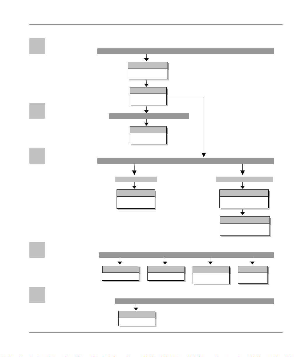
Orientation Map
The following Orientation Map is designed to guide you through a quick and correct
installation of your Prestige. According to your particular application (Internet,
Telecommuting, LAN-to-LAN Connection), follow the path outlined in this Orientation Map
to refer to the appropriate chapters in this manual. Read the instructions in each chapter
carefully for a successful configuration of your Prestige.
xvi
Page 17
Preface
INSTALLATION
Chapter 2
Chapter 3
Chapter 11
Chapter 10
Chapter 9
Chapter 8
Chapter 7
DIAL-IN
LAN-TO-LAN
12345
Chapter 6
Chapter 4
Chapter 5
Chapter 1
INTERNET ACCESS
ADVANCED
APPLICATIONS
Orientation Map
Getting to Know your
Internet Access Router
Hardware
Installation
Internet Access
Application
Prestige 100WH Internet Access Router
APPLICATIONS
MANAGEMENT &
MAINTENANCE
Filter Configuration
TROUBLESHOOTING
Dial-in Server
Applications
Troubleshooting
APPLICATIONS
System Password
Telnet Configuration
and Capabilities
Remote Node Configuration
Remote Node
TCP/IP Configuration
System
Maintenance
xvii
Page 18

Page 19

Prestige 100WH Internet Access Router
Chapter 1 Getting to Know Your Internet Access Router
Chapter 1
Getting to Know Your Internet Access
Router
This chapter describes the key features and applications of your Prestige 100WH Internet
Access Router.
1.1 Prestige 100WH Internet Access Router
Congratulations on the purchase of your ZyXEL Prestige 100WH Internet Access Router.
Your Prestige integrates a 4-port hub and one high-speed WAN (Wide Area Network) port
into a single package. The Prestige is ideal for everything from Internet browsing to dial-in
server to making LAN-to-LAN connections to remote networks.
1.2 Features of Prestige 100WH
Your Prestige is packed with a number of features that give it the flexibility to provide a
complete networking solution for almost any user.
l Ease of Installation
Your Prestige is quick and easy to install. Physically, it resembles an external modem except
for the fact that it is a router/hub.
l High-Speed WAN Port
The high speed RS232 WAN port allows you to use either a modem or an ISDN TA (Terminal
Adapter) for your wide area networking applications.
1-1
Page 20

Prestige 100WH Internet Access Router
Chapter 1 Getting to Know Your Internet Access Router
l Protocols Supported
u TCP/IP (Transmission Control Protocol/Internet Protocol) network layer protocol.
u PPP (Point-to-Point Protocol) link layer protocol.
u SUA™ (Single User Account) and NAT (Network Address Translation).
l Integrated 4-Port Ethernet Hub
The built-in 4-port Ethernet 10base-T hub saves you the cost and the clutter of an external
hub.
l Dial-On-Demand
The Dial-On-Demand feature allows the Prestige to automatically place a call whenever you
use your router to access the Internet.
l Full Network Management
Your Prestige allows menu-driven network management via an RS-232/telnet connection or
the Java-based PWC. Your Prestige is also equipped with a Call Detail Record to help analyze
and manage your telephone bill.
l PAP and CHAP Security
The Prestige supports PAP (Password Authentication Protocol) and CHAP (Challenge
Handshake Authentication Protocol). CHAP is more secure since the password is scrambled
prior to transmission. However, PAP is readily available on more platforms.
l DHCP Support
DHCP (Dynamic Host Configuration Protocol) allows you to automatically assign TCP/IP
settings to hosts on your network.
l Call Control
Your Prestige provides budget management for outgoing calls and maintains a blacklist for
unreachable phone numbers in order to save you the expense of unnecessary charges.
1-2
Page 21

Prestige 100WH Internet Access Router
Chapter 1 Getting to Know Your Internet Access Router
l Data Compression
Your Prestige incorporates Stac data compression to speed up data transfer. Stac is the de
facto standard for compression over PPP links.
l Networking Compatibility
Your Prestige is compatible with remote access products from other manufacturers such as
Ascend, Cisco, and 3Com. Furthermore, it supports Microsoft Windows 95 and Windows NT
remote access capability.
1.3 The WAN Port
The WAN port is a high-speed, asynchronous RS232 serial port that allows you to connect a
modem or an ISDN Terminal Adapter (TA) to the Prestige. For brevity’s sake, we will refer to
a modem or a TA categorically as an “external WAN device”, or simply a “WAN device”
from now on.
The WAN port supports up to 460.8 kbps (kilobits per second) throughout, which is more than
twice as fast as the fastest modem with V.42bis compression.
1.3.1 Terminology
l DCE & DTE
On the two ends of an RS-232 connection, the equipment closest to the telephone line is
called the DCE (Data Communications Equipment) and the other the DTE (Data Terminal
Equipment). In our case, the modem or the ISDN TA is the DCE, and the Prestige is the DTE.
l PSTN & POTS
Collectively, the voice grade network of the telephone companies is called PSTN (Public
Switched Telephone Network), and a regular telephone line is often referred to as a POTS
(Plain Old Telephone Service)
1-3
Page 22
Prestige 100WH Internet Access Router
Chapter 1 Getting to Know Your Internet Access Router
1
2
3
4
143
2
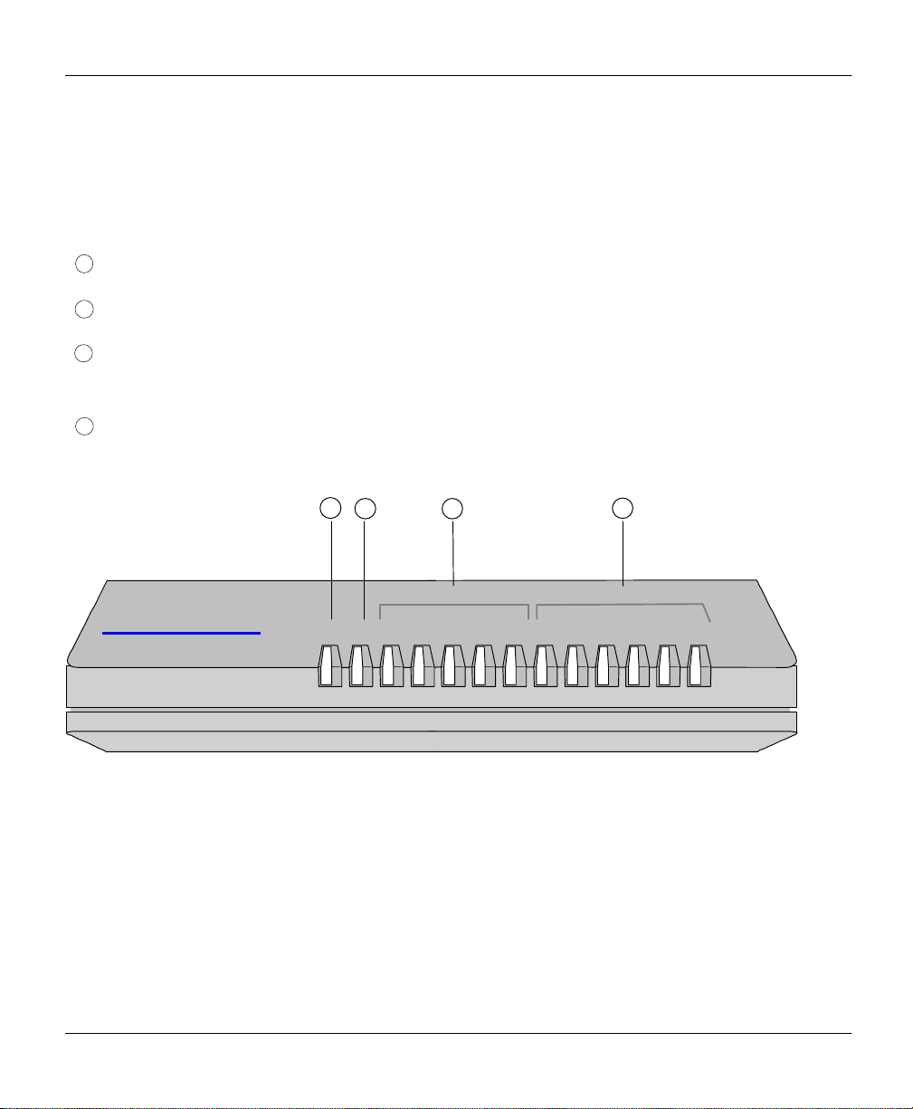
1.4 Prestige 100WH Front Panel
1.4.1 Front Panel Description
: PWR = Power LED
:RUN = Normal Operation (Blinking)
: ETHERNET (COL, 1, 2, 3, 4) = 4-PORT 10Base-T HUB (Collisions on LAN, Active Ethernet Port
#)
: WAN (RDY, TXD, RXD, DTR, RTS, CTS) = WAN Port (Ready, Transmit, Receive, DTE Ready,
Request to Send, Clear to Send)
ETHERNET
Prestige 100WH
Internet Access Router
RUN
1 2 3 4 RDY TXD RXD DTR RTS CTSPWR COL
Figure 1-1. Prestige 100WH Front Panel
1-4
WAN
Page 23

Prestige 100WH Internet Access Router
Chapter 1 Getting to Know Your Internet Access Router
1.4.2 Front Panel LEDS
The LED indicator lights on the front panel indicate the operational status of your Prestige.
The following table describes the LED functions:
Table 1-1. LED Functions
LED Function Indicator
Active Description
Status
PWR Power LED Green On Power is being applied to the Prestige.
RUN Running
Status LED
ETHER
-NET
WAN
Port
COL Collisions Green On Transmission collisions have occurred
1,2,3,4 Link status
& Activity
RDY Ready Green On The WAN port is ready.
CD Carrier
Detect
TXD Transmit Green Blinking Traffic is being transmitted from the
RXD Receive Green Blinking Traffic is being received from the WAN
Green Blinking The Prestige is functioning properly.
on the LAN.
Green
Green On The connection is ready for data
On An active station is connected to the
port.
Blinking The station connected to the port is
transmitting.
transfer.
Prestige.
device.
RTS Request to
Send
CTS Clear to
Send
Green On The Prestige is ready to receive data.
Green On The WAN device is ready to receive
data.
1-5
Page 24
Prestige 100WH Internet Access Router
Chapter 1 Getting to Know Your Internet Access Router
1
2
3
4
143
2
1.4.3 WAN Port Status LEDs
CD (Carrier Detect) signal is sent by the WAN device to indicate that line negotiation is
successful and that it is ready for data transfer.
RTS (Request to Send) and CTS (Clear to Send) are hardware flow control signals. RTS is
from the DTE (the Prestige) while CTS is from the DCE (the WAN device).
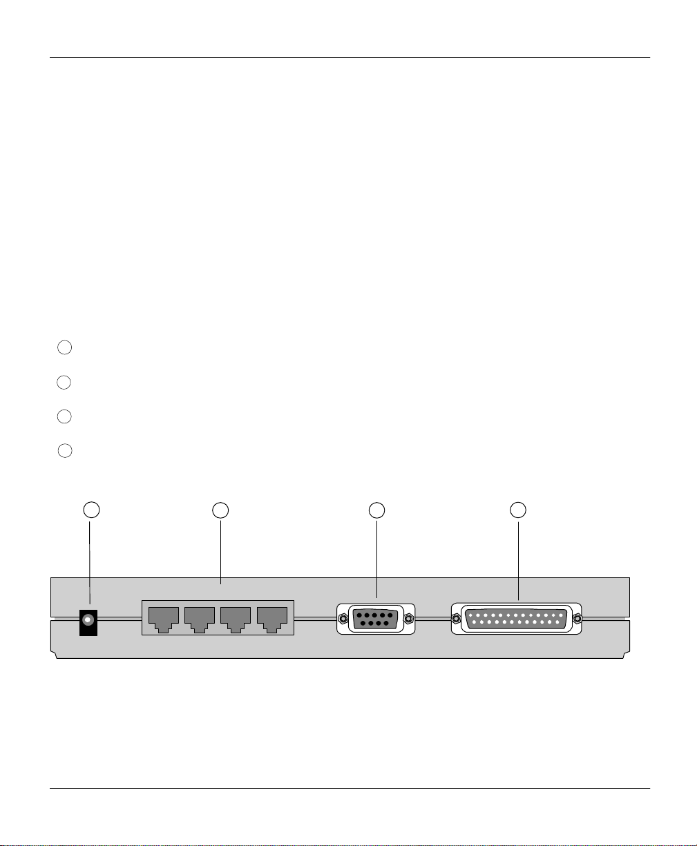
1.5 Prestige 100WH Back Panel
The following figure helps you identify the rear panel ports of your Prestige 100WH. Refer to
this diagram when attempting to make connections.
:POWER = Input power connector to the AC adapter.
: ETHERNET = 4 x RJ-45 ETHERNET 10Base-T ports.
:CONSOLE = DB-9 (female) Console port.
:WAN = DB-25 (male) WAN port.
ETHERNET
POWER
1-6
4 3 2 1
Figure 1-2. Prestige 100WH Back Panel
CONSOLE
WAN
Page 25

Prestige 100WH Internet Access Router
Chapter 1 Getting to Know Your Internet Access Router
ISP
INTERNET
LAN
1.6 Applications for Prestige 100WH
The Prestige offers complete solutions for your WAN applications such as Internet Access,
LAN-to-LAN Connections, telecommuting and remote access.
1.6.1 Internet Access
The Prestige is the ideal high-speed solution for Internet Access. Your Prestige supports the
TCP/IP protocol, which is the lingua franca of the Internet. It is also compatible with access
servers manufactured by major vendors such as Cisco and Ascend. A typical Internet Access
application is shown in Figure 1-3.
Figure 1-3. Internet Access Application
PSTN/ISDN Network
1.6.2 Internet Single User Account
For a small office environment, the Single User Account (SUA) feature allows multiple users
on the LAN to access the Internet concurrently for the cost of a single user. The Single User
Account address mapping can also be used for LAN to LAN connection.
Modem / ISDN TA
Modem
ISDN TA
Ethernet LAN
RS-232
Prestige 100WH
1-7
Page 26
Prestige 100WH Internet Access Router
Chapter 1 Getting to Know Your Internet Access Router
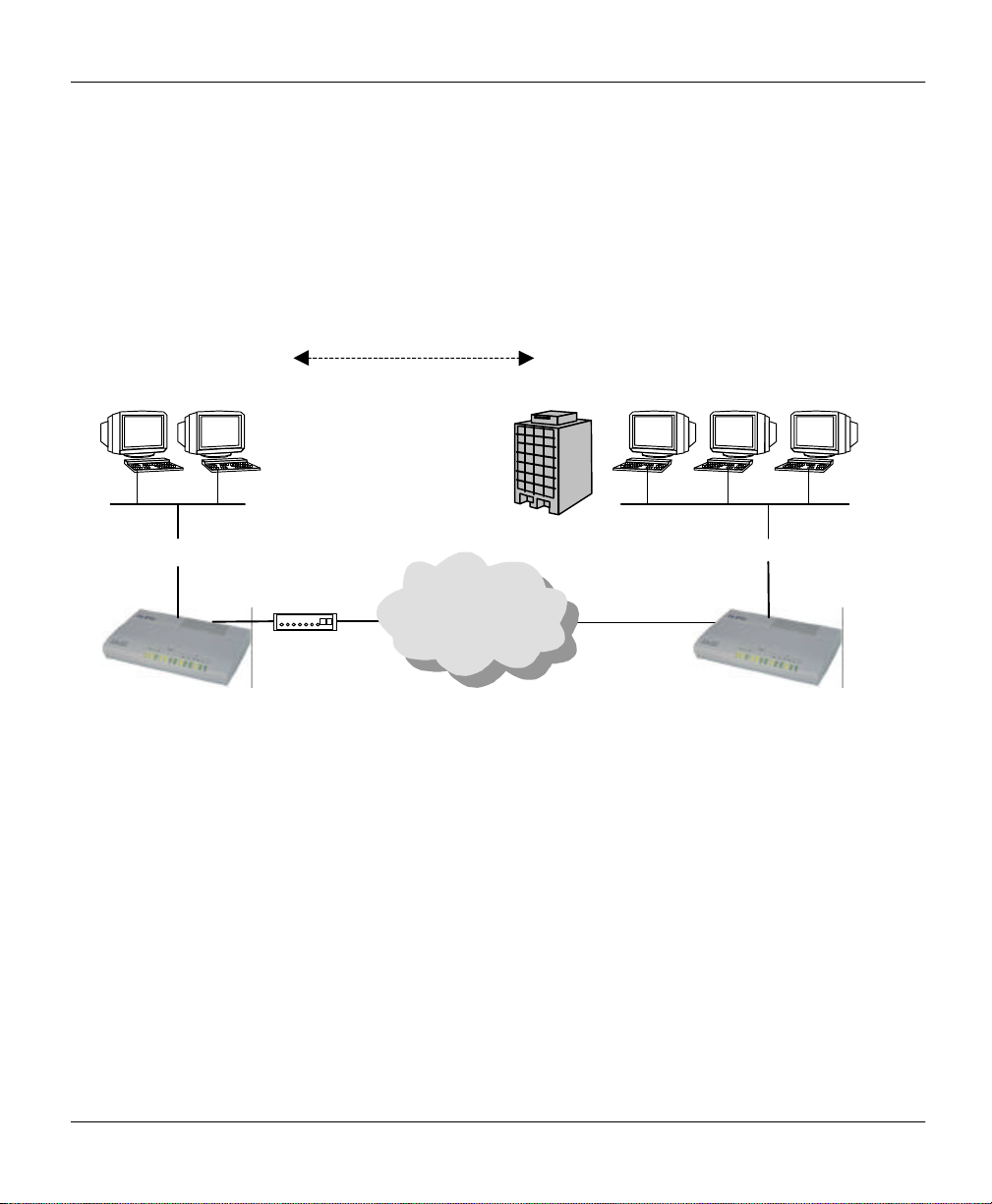
1.6.3 LAN-to-LAN Connection
Your Prestige can dial to and answer calls from another remote access router. A typical LANto-LAN application for your Prestige is to connect the Corporate Office LAN with the Branch
Office, as shown in Figure 1-4.
Branch Office LAN
Ethernet LAN
Prestige 100WH
Figure 1-4. LAN-to-LAN Connection Application
Modem / ISDN TA
Modem
ISDN TA
Corporate LAN
Ethernet LAN
PSTN/ISDN Network
Prestige Router
1-8
Page 27
Prestige 100WH Internet Access Router
Chapter 1 Getting to Know Your Internet Access Router
Telecommuter
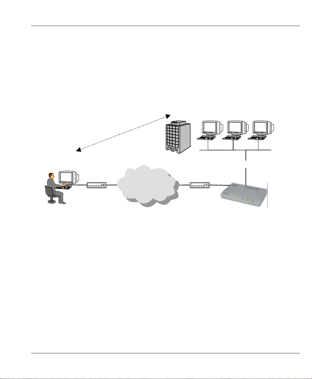
1.6.4 Remote Access Server
Your Prestige allows remote users to dial-in and gain access to your LAN. This feature
enables users that have workstations with remote access capabilities (for example, Windows
95), to dial in using a modem to access the network resources without physically being in the
office. Figure 1-5 shows how a remote user can connect to its corporate office via a modem.
Corporate LAN
Remote User
Modem / ISDN TA
Modem
ISDN TA
PSTN/ISDN Network
Modem / ISDN TA
Modem
ISDN TA
Ethernet LAN
Prestige 100WH
Figure 1-5. Telecommuting/Remote Access Application
Either PAP or CHAP authentication may be used to control the access from remote users to
the corporate LAN. You can also use call-back for security and/or accounting purposes.
1-9
Page 28

Page 29

Prestige 100WH Internet Access Router
Chapter 2 Hardware Installation & Initial Setup
Chapter 2
Hardware Installation & Initial Setup
2.1 Unpacking your Internet Access Router
Before you proceed further, check all items you received with your Prestige against this list to
make sure nothing is missing. The complete package should include:
Table 2-1. Item Checklist
Package Contents Prestige 100WH
Prestige 100WH Internet Access Router
Power Adapter
DB-9 female/DB-9 male RS-232 Cable
DB-25 female/DB-9 male Console Cable Adapter
LAN Straight Cable (white tag)
Warranty Card
Instruction Card
Prestige 100WH Quick Start Guide
Prestige 100WH User's Manual
Prestige Web Configurator CD
Prestige Web Configurator User’s Manual
1
1
1
1
1
1
1
1
1
1
1
2-1
Page 30

Prestige 100WH Internet Access Router
Chapter 2 Hardware Installation & Initial Setup
2.2 Additional Installation Requirements
In addition to the contents of your package, there are other hardware and software
requirements you need before you can install and use your Prestige. These requirements
include:
l A computer with Ethernet 10Base-T NIC (Network Interface Card).
l A computer equipped with communications software (for example, Hyper Terminal in
Win95) configured to the following parameters:
Ø VT100 terminal emulation.
Ø 9600 Baud rate.
Ø No parity, 8 Data bits, 1 Stop bit.
After the Prestige has been successfully connected to your network, you can make future
changes to the configuration through telnet application.
2-2
Page 31

Prestige 100WH Internet Access Router
Chapter 2 Hardware Installation & Initial Setup
Power
Power
2.3 Connect your Internet Access Router
2.3.1 Prestige 100WH Connections
PSTN/ISDN Network
Adapter
Outlet
Computer
ETHERNET
Fractional T1/E1
Modem
ISDN TA
CSU/DSU
Modem / ISDN TA
POWER
4 3 2 1
Ethernet LAN
Figure 2-1. Connect Prestige 100WH
CONSOLE
WAN
2-3
Page 32

Prestige 100WH Internet Access Router
Chapter 2 Hardware Installation & Initial Setup
This section outlines how to connect your Prestige to the LAN and the telephone line. Refer
to Figure 1-2 to identify all of the ports. Then see Figure 2-1 when you attempt to make the
various connections.
Follow these steps for a quick and correct installation of your Prestige.
Step 1. Connect Your Computer and Your Prestige
For the initial setup and configuration of your Prestige, you must use a terminal emulator on a
workstation and connect the workstation’s serial (COM) port to the console port
with a RS-232 cable.
After your Prestige has been successfully installed, you can modify the configuration through
a remote telnet connection. See Chapter 9 - Telnet Configuration and Capabilities for detailed
instructions on using telnet to configure your Prestige.
Step 2. Connect the WAN Device
Connect the DTE port of the WAN device to the WAN port of the Prestige with a RS-232
cable. Please follow the instructions of your WAN device to connect it to the telephone or
ISDN network and to the power outlet. Power on the WAN device.
Step 3. Ethernet Connections
Use Ethernet ports 1, 2, 3 and 4 at the rear panel to create an Ethernet 10Base-T network.
Connect a workstation to the Prestige using a straight-through 10Base-T cable, which is a
Unshielded Twisted Pair (UTP) cable with RJ-45 connectors that look like a bigger telephone
plug with 8 pins.
Step 4. Connect the Power Adapter to your Prestige
Plug the power adapter into the port labeled POWER on the rear panel of your Prestige.
2-4
Page 33

Prestige 100WH Internet Access Router
Chapter 2 Hardware Installation & Initial Setup
2.4 Connecting External Hubs
The Prestige can accommodate up to 4 workstations on the built-in Ethernet hub; if you have
more than 4, then you need an external hub for the additional ones. If this is the case, connect
the external hub to the Prestige using a straight-through cable from the uplink port of the
external hub to one of the 4 Ethernet ports of the Prestige. Please make sure that the uplink
port on the external hub is in the uplink mode (usually with a toggle switch). If your external
hub does not have an uplink port, then you must use a crossover cable to daisy-chain it to the
Prestige.
2.5 Power On Your Prestige
At this point, you should have connected the computer, the telephone line, the Ethernet cable,
and the power supply to your Prestige. You can now power on your Prestige by plugging the
AC adapter to the appropriate power outlet.
Step 1. Initial Screen
When you power on your Prestige, the Internet Access Router performs several internal tests
and performs a modem initialization. After initialization, the Prestige asks you to press
[Enter] to continue, as shown in Figure 2-2.
Figure 2-2. Power-On Display
Copyright (c) 1994 - 1998 ZyXEL Communications Corp.
ethernet address: 00:a0:c5:00:10:32
Wan port init ... done
Modem init . inactive
Press ENTER to continue...
2-5
Page 34

Prestige 100WH Internet Access Router
Chapter 2 Hardware Installation & Initial Setup
Enter Password
The Login screen appears prompting you to enter the password, as shown in Figure 2-3.
For your first login, enter the default password “1234” to get into the Main Menu of the
System Management Terminal (SMT). As you type a password, the screen displays an (X) for
each character you typed.
Enter Password : XXXX
Figure 2-3. Login Screen
1. Note that the default password is “1234”.
2. Note that if there is no activity for longer than 5 minutes, your Prestige will
automatically log you out and display a blank screen. If you see a blank screen, press
[Enter] to bring up the password screen.
2-6
Page 35

Prestige 100WH Internet Access Router
Chapter 2 Hardware Installation & Initial Setup
2.6 Navigating the SMT Interface
The SMT (System Management Terminal) is the interface that you use to configure your
Prestige.
Several operations that you should be familiar with before you attempt to modify the
configuration are listed in Table 2-2.
Table 2-2. Main Menu Commands
Operation Press/<read> Description
Move forward to
another menu
Move backward
to a previous
menu
Move the cursor
Enter information Fill in, or
Required fields <?>
N/A fields <N/A>
Save your
configuration
Exit the SMT Type 99, then
[Enter] To move forward to a sub-menu, type in the number of the
[Esc] Press the [Esc] key to move back to the previous menu.
[Enter] or
[Up]/[Down]
arrow keys
Press the
[Space bar] to
toggle
[Enter] Save your configuration by pressing [Enter] at the
press [Enter].
desired sub-menu and press [Enter].
Within a menu, press [Enter] to move to the next field. You can
also use the [Up]/[Down] arrow keys to move to the previous
and the next field, respectively.
There are two types of fields that you will need to fill in. The first
requires you to type in the appropriate information. The second
gives you choices to choose from. In the second case, press the
[Space bar] to cycle through the available choices.
All fields with the symbol <?> must be filled in order be able to
save the new configuration.
Some of the fields in the SMT will show a <N/A>. This symbol
refers to an option that is not available.
message:[Press ENTER to confirm or ESC to cancel]. Saving
the data on the screen will take you, in most cases to the
previous menu.
Type 99 at the Main Menu prompt and press [Enter] to exit the
SMT interface.
2-7
Page 36

Prestige 100WH Internet Access Router
Chapter 2 Hardware Installation & Initial Setup
The SMT displays the Main Menu, as shown in Figure 2-4.
Copyright (c) 1994 - 1998 ZyXEL Communications Corp.
Getting Started
1. General Setup
2. Wan Setup
3. Ethernet Setup
4. Internet Access Setup
Advanced Applications
11. Remote Node Setup
12. Static Routing Setup
13. Default Dial-in Setup
14. Dial-in User Setup
Figure 2-4. SMT Main Menu
Prestige 100WH Main Menu
Advanced Management
21. Filter Set Configuration
23. System Password
24. System Maintenance
99. Exit
Enter Menu Selection Number:
2.6.1 System Management Terminal Interface Summary
Table 2-3. Main Menu Summary
# Menu Title Description
1 General Setup Access this menu to setup general information.
2 Modem Setup Access this menu to setup modem configuration.
3 Ethernet Setup Access this menu to setup Ethernet configuration.
4 Internet Access Setup A quick and easy way to setup Internet connection.
11 Remote Node Setup Access this menu to setup the remote nodes, including Internet
connection. Prestige supports up to four remote nodes.
12 Static Routing Setup Access this menu to setup static routes. There are four static routes for
this protocol.
13 Default Dial-in Setup Access this menu to setup default dial-in parameters so that your
Prestige can be used as a dial-in server.
14 Dial-in User Setup Setup remote dial-in user. Prestige has eight remote dial-in users.
21 Filter Set Configuration Setup filters to provide security, call control, etc.
23 System Password Access this menu to setup the password to access the SMT.
24 System Maintenance Provides system status, diagnostics, firmware upload, etc.
99 Exit To exit from SMT and return to the blank screen.
2.7 Changing the System Password
2-8
Page 37

Prestige 100WH Internet Access Router
Chapter 2 Hardware Installation & Initial Setup
Follow these steps to change the default system password:
Step 1. Select option [23. System Password] in the Main Menu.
Step 2. When Menu 23 - System Password appears, as shown in Figure 2-5, type in your
existing system password, i.e., 1234, then press [Enter].
Figure 2-5. Menu 23.1 - System Password
Step 3. Enter your new system password and press [Enter].
Menu 23 - System Password
Old Password= XXXX
New Password= XXXX
Retype to confirm= XXXX
Enter here to CONFIRM or ESC to CANCEL:
Step 4. Re-type your new system password for confirmation and press [Enter].
Note on Password Field
As you type the password, the screen displays an (X) for each character you type.
2-9
Page 38

Prestige 100WH Internet Access Router
Chapter 2 Hardware Installation & Initial Setup
2.8 General Setup
The Menu 1 - General Setup contains administrative and system-related information.
To enter Menu 1 and fill in the required information, follow these steps:
Step 1. Select option [1. General Setup] in the Main Menu by typing 1 at the menu
selection number prompt.
Step 2. The Menu 1 - General Setup screen appears, as shown in Figure 2-6. Fill in the
required fields marked [?], as explained in Table 2-4.
Menu 1 - General Setup
System Name= P100WH
Location= location
Contact Person's Name= name
Press ENTER to Confirm or ESC to Cancel:
Figure 2-6. Menu 1 - General Setup
2-10
Page 39

Prestige 100WH Internet Access Router
Chapter 2 Hardware Installation & Initial Setup
Table 2-4. General Setup Menu Fields
Field Description
System Name Choose a descriptive name for identification purposes. This name can be up
to 8 alphanumeric characters long. Spaces are not allowed, but dashes “-”
and underscores "_" are accepted.
Location
(optional)
Contact
Person's Name
(optional)
Enter the geographic location (up to 31 characters) of your Prestige.
Enter the name (up to 8 characters) of the person in charge of this Prestige.
2-11
Page 40

Prestige 100WH Internet Access Router
Chapter 2 Hardware Installation & Initial Setup
2.9 Prestige 100WH WAN Port Setup
This section describes how to configure the WAN port and the connected WAN device on
your Prestige with Menu 2-WAN Port Setup. If advanced setup is required, go into Menu 2.1.
When you are finished, press [Enter] in Menu 2.1 to save your configuration.
2.9.1 WAN Port Setup
To configure the WAN Port on the Prestige, follow these steps:
Step 1. Select option [2. WAN Port Setup] in the Main Menu by typing 2 at the menu
selection number prompt.
Step 2. This will bring up Menu 2 –WAN Port Setup, as shown in Figure 2-7.
Menu 2.1 – WAN Port Setup
Modem Name= ZyXEL
Active= Yes
Direction= Outgoing
Phone Number=
Port Speed=
Press ENTER to Confirm or ESC to Cancel:
Figure 2-7. Menu 2.1 – WAN Port Setup
2-12
AT Command String
Init= at&fs0=0w2s95=1
Advanced Setup= No
Page 41

Prestige 100WH Internet Access Router
Chapter 2 Hardware Installation & Initial Setup
Table 2-5 describes how to configure the internal modem.
Table 2-5. WAN Port Setup Menu Fields
Field Description
Modem Name Enter a descriptive name for the WAN device on the WAN Port.
Active Set to [Yes] to activate the WAN port.
Call Direction Set the call direction for the WAN device.
Phone Number Enter the telephone number assigned to your line by your telephone
company. Note that your Prestige only accepts digits; do not include
dashes and spaces in this field.
Port Speed Press the space bar to select the speed of the RS-232 link between
Prestige and the WAN device. The speed should be close to 4 times the
speed of the WAN device. For example, 230400.
AT Command
String: Init
Advanced Setup To edit the Advanced Setup for this internal modem, move the cursor to
Enter the AT commands to initialize the WAN device at Prestige start up.
The string is sent to the WAN device again whenever it is modified. For
example, [at&fs0=0w2s95=1].
this field, use the space bar to select [Yes] and press [Enter]. This will bring
you to Menu 2.1.1 - Advanced WAN Setup.
The default initialization string tells a modem to load factory default (&f), not to answer any
incoming call (s0=0), and to report line speed (w2) and in “CONNECT speed” format
(s95=1). If you have an ISDN TA, please consult its documentation.
2-13
Page 42

Prestige 100WH Internet Access Router
Chapter 2 Hardware Installation & Initial Setup
2.9.2 Advanced WAN Port Setup
The Advanced WAN Port Setup Menu allows you to configure the AT Commands for the
WAN device and the call control parameters.
Step 1. In Menu 2.1, move the cursor to the Advanced Setup field and press the space bar
to select [Yes], then press [Enter].
Step 2. When Menu 2.1.1 appears, fill in the appropriate AT commands and call control
parameters, as shown in Figure 2-8.
Menu 2.1.1 - Advanced WAN Setup
AT Command Strings:
Dial=atdt
Drop= --+++--ath
Answer= ata
Drop DTR When Hang Up= Yes
AT Response string:
CLID= NMBR
Called= TO
Speed= CONNECT
Enter here to CONFIRM or ESC to CANCEL:
Call Control:
Dial Timeout(sec)= 60
Retry Counter= 0
Retry Interval(sec)= N/A
Drop Timeout(sec)= 20
Call Back Delay(sec)= 15
Figure 2-8. Menu 2.1.1 - Advanced WAN Setup
2-14
Page 43

Prestige 100WH Internet Access Router
Chapter 2 Hardware Installation & Initial Setup
Refer to Table 2-6 for details on how to fill in the AT commands fields.
Table 2-6. Advanced WAN Setup Fields
Field Description
AT Command Strings:
Dial
Drop
Answer
Drop DTR When Hang Up If this field is set to [Yes], the Prestige will drop the DTR signal
AT Response Strings:
CLID
The AT commands needed to dial.
The default setting in this field is [atdt].
The AT command needed to drop a call.
The default setting in this field is [+++ath].
The AT command needed to answer an incoming call.
The default setting in this field is [ata].
when hanging up a call.
These strings specify the characters immediately preceding the
various responses from the WAN device.
The string preceding the CLID (the number of calling party).
The default setting in this field is NMBR.
Called ID
The string preceding the dialed number.
The default setting in this field is TO.
Speed
The string preceding the DCE speed.
The default setting in this field is CONNECT.
When you have completed this menu, press [Enter] to return to Menu 2.1.
At Command Strings
For regular telephone lines, the default “Dial” string tells the modem that the line uses tone
dialing. If your switch still requires pulse dialing, change the string to [atdp]. For ISDN lines,
there are far more protocols and operational modes. Please consult the documentation of your
TA, for you may need additional commands in both “Dial” and “Init” strings.
The default AT strings should work fine for the majority of modems. Please consult the
documentation of your WAN device if you need to alter them for your specific situation,
especially if you have an ISDN TA.
2-15
Page 44

Prestige 100WH Internet Access Router
Chapter 2 Hardware Installation & Initial Setup
DTR Signal
The majority of WAN devices default to hanging up the current call when the DTR (Data
Terminal Ready) signal is dropped by the DTE. When “Drop DTR When Hang Up” is set to
yes, the Prestige will use this hardware signal to force the WAN device to hang up, in addition
to issuing the drop command [ATH].
Response Strings
The response strings tell the Prestige the tags, or labels, immediately preceding the various
call parameters sent from the WAN device. The response strings have not been standardized;
please consult the documentation of your WAN device to find the correct tags.
Call Control Parameters
Table 2-7 below describes the call control parameters.
Table 2-7. Advanced Modem Setup Call Control Parameters
Field Description
Dial Timeout
(sec)
Retry Count How many times a busy or no-answer phone number is retried before it is put
Retry Interval
(sec)
Drop Timeout
(sec)
Call Back Delay
(sec)
The Prestige will disconnect if it can not set up an outgoing call within the
timeout value.
The default in this field is [60] seconds.
on the blacklist.
The default in this field is [0] to disable the blacklist control.
Elapsed time after a call fails before another call is retried. Applies before a
phone number is blacklisted.
The Prestige will drop the DTR signal if it does not receive a positive response
within this timeout period after it tells the WAN device to hang up.
The default in this field is [20] seconds.
Elapsed time between dropping a callback request call and dialing a callback
call.
The default in this field is [15] seconds.
2-16
Page 45

Prestige 100WH Internet Access Router
Chapter 3 Internet Access Application
Chapter 3
Internet Access Application
This chapter shows you how to configure your Prestige 100WH for Internet Access.
3.1 Ethernet Setup
This section describes the Ethernet Setup Menu. From the Main Menu, enter 3, then the Menu
3- Ethernet Setup displays as shown in Figure 3-1.
Figure 3-1. Menu 3 - Ethernet Setup
Menu 3 - Ethernet Setup
1. General Setup
2. TCP/IP and DHCP Setup
Enter Menu Selection Number:
3-1
Page 46

Prestige 100WH Internet Access Router
Chapter 3 Internet Access Application
The General Setup menu allows you to define the filter sets that you wish to apply to your
Ethernet traffic. From Menu 3 - Ethernet Setup, enter 1 to go to Menu 3.1 -General Ethernet
Setup.
Menu 3.1 - General Ethernet Setup
Input Filter Sets=
Output Filter Sets=
Press ENTER to Confirm or ESC to Cancel:
Figure 3-2. Menu 3.1 - General Ethernet Setup
Filters are not required for your Prestige to function properly. However, input and output filter
sets may be useful to block certain packets, reduce traffic, and prevent a security breach on
your Ethernet.
If you have a need for filters, read about Chapter 7 - Filter Set Configuration, then return to
this menu to define the appropriate filter sets.
3.2 TCP/IP Ethernet and DHCP Setup
3.2.1 IP Address and Subnet Mask
The Prestige is pre-configured in the factory with an IP address of 192.168.1.1 and a subnet
mask of 255.255.255.0 (Class C). This setup should work fine for the basic Internet access
application. It is strongly recommend that you do not change them, unless your ISP or
network administrator assigns you a block of registered IP addresses.
3-2
Page 47

Prestige 100WH Internet Access Router
Chapter 3 Internet Access Application
Note on IP Address Assignment
Every machine on your Ethernet network must have a unique IP address. Do not assign
an arbitrary address to any machine on your network; or else your machines will not
communicate to each other, let alone accessing the Internet.
3.2.2 RIP Setup
RIP (Routing Information Protocol) allows a router to exchange routing information with
other routers. The RIP Direction field controls the sending and receiving of RIP packets.
When set to both, the Prestige will broadcast its routing table periodically and incorporate the
RIP information that it receives; when set to none, it will not send any RIP packets and will
ignore any RIP packets received.
The Version field controls the format and the broadcasting method of the RIP packets that the
Prestige sends (it recognizes both formats when receiving). RIP-1 is universally supported;
but RIP-2 carries more information. RIP-1 is probably adequate for most networks, unless you
have a unusual network topology.
Both RIP-2B and RIP-2M sends the routing data in RIP-2 format; the difference being that
RIP-2B uses subnet broadcasting while RIP-2M uses multicasting. Multicasting can reduce
the load on non-router machines since they generally do not listen to the RIP multicast
address and so will not receive the RIP packets. However, if one router uses multicasting, then
all routers on your network must use multicasting, as well.
By default, RIP direction is set to both and the version set to RIP-1.
3.2.3 DHCP Configuration
DHCP (Dynamic Host Configuration Protocol) allows the individual clients (workstations) to
obtain the TCP/IP configuration at start-up from a centralized DHCP server. The Prestige has
the DHCP server capability built-in and is enabled by default.
3-3
Page 48

Prestige 100WH Internet Access Router
Chapter 3 Internet Access Application
IP Pool Setup
The Prestige is pre-configured with a pool of 32 IP addresses starting from 192.168.1.33 to
192.168.1.64. This configuration leaves 31 IP addresses (excluding the Prestige itself) in the
lower range for other server machines, e.g., server for mail, FTP, telnet, web, etc., that you
may have.
DNS Sever Address(es)
DNS (Domain Name System) is for mapping a domain name to its corresponding IP address
and vice versa, e.g., the IP address of www.zyxel.com is 204.217.0.2. The DNS server(s) is
extremely important because without it, you must know the IP address of a machine before
you can access it. The DNS server address(es) that you enter in the DHCP setup is passed to
the client machines along with the assigned IP address and subnet mask. Make sure that you
obtain the IP address of the DNS server(s) from your ISP. Your workstations will need this
information even if you don’t use the Prestige’s DHCP server.
3.2.4 More on IP Address and Subnet Mask
Similarly to the houses on a street that share a common street name, the machines on a LAN
share one common network number.
Where you obtain your network number depends on your particular situation. If the ISP or
your network administrator assigns you a block of registered IP addresses, follow their
instructions in selecting the IP addresses and the subnet mask.
If you subscribe to an ISP and the ISP did not explicitly give you an IP network number, then
most likely you have a single-user account. If this is the case, it is recommended that you
select a network number from 192.168.0.0 to 192.168.255.0 (ignoring the trailing zero). The
Internet Assigned Number Authority (IANA) reserved this block of addresses specifically for
private use; please do not use any other number unless you are told otherwise. Let’s say you
select 192.168.1.0 as the network number; which covers 254 individual addresses, from
192.168.1.1 to 192.168.1.254 (zero and 255 are reserved). In other words, the first 3 numbers
specify the network number while the last number identifies an individual workstation on that
network.
3-4
Page 49

Prestige 100WH Internet Access Router
Chapter 3 Internet Access Application
Once you have decided on the network number, pick an IP address that is easy to remember,
for example, 192.168.1.1, for your Prestige.
The subnet mask specifies the network number portion of an IP address. Your Prestige will
compute the subnet mask automatically based on the IP address that you entered. You do not
need to change the subnet mask computed by the Prestige unless instructed otherwise.
3.3 Configuring TCP/IP and DHCP
To edit Menu 3.2, select the menu option [3. Ethernet Setup] in the Main Menu. When
Menu 3 appears, select the submenu option [2. TCP/IP and DHCP Setup] and press
[Enter]. The screen now displays Menu 3.2 - TCP/IP and DHCP Ethernet Setup, as shown
in Figure 3-3.
Figure 3-3. Menu 3.2 - TCP/IP and DHCP Ethernet Setup
Menu 3.2 - TCP/IP and DHCP Ethernet Setup
DHCP Setup:
DHCP= Server
Client IP Pool Starting Address= 192.168.1.33
Size of Client IP Pool= 32
Primary DNS Server= N/A
Secondary DNS Server= N/A
TCP/IP Setup:
IP Address= 192.68.1.1
IP Subnet Mask= 255.255.255.0
RIP Direction= Both
Version= RIP-1
Press Space Bar to Toggle.
Enter here to CONFIRM or ESC to CANCEL:
3-5
Page 50

Prestige 100WH Internet Access Router
Chapter 3 Internet Access Application
Follow the instructions in Table 3-1.on how to configure the DHCP fields.
Table 3-1. DHCP Ethernet Setup Menu Fields
Field Description
DHCP
If DHCP=Server:
Client IP Pool Starting
Address
Size of Client IP Pool The count of the IP addresses in the pool.
Primary and Secondary
DNS Server
This field determines the mode of DHCP support. If set to [None],
DHCP will not be used. If it is set to [Server], your Prestige will
act as a DHCP server.
The default in this field is [Server].
When DHCP is used, the following four items need to be set:
The Client IP Pool Starting Address gives the first address in the
pool.
The default in this field is 192.168.1.33
The default in this field is 32.
Enter the IP address of the DNS server(s) provided by your ISP
or network administrator.
Table 3-2 contains instructions on how to configure your Prestige for TCP/IP Ethernet Setup.
Table 3-2. TCP/IP Ethernet Setup Menu Fields
Field Description
TCP/IP Setup
IP Address Enter the IP address of your Prestige in dotted decimal notation.
The default in this field is 192.168.1.1.
IP Subnet
Mask
RIP
Direction
Version Version of RIP packets sent by the Prestige. The default in this field is RIP-1.
When you have completed this menu, press [Enter] at the prompt [Press ENTER to Confirm…] to
save your configuration, or press [Esc] at any time to cancel.
Enter the subnet mask of your Prestige.
The default in this field is 255.255.255.0.
This parameter determines how your Prestige handles RIP traffic
(In/Out/both/none).
The default in this field is [Both].
3-6
Page 51

Prestige 100WH Internet Access Router
Chapter 3 Internet Access Application
3.4 Internet Access Configuration
Menu 4 of the SMT allows you to enter the Internet access configuration in one screen. Menu
4 is actually a simplified setup for one f the four available remote nodes that you can access
through menu 11. Before you configure your Prestige for Internet Access, you need to collect
your Internet account information from your ISP. You can use Table 3-3 to record your
Internet Account Information.
Table 3-3. Internet Account Information
Internet Account Information Write your account information here
IP Address of the ISP's Gateway (Optional)
Telephone Number(s) of your ISP
Login Name
Password
DNS Server Address(es)
From the Main Menu, enter option [4. Internet Access Setup] to go to Menu 4 - Internet
Access Setup, as displayed in Figure 3-4.
Figure 3-4. Menu 4 - Internet Access Setup
Menu 4 - Internet Access Setup
ISP's Name= ChangeMe
ISP Gateway IP Addr=
Pri Phone #= 1234
Sec Phone #=
My Login=
My Password= ********
Single User Account= Yes
Local IP Addr= 0.0.0.0
Server IP Addr= 0.0.0.0
Edit Script Options= No
Enter here to CONFIRM or ESC to CANCEL:
3-7
Page 52

Prestige 100WH Internet Access Router
Chapter 3 Internet Access Application
Table 3-4 contain instructions on how to configure your Prestige for Internet Access.
Table 3-4. Internet Access Setup Menu Fields
Field Description
ISP's Name Enter the name of your Internet Service Provider. (This information is for
identification purposes only.)
ISP IP Addr
(optional)
Pri(mary) Phone #
(required)
Sec(ondary) Phone #
(optional)
My Login Name
(required)
My Password
(required)
Single User Account
Local IP Addr:
Server IP Addr:
Enter the IP Address of the remote gateway at the ISP's site. If you do
not have this data, just leave it blank.
The first number your Prestige will dial to connect to the ISP.
If the Primary Phone number is busy or does not answer, your Prestige
will call the Secondary Phone number if available.
Enter the login name assigned to you by your ISP.
Enter the password associated with the login name above. Note that this
login name/password pair is only for your Prestige to connect to the
ISP's gateway. When you use TCP/IP applications (for example, FTP) to
access the Internet from your workstation, you will need a separate login
name and password for each server.
See Section 3.5 for detailed discussion on the Single User Account
feature. The default in this field is Yes.
If your ISP assigns you a static IP address, enter it in this field;
otherwise, leave it as 0.0.0.0. (default)
If you have a server that you want it to be accessible from the outside,
enter its local IP address in this field; otherwise, leave it as 0.0.0.0.
(default)
Edit Script Options To edit the parameters, select [Yes] and press [Enter]. This will bring you
to Menu 4.1 - Remote Node Script Options.
Press [Enter] at the prompt [Press ENTER to Confirm…] to save your configuration, or press
[Esc] at any time to cancel.
At this point, the SMT will ask if you wish to test the Internet connection. If you answer [y]
3-8
Page 53

Prestige 100WH Internet Access Router
Chapter 3 Internet Access Application
for yes, your Prestige will call the ISP to test the Internet setup. If the test fails, note the error
message that you receive on screen and take the appropriate troubleshooting steps.
3.5 Single User Account
Typically, if there are multiple users on the LAN wanting to access the Internet, they will have
to subscribe to multiple IP addresses from the ISP, which is generally more expensive than a
single user account.
The Single User Account (SUA) feature allows multiple workstations on your LAN to have
access to the Internet, but still only pay for one IP address, thus saving significantly on
subscription fees. (Check with your ISP before you enable this feature).
Figure 3-5 illustrates a typical Single User Account topology.
Private Network IP Addresses
192.168.1.33
192.168.1.34
192.168.1.35
192.168.1.36
Ethernet LAN
Assigned by User
IP Address
Assigned by ISP
192.168.1.1
Modem / ISDN TA
Modem
ISDN TA
Prestige 100WH
Figure 3-5. Single User Account Topology
INTERNET
3-9
Page 54

Prestige 100WH Internet Access Router
Chapter 3 Internet Access Application
The Single User Account feature may also be used to connect to remote networks other than
the Internet. For example, this feature can be used to simplify the allocation of IP addresses
when connecting branch offices to the corporate network.
The IP address for the SUA can be either fixed or dynamically assigned by the ISP (or another
remote node). In addition, you can also configure a server (for example, a Web server) on
your local network and make it accessible to outside users.
If you do not set a server IP address, SUA offers the additional benefit of firewall protection.
With SUA, all incoming inquiries will be filtered out by your Prestige if no server is defined.
This can prevent intruders from probing your network.
Your Prestige accomplishes this address sharing by translating the internal LAN IP addresses
to a single address that is globally unique on the Internet. For more information on IP address
translation, refer to RFC 1631, The IP Network Address Translator (NAT).
3.5.1 Advantages of SUA
The advantages of SUA include
l SUA is an ideal cost-effective solution for small offices with a few tens of hosts to
concurrently access the Internet or another remote TCP/IP network.
l SUA can provide one server to be accessible to the outside world.
l SUA can provide firewall protection if you do not configure a server. All incoming
inquiries will be filtered out by your Prestige, protecting your network.
l UDP and TCP datagrams can be routed. In addition, partial ICMP is supported.
Figure 3-5 above shows an example of a small office connecting to the Internet via SUA.
3-10
Page 55

Prestige 100WH Internet Access Router
Chapter 3 Internet Access Application
SUA
3.5.2 Configuration for Single User Account
The steps for configuring your Prestige for Single User Account are identical to the
conventional Internet Access (See configuration instructions in Table 3-4) with the exception
that you need to fill in three extra fields in Menu 4 - Internet Access Setup, as shown in Figure
3-6.
Menu 4 - Internet Access Setup
ISP's Name= ?
ISP Gateway IP Addr=
Pri Phone #= ?
Sec Phone #=
My Login=
My Password= ********
Single User Account= Yes
WAN IP Addr=
Server IP Addr=
Edit Script Options= No
Figure 3-6. Menu 4 - Internet Access Setup for Single User Account
To enable the SUA feature in Menu 4, move the cursor to the [Single User Account] field and
select [Yes] (or [No] to disable SUA). Then follow the instructions on how to configure the
SUA fields in Table 3-5.
Enter here to CONFIRM or ESC to CANCEL:
3-11
Page 56

Prestige 100WH Internet Access Router
Chapter 3 Internet Access Application
Table 3-5. Single User Account Menu Fields
Field Description
Single User Account Select [Yes] to enable SUA.
WAN IP Addr. If your ISP assigns you a dynamic IP address, enter [0.0.0.0] here.
If your ISP assigns you a static IP address, enter that IP address
here.
Server IP Addr. If you want to make an inside server (for example, a Web server)
accessible to outside users, enter that server's LAN IP address here.
Press [Enter] at the message [Press ENTER to Confirm ...] to save your configuration, or press
[Esc] at any time to cancel.
Please note that if you have an inside server that you want it to be visible to the outside world,
then it must have a fixed IP address and not depend on a DHCP server to assign it a dynamic
address.
At this point, your Prestige will ask if you wish to test the Internet connection. If you select
[Yes], your Prestige will call the ISP and test the connection. If the test fails, note the error
message that you receive and take the appropriate troubleshooting steps.
3.6 Configuring Backup ISP Accounts
If you have more than one ISP account, you can configure a remote node for the secondary
account as a backup instead of modifying Menu 4 all the time. The SUA feature can be
enabled for all of these accounts, making it convenient to switch to another ISP when one is
not available.
3-12
Page 57

Prestige 100WH Internet Access Router
Chapter 3 Internet Access Application
3.6.1 Configure a Backup ISP
To configure a backup ISP Account, follow these steps:
Step 1. Configure your primary ISP using Menu 4, as described earlier in this chapter.
Step 2. Enter Menu 11, then select the number of an unused remote node.
Step 3. In Menu 11.1, choose a name for your backup ISP account, then set the Active field
to [No], and enter your outgoing login name, password, and phone number(s). The
Remote IP Address field should be set to [1.1.1.1].
Step 4. In Menu 11.3, set the remote node's subnet mask to [0.0.0.0], and set RIP to [None].
Step 5. Save the new configuration.
Please note that the remote IP address of 1.1.1.1 is only a place-holder to avoid conflicting
with the IP address of the primary ISP, which is implicitly set at 0.0.0.0. When combined with
the subnet mask of 0.0.0.0, it creates a default route identical to the one derived from the
primary ISP when this remote node is activated.
3.6.2 To Switch ISP
Once you have done this, if you need to switch from your primary ISP to a backup ISP follow
these steps:
Step 1. Enter Menu 11 and select your Primary ISP.
Step 2. In Menu 11.1, set the Active field to [No].
Step 3. Enter Menu 11 again and select your Backup ISP.
Step 4. In Menu 11.1, set the Active field to [Yes].
You will now be able to access the Internet through the backup ISP remote node.
3-13
Page 58

Prestige 100WH Internet Access Router
Chapter 3 Internet Access Application
3.7 Editing Script Options
For some ISP, text login is required before it will start PPP negotiation. The Prestige provides
a script facility for this purpose. The script has six programmable sets; each is composed of an
‘Expect’ string and a ‘Send’ string. After matching the message from the server to the
Prestige returns the set’s ‘Send’ string to the server.
For instance, a typical login sequence starts with the server printing a banner, a login prompt
for you to enter the user name and a password prompt to enter the password:
Welcome to Acme, Inc.
Login: myLogin
Password:
To handle the first prompt, you specify “ogin: ” as the ‘Expect’ string and “myLogin” as the
‘Send’ string in set 1. The reason for leaving out the leading “L” is to avoid having to know
exactly whether it is upper or lower case. Similarly, you specify “word: ” as the ‘Expect’
string and your password as the ‘Send’ string for the second prompt in set 2.
Please note that the ordering of the sets is significant, i.e., starting from set 1, the Prestige will
wait until the ‘Expect’ string is matched before it proceeds to set 2, and so on for the rest of
the script. When both the ‘Expect’ and the ‘Send’ fields of the current set are empty, the
Prestige will terminate the script processing and start PPP negotiation. This implies two
things: first, the sets must be contiguous; the sets after an empty one are ignored. Second, the
last set should match the final message sent by the server. For instance, if the server prints
Login successful.
Starting PPP…
after you enter the password, then you should create a third set to match the final “PPP…”,
but without a “Send” string. Otherwise, the Prestige will start PPP prematurely right after
sending your password to the server.
3-14
Page 59

Prestige 100WH Internet Access Router
Chapter 3 Internet Access Application
If there are errors in the script and it gets stuck at a set for longer than the “Dial Timeout” in
menu 2 (default 60 seconds), the Prestige will timeout and drop the line. To debug a script, go
to Menu 24.4 to initiate a manual call and watch the trace display to see if the sequence of
messages and prompts from the server differs from what you expect.
The Internet Setup Script menu is shown in Figure 3-7.
Menu 4.1 – Internet Setup Script
Active= No
Set 1:
Expect=
Send=
Set 2:
Expect=
Send=
Set 3:
Expect=
Send=
Set 4:
Expect=
Send=
Press ENTER to CONFIRM or ESC to CANCEL:
Press Space Bar to Toggle.
Set 5:
Expect=
Send=
Set 6:
Expect=
Send=
Figure 3-7. Menu 4.1 - Internet Setup Script
The following Table 3-6 describes each field in Menu 4.1 – Internet Setup Script.
Table 3-6. Internet Setup Script Menu Fields
Field Description
Active Press the space bar to toggle between [Yes] and [No].
Set 1-6: Expect Enter an Expect string to capture. After capturing the Expect string, the
Prestige will send out the string in the [Send] field.
Set 1-6: Send Enter a string to send out after the Expect string is matched.
Press [Enter] at the message [Press ENTER to Confirm…] to save your script, or press [Esc] at
any time to cancel.
3-15
Page 60

Page 61

Prestige 100WH Internet Access Router
Chapter 4 Remote Node Configuration
Chapter 4
Remote Node Configuration
A remote node is required for placing calls to a remote gateway. A remote node represents
both a remote gateway and the network behind it, across a WAN connection. Please note that
when you use Menu 4 to configure the Internet access, you are actually configuring one of the
four remote nodes available in your Prestige. Once a remote node is configured properly,
traffic to the remote network will trigger your Prestige to make a call automatically (i.e., Dial
On Demand).
4.1 Remote Node Setup
This section describes the configuration of protocol-independent parameters for the remote
node.
4.1.1 Remote Node Profile
To configure the remote node parameters, follow these steps:
Step 1. From the Main Menu, select menu option [11. Remote Node Setup]
Step 2. When Menu 11 appears, as shown in Figure 4-1, enter the number of the remote
node (1-4) that you wish to configure.
Figure 4-1. Menu 11 - Remote Node Setup
Menu 11. - Remote Node Setup
1. ________
2. ________
3. ________
4. ________
Enter Node # to Edit:
4-1
Page 62

Prestige 100WH Internet Access Router
Chapter 4 Remote Node Configuration
Step 3. When Submenu 11.1. - Remote Node Profile appears, as shown in Figure 4-2,
follow the instructions in Table 4-1 to configure a remote node.
Menu 11.1 - Remote Node Profile
Rem Node Name= ?
Active= Yes
Call Direction= Both
Incoming:
Rem Login= ?
Rem Password= ?
Rem CLID=
Call Back= No
Outgoing:
My Login= ?
My Password= ?
Authen= CHAP/PAP
Pri Phone #= ?
Sec Phone #=
Press ENTER to CONFIRM or ESC to CANCEL:
Press Space Bar to Toggle.
Figure 4-2. Menu 11.1 - Remote Node Profile for Dial-up Line Applications
Edit PPP Options= No
Rem IP Addr= ?
Edit IP = No
Edit Script Options= No
Telco Option:
Allocated Budget(min)= 0
Period(hr)= 0
Session Options:
Input Filter Sets=
Output Filter Sets=
Call Filter Sets=
Idle Timeout(sec)= 300
Table 4-1 contains the instructions on how to configure the remote node menu.
Table 4-1. Remote Node Profile Menu Fields for Dial-up Line Applications
Field Description
Rem Node Name This is a required field. Enter a descriptive name for the remote
Active Press the space bar to toggle between [Yes] and [No].
4-2
node, for example, Corp.
This field can support up to eight characters. This name must be
unique from any other remote node name or dial-in user name.
Inactive nodes are displayed with a minus sign (-) at the beginning
of the name in Menu 11.
Page 63

Prestige 100WH Internet Access Router
Chapter 4 Remote Node Configuration
Table 4-1. Remote Node Profile Menu Fields for Dial-up Line Applications
(continued)
Field Description
Call Direction
Incoming: Rem Login Enter the login name that this remote node uses to call into your
Incoming: Rem
Password
Incoming: Rem CLID This field is active only if [Call Direction] is either [Both] or
l If this parameter is set to [Both], your Prestige can both place
and receive calls to/from this remote node.
l If set to [Incoming], your Prestige will not place a call to this
remote node.
l If set to [Outgoing], your Prestige will drop an incoming call
from this remote node.
Several other fields in this menu depend on this parameter. For
example, in order to enable [Call Back], the Call Direction must be
[Both].
Prestige.
The login name in this field combined with the Rem Password will be
used to authenticate the incoming calls from this node.
Enter the password used when this remote node calls into your
Prestige.
[Incoming]. Otherwise, an [N/A] appears in the field.
This is the Calling Line ID (the telephone number of the calling party)
of this remote node.
If you enable the CLID Authen field in Menu 13 - Default Dial In, your
Prestige will check the CLID in the incoming call against all CLID in
the database. If none of them match and the CLID Authen is
Required, the call will be rejected.
4-3
Page 64

Prestige 100WH Internet Access Router
Chapter 4 Remote Node Configuration
Table 4-1. Remote Node Profile Menu Fields for Dial-up Line Applications
(continued)
Field Description
Incoming: Call Back This field will be valid only if [Call Direction] is [Both]. Otherwise, an
[N/A] appears in the field.
This field determines whether or not your Prestige will call back after
receiving a call from this remote node.
If this option is enabled, your Prestige will disconnect the initial call
from this node and call it back at the Outgoing Primary Phone
Number (see below).
Outgoing: My Login
Name
Outgoing: My
Password
Outgoing: Authen This field sets the authentication protocol allowable when the
Outgoing: Pri(mary)
Sec(ondary)
Phone
Numbers
This is a required field if [Call Direction] is either [Both] or [Outgoing].
Enter the login name when calling this remote node.
This is a required field if [Call Direction] is either [Both] or [Outgoing].
Enter the password for your Prestige when it calls this remote node.
Prestige calls this remote node.
Options for this field are:
l CHAP/PAP - Your Prestige will agree to either CHAP or PAP
when requested by the remote node.
l CHAP – Use CHAP only
l PAP – Use PAP only.
Both the Primary Phone number and the Secondary Phone number
refer to the number that your Prestige will dial to connect to the
remote node. Your Prestige will always call the remote node using
the Primary Phone number first.
If the Primary Phone number is busy or does not answer, your
Prestige will call the Secondary Phone number if available.
Some areas require dialing the pound sign # before the phone
number for local calls. A # symbol may be included at the beginning
of the phone numbers.
4-4
Page 65

Prestige 100WH Internet Access Router
Chapter 4 Remote Node Configuration
Table 4-1. Remote Node Profile Menu Fields for Dial-up Line Applications
(continued)
Field Description
Edit PPP Options To edit the PPP options for this remote node, move the cursor to this
field, use the space bar to select [Yes] and press [Enter] . This will
bring you to Menu 11.2 - remote node PPP Options. For more
information on configuring PPP options, see the section Editing PPP
Options.
Rem IP Addr This is a required field. Enter the IP address of the remote gateway.
Edit IP To edit the parameters, select [Yes] and press [Enter]. This will bring
you to Menu 11.3 - Remote node Network Layer Options. For more
information on this screen, refer to the Chapter 5 pertaining to the
TCP/IP protocol.
Edit Script Options To edit the parameters, select [Yes] and press [Enter]. This will bring
you to Menu 11.4 - Remote node Script Options. See Section 3.7
Editing Script Options for details.
Telco Options:
Allocated Budget
(min)
Period (hr) This field sets the time interval to reset the above outgoing call
Session Options:
Input Filter Sets,
Output Filter Sets
and Call Filter Sets
This field sets a budget outgoing call time for the remote node. The
default for this field is [0] for no budget control.
budget control.
In these fields, select which filter set(s) you would like to apply to
the incoming and outgoing traffic between this remote node and
your Prestige. You can choose from 12 different filter sets. In
addition, you can link up to 4 filter sets together for further
customization (for example, 1, 5, 9, 12). The default is Blank.
Note that spaces are accepted in this field.
For more information on customizing your filter sets, see Chapter 7.
The default is blank, that is, no filters defined.
4-5
Page 66

Prestige 100WH Internet Access Router
Chapter 4 Remote Node Configuration
Table 4-1. Remote Node Profile Menu Fields for Dial-up Line Applications
(continued)
Field Description
Session Option:
Idle Timeout (sec)
Once you have completed filling in Menu 11.1.1 – Remote Node Profile, press [Enter] at the
message [Press ENTER to Confirm ...] to save your configuration, or press [Esc] at any time to
cancel.
The Idle Timeout specifies the number of idle seconds that elapses
before the remote node is automatically disconnected. The idle
timer is reset whenever there is data traffic from the Prestige;
however, administrative packets such as RIP are not counted as
data. The default is 300 seconds (5 minutes).
The idle timeout mechanism is disabled if the value is set to 0, i.e.,
the connection will stay up indefinitely.
4-6
Page 67

Prestige 100WH Internet Access Router
Chapter 4 Remote Node Configuration
4.1.2 Editing PPP Options
To edit the remote node PPP Options, move the cursor to the [Edit PPP Options] field in
Menu 11.1 - Remote Node Profile, and use the space bar to toggle and select [Yes], then press
[Enter]. Menu 11.2 appears as shown in Figure 4-3.
Menu 11.2 - Remote Node PPP Options
Encapsulation= Standard PPP
Compression= No
Press ENTER to CONFIRM or ESC to CANCEL:
Press Space Bar to Toggle.
Figure 4-3. Menu 11.2 - Remote Node PPP Options
Table 4-2 describes the Remote Node PPP Options Menu, and contains instructions on how to
configure the PPP options fields.
Table 4-2. Remote Node PPP Options Menu Fields
Field Description
Encapsulation
Compression Turn on the Stac Compression. The default for this field is [Off].
Once you have completed filling in Menu 11.2 - Remote Node PPP Options, press [Enter] at the
message [Press ENTER to Confirm…] to save your configuration, or press [Esc] at any time to
cancel.
Select the vendor-specific encapsulation for the link. There are
two options in this field.
l Standard PPP - Standard PPP options will be used.
l CISCO PPP - Cisco PPP will be used.
4-7
Page 68

Prestige 100WH Internet Access Router
Chapter 4 Remote Node Configuration
4.2 Outgoing Authentication Protocol
Generally speaking, you should employ the strongest authentication protocol possible, for
obvious reasons. However, some vendor’s implementation includes specific authentication
protocol in the user profile. It will disconnect if the negotiated protocol is different from that
in the user profile, even when the negotiated protocol is stronger than specified. If you
encounter the case where the peer disconnects right after a successful authentication, please
make sure that you specify the correct authentication protocol when connecting to such an
implementation.
4-8
Page 69

Prestige 100WH Internet Access Router
Chapter 5 Remote Node TCP/IP Configuration
Chapter 5
Remote Node TCP/IP Configuration
This chapter shows you how to configure the TCP/IP parameters of a remote node for LANto-LAN application.
5.1 LAN-to-LAN Application
A typical LAN-to-LAN application is to use your Prestige to call from a branch office to the
headquarters, as depicted in the following Figure 5-1.
Figure 5-1. LAN-to-LAN Application with TCP/IP
Corporate LAN
Branch Office LAN
Prestige 100WH
For the branch office, you need to configure a remote node in order to dial out to the
headquarters. Additionally, you may also need to enter static routes if some services reside
beyond the immediate remote LAN.
Modem / ISDN TA
Modem
ISDN TA
Modem / ISDN TA
Modem
ISDN TA
Prestige 100WH
5-1
Page 70

Prestige 100WH Internet Access Router
Chapter 5 Remote Node TCP/IP Configuration
5.1.1 Remote Node Setup
Follow the procedure in Chapter 5 - Remote node Configuration for LAN-to-LAN to fill the
protocol-independent parameters in Menu 11 - Remote Node Profile. For the protocoldependent parameters, follow the instructions below. If you are configuring your Prestige to
receive an incoming call, you also need to set the default dial-in parameters in Menu 13.
To edit Menu 11.3 - Remote Node Network Layer Options shown in Figure 5-2, follow these
instructions:
l In Menu 11.1 - Remote Node Profile, move the cursor to the [Edit IP] field, then press
the space bar to toggle and set the value to [Yes], then press [Enter] to edit Menu 11.3 Network Layer Options.
Figure 5-2. Menu 11.3- Remote Node Network Layer Options for TCP/IP
Menu 11.3 - Remote Node Network Layer Options
Rem IP Addr: 0.0.0.0
Rem Subnet Mask= 0.0.0.0
My WAN Addr= 0.0.0.0
Single User Account= No
Server IP Addr= N/A
Metric= 2
Private= No
RIP Direction= Both
Version= RIP-2B
Enter here to CONFIRM or ESC to CANCEL:
5-2
Applications
Page 71

Prestige 100WH Internet Access Router
Chapter 5 Remote Node TCP/IP Configuration
The following diagram in Figure 5-3 is an example to help understand the field of My Wan
Address in Menu 11.3.
Remote
192.168.1.1
192.168.3.1
Prestige 100WH
Modem / ISDN TA
Modem
ISDN TA
192.168.3.2
Modem / ISDN TA
Modem
ISDN TA
Prestige 100WH
Local Network
192.168.2.1
Figure 5-3. Sample IP Addresses for a LAN-to-LAN Connection with TCPI/IP
The following Table 5-1 describes the Remote Node Profile and Remote Node Network Layer
Options for a TCP/IP configuration.
5-3
Page 72

Prestige 100WH Internet Access Router
Chapter 5 Remote Node TCP/IP Configuration
Table 5-1. Remote Node Network Layer Options for a TCP/IP Configuration
Field Description
Rem IP Address This will show the IP address you entered for this remote node in the
previous menu.
Rem IP Subnet
Mask
My WAN Addr Some implementations, especially the UNIX derivatives, require hosts on
Single User
Account
Server IP address If you are using the Single User Account feature and you want to make a
Metric The metric represents the “cost” of transmission for routing purposes. IP
Enter the subnet mask for the remote network.
both ends of the link to have separate addresses from the LAN, and that the
addresses must have the same network number. If this is the case, enter
the IP address assigned to the WAN port of your Prestige.
Note that this is the address assigned to your local Prestige, not the remote
router. Please see Figure 5-3 for an explanation of My WAN Addr. With
Sample IP Addresses.
This field should be set to [Yes] to enable the Single User Account (Network
Address Translation) feature for this site. Use the space bar to toggle
between [Yes] and [No]. See Chapter 3 - Internet Access Application for
more information on the Single User Account feature.
server on your LAN (for example, a Web server) accessible to outside
users, enter that servers IP address here.
routing uses hop count as the measurement of cost, with a minimum of [1]
for directly connected networks. Enter a number that approximates the cost
for this link. The number need not be precise, but it must be between [1]
and [16]. In practice, [2] or [3] is usually a good number.
Private This parameter determines if the Prestige will include the route to this
remote node in its RIP broadcasts. If set to [Yes], this route is kept private
and not included in RIP broadcast. If [No], the route to this remote node will
be propagated to other hosts through RIP broadcasts.
5-4
Page 73

Prestige 100WH Internet Access Router
Chapter 5 Remote Node TCP/IP Configuration
Table 5-1. Remote Node Network Layer Options for a TCP/IP Configuration
(continued)
Field Description
RIP This parameter determines how your Prestige handles RIP (Routing
Information Protocol), and the default is [Both].
If set to [Both], your Prestige will broadcast its routing table on the WAN,
and incorporate RIP broadcasts by the other router into its routing table.
If set to [In Only], your Prestige will not broadcast its routing table on the
WAN.
If set to [Out Only], your Prestige will broadcast its routing table but ignores
any RIP broadcast packets that it receives.
If set to [None], your Prestige will not participate in any RIP exchange with
other routers.
Usually, you should leave this parameter to [Both] and let RIP propagate the
routing information automatically if you have multiple LANs behind the
Prestige. If you have only a single LAN, turn RIP off to reduce the traffic.
Version The parameter specifies the RIP version and method of broadcasting when
sending routing table. The Prestige recognizes both versions when
receiving. Please see section 3.2.2 RIP Setup for a detailed discussion on
RIP versions.
Once you have completed filling in the Network Layer Options Menu, press [Enter] to return to
Menu 11. Press [Enter] at the message [Press ENTER to Confirm...] to save your configuration,
or press [Esc] at any time to cancel.
Remote IP Address
The Prestige compares the negotiated remote IP network number against the configured
network number after IPCP (IP Control Protocol) negotiation. The network number is
computed by ANDing the IP address with the subnet mask, e.g., if the IP address is
192.168.1.1 and the subnet mask is 255.255.255.0, then the network number is 192.168.1.0.
5-5
Page 74

Prestige 100WH Internet Access Router
Chapter 5 Remote Node TCP/IP Configuration
The comparison of the negotiated and configured IP network numbers (as opposed to IP
addresses) means that, as long as the resulting network numbers agree, you don’t have to
know the exact IP address of the remote gateway. On the other hand, the Prestige will
disconnect if the negotiated network number is different from the configured, since it implies
the routing information derived from the remote node is incorrect.
5.1.2 Static Route Setup
Static routes tell the Prestige routing information that it cannot learn automatically through
other means. This can arise in cases where RIP is disabled on the LAN or a remote network is
beyond the one that is directly connected to a remote node.
Each remote node specifies only the network to which the gateway is directly connected, and
the Prestige has no knowledge of the networks beyond. For instance, the Prestige knows
about network N2 in the following diagram through remote node R. However, the Prestige is
unable to route a packet to network N3 because it doesn’t know that there is a route through
remote node R. The static routes are for you to tell the Prestige about the networks beyond the
remote nodes.
N1
Prestige 100WH
Figure 5-4. Example of Static Routing Topology
5-6
R
Router
N2
N3
Router
Page 75

Prestige 100WH Internet Access Router
Chapter 5 Remote Node TCP/IP Configuration
To create a static route for IP, use Menu 12, Static Route Setup, as displayed in Figure 5-5.
Menu 12 - Static Route Setup
1. sroute
2. ________
3. ________
4. ________
Enter Selection Number:
Figure 5-5. Menu 12 - Static Route Setup
From Menu 12, select one of the four possible IP Static Routes (no. 1-4), this will open Menu
12.2 - Edit IP Static Route, as shown in Figure 5-6.
Route #: 1
Route Name= sroute
Active= Yes
Destination IP Address= 192.68.135.1
IP Subnet Mask= 255.255.255.0
Gateway IP Address= 204.247.135.1
Metric= 2
Private= No
Press ENTER to Confirm or ESC to Cancel:
Figure 5-6. Menu 12.1 - Edit IP Static Route
Menu 12.1 - Edit IP Static Route
5-7
Page 76

Prestige 100WH Internet Access Router
Chapter 5 Remote Node TCP/IP Configuration
Table 5-2 describes the fields for Menu 12.1 - Edit IP Static Route Setup.
Table 5-2. Edit IP Static Route Menu Fields
Field Description
Route Name Enter a descriptive name for this route. This is for identification purpose
only.
Active This field allows you to activate/deactivate this static route.
Destination IP Address This parameter specifies the IP address of the remote network.
IP Subnet Mask Enter the subnet mask for this destination. Follow the discussion on IP
subnet mask in this chapter. If you need to specify a route to a single hose,
use a subnet mask of 255.255.255.255 in this field.
Gateway IP Address Enter the IP address of the gateway. The gateway is an immediate
neighbor of your Prestige that will forward the packet to the destination. On
the LAN, the gateway must be a router on the same segment as your
Prestige; over WAN, the gateway must be the IP address of one of the
Remote nodes.
Metric Same meaning as those in the Remote node Setup (See Table 5-1).
Private Same meaning as those in the Remote node Setup (See Table 5-1).
Once you have completed filling in this menu, press [Enter] at the message [Press ENTER to
Confirm...] to save your configuration, or press [Esc] at any time to cancel.
5-8
Page 77

Prestige 100WH Internet Access Router
Chapter 6 Dial-in Server Applications
Chapter 6
Dial-in Server Applications
You can configure your Prestige to receive calls from remote dial-in users (for example,
Telecommuters) and remote nodes. There are several differences between dial-in users and
remote nodes, as summarized in Table 6-1.
Table 6-1. Remote Dial-in Users/Remote Nodes Comparison Chart
Remote Dial-in Users Remote nodes
Your Prestige will only answer calls from dial-in
users.
All dial-in users share one common set of
parameters, as defined in the Default Dial In
Setup (Menu 13).
This chapter discusses how to setup Default Dial-in parameters for both remote node and
remote dial-in users. The following sections give two examples of how your Prestige can be
configured as a dial-in server for both.
Your Prestige can make calls to or answer calls
from the remote node.
Each remote node can have its own set of
parameters such as call budget, etc.
6.1 Telecommuting
Telecommuting enables people to work at remote sites and yet still have access to the
resources in the business office. Typically, a telecommuter will use a client workstation with
TCP/IP and dial-out capabilities (for example, a Windows 95 PC or a Macintosh) connected
to a modem. For telecommuters to call in to your LAN, you need to configure a dial-in user
profile for each telecommuter. Additionally, you need to configure the Default Dial-In Setup
to set the operational parameters for all dial-in users. You can configure up to eight dial-in
users for your Prestige.
6-1
Page 78

Prestige 100WH Internet Access Router
Chapter 6 Dial-in Server Applications
Telecommuter
An example of telecommuting, is shown in Figure 6-1.
Corporate LAN
Remote User
Figure 6-1. Example of Remote User: Telecommuter
Modem / ISDN TA
Modem
ISDN TA
PSTN/ISDN Network
Ethernet LAN
Modem / ISDN TA
Modem
ISDN TA
Prestige 100WH
6-2
Page 79

Prestige 100WH Internet Access Router
Chapter 6 Dial-in Server Applications
6.2 LAN-to-LAN Application
Your Prestige can also be used as a LAN-to-LAN server. This application allows your
Prestige to connect two geographically separate LANs. For your Prestige to be set up as a
LAN-to-LAN server, you need to configure the Default Dial-In Setup to set the operational
parameters for incoming calls. Additionally, you will have to create a remote node for the
router on the remote network (See Chapter 5 - Remote Node Configuration).
An example of your Prestige being used as a LAN-to-LAN server is shown in Figure 6-2.
Remote Network Local Network
LAN-to-LAN
Server
Prestige 100WH
Figure 6-2. Example of a LAN-to-LAN Application
Modem / ISDN TA
Modem
ISDN TA
Modem / ISDN TA
Modem
ISDN TA
Prestige 100WH
6-3
Page 80

Prestige 100WH Internet Access Router
Chapter 6 Dial-in Server Applications
6.3 Default Dial-In Setup
This section covers the default dial-in parameters. The parameters in Menu 13 affect incoming
calls from all remote dial-in users and remote nodes until authentication is completed. Once
authentication is completed, and if it matches a remote node, your Prestige will use
parameters from that particular remote node.
Menu 13 - Default Dial-in Setup
Telco Options:
CLID Authen= None
PPP Options:
Recv Authen= CHAP/PAP
Compression= Yes
Mutual Authen= No
PAP Login= N/A
PAP Password= N/A
Callback Budget Management:
Allocated Budget(min)=
Period(hr)=
IP Address Supplied By:
Dial-in User= Yes
IP Pool= No
IP Start Addr= N/A
Session Options:
Input Filter Sets=
Output Filter Sets=
Idle Timeout= 300
Press Space Bar to Toggle.
Figure 6-3. Menu 13 - Default Dial-in Setup
From the Main Menu, enter 13 to go to Menu 13 - Default Dial-in Setup. This section will
describe how to configure the protocol-independent fields in this menu. For the protocoldependent fields, refer to the appropriate chapters.
6-4
Press ENTER to CONFIRM or ESC to CANCEL:
Page 81

Prestige 100WH Internet Access Router
Chapter 6 Dial-in Server Applications
Table 6-2 describes and contains information on how to configure each parameter in Menu 13
- Default Dial-in Setup.
Table 6-2. Default Dial-in Setup Fields
Field Description
Telco Options: CLID
Authen
PPP Options: Recv.
Authen
PPP Options: Mutual
Authen
This field sets the CLID (Calling Line ID) authentication parameter for all
incoming calls. There are three options for this field:
l None - No CLID is required.
l Required – CLID MUST be available, or the Prestige will not answer
the call.
l Preferred - If the CLID is available then CLID will be used for
authentication. If the CLID is not available, authentication is done in
PPP negotiation.
This field sets the authentication protocol used for incoming calls. User
names and passwords are configured in the next section (Dial-in Users
Setup). Options for this field are:
l CHAP/PAP - Your Prestige will try CHAP first, but PAP will be used if
CHAP is not available.
l CHAP - Use CHAP only.
l PAP - Use PAP only.
l None - Your Prestige will try CHAP first, but no authentication is
required if CHAP is not available.
Some vendors (for example, Cisco) implement mutual authentication.
That is, the node that initiates the call will request a user name and
password from the far end that they are dialing to. If the remote node that
is dialing in implements this type of authentication, set this field to Yes.
PAP Login This field will only be enabled if the Mutual Authen. Field is [Yes]. Enter in
PAP Password This field will only be enabled if the Mutual Authen is [Yes]. Enter the PAP
the PAP login name for this Prestige. This field does not apply to CHAP
authentication.
password for this Prestige. This field does not apply to CHAP
authentication.
6-5
Page 82

Prestige 100WH Internet Access Router
Chapter 6 Dial-in Server Applications
Table 6-2. Default Dial-in Setup Fields (continued)
Field Description
Callback Budget
Management: Allocated
Budget (min)
Callback Budget
Management: Period
(hr)
Dial-In IP Address
Supplied By: Dial-in
User
Dial-In IP Address
Supplied By: IP Pool
IP Pool: IP Start Addr This field is active only if you selected [Yes] in the Dial-In IP Address
This field sets the budget callback time for all the dial-in users. The
default for this field is [0] for unlimited budget.
This field sets the time interval to reset the above callback budget
control.
If set to [Yes], it tells your Prestige to allow a remote host to specify its
own IP address.
If set to [No], the remote host must use the IP address assigned by your
Prestige from the IP pool, configured below. This is to prevent the
remote host from using an invalid IP address and potentially disrupting
the whole network.
This field tells your Prestige to provide the remote host with an IP
address from the pool. This field is required if Dial-In IP Address
Supplied By: Dial-in User is set to [No]. You can configure this field even
if Dial-in User is set to [Yes], in which case your Prestige will accept the
IP address if the remote peer specifies one; otherwise, an IP address is
assigned from the pool.
Supplied By: IP Pool field.
The IP pool contains contiguous IP addresses and this field specifies
the first one in the pool.
6-6
Page 83

Chapter 6 Dial-in Server Applications
Table 6-2. Default Dial-in Setup Fields (continued)
Field Description
Prestige 100WH Internet Access Router
Session Options:
Input Filter Sets
Output Filter Sets
Session Options:
Idle Timeout
In these fields, select the filter set(s) to apply to the incoming and
outgoing traffic between your Prestige and the dial-in user. Keep in mind
that the filter set(s) will only apply to all dial-in users but not the remote
nodes.
You can choose from 12 different filter sets. In addition, you can link up
to 4 filter sets together for further customization (for example, 1, 5, 9,
12).
Note that spaces and [-] symbol, are accepted in this field. For more
information on customizing your filter sets, see Chapter 7 – Filter
Configuration. The default is blank, i.e., no filters.
The Idle Timeout sets the limit on the time that the connection is idle
before the dial-in user is automatically disconnected. The idle timer is
reset whenever there is traffic from the Prestige.
This field will be used when the Prestige calls back to a dial-in user.
Once you have completed filling in Menu 13 - Default Dial-in Setup, press [Enter] at the
message [Press ENTER to Confirm…] to save your configuration, or press [Esc] at any time
to cancel.
6-7
Page 84

Prestige 100WH Internet Access Router
Chapter 6 Dial-in Server Applications
6.4 Dial-In Users Setup
The following steps describe the setup procedure for adding a dial-in user.
Step 1. From the Main Menu, enter option 14 to go to Menu 14 - Dial-in User Setup, as
shown in Figure 6-4.
Menu 14 - Dial-in User Setup
1. johndoe
2. ________
3. ________
4. ________
5. ________
6. ________
7. ________
8. ________
Enter Menu Selection Number:
Figure 6-4. Menu 14 - Dial-in User Setup
Step 2. Select one of eight users by number, this will bring you to Menu 14.1 - Edit Dial-in
User, as shown in Figure 6-5.
Figure 6-5. Menu 14.1 - Edit Dial-in User
6-8
Menu 14.1 - Edit Dial-in User
User Name= ?
Active= Yes
Password= ?
Callback= No
Phone # Supplied by Caller= N/A
Callback Phone #= N/A
Rem CLID=
Idle Timeout= 300
Press ENTER to Confirm or ESC to Cancel:
Page 85

Prestige 100WH Internet Access Router
Chapter 6 Dial-in Server Applications
Table 6-3 provides instructions on how to fill in the Edit Dial-In User fields.
Table 6-3. Edit Dial-in User Menu Fields
Field Description
User Name This is a required field. This will be used as the login name for authentication.
Choose a descriptive word for login, for example, [johndoe].
Active You can disallow dial-in access to this user by setting this field to [Inactive].
Deactivated users are displayed with a [-] (minus sign) at the beginning of
the name in Menu 14.
Password Enter the password for this dial-in user.
Callback This field determines if your Prestige will allow call back to the user upon
dial-in. If this option is enabled, your Prestige will call back to the dial-in user
if they request it. In such a case, your Prestige will disconnect the initial call
from this user and dial back to the specified callback number (see below).
l [No] - The default is [no callback].
l [Optional] - The user can choose to disable callback.
l [Mandatory] - The user can not disable callback.
Phone # Supplied
by Caller
Callback Phone # If [Phone # Supplied by Caller] is [No], then you must enter the telephone
This option allows the Remote Dial-in User to specify the call back telephone
number on a call-by-call basis. This is useful when your Prestige returns a
call back to a mobile user at different numbers (for example, a Sales Rep. in
a hotel).
l If the setting is [Yes], the user must send the callback number of his/her
l Note that the default is [No], i.e.,your Prestige always calls back to the
number to which your Prestige will call back. Otherwise, a [N/A] will appear in
the field.
choice to the Prestige in PPP negotiation.
fixed callback number specified in the next field.
6-9
Page 86

Prestige 100WH Internet Access Router
Chapter 6 Dial-in Server Applications
Table 6-3. Edit Dial-in User Menu Fields (continued)
Field Description
Rem CLID If you have enabled the CLID Authen field in Menu 13, then you need to
specify the telephone number from which this dial-in user calls. Your
Prestige will check this number against the CLID in the incoming call. If
they do not match and the CLID Authen is Required, then your Prestige
will not answer the call.
Idle Time-out Enter the idle time (in seconds). This time-out determines how long the
dial-in user can be idle before your Prestige disconnects the call.
Idle time is defined as the period of time where there is no data traffic
between the dial-in user and your Prestige. The default is 300 seconds (5
minutes).
Once you have completed filling in Menu 14.1 - Edit Dial-in User, press [Enter] at the message
[Press ENTER to Confirm…] to save your configuration, or press [Esc] at any time to cancel
6.5 CLID Authentication
CLID (Calling Line ID) authentication affords you the security of limiting a user to only
initiate connections from a fixed location. The Prestige uses the caller ID sent by the switch to
match against the CLIDs in the database. Please note that for CLID authentication to work on
the Prestige, your telephone company must support caller ID. You must also include the AT
command that enables call ID detection on your modem in Menu 2.1.
6.6 Callback
Callback serves two purposes. One is security. When set to callback to a fixed number, an
intruder will not gain access to your network even if he/she stole the password from your user,
because the Prestige always calls back to the pre-configured number.
The other is ease of accounting. For instance, your company pays for the connection charges
for telecommuting employees and you use your Prestige as the dial in server. When you turn
on the callback option for the dial-in users, all usage are charged to the company instead of
the employees, and your accounting department can avoid the hassles of accountability and
reimbursement.
6-10
Page 87

Prestige 100WH Internet Access Router
Chapter 7 Filter Configuration
Chapter 7
Filter Configuration
About Filtering
Your Prestige uses filters to decide whether or not to allow passage of a data packet and/or to
make a call over the Modem line. There are three types of filters involved:
l Incoming Data Filters
l Outgoing Data Filters
l Call Filters.
Data filters screen the data to determine if the packet should be allowed to pass. Call filters
are used to determine if a call should be placed.
Outgoing packets must pass through the data filters before they encounter the call filters. Call
filters are divided into two groups
l Built-in Call Filters
l User-defined Call Filters.
Your Prestige has built-in call filters that filter out administrative, e.g., RIP, packets. These
built-in filters are always enabled and not accessible to the user. Your Prestige applies the
built-in filters first and then the user-defined call filters if applicable, as illustrates in Figure
7-1, outgoing packet filtering process
The Prestige has a default call filter “NetBEUI_WAN” configured and enabled in your ISP
remote node that prevents Windows NetBEUI packets from triggering calls. If you need to
disable this filter, go to Menu 11 and delete it from the call filter sets. You can also add this
default call filter to another remote node by including it in the remote node’s call filter sets.
7-1
Page 88

Prestige 100WH Internet Access Router
Chapter 7 Filter Configuration
Call Filters
Outgoing
Packet
Data
Filters
Match MatchMatch
Drop
packet
No
match
Call Filters
Drop packet
if line not up
Built-in
No
match
Or Or
Send packet
but do not reset
Idle Timer
User-defined
Call Filters
(if applicable)
Drop packet
if line not up
Send packet
but do not reset
Idle Timer
No
match
Active Data
Initiate call
if line not up
Send packet
and reset
Idle Timer
Figure 7-1. Outgoing Packet Filtering Process
For incoming packets, your Prestige applies data filters only. Packets are processed depending
upon whether a match is found. Your Prestige allows you to customize the filter sets that you
wish to use. The following sections describe how to configure filter sets.
The Filter Structure of the Prestige
You can configure up to twelve filter sets with six rules in each set, allowing you to customize
up to 72 filter rules (12 x 6).
When implementing these filter sets, you can link up to four of the filter sets together to
screen the data packet. Therefore, with each filter set having up to six rules, you can have a
maximum of 24 rules active for a single filtering application.
7-2
Page 89

Prestige 100WH Internet Access Router
Chapter 7 Filter Configuration
7.1 Configuring a Filter Set
In order to distinguish between the 12 filter sets, each filter set should have a name or some
sort of Comments. You can edit these Comments in the following way:
Step 1. From the Main Menu, select option [21. Filter Set Configuration].
Step 2. When Menu 21 - Filter Set Configuration appears, you can choose among 12 filter
sets. Select the filter set you wish to configure (no. 1-12), then press [Enter].
Step 3. This will bring you to the Edit Comments field. Whatever the comments are for that
filter set will be displayed in this field. You can edit the comments you wish to use
to identify that filter set.
Once you have completed filling in Edit Comments field, press [Enter] at the message: [Press
ENTER to confirm] to save the configuration, or press [Esc] at any time to cancel.
The new information will now be displayed in the read-only section of Menu 21 - Filter Set
Configuration as shown in Figure 7-2.
Filter
Set #
-----1
2
3
4
5
6
Menu 21 - Filter Set Configuration
Comments
-----------------______________
______________
______________
______________
______________
______________
Enter Filter Set Number to Configure=
Edit Comments=
Press ENTER to CONFIRM or ESC to CANCEL:
Filter
Set #
-----7
8
9
10
11
12
Comments
-----------------______________
______________
______________
______________
______________
______________
Figure 7-2. Menu 21 - Filter Set Configuration
7-3
Page 90

Prestige 100WH Internet Access Router
Chapter 7 Filter Configuration
- - ---- --------------------------------------------------------------- -
Step 4. Once you press [Enter] to confirm your changes, Menu 21.1 - Filter Rules
Summary appears.
7.1.1 Filter Rules Summary Menu
The information displayed in the Menu 21.1 - Filter Rules Summary is read-only. From here,
you can examine the parameters of each rule that you have configured for that filter set.
Figure 7-3 displays Menu 21.1 - Filter Rules Summary.
Menu 21.1 - Filter Rules Summary
# A Type Filter Rules M m n
1 N
2 N
3 N
4 N
5 N
6 N
Enter Filter Rule Number (1-6) to Configure:
Figure 7-3. Menu 21.1 - Filter Rules Summary
The following Table 7-1 contains a brief description of the abbreviations used in Menu 21.1.
Table 7-1. Abbreviations Used in the Filter Rules Summary Menu
Abbreviations Description
# Refers to the filter rule number (1-6).
A Refers to Active. [Y] means the filter rule is active.
[N] means the filter rule is inactive.
Type Refers to the type of filter rule.
This can display GEN for generic, or IP for TCP/IP.
7-4
Page 91

Prestige 100WH Internet Access Router
Chapter 7 Filter Configuration
Table 7-1. Abbreviations Used in the Filter Rules Summary Menu (continued)
Abbreviations Description
Filter Rules The filter rule parameters will be displayed here (see below).
M Refers to More.
[Y] means there are more rules to check.
[N] means there aren’t more rules to check.
m Refers to Action Matched.
[F] means to forward the packet.
[D] means to drop the packet.
[N] means check the next rule.
n Refers to Action Not Matched
[F] means to forward the packet.
[D] means to drop the packet.
[N] means check the next rule.
The protocol dependent filter rules abbreviation are listed as follows:
l If the filter type is IP (TCP/IP), the following abbreviations listed in Table 7-2 will be
used.
Table 7-2. Abbreviations Used If Filter Type Is IP
Abbreviation Description
Pr Protocol
SA Source Address
SP Source Port number
DA Destination Address
DP Destination Port number
7-5
Page 92

Prestige 100WH Internet Access Router
Chapter 7 Filter Configuration
l If the filter type is GEN (generic), the following abbreviations listed in Table 7-3 will be
used.
Table 7-3. Abbreviations Used If Filter Type Is GEN
Abbreviation Description
Off Offset
Len Length
For more information on configuring the filter rule parameters, refer to the next section.
To configure a specific filter rule, simply select the number of the filter rule (1-6) you wish to
configure and press [Enter]. This will take you to Menu 21.1.1 - TCP/IP Filter Rule in next
section.
7.2 Configuring a Filter Rule
There are four types of filter rules that you can configure. Some of the parameters will differ
depending on the type of rule. When you first enter the Filter Rule Menu, you will be
presented with Menu 21.1.1 - TCP/IP Filter Rule. If you wish to configure another type of
filter rule, you need to select the appropriate type (by pressing SPACE bar) under the Filter
Type field and press [Enter]. This will bring you to the corresponding menu.
7-6
Page 93

Prestige 100WH Internet Access Router
Chapter 7 Filter Configuration
7.2.1 TCP/IP Filter Rule
This section will show you how to configure a TCP/IP filter rule for your Prestige.
Figure 7-4 displays Menu 21.1.1 TCP/IP Filter Rule.
Menu 21.1.1 - TCP/IP Filter Rule
Filter #: 1,1
Filter Type= TCP/IP Filter Rule
Active= No
IP Protocol= 0 IP Source Route= No
Destination: IP Addr=
Source: IP Addr=
TCP Estab= N/A
More= No Log= None
Action Matched= Check Next Rule
Action Not Matched= Check Next Rule
Press ENTER to Confirm or ESC to Cancel:
Press Space Bar to Toggle.
IP Mask=
Port #= 0
Port # Comp= None
IP Mask=
Port #= 0
Port # Comp= None
Figure 7-4. Menu 21.1.1 - TCP/IP Filter Rule
7-7
Page 94

Prestige 100WH Internet Access Router
Chapter 7 Filter Configuration
The following Table 7-4 describes how to configure your TCP/IP filter rule.
Table 7-4. TCP/IP Filter Rule Menu Fields
Field Description
Active Active and deactivate this filter rule.
IP Protocol Specify the upper layer protocol number. The range for this value should be
between 0 and 255. For example, TCP is 6 and UDP is 17.
IP Source Route Determine whether to check the source route.
Destination: IP
Addr
Destination: IP
Mask
Destination: Port # Enter the destination port of the packets that you wish to filter. The range of
Destination: Port #
Comp
Source: IP Addr Enter the source IP Address of the packet you wish to filter.
Source: IP Mask Enter the mask that will be used to mask the bits of the IP Address given in
Source: Port # Enter the source port of the packets that you wish to filter. The range of this
Source: Port #
Comp
TCP Estab This field is applicable for TCP only and will be inactive (N/A) if it is IP
Enter the destination IP Address of the packet you wish to filter. The
address is usually written in dotted decimal notation such as a.b.c.d where
a, b, c, and d are numbers between 0 and 255.
Enter the IP mask that will be used to mask the bits of the IP Address given
in Destination: IP Addr.
this field is 0 to 65535.
Select the comparison you wish to apply to the value given in Destination:
Port #.
Source: IP Addr.
field is 0 to 65535.
Select the comparison you wish to apply to the value given in Source: Port
#.
protocol field is not 6. In this field you specify when to apply the filter. There
are two options:
[Yes] – filter match only established TCP connections. [No] – filter match
any TCP packets.
7-8
Page 95

Prestige 100WH Internet Access Router
Chapter 7 Filter Configuration
Table 7-4. TCP/IP Filter Rule Menu Fields (continued)
Field Description
More Specify if you want to pass the packet to the next filter rule before an action
is taken.
If More is [Yes], then Action Matched and Action Not Matched will be N/A.
Log Determine if you wish to log the results of the filter rule. These results will
be displayed on the System Log.
There are 4 options for this field:
l None - No packets will be logged.
l Action Matched - Only packets that match the rule parameters will be
logged.
l Action Not Matched - Only packets that do not match the rule
parameters will be logged.
l Both - All packets will be logged.
Action Matched Specify what to do with the packet if the conditions for the filter rule are
matched. The choices are Check Next Rule, Forward the packet or Drop
the packet.
Action Not Matched Specify what to do with the packet if the conditions for the filter rule are not
Once you have completed filling in Menu 21.1.1 - TCP/IP Filter Rule, press [Enter] at the
message [Press ENTER to Confirm…] to save your configuration, or press [Esc] to cancel. This
data will now be displayed on Menu 21.1 - Filter Rules Summary.
matched. The choices are Check Next Rule, Forward the packet or Drop
the packet.
7-9
Page 96

Prestige 100WH Internet Access Router
Chapter 7 Filter Configuration
7.2.2 Generic Filter Rule
This section will show you how to configure the protocol-independent parameters for a
Generic filter rule for your Prestige. (For information on the protocol-dependent fields, refer
to the previous section, TCP/IP Filter Rule.)
Figure 7-5 displays Menu 21.1.2 - Generic Filter Rule
Menu 21.1.2 - Generic Filter Rule
Filter #: 1,1
Filter Type= Generic Filter Rule
Active= No
Offset= 0
Length= 0
Mask= N/A
Value= N/A
More= No Log= None
Action Matched= Check Next Rule
Action Not Matched= Check Next Rule
Press ENTER to Confirm or ESC to Cancel:
Press Space Bar to Toggle.
7-10
Figure 7-5. Menu 21.1.2 - Generic Filter Rule
Page 97

Prestige 100WH Internet Access Router
Chapter 7 Filter Configuration
Table 7-5 describes the fields in the Generic Filter Rule Menu.
Table 7-5. Generic Filter Rule Menu Fields
Field Description
Offset Offset refers to the starting point from which you want to begin the comparison. The
first byte has offset of 0. The range for this field is from 0 to 255.
Length This field refers to the length (in bytes) of data in the packet that your Prestige should
use for comparison and masking. The range for this field is 0 to 8.
Mask In this field, specify (in Hexadecimal) the value that your Prestige should logically
qualify [and] the data in the packet. Remember that each byte is represented by 2
hexadecimal digits. For example, hex FF is decimal 255.
Value In this field, specify (in Hexadecimal) the value that your Prestige should use to
compare with the masked packet. If the result from the masked packet matches
Value, then the packet is considered matched.
Once you have completed filling in Menu 21.1.2 - generic Filter Rule, press [Enter] at the
message [Press ENTER to Confirm] to save your configuration, or press [Esc] to cancel. This
data will now be displayed on Menu 21.1 - Filter Rules Summary.
7-11
Page 98

Page 99

Prestige 100WH Internet Access Router
Chapter 8 System Password
Chapter 8
System Password
Your must enter the correct password before the Prestige will allow you to access the
configuration. The default password is 1234. As a security measure, you have three attempts
to enter the correct password; after that, you will have to wait a predetermined period before
the Prestige will allow you to try again.
To prevent one user from overriding another, your Prestige will only allow one user to login at
one time.
8.1 Configure the System Password
The following steps describe a simple setup procedure for changing the password.
Step 1. From the Main Menu, select option [23. System Password]
Step 2. In Menu 23 - System Password, type in your existing system password and press
[Enter].
Step 3. Type in your new system password and press [Enter].
Step 4. Re-type your new system password for confirmation purposes and press [Enter].
8-1
Page 100

 Loading...