

Page 1

P-660 series
Support Notes
(For P-660R/H/HW-T1/T3/T7)
Version1.0
Sep. 2005
Page 2

P-660 series Support Notes
INDEX...........................................................................................................................5
ZyNOS FAQ .............................................................................................................5
1. What is ZyNOS?................................................................................................5
2. How do I access the Prestige SMT menu?.........................................................5
3. What is the default console port baud rate? Moreover, how do I change it?.....5
4. How do I update the firmware and configuration file?......................................5
5. How do I upload the ZyNOS firmware code via console?................................5
6. How do I upgrade/backup the ZyNOS firmware by using TFTP client program
via LAN?................................................................................................................6
7. How do I upload ROMFILE via console port?..................................................6
8. How do I restore SMT configurations by using TFTP client program via
LAN?......................................................................................................................6
9. What should I do if I forget the system password?............................................6
10. How to use the Reset button?...........................................................................7
11.What is SUA? When should I use SUA?..........................................................7
12. What is the difference between SUA and Multi-NAT?...................................7
13. Is it possible to access a server running behind SUA from the outside Internet?
If possible, how?
....................................................................................................8
14. When do I need Multi-NAT?...........................................................................8
15. What IP/Port mapping does Multi-NAT support?...........................................8
16. How many network users can the SUA/NAT support?...................................9
17. What are Device filters and Protocol filters?.................................................10
18. Why can't I configure device filters or protocol filters?................................10
19. How can I protect against IP spoofing attacks?.............................................10
General FAQ..........................................................................................................12
1. How can I manage P-660?...............................................................................12
2. What is the default user name and password to loging web configurator? .....12
3. How do I know the P-660's WAN IP address assigned by the ISP? ...............12
4. What is the micro filter or splitter used for?....................................................12
5. The P-660 supports Bridge and Router mode, what's the difference between
them ?
...................................................................................................................12
6. How do I know I am using PPPoE?.................................................................13
7. Why does my provider use PPPoE?.................................................................13
8. What is DDNS?................................................................................................13
9. When do I need DDNS service?......................................................................13
10. What is DDNS wildcard? Does the P-660 support DDNS wildcard? ...........14
11. Can the P-660's SUA handle IPSec packets sent by the IPSec gateway?......14
12. How do I setup my P-660 for routing IPSec packets over SUA?..................14
13. What is Traffic Shaping?...............................................................................14
14. What do the parameters (PCR, SCR, MBS) mean?.......................................15
15.Why do we perform traffic shaping in the P-660 ?.........................................15
ADSL FAQ .............................................................................................................16
1. How does ADSL compare to Cable modems? ................................................16
2. What is the expected throughput?....................................................................16
1
All contents copyright © 2005 ZyXEL Communications Corporation.
Page 3

P-660 series Support Notes
3. What is the micro filter used for? ....................................................................16
4. How do I know the ADSL line is up?..............................................................16
5. How does the P-660 work on a noisy ADSL? ...............................................16
6. Does the VC-based multiplexing perform better than the LLC-based
multiplexing?
.......................................................................................................17
7. How do I know the details of my ADSL line statistics?..................................17
8.What are the possible reasons when the ADSL link is down? .........................17
9.What are the signaling pins of the ADSL connector?.......................................17
Firewall FAQ (For P-660 H/HW Only) ...............................................................18
General.................................................................................................................18
1. What is a network firewall?.............................................................18
2. What makes P-660 secure?..............................................................18
3. What are the basic types of firewalls?.............................................18
4. What kind of firewall is the P-660?.................................................19
5. Why do you need a firewall when your router has packet filtering
and NAT built-in?
................................................................................19
6. What is Denials of Service (DoS) attack?........................................19
7. What is Ping of Death attack?..........................................................20
8. What is Teardrop attack?.................................................................20
9. What is SYN Flood attack?..............................................................20
10. What is LAND attack?...................................................................20
11 What is Brute-force attack? ............................................................20
12. What is IP Spoofing attack?...........................................................21
13. What are the default ACL firewall rules in P-660? .......................21
Configuration.......................................................................................................21
1. How do I configure the firewall?.....................................................21
2. How do I prevent others from configuring my firewall?.................21
3. Can I use a browser to configure my P-660?...................................21
4. Why can't I configure my router using Telnet over WAN?.............21
5. Why can't I upload the firmware and configuration file using FTP
over WAN?
..........................................................................................22
Log and Alert.......................................................................................................22
1. When does the P-660 generate the firewall log? .............................22
2. What does the log show to us?.........................................................23
3. How do I view the firewall log? ......................................................23
4. When does the P-660 generate the firewall alert? ...........................24
5. What does the alert show to us?.......................................................24
6. What is the difference between the log and alert?...........................24
General Application Notes....................................................................................25
1. Internet Access Using P-660 under Bridge mode............................................25
Set up your workstation.......................................................................25
Setup your P-660 under bridge mode ..................................................26
2. Internet Access Using P-660 under Router mode............................................28
Set up your workstation.......................................................................28
2
All contents copyright © 2005 ZyXEL Communications Corporation.
Page 4

P-660 series Support Notes
Set up your P-660.................................................................................29
3. Setup the P-660 as a DHCP Relay...................................................................31
4. SUA Notes.......................................................................................................32
Tested SUA/NAT Applications...........................................................32
Configure an Internal Server Behind SUA..........................................36
Configure a PPTP server behind SUA.................................................37
5. Using Multi-NAT.............................................................................................41
What is Multi-NAT?............................................................................41
NAT Mapping Types...........................................................................42
SUA Versus NAT................................................................................43
SMT Menus .........................................................................................44
NAT Server Sets..................................................................................50
6. About Filter & Filter Examples .......................................................................60
How does ZyXEL filter work? ............................................................60
Filter Examples....................................................................................65
7. Using the Dynamic DNS (DDNS)...................................................................80
8. Network Management Using SNMP...............................................................82
9. Using syslog.....................................................................................................88
P-660 Setup..........................................................................................88
UNIX Setup .........................................................................................89
ZyXEL Syslog Message Format..........................................................89
10. Using IP Alias................................................................................................92
11. Using IP Policy Routing ................................................................................94
12. Using Call Scheduling ...................................................................................99
13. Using IP Multicast .......................................................................................102
14. Using Bandwidth Management....................................................................104
15. Using Zero-Configuration............................................................................107
Wireless Application Notes (For P-660HW Only)............................................112
1. Configure a Wireless Client to Ad hoc mode................................................112
Ad hoc Introduction...........................................................................112
Configuration for Wireless Station A................................................112
Configuration for Wireless Station B ................................................115
2. Configuring Infrastructure mode ...................................................................117
Infrastructure Introduction.................................................................117
Configure Wireless Access Point to Infrastructure mode using SMT.
............................................................................................................117
Configure Wireless Access Point to Infrastructure mode using Web
configurator.
.......................................................................................118
Configuration Wireless Station to Infrastructure mode.....................119
3. MAC Filter.....................................................................................................121
MAC Filter Overview........................................................................121
ZyXEL MAC Filter Implementation.................................................121
Configure the WLAN MAC Filter.....................................................121
4. Setup WEP (Wired Equivalent Privacy)........................................................123
3
All contents copyright © 2005 ZyXEL Communications Corporation.
Page 5

P-660 series Support Notes
Introduction........................................................................................124
Setting up the Access Point................................................................126
Setting up the Station.........................................................................129
5. Site Survey.....................................................................................................132
Introduction........................................................................................132
Preparation.........................................................................................132
Survey on Site....................................................................................133
6. Using VPN over Wireless LAN.....................................................................135
1. Setup Sentinel ................................................................................136
2. Setup Prestige VPN........................................................................144
7. Configure 802.1x and WPA...........................................................................146
What is WPA Functionality?.............................................................146
Configuration for Access point..........................................................147
Configuration for your PC.................................................................148
Support Tool.........................................................................................................153
1. LAN/WAN Packet Trace...............................................................................153
Online Trace.......................................................................................153
Offline Trace......................................................................................158
2. Firmware/Configurations Uploading and Downloading using TFTP ...........159
Using TFTP client software...............................................................159
Using TFTP command on Windows NT...........................................160
Using TFTP command on UNIX.......................................................161
3. Using FTP to Upload the Firmware and Configuration Files........................162
Using FTP command in terminal.......................................................162
Using FTP client software .................................................................163
CI Command Reference......................................................................................166
1. System Related Commands ...........................................................................166
2. Exit Related Commands ................................................................................173
3. Ethernet Related Commands..........................................................................173
4. IP Related Commands..................................................................................174
5. WAN Related Commands..............................................................................180
6. PPP Related Command..................................................................................183
7. Bridge Related Command..............................................................................186
8. WLAN Related Commands...........................................................................187
9. Radius Related Command..............................................................................188
10. 8021x Related Command.............................................................................188
11. Configuration Related Command................................................................188
12. Firewall Related Command .........................................................................194
13. SMT Related command ...............................................................................195
4
All contents copyright © 2005 ZyXEL Communications Corporation.
Page 6

P-660 series Support Notes
ZyNOS FAQ
1. What is ZyNOS?
ZyNOS is ZyXEL's proprietary Network Operating System. It is the platform on all
Prestige routers that delivers network services and applications. It is designed in a
modular fashion so it is easy for developers to add new features. New ZyNOS
software upgrades can be easily downloaded from our FTP sites as they become
available.
2. How do I access the Prestige SMT menu?
The SMT interface is a menu driven interface, which can be accessed via a RS232
console or a Telnet connection. To access the Prestige via SMT console port, a
computer equipped with communication software such as HyperTerminal must be
configured with the following parameters.
• VT100 terminal emulation
• 9600bps baud rate
• N81 data format (No Parity, 8 data bits, 1 stop bit)
The default console port baud rate is 9600bps, you can change it to 115200bps in
Menu 24.2.2 to speed up the SMT access.
3. What is the default console port baud rate? Moreover, how do I change it?
The default console port baud rate is 9600bps. When configuring the SMT, please
make sure the terminal baud rate is also 9600bps. You can change the console baud
rate from 9600bps to 115200bps in SMT menu 24.2.2.
4. How do I update the firmware and configuration file
?
You can upload the firmware and configuration file to Prestige using console port,
FTP or TFTP client software. You CAN NOT upload the firmware and configuration
file via Telnet because the Telnet connection will be dropped during uploading the
firmware. Please do not power off the router right after the FTP or TFTP uploading is
finished, the router will upload the firmware to its flash at this moment.
5. How do I upload the ZyNOS firmware code via console?
The procedure for uploading ZyNOS via console is as follows.
5
All contents copyright © 2005 ZyXEL Communications Corporation.
Page 7

P-660 series Support Notes
a. Enter debug mode when powering on the Prestige using a terminal emulator
b. Enter 'ATUR' to start the uploading
c. Use X-modem protocol to transfer the ZyNOS code
d. Enter ' ATGO' to restart the Prestige
6. How do I upgrade/backup the ZyNOS firmware by using TFTP client
program via LAN?
The Prestige allows you to transfer the firmware to Prestige by using TFTP program
via LAN. The procedure for uploading ZyNOS via TFTP is as follows.
a. Use the TELNET client program in your PC to login to your Prestige.
b. Enter CI command 'sys stdio 0' in menu 24.8 to disable console idle timeout
c. To upgrade firmware, use TFTP client program to put firmware in file 'ras' in
the Prestige. After data transfer is finished, the Prestige will program the
upgraded firmware into FLASH ROM and reboot itself.
d. To backup your firmware, use the TFTP client program to get file 'ras' from
the Prestige.
7. How do I upload ROMFILE via console port?
In some situations, you may need to upload the ROMFILE, such as losing the system
password, or the need of resetting SMT to factory default.
The procedure for uploading ROMFILE via the console port is as follows.
a. Enter debug mode when powering on the Prestige using a terminal emulator
b. Enter 'ATLC' to start the uploading
c. Use X-modem protocol to transfer ROMFILE
d. Enter 'ATGO' to restart the Prestige
8. How do I restore SMT configurations by using TFTP client program via
LAN?
a. Use the TELNET client program in your PC to login to your Prestige.
b. Enter CI command 'sys stdio 0' in menu 24.8 to disable console idle timeout.
c. To backup the SMT configurations, use TFTP client program to get file
'rom-0' from the Prestige.
d. To restore the SMT configurations, use the TFTP client program to put your
configuration in file rom-0 in the Prestige.
9. What should I do if I forget the system password?
In case you forget the system password, you can erase the current configuration and
restore factory defaults in three way.
6
All contents copyright © 2005 ZyXEL Communications Corporation.
Page 8

P-660 series Support Notes
a. Use the Web Configurator.
b. Use the RESET button on the rear panel of P-660 to reset the router. After
the router is reset, the LAN IP address and the SMT password will be reset to
'192.168.1.1' and '1234'. So now you can reach the router through console
port or telnet again.
c. Upload the default ROMFILE via console port to reset the SMT to factory
default. After uploading ROMFILE, the default system password is '1234'.
10. How to use the Reset button?
a. Turn your Prestige off and then on. Make sure the SYS led is on (not blinking)
b. Press the RESET button for five seconds and then release it. If the SYS LED
begins to blink, the defaults have been restored and the Prestige restarts.
11.What is SUA? When should I use SUA?
SUA (Single User Account) is a unique feature supported by Prestige router which
allows multiple people to access Internet concurrently for the cost of a single user
account.
When Prestige acting as SUA receives a packet from a local client destined for the
outside Internet, it replaces the source address in the IP packet header with its own
address and the source port in the TCP or UDP header with another value chosen out
of a local pool. It then recomputes the appropriate header checksums and forwards the
packet to the Internet as if it is originated from Prestige using the IP address assigned
by ISP. When reply packets from the external Internet are received by Prestige, the
original IP source address and TCP/UDP source port numbers are written into the
destination fields of the packet (since it is now moving in the opposite direction), the
checksums are recomputed, and the packet is delivered to its true destination. This is
because SUA keeps a table of the IP addresses and port numbers of the local systems
currently using it.
12. What is the difference between SUA and Multi-NAT?
SUA (Single User Account) in previous ZyNOS versions is a NAT set with 2 rules,
Many-to-One and Server. The P-660 now has Full Feature NAT support to map
global IP addresses to local IP addresses of clients or servers. With multiple global IP
addresses, multiple severs of the same type (e.g., FTP servers) are allowed on the
LAN for outside access. In previous ZyNOS versions that supported SUA 'visible'
servers had to be of different types. The P-660 supports NAT sets on a remote node
basis. They are reusable, but only one set is allowed for each remote node. The P-660
supports 8 sets since there are 8 remote node. The default SUA (Read Only) Set in
menu 15.1.255 is a convenient, pre-configured, read only, Many-to-One mapping set,
7
All contents copyright © 2005 ZyXEL Communications Corporation.
Page 9

P-660 series Support Notes
sufficient for most purposes and helpful to people already familiar with SUA in
previous ZyNOS versions.
13. Is it possible to access a server running behind SUA from the outside Internet?
If possible, how?
Yes, it is possible because P-660 delivers the packet to the local server by looking up
to a SUA server table. Therefore, to make a local server accessible to the outside users,
the port number and the inside IP address of the server must be configured in Menu
15.2.1 - NAT Server Setup.
14. When do I need Multi-NAT?
• Make local server accessible from outside Internet
When NAT is enabled the local computers are not accessible from outside. You can
use Multi-NAT to make an internal server accessible from outside.
• Support Non-NAT Friendly Applications
Some servers providing Internet applications such as some mIRC servers do not allow
users to login using the same IP address. Thus, users on the same network can not
login to the same server simultaneously. In this case it is better to use Many-to-Many
No Overload or One-to-One NAT mapping types, thus each user login to the server
using a unique global IP address.
15. What IP/Port mapping does Multi-NAT support
?
NAT supports five types of IP/port mapping. They are: One to One, Many to One,
Many to Many Overload, Many to Many No Overload and Server. The details of the
mapping between ILA and IGA are described as below. Here we define the local IP
addresses as the Internal Local Addresses (ILA) and the global IP addresses as the
Inside Global Address (IGA),
1. One to One
In One-to-One mode, the P-660 maps one ILA to one IGA.
2. Many to One
In Many-to-One mode, the P-660 maps multiple ILA to one IGA. This is equivalent to
SUA (i.e., PAT, port address translation), ZyXEL's Single User Account feature that
previous ZyNOS routers supported (the SUA only option in today's routers).
8
All contents copyright © 2005 ZyXEL Communications Corporation.
Page 10

P-660 series Support Notes
3. Many to Many Overload
In Many-to-Many Overload mode, the P-660 maps the multiple ILA to shared IGA.
4. Many One-to-One
In Many One-to-One mode, the P-660 maps each ILA to unique IGA.
5. Server
In Server mode, the P-660 maps multiple inside servers to one global IP address. This
allows us to specify multiple servers of different types behind the NAT for outside
access. Note, if you want to map each server to one unique IGA please use the
One-to-One mode.
The following table summarizes these types.
NAT Type IP Mapping
One-to-One ILA1<--->IGA1
Many-to-One
(SUA/PAT)
ILA1<--->IGA1
ILA2<--->IGA1
...
Many-to-Many
Overload
ILA1<--->IGA1
ILA2<--->IGA2
ILA3<--->IGA1
ILA4<--->IGA2
...
Many
One-to-One
ILA1<--->IGA1
ILA2<--->IGA2
ILA3<--->IGA3
ILA4<--->IGA4
...
Server
Server 1 IP<--->IGA1
Server 2 IP<--->IGA1
16. How many network users can the SUA/NAT support?
The Prestige does not limit the number of the users but the number of the sessions.
The P-660 supports 1024/2048 sessions that you can use the 'ip nat iface wanif0 st'
command in menu 24.8 to view the current active sessions.
9
All contents copyright © 2005 ZyXEL Communications Corporation.
Page 11

P-660 series Support Notes
17. What are Device filters and Protocol filters?
In ZyNOS, the filters have been separated into two groups. One group is called
'device filter group', and the other is called 'protocol filter group'. Generic filters
belong to the 'device filter group', TCP/IP and IPX filters belong to the 'protocol filter
group'.
18. Why can't I configure device filters or protocol filters?
In ZyNOS, you can not mix different filter groups in the same filter set.
19. How can I protect against IP spoofing attacks?
The Prestige's filter sets provide a means to protect against IP spoofing attacks. The
basic scheme is as follows:
For the input data filter:
• Deny packets from the outside that claim to be from the inside
• Allow everything that is not spoofing us
Filter rule setup:
• Filter type =TCP/IP Filter Rule
• Active =Yes
• Source IP Addr =a.b.c.d
• Source IP Mask =w.x.y.z
• Action Matched =Drop
• Action Not Matched =Forward
Where a.b.c.d is an IP address on your local network and w.x.y.z is your netmask:
For the output data filters:
• Deny bounceback packet
• Allow packets that originate from us
Filter rule setup:
• Filter Type =TCP/IP Filter Rule
• Active =Yes
• Destination IP Addr =a.b.c.d
• Destination IP Mask =w.x.y.z
• Action Matched =Drop
• Action No Matched =Forward
10
All contents copyright © 2005 ZyXEL Communications Corporation.
Page 12

P-660 series Support Notes
Where a.b.c.d is an IP address on your local network and w.x.y.z is your netmask.
11
All contents copyright © 2005 ZyXEL Communications Corporation.
Page 13

P-660 series Support Notes
General FAQ
1. How can I manage P-660?
Menu driven user interface for easy network management Local and remote
console management
Web configurator
Telnet remote management
TFTP (Trivial File Transfer Protocol) and FTP firmware upgrade and
configuration backup and restore
2. What is the default user name and password to loging web configurator?
The default user name is 'admin' and password is '1234'. You can change the
password when login to web configurator in the Advanced Setup->Password menu.
Please record your new password whenever you change it. The system will lock
you out if you have forgotten your password.
3. How do I know the P-660's WAN IP address assigned by the ISP?
You can view "My WAN IP <from ISP> : 200.1.1.1" shown in menu 24.1 to check
this IP address.
4. What is the micro filter or splitter used for
?
Generally, the voice band uses the lower frequency ranging from 0 to 4KHz, while
ADSL data transmission uses the higher frequency. The micro filter acts as a low-pass
filter for your telephone set to ensure that ADSL transmissions do not interfere with
your voice transmissions. For the details about how to connect the micro filter please
refer to the user's manual.
5. The P-660 supports Bridge and Router mode, what's the difference between
them ?
When the ISP limits some specific computers to access Internet, that means only the
traffic to/from these computers will be forwarded and the other will be filtered. In this
case, we use bridge mode which works as an ADSL modem to connect to the ISP.
The ISP will generally give one Internet account and limit only one computer to
access the Internet.
For most Internet users having multiple computers want to share an Internet account
for Internet access, they have to add another Internet sharing device, like a router. In
12
All contents copyright © 2005 ZyXEL Communications Corporation.
Page 14

P-660 series Support Notes
this case, we use the router mode which works as a general Router plus an ADSL
Modem.
6. How do I know I am using PPPoE?
PPPoE requires a user account to login to the provider's server. If you need to
configure a user name and password on your computer to connect to the ISP you are
probably using PPPoE. If you are simply connected to the Internet when you turn on
your computer, you probably are not. You can also check your ISP or the information
sheet given by the ISP. Please choose PPPoE as the encapsulation type in the P-660 if
the ISP uses PPPoE.
7. Why does my provider use PPPoE?
PPPoE emulates a familiar Dial-Up connection. It allows your ISP to provide services
using their existing network configuration over the broadband connections. Besides,
PPPoE supports a broad range of existing applications and service including
authentication, accounting, secure access and configuration management.
8. What is DDNS?
The Dynamic DNS service allows you to alias a dynamic IP address to a static
hostname, allowing your computer to be more easily accessed from various locations
on the Internet. To use the service, you must first apply an account from several free
Web servers such as http://www.dyndns.org/.
Without DDNS, we always tell the users to use the WAN IP of the P-660 to reach our
internal server. It is inconvenient for the users if this IP is dynamic. With DDNS
supported by the P-660, you apply a DNS name (e.g., www.zyxel.com.tw) for your
server (e.g., Web server) from a DDNS server. The outside users can always access
the web server using the www.zyxel.com.tw regardless of the WAN IP of the P-660.
When the ISP assigns the P-660 a new IP, the P-660 updates this IP to DDNS server
so that the server can update its IP-to-DNS entry. Once the IP-to-DNS table in the
DDNS server is updated, the DNS name for your web server (i.e., www.zyxel.com.tw)
is still usable.
9. When do I need DDNS service?
When you want your internal server to be accessed by using DNS name rather than
using the dynamic IP address we can use the DDNS service. The DDNS server allows
to alias a dynamic IP address to a static hostname. Whenever the ISP assigns you a
new IP, the P-660 sends this IP to the DDNS server for its updates.
13
All contents copyright © 2005 ZyXEL Communications Corporation.
Page 15

P-660 series Support Notes
10. What is DDNS wildcard? Does the P-660 support DDNS wildcard?
Some DDNS servers support the wildcard feature which allows the hostname,
*.yourhost.dyndns.org, to be aliased to the same IP address as yourhost.dyndns.org.
This feature is useful when there are multiple servers inside and you want users to be
able to use things such as www.yourhost.dyndns.org and still reach your hostname.
Yes, the P-660 supports DDNS wildcard that http://www.dyndns.org/ supports. When
using wildcard, you simply enter yourhost.dyndns.org in the Host field in Menu 1.1
Configure Dynamic DNS.
11. Can the P-660's SUA handle IPSec packets sent by the IPSec gateway?
Yes, the P-660's SUA can handle IPSec ESP Tunneling mode. We know when
packets go through SUA, SUA will change the source IP address and source port for
the host. To pass IPSec packets, SUA must understand the ESP packet with protocol
number 50, replace the source IP address of the IPSec gateway to the router's WAN
IP address. However, SUA should not change the source port of the UDP packets
which are used for key managements. Because the remote gateway checks this source
port during connections, the port thus is not allowed to be changed.
12. How do I setup my P-660 for routing IPSec packets over SUA?
For outgoing IPSec tunnels, no extra setting is required.
For forwarding the inbound IPSec ESP tunnel, A 'Default' server set in menu 15.2.1 is
required. It is because SUA makes your LAN appear as a single machine to the
outside world. LAN users are invisible to outside users. So, to make an internal server
for outside access, we must specify the service port and the LAN IP of this server in
Menu 15. Thus SUA is able to forward the incoming packets to the requested service
behind SUA and the outside users access the server using the P-660's WAN IP
address. So, we have to configure the internal IPsec as a default server (unspecified
service port) in menu 15.2.1 when it acts a server gateway.
13. What is Traffic Shaping?
Traffic Shaping is a feature in the P-660. It allocates the bandwidth to WAN
dynamically and aims at boosting the efficiency of the bandwidth. If there are serveral
VCs in the P-660 but only one VC activated at one time, the P-660 allocates all the
Bandwidth to the VC and the VC gets full bandwidth. If another VCs are avtivated
later, the bandwidth is yield to other VCs after ward.
14
All contents copyright © 2005 ZyXEL Communications Corporation.
Page 16

P-660 series Support Notes
14. What do the parameters (PCR, SCR, MBS) mean?
Traffic shaping parameters (PCR, SCR, MBS) can be set in Menu 4 and Menu 11.6
and is valid for both incoming and outgoing direction since G.shdsl is symmetric.
Peak Cell Rate(PCR): The maximum bandwidth allocated to this connection. The
VC connection throughput is limited by PCR.
Sustainable Cell Rate(SCR): The least guaranteed bandwidth of a VC. When there
are multi-VCs on the same line, the VC throughput is guaranteed by SCR.
Maximum Burst Size(MBS): The amount of cells transmitted through this VC at
the Peak Cell Rate before yielding to other VCs. Total bandwidth of the line is
dedicated to single VC if there is only one VC on the line. However, as the other VC
asking the bandwidth, the MBS defines the maximum number of cells transmitted via
this VC with Peak Cell rate before yielding to other VCs.
The P-660 holds the parameters for shaping the traffic among its virtual channels. If
you do not need traffic shaping, please set SCR = 0, MBS = 0 and PCR as the
maximum value according to the line rate (for example, 2.3 Mbps line rate will result
PCR as 5424 cell/sec.)
15.Why do we perform traffic shaping in the P-660 ?
The P-660 must manage traffic fairly and provide bandwidth allocation for different
sorts of applications, such as voice, video, and data. All applications have their own
natural bit rate. Large data transactions have a fluctuating natural bit rate. The P-660
is able to support variable traffic among different virtual connections. Certain traffic
may be discarded if the virtual connection experiences congestion. Traffic shaping
defines a set of actions taken by the P-660 to avoid congestion; traffic shaping takes
measures to adapt to unpredictable fluctuations in traffic flows and other problems
among virtual connections.
15
All contents copyright © 2005 ZyXEL Communications Corporation.
Page 17

P-660 series Support Notes
ADSL FAQ
1. How does ADSL compare to Cable modems?
ADSL provides a dedicated service over a single telephone line; cable modems offer a
dedicated service over a shared media. While cable modems have greater downstream
bandwidth capabilities (up to 30 Mbps), that bandwidth is shared among all users on a
line, and will therefore vary, perhaps dramatically, as more users in a neighborhood
get online at the same time. Cable modem upstream traffic will in many cases be
slower than ADSL, either because the particular cable modem is inherently slower, or
because of rate reductions caused by contention for upstream bandwidth slots. The big
difference between ADSL and cable modems, however, is the number of lines
available to each. There are no more than 12 million homes passed today that can
support two-way cable modem transmissions, and while the figure also grows steadily,
it will not catch up with telephone lines for many years. Additionally, many of the
older cable networks are not capable of offering a return channel; consequently, such
networks will need significant upgrading before they can offer high bandwidth
services.
2. What is the expected throughput?
In our test, we can get about 1.6Mbps data rate on 15Kft using the 26AWG loop. The
shorter the loop, the better the throughput. Besides, please do not stay in menu 24.1 it
will slow down the throughput.
3. What is the micro filter used for?
Generally, the voice band uses the lower frequency ranging from 0 to 4KHz, while
ADSL data transmission uses the higher frequency. The micro filter acts as a low-pass
filter for your telephone set to ensure that ADSL transmissions do not interfere with
your voice transmissions. For the details about how to connect the micro filter please
refer to the user's manual.
4. How do I know the ADSL line is up?
You can see the DSL LED on the P-660's front panel is on when the ADSL physical
layer is up.
5. How does the P-660 work on a noisy ADSL?
Depending on the line quality, the P-660 uses "Fall Back" and "Fall Forward" to
automatically adjust the date rate.
16
All contents copyright © 2005 ZyXEL Communications Corporation.
Page 18

P-660 series Support Notes
6. Does the VC-based multiplexing perform better than the LLC-based
multiplexing?
Though the LLC-based multiplexing can carry multiple protocols over a single VC, it
requires extra header information to identify the protocol being carried on the virtual
circuit (VC). The VC-based multiplexing needs a separate VC for carrying each
protocol but it does not need the extra headers. Therefore, the VC-based multiplexing
is more efficient.
7. How do I know the details of my ADSL line statistics?
You can use the following CI commands to check the ADSL line statistics.
CI> wan adsl perfdata
CI> wan adsl status
CI> sys log disp
CI> wan adsl linedata far
CI> wan adsl linedata near
8.What are the possible reasons when the ADSL link is down?
The physical ADSL line may not be up if:
(1) The DSLAM is not Alcatel.
(2) If it is Alcatel, the firmware version should be above 3.1.
9.What are the signaling pins of the ADSL connector?
The signaling pins on the P-660's ADSL connector are pin 3 and pin 4. The middle
two pins for a RJ11 cable.
17
All contents copyright © 2005 ZyXEL Communications Corporation.
Page 19

P-660 series Support Notes
Firewall FAQ (For P-660 H/HW Only)
General
1. What is a network firewall?
A firewall is a system or group of systems that enforces an access-control policy
between two networks. It may also be defined as a mechanism used to protect a
trusted network from an untrusted network. The firewall can be thought of two
mechanisms. One to block the traffic, and the other to permit traffic.
2. What makes P-660 secure?
The P-660 is pre-configured to automatically detect and thwart Denial of Service
(DoS) attacks such as Ping of Death, SYN Flood, LAND attack, IP Spoofing, etc. It
also uses stateful packet inspection to determine if an inbound connection is allowed
through the firewall to the private LAN. The P-660supports Network Address
Translation (NAT), which translates the private local addresses to one or multiple
public addresses. This adds a level of security since the clients on the private LAN are
invisible to the Internet.
3. What are the basic types of firewalls?
Conceptually, there are three types of firewalls:
1. Packet Filtering Firewall
2. Application-level Firewall
3. Stateful Inspection Firewall
Packet Filtering Firewalls generally make their decisions based on the header
information in individual packets. These headers information include the source,
destination addresses and ports of the packets.
Application-level Firewalls generally are hosts running proxy servers, which permit
no traffic directly between networks, and which perform logging and auditing of
traffic passing through them. A proxy server is an application gateway or circuit-level
gateway that runs on top of general operating system such as UNIX or Windows NT.
It hides valuable data by requiring users to communicate with secure systems by mean
of a proxy. A key drawback of this device is performance.
Stateful Inspection Firewalls restrict access by screening data packets against defined
access rules. They make access control decisions based on IP address and protocol.
They also 'inspect' the session data to assure the integrity of the connection and to
18
All contents copyright © 2005 ZyXEL Communications Corporation.
Page 20

P-660 series Support Notes
adapt to dynamic protocols. The flexible nature of Stateful Inspection firewalls
generally provides the best speed and transparency, however, they may lack the
granular application level access control or caching that some proxies support.
4. What kind of firewall is the P-660?
1. The P-660' s firewall inspects packets contents and IP headers. It is applicable
to all protocols, that understands data in the packet is intended for other layers,
from network layer up to the application layer.
2. The P-660's firewall performs stateful inspection. It takes into account the
state of connections it handles so that, for example, a legitimate incoming
packet can be matched with the outbound request for that packet and allowed
in. Conversely, an incoming packet masquerading as a response to a
nonexistent outbound request can be blocked.
3. The P-660's firewall uses session filtering, i.e., smart rules, that enhance the
filtering process and control the network session rather than control individual
packets in a session.
4. The P-660's firewall is fast. It uses a hashing function to search the matched
session cache instead of going through every individual rule for a packet.
5. The P-660's firewall provides email service to notify you for routine reports
and when alerts occur.
5. Why do you need a firewall when your router has packet filtering and NAT
built-in?
With the spectacular growth of the Internet and online access, companies that do
business on the Internet face greater security threats. Although packet filter and NAT
restrict access to particular computers and networks, however, for the other
companies this security may be insufficient, because packets filters typically cannot
maintain session state. Thus, for greater security, a firewall is considered.
6. What is Denials of Service (DoS) attack?
Denial of Service (DoS) attacks are aimed at devices and networks with a connection
to the Internet. Their goal is not to steal information, but to disable a device or
network so users no longer have access to network resources.
There are four types of DoS attacks:
1. Those that exploits bugs in a TCP/IP implementation such as Ping of Death
and Teardrop.
2. Those that exploits weaknesses in the TCP/IP specification such as SYN
Flood and LAND Attacks.
3. Brute-force attacks that flood a network with useless data such as Smurf
attack.
19
All contents copyright © 2005 ZyXEL Communications Corporation.
Page 21

P-660 series Support Notes
4. IP Spoofing
7. What is Ping of Death attack?
Ping of Death uses a 'PING' utility to create an IP packet that exceeds the maximum
65535 bytes of data allowed by the IP specification. The oversize packet is then sent
to an unsuspecting system. Systems may crash, hang, or reboot.
8. What is Teardrop attack?
Teardrop attack exploits weakness in the reassemble of the IP packet fragments. As
data is transmitted through a network, IP packets are often broken up into smaller
chunks. Each fragment looks like the original packet except that it contains an offset
field. The Teardrop program creates a series of IP fragments with overlapping offset
fields. When these fragments are reassembled at the destination, some systems will
crash, hang, or reboot.
9. What is SYN Flood attack?
SYN attack floods a targeted system with a series of SYN packets. Each packet
causes the targeted system to issue a SYN-ACK response, While the targeted system
waits for the ACK that follows the SYN-ACK, it queues up all outstanding
SYN-ACK responses on what is known as a backlog queue. SYN-ACKs are moved
off the queue only when an ACK comes back or when an internal timer (which is set a
relatively long intervals) terminates the TCP three-way handshake. Once the queue is
full, the system will ignore all incoming SYN requests, making the system
unavailable for legitimate users.
10. What is LAND attack?
In a LAN attack, hackers flood SYN packets to the network with a spoofed source IP
address of the targeted system. This makes it appear as if the host computer sent the
packets to itself, making the system unavailable while the target system tries to
respond to itself.
11 What is Brute-force attack?
A Brute-force attack, such as 'Smurf' attack, targets a feature in the IP specification
known as directed or subnet broadcasting, to quickly flood the target network with
useless data. A Smurf hacker flood a destination IP address of each packet is the
broadcast address of the network, the router will broadcast the ICMP echo request
packet to all hosts on the network. If there are numerous hosts, this will create a large
amount of ICMP echo request packet, the resulting ICMP traffic will not only clog up
the 'intermediary' network, but will also congest the network of the spoofed source IP
20
All contents copyright © 2005 ZyXEL Communications Corporation.
Page 22

P-660 series Support Notes
address, known as the 'victim' network. This flood of broadcast traffic consumes all
available bandwidth, making communications impossible.
12. What is IP Spoofing attack?
Many DoS attacks also use IP Spoofing as part of their attack. IP Spoofing may be
used to break into systems, to hide the hacker's identity, or to magnify the effect of the
DoS attack. IP Spoofing is a technique used to gain unauthorized access to computers
by tricking a router or firewall into thinking that the communications are coming from
within the trusted network. To engage in IP Spoofing, a hacker must modify the
packet headers so that it appears that the packets originate from a trusted host and
should be allowed through the router or firewall.
13. What are the default ACL firewall rules in P-660?
There are two default ACLs pre-configured in the P-660, one allows all connections
from LAN to WAN and the other blocks all connections from WAN to LAN except
of the DHCP packets.
Configuration
1. How do I configure the firewall?
P-660 supports a embedded web server so that you can use the web browser to
configure it from any OS platform.
2. How do I prevent others from configuring my firewall?
There are several ways to protect others from touching the settings of your firewall.
1. Change the default password since it is required when setting up the firewall
using Telnet, Console or Web browser.
2. Limit who can Telnet to your router. You can enter the IP address of the
secured LAN host in SMT Menu 24.11 to allow Telnet to your P-660. The
default value in this field is 0.0.0.0, which means you do not care which host
is trying to Telnet your P-660.
3. Can I use a browser to configure my P-660?
Yes, you can use a web browser to configure the P-660.
4. Why can't I configure my router using Telnet over WAN?
There are five reasons that Telnet from WAN is blocked.
21
All contents copyright © 2005 ZyXEL Communications Corporation.
Page 23

P-660 series Support Notes
1. When the firewall is turned on, all connections from WAN to LAN are
blocked by the default ACL rule. To enable Telnet from WAN, you must turn
the firewall off (Menu 21.2) or create a firewall rule to allow Telnet
connection from WAN. The WAN-to-LAN ACL summary will look like as
shown below.
Source IP= Telnet host
Destination IP= router' WAN IP
Service= TCP/23
Action=Forward
2. You have disabled Telnet service in Menu 24.11.
3. Telnet service is enabled but your host IP is not the secured host entered in
Menu 24.11. In this case, the error message 'Client IP is not allowed!' is
appeared on the Telnet screen.
4. The default filter rule 3 (Telnet_FTP _WAN) is applied in the Input Protocol
field in menu 11.5.
5. The console port is in use.
5. Why can't I upload the firmware and configuration file using FTP over WAN?
1. When the firewall is turned on, all connections from WAN to LAN are
blocked by the default ACL rule. To enable FTP from WAN, you must turn
the firewall off (Menu 21.2) or create a firewall rule to allow FTP connection
from WAN. The WAN-to-LAN ACL summary will look like as shown below.
Source IP= FTP host
Destination IP= P-660's WAN IP
Service= FTP TCP/21, TCP/20
Action=Forward
2. You have disabled FTP service in Menu 24.11.
3. The default filter rule 3 (Telnet_FTP _WAN) is applied in the Input Protocol
field in menu 11.5.
Log and Alert
1. When does the P-660 generate the firewall log?
The P-660 generates the log immediately when the packet match, doesn't match (or
both) a firewall rule. The log for Default Permit (LAN to WAN, WAN to LAN) is
generated automatically. To generate the log for custom rules, the Log option in Web
Configurator must be set to Not Match, Match, or Both. The Reason column for the
22
All contents copyright © 2005 ZyXEL Communications Corporation.
Page 24

P-660 series Support Notes
default permit shown in the log will be 'default permit, <1, 00> or <2, 00>'. Here <1,
00> means the LAN-to-WAN default ACL set, <2, 00> means the WAN-to-LAN
default ACL set.
2. What does the log show to us?
The log supports up to 128 entries. There are 2 rows and 5 columns for each entry.
Please see the example shown below.
# Time Packet Information Reason Action
127|Mar 15 0 |From:192.168.1.34 To:202.132.155.93 |default permit |forward
| 03:03:54|ICMP type:00008 code:00000 |<1,00> |
Where <X,Y> stands for <Set number, Rule number>. X=1,2 ; Y=00~10. There are
two policy sets, set 1 for rules checking connections from LAN to WAN and set 2 for
rules checking connections from WAN to LAN. So, X=1 means set 1 and X=2 means
set 2.
Y means the rule in the set. Because we can configure up to 10 rules in a set, so Y can
be from 1 to 10. If the rule number shows 00, it means the Default Rule.
3. How do I view the firewall log?
The log keeps 128 entries, the new entries will overwrite the old entries when the log
has over 128 entries.
After V3.52, all logs generated in P-660, including firewall logs, IPSec logs, system
logs are migrated to centralized logs. So you can view firewall logs in Centralized
logs.
Before you can view firewall logs there are two steps you need to do,
1. Enable log function in Centralized logs setup via either one of the following
methods,
• Web configuration: Advanced/Logs/Log Settings, check Access Control and
Attacks options depending on your real situation.
• CI command: sys logs category [access | attack]
2. Enable log function in firewall default policy or in firewall rules.
After the above two steps, you can view firewall logs via
1. Web Configurator: Advanced/Logs
23
All contents copyright © 2005 ZyXEL Communications Corporation.
Page 25

P-660 series Support Notes
2. View the log by CI command: sys logs disp
You can also view Centralized logs via mail or syslog, please configure mail server or
Unix Syslog server in Advanced/Logs/Log Settings.
4. When does the P-660 generate the firewall alert?
The P-660 generates the alert when an attack is detected by the firewall and sends it
via Email. So, to send the alert you must configure the mail server and Email address
using Web Configurator. You can also specify how frequently you want to receive the
alert via Web Configurator.
5. What does the alert show to us?
The alert shown in the Email is actually the evens of the attack. So, the Reason
column shows Attack and the attack type. Please see the example shown below.
# Time Packet Information Reason Action
127|Mar 15 0 |From:192.16 8.1.1 To:192.168.1.1 |attack |block
| 03:04:54|ICMP type:00008 code:00000 |land |
6. What is the difference between the log and alert?
A log entry is just added to the log inside the P-660 and e-mailed together with all
other log entries at the scheduled time as configured. An alert is e-mailed immediately
after an attacked is detected.
24
All contents copyright © 2005 ZyXEL Communications Corporation.
Page 26
P-660 series Support Notes
General Application Notes
1. Internet Access Using P-660 under Bridge mode
• Setup your workstation
• Setup your P-660 under bridge mode
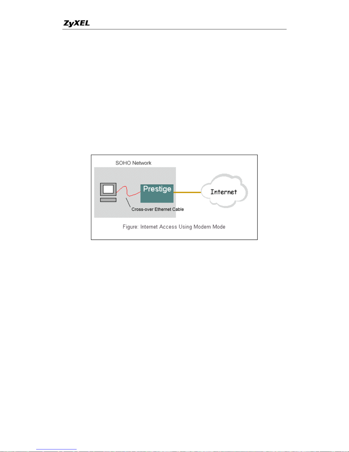
If the ISP limits some specific computers to access Internet, that means only the
traffic to/from these computers will be forwarded and the other will be filtered. In this
case, we use P-660 which works as an ADSL bridge modem to connect to the ISP.
The ISP will generally give one Internet account and limit only one computer to
access the Internet. See the figure below for this setup.
Set up your workstation
1. Ethernet connection
To connect your computer to the P-660's LAN port, the computer must have an
Ethernet adapter card installed. For connecting a single computer to the P-660, we
a cross-over Eth
use
ernet cable.
2. TCP/IP configuration
In most cases, the IP address of the computer is assigned by the ISP dynamically so
you have to configure the computer as a DHCP client which obtains the IP from the
ISP using DHCP protocol. The ISP may also provide the gateway, DNS via DHCP if
they are available. Otherwise, please enter the static IP addresses for all that the ISP
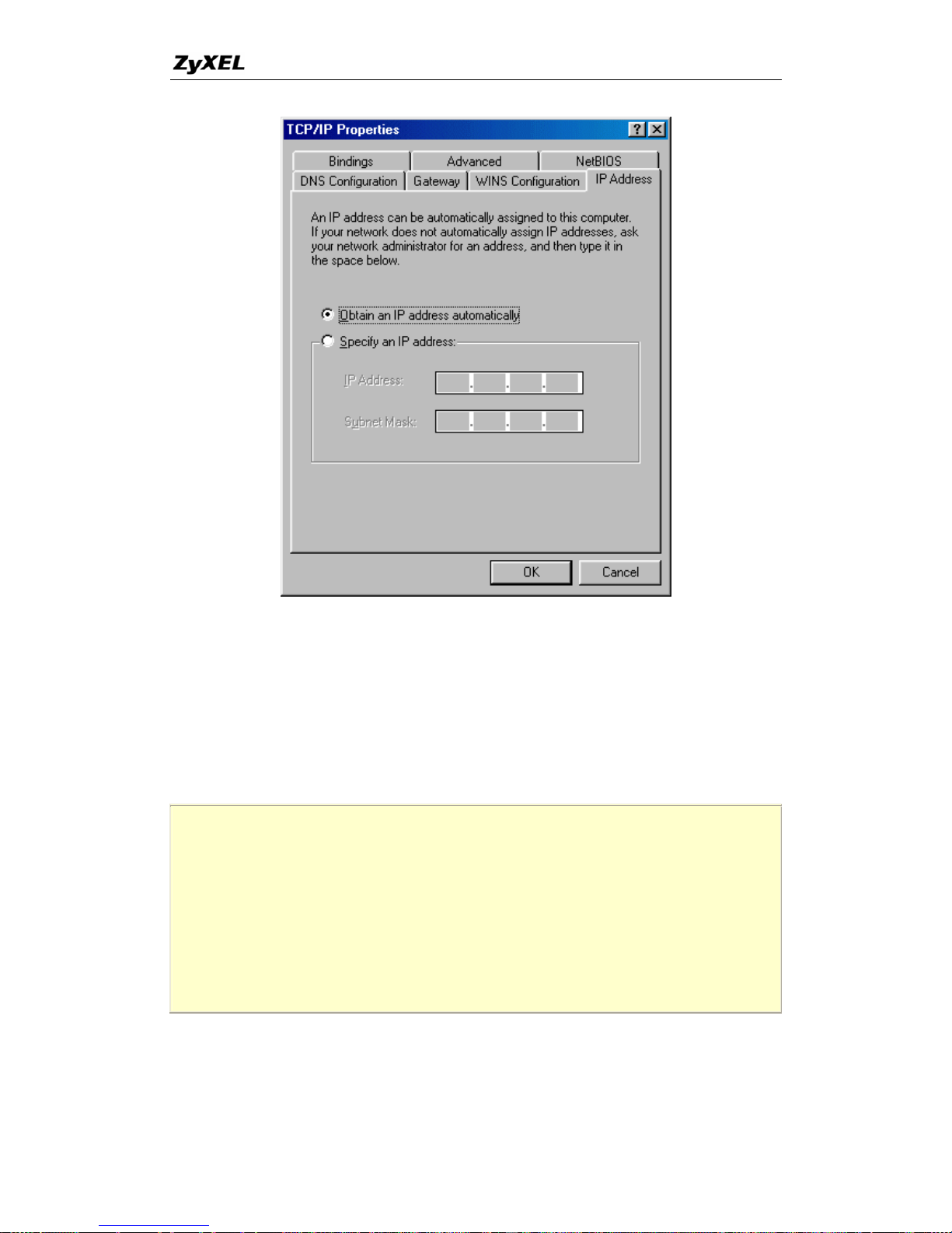
gives to you in the network TCP/IP settings. For Windows, we check the option
'Obtain an IP address automatically' in its TCP/IP setup, please see the example
shown below.
25
All contents copyright © 2005 ZyXEL Communications Corporation.
Page 27
P-660 series Support Notes
Setup your P-660 under bridge mode
The following procedure shows you how to configure your P-660 as an ADSL
Modem for bridging traffic. We will use SMT menu to guide you through the related
menu. You can use console or Telnet for finishing these configurations.
1. Configure P-660 as bridge mode in Menu 1 General Setup.
Menu 1 – General setup
System name=P-660
Location=
Contact Person's Name=
Domain Name=
Edit Dynamic DNS= No
Route IP= No
Bridge= Yes
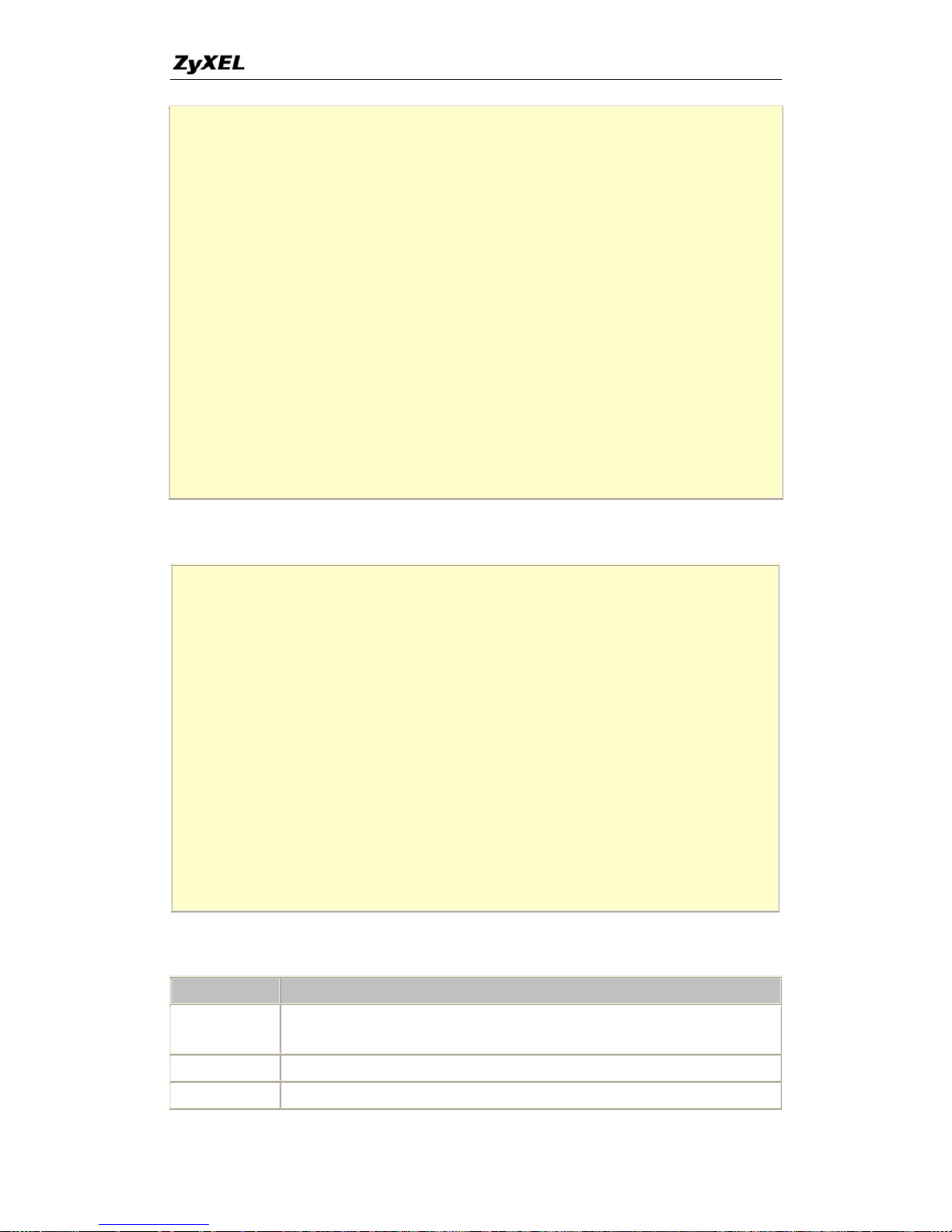
2. Configure a LAN IP for the P-660 and turn off DHCP Server in Menu 3.2-TCP/IP
Ethernet Setup. We use 192.168.1.1 in this case.
26
All contents copyright © 2005 ZyXEL Communications Corporation.
Page 28
P-660 series Support Notes
Menu 3.2 - TCP/IP and DHCP Setup
DHCP Setup
DHCP= None
Client IP Pool Starting Address= N/A
Size of Client IP Pool= N/A
Primary DNS Server= N/A
Secondary DNS Server= N/A
Remote DHCP Server= N/A
TCP/IP Setup:
IP Address= 192.168.1.1
IP Subnet Mask= 255.255.255.0
RIP Direction= None
Version= N/A
Multicast= None
IP Policies=
Edit IP Alias= No
3. Configure for Internet setup in Menu 11-Remote Node Profile.
Menu 11.1 - Remote Node Profile
Rem Node Name= Bridge Route= None
Active= Yes Bridge= Yes
Encapsulation= RFC 1483 Edit IP/Bridge= No
Multiplexing= LLC-based Edit ATM Options= No
Service Name= N/A Edit Advance Options= No
Incoming: Telco Option:
Rem Login= N/A Allocated Budget(min)= N/A
Rem Password= N/A Period(hr)= N/A
Outgoing: Schedule Sets= N/A
My Login= N/A Nailed-Up Connection= N/A
My Password= N/A Session Options:
Authen= N/A Edit Filter Sets= No
Idle Timeout(sec)= N/A
Key Settings:
Option Description
Encapsulation
Select the correct Encapsulation type that your ISP supports. For example, RFC
1483.
Multiplexing Select the correct Multiplexing type that your ISP supports. For example, LLC.
Router/ Bridge Disable routing mode and enable bridge mode, Bridge = Yes.
27
All contents copyright © 2005 ZyXEL Communications Corporation.
Page 29
P-660 series Support Notes
4. Configure ATM setting in Menu 11.6-Remote Node ATM Layer Options. In Menu
11.1, setup "Edit ATM Options= Yes" to enter Menu 11.6 sub-Menu.
Menu 11.6 - Remote Node ATM Layer Options
VPI #= 0
VCI #= 33
ATM QoS Type= CBR
Peak Cell Rate (PCR)= 0
Sustain Cell Rate (SCR)= 0
Maximum Burst Size (MBS)= 0
Key Settings:
Option Description
VPI & VCI
number
Specify a VPI (Virtual Path Identifier) and a VCI (Virtual Channel Identifier)
given to you by your ISP.
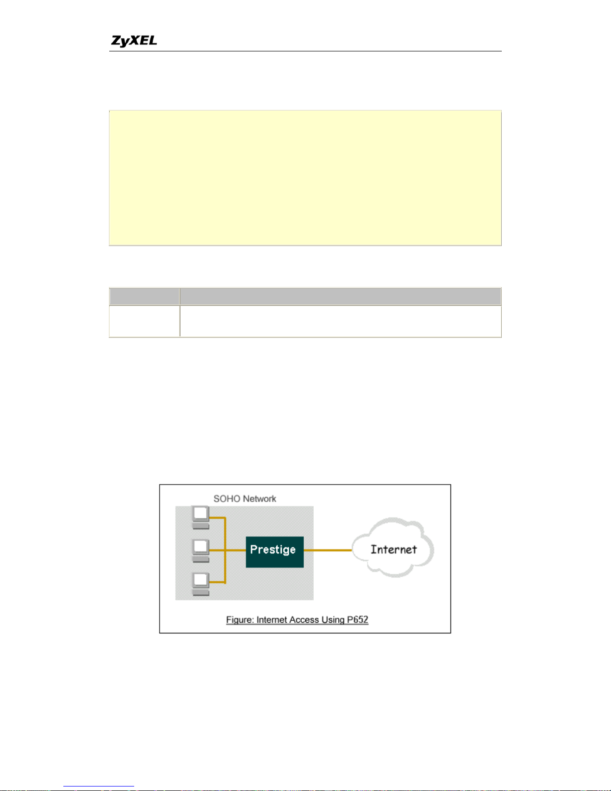
2. Internet Access Using P-660 under Router mode
For most Internet users having multiple computers want to share an Internet account
for Internet access, they have to install an Internet sharing device, like a router. In this
case, we use the P-660 which works as a general Router plus an ADSL
Modem. See the figure below for this setup.
Set up your workstation
1. Ethernet connection
28
All contents copyright © 2005 ZyXEL Communications Corporation.
Page 30
P-660 series Support Notes
Connect the LAN ports of all computers and the P-660 to a HUB using a straight
Ethernet cable.
2. TCP/IP configuration
Since the P-660 is set to DHCP server as default, so you need only to configure the
workstations as the DHCP clients in the networking settings. In this case, the IP
address of the computer is assigned by the P-660. The P-660 can also provide the
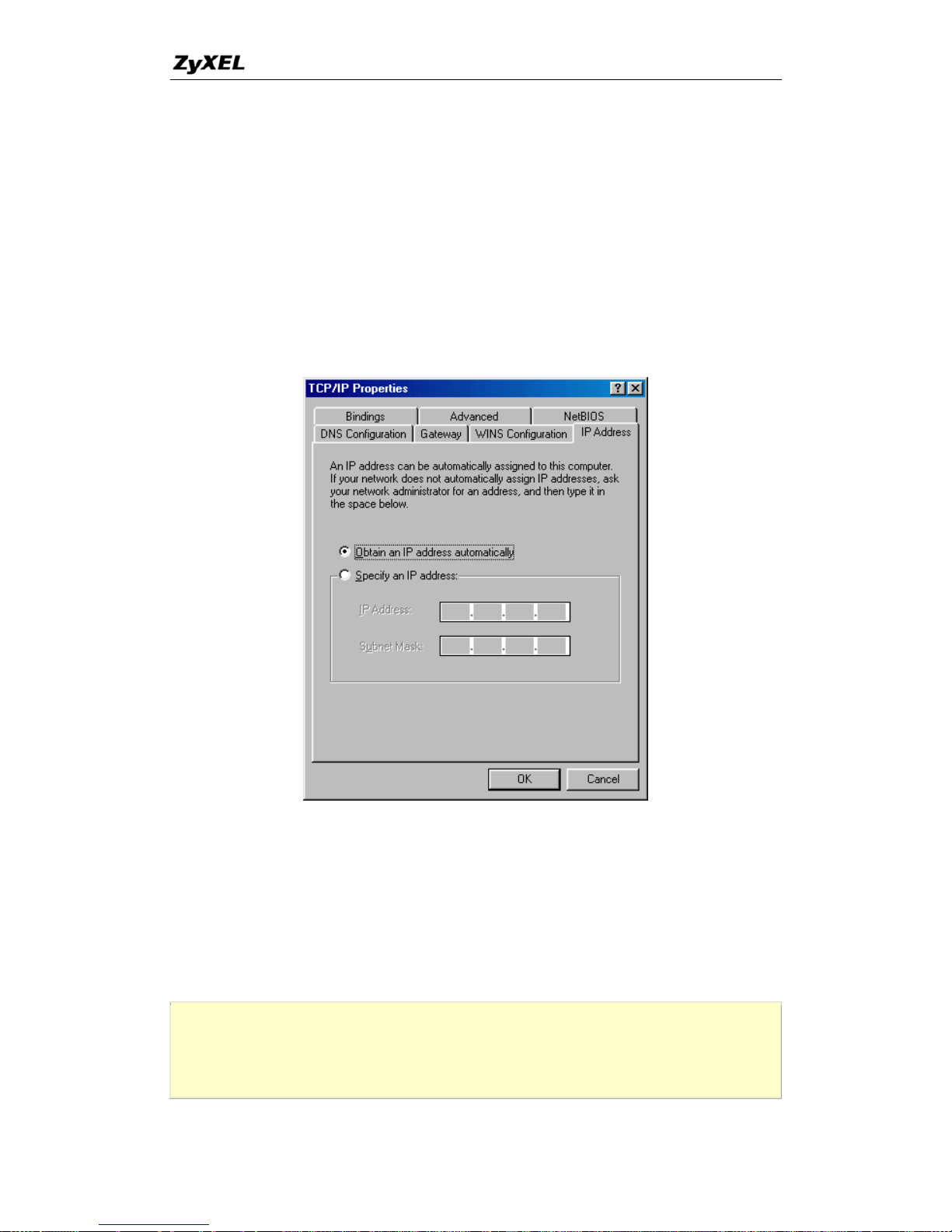
DNS to the clients via DHCP if it is available. For this setup in Windows, we check
the option 'Obtain an IP address automatically' in its TCP/IP setup. Please see the
example shown below.
S
The following procedure shows you how
routing traffic. We will use SMT menu to guide you th
can use console or Telnet for finishing these co
1. Configure P-660 as router mode in Menu 1
et up your P-660
to configure your P-660 as Router mode for
rough the related menu. You
nfigurations.
General Setup.
Menu 1– General Setup
System Name= P-660
Location=
29
All contents copyright © 2005 ZyXEL Communications Corporation.
Page 31

P-660 series Support Notes
Contact Person's Name=
Domain Name=
Edit Dynamic DNS= No
Route IP= Yes
Bridge= No
2. Configure a LAN IP for the P-660 and the DHCP
Ethernet Setup. The settings except of the DNS addresses sh
pre-configured defaults.
settings in Menu 3.2-TCP/IP
own below are the
Menu 3.2 - TCP/IP and DHCP Setup
DHCP Setup
DHCP= Server
Client IP Pool Starting Address= 192.168.1.33
Size of Client IP Pool= 6
Primary DNS Server= 168.95.1.1
Secondary DNS Server= 168.95.192.1
Remote DHCP Server= N/A
TCP/IP Setup:
IP Address= 192.168.1.1
IP Subnet Mask= 255.255.255.0
RIP Direction= Both
Version= RIP-1
Multicast= None
IP Policies=
Edit IP Alias= No
3. Configure for Internet setup in Menu 4-Internet Access Setup.
Menu 4 - Internet Access Setup
ISP's Name= CHT
Encapsulation= PPPoE
Multiplexing= LLC-based
VPI #= 0
VCI #= 33
ATM QoS Type= CBR
Peak Cell Rate (PCR)= 0
Sustain Cell Rate (SCR)= 0
Maximum Burst Size (MBS)= 0
My Login= [email protected]
30
All contents copyright © 2005 ZyXEL Communications Corporation.
Page 32
P-660 series Support Notes
My Password= ********
Idle Timeout (sec)= 0
Address Assignment= Dynamic IP
IP Address= N/A
Network Address Translation= SUA Only
Address Mapping Set= N/A
Press ENTER to Confirm or ESC to Cancel:
Key Settings:
Option Description
Encapsulation
Select the correct Encapsulation type that your ISP supports. For example,
RFC 1483.
Multiplexing
Select the correct Multiplexing type that your ISP supports. For example
LLC.
,
VPI & VCI Specify a VPI (Virtual Path entifier) and a VCI (Virtual Channel Identifier)
Id
number given to you by your ISP.
Single User
Set to Yes if you only have a single IP account for sharing with local
ers. Account comput
IP Address
Set to Dynamic if the ISP provides the IP for the P-660 dynamically.
.
Assignment
Otherwise, set to Static and enter the IP in the following IP Address field
IP Address
This field can not be configured if the ISP provides the IP for the P-660
dynamically. Otherwise, enter the IP that the ISP gives to you.
3. Setup the P-660 as a DHCP Relay
as
e LAN clients. When it is configured as
What is DHCP Relay?
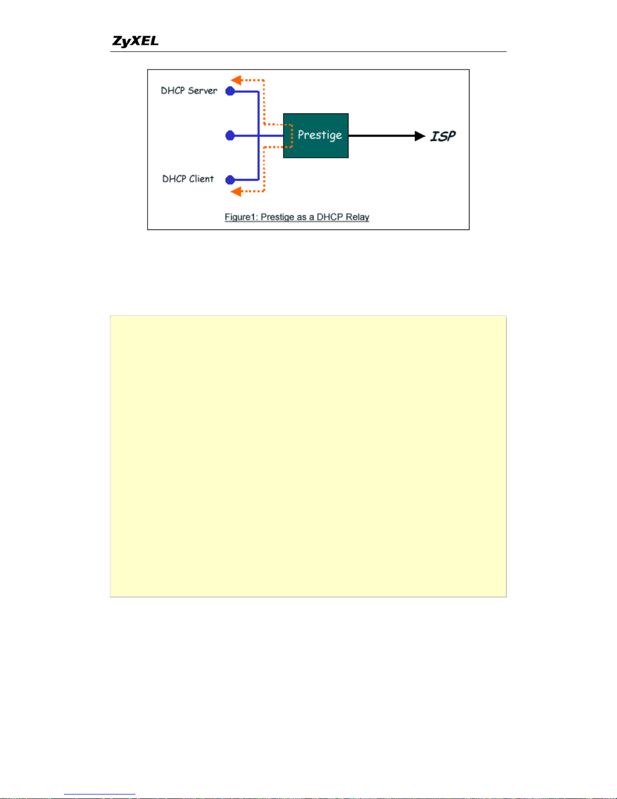
DHCP stands for Dynamic Host Configuration Protocol. In addition to the DHCP
server feature, the P-660 supports the DHCP relay function. When it is configured
DHCP server, it assigns the IP addresses to th
DHCP relay, it is responsible for forwarding the requests and responses negotiating
between the DHCP clients and the server. See figure 1.
31
All contents copyright © 2005 ZyXEL Communications Corporation.
Page 33
P-660 series Support Notes
Setup the P-660 as a DHCP Client
DHCP
rver in the 'Relay Server Address' field.
1. Toggle the DHCP to Relay in menu 3.2 and enter the IP address of the
se
Menu 3.2 - TCP/IP and DHCP Ethernet Setup
DHCP Setup
DHCP= Relay
Client IP Pool Starting Address= N/A
Size of Client IP Pool= N/A
Primary DNS Server= N/A
Secondary DNS Server= N/A
Relay Server Address= 192.168.1.2
TCP/IP Setup:
IP Address= 192.168.1.1
IP Subnet Mask= 255.255.255.0
RIP Direction= Both
Version= RIP-1
Multicast= None
IP Policies=
Edit IP Alias= No
Press ENTER to Confirm or ESC to Cancel:
4. SUA Notes
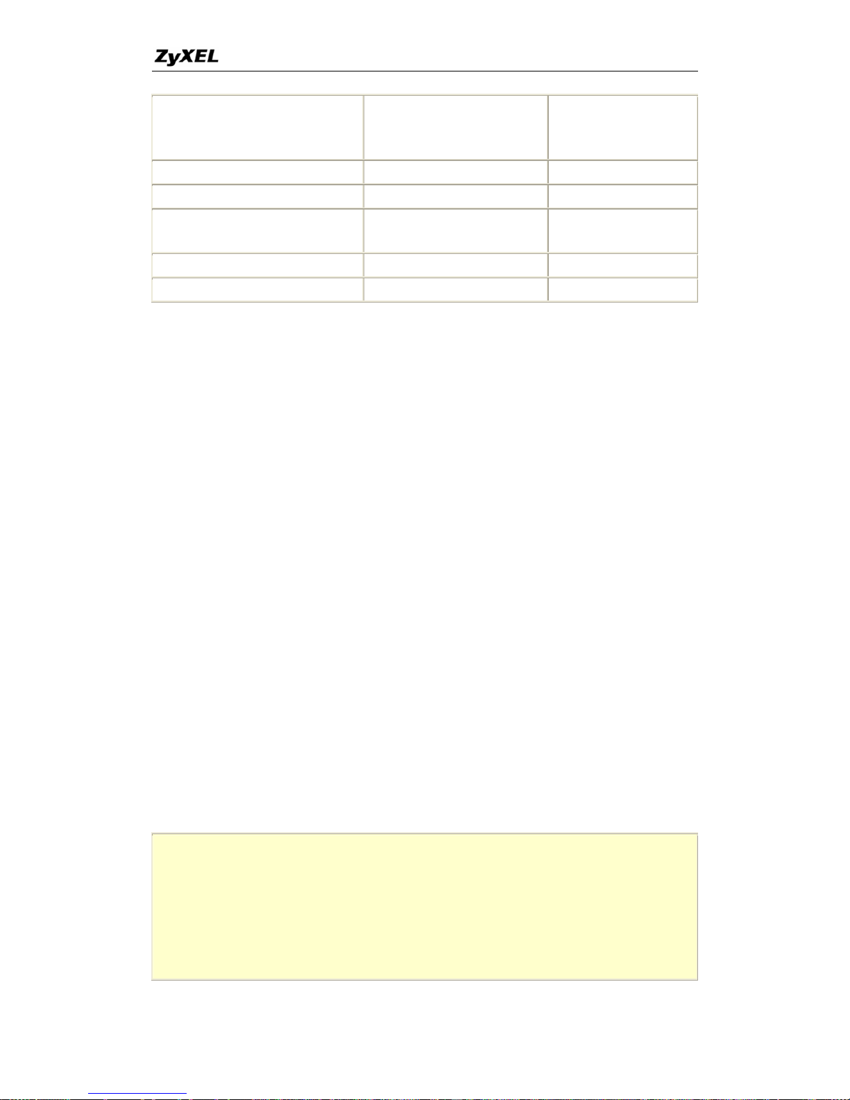
Tested SUA/NAT Applications (e.g., Cu-SeeMe, ICQ, NetMeeting)
32
All contents copyright © 2005 ZyXEL Communications Corporation.
Page 34
P-660 series Support Notes
Introduction
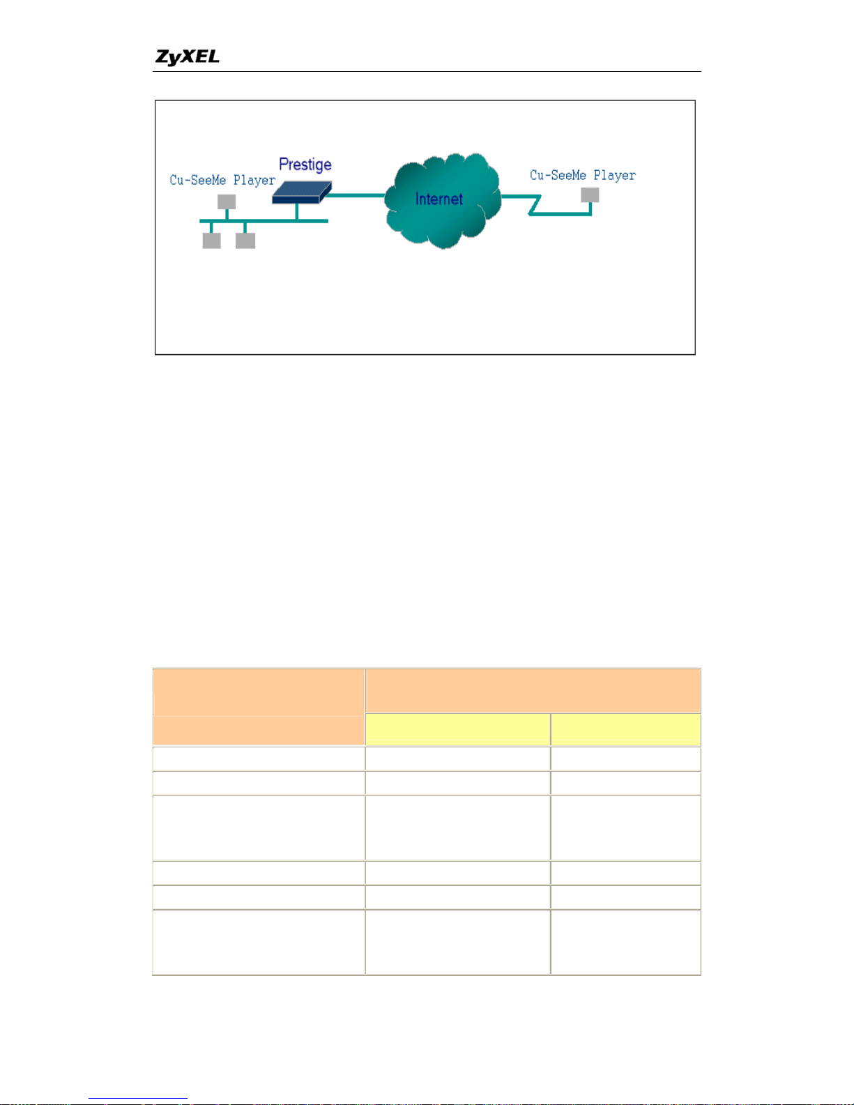
Generally, SUA makes your LAN machine to the outside world.
isible to outsid However, some appli
e, and ICQ will need to al user behi ch
case, a SUA server must be enter ward the incoming packets
to the true destination behind SUA t need extra settings of menu
15.2.1 for an outgoing connection e need to configure the
menu 15.2.1 to make the outgoing connection work. After the required menu 15.2.1
settings are completed the interna tions can be accessed by
using the P-660's
WAN IP addres
ting Table
he required me 2.1 settings for the var s
le
1
appear as a single
LAN users are inv e users. cations such as
Cu-SeeM connect to the loc
ed in menu 15.2.1 to for
. Generally, we do no
. But for some applications w
l server or client applica
s.
nd the P-660. In su
SUA Suppor
The following are t nu 15. ious application
running SUA mode.
ZyXEL SUA Supporting Tab
Required Settings in Menu 15.2.1
Port/IP
Application
Outgoing Connection Incoming Connection
HTTP None 80/client IP
FTP None 21/client IP
TELNET None 23(a/client IP
nd remove Telnet
ter in WAN port) fil
POP3 None 110/client IP
SMTP None 25/client IP
mIRC
None for Chat.
e set
t/Client IP
For DCC, pleas
Defaul
.
33
All contents copyright © 2005 ZyXEL Communications Corporation.
Page 35

P-660 series Support Notes
Windows PPTP None 1723/client IP
ICQ 99a None for Chat.
For DCC, please set:
connections -> firewall and
time out to
80 seconds in firewall
P
ICQ -> preference ->
set the firewall
setting.
Default/client I
ICQ 2000b None for Chat None for Chat
ICQ Phone 2000b None ient IP 6701/cl
Cornell 1.1 Cu-SeeMe None 7648/client IP
White Pine 3.1.2 Cu-SeeMe
2
7648/client IP &
client IP
P
24032/
Default/client I
White Pine 4.0 Cu-SeeMe lient IP & 7648/c
24032/client IP
Default/client IP
Microsoft NetMeeting 2.1 &
3.01
3
None 1720/client IP
1503/client IP
Cisco IP/TV 2.0.0 None .
RealPlayer G2 None .
VDOLive None .
Quake1.06
4
None Default/client IP
QuakeII2.30
5
None Default/client IP
QuakeIII1.05 beta None .
StartCraft. 6112/client IP .
Quick Time 4.0 None .
pcAnywhere 8.0 None
5631/client IP
5632/client IP
22/client IP
IPsec (ESP tunneling mode) None (one client only) Default/Client
Microsoft Messenger Service
3.0
6901/client IP 6901/client IP
Microsoft Messenger Service
None for Chat, Fil
4.6/ 4.7/ 5.0
6
transfer ,Video and Voic
(none UPnP)
Voice
None for Chat, File
e
e
transfer, Video and
Net2Phone None 6701/client IP
Network Time Protocol (NTP) None 123 /server IP
Win2k Terminal Server None 3389/server IP
Remote Anything None 3996 - 4000/client IP
34
All contents copyright © 2005 ZyXEL Communications Corporation.
Page 36
P-660 series Support Notes
00/client IP
Virtual Network Computing
(VNC)
None
5500/client IP
5800/client IP
59
AIM (AOL Instant Messenger) None for Chat and IM None for Chat and IM
e-Donkey None 4661 - 4662/client IP
POLYCOM Video
Conferencing
None Default/client IP
iVISTA 4.1 None 80/server IP
Microsoft Xbox Live7 None N/A
1
Since SUA enables your LAN to appear as a single computepr to the Internet, it is not
ossible to configure similar servers on the same LAN behind SUA.
Because White Pine Cu-SeeMe uses dedicate ports (port 7648 & port 24032) to
u-SeeMe is allowed within the
allowed because the outsiders can
same internet IP.
users to login using the same unique IP,
s case. Moreover, when a Quake server
ide information of that
video/ voice pass-through NAT since
ndows OS supported UPnP (Universal
, UPnP supported in P-660 is
n alternative solution to pass through MSN Messenger video/ voice traffic. For more
detail, please refer to UPnP application note.
new firmware version. If your P-660
firmware is too old to support such function, you may have a work-around solution,
please refer to ZyXEL website -> Support -> Xbox Live service
/support/xbox.htm
2
transmit and receive data, therefore only one local C
same LAN.
3
In SUA mode, only one local NetMeeting user is
not distinguish between local users using the
4
Certain Quake servers do not allow multiple
so only one Quake user will be allowed in thi
is configured behind SUA, P-660 will not be able to prov
server on the internet.
5
Quake II has the same limitations as that of Quake I.
6
P-660 support MSN Messenger 4.6/ 4.7/ 5.0
new firmware version. In addition, for the Wi
Plug and Play), such as Windows XP and Windows ME
a
7
P-660 support Microsoft Xbox Live since the
http://www.zyxel.com
Configurations
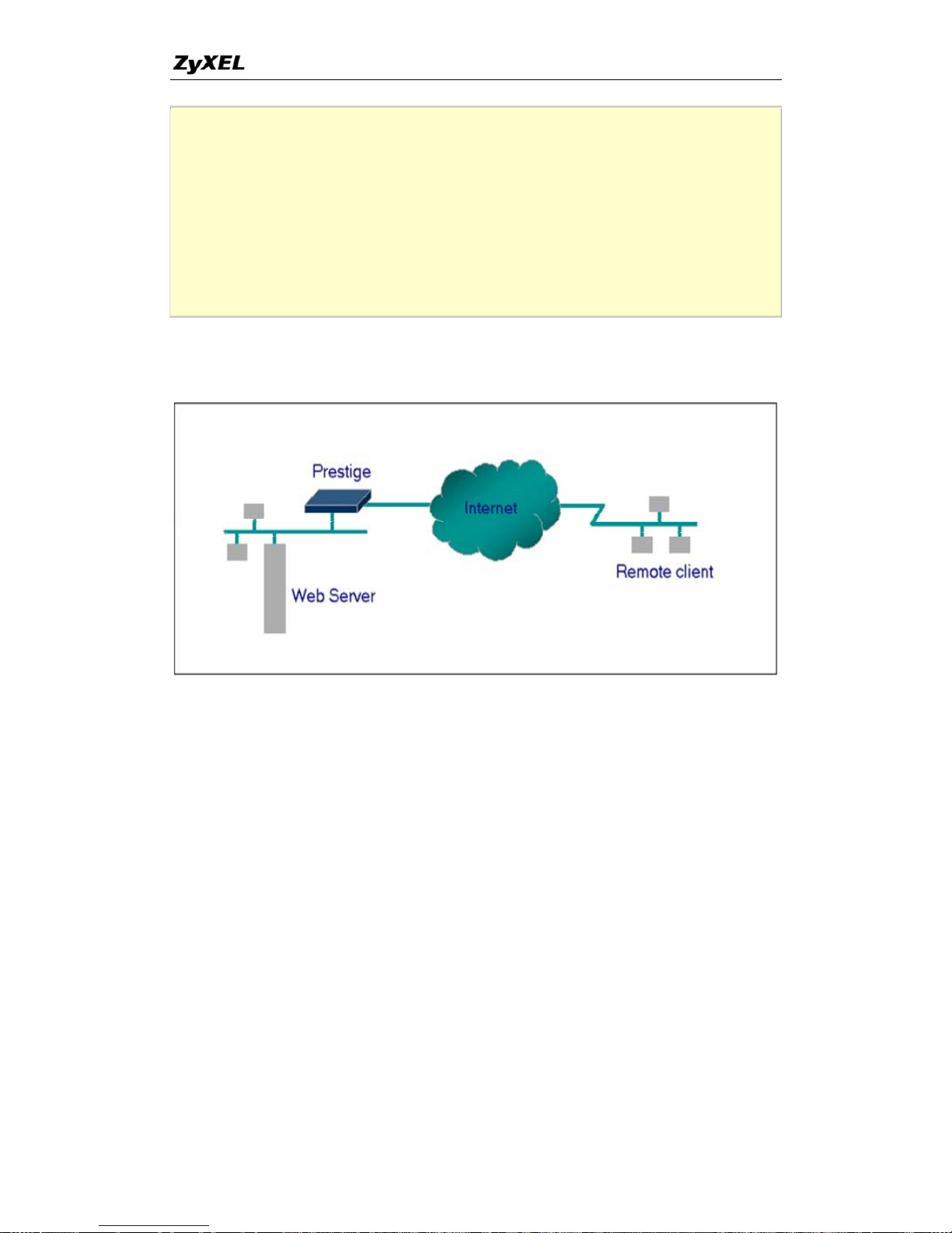
For example, if the workstation operating Cu-SeeMe has an IP of 192.168.1.34, then
the default SUA server must be set to 192.168.1.34. The peer Cu-SeeMe user can
reach this workstation by using P-660's
WAN IP address which can be obtained from
menu 24.1.
Menu 15.2.1 - NAT Server Setup (Used for SUA Only)
Rule Start Port No. End Port No. IP Address
---------------------------------------------- -----
1. Default Default 192.168.1.34
35
All contents copyright © 2005 ZyXEL Communications Corporation.
Page 37
P-660 series Support Notes
2. 0 0 0.0.0.0
3. 0 0 0.0.0.0
4. 0 0 0.0.0.0
5. 0 0 0.0.0.0
6. 0 0 0.0.0.0
7. 0 0 0.0.0.0
8. 0 0 0.0.0.0
9. 0 0 0.0.0.0
10. 0 0 0.0.0.0
Configure an Internal Server Behind SUA
Introduction
If you wish, you can make internal servers (e.g., Web
fo
th
, ftp or mail server) accessible
r outside users, even though SUA makes your LAN appear as a single machine to
e outside world. A service is identified by the port number. Also, since you need to
specify the IP address of a server in the P-660, a server must have a fixed IP address
and tially changes each time it is
powered on.
n to the servers for specific upports a default server. A
e request that does not have a s r explicitly designated for it is forwarded to
the default server. If the default server is not defined, the service request is simply
d.
ration
outsid orld, specify the port number of the service
and the inside address of the server in 'Menu 15.2.1', Multiple Server Configuration.
not be a DHCP client whose IP address poten
In additio services, SUA s
servic erve
discarde
Configu
To make a server visible to the e w
36
All contents copyright © 2005 ZyXEL Communications Corporation.
Page 38
P-660 series Support Notes
an access the local server using the P-660's WAN IP address
menu 24.1.
server for outside access) :
The outside users c
which can be obtained from
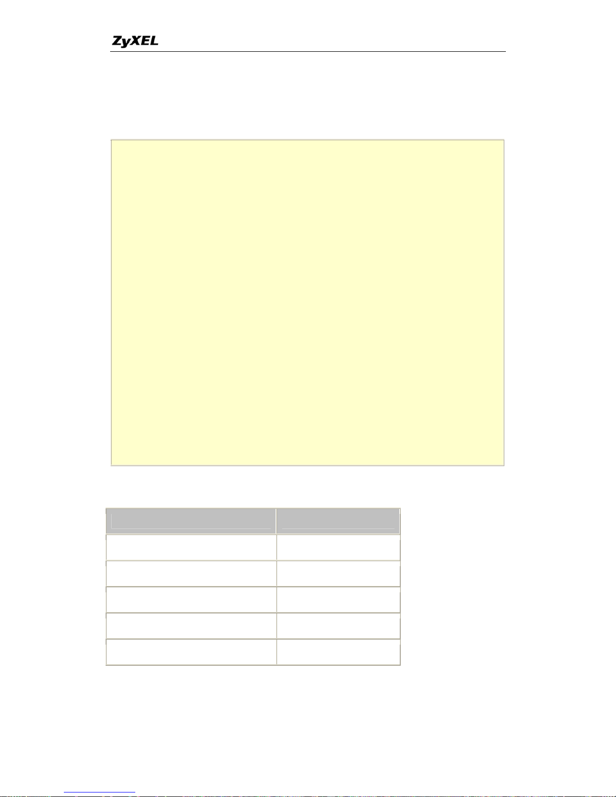
For example (Configuring an internal Web
Menu 15.2.1 - NAT Server Setup (Used for SUA Only)
Rule Start Port No. End Port No. IP Address
---------------------------------------------- -----
1. Default Default 0.0.0.0
2. 80 80 192.168.1.10
3. 0 0 0.0.0.0
4. 0 0 0.0.0.0
5. 0 0 0.0.0.0
6. 0 0 0.0.0.0
7. 0 0 0.0.0.0
8. 0 0 0.0.0.0
9. 0 0 0.0.0.0
10. 0 0 0.0.0.0
11. 0 0 0.0.0.0
12. 0 0 0.0.0.0
Press ENTER to Confirm or ESC to Cancel:
Port numbers for some services
Service Port Number
FTP 21
Telnet 23
SMTP 25
DNS (Domain Name Server) 53
www-http (Web) 80
Configure a PPTP server behind SUA
Introduction
37
All contents copyright © 2005 ZyXEL Communications Corporation.
Page 39
P-660 series Support Notes
o
ithin Internet Protocol (IP) packets and forwarded over any IP
network, including the Internet itself.
establish an IP
connection with a tunnel server such as the Windows NT Server 4.0 Remote Access
p
sed,
erved even across the
Internet.
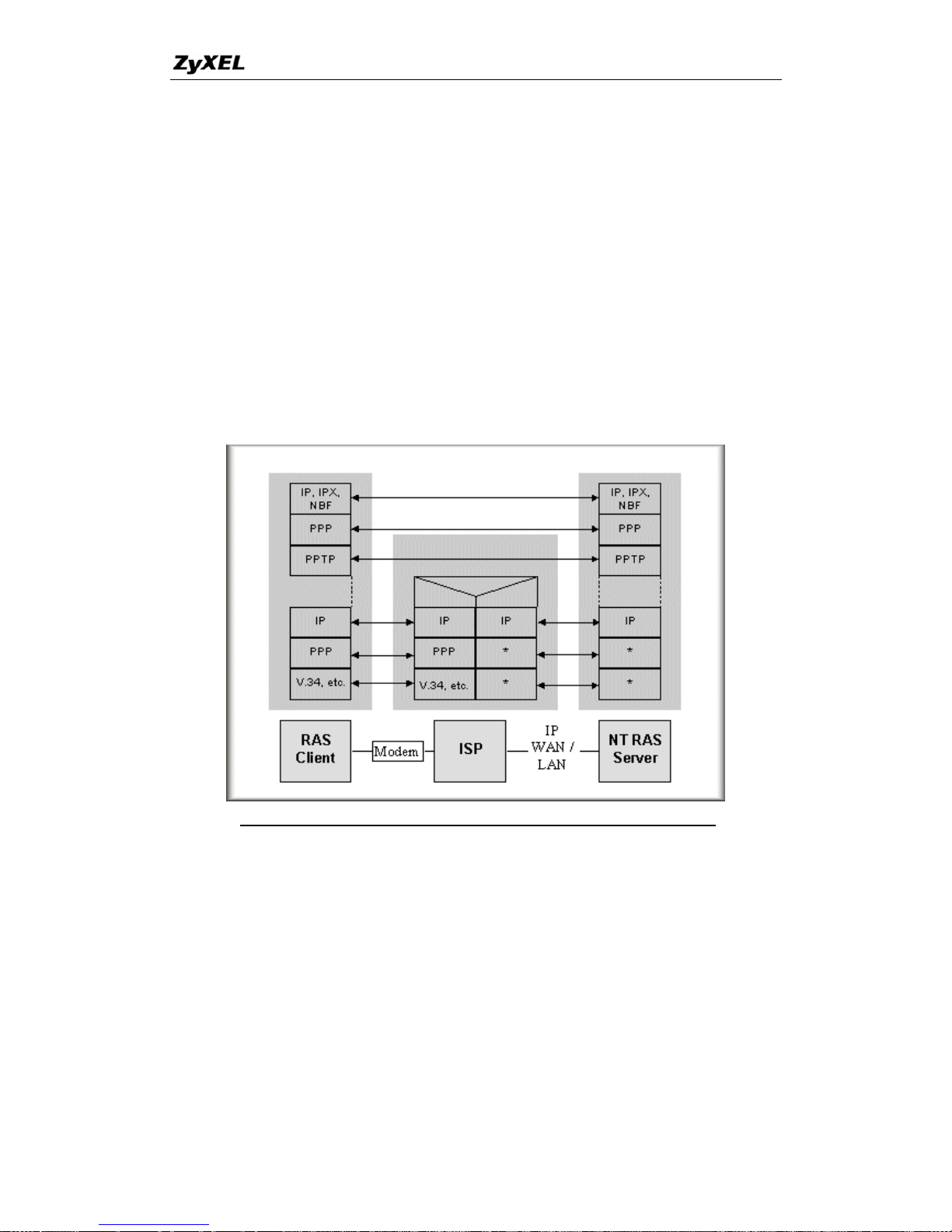
PPTP is a tunneling protocol defined by the PPTP forum that allows PPP packets t
be encapsulated w
In order to run the Windows 9x PPTP client, you must be able to
Server.
Windows Dial-Up Networking uses the Internet standard Point-to-Point (PPP) to
provide a secure, optimized multiple-protocol network connection over dial-u
telephone lines. All data sent over this connection can be encrypted and compres
and multiple network level protocols (TCP/IP, NetBEUI and IPX) can be run
correctly. Windows NT Domain Login level security is pres
Window98 PPTP Client / Internet / NT RAS Server Protocol Stack
ppears as new modem type (Virtual Private Networking Adapter) that can be PPTP a
sele . The VPN
Adapter type does not appear elsew
rotocol, the VPN requires a second dial-up adapter. This
second dial-up adapter for VPN is added during the installation phase of the Upgrade
in addition to the first dial-up adapter that provides PPP support for the analog or
ISDN modem.
The PPTP 98 already. For Windows 95, it
needs t e
cted when setting up a connection in the Dial-Up Networking folder
here in the system. Since PPTP encapsulates its
data stream in the PPP p
is supported in Windows NT and Windows
o b upgraded by the Dial-Up Networking 1.2 upgrade.
38
All contents copyright © 2005 ZyXEL Communications Corporation.
Page 40
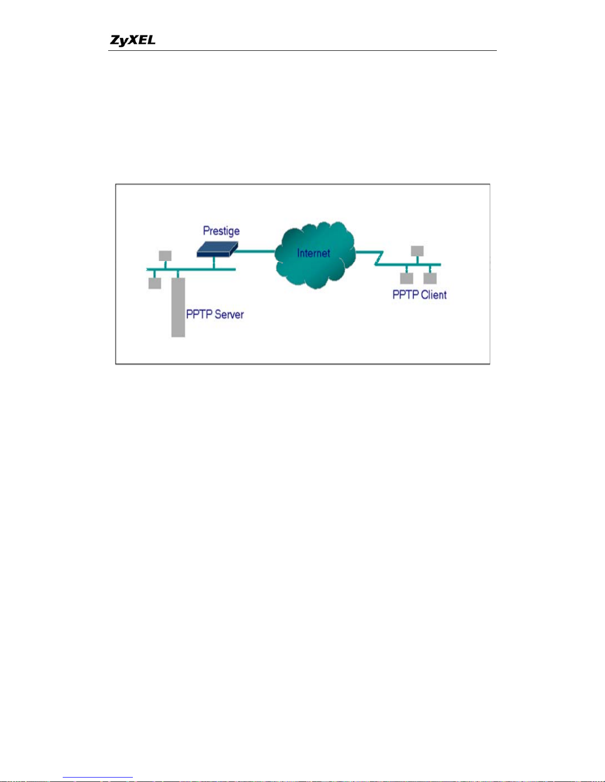
P-660 series Support Notes
his application note explains how to establish a PPTP connection with a remote
, all PPTP packets can be
The port
T Menu 15 for P-660 to forward to
NT server.
Configuration
T
private network in the P-660 SUA case. In ZyNOS
forwarded to the internal PPTP Server (WinNT server) behind SUA.
number of the PPTP has to be entered in the SM
the appropriate private IP address of Windows
Example
0.
1. PPTP server setup (WinNT)
• Add the VPN service from Control Panel>Network
t
s for
•
The following example shows how to dial to an ISP via the P-660 and then establish a
tunnel to a private network. There will be three items that you need to set up for PPTP
application, these are PPTP server (WinNT), PPTP client (Win9x) and the P-66
• Add an user account for PPTP logged on user
• Enable RAS port
• Select the network protocols from RAS such as IPX, TCP/IP NetBEUI
• Set the Internet gateway to P-660
2. PPTP client setup (Win9x)
• Add one VPN connection from Dial-Up Networking by entering the correc
username & password and the IP address of the P-660's Internet IP addres
logging to NT RAS server.
Set the Internet gateway to the router that is connecting to ISP
3. P-660 router setup
39
All contents copyright © 2005 ZyXEL Communications Corporation.
Page 41

P-660 series Support Notes
• Before making a VPN connection from Win9x to WinNT server, you need
to connect P-660 router to your ISP first.
• Enter the IP address of the PPTP server (WinNT server) and the port
number for PPTP as shown below.
ed.
N connection from the Win9x client to the NT server, you need to
net IP address that the ISP assigns to P-660 router in SUA mode
and enter this IP address in the VPN dial-up dialog box. You can check this Internet
Menu 15.2.1 - NAT Server Setup (Used for SUA Only)
Rule Start Port No. End Port No. IP Address
---------------------------------------------- -----
1. Default Default 0.0.0.0
2. 1723 1723 192.168.1.10
3. 0 0 0.0.0.0
4. 0 0 0.0.0.0
5. 0 0 0.0.0.0
6. 0 0 0.0.0.0
7. 0 0 0.0.0.0
8. 0 0 0.0.0.0
9. 0 0 0.0.0.0
10. 0 0 0.0.0.0
When you have finished the above settings, you can ping to the remote Win9x client
from WinNT. This ping command is used to demonstrate that remote the Win9x can
be reached across the Internet. If the Internet connection between two LANs is
achievable, you can place a VPN call from the remote Win9x client.
11. 0 0 0.0.0.0
12. 0 0 0.0.0.0
Press ENTER to Confirm or ESC to Cancel:
For example: C:\ping 203.66.113.2
When a dial-up connection to ISP is established, a default gateway is assigned to the
router traffic through that connection. Therefore, the output below shows the default
gateway of the Win9x client after the dial-up connection has been establish
Before making a VP
know the exact Inter
40
All contents copyright © 2005 ZyXEL Communications Corporation.
Page 42
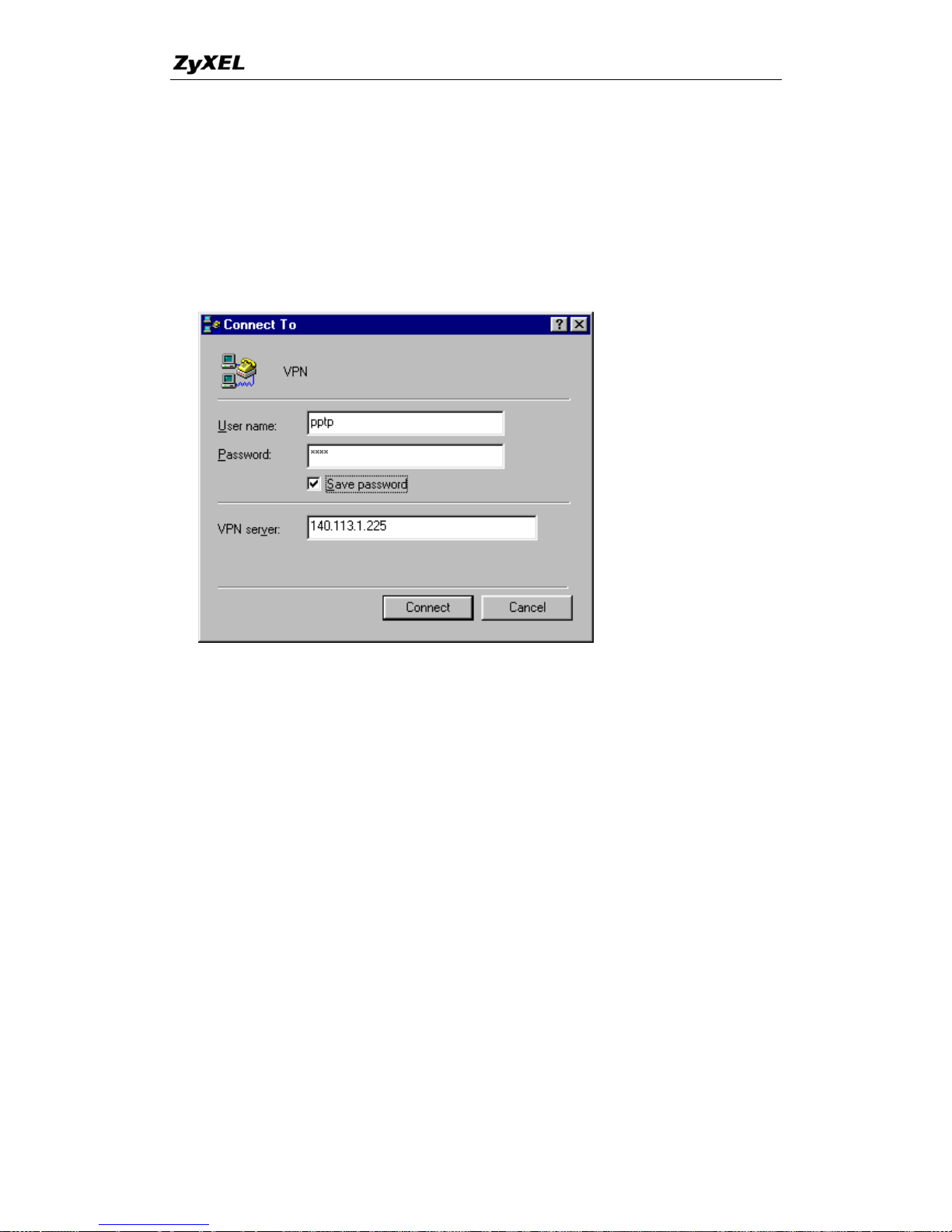
P-660 series Support Notes
y
IP address from PNC Monitor or SMT Menu 24.1. If the Internet IP address is a
fixed IP address provided by ISP in SUA mode, then you can always use this IP
address for reaching the VPN server.
In the following example, the IP address '140.113.1.225' is dynamically assigned b
ISP. You must enter this IP address in the 'VPN Server' dialog box for reaching the
PPTP server. After the VPN link is established, you can start the network protocol
application such as IP, IPX and NetBEUI.
5. Using Multi-NAT
What is Multi-NAT?
NAT (Network Address Translation-NAT RFC 1
Protocol address used within one
631) is the translation of an Internet
network to a different IP address known within
re
side IP addresses and "unmaps" the global IP addresses on incoming
ck into local IP addresses. The IP addresses for the NAT can be either fixed
it of
In such case, all incoming connections to your network will be
filtered out by the P-660, thus preventing intruders from probing your network.
tes by mapping the private
IP addresses to a global IP address. It is only one subset of the NAT. The P-660 with
0 support e features of the NAT based on RFC 1631, and
another network. One network is designated the inside network and the other is the
outside. Typically, a company maps its local inside network addresses to one or mo
global out
packets ba
or dynamically assigned by the ISP. In addition, you can designate servers, e.g., a web
server and a telnet server, on your local network and make them accessible to the
outside world. If you do not define any servers, NAT offers the additional benef
firewall protection.
The SUA feature that the P-660 supports previously opera
ZyNOS V3.4 s the most of th
41
All contents copyright © 2005 ZyXEL Communications Corporation.
Page 43
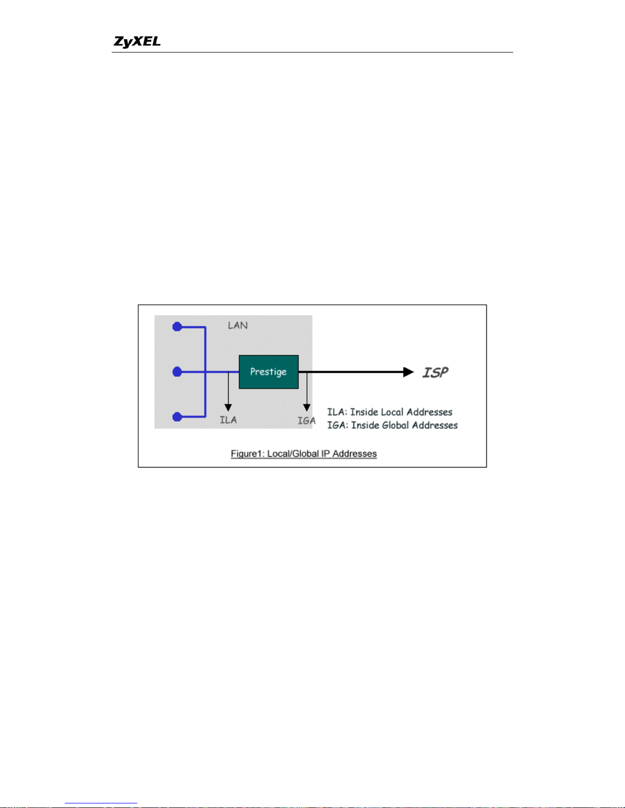
P-660 series Support Notes
ature as ' mo rmation on IP address translation,
please refer to RFC 163 Address Translator (NAT).
How NAT works
local IP nternal Local Addresses (ILA) and the
ddresses as t dd , see the following figure. The
term 'inside' refers to th
by mapping the ILA to the IGA required for communication with hosts on other
th address (and TCP or UDP source port
orw the Internet ISP, thus making them appear
come fro he P-660
the origi ort numbers so incoming reply packets can
we call this fe Multi-NAT'. For re info
1, The IP Network
If we define the
global IP a
addresses as the I
he Inside Global A
e set of networks that are subject to translation. NAT operates
ress (IGA)
networks. It replaces
numbers) and then f
as if they had
keeps track of
have their original values restored.
e original IP source
ards each packet to
m the NAT system itself (e.g., the P-660 router). T
nal addresses and p
NAT Mapping Types
NAT supports five types of IP/port mapping. They are:
One to One
In One-to-One mode, the P-660 maps one ILA to one IGA.
Many to One
In Many-to-One mode, the P-660 maps multiple ILA to one IGA. This is equivalent to
), ZyXEL's Single User Account feature that
previous ZyNOS routers supported (the SUA only option in today's routers).
any-to-Many Overload mode, the P-660 maps the multiple ILA to shared IGA.
SUA (i.e., PAT, port address translation
Many to Many Overload
In M
42
All contents copyright © 2005 ZyXEL Communications Corporation.
Page 44

P-660 series Support Notes
aps each ILA to unique IGA.
vers to one global IP address. This
ehind the NAT for outside
A please use the
Many to Many No Overload
In Many-to-Many No Overload mode, the P-660 m
Server
In Server mode, the P-660 maps multiple inside ser
allows us to specify multiple servers of different types b
access. Note, if you want to map each server to one unique IG
One-to-One mode.
The following table summarizes these types.
NAT Type IP Mapping
Mapping
Direction
One-to-One ILA1<--->IGA1 Both
Many-to-One
(SUA/PAT)
ILA1---->IGA1
ILA2---->IGA1 Outgoing
...
Many-to-Many
ILA2---->IGA2
Ov
...
erload
ILA1---->IGA1
ILA3---->IGA1
ILA4---->IGA2
Outgoing
Many-to-Many No
Overload
(Allocate by
Connections)
ILA2---->IGA3
ILA3---->IGA2
ILA4---->
...
Outgoing
ILA1---->IGA1
IGA4
Server
Server 1
IP<----IG
Server 2
A1
IP<----IGA1
Incoming
SUA Versus NAT
S
M
g
addresses, multiple severs of the same type (e.g., FTP serve
UA (Single User Account) in previous ZyNOS versions is a NAT set with 2 rules,
any-to-One and Server. The P-660 now has Full Feature NAT support to map
lobal IP addresses to local IP addresses of clients or servers. With multiple global IP
rs) are allowed on the
LAN for outside access. In previous ZyNOS versions (that supported SUA 'visible'
43
All contents copyright © 2005 ZyXEL Communications Corporation.
Page 45

P-660 series Support Notes
60
t in
e-configured, read only, Many-to-One mapping set,
sufficient for most purposes and helpful to people already familiar with SUA in
enus
Applying NAT in the SMT Menus
You apply NAT via men d 11.3 as
apply NAT for Internet access in menu 4 enu
4-Internet Access Setup.
servers had to be of different types. The P-660 supports NAT sets on a remote node
basis. They are reusable, but only one set is allowed for each remote node. The P-6
supports 8 sets since there are 8 remote node. The default SUA (Read Only) Se
menu 15.1 is a convenient, pr
previous ZyNOS versions.
SMT M
us 4 an displayed next. The next figure how you
. Enter 4 from the Main Menu to go to M
Menu 4 - Internet Access Setup
me= ISP's Na CHT
Encapsulation= PPPoE
Multiplexing= LLC-based
VPI #= 0
VCI #= 33
ATM QoS T R ype= CB
Peak Cell Rate (PCR)= 0
Sustain Cell Rate (SCR)= 0
Maximum Burst Size (MBS)= 0
My Login= [email protected]
My Password= ********
Idle Timeout (sec)= 0
IP Address Assignment= Static
IP Address= 200.1.2.1
Network Address Translation= Full Feature
Address Mapping Set= 1
Press ENTER to Confirm or ESC to Cancel:
The following figure shows how you apply NAT to the remote node in menu 11.3.
Menu 11.3 - Remote Node Network Layer Options
IP Options: Bridge Options:
IP Address Assignment = Dynamic
44
All contents copyright © 2005 ZyXEL Communications Corporation.
Page 46

P-660 series Support Notes
Rem IP Addr = 0.0.0.0
Rem Subnet Mask= 0.0.0.0
My WAN Addr= N/A
NAT= Full Feature
Address Mapping Set= 1
Metric= 2
Private= No
RIP Direction= None
Version= RIP-1
Multicast= None
IP Policies=
Enter here to CONFIRM or ESC to CANCEL:
Step 1. Enter 11
Step 2. Move th
default No to Y
Network Laye
The following t
from the Main Menu.
e cursor to the Edit IP field, press the [SPACEBAR] to toggle the
es, then press [ENTER] to bring up Menu 11.3-Remote Node
r Options.
able describes the options for Network Address Translation.
Field Options Description
Full Feature
When you select this option the SMT will use
Address Mapping Set 1 (Menu 15.1-see later for
further discussion).
None
NAT is disabled when you select this option.
Network Address
Translation
SUA Only
e
Address Mapping Set 255 (Menu 15.1-see later for
further discussion). This option use basically
Many-to-One Overload mapping. Select Full
Feature when you require other mapping types. It
is a convenient, pre-configured, read only,
e mapping set, sufficient for most
purposes and helpful to people already familiar
with SUA in previous ZyNOS versions. Note that
there is also a Server type whose IGA is 0.0.0.0 in
When you select this option the SMT will us
Many-to-On
this set.
Table: Applying NAT in Menu 4 and Menu 11.3
45
All contents copyright © 2005 ZyXEL Communications Corporation.
Page 47

P-660 series Support Notes
guring NAT
nfigure NAT, enter 15 from the Main Menu to bring up the following screen.
Confi
To co
Menu 15 - NAT Setup
1. Address Mapping Sets
2. NAT Server Sets
Address Ma
d us to create th le used
ssign global addresses to LAN clients. Each remote node must specify which NAT
Address Ma so allows you to
in Menu 15.1. You can only configure from Set 1 to Set 8. Set 255 is used for SUA.
r correct NAT Set as
ll. When t 255.
apped to external ports. To use
-660), a server rule must be set up inside the NAT Address
ing se for further information
pping Sets and NAT Server Sets
Use the Ad
to a
ress Mapping Sets menus and submen e mapping tab
pping Set to use. The P-660 has 8 remote nodes and
NAT Address Mapping Set. You can see nine NAT Address Mapping sets configure 8
When you sweelect Full Feature in menu 4 or 11.3, you must ente
you select SUA Only, the SMT will use Se
The NAT S
this set (one set for the P
erver Set is a list of LAN side servers m
Mapp t. Please see NAT Server Sets on these menus.
Enter 1 to bring up Menu 15.1-Address Mapping Sets
Me nu 15.1 - Address Mapping Sets
1.
2.
3.
4.
5.
6.
7.
8.
255. SUA (Read Only)
Enter Set Number to Edit:
46
All contents copyright © 2005 ZyXEL Communications Corporation.
Page 48
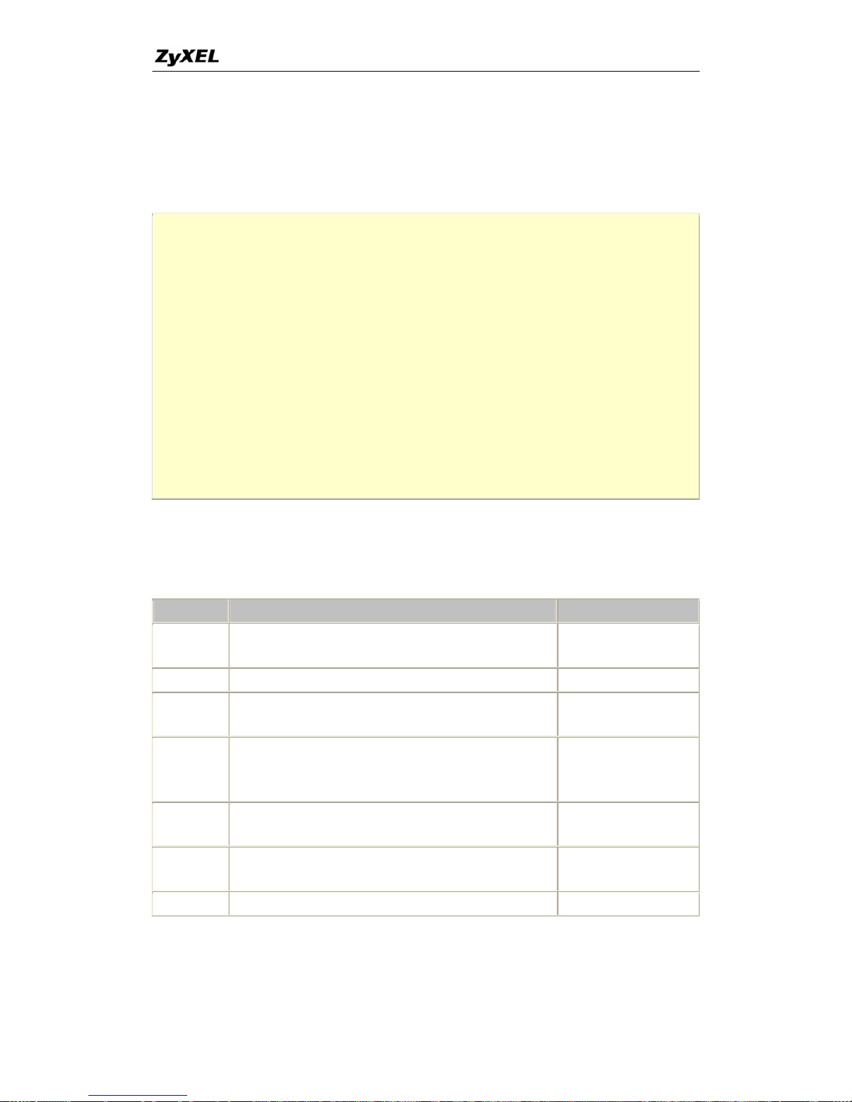
P-660 series Support Notes
irst look at Option 255. Option 255 is equivalent to SUA in previous ZyXEL
The fields in this menu cannot be changed. Entering 255 brings up this
Let's f
routers.
screen.
Menu 15.1.255 - Address Mapping Rules
Set Name= SUA (Read Only)
Idx Local Start IP Local End IP Global Start IP Global End IP Type
--- --------------- --------------- --------------- --------------- ---- --
1. 0.0.0.0 255.255 0.0.0.0 M-1 255.255.
2. 0.0.0.0 Serve+
3.
4.
5.
6.
The follow fields in this
menu are r
ing table explains the fields in this screen. Please note that the
ead-only.
Field Description Option/Example
Set Name
u selected in Menu 15.1 or
enter the name of a new set you want to create.
SUA
This is the name of the set yo
Idx This is the index or rule number. 1
Local Start
IP
This is the starting local IP address (ILA).
0.0.0.0 for the
Many-to-One type.
Local End IP all local IPs, then the Start IP is 0.0.0.0 and the End IP is
255.255.255.255.
255.255.255.255
This is the starting local IP address (ILA). If the rule is for
Global Start
IP
This is the starting global IP address (IGA). If you have a
0.0.0.0
dynamic IP, enter 0.0.0.0 as the Global Start IP.
Global End
This is the ending global IP address (IGA). N/A
IP
Type This is the NAT mapping types. Many-to-One and Server
Please note that the fields in this m
server set 1 can be modifi
enu are read-only. However, the settings of the
ed in menu 15.2.1.
47
All contents copyright © 2005 ZyXEL Communications Corporation.
Page 49

P-660 series Support Notes
1 in Menu 15.1. Enter 1 to bring up this menu. Now let's look at Option
Menu 15.1.1 - Address Mapping Rules
Set Name= ?
Idx Local Start IP Local End IP Global Start IP Global End IP Type
--- --------------- --------------- --------------- --------------- ---- --
1.
2.
3.
4.
5.
6.
7.
8.
9.
10.
Action= Edit , Select Rule= 0
Press ENTER to Confirm or ESC to Cancel:
We will ju te that, this screen is
not re No that the [?] in
d you mu r a name for
e set. Th The Type, Local and
Glob l values
are displayed here.
st look at the differences from the previous menu. No
ad on
t Nam
ly, so we have extra Action and Select Rule fields.
e field means that this is a required field an
t also
st entethe Se
th e description of the other fields is as described above.
rt/End IPs are configured in Menu 15.1.1 (describedal Sta ater) and the
Field Description Option
Set Name
note that
Enter a name for this set of rules. This is a required field. Please
if this field is left blank, the entire set will be deleted.
Rule1
Action
They are 4 actions. The default is Edit. Edit means you want to edit
a selected rule (see following field). Insert Before means to insert a
new rule before the rule selected. The rule after the selected rule will
then be moved down by one rule. Delete means to delete the
selected rule and then all the rules after the selected one will be
advanced one rule. Save Set means to save the whole set (note w
Edit
Insert Before
Delete
hen
Save Set
you choose this action the Select Rule item will be disabled).
Select Rule
When you choose Edit, Insert Before or Save Set in the previous
field the cursor jumps to this field to allow you to select the rule to
apply th1 e action in question.
Note: Save Set in the Action field means to save the whole set. You must do this if
you make any changes to the set-including deleting a rule. No changes to the set take
48
All contents copyright © 2005 ZyXEL Communications Corporation.
Page 50
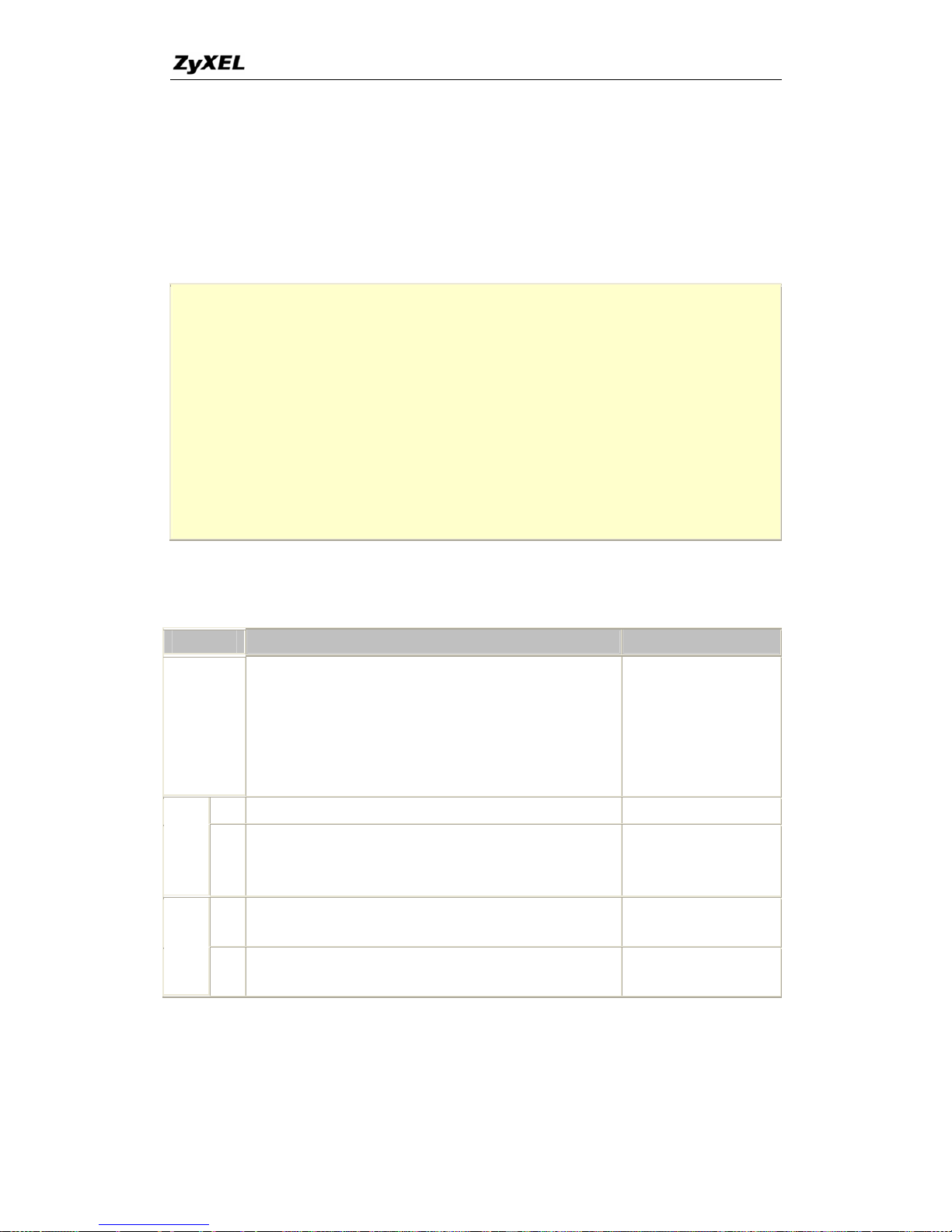
P-660 series Support Notes
place until this action is taken. Be careful when ordering your rules as each rule is
executed in turn beginning from the first rule.
Selecting Edit in the Action field and then selecting a rule brings up the following
menu, Menu 15.1.1.1-Address Mapping Rule in which you can edit an individual
rule and configure the Type, Local and Global Start/End IPs displayed in Menu
15.1.1.
Menu 15.1.1.1 - - Rule 1
Type: One-to-One
Local IP:
Start= 0.0.0.0
End = N/A
Global IP:
Start= 0.0.0.0
End = N/A
Press ENTER to Confirm or ESC to Cancel:
The following table describes the fields in this screen.
Field Description Option/Example
Type
Press [SPACEBAR] to toggle through a total o
These are the mapping types discussed abo
type. Some examples follow to clarify
f 5 types.
ve plus a server
these a little more.
One-to-One
Many-to-One
Many-to-Many Overload
Many-to-Many No
Overload
Server
Start This is the starting local IP address (ILA) 0.0.0.0
L
I
s (ILA). If the rule is for
as 0.0.0.0 and the End IP
N/A for One-to-One type.
255.255.255.255
ocal
P
End
This is the ending local IP addres
all local IPs, then put the Start IP
as 255.255.255.255. This field is
Start
This is the starting global IP addr
dynamic IP, enter 0.0.0.0 as the G
ess (IGA). If you have a
lobal Start IP.
0.0.0.0
G
I
dress (IGA). This
field
-One and Server types.
200.1.1.64
lobal
P
End
This is the ending global IP ad
is N/A for One-to-One, Many-to
Note: For all Local and Global IPs, the End IP address must begin after the IP Start
nning before the Start IP address. address, i.e., you cannot have an End IP address begi
49
All contents copyright © 2005 ZyXEL Communications Corporation.
Page 51
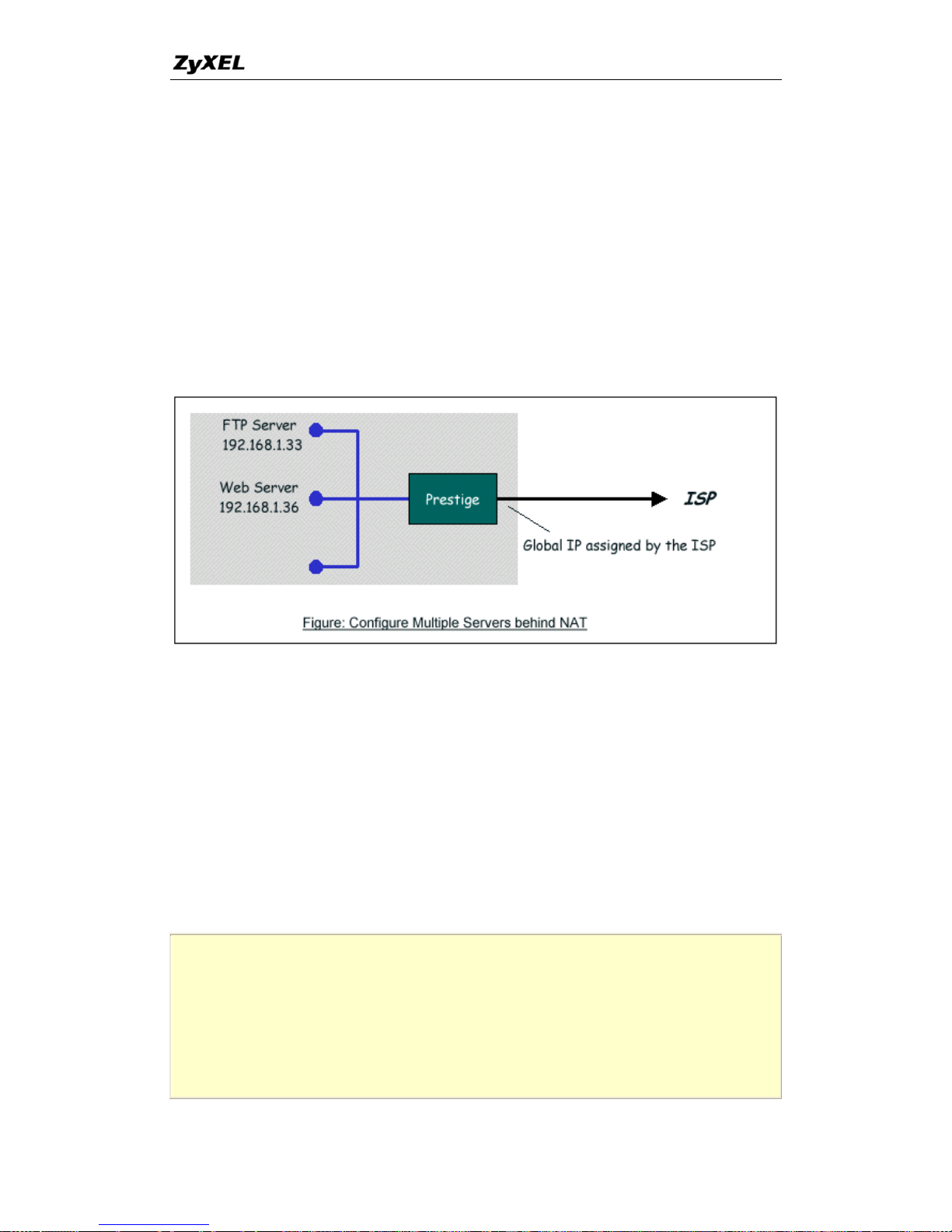
P-660 series Support Notes
NAT Server Set is a list of LAN side servers mapped to external ports (similar to
the old SUA menu of before). If you wish, you can make inside servers for different
e.g., Web or FTP, visible to s, even though NAT makes your
rk appears as a single machine to the outside world. A server is identified by the
ber, e.g., Web service is on port 80 and FTP on port 21.
ample (see the following fig eb server at 192.168.1.36
.33, the u need to specify for port 80 (Web) the
s 192.168.1.36 and port 21 (FTP) another at IP address
NAT Server Sets
The
services, the outside user
netwo
port num
As an ex ure), if you have a W
and a FTP server at 192.168.1 n yo
server at IP addres for
192.168.1.33.
Please note that a server can support more than one service, e.g., a server can provide
both FTP and Mail service, while another provides only Web service.
The following procedures show how to configure a server behind NAT.
Step 1. Enter 15 in the Main Menu to go to Menu 15-NAT Setup.
tep 2. Enter 2 to go to Menu 15.2.1-NAT Server Setup.
the inside IP address of
field.
R to confirm...' prompt to save your
ss ESC at any time to cancel.
S
Step 3. Enter the service port number in the Port# field and
the server in the IP Address
Step 4. Press [SPACEBAR] at the 'Press ENTE
configuration after you define all the servers or pre
Menu 15.2.1 - NAT Server Setu p (Used for SUA Only)
Rule Start Port No. End Port No. IP Address
---------------------------------------------- -----
1. Default Default 0.0.0.0
2. 21 21 192.168.1.33
3. 80 80 192.168.1.36
50
All contents copyright © 2005 ZyXEL Communications Corporation.
Page 52
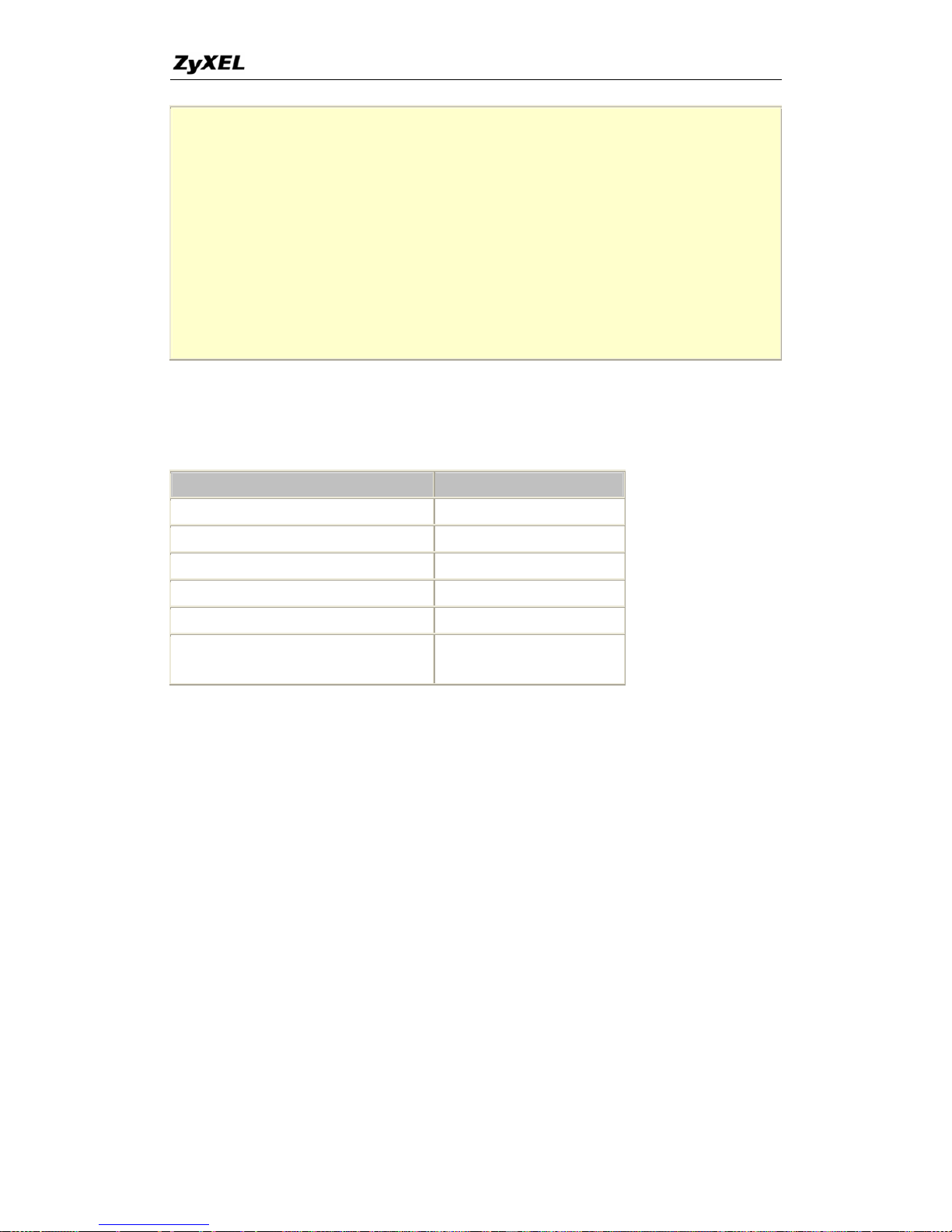
P-660 series Support Notes
4. 0 0 0.0.0.0
5. 0 0 0.0.0.0
6. 0 0 0.0.0.0
7. 0 0 0.0.0.0
8. 0 0 0.0.0.0
9. 0 0 0.0.0.0
10. 0 0 0.0.0.0
11. 0 0 0.0.0.0
12. 0 0 0.0.0.0
Press ENTER to Confirm or ESC to Cancel:
The most often used port numbers are shown in the following table. Please refer RFC
1700 for further information about port numbers.
Service Port Number
FTP 21
Telnet 23
SMTP 25
DNS (Domain Name Server) 53
www-http (Web) 80
PPTP (Point-to-Point Tunneling
Protocol)
1723
Examples
• Internet Access Only
• Internet Access with an Internal Server
ap to one
• Using Multiple Global IP addresses for clients and servers
• Support Non NAT Friendly Applications
1. Internet Access Only
In our Internet Access example, we only need one rule where all our ILAs m
IGA assigned by the ISP. See the following figure.
51
All contents copyright © 2005 ZyXEL Communications Corporation.
Page 53
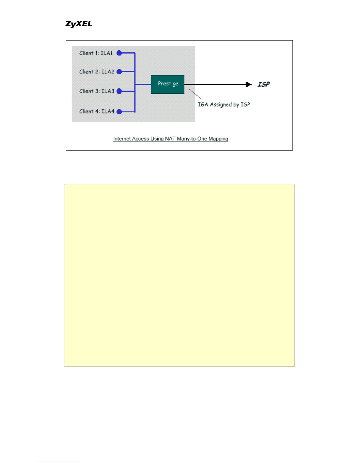
P-660 series Support Notes
Menu 4 - Internet Access Setup
ISP's Name= CHT
Encapsulation= PPPoE
Multiplexing= LLC-based
VPI #= 0
VCI #= 33
ATM QoS Type= CBR
Peak Cell Rate (PCR)= 0
Sustain Cell Rate (SCR)= 0
Maximum Burst Size (MBS)= 0
My Login= [email protected]
My Password= ********
Idle Timeout (sec)= 0
IP Address Assignment= Dynamic
IP Address= N/A
Network Address Translation= SUA Only
Address Mapping Set= N/A
Press ENTER to Confirm or ESC to Cancel :
From Menu 4 shown above simply choose the SUA Only option from the NAT field.
his is the Many-to-One mapping discussed earlier. The SUA read only option from
e NAT field in menu 4 and 11.3 is specifically pre-configured to handle this case.
T
th
52
All contents copyright © 2005 ZyXEL Communications Corporation.
Page 54
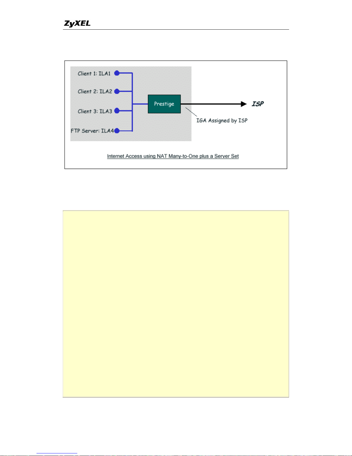
P-660 series Support Notes
. Internet Access with an Internal Server 2
In this case, we do exactly as above (use the co
and also go to Menu 15.2.1-NAT Server Setup (Used for SUA Only
Internet Server behind the NAT as shown in the NAT
nvenient pre-configured SUA Only set)
) to specify the
as shown below.
Menu 15.2.1 - NAT Server Setup (Used for SUA Only)
Rule Start Port No. End Port No. IP Address
---------------------------------------------- -----
1. Default Default 0.0.0.0
2. 21 21 192.168.1.33
3. 0 0 0.0.0.0
4. 0 0 0.0.0.0
5. 0 0 0.0.0.0
6. 0 0 0.0.0.0
7. 0 0 0.0.0.0
8. 0 0 0.0.0.0
9. 0 0 0.0.0.0
10. 0 0 0.0.0.0
11. 0 0 0.0.0.0
12. 0 0 0.0.0.0
Press ENTER to Confirm or ESC to Cancel:
53
All contents copyright © 2005 ZyXEL Communications Corporation.
Page 55
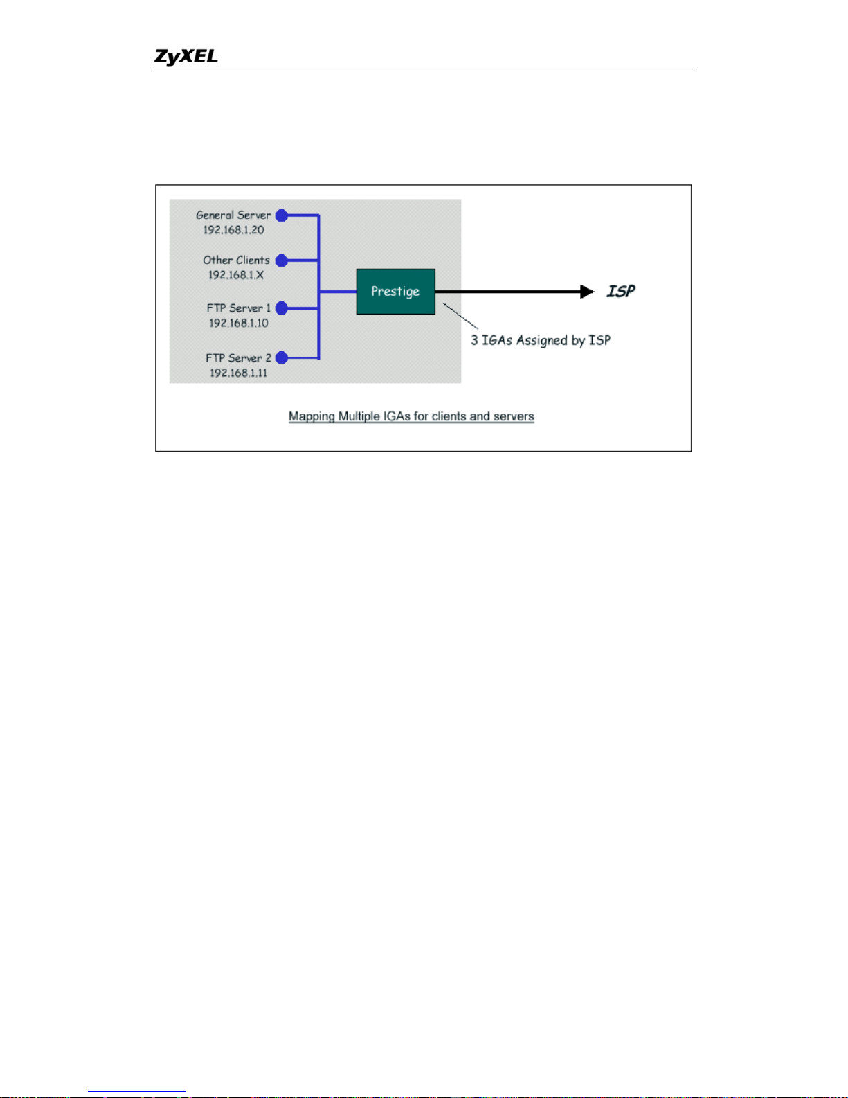
P-660 series Support Notes
o-One,
Many-to-One, Server Set mapping types are used)
3. Using Multiple Global IP addresses for clients and servers (One-t
In this case we have 3 IGAs (IGA1, IGA2 and IGA3) from the ISP. We have two very
busy internal FTP servers and also an internal general server for the web and mail. In
is case, we want to assign the 3 IGAs by the following way using 4 NAT rules.
• Rule 1 (One-to-One type) to map the FTP Server 1 with ILA1 (192.168.1.10)
• Rule 2 (One-to-One type) to map the FTP Server 2 with ILA2 (192.168.1.11)
e type) to map the other clients to IGA3.
web server and mail server with ILA3
Server allows us to specify multiple servers, of
achines behind NAT on the LAN.
In this case, we need to configure Address Mapping Set 1 from Menu 15.1-Address
eature option from the NAT
eld in menu 4 or menu 11.3, and assign IGA3 to P-660 WAN IP Address.
th
to IGA1.
to IGA2.
• Rule 3 (Many-to-On
• Rule 4 (Server type) to map a
(192.168.1.20) to IGA3. Type
different types, to other m
Step 1:
Mapping Sets. Therefore we must choose the Full F
fi
54
All contents copyright © 2005 ZyXEL Communications Corporation.
Page 56

P-660 series Support Notes
Menu 4 - Internet Access Setup
ISP's Name= CHT
Encapsulation= PPPoE
Multiplexing= LLC-based
VPI #= 0
VCI #= 33
ATM QoS Type= CBR
Peak Cell Rate (PCR)= 0
Sustain Cell Rate (SCR)= 0
Maximum Burst Size (MBS)= 0
My Login= N/A
My Password= N/A
ENET ENCAP Gateway= N/A
IP Address Assignment= Static
IP Address= IGA3
Network Address Translation= Full Feature
Address Mapping Set= 1
Press ENTER to Confirm or ESC to Cancel:
Step 2:
Go to menu 15.1 and choose 1 (not 255, SUA this time) to begin configuring this new
set. Enter a Set Name, choose the Edit Action and then select 1 from Select Rule
field. Press [ENTER] to confirm. See the following setup for the four
case.
Rule 1 Setup: Select One-to-One type to map the FTP Server 1 with I
(192.168.1.10) to IGA1.
rules in our
LA1
Menu 15.1.1.1 - - Rule 1
Type: One-to-One
Local IP:
Start= 192.168.1.10
End = N/A
Global IP:
Start= [Enter IGA1]
End = N/A
Press ENTER to Confirm or ESC to Cancel:
55
All contents copyright © 2005 ZyXEL Communications Corporation.
Page 57

P-660 series Support Notes
etup: Selecting One-to-One type to map the FTP Server 2 with ILA2
(192.168.1.11) to IGA2.
Rule 2 S
Menu 15.1.1.2 - - Rule 2
Type: One-to-One
Local IP:
Start= 192.168.1.11
End = N/A
Global IP:
Start= [Enter IGA2]
End = N/A
Press ENTER to Confirm or ESC to Cancel:
Rule 3 Setup: Select Many-to-One type to map the other clients to IGA3.
Menu 15.1.1.3 - - Rule 3
Type: Many-to-One
Local IP:
Start= 0.0.0.0
End = 255.255.255.255
Global IP:
Start= [Enter IGA3]
End = N/A
Press ENTER to Confirm or ESC to Cancel:
Rule 4 Setup: Select Server type to map our web server and mail server with ILA3
(192.168.1.20) to IGA3.
56
All contents copyright © 2005 ZyXEL Communications Corporation.
Page 58

P-660 series Support Notes
Menu 15.1.1.4 - - Rule 4
Type: Server
Local IP:
Start= N/A
End = N/A
Global IP:
Start=[Enter IGA3]
End = N/A
Press ENTER to Confirm or ESC to Cancel:
When we have configured all four rules Menu 15.1.1 should look as follows.
Menu 15.1.1 - Address Mapping Rules
Set Name= Example3
Idx Local Start IP Local End IP Global Start IP Global End IP Type
--- --------------- --------------- --------------- --------------- ---- --
1. 192.168.1.10 [IGA1] 1-1
2. 192.168.1.11 [IGA2] 1-1
3. 0.0.0.0 255.255.255.255 [IGA3] M-1
4. [IGA3] Server
5.
6.
7.
8.
9.
10.
Press ESC or RETURN to Exit:
57
All contents copyright © 2005 ZyXEL Communications Corporation.
Page 59

P-660 series Support Notes
ing traffic to go to our web server aand mail server
Server Setup (not Set 1, Set 1 is used for SUA Only
Step 3:
Now we configure all other incom
from Menu 15.2.2 - NAT
case).
Menu 15.2.2 - NAT Server Setup
Rule Start Port No. End Port No. IP Address
---------------------------------------------- -----
1. Default Default 0.0.0.0
2. 80 80 192.168.1.20
3. 25 25 192.168.1.20
4. 0 0 0.0.0.0
5. 0 0 0.0.0.0
6. 0 0 0.0.0.0
7. 0 0 0.0.0.0
8. 0 0 0.0.0.0
9. 0 0 0.0.0.0
10. 0 0 0.0.0.0
11. 0 0 0.0.0.0
12. 0 0 0.0.0.0
Press ENTER to Confirm or ESC to Cancel:
4. Support Non NAT Friendly Applications
Some servers providing Internet applications such as some mIRC servers do not allow
users to login using the same IP address. In is case it is better to use Many-to-Many
ne NAT mapping types, thus each user login to the server
address. The following figure illustrates this.
th
No Overload or One-to-O
using a unique global IP
58
All contents copyright © 2005 ZyXEL Communications Corporation.
Page 60
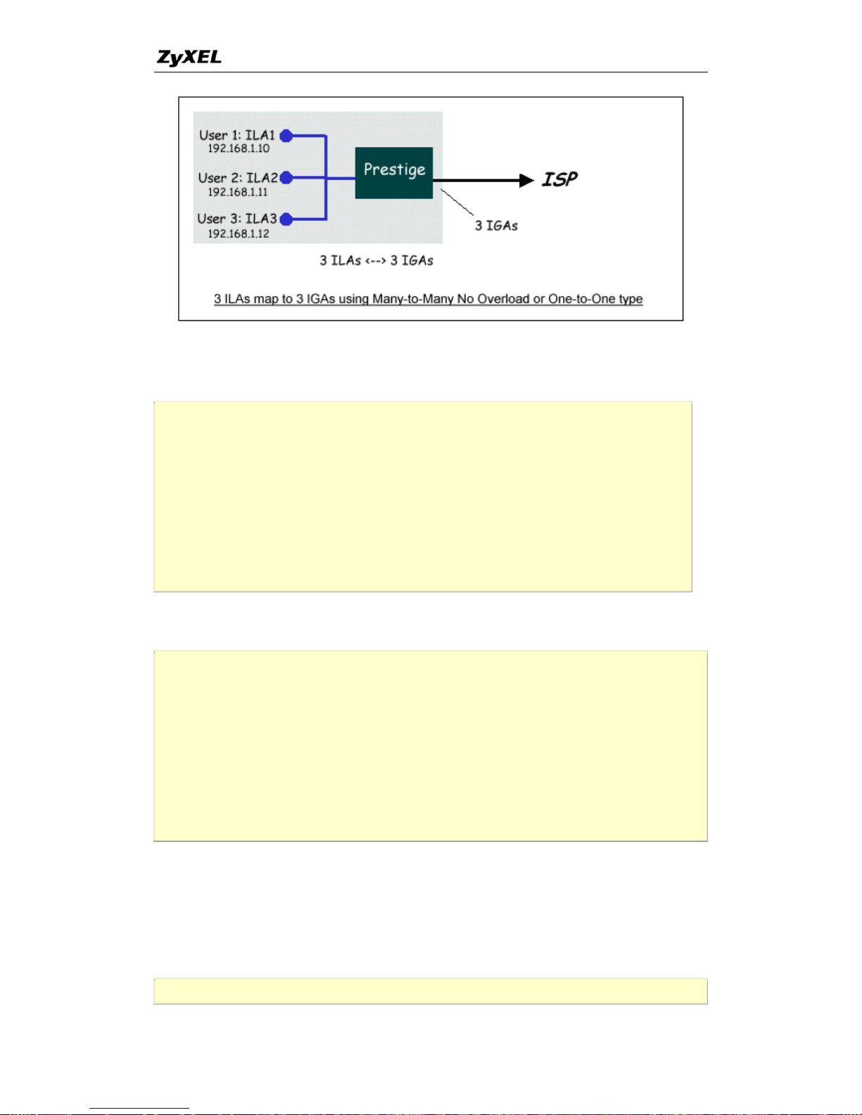
P-660 series Support Notes
One u o Overload mapping type is shown
below.
r le configured for using Many-to-Many N
Menu 15.1.1.1 - - Rule 1
Type: Many-to-Many No Overload
Local IP:
Start= 192.168.1.10
End = 192.168.1.12
Global IP:
Start= [Enter IGA1]
End = [Enter IGA3]
Press ENTER to Confirm or ESC to Cancel:
The three rules configured for using One-to-One mapping type is shown below.
Menu 15.1.1.1 - - Rule 1
Type: One-to-One
Local IP:
Start= 192.168.1.10
End = N/A
Global IP:
Start= [Enter IGA1]
End = N/A
Press ENTER to Confirm or ESC to Cancel:
Menu 15.1.1.2 - - Rule 2
59
All contents copyright © 2005 ZyXEL Communications Corporation.
Page 61
P-660 series Support Notes
Type: One-to-One
Local IP:
Start= 192.168.1.11
End = N/A
l IP: Globa
Start= [Enter IGA2]
End = N/A
Press ENTER to Confirm or ESC to Cancel:
Menu 15.1.1.3 - - Rule 3
Type: One-to-One
Local IP:
Start= 192.168.1.12
End = N/A
Global IP:
Start= [Enter IGA3]
End = N/A
Press ENTER to Confirm or ESC to Cancel:
6
How does ZyXEL filter work?
. About Filter & Filter Examples
configure up to twelve filter sets with six rules in each set,
an apply up to four filter sets to a
f packets. With each filter set having up to six
4 rules active for a single port. The following
low when executing a filter rule.
Filter Structure
The P-660 allows you to
for a total of 72 filter rules in the system. You c
particular port to block multiple types o
rules, you can have a maximum of 2
diagram illustrates the logic f
60
All contents copyright © 2005 ZyXEL Communications Corporation.
Page 62
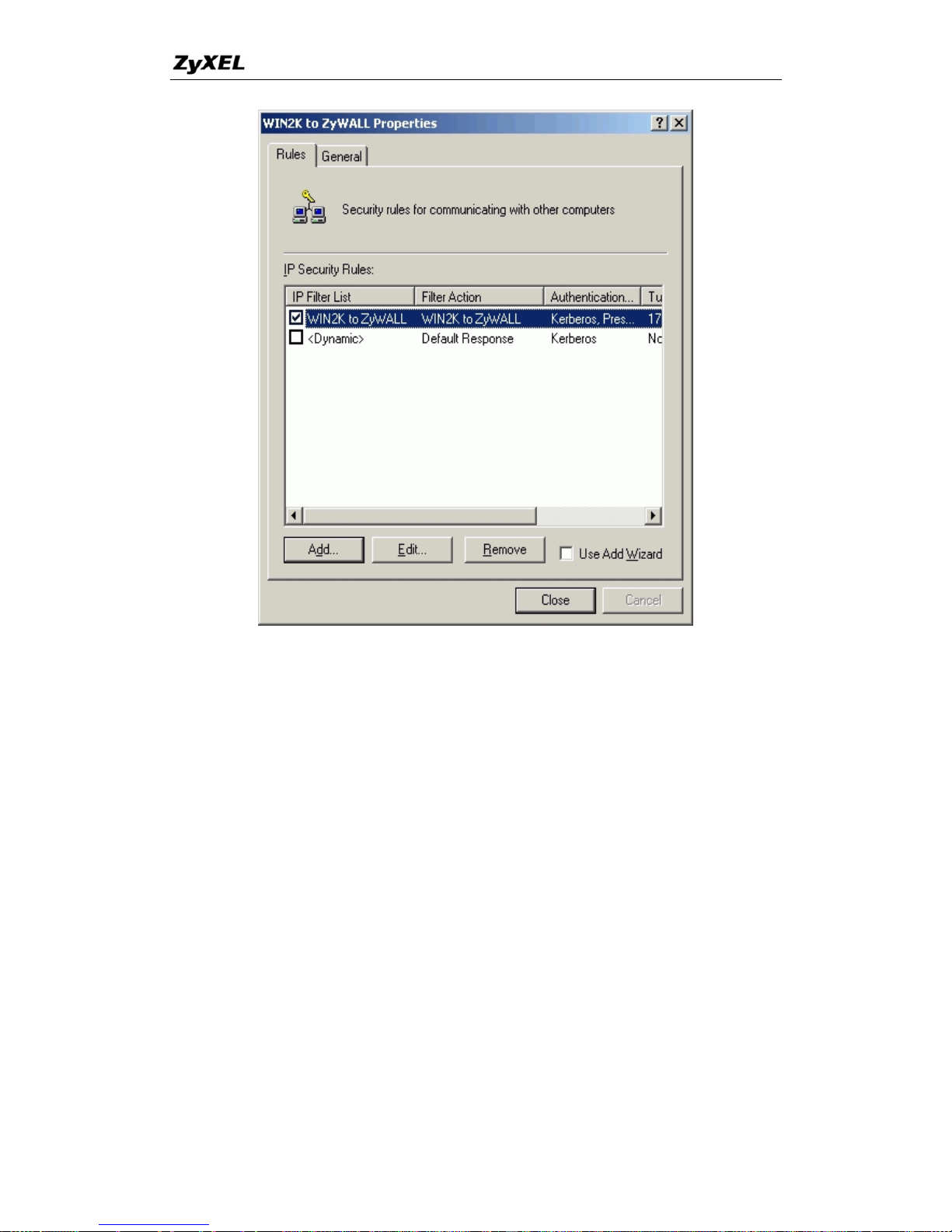
P-660 series Support Notes
Filter Types and SUA
Conceptually, there are two categories of filter rules:
Generic filter rules belong to the device category
LAN and WAN. The IP and IPX filter rules belong to
on the IP and IPX packets.
In order to allow users to specify the local network
filter rules with SUA connections, the TCP/IP filter function has to be executed before
SUA for WAN outgoing pac
But at the same time, the Generic filter rules m
P-660 is receiving and sending the packets; i.e. the ISDN interface. So, the execution
device and protocol. The
; they act on the raw data from/to
the protocol category; they act
IP address and port number in the
kets and after the SUA for WAN incoming IP packets.
ust be applied at the point when the
ged. The logic flow of the filter is shown in Figure 1 and the
e logic flow for the packet from LAN to WAN is:
sets.
output filter sets.
A converts the source IP address from 192.168.1.33 to
rt number from 1023 to 4034.
sequence has to be chan
sequence of th
• LAN device and protocol input filter
• WAN protocol call and
• If SUA is enabled, SU
203.205.115.6 and po
61
All contents copyright © 2005 ZyXEL Communications Corporation.
Page 63
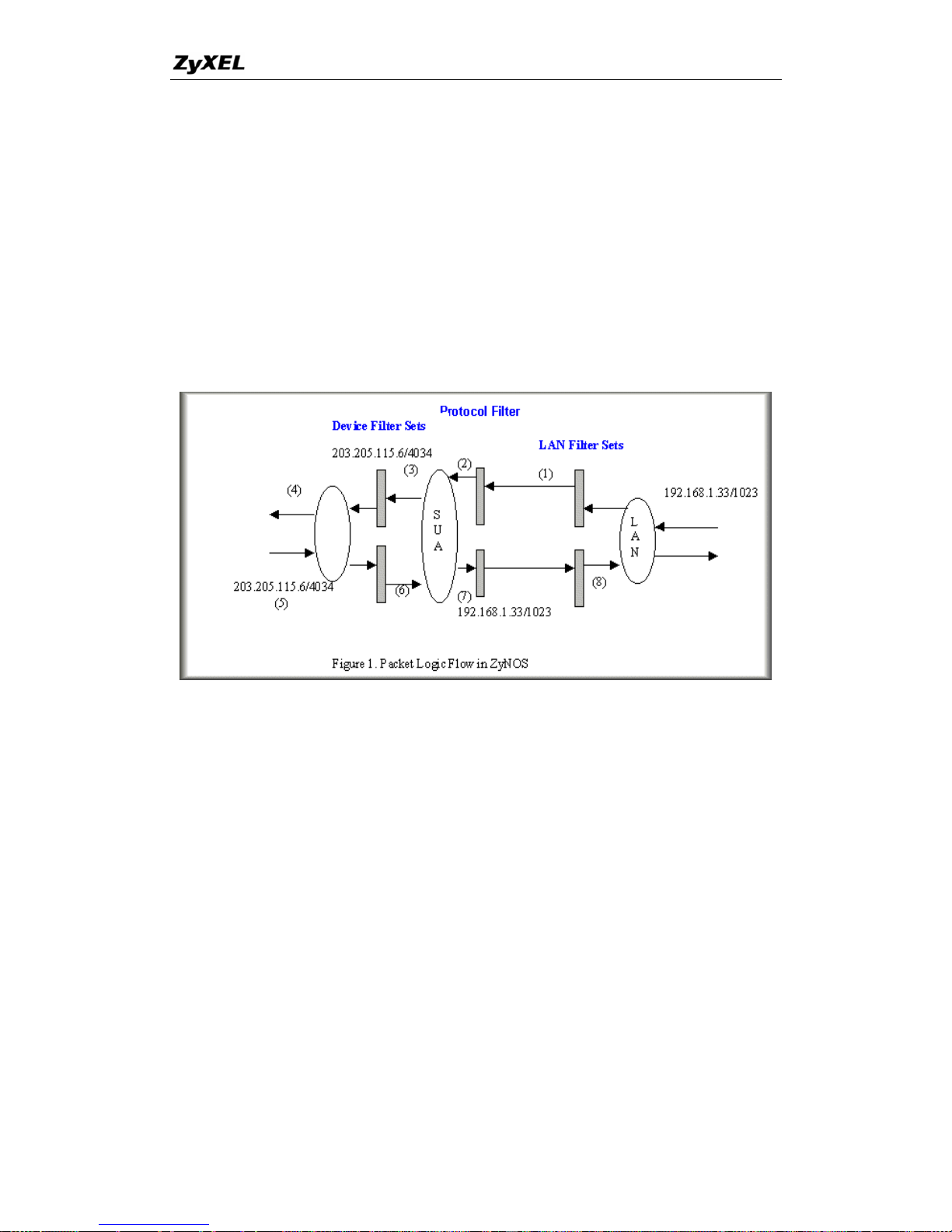
P-660 series Support Notes
d call filter sets.
w for the packet from WAN to LAN is:
• WAN device output an
The sequence of the logic flo
WAN device input filter sets.
If SUA is enabled, SUA converts the destination IP address from 203.205.115.6 to
92.168.1.33 and port number from 4034 to 1023.
WAN protocol input filter sets.
LAN device and protocol output filter sets.
Gen (and IPX) filter rules are in different filter sets. The SMT will
detect and prevent the mixing of different category rules within any filter set in Menu
nd device
filter rules cannot be active together' if you try to activate a TCP/IP (or IPX) filter
Generic filter rules. You will
u try to activate a Generic filter rule in a filter set that has
eric and TCP/IP
21. In the following example, you will receive an error message 'Protocol a
rule in a filter set that has already had one or more active
receive the same error if yo
already had one or more active TCP/IP (or IPX) filter rules.
Menu 21.1.1:
62
All contents copyright © 2005 ZyXEL Communications Corporation.
Page 64

P-660 series Support Notes
Menu 21.1.1 - Generic Filter Rule
Filter #: 1,1
Filter Type= Generic Filter Rule
Active= Yes
Offset= 0
Length= 0
Mask= N/A
Value= N/A
More= No Log= None
Action Matched= Check Next Rule
Action Not Matched= Check Next Rule
Menu 21.1.2:
Menu 21.1.2 - TCP/IP Filter Rule
Filter #: 1,2
Filter Type= TCP/IP Filter Rule
Active= Yes
IP Protocol= 0 IP Source Route= No
Destination: IP Addr= 0.0.0.0
IP Mask= 0.0.0.0
Port #= 0
Port # Comp= None
Source: IP Addr= 0.0.0.0
IP Mask= 0.0.0.0
Port #= 0
Port # Comp= None
TCP Estab= N/A
More= No Log= None
Action Matched= Check Next Rule
Action Not Matched= Check Next Rule
Press ENTER to Confirm or ESC to Cancel:
Saving to ROM. Please wait...
Protocol and device rule cannot be active together
To separate the device and
Menu 13.1, have been added, as well a
11.1, and Menu 13. The new
protocol filter categories; two new menus, Menu 11.5 and
s some changes made to the Menu 3.1, Menu
fields are shown below.
63
All contents copyright © 2005 ZyXEL Communications Corporation.
Page 65

P-660 series Support Notes
Menu 3.1:
Menu 3.1 - General Ethernet Setup
Input Filter Sets:
protocol filters=
device filters=
Output Filter Sets:
protocol filters=
device filters=
Menu 11.1:
Menu 11.1 - Remote Node Profile
Rem Node Name= LAN Route= IP
Active= Yes Bridge= No
Encapsulation= PPP Edit PPP Options= No
Incoming: Rem IP Addr= ?
Rem Login= test Edit IP/IPX/Bridge= No
Rem Password= ********
Outgoing: Session Options:
My Login= testt Edit Filter Sets= Yes
My Password= *****
Authen= CHAP/PAP
Press ENTER to Confirm or ESC to Cancel:
Menu 11.5:
Menu 11.5 - Remote Node Filter
Input Filter Sets:
protocol filters=
device filters=
Output Filter Sets:
protocol filters=
device filters=
SMT will also prevent you from enter
to the device filters field in Menu 3
protocol filters field. Even though SM
entered in ZyNOS, it is unable to res
ing a protocol filter set configured in Menu 21
.1, 11.5, or entering a device filter set to the
T will prevent the inconsistency from being
olve the intermixing problems existing in the
64
All contents copyright © 2005 ZyXEL Communications Corporation.
Page 66

P-660 series Support Notes
red before. Instead, when ZyNOS translates the old
ll verify the filter rules and log the
ystem log (Menu 24.3.1) before putting your device
he P-660 will disable its
routing/bridging functions if there is an inconsistency among its filter rules.
1. A filter for blocking the web service
client
3. A filter for blocking a specific MAC address
BIOS packets
Configuration
Before configuring a filter, you need to know the following information:
uld be as following:
t, TCP (06) protocol with port number 80
b. DNS packet, TCP (06) protocol with port number 53 or
number 53
address will be 0.0.0.0. Otherwise, you
have to enter an IP Address for the workstation you want to block. See the procedure
.1.2, Menu 21.1.3
ol with port number 80
l with port number 53
l with port number 53
3. Apply the filter set in menu 4
filter sets that were configu
configuration into the new format, it wi
inconsistencies. Please check the s
into use.
In order to avoid operational problems later, t
Filter Examples
2. A filter for blocking a specific
4. A filter for blocking the Net
A filter for blocking the web service
1. The outbound packet type (protocol & port number)
2. The source IP address
Generally, the outbound packets for Web service co
a. HTTP packe
c. DNS packet, UDP (17) protocol with port
For all workstation on the LAN, the source IP
for configuring this filter below.
1. Create a filter set in Menu 21, e.g., set 1
2. Create three filter rules in Menu 21.1.1, Menu 21
• Rule 1- block the HTTP packet, TCP (06) protoc
• Rule 2- block the DNS packet, TCP (06) protoco
• Rule 3- block the DNS packet, UDP (17) protoco
65
All contents copyright © 2005 ZyXEL Communications Corporation.
Page 67

P-660 series Support Notes
Create a filter set in Menu 21 1.
Menu 21 - Filter Set Configuration
Filter Filter
Set # Comments Set # Comments
------ ---------------- - ------ -----------------
1 Web Request 7 _______________
2 _______________ 8 _______________
3 _______________ 9 _______________
4 _______________ 10 _______________
5 _______________ 11 _______________
6 _______________ 12 _______________
Enter Filter Set Number to Configure= 1
Edit Comments=
Press ENTER to Confirm or ESC to Cancel:
2. Rule 1 for (a). http packet, TCP(06)/Port number 80
Menu 21.1.1 - TCP/IP Filter Rule
Filter #: 1,1
Filter Type= TCP/IP Filter Rule
Active= Yes
IP Protocol= 6 IP Source Route= No
Destination: IP Addr= 0.0.0.0
IP Mask= 0.0.0.0
Port #= 80
Port # Comp= Equal
Source: IP Addr= 0.0.0.0
IP Mask= 0.0.0.0
Port #=
Port # Comp= None
TCP Estab= No
More= No Log= None
Action Matched= Drop
Action Not Matched= Check Next Rule
Press ENTER to Confirm or ESC to Cancel:
3.Rule 2 for (b).DNS request, TCP(06)/Port number 53
66
All contents copyright © 2005 ZyXEL Communications Corporation.
Page 68

P-660 series Support Notes
Menu 21.1.2 - TCP/IP Filter Rule
Filter#=1,2
Filter Type= TCP/IP Filter Rule
Active= Yes
IP Protocol= 6 IP Source Route= No
Destination: IP Addr= 0.0.0.0
IP Mask= 0.0.0.0
Port #= 53
Port # Comp= Equal
Source: IP Addr= 0.0.0.0
IP Mask= 0.0.0.0
Port #=
Port # Comp= None
TCP Estab= No
More= No Log= None
Action Matched= Drop
Action Not Matched= Check Next Rule
Press ENTER to Confirm or ESC to Cancel:
4. Rule 3 for (c). DNS packet UDP(17)/Port number 53
Menu 21.1.2 - TCP/IP Filter Rule
Filter#=1,3
Filter Type= TCP/IP Filter Rule
Active= Yes
IP Protocol= 17 IP Source Route= No
Destination: IP Addr= 0.0.0.0
IP Mask= 0.0.0.0
Port #= 53
Port # Comp= Equal
Source: IP Addr= 0.0.0.0
IP Mask= 0.0.0.0
Port #=
Port # Comp= None
TCP Estab= No
More= No Log= None
Action Matched= Drop
Action Not Matched= Forward
Press ENTER to Confirm or ESC to Cancel:
67
All contents copyright © 2005 ZyXEL Communications Corporation.
Page 69

P-660 series Support Notes
s are completed, you will see the rule summary in Menu 21.
5. After the three rule
Menu 21.1 - Filter Rules Summary
# A Type Filter Rules M m n
- - ---- -------------------------------------- - - -
1 Y IP Pr=6, SA=0.0.0.0, DA=0.0.0.0, DP=80 N D N
2 Y IP Pr=6, SA=0.0.0.0, DA=0.0.0.0, DP=53 N D N
3 Y IP Pr=17, SA=0.0.0.0, DA=0.0.0.0,DP=53 N D F
6. Apply the filter set to the 'Output Protocol Filter Set'
A filter for
Configuration
1. Create a filter set in M
in the remote node setup
blocking a specific client
enu 21, e.g., set 1
Menu 21 - Filter Set Configuration
Filter Filter
Set # Comments Set # Comments
------ ----------------- ------ -----------------
1 Block a client 7 _______________
2 _______________ 8 _______________
3 _______________ 9 _______________
4 _______________ 10 _______________
5 _______________ 11 _______________
6 _______________ 12 _______________
Enter Filter Set Number to Configure= 0
Edit Comments=
Press ENTER to Confirm or ESC to Cancel:
68
All contents copyright © 2005 ZyXEL Communications Corporation.
Page 70

P-660 series Support Notes
2. One rule for blocking all packets from this client
Menu 21.1.1 - TCP/IP Filter Rule
Filter #: 1,1
Filter Type= TCP/IP Filter Rule
Active= Yes
IP Protocol= 0 IP Source Route= No
Destination: IP Addr= 0.0.0.0
IP Mask= 0.0.0.0
Port #=
Port # Comp= None
Source: IP Addr= 192.168.1.5
IP Mask= 255.255.255.255
Port #=
Port # Comp= None
TCP Estab= N/A
More= No Log= None
Action Matched= Drop
Action Not Matched= Forward
irm or ESC to Cancel: Press ENTER to Conf
Key Se
Source IP addr................Enter the client IP in this field
IP Mask..........................Here the IP mask is used to mask the bits of the IP address
given in tation it is 255.255.255.255.
Action Matched................Set to 'Drop' to drop all the packets from this client
Action Not Matched.........Set to '
3. Appl umber '1' to the 'Output Protocol Filter Set' field in the
remote
A filter for blocking a specific MAC address
This co
MAC a
Before you Begin
ttings:
the 'Source IP Addr=' field, for one works
Forward' to allow the packets from other clients
y the filter set n
node setup.
nfiguration example shows you how to use a Generic Filter to block a specific
ddress of the LAN.
69
All contents copyright © 2005 ZyXEL Communications Corporation.
Page 71

P-660 series Support Notes
Bef e ilter, you need to know the MAC address of the client first.
The MA
through the P-660 you can identify the uninteresting MAC address from the P-660's
LAN packet trace. Please have a look at the following example to know the trace of
the
or you configure the f
C address can be provided by the NICs. If there is the LAN packet passing
LAN packets.
ras> sys trcp channel enet0 bothway
ras> sys trcp sw on
Now a c t on the LAN is trying to ping Prestige……… lien
ras> sys trcp sw off
ras> sys trcp disp
TIME: 37c060 enet0-RECV len:74 call=0
0000: 8 4c ea 63] 08 00 45 00 [00 a0 c5 01 23 45] [00 80 c
0010: 00 3c eb 0c 00 00 20 01 e3 ea ca 84 9b 5d ca 84
0020: 0 61 62 63 64 65 66 9b 63 08 00 45 5c 03 00 05 0
0030: f 70 71 72 73 74 75 76 67 68 69 6a 6b 6c 6d 6e 6
0040: 8 69 77 61 62 63 64 65 66 67 6
TIME: 37c060 enet0-XMIT len:74 call=0
0000: 45 00 [00 80 c8 4c ea 63] [00 a0 c5 01 23 45] 08 00
0010: 3 ca 84 00 3c 00 07 00 00 fe 01 f0 ef ca 84 9b 6
0020: 9b 5d 00 00 4d 5c 03 00 05 00 61 62 63 64 65 66
0030: 68 69 6a 6b 6c 6d 6e 6f 70 71 72 73 74 75 76 67
0040: 77 61 62 63 64 65 66 67 68 69
The detailed format of the Ethernet Version II:
+ Ethernet Version II
- Address: 00-80-C8-4C-EA-63 (Source MAC) ----> 00-A0-C5-23-45
(Destination MAC)
- Ethernet II Protocol Type: IP
+ Internet Protocol
- Version (MSB 4 bits): 4
- Header length (LSB 4 bits): 5
- Serv Normal, Thrput=Normal, Reli=Normal ice type: Precd=Routine, Delay=
- Tota gth: 60 (Octets) l len
- Fragment ID: 60172
70
All contents copyright © 2005 ZyXEL Communications Corporation.
Page 72
P-660 series Support Notes
- Flags: May be fragmented, Last fragment, Offset=0 (0x00)
- Time to live: 32 seconds/hops
- IP protocol type: ICMP (0x01)
- Checksum: 0xE3EA
- IP address 202.132.155.93 (Source IP address) ---->
202.132.155.99(Destination IP address)
- No option
+ Internet Control Message Protocol
- Type: 8 - Echo Request
- Code: 0
- Checksum: 0x455C
- Identifier: 768
- Sequence Number: 1280
- Optional Data: (32 bytes)
Configurations
From the a uter.
And from the second trace, we know the Paccordingly ock
the MAC a
1. First, fro
address sta
bove first trace, we know a client is trying to ping request the P-660 ro
660 router will send a reply to the client
. The following sample filter will utilize the 'Generic Filter Rule' to bl
ddress [00 80 c8 4c ea 63].
m the incoming LAN packet we know the uninteresting source MAC
rts at the 7th Octet
TIME: 37c060 enet0-RECV len:74 call=0
0000: [00 a0 c5 01 23 45] [00 80 c8 4c ea 63] 08 00 45 00
0010: 00 3c eb 0c 00 00 20 01 e3 ea ca 84 9b 5d ca 84
0020: 9b 63 08 00 45 5c 03 00 05 00 61 62 63 64 65 66
0030: 67 68 69 6a 6b 6c 6d 6e 6f 70 71 72 73 74 75 76
0040: 77 61 62 63 64 65 66 67 68 69
2. We are now ready to configure the 'Generic Filter Rule' as below.
Men r Rule u 21.1.1 - Generic Filte
Filter #: 1,1
Filter Type= Generic Filter Rule
Active= Yes
Offset= 6
Length= 6
Mask= ffffffffffff
Value= 0080c84cea63
71
All contents copyright © 2005 ZyXEL Communications Corporation.
Page 73
P-660 series Support Notes
More= No Log= None
Action Matched= Drop
Action Not Matched= Forward
Key Settings:
• Generic Filter Ruls
Set the 'Filter Type' to 'Generic Filter Rule'
• Active
Set to '6' since the source MAC address starts at 7th octets we need to skip the
ress.
octets.
cally qualify (logical AND) the data
ctets the Mask for it should be 12 hexadecimal
t to 'ffffffffffff' to mask the incoming
4c ea 63].
that the P-660 should use to
t. If the result from the masked packet matches
atched.
acket matches the 'Value'. In this
case, we will drop it.
• Action Not Matched=
. In
this case, we will forward it. If you want to configure more rules please select
'Check Next Rule' to start configuring the next new rule. However, please note
not others. Because
the Generic and TCPIP (IPX) filter rules must be in different filter sets.
Turn 'Active' to 'Yes'
• Offset (in bytes)
first octets of the destination MAC add
Length (in bytes)
Set to '6' since MAC address has 6
Mask (in hexadecimal)
Specify the value that the P-660 will logi
in the packet.
Since the Length is set to 6 o
numbers. In this case, we intent to se
source MAC address, [00 80 c8
• Value (in hexadecimal)
Specify the MAC address [00 80 c8 4c ea 63]
compare with the masked packe
the 'Value', then the packet is considered m
• Action Matched=
Enter the action you want if the masked p
Enter the action you want if the masked packet does not match the 'Value'
that the 'Filter Type' must be also 'Generic Filter Rule' but
72
All contents copyright © 2005 ZyXEL Communications Corporation.
Page 74

P-660 series Support Notes
Menu 21.1.2 - Generic Filter Rule
Filter #: 1,2
Filter Type= Generic Filter Rule
Active= Yes
Offset= 6
Length= 6
Mask= ffffffffffff
Value= 0080c810234a
More= No Log= None
Action Matched= Drop
Action Not Matched= Forward
You can now apply it to the 'General Ethernet Setuthp' in Menu 3.1. Please note that
e 'Generic Filter' can only be applied to the 'Device Filter' but not the 'Protocol
Filter' that is used for configuring the TCPIP and IPX filters.
Menu 3.1 - General Ethernet Setup
Input Filter Sets:
protocol filters=
device filters= 1
Output Filter Sets:
protocol filters=
device filters=
A filter for blocking the NetBIOS packets
Introduction
The NETBIOS protocol is use
the security concern, the NetBIOS conn
router as factory defaults. Users can rem
menu 4.1 for activating the NetBIOS ser
described as follows.
d to share a Microsoft comupter of a workgroup. For
ection to a outside host is blocked by P-660
ove the filter sets applied to menu 3.1 and
vices. The details of the filter settings are
Configuration
73
All contents copyright © 2005 ZyXEL Communications Corporation.
Page 75

P-660 series Support Notes
packets need to be blocked are as follows. Please configure two filter sets with 4
and 2 rules respectively based on the following packets in SMT menu 21.
Filter Set 1:
Rule 1-Destination port number 137 with protocol number 6 (TCP)
)
Rule 3-Destination port number 138 with protocol number 6 (TCP)
Rule 4-Destination port number 138 with protocol number 17 (UDP)
r 139 with protocol number 6 (TCP)
ith protocol number 17 (UDP)
37, Destination port number 53 with protocol
t number 137, Destination port number 53 with protocol
ase enter a name for each filter set in the
The
Rule 2-Destination port number 137 with protocol number 17 (UDP
Rule 5-Destination port numbe
Rule 6-Destination port number 139 w
Filter Set 2:
Rule 1-Source port number 1
number 6 (TCP)
Rule 2-Source por
number 17 (UDP)
Before starting to set the filter rules, ple
'Comments' field first.
Menu 21 - Filter Set Configuration
Filter Filter
Set # Comments Set # Comments
------ ---------------- - ------ -----------------
1 NetBIOS_WAN 7 _______________
2 NetBIOS_LAN 8 _______________
3 _______________ 9 _______________
4 _______________ 10 _______________
5 _______________ 11 _______________
6 _______________ 12 _______________
Enter Filter Set Number to Configure= 1
Edit Comments=
Press ENTER to Confirm or ESC to Cancel:
Configure the first filter set 'NetBIOS_WAN' by selecting the Filter Set number 1.
74
All contents copyright © 2005 ZyXEL Communications Corporation.
Page 76

P-660 series Support Notes
number 137 with protocol number 6 (TCP) • Rule 1-Destination port
Menu 21.1.1 - TCP/IP Filter Rule
Filter #: 1,1
Filter Type= TCP/IP Filter Rule
Active= Yes
IP Protocol= 6 IP Source Route= No
Destination: IP Addr= 0.0.0.0
IP Mask= 0.0.0.0
Port #= 137
Port # Comp= Equal
Source: IP Addr= 0.0.0.0
IP Mask= 0.0.0.0
Port #= 0
Port # Comp= None
TCP Estab= No
More= No Log= None
Action Matched= Drop
Action Not Matched= Check Next Rule
• Rule 2-Destination port number 137 with protocol number 17 (UDP)
Menu 21.1.2 - TCP/IP Filter Rule
Filter #: 1,2
Filter Type= TCP/IP Filter Rule
Active= Yes
IP Protocol= 17 IP Source Route= No
Destination: IP Addr= 0.0.0.0
IP Mask= 0.0.0.0
Port #= 137
Port # Comp= Equal
Source: IP Addr= 0.0.0.0
IP Mask= 0.0.0.0
Port #= 0
Port # Comp= None
TCP Estab= N/A
More= No Log= None
Action Matched= Drop
75
All contents copyright © 2005 ZyXEL Communications Corporation.
Page 77

P-660 series Support Notes
Action Not Matched= Check Next Rule
Press ENTER to Confirm or ESC to Cancel:
• Rule 3-Destination port number 138 with protocol number 6 (TCP)
Menu 21.1.3 - TCP/IP Filter Rule
Filter #: 1,3
Filter Type= TCP/IP Filter Rule
Active= Yes
IP Protocol= 6 IP Source Route= No
Destination: IP Addr= 0.0.0.0
IP Mask= 0.0.0.0
Port #= 138
Port # Comp= Equal
Source: IP Addr= 0.0.0.0
IP Mask= 0.0.0.0
Port #= 0
Port # Comp= None
TCP Estab= No
More= No Log= None
Action Matched= Drop
Action Not Matched= Check Next Rule
Press ENTER to Confirm or ESC to Cancel:
• Rule 4-Destination port number 138 with protocol number 17 (UDP)
Menu 21.1.4 - TCP/IP Filter Rule
Filter #: 1,4
Filter Type= TCP/IP Filter Rule
76
All contents copyright © 2005 ZyXEL Communications Corporation.
Page 78

P-660 series Support Notes
Active= Yes
IP Protocol= 17 IP Source Route= No
Destination: IP Addr= 0.0.0.0
IP Mask= 0.0.0.0
Port #= 138
Port # Comp= Equal
Source: IP Addr= 0.0.0.0
IP Mask= 0.0.0.0
Port #= 0
Port # Comp= None
TCP Estab= N/A
More= No Log= None
Action Matched= Drop
Action Not Matched= Check Next Rule
Press ENTER to Confirm or ESC to Cancel:
• Rule 5-Destination port number 139 with protocol number 6 (TCP)
nu 21.1.5 - TCP/IP Filter Rule Me
Filter #: 1,5
Filter Type= TCP/IP Filter Rule
Active= Yes
IP Protocol= 6 IP Source Route= No
Destination: IP Addr= 0.0.0.0
IP Mask= 0.0.0.0
Port #= 139
Port # Comp= Equal
Source: IP Addr= 0.0.0.0
IP Mask= 0.0.0.0
Port #= 0
Port # Comp= None
TCP Estab= No
More= No Log= None
Action Matched= Drop
Action Not Matched= Check Next Rule
Press ENTER to Confirm or ESC to Cancel:
77
All contents copyright © 2005 ZyXEL Communications Corporation.
Page 79

P-660 series Support Notes
mber 139 with protocol number 17 (UDP) • Rule 6-Destination port nu
Menu 21.1.6 - TCP/IP Filter Rule
Filter #: 1,6
Filter Type= TCP/IP Filter Rule
Active= Yes
IP Protocol= 17 IP Source Route= No
Destination: IP Addr= 0.0.0.0
IP Mask= 0.0.0.0
Port #= 139
Port # Comp= Equal
Source: IP Addr= 0.0.0.0
IP Mask= 0.0.0.0
Port #= 0
Port # Comp= None
TCP Estab= N/A
More= No Log= None
Action Matched= Drop
Action Not Matched= Forward
Press ENTER to Confirm or ESC to Cancel:
After the first filter set is finished, you will get the complete rules summary as below.
Menu 21.2 - Filter Rules Summary
# A Type Filter Rules M m n
- - ---- --------------------------------------------- - - -
1 Y IP Pr=6, SA=0.0.0.0, DA=0.0.0.0, DP=137 N D N
2 Y IP Pr=17, SA=0.0.0.0, DA=0.0.0.0, DP=137 N D N
3 Y IP Pr=6, SA=0.0.0.0, DA=0.0.0.0, DP=138 N D N
4 Y IP Pr=17, SA=0.0.0.0, DA=0.0.0.0, DP=138 N D N
5 Y IP Pr=6, SA=0.0.0.0, DA=0.0.0.0, DP=139 N D N
6 Y IP Pr=17, SA=0.0.0.0, DA=0.0.0.0, DP=139 N D F
Apply the first filter set 'NetBIOS_WAN' to the 'Output Protocol Filter' in the
rem
Con
numbe
ote node setup.
figure the second filter set 'NetBIOS_LAN' by selecting the Filter Set
r 2.
78
All contents copyright © 2005 ZyXEL Communications Corporation.
Page 80

P-660 series Support Notes
ule 1-Source port number 137, Destination port number 53 with protocol number 6 R
(TCP)
Menu 21.2.1 - TCP/IP Filter Rule
Filter #: 2,1
Filter Type= TCP/IP Filter Rule
Active= Yes
IP Protocol= 6 IP Source Route= No
Destination: IP Addr= 0.0.0.0
IP Mask= 0.0.0.0
Port #= 53
Port # Comp= Equal
Source: IP Addr= 0.0.0.0
IP Mask= 0.0.0.0
Port #= 137
Port # Comp= Equal
TCP Estab= No
More= No Log= None
Action Matched= Drop
Action Not Matched= Check Next Rule
Press ENTER to Confirm or ESC to Cancel:
1. Rule 2-Source port
number 17 (UDP)
number 137, Destination port number 53 with protocol
Menu 21.2.2 - TCP/IP Filter Rule
Filter #: 2,2
Filter Type= TCP/IP Filter Rule
Active= Yes
IP Protocol= 17 IP Source Route= No
Destinatio .0.0 n: IP Addr= 0.0
IP Mask= 0.0.0.0
Port #= 53
P l ort # Comp= Equa
Source: IP Addr= 0.0.0.0
IP Mask= 0.0.0.0
Port #= 137
Port # Comp= Equal
TCP Estab= N/A
More= No Log= None
79
All contents copyright © 2005 ZyXEL Communications Corporation.
Page 81

P-660 series Support Notes
Action Matched= Drop
Action Not Matched= Forward
Press ENTER to Confirm or ESC t ncel: o Ca
2. After the first filter set is finished, you will get the complete rules summary as
below.
Menu 21.2 - Filter Rules Summary
# A Type Filter Rules M m n
- - ---- ---------------------------------------------- - - -
1 Y IP Pr=6, SA=0.0.0 .0, SP=137, DA=0.0.0.0, DP=53 N D N
2 Y IP Pr=17, SA=0.0.0.0, SP=137, DA=0.0.0.0, DP=53 N D F
Apply the filter set ' in the 'Input protocol filters=' in the 3. NetBIOS_LAN'
Menu 3 for blocking the packets from LAN
Menu 3.1 - General Ethernet Setup
Input Filter Sets:
protocol filters= 2
device filters=
Output Filter Sets:
protocol filters=
device filters=
7. Using the Dynamic DNS (DDNS)
eved.
with dynamic IPs.
• What is DDNS?
The DDNS service, an IP Registry provides a public central database where
information such as email addresses, hostnames, IPs etc. can be stored and retri
This solves the problems if your DNS server uses an IP associated
80
All contents copyright © 2005 ZyXEL Communications Corporation.
Page 82

P-660 series Support Notes
., www.zyxel.com.tw) for your
server (e.g., Web server) from a DDNS server. The outside users can always access
.
When the ISP assigns the P-660 a new IP, the P-660 must inform the DDNS server
e of this IP so that the server can update its IP-to-DNS entry. Once the
IP-to-DNS table in the DDNS server is updated, the DNS name for your web server
(i.e., w
The DDNS server stores password-protected email addresses with IPs and hostnames
ts queries based on email addresses. So, there must be an email entry in the
P-660 menu 1.
The DDNS servers the P-660 supports currently is WWW.DYNDNS.ORG where you
apply the DNS from and update the WAN IP to.
• Set
1. Before configuring the DDNS settings in the P-660, you must register an
ccount from the DDNS server such as WWW.DYNDNS.ORG first. After the
registration, you have a hostname for your internal server and a password
2. 'Configure Dynamic DNS' option to 'Yes' and press ENTER for
configuring the settings of the DDNS in menu 1.1.
Without DDNS, we always tell the users to use the WAN IP of the P-660 to access the
internal server. It is inconvenient for the users if this IP is dynamic. With DDNS
supported by the P-660, you apply a DNS name (e.g
the web server using the www.zyxel.com.tw regardless of the WAN IP of the P-660
the chang
ww.zyxel.com.tw) is still usable.
and accep
up the DDNS
a
using to update the IP to the DDNS server.
Toggle
Menu 1 - Genera l Setup
System Name= P-660
Location=
t Person's Name= Contac
Domain Name=
amic DNS= Yes Edit Dy n
Route IP= Yes
Bridge= No
81
All contents copyright © 2005 ZyXEL Communications Corporation.
Page 83
P-660 series Support Notes
Menu 1.1 - Configure Dynamic DNS
Service Provider= WWW.DynDNS.ORG
Active= Yes
Host= [the local server's host name]
EMAIL= [your email address]
User=
Password= ********
Enable Wildcard= No
Key Settings for using DDNS function:
Option Description
Service Provider
Enter the DDNS server in this field. Currently, we support
WWW.DYNDNS.ORG.
Active
Toggle to 'Yes'.
Host
Enter the hostname you subscribe from the above DDNS server. For
example, zyxel.com.tw.
EMAIL
Enter the email address you give to the DDNS server.
User
Enter the user name that
Passwo
server gives to you.
rd
Enter the password that the DDNS
Ena le
at the
ailable
b
Enter the hostname for the wildcard function th
Wildcard
WWW.DYNDNS.ORG supports. Note that Wildcard option is av
only when the provider is
http://www.dyndns.org/.
8. etwork Management Using SNN MP
ocol suite, it uses the UDP to exchange messages between a management
Client and an Agent, residing in a network node.
• SNMP Overview
The Simple Network Management Protocol (SNMP) is an applications-layer protocol
used to exchange the management information between network devices (e.g.,
routers). By using SNMP, network administrators can more easily manage network
performance, find and solve network problems. The SNMP is a member of the
TCP/IP prot
82
All contents copyright © 2005 ZyXEL Communications Corporation.
Page 84

P-660 series Support Notes
ost of the changes introduced in Version 2 increase SNMP's security
capabilities. SNMP encompasses three main areas:
1. A small set of management operations.
2.
3. Data representation.
The operations allowed are: Get, GetNext, Set, and Trap. These functions operates
on vari e statistic
counters, node port status, and so on. All of the SNMP management functions are
carr
these ca e, a
counter set
after th
SNMP variables are defined using the OSI Abstract Syntax Notation One (ASN.1).
ASN.1
powerf
text str its length and
valu ecially for network
manage anageable
variab
The net of variab Management Information
Bas , including the Standard MIB,
specified as part of SNMP, and Enterprise Specific MIB, which are defined by
The current Internet-standard MIB, MIB-II, is defined in RFC 1213 and contains 171
ouped by protocol (including TCP, IP, UDP, SNMP, and
other categories, including 'system' and 'interface.'
NMS and managed devices can be any of four different types of commands:
Reads
d to monitor the managed devices, NMSs read variables that are
maintained by the devices.
Writes
Write is used to control the managed devices, NMSs write variables that are
stored in the managed devices.
There are two versions of SNMP: Version 1 and Version 2. ZyXEL supports
SNMPv1. M
Definitions of management variables.
ables that exist in network nodes. Examples of variables includ
ied out through these simple operations. No action operations are available, but
n be simulated by the setting of flag variables. For example, to reset a nod
variable named 'time to reset' could be set to a value, causing the node to re
e time had elapsed.
specifies how a variable is encoded in a transmitted data frame; it is very
ul because the encoded data is self-defining. For example, the encoding of a
ing includes an indication that the data unit is a string, along with
e. ASN.1 is a flexible way of defining protocols, esp
ment protocols where nodes may support different sets of m
les.
les that each node supports is called the
e (MIB). The MIB is made up of several parts
different manufacturer for hardware specific management.
objects. These objects are gr
The Internet Management Model is as shown in figure 1. Interactions between the
Read is use
83
All contents copyright © 2005 ZyXEL Communications Corporation.
Page 85
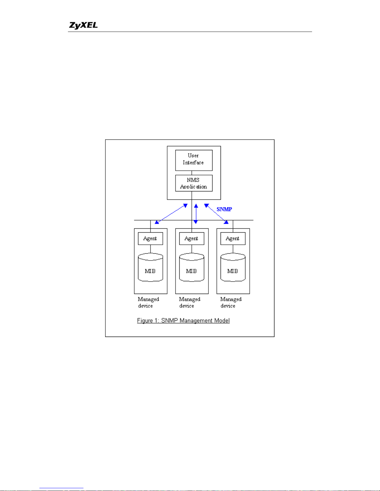
P-660 series Support Notes
Travers
NMSs use these operations to determine which variables a managed device
supports and to sequentially gather information from variable tables (such as
IP routing table) in managed devices.
Traps
The managed devices to asynchronously report certain events to NMSs use
trap.
al operations
• SNMPv1 Operations
SNM
as below.
P itself is efined
Allows variable from the agent.
GetNex
s or list within
an agen
a simple request/response protocol. 4 SNMPv1 operations are d
• Get
the NMS to retrieve an object
•
Allow
t
the NMS to retrieve the next object variable from a table
t. In SNMPv1, when a NMS wants to retrieve all elements of a table
84
All contents copyright © 2005 ZyXEL Communications Corporation.
Page 86
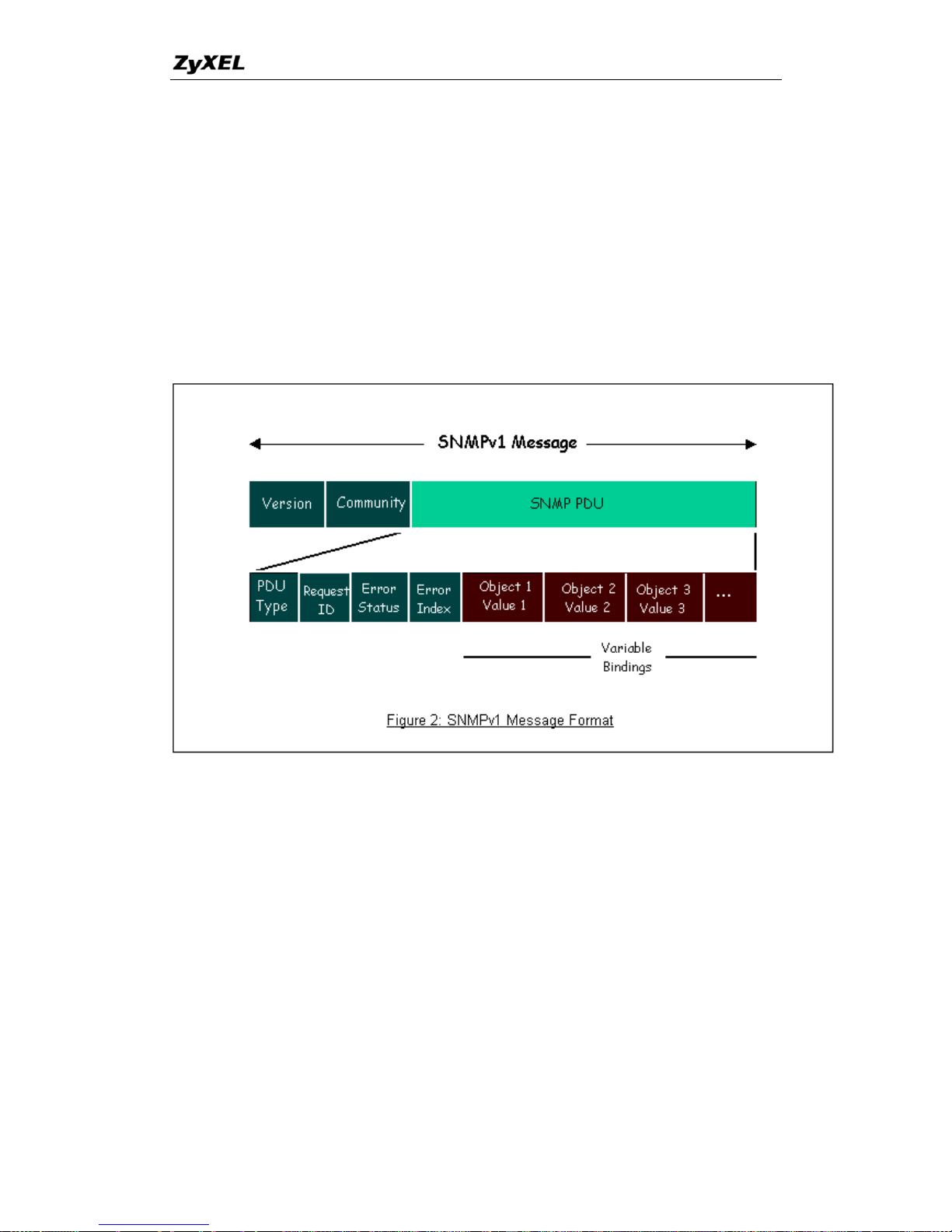
P-660 series Support Notes
n etNext
operations.
• Set
Allows the NMS to set values for object variables within an agent.
Used by the agent to inform the NMS of some events.
The N s contains two part. The first part contains a version and a
com u s the actual SNMP protocol data unit (PDU)
specifying the operation to be performed (Get, Set, and so on) and the object values
involved in the operation. The following figure shows the SNMPv1 message format.
from a agent, it initiates a Get operation, followed by a of G
• Trap
S MPv1 message
m nity name. The second part contain
The SNMP PDU contains the following fields:
• PDU
• Request ID Associates requests with responses.
• Error status Indicates an error and an error type.
type Specifies the type of PDU.
• Error index Associates the error with a particular object variable.
e-bindings Associates particular object with their value.
Further, users can also add ZyXEL's private MIB in the NMS to monitor and control
additional system variables. The ZyXEL's private MIB tree is shown in figure 3. For
• Variabl
• ZyXEL SNMP Implementation
ZyXEL currently includes SNMP support in some P-660 routers. It is implemented
based on the SNMPv1, so it will be able to communicate with SNMPv1 NMSs.
85
All contents copyright © 2005 ZyXEL Communications Corporation.
Page 87

P-660 series Support Notes
an
munity and allows trap messages to be sent to only one NMS
manager.
Some traps are sent to the SNMP manager when anyone of the following events
fined in RFC-1215) :
If the machine coldstarts, the trap will be sent after booting.
215) :
kDow
If any li ort
mber the interface group.
3. linkUp (defined in RFC-1215) :
If any link of IDSL or WAN is up, the trap will be sent with the port number .
port number is its interface index under the interface group.
get or set requirement with wrong community, this
.
the reason
essage "System reboot by user !" will be sent.
System has to reboot for some fatal errors. And traps with the message of the fatal
SNMPv1 operation, ZyXEL permits one community string so that the router c
belong to only one com
happens:
1. coldStart (de
1. warmStart (defined in RFC-1
If the m
2. lin
achine warmstarts, the trap will be sent after booting.
n (defined in RFC-1215) :
nk of IDSL or WAN is down, the trap will be sent with the p
nu . The port number is its interface index under
The
4. authenticationFailure (defined in RFC-1215) :
When receiving any SNMP
trap is sent to the manager
5. whyReboot (defined in ZYXEL-MIB) :
When the system is going to restart (warmstart), the trap will be sent with
of restart before rebooting.
(i) For intentional reboot :
In some cases (download new files, CI command "sys reboot", ...), reboot is done
intentionally. And traps with the m
(ii) For fatal error :
code will be sent.
86
All contents copyright © 2005 ZyXEL Communications Corporation.
Page 88
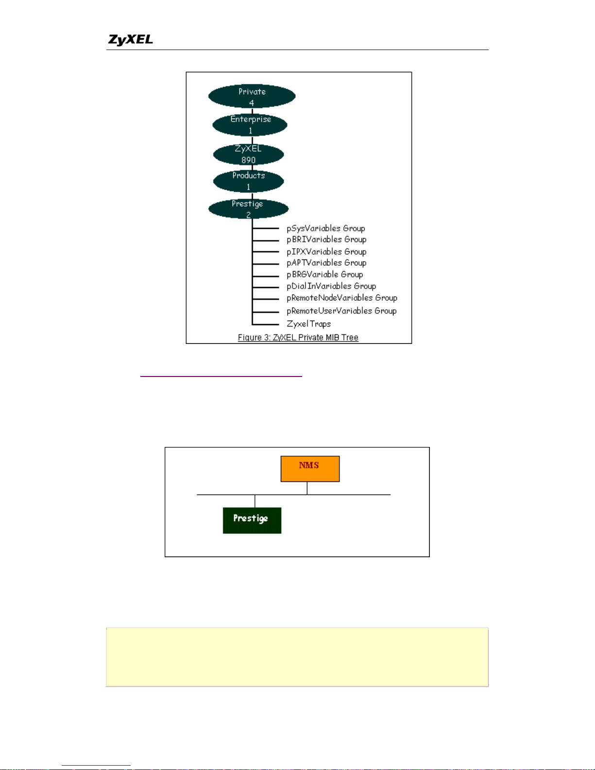
P-660 series Support Notes
• Downloading ZyXEL's private MIB
• Configure the P-660 for SNMP
The SNMP related settings in
The following steps describe a simple
settings.
P-660 are configured in menu 22, SNMP Configuration.
setup procedure for configuring all SNMP
Menu 22 - SNMP Configuration
SNMP:
87
All contents copyright © 2005 ZyXEL Communications Corporation.
Page 89
P-660 series Support Notes
Get Community= public
Set Community= public
Trusted Host= 192.168.1.33
Trap:
Community= public
Destination= 192.168.1.33
Press ENTER to Confirm or ESC to Cancel:
Key Settings:
Option Descriptions
Get
Community
Enter the correct Get Community. This Get Community must match the 'Get-'
and 'GetNext' community requested from the NMS. The default is 'public'.
Set
Community
Enter the correct Set Community. This Set Community must ma
'Set-community requested from the NMS. The default is 'public'
tch the
.
Trusted Host
Enter the IP address of the NMS. The P-660 will only respond to
messages coming from this IP address. If 0.0.0.0 is entered, the
respond to all NMS managers.
SNMP
P-660 will
Trap
Community
Enter the community name in each sent trap to the NMS. This Tra
must match what the NMS is expecting. The default is 'public'.
p Community
Trap
Destination
Enter the IP address of the NMS that you wish to send the traps
entered, the P-660 will not send trap any NMS manager.
to. If 0.0.0.0 is
UNIX Setup
9. Using syslog
• P-660 Setup
•
• ZyXEL Syslog Message Format
P-660 Setup
Menu 24.3.2 - System Maintenance - UNIX S nd Accounting yslog a
UNIX Syslog:
Active= Yes
Syslog IP Address= 192.168.1.33
88
All contents copyright © 2005 ZyXEL Communications Corporation.
Page 90
P-660 series Support Notes
Log Facility= Local 1
Types:
CDR= No
Packet triggered= No
Filter log= No
PPP log= No
Configuration:
1. Active, use the space bar to turn on the syslog option.
2. Syslog IP Address, enter the IP address of the UNIX serv
the syslog.
3. Log Facility, use the space bar to toggle between the 7 di
4. Ty
er that you wish to send
fferent local options.
pes, use the space bar to toggle the logs we are going to record.
-r, t acility to receive message from the network using an
Internet domain socket with the syslog services. The default setting is not enabled.
/etc/syslog.conf by adding the following line at the end of the
/etc/syslog.conf file.
zyxel.log is the full path of the log file.
logs all data phone line activity if set to Yes.
UNIX Setup
1. Make sure that your syslog starts with -r argument.
his option will enable the f
2. Edit the file
local1.* /var/log/zyxel.log
Where /var/log/
3. Restart syslogd.
ZyXEL Syslog Message Format
CDR
Call Detail Record (CDR)
Packet
triggered
The first 48 bytes o
the UNIX syslog server
r octets and protocol type of the triggering packet is sent to
when this field is set to Yes.
Filter log
No filters ar
filter Log
e logged when this field is set to No. Filters with the individual
field set to Yes are logged when this field is set to Yes.
PPP log
PPP events are logged when this field is set to Yes.
89
All contents copyright © 2005 ZyXEL Communications Corporation.
Page 91

P-660 series Support Notes
es)
SYSLOG_CDR, SYSLOG_INFO, String );
String = board xx line xx channel xx, call xx, str
the ha
e WAN ID in a board
AN
call
Outg
Incomi
C01 Incoming Call xxxx (means connected speed) xxxxx (means Remote Call ID)
(means connected speed) xxxxx (means Remote Call
ID)
L02 Call Terminated
1. CDR log(call messag
Format:
sdcmdSyslogSend(
board =
line = th
channel = channel ID within the W
rdware board ID
call = the
call
reference number which starts from 1 and increments by 1 for each new
str = C01
C01
oing Call dev xx ch xx (dev:device No. ch:channel No.)
ng Call xxxxBps xxxxx (L2TP,xxxxx means Remote Call ID)
L02 Tunnel Connected(L2TP)
C02 OutCall Connected xxxx
C02 CLID call refused
C02 Call Terminated
Example:
Feb 14 16:57:17 192.168.1.1 ZyXEL Communications Corp.: board 0 line 0 channel 0, call 18,
C01 Incoming Call OK
Feb 14 17:07:18 192.168.1.1 ZyXEL Communications Corp.: board 0 line 0 channel 0, call 18,
C02 Call Terminated
, SYSLOG_NOTICE, String );
x
Protocol: (1:IP 2:IPX 3:IPXHC 4:BPDU 5:ATALK 6:IPNG)
ata: We will send forty-eight Hex characters to the server
xample:
2. Packet triggered log
Format:
sdcmdSyslogSend( SYSLOG_PKTTRI
String = Packet trigger: Protocol=xx Data=xxxxxxxxx
D
E
Jul 19 11:28:39 192.168.102.2 ZyXEL Communications Corp.: Packet Trigger: Protocol=1,
Data=4500003c100100001f010004c0a86614ca849a7b08004a5c020001006162636465666768696
a6b6c6d6e6f7071727374
Jul 19 11:28:56 192.168.102.2 ZyXEL Communications Corp.: Packet Trigger: Protocol=1,
90
All contents copyright © 2005 ZyXEL Communications Corporation.
Page 92
P-660 series Support Notes
Data=4500002c 8cd1b0140001f06b50ec0a86614ca849a7b0427001700195b3e0000000060022000
40000020405b4
3. Filter log
the 'Log' is enabled in the filter rule setting. The
message consists of the packet header and the log of the filter rules.
Format:
D
,
dpo: Destination port
Example:
This message is available when
sdcmdSyslogSend(SYSLOG_FILLOG, SYSLOG_NOTICE, String );
String = IP[Src=xx.xx.xx.xx Dst=xx.xx.xx.xx prot spo=xxxx dpo=xxxx]S04>R01m
IP[...] is the packet header and S04>R01mD means filter set 4 (S) and rule 1 (R)
match (m) drop (D).
Src: Source Address
Dst: Destination Address
prot: Protocol (TCP,UDP,ICMP)
spo: Source port
Jul 19 14:44:09 192.168.1.1 ZyXEL Communications Corp.: IP[Src=202.132.154.1
Dst=192.168.1.33 UDP spo=0035 dpo=05d4]}S03>R01mF
Jul 19 14:44:13 192.168.1.1 ZyXEL Communications Corp.: IP[Src=192.168.1.33
Dst=202.132.154.1 ICMP]}S03>R01mF
4. PPP Log
Format:
sdcmdSyslogSen
String = ppp:Proto Starting / ppp:Proto Opening / ppp:Proto Closing / ppp:Proto
Shu o
Proto = LCP / ATCP / BACP / BCP / CBCP / CCP / CHAP/ PAP / IPCP /IPXCP
d( SYSLOG_PPPLOG, SYSLOG_NOTICE, String );
td wn
Example:
Jul 19 11:43:25 192.168.1.1 ZyXEL Communications Corp.: ppp:LCP Starting
Jul 19 11:43:29 192.168.1.1 ZyXEL Communications Corp.: ppp:IPCP Starting
Jul 19 11:43:34 192.168.1.1 ZyXEL Communications Corp.: ppp:CCP Starting
Jul 19 11:43:38 192.168.1.1 ZyXEL Communications Corp.: ppp:BACP Starting
91
All contents copyright © 2005 ZyXEL Communications Corporation.
Page 93
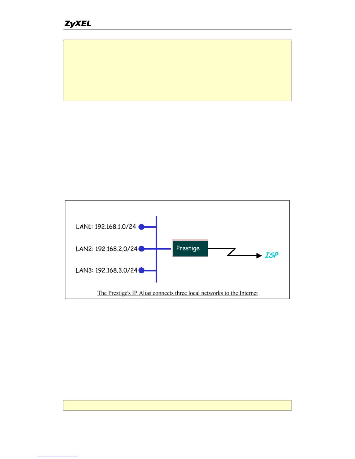
P-660 series Support Notes
Jul 19 11:43:43 192.168.1.1 ZyXEL Communications Corp.: ppp:IPCP Opening
Jul 19 11:43:51 192.168.1.1 ZyXEL Communications Corp.: ppp:CCP Opening
Jul 19 11:43:55 192.168.1.1 ZyXEL Communications Corp.: ppp:BACP Opening
Jul 19 11:44:00 192.168.1.1 ZyXEL Communications Corp.: ppp:LCP Closing
Jul 19 11:44:05 192.168.1.1 ZyXEL Communications Corp.: ppp:IPCP Closing
Jul 19 11 mmunications Corp.: ppp:CCP Closing :44:09 192.168.1.1 ZyXEL Co
Jul 19 1 munications Corp.: ppp:BACP Closing 1:44:14 192.168.1.1 ZyXEL Com
10. Using IP Alias
• What is IP Alias ?
In a typical environment, a LAN router is required to connect two local networks
P-660 can connect three local networks
. The
to the ISP or a remote node, we call this
function as 'IP Alias'. In this case, an internal router is not required. For example, the
network manager can divide the local network into three networks and connect them
to the Internet using P-660's single user account. See the figure below.
The P-660 supports three virtual LAN interfaces via i
interface. The first network can be configured in men
third networks that we call 'IP Alias 1' and 'IP Alias
3.2.1-IP Alias Setup.
There are three internal virtual LAN interfaces for the
fro
for
ts single physical Ethernet
u 3.2 as usual. The second and
2' can be configured in menu
P-660 to route the packets
m/to the three networks correctly. They are enif0 for the major network, enif0:0
the IP alias 1 and enif0:1 for the IP alias 2. Therefore, three routes are created in
the P-660 as shown below when the three networks are configured. If the P-660's
n be any of the three networks. DHCP is also enabled, the IP pool for the clients ca
Copyright (c) 1994 - 2005 ZyXEL Communications Corp.
92
All contents copyright © 2005 ZyXEL Communications Corporation.
Page 94
P-660 series Support Notes
ras> ip ro st
Dest FF Len Interface Gateway Metric stat Timer Use
192.168.3.0 00 24 enif0:1 192.168.3.1 1 041b 0 0
192.168.2.0 00 24 enif0:0 192.168.2.1 1 041b 0 0
192.168.1.0 00 24 enif0 192.168.1.1 1 041b 0 0
ras>
Two new protocol filter interfaces in menu 3.2.1 allow you to accept or deny LAN
through the P-660. The filter set in
menu 3.1 is used for main network configured in menu 3.2.
p
menu 3.2 by configuring the P-660's first LAN IP
packets from/to the IP alias 1 and IP alias 2 go
• IP Alias Setu
1. Edit the first network in
address.
Menu 3.2 - TCP/IP and DHCP Setup
DHCP Setup
DHCP= Server
Client IP Pool Starting Address= 192.168.1.33
Size of Client IP Pool= 6
Primary DNS Server= 168.95.1.1
Secondary DNS Server= 168.95.192.1
Remote DHCP Server= N/A
TCP/IP Setup:
IP Address= 192.168.1.1
IP Subnet Mask= 255.255.255.0
RIP Direction= Both
Version= RIP-1
Multicast= None
IP Policies=
Edit IP Alias= Yes
Press ENTER to Confirm or ESC to Cancel:
Key Settings:
DHCP
Setup
If the P-660's DHCP s
three networks.
erver is enabled, the IP pool for the clients can be any of the
TCP/IP
Setup
Enter the first LAN IP address for the P-660. Th
enif0 interface.
is will create the first route in the
93
All contents copyright © 2005 ZyXEL Communications Corporation.
Page 95
P-660 series Support Notes
Edit IP
Alias
Toggle to 'Yes' to enter menu 3.2.1 for setting up the second and third networks.
2. Edit the second and third networks in menu 3.2.1 by configuring the P-660's second
and third LAN IP addresses.
Menu 3.2.1 - IP Alias Setup
IP Alias 1= Yes
IP Address= 192.168.2.1
IP Subnet Mask= 255.255.255.0
RIP Direction= None
Version= RIP-1
Incoming protocol filters=
Outgoing protocol filters=
IP Alias 2= Yes
IP Address= 192.168.3.1
IP Subnet Mask= 255.255.255.0
RIP Direction= None
Version= RIP-1
Incoming protocol filters=
Outgoing protocol filters=
Enter here to CONFIRM or ESC to CANCEL:
Key Settings:
IP Alias 1
Toggle to 'Yes' an
create the second route in
d enter the second LAN IP address for the P-660. This will
the enif0:0 interface.
IP Alias 2
Toggle to 'Ye
the third ro
s' and enter the third LAN IP address for the P-660. This will create
ute in the enif0:1 interface.
uting
11. Using IP Policy Ro
• What is IP Policy Routing (IPPR)?
94
All contents copyright © 2005 ZyXEL Communications Corporation.
Page 96
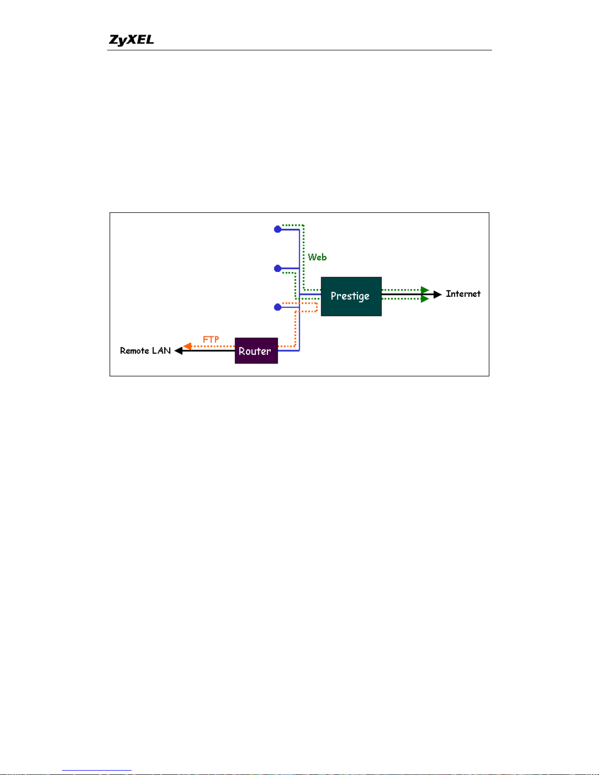
P-660 series Support Notes
raditionally, routing is based on the destination address only and the router takes the
hortest path to forward a packet. IP Policy Routing (IPPR) provides a mechanism to
forwarding based on the
policy defined by the network administrator. Policy-based routing is applied to
ior to the normal routing. Network
paths. For example, if
mote node connections, we can route the Web
y and route the FTP packets to the remote LAN
e figure below.
T
s
override the default routing behavior and alter the packet
incoming packets on a per interface basis, pr
administrators can use IPPR to distribute traffic among multiple
a network has both the Internet and re
packets to the Internet using one polic
using another policy. See th
Use IPPR to distribute traffic among multiple paths
tting the
f the
network to enable the backbone to prioritize traffic.
Cost Savings- IPPR allows organizations to distribute interactive traffic on
hig a g low-path for batch traffic.
rs can use IPPR to distribute traffic among
multiple paths.
• How does the IPPR work?
policy defines the matching criteria and the action to take when a packet meets the
n all the criteria are met. The criteria include the
source address and port, IP protocol (ICMP, UDP, TCP,etc), destination address and
• Benefits
Source-Based Routing - Network administrators can use policy-based routing to
direct traffic from different users through different connections.
Quality of Service (QoS)- Organizations can differentiate traffic by se
precedence or TOS (Type of Service) values in the IP header at the periphery o
h-b ndwidth, high-cost path while usin
Load Sharing- Network administrato
A
criteria. The action is taken only whe
95
All contents copyright © 2005 ZyXEL Communications Corporation.
Page 97

P-660 series Support Notes
ort, TOS and precedence (fields in the IP header) and length. The inclusion of
tive and bulk traffic. Interactive
hile bulk traffic, e.g., file
ket to a different gateway (and
nce fields in the IP header.
y of ZyNOS in style and in
re divided into sets, where related policies are grouped
olicies before applying them to an interface or a remote
s. There are 12 policy sets with 6 policies in
• Setup the IP Policy Routing
p
length criterion is to differentiate between interac
applications, e.g., Telnet, tend to have short packets, w
transfer, tends to have large packets.
The actions that can be taken include routing the pac
hence the outgoing interface) and the TOS and precede
IPPR follows the existing packet filtering facilit
implementation. The policies a
together. A use defines the p
node, in the same fashion as the filter
each set.
1. Create a routing policy set in menu 25
Menu 25 - IP Routing Policy Setup
Policy Policy
Set # Name Set # Name
------ ---------------- - ------ -----------------
1 _______________ 7 _______________
2 _______________ 8 _______________
3 _______________ 9 _______________
4 _______________ 10 _______________
5 _______________ 11 _______________
6 _______________ 12 _______________
Enter Policy Set Number to Configure= 1
Edit Name= policy1
Press ENTER to Confirm or ESC to Cancel:
2. Edit a rule or more for this set in m enu 25.1.1. See an example below.
Menu 25.1.1 - IP Routing Policy
Policy Set Name= First
Active= Yes
96
All contents copyright © 2005 ZyXEL Communications Corporation.
Page 98

P-660 series Support Notes
Criteria:
IP Protocol = 6
Type of Service= Don't Care Packet length= 0
Precedence = Don't Care Len Comp= N/A
Source:
addr start= 192.168.1.2 end= 192.168.1.20
port start= 0 end= N/A
Destination:
addr start= 0.0.0.0 end= N/A
port start= 80 end= 80
Action= Matched
Gateway addr = 192.168.1.254 Log= No
Type of Service= No Change
Precedence = No Change
Press ENTER to Confirm or ESC to Cancel
This policy exam the Web packets originated from the clients with IP
addresses from 1
2.168
umm
ple forces
92.168.1.2 to 192.168.1.20 be routed to the remote LAN via the
.1.254. gateway 19
4. A s ary for this set is shown in menu 25.1.
Men up u 25.1 - IP Routing Policy Set
# A Criteria/Action
- - ---------------------------------------------- ---------------------------
1 Y SA=192.168.1.2-192.168.1.20
DP=80-80 P=6 |GW=192.168.1.254
2 N ___________ ________________ ___________ _________________________ ___________
__________________________________________________________________________
3 N ___ __________________________ _____ ________________________ ________________
____ __________________________ ______ ___________________________ ___________
4 N _______________________ ___________________________________________________
__________________________________________________________________________
5 N _______________________ ___________________________________________________
__________________________________________________________________________
6 N _______________________ ___________________________________________________
__________________________________________________________________________
Enter Policy Rule Number (1-6) to Configure:
97
All contents copyright © 2005 ZyXEL Communications Corporation.
Page 99

P-660 series Support Notes
4. There are two interfaces to apply the policy set, they are the LAN inte
3.2) and WAN interface (menu 11.3). It depends where the gateway speci
policy rule is located. If the gateway you specified is located on
apply the policy set in menu 3.2 (LAN interface). If the gateway you specifi
located on the remote WAN site you apply the policy set in men
interface).
rface (menu
fied in the
the local LAN you
ed is
u 11.3 (WAN
Menu 3.2 - TCP/IP and DHCP Setup
CDH P Setup
DHCP= Server
Client IP Pool Starting Address= 192.168.1.33
Size of Client IP Pool= 32
Primary DNS Server= 0.0.0.0
Secondary DNS Server= 0.0.0.0
Remote DHCP Server= N/A
TCP/IP Setup:
IP Address= 192.168.1.1
IP Subnet Mask= 255.255.255.0
RIP Direction= Both
Version= RIP-1
Multicast= None
IP Policies= 1
Edit IP Alias= No
Press ENTER to Confirm or ESC to Cancel:
Menu 11.3 - Remote Node Network Layer Options
IP Options: Bridge Options:
Rem IP Addr: Ethernet Addr Timeout(min)= N/A
Rem Subnet Mask= 0.0.0.0
My WAN Addr= 0.0.0.0
NAT = None
Address Mapping Set= N/A
98
All contents copyright © 2005 ZyXEL Communications Corporation.
Page 100

P-660 series Support Notes
Metric= 2
Private= No
RIP Direction= Both
Version= RIP-2B
Multicast= IGMP-v2
IP Policies= 1
Enter here to CONFIRM or ESC to CANCEL:
e
rding to the pre-defined schedule. This feature is just like the
scheduler ina video recorder which records the program according to the specified
p), and
Down", "Enable
Dial-On-Demand", or "Disable Dial-On-Demand" on specified date and time.
• SMT Menu for Call Scheduling
. Edit the Schedule sets in menu 26:
12. Using Call Scheduling
• What is Call Scheduling ?
Call scheduling enables the mechanism for the P-660 to run the remote nod
connection acco
time. Users can apply at most 4 schedule sets in Menu 11 (Remote Node Setu
configure each schedule in Menu 26(Schedule Setup). The remote node configured
with the schedule set could be "Forced On", "Forced
1
Copyright (c) 1994 - 2005 ZyXEL Communications Corp.
Prestige 660 Main Menu
Getting Started Advanced Management
1. General Setup 21. Filter Set Configuration
2. WAN Backup Setup 22. SNMP Configuration
3. LAN Setup 23. System Password
4. Internet Access Setup 24. System Maintenance
25. IP Routing Policy Setup
Advanced Applications 26. Schedule Setup
11. Remote Node Setup
12. Static Routing Setup
99
All contents copyright © 2005 ZyXEL Communications Corporation.
 Loading...