

Zytronic ZXY150, ZXY200, ZXY300, ZXY500 Integration Manual

PROJECTED CAPACITIVE
MULTI TOUCH CONTROLLER & SENSOR
INTEGRATION MANUAL
ISSUE 3
ZXY150/200/300/500

ZYTRONIC PROJECTED CAPACITIVE MULTI TOUCH
CONTROLLER & SENSOR
INTEGRATION MANUAL ISSUE 3
CHAPTER TITLE PAGES
1.0 Introduction 5
2.0 Integrating the Sensor 7–9
3.0 Integrating the Controller PCB 11–13
4.0 Routing the Sensor Flexible Cables 15–19
5.0 Power and Data Connections 21–25
6.0 Using a Bezel 27
7.0 Integration Checks 29
8.0 Controller PCB Drawings 31–36
9.0 Further Information 37

PG 3
ZYTRONIC PROJECTED CAPACITIVE TOUCH CONTROLLER & SENSORINTEGRATION MANUAL ISSUE 3
ZYTRONIC
USER MANUAL ISSUE RECORD
ISSUE NUMBER
Issue 3
RELEASE DATE
20 July 2018
COMMENTS
Disclaimer added to Integration section regarding modication of exible cable joint
EXPLANATION OF SYMBOLS USED
WITHIN THIS MANUAL
Warning Hazardous Voltage.
Caution - item is susceptible to electrostatic discharge (ESD) damage
if proper precautions are not taken.
Warning - modication may result in invalidation of the Zytronic warranty

1.
INTRODUCTION
PG 5
ZYTRONIC PROJECTED CAPACITIVE TOUCH CONTROLLER & SENSORINTEGRATION MANUAL ISSUE 3
ZYTRONIC
INTRODUCTION
SHIPPING DAMAGE
On receipt of your Zytronic Projected Capacitive Multi Touch Controller Touchscreen Product, if you notice
damage to the shipping carton, or concealed damage, be sure to save all packing materials for later inspection
by the carrier, who is responsible for any shipping damage.
WARRANTY
If failure occurs during the warranty period of the product, please contact the point of sale
from which the product was purchased.
CARE AND CLEANING
Handle the touchscreen with care prior to and during installation. Do not pull or stress
the cables/exible cables and ensure no damage is caused to the touchscreen prior to
installation. Clean the touchscreen surfaces with a glass cleaning solution and soft lint-free
cloth. Ensure that the surfaces are clean and dry before integration of the touchscreen.
Industry standard Anti-static procedures for electronic equipment must be followed when
handling the touchscreen sensor and controller PCB during all stages of unpacking and
installation of the product to prevent damage to the product due to high levels of ESD.
UNPACKING YOUR TOUCHSCREEN
Ensure that the following items are present and in good condition:
Zytronic Projected Capacitive Multi Touch Controller(s) and
touchscreen sensor(s).
Users can download the latest Zytronic Projected Capacitive Multi Touch Controller Touchscreen Conguration
Software and User Manual directly from the Zytronic website. www.zytronic.co.uk/support
BEFORE YOU BEGIN
Before proceeding with the touchscreen installation ensure the following:
• Your Windows operating system is correctly installed and operating with your mouse.
• Ensure that all other touchscreen manufactures Driver Software/old touchscreen
Driver software is uninstalled from the host computer to avoid software conicts.
• Ensure that there is a free USB port available on the host computer to connect the desired Zytronic Projected
Capacitive Multi Touch Controller Touchscreen.
• Ensure that Industry standard Anti-static procedures for electronic equipment are
followed during unpacking and installation of the product.

2.
INTEGRATING
THE SENSOR

PG 7
ZYTRONIC PROJECTED CAPACITIVE TOUCH CONTROLLER & SENSORINTEGRATION MANUAL ISSUE 3
ZYTRONIC
INTEGRATING THE SENSOR
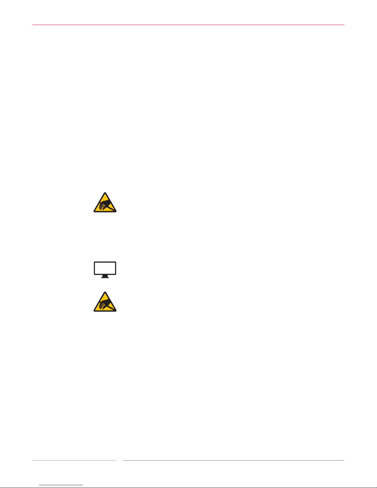
To integrate the sensor, you will require a suitably sized LCD with a display area matching the
active area of the sensor, as shown in Figure 1 (the active area of the sensor can be found on
the corresponding Zytronic sensor drawing).
FIGURE 1
SUITABLE LCD TO MOUNT THE SENSOR TO
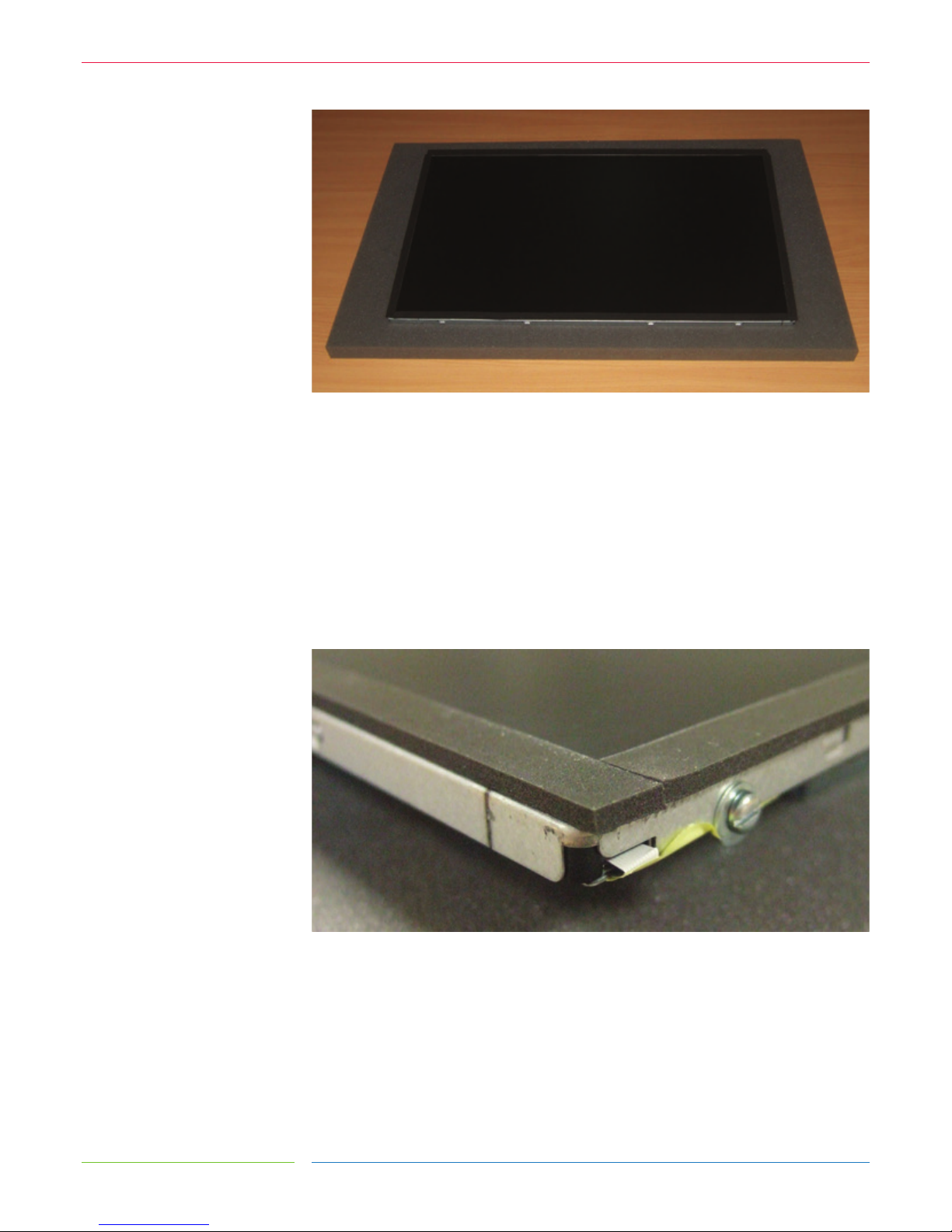
Foam gasket should be used around the perimeter of the LCD to provide an air gap between
the LCD face and the rear of the sensor, as shown in Figure 2. This air gap is necessary to
prevent excessive electrical noise from the LCD causing interference to the sensor. Guidelines
for the required thickness of the gasket can be seen in the table below and are sucient for
most LCDs. Some LCDs with very high levels of noise may require greater spacing which
would need to be determined by testing.
SENSOR SIZE GASKET THICKNESS
5 – 22˝ 3mm
22 – 32˝ 4mm
32 – 46˝ 6mm
PG 8
ZYTRONIC PROJECTED CAPACITIVE TOUCH CONTROLLER & SENSORINTEGRATION MANUAL ISSUE 3
ZYTRONIC
FIGURE 2
FOAM GASKET APPLIED TO LCD TO PROVIDE AIR GAP BETWEEN LCD AND SENSOR
If the sensor is only to be tted to the LCD temporarily and kept horizontal, a single sided,
electrically non-conductive, low performance gasket can be used, such as EPDM (Ethylene
Propylene Diene Monomer) foam sealing strip, as shown in Figure 3. For permanent
applications, or where the weight of the sensor is to be held only by the gasket, a higher
performance gasket such as 3M VHB tape can be used. This will normally require the gasket
to be built up to the correct thickness with several layers.
Dierent VHB tapes are available depending on the material of the surfaces it is adhering to.
Any gasket used must be non-sulphurous and maintain its adhesion at any temperature that
it may be subjected to in service.
FIGURE 3
GASKET APPLIED TO THE LCD PERIMETER
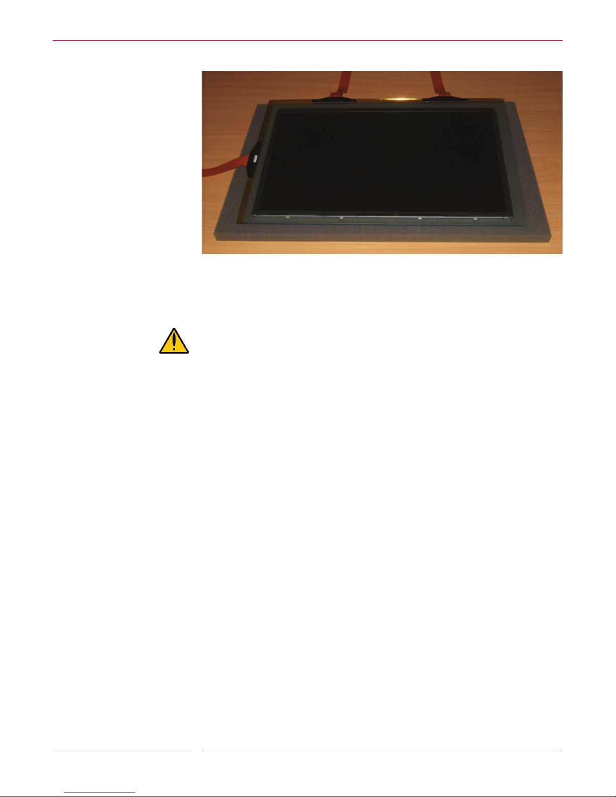
The sensor should be positioned on the LCD with the sensor active area (as dened on the
Zytronic product drawing) matched to the LCD display area. The glass face (with ‘Viewing
Face’ label) should be visible, as shown in Figure 4. The sensor can be positioned as shown
or rotated by 180 degrees (so that the exible cables are on the bottom and right edges).
The position should be chosen which gives the best clearance for mounting the controller
PCB on the rear on the LCD. If required, the sensor can be cleaned on the front (glass) face
and rear (polyester) face with a glass cleaning solution and a soft lint-free cloth.
PG 9
ZYTRONIC PROJECTED CAPACITIVE TOUCH CONTROLLER & SENSORINTEGRATION MANUAL ISSUE 3
ZYTRONIC
FIGURE 4
SENSOR MOUNTED ONTO LCD WITH GASKET
Zytronic do not recommend the application of gasket, sealants or adhesives directly over the exible cable joint
area of the touch sensor, or the modication/removal of the pre-applied strengthening tape at the joint. Any
evidence of such modication may result in invalidation of the Zytronic warranty. If you have any questions
regarding this subject, please contact Zytronic Technical Suppor t for further advice: http://zytronic.co.uk/
support/

3.
INTEGRATING THE
CONTROLLER PCB
PG 11
ZYTRONIC PROJECTED CAPACITIVE TOUCH CONTROLLER & SENSORINTEGRATION MANUAL ISSUE 3
ZYTRONIC
INTEGRATING THE CONTROLLER PCB
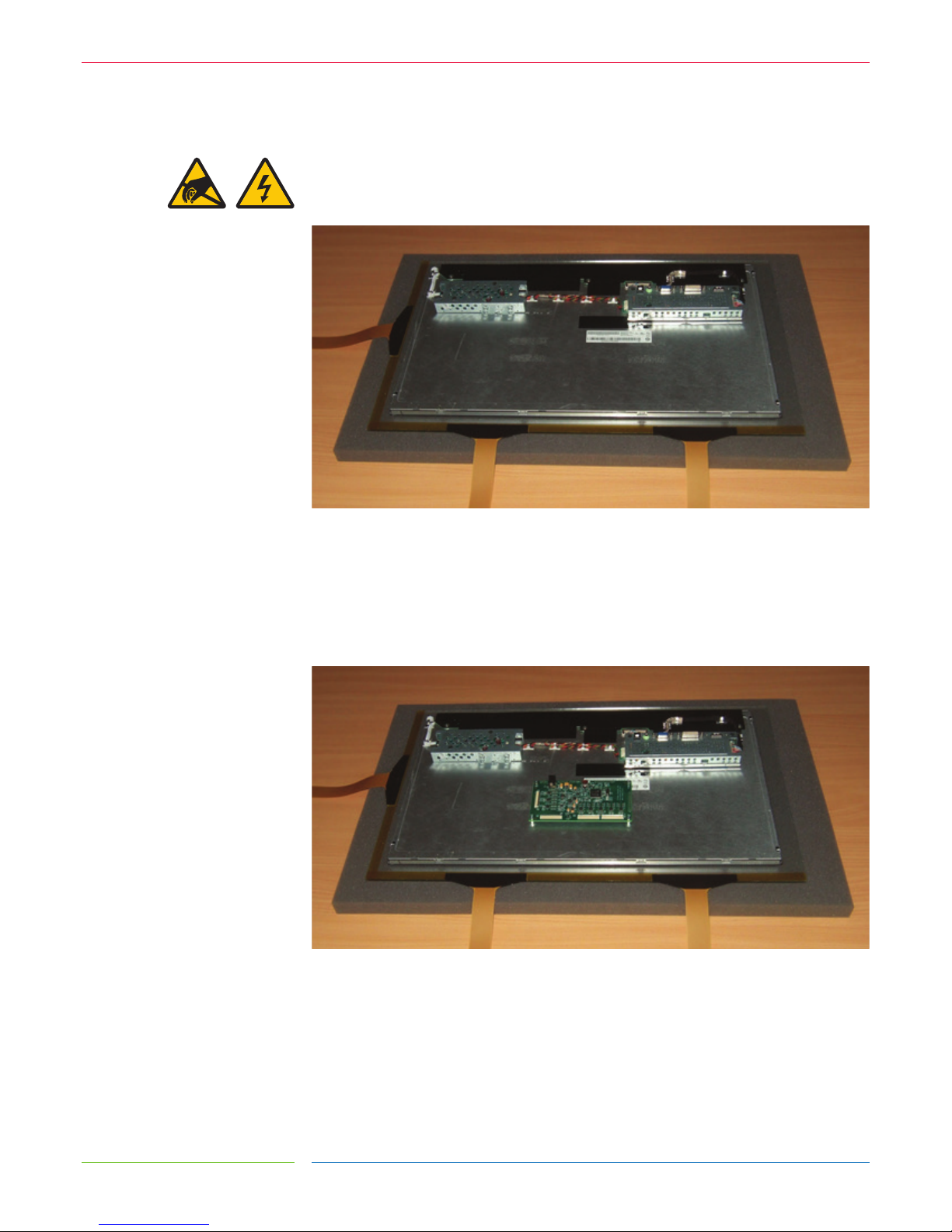
The components on the rear of the LCD should be arranged to allow a suitable space for the
controller PCB, as shown in Figure 5.
FIGURE 5
REAR OF LCD READY FOR CONTROLLER MOUNTING
The controller PCB should be positioned so that all three exible cables from the sensor can
comfortably reach their respective ZIF sockets without crossing over other cables or PCBs.
There should also be sucient space around the power and USB sockets to attach the
cables. Ideally avoid placing the controller within ~30mm of other PCBs and cables, as shown
in Figure 6.
FIGURE 6
CONTROLLER POSITION ON REAR OF LCD
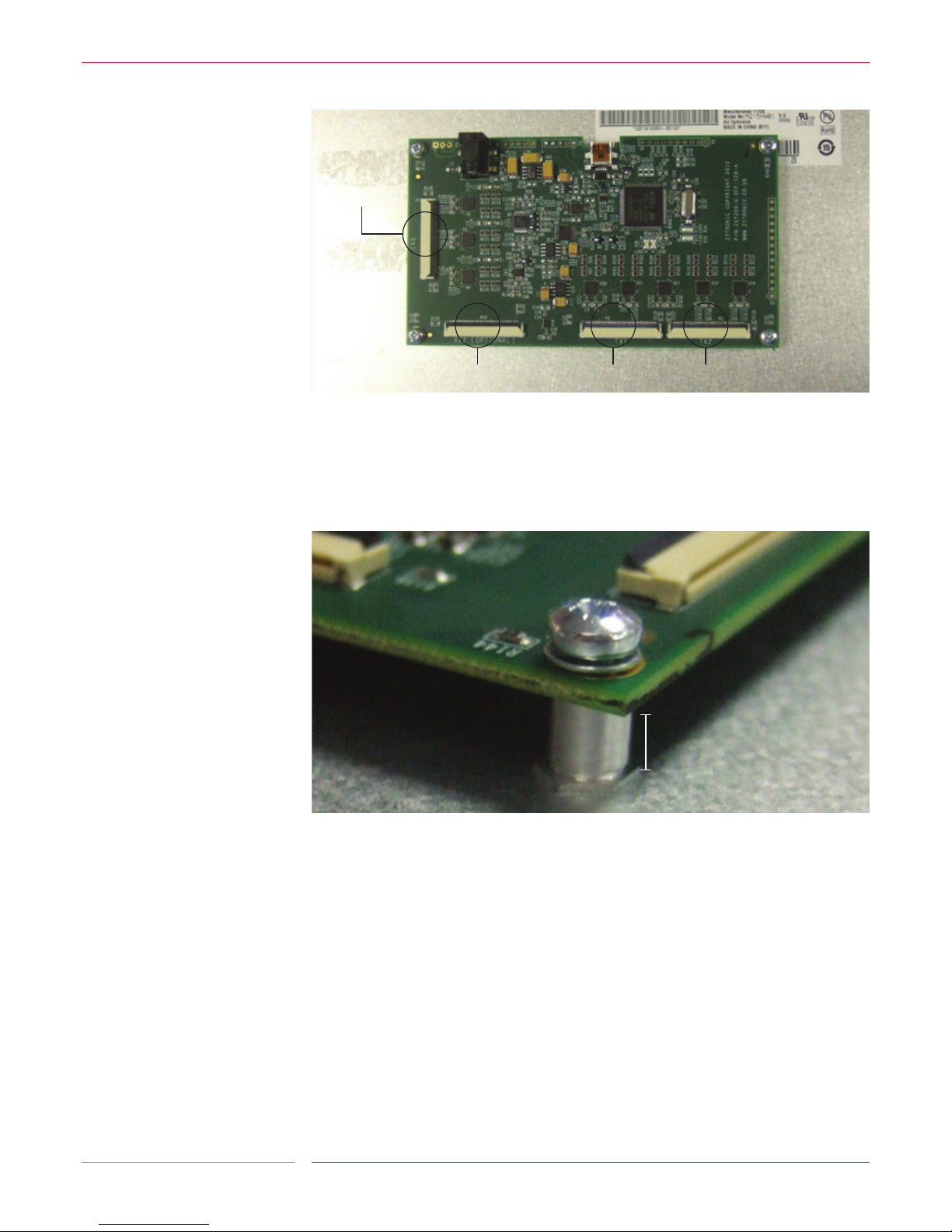
The Flexible cables plug into the ZIF sockets as shown in Figure 7. When viewing from the
rear of the LCD with the sensor orientated as shown in Figure 6, the exible cable attached
to the left of the long edge of the sensor should connect to Transmit 1, and the exible cable
attached to the right of the long edge of the sensor should connect to Transmit 2. The single
exible cable attached to the short edge of the sensor should connect to Receive 1. No
connection should be made to Receive 2 for standard sensor designs.
PG 12
ZYTRONIC PROJECTED CAPACITIVE TOUCH CONTROLLER & SENSORINTEGRATION MANUAL ISSUE 3
ZYTRONIC
FIGURE 7
CONTROLLER PCB
The controller should ideally be mounted to four metal standos pre-tted to the metal
chassis so that there is a good low impedance ground connection between the controller
PCB and LCD metal chassis, as shown in Figure 8. The controller PCB should be spaced at
least 5mm away from the metal chassis.
FIGURE 8
CONTROLLER SPACED 5MM ABOVE METAL WORK AND GROUNDED TO METAL CHASSIS
VIA METAL STANDOFFS
If mounting via metal standos is not possible, double sided gasket pads can be used.
The controller PCB should still be spaced at least 5mm away from the mounting surface,
as shown in Figure 9. Any gasket used must maintain its adhesion at any temperature that
it may be subjected to in service.
RECEIVE 2 RX2 OPTIONAL
RECEIVE 1 RX1
TRANSMIT 1 TX1 TRANSMIT 2 TX2
MINIMUM 5MM GAP
 Loading...