

Zytronic ZXY100 Integration Manual

PROJECTED CAPACITIVE ZXY100®
TOUCH CONTROLLER & SENSOR
INTEGRATION MANUAL
VERSION 1.1
ZXY100

PG 2
ZYTRONIC PROJECTED CAPACITIVE ZXY100/110® TOUCH CONTROLLER & SENSORINTEGRATION MANUAL ISSUE 1
ZYTRONIC
ZYTRONIC PROJECTED CAPACITIVE
ZXY100® TOUCH CONTROLLER & SENSOR
INTEGRATION MANUAL – ISSUE 1
CHAPTER TITLE PAGES
1.0 Introduction 5
2.0 Controller Variants 7–8
3.0 Integrating the Sensor 10–12
4.0 Integrating the Controller PCB 14–16
5.0 Attaching the Sensor Flexible Cables 18–20
6.0 Power and Data Connections 22–25
7.0 Using a Bezel 27
8.0 Integration Checks 29
9.0 Controller PCB Drawings 31–36
10.0 Serial Cable Drawing 38
11.0 Further Information 40
PG 3
ZYTRONIC PROJECTED CAPACITIVE ZXY100/110® TOUCH CONTROLLER & SENSORINTEGRATION MANUAL ISSUE 1
ZYTRONIC
USER MANUAL ISSUE RECORD
ISSUE NUMBER
Issue 1
RELEASE DATE
13th June 2013
COMMENTS
First Release
EXPLANATION OF SYMBOLS USED
WITHIN THIS MANUAL
Warning Hazardous Voltage.
Caution - item is susceptible to electrostatic discharge (ESD) damage
if proper precautions are not taken.

1.
INTRODUCTION
PG 5
ZYTRONIC PROJECTED CAPACITIVE ZXY100/110® TOUCH CONTROLLER & SENSORINTEGRATION MANUAL ISSUE 1
ZYTRONIC
INTRODUCTION
SHIPPING DAMAGE
On receipt of your Zytronic Projected Capacitive ZXY100® Touch Controller Touchscreen
Product, if you notice damage to the shipping carton, or concealed damage, be sure to save
all packing materials for later inspection by the carrier, who is responsible for any shipping
damage.
WARRANTY
If failure occurs during the warranty period of the product, please contact the point of sale
from which the product was purchased.
CARE AND CLEANING
Handle the touchscreen with care prior to and during installation. Do not pull or stress
cables/flexible cables and ensure no damage is caused to the touchscreen prior to
installation. Clean the touchscreen surfaces with a glass cleaning solution and soft lint-free
cloth. Ensure that the surfaces are clean and dry before integration of the touchscreen.
Industry standard Anti-static procedures for electronic equipment must be followed when
handling the touchscreen sensor and controller PCB during all stages of unpacking and
installation of the product to prevent damage to the product due to high levels of ESD.
UNPACKING YOUR TOUCHSCREEN
Ensure that the following items are present and in good condition:
Zytronic Projected Capacitive ZXY100® Touch Controller(s) and touchscreen sensor(s).
Users can download the latest Zytronic Projected Capacitive ZXY100® Touch Controller
Touchscreen Driver / Configuration Software and User Manual directly from the Zytronic
website. www.zytronic.co.uk/support
BEFORE YOU BEGIN
Before proceeding with the touchscreen installation ensure the following:
• Your Windows operating system is correctly installed and operating with your mouse.
• Ensure that all other touchscreen manufactures Driver Software/old touchscreen
Driver software is uninstalled from the host computer to avoid software conflicts.
• Ensure that there is a free USB or Serial port available on the host computer to connect
the desired Zytronic Projected Capacitive ZXY100® Touch Controller Touchscreen.
• Ensure that Industry standard Anti-static procedures for electronic equipment are
followed during unpacking and installation of the product.

2.
CONTROLLER
VARIANTS
PG 7
ZYTRONIC PROJECTED CAPACITIVE ZXY100/110® TOUCH CONTROLLER & SENSORINTEGRATION MANUAL ISSUE 1
ZYTRONIC
CONTROLLER VARIANTS
The Zytronic Projected Capacitive ZXY100® Touch Controller range consists of six distinct
variants. There are three different controller sizes suitable for different ranges of sensor sizes,
and each controller size is available in either USB or Serial versions.
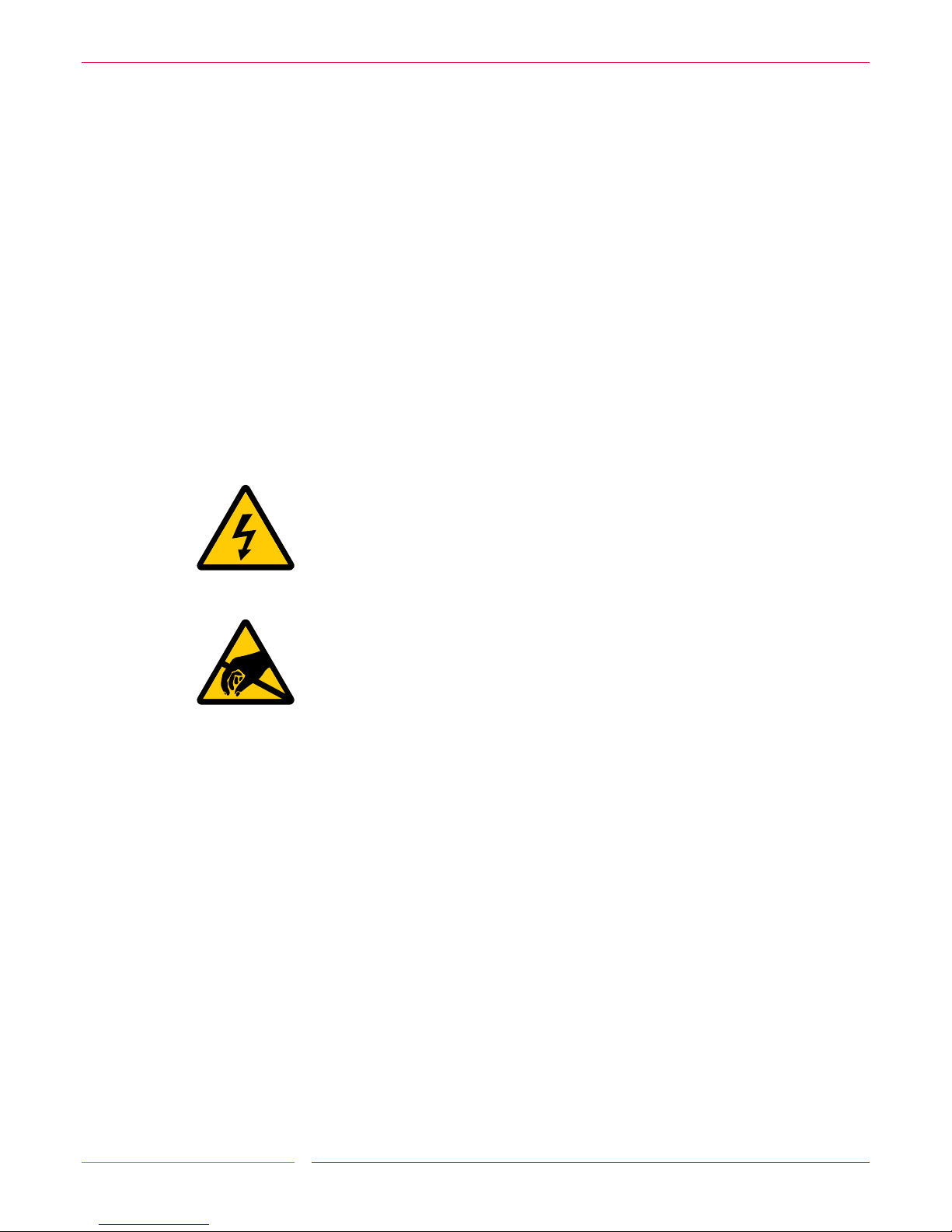
FIGURE 1
32 INPUT ZXY100® USB CONTROLLER FOR SMALL SENSOR SIZES
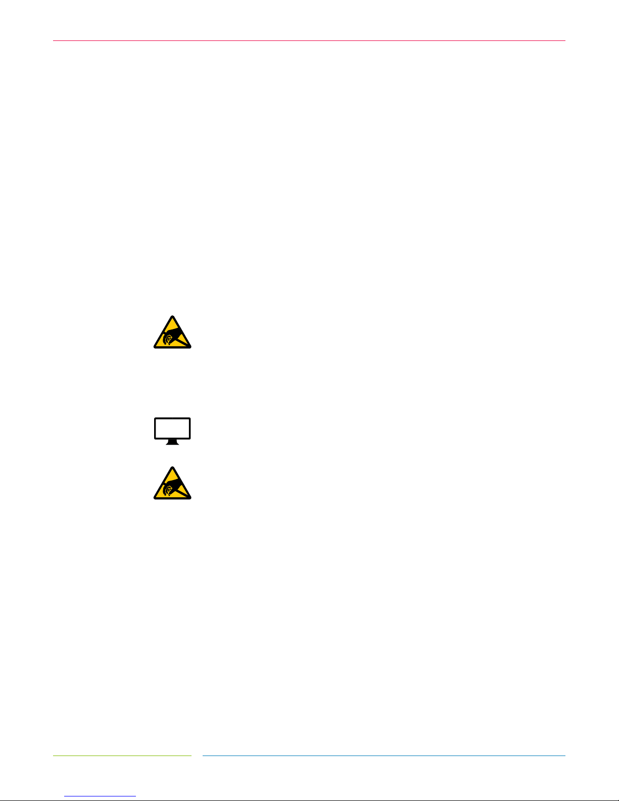
FIGURE 2
64 INPUT ZXY100/110® USB CONTROLLER FOR MEDIUM SENSOR SIZES
PG 8
ZYTRONIC PROJECTED CAPACITIVE ZXY100/110® TOUCH CONTROLLER & SENSORINTEGRATION MANUAL ISSUE 1
ZYTRONIC
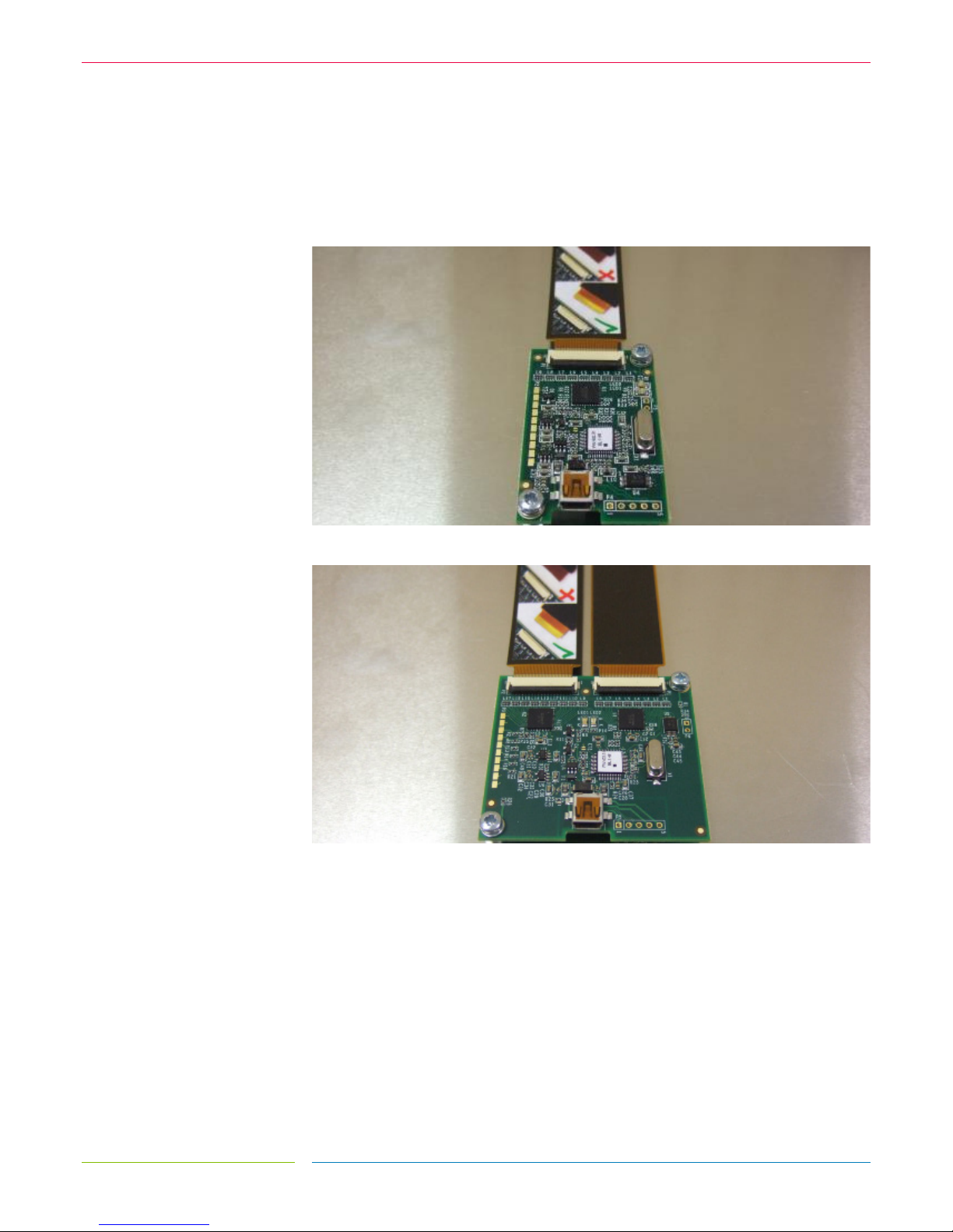
FIGURE 3
128 INPUT ZXY100® USB CONTROLLER FOR LARGE SENSOR SIZES
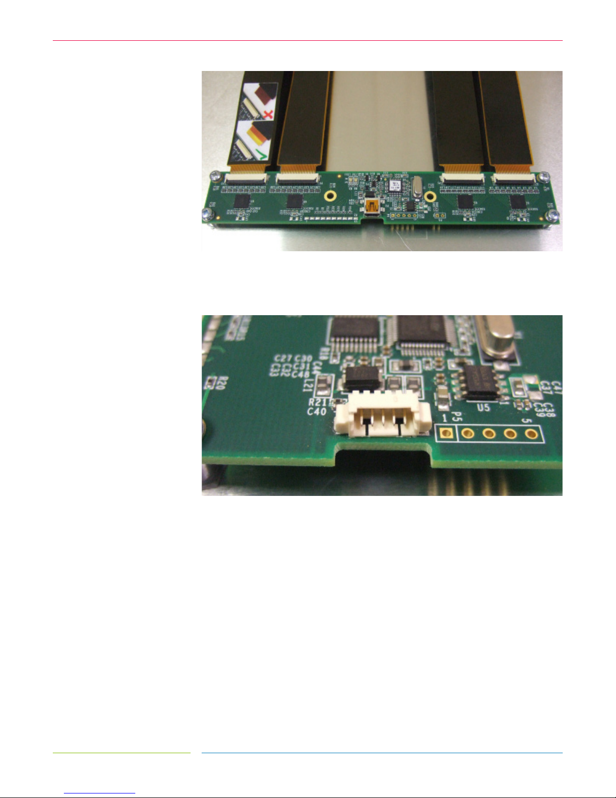
For USB versions, a USB cable with mini-B plug is required. Serial versions require a Serial
cable with a Molex type connector, as specified in the Serial Cable drawing in section 10.0.
FIGURE 4
MOLEX CONNECTOR USED ON SERIAL CONTROLLERS

3.
INTEGRATING
THE SENSWOR
PG 10
ZYTRONIC PROJECTED CAPACITIVE ZXY100/110® TOUCH CONTROLLER & SENSORINTEGRATION MANUAL ISSUE 1
ZYTRONIC
INTEGRATING THE SENSOR
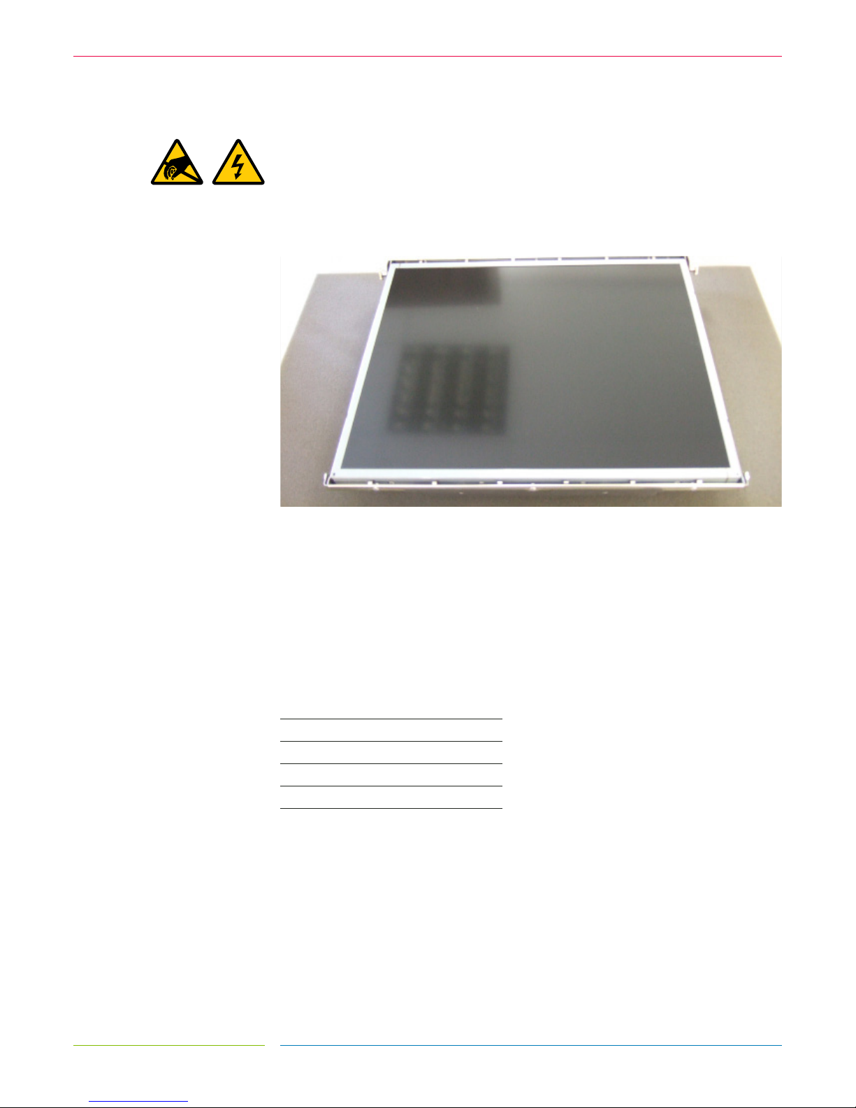
To integrate the sensor, you will require a suitably sized LCD with a display area close to the
active area of the sensor, as shown in Figure 5 (the active area of the sensor can be found on
the corresponding Zytronic sensor drawing). Where possible, it is advisable to have the
active area of the sensor 2-3 mm oversized on all four edges in relation to the LCD display
area. This will allow for some misalignment during integration.
FIGURE 5
SUITABLE LCD TO MOUNT THE SENSOR TO
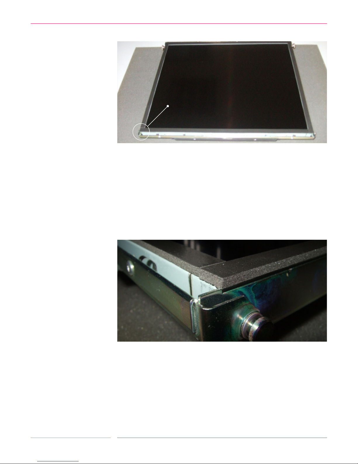
Foam gasket should be used around the perimeter of the LCD to provide an air gap between
the LCD face and the rear of the sensor, as shown in Figure 6. This air gap is necessary to
prevent excessive electrical noise from the LCD causing interference to the sensor.
Guidelines for the required thickness of the gasket can be seen in the table below and are
sufficient for most LCDs. Some LCDs with very high levels of noise may require greater
spacing which would need to be determined by testing.
SENSOR SIZE GASKET THICKNESS
5 – 22˝ 3mm
22 – 32˝ 4mm
32 – 46˝ 6mm
46 – 65˝ 8mm
65 – 84˝ 10mm
PG 11
ZYTRONIC PROJECTED CAPACITIVE ZXY100/110® TOUCH CONTROLLER & SENSORINTEGRATION MANUAL ISSUE 1
ZYTRONIC
FIGURE 6
FOAM GASKET APPLIED TO LCD TO PROVIDE AIR GAP BETWEEN LCD AND SENSOR
If the sensor is only to be fitted to the LCD temporarily and kept horizontal, a single sided,
electrically non-conductive, low performance gasket can be used, such as EPDM (Ethylene
Propylene Diene Monomer) foam sealing strip, as shown in Figure 7. For permanent
applications, or where the weight of the sensor is to be held only by the gasket, a higher
performance gasket such as 3M VHB tape can be used. This will normally require the gasket
to be built up to the correct thickness with several layers.
Different VHB tapes are available depending on the material of the surfaces it is adhering to.
Any gasket used must be non-sulphurous and maintain its adhesion at any temperature that
it may be subjected to in service.
FIGURE 7
GASKET APPLIED TO THE LCD PERIMETER
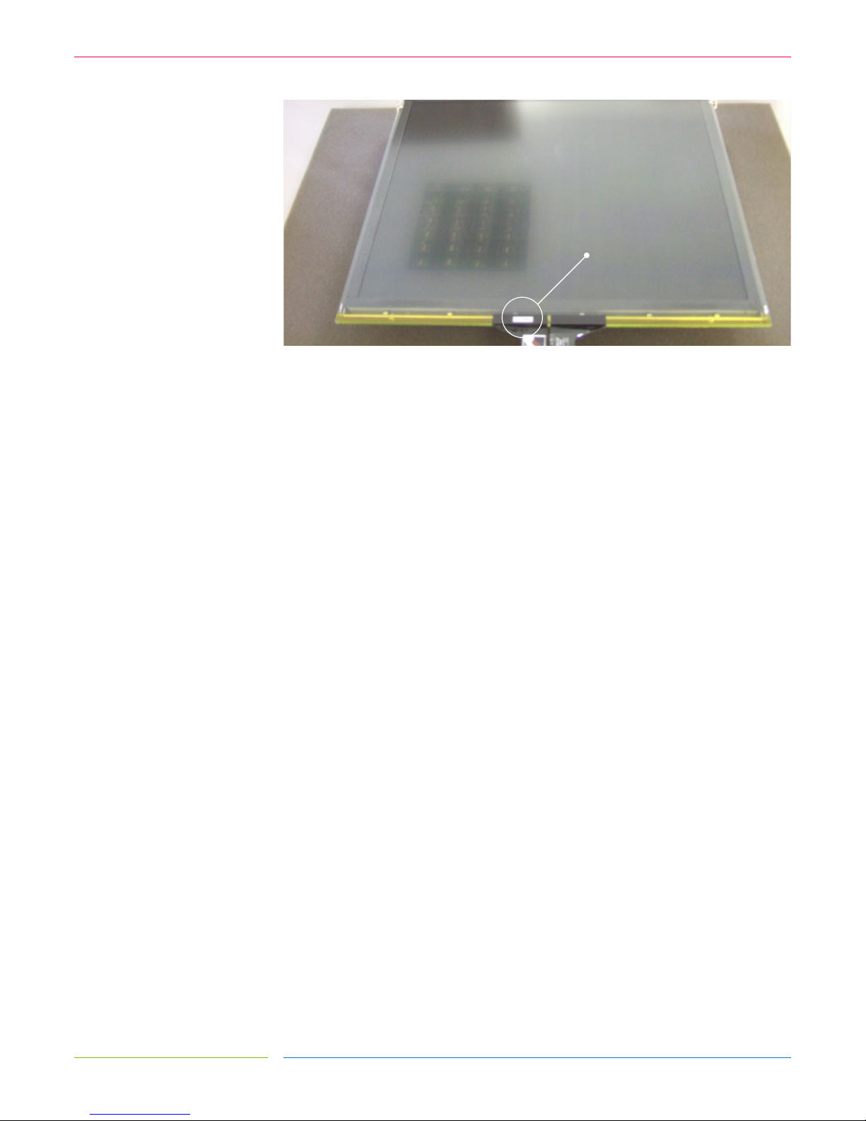
The sensor should be positioned on the LCD with the sensor active area (as defined on the
Zytronic product drawing) centred on the LCD display area. The glass face (with ‘Viewing
Face’ label) should be visible, as shown in Figure 8. The sensor can be positioned as shown or
rotated by 180 degrees (so that the flexible cables are on the top edge). The position should be
chosen which gives the best clearance for mounting the controller PCB on the rear of the LCD.
Sensor designs are also available with the flexible cables in alternative positions. If required, the
sensor can be cleaned on the front (glass) face and rear (polyester) face with a glass cleaning
solution and a soft lint-free cloth.
FOAM GASKET
PG 12
ZYTRONIC PROJECTED CAPACITIVE ZXY100/110® TOUCH CONTROLLER & SENSORINTEGRATION MANUAL ISSUE 1
ZYTRONIC
FIGURE 8
SENSOR MOUNTED ONTO LCD WITH GASKET
VIEWING FACE LABEL

4.
INTEGRATING THE
CONTROLLER PCB
 Loading...