

Page 1

KT-FX4 4-Input HD DVB-T Digital Modulator
User Guide and Install Manual
TABLE OF CONTENTS
Safety Precautions ........................................................................................................... 2
Package Contents ............................................................................................................ 2
Product Description ......................................................................................................... 3
Features .......................................................................................................................... 3
Specifications .................................................................................................................... 4
Installation ........................................................................................................................ 5
Unpacking and Inspection .................................................................................................................................................... 5
Hardware Installation and Connections ........................................................................................................................... 5
Power Supply Loss .................................................................................................................................................................... 5
Modulation Setup and Configuration via Front LCD .................................................................... 6
Device Programming and Setup ........................................................................................................................................... 6
Modulator Configuration ........................................................................................................................................................ 6
Reset to Default ........................................................................................................................................................................... 7
Modulation Setup and Configuration via GUI ............................................................................. 8
Connecting to the GUI Interface ........................................................................................................................................... 8
Overview .................................................................................................................................................................................................. 9
Encoder Setup ..................................................................................................................................................................................... 10
RF Output Setup ................................................................................................................................................................................. 12
Network Setup .................................................................................................................................................................................... 13
System Setup ....................................................................................................................................................................................... 13
Administration ................................................................................................................................................................................... 15
KT-FX4 HD Encoder/Modulator Notes ............................................................................16
1 KT-FX4 Manual V1.0
Page 2

Safety Precautions
The presence of this symbol is to alert the installer and user to the presence of
uninsulated dangerous voltages within the product’s enclosure that may be of sufficient
magnitude to produce a risk of electric shock.
TO REDUCE THE RISK OF FIRE OR ELECTRIC SHOCK, DO NOT EXPOSE THIS DEVICE
TO RAIN OR MOISTURE. DO NOT OPEN THE UNIT. REFER SERVICING TO QUALIFIED
PERSONNEL ONLY.
DO NOT apply power to the unit until all connections have been made, all components have been
installed and all wiring has been properly terminated.
DO NOT terminate, change or uninstall any wiring without first disconnecting the unit’s power adapter
from the device.
This device is supplied with the appropriately rated 12VDC power supply with the center pin positive. The
use of any other power supply could cause damage and invalidate the manufacturer’s warranty.
DO NOT power on the unit until all cables and connections to the device have been properly connected.
The device should be installed in an environment consistent with its operating temperature specifications.
Placement next to heating devices and ducts is to be avoided as doing so may cause damage. The
device should not be placed in areas of high humidity.
DO NOT cover any of the device’s ventilation openings.
If the device has been in a cold environment allow it to warm to room temperature for at least 2 hours
before connecting power.
Package Contents
This package contains:
One KT-FX4 HD Digital Modulator
Two Power Supplies with Power Cords (one Main and one Stand By)
One Quick Install Manual
Inspect the package before starting installation to ensure there is no damage and all supplied contents are
present. Contact your distributor or dealer should the device be damaged, or package contents are
incomplete.
2 KT-FX4 Manual V1.0
Page 3
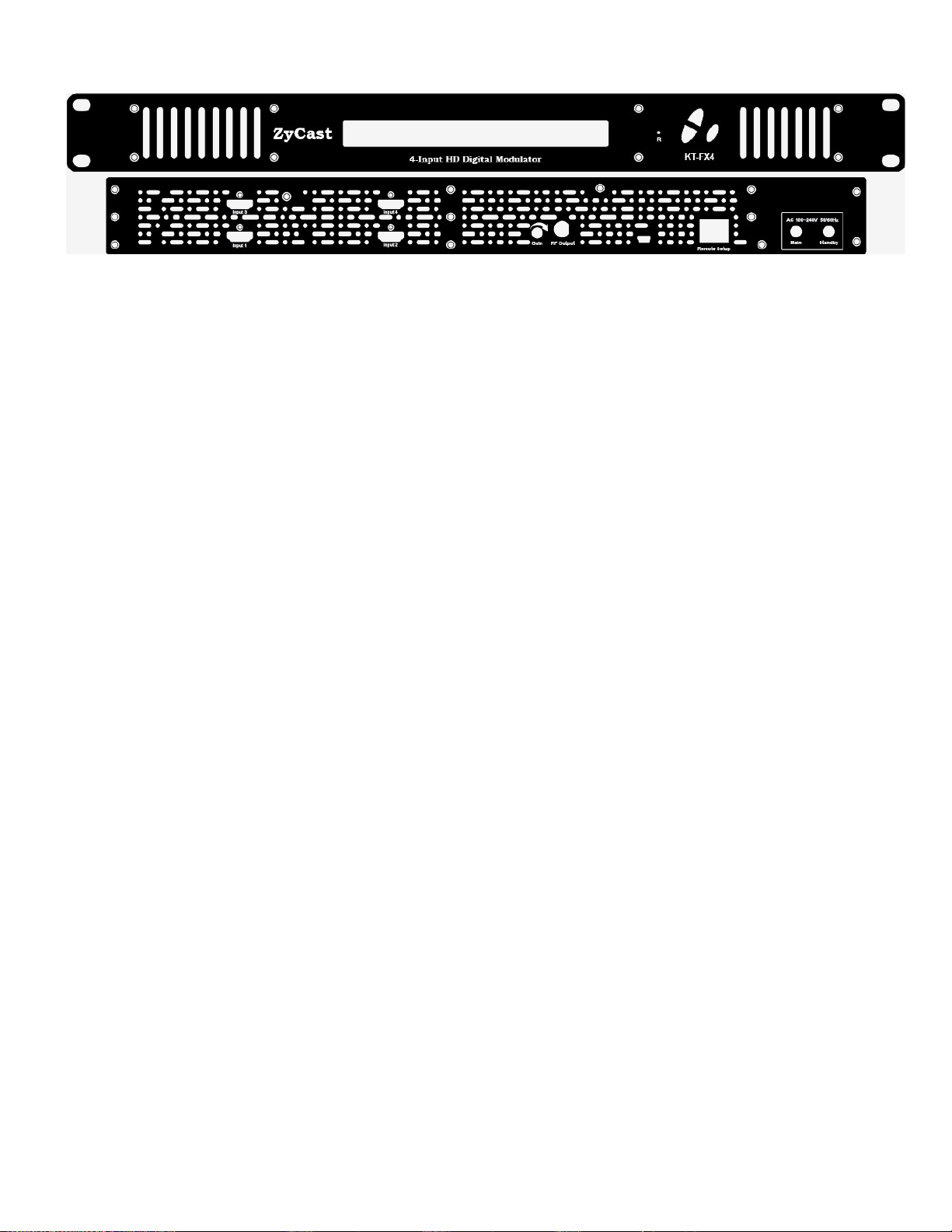
Product Description
ZyCast “KT-FX4” Modulator converts Digital Video Broadcasting (DVB) high definition video and
audio signals to COFDM.
KT-FX4 Digital Modulator is ideal for any Domestic or Commercial RF Network. The high-quality HD
design allows for watching action packed programs and sports channels on any HDTV. The space
saving design delivers up to 4 High Quality HD channels in a single 1RU space.
Features
☼ H.264 (MPEG-4) AVC Encoding
☼ 4 x HDMI Input, 1 x RF Output
☼ Preprogrammed with Approved Foxtel Channel numbers (refer list at the end of this manual)
☼ Automatically changes “clashing” settings when Channel ID is adjusted
☼ Gain Control (20dB Manual Attenuation)
☼ RJ-45 port for Web Management
☼ Video resolution: Up to 1080p
☼ Perfect, clean, and clear picture on high motion video, sports, text crawls/rolls, etc.
☼ Front panel LCD Display for easy installation
☼ Independent RF Output Channel per Encoder
☼ Rack mountable 1RU height
3 KT-FX4 Manual V1.0
Page 4
Specifications
Video / Audio Input
KT-FX4
Connectors
Audio
Quad, HDMI 1.4
Embedded PCM
OUTPUT
Standard DVB-T
Connector 1 x “F” Female
Frequency Range
Output Level
Flatness Across Full Band ±2dB
MER
Carrier (OFDM Mode)
Guard Intervals
Code Rate (FEC)
Modulation
Output Impedance
RF Output Return Loss
LCN
177.5 MHz to 816.5 MHz (Ch 6 to 69)
85 dBμV Typical
39 dB Typical
2K/8K
1/32
7/8
64QAM
75 ohm
10dB
AU(APN)
Video / Audio Encoding Profile
Video Resolution
Video Codecs
Audio Codecs
1080p / 1080i / 720p / 576p / 576i / 480p / 480i
H.264
MPEG1 Layer II / AAC
GENERAL
Local Monitoring LCD
Web GUI Supported IE, Firefox, Chrome, Safari
Password Protected GUI: Changeable
Power Supply
Consumption
Operating Temperature
Storage Temperature
Languages
Dimensions
Weight
External 12 VDC 5 Amp. or Equivalent / Redundant Power Supply
26W
0oC to +45oC
-10oC to +60oC
English
438mm x 206mm x 44mm
2.5kg
*Specifications subject to change without prior notice
4 KT-FX4 Manual V1.0
Page 5
Installation
System Installer must adhere to Article 820-40 of the NEC that provides guidelines for
proper grounding and specifies that the cable ground shall be connected to the
grounding system of the building, as close to the point of cable entry as possible.
Unpacking and Inspection
Each unit is shipped factory tested. Ensure all items are removed from the container prior to discarding any
packing material.
Thoroughly inspect the unit for shipping damage with particular attention to connectors and controls. If there
is any sign of damage to the unit or damaged or loose connectors contact your distributor immediately. Do
not put the equipment into service if there is any indication of defect or damage.
Hardware Installation and Connections
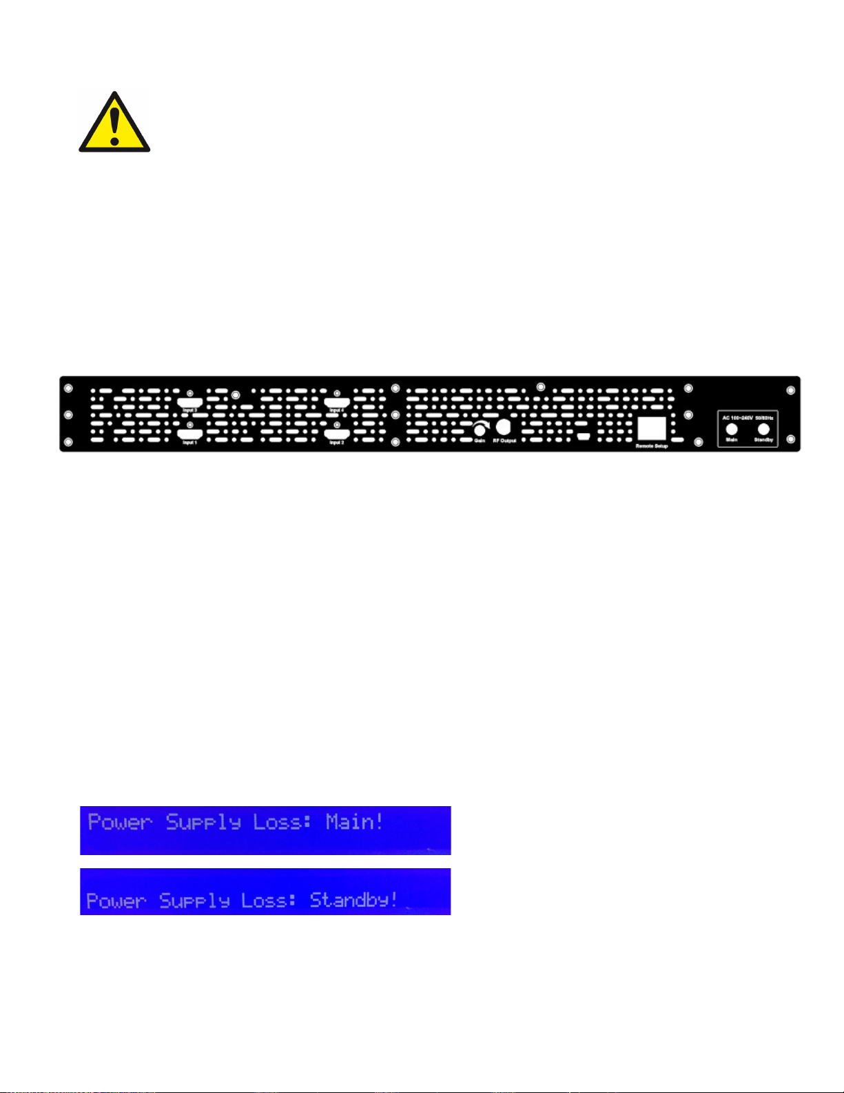
1. Use HDMI cables to connect the video sources (e.g., CATV, DVD, VCR, Camera) to the unit’s HDMI Input
port 1,2,3,4. It is highly recommended that quality HDMI cables be used for all video source connections.
2. Use a quality RJ45 cable to connect the Remote Setup port to a computer RJ45 port for setup/manage the
unit.
3. Connect the included power cords to the unit’s DC 12V POWER jacks (1 x Main & 1 x Stand By)
4. Connect the power supplies to an appropriately rated AC power outlet.
Power Supply Loss
Whenever there is a power supply issue - the LED Screen will show the Power Supply Loss message on
the screen and keep blinking to alert the user. If the modulator had enabled the SMTP function in the Web
Management Setup, it will send out the Power Supply Loss alert message to the setting email addresses.
(Please refer to Web Management Setup Page for the SMTP settings)
Once the issue has been rectified the screen will return to normal status
5 KT-FX4 Manual V1.0
Page 6
Modulation Setup and Configuration via Front LCD
Device Programming and Setup
To setup from the LCD Front Panel
KT-FX4 is designed to have an easy and simple settings from the LCD Front Panel
Modulator Configuration
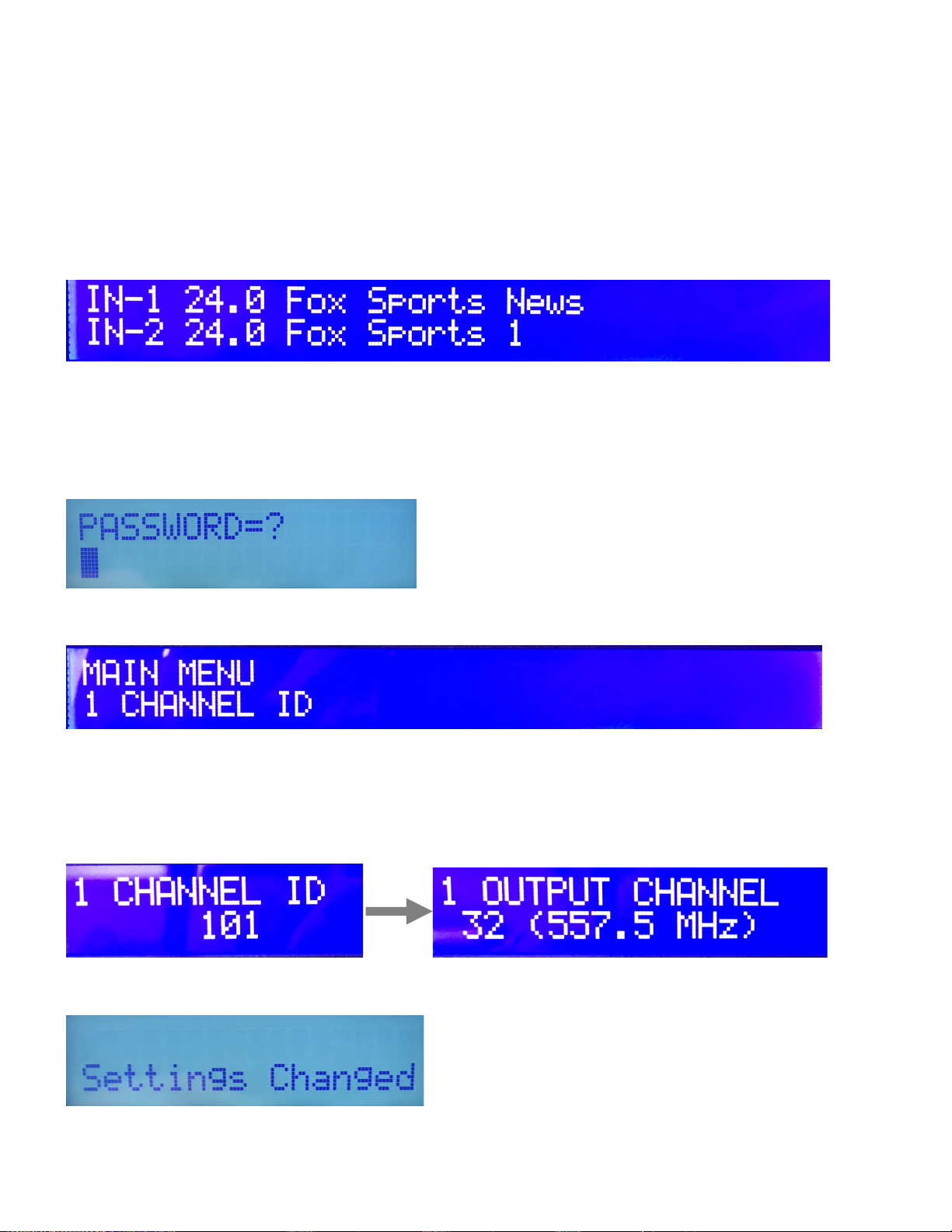
Once the modulator is powered up it will go through an internal booting process. When booting process
finished, the LCD Display shows the default Channel.
Main Menu – To access the Main Menu first enter the password by pressing the OK button. Use the Scroll
Up/Down buttons to enter the password. Once the password is entered press the OK button again and the
LCD Screen will display “Main Menu”.
Password – Use the Scroll Up/Down buttons to enter the password. Password is 0000. Press the OK button
for each number to enter the password. Press OK again after the display shows …... HD Series.
There are two parameters to setup, CHANNEL ID and OUTPUT CHANNEL. Press OK button it will show
MAIN MENU.
Press OK button to set the desired CHANNEL ID (see Foxtel Channel ID listing at the end of this manual),
then press OK to set the desired OUTPUT CHANNEL.
It is a must to set the CHANNEL ID and OUTPUT CHANNEL and press OK to finish the setting process,
otherwises the screen will keep on the CHANNEL ID/OUTPUT CHANNEL waiting for setting.
After OUTPUT CHANNEL setting finished, press OK button the screen will show Settings Changed, then go
back to the MAIN MENU. (Note: In 60 seconds, the screen will go back to the Channel information)
Note: Once these changes are made per modulator, all settingd associated will automatically change
6 KT-FX4 Manual V1.0
Page 7
Reset to Default
If you are ever required to reset the modulator from the front LCD screen back to the default settings, please
follow the below procedures.
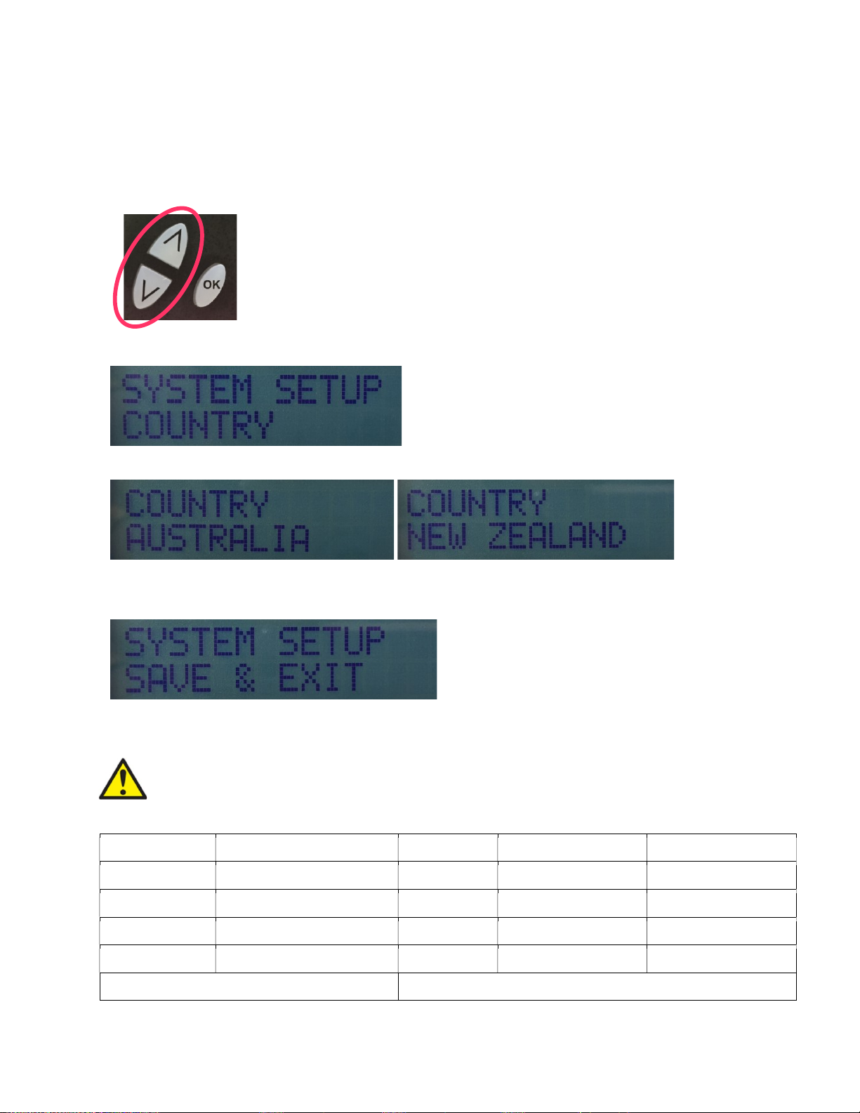
1. Turn OFF the unit. While pressing UP and DOWN buttons at the same time, power ON the unit.
2. Release the UP and DOWN buttons when the LCD shows Reset to Default.
3. Press OK button to select Country: Australia or New Zealand
4. Press OK button again when the country selected, then press UP or DOWN button to show
SAVE & EXIT.
5. Press OK button to Save and Exit. The unit will Booting on.
Caution: Once this process is complete the unit will automatically reset to the factory
default settings. All settings or changes to the encoder/modulator will be lost.
Input Channel Name LCN RF Output
Input 1 Fox Sports News 101 32 (557.5MHz)
Input 2 Fox Cricket 102 33 (564.5MHz)
Input 3 Fox League 103 34 (571.5MHz)
Input 4 Fox Sports 3 104 35 (578.5MHz)
GUI IP Address GUI IP Address – 192.168.1.101
7 KT-FX4 Manual V1.0
Page 8

Modulation Setup and Configuration via GUI
Connecting to the GUI Interface
Factory Default IP: 192.168.1.101
1. Connect an Ethernet cable directly (no Cross Over cable required) to the Web Management Port on the
rear panel of the encoder or connect the Ethernet cable to an Ethernet switch. Connect an Ethernet Cable
to your PC/Laptop.
2. If the above Default IP address is the same as your PC, please modify your PC/Laptop IP address to
another address (for example 192.168.1.11)
3. Enter ‘192.168.1.101’ into your web browser
4. The Welcome Page will be shown.
Note: As you change the Channel ID on the modulator, the IP address of the modulator will also change
automatically. For example, if you move the Channel ID from 101 to 105 the IP address will change from
“192.168.1.101” to “192.168.1.105”. Type this new address into your browser to access the modulator.
The IP address of the KT-FX4 will be the address of the first Channel ID (see above)
Once you have made a change to a setting, click on the bottom left hand tab labelled “Save and Confirm”.
This will download the information to the modulator and reboot.
8 KT-FX4 Manual V1.0
Page 9
Overview
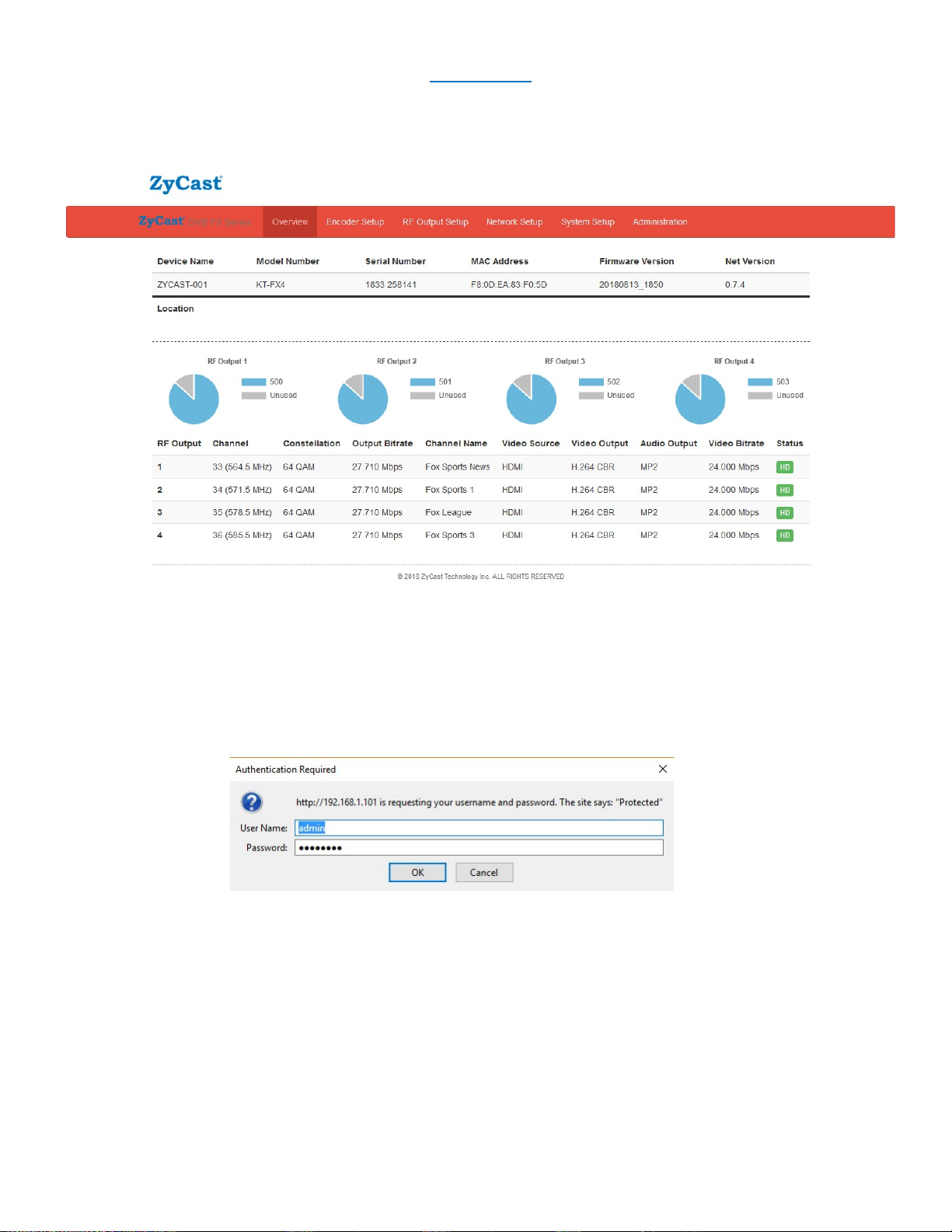
Welcome page will be displayed as shown (as below)
Note – If source is active, status will show SD or HD. If “Freerun” shows the source is not active
User will be presented with encoders 'Authentication Required' screen.
Enter User Name and Password into this section to access the settings.
User Name: admin
Password: Admin123
9 KT-FX4 Manual V1.0
Page 10
Encoder Setup
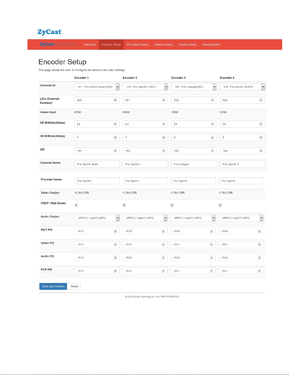
HD Bitrate setting range: 12~24 Mbps (default is 24Mbps)
SD Bitrate setting range: 1~9 Mbps (default is 5 Mbps)
* Whenever there is a PID conflict, it will pop up an Error icon to show the PID has been
occupied!
10 KT-FX4 Manual V1.0
Page 11
Encoder Setup (cont)
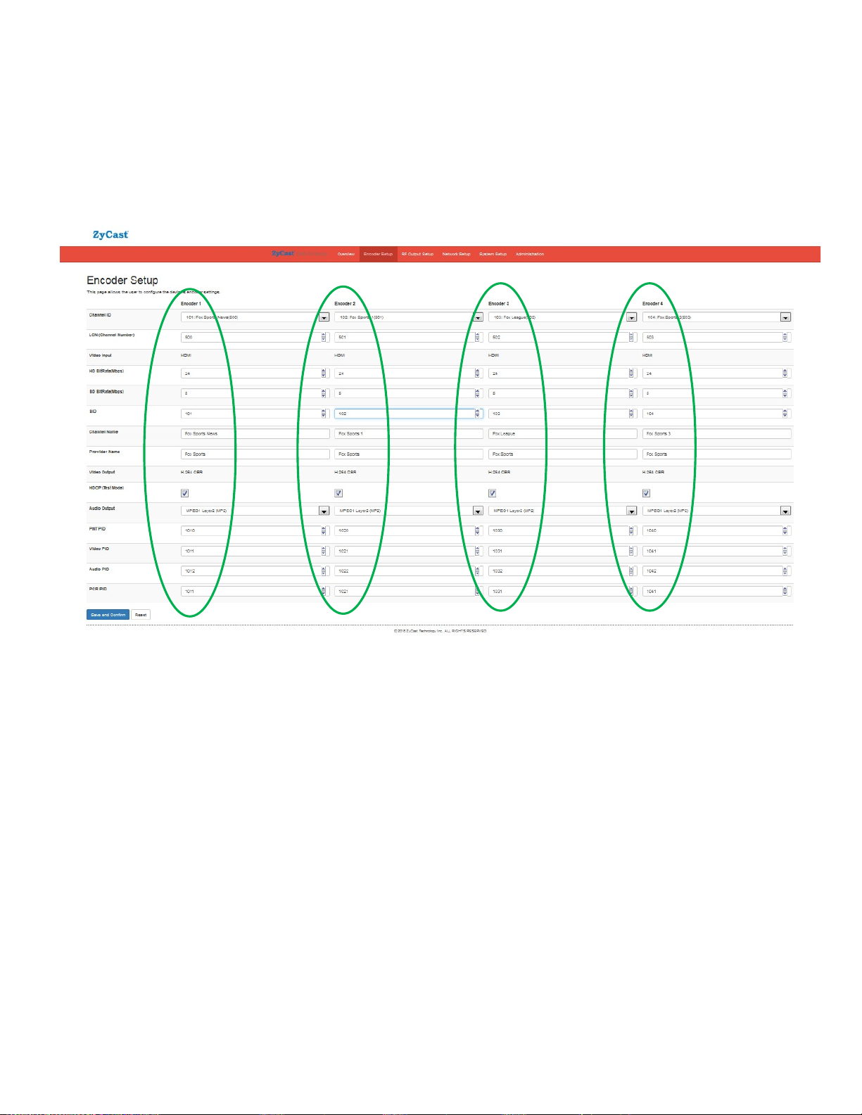
Note: Select different Channel ID (Channel Number) per input, the related parameters will automatically
change to the default Channel setting parameters, like Service ID, LCN, Channel Name, PMT PID, Video PID,
Audio PIS, PCR PID, etc. This is stop channels “clashing”
* Please refer to Foxtel Approval Channel list at the end of this manual.
11 KT-FX4 Manual V1.0
Page 12
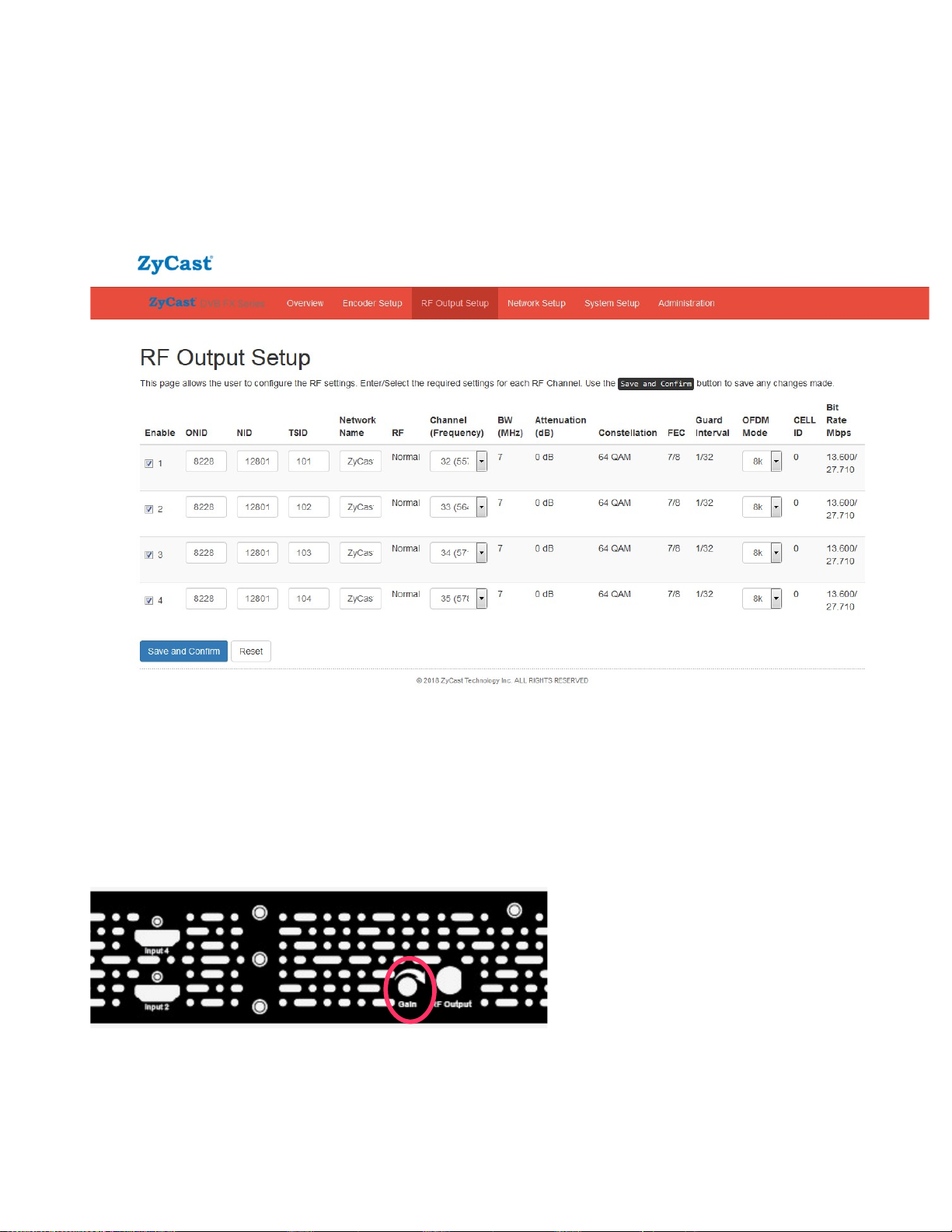
RF Output Setup
RF Output Setup page allows you to change settings to your installation requirements. These settings include
RF Output Channel, Network Name, ONID, TSID, NID and enable/disable the source.
Note – TSID will change automatically when you select the Channel ID (along with other clashing settings)
Attenuation Control
Please adjust the attenuation by adjusting the Gain control from the unit to balance your system
Note: Clockwise to increase, anti-clockwise to decrease.
12 KT-FX4 Manual V1.0
Page 13
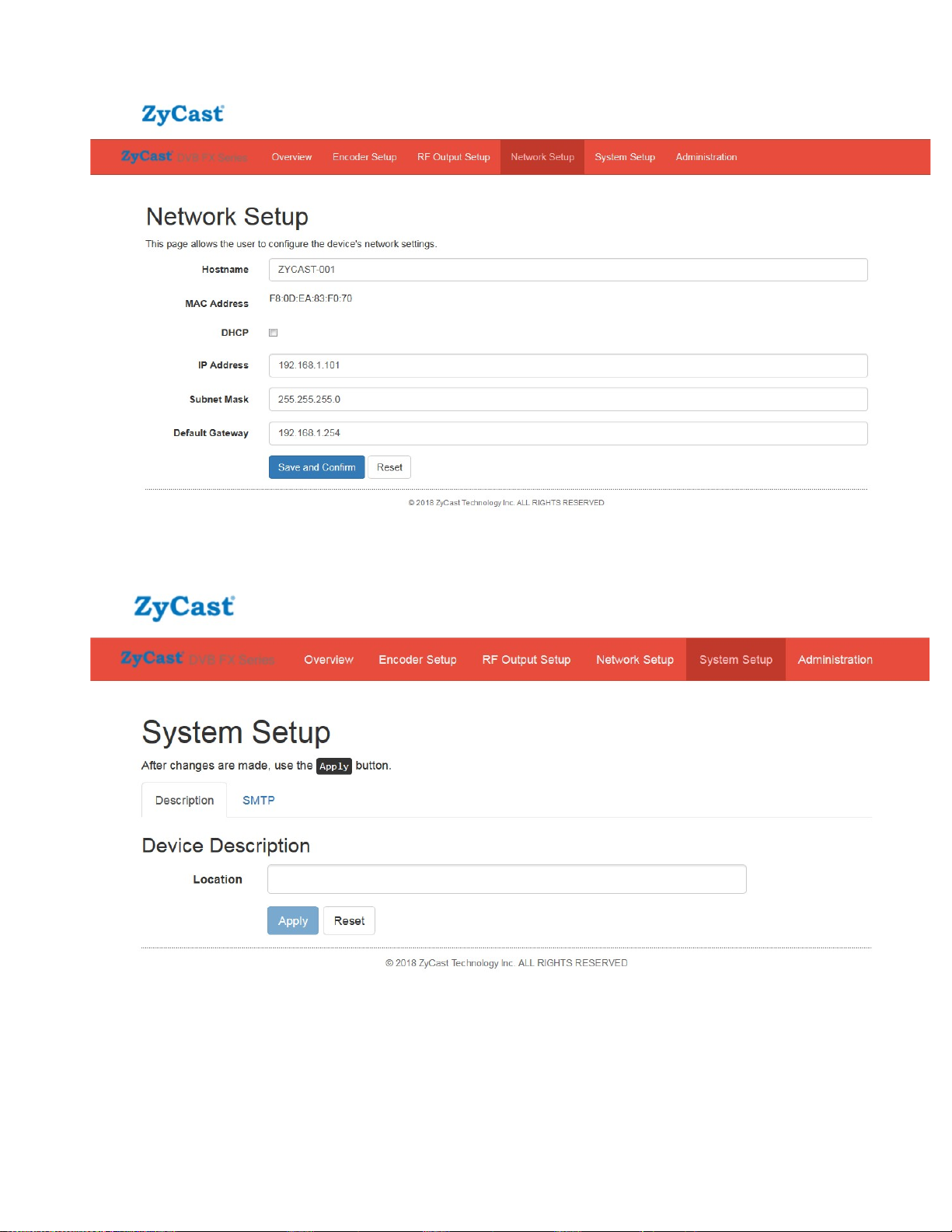
Network Setup
System Setup
13 KT-FX4 Manual V1.0
Page 14

Note: Enable SMTP to send the alert message to related persons, please set the under parameters,
then Local Save, Upload and Reboot to enable the function.
Mail feature/settings:
1. Add the new feature "SMTP" to send mail by SMTP client.
(1) At "Web Management" page, the following fields are added.
(a) Enable SMTP checkbox: the default value is "disabled",
(b) Modulator Location: 16 characters to note the modulator's location in mail,
(c) SMTP Server IP: IP address of SMTP server,
(d) Port Number: Port number of SMTP server,
(e) Mail to: mail addresses of receivers (up to 3 mail addresses).
(2) mail format goes as follows.
(a) From: KONNECT-001 (Host Name)
(b) To: (the same as "Mail to")
(c) Subject: different subjects according to different conditions go as follows.
B0001 - System is ready.
It would be sent only once after the system boots up.
E0002 Power Supply Loss: Main!
It would be sent once if the main power is off.
E0003 - Power Supply Loss: Standby!
It would be sent once if the standby power is off.
I0004 - Encoder Status Changed.
It would be sent if any encoder bitrate changed.
I0005 - System will be rebooted.
It would be sent before the system will be rebooted.
I0006 - Settings are modified by web pages.
It would be sent if the settings are modified by the web page.
I0007 - Settings are modified by LCD menu.
It would be sent if the settings are modified by LCD menu and when Info Pages are displayed.
14 KT-FX4 Manual V1.0
Page 15
Content: The content format is as following example for reference.
KONNECT-001_ (serial number of modulator)
Location: Test
IP Address: 192.168. 1.101
Host Name: KT-FX4
32 (557.5 MHz): Fox Sports News HD 24.000Mbps
33 (564.5 MHz): Fox Sports HD 24.000Mbps
34 (571.5 MHz): Fox Sports 2 HD 24.000Mbps
35 (578.5 MHz): Fox Sports 3 HD 24.000Mbps
Main Power: OK
Standby Power: OK
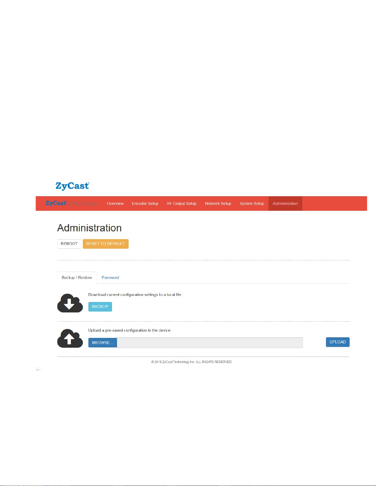
Administration
Administration is where you can change the password, back up or download configurations, default the
modulator back to factory settings upload a config file (firmware).
15 KT-FX4 Manual V1.0
Page 16
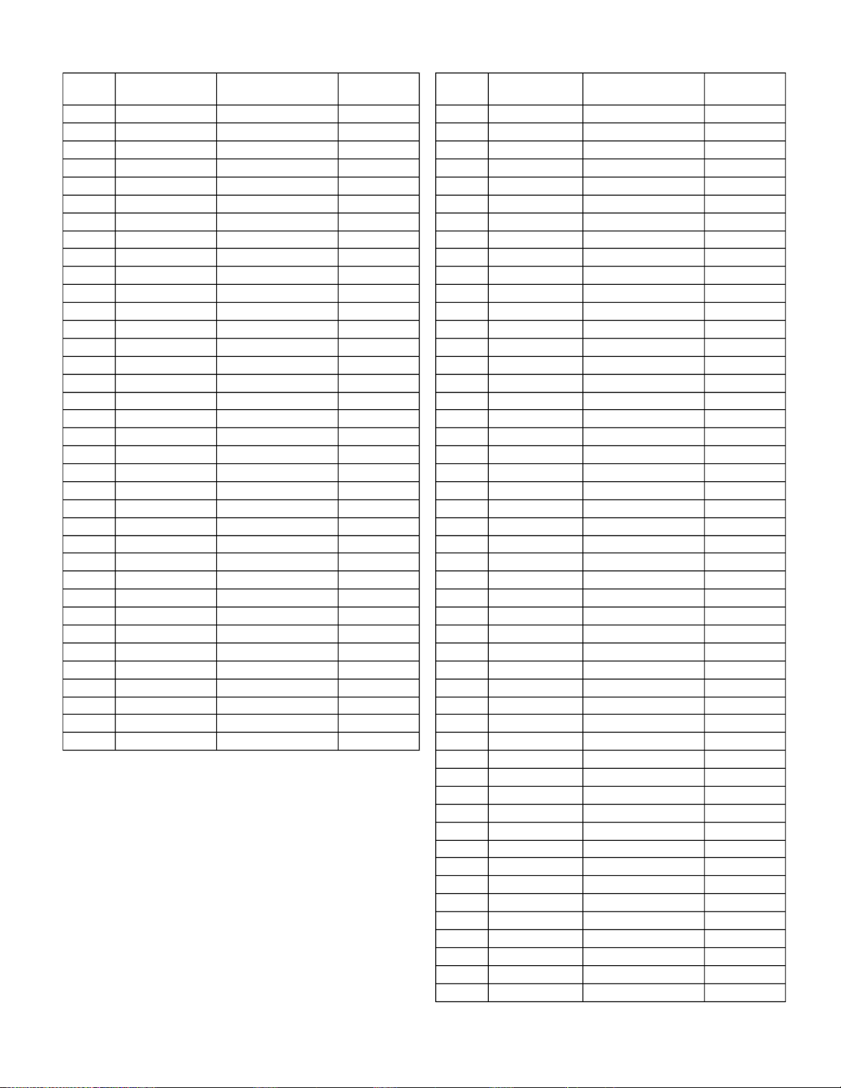
Preprogrammed Foxtel Approved Channels Spare Channels
Channel
ID #
101 Fox Sports News 500 192.168.1.101 137 Spare Channel 1 401 192.168.1.137
102 Fox Sports 1 501 192.168.1.102 138 Spare Channel 2 402 192.168.1.138
103 Fox League 502 192.168.1.103 139 Spare Channel 3 403 192.168.1.139
104 Fox Sports 3 503 192.168.1.104 140 Spare Channel 4 404 192.168.1.140
105 Fox Footy 504 192.168.1.105 141 Spare Channel 5 405 192.168.1.141
106 Fox Sports 5 505 192.168.1.106 142 Spare Channel 6 406 192.168.1.142
107 Fox Sports 6 506 192.168.1.107 143 Spare Channel 7 407 192.168.1.143
108 Fox Sports M ore 507 192.168.1.108 144 Spare Channel 8 408 192.168.1.144
109 ESPN 508 192.168.1.109 145 Spare Channel 9 409 192.168.1.145
110 ESPN 2 509 192.168.1.110 146 Spare Channel 10 410 192.168.1.146
111 Bein Sports 1 513 192.168.1.111 147 Spare Channel 11 411 192.168.1.147
112 Bein Sports 2 514 192.168.1.112 148 Spare Channel 12 412 192.168.1.148
113 Bein Sports 3 515 192.168.1.113 149 Spare Channel 13 413 192.168.1.149
114 Eurosport 511 192.168.1.114 150 Spare Channel 14 414 192.168.1.150
115 Chelsea TV 516 192.168.1.115 151 Spare Channel 15 415 192.168.1.151
116 LFCTV 517 192.168.1.116 152 Spare Channel 16 416 192.168.1.152
117 MUTV 518 192.168.1.117 153 Spare Channel 17 417 192.168.1.153
118 Sky Racing 1 526 192.168.1.118 154 Spare Channel 18 418 192.168.1.154
119 Sky Racing 2 527 192.168.1.119 155 Spare Channel 19 419 192.168.1.155
120 SkyThoroughredCe 528 192.168.1.120 156 Spare Channel 20 420 192.168.1.156
121 Racing.com 529 192.168.1.121 157 Spare Channel 21 421 192.168.1.157
122 Sky News 601 192.168.1.122 158 Spare Channel 22 422 192.168.1.158
123 Sky News Business 602 192.168.1.123 159 Spare Channel 23 423 192.168.1.159
124 Sky News Weather 603 192.168.1.124 160 Spare Channel 24 424 192.168.1.160
125 Fox News 604 192.168.1.125 161 Spare Channel 25 425 192.168.1.161
126 CNN 605 192.168.1.126 162 Spare Channel 26 426 192.168.1.162
127 CNBC 644 192.168.1.127 163 Spare Channel 27 427 192.168.1.163
128 APAC 648 192.168.1.128 164 Spare Channel 28 428 192.168.1.164
129 BBC World News 649 192.168.1.129 165 Spare Channel 29 429 192.168.1.165
130 Bloomberg 650 192.168.1.130 166 Spare Channel 30 430 192.168.1.166
131 Al Jazeera 651 192.168.1.131 167 Spare Channel 31 431 192.168.1.167
132 V 801 192.168.1.132 168 Spare Channel 32 432 192.168.1.168
133 MTV Music 803 192.168.1.133 169 Spare Channel 33 433 192.168.1.169
134 MTV Dance 804 192.168.1.134 170 Spare Channel 34 434 192.168.1.170
135 Max 805 192.168.1.135 171 Spare Channel 35 435 192.168.1.171
136 CMC 815 192.168.1.136 172 Spare Channel 36 436 192.168.1.172
Channel
Name
LCN
(Channel Number)
IP Address IP Address
Chan nel
ID #
173 Spare Channel 37 437 192.168.1.173
174 Spare Channel 38 438 192.168.1.174
175 Spare Channel 39 439 192.168.1.175
176 Spare Channel 40 440 192.168.1.176
177 Spare Channel 41 441 192.168.1.177
178 Spare Channel 42 442 192.168.1.178
179 Spare Channel 43 443 192.168.1.179
180 Spare Channel 44 444 192.168.1.180
181 Spare Channel 45 445 192.168.1.181
182 Spare Channel 46 446 192.168.1.182
183 Spare Channel 47 447 192.168.1.183
184 Spare Channel 48 448 192.168.1.184
185 Spare Channel 49 449 192.168.1.185
186 Spare Channel 50 450 192.168.1.186
Channel
Name
LCN
(Channel Number)
16 KT-FX4 Manual V1.0
Page 17
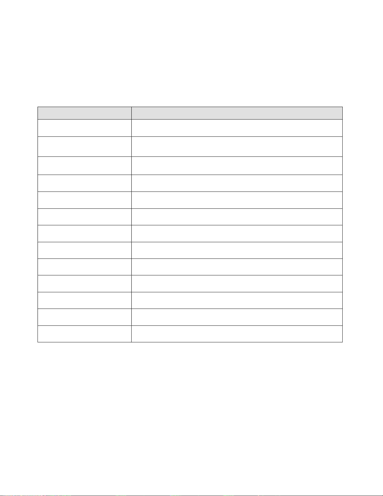
PRODUCT NOTES:
ITEM VALUE
DEVICE NAME
PURCHASE DATE
INSTALLATION DATE
SERIAL NUMBER
FIRMWARE VERSION
KT-FX4 HD Encoder/Modulator Notes
Video Input 1
Video Input 2
Video Input 3
Video Input 4
17 KT-FX4 Manual V1.0
 Loading...