

Page 1

digi-MOD HD-4797
www.digi-modbyzycast.com
HD-4797 4-Input HD Digital Modulator
with HDMI Loop Through and IR
User Guide and Install Manual
TABLE OF CONTENTS
SAFETY PRECAUTIONS.....................................................................................................2
PACKAGE CONTENTS.......................................................................................................2
PRODUCT DESCRIPTION...................................................................................................3
Features............................................................................................................................3
SPECIFICATIONS...............................................................................................................4
INSTALLATION..................................................................................................................5
UNPACKING and INSPECTION..........................................................................................................................................................................5
HARDWARE INSTALLATION and CONNECTIONS....................................................................................................................................5
Reset to Default.......................................................................................................................................................................................................6
......................................................................................................................................................................................................................................6
MODULATOR SETUP AND CONFIGURATION.....................................................................7
DEVICE Programming and Setup.....................................................................................................................................................................7
Connecting to the GUI Interface:........................................................................................7
Front Panel LCD Encoder Menu Map...........................................................................................................................................................13
Modulator Configuration via Front Panel LCD..................................................................14
Common Setup Menu..................................................................................................................................................................................................15
RF Setup Menu ..............................................................................................................................................................................................................15
Encoder Setup Menu ..................................................................................................................................................................................................16
Network Setup...............................................................................................................................................................................................................17
HD-4797 HD Encoder/Modulator Notes..........................................................................18
1 HD-4797 Manual V1.0
Page 2

SAFETY PRECAUTIONS
The presence of this symbol is to alert the installer and user to the presence of
uninsulated dangerous voltages within the product’s enclosure that may be of sufficient
magnitude to produce a risk of electric shock.
TO REDUCE THE RISK OF FIRE OR ELECTRIC SHOCK, DO NOT EXPOSE THIS DEVICE
TO RAIN OR MOISTURE. DO NOT OPEN THE UNIT. REFER SERVICING TO QUALIFIED
PERSONNEL ONLY.
DO NOT apply power to the unit until all connections have been made, all components have been installed
and all wiring has been properly terminated.
DO NOT terminate, change or uninstall any wiring without first disconnecting the unit’s power adapter from
the device.
This device is supplied with the appropriately rated 12VDC power supply with the center pin positive. The
use of any other power supply could cause damage and invalidate the manufacturer’s warranty.
DO NOT power on the unit until all cables and connections to the device have been properly connected.
The device should be installed in an environment consistent with its operating temperature specifications.
Placement next to heating devices and ducts is to be avoided as doing so may cause damage. The device
should not be placed in areas of high humidity.
DO NOT cover any of the device’s ventilation openings.
If the device has been in a cold environment allow it to warm to room temperature for at least 2 hours
before connecting power
.
PACKAGE CONTENTS
This package contains:
One HD-4797 HD Digital Modulator
One Power Cord
One User Guide and Install Manual
Inspect the package before starting installation to ensure there is no damage and all supplied contents are
present. Contact your distributor or dealer should the device be damaged or package contents are incomplete.
2 HD-4797 Manual V1.0
Page 3
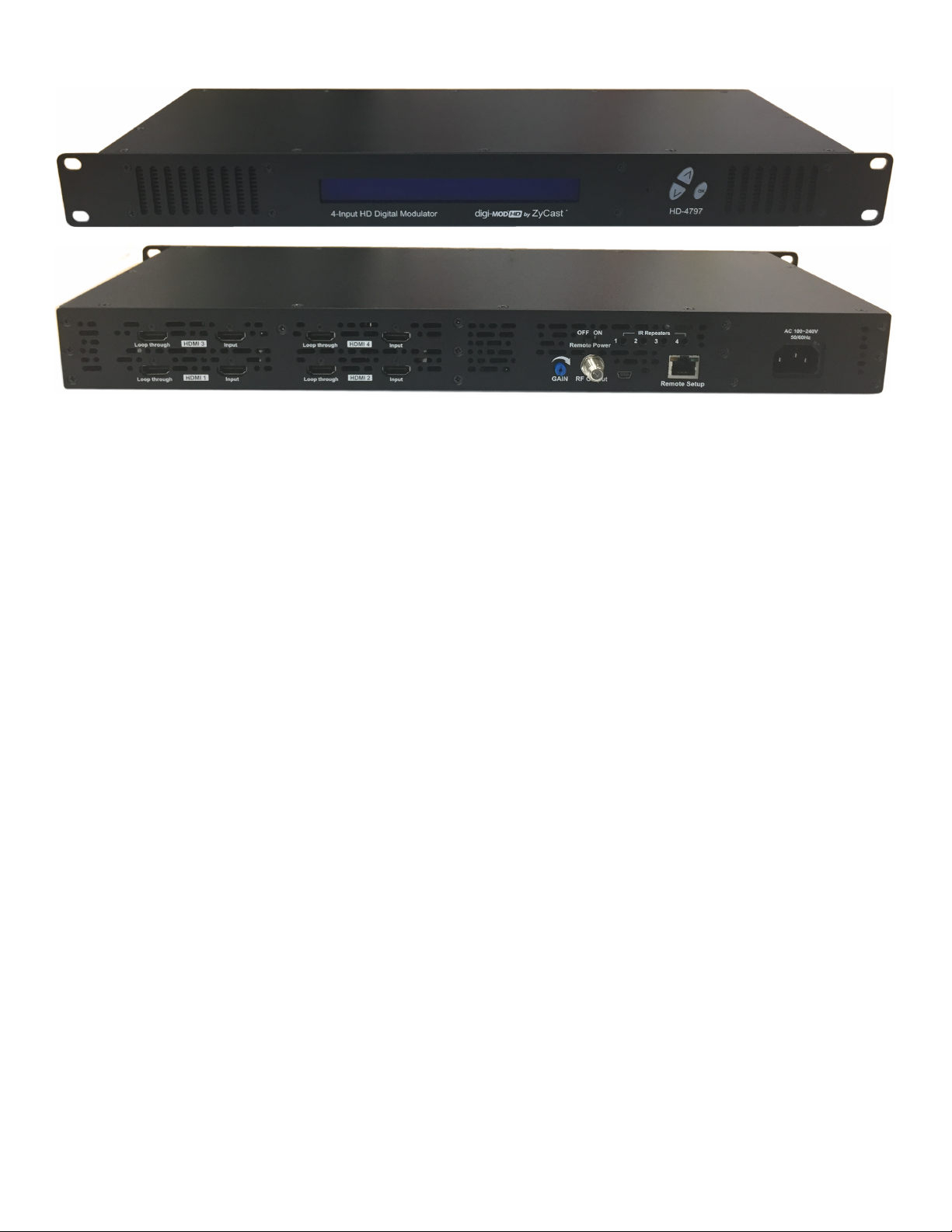
PRODUCT DESCRIPTION
digi-MOD HD by ZyCast HD-4797 Modulator converts Digital Video Broadcasting (DVB) high
definition video and audio signals to COFDM. The HD Digital Modulator is with HDMI Loop Through ,
IR function, and manual Gain adjustment. The unit's front-mounted LCD display allows for easy
configuration and adjustments.
ZyCast's HD-4797 Digital Modulator is ideal for any Commercial RF Network. The high quality HD
design allows for watching action packed movies and sports channels on any HDTV. The space
saving design delivers up to 4 High Quality HD channels in a single 1RU space.
Features
☼ H.264 AVC
☼ HDMI Input, HDMI Loop through, RF Output
☼ Built-in IR control
☼ Gain Control (20dB Manual Attenuation)
☼ RJ-45 port for Web Management
☼ Video resolution : Up to 1080p
☼ Perfect, clean, and clear picture on high motion video, sports, text crawls/rolls, etc.
☼ Front panel LCD Display for easy installation
☼ Cool & silent operation
☼ Rack mountable 1RU height
3 HD-4797 Manual V1.0
Page 4
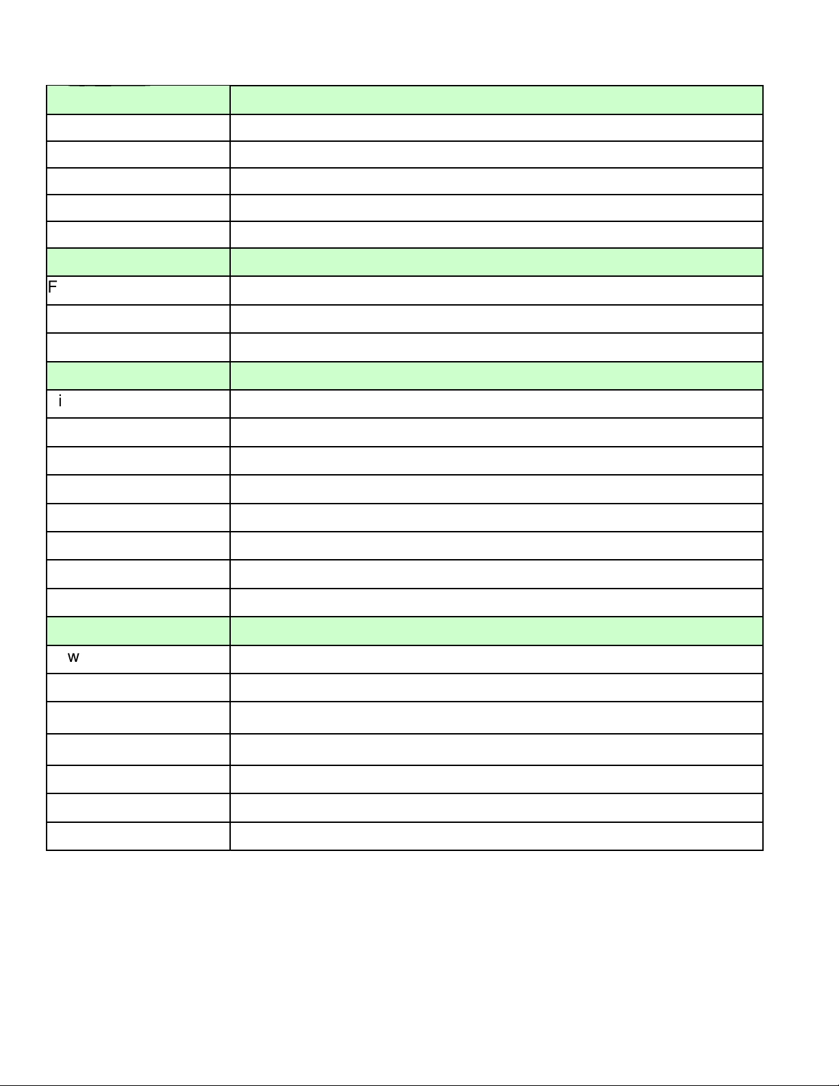
SPECIFICATIONS
INPUT HD-4797
Video Input HDMI
Video Input Level 0.7 – 1.4V(peak-to peak)
Video Mode PAL / NTSC
Audio input Stereo
Audio Input Level 0.4 – 4.8V (p-to-p)
OUTPUT
Frequency Range Local country available
Output Level 85 dBµV
MER 36 dB typ.
MODULATION
Video Resolution 480i, 480p, 576i, 576p, 720p, 1080i, 1080p
Video Compression H.264 AVC
Audio Compression MPEG1 Layer II / AAC
LCN Yes
Carrier (OFDM Mode) 2K/8K
Guard Intervals 1/32
Code Rate (FEC) 7/8
Constellations 64-QAM
GENERAL
Power Supply 12 VDC 4 Amp.
Consumption 1650 mA
Operating Temperature
Storage Temperature
0oC to +45oC
-10oC to +60oC
Languages English
Dimensions 482.7mm x 187mm x 44.4mm
Weight 2.76 kgs
*Specifications subject to change without prior notice
4 HD-4797 Manual V1.0
Page 5
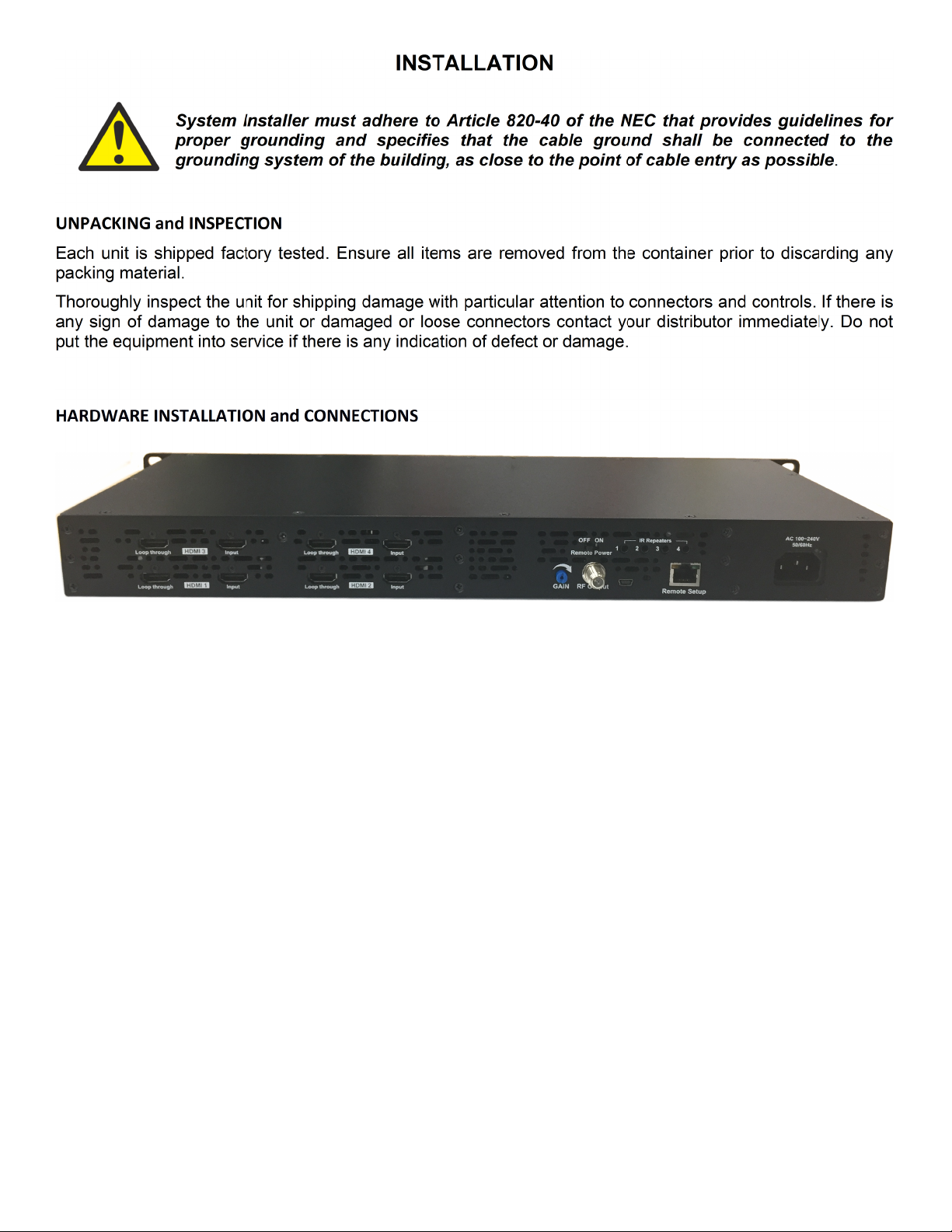
1. Use HDMI cables to connect the video sources (e.g., CATV, DVD, VCR, Camera) to the unit’s HDMI Input
port 1,2,3,4. It is highly recommended that quality HDMI cables be used for all video source connections.
2. Use HDMI cables to connect the unit’s HDMI Loop through port 1,2,3,4 to televisions. Or Use a quality
75Ω coaxial cable with “F” connectors from the unit’s RF Output jack to the distribution system
(combiner or reverse splitter) or directly to a television.
3. Use a quality RJ45 cable to connect the Remote Setup port to a computer RJ45 port for setup/manage
the unit.
4. If applicable, connect an IR repeaters jack to the IR ports for IR remote control fuction. If needed, you
can turn ON the REMOTE POWER for sending a 12V power through RF Output to the connected module.
5. Connect the included power cord to the unit’s DC 12V POWER jack.
6. Connect the power supply to an appropriately rated AC power outlet.
5 HD-4797 Manual V1.0
Page 6
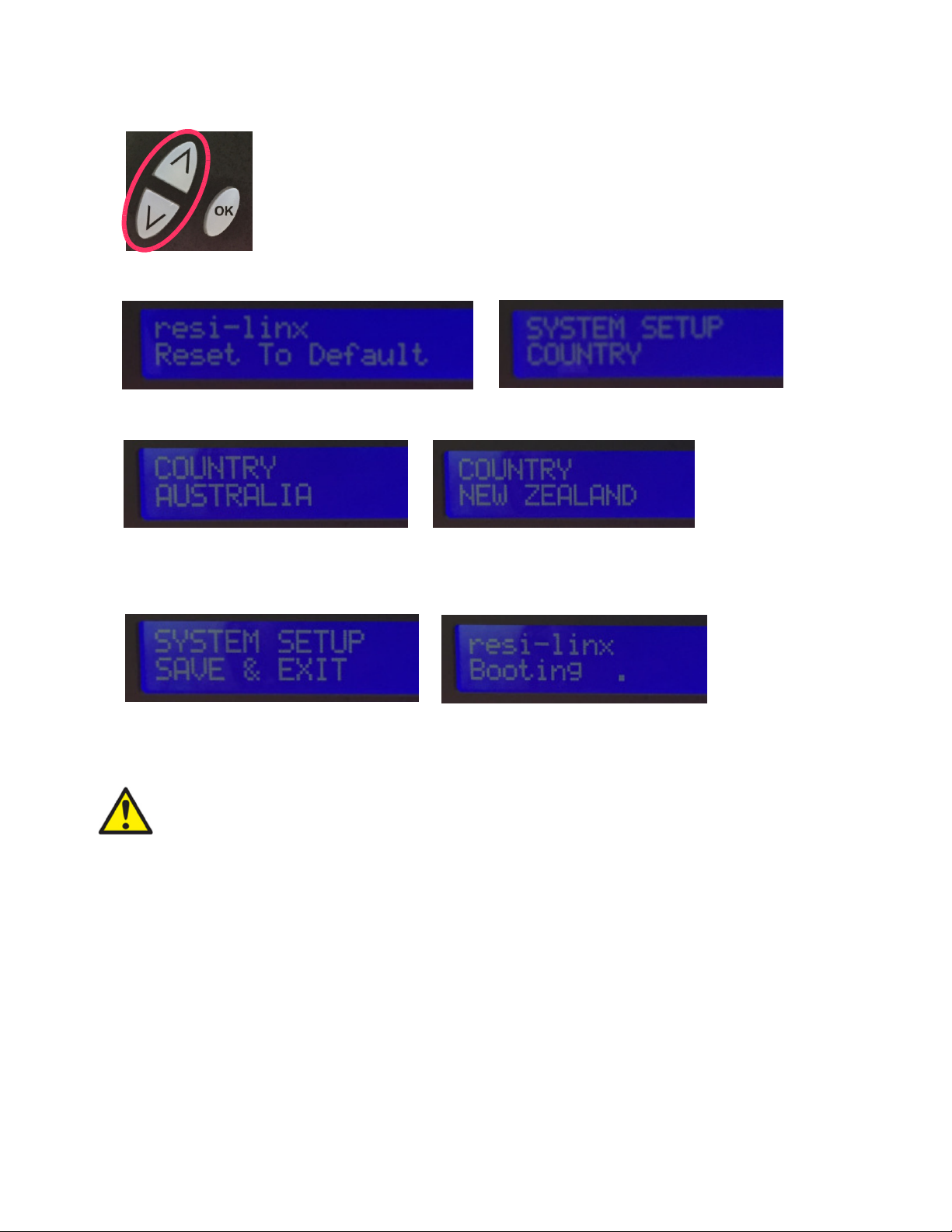
Reset to Default
1. Turn OFF the unit. While pressing UP and DOWN buttons at the same time, power ON the unit.
2. Release the UP and DOWN buttons when the LCD shows Reset To Default.
3. Press OK button to select Country : Australia or New Zealand
4. Press OK button again when the country selected, then press UP or DOWN button to show
SAVE & EXIT.
5. Press OK button to Save and Exit. The unit will Booting on.
Caution: Once this process is complete the unit will automatically reset to the factory
default settings. All settings or changes to the encoder/modulator will be lost.
6 HD-4797 Manual V1.0
Page 7
MODULATOR SETUP AND CONFIGURATION
DEVICE Programming and Setup
To setup and program the Encoder you can use the GUI interface or the LCD Front Panel
Note: The installer can set to enable DHCP via Front Panel LCD at the WEB
MANAGEMENT SETUP setion.
Connecting to the GUI Interface:
Factory Default IP: 192.168.1.9
1. Connect an Ethernet cable directly (no Cross Over cable required) to the Web Management Port
on the rear panel of the encoder or connect the Ethernet cable to an Ethernet switch. Connect an
Ethernet Cable to your PC/Laptop.
2. Modify your PC/Laptop IP address to 192.168.1.11.
3. Enter ‘192.168.1.9’ into your web browser.
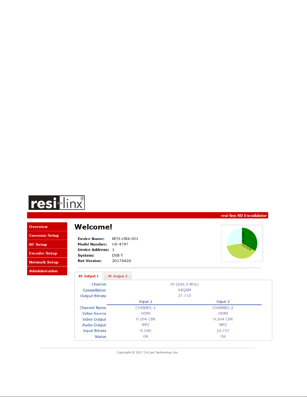
4. The Welcome Page will shown.
Welcome page will be displayed as shown
7 HD-4797 Manual V1.0
Page 8
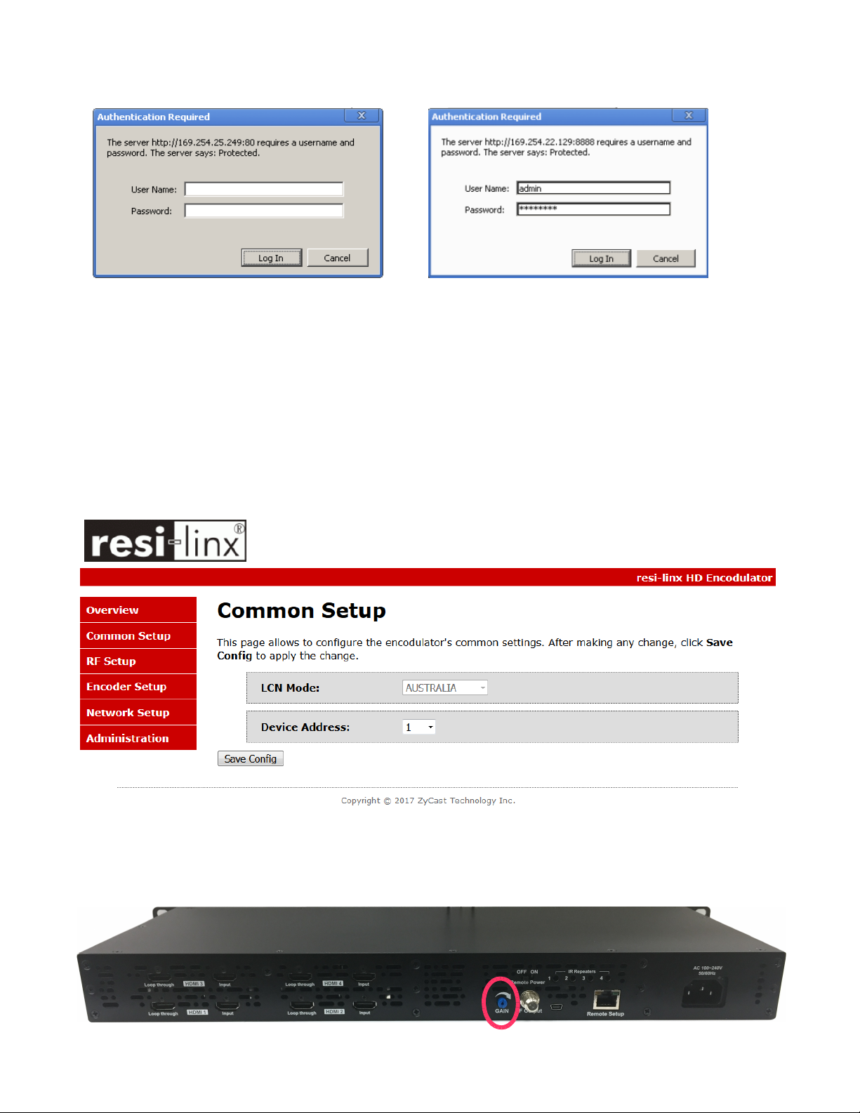
Select the Common Setup tab.
User will be presented with encoders 'Authentication Required' screen.
Enter User Name and Password.
User Name: admin
Password: Admin123
Common Setup
Remark: The Attenuation in the Common Setup is reserved. Please adjust the attenuation by
adjusting the Gain control from the unit.
8 HD-4797 Manual V1.0
Page 9
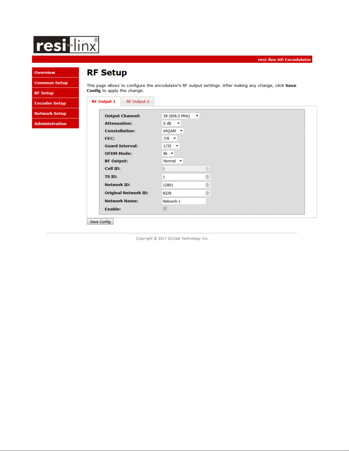
RF Setup
9 HD-4797 Manual V1.0
Page 10
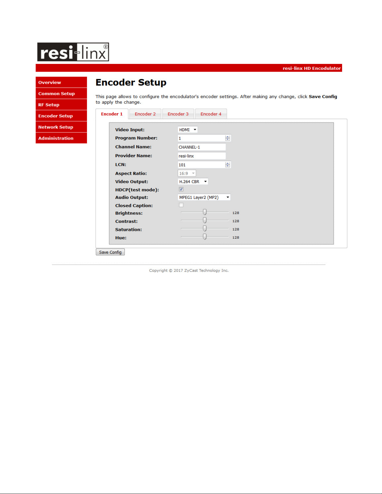
Encoder Setup
10 HD-4797 Manual V1.0
Page 11
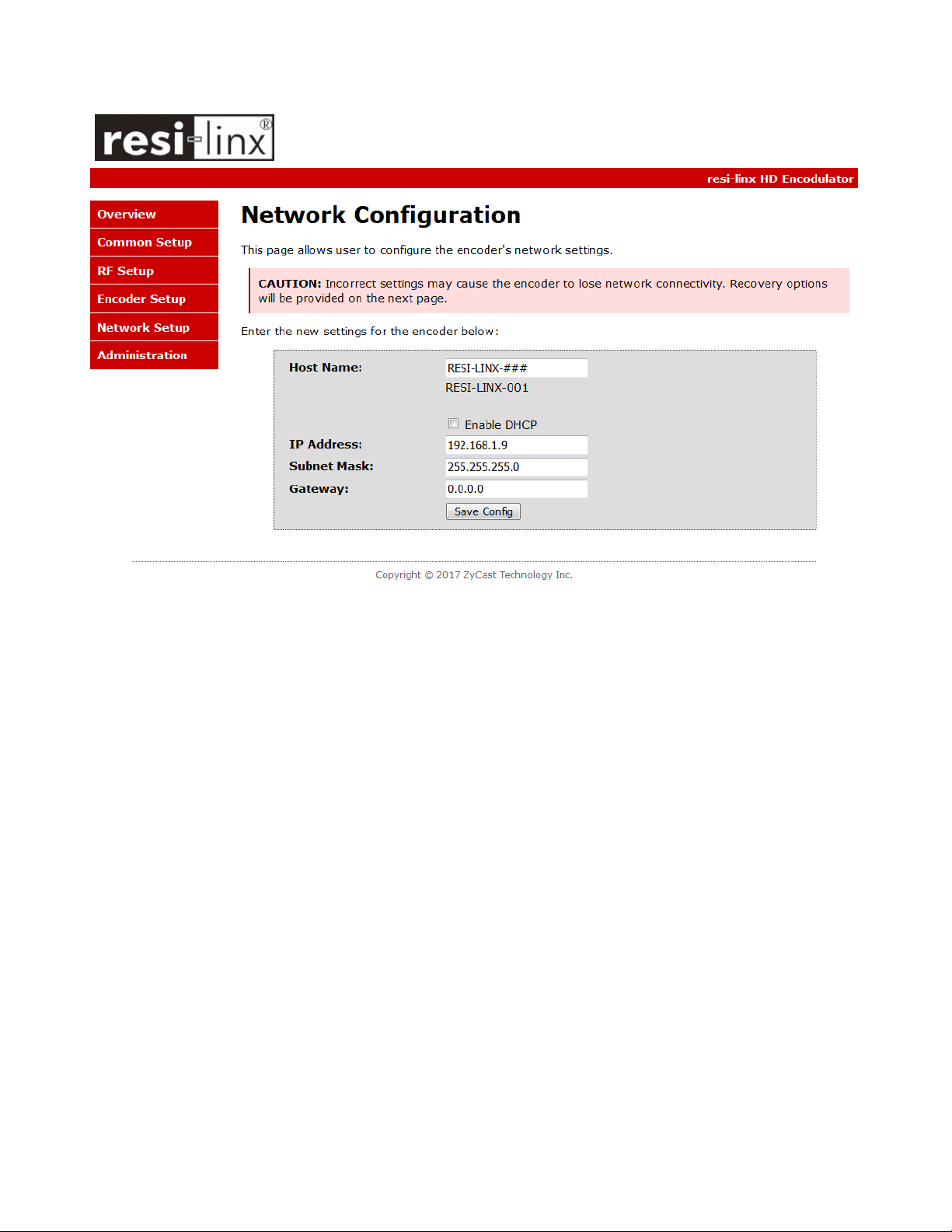
Network Setup
11 HD-4797 Manual V1.0
Page 12
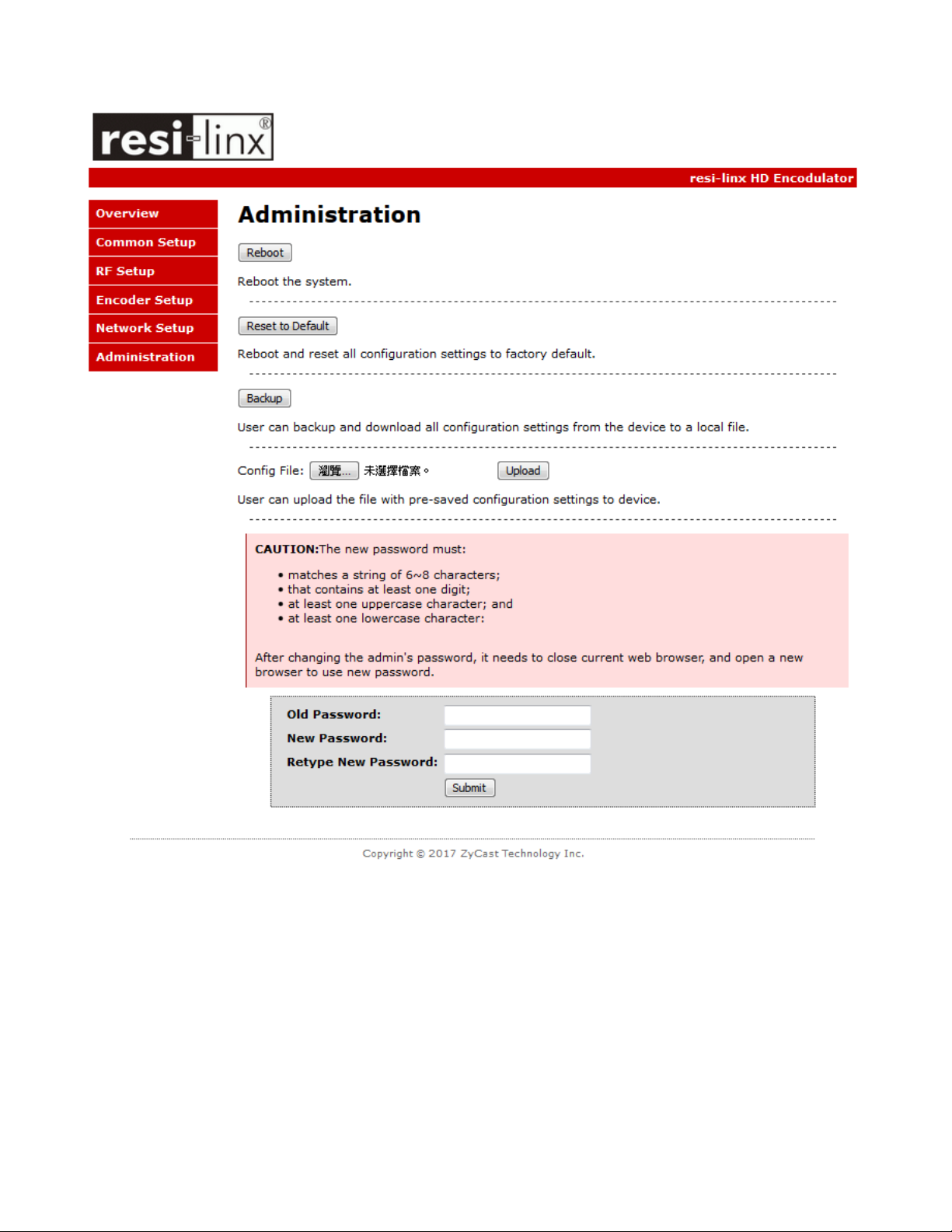
Administration
12 HD-4797 Manual V1.0
Page 13

Front Panel LCD Encoder Menu Map
Main Menu
Common
Setup
Device
Address
Default
Config
Back to
Main
RF Setup
Select RF
Enable RF
Output
Channel
Attenuation
FEC
Guard
Interval
OFDM Mode
TS ID
Network ID
ORG
Network ID
Network
Name
Back to
Main
Encoder
Setup
Select
Encoder
Video Input
Program
Num
Channel
Name
Provider
Name
LCN
HDCP
Audio
output
Back to
Main
Network
Setup
DHCP
IP Address
Subnet
mask
Gateway
Back to
Main
13 HD-4797 Manual V1.0
Page 14

Modulator Configuration via Front Panel LCD
Once the encoder is powered up it will go through its initial booting process. Once the unit has completed
its initial “Booting” up process the LCD will display IN-1..., Bit Rate information, Channel-1...., and other
information in the LCD Display Window. When visible the unit is ready for programming or operation.
The LCD will display data as it cycles through the available information.
Screen Views:
1: Inputs, Mbps, Channel Names, Video Output Type, Audio Output type
IN-1 10.127Mbps CHANNEL-1 H.264 MP2
IN-2 10.741Mbps CHANNEL-2 H.264 MP2
Note: The device is a QUAD version and the below screen will display all input data as is cycles through
the data available.
2: Use the Scroll Up/Down button to display RF-1 / RF-2 data, Physical Output Channel, Constellation,
FEC setting, OFDM Mode Selection.
39 (606.5 MHz) QAM 64 7/8 1/32 8K
40 (613.5 MHz) QAM 64 7/8 1/32 8K
3: Use the Scroll Up/Down button to display IP address
NETWORK FIXED IP 192.168. 1. 9
SM 255.255.255. 0 GW 0. 0. 0. 0
Main Menu– To access the Main Menu first enter the password by pressing the OK button. Use the Scroll
Up/Down buttons to enter the password. Once the password is entered press the OK button again and
the LCD Screen will display “Main Menu Common Setup”.
Password – Use the Scroll Up/Down buttons to enter the password. Password is 0000. Press the OK
button for each number to enter the password. Press OK again after the display shows …... HD Series.
PASSWORD=?
0
14 HD-4797 Manual V1.0
Page 15

Common Setup Menu
♣
Device Address – Use the Scroll Up/Down button to select Device Address. Press the OK
button to enter the Device Address menu. Use the Scroll Up/Down to select the Desired
Address ranging from 1 to 255 then press OK to set. A unique device address is required if
setting up more than 1 encoder per site. This allows the user to distinguish each device.
♣
Default Configuration –To reset the Encoder/Modulator back to the factory default select
the Default Configuration Menu. Press OK to enter the Default Configuration Menu. There
are three options that you can choose. Using the Up/Down button select No, New Zealand
and Australia. Press OK to reset all programmed settings back to the factory default setting.
♣
Back to Main- Select Back to Main to escape the Common Setup Menu.
RF Setup Menu
♣
Select RF- Press the OK button to enter the Select RF menu. Use the Scroll Up/Down button
to Select the RF section of the Encoder. Select 1 or Select 2.
Note: The QUAD version of the unit has 2 RF Sections. The Quad will place 2 RF channels in
the first RF output and 2 RF Channels in the second RF output.
♣
Enable RF- Use the Scroll Up/Down button to select Enable/Disable RF.
♣
Output Channel – Use the Scroll Up/Down button to change the output channel. Use the
Scroll Up/Down buttons to select the desired Output Channel. Once the desired output
channel is selected press the OK button to set the channel.
The LCD Display will show both the channel number and the frequency number of the
output channel (example: 39 (606.5 MHz))
♣
Attenuation – Use the Scroll Up/Down button to select Attenuation. Press the OK button to
enter the Attenuation menu. Use the Scroll/Up down button to select the desired
attenuation in 1dB increments from 0 to -20 dB. Once the desired attenuation level is found
press the OK button to set.
♣
FEC- The FEC is default 7/8.
♣
GUARD INTERVAL – The GUARD INTERVAL is default 1/32.
♣
OFDM - Use the Scroll Up/Down button to select the OFDM menu. Press the OK button to
enter the OFDM menu. Use the Scroll Up/Down to select the OFDM 2K or 8K. Press OK to
set.
♣
TS ID – Use the Scroll Up/Down button to select TS ID. Press the OK button to enter the TS
ID menu. Use the Scroll Up/Down button to select the desired Stream ID ranging from 1 to
65535 then press the OK button to set.
♣
Network ID – Use the Scroll Up/Down button to select Network ID. Press the OK button to
enter the Network ID menu. Use the Scroll Up/Down button to select the desired Network
ID ranging from 1 to 65535 then press the OK button to set.
♣
ORG Network ID – Use the Scroll Up/Down button to select ORG Network ID. Press the OK
button to enter the ORG Network ID menu. Use the Scroll Up/Down button to select the
desired ID ranging from 1 to 65535 then press the OK button to set.
♣
Network Name – Use the Scroll Up/Down button to select Network Name. Press the OK
button to enter the Network Name menu. Use the Scroll Up/Down button to select the first
character for the desired Network Name then press the OK button to set. Repeat the
15 HD-4797 Manual V1.0
Page 16

process for each character in the desired Network Name. A Network Name can consist up
1
to 16 characters.
♣
Back to Main- Select Back to Main to escape the RF Setup Menu.
Encoder Setup Menu
♣
Select Encoder- Use the OK button to enter the Select Encoder Menu. Using the Scroll
Up/Down buttons select the encoder you wish to program. Use the OK button to set the
Encoder. Select Encoder 1, 2, 3, or 4 based on your model number.
Once Selected the Display will indicate which Encoder you are programming while in the
setup function
SELECT ENCODER 1
♣
Video Input – The Video Input is default HDMI.
♣
Program Num - Use the Scroll Up/Down button to set 1 Program Num(Number). Press the
OK button to enter the Program Num menu. Use the Scroll Up/Down to select Program
Num ranging from 1 to 65534 then press OK to set.
♣
Channel Name – Use the Scroll Up/Down button to select Channel Name. Press the OK
button to enter the Channel Name menu. Use the Scroll Up/Down menu to select the first
character of the desired Channel Name then press the OK button to set. Repeat the process
until the Channel Name is completed.
The Channel Name can be 7 characters long. Factory Default: CHANNEL-1.
♣
PROVIDER NAME – Use the Scroll Up/Down button to select Provider Name. Press the OK
button to enter the Provider Name menu. Use the Scroll Up/Down menu to select the first
character of the desired Provider Name then press the OK button to set. Repeat the process
until the Provider Name is completed. The Provider Name can be 16 characters long.
♣
LCN-Use the Scroll Up/Down button to set LCN. Press the OK button to enter The Source ID
menu. Use the Scroll Up/Down to set the Source ID. Range: 1 to 999. Press OK to set.
Factory default : 101.
♣
HDCP- Use the Scroll Up/Down button to select the HDCP menu- Use the Scroll Up/Down
button to select the HDCP menu. Press the OK button to enter the HDCP menu. Select
Enable / Disable, and press OK to set.
NOTE: It is the installers / property owner / integrator's responsibility to contract with the
service provider regarding content authorization and the use of HDCP.
♣
Audio Output – Use the Scroll Up/Down button to select Audio Output. Press the OK
button to enter the Audio Output menu. Use the Scroll Up/Down button to select the Audio
Output option: MP2(MPEG1 Layer2 Audio), AAC. Factory default: MP2. Press the OK button
to set.
♣
Back to Main- Select Back to Main to escape the Encoder Setup Menu.
16 HD-4797 Manual V1.0
Page 17

Network Setup
♣
DHCP – Use the Scroll Up/Down button to select DHCP. Press the OK button to enter the
DHCP menu. Use the Scroll Up/Down button to Enable/Disable. Press the OK button to set.
♣
IP Address – Use the Scroll Up/Down button to select IP Address. Press the OK button to
enter the IP Address menu. Use the Scroll Up/Down button to enter the IP Address. Use the
Scroll Up/Down menu to select the desired IP Address then press the OK button to set.
Repeat the process until the IP Address is completed. Press the OK button to set. Note: If
DHCP is enabled you will not be able to set an IP address. Select DHCP disabled if Static IP
Address required.
♣♣♣♣
Subnet Mask – Use the Scroll Up/Down button to select Subnet Mask. Press the OK button
to enter the Subnet Mask menu. Use the Scroll Up/Down button to enter the Subnet Mask.
Use the Scroll Up/Down menu to select the first number of the desired Subnet Mask then
press the OK button to set. Repeat the process until the Subnet Mask is completed. Press
the OK button to set.
♣
Gateway – Use the Scroll Up/Down button to select Gateway Address. Press the OK button
to enter the Gateway Address menu. Use the Scroll Up/Down button to enter the Gateway
Address. Use the Scroll Up/Down menu to select the first number of the desired Gateway
Address then press the OK button to set. Repeat the process until the Gateway Address is
completed. Press the OK button to set.
♣
♣
Back to Main- Select Back to Main to escape the Web Management Network Setup
♣ ♣
Menu.
17 HD-4797 Manual V1.0
Page 18
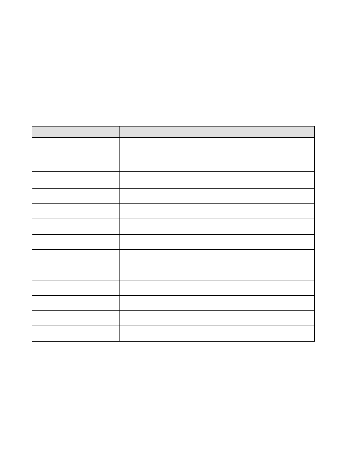
PRODUCT NOTES:
ITEM VALUE
DEVICE NAME
PURCHASE DATE
INSTALLATION DATE
SERIAL NUMBER
HD-4797 HD Encoder/Modulator Notes
FIRMWARE VERSION
Video Input 1
Video Input 2
Video Input 3
Video Input 4
Distributed by:
18 HD-4797 Manual V1.0
Page 19

www.digi-modbyzycast.com.tw
WARRANTY
digi-MOD states that the warrant that the customer can rely on is that provided by the manufacturer.
In the event of any warranty claim please contact your place of purchase and it will be forwarded it
to the manufacturer. The manufacturer will then determine the extent of their liability.
19 HD-4797 Manual V1.0
 Loading...