

Page 1
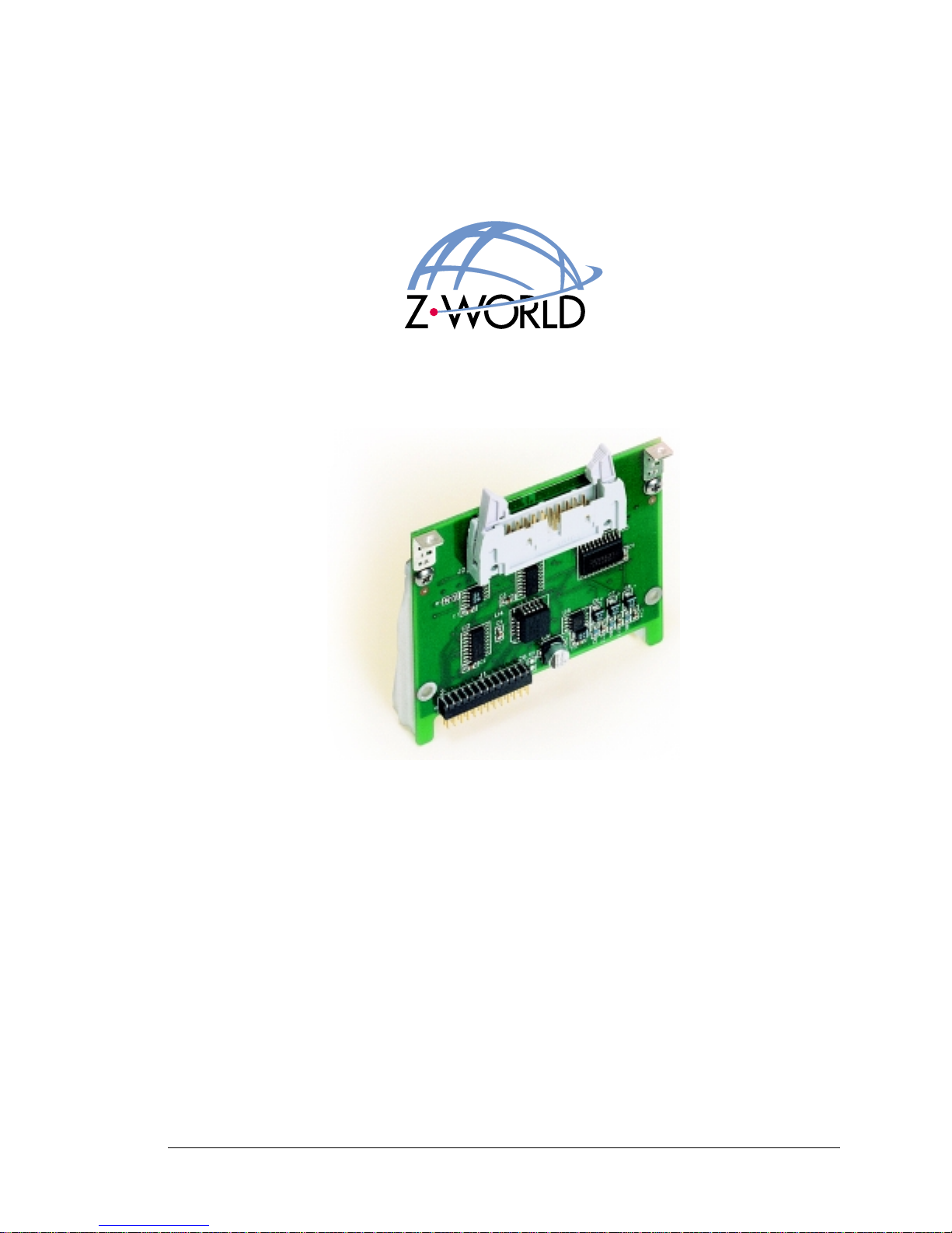
A/D Converter Cards (SR9300 Series)
Smart Star Modular C-Programmable Control System
User’s Manual
010215 - A
Page 2

Digital I/O Cards User’s Manual
Part Number 019-0086 • 010215 - A • Printed in U.S.A.
Copyright
© 2001 Z-World, Inc. • All rights reserved.
Z-World reserves the right to make changes and improvements to its products without pro-
viding notice.
Trademarks
• Dynamic C® is a registered trademark of Z-World, Inc.
• Windows® is a registered trademark of Microsoft Corporation
• Rabbit 2000™ is a trademark of Rabbit Semiconductor
Notice to Users
When a system failure may cause serious consequences, protecting life and property
against such consequences with a backup system or safety device is essential. The buyer
agrees that protection against consequences resulting from system failure is the buyer’s
responsibility.
This device is not approved for life-support or medical systems.
All Z-World products are 100 percent functionally tested. Additional testing may include
visual quality control inspections or mechanical defects analyzer inspections. Specifications are based on characterization of tested sample units rather than testing over temperature and voltage of each unit. Z-World may qualify components to operate within a range
of parameters that is different from the manufacturer’s recommended range. This strategy
is believed to be more economical and effective. Additional testing or burn-in of an individual unit is available by special arrangement.
Company Address
Z-World, Inc.
2900 Spafford Street
Davis, California 95616-6800
USA
Telephone: (530) 757-3737
Facsimile: (530) 757-5141
Web site: http://www.zworld.com
E-mail: [email protected]
Page 3

User’s Manual iii
TABLE OF CONTENTS
1. A/D Converter Cards ......................................................................................................1
1.1 A/D Converter Card Features......................................................................................................2
1.2 Installing A/D Converter Cards...................................................................................................3
1.3 User Interface..............................................................................................................................4
1.4 User Connections........................................................................................................................5
1.5 Power Distribution......................................................................................................................6
2. Software..........................................................................................................................7
2.1 Dynamic C Libraries...................................................................................................................8
2.1.1 Library Directories.....................................................................................................9
2.2 Smart Star A/D Converter Card Function APIs........................................................................10
2.3 Sample Programs.......................................................................................................................14
2.4 Using Dynamic C...................................................................................................................... 15
Appendix A. A/D Converter Card Specifications ............................................................17
A.1 Electrical and Mechanical Specifications.................................................................................18
Appendix B. Field Wiring Terminals................................................................................21
B.1 Selecting and Installing a Field Wiring Terminal.....................................................................22
B.2 Dimensions...............................................................................................................................23
B.3 Pinouts......................................................................................................................................23
Appendix C. Smart Star Slot Address Layout..................................................................25
C.1 A/D Converter Card Channel Layout.......................................................................................27
Index ..................................................................................................................................29
Schematics
Page 4

iv Smart Star A/D Converter Cards (SR9300)
Page 5

User’s Manual 1
1. A/D CONVERTER CARDS
Chapter 1 describes the features of the A/D converter card, one of the I/O cards designed
for the Smart Star embedded control system. The Smart Star embedded control system is
described in complete detail in the Smart Star User’s Manual.
Page 6
2 Smart Star A/D Converter Cards (SR9300)
The Smart Star is a modular and expandable embedded control system whose configuration of I/O, A/D converter, D/A converter , and relay cards can be tailored to a large variety
of demanding real-time control and data acquisition applications.
The typical Smart Star system consists of a rugged backplane with a power supply , a CPU
card, and one or more I/O cards. The CPU card plugs into a designated slot on the backplane chassis, which has seven additional slots available for I/O cards to be used in any
combination. A high-performance Rabbit 2000 microprocessor on the CPU card operates
at 25.8 MHz to provide fast data processing.
1.1 A/D Converter Card Features
Three models of A/D converter cards are available, as shown in Table 1. Appendix A provides detailed specifications.
Appendix A provides detailed specifications.
Table 1. Smart Star A/D Converter Cards
I/O Card Model Features
A/D Converter
SR9300 12-bit A/D converter , 11 channels, 0 V – 10 V
SR9310 12-bit A/D converter, 11 channels, -10 V – +10 V
SR9320 12-bit A/D convert er, 11 channels, 4 m A – 20 mA
Page 7
User’s Manual 3
1.2 Installing A/D Converter Cards
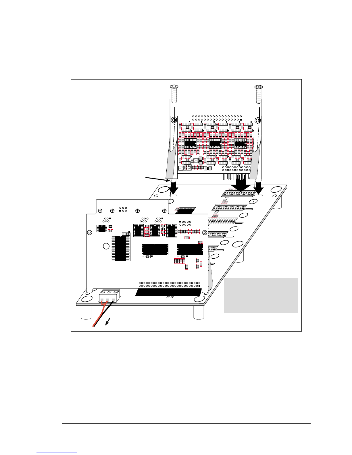
1. Orient the backplane with the CPU card already installed and facing towards you as
shown in Figure 1.
Figure 1. Installing A/D Converter Cards on the Backplane
2.
Position the A/D converter card above the backplane over any unused slot position
(
SLOT 0
to SLOT 6) as shown in Figure 1. Note the slot number and the type of I/O
card since Dynamic C addresses the I/O cards by slot number.
3. Carefully insert the A/D converter card header into the slot on the backplane and line
up the tabs on the card with the slots on the backplane as shown in Figure 1.
4. Use the two 4-40 screws supplied with the A/D converter card to ensure that the plastic
brackets anchor the relay card firmly on the backplane. Tighten the screws as needed.
+
C
2
5
C
2
7
J6
C
1
1
Place tabs on
card into
alignment slot
D3 C4
+
C5
U2
C
6
D4
L2
C
9
U5
U6
C
1
0
U7
L1
D2
C
3
U1C2C1
+
+
D1
U3
C
7
U4
C
8
R
9
R
8
R7R6R
5
R
4
R3R2R
1
3
IN
P
O
W
E
R
J1
1
52
J2
PROCESSOR SLOT
51
26
C
1
5
J3
C
1
6
C
1
3
C
1
4
C
1
8
C
1
7
SLOT 0
2
J4
C
1
9
C
2
0
C
2
1
J5
2
2
SLOT 2
C
2
3
C
2
2
SLOT 1
C
2
4
2
SLOT 3
C
2
6
J7
C
2
9
C
2
8
SLOT 4
2
C
3
0
SLOT 5
2
C
3
2
C
3
1
J8
C
3
3
J9
C
3
4
C
3
5
SLOT 6
2
25
C
1
2
21
Note: The plastic brackets
on the CPU card are
attached on the opposite
side of the board relative
to the I/O cards.
USER
GND
+RAW
U41
U44
R50
U40
C50
JP1
R51
C51
U45
JP2
C55
U43
C52
U42
U46
C57
JP3
R63
R64
R65
R66
R67
R68
C58
R62
C56
R54R55R56 R57R58R59 R60R61
C53
C54
R52
R53
Flash
EPROM
Flash
EPROM
SRAM
CPU Card
To
power supply
JP14JP16
JP13
R78
R79R81
R80
R83
JP18
R82
JP17
R84
JP20
R85
+
C45
U23
+
C46
R89
C47
R90
C48
R86
U20
C20
C32
JP15
R56
JP6
R24
JP1JP3
JP2
JP5 R23
R21
JP4
R22
R20
R32
R25JP7
R26
JP8
R27
JP9
R28
JP10
R29
U21
U22
C40
R72
JP19
C44
R71
JP11
R30
JP12
R31
C43
C31
JP21
R55
R77
R87
U24
R91
Q20
R88
JP22
A/D Converter Card
Page 8
4 Smart Star A/D Converter Cards (SR9300)
1.3 User Interface
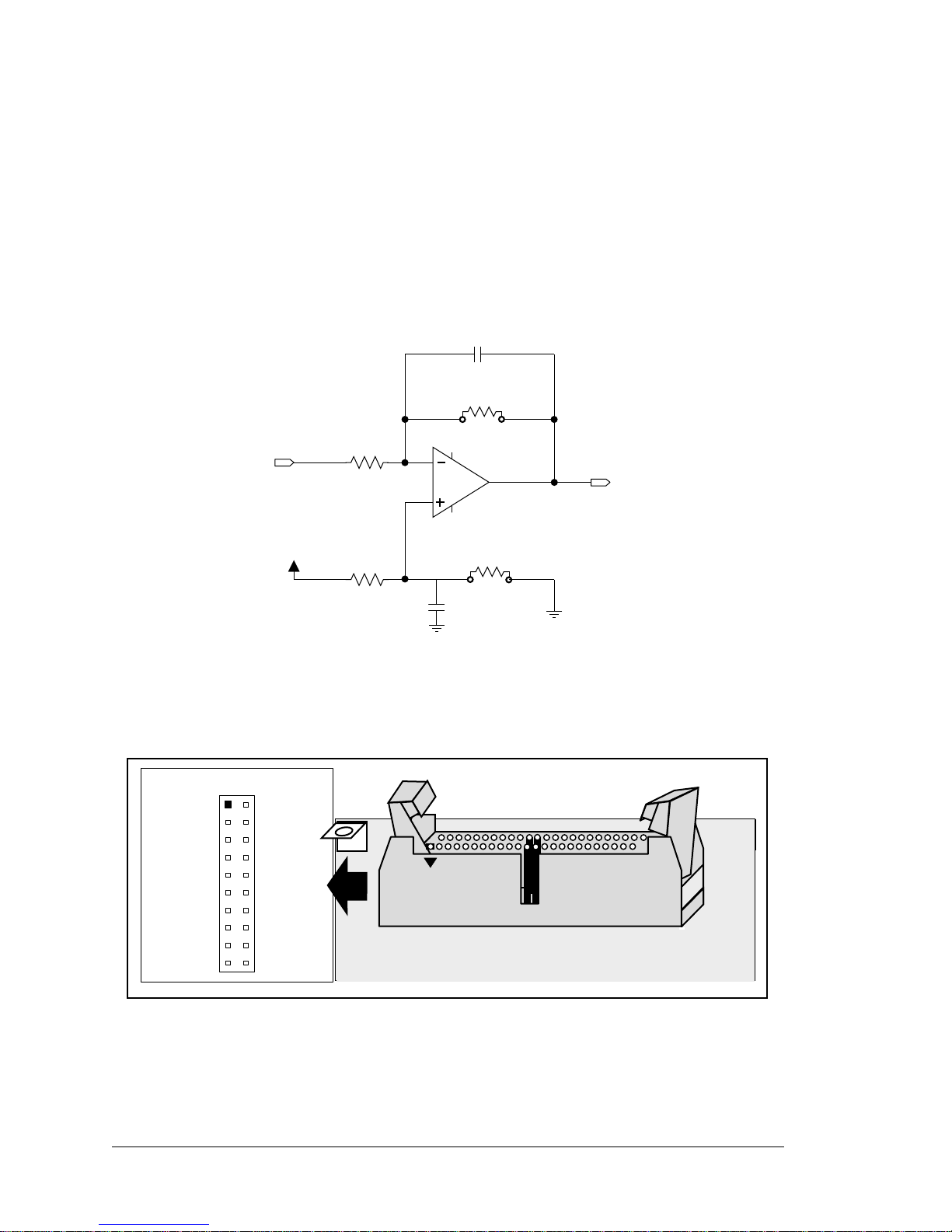
Figure 2 shows the circuit used to condition the analog signal before it goes to the A/D
converter chip. Depending on the model of A/D converter card you have, it is designed to
handle analog inputs of 0 V to 10 V, -10 V to +10 V, or 4–20 mA. The two different voltage ranges are handled with different gain resistors, Rg: 23.7 kΩ for the SR9300 and
12.1 kΩ for the SR9310. The input shown in Figure 2 is configured differently for the
SR9320, which handles analog inputs of 4–20 mA.
Figure 2. Analog Input Amplifier Circuit
Figure 3 shows the complete pinout for the user interface on header J2. Note that pin 1 is
indicated by a small arrow on the ribbon cable connector.
Figure 3. A/D Converter Card User Interface Pinout
1 nF
R
g
R
BOTTOM
R
TOP
VREF
Input
To ADC
100 kW
10 kW
R
IN
C
FB
100 nF
AIN0
GND
AIN3
AIN4
GND
GND
AIN8
AIN9
GND
GND
AIN1
AIN2
GND
AIN5
AIN6
AIN7
GND
AIN10
+5 V (ADC)
+2.5 V
J2
Page 9
User’s Manual 5
1.4 User Connections
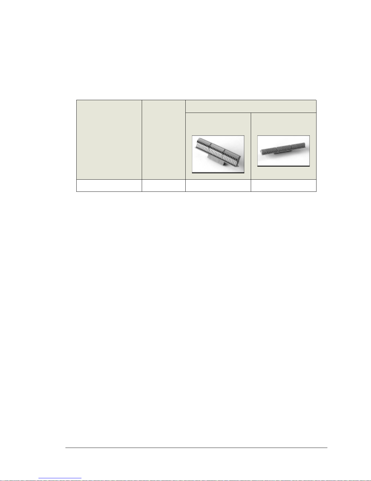
Connections to the A/D converter cards are made via a ribbon cable connector or optional
field wiring terminals that are either pluggable or have screw terminals. Table 2 lists the
the Z-World part numbers for the FWTs.
Appendix B, “Field Wiring Terminals,” provides further information on FWTs, including their dimensions and pinouts.
Table 2. Guide to FWT Selection
FWT Description I/O Cards
Z-World Part Number
Pluggable Terminals Screw Terminals
FWT18 A/D Converter 101-0421 101-0425
&
Page 10
6 Smart Star A/D Converter Cards (SR9300)
1.5 Power Distribution
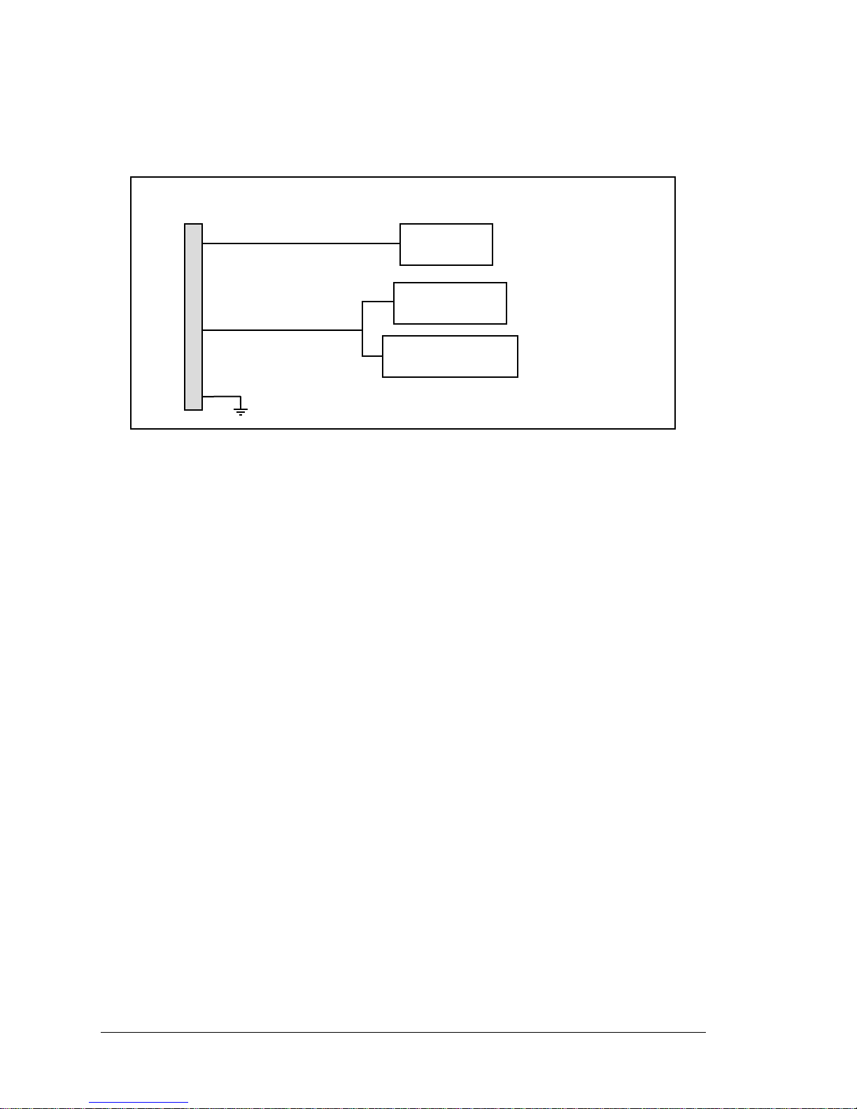
Figure 4 shows the power distribution on the A/D converter card.
Figure 4. A/D Converter Card Power Distribution
BACKPLANE
SLOT 06
20
22
1, 26
+5 V
+V_USER
Multiplexer/
Latch
Precision
+2.5 V reference
+5 V VccADC
Page 11

User’s Manual 7
2. SOFTWARE
Dynamic C Premier is an integrated development system for writing embedded software.
It runs on an IBM-compatible PC and is designed for use with Z-World controllers and
other controllers based on the Rabbit microprocessor.
Chapter 2 provides the libraries, function calls, and sample programs related to the Smart
Star A/D converter cards.
Page 12
8 Smart Star A/D Converter Cards (SR9300)
2.1 Dynamic C Libraries
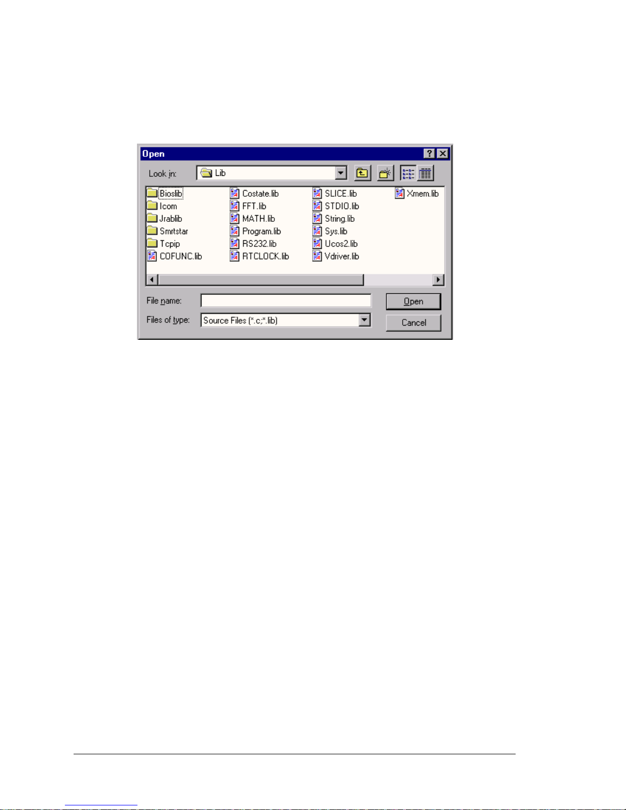
With Dynamic C running, click File > Open, and select Lib. The following list of
Dynamic C libraries and library directories will be displayed.
One library directory is specific to the Smart Star.
•
SMRTSTAR—libraries associated with features specific to the Smart Star control sys-
tem.
Other functions applicable to all devices based on the Rabbit 2000 microprocessor are
described in the Dynamic C Premier User’s Manual.
Page 13
User’s Manual 9
2.1.1 Library Directories
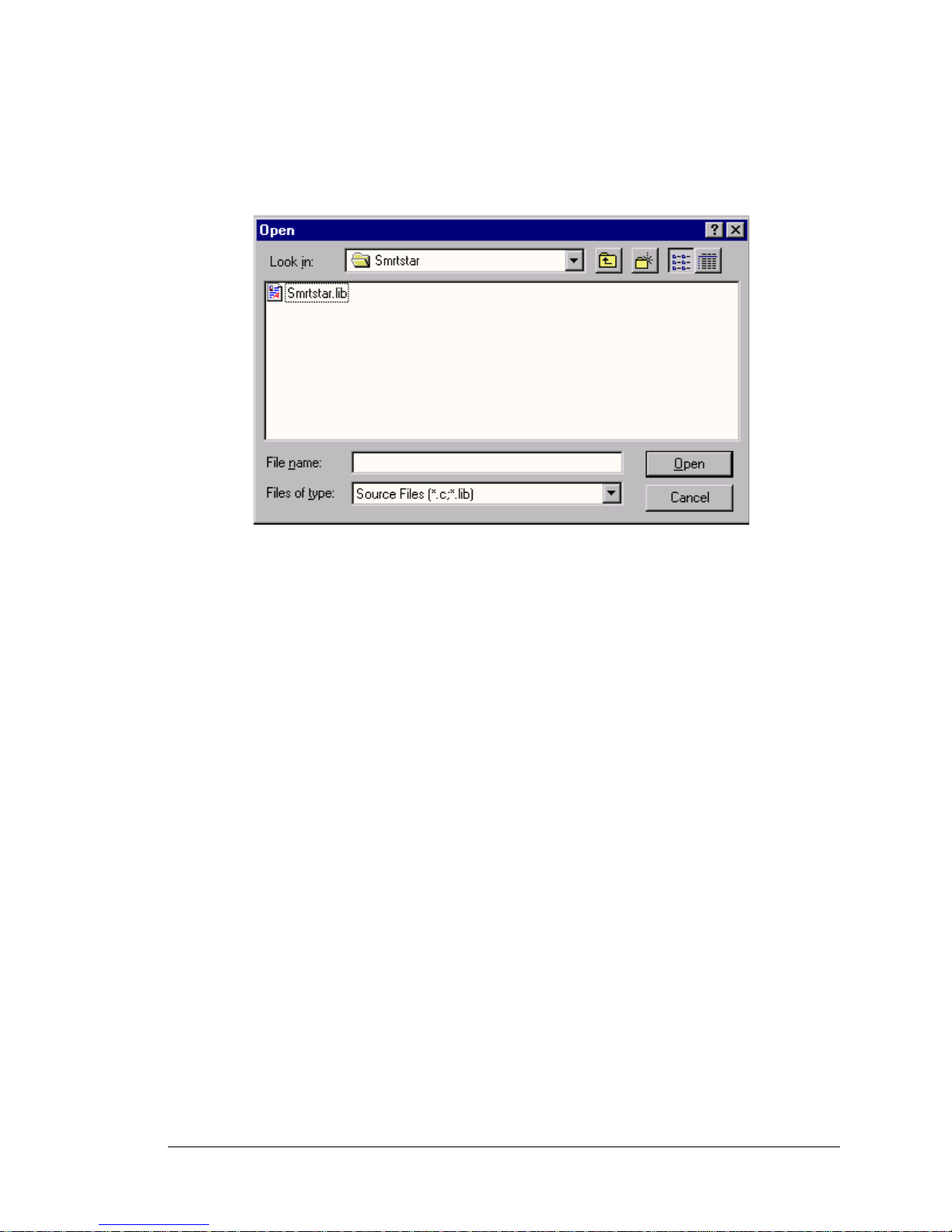
The SMRTSTAR directory contains libraries required to operate the Smart Star control system.
• SMRTSTAR.LIB—This library supports all the functions needed by the Smart Star sys-
tems including digital I/O cards, relay cards, D/A converter and A/D converter cards,
and serial communication.
Functions dealing with the A/D converter cards are described in this manual. Functions
relevant to the other I/O cards are described in the manual specific to the I/O card. Functions dealing with the backplane and the CPU card are described in the Smart Start
(SR9000) User’s Manual.
Page 14

10 Smart Star A/D Converter Cards (SR9300)
2.2 Smart Star A/D Converter Card Function APIs
The A/D converter card calibration constants, gain, and offset are stored in the factory in the
upper half of the EEPROM on the A/D converter card. Use this function to read the A/D converter card calibration constants, gain, and offset from the upper half of the EEPROM on the
A/D converter card
Parameters
channel is the analog input channel. channel should be passed as
channel = (slotnumber * 128) + (channelnumber)
where slotnumber is 0–6, and channelnumber is 0–10
or
channel = ChanAddr(slotnumber, channelnumber)
where slotnumber is 0–6, and channelnumber is 0–10.
Return Value
0 if successful.
-1—control command unacceptable.
-2—EEPRO M address unacceptable.
See Also
anaInEEWr
The calibration constants may also be saved in the flash memory on the Smart Star CPU card.
Doing so will speed up A/D conversions since a memory access from flash memory will be
faster than from EEPROM. Use anaSaveCalib to save the current se t of calibration constants for the ana log inp ut and out put ch anne ls in t he Smart S tar flash memory. The calibration
constants stored in flash memory can then be accessed at any time with the anaLoadCalib
function.
If the factory-set calibration are not used, customer-measured calibration constants should first
be established using the anaInCalib function.
Return Value
None.
See Also
anaLoadCalib, anaInCalib
int anaInEERd(int channel);
int anaSaveCalib();
Page 15

User’s Manual 11
Reads a complete se t of calibration constants for the analog input and output channels fr om the
Smart Star flash memory on the CPU card. These should be set using the anaInCalib or
anaInEERd function, then saved to flash memory using the anaSaveCalib function.
Return Value
None.
See Also
anaSaveCalib, anaInCalib
Used to recalibrate the r espons e of t he A/D co nver ter chan nel as a l inear funct ion us ing th e two
conversion points p rovide d. Gain and offset constants are calculated an d place d into t he globa l
table _adcCalib.
Parameters
channel is the A/D converter input channel (0–10). channel should be passed as
channel = (slotnumber * 128) + (channelnumber)
where slotnumber is 0–6, and channelnumber is 0–10
or
channel = ChanAddr(slotnumber, channelnumber)
where slotnumber is 0–6, and channelnumber is 0–10.
value1 is the first A/D converter value.
volt1 is the voltage corresponding to the first A/D converter value.
value2 is the second A/D converter value.
volt2 is the voltage corresponding to the first A/D converter value.
Return Value
0 if successful, -1, if not able to make calibration constants.
See Also
anaIn, anaInVolts
int anaLoadCalib();
void anaInCalib(int channel, int value1,
float volt1,int value2, float volt2);
Page 16

12 Smart Star A/D Converter Cards (SR9300)
Writes the calibration constants, gain, and offset to the upper half of the EEPROM on the A/D
converter card.
Parameters
channel is the analog input channel. channel should be passed as
channel = (slotnumber * 128) + (channelnumber)
where slotnumber is 0–6, and channelnumber is 0–10
or
channel = ChanAddr(slotnumber, channelnumber)
where slotnumber is 0–6, and channelnumber is 0–10.
Return Value
0 if successful.
-1—control command unacceptable.
-2—EEPRO M address unacceptable.
-3—data value unacceptable.
See Also
anaInEERd, _anaInEEWr
int anaInEEWr(int channel);
Page 17

User’s Manual 13
Reads the s t ate of an analog input ch annel.
Parameters
channel is the analog input channel to read. channel should be passed as
channel = (slotnumber * 128) + (channelnumber)
where slotnumber is 0–6, and channelnumber is 0–10
or
channel = ChanAddr(slotnumber, channelnumber)
where slotnumber is 0–6, and channelnumber is 0–10.
Return Value
A value corresponding to the voltage on the analog input channel, 0–4095.
See Also
anaInCalib, anaInVolts
Reads the state of an analog input channel and uses the previously set calibration constants to
convert the state to volts.
Parameters
channel is the analog input channel. channel should be passed as
channel = (slotnumber * 128) + (channelnumber)
where slotnumber is 0–6, and channelnumber is 0–10
or
channel = ChanAddr(slotnumber, channelnumber)
where slotnumber is 0–6, and channelnumber is 0–10.
Return Value
A voltage value corresponding to the voltage on the analog input channel, 0–4095.
See Also
anaIn, anaInCalib
int anaIn(int channel);
int anaInVolts(int channel);
Page 18
14 Smart Star A/D Converter Cards (SR9300)
2.3 Sample Programs
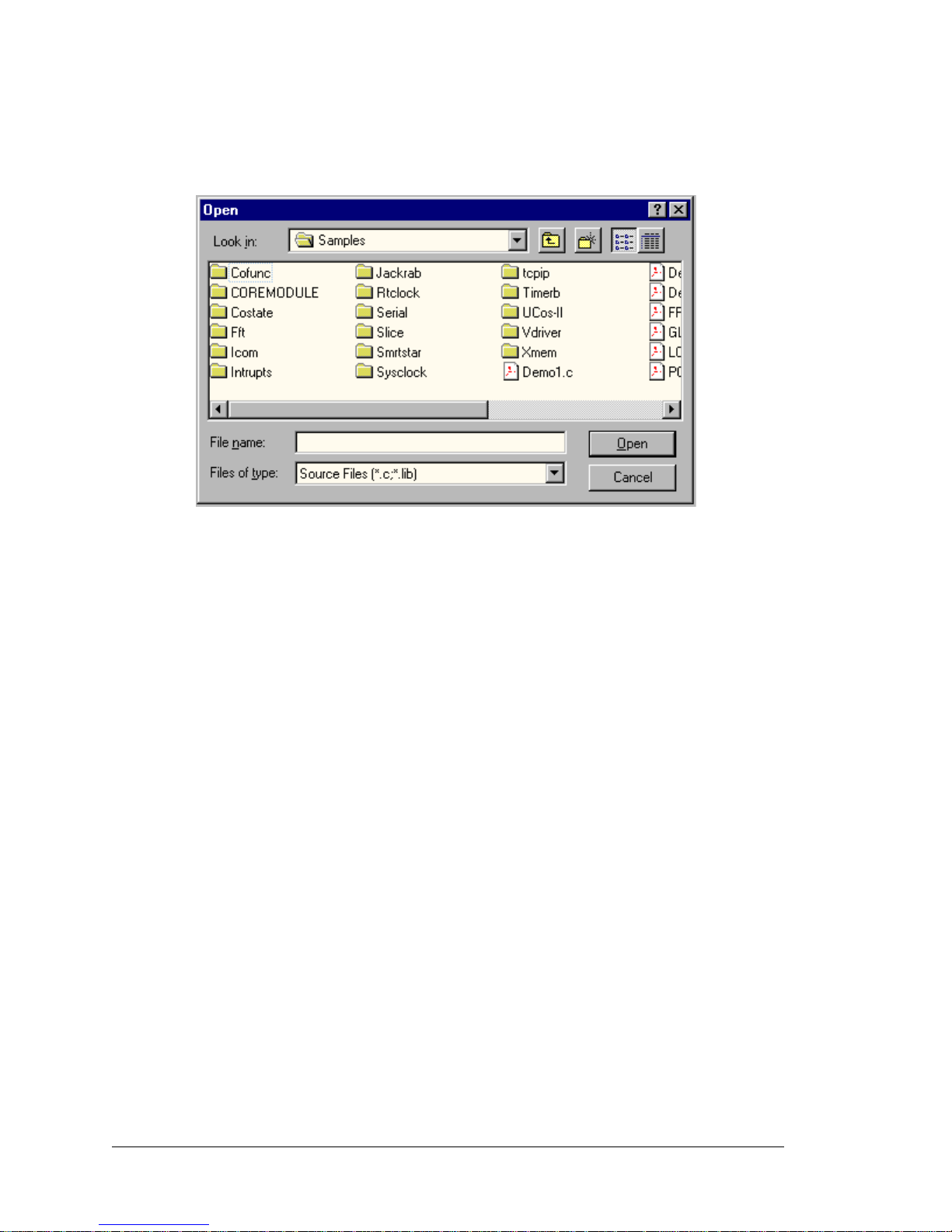
Sample programs are provided in the Dynamic C Samples folder, which is shown below.
The various folders contain specific sample programs that illustrate the use of the corresponding Dynamic C libraries. For example, the sample program
PONG.C demonstrates
the output to the STDIO window.
The
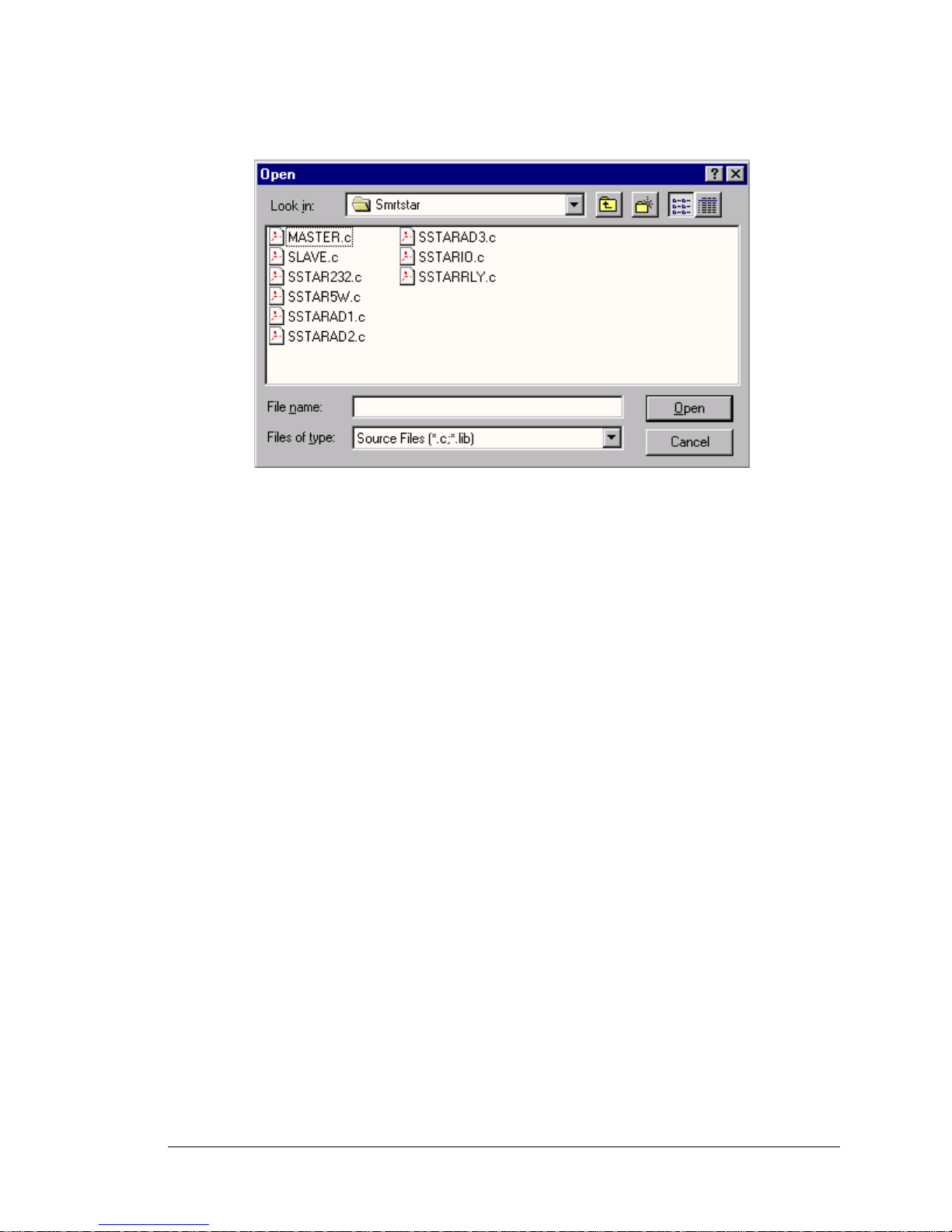
SMRTSTAR folder provides sample programs specific to the Smart Star control sys-
tem. Each sample program has comments that describe the purpose and function of the
program. Follow the instructions at the beginning of the sample program.
Page 19
User’s Manual 15
Let’s take a look at sample programs for the relay card in the
SMRTSTAR
folder .
•
SSTARAD1.C
—Demonstrates how to calibrate an A/D converter channel using two
known voltages, and defines the two coefficients, gain and offset. These coefficients are
then read back to compute the equivalent voltage.
•
SSTARAD2.C
—Reads and displays voltage and equivalent values of each A/D converter
channel. Calibrations must have been previously stored into flash memory before running this program. See sample program
SSTARAD3.C
.
•
SSTARAD3.C
—Demonstrates how to calibrate all A/D converter channels using two
known voltages and defines the two coefficients, gain and offset. These coefficients are
then read back to compute the equivalent voltage and are saved to flash memory.
2.4 Using Dynamic C
To run a sample program, open it with the File menu (if it is not still open), compile it
using the Compile menu, and then run it by selecting Run in the Run menu. The CPU
card must be in Program Mode (see Section 3.1, “Switching Between Program Mode and
Run Mode,” in the Smart Start (SR9000) User’s Manual) and must be connected to a PC
using the programming cable as described in Section 2.3, “Programming Cable Connections,” in the Smart Start (SR9000) User’s Manual.
More complete information on Dynamic C is provided in the Dynamic C Premier User’s
Manual.
Page 20

16 Smart Star A/D Converter Cards (SR9300)
Page 21

User’s Manual 17
APPENDIX A.
A/D CONVERTER CARD SPECIFICATIONS
Appendix A provides the specifications for the Smart Star A/D converter card.
Page 22
18 Smart Star A/D Converter Cards (SR9300)
A.1 Electrical and Mechanical Specifications
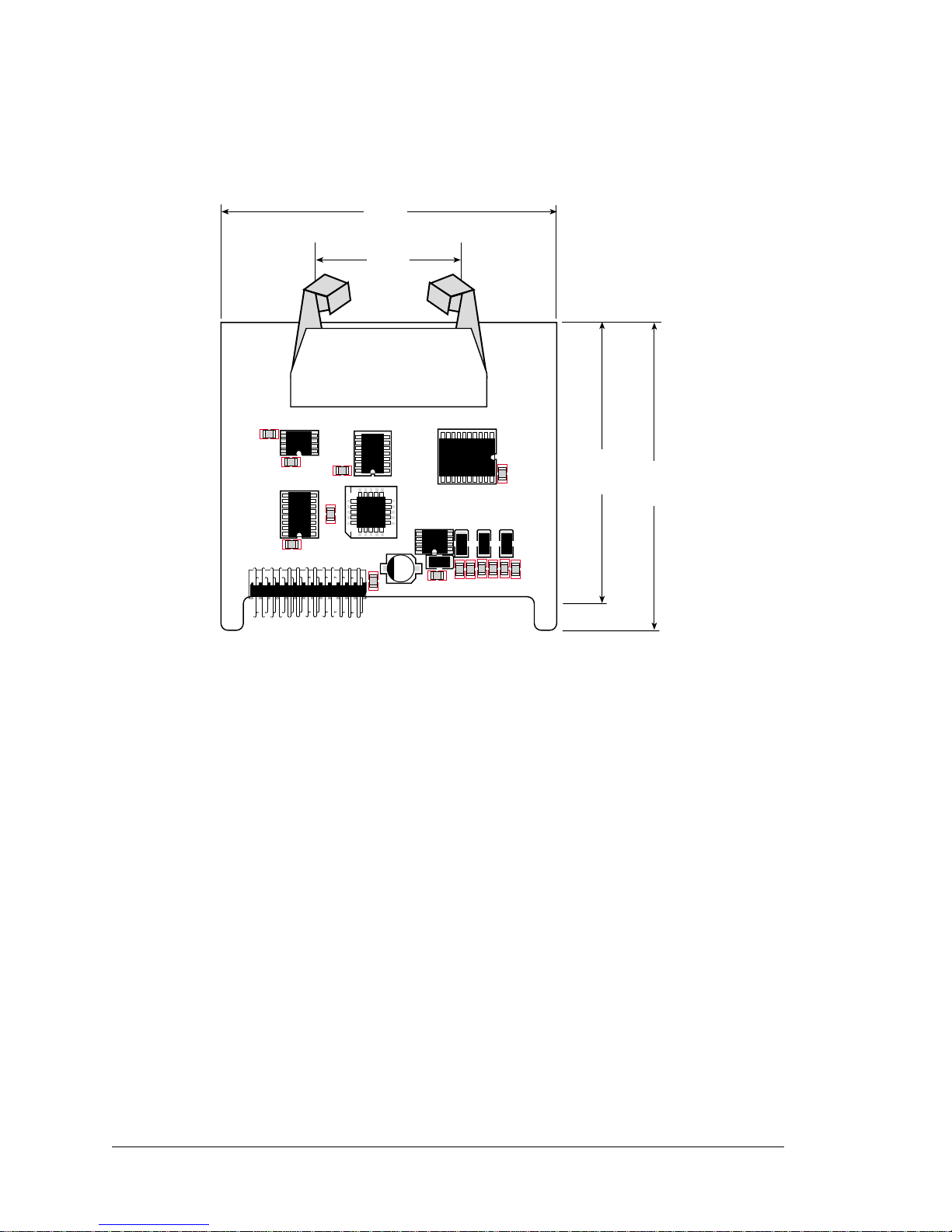
Figure A-1 shows the mechanical dimensions for the A/D converter card.
Figure A-1. Relay Card Dimensions
All diagram and graphic measurements are in inches followed by millimeters enclosed
in parentheses.
J1
C2
+
C6
U6
C12
+
C10
C11
R3
R2
C9
+
C3
C4
1
11
616
U4
U3
U2
J2
U1
R1
C1
U5
C5
+
C8
+
C7
C13
C14
R4
R5
2.73
(70)
2.49
(63)
3.00
(76)
1.19
(48)
!
Page 23
User’s Manual 19
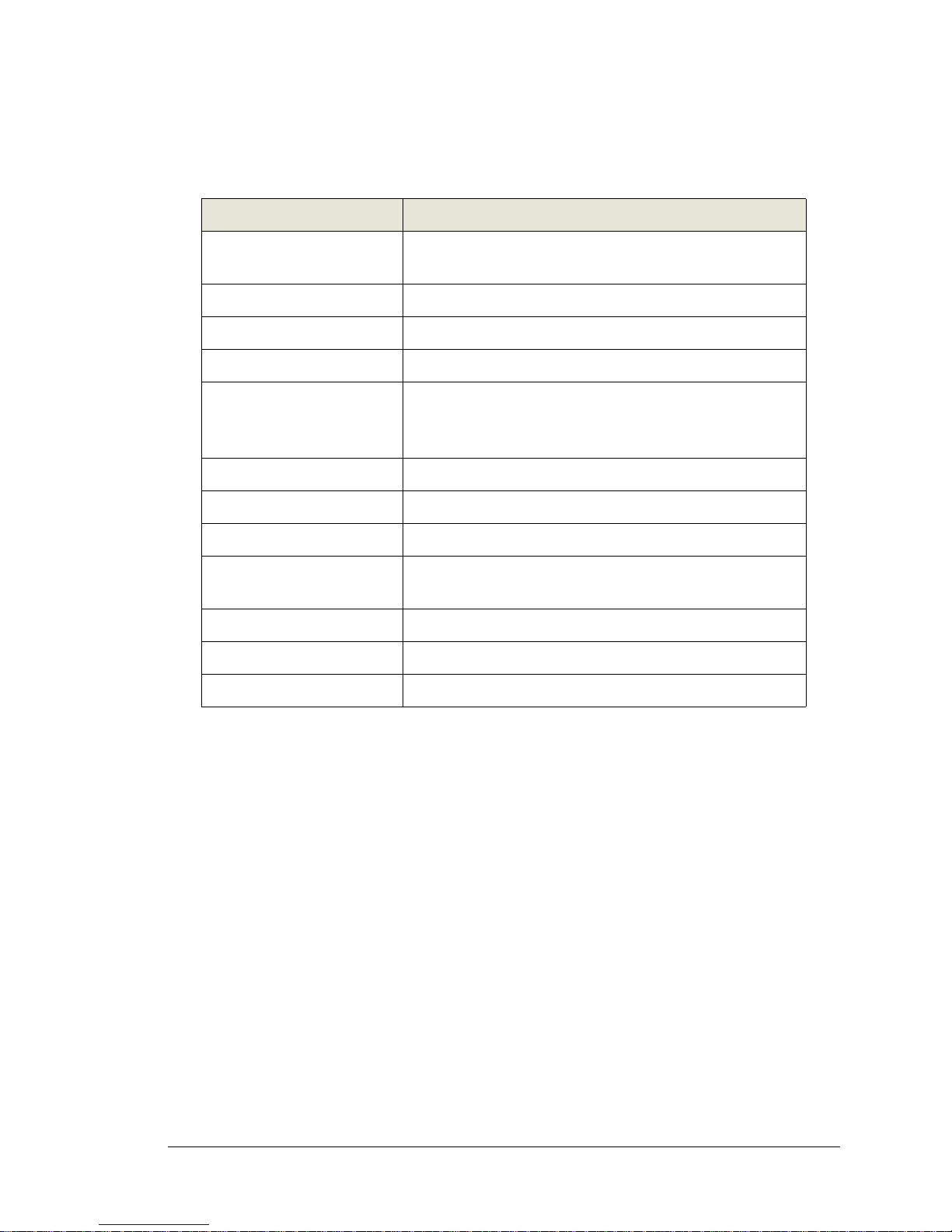
Table A-1 lists the electrical, mechanical, and environmental specifications for the A/D
converter card.
Table A-1. A/D Converter Card Specifications
Parameter Specification
Board Size
2.73" × 3.00" × 0.44"
(70 mm × 76 mm × 11 mm)
Connectors one 2 × 10 latch/eject ribbon connector, 0.1 inch pitch
Operating Temperature –40°C to +7 0 °C
Humidity 5% to 95%, noncondensing
Power Requirements
5 V DC at 40 mA from backplane (+5 V supply)
9 V to 30 V DC, 35 mA at 24 V DC, +RAW/+V_USER
from backplane
Number of Inputs 11 conditioned channels
Analog Input Ranges 0 V to +10 V, -10 V to +10 V, 4 mA to 20 mA
Resoluti on 12 bits (0–4095)
Conversion Time
(including Dynamic C)
0.2 ms/channel
Input Stability ±½ count
Input Impedance 100 kΩ min. for 0 V to +10 V range
Linearity Error (end to end) ±1 count
Page 24

20 Smart Star A/D Converter Cards (SR9300)
Page 25

User’s Manual 21
APPENDIX B.
FIELD WIRING TERMINALS
Appendix B explains how to prepare the connector on an I/O card to accept a field wiring
terminal, and how to secure the field wiring terminal to the I/O card. The dimensions for
the field wiring terminals are included.
Page 26
22 Smart Star A/D Converter Cards (SR9300)
B.1 Selecting and Installing a Field Wiring Terminal
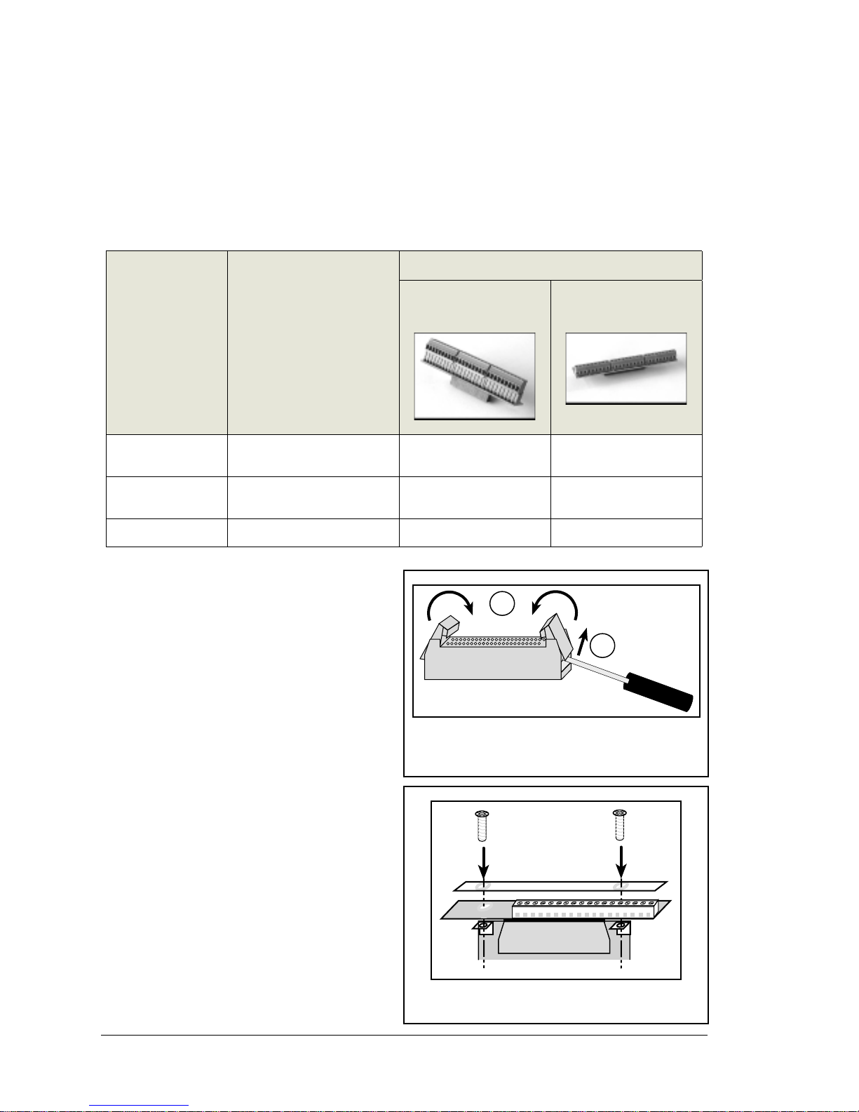
Connections to the I/O cards are made via a ribbon cable connector or optional field wiring terminals that are either pluggable or have screw terminals. Three different Field Wi ring Terminals (FWTs) are available. Table B-1 lists the I/O cards and the Z-World part
numbers for the corresponding FWTs.
Before you can install the FWT you selected
for your I/O card, you must remove the tabs
from the connector on the I/O card. To do
so, move the tab inwards as shown in
Figure B-1. Then insert a screwdriver into
the space below the tab on the side of the
connector and gently nudge the tab up and
out. If you are careful, the tab will remain
intact to be saved and snapped back in place
for future use.
Plug the FWT connector into the connector
on the A/D converter card. Be sure to position the pluggable or screw connectors so
that the edge of the FWT they are on faces
outwards from the A/D converter card as
shown in Figure B-2. Position the mylar
insulator above the FWT as shown in
Figure B-2 to protect the header pins on the
printed circuit board, and secure the FWT
using the two 4-40 × ¼ screws supplied.
Table B-1. Guide to FWT Selection
FWT Description I/O Cards
Z-World Part Number
Pluggable Terminals Screw Terminals
FWT27
Digital I/O (SR9200 series)
Relay (SR9510)
101-0420 101-0424
FWT18
A/D Converter (SR9300 series)
D/A Converter (SR9400 series)
101-0421 101-0425
FWT18R
Relay (SR9500)
101-0422 101-0426
Figure B-1. Remove Tabs from Connector
on I/O Card
1
2
Figure B-2. Secure FWT to I/O Card
Mylar insulator
Page 27
User’s Manual 23
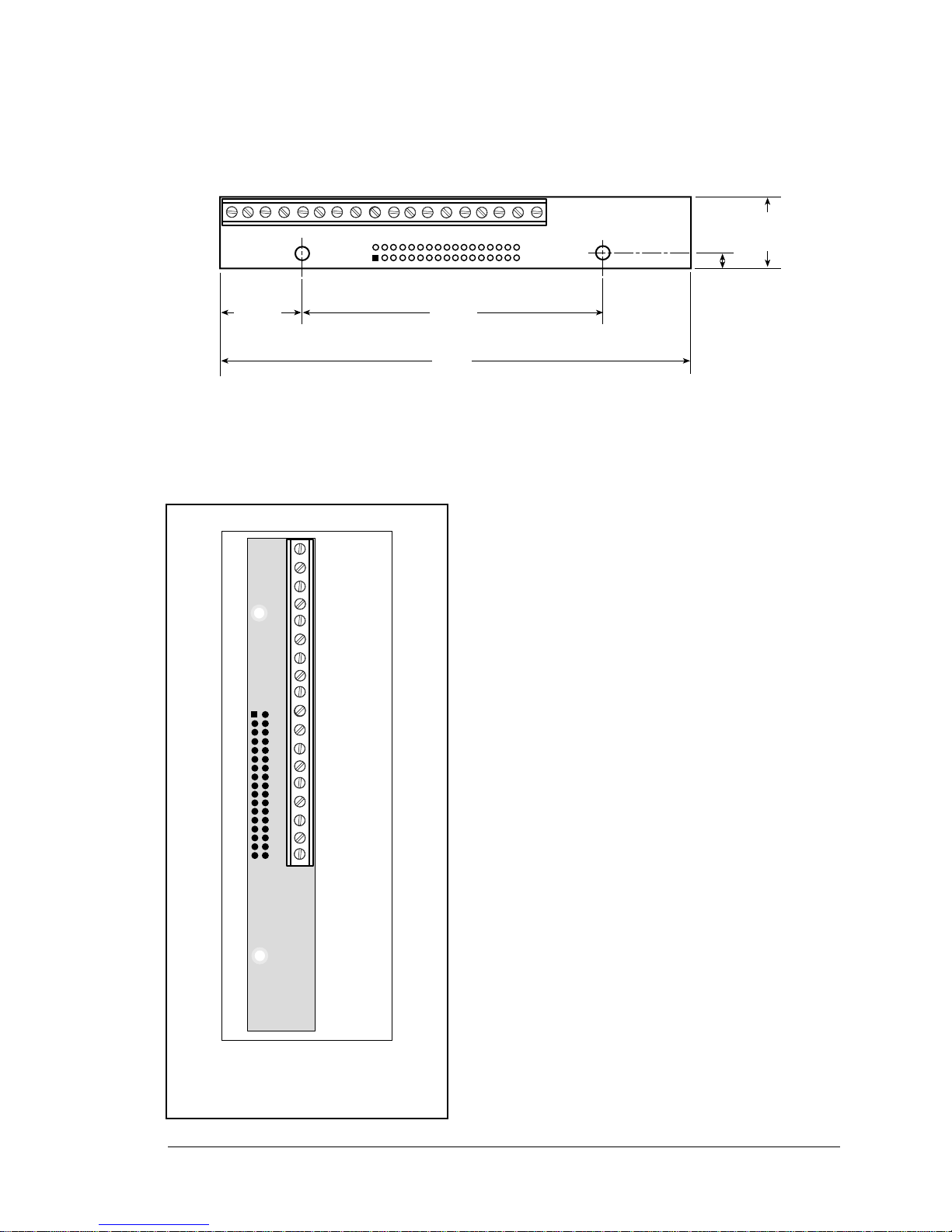
B.2 Dimensions
Figure B-3 shows the FWT dimensions.
Figure B-3. FWT Dimensions
All diagram and graphic measureme nts are in inc hes followed by millimeters enclosed
in parentheses.
B.3 Pinouts
Figure B-4 shows the pinout for the FWTs used on
the A/D converter cards. Note that AIN0 is not
available when using a FWT.
0.125
(3.2)
4.20
(107)
2.75
(70)
0.625
(16)
0.725
(18.5)
!
Figure B-4. FWT Pinout for
A/D Converter Cards
GND
AIN2
GND
AIN2
AIN3
GND
AIN4
AIN5
GND
AIN6
GND
AIN7
AIN8
GND
AIN9
AIN10
GND
+5 V (ADC)
1
2
3
4
5
6
7
8
9
10
11
12
13
14
15
16
17
18
Page 28

24 Smart Star A/D Converter Cards (SR9300)
Page 29

User’s Manual 25
APPENDIX C.
SMART STAR SLOT ADDRESS LAYOUT
Appendix C provides information about the register addresses for the various I/O card
slots on the backplane. The information in this appendix will be of interest to more
advanced users.
Page 30
26 Smart Star A/D Converter Cards (SR9300)
The slots on the Smart Star backplane are accessed as external registers via the Rabbit
2000’s assembly IOE prefix or via standard Rabbit BIOS functions. More convenient
functions specific to the Smart St ar control system have been written to provide more flexibility; for example, there is now a provision for the automatic update of shadow registe rs
for each slot and for each register.
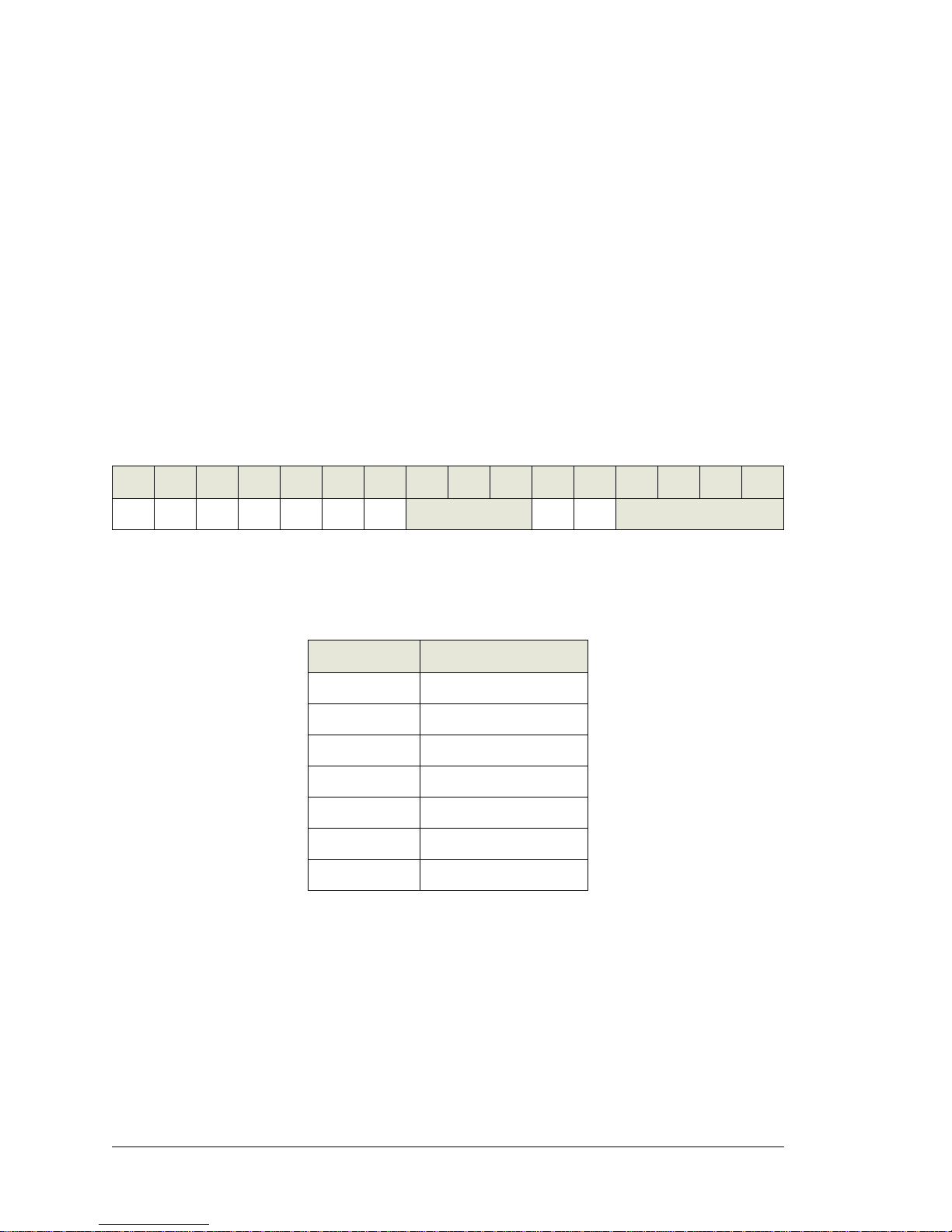
The Smart Star design routes four address bits to each slot, providing 16 register addresses
for each slot. These bits are passed through as bits 0–3 of the register address. The slot
number itself is assigned to bits 6–8 of the address. In addition, the backplane design
requires that bits 13 and 14 be high and that bit 9 be low. The simplest way to enforce this
is to use a base address of 0x6000. Table C-1 provides the address layout for accessing
the Smart Star backplane slots, where Sn is the binary representation of the slot number
(0–6), Rn is the binary representation of the register numbers (0–15), and X means the
value does not matter.
This bit mapping of the external register address provides the register addresses for each
slot as listed in Table C-2.
Table C-1. Smart S tar External Register Address Bitmap
A15 A14 A13 A12 A11 A10 A9 A8 A7 A6 A5 A4 A3 A2 A1 A0
0110XX0
S2 S1 S0 XXR3 R2 R1 R0
Table C-2. Slot External Register Addresses
Slot Number Address Range
0 0x6000–0x600F
1 0x6040–0x604F
2 0x6080–0x608F
3 0x60C0–0x60CF
4 0x6100–0x610F
5 0x6140–0x614F
6 0x6180–0x618F
Page 31
User’s Manual 27
C.1 A/D Converter Card Channel Layout
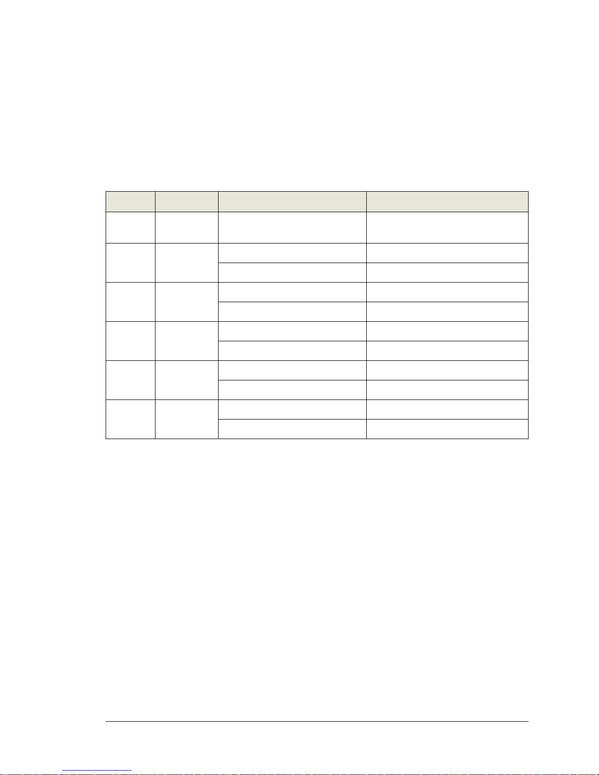
The A/D converter card contains a single 11-input 12-bit A/D converter, TLC2543. The
method of interfacing to this chip is a combination of single-bit writes via board registers
and synchronous clocked serial access via the CPU card’s serial port B, which is extended
across all eight slots. In addition, a serial EEPROM is installed on the A/D converter card
to store the calibration constants.
Table C-3. A/D Converter Card Control Registers
Address Data Bits Value Description
0x0 Write D7–D0
D7–D4 selects input channel,
D3–D0 selects conversion channel
Load A/D converter with data byte
0x0 Read D1
0 A/D converter end of conversion signal
1 A/D converter busy
0x1 Write D0
0 Enable A/D conversion
1 Disable A/D conversion
0x2 Write D0
0 EEPROM clock line low
1 EEPROM clock line high
0x3 Write D0
0 EEPROM data line low
1 EEPROM data line high
0x0 Read D2
0 EEPROM acknowledge signal
1EEPROM busy
Page 32

28 Smart Star A/D Converter Cards (SR9300)
Page 33

User’s Manual
A
A/D converter cards
models ..................................2
analog input conditioning circuit
4
D
dimensions
A/D converter card .............18
field wiring terminals .........23
Dynamic C Premier ...............15
basic instructions ................15
libraries ................................8
F
features .....................................2
field wiring terminals .............22
A/D convertre card pinout .23
dimensions .........................23
guide to FWT selection ..5, 22
installation ..........................22
positioning on I/O card ......22
remove tabs on I/O card con-
nector .............................22
FWT. See field wir ing termin als
I
I/O cards
attaching to backplane .........3
installation
field wiring terminals .........22
I/O cards ...............................3
P
pinout
A/D converter card user inter-
face ..................................4
FWT18 field wiring terminal .
23
power distribution ....................6
S
sample programs ....................14
SSTARAD1.C ...................15
SSTARAD2.C ..................15
SSTARAD3.C ...................15
slot address layout .................25
software ...................................8
libraries ................................8
SMRTSTAR.LIB .........8, 9
sample programs ................14
SMRTSTAR.LIB
anaIn ............................ 13
anaInCalib ................11
anaInEERd ..................10
anaInEEWr ..................12
anaInVolts ................13
anaLoadCalib ...........11
anaSaveCalib ...........10
specifications .........................17
A/D converter card
dimensions .....................18
electrical .........................19
temperature ....................19
field wiring terminals
dimensions .....................23
INDEX
Page 34

30 Smart Star A/D Converter Cards (SR9300
Page 35

User’s Manual 31
SCHEMATICS
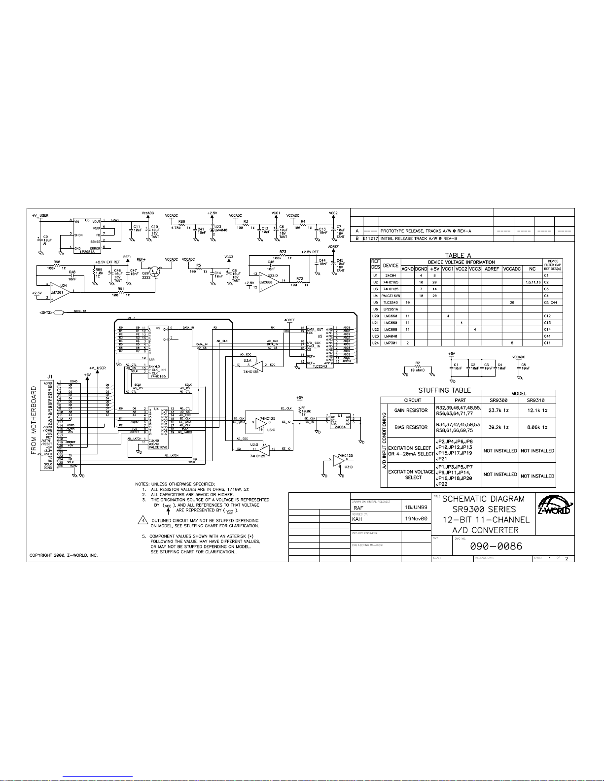
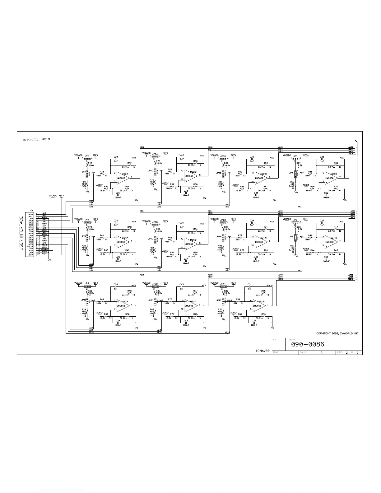
090-0086 A/D Converter Card (SR9300) Schematic
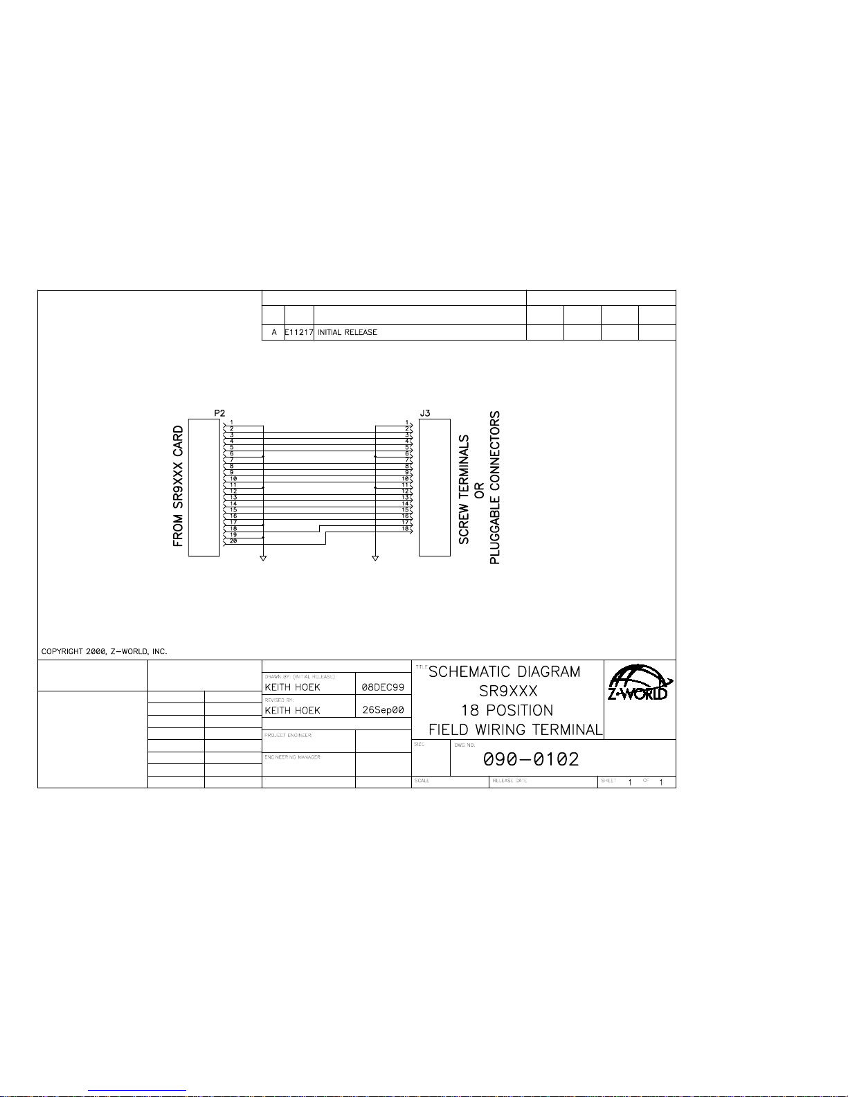
090-0102 FWT18 Schematic
Page 36
THIS DOCUMENT:
APPEND THE FOLLOWING
DOCUMENTS WHEN CHANGING
ECO
APPROVAL APPROVAL
CONTROL
DOCUMENT
DATE
REVISION HISTORY
ENGINEER
PROJECT
DATE
REV
DESCRIPTION
REVISION APPROVAL
NONEDATE
B
DRAWING CONTENT:
APPROVALS: INITIAL RELEASE
SIGNATURES
2900 SPAFFORD ST.
DAVIS, CA 95616
530 - 757 - 4616
Page 37
B
NONE
Page 38
SIGNATURES
APPROVALS: INITIAL RELEASE
DRAWING CONTENT:
THIS DOCUMENT:
APPEND THE FOLLOWING
DOCUMENTS WHEN CHANGING
ECO
REVISION HISTORY
REV
ENGINEER
PROJECT
DESCRIPTION
REVISION APPROVAL
APPROVAL APPROVAL
CONTROL
DOCUMENT
DATE
DATE
A
DATE NONE
530 - 757 - 4616
DAVIS, CA 95616
2900 SPAFFORD ST.
Page 39

 Loading...