

Page 1
Wolf (BL2600)
C-Programmable Singl e-Boar d Comp ut er with Et hern et
User’s Manual
019–0142 • 040731–B
Page 2

Wolf (BL2600)
Z-World, Inc.
2900 Spafford Street
Davis, California 95616-6800
USA
Tel e phone: (530) 757-3737
Fax: (530) 753-5141
www .zworld.com
Wolf (BL2600) User’s Manual
Part Number 019-0142 • 040731–B • Printed in U.S.A.
©2004 Z-World Inc. • All rights reserved.
Z-World reserves the right to make changes and
improvements to its products without providing n otice.
T r ade mark s
Rabbit and Rabbit 3000 are registered trademarks of Rabbit Semico nductor.
RabbitNet is a trademark of Z-World Inc.
Dynamic C is a registered trademark of Z-World Inc.
Page 3

User’s Manual
TABLE OF CONTENTS
Chapter 1. Introduction 1
1.1 BL2600 Description..............................................................................................................................1
1.2 BL2600 Features...................................................................................................................................1
1.2.1 Connector Options........................................................................................................................2
1.3 Development and Evaluation Tools......................................................................................................3
1.3.1 Tool Kit.........................................................................................................................................3
1.3.2 Software........................................................................................................................................4
1.3.3 Additional Tools ...........................................................................................................................4
Chapter 2. Getting Started 5
2.1 Preparing the BL2600 for Development...............................................................................................5
2.2 BL2600 Connections............................................................................................................................6
2.2.1 Hardware Reset.............................................................................................................................7
2.3 Installing Dynamic C............................................................................................................................8
2.4 Starting Dynamic C ..............................................................................................................................9
2.5 PONG.C..............................................................................................................................................10
2.6 Where Do I Go From Here? ...............................................................................................................10
2.6.1 Real-Time Clock.........................................................................................................................10
Chapter 3. Subsystems 11
3.1 BL2600 Pinouts..................................................................................................................................12
3.1.1 Connector Options......................................................................................................................12
3.2 Digital I/O...........................................................................................................................................14
3.2.1 Digital Inputs...............................................................................................................................14
3.2.2 PWM Outputs .............................................................................................................................15
3.2.3 High-Current Digital Outputs.....................................................................................................16
3.2.4 Configurable I/O.........................................................................................................................18
3.3 Serial Communication ........................................................................................................................20
3.3.1 RS-232 ........................................................................................................................................20
3.3.2 RS-485 ........................................................................................................................................20
3.3.3 Programming Port.......................................................................................................................22
3.3.4 Ethernet Port ...............................................................................................................................23
3.4 A/D Converter Inputs..........................................................................................................................24
3.4.1 A/D Converter Calibration..........................................................................................................25
3.5 D/A Converter Outputs .......................................................................................................................26
3.5.1 D/A Converter Calibration..........................................................................................................27
3.6 Analog Reference Voltage Circuit......................................................................................................28
3.7 Programming Cable............................................................................................................................29
3.7.1 Switching Between Program Mode and Run Mode....................................................................29
3.7.2 Detailed Instructions: Changing from Program Mode to Run Mode..........................................29
3.7.3 Detailed Instructions: Changing from Run Mode to Program Mode..........................................29
3.8 Other Hardware...................................................................................................................................30
3.8.1 Clock Doubler.............................................................................................................................30
3.8.2 Spectrum Spreader......................................................................................................................30
3.9 Memory...............................................................................................................................................31
3.9.1 SRAM .........................................................................................................................................31
3.9.2 Flash Memory.............................................................................................................................31
3.9.3 Serial Flash..................................................................................................................................31
Page 4

Wolf (BL2600)
Chapter 4. Software 33
4.1 Running Dynamic C........................................................................................................................... 33
4.1.1 Upgrading Dynamic C................................................................................................................34
4.2 Sample Programs................................................................................................................................ 35
4.2.1 Digital I/O...................................................................................................................................35
4.2.2 Serial Communication................................................................................................................36
4.2.3 A/D Converter Inputs.................................................................................................................37
4.2.4 D/A Converter Outputs...............................................................................................................38
4.2.5 Use of BL2600 with SF1000 Serial Flash Card.........................................................................39
4.2.6 TCP/IP Sample Programs...........................................................................................................39
4.3 BL2600 Libraries...............................................................................................................................39
4.4 BL2600 Function APIs....................................................................................................................... 40
4.4.1 Board Initialization.....................................................................................................................40
4.4.2 Digital I/O...................................................................................................................................41
4.4.3 Serial Communication................................................................................................................49
4.4.4 A/D Converter Inputs.................................................................................................................51
4.4.5 D/A Converter Outputs...............................................................................................................58
Chapter 5. Using the TCP/IP Features 63
5.1 TCP/IP Connections...........................................................................................................................63
5.2 TCP/IP Sample Programs...................................................................................................................65
5.2.1 How to Set IP Addresses in the Sample Programs.....................................................................65
5.2.2 How to Set Up your Computer’s IP Address for a Direct Connection ......................................66
5.2.3 Run the
PINGME.C Demo...................................................................................................... 67
5.2.4 Running More Demo Programs With a Direct Connection .......................................................68
5.3 Where Do I Go From Here?...............................................................................................................68
Appendix A. Specifications 69
A.1 Electrical and Mechanical Specifications..........................................................................................70
A.1.1 Exclusion Zone..........................................................................................................................72
A.1.2 Headers......................................................................................................................................73
A.2 Conformal Coating............................................................................................................................74
A.3 Jumper Configurations......................................................................................................................75
A.4 Use of Rabbit 3000 Parallel Ports.....................................................................................................77
Appendix B. Power Supply 79
B.1 Power Supplies..................................................................................................................................79
B.1.1 Power for Analog Circuits.........................................................................................................80
B.2 Batteries and External Battery Connections....................................................................... ...............80
B.2.1 Replacing the Backup Battery...................................................................................................80
Appendix C. Demonstration Board 81
C.1 Connecting Demonstration Board...................................................................... ..... ..........................81
Appendix D. RabbitNet 85
D.1 General RabbitNet Description.........................................................................................................85
D.2 Physical Implementation...................................................................................................................87
D.2.1 Control and Routing..................................................................................................................87
D.3 Function Calls....................................................................................................................................88
D.3.1 Status Byte.................................................................................................................................94
Notice to Users 95
Index 97
Schematics 101
Page 5

User’s Manual 1
1. INTRODUCTION
The BL2600 is a high-performance, C-programmable singleboard computer that offers built-in digital and analog I/O combined with Ethernet connectivity in a compact form factor. The
BL2600 is ideal for both discrete manufacturing and processcontrol applications.
A Rabbit 3000
®
microprocessor operating at 44.2 MHz provides
fast data processing with 10/100Base-T Ethernet connectivity.
Onboard serial flash options support full directory file structures
to maximize remote access control and programmability. The
I/O can be expanded with RabbitNet peripheral cards.
1.1 BL2600 Description
The BL2600 is an advanced single-board computer that incorporates the powerful Rabbit
3000 microprocessor, flash memory, serial flash, static RAM, digital I/O ports, A/D converter inputs, D/A converter outputs, RS-232/RS-485 serial ports, and a 10/100Base-T
Ethernet port.
1.2 BL2600 Features
• Rabbit 3000® microprocessor operating at 44.2 MHz.
• 512K static RAM and 512K flash memory standard
• 36 digital I/O: 16 protected digital inputs, 4 high-current digital outputs software-
configurable as sinking or sourcing, and 16 I/O individually software-configurable as
inputs or sinking outputs.
• 12 analog channels: eight 11-bit A/D converter inputs, four 12-bit D/ A converter 0 –10 V
or ±10 V buffered outputs.
• One RJ-45 Ethernet port compliant with IEEE 802.3 standard for 10/100Base-T
Ethernet protocol.
• Three Ethernet status LEDs (BL2600 only).
• Three serial ports (2 RS-232 or 1 RS-232 with RTS/CTS, 1 RS-485 or RS-232).
Page 6
2 Wolf (BL2600)
• Two RabbitNet™ expansion ports.
• Battery-backed real-time clock.
• Watchdog supervisor.
Two BL2600 models are available. Their standard features are summarized in Table 1.
The BL2600 consists of a main board with a RabbitCore module. Refer to the RabbitCore
module manuals, available on Z-World’s Web site
, for more information on the Rabbit-
Core modules, including their schematics.
The BL2600 is programmed over a standard PC serial port through a programming cable
supplied with the Tool Kit, and can also be programed throug h a US B port with an
RS-232/USB converter , or over an Ethernet with the RabbitLink (both available from Z-W orld).
Appendix A provides detailed specifications.
1.2.1 Connector Options
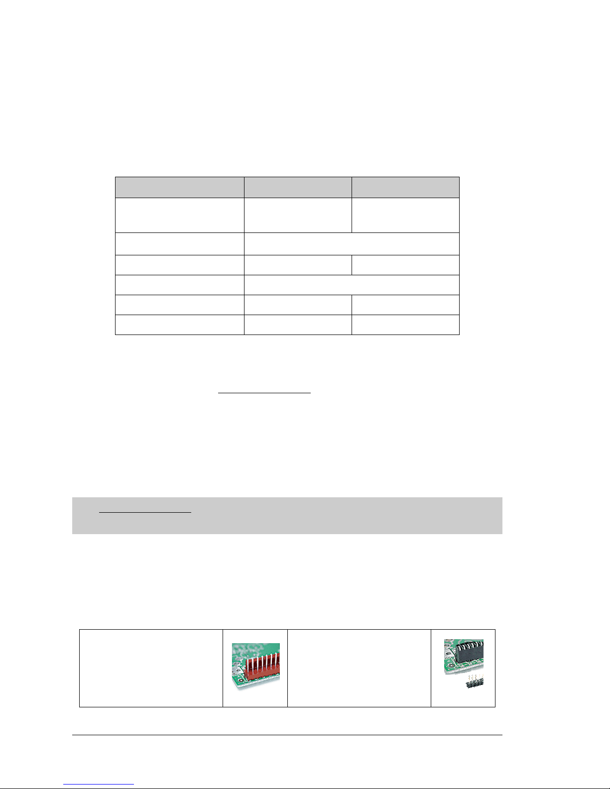
In addition to the standard polarized friction-lock connectors supplied on BL2600 boards,
dual-entry 0.1" IDC sockets can be used to connect to the BL2600 either from the top or
the bottom.
Table 1. BL2600 Models
Feature BL2600 BL2610
Microprocessor
Rabbit 3000
®
running at
44.2 MHz
Rabbit 3000® running at
29.4 MHz
Program Execution SRAM
512K
*
* 256K flash/128 K SRAM options available for BL2610
Data SRAM 256K —
Flash Memory 512K
Ethernet Port 10/100Ba se-T, 3 LEDs —
RabbitCore Module Used RCM3200
RCM3100
Vi sit Z-World’s Web site for up-to-date information about additional add-ons and features
as they become available. The Web site also has the latest revision of this user’s manual.
Standard polarized friction-lock
terminals, 0.1" pitch
0.1" IDC sockets can accept
header pins from either top or
bottom
Page 7
User’s Manual 3
1.3 Development and Evaluation Tools
1.3.1 Tool Kit
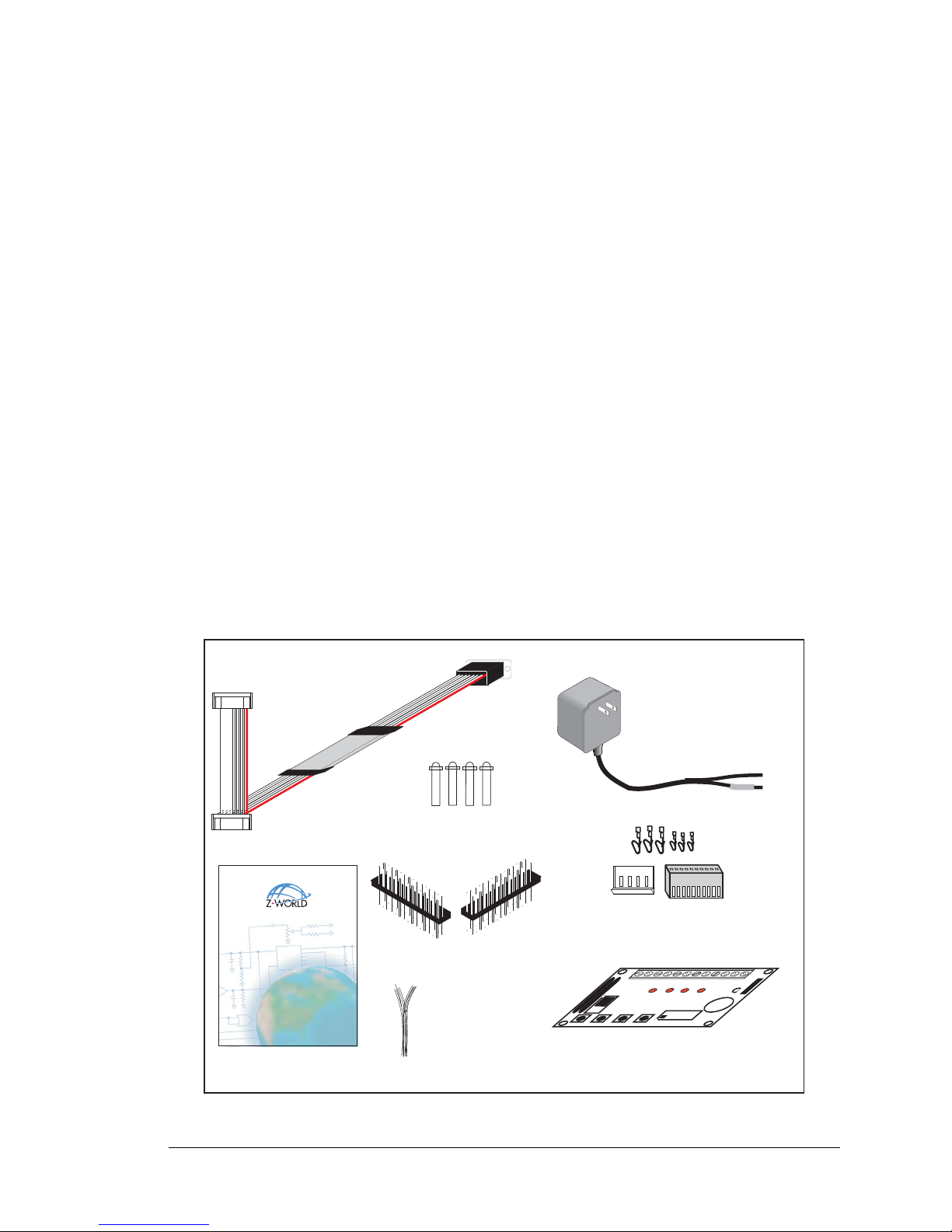
A T ool Kit contains the hardware essentials you will need to use your own BL2600 singleboard computer. The items in the Tool Kit and their use are as follows.
• BL2600 User’s Manual with schematics (this document).
• Dynamic C CD-ROM, with complete product documentation on disk.
• Programming cable, used to connect your PC serial port to the BL2600.
• Power supply , used to power the BL2600
. If you are using another power supply, it must
provide 9 to 36 V DC at 12 W
.
• Stand-offs to serve as legs for the BL2600 board during development.
• Demonstration Board with pushbutton switches and LEDs. The Demonstration Board
can be hooked up to the BL2600 to demonstrate the I/O and the TCP/IP capabilities of
the BL2600.
• Wire assembly to connect Demonstration Board to BL2600.
• Connector pins and parts to build your own wire assemblies: 0.1" crimp terminals;
0.156" crimp terminals; 1 × 4, 1 × 10, and 1 × 13 friction-lock connectors.
• Rabbit 3000 Processor Easy Reference poster.
• Registration card.
Figure 1. BL2600 Tool Kit
Dingo (BL2600)
C-Programmable Single-Board Computer with Ethernet
User’s Manual
019–0138 • 040331–A
PROG
DIAG
Programming
Cable
Plastic Stand-Offs
User's Manual
Demo Board
Power Supply
(North American
kits only)
Friction-Lock Connectors
& Crimp Terminals
Demo Board
Wiring Harness
·
B
U
Z
Z
E
R
·
L
E
D
4
·
L
E
D
3
·
L
E
D
2
·
L
E
D
1
·
K
·
+
5
V
·
S
W
4
·
S
W
3
·
S
W
2
·
S
W
1
·
G
N
D
BUZZER
H
1
J
1
H2
· ·
1-2
· ·
3-4
· ·
5-6
LED1 LED2 LED3 LED4
SW1 SW2 SW3 SW4
·
·
8
-
7
·
·
6
5
·
·
4
3
·
·
2
1
DEMO BOARD
Connector Pins
Page 8

4 Wolf (BL2600)
1.3.2 Software
The BL2600 is programmed using version 8.51 or later of Z-World’s Dynamic C. A com-
patible version is included on the Tool Kit CD-ROM.
Z-World also offers add-on Dynamic C modules for purchase containing the popular
µC/OS-II real-time operating system, as well as PPP, Advanced Encryption Standard
(AES), and other select libraries. In addition to the Web-based technical support included
at no extra charge, a one-year telephone-based technical support module is also available
for purchase. Visit our Web site at www.zworld.com
or contact your Z-World sales repre-
sentative or authorized distributor for further information.
1.3.3 Additional Tools
Z-World also has available additional programming tools and parts to help you to make
your own wiring assemblies with the friction-lock connectors.
• An RS-232/USB converter cable (Z-World Part No. 540-0070) is available for use with
the programming cable supplied with the Tool Kit. You will need such a converter if
your PC only has a USB port.
• Crimp tool (Z-World Part No. 998-0013) to secure wire in crimp terminals.
Visit our Web site at www.zworld.com
or contact your Z-World sales representative or
authorized distributor for further information.
Page 9
User’s Manual 5
2. GETTING S TARTED
Chapter 2 explains how to connect the programming cable and
power supply to the BL2600.
2.1 Preparing the BL2600 for Development
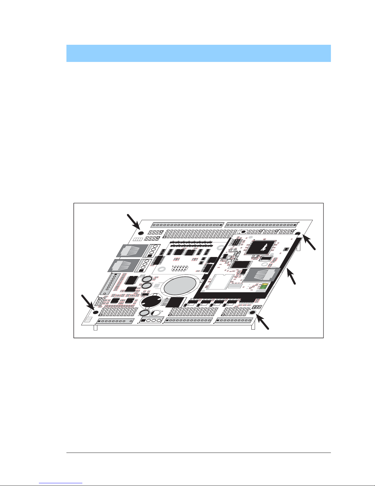
Position the BL2600 as shown below in Figure 2. Attach the four standoffs supplied with
the Tool Kit in the holes at the corners as shown.
Figure 2. Attach Standoffs to BL2600 Board
The standoffs facilitate handling the BL2600 during development, and protect the bottom
of the printed circuit board against scratches or short circuits while you are working with
the BL2600.
J15
J
1
6
AIN0
AIN1
AIN2
AIN3
JP6
420 mA
AV0 AV1 AV2 AV3 AI0 AI1 AI2 AI3 AGND
GND HOUT0 +HK1 GND HOUT2 +HK3 GND
+HK0 GND HOUT1 +HK2 GND HOUT3
TXC TXF TXE 485 GND
GND RXC RXF RXE 485+
J17
GND HOUT0 +HK1 GND HOUT2 +HK3 GND
+HK0 GND HOUT1 +HK2 GND HOUT3
TXC TXF TXE 485
AIN1 AIN3 AIN5 AIN7 AGND AV1 AV3 AI1 AI3 AGND
AIN0 AIN2 AIN4 AIN6 AGND AV0 AV2 AI0 AI2 AGND
J11
20
19
R43
JP6
R
4
4
R
3
9
R
38
R20
R
3
3
R
3
4
U13
R
2
2
R21
R17
C
1
8
C
1
9
U12
R15
C13
R16
C10
R10
U11
J8
R14 R
13 C
11
AIN0 A
IN
1 A
IN
2 A
IN
3 AIN
4 A
IN
5 A
IN
6 A
IN
7 AG
N
D
C
12 R12 R
11
U
1
0
BT1
C
2
6
C27
D1
U15
C25
J12
J13
C22
R
5
5
R
4
2
C23
C
2
4
R
4
1
R
4
0
R35
R36
R
3
7
U14
R26
R28
R30
R19
R29
R32
R
3
1
R
5
6
R
5
7
L1
R27R25
R23
R24
C20
C
2
1
R18
C
1
6
1
2
25
26
RXE
J14
Q19
D3
Q17D2Q18
RXC
D4
Q20
C34
RXF
485+
C35 C36 C37
JP7
485 TERM.
RESISTOR
C30
R58
R59
R60
U18
C32
C33
R
C
M
2
U17
C
3
1
R
9
U16
R8
J
1
0
R7
GND/EGND
RP5
RP6
U2
C
4
R
5
C
5
R6
C
6
U4
JA
RCM1
RCM3000 ETHERNET CORE MODULE
U
3
RP17 RP18
34
33
16
15
1
2
1
2
15
16
33
34
C1
U1
R
P
3
R
P
4
G
N
D
+
K
D
C
IN
+
5
V
J
P
3
,
J
P
4
A
N
D
J
P
4
JP1 AND JP2
G
N
D
+
K
D
C
IN
+
5
V
J4 RABBITNET 1
J6 RABBITNET 0
J7
C14
C17
C
1
5
C78
J9
C9
U9
RP16
C8
U8
R
4
R
3
RP15
RP14
RP12
R
P
1
3
R
P
1
1
R
1
R
2
C
7
U6
U7
U5
R
P
8R
P
7
R
P
9
R
P
1
0
C2
Q9
Q10
J5
Q12
Q15Q14 Q16
Q11
Q13
C3
Q1 Q2 Q3 Q4 Q5 Q6 Q7 Q8
JP2
JP1
J
1
J
2
GND DIN28 DIN24 DIN20 DIN16 GND DIO12 DIO08 DIO04 DIO00
DIN30 DIN26 DIN22 DIN18 +K DIO14 DIO10 DIO06 DIO02 GND
DIN31 DIN27 DIN23 DIN19 +K DIO15 DIO11 DIO07 DIO03 GND
GND DIN29 DIN25 DIN21 DIN17 GND DIO13 DIO09 DIO05 DIO01
GND DIO14 DIO12 DIO10 DIO08 DIO06 DIO04 DIO02 DIO00 GND
+K DIO15 DIO13 DIO11 DIO09 DIO07 DIO05 DIO03 DIO01 GND
GND DIN30 DIN28 DIN26 DIN24 GND DIN22 DIN20 DIN18 DIN16
DIN31 DIN29 DIN27 DIN25 +K DIN23 DIN21 DIN19 DIN17 GND
DIO 0007 PULLS
DIO 0815 PULLS
1
2
39
40
SW1
J
3
1
2
DCIN DCIN GND GND
R111
R
1
1
2
RESET
RP2
R
P
1
JP3
DIN 1619 PULLS
JP4
DIN 2023 PULLS
DIN 2431 PULLS
JP5
R84
C28
1
2
D
S
1
U1
U6
R28
R
38
R41
C5
C3
C9C
8
C
12
C
17
C
23
C
30
C18
C
29
C
35
C
33
R29
R37
R39
R40
R
42
Y3
C42R35
R
31
R27
R25
DS1
R67R
70
J4
C79
Y4
C
83
C86
GND
R75
R
74
R71
DS3
DS2
R63 R64
C71
C
72
C68
C64
C67
L2
U8
R49R
48
C62
R
51
C
61
R
44
R
47
C59
C
49
C57
L1
R69
R
72
R73
C
75
C
74
R58
C53
C47
C
48
C45C44C
43
J
P
5
C31
J
P
3
J
P
4
C28
C
27
C37C
36
C
32
R
24
R22
C
19
R23
C24
R20
C
20
R19
C16C
15
R17
R18
R7
R9
R1
R8
C
1
R10
R14
C
4
SP
D
LNK
AC
T
J3
U5
U4
D1
Q1
C
39
RP1
RabbitCore
Module
Page 10
6 Wolf (BL2600)
2.2 BL2600 Connections
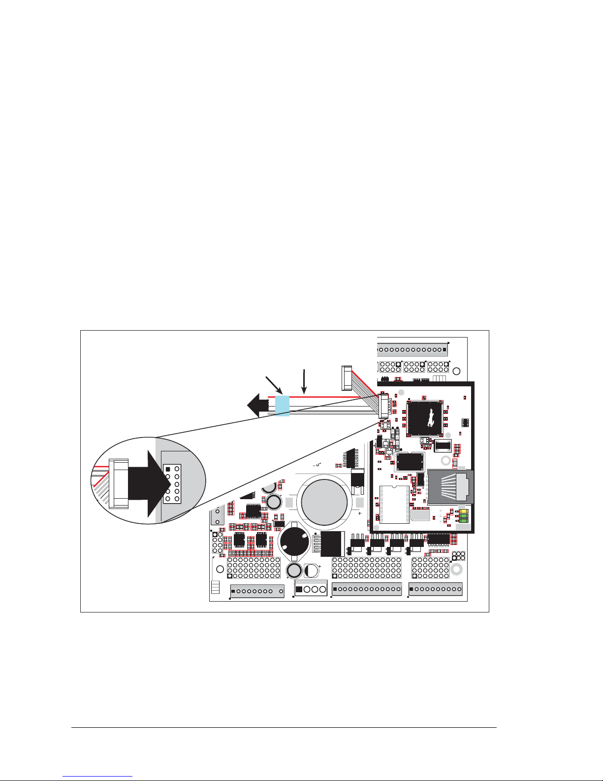
1. Connect the programming cable to download programs from your PC and to program
and debug the BL2600.
NOTE: Use only the programming cable that has a blue shrink wrap around the RS-232
level converter (Z-World part number 101-0542). If you are using a BL2610, which is
based on the RCM3000, you will need the programming cable that has a red shrink
wrap around the RS-232 level converter (Z-World part number 101-0513). Other
Z-World programming cables might not be voltage-compatible or their connector sizes
may be different.
Connect the 10-pin PROG connector of the programming cable to header J1 on the
BL2600’s RabbitCore module (header J3 for the BL2610 RabbitCore module). Ensure
that the colored edge lines up with pin 1 as shown. (Do n o t use t h e DIAG connector, which
is used for monitoring only.) Connect the other end of the programming cable to a COM
port on your PC. Make a note of the port to which you connect the cable, as Dynamic C
will need to have this parameter configured. Note that COM1 on the PC is the default
COM port used by Dynamic C.
Figure 3. Programming Cable Connections
NOTE: Some PCs now come equipped only with a USB port. It may be possible to use
an RS-232/USB converter (Z-World Part No. 540-0070) with the programming cables
mentioned above.
J15
J16
AIN0
AIN1
AIN2
AIN3
JP6
420 mA
AV0 AV1 AV2 AV3 AI0 AI1 AI2 AI3 AGND
GND HOUT0 +HK1 GND HOUT2 +HK3 GND
+HK0 GND HOUT1 +HK2 GND HOUT3
TXC TXF TXE 485 GND
GND RXC RXF RXE 485+
J17
GND HOUT0 +HK1 GND HOUT2 +HK3 GND
+HK0 GND HOUT1 +HK2 GND HOUT3
TXC TXF TXE 485
AIN1 AIN3 AIN5 AIN7 AGND AV1 AV3 AI1 AI3 AGND
AIN0 AIN2 AIN4 AIN6 AGND AV0 AV2 AI0 AI2 AGND
J11
20
19
R43
JP6
R44
R39
R38
R20
R33
R34
U13
R22
R21
R17
C18
C19
U12
R15
C13
R16
C10
R10
U11
J8
R14 R13 C11
AIN0 AIN1 AIN2 AIN3 AIN4 AIN5 AIN6 AIN7 AGND
C12 R12 R11
U10
BT1
C26
C27
D1
U15
C25
J12
J13
C22
R55
R42
C23
C24
R41
R40
R35
R36
R37
U14
R26
R28
R30
R19
R29
R32
R31
R56
R57
L1
R27R25
R23
R24
C20
C21
R18
C16
1
2
25
26
RXE
J14
Q19
D3
Q17D2Q18
RXC
D4
Q20
C34
RXF
485+
C35 C36 C37
JP7
485 TERM.
RESISTOR
C30
R58
R59
R60
U18
C32
C33
RCM2
U17
C31
R9
U16
R8
J10
R7
GND/EGND
RP5
RP6
U2
C4
R5
C5
R6
C6
U4
JA
RCM1
RCM3000 ETHERNET CORE MODULE
U3
RP17 RP18
34
33
16
15
1
2
1
2
15
16
33
34
C1
U1
RP3
RP4
GND
+K
DCIN
+5V
JP3,
JP4
AND
JP4
JP1 AND JP2
GND
+K
DCIN
+5V
J4 RABBITNET 1
J6 RABBITNET 0
J7
C14
C17
C15
C78
J9
C9
U9
RP16
C8
U8
R4
R3
RP15
RP14
RP12
RP13
RP11
R1
R2
C7
U6
U7
U5
RP8
RP7
RP9
RP10
C2
Q9
Q10
J5
Q12
Q15Q14 Q16
Q11
Q13
C3
Q1 Q2 Q3 Q4 Q5 Q6 Q7 Q8
JP2
JP1
J1
J2
GND DIN28 DIN24 DIN20 DIN16 GND DIO12 DIO08 DIO04 DIO00
DIN30 DIN26 DIN22 DIN18 +K DIO14 DIO10 DIO06 DIO02 GND
DIN31 DIN27 DIN23 DIN19 +K DIO15 DIO11 DIO07 DIO03 GND
GND DIN29 DIN25 DIN21 DIN17 GND DIO13 DIO09 DIO05 DIO01
GND DIO14 DIO12 DIO10 DIO08 DIO06 DIO04 DIO02 DIO00 GND
+K DIO15 DIO13 DIO11 DIO09 DIO07 DIO05 DIO03 DIO01 GND
GND DIN30 DIN28 DIN26 DIN24 GND DIN22 DIN20 DIN18 DIN16
DIN31 DIN29 DIN27 DIN25 +K DIN23 DIN21 DIN19 DIN17 GND
DIO 0007 PULLS
DIO 0815 PULLS
1
2
39
40
SW1
J3
1
2
DCIN DCIN GND GND
R111
R112
RESET
RP2
RP1
JP3
DIN 1619 PULLS
JP4
DIN 2023 PULLS
DIN 2431 PULLS
JP5
R84
C28
1
2
DS1
U1
U6
R28
R38
R41
C5
C3
C9
C8
C12
C17
C23
C30
C18
C29
C35
C33
R29
R37
R39
R40
R42
Y3
C42R35
R31
R27
R25
DS1
R67
R70
J4
C79
Y4
C83
C86
GND
R75
R74
R71
DS3
DS2
R63 R64
C71
C72
C68
C64
C67
L2
U8
R49
R48
C62
R51
C61
R44
R47
C59
C49
C57
L1
R69
R72
R73
C75
C74
R58
C53
C47
C48
C45
C44
C43
JP5
C31
JP3
JP4
C28
C27
C37
C36
C32
R24
R22
C19
R23
C24
R20
C20
R19
C16
C15
R17
R18
R7
R9
R1
R8
C1
R10
R14
C4
SPD LNK ACT
J3
U5
U4
D1
Q1
C39
RP1
DIAG
PROG
Colored edge
To
PC COM port
Programming Cable
PROG
J1
Blue
shrink wrap
Page 11
User’s Manual 7
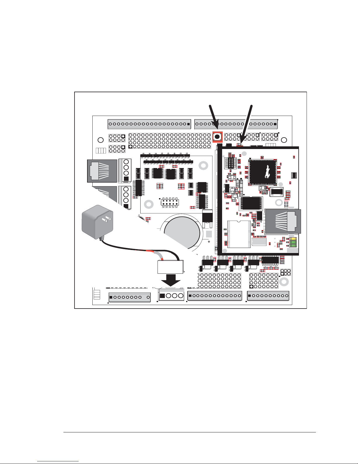
2. Connect the power supply to header J12 on the BL2600 as shown in Figure 4. You can
use the crimps and the friction-lock connector included in the Tool Kit to connect the
leads from the power supply, then match the friction lock tab on the friction-lock connector to the back of header J12 on the BL2600 as shown. The friction-lock connector
will only fit one way.
Figure 4. Power Supply Connections
3. Apply power.
Plug in the power supply. The power LED will light up when the BL2600 is powered up
correctly.
CAUTION: Unplug the power supply while you make or otherwis e work wit h the co nnection s
to the headers. This will prot ect your BL2 600 fr om ina dver tent shor ts or power spikes.
2.2.1 Hardware Reset
A hardware reset is done by unplugging the power supply, then plugging it back in, or by
pressing the RESET button located just above the RabbitCore module.
J15
J16
AIN0
AIN1
AIN2
AIN3
JP6
420 mA
AV0 AV1 AV2 AV3 AI0 AI1 AI2 AI3 AGND
GND HOUT0 +HK1 GND HOUT2 +HK3 GND
+HK0 GND HOUT1 +HK2 GND HOUT3
TXC TXF TXE 485 GND
GND RXC RXF RXE 485+
J17
GND HOUT0 +HK1 GND HOUT2 +HK3 GND
+HK0 GND HOUT1 +HK2 GND HOUT3
TXC TXF TXE 485
AIN1 AIN3 AIN5 AIN7 AGND AV1 AV3 AI1 AI3 AGND
AIN0 AIN2 AIN4 AIN6 AGND AV0 AV2 AI0 AI2 AGND
J11
20
19
R43
JP6
R44
R39
R38
R20
R33
R34
U13
R22
R21
R17
C18
C19
U12
R15
C13
R16
C10
R10
U11
J8
R14 R13 C11
AIN0 AIN1 AIN2 AIN3 AIN4 AIN5 AIN6 AIN7 AGND
C12 R12 R11
U10
BT1
C26
C27
D1
U15
C25
J12
J13
C22
R55
R42
C23
C24
R41
R40
R35
R36
R37
U14
R26
R28
R30
R19
R29
R32
R31
R56
R57
L1
R27R25
R23
R24
C20
C21
R18
C16
1
2
25
26
RXE
J14
Q19
D3
Q17D2Q18
RXC
D4
Q20
C34
RXF
485+
C35 C36 C37
JP7
485 TERM.
RESISTOR
C30
R58
R59
R60
U18
C32
C33
RCM2
U17
C31
R9
U16
R8
J10
R7
GND/EGND
RP5
RP6
U2
C4
R5
C5
R6
C6
U4
JA
RCM1
RCM3000 ETHERNET CORE MODULE
U3
RP17 RP18
34
33
16
15
1
2
1
2
15
16
33
34
C1
U1
RP3
RP4
GND
+K
DCIN
+5V
JP3,
JP4
AND
JP4
JP1 AND JP2
GND
+K
DCIN
+5V
J4 RABBITNET 1
J6 RABBITNET 0
J7
C14
C17
C15
C78
J9
C9
U9
RP16
C8
U8
R4
R3
RP15
RP14
RP12
RP13
RP11
R1
R2
C7
U6
U7
U5
RP8
RP7
RP9
RP10
C2
Q9
Q10
J5
Q12
Q15Q14 Q16
Q11
Q13
C3
Q1 Q2 Q3 Q4 Q5 Q6 Q7 Q8
JP2
JP1
J1
J2
GND DIN28 DIN24 DIN20 DIN16 GND DIO12 DIO08 DIO04 DIO00
DIN30 DIN26 DIN22 DIN18 +K DIO14 DIO10 DIO06 DIO02 GND
DIN31 DIN27 DIN23 DIN19 +K DIO15 DIO11 DIO07 DIO03 GND
GND DIN29 DIN25 DIN21 DIN17 GND DIO13 DIO09 DIO05 DIO01
GND DIO14 DIO12 DIO10 DIO08 DIO06 DIO04 DIO02 DIO00 GND
+K DIO15 DIO13 DIO11 DIO09 DIO07 DIO05 DIO03 DIO01 GND
GND DIN30 DIN28 DIN26 DIN24 GND DIN22 DIN20 DIN18 DIN16
DIN31 DIN29 DIN27 DIN25 +K DIN23 DIN21 DIN19 DIN17 GND
DIO 0007 PULLS
DIO 0815 PULLS
1
2
39
40
SW1
J3
1
2
DCIN DCIN GND GND
R111
R112
RESET
RP2
RP1
JP3
DIN 1619 PULLS
JP4
DIN 2023 PULLS
DIN 2431 PULLS
JP5
R84
C28
1
2
DS1
Power LED
U1
U6
R28
R38
R41
C5
C3
C9
C8
C12
C17
C23
C30
C18
C29
C35
C33
R29
R37
R39
R40
R42
Y3
C42R35
R31
R27
R25
DS1
R67
R70
J4
C79
Y4
C83
C86
GND
R75
R74
R71
DS3
DS2
R63 R64
C71
C72
C68
C64
C67
L2
U8
R49
R48
C62
R51
C61
R44
R47
C59
C49
C57
L1
R69
R72
R73
C75
C74
R58
C53
C47
C48
C45
C44
C43
JP5
C31
JP3
JP4
C28
C27
C37
C36
C32
R24
R22
C19
R23
C24
R20
C20
R19
C16
C15
R17
R18
R7
R9
R1
R8
C1
R10
R14
C4
SPD LNK ACT
J3
U5
U4
D1
Q1
C39
RP1
J12
RESET
+
Page 12

8 Wolf (BL2600)
2.3 Installing Dynamic C
If you have not yet installed Dynamic C version 8.51 (or a later version), do so now by
inserting the Dynamic C CD from the BL2600 T ool Kit in your PC’s CD-ROM drive. The
CD will auto-install unless you have disabled auto-install on your PC.
If the CD does not auto-install, click
Start > Run from the Windows Start button and
browse for the Dynamic C setup.exe file on your CD drive. Click OK to begin the
installation once you have selected the
setup.exe file.
The online documentation is installed along with Dynamic C, and an icon for the documentation menu is placed on the workstation’s desktop. Double-click this icon to reach the
menu. If the icon is missing, create a new desktop icon that points to
default.htm in the
docs folder, found in the Dynamic C installation folder.
The latest versions of all documents are always available for free, unregistered download
from our Web sites as well.
The Dynamic C User’s Manual provides detailed instructions for the installation of
Dynamic C and any future upgrades.
NOTE: If you have an earlier version of Dynamic C already installed, the default instal-
lation of the la te r ver sion wi ll b e in a different fold er, and a sep arate icon will appear on
your desktop.
Once your installation is complete, you will have up to three icons on your PC desktop.
One icon is for Dynamic C, one opens the documentation menu, and the third is for the
Rabbit Field Utility, a tool used to download precompiled software to a target system.
If you have purchased any of the optional Dynamic C modules, install them after installing
Dynamic C. The modules may be installed in any order. You must install the modules in
the same directory where Dynamic C was installed.
Page 13

User’s Manual 9
2.4 St arting Dynamic C
Once the BL2600 is connected to your PC and to a power s ource, s ta rt Dyn ami c C by double-
clicking on the Dynamic C icon or by double-clicking on dcrabXXXX.exe in the Dynami c C
root directory, where XXXX are version-specific characters.
Dynamic C defaults to using the serial port on your PC that you specified during installation. If the port setting is correct, Dynamic C should detect the BL2600 and go through a
sequence of steps to cold-boot the BL2600 and to compile the BIOS. (Some versions of
Dynamic C will not do the initial BIOS compile and load until the firs t time you compile a
program.)
If you receive the message
No Rabbit Processor Detected, the programming
cable may be connected to the wrong COM port, a connection may be faulty, or the target
system may not be powered up. First, check both ends of the programming cable to ensure
that it is firmly plugged into the PC and the programming port.
If there are no faults with the hardware, select a different COM port within Dynamic C.
From the
Options menu, select Communications. Select another COM port from the list,
then click OK. Press <Ctrl-Y> to force Dynamic C to recompile the BIOS. If Dynamic C
still reports it is unable to locate the target system, repeat the above steps until you locate the
active COM port. You should receive a Bios compiled successfully message
once this step is completed successfully.
If Dynamic C appears to compile the BIOS successfully, but you then receive a communication error message when you compile and load a sample program, it is possible that your
PC cannot handle the higher program-loading baud rate. Try changing the maximum
download rate to a slower baud rate as follows.
• Locate the Serial Options dialog in the Dynamic C Options > Communications
menu. Select a slower Max download baud rate.
If a program compiles and loads, but then loses target communication before you can
begin debugging, it is possible that your PC cannot handle the default debugging baud
rate. Try lowering the debugging baud rate as follows.
• Locate the
Serial Options dialog in the Dynamic C Options > Communications
menu. Choose a lower debug baud rate.
Page 14

10 Wolf (BL2600)
2.5 PONG.C
You are now ready to test your set-up by running a sample program.
Find the file
PONG.C, which is in the Dynamic C SAMPLES folder. To run the program,
open it with the
File menu (if it is not still open), compile it using the Compile menu, and
then run it by selecting Run in the Run menu. The STDIO window will open and will display a small square bouncing around in a box.
This program shows that the CPU is working. The sample program described in
Section 5.2.3, “Run the PINGME.C Demo,” tests the TCP/IP portion of the board.
2.6 Where Do I Go From Here?
NOTE: If you purchased your BL2600 through a distributor or Z-World partner, contact
the distributor or Z-World partner first for technical support.
If there are any problems at this point:
• Check the Z-W orld Technical Bulletin Board at www .zworld.com/support/bb/.
• Use the Technical Support e-mail form at www.zworld.com/support/.
If the sample program ran fine, you are now ready to go on to explore other BL2600 features and develop your own applications.
Chapter 3, “Subsystems,” provides a description of the BL2600’s features, Chapter 4,
“Software,” describes the Dynamic C software libraries and introduces some sample programs, and Chapter 5, “Using the TCP/IP Features,” explains the TCP/IP features.
2.6.1 Real-Time Clock
If you plan to use the real-time clock functionality in your application, you will need to set
the real-time clock. You may set the real-time clock using the SETRTCKB.C sample program from the Dynamic C SAMPLES\RTCLOCK folder. The RTC_TEST.C sample program in the Dynamic C SAMPLES\RTCLOCK folder provides additional examples of how
to read and set the real-time clock
Page 15
User’s Manual 11
3. SUBSYSTEMS
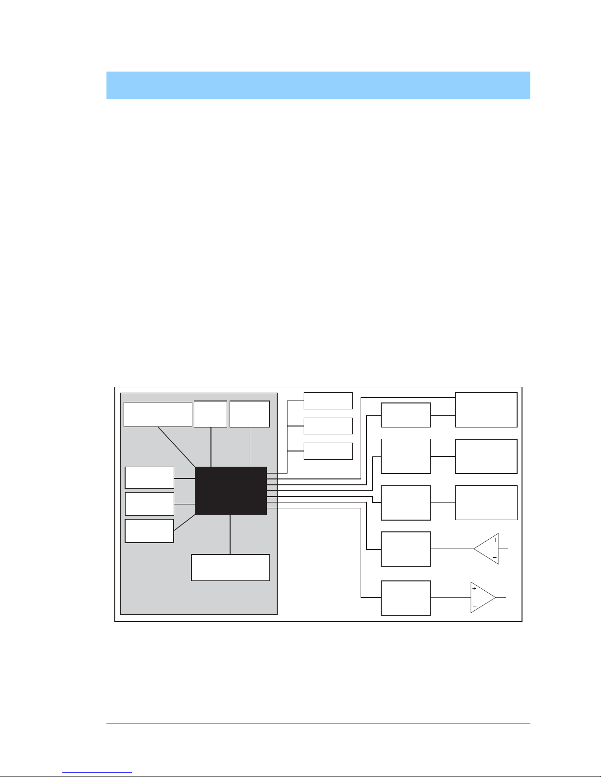
Chapter 3 describes the principal subsystems for the BL2600.
•Digital I/O
•Serial Communication
•A/D Converter Inputs
•D/A Converter Outputs
•Analog Reference Voltage Circuit
•Memory
Figure 5 shows these Rabbit-based subsystems designed into the BL2600.
Figure 5. BL2600 Subsystems
SRAM
32 kHz
osc
RabbitCore Module
RABBIT
3000
Battery-Backup
Circuit
Ethernet
Program
Flash
Serial
Flash
22.1 MHz
osc
RS-232
RS-485
Data
Register
Data
Register
A/D
Converter
D/A
Converter
High-Current
Outputs
RabbitNet
Digital
Inputs
Configurable
I/O
Data
Register
Page 16
12 Wolf (BL2600)
3.1 BL2600 Pinouts
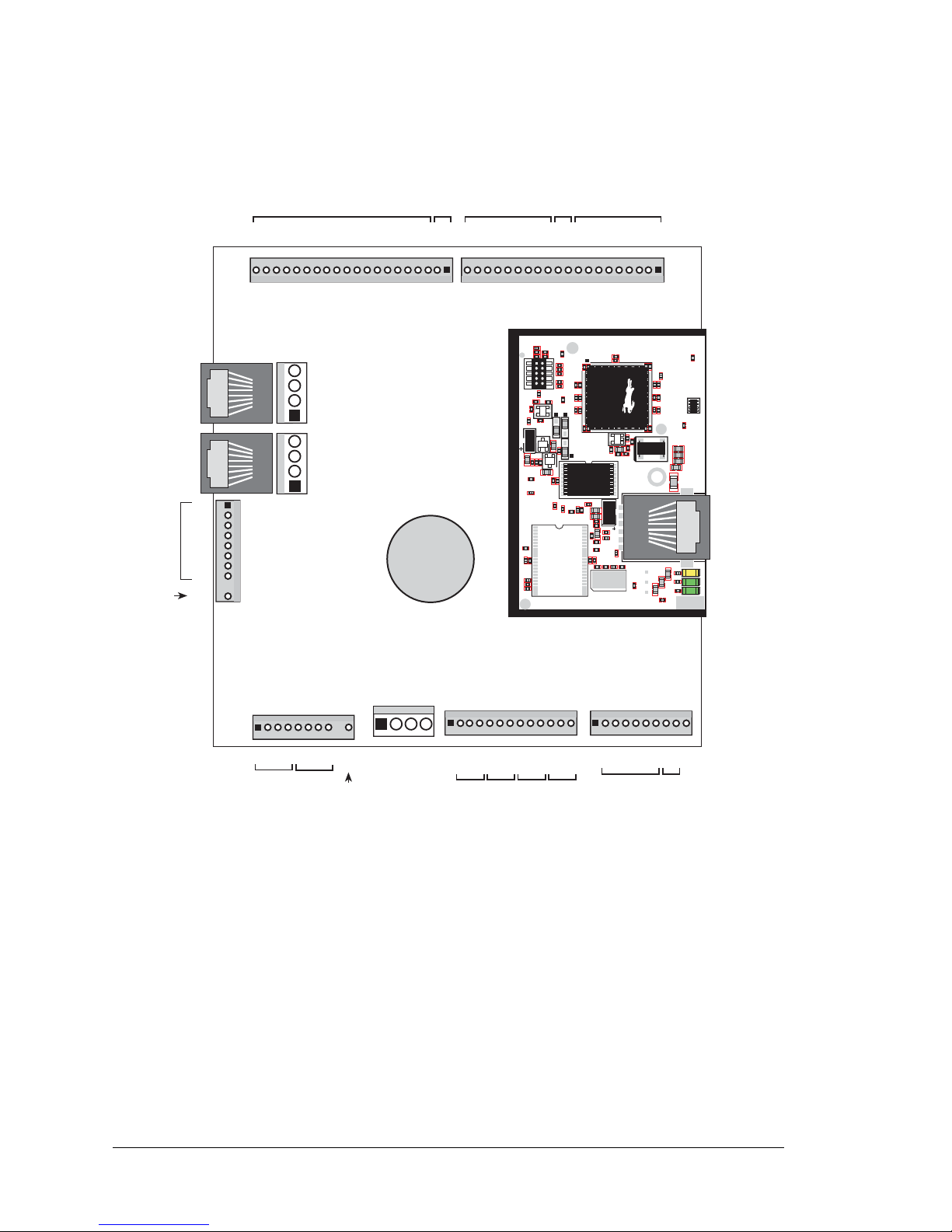
The BL2600 pinouts are shown in Figure 6(a) and Figure 6(b).
Figure 6(a). BL2600 Pinouts (friction-lock connectors)
3.1.1 Connector Options
Standard BL2600 models are equipped with two 1 × 20 friction-lock connector terminals
(J1 and J2), two polarized 1 × 9 friction-lock connector terminals (J8 and J15), one 1 × 13
friction-lock connector terminal (J16), and one 1 × 10 friction-lock connector terminal
(J17); all of these friction-lock connector terminals have a 0.1" pitch.
The RJ-45 jacks at J4 and J6 labeled RabbitNet are serial I/O expansion ports for use with
RabbitNet peripheral expansion boards. The
RabbitNet jacks do not support Ethernet con-
nections. Be careful to make your Ethernet connection to the jack labeled
Ethernet in the
above diagram (note that BL2610 models do not have an Ethernet port).
J15
DCIN
DCIN
GND
GND
J16
AV0 AV1 AV2 AV3 AI0 AI1 AI2 AI3 AGND
GND HOUT0 +HK1 GND HOUT2 +HK3 GND
+HK0 GND HOUT1 +HK2 GND HOUT3
TXC TXF TXE 485 GND
GND RXC RXF RXE 485+
J17
J12
J5
J1 J2
U1
U6
R28
R38
R41
C5
C3
C9
C8
C12
C17
C23
C30
C18
C29
C35
C33
R29
R37
R39
R40
R42
Y3
C42R35
R31
R27
R25
DS1
R67
R70
J4
C79
Y4
C83
C86
GND
R75
R74
R71
DS3
DS2
R63 R64
C71
C72
C68
C64
C67
L2
U8
R49
R48
C62
R51
C61
R44
R47
C59
C49
C57
L1
R69
R72
R73
C75
C74
R58
C53
C47
C48
C45
C44
C43
JP5
C31
JP3
JP4
C28
C27
C37
C36
C32
R24
R22
C19
R23
C24
R20
C20
R19
C16
C15
R17
R18
R7
R9
R1
R8
C1
R10
R14
C4
SPD LNK ACT
J3
U5
U4
D1
Q1
C39
RP1
J8
High-Current
Digital Outputs
Analog
Ground
Analog
Outputs
Battery
AIN0
AIN1
AIN2
AIN3
AIN4
AIN5
AIN6
AIN7
AGND
Analog
Inputs
RabbitNet
J6
J4
J7
GND
GND
DIO00
DIO01
DIO02
DIO03
DIO04
DIO05
DIO06
DIO07
DIO08
DIO09
DIO10
DIO11
DIO12
DIO13
DIO14
DIO15
GND
+K
GND
DIN16
DIN17
DIN18
DIN19
DIN20
DIN21
DIN22
DIN23
GND+KDIN24
DIN25
DIN26
DIN27
DIN28
DIN29
DIN30
DIN31
GND
Configurable I/O
Digital Inputs
Digital Inputs
Analog
Ground
Ethernet
AV0
AV1
AV2
AV3
AI0
AI1
AI2
AI3
AGND
Power
Supply
GND
+HK0
HOUT0
GND
+HK1
HOUT1
GND
+HK2
HOUT2
GND
+HK3
HOUT3
GND
VOLTAGE CURRENT
0 1 2 3
GND
TxC
RxC
TxF
RxF
TxE
RxE
485
485+
GND
RS-232
RS-485
+K
+K
Page 17
User’s Manual 13
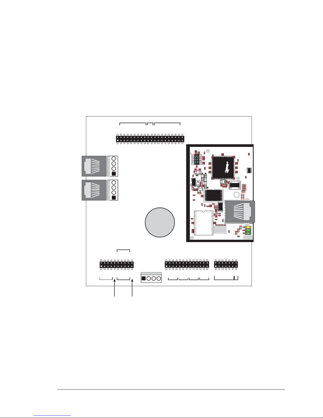
Two 4-pin 0.156" friction-lock connector terminals at J5 and J7 are installed to supply
power (DCIN and +5 V) to the RabbitNet peripheral expansion boards. The 4-pin 0.156"
friction-lock connector terminal at J12 is for the main power supply connections.
The BL2600 also has 2 × 20, 2 × 13, 2 × 10, and 2 × 7 IDC sockets with a pitch of 0.1" in
addition to the friction-lock connectors. Corresponding headers or ribbon cables may be
plugged into these sockets from either the top or the bottom. A top view of the pinouts for
these sockets is shown in Figure 6(b).
Figure 6(b). BL2600 Pinouts (IDC sockets)
NOTE: Remember that the pinouts will mirror those shown above when the y ar e viewed
from the other side of the board.
DCIN
DCIN
GND
GND
J13
J12
J5
J3
J11
J14
U1
U6
R28
R38
R41
C5
C3
C9
C8
C12
C17
C23
C30
C18
C29
C35
C33
R29
R37
R39
R40
R42
Y3
C42R35
R31
R27
R25
DS1
R67
R70
J4
C79
Y4
C83
C86
GND
R75
R74
R71
DS3
DS2
R63 R64
C71
C72
C68
C64
C67
L2
U8
R49
R48
C62
R51
C61
R44
R47
C59
C49
C57
L1
R69
R72
R73
C75
C74
R58
C53
C47
C48
C45
C44
C43
JP5
C31
JP3
JP4
C28
C27
C37
C36
C32
R24
R22
C19
R23
C24
R20
C20
R19
C16
C15
R17
R18
R7
R9
R1
R8
C1
R10
R14
C4
SPD LNK ACT
J3
U5
U4
D1
Q1
C39
RP1
High-Current
Digital Outputs
Analog
Ground
Analog
Outputs
Battery
Analog
Inputs
RabbitNet
J6
J4
J7
GND
DIO01
DIO03
DIO05
DIO07
DIO09
DIO11
DIO13
DIO15
GND+KDIN17
DIN19
DIN21
DIN23
DIN25
DIN27
DIN29
DIN31
GND
Configurable
I/O
Digital Inputs
Ethernet
AIN0
AIN2
AIN4
AIN6
AGND
AV0
AV2
AI0
AI2
AGND
Power
Supply
GND
+HK0
HOUT0
GND
+HK1
HOUT1
GND
+HK2
HOUT2
GND
+HK3
HOUT3
GND
VOLTAGE
CURRENT
0 1 2 3
TxC
GND
TxF
GND
TxE
GND
485
RS-232
RS-485
+K
GND
DIO00
DIO02
DIO04
DIO06
DIO08
DIO10
DIO12
DIO14
GND
+K
DIN16
DIN18
DIN20
DIN22
DIN24
DIN26
DIN28
DIN30
GND
AIN1
AIN3
AIN5
AIN7
AGND
AV1
AV3
AI1
AI3
AGND
RxC
GND
RxF
GND
RxE
GND
485+
Analog
Ground
TOP VIEW
GND
+HK0
HOUT0
GND
+HK1
HOUT1
GND
+HK2
HOUT2
GND
+HK3
HOUT3
GND
Page 18
14 Wolf (BL2600)
3.2 Digital I/O
3.2.1 Digital Inputs
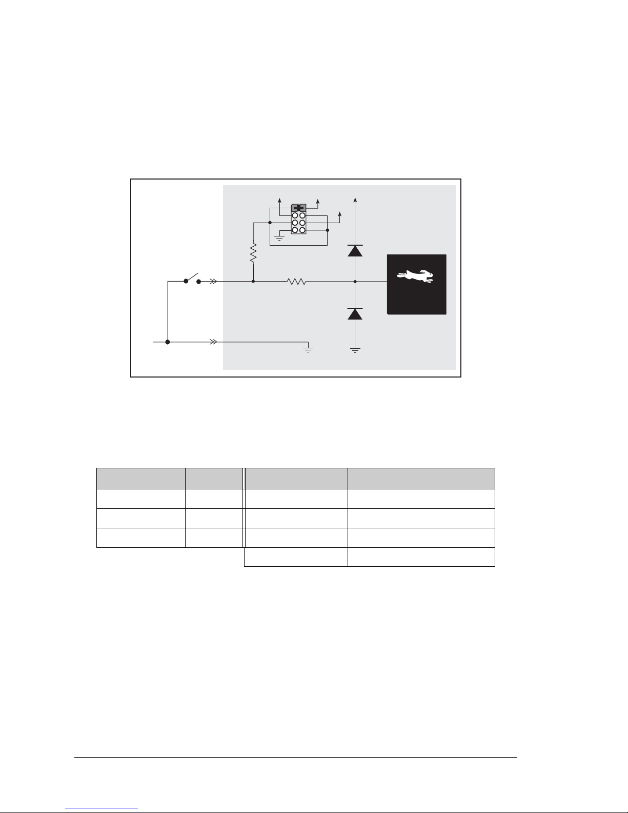
The BL2600 has 16 digital inputs, DIN16–DIN31, each of which is protected over a range
of –36 V to +36 V. The inputs are factory-configured to be pulled up to +5 V, but they can
also be pulled up to +K or DCIN, or pulled down to 0 V i n banks by changing a j umper as
shown in Figure 7.
Figure 7. BL2600 Digital Inputs DIN16–DIN31 [Pulled Up—Factory Default]
Table 2 lists the banks of digital inputs and summarizes the jumper settings.
When you use the software digIn function call to read the digital inputs, DIN16–DIN31
are considered to be digital input channels 16–31.
Table 2. Banks of BL2600 Digital Inputs
Digital Inputs Header Pins Jumpered Pulled Up/Pulled Down
DIN16–DIN19 JP3 1–2 Inputs pulled up to +5 V
DIN20–DIN23 JP4 3–4 Inputs pulled up to DCIN
DIN24–DIN31 JP5 5–6 Inputs pulled up to +K
7–8 Inputs pulled down to GND
100 kW
27 kW
GND
+K
DCIN
+5 V
Rabbit 3000
®
Microprocessor
+3.3 V
Page 19
User’s Manual 15
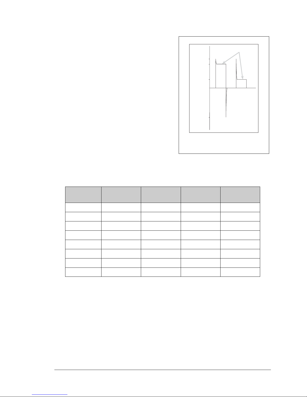
The actual switching threshold is approximately
1.40 V. Anything below this value is a logic 0,
and anything above is a logic 1. The digital inputs
are each fully protected over a range of -36 V to
+36 V, and can handle short spikes of ±40 V.
NOTE: If the inputs are pulled up to +K or
to DCIN, the voltage range over which
the digital inputs are protected changes
to +K (or DCIN) – 36 V to +36 V.
Individual DIN16–DIN23 channels may be used
for interrupts, input capture, as quadrature decoders, or as PWM outputs.
The use of these channels for interrupts, input
capture, and as quadrature decoders is described
in the Rabbit 3000 Microp ro cess or U s er’s Manual,
and is illustrated through sample programs in the
Dynamic C SAMPLES\RABBIT3000 folder. Table 3 lists these alternate uses.
3.2.2 PWM Outputs
Digital inputs DIN20–DIN23 can be used as PWM output channels by setting the jumper
on header JP4 across pins 7–8 to pull the digital inputs to ground. Once the PWM driver
sets up a given PWM channel, the corresponding digital input channel is no longer available for use as a digital input. T he output vo ltage swing will be 0 to 2. 5 V, which is su itable
for interfacing only to CMOS-level inputs. Since the output impedance is approximately
27 kΩ, the input impedance of the circuit the PWM output is connected to should be at
least 10 times as high.
The sample program
PWM.C in the IO subdirectory in SAMPLES\BL2600 shows how to
set up and use the PWM outputs.
Table 3. Alternate Uses for BL2600 Channels DIN16–DIN23
Channel Interrupt Input Capture
Quadrature
Decoder
PWM Outputs
DIN16 ×
DIN17 ×
DIN18 ×
DIN19 ××
DIN20 ××
DIN21 ×××
DIN22 ××
DIN23 ×××
Figure 8. BL2600 Digital Input
Protected Range
+40 V
+36 V
+3.3 V
40 V
Normal Switching
Levels
Spikes
Digital Input Voltage
Spikes
Spikes
Page 20
16 Wolf (BL2600)
3.2.3 High-Current Digital Outputs
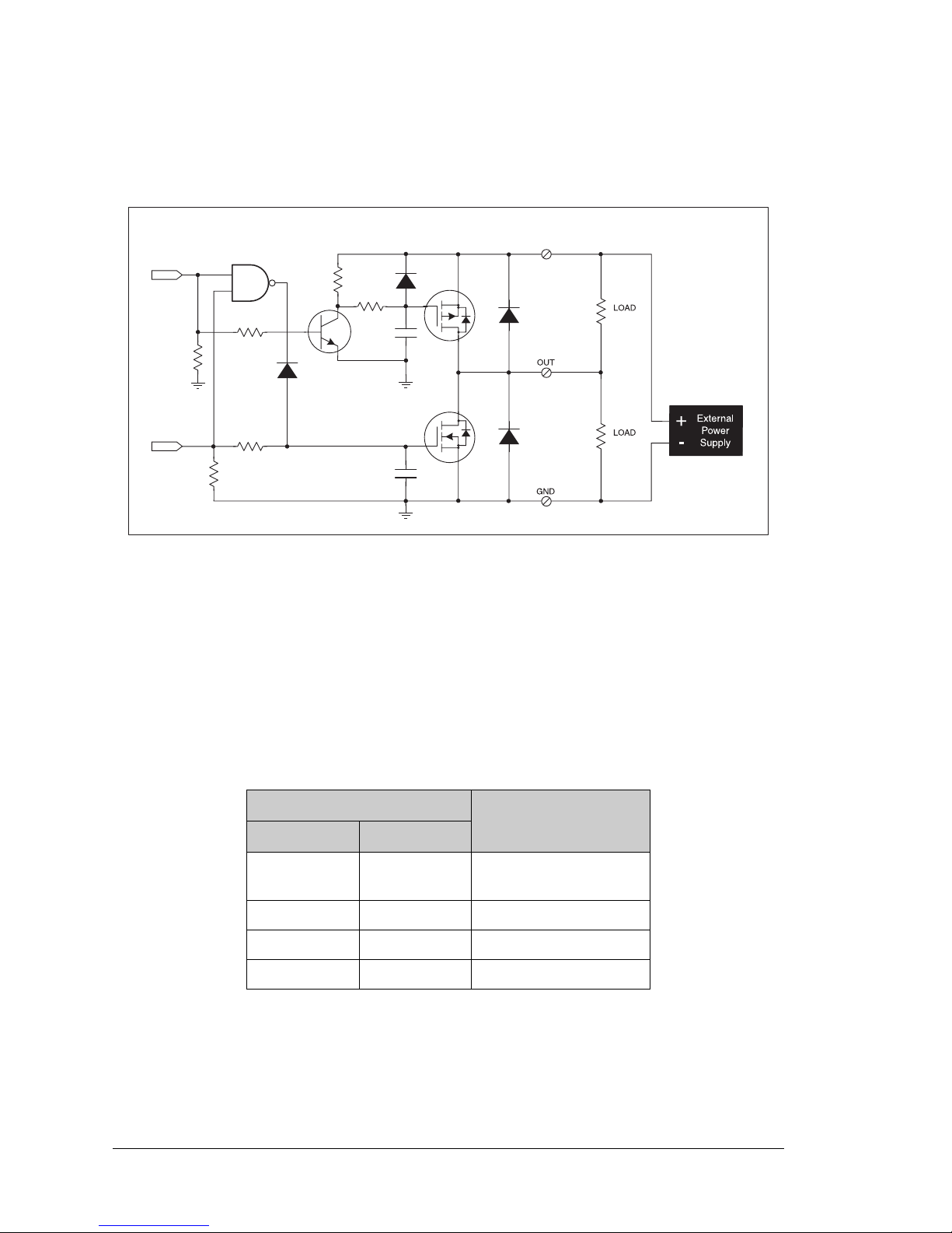
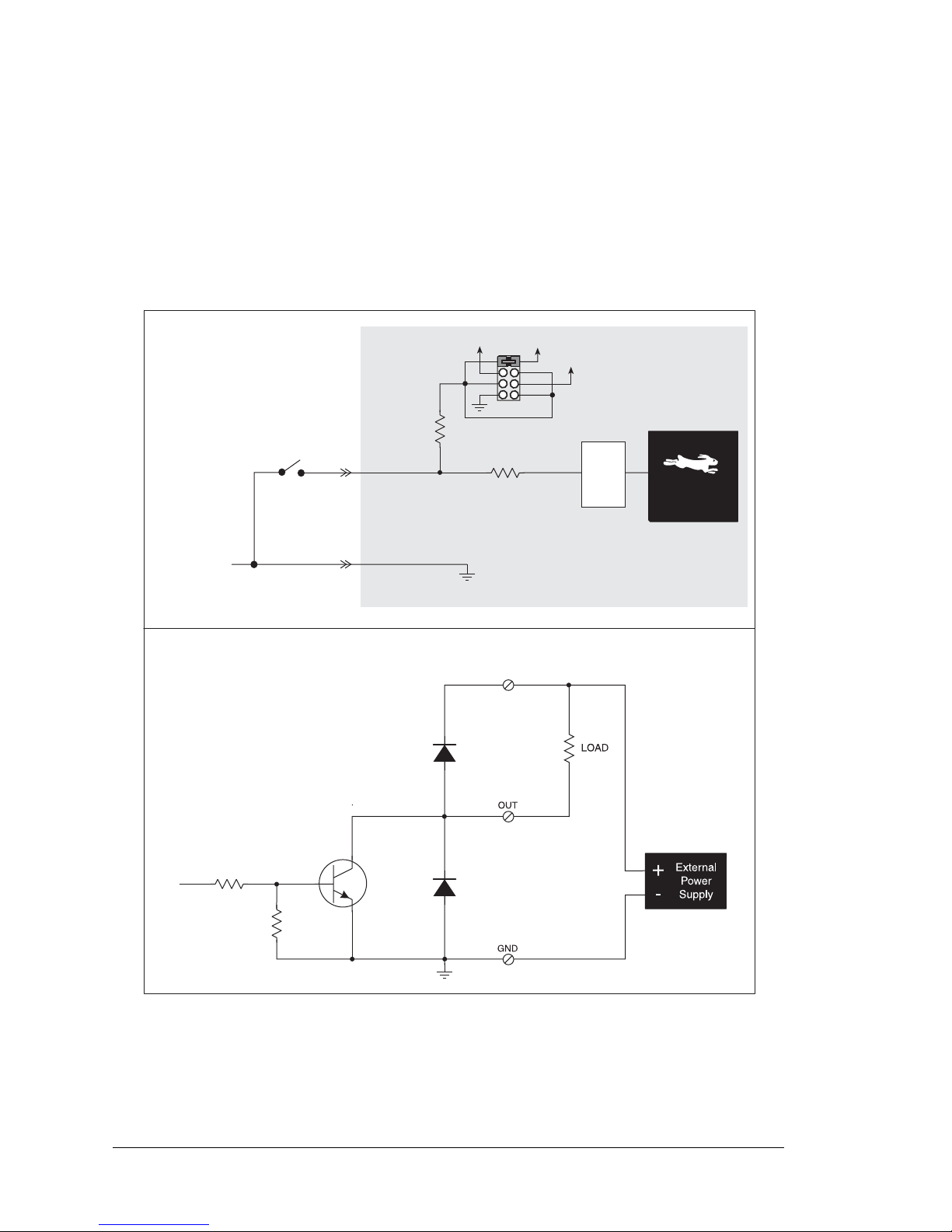
The BL2600 has four high-current digital outputs, HOUT0–HOUT3, which can each sink
or source up to 2 A. Figure 9 shows a wiring diagram for using the digital outputs in either
a sinking or a souring configuration.
Figure 9. BL2600 High-Current Digital Outputs
All the digital outputs sink and source actively. They can be used as high-side drivers, lowside drivers, or as an H-bridge driver. When the BL2600 is first powered up or reset, all
the outputs are disabled, that is, at a high-impedance tristate, until the digHoutConfig
software function call is made. The digHoutConfig call sets the initial state of each
high-current output according to the configuration specified by the user, and enables the
digital outputs to their initial status.
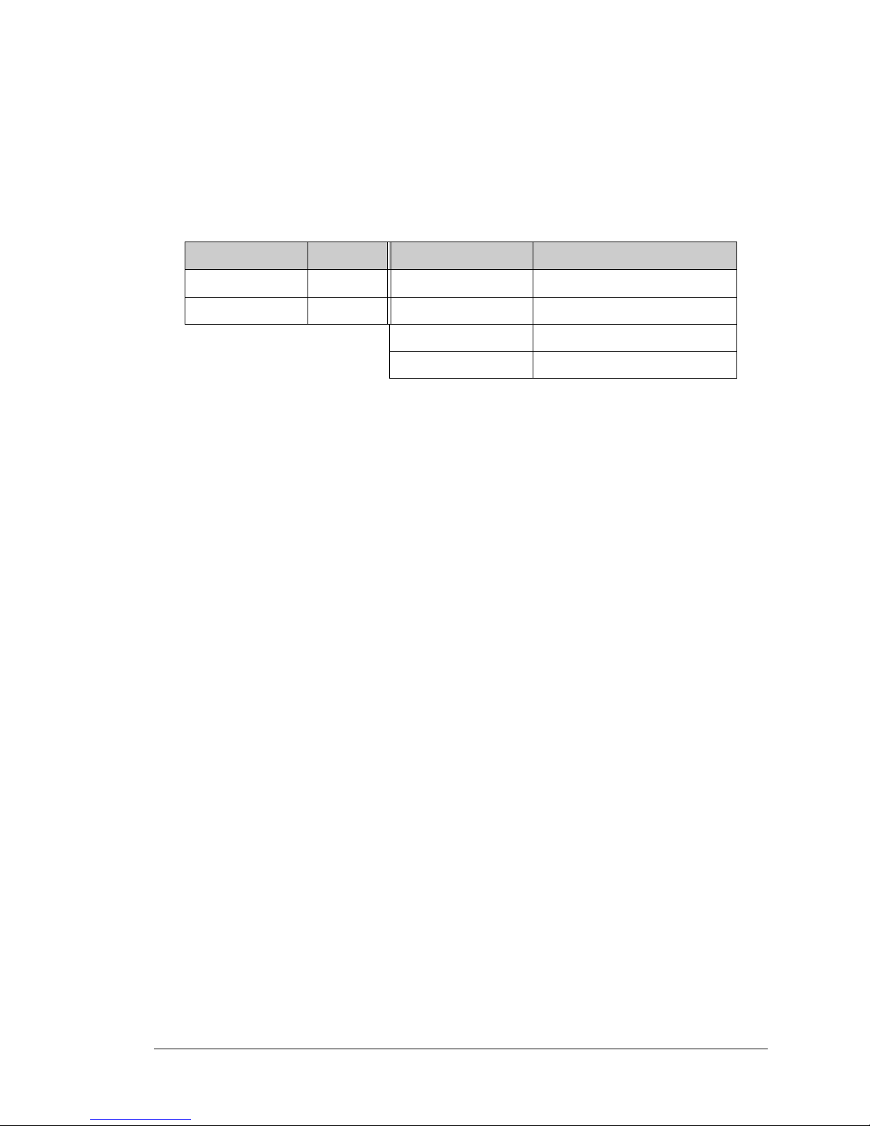
Table 4. BL2600 High-Curre nt Outputs Logic States
U3 Output
High-Current Output
A B
High High
Prohibited
(defaults to sourcing)
High Low Sourcing
Low High Sinking
Low Low High-impedance (tristate)
+HKx
100 kW
330 W
10 kW
10 kW
27 kW
1 nF
100 kW
1 nF
MMBT4401
B
A
(in sinking
mode)
(in sourcing
mode)
Page 21
User’s Manual 17
Each high-current output has its own +K supply. When wiring the high-current outputs,
keep the distance to the power supply as short as possible.
CAUTION: If you are using a BL2600 with the ID C hea der con nec tors, beware that
an individual IDC header pin can only handle up to 1 A. Since the same high-current
outputs are avail able on opposit e pair s o f IDC head er conne ctors , you can sti ll us e the
2 A sinking or sourcing capability of the BL2600 by wiring all your connections,
including the ground, in parallel to the opposite pairs (see Figure 10 for an example).
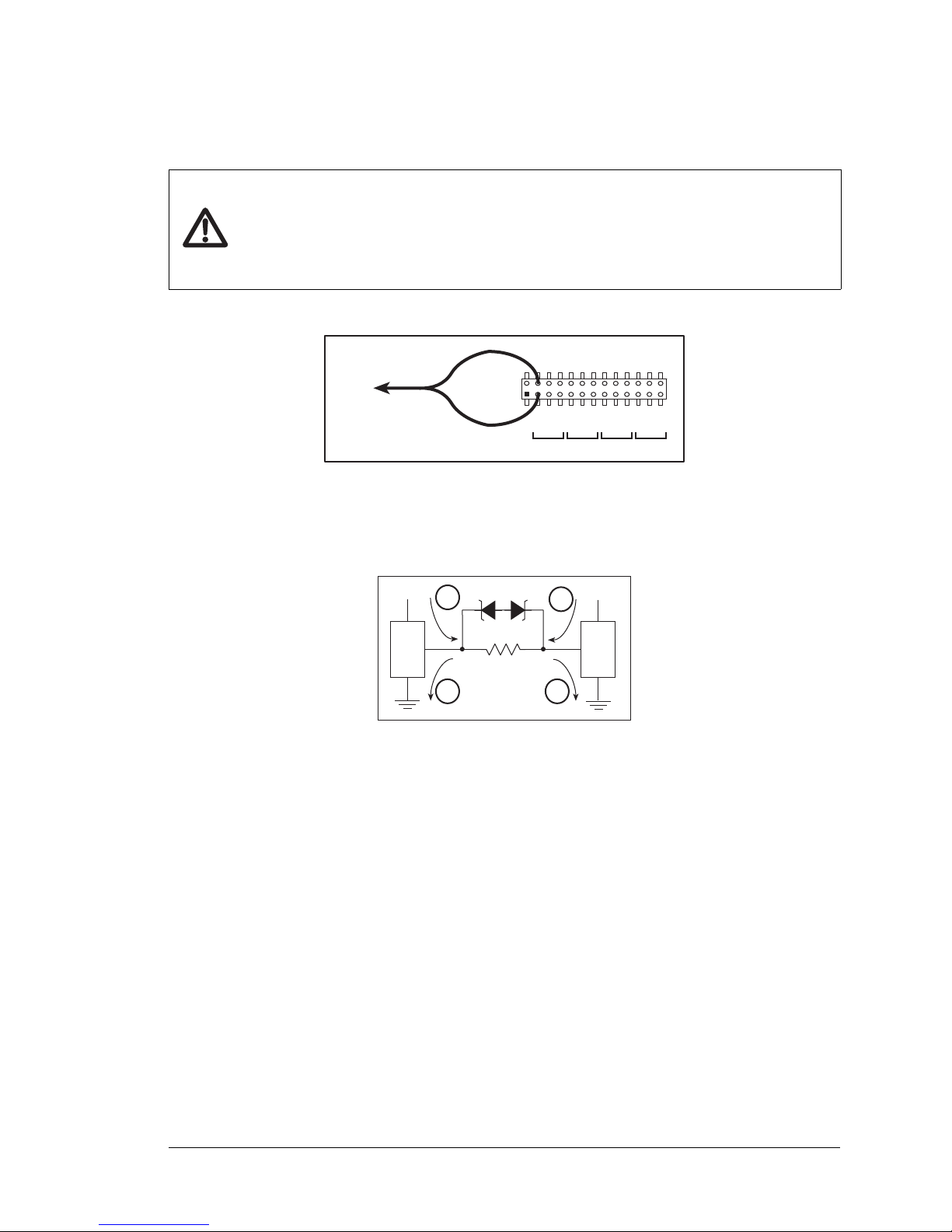
Figure 10. Example of Wiring HK0 In Parallel on IDC Header
For the H bridge, which is shown in Figure 11, Ka and Kb should be the same.
Figure 11. H Bridge
J13
GND
+HK0
HOUT0
GND
+HK1
HOUT1
GND
+HK2
HOUT2
GND
+HK3
HOUT3
GND
0 1 2 3
GND
+HK0
HOUT0
GND
+HK1
HOUT1
GND
+HK2
HOUT2
GND
+HK3
HOUT3
GND
+HK0
+Ka
+Kb
LOAD
A
A
B
B
Page 22
18 Wolf (BL2600)
3.2.4 Configurable I/O
The BL2600 has 16 configurable I/O that may be configured individually in software as
either digital inputs or as sinking digital outputs. By default, a configurable I/O channel is
a digital input, but may be set as a sinking digital output by using the digOutConfig
function call. The inputs are factory-configured to be pulled up to +5 V, but they can also
be pulled up to +K or DCIN, or pulled down to 0 V in banks by changing a jumper as
shown in Figure 12.
Figure 12. BL2600 Configurable I/O DIO00–DIIO15 [Inputs Pulled Up—Factory Default]
100 kW
27 kW
GND
+K
DCIN
+5 V
+K
SINKING OUTPUT
27 kW
220 W
DIGITAL INPUT
Rabbit 3000
®
Microprocessor
Buffer
Page 23
User’s Manual 19
When you use the software digIn function call to read the configurable I/O, DIO00–
DIO15 are considered to be digital input channels 00–15. Note that the digIn function
call can also read these channels if they are set to be sinking digital outputs.
Table 2 lists the banks of digital inputs and summarizes the jumper settings.
As for the nonconfigurable digital inputs, the actual switching threshold is approximately
1.40 V. Anything below this value is a logic 0, and anything above is a logic 1. The digital
inputs are each fully protected over a range of -36 V to +36 V, and can handle short spikes
of ±40 V.
NOTE: If the inputs are pulled up to +K or to DCIN, the voltage range over which
the digital inputs are protected changes to +K (or DCIN) – 36 V to +36 V.
When set as a sinking digital output, a configurable I/O channel can sink up to 200 mA at
up to 40 V. When you use the software digOutConfig function call to set the configurable I/O, DIO00–DIO15 are considered to be digital output channels 00–15. The output
can be set up either as a sinking output or it can be put in a high-impedance tristate.
Table 5. Banks of BL2600 Digital Inputs
Digital Inputs Header Pins Jumpered Pulled Up/Pulled Down
DIO00–DIO07 JP1 1–2 Inputs pulled up to +5 V
DIO08–DIO15 JP2 3–4 Inputs pulled up to DCIN
5–6 Inputs pulled up to +K
7–8 Inputs pulled down to GND
Page 24
20 Wolf (BL2600)
3.3 Serial Communication
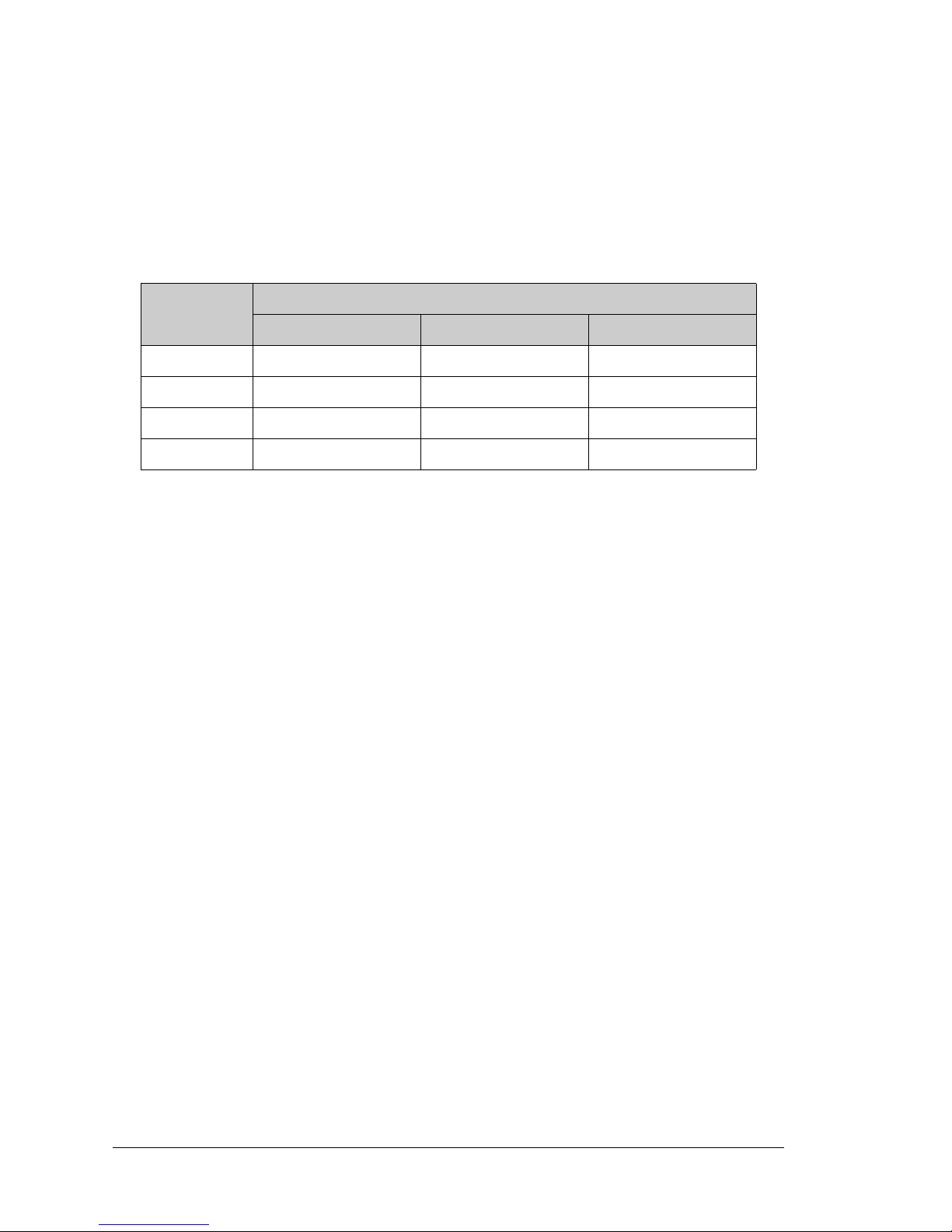
The BL2600 has three serial communication ports, which can be configured as one RS-232
serial channel (with RTS/CTS) and one RS-232 (3-wire) channel or one RS-485 channel, or
as three RS-232 (3-wire) channels, or as two RS-232 (3-wire) channels and one RS-485
channel by using the serMode software function call. Table 6 summarizes the options.
The BL2600 also has one CMOS serial channel that serves as the programming port.
All four serial ports operate in an asynchronous mode. An asynchronous port can handle 7
or 8 data bits. A 9th bit address scheme, where an additional bit is sent to mark the first
byte of a message, is also supported. Serial Port A, the programming port, can be operated
alternately in the clocked serial mode. In this mode, a clock line synchronously clocks the
data in or out. Either of the two communicating devices can supply the clock. The BL2600
boards typically use all four ports in the asynchronous serial mode. Serial Ports C and F
are used for RS-232 communication, and Serial Port E is used for RS-232 or RS-485 communication. The BL2600 uses a 22.12 MHz resonator, which is doubled to 44.2 MHz. At
this frequency, the BL2600 supports standard asynchronous baud rates up to a maximum
of 5.525 Mbps.
3.3.1 RS-232
The BL2600 RS-232 serial communication is supported by an RS-232 transceiver. This
transceiver provides the voltage output, slew rate, and input voltage immunity required to
meet the RS-232 serial communication protocol. Basically, the chip translates the Rabbit
3000’s CMOS signals to RS-232 signal levels. Note that the polarity is reversed in an
RS-232 circuit so that a +3.3 V output becomes approximately -10 V and 0 V is output as
+10 V. The RS-232 transceiver also provides the proper line loading for reliable communication.
RS-232 can be used effectively at the BL2600’s maximum baud rate for distances of up to
15 m.
3.3.2 RS-485
The BL2600 can be set for one RS-485 serial channel, which is connected to the Rabbit
3000 Serial Port E through an RS-485 transceiver. The half-duplex communication uses
the Rabbit 3000’s PE3 pin to control the transmit enable on the communication line.
Table 6. Serial Communication Configurations
Mode
Serial Port
C E F
0 RS-232, 3-wire RS-232, 3-wire RS-232, 3-wire
1 RS-232, 3-wire RS-485 RS-232, 3-wire
2 RS-232, 5-wire RS-232, 3-wire CTS/RTS
3 RS-232, 5-wire RS-485 CTS/RTS
Page 25
User’s Manual 21
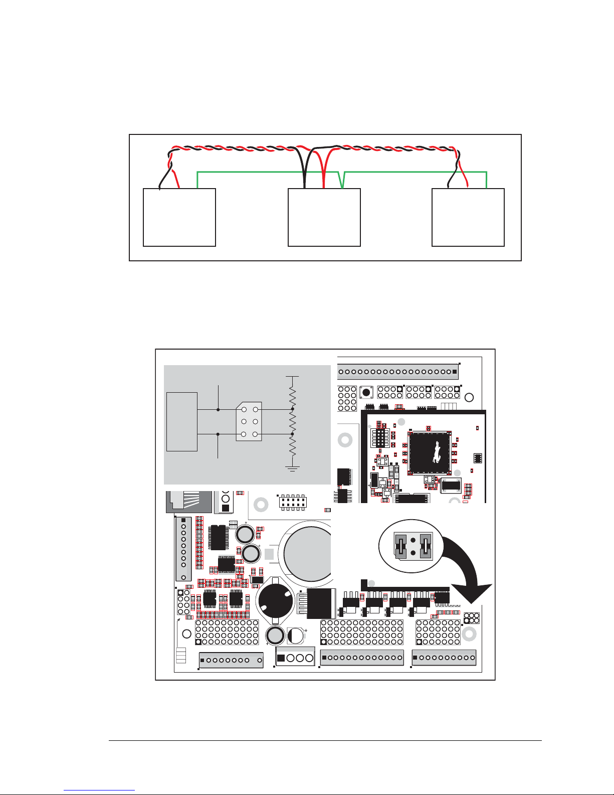
The BL2600 can be used in an RS-485 multidrop network. Connect the 485+ to 485+ and
485– to 485– using single twisted-pair wires (nonstranded, tinned) as shown in Figure 13.
Note that a common ground is recommended.
Figure 13. BL2600 Multidrop Network
The BL2600 comes with a 220 Ω termination resistor and two 681 Ω bias resistors installed
and enabled with jumpers across pins 1–2 and 5–6 on header JP7, as shown in Figure 14.
Figure 14. RS-485 Termination and Bias Resistors
RS-485
RS485+
GND
RS-485
RS485+
GND
RS-485
RS485+
GND
J15
J16
AIN0
AIN1
AIN2
AIN3
JP6
420 mA
AV0 AV1 AV2 AV3 AI0 AI1 AI2 AI3 AGND
GND HOUT0 +HK1 GND HOUT2 +HK3 GND
+HK0 GND HOUT1 +HK2 GND HOUT3
TXC TXF TXE 485 GND
GND RXC RXF RXE 485+
J17
GND HOUT0 +HK1 GND HOUT2 +HK3 GND
+HK0 GND HOUT1 +HK2 GND HOUT3
TXC TXF TXE 485
AIN1 AIN3 AIN5 AIN7 AGND AV1 AV3 AI1 AI3 AGND
AIN0 AIN2 AIN4 AIN6 AGND AV0 AV2 AI0 AI2 AGND
J11
20
19
R43
JP6
R44
R39
R38
R20
R33
R34
U13
R22
R21
R17
C18
C19
U12
R15
C13
R16
C10
R10
U11
J8
R14 R13 C11
AIN0 AIN1 AIN2 AIN3 AIN4 AIN5 AIN6 AIN7 AGND
C12 R12 R11
U10
BT1
C26
C27
D1
U15
C25
J12
J13
C22
R55
R42
C23
C24
R41
R40
R35
R36
R37
U14
R26
R28
R30
R19
R29
R32
R31
R56
R57
L1
R27R25
R23
R24
C20
C21
R18
C16
1
2
25
26
RXE
J14
Q19
D3
Q17D2Q18
RXC
D4
Q20
C34
RXF
485+
C35 C36 C37
JP7
485 TERM.
RESISTOR
C30
R58
R59
R60
U18
C32
C33
RCM2
U17
C31
R9
U16
R8
J10
R7
GND/EGND
RP5
RP6
U2
C4
R5
C5
R6
C6
U4
JA
RCM1
RCM3000 ETHERNET CORE MODULE
U3
RP17 RP18
34
33
16
15
1
2
1
2
15
16
33
34
C1
U1
RP3
RP4
GND
+K
DCIN
+5V
JP3,
JP4
AND
JP4
JP1 AND JP2
GND
+K
DCIN
+5V
J4 RABBITNET 1
J6 RABBITNET 0
J7
C14
C17
C15
C78
J9
C9
U9
RP16
C8
U8
R4
R3
RP15
RP14
RP12
RP13
RP11
R1
R2
C7
U6
U7
U5
RP8
RP7
RP9
RP10
C2
Q9
Q10
J5
Q12
Q15Q14 Q16
Q11
Q13
C3
Q1 Q2 Q3 Q4 Q5 Q6 Q7 Q8
JP2
JP1
J1
J2
GND DIN28 DIN24 DIN20 DIN16 GND DIO12 DIO08 DIO04 DIO00
DIN30 DIN26 DIN22 DIN18 +K DIO14 DIO10 DIO06 DIO02 GND
DIN31 DIN27 DIN23 DIN19 +K DIO15 DIO11 DIO07 DIO03 GND
GND DIN29 DIN25 DIN21 DIN17 GND DIO13 DIO09 DIO05 DIO01
GND DIO14 DIO12 DIO10 DIO08 DIO06 DIO04 DIO02 DIO00 GND
+K DIO15 DIO13 DIO11 DIO09 DIO07 DIO05 DIO03 DIO01 GND
GND DIN30 DIN28 DIN26 DIN24 GND DIN22 DIN20 DIN18 DIN16
DIN31 DIN29 DIN27 DIN25 +K DIN23 DIN21 DIN19 DIN17 GND
DIO 0007 PULLS
DIO 0815 PULLS
1
2
39
40
SW1
J3
1
2
DCIN DCIN GND GND
R111
R112
RESET
RP2
RP1
JP3
DIN 1619 PULLS
JP4
DIN 2023 PULLS
DIN 2431 PULLS
JP5
R84
C28
1
2
DS1
U1
U6
R28
R38
R41
C5
C3
C9
C8
C12
C17
C23
C30
C18
C29
C35
C33
R29
R37
R39
R40
R42
Y3
C42R35
R31
R27
R25
DS1
R67
R70
J4
C79
Y4
C83
C86
GND
R75
R74
R71
DS3
DS2
R63 R64
C71
C72
C68
C64
C67
L2
U8
R49
R48
C62
R51
C61
R44
R47
C59
C49
C57
L1
R69
R72
R73
C75
C74
R58
C53
C47
C48
C45
C44
C43
JP5
C31
JP3
JP4
C28
C27
C37
C36
C32
R24
R22
C19
R23
C24
R20
C20
R19
C16
C15
R17
R18
R7
R9
R1
R8
C1
R10
R14
C4
SPD LNK ACT
J3
U5
U4
D1
Q1
C39
RP1
JP7
4
3
2
1
R97
681 W
R98
220 W
R96
681 W
485+
485
6
7
termi-
nation
bias
bias
U17
JP7
2
1
6
5
6
5
Factory
Default
Page 26

22 Wolf (BL2600)
For best performance, the bias and termination resistors in a multidrop network should
only be enabled on both end nodes of the network. Disable the termination and bias resistors on any intervening BL2600 units in the network by removing both jumpers from
header JP6.
TIP: Save the jumpers for possible fut ure us e by “par king” t hem acr oss pin s 1–3 and 4 –6
of header JP7. Pins 3 and 4 are not otherwise connected to the BL2600.
3.3.3 Programming Port
The RabbitCore module on the BL2600 has a 10-pin programming header. The programming port uses the Rabbit 3000’s Serial Port A for communication, and is used for the following operations.
• Programming/debugging
• Cloning
The programming port is used to start the BL2600 in a mode where the BL2600 will
download a program from the port and then execute the program. The programming port
transmits information to and from a PC while a program is being debugged.
The Rabbit 3000 startup-mode pins (SMODE0, SMODE1) are presented to the programming port so that an externally connected device can force the BL2600 to start up in an
external bootstrap mode. The BL2600 can be reset from the programming port via the
/EXT_RSTIN line.
The Rabbit 3000 status pin is also presented to the programming port. The status pin is an
output that can be used to send a general digital signal.
NOTE: Refer to the Rabbit 3000 Microprocessor User’s Manual for more information
related to the bootstrap mode.
Page 27
User’s Manual 23
3.3.4 Ethernet Port
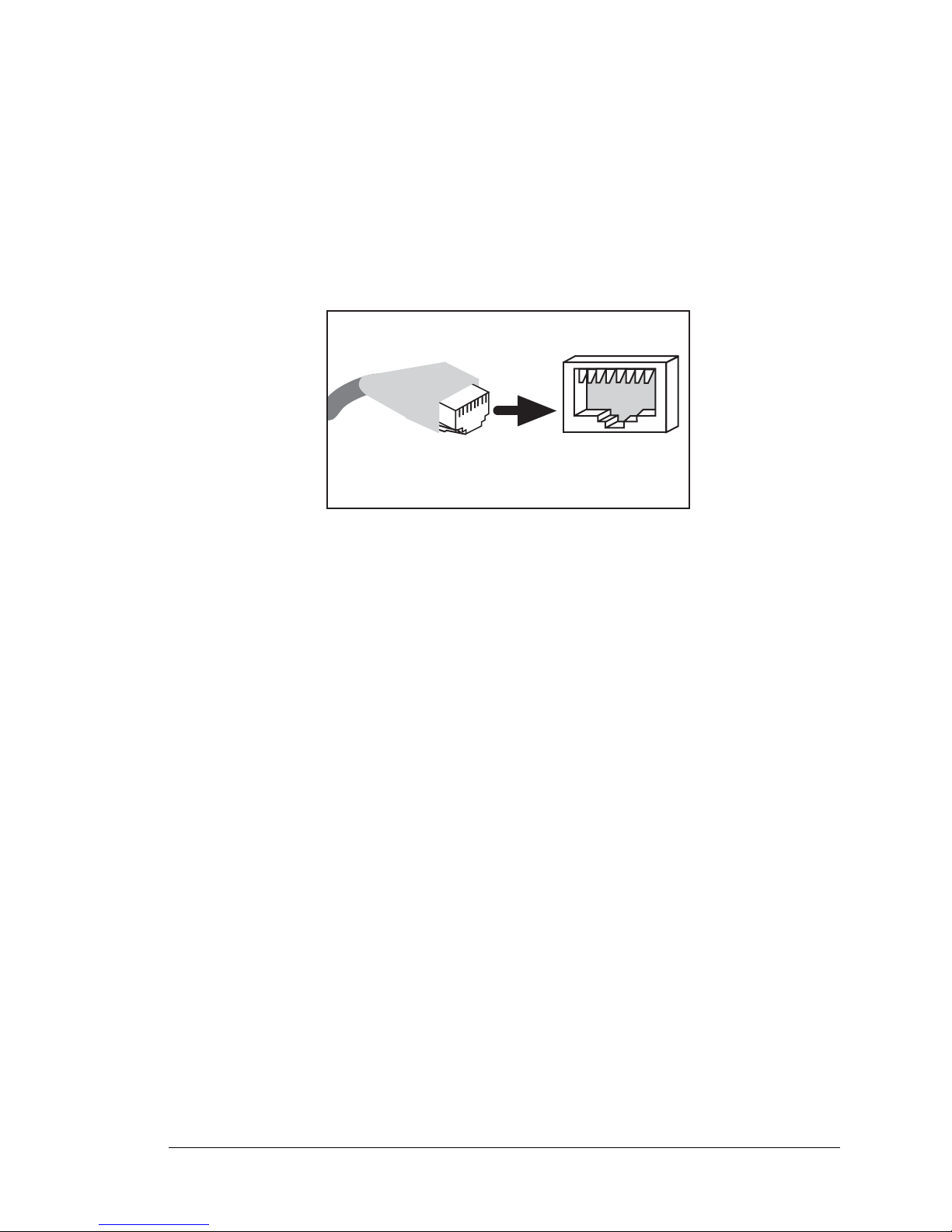
Figure 15 shows the pinout for the Ethernet port (J2 on the BL2600 module). Note that
there are two standards for numbering the pins on this connector—the convention used
here, and numbering in reverse to that shown. Regardless of the numbering convention
followed, the pin positions relative to the spring tab position (located at the bottom of the
RJ-45 jack in Figure 15) are always absolute, and the RJ-45 connector will work properly
with off-the-shelf Ethernet cables.
Figure 15. RJ-45 Ethernet Port Pinout
Two LEDs are placed next to the RJ-45 Ethernet jack, one to indicate an Ethernet link
(LNK) and one to indicate Ethernet activity (ACT).
The RJ-45 connector is shielded to minimize EMI effects to/from the Ethernet signals.
ETHERNET
RJ-45 Plug
1. E_Tx+
2. E_Tx
3. E_Rx+
6. E_Rx
1
8
RJ-45 Jack
Page 28
24 Wolf (BL2600)
3.4 A/D Converter Inputs
The single A/D converter chip used in the BL2600 has a resolution of 12 bits (11 bits for the
value and one bit for the polarity)
. The A/D converter chip has a programmable amplifier.
Each external input has circuitry that provides scaling and filtering. All 8 external inputs
are scaled and filtered to provide the user with an input impedance of 1 MΩ and a variety
of single-ended unipolar, singl e-ended bipolar, and differential bipolar ranges as shown in
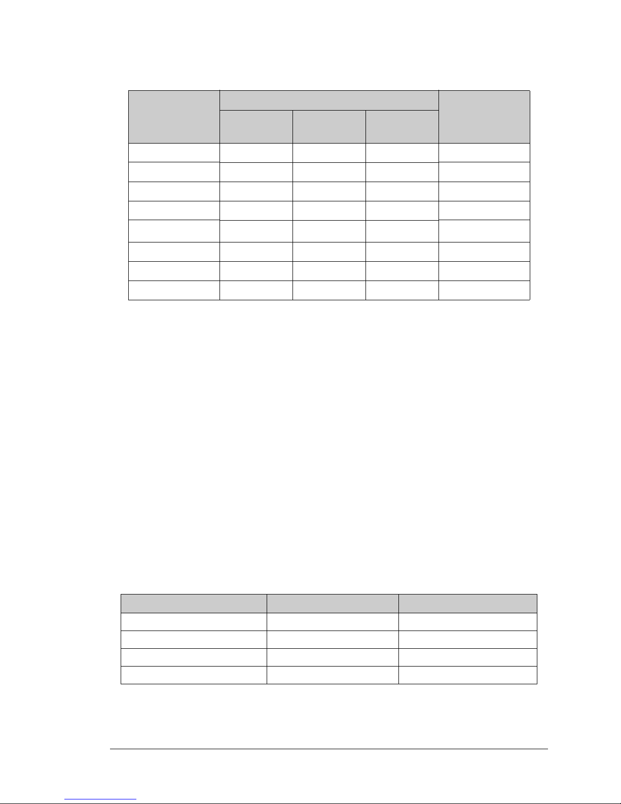
Table 7.
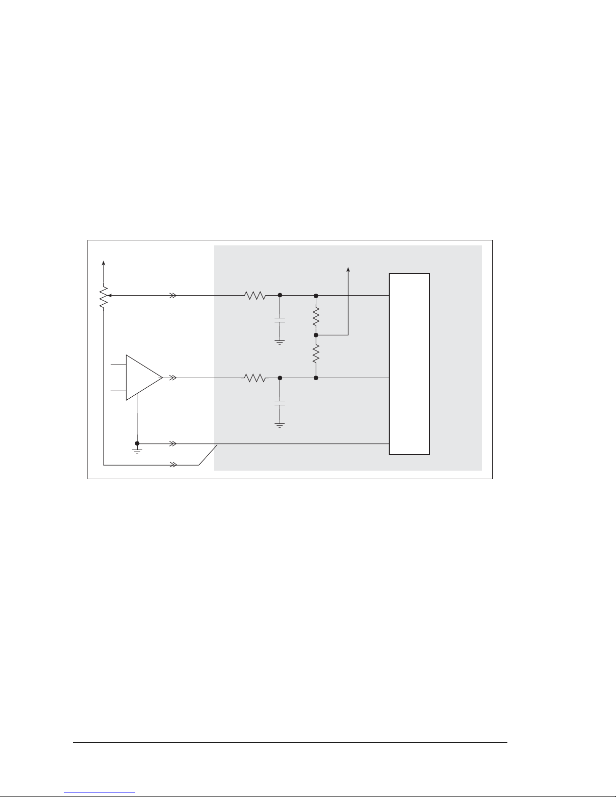
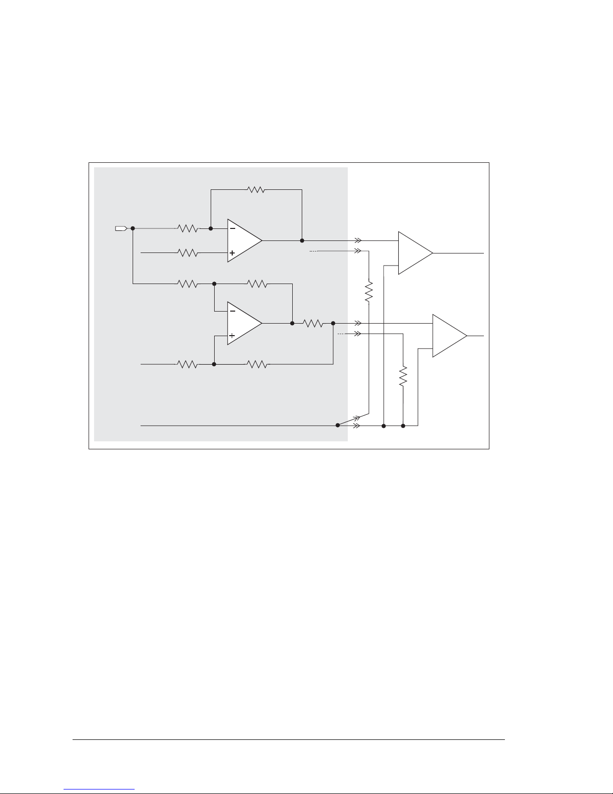
Figure 16 shows a pair of A/D converter input circuits. The resistors form an approx. 10:1
attenuator, and the capacitors filter noise pulses from the A/D converter inputs.
Figure 16. Buffered A/D Converter Inputs
The A/D converter chip can only accept positive voltages. By pairing the analog inputs and
setting the reference voltage from the D/A converter [0 V for single-ended unipolar or differential measurements, V = (voltage range) ÷ 9 for single-ended bipolar measurements],
single-ended unipolar, single-ended bipolar, differential bipolar, or current (4–20 mA on
channels 0–3 only) measurements are possible, and can be configured for each channel or
channel pair with the
opmode parameter in the anaInConfig software function call.
Adjacent A/D converter inputs are paired to make bipolar measurements. The default
setup is to measure only voltages for the ranges listed in Table 7.
ADC
1 MW
1 nF
AIN0
AGND
+ V
AIN1
1 nF
Ref. Voltage
from D/A Converter
105 kW
105 kW
Page 29
User’s Manual 25
When using channels AIN0–AIN3 for current measurements, remember to set the corresponding jumper(s) on header JP6.
The A/D converter inputs are factory-calibrated and the calibration constants are stored in a
separate EEPROM.
3.4.1 A/D Converter Calibration
To get the best results form the A/D converter, it is necessary to calibrate each mode (single-ended, differential, and current) for each of its gains. It is imperative that you calibrate
each of the A/D converter inputs in the same manner as they are to be used in the application. For example, if you will be performing floating differential measurements or differential measurements using a common analog ground, then calibrate the A/D converter in
the corresponding manner. The calibration table in software only holds calibration constants based on mode, channel, and gain.
Other factors affec ting the calibr ation must be taken
into account by calibrating using the same mode and gain setup as in the intended use.
Sample programs are provided to illustrate how to read and calibrate the various A/D
inputs for the three operating modes.
These sample programs are found in the
ADC subdirectory in SAMPLES\BL2600. See
Section 4.2.4 for more information on these sample programs and how to use them.
Table 7. A/D Converter Input Voltage Ranges
Amplifier
Gain
Voltage Range
mV per Tick
Single-Ended
Unipolar
Single-Ended
Bipolar
Differential
Bipolar
1 0–20 V ±10 V ± 20 V 10
2 0–10 V ±5 V ± 10 V 5
4 0–5 V ±2 .5 V ± 5 V 2.5
5 0–4 V ±2 V ± 4 V 2.0
8
*
0–2.5 V ±1.25 V ± 2.5 V 1.25
10 0–2 V ±1 V ± 2 V 1.0
16 0–1.25 V ±0.625 V ± 1.25 V 0.625
20 0–1 V ±0.5 V ± 1 V 0.500
* 4–20 mA operation is available with an amplifier gain of 8
Mode Read Calibrate
Single-Ended, unipolar AD_RD_SE_UNIPOLAR.C ADC_CAL_SE_UNIPOLAR.C
Single-Ended, bipolar AD_RD_SE_BIPOLAR.C ADC_CAL_SE_BIPOLAR.C
Differential, bipolar AD_RD_DIFF.C ADC_CAL_DIFF.C
Milli-Amp AD_RD_MA.C ADC_CAL_MA.C
Page 30
26 Wolf (BL2600)
3.5 D/A Converter Outputs
The four D/A converter outputs are buffered and scaled to provide an output from 0 V to
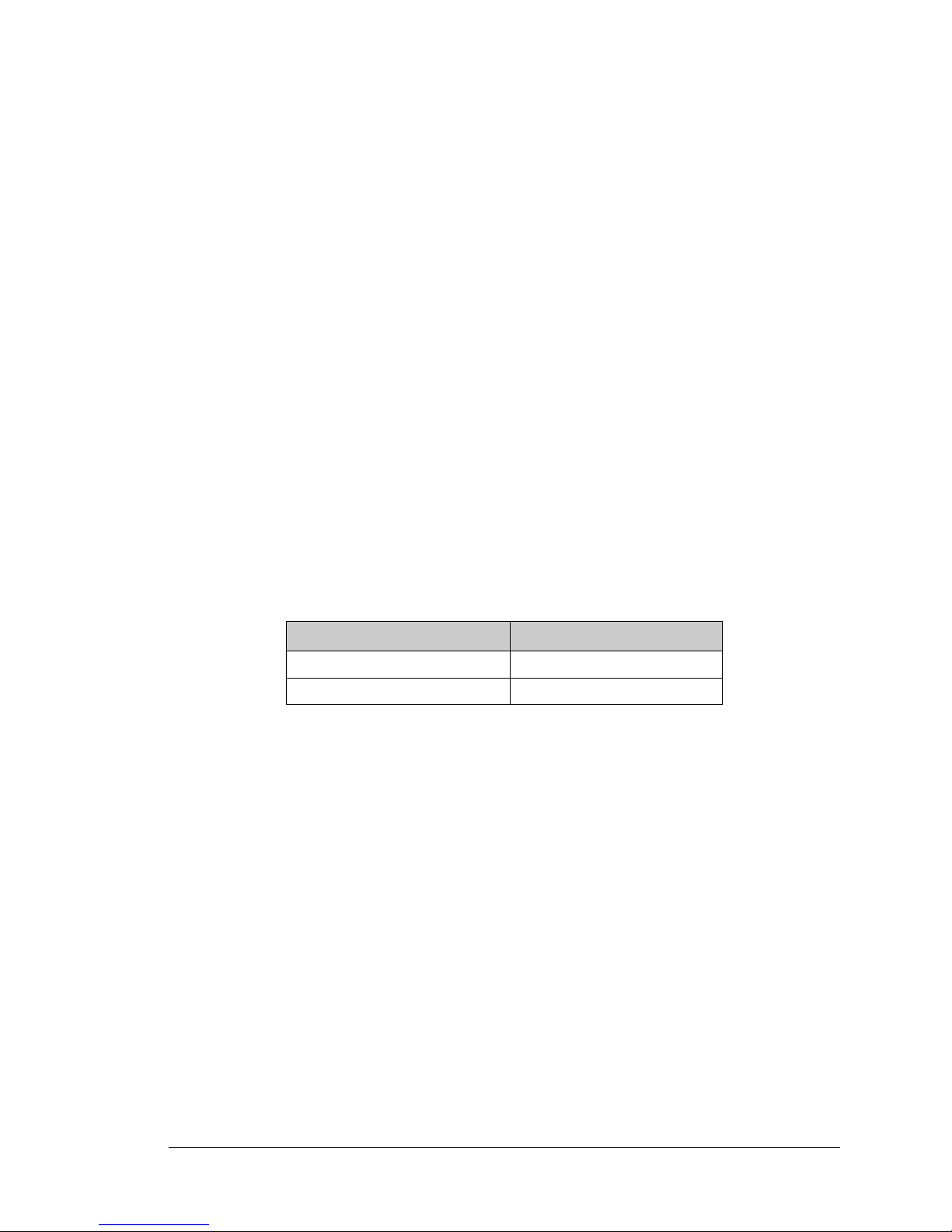
+10 V (12-bit resolution) or ±10 V (11-bit resolution, one bit used for polarity). There are
also four 4–20 mA current outputs. Figure 17 shows the D/A converter outputs.
Figure 17. D/A Converter Outputs
T o stay within the maximum power dissipation of the D/A converter circuit, the maximum
D/A converter output current is 10 mA per channel for the voltage outputs. If you are
using the current outputs, keep the resistance driven by a current output channel below
400 Ω to stay within the power dissipation capabilities of the D/A converter circuit.
As Figure 17 shows, both the voltage and the current outputs for a particular channel are
driven by the same output on the D/A converter chip. As a result, either the anaOutVolts
or the anaOutmAmps function calls will set both the voltage and the current outputs corresponding to a particular channel. For example, if anaOutVolts sets unipolar channel
AV0 to be +10 V, AI0 will be 20 mA; if anaOutVolts sets unipolar channel AV0 to be
+5 V, AI0 will be 12 mA, the midpoint of the 4–20 mA range. It is possible to connect a
load to both the corresponding voltage and current outputs as long as the combined current
consumption does not exceed the 20 mA individual limit.
Because of the “connection” between the analog voltage outputs and the analog current
outputs, the configuration of the analog voltage outputs with the anaOutConfig function
call as unipolar outputs with 12-bit resolution or as bipolar outputs with 11-bit resolution
52.3 kW
DAC
10 kW
AV0
AGND
1.667 V ref.
11 kW
AV1
2.5 V ref.
1.33 kW
1.33 kW
11 kW
11 kW
AI0
AI1
Page 31
User’s Manual 27
also affects the resolution of the 4–20 mA current outputs—you need to configure a voltage output for unipolar operation if you want 12-bit resolution on the associated current
output.
There are other effects on a current output when the associated voltage output is operating
in the bipola r mode. While vol tages of 0 to +10 V still co rrespond to current s of 4 to 20 mA,
the current cannot be determined reliably for voltages below 0 V, and will be “negative” at
voltages below -2.5 V. Thus the current output effectively becomes a “current sink”
instead of a “current source.”
The D/A converter outputs are factory-calibrated and the calibration constants are stored in a
separate EEPROM.
3.5.1 D/A Converter Calibration
To get the best results form the D/A converter, it is necessary to calibrate each mode (unipolar, bipolar, and current) for each of its gains. It is imperative that you calibrate each of
the D/A converter outputs in the same manner as they are to be used in the application.
The calibration table in software only holds calibration constants based on unipolar, bipolar, and voltage or current operation.
Other factors affec ting the calibr ation must be taken i nto
account by calibrating using the same mo de and voltage/current setup as in the intended use.
Sample programs are provided to illustrate how to calibrate the various D/A outputs for
the three operating modes.
These sample programs are found in the DAC subdirectory in SAMPLES\BL2600. See
Section 4.2.5 for more information on these sample programs and how to use them.
Mode Calibrate
Voltage DAC_CAL_VOLTS.C
Current DAC_CAL_MA.C
Page 32
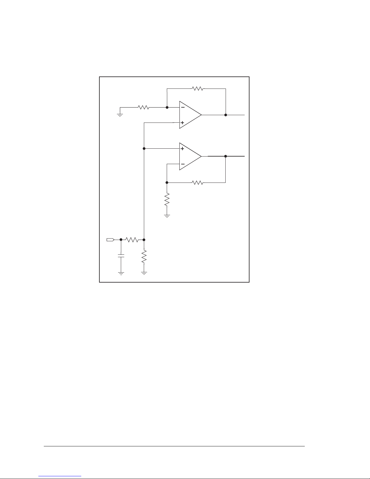
28 Wolf (BL2600)
3.6 Analog Reference Voltage Circuit
Figure 18 shows the analog voltage reference circuit.
Figure 18. Analog Reference Voltages
The A/D converter chip supplies the 2.048 V reference voltage, which is divided in half
and then amplified and buffered to provide the 1.667 V and 2.5 V reference voltages used
by the digital output circuits.
The D/A converter chip provides the reference voltages for the digital inputs to provide
single-ended unipolar or differential measurements [0 V], or to provide single-ended
bipolar measurements [V = (voltage ran ge) ÷ 9]. Becau se the D/A conv erter chip operation
is configured by the anaOutConfig function, it is important to run the anaOutConfig
function before running anaInConfig if you plan to use the digital outputs to ensure that
the reference voltages are established first before the analog inputs are configured.
15.8 kW
11 kW
10 kW
ADREF
100 nF
2.048 V
1.024 V
10 kW
15.8 kW
2.500 V
1.667 V
10 kW
Page 33
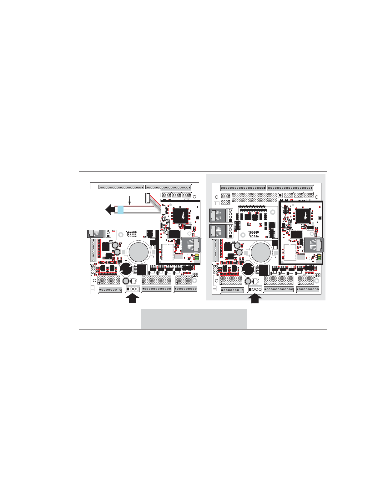
User’s Manual 29
3.7 Programming Cable
The programming cable has a level converter board in the middle of the cable since the
BL2600 programming port supports CMOS logic levels , and not the higher voltage RS -232
levels that are used by PC serial ports. When the programming cable is connected, Dynamic
C running on the PC can hard-reset the BL2600 and cold-boot it. The cold boot includes
compiling and downloading a BIOS program that stays resident while you work. If you
crash the target, Dynamic C will automatically reboot and recompile the BIOS if it senses
that a target communication error occurred or that the BIOS source code has changed.
3.7.1 Switching Between Program Mode and Run Mode
The BL2600 is automatically in Program Mode when the
PROG
connector on the program-
ming cable is attached,
and is automatically in Run Mode when no programming cable is
attached. See Figure 19.
Figure 19. BL2600 Program Mode and Run Mode Set-Up
3.7.2 Detailed Instructions: Changing from Program Mode to Run Mode
1. Disconnect the programming cable from header J1 of the BL2600 module.
2. Reset the BL2600 by unplugging the AC adapter, then plugging it back in.
The BL2600 is now ready to operate in the Run Mode.
3.7.3 Detailed Instructions: Changing from Run Mode to Program Mode
1. Attach the programming cable to header J1 of the BL2600 module.
2. Reset the BL2600 by unplugging the AC adapter, then plugging it back in. Alternatively, you may press <Ctrl-Y> on your PC if Dynamic C is running.
The BL2600 is now ready to operate in the Program Mode.
Power
Power
RESET BL2600 when changing mode:
Remove, then reapply power, or press RESET
after removing or attaching programming cable.
Program Mode
J15
J16
AIN0
AIN1
AIN2
AIN3
JP6
420 mA
AV0 AV1 AV2 AV3 AI0 AI1 AI2 AI3 AGND
GND HOUT0 +HK1 GND HOUT2 +HK3 GND
+HK0 GND HOUT1 +HK2 GND HOUT3
TXC TXF TXE 485 GND
GND RXC RXF RXE 485+
J17
GND HOUT0 +HK1 GND HOUT2 +HK3 GND
+HK0 GND HOUT1 +HK2 GND HOUT3
TXC TXF TXE 485
AIN1 AIN3 AIN5 AIN7 AGND AV1 AV3 AI1 AI3 AGND
AIN0 AIN2 AIN4 AIN6 AGND AV0 AV2 AI0 AI2 AGND
J11
20
19
R43
JP6
R44
R39
R38
R20
R33
R34
U13
R22
R21
R17
C18
C19
U12
R15
C13
R16
C10
R10
U11
J8
R14 R13 C11
AIN0 AIN1 AIN2 AIN3 AIN4 AIN5 AIN6 AIN7 AGND
C12 R12 R11
U10
BT1
C26
C27
D1
U15
C25
J12
J13
C22
R55
R42
C23
C24
R41
R40
R35
R36
R37
U14
R26
R28
R30
R19
R29
R32
R31
R56
R57
L1
R27R25
R23
R24
C20
C21
R18
C16
1
2
25
26
RXE
J14
Q19
D3
Q17D2Q18
RXC
D4
Q20
C34
RXF
485+
C35 C36 C37
JP7
485 TERM.
RESISTOR
C30
R58
R59
R60
U18
C32
C33
RCM2
U17
C31
R9
U16
R8
J10
R7
GND/EGND
RP5
RP6
U2
C4
R5
C5
R6
C6
U4
JA
RCM1
RCM3000 ETHERNET CORE MODULE
U3
RP17RP18
34
33
16
15
1
2
1
2
15
16
33
34
C1
U1
RP3
RP4
GND
+K
DCIN
+5V
JP3,
JP4
AND
JP4
JP1 AND JP2
GND
+K
DCIN
+5V
J4 RABBITNET 1
J6 RABBITNET 0
J7
C14
C17
C15
C78
J9
C9
U9
RP16
C8
U8
R4
R3
RP15
RP14
RP12
RP13
RP11
R1
R2
C7
U6
U7
U5
RP8
RP7
RP9
RP10
C2
Q9
Q10
J5
Q12
Q15Q14 Q16
Q11
Q13
C3
Q1 Q2 Q3 Q4 Q5 Q6 Q7 Q8
JP2
JP1
J1
J2
GND DIN28 DIN24 DIN20 DIN16 GND DIO12 DIO08 DIO04 DIO00
DIN30 DIN26 DIN22 DIN18 +K DIO14 DIO10 DIO06 DIO02 GND
DIN31 DIN27 DIN23 DIN19 +K DIO15 DIO11 DIO07 DIO03 GND
GND DIN29 DIN25 DIN21 DIN17 GND DIO13 DIO09 DIO05 DIO01
GND DIO14 DIO12 DIO10 DIO08 DIO06 DIO04 DIO02 DIO00 GND
+K DIO15 DIO13 DIO11 DIO09 DIO07 DIO05 DIO03 DIO01 GND
GND DIN30 DIN28 DIN26 DIN24 GND DIN22 DIN20 DIN18 DIN16
DIN31 DIN29 DIN27 DIN25 +K DIN23 DIN21 DIN19 DIN17 GND
DIO 0007 PULLS
DIO 0815 PULLS
1
2
39
40
SW1
J3
1
2
DCIN DCIN GND GND
R111
R112
RESET
RP2
RP1
JP3
DIN 1619 PULLS
JP4
DIN 2023 PULLS
DIN 2431 PULLS
JP5
R84
C28
1
2
DS1
J15
J16
AIN0
AIN1
AIN2
AIN3
JP6
420 mA
AV0 AV1 AV2 AV3 AI0 AI1 AI2 AI3 AGND
GND HOUT0 +HK1 GND HOUT2 +HK3 GND
+HK0 GND HOUT1 +HK2 GND HOUT3
TXC TXF TXE 485 GND
GND RXC RXF RXE 485+
J17
GND HOUT0 +HK1 GND HOUT2 +HK3 GND
+HK0 GND HOUT1 +HK2 GND HOUT3
TXC TXF TXE 485
AIN1 AIN3 AIN5 AIN7 AGND AV1 AV3 AI1 AI3 AGND
AIN0 AIN2 AIN4 AIN6 AGND AV0 AV2 AI0 AI2 AGND
J11
20
19
R43
JP6
R44
R39
R38
R20
R33
R34
U13
R22
R21
R17
C18
C19
U12
R15
C13
R16
C10
R10
U11
J8
R14 R13 C11
AIN0 AIN1 AIN2 AIN3 AIN4 AIN5 AIN6 AIN7 AGND
C12 R12 R11
U10
BT1
C26
C27
D1
U15
C25
J12
J13
C22
R55
R42
C23
C24
R41
R40
R35
R36
R37
U14
R26
R28
R30
R19
R29
R32
R31
R56
R57
L1
R27R25
R23
R24
C20
C21
R18
C16
1
2
25
26
RXE
J14
Q19
D3
Q17D2Q18
RXC
D4
Q20
C34
RXF
485+
C35 C36 C37
JP7
485 TERM.
RESISTOR
C30
R58
R59
R60
U18
C32
C33
RCM2
U17
C31
R9
U16
R8
J10
R7
GND/EGND
RP5
RP6
U2
C4
R5
C5
R6
C6
U4
JA
RCM1
RCM3000 ETHERNET CORE MODULE
U3
RP17RP18
34
33
16
15
1
2
1
2
15
16
33
34
C1
U1
RP3
RP4
GND
+K
DCIN
+5V
JP3,
JP4
AND
JP4
JP1 AND JP2
GND
+K
DCIN
+5V
J4 RABBITNET 1
J6 RABBITNET 0
J7
C14
C17
C15
C78
J9
C9
U9
RP16
C8
U8
R4
R3
RP15
RP14
RP12
RP13
RP11
R1
R2
C7
U6
U7
U5
RP8
RP7
RP9
RP10
C2
Q9
Q10
J5
Q12
Q15Q14 Q16
Q11
Q13
C3
Q1 Q2 Q3 Q4 Q5 Q6 Q7 Q8
JP2
JP1
J1
J2
GND DIN28 DIN24 DIN20 DIN16 GND DIO12 DIO08 DIO04 DIO00
DIN30 DIN26 DIN22 DIN18 +K DIO14 DIO10 DIO06 DIO02 GND
DIN31 DIN27 DIN23 DIN19 +K DIO15 DIO11 DIO07 DIO03 GND
GND DIN29 DIN25 DIN21 DIN17 GND DIO13 DIO09 DIO05 DIO01
GND DIO14 DIO12 DIO10 DIO08 DIO06 DIO04 DIO02 DIO00 GND
+K DIO15 DIO13 DIO11 DIO09 DIO07 DIO05 DIO03 DIO01 GND
GND DIN30 DIN28 DIN26 DIN24 GND DIN22 DIN20 DIN18 DIN16
DIN31 DIN29 DIN27 DIN25 +K DIN23 DIN21 DIN19 DIN17 GND
DIO 0007 PULLS
DIO 0815 PULLS
1
2
39
40
SW1
J3
1
2
DCIN DCIN GND GND
R111
R112
RESET
RP2
RP1
JP3
DIN 1619 PULLS
JP4
DIN 2023 PULLS
DIN 2431 PULLS
JP5
R84
C28
1
2
DS1
U1
U6
R28
R38
R41
C5
C3
C9
C8
C12
C17
C23
C30
C18
C29
C35
C33
R29
R37
R39
R40
R42
Y3
C42R35
R31
R27
R25
DS1
R67
R70
J4
C79
Y4
C83
C86
GND
R75
R74
R71
DS3
DS2
R63 R64
C71
C72
C68
C64
C67
L2
U8
R49
R48
C62
R51
C61
R44
R47
C59
C49
C57
L1
R69
R72
R73
C75
C74
R58
C53
C47
C48
C45
C44
C43
JP5
C31
JP3
JP4
C28
C27
C37
C36
C32
R24
R22
C19
R23
C24
R20
C20
R19
C16
C15
R17
R18
R7
R9
R1
R8
C1
R10
R14
C4
SPD LNK ACT
J3
U5
U4
D1
Q1
C39
RP1
U1
U6
R28
R38
R41
C5
C3
C9
C8
C12
C17
C23
C30
C18
C29
C35
C33
R29
R37
R39
R40
R42
Y3
C42R35
R31
R27
R25
DS1
R67
R70
J4
C79
Y4
C83
C86
GND
R75
R74
R71
DS3
DS2
R63 R64
C71
C72
C68
C64
C67
L2
U8
R49
R48
C62
R51
C61
R44
R47
C59
C49
C57
L1
R69
R72
R73
C75
C74
R58
C53
C47
C48
C45
C44
C43
JP5
C31
JP3
JP4
C28
C27
C37
C36
C32
R24
R22
C19
R23
C24
R20
C20
R19
C16
C15
R17
R18
R7
R9
R1
R8
C1
R10
R14
C4
SPD LNK ACT
J3
U5
U4
D1
Q1
C39
RP1
Run Mode
Programming Cable
DIAG
PROG
Colored edge
To
PC COM port
Page 34

30 Wolf (BL2600)
3.8 Other Hardware
3.8.1 Clock Doubler
The BL2600 takes advantage of the Rabbit 3000 microprocessor’s internal clock doubler.
A built-in clock doubler allows half-frequency crystals to be used to reduce radiated emissions. The 44.2 MHz frequency specified for the BL2600 is generated using a 22.12 MHz
resonator.
The clock doubler may be disabled if 44.2 MHz clock speeds are not required. Disabling
the Rabbit 3000 microprocessor’s internal clock doubler will reduce power consumption
and further reduce radiated emissions. The clock doubler is disabled with a simple change
to the BIOS as described below.
3.8.2 Spectrum Spreader
The Rabbit 3000 features a spectrum spreader, which helps to mitigate EMI problems. By
default, the spectrum spreader is on automatically, but it may also be turned off or set to a
stronger setting. The means for doing so is through a simple change to the following BIOS
line in a way that is similar to the clock doubler described above.
#define ENABLE_SPREADER 1 // Set to 0 to disable spectrum spreader.
#define SPREADER_SETTING 0 // 0 = normal spreading, 1 = strong spreading
NOTE: The strong spectrum-spreading sett ing i s n ot rec ommended s ince i t may l imit the
maximum clock speed or the maximum baud rate.
1. Open the BIOS source code file, RABBITBIOS.C in the BIOS directory.
2. Change the line
#define CLOCK_DOUBLED 1 // set to 1 to double clock if
// Rabbit 2000: crystal <= 12.9024 MHz,
// Rabbit 3000: crystal <= 26.7264 MHz,
// or to 0 to always disable clock doubler
to read as follows.
#define CLOCK_DOUBLED 0
3. Save the change using File > Save.
Page 35
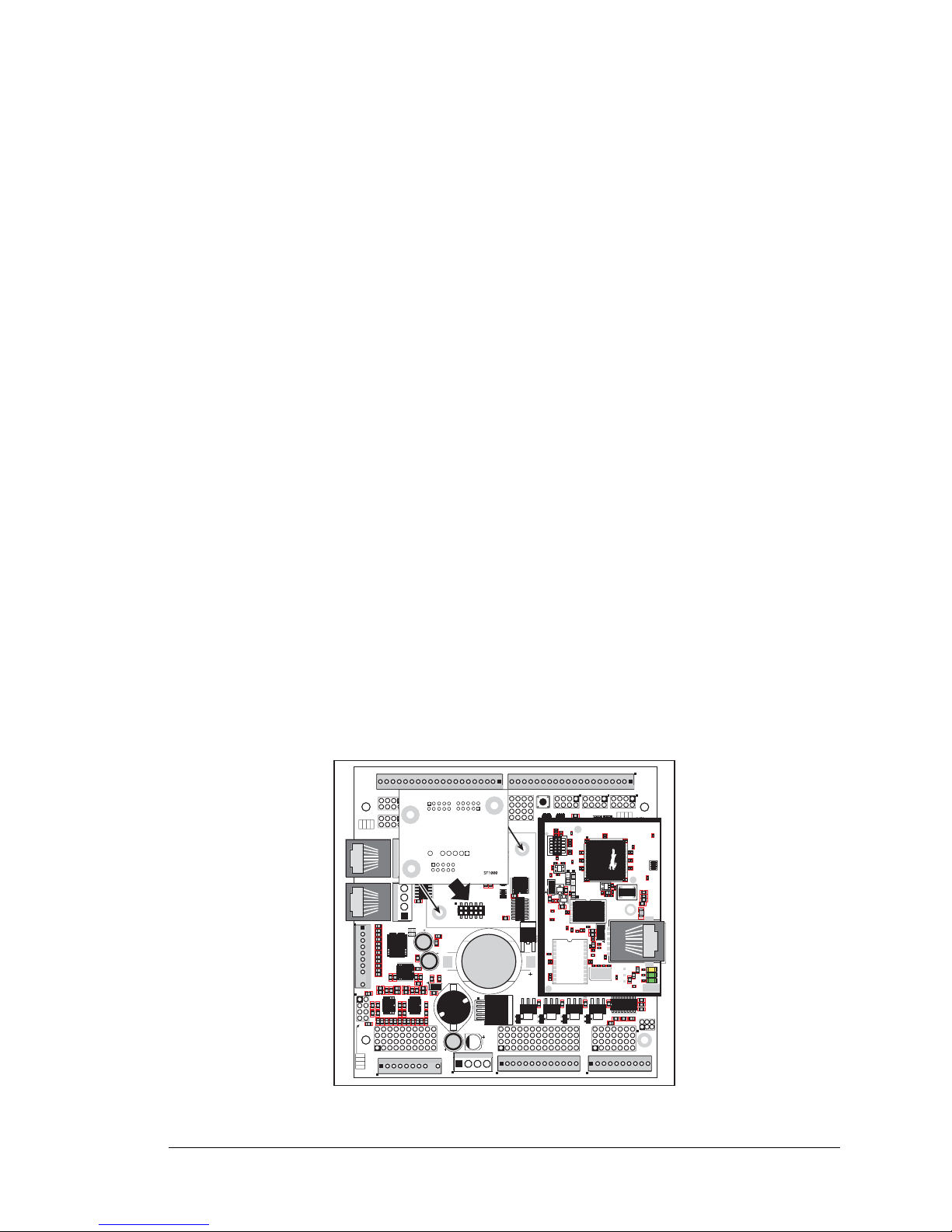
User’s Manual 31
3.9 Memory
3.9.1 SRAM
The BL2600 modules have 512K of program-execution SRAM packaged in an SOIC
case. The BL2600 modules also come with 256K of data SRAM.
3.9.2 Flash M emory
The BL2600 also has 512K of flash memory packaged in a TSOP case.
NOTE: Z-Wor ld rec ommends that any cust omer applications should not be constrain ed
by the sector size of the flash memory since it may be necessary to change the sector
size in the future.
Writing to arbitrary flash memory addresses at run time is also discouraged. Instead,
define a “user block” area to store persistent data. The functions writeUserBlock and
readUserBlock are provided for this.
A Flash Memory Bank Select jumper configuration option based on 0 Ω surface-mounted
resistors exists at header JP4 on the RabbitCore module (BL2600) or at header JP1 on the
RabbitCore module (BL2610). This option, used in conjunction with some configuration
macros, allows Dynamic C to compile two different co-resident programs for the upper
and lower halves of the 512K flash in such a way that both programs start at logical
address 0000. This is useful for applications that require a resident download manager and
a separate downloaded program. See Technical Note 218,
Implementing a Serial Download
Manager for a 256K Flash
, for details.
3.9.3 Serial Flash
Header J9 is provided to allow you to plug in a Z-World SF1000 serial flash. You may use
two ½" (12 mm) spacers with 4-40 × 3/4 screws and nuts to attach the SF1000 securely.
Figure 20. Installation of Optional SF1000 Serial Flash
J15
J16
AIN0
AIN1
AIN2
AIN3
JP6
420 mA
AV0 AV1 AV2 AV3 AI0 AI1 AI2 AI3 AGND
GND HOUT0 +HK1 GND HOUT2 +HK3 GND
+HK0 GND HOUT1 +HK2 GND HOUT3
TXC TXF TXE 485 GND
GND RXC RXF RXE 485+
J17
GND HOUT0 +HK1 GND HOUT2 +HK3 GND
+HK0 GND HOUT1 +HK2 GND HOUT3
TXC TXF TXE 485
AIN1 AIN3 AIN5 AIN7 AGND AV1 AV3 AI1 AI3 AGND
AIN0 AIN2 AIN4 AIN6 AGND AV0 AV2 AI0 AI2 AGND
J11
20
19
R43
JP6
R44
R39
R38
R20
R33
R34
U13
R22
R21
R17
C18
C19
U12
R15
C13
R16
C10
R10
U11
J8
R14 R13 C11
AIN0 AIN1 AIN2 AIN3 AIN4 AIN5 AIN6 AIN7 AGND
C12 R12 R11
U10
BT1
C26
C27
D1
U15
C25
J12
J13
C22
R55
R42
C23
C24
R41
R40
R35
R36
R37
U14
R26
R28
R30
R19
R29
R32
R31
R56
R57
L1
R27R25
R23
R24
C20
C21
R18
C16
1
2
25
26
RXE
J14
Q19
D3
Q17D2Q18
RXC
D4
Q20
C34
RXF
485+
C35 C36 C37
JP7
485 TERM.
RESISTOR
C30
R58
R59
R60
U18
C32
C33
RCM2
U17
C31
R9
U16
R8
J10
R7
GND/EGND
RP5
RP6
U2
C4
R5
C5
R6
C6
U4
JA
RCM1
RCM3000 ETHERNET CORE MODULE
U3
RP17 RP18
34
33
16
15
1
2
1
2
15
16
33
34
C1
U1
RP3
RP4
GND
+K
DCIN
+5V
JP3,
JP4
AND
JP4
JP1 AND JP2
GND
+K
DCIN
+5V
J4 RABBITNET 1
J6 RABBITNET 0
J7
C14
C17
C15
C78
J9
C9
U9
RP16
C8
U8
R4
R3
RP15
RP14
RP12
RP13
RP11
R1
R2
C7
U6
U7
U5
RP8
RP7
RP9
RP10
C2
Q9
Q10
J5
Q12
Q15Q14 Q16
Q11
Q13
C3
Q1 Q2 Q3 Q4 Q5 Q6 Q7 Q8
JP2
JP1
J1
J2
GND DIN28 DIN24 DIN20 DIN16 GND DIO12 DIO08 DIO04 DIO00
DIN30 DIN26 DIN22 DIN18 +K DIO14 DIO10 DIO06 DIO02 GND
DIN31 DIN27 DIN23 DIN19 +K DIO15 DIO11 DIO07 DIO03 GND
GND DIN29 DIN25 DIN21 DIN17 GND DIO13 DIO09 DIO05 DIO01
GND DIO14 DIO12 DIO10 DIO08 DIO06 DIO04 DIO02 DIO00 GND
+K DIO15 DIO13 DIO11 DIO09 DIO07 DIO05 DIO03 DIO01 GND
GND DIN30 DIN28 DIN26 DIN24 GND DIN22 DIN20 DIN18 DIN16
DIN31 DIN29 DIN27 DIN25 +K DIN23 DIN21 DIN19 DIN17 GND
DIO 0007 PULLS
DIO 0815 PULLS
1
2
39
40
SW1
J3
1
2
DCIN DCIN GND GND
R111
R112
RESET
RP2
RP1
JP3
DIN 1619 PULLS
JP4
DIN 2023 PULLS
DIN 2431 PULLS
JP5
R84
C28
1
2
DS1
U1
U6
R28
R38
R41
C5
C3
C9
C8
C12
C17
C23
C30
C18
C29
C35
C33
R29
R37
R39
R40
R42
Y3
C42R35
R31
R27
R25
DS1
R67
R70
J4
C79
Y4
C83
C86
GND
R75
R74
R71
DS3
DS2
R63 R64
C71
C72
C68
C64
C67
L2
U8
R49
R48
C62
R51
C61
R44
R47
C59
C49
C57
L1
R69
R72
R73
C75
C74
R58
C53
C47
C48
C45
C44
C43
JP5
C31
JP3
JP4
C28
C27
C37
C36
C32
R24
R22
C19
R23
C24
R20
C20
R19
C16
C15
R17
R18
R7
R9
R1
R8
C1
R10
R14
C4
SPD LNK ACT
J3
U5
U4
D1
Q1
C39
RP1
Page 36

32 Wolf (BL2600)
Page 37

User’s Manual 33
4. SOFTWARE
Dynamic C is an integrated development system for writing
embedded software. It runs on an IBM-compatible PC and is
designed for use with Z-World single-board computers and other
devices based on the Rabbit microprocessor.
Chapter 4 provides the libraries, function calls, and sample programs related to the BL2600.
4.1 Running Dynamic C
You have a choice of doing your software development in the flash memory or in the static
RAM included on the BL2600. The advantage of working in RAM is to save wear on the
flash memory, which is limited to about 100,000 write cycles.
NOTE: An application can be developed in RAM, but cannot run sta nda lon e fr om RAM
after the programming ca ble is disconn ected. S tandalone ap plications can on ly run from
flash memory.
The disadvantage of using flash memory for debug is that interrupts must be disabled for
approximately 5 ms whenever a break point is set in the program. This can crash fast interrupt routines that are running while you stop at a break point or single-step the program.
Flash memory or RAM is selected on the Options > Compiler menu.
Page 38

34 Wolf (BL2600)
4.1.1 Upgrading Dynamic C
4.1.1.1 Patches and Updates
Dynamic C patches that focus on patches and updates are available from time to time.
Check the Web site
• www.zworld.com/support/
for the latest patches, workarounds, and updates.
The default installation of a patch or update is to install the file in a directory (folder) dif-
ferent from that of the original Dynamic C installation. Z-World recommends using a different directory so that you can verify the operation of the patch or update without
overwriting the existing Dynamic C installation. If you have made any changes to the
BIOS or to libraries, or if you have programs in the old directory (folder), make these
same changes to the BIOS or libraries in the new directory containing the patch. Do not
simply copy over an entire file since you may overwrite an update; of course, you may
copy over any programs you have written. Once you are sure the new patch or update
works entirely to your satisfaction, you may retire the existing installation, but keep it
available to handle legacy applications.
4.1.1.2 Upgrades
Dynamic C installations are designed for use with the board they are included with, and
are included at no charge as part of our low-cost kits. Dynamic C is a complete software
development system, but does not include all the Dynamic C features. Z-W orld also offers
for sale add-on Dynamic C modules containing the popular µC/OS-II real-time operating
system, as well as PPP, Advanced Encryption Standard (AES), RabbitWeb, FAT File System, Secure Socket Layer (SSL) and other select libraries. In addition to the Web-based
technical support included at no extra charge, a one-year telephone-based technical support module is also available for purchase.
Page 39

User’s Manual 35
4.2 Sample Programs
Sample programs are provided in the Dynamic C Samples folder. The sample program
PONG.C demonstrates the output to the STDIO window.
The various directories in the
Samples folder contain specific sa mple pr ograms tha t illus-
trate the use of the corresponding Dynamic C libraries.
The
BL2600 folder provides sample programs specific to the BL2600. Each sample pro-
gram has comments that describe the purpose and function of the program. Follow the
instructions at the beginning of the sample program.
T o run a sample program , open it with the
File menu (if it is not still op en), compi le it using
the Compile menu, and then run it by selecting Run in the Run menu. The BL2600 must
be in Program mode (see Section 3.7, “Programming Cable,”) and must be connected to a
PC using the programming cable as described in Section 2.2, “BL2600 Connections.”
More complete information on Dynamic C is provided in the Dynamic C User’s Manual.
TCP/IP specific functions are described in the Dynamic C TCP/IP User’s Manual. Infor-
mation on using the TCP/IP features and sample programs is provided in Section 5,
“Using the TCP/IP Features.”
4.2.1 General BL2600 Sample Programs
The following sample programs are found in the SAMPLES\BL2600 folder.
•
BOARD_ID.C—This program is used to identify the model of BL2600 being used, and
displays that information in the
STDIO window.
4.2.2 Digital I/O
The following sample programs are found in the IO subdirectory in SAMPLES\BL2600.
•
DIGIN.C—Demonstrates the use of the digital inputs. Using the Demonstration Board,
you can see an input channel toggle from HIGH to LOW when pressing a pushbutton
on the Demonstration Board. See Appendix D for hookup instructions for the Demonstration Board. This sample program does not explicitly configure any of the configurable I/O, so all the configurable I/O are available by default as digital inputs.
• DIGINBANK.C—Demonstrates the use of digInBank to read digital inputs. Using the
Demonstration Board, you can see an input channel toggle from HIGH to LOW when
pressing a pushbutton on the Demonstration Board. See Appendix D for hookup
instructions for the Demonstration Board. This sample program does not explicitly configure any of the configurable I/O, so all the configurable I/O are available by default as
digital inputs.
• DIGOUT.C—Demonstrates the use of the configurable I/O sinking outputs. Using the
Demonstration Board, you can see an LED toggle on/off via a sinking output. See
Appendix D for hookup instructions for the Demonstration Board.
• DIGOUTBANK.C—Demonstrates the use of digInBank to control the configurable I/O
sinking outputs. Using the Demonstration Board, you can see an LED toggle on/off via
a sinking output. See Appendix D for hookup instructions for the Demonstration Board.
Page 40

36 Wolf (BL2600)
• HIGH_CURRENT_IO.C—Demonstrates the use of the high-current outputs configured
as either sinking or sourcing outputs. High-current output HOUT0 is configured for
sourcing to provide power to the Demonstration Board. Outputs HOUT1 and HOUT2
are configured to demonstrate tristate operation to toggle the LEDs on the Demonstration Board. Output HOUT3 is configured as a sinking output to toggle an LED on the
Demonstration Board. See Appendix D for hookup instructions for the Demonstration
Board.
•
PWM.C—Demonstrates the use of the four PWM channels on Parallel Port F (PF4–PF7)
on pins DIN20–DIN23. The PWM signals are set for a frequency of 10 kHz with the
duty cycle adjustable from 1 to 99% by the user. Since the output voltage swing is 0 V
to 2.5 V DC, the PWM outputs should interface only with TTL-compatible components. Follow these instructions when running this sample program.
1. Connect the jumper across pins 7–8 on header JP4 to select the GND option.
2. Once you have compiled and run thi s pr ogr am, you may chang e duty cycle for a given PWM channel via the Dynamic C
STDIO window and use either an oscilloscope or a voltmeter to view the
output. When monitoring with a voltmeter, you can compute the expected voltage Vout = PWM
percentage × 2.5 V.
4.2.3 Serial Communication
The following sample programs are found in the RS232 subdirectory in SAMPLES\BL2600.
• PARITY.C—This sample program repeatedly sends byte values 0–127 from Serial Port F
to Serial Port C. The program switches between generating parity and not generating
parity on Serial Port F. Serial Port C will always be checking parity, so parity errors
should occur during every other sequence. The results are displayed in the Dynamic C
STDIO window.
Connect TxF to RxC before compiling and running this sample program.
NOTE: For the sequence that does yield parity errors, the errors won't occur for each
byte received. Th is is be cause certain byte patte rns alon g with th e stop bit wil l appear to
generate the correct parity for the UART.
• SIMPLE3WIRE.C—This program demonstrates basic RS-232 serial communication.
Connect TxC to RxF on header J17 and connect TxF to RxC on header J17 before compiling and running this sample program.
• SIMPLE5WIRE.C—This program demonstrates 5-wire RS-232 serial communication.
Connect TxC to RxC on header J17 and conn ect TxF to RxF on header J17 before compiling and running this sample program.
TxF and RxF become the flow control RTS and CTS. To test flow control, disconnect
RTS from CTS while running this program. Characters should stop printing in the
Dynamic C STDIO window and should resume when RTS and CTS are connected again
Page 41

User’s Manual 37
The following sample programs are found in the RS485 subdirectory in SAMPLES\BL2600.
•
MASTER.C—This program demonstrates a simple RS-485 transmission of lower case
letters to a slave. The slave will send back converted upper case letters back to the
master BL2600 and display them in the
STDIO window. Use SLAVE.C to program the
slave. Make the following connections between the master and slave:
485+ to 485+
485- to 485GND to GND
• SLAVE.C—This program demonstrates a simple RS-485 transmission of lower case
letters to a slave. The slave will send back converted upper case letters back to the
master BL2600 and display them in the
STDIO window . Use MASTER.C to program the
master BL2600.
4.2.4 A/D Converter Inputs
The following sample programs are found in the
ADC subdirectory in SAMPLES\BL2600.
NOTE: The calibration sample programs will overwrite the calibration constants set at
the factory.
• ADC_CAL_DIFF.C—Demonstrates how to recalibrate a differential A/D converter
channel using two known voltages to generate two coefficients, gain and offset, which
are rewritten into the reserved EEPROM. The voltage that is being monitored is displayed continuously.
• ADC_CAL_MA.C—Demonstrates how to recalibrate a milli-amp A/D converter channel
using two known currents to generate two coefficients, gain and offset, which are
rewritten into the reserved EEPROM. The current that is being monitored is displayed
continuously.
• ADC_CAL_SE_BIPOLAR.C—Demonstrates how to recalibrate a single-ended bipolar
A/D converter channel using two known voltages to generate two coefficients, gain and
offset, which are rewritten into the reserved EEPROM. The voltage that is being monitored is displayed continuously.
• ADC_CAL_SE_UNIPOLAR.C—Demonstrates how to r ecalibrate a single-ended unipolar
A/D converter channel using two known voltages to generate two coefficients, gain and
offset, which are rewritten into the reserved EEPROM. The voltage that is being monitored is displayed continuously.
• ADC_RD_CALDATA.C—Demonstrates how to display the two calibration coefficients,
gain and offset, in the Dynamic C STDIO window for each channel and mode of
operation.
• AD_RD_DIFF.C—Demonstrates how to read and display voltage and equivalent values
for a differential A/D converter channel using calibration coefficients previously stored
in the EEPROM. The user selects to display either the raw data or the voltage equivalent.
• AD_RD_MA.C—Demonstrates how to read and display voltage and equivalent values
for a milli-amp A/D converter channel using calibration coefficients previously stored
in the EEPROM. The user selects to display either the raw data o r the current equivalent.
Page 42

38 Wolf (BL2600)
• AD_RD_SE_BIPOLAR.C—Demonstrates how to read and display the voltage of all single-ended A/D converter channels using calibration coefficients previously stored in
the EEPROM.
•
AD_RD_SE_UNIPOLAR.C—Demonstrates how to read and display the voltage of all
single-ended A/D converter channels using calibration coefficients previously stored in
the EEPROM.
4.2.5 D/A Converter Outputs
The following sample programs are found in the
DAC subdirectory in SAMPLES\BL2600.
NOTE: The calibration sample programs will overwrite the calibration constants set at
the factory.
• DAC_CAL_MA.C—Demonstrates how to recalibrate a D/A converter channel using a
known current to generate calibration constants, which are written into the reserved
EEPROM.
•
DAC_CAL_VOLTS.C—Demonstrates how to recalibrate a D/A converter channel using
a known voltage to generate calibration constants, which are written into the reserved
EEPROM.
• DAC_MA_ASYNC.C—Demonstrates how to output a current that can be read with an
ammeter. The output current is computed with using the calibration constants that are
stored in the reserved EEPROM.
The D/A converter circuit is set up for asynchronous operation, which updates the D/A
converter output at the time it's being written via the anaOut or anaOutmAmps function
calls.
• DAC_MA_SYNC.C—Demonstrates how to output a current that can be read with an
ammeter. The output current is computed with using the calibration constants that are
stored in the reserved EEPROM.
The D/A converter circuit is set up for synchronous operation, which updates the D/A
converter output when the anaOutStrobe function call executes. The outputs will be
updated with values previously written via the anaOut or anaOutmAmps function calls.
• DAC_RD_CALDATA.C—Demonstrates how to display the calibration coefficients, gain
and offset, in the Dynamic C STDIO window for each channel and mode of operation.
• DAC_VOLT_ASYNC.C—Demonstrates how to output a voltage that can be read with a
voltmeter. The output voltage is computed with using the calibration constants that are
stored in the reserved EEPROM.
The D/A converter circuit is set up for asynchronous operation, which updates the D/A
converter output at the time it's being written via the anaOut or anaOutVolts function
calls.
Page 43

User’s Manual 39
• DAC_VOLT_SYNC.C—Demonstrates how to output a voltage that can be read with a
voltmeter. The output voltage is computed with using the calibration constants that are
stored in the reserved EEPROM.
The D/A converter circuit is set up for synchronous operation, which updates the D/A
converter output when the anaOutStrobe function call executes. The outputs will be
updated with values previously written via the
anaOut or anaOutVolts function calls.
4.2.6 Use of BL2600 with SF1000 Serial Flash Card
The following sample programs found in the SF1000 subdirectory in SAMPLES\BL2600
demonstrate the use of the optional SF1000 serial flash card on the BL2600. The SF1000
User’s Manual contains additional information and API functions for the SF1000.
•
FLASH_PATTERN_INSPECT.C—Writes a pattern to the first 100 sectors of the
SF1000, which can then be inspected or cleared by the user. The user then has the
option to either inspect or clear a page of serial flash memory.
•
SFLASH_TEST.C—Demonstrates how to read and write data from/to the SF1000.
Once the sample program is compiled and run, it displays a message in the Dynamic C
STDIO window to report whether the test was successful.
4.2.7 TCP/IP Sample Programs
TCP/IP sample programs are described in Chapter 5.
4.3 BL2600 Libraries
Two library directories provide libraries of function calls that are used to develop applications for the BL2600.
• BL2600—libraries associated with features specific to the BL2600. The functions in the
BL26xx.LIB library are described in Section 4.4, “BL2600 Function APIs.”
• RN_CFG_BL26.LIB—used to configure the BL2600 for use with RabbitNet peripheral
boards.
• TCPIP—libraries specific to using TCP/IP functions on the BL2600. Further information about TCP/IP is provided in Chapter 5, “Using the TCP/IP Features.”
Page 44

40 Wolf (BL2600)
4.4 BL2600 Function APIs
4.4.1 Board Initialization
Call this function at the beginning of your program. This function initializes the system I/O ports and
loads all the A/D converter and D/A converter calibration constants from flash memory into SRAM for
use by your p rogram.
The ports are initialized according to Table A-3 in Appendix A.
SEE ALSO
digOut, digIn, serMode, anaOut, anaIn, anaInDriver, anaOutDriver
void brdInit (void);
Page 45

User’s Manual 41
4.4.2 Digital I/O
Configures a high-current output to be either a sinking or a sourcing output. This configuration information is also used to initially set the output to the off state for the given hardware output configuration. The
configuration options are described below.
NOTE: Configuring a given output channel for tristate operation using the digHTriState-
Config function will override the configuration set by the digHoutConfig function.
NOTE: The brdInit function must be executed before calling digHOutConfig.
NOTE: You must execute the digHOutConfig function to set the high-current drivers to be
either sinking or sourcing. A runtime error will occur in digHOut if digHOutConfig has
not executed.
NOTE: The extra digital outputs resulting from the configuration of DIO00–DIO15 as digital out-
puts are sinking outputs only and cannot be configured with digHOutConfig.
PARAMETER
configuration is a 1-byte parameter where 4 bits are used for the high-current outputs HOUT0–
HOUT3.
Bit 3 = high-current output channel HOUT3
Bit 2 = high-current output channel HOUT2
Bit 1 = high-current output channel HOUT1
Bit 0 = high-current output channel HOUT0
(bits 4–7 are not used)
The high-current outputs can be configured to be sinking or sourcing outputs by setting the corresponding bit to an 0 or 1: 0 = sinking, 1 = sourcing.
RETURN VALUE
None.
SEE ALSO
brdInit, digHout, digHTriStateConfig, digHoutTriState
EXAMPLE
configuration = 0x0C
0x06 = 00001100 (bits 7–0)
HOUT3 is sourcing
HOUT2 is sourcing
HOUT1 is sinking
HOUT0 is sinking
void digHoutConfig(char configuration);
Page 46

42 Wolf (BL2600)
Sets the state of a high-current digital output (HOUT0–HOUT3) to a logic 0, logic 1, or high impedance.
Remember to call the brdInit and the digHOutConfig functions b efore executing this function .
A runtime error will occur for the following conditions:
1. channel or state out of range.
2. brdInit or digHOutConfig was not executed before executing digHOut.
3. If you try to use a channel that is configured as a tristate output by digHTriStateConfig.
PARAMETERS
channel is the output channel number (0–3).
state sets a given channel to one of the following output states depending on how the output was con-
figured by digHoutConfig.
Sinking configuration:
0 = connect the load to GND
1 = put the output in a high-impedance state
Sourcing configuration:
0 = put the output in a high-impedance state
1 = connects the load to +K(0–3)
RETURN VALUE
None.
SEE ALSO
brdInit, digHOutConfig, digHoutTriState, digOut
void digHOut(int channel, int state);
Page 47

User’s Manual 43
Configures whether a high-current output is a tristate type output. This configuration information is also
used to initially set the output to the off state for the given hardware output configuration. The configuration options are describe d below.
PARAMETER
configuration is a 1-byte parameter where 4 bits are used for the high-current outputs HOUT0–
HOUT3.
Bit 3 = high-current output channel HOUT3
Bit 2 = high-current output channel HOUT2
Bit 1 = high-current output channel HOUT1
Bit 0 = high-current output channel HOUT0
(bits 4–7 are not used)
The high-current outputs can be configured as tristate outputs by setting the corresponding bit to a 0 or 1:
0 = disable operation as tristate output, 1 = enable operation as tristate output.
RETURN VALUE
None.
SEE ALSO
brdInit, digHout, dgigHoutConfig, digHoutTriState
EXAMPLE
configuration = 0x09
0x09 = 00001001 (remember these bits are bits 7–0)
HOUT3tristate output is enabled
HOUT2 tristate output is disabled
HOUT1 tristate output is disabled
HOUT0 tristate output is enabled
void digHTriStateConfig(char configuration);
Page 48

44 Wolf (BL2600)
Sets the state of a high-current digital output (HOUT0–HOUT3) to a logic 0, logic 1, or high impedance.
Remember to call the brdInit and the digHTriStateConfig functions before executing this
function.
A runtime error will occur for the following conditions:
1. channel or state out of range.
2. brdInit or digHTritateConfig was not executed before executing digHOutTriState.
3. If you try to use a channel that is not configured as a tristate output by digHTriStateConfig.
PARAMETERS
channel is the output channel number (0–3).
state sets a given channel to one of the following output states depending on how the output was con-
figured by digHTriStateConfig.
Trisate configuration:
0 = connect the load to GND
1 = connects the load to +K(0–3)
2 = put the output in a high-impedance state
RETURN VALUE
None.
SEE ALSO
brdInit, digHout, digHOutConfig, digHTriStateConfig
void digHoutTriState(int channel, int state);
Page 49

User’s Manual 45
Configures any of the 16 configurable I/O channels to be a sinking output. This configuration information is then used by the digOut function to determine whe ther a given channel is configured to be an
output. If it is not, digOut will prevent the given channel from being used by the digOut function.
The configuration options are described below.
PARAMETER
configuration is a 16-bit parameter for which each bit corresponds to a configurable I/O channel (0–
15). An output channel is enabled by setting the corresponding bit number to a logic one.
Bit 15 = output channel DIO15
Bit 14 = output channel DIO14
Bit 13 = output channel DIO13
Bit 12 = output channel DIO12
Bit 11 = output channel DIO11
Bit 10 = output channel DIO10
Bit 9 = output channel DIO09
Bit 8 = output channel DIO08
Bit 7 = output channel DIO07
Bit 6 = output channel DIO06
Bit 5 = output channel DIO05
Bit 4 = output channel DIO04
Bit 3 = output channel DIO03
Bit 2 = output channel DIO02
Bit 1 = output channel DIO01
Bit 0 = output channel DIO00
The configurable I/O are configured to be sinking by setting the corresponding bit to 1; setting the bit to
0 disables that channel for output operation.
RETURN VALUE
None.
SEE ALSO
brdInit, digHout, dgigHoutConfig, digHoutTriState
EXAMPLE
configuration = 0x8005
0x8005 = 10000000000001 01 (bi ts 15– 0)
DIO15, DIO02, and DIO00 have been enabled for use as sinking outputs. The remaining configurable
I/O are locked out from being used by the digOut function.
void digOutConfig(int configuration);
Page 50

46 Wolf (BL2600)
Sets the state of a configurable I/O channel (DIO00–DIO15) configured as a sinking digital output to a
logic 0 or a logic 1. This function only allows control of channels that are configured to be an output by
the digOutConfig function.
Remember to call the brdInit and the digOutConfig functions before executing this function.
A runtime error will occur for the following conditions:
1. channel or state out of range.
2. brdInit or digOutConfig was not executed before executing digOut.
3. If you try to use a channel that is not configured as a digital output by digOutConfig.
PARAMETERS
channel is the output channel number (0–15).
state sets a given channel to one of the following output states.
0 = connect the load to GND
1 = put the output in a high-impedance state
RETURN VALUE
None.
SEE ALSO
brdInit, digHout, digOutConfig, digBankOut, digIn
void digOut(int channel, int state);
Page 51

User’s Manual 47
Sets the state of a bank of configurable I/O channels (DIO00–DIO15) configured as sinking digital outputs to a logic 0 or a logic 1. This function only allows control of channels that are configured to be an
output by the digOutConfig function.
Remember to call the brdInit and the digOutConfig functions before executing this function.
A runtime error will occur for the following conditions:
1. bank is out of range.
2. brdInit or digOutConfig was not executed before executing digOutBank.
PARAMETERS
bank is 0 or 1.
0 = DIO00–DIO07
1 = DIO08–DIO15
data is a value to be written to the specified digital output bank. The data format and bitwise value are
as follows.
0 = connect the load to GND
1 = put the output in a high-impedance state
RETURN VALUE
None.
SEE ALSO
brdInit, digHout, digOutConfig, digBankOut, digIn
void digOutBank(char bank, char data);
Data For m at
Data D7 D6 D5 D4 D3 D2 D1 D0
Bank 0 DIO07 DIO06 DIO05 DIO04 DIO03 DIO02 DIO01 DIO00
Bank 1 DIO15 DIO14 DIO13 DIO12 DIO11 DIO10 DIO09 DIO08
Page 52

48 Wolf (BL2600)
Reads the state of a digital input channel. If a configurable I/O chann el (DIO 00 –DIO 15 ) that was configured as a digital output is read by digIn, then the value read will be the state of the output channel.
A run-time error will occur for the following conditions:
1. channel out of range.
2. brdInit was not executed before executing digIn.
PARAMETER
channel is the input channel number (0–15 for DIO00–DIO15, 16–31 for IN16–IN31).
RETURN VALUE
The logic state of the specified channel (0 = low or 1 = high).
SEE ALSO
brdInit, digOut, digOutConfig, digInBank
Reads the state of a bank of 8 digital input channels. If a configurable I/O channel (DIO00–DIO15) that
was configured as a digital output is read b y digInBank, then the value returned will be the s tate of the
output channel.
A run-time error will occur for the following conditions:
1. bank out of rang e.
2. brdInit was not executed before executing digInBank.
PARAMETER
bank is the bank of digital input channels to read.
0 = DIO00–DIO07 (bank 0)
1 = DIO08–DIO15 (bank 1)
2 = IN16–IN23 (bank 2)
3 = IN24–IN31 (bank 3)
RETURN VALUE
The logic state of each channel in the specified bank (0 = low or 1 = high). The data is returned as a byte,
with each bit representing the state of a particular channel in the bank ordered from the most significant
bit to the least significant bit.
SEE ALSO
brdInit, digOut, digOutConfig, digInBank
int digIn(int channel);
char digInBank(int bank);
Page 53
User’s Manual 49
4.4.3 Serial Co mmunication
Library files included with Dynamic C provide a full range of serial communications support. The RS232.LIB library provides a set of circular-buffer-based serial functions. The
PACKET.LIB library provides packet-based serial functions where packets can be delim-
ited by the 9th bit, by transmission gaps, or with user-defined special characters. Both
libraries provide blocking functions, which do not return until they are finished transmitting or receiving, and nonblocking functions, which must be called repeatedly until they
are finished. For more information, see the Dynamic C User’s Manual and T echnical Note
213, Rabbit 2000 Serial Port Software.
Use the following function calls with the BL2600.
User interface to set up BL2600 serial communication lines. Call this function after serXOpen().
Whether you are opening one or multiple serial por ts, this funct ion must be execute d after executing t he
last serXOpen function AND before you start using any of the s erial ports. This function i s non -reentr ant.
If Mode 1 is selected, CTS/RT S flow control is exercised using the serCflowcontrolOn and
serCflowcontrolOff functions from the RS232.LIB library.
PARAMETER
mode is the defined serial port configuration.
RETURN VALUE
0 if valid mode selected, 1 if not.
SEE ALSO
brdInit, ser485Tx, ser485Rx
int serMode(int mode);
Mode
Serial Port
C F E
0 RS-232, 3-wire RS-232, 3-wire RS-232, 3-wire
1 RS-232, 3-wire RS-232, 3-wire RS-485
2 RS-232, 5-wire RTS/CTS RS-232, 3-wire
3 RS-232, 5-wire RTS/CTS RS-485
Page 54

50 Wolf (BL2600)
Enables the RS-485 transmitter. serMode must be executed before running this function.
NOTE: Transmitted data are echoed back into the receive data buffer. The echoed data
could be used to identify when to disable the transmitter by using one of the following
methods.
Byte mode—disables the transmitter after the byte that is transmitted is detected in the
receive data buffer.
Block data mode—disable the transmitter after the same number of bytes transmitted are
detected in the receive data buffer.
RETURN VALUE
None.
SEE ALSO
brdInit, serMode, ser485Rx
Disables the RS-485 transmitter. This puts you in listen mode, which allows you to receive data from the
RS-485 interface. serMode must be executed before running this function.
RETURN VALUE
None.
SEE ALSO
brdInit, serMode, ser485Tx
void ser485Tx(void);
void ser485Rx(void);
Page 55

User’s Manual 51
4.4.4 A/D Converter Inputs
Configures an A/D converter input channel pair for a given mode of operation. This function must be
called before accessing the A/D converter chip.
NOTE: If you plan to configure the D/A converter chip usi ng anaOutConfig, you must
call
anaOutConfig before executing anaInConfig. This is because the A/D con-
verter uses internal channels 4–7 on the D/A converter chip to bias the A/D converter
input circuit.
PARAMETERS
ch_pair are the channel pairs:
0 = channels 0 and 1
1 = channels 2 and 3
2 = channels 4 and 5
3 = channels 6 and 7
opmode selects the mode of operation for the channel pair on A/D converter:
0 = Single-E nded unipolar (0–10 V)
1 = Single-E nded bipolar (± 10 V)
2 = Differential bipolar (±20 V)
3 = 4–20 mA
RETURN VALUE
None.
SEE ALSO
brdInit, anaInCalib, anaInDriver, anaIn, anaInVolts, anaInmAmps, anaInDiff
void anaInConfig(int ch_pair, int opmode);
Page 56
52 Wolf (BL2600)
Calibrates the response of a given A/D converter channel as a linear function using the two conversion
points provided. Gain and offset constants are calculated and placed into global table _adcInCalib.
PARAMETERS
channel is the analog input channel number (0 to 7) corresponding to AIN0–AIN7
opmode is the mode of operation for the specified channel. Use one of the following macros to set the
mode for the channel being configured.
0 = Single-E nded unipolar (0–20 V)
1 = Single-E nded bipolar (± 10 V)
2 = Differential bipolar (±20 V)
3 = 4–20 mA
gaincode is the gain code of 0 to 7 (use a gain code of 4 for 4–20 mA operation)
value1 is the first A/D converter value (0–4095).
volts1 is the voltage corresponding to the first A/D converter value.
value2 is the second A/D converter value (0–4095).
volts2 is the voltage corresponding to the second A/D converter value.
int anaInCalib(int channel, int opmode,
int gaincode, int value1, float volts1,
int value2, float volts2);
channel
Single-Ended Differential 4–20 mA
0 +AIN0 +AIN0 -AIN1 +AIN0
1 +AIN1 — +AIN1
2 +AIN2 +AIN2 -AIN3 +AIN2
3 +AIN3 — +AIN3
4 +AIN4 +AIN4 -AIN5
5+AIN5 —
6 +AIN6 +AIN6 -AIN7
7+AIN7 —
Gain Code Macro
Voltage Range
Single-Ended
Unipolar
Single-Ended
Bipolar
Differential
Bipolar
0 GAIN_X1 0–20 V ±10 V ± 20 V
1 GAIN_X2 0–10 V ±5 V ± 10 V
2 GAIN_X4 0–5 V ±2.5 V ± 5 V
3 GAIN_X5 0–4 V ±2 V ± 4 V
4 GAIN_X8 0–2.5 V ±1.25 V ± 2.5 V
5 GAIN_X10 0–2 V ±1 V ± 2 V
6 GAIN_X16 0–1.25 V — ± 1.25 V
7 GAIN_X20 0–1 V — ± 1 V
Page 57

User’s Manual 53
NOTE: The 10 and 90% points of the maximum voltage range are recommended when
calibrating a channel.
RETURN VALUE
0 if successful.
-1 if not able to make calibration constants.
SEE ALSO
brdInit, anaInConfig, anaIn, anaInmAmps, anaInDiff, anaInVolts
Page 58
54 Wolf (BL2600)
Reads the state of an A/D converter input channel. If the access is for an A/D converter single-ended
bipolar channel and the gain code for the given channel has changed from the previous cycle, the
EEPROM will be read to get the calibration constants for the new gain value.
PARAMETER
channel is the analog input channel number (0 to 7) corresponding to AIN0–AIN7
gaincode is the gain code of 0 to 7 (use a gain code of 4 for 4–20 mA operation)
RETURN VALUE
A value corresponding to the voltage or current on the analog input channel (0–2047 for 11-bit
conversions).
SEE ALSO
brdInit, anaInConfig, anaInCalib, anaInmAmps, anaInDiff, anaInVolts
int anaIn(int channel, int gaincode);
channel
Single-Ended Differential 4–20 mA
0 +AIN0 +AIN0 -AIN1 +AIN0
1 +AIN1 — +AIN1
2 +AIN2 +AIN2 -AIN3 +AIN2
3 +AIN3 — +AIN3
4 +AIN4 +AIN4 -AIN5
5+AIN5 —
6 +AIN6 +AIN6 -AIN7
7+AIN7 —
Gain Code Macro
Voltage Range
Single-Ended
Unipolar
Single-Ended
Bipolar
Differential
Bipolar
0 GAIN_X1 0–20 V ±10 V ± 20 V
1 GAIN_X2 0–10 V ±5 V ± 10 V
2 GAIN_X4 0–5 V ±2.5 V ± 5 V
3 GAIN_X5 0–4 V ±2 V ± 4 V
4 GAIN_X8 0–2.5 V ±1.25 V ± 2.5 V
5 GAIN_X10 0–2 V ±1 V ± 2 V
6 GAIN_X16 0–1.25 V — ± 1.25 V
7 GAIN_X20 0–1 V — ± 1 V
Page 59

User’s Manual 55
Reads the state of a single-ended A/D converter input channel and uses the previously set calibration
constants to convert it to volts.
If the gain code for a given channel has changed from the previous cycle, the following code accesses
will occur.
1. The EEPROM will be read to get the calibration constants for the new gain value.
2. The D/A converter will be written to bias the A/D converter input circuit for proper operation. (Th e
D/A converter access only applies for the single-ended bipolar A/D converter operation.)
PARAMETER
channel is the A/D converter input channel (0–7).
gaincode is the gain code of 0 to 7.
RETURN VALUE
A voltage value corresponding to the voltage on the analog input channel. A value of -4096 indicates an
overflow or out-of-range condition.
SEE ALSO
brdInit, anaInConfig, anaIn, anaInmAmps, anaInDiff, anaInCalib
float anaInVolts(int channel, int gaincode);
Page 60
56 Wolf (BL2600)
Reads the state of a differential A/D converter input channel and uses the previously set calibration constants to convert it to volts. If the gain code for a given channel has changed from the previous cycle, th e
EEPROM will be read to get the calibration constants for the new gain value.
PARAMETER
channel is the analog input channel number (0, 2, 4, 6) as shown below
gaincode is the gain code of 0 to 7
RETURN VALUE
A voltage value corresponding to the voltage on the analog input channel. A value of -4096 indicates an
overflow or out-of-range condition.
SEE ALSO
brdInit, anaInConfig, anaIn, anaInmAmps, anaInVolts, anaInCalib
float anaInDiff(int channel, int gaincode);
channel
Differential Inputs
0+AIN0 -AIN1
2+AIN2 -AIN3
4+AIN4 -AIN5
6+AIN6 -AIN7
Gain Code Macro Actual Gain
Differential
Voltage Range
0 GAIN_X1 ×1 ± 20 V
1 GAIN_X2 ×2 ± 10 V
2 GAIN_X4 ×4 ± 5 V
3 GAIN_X5 ×5 ± 4 V
4 GAIN_X8 ×8 ± 2.5 V
5 GAIN_X10 ×10 ± 2 V
6 GAIN_X16 ×16 ± 1.25 V
7 GAIN_X20 ×20 ± 1 V
Page 61

User’s Manual 57
Reads the state of a single-ended A/D converter input channel and uses the previously set calibration
constants to convert it to the current value.
PARAMETER
channel is the A/D converter input channel (0–3 corresponding to AIN0–AIN3).
RETURN VALUE
A current value corresponding to the current on the analog input channel with a range of 4–20 mA. A
value of -4096 indicates an overflow or out-of-range condition.
SEE ALSO
brdInit, anaInConfig, anaIn, anaInDiff, anaInVolts, anaInCalib
float anaInmAmps(int channel);
Page 62

58 Wolf (BL2600)
4.4.5 D/A Converter Outputs
Configures the D/A converter chip for a given output vo ltag e range, 0– 10 V or ±10 V, and loads the calibration data for use by the D/A converter API functions. This function must be called before accessing
any of the D/A converter channels.
NOTE: If you are using the analog outputs, you must configure the D/A converter chip
using the
anaOutConfig function before executin g anaInConfig to configure the
A/D converter chip. This is because the A/D converter chip uses internal channels 4–7
on the D/A converter chip to bias the A/D converter input circuit, and the correct configuration of the A/D converter would be affected if the D/A converter configuration
was changed later.
PARAMETERS
configuration sets the output configuration as follows:
0 = unipolar operation. (0–10V and 4–20 mA)
1 = bipolar operation. (±10V and 4–20 mA)
NOTE: When the D/A converter is configured for bipolar operation, the 4–20 mA chan-
nels change from 12-bit to 11-bit resolution.
mode is the mode of operation:
0 = asynchronous—an output is updated at the time data are written to the given channel
1 = synchronous—all outputs are updated with data previously written when the anaOutStrobe
function is executed.
RETURN VALUE
None.
SEE ALSO
brdInit, anaOut, anaOutmAmps, anaOutStrobe, anaOutConfig, anaOutCalib
int anaOutConfig(char configuration, int mode);
Page 63

User’s Manual 59
Calibrates the response of a given D/A converter channel as a linear function with using two conversion
points provided by the user. Gain and offset constants are calculated and written to the EEPROM for use
by the D/A converter API functions.
PARAMETERS
channel is the D/A converter output channel (0–3).
calib_index is an index used to go to the proper location in the lookup table for writing the calibra-
tion data:
0 = 0–10 V calibration data
1 = ±10 V calibration data
2 = 4–20 mA calibration data (unipolar configuration)
3 = 4–20 mA calibration data (bipolar configuration)
value1 is the first D/A converter value (0–4095).
volts1 is the voltage or current corresponding to the first D/A converter value
(0–10 V, ±10 V or 4– 20 mA).
value2 is the second D/A converter value (0–4095).
volts2 is the voltage or current corresponding to the second D/A converter value
(0–10 V, ±10 V or 4– 20 mA).
NOTE: The 10 and 90% points of the maximum voltage range are recommended when calibrating
a channel.
RETURN VALUE
0 if sucessful .
-1 if not able to make calibration constants.
SEE ALSO
brdInit, anaOut, anaOutVolts, anaOutmAmps, anaOutStrobe, anaOutConfig
Strobes the D/A converter chip, which will update all the outputs with the previously written values (o r
default value of zero).
This function is only valid if the D/A converter chip has been configured for synchronous operation
using the anaOutConfig function.
RETURN VALUE
None.
SEE ALSO
brdInit, anaOut, anaOutmAmps, anaOutStrobe, anaOutConfig, anaOutCalib
int anaOutCalib(int channel, int calib_index,
int value1, float volts1, int value2,
float volts2);
void anaOutStrobe(void);
Page 64

60 Wolf (BL2600)
Enables or disables the BL2600 power supply used to drive the D/A converter output voltage or current
circuits.
NOTE: Call this function only after you have configured all the D/A converter output channels to
the desired voltage or current. Unconfigured D/A converter channels, both voltage and 4–20 mA,
will be set to approx. 0 V or 4 mA respectively.
PARAMETER
control sets whether the power supply is on or off:
0 = off
1 = on
RETURN VALUE
None.
SEE ALSO
anaOutDisable, anaOut, anaOutVolts, anaOutmAmps
Sets the voltage of a D/A converter output channel.
PARAMETERS
ch is the D/A converter output channel (0–3).
rawdata is a data value corresponding to the voltage desired on the output channel (0–4095).
RETURN VALUE
0 if sucessful .
-1 if rawcount is more than 4095.
SEE ALSO
anaOutDriver, anaOutVolts, anaOutCalib
Sets the voltage of a D/A converter output channel by using the previously set calibration constants to
calculate the correct data values.
PARAMETERS
ch is the D/A converter output channel (0–3).
voltage is the voltage desired on the output channel.
RETURN VALUE
None.
SEE ALSO
brdInit, anaOut, anaOutStrobe, anaOutConfig, anaOutCalib
void anaOutPwr(int control);
void anaOut(int ch, int rawdata);
void anaOutVolts(int ch, float voltage);
Page 65

User’s Manual 61
Sets the current of a D/A converter output channel by using the previously set calibration constants to
calculate the correct data values.
PARAMETERS
ch is the D/A converter output channel (0–3).
current is the current desired on the output channel (the valid range is 4–20 mA).
RETURN VALUE
None.
SEE ALSO
brdInit, anaOut, anaOutVolts, anaOutStrobe, anaOutConfig, anaOutCalib
void anaOutmAmps(int ch, float current);
Page 66

62 Wolf (BL2600)
Page 67
User’s Manual 63
5. USING THE TCP/IP FEATURES
Chapter 5 discusses using the TCP/IP features on the BL2600
and BL2610 boards. The TCP/IP feature is not available on
BL2610.
5.1 TCP/IP Connections
Before proceeding you will need to have the following items.
• If you don’t have Ethernet access, you will need at least a 10Base-T Ethernet card
(available from your favorite computer supplier) installed in a PC.
• Two RJ-45 straight through Ethernet cables and a hub, or an RJ-45 crossover Ethernet
cable.
The Ethernet cables and Ethernet hub are available from Z-World in a TCP/IP tool kit.
More information is available at www.zworld.com
.
1. Connect the AC adapter and the programming cable as shown in Chapter 2, “Getting
Started.”
2. Ethernet Connections
If you do not have access to an Ethernet network, use a crossover Ethernet cable to connect the BL2600 to a PC that at least has a 10Base-T Ethernet card.
If you have Ethernet access, use a straight through Ethernet cable to establish an Ethernet
connection to the BL2600 from an Ethernet hub. These connections are shown in Figure 21.
Figure 21. Ethernet Connections
BL2600
User’s PC
Ethernet
crossover
cable
Direct Connection
(Network of 2 computers)
BL2600
Hub
Ethernet
cables
To additional
network
elements
Direct Connection Using a Hub
Board
Board
Page 68

64 Wolf (BL2600)
The PC running Dynamic C through the serial programming port on the BL2600 does not
need to be the PC with the Ethernet card.
3. Apply Power
Plug in the AC adapter. The BL2600 is now ready to be used.
NOTE: A hardware RESET is accomplished by unplugging the AC adapter, then plug-
ging it back in, or by momentarily grounding the board reset input at pin 9 on sc rew t erminal header J2.
When working with the BL2600, the green LNK light is on when a program is running and
the board is properly connected either to an Ethernet hub or to an active Ethernet card. The
orange ACT light flashes each time a packet is received.
Page 69

User’s Manual 65
5.2 TCP/IP Sample Programs
W e have provided a number of sample programs demonstrating various uses of TCP/IP for
networking embedded systems. These programs require that you connect your PC and the
BL2600 together on the same network. This network can be a local private network (preferred for initial experimentation and debugging), or a connection via the Internet.
5.2.1 How to Set IP Addresses in the Sample Programs
With the introduction of Dynamic C 7.30 we have taken steps to make it easier to run
many of our sample programs. You will see a
TCPCONFIG macro. This macro tells
Dynamic C to select your configuration from a list of default configurations. You will
have three choices when you encounter a sample program with the TCPCONFIG macro.
1. You can replace the
TCPCONFIG macro with individual MY_IP_ADDRESS,
MY_NETMASK, MY_GATEWAY, and MY_NAMESERVER macros in each program.
2. Y ou can leave
TCPCONFIG at the usual default of 1, which will set the IP configurations
to
10.10.6.100, the netmask to 255.255.255.0, and the nameserver and gateway
to 10.10.6.1. If you would like to change the default values, for example, to use an IP
address of 10.1.1.2 for the BL2600 board, and 10.1.1.1 for your PC, you can edit
the values in the section that directly follows the “General Configuration” comment in
the TCP_CONFIG.LIB library. You will find this library in the LIB\TCPIP directory.
3. You can create a CUSTOM_CONFIG.LIB library and use a TCPCONFIG value greater
than 100. Instructions for doing this are at the beginning of the TCP_CONFIG.LIB
library in the
LIB\TCPIP directory.
There are some other “standard” configurations for TCPCONFIG that let you select different features such as DHCP. Their values are documented at the top of the
TCP_CONFIG.LIB library in the LIB\TCPIP directory. More information is available in
the Dynamic C TCP/IP User’s Manual.
Page 70
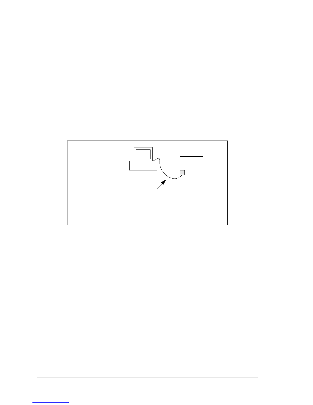
66 Wolf (BL2600)
5.2.2 How to Set Up your Computer’s IP Address for a Direct Connection
When your computer is connected directly to the BL2600 via an Ethernet connection, you
need to assign an IP address to your computer. To assign the PC the address
10.10.6.101 with the subnetmask 255.255.255.0, do the following.
Click on
Start > Settings > Control Panel to bring up the Control Panel, and then
double-click the Network icon. Depending on which version of Windows you are using,
look for the TCP/IP Protocol/Network > Dial-Up Connections/Network line or tab.
Double-click on this line or select Properties or Local Area Connections > Proper ties
to bring up the TCP/IP properties dialog box. You can edit the IP address and the subnet
mask directly. (Disable “obtain an IP address automatically”.) You may want to write
down the existing values in case you have to restore them later. It is not necessary to edit
the gateway address since the gateway is not used with direct connect.
BL2600
User’s PC
Ethernet
crossover
cable
IP 10.10.6.101
Netmask
255.255.255.0
Direct Connection PC to BL2600
Board
Page 71

User’s Manual 67
5.2.3 Run the PINGME.C Demo
Connect the crossover cable from your computer’s Ethernet port to the BL2600’s RJ-45
Ethernet connector. Open this sample program from the SAMPLES\TCPIP\ICMP folder,
compile the program, and start it running under Dynamic C. When the program starts running, the green LNK light on the BL2600 should be on to indicate an Ethernet connection
is made. (Note: If the
LNK light does not light, you may not have a crossover cable, or if
you are using a hub perhaps the power is off on the hub.)
The next step is to ping the board from your PC. This can be done by bringing up the MS-
DOS window and running the ping program:
ping 10.10.6.100
or by Start > Run
and typing the command
ping 10.10.6.100
Notice that the orange ACT light flashes on the BL2600 while the ping is taking place, and
indicates the transfer of data. The ping routine will ping the board four times and write a
summary message on the screen describing the operation.
Page 72

68 Wolf (BL2600)
5.2.4 Running More Demo Programs With a Direct Connection
The program SSI.C (SAMPLES\BL2600\TCPIP\) demonstrates how to make the
BL2600 a Web server. This program allows you to turn the LEDs on an attached Demonstration Board from the Tool Kit on and off from a remote Web browser. The LEDs on the
Demonstration Board match the ones on the Web page. Follow the instructions included
with the sample program. As long as you have not modified the
TCPCONFIG 1 macro in
the sample program, enter the following server address in your Web browser to bring up
the Web page served by the sample program.
http://10.10.6.100.
Otherwise use the TCP/IP settings you entered in the
TCP_CONFIG.LIB library.
The sample program
SMTP.C (SAMPLES\BL2600\TCPIP\) allows you to send an E-mail
when a switch on the Demonstration Board is pressed. Follow the instructions included
with the sample program.
The sample program
TELNET.C (SAMPLES\BL2600\TCPIP\) allows you to communi-
cate with the BL2600 using the Telnet protocol. This program takes anything that comes
in on a port and sends it out Serial P ort C. It uses a digital i nput to in dicate that the TCP/IP
connection should be closed and a digital output to toggle a LED to indicate that there is
an active connection.
Follow the instructions included with the sample program. Run the Telnet program on
your PC (Start > Run telnet 10.10.6.100). As long as you have not modified the
TCPCONFIG 1 macro in the sample program, the IP address is 10.10.6.100 as shown;
otherwise use the TCP/IP settings you entered in the TCP_CONFIG.LIB library. Each
character you type will be printed in Dynamic C's STDIO window, indicating that the
board is receiving the characters typed via TCP/IP.
5.3 Where Do I Go From Here?
NOTE: If you purchased your BL2600 through a distributor or Z-World partner, contact
the distributor or Z-World partner first for technical support.
If there are any problems at this point:
• Check the Z-W orld Technical Bulletin Board at www .zworld.com/support/bb/.
• Use the Technical Support e-mail form at www.zworld.com/support/.
If the sample programs ran fine, you are now ready to go on.
Additional sample programs are described in the Dynamic C TCP/IP User’s Manual.
Refer to the Dynamic C TCP/IP User’s Manual to develop your own applications. An
Introduction to TCP/IP provides background information on TCP/IP, and is available on
Z-World’s Web site.
Page 73

User’s Manual 69
APPENDIX A. SPECIFICATIONS
Appendix A provides the specifications for the BL2600 and
describes the conformal coating.
Page 74
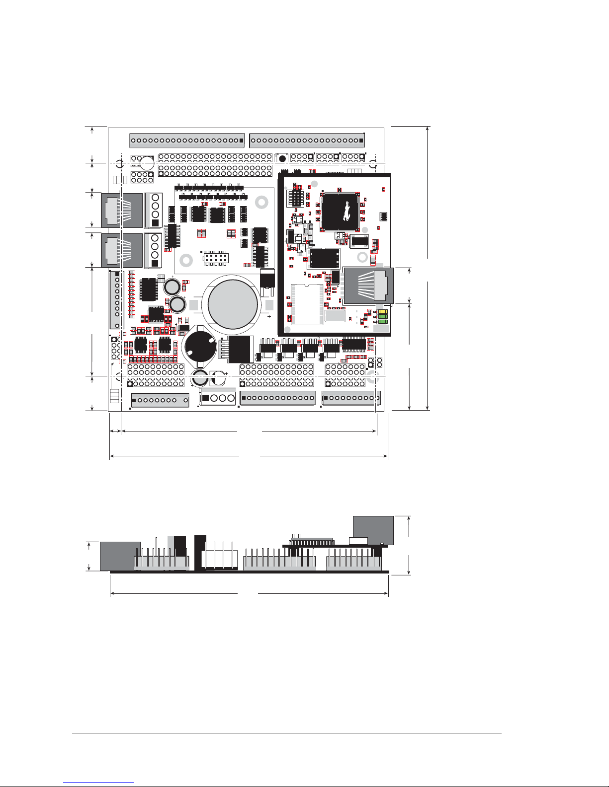
70 Wolf (BL2600)
A.1 Electrical and Mechanical Specifications
Figure A-1 shows the mechanical dimensions for the BL2600.
Figure A-1. BL2600 Dimensions
NOTE: All measurements are in inches followed by millimeters enclosed in parentheses.
J15
J16
AIN0
AIN1
AIN2
AIN3
JP6
420 mA
AV0 AV1 AV2 AV3 AI0 AI1 AI2 AI3 AGND
GND HOUT0 +HK1 GND HOUT2 +HK3 GND
+HK0 GND HOUT1 +HK2 GND HOUT3
TXC TXF TXE 485 GND
GND RXC RXF RXE 485+
J17
GND HOUT0 +HK1 GND HOUT2 +HK3 GND
+HK0 GND HOUT1 +HK2 GND HOUT3
TXC TXF TXE 485
AIN1 AIN3 AIN5 AIN7 AGND AV1 AV3 AI1 AI3 AGND
AIN0 AIN2 AIN4 AIN6 AGND AV0 AV2 AI0 AI2 AGND
J11
20
19
R43
JP6
R44
R39
R38
R20
R33
R34
U13
R22
R21
R17
C18
C19
U12
R15
C13
R16
C10
R10
U11
J8
R14 R13 C11
AIN0 AIN1 AIN2 AIN3 AIN4 AIN5 AIN6 AIN7 AGND
C12 R12 R11
U10
BT1
C26
C27
D1
U15
C25
J12
J13
C22
R55
R42
C23
C24
R41
R40
R35
R36
R37
U14
R26
R28
R30
R19
R29
R32
R31
R56
R57
L1
R27R25
R23
R24
C20
C21
R18
C16
1
2
25
26
RXE
J14
Q19
D3
Q17D2Q18
RXC
D4
Q20
C34
RXF
485+
C35 C36 C37
JP7
485 TERM.
RESISTOR
C30
R58
R59
R60
U18
C32
C33
RCM2
U17
C31
R9
U16
R8
J10
R7
GND/EGND
RP5
RP6
U2
C4
R5
C5
R6
C6
U4
JA
RCM1
RCM3000 ETHERNET CORE MODULE
U3
RP17 RP18
34
33
16
15
1
2
1
2
15
16
33
34
C1
U1
RP3
RP4
GND
+K
DCIN
+5V
JP3,
JP4
AND
JP4
JP1 AND JP2
GND
+K
DCIN
+5V
J4 RABBITNET 1
J6 RABBITNET 0
J7
C14
C17
C15
C78
J9
C9
U9
RP16
C8
U8
R4
R3
RP15
RP14
RP12
RP13
RP11
R1
R2
C7
U6
U7
U5
RP8
RP7
RP9
RP10
C2
Q9
Q10
J5
Q12
Q15Q14 Q16
Q11
Q13
C3
Q1 Q2 Q3 Q4 Q5 Q6 Q7 Q8
JP2
JP1
J1
J2
GND DIN28 DIN24 DIN20 DIN16 GND DIO12 DIO08 DIO04 DIO00
DIN30 DIN26 DIN22 DIN18 +K DIO14 DIO10 DIO06 DIO02 GND
DIN31 DIN27 DIN23 DIN19 +K DIO15 DIO11 DIO07 DIO03 GND
GND DIN29 DIN25 DIN21 DIN17 GND DIO13 DIO09 DIO05 DIO01
GND DIO14 DIO12 DIO10 DIO08 DIO06 DIO04 DIO02 DIO00 GND
+K DIO15 DIO13 DIO11 DIO09 DIO07 DIO05 DIO03 DIO01 GND
GND DIN30 DIN28 DIN26 DIN24 GND DIN22 DIN20 DIN18 DIN16
DIN31 DIN29 DIN27 DIN25 +K DIN23 DIN21 DIN19 DIN17 GND
DIO 0007 PULLS
DIO 0815 PULLS
1
2
39
40
SW1
J3
1
2
DCIN DCIN GND GND
R111
R112
RESET
RP2
RP1
JP3
DIN 1619 PULLS
JP4
DIN 2023 PULLS
DIN 2431 PULLS
JP5
R84
C28
1
2
DS1
U1
U6
R28
R38
R41
C5
C3
C9
C8
C12
C17
C23
C30
C18
C29
C35
C33
R29
R37
R39
R40
R42
Y3
C42R35
R31
R27
R25
DS1
R67
R70
J4
C79
Y4
C83
C86
GND
R75
R74
R71
DS3
DS2
R63 R64
C71
C72
C68
C64
C67
L2
U8
R49
R48
C62
R51
C61
R44
R47
C59
C49
C57
L1
R69
R72
R73
C75
C74
R58
C53
C47
C48
C45
C44
C43
JP5
C31
JP3
JP4
C28
C27
C37
C36
C32
R24
R22
C19
R23
C24
R20
C20
R19
C16
C15
R17
R18
R7
R9
R1
R8
C1
R10
R14
C4
SPD LNK ACT
J3
U5
U4
D1
Q1
C39
RP1
4.96
(126)
4.85
(123)
4.45
(113)
RJ-45 jacks extend
0.16" (4.0 mm)
past edge of
board
0.20
(5.1)
0.605
(15.4)
4.85
(123)
1.00
(25)
0.625
(15.7)
1.83
(46.5)
0.635
(16.1)
0.60
(15.2)
0.60
(15.2)
1.905
(48.4)
0.515
(13.1)
0.49
(12)
Page 75

User’s Manual 71
Table A-1 lists the electrical, mechanical, and environmental specifications for the BL2600.
Table A-1. BL2600 Specificat ions
Feature BL2600 BL2610
Microprocessor
Rabbit 3000
®
at 44.2 MHz Rabbit 3000® at 29.4 MHz
Ethernet Port 10/100Base-T, 3 LEDs None
Flash Memory 512K (standard)
Program Execution SRAM
512K
*
Data SRAM 256K —
Backup Battery
Panasonic CR2477 or equivalent 3 V lithium coin type,
950 mA·h standard, socket-mounted
Configurable I/O
16 individually software-configurable I/O channels may be configured
as digital inputs ± 36 V DC, switching threshold 1.5 V typical,
or as sinking digital outputs up to 40 V, 200 mA each
Digital Inputs
8 inputs hardware-configurable pull-up or pull-down,
± 36 V DC, switching threshold 1.4 V typical
High-Current Digital Outputs
4 outputs individually software-configurable as sinking or sourcing,
+40 V DC, 2 A max. per channel
Analog Inputs
Eight 11-bit res. channels, software-selectable ranges
unipolar: 1, 2, 2.5, 5, 10, 20 V DC; bip olar ± 1, ± 2, ±5, ± 10 V D C :
4 channels can be hardw a re -co nf igur ed f or 4–20 mA;
1 MΩ input impedance, up to 4,100 samples/s
Analog Outputs
Four 12-bit res. channels,
buffered, 0–10 V DC, ±10 VDC, and 4–20 mA,
update rate 12 kHz
Serial Ports
5 serial ports:
• one RS-485 or one RS-232
• two RS-232 or one RS-232 (with CTS/RTS)
• one clocked serial port multiplexed to two RS-422 SPI master ports
• one serial port dedicated for programming/debug
Serial Rate
Max. asynchronous rate = CLK/8,
Max. synchronous rate = CLK/2
Connectors
RJ-45 connectors:
one Ethernet and two RabbitNet™
Friction-lock connectors:
two polarized 9-position terminals with 0.1" pitch
three 4-position power terminals with 0.156" pitch
two 20-position terminals with 0.1" pitch (2 × 20 IDC option)
one 13-position terminal with 0.1" pitch (2 × 13 IDC option)
one 10-position terminal with 0.1" pitch (2 × 7 IDC option)
Programming port:
2 × 5 IDC, 1.27 mm pitch (BL2600),
2 × 5 IDC, 2 mm pitch (BL261 0)
Page 76
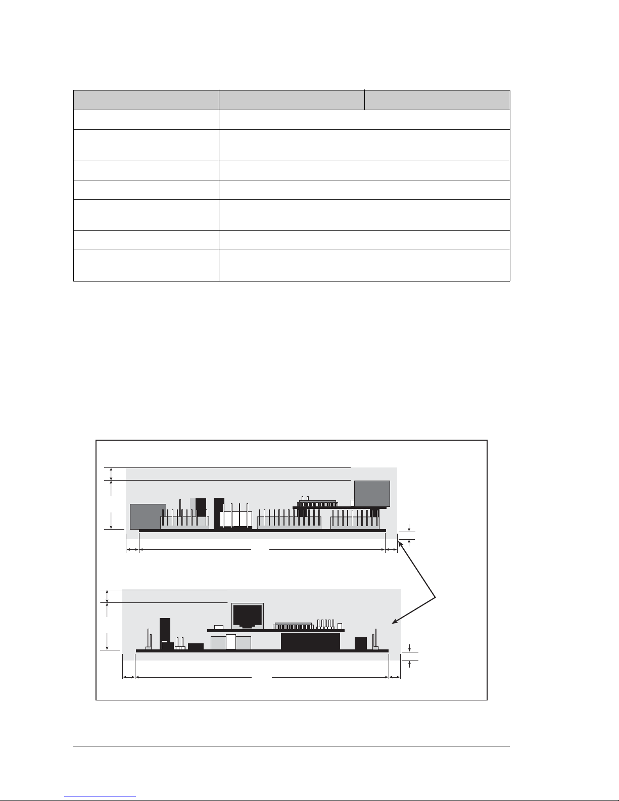
72 Wolf (BL2600)
A.1.1 Exclusion Zone
It is recommended that you allow for an “exclusion zone” of 0.25" (6 mm) around the
BL2600 in all directions when the BL2600 is incorporated into an assembly that includes
other components. This “exclusion zone” that you keep free of other components and
boards will allow for sufficient air flow, and will help to minimize any electrical or EMI
interference between adjacent boards. An “exclusion zone” of 0.12" (3 mm) is recommended below the BL2600. Figure A-2 shows this “exclusion zone.”
Figure A-2. BL2600 “Exclusion Zone”
Real-Time Clock Yes
Timers
T en 8-bit timers (6 cascadable, 3 reser ved for intern al peripherals),
one 10-bit timer with 2 match registers
W atchdog/Supervisor Yes
Power 9–36 V DC, 12 W max.
Operating T emperatu re
–40°C to +70°C
(–40°C to +85°C without battery)
Humidity 5–95%, noncondensing
Board Size
4.85" × 4.96" × 1.00"
(123 mm × 126 mm × 25 mm)
* 256K flash/128K SRAM options available options available for BL2610.
Table A-1. BL2600 Specifications (continued)
Feature BL2600 BL2610
0.12
(3)
0.12
(3)
1.00
(25)
4.85
(123)
4.96
(126)
0.25
(6)
0.25
(6)
0.25
(6)
0.25
(6)
0.25
(6)
1.00
(25)
0.25
(6)
Exclusion
Zone
Page 77
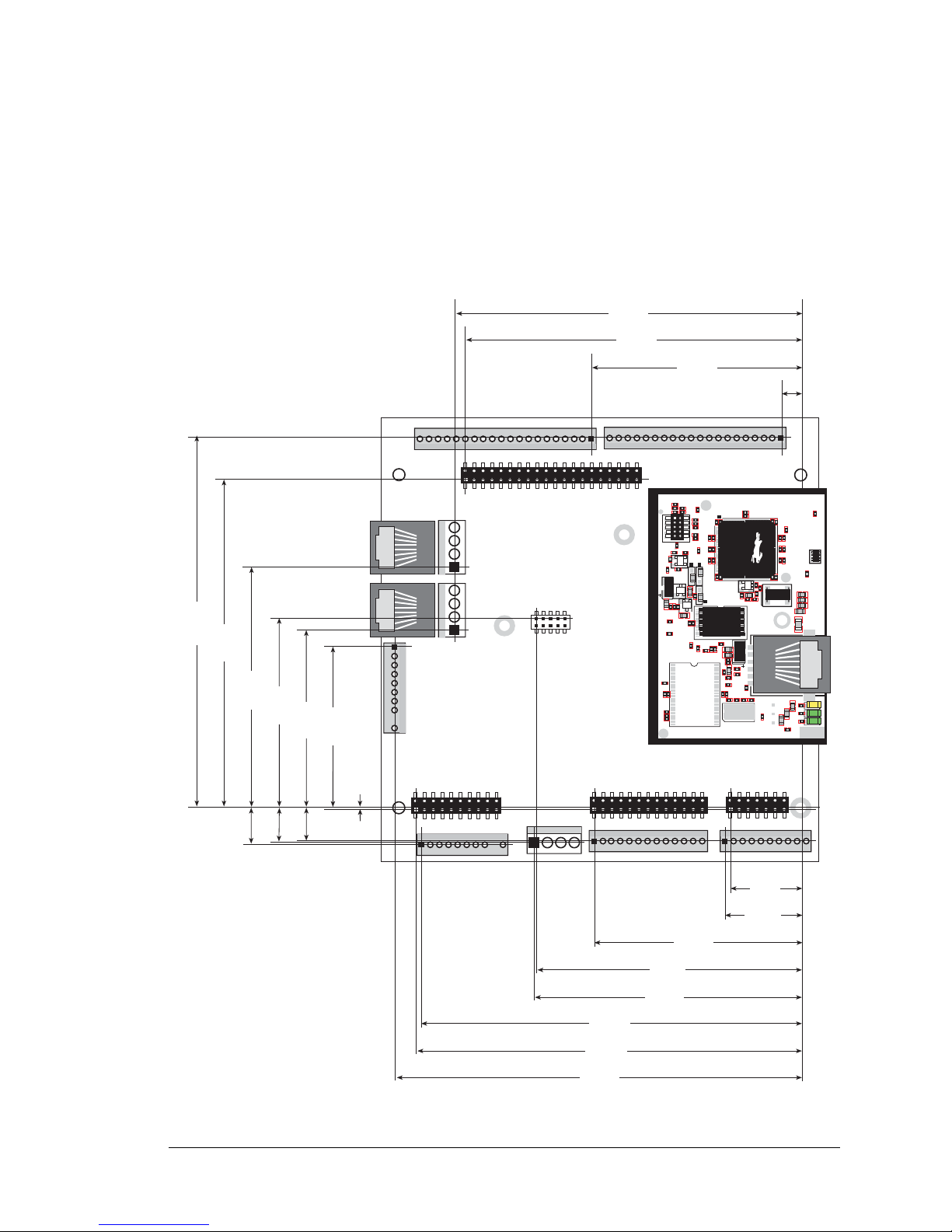
User’s Manual 73
A.1.2 Headers
The BL2600 has 0.1" IDC header sockets or friction-lock connectors at J1, J2, J3, J11,
J13, J14, J15, J16, and J17 for physical connection to other boards or ribbon cables. There
are friction-lock connectors at J5, J7, and J12 for power-supply connections, and at J8.
Figure A-3 shows the BL2600 footprint. These values are relative to one of the mounting
holes.
Figure A-3. User Board Footprint for BL2600
0.025
(0.6)
0.790
(20.1)
0.845
(21.5)
2.290
(58.2)
2.930
(74.4)
2.970
(75.4)
4.195
(106.6)
4.265
(108.3)
4.495
(114.2)
0.375
(9.5)
0.380
(9.7)
0.415
(10.5)
1.785
(45.3)
1.970
(50.0)
2.106
(53.5)
2.670
(67.8)
3.650
(92.7)
4.125
(104.8)
3.835
(97.4)
3.720
(94.5)
2.320
(58.9)
0.220
(5.6)
U1
U6
R28
R38
R41
C5
C3
C9
C8
C12
C17
C23
C30
C18
C29
C35
C33
R29
R37
R39
R40
R42
Y3
C42R35
R31
R27
R25
DS1
R67
R70
J4
C79
Y4
C83
C86
GND
R75
R74
R71
DS3
DS2
R63 R64
C71
C72
C68
C64
C67
L2
U8
R49
R48
C62
R51
C61
R44
R47
C59
C49
C57
L1
R69
R72
R73
C75
C74
R58
C53
C47
C48
C45
C44
C43
JP5
C31
JP3
JP4
C28
C27
C37
C36
C32
R24
R22
C19
R23
C24
R20
C20
R19
C16
C15
R17
R18
R7
R9
R1
R8
C1
R10
R14
C4
SPD LNK ACT
J3
U5
U4
D1
Q1
C39
RP1
J2
J16
J5
J8
J7
J15
J11
J12
J13
J14
J17
J1
J2
J3
J9
Page 78
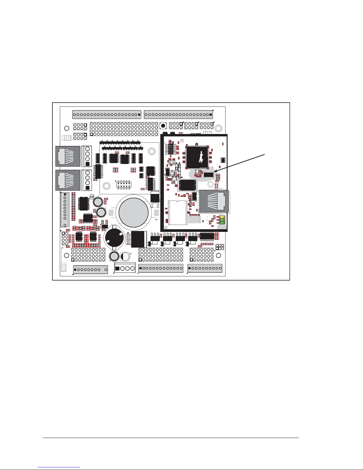
74 Wolf (BL2600)
A.2 Conformal Coating
The areas around the crystal oscillator and the battery backup circuit on the BL2600 module have had the Dow Corning silicone-based 1-2620 conformal coating applied. The conformally coated areas are shown in Figure A-4. The conformal coating protects these
high-impedance circuits from the effects of moisture and contaminants over time.
Figure A-4. BL2600 Areas Receiving Conformal Coating
Any components in the conformally coated area may be replaced using standard soldering
procedures for surface-mounted components. A new conformal coating should then be
applied to offer continuing protection against the effects of moisture and contaminants.
NOTE: For more information on conformal coatings, refer to Rabbit Semiconductor
Technical Note 303, Conformal Coatings.
J15
J16
AIN0
AIN1
AIN2
AIN3
JP6
420 mA
AV0 AV1 AV2 AV3 AI0 AI1 AI2 AI3 AGND
GND HOUT0 +HK1 GND HOUT2 +HK3 GND
+HK0 GND HOUT1 +HK2 GND HOUT3
TXC TXF TXE 485 GND
GND RXC RXF RXE 485+
J17
GND HOUT0 +HK1 GND HOUT2 +HK3 GND
+HK0 GND HOUT1 +HK2 GND HOUT3
TXC TXF TXE 485
AIN1 AIN3 AIN5 AIN7 AGND AV1 AV3 AI1 AI3 AGND
AIN0 AIN2 AIN4 AIN6 AGND AV0 AV2 AI0 AI2 AGND
J11
20
19
R43
JP6
R44
R39
R38
R20
R33
R34
U13
R22
R21
R17
C18
C19
U12
R15
C13
R16
C10
R10
U11
J8
R14 R13 C11
AIN0 AIN1 AIN2 AIN3 AIN4 AIN5 AIN6 AIN7 AGND
C12 R12 R11
U10
BT1
C26
C27
D1
U15
C25
J12
J13
C22
R55
R42
C23
C24
R41
R40
R35
R36
R37
U14
R26
R28
R30
R19
R29
R32
R31
R56
R57
L1
R27R25
R23
R24
C20
C21
R18
C16
1
2
25
26
RXE
J14
Q19
D3
Q17D2Q18
RXC
D4
Q20
C34
RXF
485+
C35 C36 C37
JP7
485 TERM.
RESISTOR
C30
R58
R59
R60
U18
C32
C33
RCM2
U17
C31
R9
U16
R8
J10
R7
GND/EGND
RP5
RP6
U2
C4
R5
C5
R6
C6
U4
JA
RCM1
RCM3000 ETHERNET CORE MODULE
U3
RP17 RP18
34
33
16
15
1
2
1
2
15
16
33
34
C1
U1
RP3
RP4
GND
+K
DCIN
+5V
JP3,
JP4
AND
JP4
JP1 AND JP2
GND
+K
DCIN
+5V
J4 RABBITNET 1
J6 RABBITNET 0
J7
C14
C17
C15
C78
J9
C9
U9
RP16
C8
U8
R4
R3
RP15
RP14
RP12
RP13
RP11
R1
R2
C7
U6
U7
U5
RP8
RP7
RP9
RP10
C2
Q9
Q10
J5
Q12
Q15Q14 Q16
Q11
Q13
C3
Q1 Q2 Q3 Q4 Q5 Q6 Q7 Q8
JP2
JP1
J1
J2
GND DIN28 DIN24 DIN20 DIN16 GND DIO12 DIO08 DIO04 DIO00
DIN30 DIN26 DIN22 DIN18 +K DIO14 DIO10 DIO06 DIO02 GND
DIN31 DIN27 DIN23 DIN19 +K DIO15 DIO11 DIO07 DIO03 GND
GND DIN29 DIN25 DIN21 DIN17 GND DIO13 DIO09 DIO05 DIO01
GND DIO14 DIO12 DIO10 DIO08 DIO06 DIO04 DIO02 DIO00 GND
+K DIO15 DIO13 DIO11 DIO09 DIO07 DIO05 DIO03 DIO01 GND
GND DIN30 DIN28 DIN26 DIN24 GND DIN22 DIN20 DIN18 DIN16
DIN31 DIN29 DIN27 DIN25 +K DIN23 DIN21 DIN19 DIN17 GND
DIO 0007 PULLS
DIO 0815 PULLS
1
2
39
40
SW1
J3
1
2
DCIN DCIN GND GND
R111
R112
RESET
RP2
RP1
JP3
DIN 1619 PULLS
JP4
DIN 2023 PULLS
DIN 2431 PULLS
JP5
R84
C28
1
2
DS1
U1
U6
R28
R38
R41
C5
C3
C9
C8
C12
C17
C23
C30
C18
C29
C35
C33
R29
R37
R39
R40
R42
Y3
C42R35
R31
R27
R25
DS1
R67
R70
J4
C79
Y4
C83
C86
GND
R75
R74
R71
DS3
DS2
R63 R64
C71
C72
C68
C64
C67
L2
U8
R49
R48
C62
R51
C61
R44
R47
C59
C49
C57
L1
R69
R72
R73
C75
C74
R58
C53
C47
C48
C45
C44
C43
JP5
C31
JP3
JP4
C28
C27
C37
C36
C32
R24
R22
C19
R23
C24
R20
C20
R19
C16
C15
R17
R18
R7
R9
R1
R8
C1
R10
R14
C4
SPD LNK ACT
J3
U5
Conformally
coated area
U4
D1
Q1
C39
RP1
Page 79
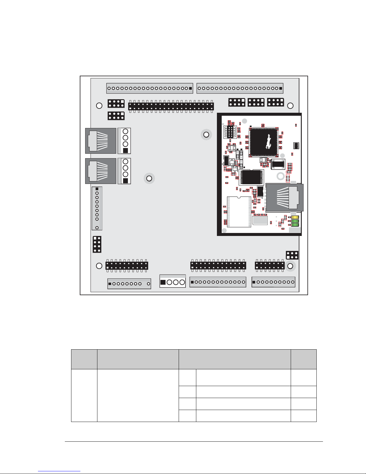
User’s Manual 75
A.3 Jumper Configurations
Figure A-5 shows the header locations used to configure the various BL2600 options via jumpers.
Figure A-5. Location of BL2600 Configurable Positions
Table A-2 lists the configuration options.
Table A-2. BL2600 Jumper Configurations
Header Description Pins Connected
Factory
Default
JP1 DIO00–DIO07
1–2 Inputs pulled up to +5 V
×
3–5 Inputs pulled up to DCIN
5–6 Inputs pulled up to +K
5–7 Inputs pulled down to GND
JP6
JP2
JP1
JP3
JP4
JP5
JP7
U1
U6
R28
R38
R41
C5
C3
C9
C8
C12
C17
C23
C30
C18
C29
C35
C33
R29
R37
R39
R40
R42
Y3
C42R35
R31
R27
R25
DS1
R67
R70
J4
C79
Y4
C83
C86
GND
R75
R74
R71
DS3
DS2
R63 R64
C71
C72
C68
C64
C67
L2
U8
R49
R48
C62
R51
C61
R44
R47
C59
C49
C57
L1
R69
R72
R73
C75
C74
R58
C53
C47
C48
C45
C44
C43
JP5
C31
JP3
JP4
C28
C27
C37
C36
C32
R24
R22
C19
R23
C24
R20
C20
R19
C16
C15
R17
R18
R7
R9
R1
R8
C1
R10
R14
C4
SPD LNK ACT
J3
U5
U4
D1
Q1
C39
RP1
Page 80
76 Wolf (BL2600)
JP2 DIO08–DIO15
1–2 Inputs pulled up to +5 V
×
3–4 Inputs pulled up to DCIN
5–6 Inputs pulled up to +K
7–8 Inputs pulled down to GND
JP3 DIN16–DIN19
1–2 Inputs pulled up to +5 V
×
3–4 Inputs pulled up to DCIN
5–6 Inputs pulled up to +K
7–8 Inputs pulled down to GND
JP4 DIN20–DIN23
1–2 Inputs pulled up to +5 V
×
3–4 Inputs pulled up to DCIN
5–6 Inputs pulled up to +K
7–8
Inputs pulled down to GND
(needed for these to be PWM outputs)
JP5 DIN24–DIN31
1–2 Inputs pulled up to +5 V
×
3–4 Inputs pulled up to DCIN
5–6 Inputs pulled up to +K
7–8 Inputs pulled down to GND
JP6
A/D Converter Voltage/Current
Measurement Options
None Voltage Option
×
1–2 AIN0 4–20 mA option
3–4 AIN1 4–20 mA option
5–6 AIN2 4–20 mA option
7–8 AIN3 4–20 mA option
JP7
RS-485 Bias and Termination
Resistors
1–2
5–6
Bias and termination resistors
connected
×
1–3
4–6
Bias and termination resistors not
connected
*
* Although pins 1–3 and 4–6 of header JP7 are shown “jumpered” for the termination and
bias resistors not connected, pins 3 and 4 are not actually connected to anything, and this
configuration is a “parking” configuration for the jumpers so that they will be readily available should you need to enable the termination and bias resistors in the future.
Table A-2. BL2600 Jumper Configurations
Header Description Pins Connected
Factory
Default
Page 81
User’s Manual 77
A.4 Use of Rabbit 3000 Parallel Ports
Figure A-6 shows the Rabbit 3000 parallel ports.
Figure A-6. BL2600 Rabbit-Based Subsystems
Table A-3 lists the Rabbit 3000 parallel ports and their use in the BL2600.
Table A-3. Use of Rabbit 3000 Parallel Ports
Port I/O Signal Initial State
PA0–PA7 I/O ID0–ID7
Pulled up
PB0–PB1 Input Not connected
Pulled up
PB2–PB4 Output IA0–IA2
High
PB5–PB7 Output Not connected High
PC0 Output TXD SPI
Serial Port D
Inactive high
PC1 Input RXD SPI Pulled up
PC2 Output TXC RS-232
Serial Port C
Inactive high
PC3 Input RXC RS-232 Pulled up
PC4 Output Not connected Inactive high
PC5 Input Not connected Pulled up
PC6 Output TXA Programming Port
Serial Port A
Low
PC7 Input RXA Programming Port Pulled up
R
ABBIT
3000
Port A
Port B
Port D
(+Ethernet Port)
PA0PA7
PB2PB4
PE0PE3
PD0PD1
PD4PD5
/RESET,
/IOWR,
STATUS
SMODE0
SMODE1
Watchdog
11 Timers
Clock Doubler
Slave Port
Real-Time Clock
RAM
Backup Battery
Support
Flash
Port C
(Serial Ports B,C & D)
Programming
Port
(Serial Port A)
Ethernet
Port
4 Ethernet signals
PC6
PC7, /RES
PC0, PC2, PC4
PC1, PC3, PC5
Port G
(Serial Ports E & F)
PG2, PG6
PG3, PG7
Port F
PF0
PG0, PG1,
PG4
Port G
(+Serial Ports)
Misc. I/O
/RES_IN
/IORD
PE4PE5
PF1PF7
Port E
(+Ethernet Port)
Page 82
78 Wolf (BL2600)
NOTE: The Ethernet signals are configured as follows according to which RabbitCore
module is used with the BL2600.
• ENET indicates that this port is initialized by the Ethernet driver.
• OUT indicates that this port is set to be an output and is set to a logic low.
PD0–PD1 Output Ethernet See Note
PD2–PD3 Output Not connected Low
PD4 Output Load D/A converter data Low
PD5 Output RS-485/RS-232 select Low
PD6–PD7 Output Not connected Low
PE0 Output Ethernet See Note
PE1 Outp ut /CS strobe (digital I/O enable) Inactive high
PE2 Output Ethernet See Note
PE3 Output RS-485 transmit control Low
PE4–PE5 Input IN00-IN01
Pulled up
PE6–PE7 Output Not connected Low
PF0 Output Serial CLKD Low
PF1 Input A/D converter busy Pulled up
PF2–PF7 Input IN02–IN07 Pulled up
PG0 Output EEPROM CLK —
PG1 Output EEPROM data Pulled up
PG2 Output TXF RS-232
Serial Port F
Inactive high
PG3 Input RXF RS-232 Pulled up
PG4 Output /CS (digital output enable) Low
PG5 Output Not connected Low
PG6 Output TXE RS-232
Serial Port E
Inactive high
PG7 Input RXE RS-232 Pulled up
Port BL2600 BL2610
PD0 ENET OUT
PD1 OUT OUT
PE0 ENET OUT
PE2 ENET OUT
Table A-3. Use of Rabbit 3000 Parallel Ports (continued)
Port I/O Signal Initial State
Page 83
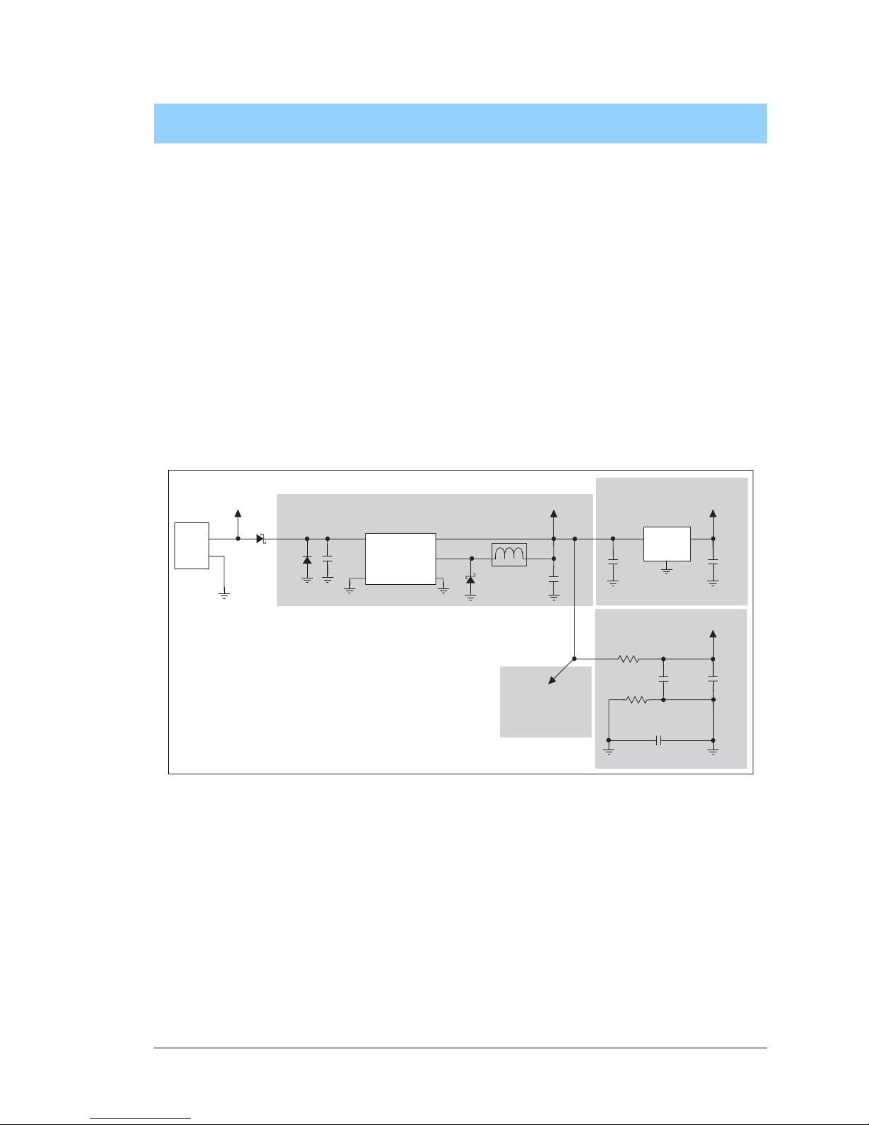
User’s Manual 79
APPENDIX B. POWER SUPPLY
Appendix B describes the power circuitry provided on the
BL2600.
B.1 Power Supplies
Power is supplied to the BL2600 via the friction-lock connector at J12. The BL2600 is
protected against reverse polarity by a diode at D1 as shown in Figure B-1.
Figure B-1. BL2600 Power Supply
The input voltage range is from 9 V to 36 V. A switching power regulator is used to provide +5 V for the BL2600 logic circuits. In turn, the regulated +5 V DC power supply is
used to drive a regulated +3.3 V power supply and ±12 V power supplies used by the opamps driving the digital outputs.
The digital ground and the analog ground share a single split ground plane on the board,
with the analog ground connected at a single point to the digital ground by a 0 Ω resistor
(R57). This is done to minimize digital noise in the analog circuits and to eliminate the
possibility of ground loops. External connections to analog ground are made on a polarized friction-lock connector at J8.
LINEAR POWER
REGULATOR
POWER
IN
J12
C44
10 µF
LM1117T
U10
+3.3 V
3
1
2
1
4
1B220
D41
47 µF
C22
330 µF
+5 V
L1
C25
330 µH
D42
B220
SWITCHING POWER REGULATOR
U15
LM2576
RAW
1
4
2
C44
10 µF
TVS1
C78
0.1 µF
C23
0.1 µF
C24
10 µF
R56
4.7 W
R57
0 W
+5 V
ANALOG POWER
SUPPLY
AGNDGND
±12 V
POWER
SUPPLIES
Page 84
80 Wolf (BL2600)
B.1.1 Power for Analog Circuits
Power to the analog circuits is provided by way of a one-stage low-pass filter, which
isolates the analog section from digital noise generated by the other components. The analog +5 V supply powers the D/A converter, and is not accessible to the user. The A/D converter is powered by the regulated +3.3 V supply, and supplies the +2.048 V reference
violate from which the 1.667 V and 2.5 V reference voltages for the D/A converter output
circuits are derived.
B.2 Batteries and External Battery Connections
The SRAM and the real-time clock on the BL2600 module have battery backup. Power to
the SRAM and the real- time clock (VRAM) is provided by two different source s, depending
on whether the main part of the BL2600 is powered or not. When the BL2600 is powered
normally, and the +3.3 V supply is within operating limits, the SRAM and the real-time
clock are powered from the +3.3 V supply. If power to the board is lost or falls below 2.93 V
(2.63 V on the BL2610), the VRAM and real-time clock power will come from the battery.
The reset generator circuit c ontrols t he source of power by way of its
/RESET output signal.
A replaceable 950 mA·h lithium battery provides power to the real-time clock and SRAM
when external power is removed from the circuit board. The drain on the battery is typically
less than 10 µA when there is no external power applied to the BL2600, and so the expected
shelf life of the battery is
This is almost as long as the 10-year shelf life of the battery.
B.2.1 Replacing the Backup Battery
The battery is user-replaceable, and is fitted in a battery holder. To replace the battery, lift
up on the spring clip and slide out the old battery. Use only a Panasonic CR2477 or equivalent replacement battery, and insert it into the battery holder with the + side facing up.
NOTE: The SRAM contents and the real-time clock settings will be lost if the battery is
replaced with no power applied to the BL2600. Exercise care if you replace the battery
while external power is applied to the BL2600.
CAUTION: There is an explosion danger if th e bat te ry is short-circuited, r echarged,
or replaced incorrectly. Replace the battery only with the same type or an equivalent
type recommended by the battery manufacturer. Dispose of used batteries according
to the battery manufacturer’s instructions.
950 mA·h
12 µA
------------------------ 9.0 years.=
Page 85

User’s Manual 81
APPENDIX C.
D
EMONSTRATION BOARD
Appendix C shows how to connect the Demon stration Board to
the BL2600.
C.1 Connecting Demonstration Board
Before running sample programs based on the Demonstration Board, you will have to connect the Demonstration Board
from the BL2600 Tool Kit to the BL2600 board. Proceed as
follows.
1. Use the wires included in the
BL2600 Tool
Kit to connect header J1 on the Demonstra-
tion
Board to screw-terminal headers J1 and J12 on the BL2600. The connections are
shown in Figure C-1
for sample program DIGIN.C and for sample program SMTP.C, in
Figure C-2
for sample program DIGOUT.C and for sample program SSI.C, and in
Figure C-3
for sample program HIGH_CURRENT_IO.C.
2. Make sure that your BL2600 is connected to your PC via the programming cable and
that the power supply is connected to the BL2600 and plugged in as described in
Chapter 2, “Getting Started.”
Page 86
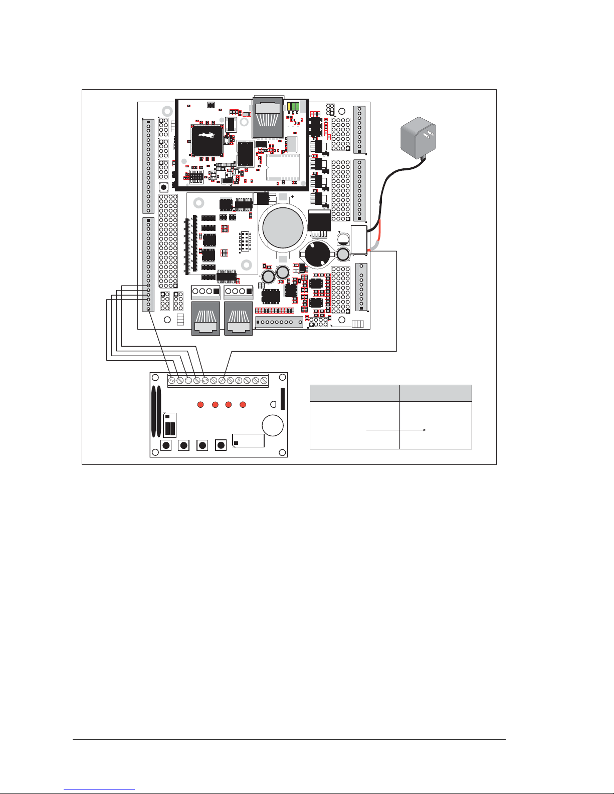
82 Wolf (BL2600)
Figure C-1. General Digital Input Connections Between BL2600 and Demonstration Board
J1
J15
J16
AIN0
AIN1
AIN2
AIN3
JP6
420 mA
AV0 AV1 AV2 AV3 AI0 AI1 AI2 AI3 AGND
GND HOUT0 +HK1 GND HOUT2 +HK3 GND
+HK0 GND HOUT1 +HK2 GND HOUT3
TXC TXF TXE 485 GND
GND RXC RXF RXE 485+
J17
GND HOUT0 +HK1 GND HOUT2 +HK3 GND
+HK0 GND HOUT1 +HK2 GND HOUT3
TXC TXF TXE 485
AIN1 AIN3 AIN5 AIN7 AGND AV1 AV3 AI1 AI3 AGND
AIN0 AIN2 AIN4 AIN6 AGND AV0 AV2 AI0 AI2 AGND
J11
20
19
R43
JP6
R44
R39
R38
R20
R33
R34
U13
R22
R21
R17
C18
C19
U12
R15
C13
R16
C10
R10
U11
J8
R14 R13 C11
AIN0 AIN1 AIN2 AIN3 AIN4 AIN5 AIN6 AIN7 AGND
C12 R12 R11
U10
BT1
C26
C27
D1
U15
C25
J12
J13
C22
R55
R42
C23
C24
R41
R40
R35
R36
R37
U14
R26
R28
R30
R19
R29
R32
R31
R56
R57
L1
R27R25
R23
R24
C20
C21
R18
C16
1
2
25
26
RXE
J14
Q19
D3
Q17
D2
Q18
RXC
D4
Q20
C34
RXF
485+
C35 C36 C37
JP7
485 TERM.
RESISTOR
C30
R58
R59
R60
U18
C32
C33
RCM2
U17
C31
R9
U16
R8
J10
R7
GND/EGND
RP5
RP6
U2
C4
R5
C5
R6
C6
U4
JA
RCM1
RCM3000 ETHERNET CORE MODULE
U3
RP17 RP18
34
33
16
15
1
2
1
2
15
16
33
34
C1
U1
RP3
RP4
GND
+K
DCIN
+5V
JP3,
JP4
AND
JP4
JP1 AND JP2
GND
+K
DCIN
+5V
J4 RABBITNET 1
J6 RABBITNET 0
J7
C14
C17
C15
C78
J9
C9
U9
RP16
C8
U8
R4
R3
RP15
RP14
RP12
RP13
RP11
R1
R2
C7
U6
U7
U5
RP8
RP7
RP9
RP10
C2
Q9
Q10
J5
Q12
Q15Q14 Q16
Q11
Q13
C3
Q1 Q2 Q3 Q4 Q5 Q6 Q7 Q8
JP2
JP1
J1
J2
GND DIN28 DIN24 DIN20 DIN16 GND DIO12 DIO08 DIO04 DIO00
DIN30 DIN26 DIN22 DIN18 +K DIO14 DIO10 DIO06 DIO02 GND
DIN31 DIN27 DIN23 DIN19 +K DIO15 DIO11 DIO07 DIO03 GND
GND DIN29 DIN25 DIN21 DIN17 GND DIO13 DIO09 DIO05 DIO01
GND DIO14 DIO12 DIO10 DIO08 DIO06 DIO04 DIO02 DIO00 GND
+K DIO15 DIO13 DIO11 DIO09 DIO07 DIO05 DIO03 DIO01 GND
GND DIN30 DIN28 DIN26 DIN24 GND DIN22 DIN20 DIN18 DIN16
DIN31 DIN29 DIN27 DIN25 +K DIN23 DIN21 DIN19 DIN17 GND
DIO 0007 PULLS
DIO 0815 PULLS
1
2
39
40
SW1
J3
1
2
DCIN DCIN GND GND
R111
R112
RESET
RP2
RP1
JP3
DIN 1619 PULLS
JP4
DIN 2023 PULLS
DIN 2431 PULLS
JP5
R84
C28
1
2
DS1
BL2600
Jumpers:
H1: None
H2: As shown
·
BUZZER
·
LED4
·
LED3
·
LED2
·
LED1
· K·
+5V
·
SW4
·
SW3
·
SW2
·
SW1
·
GND
BUZZER
H1
J1
H2
· · 1-2
· · 3-4
· · 5-6
LED1 LED2 LED3 LED4
SW1 SW2 SW3 SW4
· · 8-7
· · 6-5
· ·
4-3
· · 2-1
DEMO BOARD
BL2600
(Header J1)
+DCIN (J12)
GND
DIO00
DIO01
DIO02
DIO03
Demonstration Board
(Header J1)
K
GND
SW1
SW2
SW3
SW4
J12
U1
U6
R28
R38
R41
C5
C3
C9
C8
C12
C17
C23
C30
C18
C29
C35
C33
R29
R37
R39
R40
R42
Y3
C42R35
R31
R27
R25
DS1
R67
R70
J4
C79
Y4
C83
C86
GND
R75
R74
R71
DS3
DS2
R63 R64
C71
C72
C68
C64
C67
L2
U8
R49
R48
C62
R51
C61
R44
R47
C59
C49
C57
L1
R69
R72
R73
C75
C74
R58
C53
C47
C48
C45
C44
C43
JP5
C31
JP3
JP4
C28
C27
C37
C36
C32
R24
R22
C19
R23
C24
R20
C20
R19
C16
C15
R17
R18
R7
R9
R1
R8
C1
R10
R14
C4
SPD LNK ACT
J3
U5
U4
D1
Q1
C39
RP1
+
Page 87
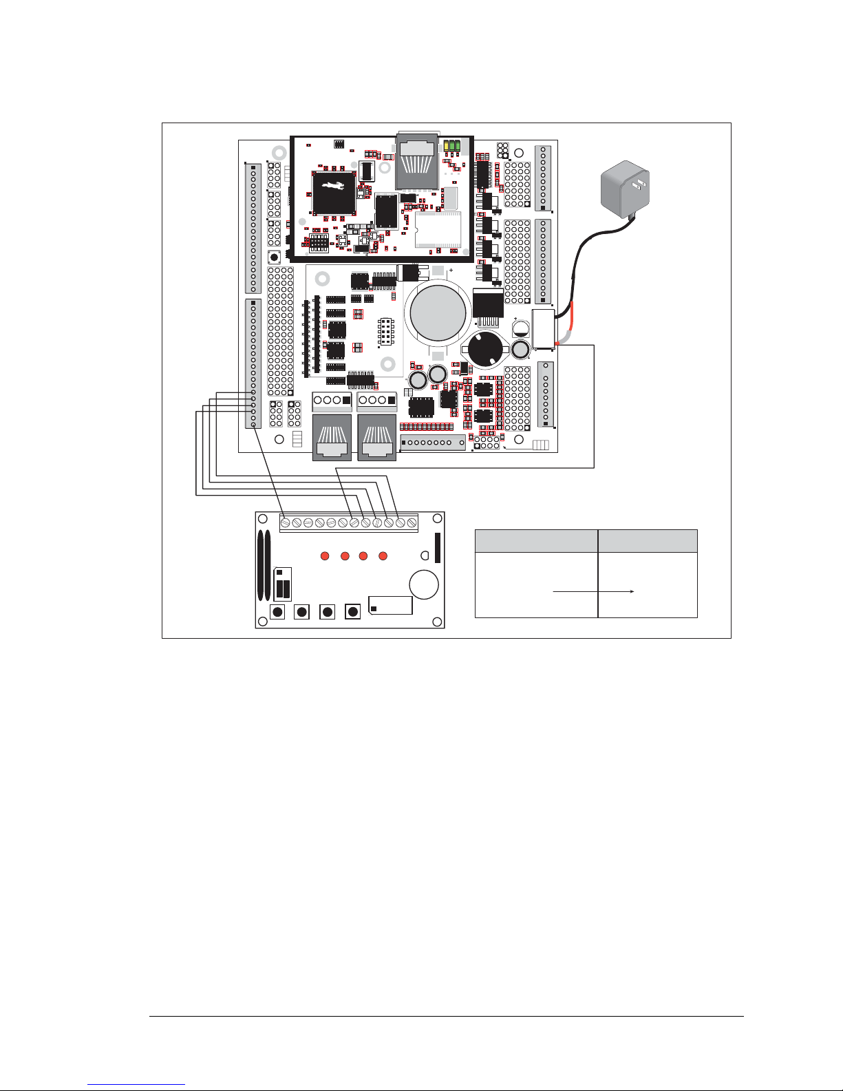
User’s Manual 83
Figure C-2. Digital Output Connections Between BL2600 and Demonstration Board
J1
J15
J16
AIN0
AIN1
AIN2
AIN3
JP6
420 mA
AV0 AV1 AV2 AV3 AI0 AI1 AI2 AI3 AGND
GND HOUT0 +HK1 GND HOUT2 +HK3 GND
+HK0 GND HOUT1 +HK2 GND HOUT3
TXC TXF TXE 485 GND
GND RXC RXF RXE 485+
J17
GND HOUT0 +HK1 GND HOUT2 +HK3 GND
+HK0 GND HOUT1 +HK2 GND HOUT3
TXC TXF TXE 485
AIN1 AIN3 AIN5 AIN7 AGND AV1 AV3 AI1 AI3 AGND
AIN0 AIN2 AIN4 AIN6 AGND AV0 AV2 AI0 AI2 AGND
J11
20
19
R43
JP6
R44
R39
R38
R20
R33
R34
U13
R22
R21
R17
C18
C19
U12
R15
C13
R16
C10
R10
U11
J8
R14 R13 C11
AIN0 AIN1 AIN2 AIN3 AIN4 AIN5 AIN6 AIN7 AGND
C12 R12 R11
U10
BT1
C26
C27
D1
U15
C25
J12
J13
C22
R55
R42
C23
C24
R41
R40
R35
R36
R37
U14
R26
R28
R30
R19
R29
R32
R31
R56
R57
L1
R27R25
R23
R24
C20
C21
R18
C16
1
2
25
26
RXE
J14
Q19
D3
Q17
D2
Q18
RXC
D4
Q20
C34
RXF
485+
C35 C36 C37
JP7
485 TERM.
RESISTOR
C30
R58
R59
R60
U18
C32
C33
RCM2
U17
C31
R9
U16
R8
J10
R7
GND/EGND
RP5
RP6
U2
C4
R5
C5
R6
C6
U4
JA
RCM1
RCM3000 ETHERNET CORE MODULE
U3
RP17 RP18
34
33
16
15
1
2
1
2
15
16
33
34
C1
U1
RP3
RP4
GND
+K
DCIN
+5V
JP3,
JP4
AND
JP4
JP1 AND JP2
GND
+K
DCIN
+5V
J4 RABBITNET 1
J6 RABBITNET 0
J7
C14
C17
C15
C78
J9
C9
U9
RP16
C8
U8
R4
R3
RP15
RP14
RP12
RP13
RP11
R1
R2
C7
U6
U7
U5
RP8
RP7
RP9
RP10
C2
Q9
Q10
J5
Q12
Q15Q14 Q16
Q11
Q13
C3
Q1 Q2 Q3 Q4 Q5 Q6 Q7 Q8
JP2
JP1
J1
J2
GND DIN28 DIN24 DIN20 DIN16 GND DIO12 DIO08 DIO04 DIO00
DIN30 DIN26 DIN22 DIN18 +K DIO14 DIO10 DIO06 DIO02 GND
DIN31 DIN27 DIN23 DIN19 +K DIO15 DIO11 DIO07 DIO03 GND
GND DIN29 DIN25 DIN21 DIN17 GND DIO13 DIO09 DIO05 DIO01
GND DIO14 DIO12 DIO10 DIO08 DIO06 DIO04 DIO02 DIO00 GND
+K DIO15 DIO13 DIO11 DIO09 DIO07 DIO05 DIO03 DIO01 GND
GND DIN30 DIN28 DIN26 DIN24 GND DIN22 DIN20 DIN18 DIN16
DIN31 DIN29 DIN27 DIN25 +K DIN23 DIN21 DIN19 DIN17 GND
DIO 0007 PULLS
DIO 0815 PULLS
1
2
39
40
SW1
J3
1
2
DCIN DCIN GND GND
R111
R112
RESET
RP2
RP1
JP3
DIN 1619 PULLS
JP4
DIN 2023 PULLS
DIN 2431 PULLS
JP5
R84
C28
1
2
DS1
BL2600
Jumpers:
H1: None
H2: As shown
·
BUZZER
·
LED4
·
LED3
·
LED2
·
LED1
· K·
+5V
·
SW4
·
SW3
·
SW2
·
SW1
·
GND
BUZZER
H1
J1
H2
· · 1-2
· · 3-4
· · 5-6
LED1 LED2 LED3 LED4
SW1 SW2 SW3 SW4
· · 8-7
· · 6-5
· ·
4-3
· · 2-1
DEMO BOARD
J12
BL2600
(Header J1)
+DCIN (J12)
GND
DIO00
DIO01
DIO02
DIO03
Demonstration Board
(Header J1)
K
GND
LED1
LED2
LED3
LED4
J12
U1
U6
R28
R38
R41
C5
C3
C9
C8
C12
C17
C23
C30
C18
C29
C35
C33
R29
R37
R39
R40
R42
Y3
C42R35
R31
R27
R25
DS1
R67
R70
J4
C79
Y4
C83
C86
GND
R75
R74
R71
DS3
DS2
R63 R64
C71
C72
C68
C64
C67
L2
U8
R49
R48
C62
R51
C61
R44
R47
C59
C49
C57
L1
R69
R72
R73
C75
C74
R58
C53
C47
C48
C45
C44
C43
JP5
C31
JP3
JP4
C28
C27
C37
C36
C32
R24
R22
C19
R23
C24
R20
C20
R19
C16
C15
R17
R18
R7
R9
R1
R8
C1
R10
R14
C4
SPD LNK ACT
J3
U5
U4
D1
Q1
C39
RP1
+
Page 88
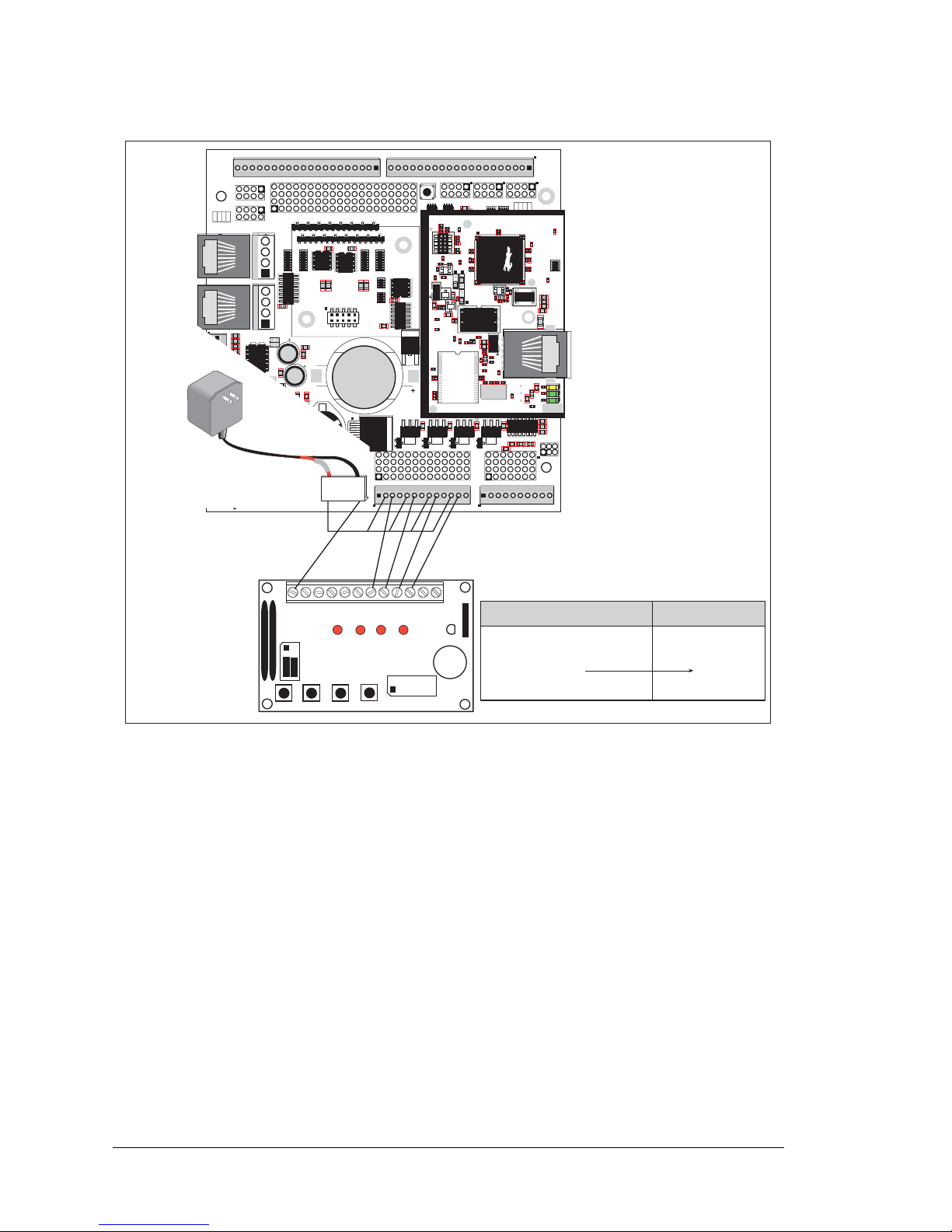
84 Wolf (BL2600)
Figure C-3. HIGH_CURRENT_IO.C Connections Between BL2600
and Demonstration Board
NOTE: +HK0…+HK3 on header J16 must be connected to +DCIN on friction-lock
connector J12 as shown in Figure C-3.
J15
J16
AIN0
AIN1
AIN2
AIN3
JP6
420 mA
AV0 AV1 AV2 AV3 AI0 AI1 AI2 AI3 AGND
GND HOUT0 +HK1 GND HOUT2 +HK3 GND
+HK0 GND HOUT1 +HK2 GND HOUT3
TXC TXF TXE 485 GND
GND RXC RXF RXE 485+
J17
GND HOUT0 +HK1 GND HOUT2 +HK3 GND
+HK0 GND HOUT1 +HK2 GND HOUT3
TXC TXF TXE 485
AIN1 AIN3 AIN5 AIN7 AGND AV1 AV3 AI1 AI3 AGND
AIN0 AIN2 AIN4 AIN6 AGND AV0 AV2 AI0 AI2 AGND
J11
20
19
R43
JP6
R44
R39
R38
R20
R33
R34
U13
R22
R21
R17
C18
C19
U12
R15
C13
R16
C10
R10
U11
J8
R14 R13 C11
AIN0 AIN1 AIN2 AIN3 AIN4 AIN5 AIN6 AIN7 AGND
C12 R12 R11
U10
BT1
C26
C27
D1
U15
C25
J12
J13
C22
R55
R42
C23
C24
R41
R40
R35
R36
R37
U14
R26
R28
R30
R19
R29
R32
R31
R56
R57
L1
R27R25
R23
R24
C20
C21
R18
C16
1
2
25
26
RXE
J14
Q19
D3
Q17D2Q18
RXC
D4
Q20
C34
RXF
485+
C35 C36 C37
JP7
485 TERM.
RESISTOR
C30
R58
R59
R60
U18
C32
C33
RCM2
U17
C31
R9
U16
R8
J10
R7
GND/EGND
RP5
RP6
U2
C4
R5
C5
R6
C6
U4
JA
RCM1
RCM3000 ETHERNET CORE MODULE
U3
RP17 RP18
34
33
16
15
1
2
1
2
15
16
33
34
C1
U1
RP3
RP4
GND
+K
DCIN
+5V
JP3,
JP4
AND
JP4
JP1 AND JP2
GND
+K
DCIN
+5V
J4 RABBITNET 1
J6 RABBITNET 0
J7
C14
C17
C15
C78
J9
C9
U9
RP16
C8
U8
R4
R3
RP15
RP14
RP12
RP13
RP11
R1
R2
C7
U6
U7
U5
RP8
RP7
RP9
RP10
C2
Q9
Q10
J5
Q12
Q15Q14 Q16
Q11
Q13
C3
Q1 Q2 Q3 Q4 Q5 Q6 Q7 Q8
JP2
JP1
J1
J2
GND DIN28 DIN24 DIN20 DIN16 GND DIO12 DIO08 DIO04 DIO00
DIN30 DIN26 DIN22 DIN18 +K DIO14 DIO10 DIO06 DIO02 GND
DIN31 DIN27 DIN23 DIN19 +K DIO15 DIO11 DIO07 DIO03 GND
GND DIN29 DIN25 DIN21 DIN17 GND DIO13 DIO09 DIO05 DIO01
GND DIO14 DIO12 DIO10 DIO08 DIO06 DIO04 DIO02 DIO00 GND
+K DIO15 DIO13 DIO11 DIO09 DIO07 DIO05 DIO03 DIO01 GND
GND DIN30 DIN28 DIN26 DIN24 GND DIN22 DIN20 DIN18 DIN16
DIN31 DIN29 DIN27 DIN25 +K DIN23 DIN21 DIN19 DIN17 GND
DIO 0007 PULLS
DIO 0815 PULLS
1
2
39
40
SW1
J3
1
2
DCIN DCIN GND GND
R111
R112
RESET
RP2
RP1
JP3
DIN 1619 PULLS
JP4
DIN 2023 PULLS
DIN 2431 PULLS
JP5
R84
C28
1
2
DS1
BL2600
Jumpers:
H1: None
H2: As shown
·
BUZZER
·
LED4
·
LED3
·
LED2
·
LED1
·
K
·
+5V
·
SW4
·
SW3
·
SW2
·
SW1
·
GND
BUZZER
H1
J1
H2
· ·
1-2
· ·
3-4
· ·
5-6
LED1 LED2 LED3 LED4
SW1 SW2 SW3 SW4
·
·
8-7
·
·
6-5
·
·
4-3
·
·
2-1
DEMO BOARD
U1
U6
R28
R38
R41
C5
C3
C9
C8
C12
C17
C23
C30
C18
C29
C35
C33
R29
R37
R39
R40
R42
Y3
C42R35
R31
R27
R25
DS1
R67
R70
J4
C79
Y4
C83
C86
GND
R75
R74
R71
DS3
DS2
R63 R64
C71
C72
C68
C64
C67
L2
U8
R49
R48
C62
R51
C61
R44
R47
C59
C49
C57
L1
R69
R72
R73
C75
C74
R58
C53
C47
C48
C45
C44
C43
JP5
C31
JP3
JP4
C28
C27
C37
C36
C32
R24
R22
C19
R23
C24
R20
C20
R19
C16
C15
R17
R18
R7
R9
R1
R8
C1
R10
R14
C4
SPD LNK ACT
J3
U5
U4
D1
Q1
C39
RP1
J12
J16
+
BL2600
(Header J16)
+DCIN (J12) ® +HK0,+HK1,+HK2,+HK3
GND (J12)
HOUT0
HOUT1
HOUT2
HOUT3
Demonstration Board
(Header J1)
GND
K
LED1
LED2
LED3
Page 89
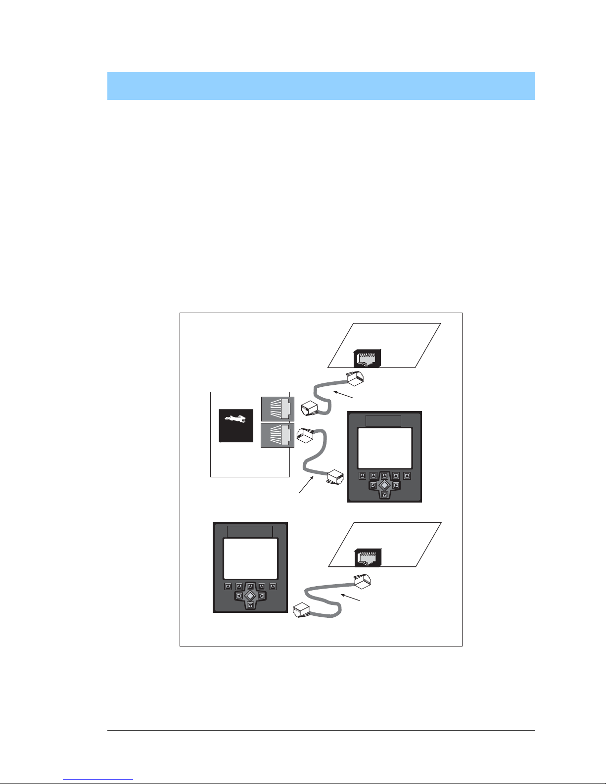
User’s Manual 85
APPENDIX D. RABBITNET
D.1 General RabbitNet Description
RabbitNet is a high-speed synchronous protocol developed by Z-World to connect peripheral cards to a master and to allow them to communicate with each other. All RabbitNet
connections are made point to point, and until a port-expansion method is available, a
RabbitNet master port can only be connected directly to a peripheral card, and the number
of peripheral cards is limited by the number of available RabbitNet ports on the master.
Figure D-1. Connecting Peripheral Cards to a Master
MASTER
SLAVE
SLAVE
MASTER
SLAVE
Rabbit 3000
®
Microprocessor
Straight-through
Ethernet cable
Crossover
Ethernet cable
Straight-through
Ethernet cable
Page 90

86 Wolf (BL2600)
Use a straight-through Ethernet cable to connect the master to slave peripheral cards, unless
you are using a device such as the OP7200 that could be used either as a master or a slave. In
this case you would use a crossover cable to connect an OP7200 that is being used as a slave.
Distances between a master unit and peripheral cards can be up to 10 m or 33 ft.
The following low-cost peripheral cards are currently available.
• Digital I/O
24 inputs, 16 push/pull outputs, 4 channels of 10-bit A/D conversion with ranges of
0 to 10 V, 0 to 1 V, and -0.25 to +0.25 V. The following connectors are used:
Signal = 0.1" friction-lock connectors
Power = 0.156" friction-lock connectors
RabbitNet = RJ-45 connector
• A/D converter
8 channels of programmable-gain 12-bit A/D conversion, configurable as current mea-
surement and differential-input pairs. 2.5 V reference voltage is available on the connector. The following connectors are used:
Signal = 0.1" friction-lock connectors
Power = 0.156" friction-lock connectors
RabbitNet = RJ-45 connector
• D/A converter
8 channels of 0–10 V 12-bit D/A conversion. The following connectors are used:
Signal = 0.1" friction-lock connectors
Power = 0.156" friction-lock connectors
RabbitNet = RJ-45 connector
• Relay card
6 relays rated at 250 V AC, 1200 V·A or 100 V DC up to 240 W. The following connectors are
used
:
Relay contacts = screw-terminal connectors
Power = 0.156" friction-lock connectors
RabbitNet = RJ-45 connector
• Display/Keypad interface
allows you to connect your own keypad with up to 64 keys and one character liquid
crystal display from 1 × 8 to 4 × 40 characters with or without backlight using standard
1 × 16 or 2 × 8 connectors. The following connectors are used:
Signal = 0.1" headers or sockets
Power = 0.156" friction-lock connectors
RabbitNet = RJ-45 connector
V isi t Z-World’s Web site for up-to-date information about additional cards and features as
they become available. The Web site also has the latest revision of this user’s manual.
Page 91

User’s Manual 87
D.2 Physical Implementation
There are four signaling functions associated with a RabbitNet connection. From the master’s point of view, the transmit function carries information and commands to the peripheral card. The receive function is used to read back information sent to the master by the
peripheral card. A clock is used to synchronize data going between the two devices at high
speed. The master is the source of this clock. A slave select (SS) function originates at the
master, and when detected by a peripheral card causes it to become selected and respond
to commands received from the master.
The signals themselves are differential RS-422, which are series-terminated at the source.
With this type of termination, the maximum frequency is limited by the round-trip delay
time of the cable. Although a peripheral card could theoretically be up to 45 m (150 ft)
from the master for a data rate of 1 MHz, Z-World recommends a practical limit of 10 m
(33 ft).
Connections between peripheral cards and masters are done using standard 8-conductor
Ethernet cables. Masters and peripheral cards are equipped with RJ-45 8-pin female connectors. The cables may be swapped end for end without affecting functionality.
D.2.1 Control and Routing
Control starts at the master when the master asserts the slave select signal (SS). Then it
simultaneously sends a serial command and clock. The first byte of a command contains
the address of the peripheral card if more than one peripheral card is connected.
A peripheral card assumes it is selected as soon as it receives the select signal. For direct
master-to-peripheral-card connections, this is as soon as the master asserts the select signal. The connection is established once the select signal reaches the addressed slave. At
this point communication between the master and the selected peripheral card is established, and data can flow in both directions simultaneously. The connection is maintained
so long as the master asserts the select signal.
Page 92

88 Wolf (BL2600)
D.3 Function Calls
The function calls described in this section are used with all RabbitNet peripheral cards,
and are available in the RNET.LIB library in the Dynamic C RABBITNET folder.
Resets, initializes, or disables a specified RabbitNet port on the master single-board computer. During
initialization, the network is enumerated and relevant tables are filled in. If the port is already initialized,
calling this function forces a re-enumeration of all devices on that port.
Call this function first before using other RabbitNet functions.
PARAMETERS
portflag is a bit that represents a RabbitNet port on the master single-board computer (from 0 to the
maximum number of ports). A set bit requires a service. If portflag = 0x03, both RabbitNet ports 0
and 1 will need to be serviced.
servicetype enables or disables each RabbitNet port as set by the port flags.
0 = disable port
1 = enable port
RETURN VALUE
0
Returns an address index to device information from a given physical node address.
This function will
check device information to determine that the peripheral card is connected to a master.
PARAMETER
pna is the physical node address, indicated as a byte.
7,6—2-bit binary representation of the port number on the master
5,4,3—Level 1 router downstream port
2,1,0—Level 2 router downstream port
RETURN VALUE
Pointer to device information. -1 indicates that the peripheral card either cannot be identified or is not
connected to the master.
SEE ALSO
rn_find
int rn_init(char portflag, char servicetype);
int rn_device(char pna);
Page 93

User’s Manual 89
Locates the first active device that matches the search criteria.
PARAMETER
srch is the search criteria structure rn_search:
unsigned int flags; // status flags see MATCH macros below
unsigned int ports; // port bitmask
char productid; // product id
char productrev; // product rev
char coderev; // code rev
long serialnum; // serial number
Use a maximum of 3 macros for the search criteria:
RN_MATCH_PORT // match port bitmask
RN_MATCH_PNA // match physical node address
RN_MATCH_HANDLE // match instance (reg 3)
RN_MATCH_PRDID // match id/version (reg 1)
RN_MATCH_PRDREV // match product revision
RN_MATCH_CODEREV // match code revision
RN_MATCH_SN // match serial number
For example:
rn_search newdev;
newdev.flags = RN_MATCH_PORT|RN_MATCH_SN;
newdev.ports = 0x03; //search ports 0 and 1
newdev.serialnum = E3446C01L;
handle = rn_find(&newdev);
RETURN VALUE
Returns the handle of the first device matching the criteria. 0 indicates no such devices were found.
SEE ALSO
rn_device
The peripheral card sends back the character the master sent. This function will check device information
to determine that the peripheral card is connected to a master.
PARAMETERS
handle is an address index to device information. Use rn_device() or rn_find() to establish the
handle.
sendecho is the character to echo back.
recdata is a pointer to the return address of the character from the device.
RETURN VALUE
The status byte from the previous command. -1 means that device information indicates the peripheral
card is not connected to the master.
int rn_find(rn_search *srch);
int rn_echo(int handle, char sendecho,
char *recdata);
Page 94

90 Wolf (BL2600)
Writes a string to the specified device and register. Waits for results. This function will check device infor-
mation to determine that the peripheral card is connected to a master.
PARAMETERS
handle is an address index to device information. Use rn_device() or rn_find() to establish the
handle.
regno is the command register number as designated by each device.
data is a pointer to the address of the string to write to the device.
datalen is the number of bytes to write (0–15).
NOTE: A data length of 0 will transmit the one-byte command register number.
RETURN VALUE
The status byte from the previous command. -1 means that device information indicates the peripheral
card is not connected to the master, and -2 means that the data length was greater than 15.
SEE ALSO
rn_read
Reads a string from the specified device and register. Waits for results. This function will check device
information to determine that the peripheral card is connected to a master.
PARAMETERS
handle is an address index to device information. Use rn_device() or rn_find() to establish the
handle.
regno is the command register number as designated by each device.
recdata is a pointer to the address of the string to read from the device.
datalen is the number of bytes to read (0–15).
NOTE: A data length of 0 will transmit the one-byte command register number.
RETURN VALUE
The status byte from the previous command. -1 means that device information indicates the peripheral
card is not connected to the master, and -2 means that the data length was greater than 15.
SEE ALSO
rn_write
int rn_write(int handle, int regno, char *data,
int datalen);
int rn_read(int handle, int regno, char *recdata,
int datalen);
Page 95

User’s Manual 91
Sends a reset sequence to the specified peripheral card. The reset takes approximately 25 ms before the
peripheral card will once again execute the application. Allow 1.5 seconds after the reset has completed
before accessing the peripheral card. This function will check peripheral card information to determine
that the peripheral card is connected to a master.
PARAMETERS
handle is an address index to device information. Use rn_device() or rn_find() to establish the
handle.
resettype describes the type of reset.
0 = hard reset—equivalent to power-up. All logic is reset.
1 = soft reset—only the microprocessor logic is reset.
RETURN VALUE
The status byte from the previous command. -1 means that device information indicates the peripheral
card is not connected to the master.
Sets software watchdog timeout period. Call this function prior to enabling the software watchdog timer.
This function will check device information to determine that the peripheral card is connected to a master.
PARAMETERS
handle is an address index to device information. Use rn_device() or rn_find() to establish the
handle.
timeout is a timeout period from 0.025 to 6.375 seconds in increments of 0.025 seconds. Entering a
zero value will disable the software watchdog timer.
RETURN VALUE
The status byte from the previous command. -1 means that device information indicates the peripheral
card is not connected to the master.
int rn_reset(int handle, int resettype);
int rn_sw_wdt(int handle, float timeout);
Page 96

92 Wolf (BL2600)
Enables the hardware and/or software watchdog timers on a peripheral card. The software on the peripheral card will keep the hardware watchdog timer updated, but will hard reset if the time expires. The
hardware watchdog cannot be disabled excep t by a hard reset on the peripheral card. The software watchdog timer must be updated by software on the master. The peripheral card will soft reset if the timeout set
by rn_sw_wdt() expires.
This function will check device information to determine that the peripheral
card is connected to a master.
PARAMETERS
handle is an address index to device information. Use rn_device() or rn_find() to establish the
handle.
wdttype
0 enables both hardware and software watchdog timers
1 enables hardware watchdog timer
2 enables software watchdog timer
RETURN VALUE
The status byte from the previous command. -1 means that device information indicates the peripheral
card is not connected to the master.
SEE ALSO
rn_hitwd, rn_sw_wdt
Hits software watchdog. Set the timeout period and enable the software watchdog prior to using this
function.
This function will check device info rmati on t o determ in e that the peripheral card is connected to
a master.
PARAMETERS
handle is an address index to device information. Use rn_device() or rn_find() to establish the
handle.
count is a pointer to return the present count of the software watchdog timer. The equivalent time left in
seconds can be determined from count × 0.025 seconds.
RETURN VALUE
The status byte from the previous command. -1 means that device information indicates the peripheral
card is not connected to the master.
SEE ALSO
rn_enable_wdt, rn_sw_wdt
int rn_enable_wdt(int handle, int wdttype);
int rn_hitwd(int handle, char *count);
Page 97

User’s Manual 93
Reads the status of which reset occurred and whether any watchdogs are enabled.
PARAMETERS
handle is an address index to device information. Use rn_device() or rn_find() to establish the
handle.
retdata is a pointer to the return address of the communication byte. A set bit indicates which error
occurred. This register is cleared when read.
7—HW reset has occurred
6—SW reset has occurred
5—HW watchdog enabled
4—SW watchdog enabled
3,2,1,0—Reserved
RETURN VALUE
The status byte from the previous command.
PARAMETERS
handle is an address index to device information. Use rn_device() or rn_find() to establish the
handle.
retdata is a pointer to the return address of the communication byte. A set bit indicates which error
occurred. This register is cleared when read.
7—Data available and waiting to be processed MOSI (master out, slave in)
6—Write collision MISO (master in, slave out)
5—Overrun MOSI (master out, slave in)
4—Mode fault, device detected hardware fault
3—Data compare error detected by device
2,1,0—Reserved
RETURN VALUE
The status byte from the previous command.
int rn_rst_status(int handle, char *retdata);
int rn_comm_status(int handle, char *retdata);
Page 98
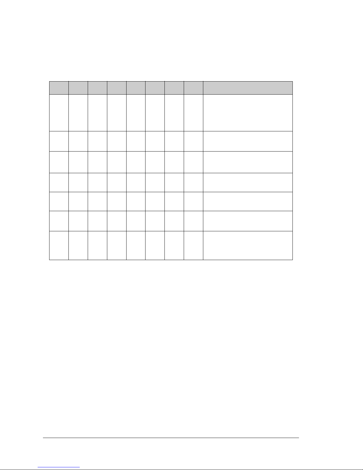
94 Wolf (BL2600)
D.3.1 Status Byte
Unless otherwise specified, funct ions returning a status byte will have the following format
for each designated bit.
7 6 5 4 3 2 1 0
××
00 = Reserved
01 = Ready
10 = Busy
11 = Device not connected
×
0 = Device
1 = Router
×
0 = No error
1 = Communication error
*
* Use the function rn_comm_status() to determine which error occurred.
×
Reserved for individual peripheral
cards
×
Reserved for individual peripheral
cards
×
0 = Last command accepted
1 = Last command unexecuted
×
0 = Not expir ed
1 = HW or SW watchdog timer
expired
†
† Use the function rn_rst_status() to determine which timer expired.
Page 99

User’s Manual 95
NOTICE TO USERS
Z-WORLD PRODUCTS ARE NOT AUTHORIZED FOR USE AS CRITICAL COMPONENTS IN LIFESUPPORT DEVICES OR SYSTEMS UNLESS A SPECIFIC WRITTEN AGREEMENT REGARDING
SUCH INTENDED USE IS ENTERED INTO BETWEEN THE CUSTOMER AND Z-WORLD PRIOR
TO USE. Life-support devices or systems are devices or systems intended for surgical implantation into the
body or to sustain life, and whose failure to perfo rm, when properly used in accor dance with instructions for
use provided in the labeling and user’s manual, can be reasonably expected to result in significant injury.
No complex software or hardware system is perfect. Bugs are always present in a system of any size. In
order to prevent danger to life or property, it is the responsibility of the system designer to incorporate
redundant protective mechanisms appropriate to the risk involved.
All Z-World products are 100 percent functionally tested. Additional testing may include visual quality control inspections or mechanical defects analyzer inspections. Specifications are based on characterization of
tested sample units rather than testing over temperature and voltage of each unit. Z-World products may
qualify components to operate within a range of parameters that is different from the manufacturer’s recommended range. This strategy is believed to be more economical and effective. Additional testing or burn-in
of an individual unit is available by special arrangement.
Page 100

96 Wolf (BL2600)
 Loading...