

Page 1
FCC/IC
ZW32 Smart Outlet Manual
Federal Communications Commission (FCC) Statement
FCC Caution: Any changes or modifications not expressly approved by the party responsible for
compliance could void the user ’s authority to operate this equipment.
This device complies with Part 15 of the FCC Rules. Operation is subject to the following two
conditions: (1) This device may not cause harmful interference, and (2) this device must accept any
interference received, including interference that may cause undesired operation.
NOTE: This equipment has been tested and found to comply with the limits for a Class B digital device,
pursuant to Part 15 of the FCC Rules. These limits are designed to provide reasonable protection
against harmful interference in a residential installation. This equipment generates, uses and can
radiate radio frequency energy and, if not installed and used in accordance with the instructions,
may caus harmful interference to radio communications.However, there is no guarantee that
interference will not occur in a particular installation. If this equipment does cause harmful interference
to radio or television reception, which can be determined by turning the equipment off and on,
the user is encouraged to try to correct the interference by one or more of the following measures:
Reorient or relocate the receiving antenna.Increase the separation between the equipment and
receiver.Connect the equipment into an outlet on a circuit different from that to which the receiver
is connected.Consult the dealer or an experienced radio/TV technician for help.This equipment
should be installed and operated with minimum distance 20cm between the radiator and your body.
IC Caution:
This device complies with Industry Canada licence-exempt RSS standard(s). Operation is subject
to the following two conditions: (1) this device may not cause interference, and (2) this device must
accept any interference, including interference that may cause undesired
operation of the device.
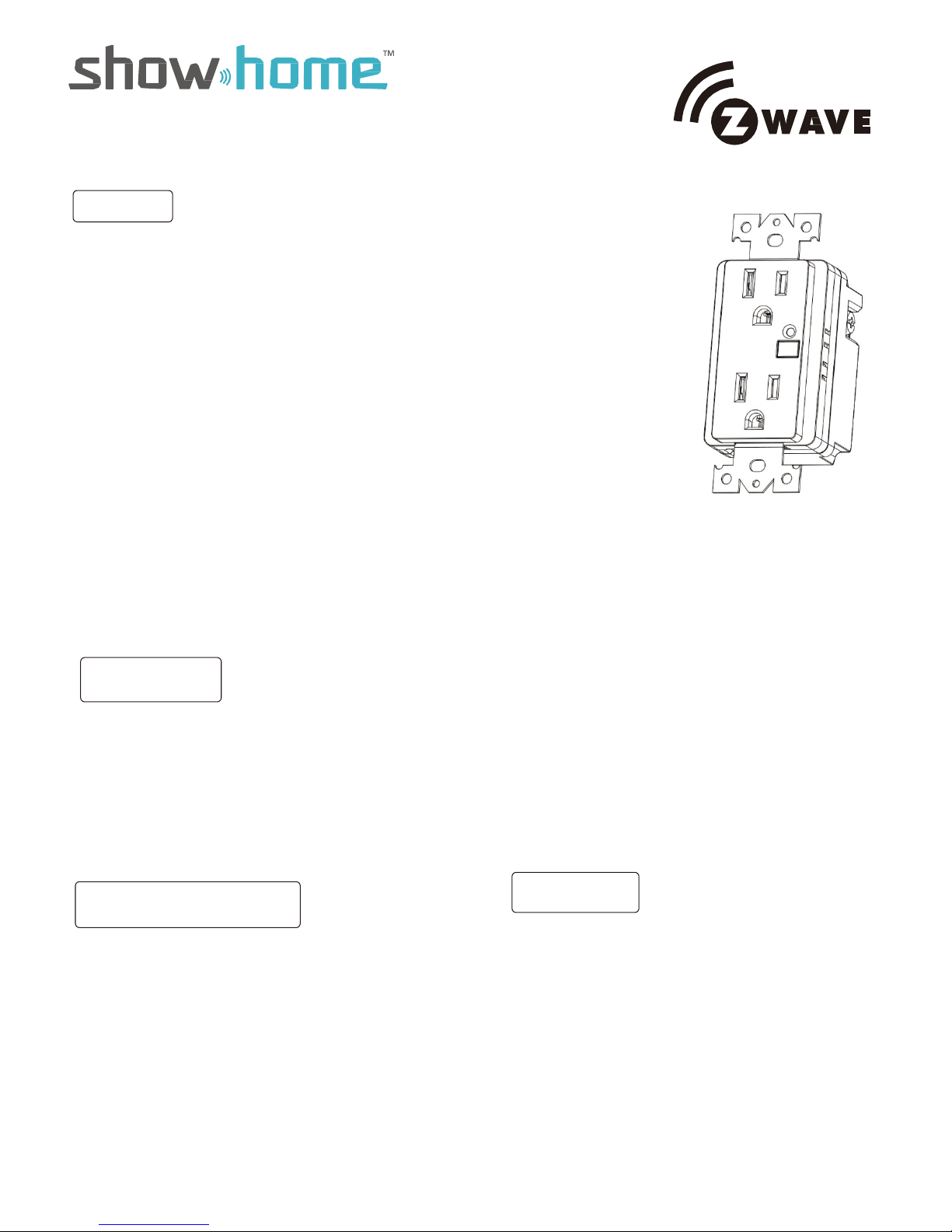
In-wall smart outlet
DECLARATION DE CONFORMITE D'INDUSTRIE CANADA
Le présent appareil est conforme aux CNR d’Industrie Canada applicables aux appareils radio
exempts de licence. L’exploitation est autorisée aux deux conditions suivantes :
(1) l’appareil ne doit pas produire de brouillage;
(2) l’utilisateur de l’appareil doit accepter tout brouillage radioélectrique subi, même.
si le bro u il la g e es t s us c ep ti bl e d’en compromettre le fonctionnement.
WARRANTY
Show Home Products warrants this product to be free from manufacturing defects for
a period of two years from the original date of consumer purchase. This warranty is limited
to the repair or replacement of this product only and does not extend to consequential or
incidental damage to other products that may be used with this product.
This warranty is in lieu of all other warranties, expressed or implied. Some states do not
allow limitations on how long an implied warranty lasts or permit the exclusion or limitation
of incidental or consequential damage, so the above limitations may not apply to you.
This warranty gives you specific rights, and you may also have other rights which vary from
state to state. if the unit should prove defective within the warranty period.
SPECIFICATIONS
Model:ZW32
Power: 120 VAC, 60 Hz.
Signal (Frequency): 908.42 MHz.
Maximum Loads: 600W, incandescent,
½ HP Motor or 1800W (15A) Resistive
Range: Up to 100 feet line of sight between the
Wireless Controller and the closest Z-Wave
receiver module.
Operating Temperature Range: 32-104° F (0-40° C)
For indoor use only.
Specifications subject to change without notice
due to continuing product improvement
Website www.ishowlights.com
WARNING
RISK OF FIRE
RISK OF ELECTRICAL SHOCK
RISK OF BURNS
CONTROLLING APPLIANCES:
EXERCISE EXTREME CAUTION WHEN USING Z-WAVE
DEVICES TO CONTROL APPLIANCES. OPERATION
OF THE Z-WAVE DEVICE MAY BE IN A DIFFERENT
ROOM THAN THE CONTROLLED APPLIANCE, ALSO AN
UNINTENTIONAL ACTIVATION MAY OCCUR IF THE WRONG
BUTTON ON THE REMOTE IS PRESSED. Z-WAVE DEVICES
MAY AUTOMATICALLY BE POWERED ON DUE TO TIMED
EVENT PROGRAMMING. DEPENDING UPON THE APPLIANCE, THESE UNATTENDED OR UNINTENTIONAL OPERATIONS COULD POSSIBLY RESULT IN A HAZARDOUS
CONDITION. FOR THESE REASONS, WE RECOMMEND
DO NOT RETURN THIS PRODUCT TO THE STORE
THE FOLLOWING:
DO NOT USE Z-WAVE DEVICES TO CONTROL ELECTRIC
HEATERS OR ANY OTHER APPLIANCES WHICH MAY PRESENT A HAZARDOUS CONDITION DUE TO UNATTENDED OR
UNINTENTIONAL OR AUTOMATIC POWER ON CONTROL.
Page 2
Getting To Know Your New Z-Wave Device
• One Z-wave remote controlled outlet
• Remote ON/OFF control via the Z-Wave controller/network
• Manual ON/OFF control with the manual/program button
• One Always-ON pass through outlet
• Blue LED indicates outlet location in a dark room
2
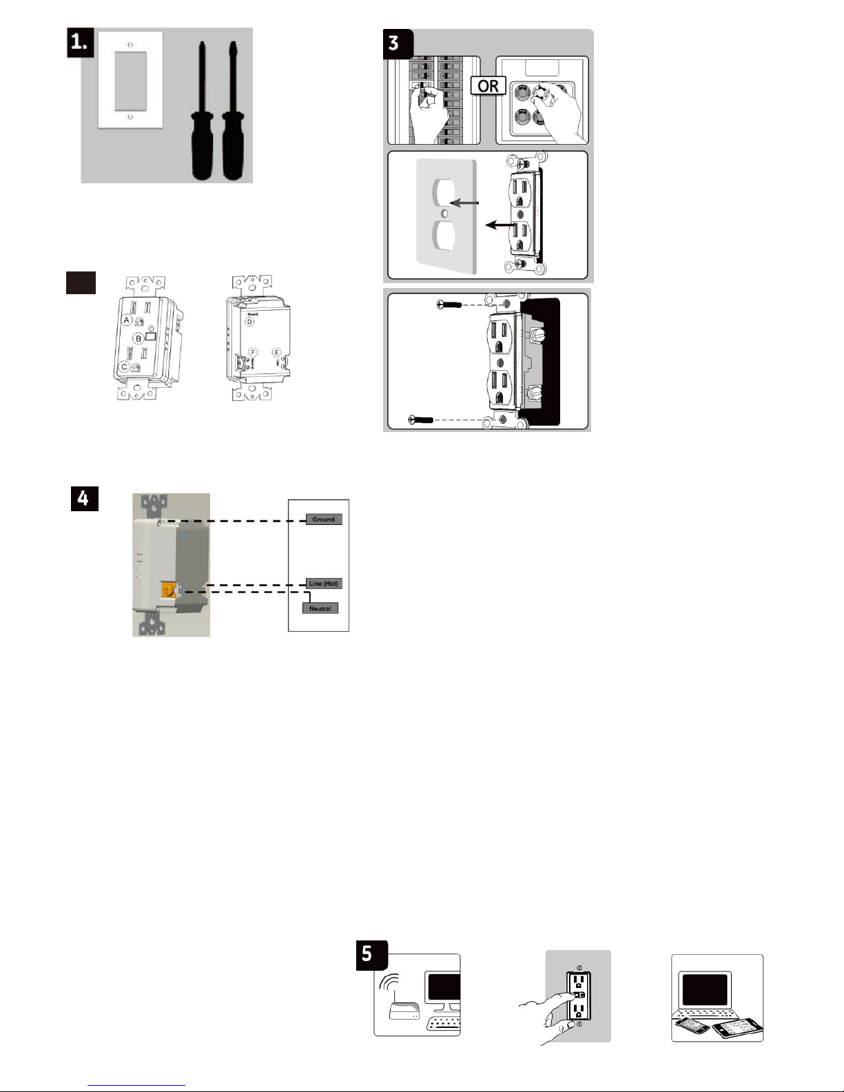
Step:
1. Shut off power to the circuit at
circuit breaker or fuse box.
2. Remove wall plate.
3. Remove the outlet
mounting screws.
4. Carefully remove the outlet
from the outlet box.
5. Disconnect the wires from the
existing outlet. Be careful to
label wires according to the
previous terminal connection.
6. There are three terminal on the
Z-Wave smart outlet.
A. GROUND — Green
B. Neutral — White
C. Line (Hot) — Black
(connected to power) Match
these to the wires connected
on the existing outlet.
Warning
:
Verify power is OFF
to switch box before continuing
A. Always-on outlet
B. Manual/Program Button
C. Z-Wave
controlled outlet
Step:
D.Ground(green)
E.Line(Hot)
F.Neutral(White)
Observe Important Wiring Information
Always follow the recommended wire strip lengths and wiring
combination when making wiring connections. You may wish to
consult a electrician with questions or for professional installation.
Important: The wire connectors included with this receptacle
are intended to only be used with copper wire. Consult a qualified
electrician if you have aluminum wiring.
Wire Gauge Requirements
Use 14 AWG or larger wires suitable for at least 80° C for
supplying HOT, neutral, ground and connections.
1. Remove stripped insulation from wires of Z-Wave outlet.
2. Hold stripped ends together in parallel and align any frayed strands.
3.
Push wires firmly into a wire nut. Twist the wire nut clockwise with fingers until tight. Pull wires to check for tightness.
4.
Use the included wire nuts to make the following connections:A. Connect the green wire from the controlled outlet to the
green or bare ground wire removed from the old outlet.B. Connect the white wire from the controlled outlet to the
neutral (white) wire removed from the old outlet.C. Connect the black wire from the controlled outlet to the Line/hot (black)
wire removed from the old outlet.
5.
Insert Z-Wave controlled outlet into the box being careful not to pinch or crush wires.
6.
Secure the controlled outlet to the box using the supplied screws.
7.
Mount the wall plate.
8.
Reapply power to the circuit at fuse box or circuit breaker and test the system.
Linking your device
1. Follow the instructions for your Z-wave certified
controller to include a device to the Z-wave network.
2. Once the controller is ready to include your device,
press and release the Program Button to include it in the network.
Note: Your controller may need to be within 10 feet of the device to be included.
3. Once your controller has confirmed that the device has been included, refresh the Z-wave network to optimize performance.
Please reference the controller/gateway’s
manual for instructions.Now you have
complete control to turn your fi xture ON/OFF
according to groups, scenes, schedules and
interactive automations programmed by
your controller.If your Z-wave certified
controller features Remote Access, you can
now control your fixture from your mobile devices.
Note: To exclude and reset the device, follow the
instructions provided by your Z-Wave controller.
 Loading...