


Instruction
Z-Ware SDK 7.13.0 Web User's Guide
Document No.:
INS14428
Version:
10
Description:
Z-Ware is a Z-Wave Plus v2 SmartStart Web Gateway over ZIPGW. It comes with
sample Z-Ware Apps as native iOS/Android apps and web pages for Tablet &
Phone
Written By:
SAMBAT
Date:
2019-12-06
Reviewed By:
NTJ;HAKRONER;TRBOYD;SCBROWNI;JCC
Restrictions:
Public
Approved by:
Date CET Initials Name Justification
2019-12-06 01:55:46 NTJ Niels Johansen
This document is the property of Silicon Labs. The data contained herein, in whole or in
part, may not be duplicated, used or disclosed outside the recipient for any purpose. This
restriction does not limit the recipient's right to use information contained in the data if
it is obtained from another source without restriction.

INS14428-10 Z-Ware SDK 7.13.0 Web User Guide 2019-12-06
silabs.com | Building a more connected world.
Page ii of viii
REVISION RECORD
Doc. Ver.
DateByPages
affected
Brief description of changes
1
20180726
SNA
ALL
SDK v7.00.00: Cloned from SDK v1.11
2
20181011
SNA
4,8,
21,23,60
Clarified role, n/w ops & CC support; Clarified portal registration
Tab UI Dimmer, Door Lock; Eng UI Configuration CC
3
20181024
SNA
4, 33
Updated ZIP CC support; Added Tab UI Maintenance (Device) Network Health
4
20181122
SNA4v7.00.02 beta: removed older ZIPGW info, Corrected mailbox CC support version
5
20181122
SNA1Removed BBB reference
6
20190215
20190220
SNA
1,3,
6,
22,26,23,
55,61,38,
3,70,
22,30,42,50,
50
SDK v7.11.0: RPi3B+, Control CC: Window Covering; N/W IMA v2, User Code v2;
updated apps URLs;
Tab UI: added Windows Covering, Firmware Backup, User Code v2
Eng UI: added Windows Covering, Firmware Backup; updated About Page
Removed Lib info, Added reference to Lib
Tab/Eng UI: Binary Switch duration; Grant Key reject
Eng UI: multilevel switch duration
7
20190318
SNA
3, 4,32,34
Corrected controlled & supported CC table, reference in Update Node/Network
8
20190531
SNA
3, 4, 5, 8,
36, 26, 18,
61, 48, 54
v7.11.1:CC control, CC support, Scenes Sound switch action, ZIPGW Portal Config,
Tab UI: About, Firmware Update, Device page ZIP GW & Portal settings
Eng UI: Firmware Update, Binary Sensor, User Code
9
20190913
SNA
3, 5,
26,
39, 50, 58, 61
V7.11.2: CC Control, Scenes Action Window Covering
Tab UI: Battery, Indicator, Firmware
Eng UI: Feature, Battery, Indicator, Firmware
10
20191115
20191205
SNA
3, 4,
6, 41, 62, 55,
34,26
v7.13.0: CC Control - Protection, DoorLock Logging; CC Support - ZIP v5
removed Tab/Phone UI restrictions, Eng UI – Identify, Protection & Doorlock Logging
Tab/Phone UI – Identify, Protection & Doorlock Logging
Removed Eng UI: Command Queueing
Added techpub edits, Moved Multi CMD CC support to ZIPGW, NW MGMT PROXY v3

INS14428-10 Z-Ware SDK 7.13.0 Web User Guide 2019-12-06
silabs.com | Building a more connected world.
Page iii of viii
Table of Contents
1 INTRODUCTION ............................................................................................................................1
1.1 Purpose..............................................................................................................................................1
1.2 Audience and Requirements .............................................................................................................2
2 OVERVIEW ....................................................................................................................................3
2.1 Z-Ware Library...................................................................................................................................3
2.2 CC Control..........................................................................................................................................3
2.3 CC Support.........................................................................................................................................4
2.4 Scenes................................................................................................................................................5
2.5 Bundled Z-Ware Apps........................................................................................................................6
3 ACCESS .........................................................................................................................................7
3.1 Login ..................................................................................................................................................7
3.2 CE.......................................................................................................................................................7
3.3 Portal .................................................................................................................................................7
3.3.1 Registration .............................................................................................................................8
3.3.2 ZIPGW Configuration...............................................................................................................8
3.3.2.1 Obtaining Ethernet MAC address of ZIPGW.......................................................................8
3.3.2.2 Downloading certificates....................................................................................................9
3.3.2.3 Configuring for Portal .......................................................................................................10
3.3.3 Reset Password .....................................................................................................................10
4 TABLET/PC AND PHONE UI..........................................................................................................11
4.1 Scenes..............................................................................................................................................11
4.1.1 Scene Summary.....................................................................................................................13
4.1.2 Scene Action..........................................................................................................................14
4.1.3 Scene Schedule......................................................................................................................15
4.1.4 Scene Trigger.........................................................................................................................15
4.1.5 Security Scene Summary.......................................................................................................16
4.1.6 Security Scene Arming...........................................................................................................16
4.1.7 Security Scene Disarming ......................................................................................................17
4.1.8 Security Scene Alarm.............................................................................................................17
4.1.9 Security Scene Alarm Popup .................................................................................................18
4.2 Devices ............................................................................................................................................18
4.2.1 Binary Sensor Device.............................................................................................................21
4.2.2 Alarm/Notification Device.....................................................................................................21
4.2.3 Meter Device.........................................................................................................................21
4.2.4 Multilevel Sensor Device.......................................................................................................21
4.2.5 Binary Switch Device .............................................................................................................22
4.2.6 Dimmer Device......................................................................................................................22
4.2.7 Shades Device .......................................................................................................................22
4.2.8 Door Lock Device...................................................................................................................23
4.2.9 Central Scene Controller .......................................................................................................24

INS14428-10 Z-Ware SDK 7.13.0 Web User Guide 2019-12-06
silabs.com | Building a more connected world.
Page iv of viii
4.2.10 Thermostat Device................................................................................................................25
4.2.11 Barrier Operator Device ........................................................................................................25
4.2.12 Sound Switch Device.............................................................................................................25
4.2.13 Other Interfaces ....................................................................................................................26
4.3 More................................................................................................................................................29
4.3.1 Maintenance (Network) ........................................................................................................30
4.3.1.1 Add/Remove Devices (Optionally On Behalf)...................................................................30
4.3.1.2 Reset Network..................................................................................................................32
4.3.1.3 Update Network...............................................................................................................32
4.3.1.4 Set Learn Mode ................................................................................................................32
4.3.1.5 Broadcast NIF ...................................................................................................................33
4.3.1.6 Network Health ................................................................................................................33
4.3.2 Maintenance (Device) ...........................................................................................................33
4.3.2.1 Remove/Replace Failed Devices (Optionally On Behalf) ..................................................34
4.3.2.2 Update Device ..................................................................................................................34
4.3.2.3 Send NIF............................................................................................................................34
4.3.2.4 Identify .............................................................................................................................34
4.3.3 SmartStart .............................................................................................................................35
4.3.3.1 Add/Edit Device................................................................................................................36
4.3.3.2 Z-Wave Reset Requirement Detection.............................................................................36
4.3.4 About.....................................................................................................................................36
4.4 Native UI..........................................................................................................................................37
5 ENGINEERING UI .........................................................................................................................38
5.1 Home ...............................................................................................................................................38
5.2 About...............................................................................................................................................38
5.3 Features...........................................................................................................................................39
5.4 Network Manager ...........................................................................................................................41
5.4.1 Security 2 Operations............................................................................................................42
5.4.2 Network Health Check ..........................................................................................................43
5.5 SmartStart .......................................................................................................................................43
5.6 Controller ........................................................................................................................................46
5.7 Interfaces.........................................................................................................................................47
5.7.1 Basic ......................................................................................................................................47
5.7.2 Binary Sensor.........................................................................................................................48
5.7.3 Multi-Level Sensor.................................................................................................................48
5.7.4 Alarm/Notification ................................................................................................................49
5.7.5 Meter ....................................................................................................................................49
5.7.6 Battery...................................................................................................................................50
5.7.7 Binary Switch.........................................................................................................................50
5.7.8 Multi-Level Switch.................................................................................................................50
5.7.9 Color Switch Interface ...........................................................................................................51
5.7.10 Central Scene Controller .......................................................................................................52
5.7.11 Door Lock ..............................................................................................................................53
5.7.12 User Code ..............................................................................................................................54
5.7.13 Door Lock Logging Interface..................................................................................................55

INS14428-10 Z-Ware SDK 7.13.0 Web User Guide 2019-12-06
silabs.com | Building a more connected world.
Page v of viii
5.7.14 Barrier Operator Interface ....................................................................................................55
5.7.15 Window Covering Interface...................................................................................................55
5.7.16 Thermostat-Related Interfaces .............................................................................................56
5.7.16.1 Thermostat Fan ................................................................................................................56
5.7.16.2 Thermostat Mode and Operating State ...........................................................................56
5.7.16.3 Thermostat SetPoint.........................................................................................................57
5.7.17 Sound Switch.........................................................................................................................58
5.7.18 Indicator................................................................................................................................58
5.7.19 Naming/Location...................................................................................................................59
5.7.20 Association............................................................................................................................59
5.7.21 Configuration ........................................................................................................................60
5.7.22 Wakeup .................................................................................................................................60
5.7.23 Firmware Update ..................................................................................................................61
5.7.24 Protection..............................................................................................................................62
5.7.25 Z/IP Gateway.........................................................................................................................62
5.8 Scenes..............................................................................................................................................65
5.9 Security Scenes................................................................................................................................67
REFERENCES.......................................................................................................................................70
Table of Tables
Table 1: UI-Controlled Z-Wave CCs..............................................................................................................3
Table 2: Controlled Z-Wave CCs Inherited through Library.........................................................................3
Table 3: Supported Z-Wave CCs Pushed down from Z-Ware ......................................................................4
Table 4: ZIPGW SDK 7.13 Supported Z-Wave CCs........................................................................................4
Table 5: Scenes Actions Supported .............................................................................................................5
Table 6: Scenes Event Triggers Supported...................................................................................................5
Table 7: Bundled Z-Ware Apps and URIs .....................................................................................................6
Table 8: Z-Wave Network Buttons Mapping .............................................................................................42
Table of Figures
Figure 1: Z-Ware CE Running within a Home on RPi3B+ .............................................................................1
Figure 2: Z-Ware Portal in the Cloud Connected to Multiple Homes ..........................................................1
Figure 3: Login Page.....................................................................................................................................7
Figure 4: Portal Registration Page ...............................................................................................................8
Figure 5: ZIPGW MAC Address.....................................................................................................................9
Figure 6: Portal Reset Password Page .......................................................................................................10
Figure 7: Tab UI - Scenes............................................................................................................................11
Figure 8: Tab UI - Scenes Edit ....................................................................................................................12
Figure 9: Tab UI - Scenes Toggle ................................................................................................................13
Figure 10: Tab UI: Scene View Summary ...................................................................................................14

INS14428-10 Z-Ware SDK 7.13.0 Web User Guide 2019-12-06
silabs.com | Building a more connected world.
Page vi of viii
Figure 11: Tab UI - Scene View Action.......................................................................................................15
Figure 12: Tab UI - Scene Schedule............................................................................................................15
Figure 13: Tab UI - Scene Trigger...............................................................................................................16
Figure 14: Tab UI - Security Scene Summary .............................................................................................16
Figure 15: Tab UI - Security Scene Arm .....................................................................................................17
Figure 16: Tab UI - Security Scene Disarm .................................................................................................17
Figure 17: Tab UI - Security Scene Alarm...................................................................................................18
Figure 18: Tab UI - Security Scene Alarm Popup .......................................................................................18
Figure 19: Tab UI - Devices ........................................................................................................................19
Figure 20: Tab UI - Show Details................................................................................................................20
Figure 21: Tab UI - Binary Sensor...............................................................................................................21
Figure 22: Tab UI – Alarm/Notification Interface Type/Event ...................................................................21
Figure 23: Tab UI - Meter Interface ...........................................................................................................21
Figure 24: Tab UI - Multilevel Sensor Interface .........................................................................................21
Figure 25: Tab UI - Binary Switch Device ...................................................................................................22
Figure 26: Tab UI - Dimmer (Multilevel Switch Non-Motor) Device..........................................................22
Figure 27: Tab UI - Shades (Multilevel Switch Motor) Device ...................................................................22
Figure 28: Tab UI - Shades (Window Covering) Device..............................................................................23
Figure 29: Tab UI - Door Lock Device Simple View ....................................................................................23
Figure 30: Tab UI - Door Lock Device Advanced View ...............................................................................24
Figure 31: Tab UI - Central Scene Controller Device..................................................................................24
Figure 32: Tab UI - Thermostat Device ......................................................................................................25
Figure 33: Tab UI - Barrier Operator Device ..............................................................................................25
Figure 34: Tab UI - Sound Switch Device ...................................................................................................25
Figure 35: Tab UI – Group Interface (Association or Multichannel Association with Advanced Group
Information) .......................................................................................................................................26
Figure 36: Tab UI - Wakeup Interface........................................................................................................26
Figure 37: Tab UI - Door Lock Logging Interface........................................................................................26
Figure 38: Tab UI - Battery Interface .........................................................................................................27
Figure 39: Tab UI - Indicator Interface.......................................................................................................27
Figure 40: Tab UI - Configuration Interface ...............................................................................................28
Figure 41: Tab UI - Protection Interface ....................................................................................................28
Figure 42: Tab UI - Firmware Update Interface .........................................................................................29
Figure 43: Tab UI – More: Settings ............................................................................................................30
Figure 44: Tab UI – Maintenance (Network) .............................................................................................30
Figure 45: Tab UI - Add New Device: Initiate.............................................................................................31
Figure 46: Tab UI - Add New Device: Grant Keys.......................................................................................31
Figure 47: Tab UI - Add New Device: DSK..................................................................................................32
Figure 48: Tab UI - Add New Device: CSA DSK info....................................................................................32
Figure 49: Tab UI – Set Learn Mode ..........................................................................................................33
Figure 50: Tab UI - Network Health ...........................................................................................................33
Figure 51: Tab UI – Maintenance (Device) ................................................................................................34
Figure 52: Tab UI – SmartStart List ............................................................................................................35
Figure 53: Tab UI - SmartStart Add Device ................................................................................................36
Figure 54: Tab UI - SmartStart Z-Wave Reset Requirement Detection......................................................36

INS14428-10 Z-Ware SDK 7.13.0 Web User Guide 2019-12-06
silabs.com | Building a more connected world.
Page vii of viii
Figure 55: Tab UI - About...........................................................................................................................37
Figure 56: Native Phone UI - Main Page....................................................................................................37
Figure 57: Native Phone UI – Accounts Page.............................................................................................37
Figure 58: Eng UI - Home Page ..................................................................................................................38
Figure 59: Eng UI - About Page ..................................................................................................................38
Figure 60: Eng UI – Features......................................................................................................................39
Figure 61: Eng UI - Scene Features ............................................................................................................40
Figure 62: Eng UI - Security Scene Features ..............................................................................................40
Figure 63: Eng UI - Network Manager Page...............................................................................................41
Figure 64: Eng UI - Network Operation Progress.......................................................................................41
Figure 65: Eng UI - S2 Accepting Security Keys..........................................................................................42
Figure 66: Eng UI - S2 Entering DSK ...........................................................................................................42
Figure 67: Eng UI - S2 CSA..........................................................................................................................43
Figure 68: Eng U - S2 Set Learn Mode .......................................................................................................43
Figure 69: Eng UI – Network Health Check................................................................................................43
Figure 70: Eng UI - SmartStart List.............................................................................................................44
Figure 71: Eng UI - SmartStart Add/Edit Device ........................................................................................45
Figure 72: Eng UI – SmartStart Z-Wave Reset Required Detection ...........................................................46
Figure 73: Eng UI - Node Controller Page ..................................................................................................47
Figure 74: Eng UI - Basic Interface .............................................................................................................47
Figure 75: Eng UI - Binary Sensor Interface ...............................................................................................48
Figure 76: Eng UI - Multilevel Sensor Interface .........................................................................................48
Figure 77: Eng UI – Alarm/Notification Interface ......................................................................................49
Figure 78: Eng UI - Meter Interface ...........................................................................................................49
Figure 79: Eng UI - Battery Interface .........................................................................................................50
Figure 80: Eng UI - Binary Switch Interface ...............................................................................................50
Figure 81: Eng UI - Multilevel Switch Interface..........................................................................................51
Figure 82: Eng UI - Color Switch Interface .................................................................................................51
Figure 83: Eng UI - Central Scene Controller Interface ..............................................................................52
Figure 84: Eng UI - Door Lock Interface .....................................................................................................53
Figure 85: Eng UI - User Code Interface.....................................................................................................54
Figure 86: Eng UI - Door Lock Logging Interface........................................................................................55
Figure 87: Eng UI - Barrier Operator Interface ..........................................................................................55
Figure 88: Eng UI - Window Covering Interface.........................................................................................55
Figure 89: Eng UI - Thermostat Fan Interface............................................................................................56
Figure 90: Eng UI - Thermostat Mode and State Interface........................................................................56
Figure 91: Eng UI - Thermostat Setpoint Interface ....................................................................................57
Figure 92: Eng UI - Sound Switch Interface................................................................................................58
Figure 93: Eng UI - Indicator Interface.......................................................................................................58
Figure 94: Eng UI - Name/Location Interface ............................................................................................59
Figure 95: Eng UI – Group Interface ..........................................................................................................59
Figure 96: Eng UI - Configuration Interface ...............................................................................................60
Figure 97: Eng UI - Wakeup Interface........................................................................................................61
Figure 98: Eng UI - Firmware Update Interface .........................................................................................61
Figure 99: Eng UI - Protection Interface ....................................................................................................62

INS14428-10 Z-Ware SDK 7.13.0 Web User Guide 2019-12-06
silabs.com | Building a more connected world.
Page viii of viii
Figure 100: Eng UI – ZIPGW Interface Portal Mode...................................................................................63
Figure 101: Eng UI - ZIPGW Interface Standalone Mode...........................................................................64
Figure 102: Eng UI - Scenes Page...............................................................................................................65
Figure 103: Eng UI - Scene Edit..................................................................................................................66
Figure 104: Eng UI - Security Scenes Page .................................................................................................67
Figure 105: Eng UI - Security Scene Edit ....................................................................................................68
Figure 106: Eng UI - Security Scene Notification Edit ................................................................................69
INS14428-10 Z-Ware SDK 7.13.0 Web User Guide 2019-12-06
silabs.com | Building a more connected world.
Page 1 of 73
1 INTRODUCTION
Z-Wave
Device
iPad/iPhone
Android Phone/Tab
RPi3B+
Z-Ware Web Server
Z-Ware Library
ZIPGW
Z-Ware Native Apps
Z-Wave
Device
PC Web Browser
Z-Ware Web Apps
RPi3B+
Z-Wave
Device
iPad/iPhone
Android Phone/Tab
Cloud Linux VM
Z-Ware Web Server
Z-Ware Library
ZIPGW
Z-Ware Native Apps
Z-Wave
PC Web Browser
Internet
Z-Ware Apps
1.1 Purpose
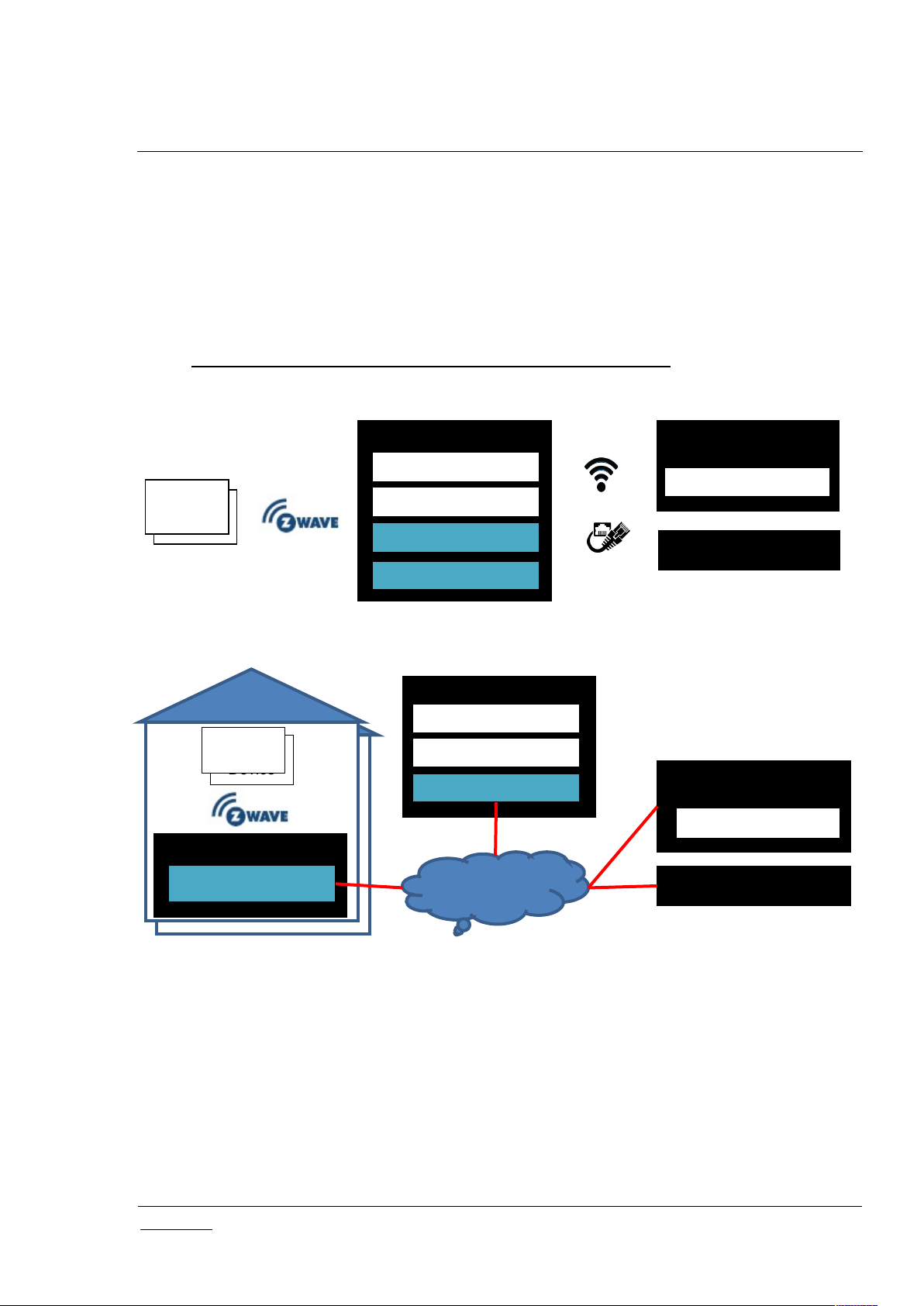
Z-Ware is a Z-Wave controller middleware running over a Z-Wave over IP (Z/IP) Gateway (ZIPGW) as a
Web Gateway. Z-Ware Apps (Z-Apps) are Web pages built into the Z-Ware Web Server providing UI for
phones and tablets/PCs. Z-Ware can be run in either Consumer Electronic (CE) on RPi3B+ (Raspberry Pi
3 – see https://www.raspberrypi.org/products/raspberry-pi-3-model-b-plus/) platform in the home or
Portal mode on a Linux Virtual Machine (VM) in the Cloud as shown below.
Figure 1: Z-Ware CE Running within a Home on RPi3B+
Figure 2: Z-Ware Portal in the Cloud Connected to Multiple Homes
This document covers the usage of Z-Ware Web Server and Apps for both CE and Portal and will
explicitly state if instructions are for any particular mode.
The diagrams shown in this guide are for Windows® OS with Internet Explorer 8 unless otherwise
specified. Your experience may vary slightly depending on your platform configuration.

INS14428-10 Z-Ware SDK 7.13.0 Web User Guide 2019-12-06
silabs.com | Building a more connected world.
Page 2 of 73
1.2 Audience and Requirements
Z-Wave Web users

INS14428-10 Z-Ware SDK 7.13.0 Web User Guide 2019-12-06
silabs.com | Building a more connected world.
Page 3 of 73
2 OVERVIEW
CC
VerCCVer
ASSOCIATION
3
PROTECTION
2
ASSOCIATION_GRP_INFO
3
SECURITY
1
BARRIER_OPERATOR
1
SECURITY 2
1
BASIC
2
SENSOR_BINARY
2
BATTERY
2
SENSOR_MULTILEVEL
11
CENTRAL_SCENE
3
SOUND_SWITCH
2
CONFIGURATION
4
SWITCH_BINARY
2
DOOR_LOCK
4
SWITCH_COLOR
3
DOOR_LOCK_LOGGING
1
SWITCH_MULTILEVEL
4
FIRMWARE_UPDATE_MD
7
THERMOSTAT_FAN_MODE
5
INDICATOR
3
THERMOSTAT_FAN_STATE
2
MANUFACTURER_SPECIFIC
2
THERMOSTAT_MODE
3
METER
5
THERMOSTAT_OPERATING_STATE
2
MULTI_CHANNEL
4
THERMOSTAT_SETPOINT
3
MULTI_CHANNEL_ASSOCIATION
4
TIME
2
NW_MGMT_BASIC
2
USER_CODE
2
NW_MGMT_INCLUSION
3
VERSION
3
NW_MGMT_INSTALLATION_MAINTENANCE
2
WAKE_UP
2
NW_MGMT_PROXY
2
WINDOW_COVERING
1
NODE_NAMING
1
ZIP_GATEWAY
1
NODE_PROVISIONING*
1
ZIP_PORTAL
1
NOTIFICATION/ALARM
8
ZWAVEPLUS_INFO
2
CC
VerCCVer
ALARM SENSOR
1
NO_OPERATION
1
APPLICATION_STATUS
1
POWERLEVEL
1
CRC_16_ENCAP
1
SUPERVISION
1
DEVICE_RESET_LOCALLY
1
ZIP
5
2.1 Z-Ware Library
The Z-Ware Library, which abstracts the ZIPGW, provides Z-Wave Command Class (CC) level APIs and
discovery of device capability and state. It is statically linked into the Z-Ware Web Server and provides
the following features. Please see [2] Silicon Labs, INS14606, INS, Z-Ware Library User Guide for details
on the Library behavior that affects the Web Server.
2.2 CC Control
Z-Ware controls the following CCs and versions:
Table 1: UI-Controlled Z-Wave CCs
Table 2: Controlled Z-Wave CCs Inherited through Library

INS14428-10 Z-Ware SDK 7.13.0 Web User Guide 2019-12-06
silabs.com | Building a more connected world.
Page 4 of 73
MULTI_CMD
1
ZIP_ND
1
2.3 CC Support
CC
Ver
Not
added
Non-secure
added
Securely
added
ASSOCIATION
3XXXASSOCIATION_GRP_INFO
3XXXDEVICE_RESET_LOCALLY
1XXXMULTICHANNEL_ASSOCIATION
4XX
X
CC
Ver
Not
added
Non-secure
added
Securely
added
APPLICATION_STATUS
1XX
CRC_16_ENCAP
1XX
FIRMWARE_UPDATE_MD
5XINCLUSION_CONTROLLER
1
1XX
INDICATOR
3XXXMAILBOX
3
2XMANUFACTURER_SPECIFIC
2XXXMULTI_CMD
1XX
NODE PROVISIONING
2
1XNW_MGMT_BASIC
2XNW_MGMT_INCLUSION
1
3XNW_MGMT_INSTALLATION_MAINTENANCE
2XNW_MGMT_PROXY
3XPOWERLEVEL
1XXXSECURITY
1XSECURITY_2
1XX
SUPERVISION
1XX
TRANSPORT_SERVICE
2XX
TIME
1XX
VERSION
3XXXZIP
3
5XZIP GATEWAY
3
1XZIP_ND
3
1
X
Z-Ware does nothing on receiving Basic CC Set or Get, unless Basic Set from any particular node or
endpoint is used as a Scene trigger. Z-Ware supports only 1 Association group supporting 1 node for
Lifeline. This node will receive the Device Reset Locally command.
For easier reference during certification, the associated ZIPGW supported CCs are shown below.
Table 3: Supported Z-Wave CCs Pushed down from Z-Ware
Table 4: ZIPGW SDK 7.13 Supported Z-Wave CCs
INS14428-10 Z-Ware SDK 7.13.0 Web User Guide 2019-12-06
silabs.com | Building a more connected world.
Page 5 of 73
ZIP NAMING
3
1XZIP PORTAL
3
1XZWAVEPLUS_INFO
2XX
1
CC
Command(s)
BASIC
SET
SWITCH_BINARY
SET
SWITCH_MULTILEVEL
SET, START_LEVEL_CHANGE
SWITCH_COLOR
SET
DOOR_LOCK
OPERATION_SET
BARRIER_OPERATOR
SET
THERMOSTAT_SETPOINT
SET
THERMOSTAT_MODE
SET
SOUND_SWITCH
TONE_PLAY_SET
WINDOW_COVERING
SET, START_LEVEL_CHANGE
CC
Command
Scene
Security
Arm/Disarm
Security
Alarm
BASIC
SETYY
SENSOR_BINARY
REPORTYY
SENSOR_MULTILEVEL
REPORT
Y
NOTIFICATION
REPORTYY
INCLUSION_CONTROLLER and NW_MGMT_INCLUSION CCs are only present when inclusion controller.
2
NODE_PROVISIONING is only present when SIS.
3
CCs only present on LAN NIF
2.4 Scenes
A Z-Ware Scene is a set of actions that may be activated by triggers. An action is a Z-Wave SET
command, such as turning on a switch. A trigger may be a user request through a UI element, by
schedule, or on an event. A schedule can be set to execute a Scene on any or every day of the week at a
preset time. A schedule remains active until it is disabled or deleted. An event refers to the receipt of a
Z-Wave report, typically a sensor report, such as motion sensed. The scene state, i.e., whether it is
completely activated, can also be monitored.
A Z-Ware Security Scene is a special Scene that can be armed or disarmed by an event trigger or
through the UI. It can only be alarmed when it is armed. When alarmed, it can send out alerts using
email and/or SMS. Arming, disarming, and alarming can also be configured to activate normal scenes.
The CCs and commands supported for Scenes actions and triggers are shown below. For Central Scene
CC, only the Key Pressed attribute is used.
Table 5: Scenes Actions Supported
Table 6: Scenes Event Triggers Supported

INS14428-10 Z-Ware SDK 7.13.0 Web User Guide 2019-12-06
silabs.com | Building a more connected world.
Page 6 of 73
DOOR_LOCK
REPORTYY
CENTRAL_SCENE
NOTIFICATION
Y
Y
2.5 Bundled Z-Ware Apps
UI
Base URI or location
Tablet/PC Web
/ui/pc/index.html
Phone Web
/ui/phone/index.html
Engineering Web
/ui/eng/index.html
iOS Native
https://itunes.apple.com/app/z-wave/id1427154750
Android Native
https://play.google.com/store/apps/details?id=com.silabs.zware7app
Consumer-friendly UIs targeted for Tablet/PC and Phone are included, as well as an Engineering version
to demonstrate the server’s capabilities.
Table 7: Bundled Z-Ware Apps and URIs
On Web login, the Tablet or Phone UI is automatically selected by the server based on the User Agent of
the Web browser used.
Scanning of QR code is only available in the Native UIs.
Users can build custom apps over the Z-Ware Web API – see [1].

INS14428-10 Z-Ware SDK 7.13.0 Web User Guide 2019-12-06
silabs.com | Building a more connected world.
Page 7 of 73
3 ACCESS
3.1 Login
3.2 CE
CE users access their accounts on the machine they have installed at https://<machine IP address>. The
default username and password are ‘user’ and ‘smarthome’ respectively. The page will be titled “CE”
instead of “Portal” and the links at the bottom will not be there.
3.3 Portal
Z-Ware Portal users access their accounts at https://z-ware.silabs.com. They can log in and create their
account or reset the account password through the links at the bottom.
Figure 3: Login Page
INS14428-10 Z-Ware SDK 7.13.0 Web User Guide 2019-12-06
silabs.com | Building a more connected world.
Page 8 of 73
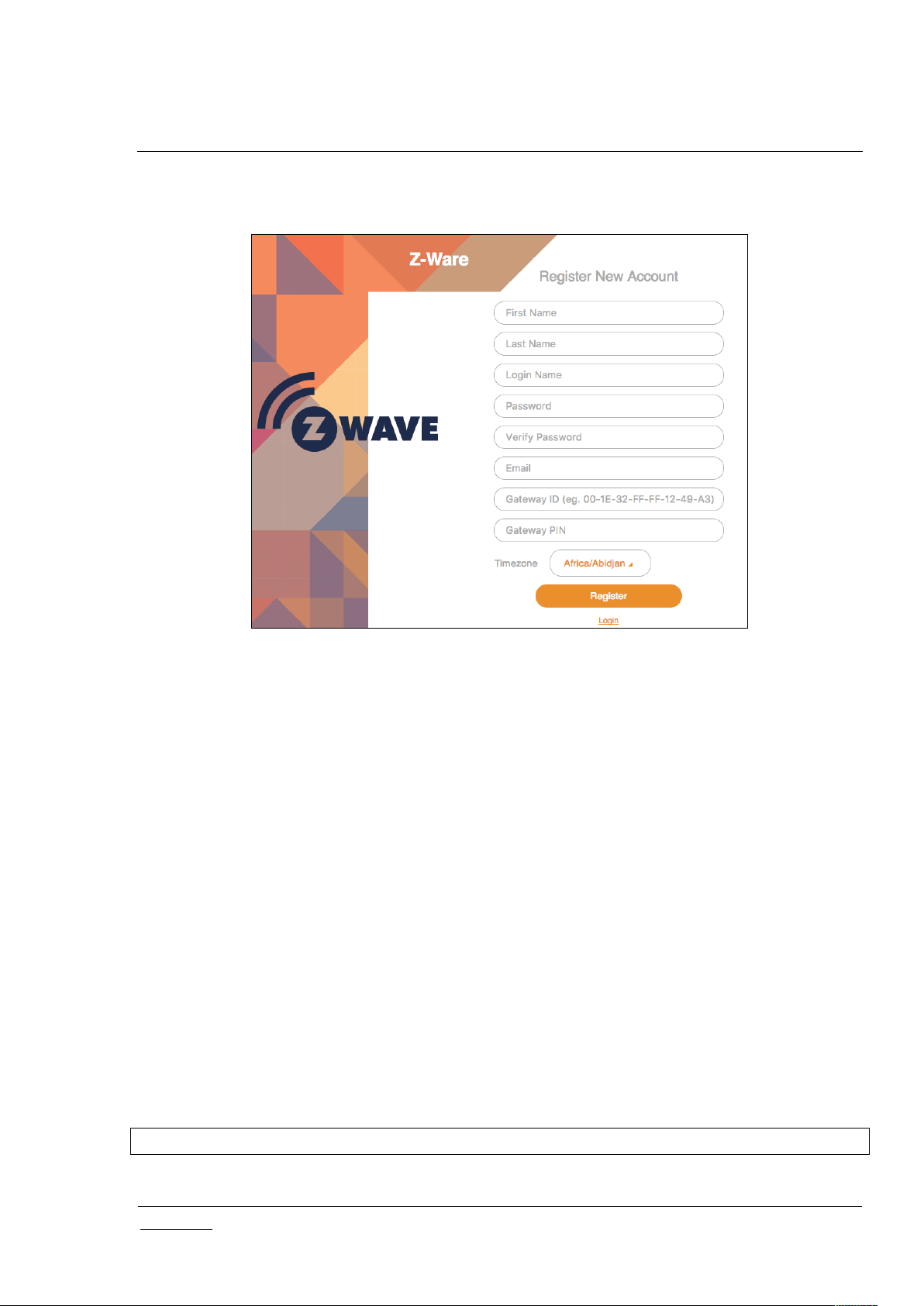
3.3.1 Registration
To create the Portal account, fill in the registration details.
Figure 4: Portal Registration Page
First and last names are alphabetical only and between 3 to 25 characters in length. A username is of
the same length but can be alphanumeric, in addition supporting both ‘_’ (underscore) and ‘.’ (period)
special characters. A password must be between 8 to 16 characters in length.
The Gateway ID is the ZIPGW platform Ethernet MAC address which can be obtained as specified in the
ZIPGW documentation. The PIN should be left blank during the initial registration. The time zone setting
allows the server to convert time information to match the locality of the ZIPGW.
On registration, an email is sent to the registered email address, which contains an unregister link if the
user entered incorrect details and wishes to reregister and a link to download certificates to the ZIPGW
platform, as specified in the ZIPGW documentation. A PIN is also generated which can be used for
subsequent registration when the Portal is changed.
3.3.2 ZIPGW Configuration
ZIPGW on the RPi3B+ needs to be configured, via ssh/scp access from a host machine, to use the ZWare Portal.
3.3.2.1 Obtaining Ethernet MAC address of ZIPGW
Search the MAC address in ZIPGW log file at /var/log/zipgateway.log on RPi3B+.
# less /var/log/zipgateway.log | grep "L2 HW addr"
Or the MAC address can be seen in the beginning of log file as marked below:

INS14428-10 Z-Ware SDK 7.13.0 Web User Guide 2019-12-06
silabs.com | Building a more connected world.
Page 9 of 73
Figure 5: ZIPGW MAC Address
To convert the MAC in MAC-48 format to the RAC in EUI-64, the colons need to be changed to dashes,
the letter capitalized and ‘FF-FF’ needs to be inserted in the middle. For eg:
00:1e:32:11:4c:92 -> 00-1E-32-FF-FF-11-4C-92
3.3.2.2 Downloading certificates
On the host machine, copy (scp) the certificates to RPi3B+:
$ scp ZIPR.key_1024.pem ZIPR.x509_1024.pem pi@<ipaddress>:/tmp
Move the files on RPi3B+ to /usr/local/etc:
# sudo mv /tmp/ZIPR.key_1024.pem /usr/local/etc/
# sudo mv /tmp/ZIPR.x509_1024.pem /usr/local/etc/
Make sure that the configuration variables ZipPrivKey and ZipCert in the ZIPGW configuration file
/usr/local/etc/zipgateway.cfg, mention the path respectively to those files as shown below.
ZipPrivKey=/usr/local/etc/ZIPR.key_1024.pem
ZipCert=/usr/local/etc/ZIPR.x509_1024.pem
Verify the configuration variables:
# less /usr/local/etc/zipgateway.cfg | grep ZipPrivKey

INS14428-10 Z-Ware SDK 7.13.0 Web User Guide 2019-12-06
silabs.com | Building a more connected world.
Page 10 of 73
# less /usr/local/etc/zipgateway.cfg | grep ZipCert
3.3.2.3 Configuring for Portal
By default, the image is set for the ZIPGW to connect to Z-Ware CE on the board. To modify it to
connect to Z-Ware Portal, ensure that /usr/local/etc/zipgateway.cfg has the following lines:
ZipPortal=z-ware.silabs.com
ZipPortalPort=44123
Reboot once the change is made.
3.3.3 Reset Password
The Portal account name needs to be specified to confirm a password reset. An email will be sent with
an unregister link, and the process will be the same as creating a new account.
Figure 6: Portal Reset Password Page

INS14428-10 Z-Ware SDK 7.13.0 Web User Guide 2019-12-06
silabs.com | Building a more connected world.
Page 11 of 73
4 TABLET/PC AND PHONE UI
Tablet and Phone UI are essentially the same except for layout differences. For the Tablet UI, the main
menu appears on the left while for the Phone UI, it appears at the bottom. On the top right, for the
Portal version only, an icon shows the connection to the portal, blue when connected, grey otherwise.
Users can also log out on the top right of the Tablet UI.
4.1 Scenes
The scenes page allows monitoring, manual activation, and editing of a list of scenes. For more
information on Scenes, see Section 2.4 Scenes.
Normal scenes can be manually activated by the play icon. Security scenes can be armed or disarmed
with the bell or crossed bell icons respectively. Normal Scenes in active state and Security scenes in
armed state are shown in orange while others are in grey.
New scenes can be created with the ‘Scenes +’ and Security Scenes +’ links. Clicking on a scene will
enter the summary page.
All scenes have a clapper board icon, and those that have configured schedule or event triggers have a
clock superimposed on the icon. Security Scenes have a bell superimposed on the icon. The turning
wheel at the top right indicates that the scenes are updating their status. Scene status is updated only
when Home or Scenes buttons are clicked, or when a scene is triggered. Clicking on a scene triggers it
Figure 7: Tab UI - Scenes

INS14428-10 Z-Ware SDK 7.13.0 Web User Guide 2019-12-06
silabs.com | Building a more connected world.
Page 12 of 73
manually, turning its tab blue and starting the status update. If, for some reason, it is not activated, it
returns to its original color. As the same devices may be activated by multiple scenes, triggering 1 scene
may affect the state of multiple scenes. The “Toggle View” button, only on the Tablet UI, can switch the
scenes arrangement to columns and rows, instead of just 1 column.
Figure 8: Tab UI - Scenes Edit

INS14428-10 Z-Ware SDK 7.13.0 Web User Guide 2019-12-06
silabs.com | Building a more connected world.
Page 13 of 73
Figure 9: Tab UI - Scenes Toggle
4.1.1 Scene Summary
When a preconfigured scene is viewed by clicking on it or a new scene created by clicking on the ‘+
SCENE’ button, the summary is shown which condenses the associated schedules, triggers, and actions
into 1 page. For a new scene, these will be empty and need to be configured. The scene can be deleted
using the DELETE link and renamed in the Name text box. The tabs are for editing and viewing details
for Schedule, Trigger, and Action.

INS14428-10 Z-Ware SDK 7.13.0 Web User Guide 2019-12-06
silabs.com | Building a more connected world.
Page 14 of 73
Figure 10: Tab UI: Scene View Summary
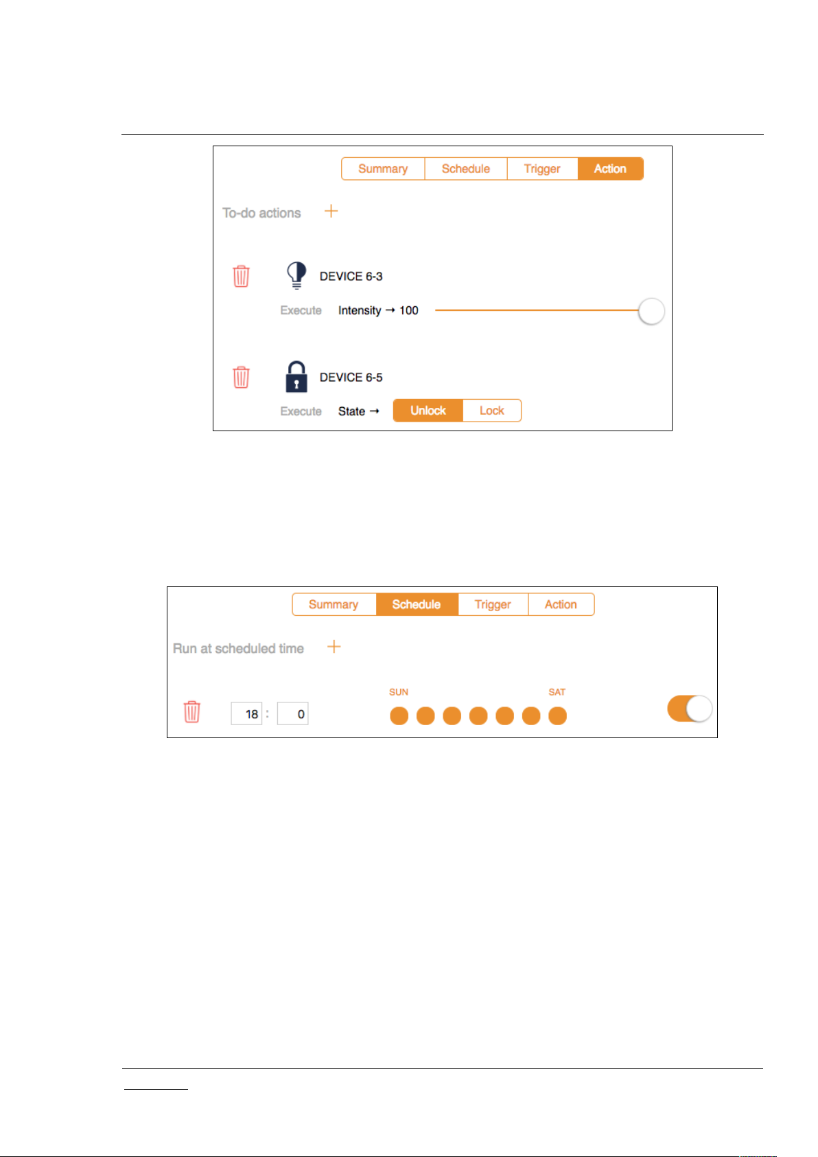
4.1.2 Scene Action
When the action tab is clicked, associated actions are shown and may be edited or deleted. If there is
only 1 action, it cannot be deleted until another is added as a scene needs to have at least 1 action.
More actions can be added with the “To do actions +” link, whereby a pop up of device endpoints with
known controllable interfaces will be shown followed by those that can only be controlled with a Basic
Set. After the endpoint is selected, the interface needs to be selected as well. The value to set can then
be configured on the page itself.
INS14428-10 Z-Ware SDK 7.13.0 Web User Guide 2019-12-06
silabs.com | Building a more connected world.
Page 15 of 73
Figure 11: Tab UI - Scene View Action
4.1.3 Scene Schedule
The Scene schedule tab shows the schedule which can viewed and edited. A schedule is created using
the ‘Run at scheduled time +’ link. The schedule is set to a selected time of day for selected days of the
week and can be enabled/disabled or deleted.
Figure 12: Tab UI - Scene Schedule
4.1.4 Scene Trigger
The scene trigger tab shows the triggers which can be viewed and edited. The trigger can be enabled,
disabled, or deleted.
New triggers can be added with the ‘run this scene when +’ link starting a 3-stage process. Device
endpoints with known reports will be listed in a pop up before device endpoints that may only send a
Basic Set. Similar to actions, a device endpoint, interface, such as a multi-level sensor, and an interface
subtype, such as the temperature sensor, must be selected. The value for triggering can then be
configured on the page itself.

INS14428-10 Z-Ware SDK 7.13.0 Web User Guide 2019-12-06
silabs.com | Building a more connected world.
Page 16 of 73
Figure 13: Tab UI - Scene Trigger
4.1.5 Security Scene Summary
Similar to a scene, when a security scene is selected or created, the summary page is shown.
4.1.6 Security Scene Arming
Users see the following when selecting the ‘Arm Automation’ tab.
Figure 14: Tab UI - Security Scene Summary
 Loading...