

Page 1
Digital flatbed cutter
G3 series
(M-1600, M-2500, L-2500, L-3200, XL-1600, XL-3200, 2XL-1600, 2XL-3200, 3XL-1600, 3XL-3200)
Operating manual
EN
Page 2

Original operating instructions
Author Technical Communications
Department, Zünd Systemtechnik AG
Composition and publication Zünd Systemtechnik AG
Copyright
©
Version:
Menu version:
Date:
Doc. no.:
Zünd Systemtechnik AG
09
1.45
05-2010
5106015
Page 3

G3 series
0
Contents
1 Introduction . . . . . . . . . . . . . . . . . . . . . . . . . . . . . . . . . . . . . . . . . . . . . . . . . 1
1.1 Foreword . . . . . . . . . . . . . . . . . . . . . . . . . . . . . . . . . . . . . . . . . . . . . . . . . . . 1
1.2 Using the documentation . . . . . . . . . . . . . . . . . . . . . . . . . . . . . . . . . . . . . . 2
1.2.1 Structure of the operating manual . . . . . . . . . . . . . . . . . . . . . . . . . . . . . . . 2
1.2.2 Symbols . . . . . . . . . . . . . . . . . . . . . . . . . . . . . . . . . . . . . . . . . . . . . . . . . . . 3
1.3 Points to note when reading this operating manual . . . . . . . . . . . . . . . . . . 4
1.4 Care of the documentation . . . . . . . . . . . . . . . . . . . . . . . . . . . . . . . . . . . . . 4
1.5 Current status of documentation . . . . . . . . . . . . . . . . . . . . . . . . . . . . . . . . . 5
1.6 Standardisation, tests, marking . . . . . . . . . . . . . . . . . . . . . . . . . . . . . . . . . 5
1.6.1 Standards . . . . . . . . . . . . . . . . . . . . . . . . . . . . . . . . . . . . . . . . . . . . . . . . . . 5
1.6.2 CE marking . . . . . . . . . . . . . . . . . . . . . . . . . . . . . . . . . . . . . . . . . . . . . . . . . 5
1.6.3 UL testing . . . . . . . . . . . . . . . . . . . . . . . . . . . . . . . . . . . . . . . . . . . . . . . . . . 6
1.7 Legal notice . . . . . . . . . . . . . . . . . . . . . . . . . . . . . . . . . . . . . . . . . . . . . . . . 7
1.8 Troubleshooting, hints and tips . . . . . . . . . . . . . . . . . . . . . . . . . . . . . . . . . . 7
1.9 Documented cutter models . . . . . . . . . . . . . . . . . . . . . . . . . . . . . . . . . . . . . 7
1.10 Publishing details . . . . . . . . . . . . . . . . . . . . . . . . . . . . . . . . . . . . . . . . . . . . 7
2 Product description . . . . . . . . . . . . . . . . . . . . . . . . . . . . . . . . . . . . . . . . . . .1
2.1 General . . . . . . . . . . . . . . . . . . . . . . . . . . . . . . . . . . . . . . . . . . . . . . . . . . . . 1
2.2 Product identification . . . . . . . . . . . . . . . . . . . . . . . . . . . . . . . . . . . . . . . . . 2
2.2.1 Rating plate . . . . . . . . . . . . . . . . . . . . . . . . . . . . . . . . . . . . . . . . . . . . . . . . . 2
2.2.2 UL marking . . . . . . . . . . . . . . . . . . . . . . . . . . . . . . . . . . . . . . . . . . . . . . . . . 3
2.3 Intended use . . . . . . . . . . . . . . . . . . . . . . . . . . . . . . . . . . . . . . . . . . . . . . . . 3
2.4 Cutter - overview . . . . . . . . . . . . . . . . . . . . . . . . . . . . . . . . . . . . . . . . . . . . . 4
2.5 Modules, tools . . . . . . . . . . . . . . . . . . . . . . . . . . . . . . . . . . . . . . . . . . . . . . . 5
2.5.1 General . . . . . . . . . . . . . . . . . . . . . . . . . . . . . . . . . . . . . . . . . . . . . . . . . . . . 5
2.5.2 UM . . . . . . . . . . . . . . . . . . . . . . . . . . . . . . . . . . . . . . . . . . . . . . . . . . . . . . . 5
2.5.2.1
2.5.3 RM-A . . . . . . . . . . . . . . . . . . . . . . . . . . . . . . . . . . . . . . . . . . . . . . . . . . . . . . 7
2.5.4 PUM . . . . . . . . . . . . . . . . . . . . . . . . . . . . . . . . . . . . . . . . . . . . . . . . . . . . . . 7
2.5.5 MAM-S/D . . . . . . . . . . . . . . . . . . . . . . . . . . . . . . . . . . . . . . . . . . . . . . . . . . 8
2.6 Material handling, options . . . . . . . . . . . . . . . . . . . . . . . . . . . . . . . . . . . . . . 9
2.6.1 Laser pointer . . . . . . . . . . . . . . . . . . . . . . . . . . . . . . . . . . . . . . . . . . . . . . . . 9
2.6.2 ICC camera . . . . . . . . . . . . . . . . . . . . . . . . . . . . . . . . . . . . . . . . . . . . . . . . . 9
2.6.3 Cutter with static work surface . . . . . . . . . . . . . . . . . . . . . . . . . . . . . . . . . . 9
2.6.4 Cutter with conveyor . . . . . . . . . . . . . . . . . . . . . . . . . . . . . . . . . . . . . . . . . 10
2.6.5 Sheet feeder options . . . . . . . . . . . . . . . . . . . . . . . . . . . . . . . . . . . . . . . . . 10
2.6.6 Drip tray . . . . . . . . . . . . . . . . . . . . . . . . . . . . . . . . . . . . . . . . . . . . . . . . . . 11
2.7 Technical description . . . . . . . . . . . . . . . . . . . . . . . . . . . . . . . . . . . . . . . . 12
2.7.1 Complete machine . . . . . . . . . . . . . . . . . . . . . . . . . . . . . . . . . . . . . . . . . . 12
2.7.2 Schedule of work sequences . . . . . . . . . . . . . . . . . . . . . . . . . . . . . . . . . . 12
2.7.3 Complete machine . . . . . . . . . . . . . . . . . . . . . . . . . . . . . . . . . . . . . . . . . . 13
2.7.4 Movement system . . . . . . . . . . . . . . . . . . . . . . . . . . . . . . . . . . . . . . . . . . . 14
2.7.5 Processing materials . . . . . . . . . . . . . . . . . . . . . . . . . . . . . . . . . . . . . . . . 15
2.8 Technical information . . . . . . . . . . . . . . . . . . . . . . . . . . . . . . . . . . . . . . . . 16
2.8.1 Dimensions and weights . . . . . . . . . . . . . . . . . . . . . . . . . . . . . . . . . . . . . . 16
2.8.1.1
2.8.1.2
2.8.2 Electrical connection, power consumption . . . . . . . . . . . . . . . . . . . . . . . . 19
Tools for the UM
Basic device
. . . . . . . . . . . . . . . . . . . . . . . . . . . . . . . . . . . . . . . . . . . . . . . 16
Cutter extension
. . . . . . . . . . . . . . . . . . . . . . . . . . . . . . . . . . . . . . . . . . . . . 6
. . . . . . . . . . . . . . . . . . . . . . . . . . . . . . . . . . . . . . . . . . . . 18
000017,03,06-2009, jmu
0-1
Page 4

0
G3 series
2.8.3 Environmental conditions . . . . . . . . . . . . . . . . . . . . . . . . . . . . . . . . . . . . . 19
2.8.4 Basic device compressed air . . . . . . . . . . . . . . . . . . . . . . . . . . . . . . . . . . 19
2.8.5 Control unit . . . . . . . . . . . . . . . . . . . . . . . . . . . . . . . . . . . . . . . . . . . . . . . . 20
2.8.6 Performance . . . . . . . . . . . . . . . . . . . . . . . . . . . . . . . . . . . . . . . . . . . . . . . 21
2.8.7 Emissions . . . . . . . . . . . . . . . . . . . . . . . . . . . . . . . . . . . . . . . . . . . . . . . . . 22
2.8.8 FCC approval . . . . . . . . . . . . . . . . . . . . . . . . . . . . . . . . . . . . . . . . . . . . . . 22
3 Safety . . . . . . . . . . . . . . . . . . . . . . . . . . . . . . . . . . . . . . . . . . . . . . . . . . . . .1
3.1 General . . . . . . . . . . . . . . . . . . . . . . . . . . . . . . . . . . . . . . . . . . . . . . . . . . . . 1
3.2 Proper use . . . . . . . . . . . . . . . . . . . . . . . . . . . . . . . . . . . . . . . . . . . . . . . . . 2
3.3 Examples of improper use . . . . . . . . . . . . . . . . . . . . . . . . . . . . . . . . . . . . . 2
3.4 Hazard warnings, important instructions . . . . . . . . . . . . . . . . . . . . . . . . . . . 3
3.4.1 Explanation of the hazard warning . . . . . . . . . . . . . . . . . . . . . . . . . . . . . . . 3
3.4.2 Structure of the hazard warnings . . . . . . . . . . . . . . . . . . . . . . . . . . . . . . . . 4
3.5 Areas of responsibility . . . . . . . . . . . . . . . . . . . . . . . . . . . . . . . . . . . . . . . . . 5
3.6 Personnel requirements . . . . . . . . . . . . . . . . . . . . . . . . . . . . . . . . . . . . . . . 5
3.7 Rules and safety at work . . . . . . . . . . . . . . . . . . . . . . . . . . . . . . . . . . . . . . . 6
3.8 Procedure in case of malfunctions . . . . . . . . . . . . . . . . . . . . . . . . . . . . . . . 6
3.9 Danger areas . . . . . . . . . . . . . . . . . . . . . . . . . . . . . . . . . . . . . . . . . . . . . . . 7
3.9.1 General danger area . . . . . . . . . . . . . . . . . . . . . . . . . . . . . . . . . . . . . . . . . . 7
3.9.2 Danger area on the module carriage . . . . . . . . . . . . . . . . . . . . . . . . . . . . . 8
3.9.3 Danger area during the installation . . . . . . . . . . . . . . . . . . . . . . . . . . . . . . . 9
3.10 Working and traffic area . . . . . . . . . . . . . . . . . . . . . . . . . . . . . . . . . . . . . . 10
3.11 Safety signs . . . . . . . . . . . . . . . . . . . . . . . . . . . . . . . . . . . . . . . . . . . . . . . 11
3.11.1 Responsibility of the operator . . . . . . . . . . . . . . . . . . . . . . . . . . . . . . . . . . 11
3.11.2 Position of the safety signs . . . . . . . . . . . . . . . . . . . . . . . . . . . . . . . . . . . . 11
3.12 Safety and monitoring devices . . . . . . . . . . . . . . . . . . . . . . . . . . . . . . . . . 14
3.12.1 Protective system . . . . . . . . . . . . . . . . . . . . . . . . . . . . . . . . . . . . . . . . . . . 15
3.12.2 Operating unit . . . . . . . . . . . . . . . . . . . . . . . . . . . . . . . . . . . . . . . . . . . . . . 15
3.12.3 Emergency stop switch . . . . . . . . . . . . . . . . . . . . . . . . . . . . . . . . . . . . . . . 16
3.12.4 Safety cut-off feature . . . . . . . . . . . . . . . . . . . . . . . . . . . . . . . . . . . . . . . . . 16
3.13 Personal protective equipment, clothing . . . . . . . . . . . . . . . . . . . . . . . . . . 17
3.14 Mechanical hazards . . . . . . . . . . . . . . . . . . . . . .
3.14.1 Gathering, retraction . . . . . . . . . . . . . . . . . . . . . . . . . . . . . . . . . . . . . . . . . 18
3.14.2 Gathering, impacts of foreign objects . . . . . . . . . . . . . . . . . . . . . . . . . . . . 18
3.14.3 Cuts and stab wounds . . . . . . . . . . . . . . . . . . . . . . . . . . . . . . . . . . . . . . . 19
3.15 Risk of burns . . . . . . . . . . . . . . . . . . . . . . . . . . . . . . . . . . . . . . . . . . . . . . . 19
3.16 Electrical hazard . . . . . . . . . . . . . . . . . . . . . . . . . . . . . . . . . . . . . . . . . . . . 20
3.17 Risks arising from the emission of toxic dust . . . . . . . . . . . . . . . . . . . . . . 21
3.18 Risks arising from the processing of toxic/hazardous materials . . . . . . . . 21
3.19 Environmental hazard . . . . . . . . . . . . . . . . . . . . . . . . . . . . . . . . . . . . . . . . 22
3.20 Handling and storage of chemicals . . . . . . . . . . . . . . . . . . . . . . . . . . . . . . 23
3.21 Risk of fire and explosion . . . . . . . . . . . . . . . . . . . . . . . . . . . . . . . . . . . . . 24
3.22 Danger caused by laser beam (laser pointer) . . . . . . . . . . . . . . . . . . . . . . 25
3.23 Safety instructions for operators . . . . . . . . . . . . . . . . . . . . . . . . . . . . . . . . 25
3.24 Safety precautions for service personnel . . . . . . . . . . . . . . . . . . . . . . . . . 26
3.25 Disposal . . . . . . . . . . . . . . . . . . . . . . . . . . . . . . . . . . . . . . . . . . . . . . . . . . 26
. . . . . . . . . . . . . . . . . . . 18
0-2
000017,03,06-2009, jmu
Page 5

G3 series
4 Controls and operation . . . . . . . . . . . . . . . . . . . . . . . . . . . . . . . . . . . . . . . . 1
4.1 General . . . . . . . . . . . . . . . . . . . . . . . . . . . . . . . . . . . . . . . . . . . . . . . . . . . . 1
4.2 Safe working practices . . . . . . . . . . . . . . . . . . . . . . . . . . . . . . . . . . . . . . . . 1
4.3 Controls . . . . . . . . . . . . . . . . . . . . . . . . . . . . . . . . . . . . . . . . . . . . . . . . . . . 2
4.3.1 Control panel . . . . . . . . . . . . . . . . . . . . . . . . . . . . . . . . . . . . . . . . . . . . . . . 2
4.3.1.1
4.3.1.2
4.3.1.3
4.3.1.4
4.3.1.5
4.3.1.6
4.3.1.7
4.3.2 Emergency stop switches . . . . . . . . . . . . . . . . . . . . . . . . . . . . . . . . . . . . . . 7
4.3.3 Maintenance unit . . . . . . . . . . . . . . . . . . . . . . . . . . . . . . . . . . . . . . . . . . . . 9
4.3.4 Interfaces . . . . . . . . . . . . . . . . . . . . . . . . . . . . . . . . . . . . . . . . . . . . . . . . . 10
4.4 Menu navigation . . . . . . . . . . . . . . . . . . . . . . . . . . . . . . . . . . . . . . . . . . . . 11
4.4.1 Menus and functions . . . . . . . . . . . . . . . . . . . . . . . . . . . . . . . . . . . . . . . . . 11
4.4.2 Help . . . . . . . . . . . . . . . . . . . . . . . . . . . . . . . . . . . . . . . . . . . . . . . . . . . . . 13
4.4.3 Info menu . . . . . . . . . . . . . . . . . . . . . . . . . . . . . . . . . . . . . . . . . . . . . . . . . 13
4.4.4 Popups/dialogues . . . . . . . . . . . . . . . . . . . . . . . . . . . . . . . . . . . . . . . . . . . 13
4.4.5 User level . . . . . . . . . . . . . . . . . . . . . . . . . . . . . . . . . . . . . . . . . . . . . . . . . 14
4.4.6 Function keys . . . . . . . . . . . . . . . . . . . . . . . . . . . . . . . . . . . . . . . . . . . . . . 15
4.5 Functions . . . . . . . . . . . . . . . . . . . . . . . . . . . . . . . . . . . . . . . . . . . . . . . . . 16
4.5.1 Set language . . . . . . . . . . . . . . . . . . . . . . . . . . . . . . . . . . . . . . . . . . . . . . . 16
4.5.2 Set display . . . . . . . . . . . . . . . . . . . . . . . . . . . . . . . . . . . . . . . . . . . . . . . . 16
4.5.3 Setting the volume of the signal . . . . . . . . . . . . . . . . . . . . . . . . . . . . . . . . 16
4.5.4 Delete data buffer . . . . . . . . . . . . . . . . . . . . . . . . . . . . . . . . . . . . . . . . . . . 16
4.6 Operation . . . . . . . . . . . . . . . . . . . . . . . . . . . . . . . . . . . . . . . . . . . . . . . . . 17
4.6.1 Daily checks prior to start-up . . . . . . . . . . . . . . . . . . . . . . . . . . . . . . . . . . 17
4.6.2 Start-up . . . . . . . . . . . . . . . . . . . . . . . . . . . . . . . . . . . . . . . . . . . . . . . . . . . 18
4.6.3 Operating status . . . . . . . . . . . . . . . . . . . . . . . . . . . . . . . . . . . . . . . . . . . . 20
4.6.3.1
4.6.3.2
4.6.3.3
4.6.4 Moving the bar/module manually . . . . . . . . . . . . . . . . . . . . . . . . . . . . . . . 23
4.7 Handling modules/tools . . . . . . . . . . . . . . . . . . . . . . . . . . . . . . . . . . . . . . 24
4.7.1 Module/tool/tool insert . . . . . . . . . . . . . . . . . . . . . . . . . . . . . . . . . . . . . . . . 25
4.7.2 Set module/tool change position . . . . . . . . . . . . . . . . . . . . . . . . . . . . . . . . 26
4.7.3 Inserting/replacing the module . . . . . . . . . . . . . . . . . . . . . . . . . . . . . . . . . 27
4.7.3.1
4.7.3.2
4.7.4 Activating a module . . . . . . . . . . . . . . . . . . . . . . . . . . . . . . . . . . . . . . . . . 29
4.7.5 Tool handling . . . . . . . . . . . . . . . . . . . . . . . . . . . . . . . . . . . . . . . . . . . . . . 30
4.7.5.1
4.7.5.2
4.7.5.3
4.7.6 Attaching/selecting a tool . . . . . . . . . . . . . . . . . . . . . . . . . . . . . . . . . . . . . 32
4.7.6.1
4.7.6.2
4.7.6.3
Operating unit
Navigation keys
Numerical keys
Function keys
Travel keys
Soft keys
Special keys, shortcuts
OFFLINE
STOPPED
ONLINE
Module mount
Inserting/replacing the module (e.g. UM)
Marking the tool (e.g.)
Switching the tool manager on/off
. . . . . . . . . . . . . . . . . . . . . . . . . . . . . . . . . . . . . . . . . . . . . . . 3
. . . . . . . . . . . . . . . . . . . . . . . . . . . . . . . . . . . . . . . . . . . . . 4
. . . . . . . . . . . . . . . . . . . . . . . . . . . . . . . . . . . . . . . . . . . . . . 4
. . . . . . . . . . . . . . . . . . . . . . . . . . . . . . . . . . . . . . . . . . . . . . . 4
. . . . . . . . . . . . . . . . . . . . . . . . . . . . . . . . . . . . . . . . . . . . . . . . . 5
. . . . . . . . . . . . . . . . . . . . . . . . . . . . . . . . . . . . . . . . . . . . . . . . . . . 5
. . . . . . . . . . . . . . . . . . . . . . . . . . . . . . . . . . . . . . . . 6
. . . . . . . . . . . . . . . . . . . . . . . . . . . . . . . . . . . . . . . . . . . . . . . . . . 21
. . . . . . . . . . . . . . . . . . . . . . . . . . . . . . . . . . . . . . . . . . . . . . . . . 21
. . . . . . . . . . . . . . . . . . . . . . . . . . . . . . . . . . . . . . . . . . . . . . . . . . 22
. . . . . . . . . . . . . . . . . . . . . . . . . . . . . . . . . . . . . . . . . . . . . . 27
. . . . . . . . . . . . . . . . . . . . . . . . . 28
. . . . . . . . . . . . . . . . . . . . . . . . . . . . . . . . . . . . . . . . 30
. . . . . . . . . . . . . . . . . . . . . . . . . . . . . . 30
Tool manager — change tool (UM module)
Creating a new tool
Selecting a tool
Deleting a tool
. . . . . . . . . . . . . . . . . . . . . . . . . . . . . . . . . . . . . . . . . . 32
. . . . . . . . . . . . . . . . . . . . . . . . . . . . . . . . . . . . . . . . . . . . . 32
. . . . . . . . . . . . . . . . . . . . . . . . . . . . . . . . . . . . . . . . . . . . . . 32
. . . . . . . . . . . . . . . . . . . . . . . 31
0
000017,03,06-2009, jmu
0-3
Page 6

0
G3 series
4.7.6.4
4.7.7 Inserting and connecting a tool (e.g. oscillating tool) . . . . . . . . . . . . . . . . 33
4.7.8 Connecting driven tools - allocating port . . . . . . . . . . . . . . . . . . . . . . . . . . 35
4.7.8.1
4.7.8.2
4.7.9 Tool positions . . . . . . . . . . . . . . . . . . . . . . . . . . . . . . . . . . . . . . . . . . . . . . 37
4.8 Material hold-down . . . . . . . . . . . . . . . . . . . . . . . . . . . . . . . . . . . . . . . . . . 38
4.8.1 Preparation . . . . . . . . . . . . . . . . . . . . . . . . . . . . . . . . . . . . . . . . . . . . . . . . 39
4.8.2 Defining/checking the vacuum range . . . . . . . . . . . . . . . . . . . . . . . . . . . . 40
4.8.3 Setting the strength . . . . . . . . . . . . . . . . . . . . . . . . . . . . . . . . . . . . . . . . . . 41
4.8.4 Switching on/off . . . . . . . . . . . . . . . . . . . . . . . . . . . . . . . . . . . . . . . . . . . . . 41
4.8.5 Working with air-permeable materials . . . . . . . . . . . . . . . . . . . . . . . . . . . . 41
4.9 Feeding options* . . . . . . . . . . . . . . . . . . . . . . . . . . . . . . . . . . . . . . . . . . . . 42
4.9.1 Feeding clamps . . . . . . . . . . . . . . . . . . . . . . . . . . . . . . . . . . . . . . . . . . . . . 43
4.9.2 Feed guide rail . . . . . . . . . . . . . . . . . . . . . . . . . . . . . . . . . . . . . . . . . . . . . 44
4.9.3 Feeding options . . . . . . . . . . . . . . . . . . . . . . . . . . . . . . . . . . . . . . . . . . . . 45
4.9.3.1
4.9.3.2
4.10 Automatic tool initialisation (AKI) . . . . . . . . . . . . . . . . . . . . . . . . . . . . . . . 46
4.10.1 Description . . . . . . . . . . . . . . . . . . . . . . . . . . . . . . . . . . . . . . . . . . . . . . . . 46
4.10.2 Adjusting the height . . . . . . . . . . . . . . . . . . . . . . . . . . . . . . . . . . . . . . . . . 47
4.10.3 Initialisation . . . . . . . . . . . . . . . . . . . . . . . . . . . . . . . . . . . . . . . . . . . . . . . . 48
4.11 Laser pointer, reference point . . . . . . . . . . . . . . . . . . . . . . . . . . . . . . . . . . 49
4.11.1 Laser pointer settings . . . . . . . . . . . . . . . . . . . . . . . . . . . . . . . . . . . . . . . . 49
4.11.2 Reference point settings . . . . . . . . . . . . . . . . . . . . . . . . . . . . . . . . . . . . . . 50
4.11.3 Choose laser pointer as pointer type . . . . . . . . . . . . . . . . . . . . . . . . . . . . 51
4.11.4 Define reference point . . . . . . . . . . . . . . . . . . . . . . . . . . . . . . . . . . . . . . . . 51
4.12 Material stop . . . . . . . . . . . . . . . . . . . . . . . . . . . . . . . . . . . . . . . . . . . . . . . 52
4.13 Module carriage slot protective plate . . . . . . . . . . . . . . . . . . . . . . . . . . . . 53
4.14 Module and tool holder* . . . . . . . . . . . . . . . . . . . . . . . . . . . . . . . . . . . . . . 54
4.15 Switch off the machine . . . . . . . . . . . . . . . . . . . . . . . . . . . . . . . . . . . . . . . 55
Saving tool-specific cutter settings
. . . . . . . . . . . . . . . . . . . . . . . . . . . . . . 32
Connection - electrical tools (EOT, DRT, etc.)
Connection - pneumatic tools
Automatic feed
Manual feed
. . . . . . . . . . . . . . . . . . . . . . . . . . . . . . . . . . . . . . . . . . . . . 45
. . . . . . . . . . . . . . . . . . . . . . . . . . . . . . . . . . . . . . . . . . . . . . . 45
. . . . . . . . . . . . . . . . . . . . . . . . . . . . . . . . . . 36
. . . . . . . . . . . . . . . . . . . . . 35
5 Description of menu . . . . . . . . . . . . . . . . . . . . . . . . . . . . . . . . . . . . . . . . . .1
5.1 General . . . . . . . . . . . . . . . . . . . . . . . . . . . . . . . . . . . . . . . . . . . . . . . . . . . . 1
5.2 Menu structure . . . . . . . . . . . . . . . . . . . . . . . . . . . . . . . . . . . . . . . . . . . . . . 1
5.3 Description of menu . . . . . . . . . . . . . . . . . . . . . . . . . . . . . . . . . . . . . . . . . . 2
6 Malfunctions . . . . . . . . . . . . . . . . . . . . . . . . . . . . . . . . . . . . . . . . . . . . . . . .1
6.1 Troubleshooting . . . . . . . . . . . . . . . . . . . . . . . . . . . . . . . . . . . . . . . . . . . . . 1
6.2 Locate error . . . . . . . . . . . . . . . . . . . . . . . . . . . . . . . . . . . . . . . . . . . . . . . . . 1
6.2.1 Error display . . . . . . . . . . . . . . . . . . . . . . . . . . . . . . . . . . . . . . . . . . . . . . . . 2
6.2.2 Error code . . . . . . . . . . . . . . . . . . . . . . . . . . . . . . . . . . . . . . . . . . . . . . . . . . 3
6.3 Error messages . . . . . . . . . . . . . . . . . . . . . . . . . . . . . . . . . . . . . . . . . . . . . . 4
0-4
000017,03,06-2009, jmu
Page 7

G3 series
7 Cleaning and maintenance . . . . . . . . . . . . . . . . . . . . . . . . . . . . . . . . . . . . .1
7.1 General . . . . . . . . . . . . . . . . . . . . . . . . . . . . . . . . . . . . . . . . . . . . . . . . . . . . 1
7.2 Safe maintenance of the machine . . . . . . . . . . . . . . . . . . . . . . . . . . . . . . . 2
7.3 Operating resources . . . . . . . . . . . . . . . . . . . . . . . . . . . . . . . . . . . . . . . . . . 3
7.3.1 Handling operating materials . . . . . . . . . . . . . . . . . . . . . . . . . . . . . . . . . . . 3
7.3.2 Cleaning fluids . . . . . . . . . . . . . . . . . . . . . . . . . . . . . . . . . . . . . . . . . . . . . . 4
7.3.3 Lubricants . . . . . . . . . . . . . . . . . . . . . . . . . . . . . . . . . . . . . . . . . . . . . . . . . . 4
7.3.4 Adhesives . . . . . . . . . . . . . . . . . . . . . . . . . . . . . . . . . . . . . . . . . . . . . . . . . . 4
7.4 Steps for maintenance . . . . . . . . . . . . . . . . . . . . . . . . . . . . . . . . . . . . . . . . 5
7.5 Lubrication diagram . . . . . . . . . . . . . . . . . . . . . . . . . . . . . . . . . . . . . . . . . . 8
7.6 Accessories case . . . . . . . . . . . . . . . . . . . . . . . . . . . . . . . . . . . . . . . . . . . . 8
7.7 Maintenance jobs . . . . . . . . . . . . . . . . . . . . . . . . . . . . . . . . . . . . . . . . . . . 10
7.7.1 Service flaps and covers . . . . . . . . . . . . . . . . . . . . . . . . . . . . . . . . . . . . . . 10
7.7.2 Maintenance position . . . . . . . . . . . . . . . . . . . . . . . . . . . . . . . . . . . . . . . . 11
7.7.3 Visually inspect the machine for damage . . . . . . . . . . . . . . . . . . . . . . . . . 11
7.7.4 Clean the machine . . . . . . . . . . . . . . . . . . . . . . . . . . . . . . . . . . . . . . . . . . 12
7.7.5 Clean X axis guide rails . . . . . . . . . . . . . . . . . . . . . . . . . . . . . . . . . . . . . . 13
7.7.6 Oil X axis guide bearings . . . . . . . . . . . . . . . . . . . . . . . . . . . . . . . . . . . . . 15
7.7.7 Cleaning/oiling Y axis guide rails . . . . . . . . . . . . . . . . . . . . . . . . . . . . . . . 19
7.7.8 Lubricating the Y axis bearing . . . . . . . . . . . . . . . . . . . . . . . . . . . . . . . . . 21
7.7.9 Clean the chipping protection brush . . . . . . . . . . . . . . . . . . . . . . . . . . . . . 22
7.7.10 Cleaning the feeding clamps/feed guide rail . . . . . . . . . . . . . . . . . . . . . . . 23
7.7.11 Draining the maintenance unit condensation water . . . . . . . . . . . . . . . . . 24
7.7.12 Automatic circuit breakers . . . . . . . . . . . . . . . . . . . . . . . . . . . . . . . . . . . . 25
7.7.13 Conveyor belt . . . . . . . . . . . . . . . . . . . . . . . . . . . . . . . . . . . . . . . . . . . . . . 27
7.7.13.1
7.7.13.2
7.7.13.3
7.8 Instructions for disposal . . . . . . . . . . . . . . . . . . . . . . . . . . . . . . . . . . . . . . 36
7.9 Starting up after periods at a standstill . . . . . . . . . . . . . . . . . . . . . . . . . . . 36
7.9.1 Vacuum generator 1-9 KW/1-15 KW . . . . . . . . . . . . . . . . . . . . . . . . . . . . 36
Removing the conveyor belt
Removing the covers
Fitting a conveyor belt
. . . . . . . . . . . . . . . . . . . . . . . . . . . . . . . . . . . . . . . . 28
. . . . . . . . . . . . . . . . . . . . . . . . . . . . . . . . . . . . . . . 29
. . . . . . . . . . . . . . . . . . . . . . . . . . . . . . . . . . . 27
0
8 Tools . . . . . . . . . . . . . . . . . . . . . . . . . . . . . . . . . . . . . . . . . . . . . . . . . . . . . . 1
9 Modules . . . . . . . . . . . . . . . . . . . . . . . . . . . . . . . . . . . . . . . . . . . . . . . . . . . . 1
10 Options . . . . . . . . . . . . . . . . . . . . . . . . . . . . . . . . . . . . . . . . . . . . . . . . . . . . 1
11 Material handling . . . . . . . . . . . . . . . . . . . . . . . . . . . . . . . . . . . . . . . . . . . . .1
12 Additional specifications . . . . . . . . . . . . . . . . . . . . . . . . . . . . . . . . . . . . . . . 1
13 Documents . . . . . . . . . . . . . . . . . . . . . . . . . . . . . . . . . . . . . . . . . . . . . . . . . 1
14 Glossary . . . . . . . . . . . . . . . . . . . . . . . . . . . . . . . . . . . . . . . . . . . . . . . . . . . 1
000017,03,06-2009, jmu
0-5
Page 8

0
G3 series
0-6
000017,03,06-2009, jmu
Page 9

G3 series Introduction
Foreword
1 Introduction
Zünd Systemtechnik AG
Altstätten, Switzerland
1
1.1 Foreword
Dear customer,
By purchasing our product you are participating in the worldwide success of Zünd
cutter systems.
The modular design of our systems ensures:
• A system solution that is suited to your individual requirements in terms of speed
and quality
• The availability of the most up-to-date technology thanks to constant developments
Our approach
Constant and intensive cooperation with successful users is a prerequisite for
innovative and practical solutions. We are therefore grateful for any comments or
suggestions on how we can improve.
Contact
Zünd Systemtechnik AG Industriestrasse 8 CH - 9450 Altstätten
Tel. ++41 71-757 8181
Fax ++41 71-757 8191
Email
www zund.com
info@zund.com
000009,06,11-2009, jmu
1-1
Page 10

1
Introduction G3 series
Using the documentation
1.2 Using the documentation
The instruction handbook supplied is intended to help you to:
– Operate the machine safely
– Perform routine machine maintenance
– Use the machine optimally in all permitted areas
To do this, you need to be able to find what you want within the documentation.
The instruction handbook comprises:
Volume 1 - Operating manual
This volume contains information on the engineering, installation, operation and
maintenance of the basic machine.
The technical documentation for the service personnel is contained in volumes 2 and
3:
Volume 2 - Service manual *
This volume contains information on the structure of the machine and on servicing
by authorised service personnel
Volume 3 - Spare parts catalogue * (See Zünd homepage)
1.2.1 Structure of the operating manual
The operating manual consists of individual, consecutively numbered chapters.
These sections are arranged according to the ring binder tabs.
The table of contents provides information on the structure of the individual chapters.
The numbers of pages and certain large graphics are prefixed with the number of the
relevant chapter. Page number "2-10", for example, means the tenth page of chapter
2 "Product description".
1-2
000009,06,11-2009, jmu
Page 11

G3 series Introduction
Using the documentation
1.2.2 Symbols
Illustration
Close, fix, tighten, in
Open, release, loosen, out
Higher
1
Lower
Text structuring
Task: Steps to perform
Result: Outcome of the tasks performed.
Prerequisites for performing a task
List of tools
Optional accessories
There are a number of optional accessories available for the machine. Any
description relating to an optional accessory is identified in the operating manual by
the * symbol.
000009,06,11-2009, jmu
1-3
Page 12

1
Introduction G3 series
Points to note when reading this operating manual
1.3 Points to note when reading this operating manual
Text references
Chapter headings are numbered consecutively, with the first figure corresponding to
the chapter number. Where reference is made to sections outside the current
chapter, note the first figure and turn to the corresponding chapter, which contains
the cited section. See chapter 2-4 "Overview of the machine", for example, leads to
chapter 2 "Product description", which contains section 4 "Overview of the machine".
Sketches and schematic representations
These are provided for general information and do not necessarily correspond to the
latest version of the machine.
Dimensional information
Dimensional information is listed in the SI/US unit system according to the place of
installation.
1.4 Care of the documentation
Volume 1 "Instruction manual" must always be kept in close vicinity of the
workstation.
Volume 2 "Service manual" must be made available to maintenance and service
personnel when required.
1-4
000009,06,11-2009, jmu
Page 13

G3 series Introduction
Current status of documentation
1.5 Current status of documentation
Act accordingly to make sure that the documentation is complete and up-to-date at
all times:
– Do not remove parts of the documentation
– Request copies of missing or illegible pages from the manufacturer, or download
and print them from the Zünd homepage
– If any new documentation is delivered as a result of conversions taking place, file
it away immediately
– If documentation is changed, file the new information and destroy the old
– If the documentation exists in more than one language, ensure that all languages
are kept up-to-date
1.6 Standardisation, tests, marking
1.6.1 Standards
Scope of the documentation supplied
Volume 1: Operating manual
Volume 2: Service manual *
Volume 3: Spare parts catalogue *
1
Execution
This operating manual makes reference to the following standards:
• EN 62079
• EN 62023
• ANSI Z535-6
• EN ISO 12100-2
Important!
EU standards and guidelines which are applied are listed in the declaration of
conformity.
In the interests of our customers, we reserve the right to make changes as a result
of technical improvements. This document therefore corresponds to the technical
status of the product supplied and not the manufacturer's current state of
development.
1.6.2 CE marking
Within the EU, the cutter system is delivered with CE marking and an EC declaration
of conformity according to Annex II A of the EC Machinery Directive 2006/42/EC (see
chapter "Documents")
000009,06,11-2009, jmu
Important!
If the purchaser adds additional devices to the cutter system, or if the system is
integrated into an larger system then the device is supplied with a "Declaration for
the installation of an incomplete machine" according to Appendix II A of the EU
1-5
Page 14

1
Introduction G3 series
Standardisation, tests, marking
Machinery Directive 2006/42/EC and/or without CE marking. As a result, the
declaration of conformity must be issued again by the purchaser.
1.6.3 UL testing
Zünd G3 cutters have been UL tested and comply with the ISO 60950 standard.
The certification can be accessed under UL number E176661.
1-6
000009,06,11-2009, jmu
Page 15

G3 series Introduction
Legal notice
1.7 Legal notice
The information contained in this publication is intended for information purposes
only and is subject to change without notice at any time. This does not constitute an
obligation on the part of Zünd Systemtechnik AG.
No part of this document may be copied, distributed, used or disclosed to third parties
without express permission. Offenders will be liable for damages.
1.8 Troubleshooting, hints and tips
Important!
You can find information about troubleshooting and useful hints and tips on the Zünd
homepage. (www.zund.com)
1.9 Documented cutter models
This documentation applies for the following types of G3 series cutters.
1
G3 series
M line L line XL line 2XL line 3XL line
M-1600 L-3200 XL-3200 2XL-3200 3XL-3200
M-2500 L-2500
1.10 Publishing details
Name
Operating manual for G3 series cutters, side-support version.
Composition, illustration and publication
Zünd Systemtechnik AG - Technical Communications Department
©Copyright
Zünd Systemtechnik AG
XL-1600 2XL-1600 3XL-1600
000009,06,11-2009, jmu
1-7
Page 16

1
Introduction G3 series
Publishing details
1-8
000009,06,11-2009, jmu
Page 17
G3 series Product description
General
2 Product description
2.1 General
This chapter contains information on the following:
– Representational conventions in the operating manual
– Possible uses of the machine
– Structure of the main components
– Important technical data
– General technical description of the device
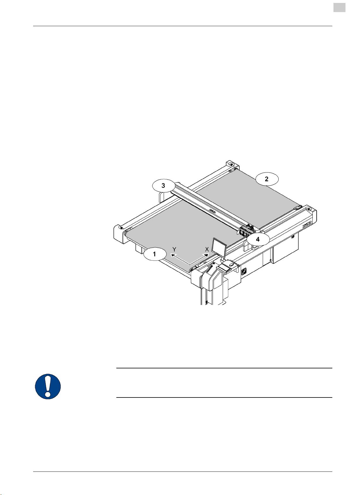
Directional information
Directions such as "right, left" or "forwards, backwards" are specified according to the
operator's view of the machine during operation.
2
000003,07,05-2010, jmu
Fig. 2-1 Directional information
1 Front 3 Left
2 Back 4 Right
Y Y axis X X axis
Important information
Important!
Refers to user tips and useful information which enhance the usability and prolong
the service life of the machine and make the work significantly easier.
2-1
Page 18

2
Product description G3 series
Product identification
2.2 Product identification
2.2.1 Rating plate
Important!
The rating plate is used to uniquely identify your machine.
Fig. 2-2 Position of rating plate
1 Manufacturer
2 Product category
3 Device type
4 Serial number
1
see chapter "Introduction", "Standardisation, CE marking"
Structure of the serial number
Example:
Serial number Description
G3 Product
00L Bar length
25 Table length
0001 Consecutive device number
5 Year of manufacture
6 CE marking
7 Manufacturer's address
1
2-2
000003,07,05-2010, jmu
Page 19

G3 series Product description
Intended use
2.2.2 UL marking
2
Fig. 2-3 UL marking
1 UL marking (Canada, USA)
2 Voltage range
2.3 Intended use
The cutter system can be used for the following purposes:
– As an output device for CAD/CAM data
– For processing and labelling materials arranged on the table
Aside from this, the intended use and the limits of the application are as follows:
– Depending on the tools and material feed system available,
– Described in the chapters "Tools", "Modules" and "Material transport".
3 Max. current
4 Frequency
000003,07,05-2010, jmu
2-3
Page 20
2
Product description G3 series
Cutter - overview
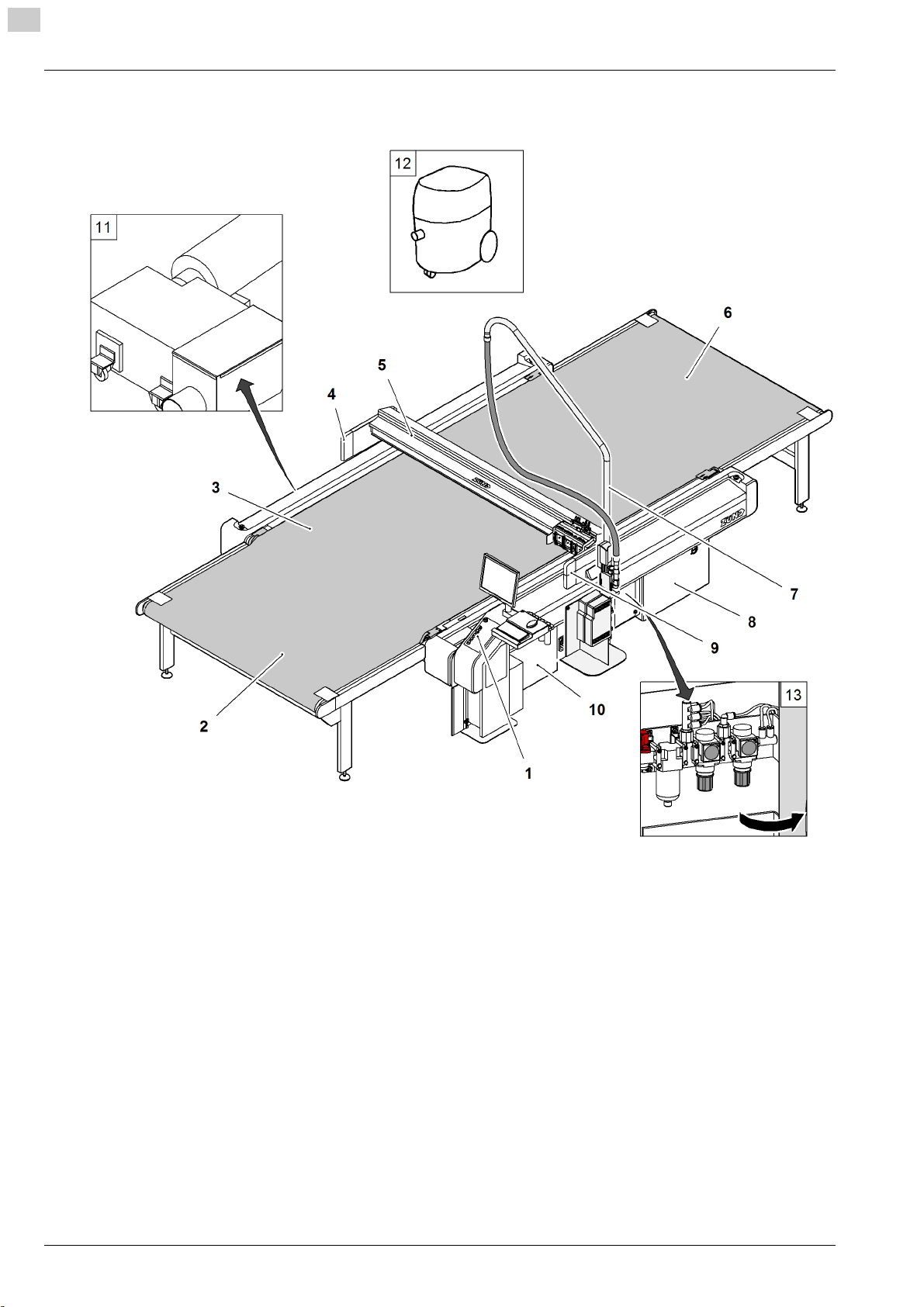
2.4 Cutter - overview
2-4
Fig. 2-4 Cutter - overview
1 Work station
2 Cutter extension, front
3 Table with vacuum
4 Left-hand safety device
5 Bar
6 Cutter extension, rear
7 Boom for router option
8 Power unit
9 Right-hand safety device
10 Electronics unit
11 Vacuum generator
12 Extractor (optional)
13 Maintenance unit (air pressure setting)
000003,07,05-2010, jmu
Page 21

G3 series Product description
Modules, tools
2.5 Modules, tools
2.5.1 General
Modules
The use of modules and tool inserts means that Zünd
cutters can be highly specialised on the one hand,
whilst still being able to be easily converted for
processing other materials on the other hand.
As standard three modules can be fastened onto the
module carriage.
Instructions on the operation of your module can be
found in the chapter "Modules"/"Tool inserts".
Tools
Zünd offers tools for processing the most wide ranging
materials. A selection of important tool inserts can be
found under the corresponding module.
On the Zünd homepage (www.zund.com) you can find
Fig. 2-5 Modules - tool inserts - tools
1 1 Modules (UM/RM/PUM)
2 2 Tools (EOT/POT/DRT)
3 3 Module carriage
4 4 Router, blade, etc.
all the current tool inserts or contact your Zünd partner
for detailed information.
Instructions on the operation of your tool/module can
be found in the chapter "Modules"/"Tools".
2
2.5.2 UM
Tangentially controlled high-performance module for
the following tool inserts:
•POT
•EOT
• DRT
• Various insert sleeves and tool holders
000003,07,05-2010, jmu
2-5
Page 22

2
Product description G3 series
Modules, tools
2.5.2.1 Tools for the UM
POT: Pneumatic oscillating tool for thick or tough
materials such as foam, filling materials, thick leather,
upholstery fabrics etc.
EOT: Electrical oscillating tool for cutting soft to
average toughness materials.
DRT: Driven tool for rotating knives for cutting textiles,
fibrous materials such as Kevlar, carbon
VCT: Cutting tool for producing V-cuts
UCT: Cutting tool which can be used universally
KCT: Cutting tool for foils with and without mount
material
UDT: Drawing tool
PPT: Passepartout (all-purpose) tool
2-6
000003,07,05-2010, jmu
Page 23

G3 series Product description
Modules, tools
2.5.3 RM-A
Router module for the use of 1000 W Zünd motor
spindles.
2
2.5.4 PUM
Motor spindle with 1000 W for the processing of the
most wide-ranging materials.
Punching and stamping module for the processing of
leather materials.
000003,07,05-2010, jmu
2-7
Page 24

2
Product description G3 series
Modules, tools
2.5.5 MAM-S/D
Single/double marking module for use of ballpoint pens
and other marking inserts.
2-8
000003,07,05-2010, jmu
Page 25

G3 series Product description
Material handling, options
2.6 Material handling, options
2.6.1 Laser pointer
The laser pointer is used as an aid for the precise
definition of the reference point
2.6.2 ICC camera
2
The ICC camera is used as an aid for importing the
registration marks. The processing of the data is
dependent on the communication software.
2.6.3 Cutter with static work surface
The feeding and removal of the processing material
takes place on the work surface of the cutter. The work
surface is protected against damage using a cutting
base.
Fig. 2-6 Static work surface
000003,07,05-2010, jmu
2-9
Page 26

2
Product description G3 series
Material handling, options
2.6.4 Cutter with conveyor
Conveyor systems are used for pulling the materials to
be worked with. The conveyor belt is used as a cutting
base and conveyor belt at the same time.
During the processing, the material to be processed is
fixed in place using a vacuum. After cutting, the bar
moves backwards. The conveyor clamping elements
fix the conveyor belt and the feeding clamps are
pressed onto the material to be pushed forward. The
bar tightens the conveyor belt to the set position.
The shape of the feeding clamps varies depending on
the material to be worked with. An auxiliary drive is
used in the case of larger tables or processing
Fig. 2-7 Conveyor
materials that are heavier for transportation.
Cutter extensions guarantee efficient work. The
material supply/removal is carried out while the cutter
is completing its jobs. These extensions are available
in different sizes, either with or without auxiliary drive.
Fig. 2-8 Cutter extension
2.6.5 Sheet feeder options
Fully-automatic sheet feeding
2-10
000003,07,05-2010, jmu
Page 27

G3 series Product description
Material handling, options
2.6.6 Drip tray
Catches cutting waste
2
000003,07,05-2010, jmu
2-11
Page 28
2
Product description G3 series
Technical description
2.7 Technical description
2.7.1 Complete machine
The G3 cutter is a variable processing system for flexible and rigid materials with
various tool systems. Extension options are available to provide improved handling
and for the adjustment of the system to special requirements or for processing
specific materials.
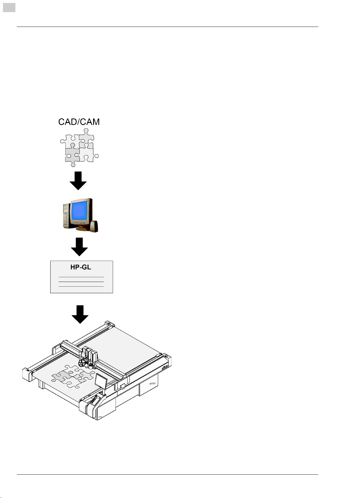
2.7.2 Schedule of work sequences
Starting point: CAD/CAM data
Communication software (e.g. ZCC)
Sending the HP-GL data to the cutter
Processing the sent data
2-12
000003,07,05-2010, jmu
Page 29

G3 series Product description
Technical description
2.7.3 Complete machine
Table/vacuum plate
The work surface is designed as a perforated sheet. Vacuum zones are arranged
under this perforated sheet which are connected to a high-performance vacuum
generator via a distributor.
The vacuum is used for holding down and tightening the material to be processed.
The cutter control permits sequential activation/deactivation of the individual vacuum
zones and therefore reduces energy consumption. The vacuum generator (turbine
vacuum generator, vacuum pump) automatically regulates the vacuum strength (100
mBar).
Electronics unit
The electronics unit is housed in the front right-hand side of the cutter and is only
accessible for service personnel via a removable cover. The cutter control is housed
in the electronics unit.
Power unit
The power unit is housed in the rear right-hand side of the cutter and is only
accessible for service personnel via a removable cover. The power unit contains the
power supply of the complete cutter and is activated/deactivated using an on/off
switch. The connection of the individual consumers takes place using software
control if required.
2
Pneumatics
Air pressure and air flow are adjusted for the respective consumer via a maintenance
unit. The maintenance unit is accessible via a service door so that settings and
maintenance work can be carried out.
000003,07,05-2010, jmu
2-13
Page 30

2
Product description G3 series
Technical description
2.7.4 Movement system
The G3 series has four electronically driven axes.
Axis Function Movement system
Bar Drive via toothed belt/steel belt
X
Material transport, material
transport extension
Y Movement of the module
carriage
Z Height adjustment of the
module
T Rotary movement of the
module
X axis - bar
The bar is driven by a motor via a toothed belt/gear mechanism and a toothed belt/
metal belt combination. The construction ensures that the function is backlash-free
and it also minimises wear on the drive system. The bar is supplied with control
signals and compressed air via an energy chain. All drive parts are protected against
direct access/contamination using covers.
Feed clamp elements, feeding
clamps, auxiliary drive
Drive via toothed belt/steel belt
Example: Universal module,
routing module
Example: Universal module
X axis - material transport
The material transport takes place via conveyor clamp elements and feed elements
on the bar, which move the conveyor belt including the material to be used via the
bar movement. In the case of large cutters, or cutters with material transport
extension, an auxiliary drive is also used.
Y axis - module carriage
The module carriage is driven by a motor via a toothed belt/gear mechanism and a
metal belt. The construction ensures that the function is backlash-free and it also
minimises wear on the drive system. The module carriage is supplied with control
signals and compressed air via an energy chain. All drive parts are protected against
direct access/contamination using covers.
Z axis - height adjustment of the module
Machine-controlled setting of the processing height (e.g. universal module)
T axis - rotary movement of the module
Modules with integrated T axis (e.g. universal module)
2-14
000003,07,05-2010, jmu
Page 31

G3 series Product description
Technical description
2.7.5 Processing materials
The multitude of materials which can be processed with the different module and tool
systems means that there is no single way to achieve the target.
However, the following factors always play an important role and must always be set/
selected for the specific material:
• Selection of the module and the tool insert
• Selection of the knife/router
• Descending speed, descending acceleration
• Cutting speed, acceleration
Contact your Zünd partner or the Zünd customer information centre for more precise
information.
2
000003,07,05-2010, jmu
2-15
Page 32

2
Product description G3 series
Technical information
2.8 Technical information
2.8.1 Dimensions and weights
2.8.1.1 Basic device
Type Work surface
(D x E) [mm]
M-1600
M-2500
L-2500
L-3200
XL-1600
XL-3200
2XL-1600
2XL-3200
3XL-1600
3XL-3200
1330 x 1600
1330 x 2500
1800 x 2500
1800 x 3200
2270 x 1600
2270 x 3200
2740 x 1600
2740 x 3200
3210 x 1600
3210 x 3200
Fig. 2-9 Basic device dimensions
1
Overall dimensions
(B x C) [mm]
2055 x 2512
2055 x 3412
2525 x 3412
2525 x 4112
2995 x 2512
2995 x 4112
3465 x 2512
3465 x 4112
3935 x 2512
3935 x 4112
Width B1
[mm]
300 624 830
Width B2
[mm]
Work surface
Height
(A) [mm]
2-16
000003,07,05-2010, jmu
Page 33

G3 series Product description
Technical information
2
Typ e Static material clea-
rance width
M-1600
M-2500
L-2500
L-3200
XL-1600
XL-3200
2XL-1600
2XL-3200
3XL-1600
3XL-3200
1
The work surface and material clearance width are dependent on the tool and the
1610
1610
2080
2080
2550
2550
3020
3020
3490
3490
1
(D) [mm]
Material clearance
width with CV (D)
[mm]
1330
1330
1800
1800
2270
2270
2740
2740
3210
3210
Material clea-
rance thickness
2
[mm]
61/31
module
2
Two versions are available
max.
Typ e Weight [kg]
floor load
[kg/m
2
]
M-1600
M-2500
L-2500
L-3200
XL-1600
XL-3200
2XL-1600
2XL-3200
3XL-1600
3XL-3200
670
840
970
1120
890
1290
980
1420
1120
1610
Typ e Max. weight proces-
sing material [kg]
M-1600
M-2500
L-2500
L-3200
XL-1600
XL-3200
2XL-1600
2XL-3200
3XL-1600
3XL-3200
-
340
450
580
370
740
440
880
520
1040
200
Max. weight processing material [kg/m
55
2
]
000003,07,05-2010, jmu
2-17
Page 34

2
Product description G3 series
Technical information
2.8.1.2 Cutter extension
Important!
Cutter extensions do not increase the work surface of the cutter. They serve as a
transport belt extension for the feeding and removal of material
Fig. 2-10 Cutter extension dimensions
Cutter extension T1
Type
CE0800 745
CE1250 1195
CE1600 1545
CE2500 2445
CE3200 3145
[mm]
M-1600
M-2500
L-2500
L-3200
XL-1600
XL-3200
2XL-1600
2XL-3200
3XL-1600
3XL-3200
2-18
000003,07,05-2010, jmu
Page 35

G3 series Product description
Technical information
2.8.2 Electrical connection, power consumption
Electrical connection 400 V, 50/60 Hz
Value Units
2
Voltage 3-phase, 400
V
L1, L2, L3, N, PE
Mains frequency 50/60 Hz
Power consumption - 3 phases(without
3.6 KW
vacuum generator)
Current consumption, 3 phases(without
max. 12 A
vacuum generator)
Mains fuse, min.
1)
only applies for the basic device, the minimum requirement for the mains fuse
1
16 A
increases depending on the vacuum generator
Vacuum generator
For additional data see rating plate/original operating manual in chapter "Additional
specifications"
The vacuum generator is selected according to the following criteria:
– Cutter model
– Desired application
– Local mains voltage and frequency
Vacuum generator 1 - 9 KW Value Units
Voltage 3-phase, 400 V
Mains frequency 50/60 Hz
Power consumption - 3 phases 1 - 9 KW
Mains fuse, min.
1
32 A
Vacuum generator 1 - 15 KW Value Units
Voltage 3-phase, 400 V
Mains frequency 50/60 Hz
Power consumption - 3 phases 1 - 15 KW
Mains fuse, min.
1
2.8.3 Environmental conditions
Operating temperature + 10 to + 35 °C
Storage temperature - 20 to + 55 °C
Relative humidity 10 - 80, non-
2.8.4 Basic device compressed air
Conveyor feeding clamps Value Units
Operating pressure 0.6 - 0.8 MPa
Min. air flow 20 l/min
32 A
Value Unit
%
condensing
000003,07,05-2010, jmu
2-19
Page 36

2
Product description G3 series
Technical information
Conveyor feeding clamps Value Units
Setting - pressure regulator maintenance unit
(P3)
Control of vacuum zones, supply of various
modules, tools
Operating pressure 0.6 - 0.8 MPa
Min. air flow 20 l/min
Setting - pressure regulator maintenance unit
(P2)
Additional specifications and requirements can be found in the chapters "Modules,
tools, options, material handling"
2.8.5 Control unit
Execution
4-axis control (X, Y, T, Z)
Variable, prognostic vector processing.
Software
Command set HP-GL, extended
Data format ASCII
0.6 MPa
Value Units
0.6 MPa
Interface
RS-232C / V24 600 - 38200 Baud
1 MB input buffer with replot function
2-20
000003,07,05-2010, jmu
Page 37

G3 series Product description
Technical information
2.8.6 Performance
Precision
Value Units
Resolution of measuring system 0.005 mm
Positioning accuracy at a constant temperature ± 0.1 mm
Repeat accuracy ± 0.03 mm
Evenness of the table ± 0.2 mm
Cutting performance
Value Units
Speed in the vector direction 1 - 1414 mm/s
Max acceleration in the vector direction
1
Max. permitted printing force of the printhead
(creasing)
1
depending on the module equipment and cutter size
9.1 m/s
200 N
2
2
000003,07,05-2010, jmu
2-21
Page 38

2
Product description G3 series
Technical information
2.8.7 Emissions
Noise
Continuous sound pressure level of the cutter < 75 dB (A)
Depending on the tool system and materials to be processed:
– if the limit value of 85 dB (A) is exceeded,
– noise protection measures may be necessary
Important!
Protective measures against noise and emissions (dust, solvents, material residues
etc.) for each tool system are specified in chapter 3.
Electromagnetic emissions
The G3 series meets requirements of the following technical standards:
• EN 61000-6-2 EMC, interference resistance in industrial environments
• EN 61000-6-4 EMC, emission standard in industrial environments
Please ask the manufacturer if you wish to refer to the test reports.
2.8.8 FCC approval
NOTE:
This equipment has been tested and found to comply with the limits for a Class A
digital device, pursuant to part 15 of the FCC Rules. These limits are designed to
provide reasonable protection against harmful interference when the equipment is
operated in a commercial environment. This equipment generates, uses, and can
radiate radio frequency energy and, if not installed and used in accordance with the
instruction manual, may cause harmful interference to radio communications.
Operation of this equipment in a residential area is likely to cause harmful
interference in which case the user will be required to correct the interference at his
own expense.
NOTE:
Changes or modifications made by the user that are not expressly approved by the
party responsible for compliance could void the user's authority to operate the
equipment.
2-22
000003,07,05-2010, jmu
Page 39

G3 series Safety
General
3 Safety
3.1 General
Your safety – as the operator, service engineer or otherwise – is the primary concern.
Certain situations, problems or faults that may occur on the equipment could put your
safety at risk if you are not aware of the steps you should take to avoid the resulting
dangers.
Contents
– Stipulation of the correct use of the machine
– Generally applicable safety instructions and safety regulations to be observed
– Explanation of the meaning of symbols and pictograms which are used in this
manual and in signs on the machine
– Location of safety and monitoring devices on the machine
– Information on protective equipment required and of requirements for operators
and maintenance personnel
Specific activity-related and situation-related safety instructions are given in the
corresponding procedures in the following chapters of this manual and in other parts
of the documentation.
3
Latest technology
The supplied machine meets the standards of the latest technology at the time of
delivery.
However, the equipment may pose dangers unless the safety instructions in this
guide are observed and implemented.
000011,08,11-2009, jmu
3-1
Page 40

3
Safety G3 series
Proper use
3.2 Proper use
The proper use of the machine is essential for its safe operation.
The equipment supplied:
• Is listed and labelled
• Determines the possible uses of the machine
The machine is intended for use as an output device for CAD/CAM data for the
labelling and processing of materials arranged on the table.
The intended use and the limits of the application are dependent on:
• The module and tool system that is used
• The existing material transport system
Any other use or any use going beyond this scope constitutes improper use. The
user bears sole liability for any damage arising as a result of improper use.
The operation of the machine is also seen as correct if:
• All nationally imposed safety regulations are complied with
• The safety instructions in this operating manual are observed
• The operating conditions are adhered to and the prescribed materials are used
3.3 Examples of improper use
Improper use of the machine can:
• Cause injury
• Result in serious damage to the machine
• Lead to loss of warranty
Improper use of the machine includes, among other things:
• Any structural modification to the machine carried out without written agreement
from the manufacturer
• Use of unsuitable modules/tool inserts
• Servicing work performed by untrained or unauthorised personnel
• Installation of spare parts and use of accessories and resources not approved by
the manufacturer
• Deliberate or careless interference with the machine during operation
• Commissioning of the machine
– Without sufficient personal protection equipment
– Without the designated protective and safety measures
– If the operating manual is incomplete or not available in the local language
• Non-adherence to maintenance requirements
• Failure to react to signs of wear and damage
3-2
000011,08,11-2009, jmu
Page 41

G3 series Safety
Hazard warnings, important instructions
3.4 Hazard warnings, important instructions
3.4.1 Explanation of the hazard warning
Both in the operating manual and on the device itself, dangers, important instructions
and user tips are designated by special symbols and signal words as follows.
Danger!
The safety instruction Danger
• Refers to an immediate threat
• Refers to operational and service risks
• Warns of serious effects on health and safety, including life-threatening injuries.
Warning!
The safety instruction Warning
• Refers to a dangerous situation
• Refers to operational and service risks
• Warns of serious effects on health and safety, including life-threatening injuries.
3
Attention!
The safety instruction Caution
• Refers to a dangerous situation
• Refers to operational and service risks
• Warns of minor injuries and other serious damage to the machine and secondary
damage
Attention!
The safety instruction Caution without a hazard symbol
• Refers to a dangerous situation
• Refers to operational and service risks
• Warns of serious damage to the equipment, damage to other property and consequential damage
Important!
Refers to user tips and useful information which enhance the usability and prolong
the service life of the machine and make the work significantly easier.
000011,08,11-2009, jmu
3-3
Page 42

3
Safety G3 series
Hazard warnings, important instructions
3.4.2 Structure of the hazard warnings
Example:
Warning!
Risk of poisoning from the emission of toxic dust
Processing certain materials can lead to the creation of toxic dust with significant risk
to health.
• Obtain information about the toxicity of the material to be processed from the manufacturer
• Use a suitable extraction unit or take other appropriate action accordingly
Hazard warnings consist of the following units:
1 The hazard symbol of the appropriate signal colour
2 The signal word corresponding to the danger resulting from the situation
3 The description of the danger
4 The description of the consequences which could result from this hazardous si-
tuation
5 Possible actions and codes of conduct to prevent the hazard occu r r i n g o r t o av e r t
possible hazardous situations
3-4
000011,08,11-2009, jmu
Page 43

G3 series Safety
Areas of responsibility
3.5 Areas of responsibility
The manufacturer
• Is responsible for the safe condition of the machine on delivery, including instruction handbook and accessories, according to the sales documentation.
The owner or person authorised by him:
• Ensures that only adequately trained personnel, who have been properly instructed and have read and understood the content of the safety instructions in
this chapter, will operate and maintain this machine
• Clearly determines the responsibility of the operators and service personnel as
required in the instruction handbook
• Checks the personal protective equipment of operators and service personnel
• Is responsible for the safe condition of the machine
• Ensures that servicing and maintenance is carried out according to the maintenance schedule
• Notifies the manufacturer of any accident involving the machine that results in serious injury or substantial material damage
• Removes the machine from service immediately if defects arise that are detrimental to its operational safety
3
Operators and service personnel:
• Wear the necessary personal protective gear
• Halt operation immediately in the event of faults
• Report any changes which are detrimental to operational safety
• Keep the equipment clean
• Check the operation of the emergency stop switches before starting work
3.6 Personnel requirements
The operators and service personnel must meet the following requirements:
• Be physically and mentally suitable
• Be qualified by means of thorough training in the use of the machine
• Have read and understood the operating manual/service manual
• Be over the age of 16
• Have knowledge of first aid and the use of fire extinguishers
000011,08,11-2009, jmu
3-5
Page 44

3
Safety G3 series
Rules and safety at work
3.7 Rules and safety at work
• The operation of the machine is always subject to local regulations regarding safety at work and accident prevention.
• Before the machine is put into operation: Always check the safety equipment and
protective covers.
• If a hazardous situation occurs, switch the machine from the ONLINE operating
status to the STOPPED/OFFLINE operating status:
– Switching can be carried out by pressing the ONLINE button on the operating
unit
– By pressing one or more direction keys (emergency stop function).
• You are not permitted to make unauthorised modifications and changes to the
machine which might affect the system's safety. Accessories or spare parts produced by other manufacturers may only be used with the machine with the written approval of the manufacturer.
• Only service personnel authorised by the manufacturer are permitted to install,
commission, maintain and repair the machine.
• Before carrying out any maintenance, repair and modification work:
– Switch the machine off using the on/off switch and secure with a lock
– Prevent the machine being switched on inadvertently by removing the mains
supply cables to the distribution box (several mains connections).
3.8 Procedure in case of malfunctions
In principle, any troubleshooting work or inspection on the cutter is to be carried out
only when it is switched off.
The following must never be by-passed or rendered ineffective:
• Light barriers and protective trip switches on the bar
• Monitoring sensors
• Safety and control switches in the machine
If malfunctions cannot be remedied by the operators using simple measures, then
the responsible service station must be informed.
3-6
000011,08,11-2009, jmu
Page 45

G3 series Safety
Danger areas
3.9 Danger areas
3.9.1 General danger area
3
Fig. 3-1 General danger area
1 Danger area
000011,08,11-2009, jmu
3-7
Page 46

3
Safety G3 series
Danger areas
3.9.2 Danger area on the module carriage
Attention!
Risk of injury on the module carriage
The danger area on the module carriage is not secured using safety devices.
• Do not reach into the danger area during the manual initialisation
• Secure the danger area on the module carriage using the slot protective plates
Fig. 3-2 Danger area on the module carriage
1 Danger area
2 Slot protective plate
Place a slot protective plate on each module slot on which no module is installed.
3-8
000011,08,11-2009, jmu
Page 47

G3 series Safety
Danger areas
3.9.3 Danger area during the installation
Attention!
Risk of injury during the manual initialisation of the tool.
The safety devices are not active during the manual initialisation
• Do not reach into the danger area during the manual initialisation
• Use the automatic initialisation function for the initialisation
3
Fig. 3-3 Danger area during the installation
1 Danger area
2 Tool (e.g. EOT)
Safety distance during the manual initialisation
The safety distance (b) for operating personnel during manual initialisation is 25 cm.
Do not reach into the danger area during the initialisation phase.
3 Example: Module 2
b Safety distance
000011,08,11-2009, jmu
3-9
Page 48

3
Safety G3 series
Working and traffic area
3.10 Working and traffic area
Warning!
There is a danger of injury to others through inappropriate behaviour or
carelessness.
Please advise others to maintain an appropriate safety distance from the designated
work and traffic zone.
Fig. 3-4 Working area around the cutter
A Working area - active area of the tool
B Working and traffic area of the operator
C Minimum safety distance for other personnel
Safety distance for other personnel
The safety distance for other personnel extends over the surface of the cutter plus a
distance of at least one metre.
Working and traffic area
The working and traffic area extends over the surface of the cutter with fittings and
options plus a distance of at least one metre.
Use with conveyor extension
When using a cutter extension, the loading and removal of material is permitted
outside of the danger zone (working and active area).
3-10
000011,08,11-2009, jmu
Page 49

G3 series Safety
Safety signs
3.11 Safety signs
3.11.1 Responsibility of the operator
Warning!
Risk of injury due to a lack of safety signs
Risks and sources of danger cannot be localised due to the lack of safety signs.
• Replace missing or illegible safety signs as per Fig. 3-1
The operator is responsible for replacing missing/illegible safety signs on the
machine. The appropriate safety signs can be requested from your service partner.
3.11.2 Position of the safety signs
3
000011,08,11-2009, jmu
Fig. 3-5 Safety signs
1 Danger of hand injuries
2 Danger of electrical safety hazard
3 Laser beam warning
Important safety signs on the machine must be followed. Otherwise, this could result
in serious injuries or death. Special module or tool specific signs can be found in the
relevant operating manual.
4 Warning of the danger of cuts
5 Wear eye protection
6 Wear protective gloves
3-11
Page 50

3
Safety G3 series
Safety signs
Warning!
Safety risks due to missing or illegible safety signs.
Check all safety signs on a regular basis for legibility and completeness.
Replace missing or illegible safety signs promptly with new original signs.
Meaning of safety signs
The symbols on the safety signs
– have specific meanings
– are located wherever certain behaviour is prohibited due to it being potentially
dangerous
Prohibition signs
– are round and red-coloured
– are located wherever certain behaviour is prohibited due to it being potentially
dangerous
Order signs
– are blue and circular
– Stipulate the wearing of personal protective equipment to protect against ha-
zards
Wear eye protection
Wear protective gloves
Fire protection signs
– are rectangular and red-coloured
– Are intended to draw attention to equipment and information for use in the event
of a fire
3-12
000011,08,11-2009, jmu
Page 51

G3 series Safety
Safety signs
Warning signs
– are triangular and yellow-coloured
– Are intended to draw attention to objects and circumstances which represent a
potential danger to life and limb.
Danger of hand injuries (crushing)
Danger of hand injuries (severing)
Danger of electrical safety hazard
3
Laser beam warning
000011,08,11-2009, jmu
3-13
Page 52

3
Safety G3 series
Safety and monitoring devices
3.12 Safety and monitoring devices
Fig. 3-6 Safety and monitoring devices
1 Emergency stop switch
2 Protective system
3 Operating unit
3-14
000011,08,11-2009, jmu
Page 53

G3 series Safety
Safety and monitoring devices
3.12.1 Protective system
Attention!
If there is a collision, the bar may cause serious injuries.
The high level of kinetic energy of the drive results in a braking distance which cannot
be ignored.
Light barriers and safety cut-offs are no guarantee against injuries.
The protective system is made up of protective trip switches and light barriers on the
ends of the bar.
Protective trip switches and light barriers are part of a self-monitoring safety
shutdown system.
If protective trip switches or light barriers cause an obstruction then the following
protective measures are introduced:
– An emergency stop halts all movements
– The operating status STOPPED is activated
– An error message is displayed
3
Protective trip switches
Protective trip switches trigger the safety shut-down if they are touched by an
obstruction. They are used as hand protection.
Light barriers
The working area is monitored by light barriers on the front and rear side of the beam.
Important!
The light barriers are active in all operating states.
3.12.2 Operating unit
Malfunctions are indicated on the LCD display.
An acoustic signal is emitted in the case of emergency stop and to acknowledge
keypad entries.
000011,08,11-2009, jmu
3-15
Page 54

3
Safety G3 series
Safety and monitoring devices
3.12.3 Emergency stop switch
– Emergency stop switches are part of a protective circuit
– They allow the machine to be turned off quickly in hazardous situations
Two emergency stop switches can optionally be fitted on the edges of the machine.
The mains power supply to the whole machine is switched off as soon as the
emergency stop switch is pressed. The operating unit remains switched on.
Attention!
Pressing the emergency stop switch can damage the cutter.
Do not press the emergency stop switch to switch off the machine in routine
operation.
Important!
To unlock an activated emergency stop switch after regaining operational safety, turn
the switch anticlockwise (see chapter "Controls and operation").
3.12.4 Safety cut-off feature
The following safety measures are introduced when an overload occurs or an axle
drive (T, X, Y, Z) is blocked:
– An emergency stop is carried out
– The cutter switches to the operating status STOPPED
– An error message and an alert buzzer indicate the safety cut-off
3-16
000011,08,11-2009, jmu
Page 55

G3 series Safety
Personal protective equipment, clothing
3.13 Personal protective equipment, clothing
The safety equipment required for operating the machine is dependent on the
following factors:
– The module and tool system
– The material to be processed
When operating the machine or carrying out maintenance or servicing work, wear
close-fitting clothing and the appropriate personal protective equipment.
Warning!
Risk of injury from being caught or trapped in moving machine parts.
• Do not wear loose clothing, scarves, open jackets or open shirt sleeves.
• Remove all jewellery before starting maintenance and servicing work.
Personal protective equipment comprises:
• Work clothes (service personnel),
• Protective goggles (operators, service personnel):
– To provide protection from particles during cutting operations
– To protect the eyes from dangerous radiation
– To protect the eyes from chemicals
• Protective gloves where injury is possible due to:
– Burns
– Sharp or pointed objects
• Chemical-resistant protective gloves where injury is possible due to:
– Chemicals (cleaning agents)
• Breathing protection when working with poisonous substances
• Ear protection if the continuous sound pressure level is over 80 dB.
3
Important!
You are personally responsible for:
• Using the required personal protective equipment
• Cleaning and maintaining the equipment on a regular basis
• Replacing damaged and unusable elements of protective equipment in a timely
fashion
000011,08,11-2009, jmu
3-17
Page 56

3
Safety G3 series
Mechanical hazards
3.14 Mechanical hazards
3.14.1 Gathering, retraction
Hazards caused by the bar, modules or the tool system during gathering and
retraction
Possible consequences:
• Cuts, bruising and crushing of fingers and hands
• Bruising of head and arms
• Tearing out of hair
• Damage to clothing
• Damage to the machine
Precautions during the initialisation and the operation in the ONLINE operating
status:
• Do not touch tool head and bar
• Do not enter the working/active area
• Do not touch table surface and material to be processed
• Do not lay your hands on side covers
• Do not lean over the working surface
• Avoid leaving long hair loose and wearing loose clothes and ties
These precautions specifically apply if the cutter can be switched into ONLINE
operating status by the CAD/CAM system.
3.14.2 Gathering, impacts of foreign objects
Foreign objects on the table are grasped and pushed away by the bar and the tool
head.
Possible consequences:
• Facial injuries and other injuries due to objects being pushed away
• Damage to the machine
Precautions during the initialisation and the operation in the ONLINE/OFFLINE
operating status:
• Do not place materials, tools or other objects on the table or side covers
• Before operation, check whether there are any objects on the table or the side
covers
3-18
000011,08,11-2009, jmu
Page 57

G3 series Safety
Risk of burns
3.14.3 Cuts and stab wounds
Knives, routers and punching inserts have very sharp edges which are sometimes
hidden by moving equipment (slipper spring).
Possible consequences:
• Cuts and stab wounds to the hands and arms
Precautions during the knife change, initialisation and the operation in the ONLINE
operating status of the machine:
• Be extremely careful when changing the tool inserts
• Do not enter the working area during the initialisation and during operation in the
ONLINE operating status
3.15 Risk of burns
Certain materials (metals) and tools (router) reach very high temperatures during
processing.
3
Possible consequences:
• Burns on the limbs
Precautions:
• Allow workpieces to cool before removing them
• Wear suitable protective gloves when removing workpieces that have just been
processed
• Allow tools (router, knife) to cool before removing them
000011,08,11-2009, jmu
3-19
Page 58

3
Safety G3 series
Electrical hazard
3.16 Electrical hazard
Warning!
Risk of death or injury from electric shock.
The machine is operated with a mains voltage of 380 V, system frequency of 50/60
Hz.
Safety instructions
• Only trained service personnel are authorised to open switch boxes and electronics units.
• Ensure that mains cables are protected against mechanical loading and are laid
so that they are free from strain.
• Replace damaged cables immediately.
3-20
000011,08,11-2009, jmu
Page 59

G3 series Safety
Risks arising from the emission of toxic dust
3.17 Risks arising from the emission of toxic dust
Warning!
Risk of poisoning from the emission of toxic dust
Processing the most wide-ranging materials can lead to the creation of toxic dust with
significant risk to health.
• Obtain information about the toxicity of the material to be processed from the manufacturer.
• Use a suitable extraction unit or take other appropriate action accordingly.
The company operating the system is responsible for making sure that all national
regulations concerning the maximum permissible dust concentration at work are
adhered to. When handling hazardous types of dust, all local safety regulations as
well as the manufacturer's instructions must be observed. Use special vacuum
cleaners with specially adjusted dust filters if you are routing/processing hazardous
materials. Zünd offers suction systems which meet the following regulations as
accessories:
– The extraction of hazardous dusts with a maximum concentration at work of up
to 0.1 mg/m
– The extraction of dusts conforming to dust class H
3
and the extraction of wood dusts of dust class M
3
3.18 Risks arising from the processing of toxic/hazardous materials
Warning!
Risk of poisoning from emissions when processing toxic materials
Processing the most wide-ranging materials can lead to toxic emissions (gases, dust
etc.) with significant risk to health.
• Never process toxic/hazardous materials!
• Obtain information from the manufacturer of the material to be processed about
its toxicity.
Guidelines
• The company operating the system is responsible for establishing which processing materials are toxic/hazardous.
• It is prohibited to process toxic materials on Zünd cutters without appropriate additional safety measures!
• The company operating the system is responsible for installing appropriate additional safety measures!
000011,08,11-2009, jmu
3-21
Page 60

3
Safety G3 series
Environmental hazard
3.19 Environmental hazard
Warning!
Processing residues, operating fluids etc. can cause damage and pollute the
environment if they enter the soil, watercourses or the sewage system.
Explanation of the hazard label
Hazard label for substances that are harmful to the environment
Safety regulations and protective measures
• Dispose of waste materials in accordance with current national environmental
protection regulations. In case of doubt, check the appropriate disposal methods
with your local collection point or recycling centre.
• Collect different chemicals in separate containers.
3-22
000011,08,11-2009, jmu
Page 61

G3 series Safety
Handling and storage of chemicals
3.20 Handling and storage of chemicals
Warning!
Cleaning agents, operating fluids etc., can cause skin irritation and can therefore be
hazardous to health if handled carelessly.
Always wear personal protective equipment when working with chemicals.
Explanation of the hazard label
Hazard label for toxic substances
Hazard label for harmful substances
3
Hazard label for irritating substances
Important!
Chemicals classed as irritants are used to operate and clean this machine (cleaning
agents, operating fluids). Safety datasheets of the substances in question can be
downloaded from the Zünd homepage (www.Zund.com).
Safe handling of chemicals
Disposal!
Dispose of chemicals in accordance with national regulations.
• Store chemicals in tightly closed containers in a cool dry place (between 5 °C and
30 °C).
• Protect the containers from heat and direct sunlight.
• Provide good ventilation, including at floor level.
• Store chemicals in accordance with local regulations.
• Keep containers tightly closed.
• Use chemicals only for the intended purpose.
000011,08,11-2009, jmu
3-23
Page 62

3
Safety G3 series
Risk of fire and explosion
3.21 Risk of fire and explosion
Warning!
There is a risk of fire when routing and cutting inflammable materials
Terminate the routing/cutting and leave the tool to cool in the case of
• Formation of smoke
• Discolourations on the router/knife which point to increased heat development
Warning!
Risk of dust explosions
Flying sparks or electrostatic charges result in the risk that there will be dust
explosions during the extraction of different materials.
• Obtain information about the risk of explosion when processing the type of material that you are using.
• If necessary, adjust the extraction to the required regulations.
Fire classes
Refer to the following table to find out which type of fire extinguisher is used for each
fire class:
A Solid materials, mainly organic in nature; e.g. wood, paper, textiles, etc.
B Liquid and liquefiable substances; e.g. petrol, oils, greases, paints, etc.
C Combustible gases: methane, propane, etc.
3-24
000011,08,11-2009, jmu
Page 63

G3 series Safety
Danger caused by laser beam (laser pointer)
In the event of a fire:
• Switch off the machine (emergency stop switch)
• Assess the situation: If the situation is dangerous, leave the area immediately
and call the fire brigade. Only try to extinguish the fire if your personal safety is
not at risk.
• Remove a suitable fire extinguisher (A, B, C) from its bracket and prepare it for
use.
• Locate the source of the fire. Attack the fire with repeated short bursts from the
extinguisher. Always spray the extinguishing agent into the source of the fire. In
other words, always aim at the burning material and not at the flames.
• After using the fire extinguisher, do not return it to its usual place but have it refilled immediately.
Observe the following safety rules and countermeasures
• Find out the number of locations where fire extinguishers are kept and familiarise
yourself with their use. The adjacent sign indicates the location of a fire extinguisher.
• Do not use inflammable cleaning agents to clean the machine.
• Store all processing materials in the proper manner in accordance with local guidelines.
3
3.22 Danger caused by laser beam (laser pointer)
Class 2 lasers are used as laser pointers. Momentary irradiation of the eyes, as can
occur if you accidentally look directly at the laser, is not dangerous. In addition,
depending on the construction, the laser beam is targeted directly at the material to
be processed.
Safety instructions
• Avoid direct, prolonged eye contact
3.23 Safety instructions for operators
This instruction manual cannot cover all possible situations and potential hazards.
It is therefore particularly important that operators
• have been thoroughly trained and are aware of and able to correctly assess the
hazards that can arise from the machine
• are familiar with all safety devices on the machine
• request information from the manufacturer without delay if an undocumented, hazardous situation arises in connection with the machine
In addition to these safety instructions, you must also observe the situation-related
safety notes in the chapters "Controls and operation" and "Maintenance and
cleaning".
000011,08,11-2009, jmu
3-25
Page 64

3
Safety G3 series
Safety precautions for service personnel
3.24 Safety precautions for service personnel
The reliability, readiness and service life of the machine greatly depend on you
carrying out your work in a conscientious manner.
Important!
Specialist knowledge and expertise are required to service and maintain the
machine. The manufacturer provides this knowledge through training courses which
are specially tailored for service personnel. Only personnel with Zünd certification are
permitted to carry out service work on Zünd cutters.
3.25 Disposal
Disposal!
Information about proper disposal
• Identifies toxic substances that are harmful to the environment
• Relates to the disposal of harmful substances
• Warns against disposal with domestic waste or environmental pollution caused
by hazardous substances and objects contaminated with such substances
Measures for disposal
Zünd cutters correspond with the requirements of the German Electrical and
Electronic Device Act and generally do not contain any poisonous substances or
consumables.
Contact Zünd customer services or your service partner before you dispose of your
cutter.
Dispose of cutting waste in accordance with current national environmental
protection regulations. In case of doubt, check the appropriate disposal methods with
your local collection point or recycling centre.
3-26
000011,08,11-2009, jmu
Page 65

G3 series Controls and operation
General
4 Controls and operation
4.1 General
This chapter familiarises you with the controls, guides you through the operational
procedures and describes the following operating steps:
– Daily commissioning
– Operation of the main components
– Detailed information on the operation of the machine
– Safe switching off of the machine
4.2 Safe working practices
Danger!
Operating errors or negligence can put human lives at risk as well as causing serious
damage to the machine.
The machine is fitted with safety devices to minimise risk. However, these safety
devices cannot guard against damage as a result of operating errors or negligent
working practices.
• Observe the safety requirements from the chapter "Safety" and the situational
safety requirements of the appropriate working step.
4
As the operator, you are responsible for the safe use of the machine.
You must observe the following:
– The safety instructions given in "Safety"
– The information contained in this chapter, bearing in mind the training provided
by the manufacturer or retailer
000010,10,05-2010, jmu
4-1
Page 66

4
Controls and operation G3 series
Controls
4.3 Controls
4.3.1 Control panel
Fig. 4-1 Control panel
1 Switch unit
2 Emergency stop switches
3 Operating unit
4-2
000010,10,05-2010, jmu
Page 67

G3 series Controls and operation
Controls
4.3.1.1 Operating unit
4
Fig. 4-2 Operating unit
1 Display
2 Soft keys
3 Navigation keys
4 Numerical keys
5
VAC
key (vacuum)
6 Coordinate system (axes)
7
STOP
key
ONLINE
8
9
SHIFT
10 Travel keys
11
Tool up/down
12 Function keys
key
key
key
000010,10,05-2010, jmu
4-3
Page 68

4
Controls and operation G3 series
Controls
4.3.1.2 Navigation keys
Fig. 4-3 Navigation keys
Key Function in the cutter menu
Use these keys to navigate through the menu
• If submenus are available, use this key to change to the next menu level
• Select setting/function
Change from a submenu or a setting to the previous
menu level
Key Function in the editor
Use these keys to move the cursor to the right or left
4.3.1.3 Numerical keys
Fig. 4-4 Numerical keys
Functions of the numerical keys
• Direct entry of the menu number
• Entry of values when there is a prompt
4.3.1.4 Function keys
4-4
Fig. 4-5 Function keys
Important functions are distributed to the function keys and therefore can be selected
directly. It is possible to programme the respective function of the function keys.
000010,10,05-2010, jmu
Page 69

G3 series Controls and operation
Controls
4.3.1.5 Travel keys
Fig. 4-6 Travel keys, shift key
4
1 Move module forwards
2 Move module to the left
3 Move module backwards
These keys are used to move the module unit in the operating statuses STOPPED
and OFFLINE.
If work is being carried out in the ONLINE operating status and a travel key is pressed
then the operating status changes to OFFLINE.
4.3.1.6 Soft keys
Fig. 4-7 Soft keys
These keys change their function depending on the situation. The currently valid
function is shown in the display.
4 Move module to the right
5 SHIFT key
000010,10,05-2010, jmu
4-5
Page 70

4
Controls and operation G3 series
Controls
4.3.1.7 Special keys, shortcuts
Important functions are defined with separate keys on the operating unit:
Current
operating status
STOPPED Switch off the machine Change to OFFLINE
ONLINE Switch off the machine
OFFLINE Switch off the machine
Current
operating status
Vacuum off Switch vacuum on
Vacuum on, suction
Vacuum on, blowing
Current
position
Up Z pos
Down Z pos Raise tool into upper position
Park position - Lower tool into upper position
With SHIFT key Without SHIFT key
With SHIFT key Without SHIFT key
Switch vacuum off
With SHIFT key Without SHIFT key
Lift tool into park position
Function
Change to STOPPED
Function
Vacuum menu
Function
Lower tool into lower position
Current
operating status
ONLINE
OFFLINE
STOPPED
Function
See section 4.6.3
4-6
000010,10,05-2010, jmu
Page 71

G3 series Controls and operation
Controls
4.3.2 Emergency stop switches
Attention!
Risk of damage to the machine.
Only use the emergency stop switches to switch off the machine in an emergency not for standard shutdown.
• Emergency stop switches are part of a protective circuit
• They allow the machine to be switched off quickly in a dangerous situation
4
000010,10,05-2010, jmu
Fig. 4-8 Emergency stop switches
The machine is fitted with four emergency stop switches as standard. They are
located as follows:
• 1 x on the operating console
• 3 x on the side support covers
Consequences of pressing an emergency stop switch:
• The drive motors are brought to a standstill and then are isolated from the energy
supply
• Safety-related units (modules, tools, auxiliary drive, sheet feeder, etc.) are isolated from the energy supply
• Units that are not safety-relevant or that are important for the operation of the device (vacuum, operating unit, dust extractor, compressor, etc.) remain switched
on
4-7
Page 72

4
Controls and operation G3 series
Controls
Important!
An emergency stop switch that has been pressed remains locked in the off position.
To unlock an activated emergency stop switch after regaining operational safety, turn
the switch anti-clockwise.
Procedure
⇨ When a hazard or a possibly hazardous situation occurs,
press an emergency stop switch without delay
✓ All machine movements are stopped. The emergency stop
switch that has been pressed remains locked in the off
position
⇨ Regain operational safety.
⇨ Turn the emergency stop switch clockwise until it is
unlocked
⇨ Use
Function test
F1
to reinitialise the machine
Danger!
Risk of injury due to defective emergency stop switches
Machines with defective emergency stop switches are not safe for operation. In
hazardous situations the machines cannot be stopped promptly.
• Check that the emergency stop switches are working on a daily basis.
• Do not start up a machine with defective emergency stop switches until the problem has been remedied by authorised personnel.
4-8
⇨ Press all emergency stop switches before the start of work/after the initialisation
of the device
✓ If the machine stops correctly then it is safe for operation
Problem solution
The machine does not stop correctly following the activation of an emergency stop
switch.
⇨ Do not start up the machine. Let authorised personnel remedy the problem.
000010,10,05-2010, jmu
Page 73

G3 series Controls and operation
Controls
4.3.3 Maintenance unit
The maintenance unit adjusts the air pressure to the switching of the vacuum
elements/various modules and options.
4
000010,10,05-2010, jmu
Fig. 4-9 Maintenance unit
1 Stopcock
2 Water separator
3 Air pressure setting for various
modules, vacuum elements (P2)
The maintenance unit is preset and adjusted.
Check the air pressure setting at regular intervals. The settings can be found in the
chapter "Product description", "Specifications".
4 Air pressure setting for conveyor clamp
elements and feed elements (P3)
5 Fixing bracket for an additional, optional
maintenance unit for various modules,
tool inserts and options
4-9
Page 74

4
Controls and operation G3 series
Controls
4.3.4 Interfaces
The machine has interfaces for data exchange. These are attached to the electronics
unit.
Fig. 4-10 Interfaces
1 LAN
2 Not used
3 USB (Host)
4 Status and error display
5 COM 1
6 COM 2
4-10
000010,10,05-2010, jmu
Page 75

G3 series Controls and operation
Menu navigation
4.4 Menu navigation
4.4.1 Menus and functions
Navigation
The cutter has a large number of functions. The current menu number and the
current menu are displayed in the header.
Fig. 4-11 Current menu number, menu
Graphic layout
Symbol Description
4
Menu
Blocked menu (user level)
Value/entry/command
Display of a value
Navigation in the menu
⇨ Use the navigation keys to scroll through the menu and use to
select a submenu/a function (e.g. Tools).
⇨ To return to the previous menu level press the navigation key . Press
to return back to the main menu.
Direct selection of menus
Each menu and each function is allocated a unique menu number. It is possible to
change between menus by entering the menu number. Two-figure menu numbers
(10, 11 etc.) are displayed in lower positions.
ESC
000010,10,05-2010, jmu
Commands/functions
Commands are carried out immediately after the entry.
⇨ Use the navigation keys to mark the required command and select
using .
⇨ The command can be triggered directly via the menu number. In order to do this,
enter the menu number on the control panel
An exception to this rule is made for safety-relevant commands (e.g. automatic
moving). These can be confirmed using OK or cancelled using ESC.
4-11
Page 76

4
Controls and operation G3 series
Menu navigation
Value/entry
⇨ If a flashing cursor appears on the display below a number, then a number input
is required
⇨ Enter the required value using the numerical keys
⇨ Check the value and confirm using OK or cancel the entry using ESC
Select
⇨ Use the navigation keys to select an entry from the list
⇨ Confirm using OK or cancel using ESC
Default settings (factory setting)
Default settings are available for many functions/values.
⇨ Select function
⇨Use Def to reset the value to the factory setting
Min/max settings (factory setting)
Limit values are available for many functions/values.
⇨ Select function
⇨Use Min/Max to set the value to the upper/lower limit value
4-12
000010,10,05-2010, jmu
Page 77

G3 series Controls and operation
Menu navigation
4.4.2 Help
Help texts are available for important menu entries. In order to display a help text,
mark the required menu and press the key.
4.4.3 Info menu
Within the menu the Info menu can be activated with the key.
Use the keys to switch between tabs. Use the keys to scroll up/
down within the tab.
Tabs
Tab Information
Head Information on the module carriage
Module Information on the module
Position Specification of the current position of the current tool
Buffer Information on the memory system
Job Information on the print job
Status Display of the user level, the operating status, etc.
Function keys Allocation of the function keys
Communication Communication settings such as: interface, port, IP
address, mask, MAC address, etc.
4
4.4.4 Popups/dialogues
Popup menus/dialogues are displayed for the following actions:
• Error messages (dialogue)
• Cutter status display (dialogue)
• Menus that are called up using function keys (popup)
The system changes back to the previously active menu when a popup or a dialogue
is closed.
000010,10,05-2010, jmu
4-13
Page 78

4
Controls and operation G3 series
Menu navigation
4.4.5 User level
Access to menus and functions is blocked according to the user level. The user
levels have a hierarchical structure. This means that the next highest user also has
the access rights to the menu functions that the subordinate user has.
User level Description
Users 1 - 3 All menus and functions that are needed for the operation
of the machine are accessible
Operator Simple, uncomplicated settings work is permitted
Service Cutter settings that can only be carried out by authorised
service personnel
Factory setup -
Change user levels
⇨ Change to the menu
⇨ Enter your user code.
✓ The user level is approved and is displayed under
Password
4-2.
User
4-1.
Problem solution
The system does not change to the required user level.
⇨ Check the user code for your user level and repeat the entry.
Defining active user level after start-up
Important!
After start-up it is not possible to define a user level that is higher than your own as
an active user level.
⇨ Change to the menu
⇨ Select the desired user.
✓ The selected user level will be active the next time the cutter is started.
Changing the passwords for user levels 2 and 3
Start user
4-3.
Important!
The passwords for user levels 2 and 3 can be changed in the Operator user level or
higher.
4-14
⇨ Change to the menu
⇨ Select user.
⇨ Enter the new password for that user.
Change password
4-4.
000010,10,05-2010, jmu
Page 79

G3 series Controls and operation
Menu navigation
4.4.6 Function keys
The cutter has function keys (F1 - F8) which can be allocated menu functions. These
keys can be selected via the menu or directly.
Allocate function keys directly
⇨ Press the SHIFT key and the function key (F1 - F8) which you wish to change at
the same time
⇨ The window for function key selection opens
⇨ Use the number field to enter the menu number of the required menu entry
⇨ Confirm using OK or cancel using ESC
4
Allocating the function key via the menu
⇨ Select the menu
⇨ Enter the numbers 1 - 8 for the respective function key F1 - F8
⇨ The window for function key selection opens
⇨ Use the number field to enter the menu number of the required menu entry
⇨ Confirm using OK or cancel using ESC
Resetting a function key to the factory setting
⇨ Change to the menu
⇨ The window for function key selection opens
⇨ Press the
⇨ Confirm using OK or cancel using ESC
DEF
Function keys
Function keys
key in order to activate factory settings
6-5
6-5
000010,10,05-2010, jmu
4-15
Page 80

4
Controls and operation G3 series
Functions
4.5 Functions
4.5.1 Set language
It is possible to select the display language of the cutter.
⇨ Select the
⇨ Select the required language from the list and confirm
4.5.2 Set display
Setting the contrast
Key Description
Shift + Increase contrast
Shift + Reduce contrast
Switch lighting on/off
⇨ Shift + must be pressed to switch the display lighting on/off
Language
6-1 function from the menu
4.5.3 Setting the volume of the signal
Key Description
Shift + Increase/decrease the volume
4.5.4 Delete data buffer
Delete the data buffer following the termination/processing of a job.
Menu Description
2-5-1 Delete data buffer
4-16
000010,10,05-2010, jmu
Page 81

G3 series Controls and operation
Operation
4.6 Operation
4.6.1 Daily checks prior to start-up
Attention!
There is a risk of injury if the machine is defective.
Faults on the machine may be the cause of malfunctions and accidents - never start
up a defective machine.
• Report all defects and faults to your supervisor and arrange for them to be rectified immediately by qualified personnel.
Inspection
Ensure that all maintenance and service tasks are performed in accordance with the
maintenance schedule.
Before starting up the machine each day, perform a walk-round of the machine and
check the following:
• Check the machine for visible damage
• Remove local dirt caused by processing materials and dust
• Remove objects from the processing table/the side supports
• Check whether all maintenance and service covers are installed correctly
4
000010,10,05-2010, jmu
4-17
Page 82

4
Controls and operation G3 series
Operation
4.6.2 Start-up
Switching on the machine
4-18
Fig. 4-12 Switching on the machine
⇨ Switch the main switch to position ON (1)
✓ The cutter switches on. The start page appears on the display
000010,10,05-2010, jmu
Page 83

G3 series Controls and operation
Operation
Initialising the machine
Attention!
⇨ Risk of injury due to automatic starting of the machine
⇨ Following initialisation, the operating status OFFLINE is active. The cutter can
receive commands from the operation software which activate the operating
status ONLINE.
⇨ Only switch on the operation software following the initialisation of the machine.
⇨ Press the function key .
✓ The machine is initialised
4
000010,10,05-2010, jmu
4-19
Page 84

4
Controls and operation G3 series
Operation
4.6.3 Operating status
The cutter can be switched into three operating statuses depending on the purpose:
–OFFLINE
–ONLINE
– STOPPED
A combination of keys can optionally be used to switch from any operating status to
either of the other two operating statuses.
The current operating status is displayed in the header of the main menu and with
the LED of the ONLINE key.
The following graphic illustrates how the desired operating status is activated.
Fig. 4-13 activate operating status
4-20
000010,10,05-2010, jmu
Page 85

G3 series Controls and operation
Operation
4.6.3.1 OFFLINE
Attention!
Risk of injury due to automatic starting of the machine
In the OFFLINE operating status, the cutter receives commands from the operating
software. These commands can be used to switch to the operating status ONLINE.
• Activate the operating status STOPPED during breaks.
• Always carry out set-up work in the operating status STOPPED.
A red flashing LED on the ONLINE key indicates that the operating status
OFFLINE is active.
When the machine is switched on, the operating status OFFLINE is active.
In this status, commands are received from outside but they are not processed.
Operating software commands can be used to switch to the operating status
ONLINE.
4
4.6.3.2 STOPPED
Important!
The operating status STOPPED protects the operator from the machine being set
into motion using remote controls.
A red illuminated LED on the ONLINE key indicates that the operating status
STOPPED is active.
In this operating status, commands (e.g. HPGL) are received but they are not
processed. Even commands from the operating software (e.g. to change to the
ONLINE operating mode) are ignored.
⇨ must be pressed in order to activate the operating status STOPPED. The
displays shows the following message:
⇨ Use to switch from the operating status STOPPED to ONLINE or us e S H I F T
to switch to the operating status OFFLINE in order to reactivate the remote
control.
000010,10,05-2010, jmu
4-21
Page 86

4
Controls and operation G3 series
Operation
4.6.3.3 ONLINE
A green illuminated LED on the ONLINE key indicates that the operating status
ONLINE is active.
Commands are received and processed in this operating status.
⇨ must be pressed in order to activate the operating status ONLINE. The
displays shows the following message:
⇨ Use to switch from the operating status ONLINE to the operating status
STOPPED or use to change to the operating status OFFLINE.
4-22
000010,10,05-2010, jmu
Page 87

G3 series Controls and operation
Operation
4.6.4 Moving the bar/module manually
4
Fig. 4-14 Moving the bar/module
The module carriage can be moved using the travel keys in the operating status
OFFLINE. The assignment of keys corresponds to the direction of travel.
Pressing the SHIFT key at the same time will make the module carriage move faster.
Pressing travel keys in the X and Y direction at the same time will make the module
carriage move diagonally.
If one or more travel keys are pressed in the operating status ONLINE then an
emergency stop is triggered.
000010,10,05-2010, jmu
4-23
Page 88

4
Controls and operation G3 series
Handling modules/tools
4.7 Handling modules/tools
Modules are independently recognised by the cutter control unit. Tools, on the other
hand, do not have automatic recognition and must be manually allocated to a
module.
Tool-specific parameters (initialisation, moving speeds, acceleration) are saved to
the corresponding tool and can be called up again at any time.
4-24
Fig. 4-15 Tool handling
000010,10,05-2010, jmu
Page 89

G3 series Controls and operation
Handling modules/tools
4.7.1 Module/tool/tool insert
Fig. 4-16 Module carriage/module/tool/blade, router, etc.
4
1 Module (e.g. RM, UM)
2 Tool (e.g. 1000 W motor spindle, oscillating tool)
3 Module carriage (e.g. 3-way)
4 Router, blade, etc.
000010,10,05-2010, jmu
4-25
Page 90

4
Controls and operation G3 series
Handling modules/tools
4.7.2 Set module/tool change position
(can be set at operator user level or higher)
Fig. 4-17 Example: module carriage position for changing the module
1 Example: module carriage position 1 for changing standard modules
2 Example: module carriage position 2 for changing RM-A
Any two positions can be selected for module changes.
⇨Select 1-5-7
⇨Select 1-5-7-2
⇨ Use the module carriage to move to the required position and confirm using OK.
⇨ In menu 1-5-7-1
be carried out:
Position 1: Module change in position 1
Position 2: Module change in position 2
Position 1 and position 2: After selecting
choose between position 1 and position 2.
Module/tool change pos
Position 1
Position
to set position 1 and 1-5-7-5
, select the position in which the module change should
.
Change module/tool
Position 2
1-5-1, the user can
to set position 2.
4-26
000010,10,05-2010, jmu
Page 91

G3 series Controls and operation
Handling modules/tools
4.7.3 Inserting/replacing the module
4.7.3.1 Module mount
4
Fig. 4-18 Module mount
1 Locking mechanism
2 Mounting ledge
3 Electrical connection
000010,10,05-2010, jmu
4-27
Page 92

4
Controls and operation G3 series
Handling modules/tools
4.7.3.2 Inserting/replacing the module (e.g. UM)
Fig. 4-19 Inserting a module
⇨Select
change position.
⇨ Place the module on the mounting ledge as in Fig. 4-19, step A.
⇨ Tilt the module backwards onto the module carriage
⇨ Lower the module until it stops
⇨ Use the 4 mm Allen key to fix the module in place
✓ The module is now mounted and is located by the software
Change module/tool
1-5-1. The module carriage moves to the module
Problem solution
The module cannot be lowered.
⇨ Loosen the module locking mechanism before insertion
4-28
000010,10,05-2010, jmu
Page 93

G3 series Controls and operation
Handling modules/tools
4.7.4 Activating a module
It is often useful to activate a module/tool in order to check settings. This function can
only be carried out in the main menu.
⇨ Activate the required module.
Module Key combination
Module 1 Shift + 1
Module 2 Shift + 2
Module 3 Shift + 3
ICC camera Shift + 8
Laser pointer Shift + 9
4
000010,10,05-2010, jmu
4-29
Page 94

4
Controls and operation G3 series
Handling modules/tools
4.7.5 Tool handling
4.7.5.1 Marking the tool (e.g.)
4-30
Fig. 4-20 Marking the tool (e.g.)
⇨ Label all tools of the same type with a consecutive number. Appropriate adhesive
labels are supplied with the equipment.
4.7.5.2 Switching the tool manager on/off
The tool manager is a user interface for handling tools in combination with a universal
module (UM). A sensor detected the presence of the tool in use!
The tool manager helps to carry out the following:
• Insert tool
• Attach/select a tool
• Initialise a tool
000010,10,05-2010, jmu
Page 95

G3 series Controls and operation
Handling modules/tools
4.7.5.3 Tool manager — change tool (UM module)
4
⇨Select
⇨ If necessary, select the module/tool change position.
⇨ Insert the tool and connect the power supply if it is driven electrically or
pneumatically.
⇨ Press OK to confirm.
✓ The tool manager opens.
Tool manager — functions
1 Use to switch to menu
(see section 4.7.6)
2 Use Init to switch to the menu for manual or automatic initialisation. After
initialisation the parameters are saved. The tool manager closes and the main
menu appears.
3 Confirm the tool selection with OK. The parameters previously used for this tool
remain in place.
Change module/tool
1-5-1.
Tool type
1-1-1-1 in order to select the inserted tool.
000010,10,05-2010, jmu
4-31
Page 96

4
Controls and operation G3 series
Handling modules/tools
4.7.6 Attaching/selecting a tool
4.7.6.1 Creating a new tool
⇨ Insert the marked tool into the module.
⇨Select
⇨ Select NEW
Tool type
1-1-1-1 in the menu.
⇨ The popup menu
⇨Select
⇨ All tool types that can be used in the current module are displayed in the popup
menu
⇨ Enter the appropriate number of the tool in the popup menu
confirm using OK
Tool type
Tool type
4.7.6.2 Selecting a tool
⇨ Insert tool.
⇨Select
⇨ In the
⇨ Select the inserted tool.
Tool type
Tool type
Create new entry
. Select the tool from this list and confirm using OK
opens
Tool number
1-1-1-1 in the menu.
dialogue all tools assigned to this module are listed.
and
4-32
4.7.6.3 Deleting a tool
⇨Select
⇨ In the
⇨ Select a tool.
⇨ Delete the selected tool with Delete.
Tool type
Tool type
1-1-1-1.
dialogue all tools assigned to this module are listed.
4.7.6.4 Saving tool-specific cutter settings
⇨ Use ESC to change to the main menu.
✓ The tool-specific settings that have been made are automatically saved.
000010,10,05-2010, jmu
Page 97

G3 series Controls and operation
Handling modules/tools
4.7.7 Inserting and connecting a tool (e.g. oscillating tool)
Ensure, that following preconditions are fulfilled:
❏ The machine is switched off and is in the operating status STOPPED
❏ The module is now mounted and has been located by the control unit
4
000010,10,05-2010, jmu
Fig. 4-21 Insert tool
1 Bayonet catch 4 Positioning spindle
4-33
Page 98

4
Controls and operation G3 series
Handling modules/tools
2 Module lock 5 Positioning bracket
3 Connector socket
Important!
The tool holder and a holding fixture are each marked with a red dot. The tool is in
the correct position when the dots are aligned.
⇨ Move the module to the lower right-hand corner
⇨ with to switch to the STOPPED operating status
⇨ Insert the selected tool into the module holder. Ensure that the red point on the
module is located above the module lock
⇨ Lower the shaft of the tool into the module opening until it stops
⇨ Press the module lock and latch the bayonet catch
⇨ Turn the tool in a clockwise direction until the first notch on the positioning
bracket engages with the positioning spindle
⇨ Connect the tool to the connector socket
4-34
000010,10,05-2010, jmu
Page 99

G3 series Controls and operation
Handling modules/tools
4.7.8 Connecting driven tools - allocating port
Driven tools (e.g.: EOT, DRT, POT) require an energy supply (electrical, pneumatic).
This energy supply is controlled by the cutter control unit. Electrically driven tools are
inserted into the intended port on the connector control of the laser pointer/ICC
camera. Pneumatically driven tools are already internally connected to the
compressed air supply. A port is allocated to each individual connection which must
be assigned via the cutter control unit before the initial commissioning of the
respective tool. There are 3 electrical connections (ports) available on the distributor
of the laser pointer/ICC camera. Pneumatic tools can be assigned to other ports.
4.7.8.1 Connection - electrical tools (EOT, DRT, etc.)
4
Fig. 4-22 Connection - electrical tools
1 Connection 1 = port 1
2 Connection 2 = port 2
3 Connection 3 = port 3
Procedure
⇨ The tool is attached and allocated to the module
⇨ Insert the tool into the connection provided
⇨ Use
✓ The tool is ready for use
Tool connector
corresponding port
1-1-1-3-1-1 to allocate the tool connection to the
000010,10,05-2010, jmu
4-35
Page 100

4
Controls and operation G3 series
Handling modules/tools
4.7.8.2 Connection - pneumatic tools
Pneumatically driven tools and modules are connected to the interface unit on the
module carriage. The pressure is set using a maintenance unit. The air supply is
connected to the local installation or supplied via a compressor. The connection data
and connection procedure may be found in the operating instructions for the
appropriate tool/module.
Important!
Always use a stopper to protect connection P4 from dirt in the air supply. If particles
of dirt reach the tool, it will be damaged.
Interface unit - connections
4-36
Fig. 4-23 Interface unit - connections
P1 PUM/NOM (Punch/notch module)
P2 Various tools with a working pressure of 0.6
MPa
Tool Connection (port)
POT Port 4
Procedure
⇨ The tool is attached and allocated to the module
⇨Use
✓ The tool is ready for use
Tool connector
corresponding port
1-1-1-3-1-1 to allocate the tool connection to the
P4 POT
000010,10,05-2010, jmu
 Loading...