

Page 1

Identificazione: MD-AL-GI-00
Rev. 4.0 del 31.01.18 - Applicazione:
GID
Reg. Pile IT12110P00002965 - Capitale Sociale € 100.000,00 I.V.
Reg. Impr. AR n.03225010481 - REA AR - 94189
Azienda Certificata ISO 9001 - Certificato n. 9151 - CNS0 - IT-17778
Zucchetti Centro Sistemi S.p.A. - Green Innovation Division
Via Lungarno, 248 - 52028 Terranuova Bracciolini - Arezzo, Italy
tel. +39 055 91971 - fax. +39 055 9197515
innovation@zcscompany.com - zcs@pec.it – www.zcsazzurro.com
Grid-connected inverter
1.1K – 3K TL
User Manual
V2.1 (07-06-2019)
Page 2

Identification: MD-AL-GI-00
Rev. 4.0 of 31.01.18 - Application: GID
Manual of 07/06/2019 Rev. 2.1 “User Manual for 1.1K-3K TL”
Table of Contents
1. Preliminary safety instructions…...………………………………………….…………………………………………………………….6
1.1. Safety instructions……………………………………………………………..…………………………………………………………..6
1.2. Symbols and icons…..……..…………………………………………………….…………………………………………………………9
2. Product features……………….……………………………………………………….………….……………………………………………10
2.1. Product presentation………..…………………………………………………...……………………………………………………..10
2.2. Description of functions……………………………………………………………………………………….……………………....12
2.3. Efficiency curve…..……………………………………………………………………..…………………………………………………13
3. Installation………..………………………………………………………………………………………………………………………………14
3.1. Installation process……...………………………………………………………………...……………………………………………14
3.2. Checks before installation……………….……………………………………………………………………………………………14
3.3. Installation tools…………………………………………………………………………….……………………………………………16
3.4. Installation position………………………………………………………………………….….………………………………………18
3.5. Moving the ZCS 1.1-3K TL inverter………..……………………………………………….………...……………………………19
3.6. Installing the ZCS 1.1-3K TL inverter…….……………………………………………….………...……………………………20
4. Electrical connections………..………………………………………………………………………….……………………………….…..21
4.1. Electrical connections……………..…………………………………………………………………..……………………….……....22
4.2. Ground cable connections (PNGD).……………………………………………………..…………………………………….…..22
4.3. Connecting the DC input power cable………………………...…………………………………….…………………………...24
4.4. Connecting the AC output power cables…...………………………………………..………………………………………….27
4.5. Connecting the communication cables……………………...…………………………………………..………………………30
4.6. Communication systems....………………………………………………………………………………………...…………………33
5. Commissioning the inverter……………………………..………………………………..…………………………….………………....36
5.1. Safety inspection before commissioning………………..……………………………………………………….……………..36
5.2. Starting the inverter………………………………………………………………………………………………………………….….36
6. Operating interface…………………………………………………………………………………………………………………………….37
6.1. Operating interface and display….………………………………………………………………………….…………..………….37
6.2. Main interface………………………………………………………………..…………………..…………………………………..…….38
6.3. Main menu……….………………………………………………………………………………………………….……………………....40
2 / 61
Page 3

Identification: MD-AL-GI-00
Rev. 4.0 of 31.01.18 - Application: GID
Manual of 07/06/2019 Rev. 2.1 “User Manual for 1.1K-3K TL”
7. Troubleshooting and maintenance..………..……………………………………………………………………………..…………....54
7.1. Troubleshooting…………………………………………………………………………………….…………………………………….54
7.2. Maintenance……………………………………………………………………………………………...…………………………………59
8. Uninstalling…………………………………………………………………………………….……………...………………………………….59
8.1. Steps for uninstalling the inverter…..…………………………………………………………………..…………………………59
8.2. Packaging…………………………………………………………………………………………………………………………………….59
8.3. Storage…..………………………………………………………………………………………………………………….………………...59
8.4. Disposal…….………………………………………………………………………..…………………………………….…………………59
9. Technical specifications………………………………………………………………………………………………………..…………….60
10. Warranty.…………….………………………………………………………………………………………………………………..……………62
3 / 61
Page 4

Identification: MD-AL-GI-00
Rev. 4.0 of 31.01.18 - Application: GID
Manual of 07/06/2019 Rev. 2.1 “User Manual for 1.1K-3K TL”
General instructions
This manual contains important safety instructions that must be followed during installation and
maintenance of the equipment.
Please keep these instructions!
This manual must be considered an integral part of the equipment and must always be available to everyone
who interacts with this equipment. The manual must always accompany the equipment, even when it is
transferred to another user or plant.
Copyright statement
The copyright of this manual belongs to Zucchetti Centro Sistemi S.p.A. No part of this manual may be copied
(including the software), reproduced or distributed in any form or by any means without the permission of
Zucchetti Centro Sistemi S.p.A. All rights reserved. ZCS reserves the right to final interpretation. This manual
is subject to change based on feedback from users, installers or customers. Please check our website at
http://www.zcsazzurro.com for the latest version.
Zucchetti Centro Sistemi
Via Lungarno 305/A
52028, Terranuova Bracciolini (AR)
+39 055 91971
info@zcscompany.com
http://www.zcscompany.com
4 / 61
Page 5

Identification: MD-AL-GI-00
Rev. 4.0 of 31.01.18 - Application: GID
Manual of 07/06/2019 Rev. 2.1 “User Manual for 1.1K-3K TL”
Danger: indicates a hazardous situation which, if not resolved or
avoided, could result in serious injury or death.
Danger
Warning: indicates a hazardous situation which, if not resolved
or avoided, could result in serious injury or death.
Warning
Caution: indicates a hazardous situation which, if not resolved
or avoided, could result in minor or moderate injury.
Caution
Attention: indicates a potentially hazardous situation which, if
not resolved or avoided, could result in damage to the system, or
other property.
Attention
Note: provides important tips on the correct and optimal
operation of the product.
Note
Preface
General information
Please read this manual carefully before installation, operation or maintenance.
This manual contains important safety instructions that must be followed during installation and
maintenance of the system.
Scope
This manual describes the assembly, installation, electrical connections, commissioning, maintenance and
troubleshooting of the following inverters:
1100TL / 1600TL / 2200TL / 2700TL / 3000TL
Keep this manual so that it is accessible at all times.
Recipients
This manual is intended for qualified technical personnel (installers, technicians, electricians, technical
support personnel or anyone who is qualified and certified to operate a photovoltaic system), who are
responsible for installing and starting up the inverter in the photovoltaic energy system and for operators of
the photovoltaic system.
Symbols used
This manual provides information for safe operation and uses certain symbols to ensure the safety of
personnel and materials, and for efficient use of the equipment during normal operation.
It is important to understand this information to avoid accidents and damage to property. Please take note
of the following symbols used in this manual.
5 / 61
Page 6

Identification: MD-AL-GI-00
Rev. 4.0 of 31.01.18 - Application: GID
Manual of 07/06/2019 Rev. 2.1 “User Manual for 1.1K-3K TL”
If you have problems or questions regarding the reading and
understanding of the following information, please contact
Zucchetti Centro Sistemi S.p.A. through the appropriate
channels.
Note
1. Preliminary safety instructions
General information in this chapter
Safety instructions
It mainly highlights the safety instructions to be followed during installation and use of the equipment.
Symbols and icons
Introduces the main safety symbols on the inverter.
1.1. Safety instructions
Before installing and using the equipment, make sure you read and understand the instructions in this
manual and familiarise yourself with the relative safety symbols shown in this chapter.
Depending on national and local requirements, permission must be obtained from your local provider before
connecting to the electrical grid, making sure that the connections are carried out by a qualified electrician.
Contact the nearest authorised service centre for any repairs or maintenance. Contact your distributor for
information on the nearest authorised service centre. DO NOT carry out repairs yourself, as this may result
in injury or damage.
Qualified personnel
Ensure that the operator has the necessary skills and training to operate the equipment. Personnel
responsible for the use and maintenance of the equipment must be skilled and capable of performing the
activities described, and must also have appropriate knowledge on how to correctly interpret the contents of
this manual. For safety reasons, this inverter can only be installed by a qualified electrician with the
necessary training and/or skills and knowledge. Zucchetti Centro Sistemi S.p.A. declines all responsibility for
damage to property or personal injury caused by incorrect use or the device.
Installation requirements
Install and start the inverter according to the following instructions. Place the inverter on suitable loadbearing supports with sufficient load capacity (such as walls or photovoltaic racks) and make sure that the
inverter is positioned vertically. Choose a suitable location for the installation of the electrical equipment.
Make sure there is sufficient space for heat dispersion and to accommodate future maintenance. Maintain
adequate ventilation and ensure that there is enough air circulation for cooling.
6 / 61
Page 7
Identification: MD-AL-GI-00
Rev. 4.0 of 31.01.18 - Application: GID
Manual of 07/06/2019 Rev. 2.1 “User Manual for 1.1K-3K TL”
Before connecting the mains power, be sure to disconnect the photovoltaic
modules by disconnecting all the DC switches of the generator. When
exposed to the sun, the photovoltaic generator produces a voltage that can
be dangerous!
Danger
All installation operations must be carried out by a professional electrician, who
must:
be prepared.
carefully read this manual and understand its contents.
Warning
Before connecting the inverter to the grid, make sure that all the necessary
permits have been obtained from the local grid operator and that all the
electrical connections are made by a professional electrician.
Attention
Figure 1 – Do not lose or damage this manual
Transport requirements
If you have problems with the packaging that could cause damage to the inverter or if you find any visible
damage, immediately notify the transport company. If necessary, request assistance from an installer of
photovoltaic systems or from Zucchetti Centro Sistemi SpA. Transport of the equipment, especially by road,
must be carried out with vehicles suitable to protect the components (in particular, electronic components)
against violent knocks, humidity, vibrations, etc.
Electrical connections
Please comply with all the electrical regulations on the prevention of accidents related to photovoltaic
inverters.
7 / 61
Page 8

Identification: MD-AL-GI-00
Rev. 4.0 of 31.01.18 - Application: GID
Manual of 07/06/2019 Rev. 2.1 “User Manual for 1.1K-3K TL”
Do not remove the information label or open the inverter.
Otherwise, ZCS will not provide any warranty or maintenance.
Note
Contact with the electrical grid or the terminal of the equipment may cause
electrocution or fire!
•
Do not touch the terminal or the conductor connected to the electrical grid.
•
Follow all the instructions and safety requirements relating to the mains connection.
Danger
Some internal components reach very high temperatures when the
inverter is in operation. Wear protective gloves!
Attention
Before carrying out any repairs, disconnect the inverter from the mains network (AC
side) and from the photovoltaic system (DC side).
After switching off the AC and DC switches, wait 5 minutes before carrying out any
repairs or maintenance on the inverter!
Danger
The inverter should start working again after any faults have been fixed. For any
repairs, contact your local authorised service centre;
Do not disassemble the internal components of the inverter without permission. This
will void the warranty. Zucchetti Centro Sistemi S.p.A. shall not be responsible for any
damage or loss caused by these actions.
Attention
Operation
Maintenance and repair
8 / 61
Page 9

Identification: MD-AL-GI-00
Rev. 4.0 of 31.01.18 - Application: GID
Manual of 07/06/2019 Rev. 2.1 “User Manual for 1.1K-3K TL”
Pay attention to possible burns due to hot parts.
Only touch the screen or press the keys while the inverter is in
operation.
Caution
The PV strings should be connected to the ground in accordance
with the local regulations.
• To ensure the safety of the system and people, the inverter
and photovoltaic strings must be securely connected to
the ground.
Attention
Ensure the correct DC input voltage; this must be below the
maximum allowable DC voltage. Overvoltage can cause
permanent damage to the inverter that is not covered by the
warranty!
Warning
Residual voltage may be present on the inverter! Before opening the
inverter, wait 5 minutes to ensure that the capacitors are completely
discharged.
Be careful of high voltage
Be careful of high temperatures
Complies with the European Standards (CE)
Grounding point
1.2. Symbols and icons
Safety signals
Symbols on the inverter
Some safety symbols are located on the inverter. Read and understand the contents of the
symbols before installing the inverter.
9 / 61
Page 10
Identification: MD-AL-GI-00
Rev. 4.0 of 31.01.18 - Application: GID
Manual of 07/06/2019 Rev. 2.1 “User Manual for 1.1K-3K TL”
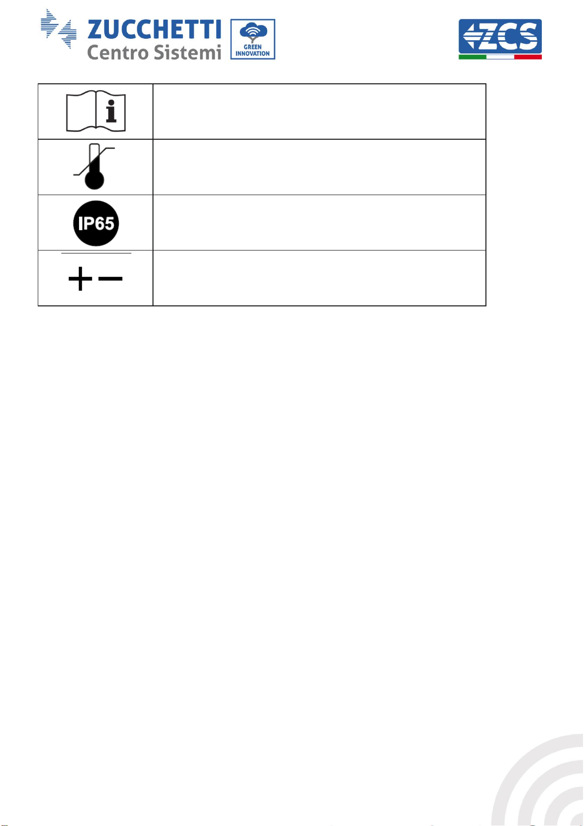
Read this manual before installing the inverter.
Indication of the allowable temperature range
Degree of protection of the equipment according to the IEC 70-1
standard (EN 60529 June 1997).
Positive pole and negative pole of the input voltage (DC).
2. Product features
General information in this chapter
Product dimensions
The field of use and overall dimensions of the 1.1K-3K TL inverters are indicated in this section.
Function description
It describes how the 1.1K-3K TL inverters and their internal operating modules work.
Efficiency curve
It describes the efficiency curves of the inverter.
2.1. Product presentation
Field of use
The 1.1K-3K TL inverters are grid-connected photovoltaic inverters equipped with a single MPPT channel, capable
of converting the direct current generated by the photovoltaic strings into single-phase sine wave alternating
current and feeding the energy to the public electricity grid. An AC circuit breaker (see chapter 4.4) and DC circuit
breaker must be used as disconnecting devices and must always be easily accessible.
10 / 61
Page 11

Identification: MD-AL-GI-00
Rev. 4.0 of 31.01.18 - Application: GID
Manual of 07/06/2019 Rev. 2.1 “User Manual for 1.1K-3K TL”
Figure 2 – Grid-connected photovoltaic system
The 1.1K-3K TL inverters can only be used with photovoltaic modules that do not require one of the poles to
be grounded. The input current and voltage of the PV strings must not exceed the limits specified in the
technical specifications. Only photovoltaic modules can be connected to the input of the inverter (do not
connect batteries or other power supply sources).
• Accessories and optional components of the inverter should be chosen by a qualified technician who is
familiar with the installation conditions.
• Overall dimensions: L x W x H = 405.5 mm x 314 mm x 135.5 mm
Figure 3 – Front, side and back view of the inverter and bracket
11 / 61
Page 12

Identification: MD-AL-GI-00
Rev. 4.0 of 31.01.18 - Application: GID
Manual of 07/06/2019 Rev. 2.1 “User Manual for 1.1K-3K TL”
Labels on the inverter
Figure 4 – Do not remove the label on the side of the inverter
2.2. Description of functions
The DC power generated by the PV modules is filtered through the input board before entering the power
board. The input board also has the function of detecting the insulation impedance and the DC input
voltage/current. The power board converts the DC power into AC power. The current converted into AC is
filtered through the output board and is then fed into the grid. The output board also has the function of
measuring the grid and GFCI voltage/current, and acts as an output insulation relay. The control provides
the auxiliary power supply, controls the operating status of the inverter and shows it on the display. The
display also shows the error codes when the inverter is not functioning properly. At the same time, the
control board can activate the protection relay in order to disconnect the inverter from the grid and protect
the internal components.
Inverter functions
A. Feeding reactive power into the grid
The inverter is able to produce reactive power and feed it into the grid through the setting of the Power
Factor. The feed-in management can be controlled directly by the grid company through a dedicated RS485
interface.
B. Limiting the active power fed into the grid
If enabled, the inverter can limit the amount of active power fed into the grid at the desired value (expressed
as a percentage).
C. Automatic power reduction when grid is over frequency
When the grid frequency is higher than the limit set, the inverter reduces the output power in order to
ensure the stability of the grid.
D. Data transmission
The inverter (or a group of inverters) can be monitored remotely via an advanced communication system
based on a RS485 interface or via Wi-Fi.
E. Software update
A microSD card is used to update the firmware.
12 / 61
Page 13
Identification: MD-AL-GI-00
Rev. 4.0 of 31.01.18 - Application: GID
Manual of 07/06/2019 Rev. 2.1 “User Manual for 1.1K-3K TL”
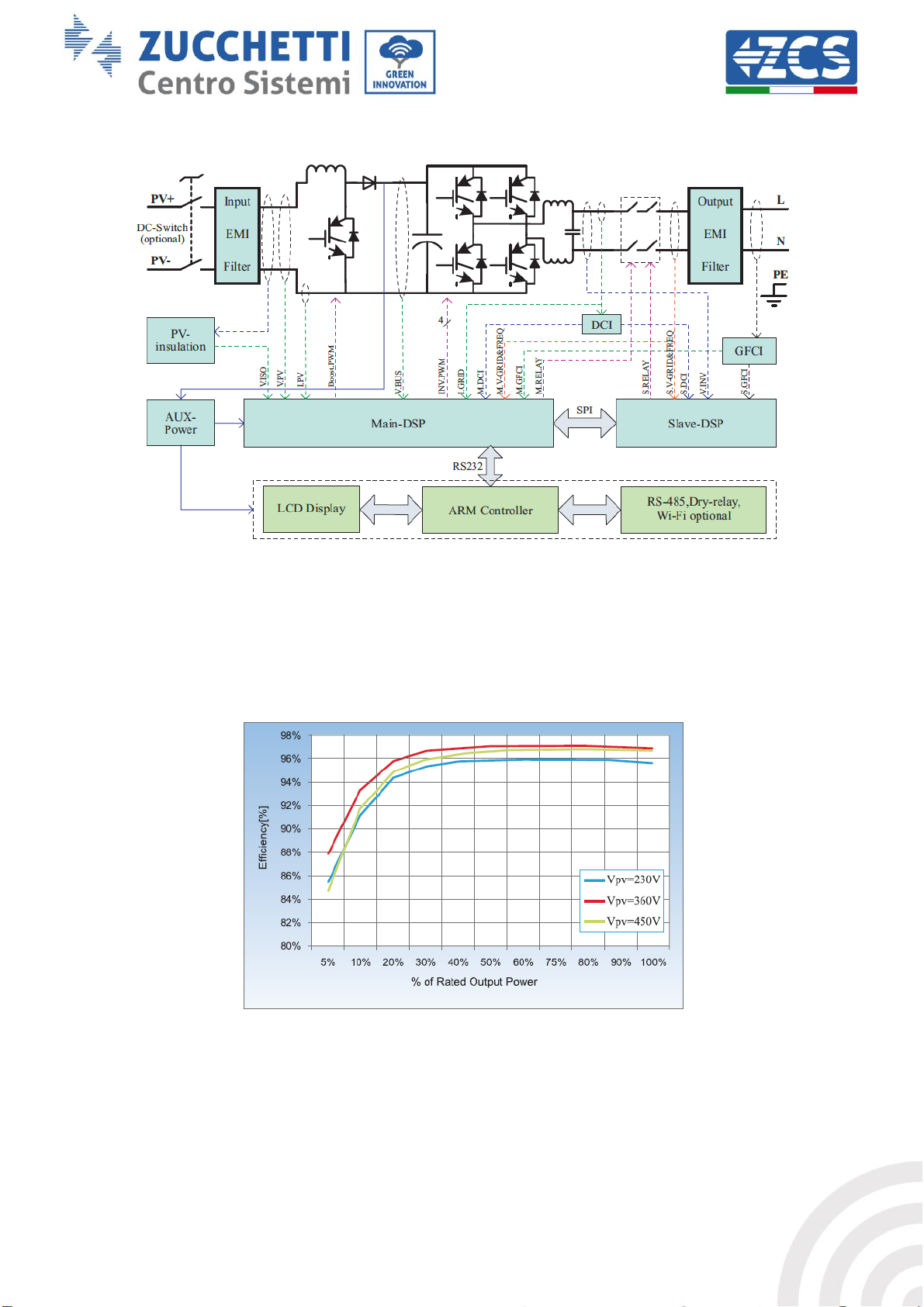
Wiring diagram
Figure 5 – Block diagram of the 1.1K-3K TL inverter
2.3. Efficiency curve
Efficiency curve for a Azzurro ZCS 3000 TL model
Figure 1 – Efficiency curve for an Azzurro ZCS 3000 TL inverter
13 / 61
Page 14

Identification: MD-AL-GI-00
Rev. 4.0 of 31.01.18 - Application: GID
Manual of 07/06/2019 Rev. 2.1 “User Manual for 1.1K-3K TL”
DO NOT install 1.1K-3K TL inverters near flammable materials.
DO NOT install 1.1K-3K TL inverters in an area where flammable or explosive
materials are stored.
Danger
The housing and heat sink may become very hot while the inverter is running, DO NOT
install the inverter in places where they may be touched inadvertently.
Warning
Consider the weight of the inverter during transportation and installation.
Choose an appropriate mounting position and surface.
Attention
3. Installation
General information in this chapter
This chapter describes how to install the 1.1K-3K TL inverter.
Installation notes:
3.1. Installation process
Figure 7 – Installation steps
3.2. Checks before installation
Checking the outer packaging
The packaging materials and components may be damaged during transportation. Therefore, please check
the materials of the outer packaging before installing the inverter. Check the surface of the box for external
damage such as holes or tears. If any kind of damage is detected, do not open the box containing the inverter
and contact the supplier and transport company as soon as possible.
It is recommended to remove the packaged materials from the box 24 hours before installing the inverter.
Checking the product
After removing the inverter from its packaging, check that the product is intact and complete. If any damage
is found or there are no components, contact the supplier and transport company.
14 / 61
Page 15

Identification: MD-AL-GI-00
Rev. 4.0 of 31.01.18 - Application: GID
Manual of 07/06/2019 Rev. 2.1 “User Manual for 1.1K-3K TL”
1 Photovoltaic inverter
1 mounting bracket
1 + input terminal
1 - input terminal
1 Metal terminal for + DC
power cables
1 Metal terminal for - DC
power cables
2 M5 hexagonal screws
10 M6 flat washers
7 expansion plugs (2
spares)
5 self-tapping screws
1 user manual
1 warranty
1 certificate
1 AC output connector
Contents of the packaging
Carefully check the contents of the packaging before installation, making sure that no element inside the
packaging is missing or damaged.
The package will contain the following components:
15 / 61
Page 16

Identification: MD-AL-GI-00
Rev. 4.0 of 31.01.18 - Application: GID
Manual of 07/06/2019 Rev. 2.1 “User Manual for 1.1K-3K TL”
No.
Tool
Function
1
Drill
Recommended drill bit: 6 mm
To drill holes in the wall for
fixing the bracket
2 Screwdriver
To screw and unscrew screws for
the various connections
3 Wire stripping tool
To prepare the cables for wiring
4
Adjustable spanner (opening
greater than 32 mm)
To tighten the bolts
5 4 mm Allen key
To screw the inverter to the wall-
mounting bracket and to open
the front cover of the inverter
6 RJ45 crimping tool
To crimp the RJ45 connectors for
the communication cables
7 Rubber hammer
To insert the expansion plugs
into the wall holes
8 MC4 removal tool
To remove the DC connectors
from the inverter
9 Diagonal pliers
To cut and tighten the cable ends
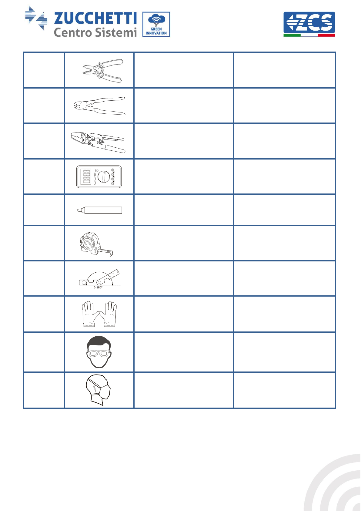
3.3. Installation tools
The following tools are required for installation of the inverter and electrical connections; therefore, they
must be prepared before installation.
16 / 61
Page 17
Identification: MD-AL-GI-00
Rev. 4.0 of 31.01.18 - Application: GID
Manual of 07/06/2019 Rev. 2.1 “User Manual for 1.1K-3K TL”
10 Wire stripping tool
To remove the outer sheath of
the cables
11 Cable cutter
To cut the power cables
12 Crimping tool
To crimp the power cables
13 Multi-meter
To check the voltage and current
values
14 Marking pen
To mark the wall for better fixing
precision
15 Measuring tape
To measure the distances
16
Level
To make sure the bracket is level
17 ESD gloves
Protective clothing
18 Safety goggles
Protective clothing
19 Protection mask
Protective clothing
17 / 61
Page 18

Identification: MD-AL-GI-00
Rev. 4.0 of 31.01.18 - Application: GID
Manual of 07/06/2019 Rev. 2.1 “User Manual for 1.1K-3K TL”
3.4. Installation position
Choose an appropriate installation location for the inverter.
Follow the requirements below to determine the installation position.
Figure 8 – Requirements for installing a single inverter
18 / 61
Page 19

Identification: MD-AL-GI-00
Rev. 4.0 of 31.01.18 - Application: GID
Manual of 07/06/2019 Rev. 2.1 “User Manual for 1.1K-3K TL”
Figure 9 – Requirements for installing multiple inverters
For safety reasons, ZCS Spa and/or its partners may not carry out any technical repairs or maintenance
work, or move the inverter from and to the ground, if it is installed at a height of more than 180 cm from the
ground.
Inverters installed at higher heights must be moved to the ground before they can be repaired or serviced.
3.5. Moving the 1.1K-3K TL inverter
This section describes how to move the inverter correctly
1) Open the packaging and remove the protective cover in polystyrene, insert your hands into the slots on
both sides of the inverter and take a hold of it, as shown in figures 10 and 11.
Figure 10 – Removing the polystyrene protections
19 / 61
Page 20

Identification: MD-AL-GI-00
Rev. 4.0 of 31.01.18 - Application: GID
Manual of 07/06/2019 Rev. 2.1 “User Manual for 1.1K-3K TL”
To prevent damage and personal injury, hold the inverter firmly when moving, as
it is a heavy piece of equipment.
Do not position the inverter with the input/output terminals in contact with other
surfaces, as these are not designed to support the weight of the inverter. Always
position the inverter horizontally.
When placing the inverter on the floor, make sure to place a support under the
unit to protect its front door.
Attention
Figure 11 – Removing the inverter from its packaging
2) Lift the inverter from its packing box and move it to the installation position, then remove the
polystyrene protections.
3.6. Installing the 1.1K-3K TL inverter
1) Correctly position the mounting bracket on the wall, using a level to ensure that it is straight; mark the
five holes using a suitable marker pen. Keeping the hammer drill perpendicular to the wall and avoiding
any sudden movements when drilling, drill the five holes at the points marked on the wall using a 6 mm
drill bit. In case of errors during drilling, it is necessary to reposition the holes.
2) Insert the plugs horizontally into the holes made, paying attention to the force and depth with which
they are inserted (make sure the plug completely enters the hole).
3) Align the mounting bracket with the position of the holes and fix it to the wall using the screws and flat
washers supplied, tightening them properly.
4) Place the inverter on the mounting bracket
5) Secure the inverter to the mounting bracket with the M5 bolt to ensure stability.
6) (OPTIONAL) Depending on the customer’s requirements, the inverter can be locked to the mounting
bracket with a safety lock (not supplied with the kit).
20 / 61
Page 21

Identification: MD-AL-GI-00
Rev. 4.0 of 31.01.18 - Application: GID
Manual of 07/06/2019 Rev. 2.1 “User Manual for 1.1K-3K TL”
The inverter must be installed and serviced by professional technicians or electricians.
Attention
The PV modules generate electricity when exposed to sunlight, which can pose a risk
of electric shock. Before connecting the DC input power cord, be sure to disconnect
the strings via the appropriate disconnecting devices.
Danger
Figure 12 - Steps for installing the inverter on the wall
4. Electrical connections
General information in this chapter
This chapter describes the electrical connections of the 1.1K-3K TL inverter. Carefully read this section
before connecting the cables.
NOTE:
Before making any electrical connections, ensure that the DC circuit breaker is switched off. Please note that
the capacitors in the inverter may remain electrically charged after the DC circuit breaker has been switched
off. Therefore, it is necessary to wait at least 5 minutes to allow the capacitor to discharge completely.
21 / 61
Page 22

Identification: MD-AL-GI-00
Rev. 4.0 of 31.01.18 - Application: GID
Manual of 07/06/2019 Rev. 2.1 “User Manual for 1.1K-3K TL”
The maximum open-circuit voltage of the photovoltaic string must be less than 500 V.
The 1.1K-3K TL series has only one independent input channel (MPPT). All the
photovoltaic modules connected to it must be of the same model so as to have the
same rated electrical characteristics (Isc, Voc, Im, Vm, Pm and temperature
coefficients) and be positioned in the same orientation (solar azimuth and inclination
angle).
Note
The inverter does not have a transformer, therefore the positive pole and
negative pole of the photovoltaic string does NOT need to be grounded.
Otherwise, the inverter may fail. All non-current-carrying metal parts (such as
the PV module frame, PV rack, housing of the combiner box, and housing of the
inverter) in the PV power system must be connected to the ground.
Attention
4.1. Electrical connections
Figure 13 – Steps for connecting the cables
4.2. Ground cable connections (PGND)
Connect the 1.1K-3K TL inverter to the ground electrode using ground protection cables (PGND).
Prerequisites:
Prepare the PGND cables to be connected (outdoor power cables with a cross-section of 4 mm2 are
recommended for grounding purposes). It is recommended to use yellow-green cables for better
identification.
Procedure:
1) Remove an adequate length of the external insulation layers using a wire stripper, as shown in figure 14.
Note: L2 is approximately 2-3 mm longer than L1
22 / 61
Page 23

Identification: MD-AL-GI-00
Rev. 4.0 of 31.01.18 - Application: GID
Manual of 07/06/2019 Rev. 2.1 “User Manual for 1.1K-3K TL”
Figure 14 – Preparing the ground cable (1)
2) Insert the exposed wires in the OT terminal using a crimp tool, as shown in figure 15.
Note 1: L3 is the length between the insulation layer of the ground cable and the crimped part. L4 is the
distance between the crimped part and the conductor wires protruding from the crimped part.
Note 2: The cavity formed after the conductor has been crimp must completely wrap the conductor wires.
The core of the wire must be in close contact with the terminal.
Figure 15 – Preparing the ground cable (2)
3) Install the crimped OT terminal and flat washer using the M5 screw in the hole located on the
inverter heatsink, as shown in the figure; tighten the screw to a torque of 3 Nm using an Allen key.
Figure 16 – Connecting the ground terminal
23 / 61
Page 24

Identification: MD-AL-GI-00
Rev. 4.0 of 31.01.18 - Application: GID
Manual of 07/06/2019 Rev. 2.1 “User Manual for 1.1K-3K TL”
Make sure that the following information is observed. Otherwise, there is a risk of
fire.
The modules connected in series in each string must have the same
specifications.
The open-circuit voltage for each string must be less than 1000 VDC.
The output power for each PV string must be less than or equal to the
maximum input power allowable for 1.1K-3K TL inverters.
The positive and negative terminals of the PV strings must be connected
respectively to the positive and negative inputs of the input terminal block.
Attention
Before connecting the power supply, be sure to disconnect the generator’s
DC switch. When exposed to the sun, the photovoltaic generator produces a
voltage that can be dangerous!
Before connecting the power supply, make sure that the voltage of the DC
cables is within the permissible operating range and that the DC circuit
breaker switch is open. Otherwise, the high voltage may cause serious
damage.
Danger
Check the polarity of the PV string to ensure the correct connection of the cables
to the string.
Be sure not to connect the positive or negative pole of the PV string to the
ground.
Note
Cross-sectional area (mm2)
Outer diameter of cable (mm)
Range
Recommended value
4.0-6.0
4.0
4. 5 - 7. 8
4.3. Connecting the DC input power cables
Connect the 1.1K-3K TL inverter to the photovoltaic strings using DC input power cables.
Note
Depending on the type of inverter, select the appropriate inverter accessories (cables, fuse holder, fuse,
switch, etc). The inverter associated with the PV array must offer excellent performance and reliable quality.
The open-circuit voltage of the photovoltaic system must be lower than the maximum DC input voltage of
the inverter. The output voltage of the strings must be compatible with the MPPT voltage range.
The positive and negative poles of the panel on the inverter must be connected separately. The power cable
must be suitable for photovoltaic applications.
Table 1 – Recommended specifications for DC input cables
The DC input connectors (MC4) are classified into positive and negative connectors, as shown in the figures
below.
24 / 61
Page 25

Identification: MD-AL-GI-00
Rev. 4.0 of 31.01.18 - Application: GID
Manual of 07/06/2019 Rev. 2.1 “User Manual for 1.1K-3K TL”
Figure 17 – Positive (1) and Negative (2) MC4 connectors
Note
The positive and negative metal terminals are packed together with the positive and negative connectors
respectively. Separate the positive and negative metal terminals after unpacking the inverter so as to avoid
confusing the polarities.
Procedure
1) Remove the cable glands from the positive and negative connectors.
2) Remove an appropriate length of the insulation layer from the positive and negative power cables by
using a wire stripper, as shown in the figure.
Figure 18 - Connecting the DC input power cables (1)
25 / 61
Page 26

Identification: MD-AL-GI-00
Rev. 4.0 of 31.01.18 - Application: GID
Manual of 07/06/2019 Rev. 2.1 “User Manual for 1.1K-3K TL”
Before removing the positive and negative connectors, make sure that the
inverter’s circuit breaker is switched off. If not, the direct current may cause an
electric arc that could result in a fire
Warning
Note: L2 is approximately 2 or 3 mm longer than L1.
3) Insert the positive and negative power cables in the corresponding cable glands.
4) Insert the stripped positive and negative power cables into the positive and negative metal terminals
respectively, and crimp them using a suitable tool. Make sure that the cables are secured so that they
cannot be pulled out with a force of less than 400 N, as shown in figure 19
Figure 19 - Connecting the DC input power cables (2)
5) Insert the crimped power cables into the corresponding seats until you hear a “click” sound. At that
point, the power cables will be snapped into place.
6) Replace the cable glands on the positive and negative connectors and rotate them against the
insulation covers.
7) Insert the positive and negative connectors into the corresponding DC input terminals of the inverter
until you hear a “click” sound, as shown in the figure.
Figure 20 - Connecting the DC input power cables (3)
Removal procedure
To remove the positive and negative connectors from the inverter, insert a removal tool into the bayonet and
press the tool with an appropriate force, as shown in the figure below.
26 / 61
Page 27

Identification: MD-AL-GI-00
Rev. 4.0 of 31.01.18 - Application: GID
Manual of 07/06/2019 Rev. 2.1 “User Manual for 1.1K-3K TL”
Do not use the same AC circuit breaker for multiple inverters.
Do not install loads between the inverter and the AC circuit breaker
The circuit breaker used as a disconnection device should always be
operational and ready to operate.
Warning
Type
1100TL
1600TL
2200TL
2700TL
3000TL
Cable (mm2)
>4
>4
>4
>4
>4
Switch
16A/400V
16A/400V
25A/400V
25A/400V
25A/400V
Figure 21 – Removing the DC connector
4.4. Connecting the AC output power cables
Connect the inverter to the AC power distribution network or power grid using AC power cables.
Context
The AC power cables used for the inverter must be three-pole outdoor cables. For easier installation, use
flexible cables. The table lists the recommended specifications for cables and circuit breakers.
Table 2 – Recommended specifications for AC output cables
Note: For safety reasons, make sure to use correctly sized cables, otherwise the current may cause
excessive heating or overloading, which could result in a fire.
Figure 22 – Do not connect loads between the inverter and circuit breaker
27 / 61
Page 28

Identification: MD-AL-GI-00
Rev. 4.0 of 31.01.18 - Application: GID
Manual of 07/06/2019 Rev. 2.1 “User Manual for 1.1K-3K TL”
Figure 2 – Multi core copper wire
Multi-core copper cables
The cross-section of the power line must be sized in order to
prevent unwanted disconnections of the inverter from the grid
due to high impedance of the cable connecting the inverter to the
point of supply. In fact, excessive impedance could cause an
increase in the AC voltage, which in turn may cause the inverter
to disconnect from the grid. In addition, the AC cable must be
correctly sized to ensure that the loss of power on the cable is
less than 1% of the rated power and to ensure proper
functioning of the anti-islanding protection. The cable length
from the inverter to the grid should not exceed 150 meters.
The figure below shows the relationship between the power loss
in the cable, its length and the cross-section area.
Figure 25 – Relationship between power loss, length and cable cross-section
The 1.1K-3K TL inverters are single-phase output inverters that fully comply with the local grid connection
requirements and safety standards.
The inverters are equipped with AC output connectors with IP66 protection suitable for photovoltaic use;
the installer of the system is responsible for connecting the AC output cable; the figure of the AC connector is
shown below.
28 / 61
Page 29

Identification: MD-AL-GI-00
Rev. 4.0 of 31.01.18 - Application: GID
Manual of 07/06/2019 Rev. 2.1 “User Manual for 1.1K-3K TL”
Figure 26 - AC Output Connector
Cable connection procedure
1) Identify the suitable cables as shown in table 2 and remove an appropriate length of the protective
sheath, as shown in the figure (A: 30~50 mm B: 6~8 m).
Figure 27 – Connecting the AC output cables (1)
2) Disassemble the AC connector as shown in the figure below; insert the AC output cable (with its stripped
insulation layers as shown in step 1) through the PG waterproof cable gland.
Figure 28 – Connecting the AC output cables (2)
3) Connect the AC power cable according to the following criteria:
• Connect the ground wire (yellow-green) to the terminal labelled “PE”, and tighten the cable with an
Allen key;
• Connect the line wire (brown) to the terminal labelled “L”, and tighten the cable with an Allen key;
• Connect the neutral wire (blue) to the terminal labelled “N”, and tighten the cable with an Allen key;
29 / 61
Page 30

Identification: MD-AL-GI-00
Rev. 4.0 of 31.01.18 - Application: GID
Manual of 07/06/2019 Rev. 2.1 “User Manual for 1.1K-3K TL”
Communication port
RS485
I/O
CT
Cable cross-section
0.5-1.5 mm2
0.5-1.5 mm2
0.5-1.5 mm2
Outer diameter
2.5~6 mm
2.5~6 mm
2.5~6 mm
Figure 29 – Connecting the AC output cables (3)
4) Secure the clamping cable gland by turning it clockwise, as shown below; make sure that all the wires
are securely connected
5) Connect the AC output connector to the output terminal of the inverter; turn the AC connector in a
clockwise direction until the fixing device reaches its intended position, as shown below:
Figure 30 – Connecting the AC output cables (4)
4.5. Connecting the communication cables
Connecting the communication port
Note: The wiring procedure is the same for the RS485 input, I/O input and CT input. This chapter describes
the steps to be followed for connecting the communication cables.
Table 3 – Recommended specifications for communication cables
1) Remove the central waterproof cover of the communication terminal block using a star screwdriver;
30 / 61
Page 31
Identification: MD-AL-GI-00
Rev. 4.0 of 31.01.18 - Application: GID
Manual of 07/06/2019 Rev. 2.1 “User Manual for 1.1K-3K TL”
Figure 31 – Removing the central cover
2) Turn the waterproof cable gland; remove the cap in the waterproof cable gland;
Figure 32 – Removing the cable glands and stoppers
Note:
The waterproof connectors refer respectively to (from left to right): RS485, Input/Output, CT. Remove the
waterproof connectors according to the communication functions to be used. DO NOT remove the unused
connectors.
3) Choose a suitable cable according to Table 4-2 and remove the outer insulation part using a cable
stripping tool; insert the cable through the cable gland and the waterproof cable glands, as shown in
the figure below:
31 / 61
Page 32

Identification: MD-AL-GI-00
Rev. 4.0 of 31.01.18 - Application: GID
Manual of 07/06/2019 Rev. 2.1 “User Manual for 1.1K-3K TL”
Type
RS485
I/O
CT
Connector
Label
TX-
TX+
5V
GND
I4
I3
I2
I1
CT+
CT-
Function
RS485
differential
signal -
RS485
differential
signal +
Source
Ground
Input 4
Input 3
Input 2
Input 1
CT+
CT-
Figure 33 – Inserting the cables into the appropriate cable gland
4) Choose the terminal according to Table 4-4, connect the cables as shown in the labels and secure
them using a flat screwdriver.
Note: keep the unused terminals for future use.
Table 4 – Description of the communication terminals and their function
Figure 34 – Tightening the terminals on the cables
32 / 61
Page 33

Identification: MD-AL-GI-00
Rev. 4.0 of 31.01.18 - Application: GID
Manual of 07/06/2019 Rev. 2.1 “User Manual for 1.1K-3K TL”
5) Insert the terminal according to the printed label, then tighten the screws to secure the waterproof
cover; turn the cable glands clockwise to tighten.
Figure 35 – Closing the central door
• If multiple inverters need to be connected via the RS485 cable, refer to the following:
The RS485 cables are connected in parallel, so 4 cables are required to make the connection. First connect
the two 485+ cables (TX+) in parallel, then connect the two 485- cables (TX-) in parallel, finally insert them
into the terminal and tighten the screws using a slotted screwdriver.
Note: It is recommended to use two different wire colours to connect TX- (485-) and TX+ (485+). Wires of
the same colour can be connected together to avoid incorrect wire connections.
Figure 36 – Connecting multiple inverters
4.6. Communication systems
The 1.1K-3K TL inverters are equipped with RS485 (standard) and Wi-Fi (optional) communication systems.
These communication systems allow monitoring the main parameters of the inverter (energy generated,
alarms, operating status) through various channels, such as the ZCS AZZURRO portal, ZCS AZZURRO app or
your own monitoring system
33 / 61
Page 34

Identification: MD-AL-GI-00
Rev. 4.0 of 31.01.18 - Application: GID
Manual of 07/06/2019 Rev. 2.1 “User Manual for 1.1K-3K TL”
RS485
For a single inverter it is possible to connect the RS485 port to a terminal such as a PC, using a special RS485 / USB
converter. In this way, it is possible to create a personal system for data acquisition and monitoring of the inverter,
upon request of the Modbus RTU proprietary protocol to ZCS S.p.A.
Alternatively, the RS485 port can be connected to an external datalogger, which is not supplied with the inverter.
In turn, this datalogger can be connected to a router or a modem via Wi-Fi or ethernet cable to allow data to be
sent to the ZCS server.
Figure 36 – Connecting an inverter with RS485
It is possible to connect up to 31 inverters in a daisy chain via the RS485 port. The first in this series must
then be connected to a terminal in the manner described above.
Figure 38 – Connecting multiple inverters with RS485
Note 1: The RS485 communication cable must not be longer than 1000 m.
Note 2: When multiple inverters are connected via the RS485 cables, the Modbus address must be set
progressively as described in chapter 6.3.
WI-FI
For a single inverter, it is possible to connect the Wi-Fi adapter found on board the models – WS or integrated in
the basic models to a device capable of receiving wireless signals, such as routers, wi-fi modems and network
extenders. This allows the inverter data to be sent to the ZCS server and the inverter to be monitored remotely.
34 / 61
Page 35

Identification: MD-AL-GI-00
Rev. 4.0 of 31.01.18 - Application: GID
Manual of 07/06/2019 Rev. 2.1 “User Manual for 1.1K-3K TL”
Figure 39 – Connecting an inverter with wi-fi
For a group of inverters, it is possible to connect the different wi-fi cards to a single terminal (router, wi-fi
modem and network extenders). This procedure does not require the setting of a progressive Modbus address
on the various inverters.
Figure 40 – Connecting multiple inverters with Wi-Fi
To ensure proper transmission of the Wi-Fi signal, completely extract the Wi-Fi antenna by following the
procedure below.
1) Loosen the cable gland of the Wi-Fi antenna.
2) Pull out the Wi-Fi antenna for about 5 cm or until the cable gland prevents it from being pulled out
any further.
3) Tighten the cable gland of the Wi-Fi antenna.
Figure 41 – Extracting the Wi-Fi antenna
For more information and instructions on how to configure the communication system, refer to the relevant
technical notes available at www.azzurrozcs.com or contact the ZCS service centre.
35 / 61
Page 36

Identification: MD-AL-GI-00
Rev. 4.0 of 31.01.18 - Application: GID
Manual of 07/06/2019 Rev. 2.1 “User Manual for 1.1K-3K TL”
Make sure that the DC and AC voltage are within the range
permitted by the inverter.
Attention
5. Commissioning the inverter
5.1. Safety inspection before commissioning
Photovoltaic strings
Before turning on the inverter, the photovoltaic string must be examined. Check the open-circuit
voltage of each photovoltaic panel and compare it with the data in the technical datasheet.
- Make sure that the open-circuit voltage of each PV string corresponds to the technical data and that
it is lower than the maximum input voltage permitted by the inverter.
- Make sure that the positive and negative poles are correct.
DC connection
Use the multi-meter to check the voltage on the DC side; check the DC cable, make sure that the
positive and negative poles are not inverted, and are consistent with the positive and negative poles
of the photovoltaic string.
AC connection
Make sure that the AC switch of the inverter is off. Check that the inverter is properly connected to
the grid. Check that the phase voltage is within the correct range. If possible, measure the THD; if
there is too much distortion, the inverter may not operate properly.
5.2. Starting the inverter
1) Turn ON the DC switch on the field panel and on the photovoltaic inverter (if present); wait for the
screen to turn on.
2) Turn ON the AC switch installed on the wall.
When the photovoltaic string generates enough direct current, the inverter will start automatically.
The word “normal” shown on the screen indicates the correct functioning of the inverter.
3) Set the correct country code (refer to chapter 6.3 of this manual).
Note: Different grid operators in different countries require different specifications regarding the grid
connections of PV inverters. Therefore, it is very important to select the correct country code according to
the requirements of the local authorities.
If in doubt, consult the system engineer or a qualified electrician.
Zucchetti Centro Sistemi S.p.A. shall not be held responsible for any consequences resulting from the
incorrect selection of the country code.
If the inverter indicates the presence of any faults, refer to chapter 7.1 of this manual or contact the
Zucchetti Centro Sistemi S.p.A. technical support.
36 / 61
Page 37

Identification: MD-AL-GI-00
Rev. 4.0 of 31.01.18 - Application: GID
Manual of 07/06/2019 Rev. 2.1 “User Manual for 1.1K-3K TL”
6. Operating interface
General information in this chapter
This section describes the display and its operation, as well as the buttons and LED indicators of the 1.1K-3K
TL inverters.
6.1. Operating panel and display
Buttons and LED indicators
Figure 42 – LCD display with buttons and LED indicators
Main buttons:
Menu/Back: to go back or enter the main menu.
Up: to go up or increase the value by 1.
Down: to go down or decrease the value by 1.
OK/Enter: to confirm the selection and enter the menus
Indicator lights:
Status light (GREEN)
o Flashing: wait or status check
o Steady: normal operation
o Off: temporary or permanent error
Warning light (RED)
o Steady: temporary or permanent error
o Off: normal operation
GFCI warning light (RED)
o Steady: indicates GFCI fault
o Off: normal operation
37 / 61
Page 38

Identification: MD-AL-GI-00
Rev. 4.0 of 31.01.18 - Application: GID
Manual of 07/06/2019 Rev. 2.1 “User Manual for 1.1K-3K TL”
6.2. Main interface
The main LCD interface is used to display the statuses of the inverter, information, configuration of
parameters, etc.
Figure 43 – Main interface of the LCD display
The LCD screen displays the power output of the inverter, the input information coming from the PV system,
information relating to errors, etc.
Figure 44 – Indicators in the main interface
A1 – Modbus communication address
A2 – RS485 Communication
A3 – Steady light for active RS485 communication
A4 – Wi-Fi Communication
A5 – Flashing light to indicate over-frequency and power derating status. Steady light to indicate remote
control
A6 – Indicates the energy produced today
A7 – Indicates the energy produced in total
A8 – Steady light to indicate the high temperature of the inverter
A9 – Output power in real time
A10 –Functioning of the MPPT SCAN option.
A11 – Steady light when the input voltage is higher than 100V
A12 –Real-time input voltage value
A13 – Input voltage and current of the string
A14 – Light is on when the state is normal
A15 – Grid voltage
38 / 61
Page 39

Identification: MD-AL-GI-00
Rev. 4.0 of 31.01.18 - Application: GID
Manual of 07/06/2019 Rev. 2.1 “User Manual for 1.1K-3K TL”
A16 – Grid current and frequency (shown alternatively every three seconds).
A17 – Energy produced from 3:00am to 9:00pm today
When the power is turned on, ZCS INNOVATION…. appears on the screen, as shown in the figure below
when the control board is correctly connected to the communication board, the LCD screen will display the
current status of the inverter, as shown in the figure below.
Inverter states include:
Wait: inverter is waiting to Check the state at the end of the reconnection time. In this state, the PV voltage
must be higher than 100 V, the grid voltage must be between the minimum and maximum permissible
limits, as should the other grid parameters; otherwise, the inverter will go into an error state.
Check: inverter is checking the insulation resistance, relays and other safety parameters. It also runs a selftest to ensure that the software and hardware of the inverter are functional. Inverter will go to an error state
if any faults or anomalies are found.
Normal: inverter is functioning properly and is feeding power into the grid. If any faults are found, the
inverter will go into an error state.
Error: inverter has encountered a temporary error. If the error disappears on its own, the inverter will
return to its normal state. If the error continues, please check the inverter according to the error code.
Permanent error: inverter has encountered a permanent error. The installer must debug this type of error
according to the code found in order to bring the inverter back to its proper functioning.
If the control board and communication board are not connected, the interface of the LCD display appears as
shown in the figure below.
39 / 61
Page 40

Identification: MD-AL-GI-00
Rev. 4.0 of 31.01.18 - Application: GID
Manual of 07/06/2019 Rev. 2.1 “User Manual for 1.1K-3K TL”
6.3. Main menu
Press the “Menu/Back” button in the main interface screen to enter the main menu, which will appear as
follows:
(A) Press the “OK” key to enter the “Settings” menu.
The “Settings” menu contains the following sub-menu:
Date and time
Select “1. Date and time” and press “OK” to enter the menu for setting the date/time. First set the date and
then the time using the “Up” and “Down” keys, then press “OK” to move to the next character and confirm.
The date and time are expressed in the format: 20YY – MM - DD HH:MM:SS.
The display will show “OK” if the setting is correct and “Error” in case of an error.
The date and time can be seen in the submenu “4. Time” inside the main menu.
40 / 61
Page 41

Identification: MD-AL-GI-00
Rev. 4.0 of 31.01.18 - Application: GID
Manual of 07/06/2019 Rev. 2.1 “User Manual for 1.1K-3K TL”
Code
country
Code
country
Code
country
00
Germany VDE AR-
N4105
12
Poland
24
Cyprus
01
CEI 0-21 Internal
13
Germany BDEW
25
India
02
Australia
14
Germany VDE
0126
26
Philippines
03
Spain RD1699
15
Italy CEI 0-16
27
New Zealand
04
Turkey
16
UK-G83
28
Brazil
05
Denmark
17
Greek - islands
29
Slovakia
06
Greece - mainland
18
EUEN50438
30
Slovakia SSE
07
Netherlands
19
IEC EN61727
31
Slovakia ZSD
08
Belgium
20
Korea
32
CEI 0-21 Areti
09
UK-G59
21
Sweden
33-49
Reserved
10
China
22
General Europe
11
France
23
CEI 0-21 External
Clear Energy
Select “2. Clear Energy” and press “OK” to enter the menu for deleting the energy data and in particular the
energy production daily and in total, which is shown in the main interface. Press “OK” to start the procedure;
the display will show “Enter PWD!”, press “OK” to enter the password. Enter the password “0001” using the
“Up” and “Down” keys to select the number and “OK” to move to the next one. Confirm. If the display shows
“Incorrect, try again,” press the “Back” key and enter the password again. When the password entered is
correct, the inverter will delete the data relating to the energy products and the display will show “OK” if the
setting is successful.
Clear Events
Select “3. Clear Events” and press “OK” to enter the menu for clearing historical events, i.e. to clear all error
warnings present in the “List of historical events” submenu. Press “OK” to start the procedure; the display
will show “OK” if the procedure is successful.
Set Country
Select “4. Set Country” and press “OK” to enter the menu for setting the national grid connection regulations.
If “Setting Disabled” appears on the display, go to step 7 “Enable Country” to enable this function. After
enabling the function, repeat the steps described above and set the code for the desired country using the
“Up” and “Down” keys, confirming with “OK”; the display will show “OK” if the setting is successful. The
current country code can be checked from the “System Info” menu.
Note: The change of the country code will take effect after the next start-up of the inverter.
For more information and to know the country regulations on board the inverter, refer to the following table.
Table 5 – Country Codes
41 / 61
Page 42

Identification: MD-AL-GI-00
Rev. 4.0 of 31.01.18 - Application: GID
Manual of 07/06/2019 Rev. 2.1 “User Manual for 1.1K-3K TL”
Enable country
Select 7 “Enable country” and press “OK” to enter the menu for enabling the selection of the country code. The
display will show “Enter PWD!”, press “OK” to enter the password. Enter the password “0001” using the “Up”
and “Down” keys to select the number and “OK” to move to the next one. Confirm. If the display shows
“Incorrect, try again,” press the “Back” key and enter the password again. When the password has been
entered correctly, you can enter the menu.
This operation must be carried out if you want to change the Country code and it has not been changed
during the last 24 hours of operation of the inverter.
Set Energy
Select 8 “Set Energy” and press “OK” to enter the menu for setting the energy already produced by the
photovoltaic system. The display will show “Enter PWD!.” Press “OK” to enter the password “0001” using the
“Up” and “Down” keys to select the number and “OK” to move to the next digit. If the display shows
“Incorrect, try again,” press the “Menu/Back” key and enter the password again. When the password has
been entered correctly, you can enter the menu. You can now set the amount of energy already produced by
the system before installing the current inverter, which is visible from the main interface.
Modbus address
Select 9 “ModBusAddress” and press “OK” to enter the menu for selecting the communication address.
Use the “Up” and “Down” keys to select the number and “OK” to move to the next one, and confirm.
After setting the address, press “OK.”
The Modbus address indicates the address with which the inverter sends its data to the monitoring
server. Address 01 is used for single inverters; if you want to extend the monitoring to multiple
inverters, progressive communication addresses will be used.
Note: make sure that the address entered is never 00, because this setting would exclude the
possibility of communication between the inverter and Wi-Fi network.
Language
Select 10 “Language” and press “OK” to enter the menu for selecting the language. Select the language
using the “Up” and “Down” keys; then press “OK” to confirm.
If the setting is successful, “OK” will be displayed; otherwise, “Error” will be displayed.
A faster way to change the language is to press the “Menu/Back” key and the “OK” key at the same time.
In the current firmware version (V5.00), the available languages are: Chinese, English, Italian, German,
French and Portuguese; future firmware updates may add additional languages.
Initial parameters
The user can change the start parameters directly from the LCD display. The user must first copy the TXT
files to the SD card. These files can be requested from Zucchetti Centro Sistemi Spa technical support.
Select 11 “InitParameters” and press “OK” to enter the menu for setting the start parameters. The display
will show “Enter PWD!”, press “OK” to enter the password. Enter the password “0001” using the “Up” and
“Down” keys to select the number and “OK” to move to the next one, and confirm. If the display shows
“Incorrect, try again,” press the “Back” key and enter the password again. When the password entered is
correct, you can enter the menu. The new start parameters will now be loaded onto the inverter
automatically.
If the setting is successful, “OK” will be displayed; otherwise, “Error” will be displayed.
Attention: do not enter this menu if the microSD card is not inserted in the appropriate slot of the inverter
or if the correct TXT files have not been copied to it.
42 / 61
Page 43

Identification: MD-AL-GI-00
Rev. 4.0 of 31.01.18 - Application: GID
Manual of 07/06/2019 Rev. 2.1 “User Manual for 1.1K-3K TL”
Safety Voltage
The user can change the value of the protection voltage directly from the LCD display. The user must first
copy the TXT files to the SD card. These files can be requested from Zucchetti Centro Sistemi Spa technical
support.
Select 12 “Safety V” and press “OK” to enter the menu for setting the protection voltage. The display will
show “Enter PWD!”, press “OK” to enter the password. Enter the password “0001” using the “Up” and
“Down” keys to select the number and “OK” to move to the next one, and confirm. If the display shows
“Incorrect, try again,” press the “Back” key and enter the password again. When the password has been
entered correctly, you can enter the menu. The new protection voltage will now be loaded on the inverter
automatically.
If the setting is successful, “OK” will be displayed; otherwise, “Error” will be displayed.
Attention: do not enter this menu if the microSD card is not inserted in the appropriate slot of the inverter
or if the correct TXT files have not been copied to it.
Safety Hz
The user can change the value of the protection frequency directly from the LCD display. The user must first
copy the TXT files to the SD card. These files can be requested from the Zucchetti Centro Sistemi Spa
technical support.
Select 13 “Safety Hz” and press “OK” to enter the menu for setting the protection frequency. The display will
show “Enter PWD!”, press “OK” to enter the password. Enter the password “0001” using the “Up” and
“Down” keys to select the number and “OK” to move to the next one, and confirm. If the display shows
“Incorrect, try again,” press the “Back” key and enter the password again. When the password entered is
correct, you can enter the menu. The new protection frequency will now be loaded on the inverter
automatically.
If the setting is successful, “OK” will be displayed; otherwise, “Error” will be displayed.
Attention: do not enter this menu if the microSD card is not inserted in the appropriate slot of the inverter
or if the correct TXT files have not been copied to it.
Insulation
The user can change the value of the insulation resistance directly from the LCD display. The user must first
copy the TXT files to the SD card. These files can be requested from Zucchetti Centro Sistemi Spa technical
support.
Select 14 “Insulation” and press “OK” to enter the menu for setting the insulation resistance. The display will
show “Enter PWD!”, press “OK” to enter the password. Enter the password “0001” using the “Up” and
“Down” keys to select the number and “OK” to move to the next one, and confirm. If the display shows
“Incorrect, try again,” press the “Back” key and enter the password again. When the password has been
entered correctly, you can enter the menu. The new insulation resistance will now be loaded on the inverter
automatically.
If the setting is successful, “OK” will be displayed; otherwise, “Error” will be displayed.
Attention: do not enter this menu if the microSD card is not inserted in the appropriate slot of the inverter
or if the correct TXT files have not been copied to it.
Reactive power setting
Select 16 “Reactive Set” and press “OK” to enter the menu for setting the reactive power produced. The
display will show “Enter PWD!”, press “OK” to enter the password. Enter the password “0001” using the “Up”
and “Down” keys to select the number and “OK” to move to the next one, and confirm. If the display shows
43 / 61
Page 44

Identification: MD-AL-GI-00
Rev. 4.0 of 31.01.18 - Application: GID
Manual of 07/06/2019 Rev. 2.1 “User Manual for 1.1K-3K TL”
“Incorrect, try again,” press the “Back” key and enter the password again. When the password has been
entered correctly, you can enter the menu. Now you can use the “Up” and “Down” keys to select the
“1.Enable” or “2.Disable” option and select it with the “OK” key. If the “1.Enable” option is selected, you can
use the “Up” and “Down” keys to select the options “Under-excited”, “Grid Manager”, and “Over-excited”, and
you can indicate the value of the reactive power produced for each of them. If the setting is successful, “OK”
will be displayed; otherwise, “Error” will be displayed.
Power derating
Select 17 “Derating P(W)” and press “OK” to enter the relative menu, from which you can enable the
“Derating” function, i.e. the possibility to set the power produced by the inverter. The display will show
“Enter PWD!”, press “OK” to enter the password. Enter the password “0001” using the “Up” and “Down” keys
to select the digit and “OK” to move to the next one, and confirm. If the display shows “Incorrect, try again,”
press the “Back” key and enter the password again. When the password entered is correct, you can enter the
menu. With the “Up” and “Down” keys you can set the “1. Enable” and “2. Disable” option, and select it with
the “OK” key. If the “1.Enable” option is selected, use the “Up”, “Down” and “OK” keys to select the percentage
value (between 0 and 100) of the maximum power that the inverter will produce; if the solar radiation
allows a greater amount of energy to be produced, the inverter will carry out the necessary operations to
limit the output power to the set value. If the setting is successful, “OK” will be displayed; otherwise, “Error”
will be displayed.
P(GRID) CHECK
Select “18. P(grid) Check” and press “OK” to enter the relative menu, from which you can enable the “Reflux
Power” function, i.e. the possibility to set the maximum power fed into the grid. The display will show “Enter
PWD!”, press “OK” to enter the password. Enter the password “0001” using the “Up” and “Down” keys to
select the number and “OK” to move to the next one, and confirm. If the display shows “Incorrect, try again,”
press the “Back” key and enter the password again. When the password has been entered correctly, you can
enter the menu. With the “Up” and “Down” keys you can set the “1. Enable” and “2. Disable” option, and
select it with the “OK” key. If the “1.Enable” option is selected, you can use the “Up”, “Down” and “OK” keys to
select the value (expressed in kW, up to two decimal places) of the maximum power that the inverter will
feed into the grid. In this way the inverter can feed a maximum power of between 0 kW and the rated power
of the inverter into the national grid, based on the solar radiation available and the domestic consumption. If
the setting is successful, “OK” will be displayed; otherwise, “Error” will be displayed.
Note: To activate the Reflux Power mode in single-phase inverters, it is necessary to install a CT current
sensor, as described in the appropriate procedure.
Fast self-test
1) During normal operation of the inverter, press the “Back” key to enter the main menu.
2) Press the “OK” key to enter the “Settings” menu.
3) Press the “Down” key several times until “19. Fast Self-test” is shown on the screen.
44 / 61
Page 45

Identification: MD-AL-GI-00
Rev. 4.0 of 31.01.18 - Application: GID
Manual of 07/06/2019 Rev. 2.1 “User Manual for 1.1K-3K TL”
4) Press “OK” to start the self-test.
5) The self-test will now start automatically; once completed, press “Down” to display the self-test
results, as shown in the figure.
45 / 61
Page 46

Identification: MD-AL-GI-00
Rev. 4.0 of 31.01.18 - Application: GID
Manual of 07/06/2019 Rev. 2.1 “User Manual for 1.1K-3K TL”
Standard Self-test
1) During normal operation of the inverter, press the “Back” key to enter the main menu.
2) Press the “OK” key to enter the “Settings” menu.
3) Press the “Down” key several times until “20. Standard Self-Test” is shown on the screen.
46 / 61
Page 47

Identification: MD-AL-GI-00
Rev. 4.0 of 31.01.18 - Application: GID
Manual of 07/06/2019 Rev. 2.1 “User Manual for 1.1K-3K TL”
4) Press “OK” to start the self-test.
5) The self-test will now start automatically; once completed, press “Down” to display the self-test
results, as shown in the figure below.
47 / 61
Page 48

Identification: MD-AL-GI-00
Rev. 4.0 of 31.01.18 - Application: GID
Manual of 07/06/2019 Rev. 2.1 “User Manual for 1.1K-3K TL”
P(f) Setting
Select 21 “Set P(f)” and press “OK” to enter the relative menu, from which you can change the active power
according to the grid frequency required by the local regulations. This function may be required by various
regulations for grid-connected inverters. Use the “Up”, “Down” and “OK” keys to set the time delay expressed
in seconds (*.***s) before the changed P active power will intervene.
48 / 61
Page 49

Identification: MD-AL-GI-00
Rev. 4.0 of 31.01.18 - Application: GID
Manual of 07/06/2019 Rev. 2.1 “User Manual for 1.1K-3K TL”
Q(v) Setting
Select 22 “Set Q(v)” and press “OK” to enter the relative menu, from which you can change the reactive
power according to the grid voltage required by the local regulations. This function may be required by
various regulations for grid-connected inverters. Use the “Up”, “Down” and “OK” keys to set the time delay
expressed in seconds (*.***s) before the changed Q reactive power will intervene.
81.S1 Check
Select 23. “81.S1Check” and press “OK” to enter the relative menu, from which it will be possible to enable
the frequency restriction thresholds required in special cases by local regulations. With the “Up” and “Down”
keys you can set the “1. Enable 81.S1” and “2. Disable 81.S1” option, and select it with the “OK” key. The
display will show “OK” if the setting is successful.
Disabled settings
The following functions:
- Remote Control, relating to item “5. Remote Control”
- Relay Command, relating to item “6. Relay Command”
- Relay test, relating to item “15. Relay Test”
cannot be used on this model of inverter; access to these submenus is not permitted either by the installer
or by the end user. ZCS S.p.A. accepts no responsibility deriving from the activation of one of the settings
described above.
(B) Press the “OK” key to enter the “Event List” menu.
The “Event List” menu is used to display the events recorded by the inverter, both historical and in
real time, showing the progressive number of the event, the identification code, the date and time of
its occurrence. The user can access this interface from the LCD display to check the details of the
alarms and alerts. Errors will be listed according to the date and time they occurred, so the most
recent events will be listed first. For more information, refer to the figure below.
Press the “Back” button in the main interface and then the “Up” button, then enter the “2. Event List”
menu. From here you can select the “1. Current Events” menu for the list of current events or “2.
Historical Events” for the list of historical events.
(C) Press the “OK” key to enter the “System Info” menu.
The “System Info” menu contains the following submenus:
49 / 61
Page 50

Identification: MD-AL-GI-00
Rev. 4.0 of 31.01.18 - Application: GID
Manual of 07/06/2019 Rev. 2.1 “User Manual for 1.1K-3K TL”
Inverter type
Use the “Up” and “Down” keys in the “System Info” menu to move, and the “OK” key to enter the “1. Inverter
type” menu. Here you can see the power of the inverter model
Serial number
Use the “Up” and “Down” keys in the “System Info” menu to move, and the “OK” key to enter the “2. Serial
Number” menu. Here you can see the serial number of the inverter.
SW version
Use the “Up” and “Down” keys in the “System Info” menu to move, and the “OK” key to enter the “3. SW
Version” menu. Here you can see the software version.
HW version
Use the “Up” and “Down” keys in the “System Info” menu to move, and the “OK” key to enter the “4. HW
Version” menu. Here you can see the hardware version.
Country
Use the “Up” and “Down” keys in the “System Info” menu to move, and the “OK” key to enter the “5. Country”
menu. Here you can see the country code that has been set.
Power factor
Use the “Up” and “Down” keys in the “System Info” menu to move, and the “OK” key to enter the “7. Power
Factor” menu. Here you can see the value of the power factor.
P(Grid) Feed-in
Use the “Up” and “Down” keys in the “System Info” menu to move, and the “OK” key to enter the “8. P(Grid)
Feed-in” menu. Here you can see the value of the set value of the power fed into the grid.
P(f)
Use the “Up” and “Down” keys in the “System Info” menu to move, and the “OK” key to enter the “9. P(f)”
menu. Here you can see the P(f) value that has been set.
Q(v)
Use the “Up” and “Down” keys in the “System Info” menu to move, and the “OK” key to enter the “10. Q(v)”
menu. Here you can see the Q(v) value that has been set.
Service Code
Use the “Up” and “Down” keys in the “System Info” menu to move, and the “OK” key to enter the “11.
ServiceCode” menu. Here you can see the currently installed firmware version.
(D) Press the “OK” key to enter the “Date and Time” menu.
Press the “Back” key in the main interface and the “Up” or “Down” keys to enter the submenu “4. Date and
Time”, then press “OK” to display the current date and time set on the inverter.
50 / 61
Page 51

Identification: MD-AL-GI-00
Rev. 4.0 of 31.01.18 - Application: GID
Manual of 07/06/2019 Rev. 2.1 “User Manual for 1.1K-3K TL”
(E) Press the “OK” key to enter the “Update Software” menu.
Press the “Back” key in the main interface and the “Up” or “Down” keys to enter the submenu “5. Software
Update”, then press “OK” to enter. The display will show “Enter PWD!.” Press “OK” to enter the password
“0715” using the “Up” and “Down” keys to select the number and “OK” to move to the next digit and confirm.
If the display shows “Incorrect, try again,” press the “Back” key and enter the password again. When the
password has been entered correctly, you can enter the menu and start updating the firmware.
Note: You can check the firmware version currently installed on the inverter from the “Service Code”
submenu found in the “System Info” menu.
IMPORTANT: Do not perform any update operation if there is no microSD card inside the inverter or if the
microSD card does not contain the appropriate update files. Always make sure that the correct update files
are loaded on the microSD card and that the card is correctly inserted in the appropriate slot.
Note: the microSD card is not supplied with the inverter and must be procured by the installer or customer.
The complete and detailed procedure for updating the firmware is described below.
Update requirements
- 4 Gb MicroSD card
- MicroSD to SD adapter or MicroSD to USB adapter for inserting the MicroSD card into the PC.
Firmware update procedure
1. Switch off the ZCS inverter by first disconnecting the AC power supply via the switch installed on the
system, and then disconnecting the DC power supply via the switch located on the side of the
inverter (if equipped) or switch off the system’s disconnecting switch. Wait for the display to turn off
completely.
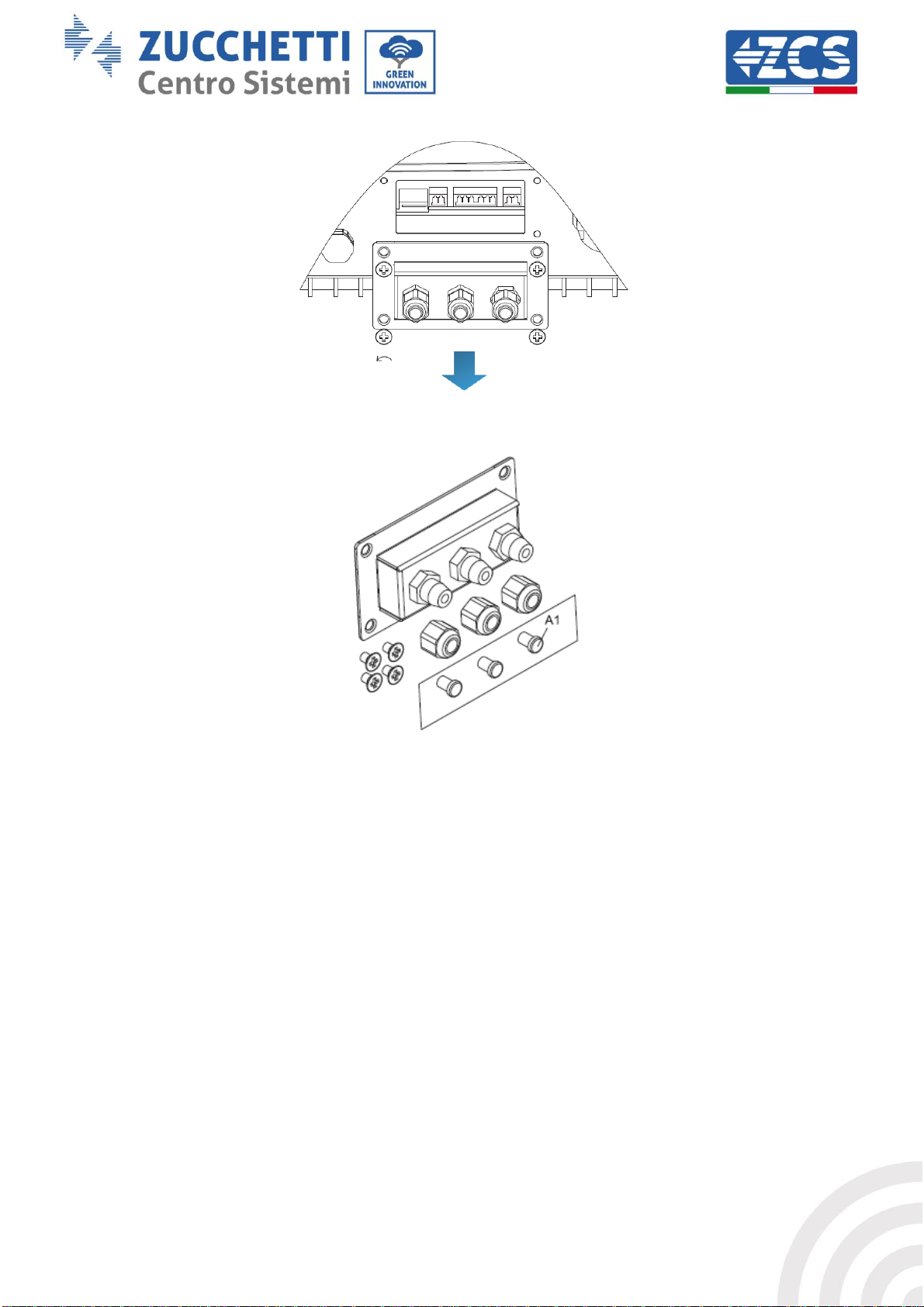
2. Remove the central cover at the bottom of the inverter by unscrewing the four star screws, taking
care to have first loosened the four cable glands.
51 / 61
Page 52

Identification: MD-AL-GI-00
Rev. 4.0 of 31.01.18 - Application: GID
Manual of 07/06/2019 Rev. 2.1 “User Manual for 1.1K-3K TL”
Figure 45 – Removing the central cover
3. Extract (if PRESENT) the microSD card from its slot by pressing lightly on the card and pulling it out
of the inverter. Alternatively, obtain the microSD card yourself. Then insert it into the PC using the
appropriate adaptor.
4. Open the microSD CARD drive and create a new folder with the name firmware, making sure to
match the lowercase and uppercase letters as indicated and checking that there are no spaces. Now
copy the files attached to the email into the firmware folder.
5. Extract the microSD CARD from the PC using the “safely remove hardware” procedure.
6. Insert the microSD CARD in the appropriate slot of the inverter.
Figure 46 – Positioning and removing the microSD card
7. Only supply DC power to the inverter through the appropriate disconnecting switch and wait a few
seconds for the display to come on.
8. From the display, press the “Menu/Back” key (first from the left) to enter the menu, and then the
“OK” key (fourth from the left) to enter the SOFTWARE UPDATE item. Enter the password 0715 and
press “OK” again to start the update.
9. The update process will take about 3 minutes and will run automatically. The following indications
will be followed:
a. DSP1 Update
b. DSP2 Update
c. ARM Update
10. Check that the inverter completes the update correctly and that “INITIALIZING” appears on the
display; the inverter will then start normally. If the update was not successful, one of the following
messages will appear on the display: “COMMUNICATE FAIL”, “UPDATE DSP1 FAIL” or “UPDATE
DSP2 FAIL”; in this case, switch off the inverter, wait one minute and then restart the procedure
from step 7.
11. Once the update has been successfully completed, the country code must be changed: press the
“Menu/Back” key to enter the “Settings” menu, then scroll down to the “Set Country” item and enter
the country code 22.
Note: if the inverter has been running for more than 24 hours, this function must first be enabled
from the “Enable Country” menu, which corresponds to item 6 of the “Settings” menu. Enter the
password 0001.
52 / 61
Page 53

Identification: MD-AL-GI-00
Rev. 4.0 of 31.01.18 - Application: GID
Manual of 07/06/2019 Rev. 2.1 “User Manual for 1.1K-3K TL”
12. Switch off the inverter via the disconnecting switch on the DC line.
13. Restart the inverter by supplying DC power and enter the country selection menu again; set the
country code according to the grid standard in your country (e.g. CEI-021 INT, CEI-021 EXT, CEI-016
for Italy).
14. Switch off the system and restart it after waiting a few minutes, as indicated in step 13.
15. The update procedure has now been completed, and the inverter can now be connected to the AC
line by connecting it to the grid. The new firmware version can be checked from the “Service Code”
submenu located inside the “System Info” menu.
53 / 61
Page 54

Identification: MD-AL-GI-00
Rev. 4.0 of 31.01.18 - Application: GID
Manual of 07/06/2019 Rev. 2.1 “User Manual for 1.1K-3K TL”
Error
code
Error name
Error description
Possible solution
ID01
GridOVP
The grid voltage is too
high.
If the alarm occurs occasionally, the
probable cause is that the electric
grid is in an abnormal state.
The inverter will automatically
return to its normal operating state
when the electrical grid is restored to
its normal state.
If the alarm occurs frequently, check
whether the grid voltage/frequency
is within the correct range. If not,
contact technical support. If so, check
the AC circuit breaker and the AC
wiring of the inverter.
If the voltage/frequency is within the
acceptable range and the AC wiring is
correct while the alarm occurs
repeatedly, contact Technical
Support to change the grid
overvoltage, undervoltage, over-
frequency and under-frequency
protection points after obtaining
approval from the local grid operator.
ID02
GridUVP
The grid voltage is too
low.
ID03
GridOFP
The grid frequency is
too high.
ID04
GridUFP
The grid frequency is
too low.
7. Troubleshooting and maintenance
7.1. Troubleshooting
This section contains information and procedures on how to troubleshoot any faults and errors that may
occur during operation of the 1.1K-3K TL inverter.
If you have any problems with the inverter, follow these steps.
Check the warning messages and error codes on the information panel of the inverter. Record them
before any further operation.
If the inverter does not display any errors, perform the following checks:
- Is the inverter found in a clean, dry and properly ventilated place?
- Is the DC switch closed?
- Are the cables correctly sized and as short as possible?
- Are the input/output connections and the cables in good condition?
- Are the configuration settings correct for the type of installation?
Follow the steps below to display the recorded alarms:
Press “Menu/Back” to enter the main menu from the standard interface. Select “Event List” in the menu
screen, then press “OK” to access the list of alarms and errors.
Information on event list
54 / 61
Page 55

Identification: MD-AL-GI-00
Rev. 4.0 of 31.01.18 - Application: GID
Manual of 07/06/2019 Rev. 2.1 “User Manual for 1.1K-3K TL”
ID09
PvOVP
The input voltage is
too high.
Check whether too many PV modules
have been connected in series per
string: the voltage (Voc) of the PV
string is therefore higher than the
maximum input voltage of the
inverter. In this case, adjust the
number of photovoltaic modules
mounted in series to decrease the
voltage of the PV string, so that it falls
within the input voltage range of the
inverter. The inverter automatically
returns to its normal operating state
after the string has been corrected.
ID12
GFCIFault
Faulty automatic
differential circuit
breaker.
If the fault occurs occasionally, the
probable cause is that the external
circuits have temporary faults.
The inverter automatically returns to
its normal operating state after the
fault has been fixed.
If the fault repeats itself often and
lasts for a long time, check whether
the insulation resistance between the
PV string and the ground is too low,
then check the insulation conditions
of the PV cables.
ID14
HwBoostOCP
The input current is
too high and has
caused the hardware
protection to be
activated.
Check if the input current is higher
than the maximum input current
allowed by the inverter, then check
the input wiring; if both are correct,
contact Technical Support.
ID15
HwAcOCP
The grid current is
too high and has
caused the hardware
protection to be
activated.
ID15-ID22 are internal faults of the
inverter; turn off the “DC switch”,
wait 5 minutes, and then turn it back
on again. Check that the fault is no
longer present. If this is not the case,
contact Technical Support
ID16
AcRmsOCP
The grid current is
too high.
ID20
GFCIDeviceFault
GFCI sampling error.
ID22
HwAuxPowerFault
Auxiliary voltage
error
ID26
BusOVP
The bus voltage is too
high.
Internal fault of the inverter; turn off
the “DC switch”, wait 5 minutes, and
then turn it back on again. Check that
the fault is no longer present. If this is
not the case, contact Technical
Support
ID28
DciOCP
The DCI is too high.
Check the configuration of the input
mode (parallel mode / independent
mode) of the inverter, as indicated in
Section 6.3 (C) “6 Input mode” of this
user manual; if this setting is
incorrect, change it according to
Section 6.3 (A) “10. Configuration of
55 / 61
Page 56

Identification: MD-AL-GI-00
Rev. 4.0 of 31.01.18 - Application: GID
Manual of 07/06/2019 Rev. 2.1 “User Manual for 1.1K-3K TL”
the input mode” of this manual. If the
input mode is correct, turn off the
“DC switch”, wait 5 minutes and then
turn it back on again. Check that the
fault is no longer present. If this is not
the case, contact Technical Support
ID29
SwOCPInstant
The grid current is
too high.
Internal fault of the inverter; turn off
the “DC switch”, wait 5 minutes and
then turn it back on again. Check that
the fault is no longer present. If this is
not the case, contact Technical
Support
ID30
SwBOCPInstant
The input current is
too high.
Check if the input current is higher
than the maximum input current
allowed by the inverter, then check
the input wiring; if both are correct,
contact Technical Support.
ID49
ConsistentFault_VGrid
The grid voltage
sampling value
between the master
DSP and slave DSP is
not the same.
ID49-ID55 are internal faults of the
inverter; turn off the “DC switch”,
wait 5 minutes, and then turn it back
on again. Check that the fault is no
longer present. If this is not the case,
contact Technical Support
ID50
ConsistentFault_FGrid
The grid frequency
sampling value
between the master
DSP and slave DSP is
not the same.
ID51
ConsistentFault_DCI
The current sampling
value of the automatic
differential circuit
breaker (DCI)
between the master
DSP and the slave DSP
is not the same.
ID52
ConsistentFault_GFCI
The current sampling
value of the automatic
differential circuit
breaker (GFCI)
between the master
DSP and the slave DSP
is not the same.
ID53
SpiCommLose
SPI communication
error between the
master DSP and the
slave DSP.
ID54
SciCommLose
SCI communication
error between the
master DSP and the
slave DSP.
ID55
RelayTestFail
Relay fault.
56 / 61
Page 57

Identification: MD-AL-GI-00
Rev. 4.0 of 31.01.18 - Application: GID
Manual of 07/06/2019 Rev. 2.1 “User Manual for 1.1K-3K TL”
ID56
PvIsoFault
The insulation
resistance is too low.
Check the insulation resistance
between the photovoltaic string and
the ground, if the insulation is low,
rectify the fault.
ID58
OverTempFault_Boost
The boost
temperature is too
high.
Make sure that the installation
position and the installation method
meet the requirements of Section 3.4
of this manual.
Check if the ambient temperature in
the installation location exceeds the
allowed limit. If so, improve the
ventilation to reduce the
temperature.
ID59
OverTempFaultEnv
Ambient temperature
is too high.
ID65
UnrecoverHwAcOCP
The grid current is
too high and has
caused an irreparable
hardware failure.
ID65-ID70 are internal faults of the
inverter; turn off the “DC switch”,
wait 5 minutes, and then turn it back
on again. Check that the fault is no
longer present. If this is not the case,
contact Technical Support
ID66
UnrecoverBusOVP
The bus voltage is too
high and has caused
an irreparable fault.
ID70
UnrecoverOCPInstant
The grid current is
too high and has
caused an irreparable
fault.
ID74
UnrecoverIPVInstant
The input current is
too high and has
caused an irreparable
fault.
ID74-ID77 are internal faults of the
inverter; turn off the “DC switch”,
wait 5 minutes and then turn it back
on again. Check that the fault is no
longer present. If this is not the case,
contact Technical Support
ID75
UnrecoverWRITEEEPROM
The EEPROM is
unrecoverable.
ID76
UnrecoverREADEEPROM
The EEPROM is
unrecoverable.
ID77
UnrecoverRelayFail
The relay has
generated a
permanent fault.
ID81
OverTempDerating
The inverter has been
derated because the
temperature is too
high.
Make sure that the installation
position and the installation method
meet the requirements of Section 3.4
of this manual.
Check if the ambient temperature in
the installation location exceeds the
allowed limit. If so, improve the
ventilation to reduce the
temperature.
57 / 61
Page 58

Identification: MD-AL-GI-00
Rev. 4.0 of 31.01.18 - Application: GID
Manual of 07/06/2019 Rev. 2.1 “User Manual for 1.1K-3K TL”
ID82
OverFreqDerating
The inverter has been
derated because the
grid frequency is too
high.
The inverter automatically reduces
the output power when the
frequency of the electrical grid is too
high.
ID94
The software version is not
suitable
The software of the
control board and
communication board
do not match.
Contact Technical Support to update
the software.
ID95
Faulty EEPROM
communication board.
The EEPROM
communication board
is faulty.
ID95-ID96 are internal faults of the
inverter; turn off the “DC switch”,
wait 5 minutes and then turn it back
on again. Check that the fault is no
longer present. If this is not the case,
contact Technical Support
ID96
Faulty RTC clock chip
The RTC clock chip is
faulty.
ID97
Invalid country
The country selected
in not valid.
Check the configuration of the
country, as indicated in Section 6.3
(C) “5. Country” of this user manual;
if it is not correct, change it according
to Section 6.3(A) “4. Configuration of
country code” of this manual.
ID98
Faulty SD
The SD card is faulty.
Replace the microSD card.
ID99 –
ID100
Reserved
Reserved
7.2. Maintenance
Inverters generally do not require daily or routine maintenance. In any case, for proper long-term operation
of the inverter, make sure that the heatsink for cooling the inverter has enough space to ensure adequate
ventilation and that it is not obstructed by dust or other items.
Cleaning the inverter
Please use an air compressor, a soft dry cloth or soft-bristled brush to clean the inverter. Do not use water,
corrosive chemical substances or aggressive detergents to clean the inverter. Disconnect the AC and DC
power to the inverter before cleaning.
Cleaning the heatsink
Use an air compressor, a soft dry cloth or soft-bristled brush to clean the inverter. Do not use water, corrosive
chemical substances or aggressive detergents to clean the inverter. Disconnect the AC and DC power to the
inverter before cleaning.
58 / 61
Page 59

Identification: MD-AL-GI-00
Rev. 4.0 of 31.01.18 - Application: GID
Manual of 07/06/2019 Rev. 2.1 “User Manual for 1.1K-3K TL”
Technical specifications
1100TL
1600TL
2200TL
2700TL
3000TL
Input (DC)
Typical power of PV system
1200W
1800W
2400W
2900W
3300W
Number of MPPTs / Number of
strings per MPPT
1 / 1
Maximum DC input voltage
450V
500V
Input activation voltage
100V
120V
Rated DC input voltage
360V
MPPT DC voltage range
80V-450V
100V-500V
DC voltage range at full load
110V-450V
165V-450V
170V-500V
200V-500V
Max input DC current
10A
13A
13.5A
15A
Output (AC)
Rated AC output power
1000W
1550W
2100W
2600W
3000W
Maximum AC power
1000VA
1550VA
2100VA
2600VA
3000VA
Maximum AC current
4.5A
7A
9.5A
11.5A
13A
Rated AC voltage
L/N/PE, 220, 230, 240 V
8. Uninstalling
8.1. Steps for uninstalling the inverter
Disconnect the inverter from the AC grid.
Switch off the DC switch
Wait 5 minutes
Remove the DC connectors
Remove the AC terminals.
Unscrew the fixing bolt of the bracket and remove the inverter from the wall.
8.2. Packaging
If possible, pack the inverter in its original packaging.
8.3. Storage
Store the inverter in a dry place where the ambient temperature is between -25 and +60°C.
8.4. Disposal
At the end of its life, dispose of the inverter and the packaging materials in places that can manage and
recycle electrical equipment safely.
9. Technical specifications
59 / 61
Page 60

Identification: MD-AL-GI-00
Rev. 4.0 of 31.01.18 - Application: GID
Manual of 07/06/2019 Rev. 2.1 “User Manual for 1.1K-3K TL”
Rated AC voltage range
180V-270V (According to local grid standards)
Rated frequency
50 / 60 Hz
Frequency range
47-53Hz / 57-63 Hz (According to local grid standards)
Active power adjustable range
0-100%
Total harmonic current distortion
<3%
Power factor
1 (adjustable +/-0.8)
Grid feed limit
Feed adjustable from zero to nominal value
Operating performance
Maximum efficiency
97%
97.1%
97.2%
Weighted efficiency (EURO/CEC)
95.2%
95.9%
96.1%
96.4%
96.5%
Consumption at night
<1W
Power start threshold
20W
MPPT efficiency
>99.9%
Protection
DC circuit breaker
Optional (present in models – WS)
Reverse polarity protection
Yes
Overheating protection
Yes
Safety protection
Anti-islanding, RCMU, Ground Fault Monitoring
Safety certifications
CE, CGC, AS47 77,AS3100,VDE4105 ,C10-Cll ,G83/G59, CEI 0-21
Grid connection standards
AS 4777,AS3100, VDE-AR-N 4105, G83/G59, CEI 0-21, C10/11
Standard
Safety standard
IEC 62116, IEC 61727, IEC 61683, IEC 60068-1/2/14/30, IEC 62109-1/2
Grid connection standard
AS 4777, VDE V 0124-100, VDE V 0126-1-1, VDE-AR-N 4105,
EN50438, G83/2, C10/11, RD1699, CEI 0-21
EMC
EN 61000-6-1/2/3/4,
Communication
Communication interfaces
Wi-Fi (only models –WS), RS485 (proprietary protocol), SD card
Additional inputs or connections
Input for current sensor connection
Data storage on SD
25 years
General information
Ambient temperature
-25°C...+60°C (power limit above 45°C)
Topology
Transformerless
Degree of protection
IP65
Relative humidity
0...95% Non-condensing
Maximum operating altitude
2000m
Acoustic emission
<25dB@1m
Weight
11kg
12kg
Cooling system
Natural
Dimensions
405*314*135 mm
User interface
LCD display
Warranty
10 years
60 / 61
Page 61

Identification: MD-AL-GI-00
Rev. 4.0 of 31.01.18 - Application: GID
Manual of 07/06/2019 Rev. 2.1 “User Manual for 1.1K-3K TL”
10. Warranty
Zucchetti Centro Sistemi SpA provides a warranty of 10 years from the date of installation on the 1.1K-3K TL
inverter, subject to registration on the website https://www.zcsazzurro.com/it/estensione-garanzia. In any
case, the warranty cannot exceed 66 months from the date of delivery of the inverter.
During the warranty period, Zucchetti Centro Sistemi S.p.A. guarantees normal operation of the inverter.
If the inverter is defective or faulty during the warranty period, contact your installer or supplier. If the fault
falls within the responsibility of the manufacturer, Zucchetti Centro Sistemi S.p.A. will provide service and
maintenance free of charge.
Warranty exclusions
Use of the 1.1K-3K TL inverters for any other purpose than the intended one.
Defective or faulty design or installation of the photovoltaic system.
Improper use of the inverter.
Incorrect configuration of the protections on the inverter.
Unauthorised modifications to the inverter.
Damage caused by external factors or force majeure (e.g. lightning, power surges, bad weather, fire,
earthquakes, tsunamis, etc.)
61 / 61
 Loading...