

Page 1

CDMA
ZTE CORPORATION
ZTE Plaza, Keji Road South,
Hi-Tech Industrial Park,
Nanshan District, Shenzhen,
P. R. China
518057
Tel: (86) 755 26771900
Fax: (86) 755 26770801
URL: http://ensupport.zte.com.cn
E-mail: [email protected]
ZXSDR
BS8900
Outdoor Basestation-8900
Hardware Manual
Page 2

LEGAL INFORMATION
Copyright © 2006 ZTE CORPORATION.
The contents of this document are protected by copyright laws and international treaties. Any reproduction or distribution of
this document or any portion of this document, in any form by any means, without the prior written consent of ZTE CORPORATION is prohibited. Additionally, the contents of this document are protected by contractual confidentiality obligations.
All company, brand and product names are trade or service marks, or registered trade or service marks, of ZTE CORPORATION
or of their respective owners.
This document is provided “as is”, and all express, implied, or statutory
claimed, including without limitation any implied warranty of merchantability, fitness for a particular purpose, title or non-infringement. ZTE
information contained herein.
ZTE CORPORATION or its licensors may have current or pending intellectual property rights or applications covering the subject
matter of this document. Except as expressly provided in any written license between ZTE CORPORATION and its licensee,
the user of this document shall not acquire any license to the subject matter herein.
ZTE CORPORATION reserves the right to upgrade or make technical change to this product without further notice.
Users may visit ZTE technical support website http://ensupport.zte.com.cn to inquire related information.
The ultimate right to interpret this product resides in ZTE CORPORATION.
CORPORATION and
its licensors shall not be liable for damages resulting from the use of or reliance on the
warranties, representations
or conditions are dis-
Revision History
Revision No. Revision Date Revision Reason
R1.1
R1.0
Serial Number: sjzl20085453
03/20/2009 Add information of outdoor BBU and RSU
11/30/2008 First Edition
Page 3

Contents
Preface ...............................................................
Cabinet..............................................................
Cabinet Technique
Baseband Power Cabinet Outer Structure........................... 1
Baseband Power Cabinet Inner
Heat Exchanger.......................................................... 3
Transmission Equipment
Baseband
Cable Tray
Lightning Subrack....................................................... 6
Power Supply Subrack................................................. 7
Smog
RF Cabinet Outer
RF Cabinet Inner Structure
RF
Lightning Filter
Storage Battery Cabinet .................................................13
Sensor .............................................................
Subrack
Feature ...............................................
Structure
(Optional)
Subrack ......................................................
.................................................................
Structure ..............................................
..............................................
...............................................................11
(Optional)
...........................................12
........................... 2
............................... 4
Modules...........................................................
BBU Modules.................................................................15
Control and Clock Module
Channel Processing Module (CH).................................. 19
Fabric Switch Module (FS)........................................... 23
Site Alarm Module (SA) ..............................................28
Fan Array Module (FA)................................................30
Power Module
RRU Modules ................................................................ 34
Fan Subrack.............................................................. 34
Power Distribution Subrack .........................................34
Radio System Unit
Power Distribution Module
Fan Control Module (FCE) ...........................................40
(PM)
....................................................31
(RSU)
(CC)
.................................... 15
............................................ 35
(PDM)
.................................39
i
1
1
4
6
8
8
9
15
Page 4

External Cables
External Cable Layout ....................................................43
Baseband Power Cabinet Input Power
Baseband Power Cabinet Grounding Cable ........................45
Baseband Cabinet and Storage Battery Connecting
Cable
...................................................................46
Baseband Subrack DC Input Power Cable..........................46
Serial Port Monitoring Cable from Power Subrack to
Baseband
Baseband Subrack and RF Cabinet Connecting
External Dry Contact of Baseband Subrack........................49
Baseband Subrack and Lightning Subrack Connecting
Cable
...................................................................53
Baseband Subrack Ethernet Cable.................................... 54
GPS Arrester and CC Module Connecting RF Cable..............55
Storage Battery Door Control Cable .................................55
Storage Battery Temperature Monitoring
Storage Battery Water Monitoring Cable ...........................56
E1/T1 Cable on Lightning Subrack LPU .............................56
RF Cabinet DC Input Power Cable ....................................59
GPS Antenna Feeder System
GPS Antenna Feeder System
GPS Antenna ................................................................62
GPS Feeder...................................................................63
GPS Arrester.................................................................64
GPS Feeder Connector....................................................65
GPS Grounding
Main Antenna Feeder
Main Antenna Feeder System
Antenna
Feeder Structure ...........................................................75
.......................................................................75
Outdoor BBU+RSU
Cabinet
........................................................................77
Outdoor BBU+RSU Cabinet Technique
Cabinet Outer Structure .............................................77
Cabinet Inner
Outdoor BBU Cabinet.........................................80
Outdoor RSU Cabinet.........................................81
Fan
Heater
...............................................
Cable
......................44
Subrack
.................................................47
Fiber
...........48
Cable
..................56
...........................
Structure
Kit
.........................................................66
.............................61
System ..........................
Structure
............................69
Cabinet ..............................
Feature
Structure
Box
...........................................................82
.............................................................83
..............................................79
...............77
43
61
69
77
Page 5

Heat Exchanger ................................................83
Modules ....................................................................... 84
Control and Clock Module
Channel Processing Module (CH).................................. 88
Fabric Switch Module (FS)........................................... 92
Site Alarm Module (SA) ..............................................97
Fan Array Module
Power Module
Fan Control Module (FCE)
LPU
.......................................................................
PSU .......................................................................
APM.......................................................................
DPM
......................................................................
1X Channel Process Module with Optical Interface
(CVI)
.............................................................
External
External Cable Layout
DC Power Cable between PSU and BBU/FCE
Equipment AC Input Power
Grounding
Data Cable
75–ohm E1
120–ohm E1 Cable
100–ohm T1 Cable
RSU DC Input Power Cable
High-speed Cable Connecting BBU and RSU
GPS
RF
Figures ..........................................................
Tables
List of
Cables ...........................................................
(PWR-91238–001) ...........................................
Cable......................................................
.............................................................
Jumper ............................................................
Jumper ..............................................................
...........................................................
Glossary..............................................
(FA)..............................................
(PM) ..................................................
Cable ....................................................
..................................................
..................................................
(CC)
.................................... 84
.........................................
..............................................
Cable ...............................
.......................................
................
102
103
106
107
108
109
110
112
116
116
120
120
122
122
127
129
133
134
135
136
136
139
143
147
Page 6

Page 7

Preface
Confidential and Proprietary Information of ZTE CORPORATION i
Page 8

ZXSDR BS8900 Hardware Manual
ii Confidential and Proprietary Information of ZTE CORPORATION
This page is intentionally blank.
Page 9

C
h a p t e r 1
Cabinet
Table of Contents
Cabinet Technique
Baseband Power Cabinet Outer Structure............................... 1
Baseband Power Cabinet Inner
RF Cabinet Outer
RF Cabinet Inner Structure
Storage Battery
Cabinet
ZXSDR BS8900 is featured by the following items:
1. The cabinet is painted in light grey, pleasant to eyes.
2. The
3. The cabinet is waterproof treated, equipped with a heat-dis-
4. The equipments all adopt bolts connection with lap seams filled
5. Special requirements are made on the package of important
cabinet design
and color arrangement.
sipation window, a sun shield and a base against theft and
overall sealed for dust-proof.
by shielding material to make every component well contacted
and spray coated after conduction oxidation.
components. Prior protection should be taken to connectors
during overall cabinet transportation.
Feature ...................................................
Structure
Structure ..................................................
..................................................
Cabinet
.....................................................13
Technique Feature
is
technique oriented
............................... 2
with
reasonable
1
8
9
layout
Baseband
Outer
Structure
Power Cabinet
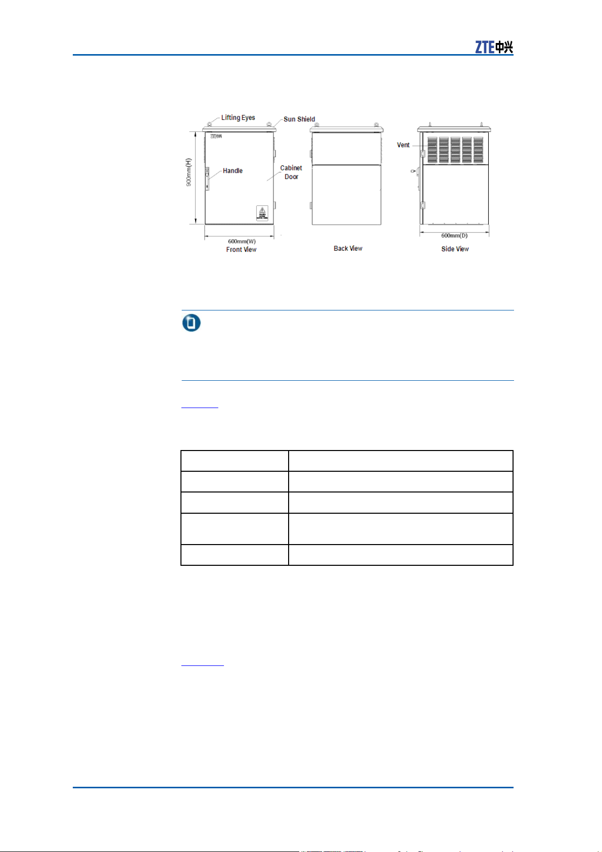
Figure 1 shows the baseband power cabinet outer structure.
Confidential and Proprietary Information of ZTE CORPORATION 1
Page 10
ZXSDR BS8900 Hardware Manual
FIGURE 1 BASEBAND POWER CABINET OUTER
S
TRUCTURE
– Cabinet dimension: 900 mm× 600
mm× 600 mm (height × width ×
depth)
Note:
It is common to place the baseband power cabinet on a storage
battery cabinet or an RF cabinet, in which case a sun shield is
needed but the base is not necessary.
Table 1 describes the components outer the baseband power cab-
inet.
TABLE 1 BASEBAND POWER CABINET OUTER COMPONENTS
Component
Lifting Eyes
Sun Shield
Handle
Vent
Description
Used in cabinet installation or removal.
Prevents the equipments from sunshine.
Used to open and close the cabinet door.
Equipped with alarm lock.
Helps cabinet heat-dissipation.
D
ESCRIPTION
Baseband
Inner
Structure
Power Cabinet
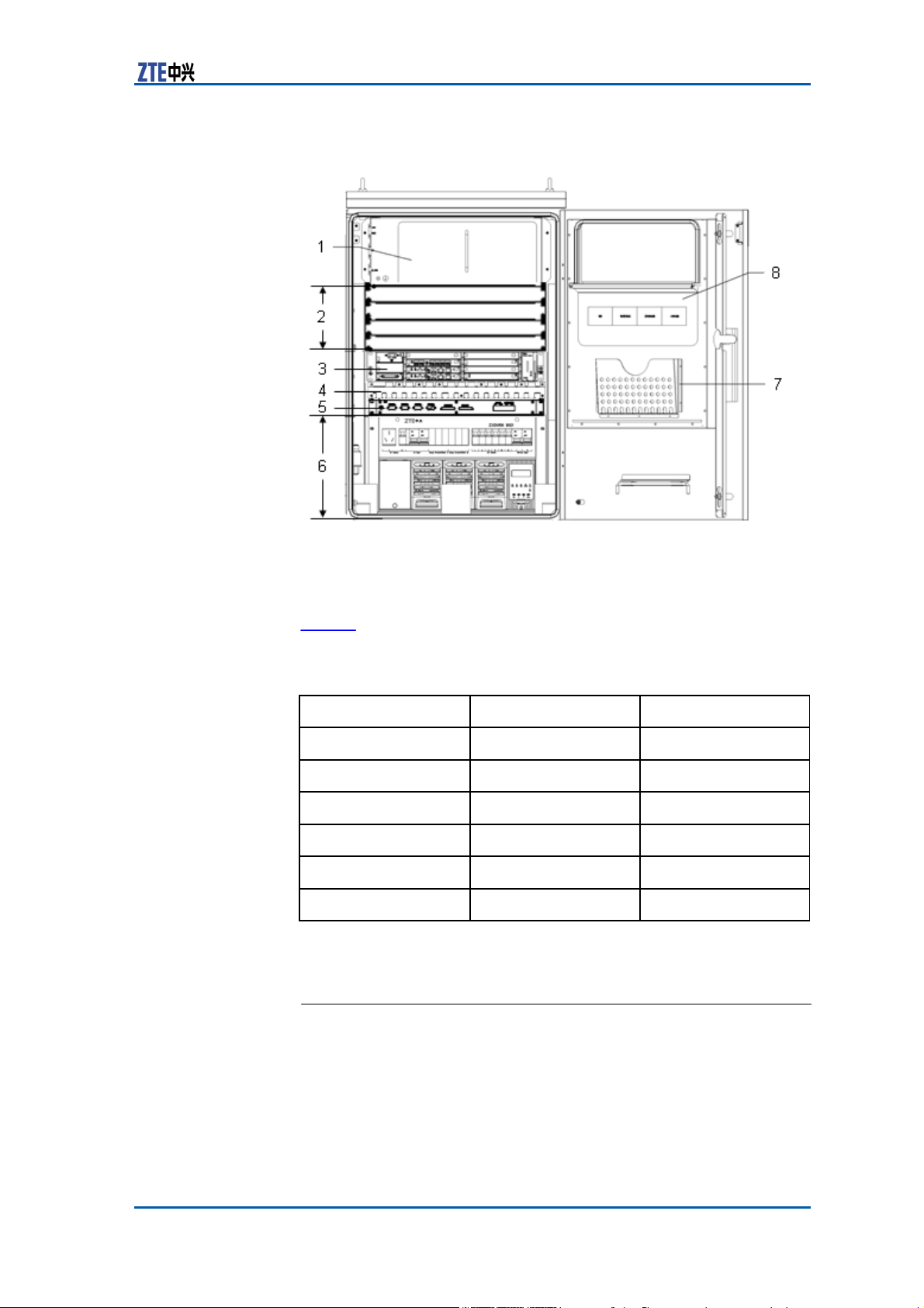
Figure 2 shows the baseband power cabinet inner structure.
2 Confidential and Proprietary Information of ZTE CORPORATION
Page 11
Chapter 1
Cabinet
FIGURE 2 BASEBAND POWER CABINET INNER
S
TRUCTURE
1. Heat exchanger
2. Reserved space
3. Baseband subrack
4. Cable tray
5. Lightning subrack
6. Power supply subrack
7. File box
8. Cabinet door
Table 2
describes
the configuration inside the
baseband
power cab-
inet.
Unit
Heat exchanger
Transmission subrack
Baseband subrack
Cable tray
Lightning subrack
Power supply subrack
– 1 U = 4.44 cm
Height
4 U
4 U reserved
2 U
1 U
1 U
6 U
TABLE 2 BASEBAND POWER CABINET INNER STRUCTURE
D
ESCRIPTION
Configuration
Compulsory
Optional
Compulsory
Optional
Optional
Compulsory
Heat
Exchanger
The heat exchanger has been installed inside baseband power cabinet before equipment consignment.
Judging from the feedback indices from temperature sensor, the
heat exchanger provides cooling or heating function to keep a stable temperature inside the cabinet and ensure the normal operation of equipments.
Confidential and Proprietary Information of ZTE CORPORATION 3
Page 12
ZXSDR BS8900 Hardware Manual
The heat exchanger consists of extracting core, heater, external
ventilation fan, internal ventilation fan and control panel. Two air
channels (inner and outer) are set to implement air convection.
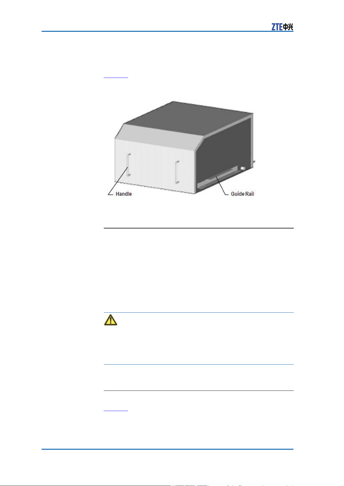
Figure 3 shows the heat exchanger structure.
FIGURE 3 HEAT
E
XCHANGER
STRUCTURE
Transmission
Transmission equipment is an optional configuration. The baseband power cabinet reserves a space of 19" wide and 4 U high for
its installation.
The transmission equipment adopts - 48 V DC supply with 200 W
power consumption.
The transmission equipment completes transmission signals conversion. ZXSDR BS8900 supports various types of transmis- sion
equipments, such as SDH, microwave, PDH optical transmis- sion
and HDSL.
Equipment (Optional)
Caution:
The transmission equipment demands a relatively small working
temperature range. Pay attention to the temperature in local environment for inside transmission equipment configuration since it
will decrease the BBU working temperature range.
Baseband
Subrack
4 Confidential and Proprietary Information of ZTE CORPORATION
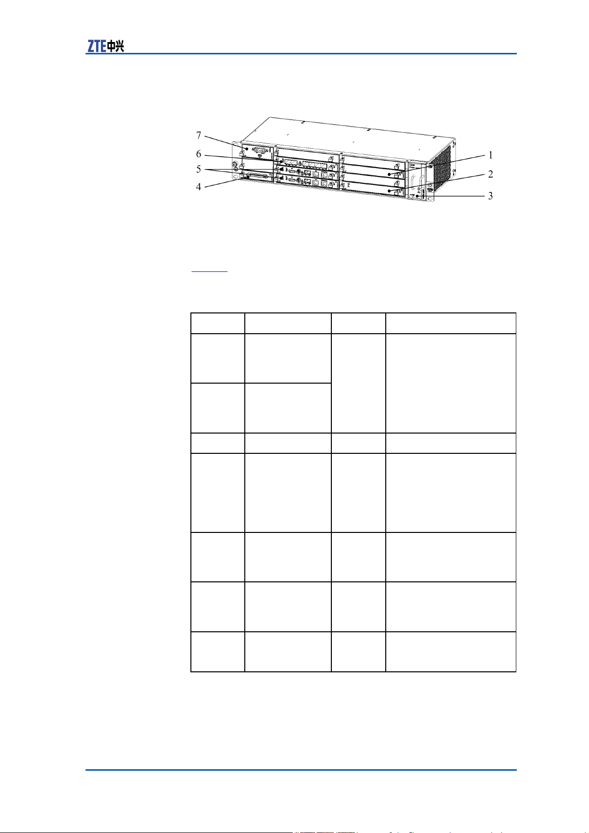
Figure 4 shows the ZXSDR BS8900 baseband subrack.
Page 13
Chapter 1
Cabinet
FIGURE 4 BASEBAND
S
UBRACK
1. CHV
2. CHD
3. FA
4. SA
5. CC
6. FS
7. PM
Table 3 describes the modules configured in the baseband subrack
slots.
Module Meaning
CHV
Channel
Quantity
1~4
Processing
TABLE 3 BASEBAND SUBRACK MODULES
Module
(1x
service)
CHD
Channel
D
ESCRIPTION
Description
A single module can
support 6 CS, Their
amounts are determined
by service demands.
Processing
Module
(DO
service)
FA
SA
Fan Array Module
Site Alarm
Module
1
1
—
Supports 8 E1/T1
interfaces, 8 dry
contacts (6 outputs
and 2 two-ways), 1
expanded RS232/RS485
communication interface
and fan monitor.
CC
Control
Module
and Clock
1~2
Supports 1+1
active/standby mode.
Both are configured only
upon specific request.
FS
Network Switch
Module
1~2
1 module is configured
as default. Supports load
sharing. Not support
active/standby mode.
PM
Power Module
1~2
1 module is configured as
default. 2 are configured
upon
specific
request.
Confidential and Proprietary Information of ZTE CORPORATION 5
Page 14
ZXSDR BS8900 Hardware Manual
Cable
Tray
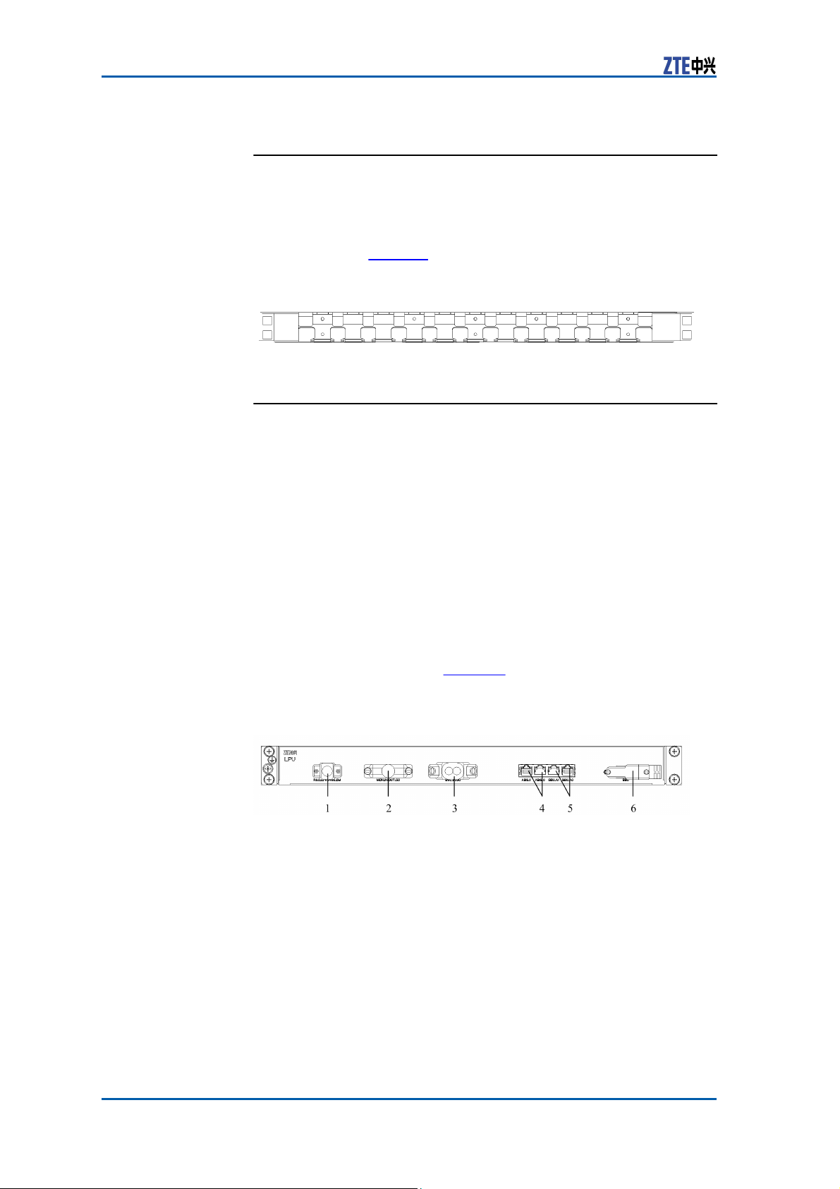
The cable tray locates in the baseband power cabinet and takes
up a 1 U high space.
The cable tray is used for cable wiring, management, supporting
and protection. Figure 5 shows its structure.
FIGURE 5 CABLE
T
RAY
STRUCTURE
Lightning
Subrack
The lightning subrack prevents the external RS232/RS485, dry
contact, E1/T1 and FE/GE interfaces of ZXSDR BS8900 out- door
transmission equipment from lightning and avoids damages to
the equipment caused by lightning induction and static electricity.
The lightning subrack fulfills the following functions:
�
Supports lightning protection of 8 dry contacts.
�
Supports lightning protection of one RS232 channel and one
RS485 channel.
�
Supports lightning protection of 8 E1 channels.
�
Supports lightning protection of 2 FE/GE electrical interfaces.
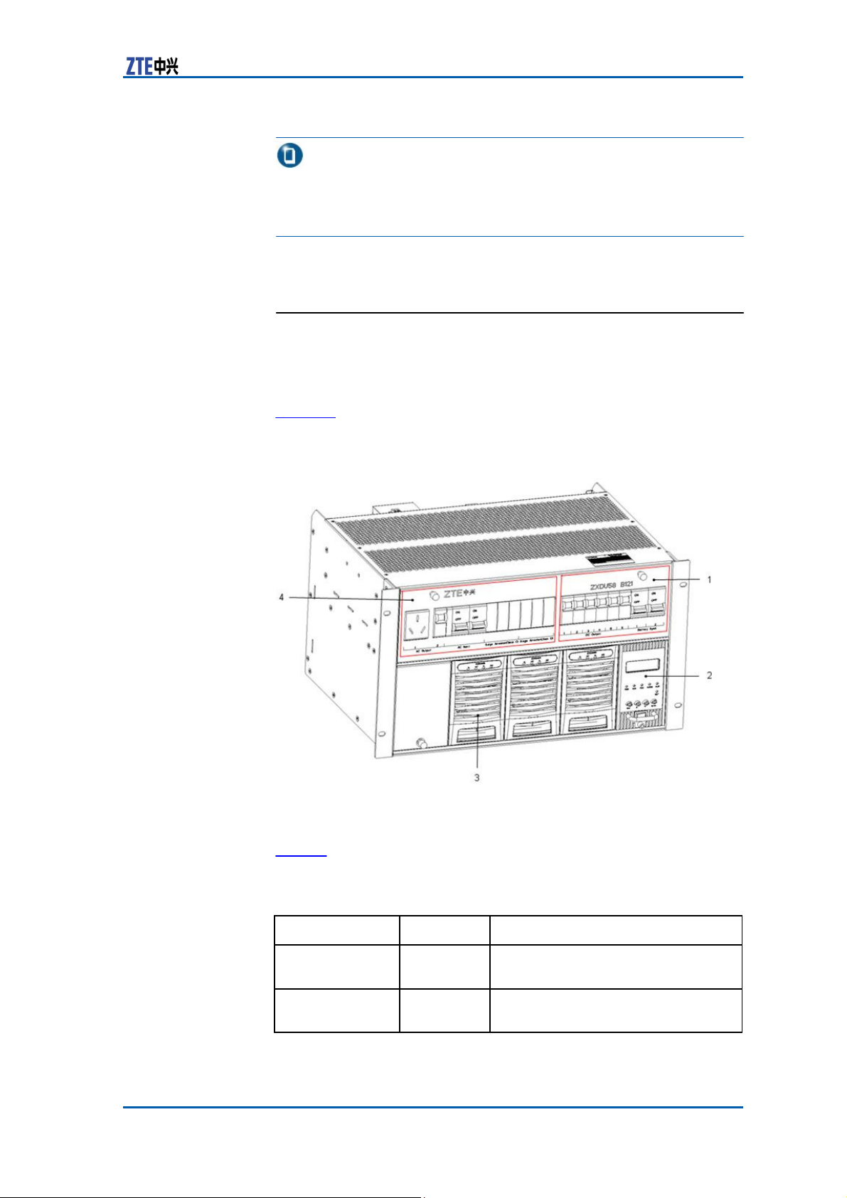
The lightning subrack locates in the baseband power cabinet, an
option for configuration. Figure 6 shows the lightning subrack
panel.
FIGURE 6 LIGHTNING
S
UBRACK
PANEL
1. RS232/RS485_EM
2. MON_IN/OUT_GO
3. BSC_E1_GO
4. ABIS_1/ABIS_0
5. BBU_A1/BBU_A0
6. BBU
6 Confidential and Proprietary Information of ZTE CORPORATION
Page 15
Chapter 1
Cabinet
Note:
The lightning subrack configuration is unnecessary when external
dry contact and external monitor are not required for GE optical
access to Abis interface.
Power
Supply Subrack
Composed
of AC
distribution
unit, DC
distribution
unit, rectifier and
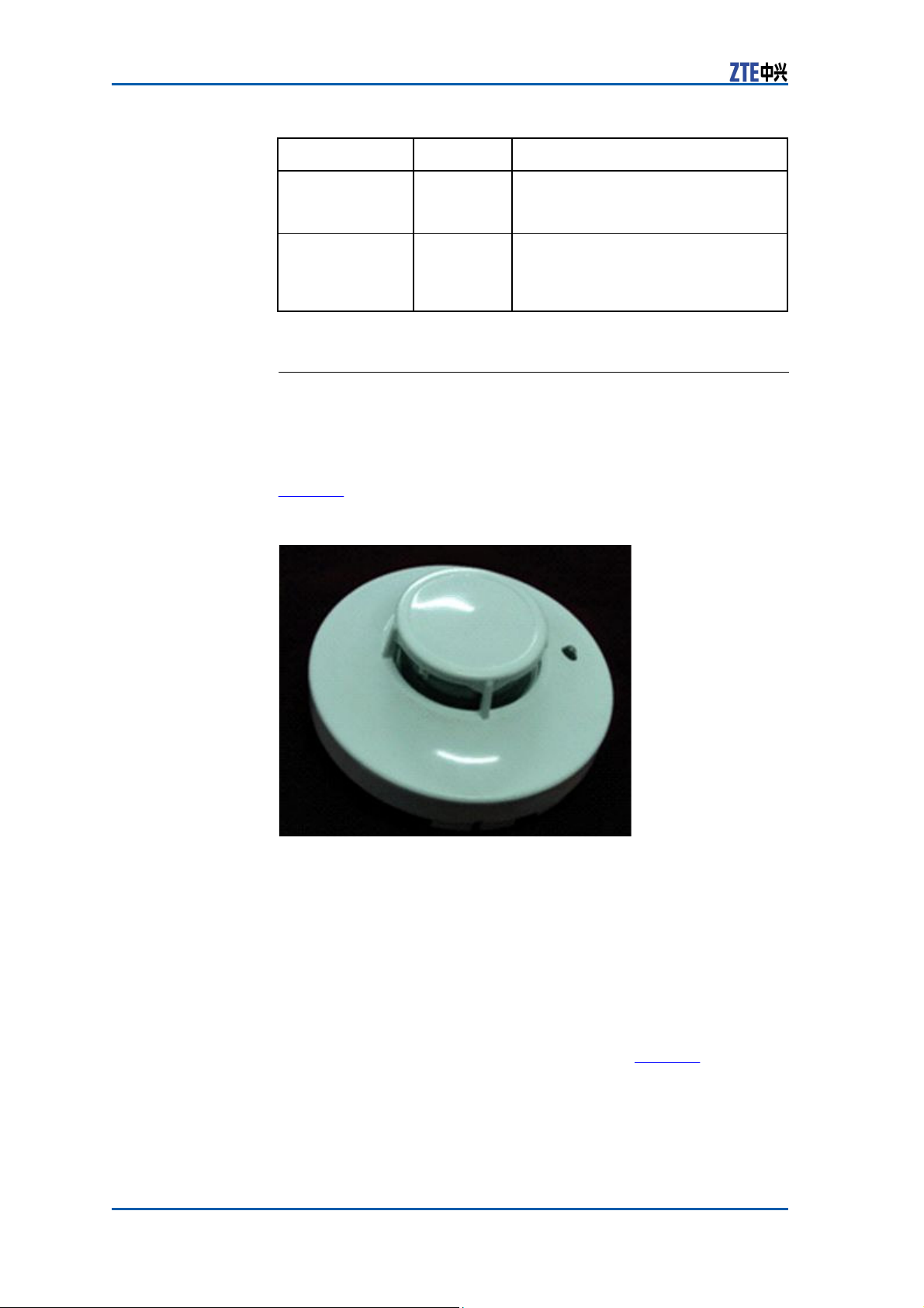
monitoring unit, the power supply subrack adopts a standard 19
inch structure with a 6 U height.
Figure 7 shows the structure of power supply subrack.
FIGURE 7 POWER SUPPLY
S
TRUCTURE
S
UBRACK
1. DC distribution unit
2. Monitoring unit
3. Rectifier
4. AC distribution unit
Table 4 lists the description of each composition unit of power sup-
ply subrack.
TABLE 4 POWER SUPPLY SUBRACK COMPOSITION UNIT
Unit
AC
distribution
unit
DC
distribution
unit
Quantity Description
1
1
Provides 2 sets of
standard
Provides overload protection for DC
output branch and battery branch.
configuration.
D
ESCRIPTION
standby outputs
in
Confidential and Proprietary Information of ZTE CORPORATION 7
Page 16
ZXSDR BS8900 Hardware Manual
Unit
Rectifier
Monitoring unit 1
Quantity Description
<=4
Adopts drawer structure with AC
single-phase 220 V input and DC -48
V/30 A output.
Adopts drawer structure. In charge
of integral
distribution
storage battery.
management of
unit, rectifier
module and
power
Smog
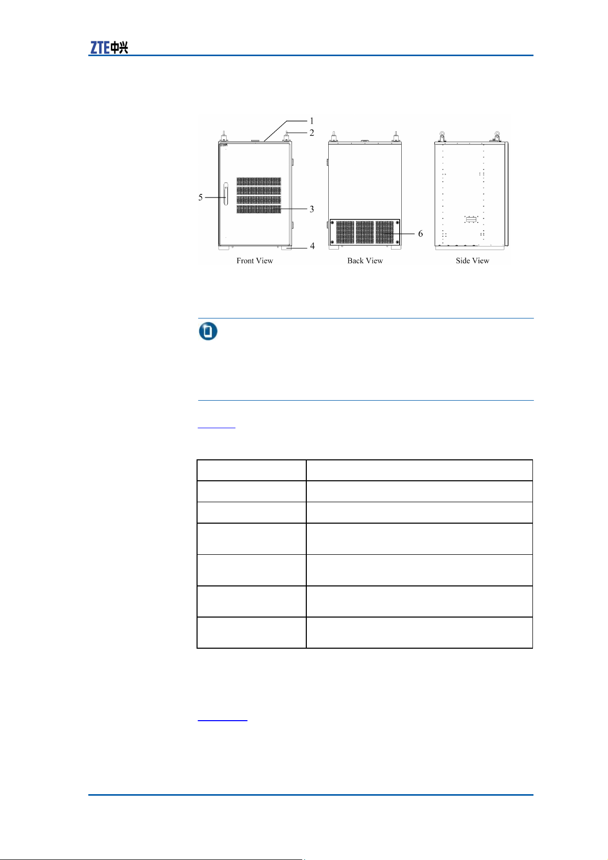
Sensor
The smog sensor lies in the left top corner of the RF cabinet for
detection of smog inside the cabinet.
The smog sensor is 104 mm in diameter and 47 mm in depth.
Figure 8 shows the structure of the smog sensor.
FIGURE 8 SMOG
S
ENSOR
STRUCTURE
The smog sensor with a ±12 V DC supply is connected to the smog
sensor interface on the panel of FCE that manages the smog alarm
and report.
RF
Cabinet Outer Structure
RF cabinet outer structure consists of the cabinet proper, cabinet
door, sun shield and the base, as is shown in Figure 9.
The cabinet dimension is 850 mm × 600 mm × 600 mm (height
× width × depth).
8 Confidential and Proprietary Information of ZTE CORPORATION
Page 17
Chapter 1
Cabinet
FIGURE 9 RF CABINET OUTER
S
TRUCTURE
1. Sun shield
2. Lifting eye
3. Heat-dissipation window
4. Base
5. Handle
6. Rear cover plate
Note:
Both the sun shield and base are required when the RF cabinet is
installed alone. When the cabinets are installed in heap, the sun
shield is needed for RF cabinet in the upper layer and teh base is
needed for RF cabinet in the lower layer.
Table 5 lists the description of RF cabinet outer components.
TABLE 5 RF CABINET OUTER COMPONENTS
Component
Sun shield
Lifting eye
Heat-dissipation
window
Base
Handle
Rear cover plate
Description
Prevents direct sun shine.
Used during cabinet installation and removal.
Helps cabinet heat-dissipation.
Used for cabinet fixation. Provides guard
against theft.
Used to open and close the cabinet door.
Equipped with alarm lock against theft.
Able to be disassembled and convenient for
cable connection.
D
ESCRIPTION
RF
Cabinet Inner Structure
Figure 10 shows the RF cabinet inner structure.
Confidential and Proprietary Information of ZTE CORPORATION 9
Page 18
ZXSDR BS8900 Hardware Manual
FIGURE 10 RF CABINET INNER
S
TRUCTURE
1. Fan subrack
2. Power distribution subrack
3. RF subrack
4. Base
5. Reserved for lightning filter
6. Air intake vent
7. Sun shield
10 Confidential and Proprietary Information of ZTE CORPORATION
Page 19
Chapter 1
Cabinet
Table 6 describes the inner configuration of RF cabinet.
Unit
Fan subrack
Power distribution subrack
RF subrack
Lightning Filter
Sun shield
Base
Configuration
Compulsory
Compulsory
Compulsory
Optional
Optional
Optional
TABLE 6 RF CABINET INNER CONFIGURATION
D
ESCRIPTION
Note:
The RF cabinet should be equipped with both sun shield and base
when placed alone. If installed in heap with other cabinet, it needs
sun shield for upper layer and base for lower layer.
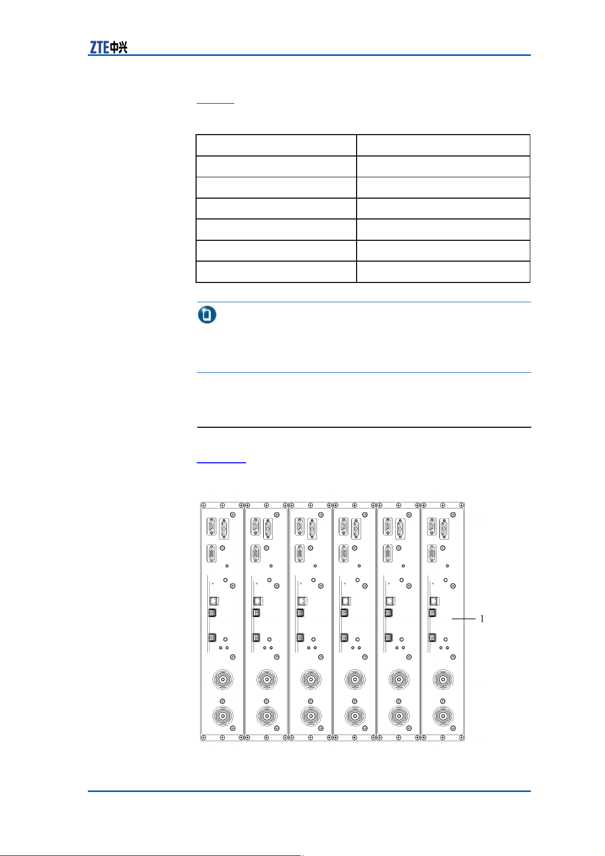
RF Subrack
Figure 11 illustrates the ZXSDR BS8900 RF subrack.
FIGURE 11 RF
S
UBRACK
1. RSU
Confidential and Proprietary Information of ZTE CORPORATION 11
Page 20
ZXSDR BS8900 Hardware Manual
Table 7 describes the module configured in RF subrack slots.
TABLE 7 RF SUBRACK MODULE
Module Meaning
RSU
Radio System
Unit
D
ESCRIPTION
Quantity
1~6
Description
A single RSU supports 4
carriers. RSU number is the
same with sector number if
the carrier number <=4 and
twice the sector number if 4
carrier
number <=6.
<
Lightning
Filter (Optional)
The lightning filter locates in the RF cabinet below RSU, an option
configuration.
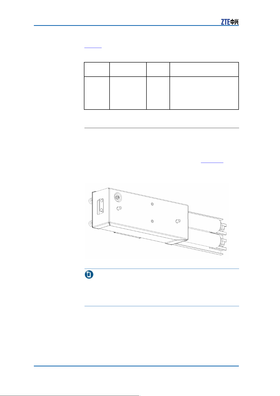
The lightning filter consists of 2 DC lightning protection units
(LPUs), 1 air break switch (ABS) and 2 DC filters. Figure 12 shows
its structure.
FIGURE 12 LIGHTNING
F
ILTER
STRUCTURE
Note:
1. Lightning filter needs to be configured when one RF cabinet is
installed alone or with a storage battery cabinet in heap or with
another RF cabinet in heap.
2. Lightning filter is unnecessary when one RF cabinet is installed
12 Confidential and Proprietary Information of ZTE CORPORATION
with a baseband power cabinet in heap.
Page 21
Chapter 1
Cabinet
Storage
Battery Cabinet
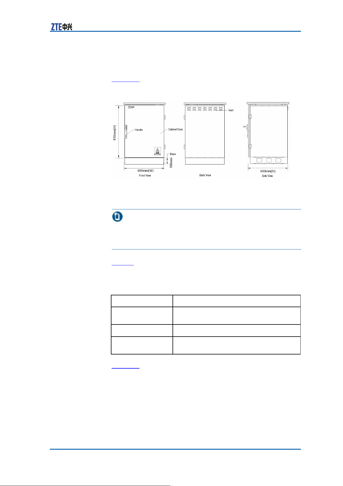
Outer Structure Figure 13 shows the storage battery cabinet outer structure.
FIGURE 13 STORAGE BATTERY CABINET OUTER
S
TRUCTURE
– Cabinet dimension: 850 mm× 600
mm× 600 mm (height × width ×
depth)
Note:
It is common to place the storage battery cabinet under a baseband power cabinet or an RF cabinet, in which case the base needs
to be installed but the sun shield is unnecessary.
Table 8 describes the components of the storage battery outer
structure.
TABLE 8 STORAGE BATTERY CABINET OUTER STRUCTURE
D
ESCRIPTION
Component
Handle
Vent
Base
Description
Used to open and close cabinet door. Equipped
with alarm lock.
helps cabinet heat-dissipation.
Used to fix the cabinet with alarm system
against theft.
C
OMPONENTS
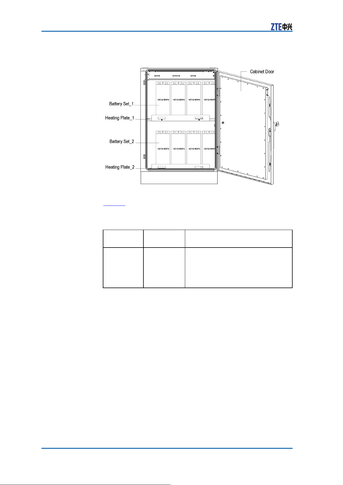
Inner Structure Figure 14 shows the storage battery cabinet inner structure.
Confidential and Proprietary Information of ZTE CORPORATION 13
Page 22
ZXSDR BS8900 Hardware Manual
FIGURE 14 STORAGE BATTERY CABINET INNER
S
TRUCTURE
Table 9 describes the inner configuration of the storage battery
cabinet.
TABLE 9 STORAGE BATTERY CABINET INNER CONFIGURATION
Unit
Storage
Battery Set
Configuration
Compulsory 1~2 sets, configured according to
Description
actual conditions. A single cabinet
supports a maximum capacity of 300
Ah with each set of 150
storage battery cabinet is needed for
more demands.
14 Confidential and Proprietary Information of ZTE CORPORATION
D
ESCRIPTION
Ah. Extra
Page 23

C
h a p t e r 2
Modules
Table of Contents
BBU Modules ....................................................................15
RRU Modules .................................................................... 34
BBU
Control
Modules
and Clock Module (CC)
Function CC module provides the following
�
Active/standby switchover
�
GPS system clock and RF reference clock
�
Abis interface function
�
Provision of the exchange plane for signaling stream and media
stream to implement GE Ethernet exchange function
�
One USB interface
�
Subrack management
�
Baseband modulation and demodulation
�
Provision of external clock extension interface (IEEE1588) and
communication extension interface (through the local mainte-
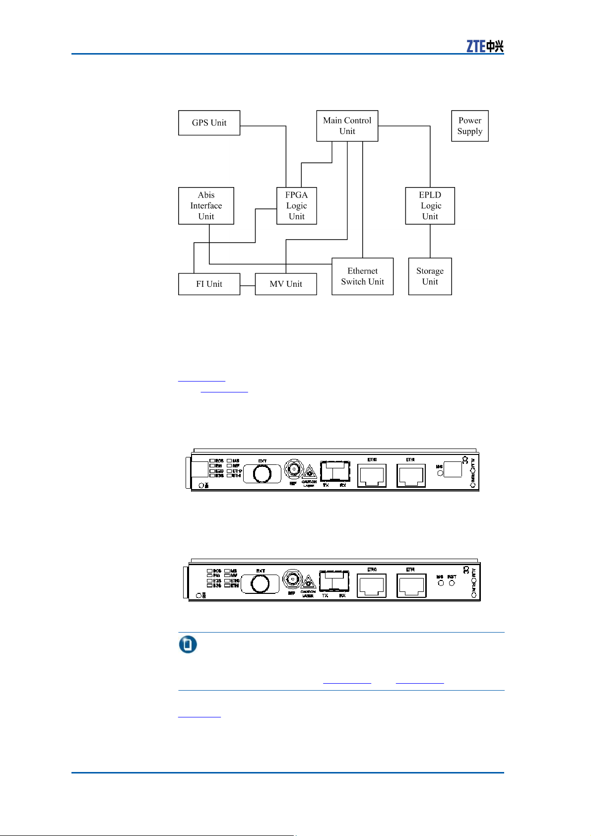
Principle The CC module comprises main control unit, GPS unit, power sup-
nance interface).
ply unit, storage unit, Abis interface unit, FI unit, MV unit, Ethernet
exchange unit, FPGA logic unit and EPLD logic unit.
Figure 15 illustrates the principle of the CC module.
functions:
Confidential and Proprietary Information of ZTE CORPORATION 15
Page 24
ZXSDR BS8900 Hardware Manual
FIGURE 15 CC MODULE
P
RINCIPLE
Dimension The dimensions of CC module in mm are: 148.8 (H) x 19.0 (W) x
181.5 (D).
The dimensions of CC module in inches are: 5 14/16 (H) x 12/16
Panel Figure 16 shows the appearance of the CC module panel with han-
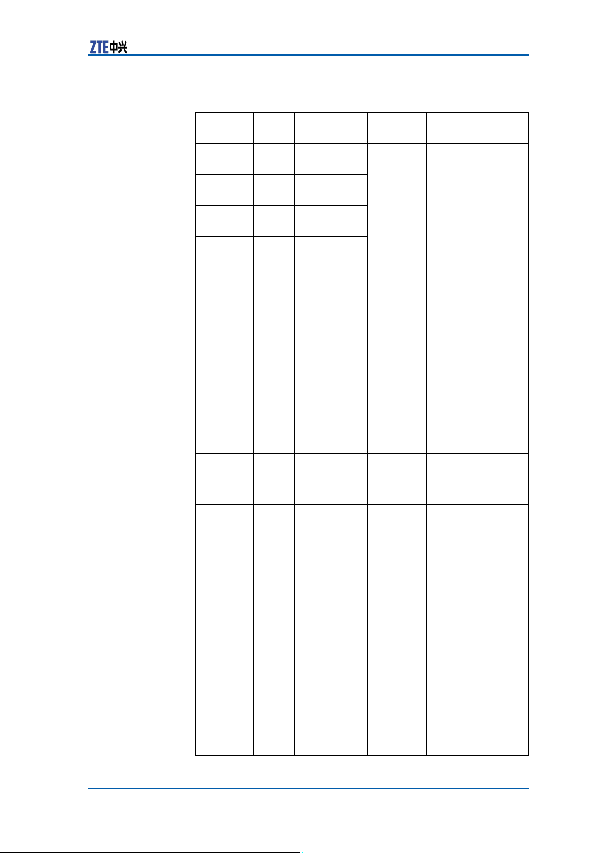
(W) x 7 2/16 (D)
dle. Figure 17 shows the appearance of the CC module panel with-
out handle.
FIGURE 16 CC MODULE PANEL (WITH
H
ANDLE
)
FIGURE 17 CC MODULE PANEL (WITHOUT
H
ANDLE
)
Note:
Some buttons will be covered if the CC module panel is equipped
with handle, as illustrated in Figure 16 and Figure 17.
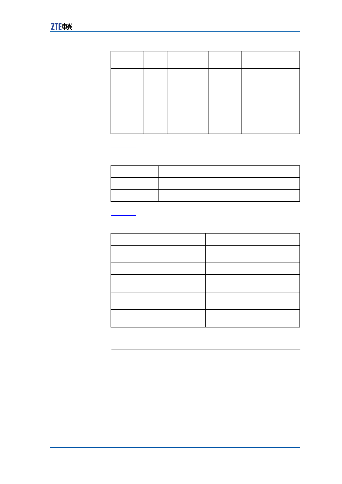
Indicator Table 10 describes the indicators on the CC module panel.
16 Confidential and Proprietary Information of ZTE CORPORATION
Page 25
Chapter 2
Modules
Indicator
Color Meaning
Name
TABLE 10 CC MODULE PANEL INDICATOR
E0S
Green
Indicator of
E1 link 1-4
E1S
Green
Indicator of
D
ESCRIPTION
Flash
Status
Flash frequency:
8Hz
E1 link 5-8
E2S
Green
Indicator of
E1 link 9-12
E3S
Green
Indicator of
E1 link 13-16
MS
Green
Ac-
No flash
tive/standby
indicator
REF
Green GPS antenna
indicator
Six flash
types
Description
At most 4 flashes
per second, and on
for 0.125 seconds
and off for 0.125
seconds.
The first second:
One flash means
that link 0 is normal.
Off when the link is
unavailable.
The third second:
Two flashes
the
first link is
mean
normal. Off
when the
link is
unavailable.
The fifth second:
Three flashes mean
the second link
is normal. Off
when the link is
unavailable.
The seventh
second: Four
flashes mean the
third link is normal.
Off when the link is
unavailable.
Recycle again per 8
seconds.
On refers to
the
active board
Off refers to
the
standby board.
On when the
antenna feeder
is normal.
Off when the
antenna feeder
and the satellite are
being initialized.
Slow flash: On for
1.5 seconds and
off for 1.5 seconds
when
the
antenna
feeder is broken
Quick flash: On for
0.3 seconds and off
for
0.3 seconds
when the antenna
feeder is normal but
can
not
search the
satellite.
Slower flash: On
for 2.5 seconds and
off for 2.5 seconds
when the antenna is
short—circuited.
Confidential and Proprietary Information of ZTE CORPORATION 17
Page 26

ZXSDR BS8900 Hardware Manual
Indicator
Name
Color Meaning
ETH0
ETH1
ALM
RUN
18 Confidential and Proprietary Information of ZTE CORPORATION
Green
Green
Red
Green
Abis interface
link
status
indicator
ETH1
network port
link status
indicator
Alarm
Indicator
Running
Indicator
Flash
Status
No flash,
controlled
by PHY
No flash,
controlled
by PHY
Processor
Control
Six flash
types
Description
Quicker flash: On
for 70 ms and off
for 70 ms
when no
message is received
during initialization.
On when the Abis
interface physical
link is normal.
Off when the Abis
interface physical
link is broken.
On when the
ETH1 network port
physical link is
normal.
Off when the
ETH1 network port
physical link is
broken.
On when an alarm
occurs on the
module.
Off when no alarm
occurs on the
module.
On when the version
file begins to run to
request for the
logical address of
the module.
Slow flash: On for
1.5 seconds and off
for
1.5 seconds
when the module is
being powered on.
Normal flash: On
for 0.3 seconds and
off for 0.3 seconds
when the board
is under normal
operation.
Slow flash: On
for 2 seconds and
off for 2 seconds
when the board is
in active/standby
pre-changeover.
Slow flash: On
for 1
second and
off for 1 second
when
the
board is
in active/standby
changeover.
Fast flash: On
for 70 ms and off
for 70 ms when
communication
between CC
board and OMP
Page 27
Indicator
Color Meaning
Name
Flash
Status
Description
is interrupted, or
communication
between active and
standby CCs/FSs
is
interrupted, or
communication
between CH
CC is interrupted,
or communication
between FS and CC
is interrupted.
Button Table 11 describes the buttons on the panel of CC module.
Button
M/S
RST
Description
Active/standby switchover button
Reset button
TABLE 11 CC MODULE PANEL BUTTON
D
ESCRIPTION
Panel Interface Table 12 describes interfaces on the panel of CC module.
GPS
antenna
Interface Name
TABLE 12 CC MODULE PANEL INTERFACE
ETH0
D
ESCRIPTION
Description
GE/FE port connection between
BBU and BSC
ETH1
EXT
Debugging or local maintenance
Connecting the external receiver
(RS485, PP1S and 2M
REF
Connecting
externally
TX/RX
Connecting the optical interface
between BBU and BSC
Chapter 2
interfaces)
Modules
and
Channel
Processing Module (CH)
Function CH module performs the following functions:
�
The forward modulation and reverse demodulation of base-
band
�
CDMA key technologies, such as diversity technique, RAKE
receiving, softer-handoff and power control
�
Mixed insertion of CHV and CHD modules to support 1x and
EV-DO service.
Confidential and Proprietary Information of ZTE CORPORATION 19
Page 28
ZXSDR BS8900 Hardware Manual
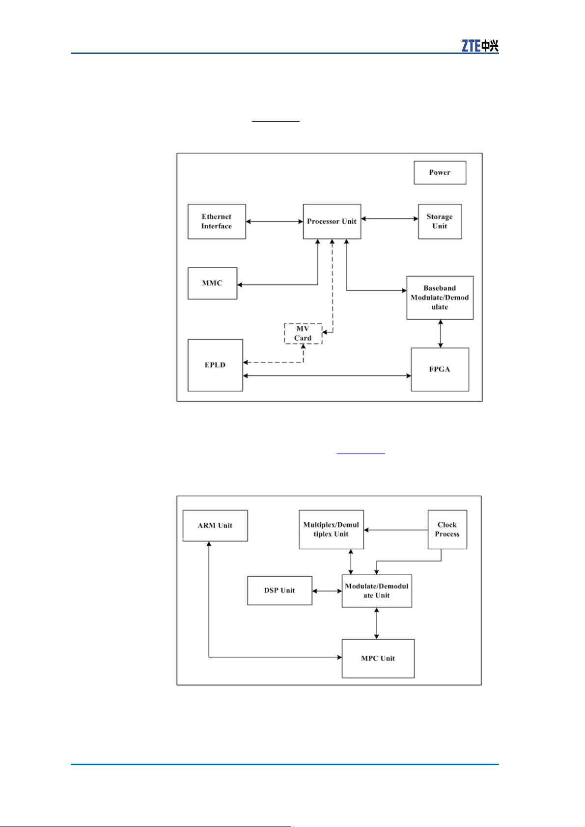
Principle CHV module consists of processing unit, baseband modulation and
demodulation unit, FPGA unit, EPLD logic unit, power,
and MMC unit. Figure 18 shows the principle of CHV module.
FIGURE 18 CHV
M
ODULE
PRINCIPLE
Ethernet
unit
CHD module consists of multiplexing and de-multiplexing unit,
clock processing unit, ARM unit, DSP unit, modulation and demodulation unit and MPC unit. Figure 19 shows the principle of
CHD module.
FIGURE 19 CHD
M
ODULE
PRINCIPLE
Measurement The dimensions of CH module in mm are: 148.8 (H) x 19.0 (W) x
181.5 (D).
20 Confidential and Proprietary Information of ZTE CORPORATION
Page 29
Chapter 2
Modules
The dimensions of CH module in inches are: 5 14/16 (H) x 12/16
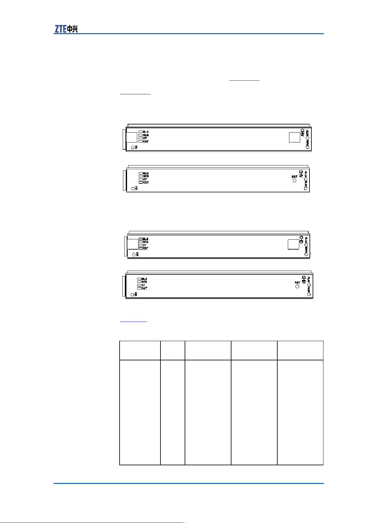
Panel CH is classified into CHV and CHD. Figure 20 shows the panel ap-
(W) x 7 2/16 (D).
pearance of CHV module with and without handle respectively.
Figure 21 shows the panel appearance of CHD module with and
without handle respectively.
FIGURE 20 CHV MODULE
P
ANEL
FIGURE 21 CHD MODULE
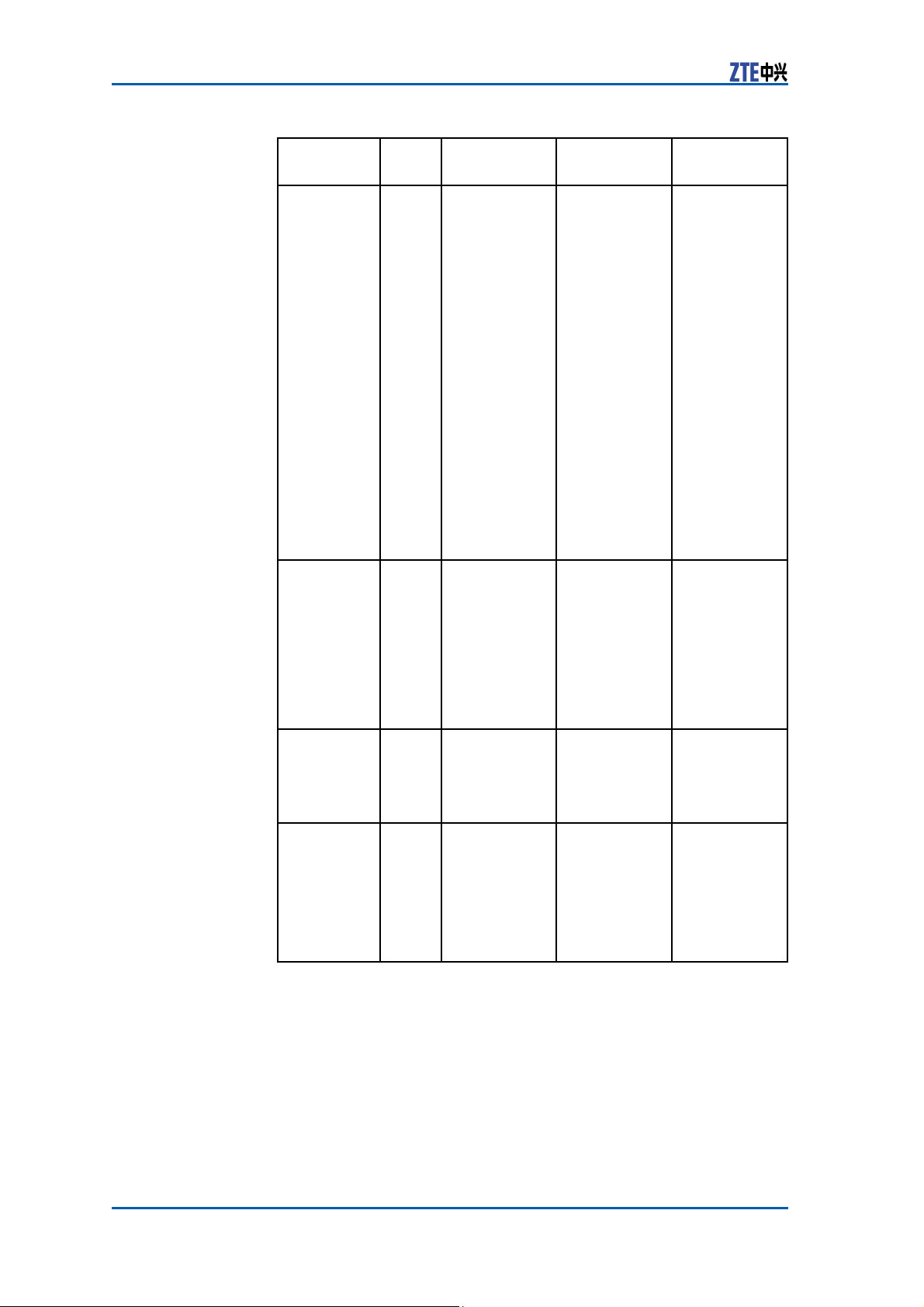
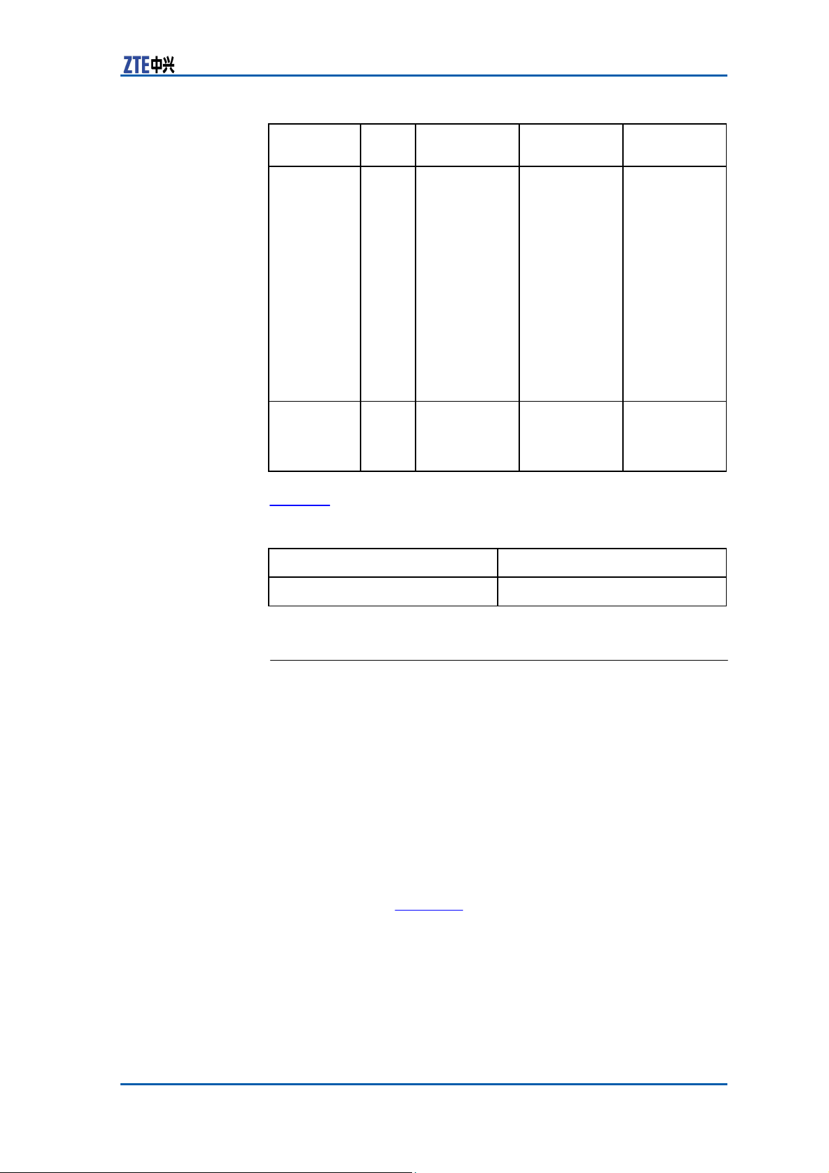
Indicator Table 13 describes the indicators on the panel of CH
TABLE 13 CH MODULE PANEL INDICATOR
Indicator
Color Meaning
Name
BLS
Green
Confidential and Proprietary Information of ZTE CORPORATION 21
P
ANEL
Baseband link
(forward/reverse) running status
indicator
module.
D
ESCRIPTION
Flash Status Description
The flash
frequency
is
8Hz; it
indicates
the SERDES
receiving
status and
the forward
baseband
signal failure
while FS0/FS1
board
connects to
CH board.
Ordinal flash
on time, the
maximum
flash for four
times per second, 0.125s
On and 0.125s
Off
The first second: one flash
means communication
with FS0 is
normal and
Off means
communica-
Page 30
ZXSDR BS8900 Hardware Manual
(50CHIP/10ms)
Indicator
Name
Color Meaning
SCS
ST
CST
22 Confidential and Proprietary Information of ZTE CORPORATION
Green System clock
running status
indicator
Green Reservation
Green Communica-
tion status
indicator between CPU
and MMC
Flash Status Description
tion is broken.
The forth second: two
flashes
mean
communication
with FS1
is normal
and
Off means
communication is broken.
Recycle
again
per 6 seconds.
If the
ward
for-
IO signal
check from
the channel
chip output is
wrong, it is
always
off.
If the 61.44M
clock or the
32CHIP clock
is wrong, it is
Three
statuses: On,
quick flash
and
Off.
always
On: the
system clock
running is
normal.
off.
Quick flash:
10ms wrong,
0.125s On and
0.125s Off.
Off:
50CHIP
wrong.
Controlled by
-
CPU, EPLD
transparent
transmission
mode
Controlled by
CPU, EPLD
transparent
transmission
mode
On: normal
communication between
CPU
and MMC
Off: failed
communication between
CPU and MMC.
Page 31
Chapter 2
Modules
Indicator
Name
RUN
ALM
Color Meaning
Green
Running
Indicator
Red
Alarm
Indicator
Flash Status Description
Four statuses:
5Hz flash, 1Hz
flash, On and
Off.
5 Hz flash:
the
board is
in power-up
procedure.
1 Hz flash:
the board
is normally
running.
On: the
version is
downloaded
successfully
and is being
started.
Off: the board
is abnormal.
Processor
Control
On:
the board
has alarm.
Off: the board
has no alarm.
Button Table 14 describes the button on the CH Panel.
TABLE 14 CH BUTTON
D
ESCRIPTION
Button Name
RST
Description
Reset
Fabric
Switch Module (FS)
Functions The FS module provides the following functions:
�
In forward direction, performs the baseband data multiplexing
and framing and then transmit them to the remote RRU.
�
In reverse direction, performs deframing and demultiplexing
for received RRU remote data and then transmit them to the
baseband processing unit.
�
Supports six remote baseband fiber interfaces.
�
The logic unit implements all the functions except for optical
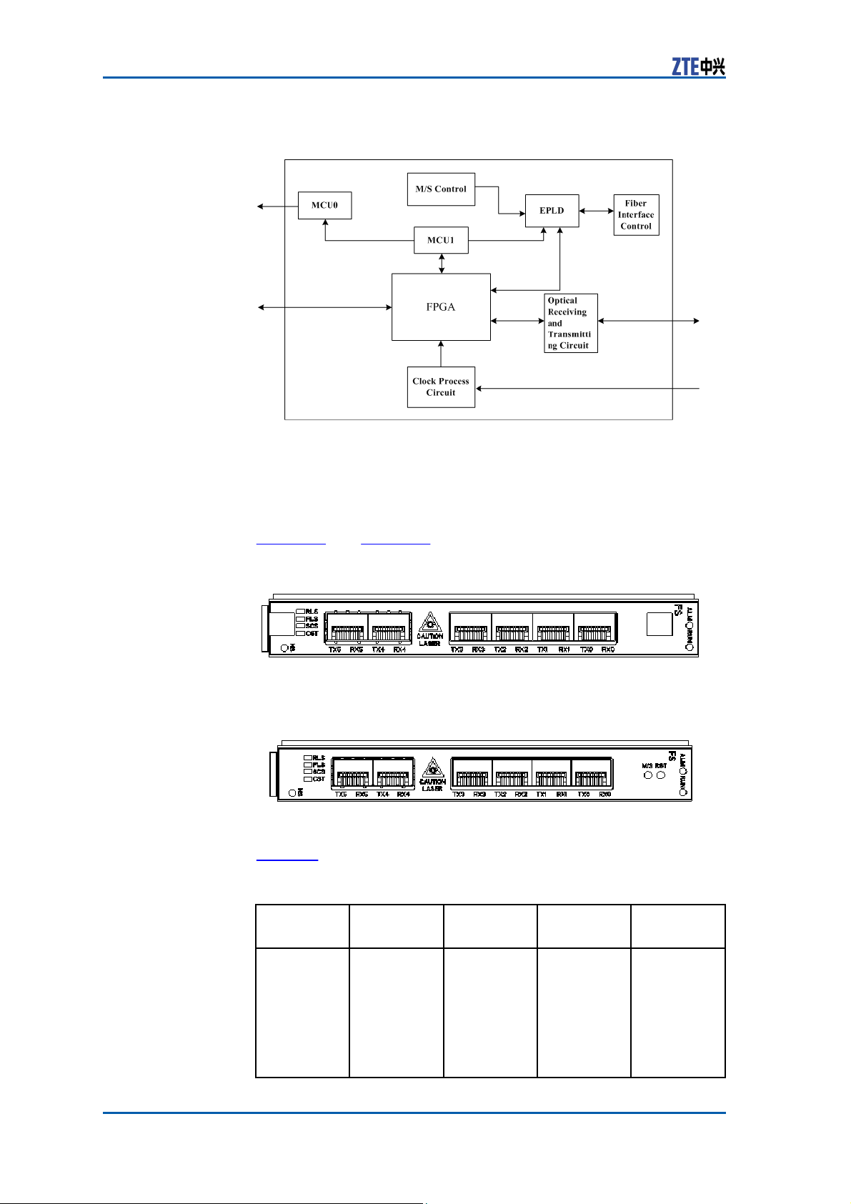
Principle The FS module comprises active/standby control unit, MCU0 unit,
interface processing.
MCU1 unit, EPLD logic, optical interface control unit, FPGA unit,
optical receiving and transmitting circuit and clock processing circuit, as shown in Figure 22.
Confidential and Proprietary Information of ZTE CORPORATION 23
Page 32
ZXSDR BS8900 Hardware Manual
FIGURE 22 FS MODULE
P
RINCIPLE
Measurement The dimensions of FS module in mm are: 148.8 (H) x 19.0 (W) x
181.5 (D).
The dimensions of FS module in inches are: 5 14/16 (H) x 12/16
(W) x 7 2 /16 (D).
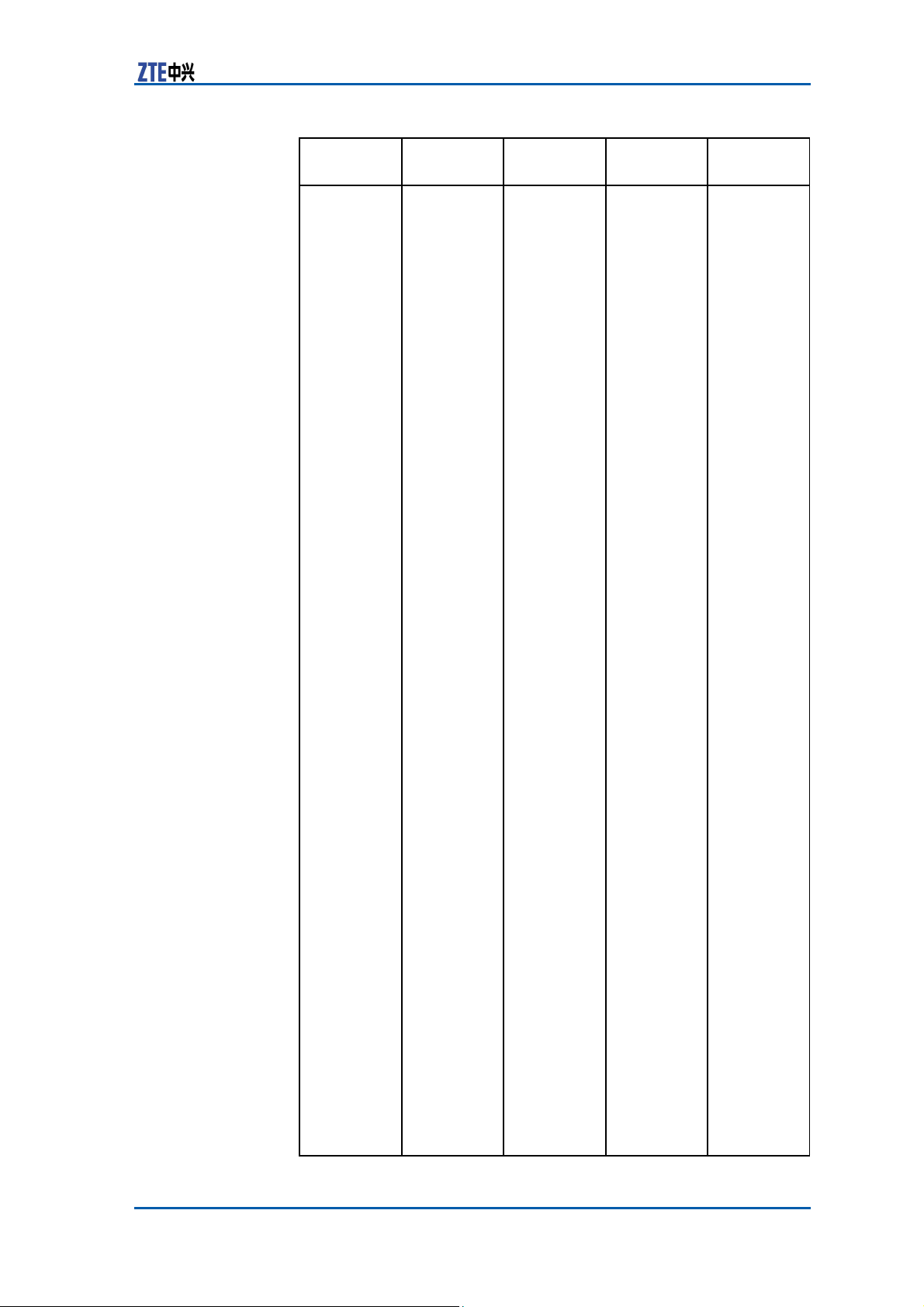
Panel Figure 23 and Figure 24 show the FS module
FIGURE 23 FS MODULE PANEL WITH
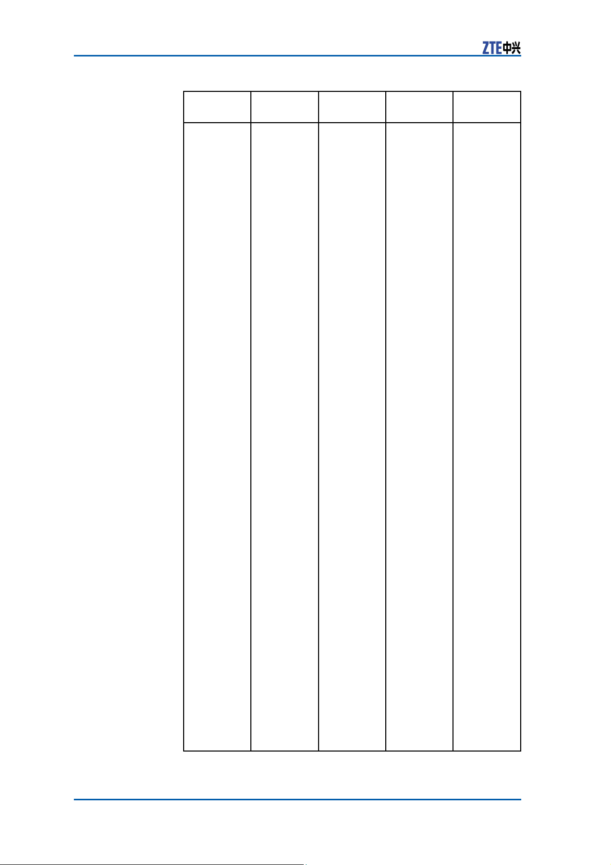
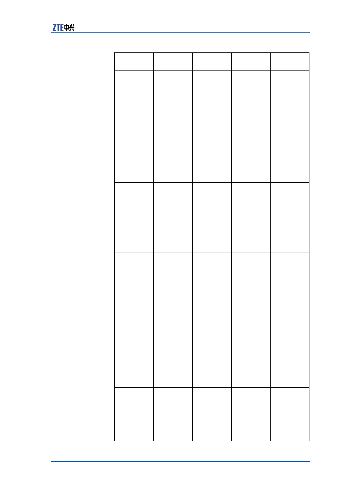
Indicator Table 15 describes the indicators on FS panel.
24 Confidential and Proprietary Information of ZTE CORPORATION
FIGURE 24 FS MODULE PANEL WITHOUT
TABLE 15 FS PANEL INDICATOR
Indicator Color
RLS
Green
D
Meaning Flash
Reverse
baseband
link running
status
indicator
H
ANDLE
H
ANDLE
ESCRIPTION
panel.
Status
Controlled
by
FPGA;
the
flash
frequency
is 8Hz;
it means
the
locking
status of
Description
At most
flashes
second.
for 0.125
seconds and
off for 0.125
seconds.
The first
four
per
On
Page 33
Chapter 2
Modules
Indicator Color
Meaning Flash
Status
the reverse
optical
interfaces
from all
fibers to FS.
Description
second:
One flash
means
0 is
Off
the link is
unavailable.
The forth
second:
Two flashes
mean the
1st link
is normal.
Off when
the link is
unavailable.
The seventh
second:
Three
flashes
mean the
2nd link
is normal.
Off when
the link is
unavailable.
The tenth
second:
Four
mean the
3rd link
is normal.
Off when
the link is
unavailable.
The
thirteenth
second:
five flashes
mean the
4th link is
normal
Off means
the 4th is
unavailable.
The
sixteenth
second:
Six flashes
mean the
5th link
is normal.
Off when
the
broken.
Recycle
again
18 seconds.
Off when
an error
occurs on
the 61.44M
clock.
link
normal.
when
flashes
and
5th is
per
Confidential and Proprietary Information of ZTE CORPORATION 25
Page 34
ZXSDR BS8900 Hardware Manual
Indicator Color
FLS
Green
Meaning Flash
Forward
baseband
link running
status
indicator
26 Confidential and Proprietary Information of ZTE CORPORATION
Status
Controlled
by
FPGA;
the
flash
frequency
is 8Hz;
it means
the data
receiving
status of
the forward
SERDES
from
all CH
modules to
FS.
Description
At most
flashes
second.
four
per
On
for 0.125
seconds and
off for 0.125
seconds.
The first
second:
One flash
means
0 is
Off
link
normal.
when
the link is
broken.
The forth
second:
Two flashes
mean the
1st link
is normal.
Off when
the
link is
broken.
The seventh
second:
Three
flashes
mean the
2nd link
is normal.
Off when
the
link is
broken.
The tenth
second:
Four
flashes
means the
3rd link
is normal.
Off when
the
link is
broken.
The
thirteenth
second:
Five flashes
means the
4th link
is normal.
Off when
the
link is
broken.
Recycle
again
per
15 seconds.
Off when
an error
occurs on
the 61.44M
clock.
Page 35
Chapter 2
Modules
Indicator Color
SCS
CST
RUN
ALM
Green
Green
Green
Red
Meaning Flash
Status
System
clock
running
status
indicator
FPGA
control
indicator
, three
status:
quick flash
and off.
Communication status indicator between
CPU and
MMC
Running
Indicator
Alarm
Indicator
Controlled
by CPU,
EPLD transparent
transmission
MMC control
indicator
MMC control
indicator
on,
Description
On when
the system
clock is
normal.
Quickly
blinks (on
for 0.125
seconds and
off for 0.125
seconds)
when a
10ms clock
failure
occurs.
Off when a
50CHIP
clock failure
occurs.
On when the
communication between CPU
and
MMC is
normal.
Off when
CPU fails to
communicate with
MMC.
Blinks in
5 Hz flash
when the
module is
being powered on.
Blinks in
1 Hz flash
when the
module runs
normally.
On when
the module is
starting the version after
downloading it successfully.
Off when
the module
is abnormal.
On when
an alarm
occurs on
the
module.
Off
when
no alarm
occurs on
the module.
Confidential and Proprietary Information of ZTE CORPORATION 27
Page 36
ZXSDR BS8900 Hardware Manual
Site
Alarm Module (SA)
Function SA module provides the following
�
Communication with CC through PMB-0 cable to implement CC
unit functions.
�
Nine fan rev control and monitoring.
�
Provision of one UART to communicate with the master control
board CC.
�
Extensible full-duplex RS232 and RS485 communication chan-
nel for connected-externally monitoring equipment.
�
Six dry contact inputs and two bidirectional dry contacts.
�
Temperature sensor monitoring interface for FA .
�
Eight E1/T1 interfaces and interface protection.
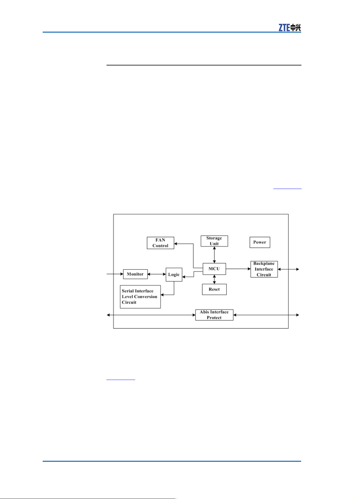
�
Principle The SA module comprises management unit, reset unit, monitor-
BDS_ID and ABIS_MODE configuration.
ing unit, E1/T1 interface protection unit and power unit. Figure 25
shows the SA module principle.
FIGURE 25 SA MODULE
P
RINCIPLE
functions.
Measurement The dimensions of SA module in mm are: 73.8 (H) x 19.0 (W) x
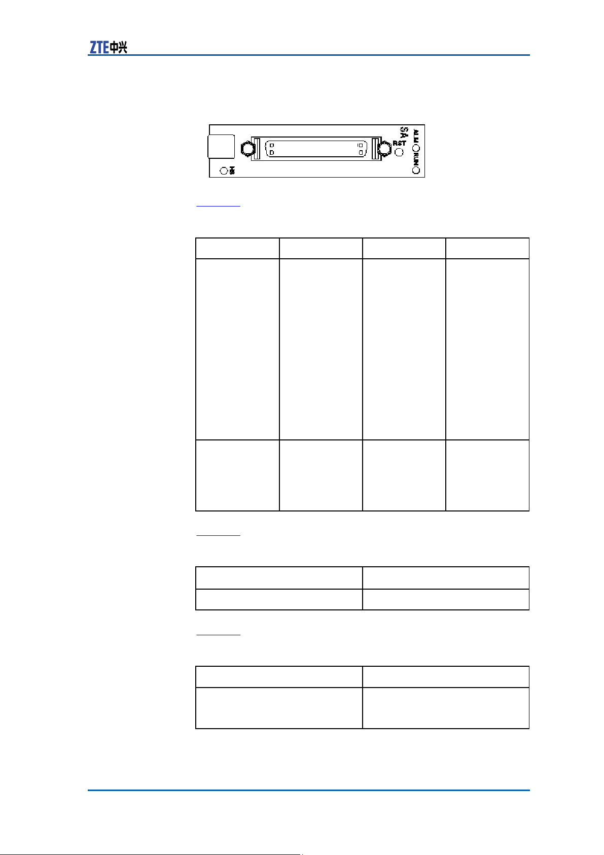
Panel Figure 26 shows the panel of SA
181.5 (D).
The dimensions of SA module in inches are: 2 14/16 (H) x 12/16
(W) x 7 12/16 (D).
28 Confidential and Proprietary Information of ZTE CORPORATION
module.
Page 37
Chapter 2
Modules
FIGURE 26 SA MODULE
P
ANEL
Indicator Table 16 describes the indicators on the panel of SA module.
Indicator
RUN
Color
Green
TABLE 16 SA PANEL INDICATOR
D
ESCRIPTION
Meaning
Running
Indicator
ALM
Red
Alarm Indicator
Button Table 17 describes the button on the panel of SA module.
TABLE 17 SA BUTTON
D
ESCRIPTION
Button
RST
Description
Reset button
Panel Interface Table 18 describes the panel interfaces on SA module.
Interface Name
TABLE 18 SA PANEL INTERFACE
Mon/Abis
D
ESCRIPTION
Description
Abis connection ,RS232 / RS485
monitoring and dry contact
monitoring
Confidential and Proprietary Information of ZTE CORPORATION 29
Description
Blinks in 5
Hz when the
module is
powered
being
on.
Blinks in 1
Hz
when the
module runs
normally.
On when the
module is
starting the
version after
downloading it
successfully.
Off when the
module is
abnormal.
On when an
alarm occurs on
the
module.
Off when no
alarm occurs on
the
module.
Page 38
ZXSDR BS8900 Hardware Manual
Fan
Array Module (FA)
Function FA provides the following
�
Fan control and air inlet temperature check
�
Fan control interface
�
Provision of a temperature sensor for FA module to check the
temperature of air inlet
�
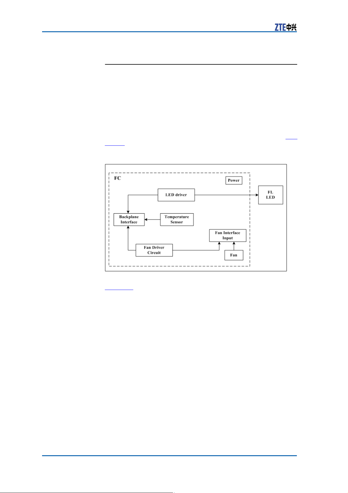
Principle The FA module comprises temperature sensor unit, fan drive unit,
Fan subrack LED status display.
LED drive, power supply, fan, backplane interface and FL unit. Fig-
ure 27 shows the principle of the FA module.
FIGURE 27 FA MODULE
functions:
P
RINCIPLE
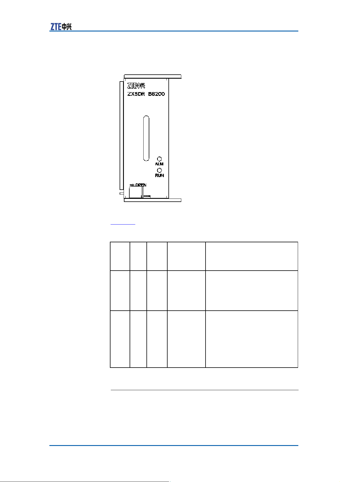
Panel Figure 28 shows the panel of the FA
30 Confidential and Proprietary Information of ZTE CORPORATION
module.
Page 39
-
Chapter 2
Modules
FIGURE 28 FA MODULE
P
ANEL
Indicator Table 19 describes the indicators on the panel of the FA module.
TABLE 19 FA PANEL INDICATOR
Indicator
RUN
ALM
Colo
Gree
Red
Mean
ing
Running
indicator
Alarm
indicator
Flash
Status
Flash
frequency:
on for 0.3
seconds and
off for
seconds
Flash
frequency:
on for 0.3
seconds and
off for
seconds
D
ESCRIPTION
0.3
0.3
Description
On when the FA is powered on
and not controlled by
Off when the FA is
Blinks (on for 0.3 seconds and off
for 0.3 seconds) when the FA is
controlled by SA.
On when the FA is powered on
and not controlled by SA (i.e., the
RUN indicator is on) or when a
fan failure
indicator
Off when the FA is
the RUN indicator blinks) or when
the FA is powered off (i.e., the
RUN indicator is off).
occurs (i.e.,
blinks).
SA.
powered off.
the RUN
normal (i.e.,
Power
Module (PM)
Function PM module performs the following
�
16 internal interfaces for +12 V load power
�
16 internal interfaces for +3.3 V management power
Confidential and Proprietary Information of ZTE CORPORATION 31
functions:
Page 40
ZXSDR BS8900 Hardware Manual
�
EMMC management
�
Input over-voltage and under-voltage measurement and pro-
�
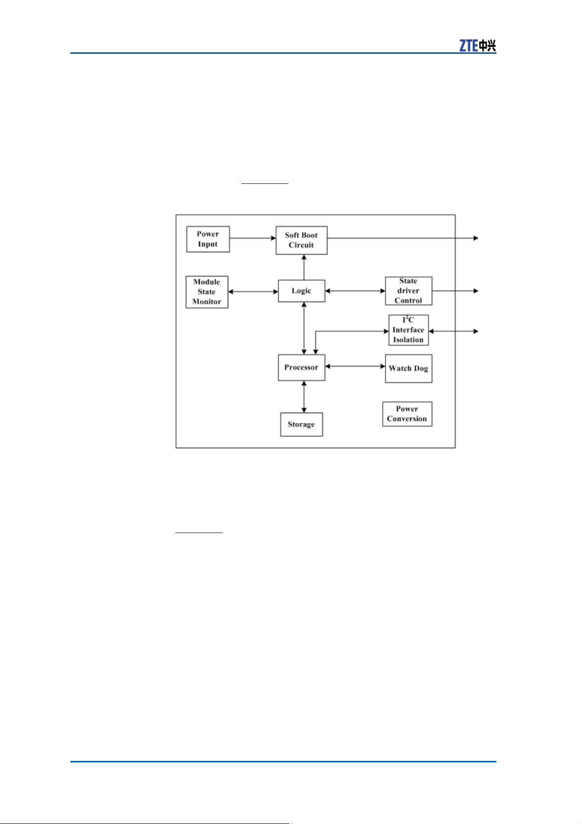
Principle The PM comprises power input unit, soft-startup circuit, status
Output over-current protection and load power management.
monitoring unit, logic unit, CPU, storage, status drive control circuit, I2C interface isolation unit, watchdog circuit and power conversion unit. Figure 29 shows the principle of the PM module.
FIGURE 29 PM MODULE
tection
P
RINCIPLE
Measurement The dimensions of PM module in mm are: 73.8 (H) x 29.0 ( W) x
181.5 (D)
The dimensions of PM module in inches are: 2 14/16 (H) x 1 2/16
( W) x 7 12/16 (D)
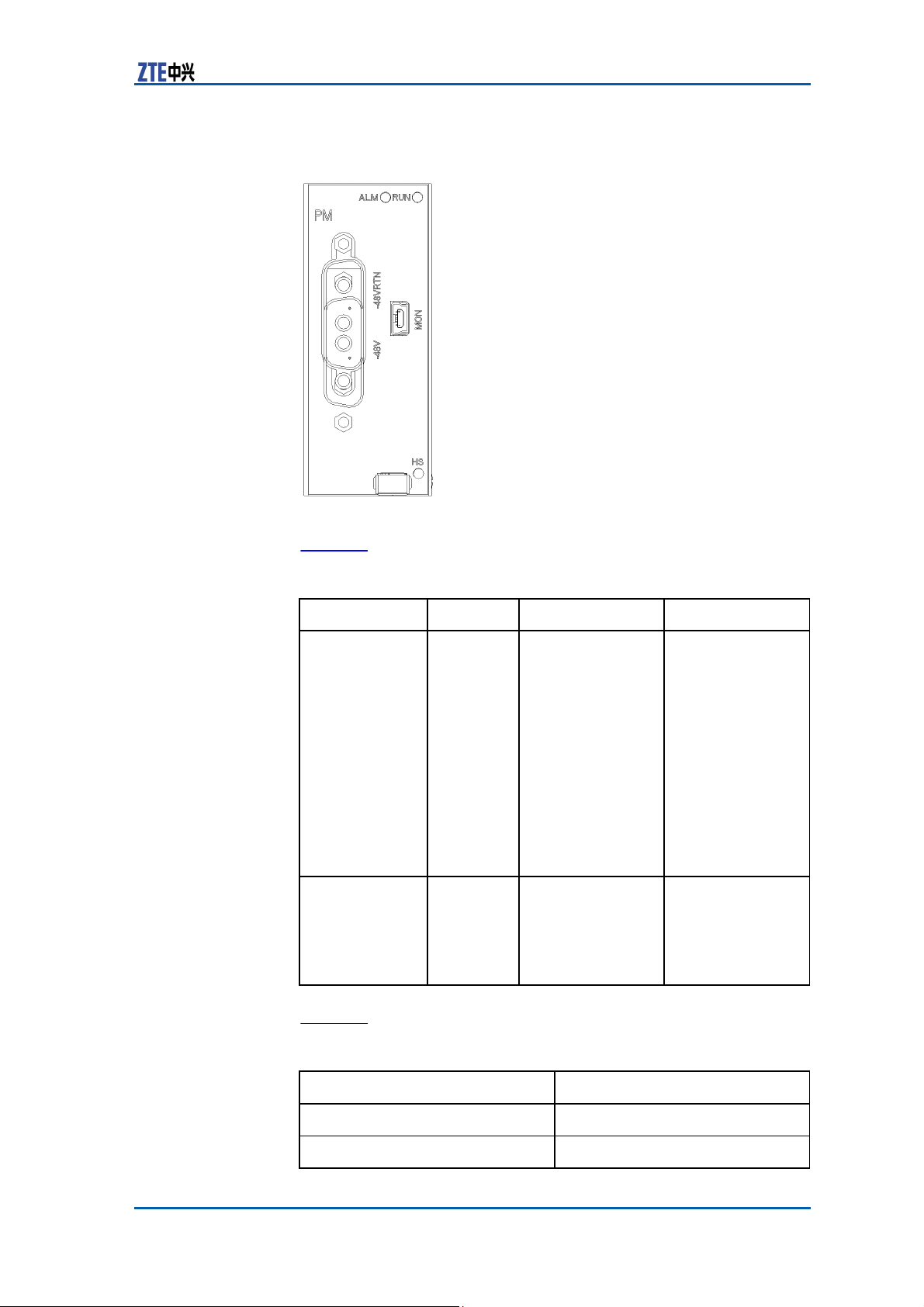
Panel Figure 30 shows the panel of PM module.
32 Confidential and Proprietary Information of ZTE CORPORATION
Page 41
Chapter 2
Modules
FIGURE 30 PM MODULE
P
ANEL
Indicator Table 20 describes the panel indicators of PM
Indicator
RUN
ALM
Color
Green
Red
TABLE 20 PM PANEL INDICATOR
D
ESCRIPTION
Meaning
Running Indicator
Alarm Indicator
Panel Interface Table 21 describes the panel interfaces of PM module.
Interface
TABLE 21 PM PANEL INTERFACE
MON
-48V/-48V RTN
D
ESCRIPTION
Description
RS232 debugging interface
-48V DC input interface
Confidential and Proprietary Information of ZTE CORPORATION 33
module.
Description
Blinks in 5 Hz
when the module
is being powered
on.
Blinks in 1 Hz
when the module
runs normally.
On when the
version is being
started after it
is downloaded
successfully.
Off
when the
module is
abnormal.
On when an alarm
occurs on the
module.
Off when no alarm
occurs on the
module.
Page 42
ZXSDR BS8900 Hardware Manual
RRU
Fan
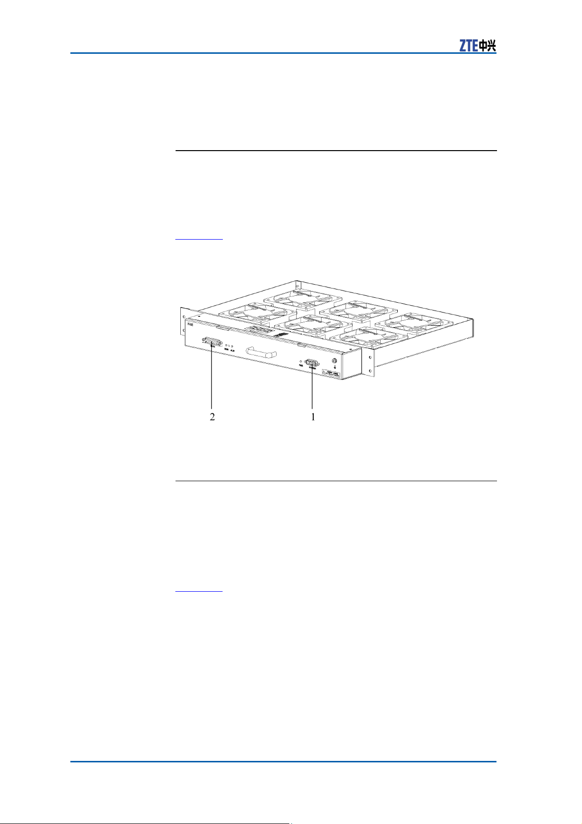
The fan subrack locates in the RF cabinet above the power distribution subrack.
The fan subrack consists of fan control module (FCE), temperature
sensor and 6 fans.
Figure 31 shows the fan subrack structure.
FIGURE 31 FAN
Modules
Subrack
S
UBRACK
STRUCTURE
1. POWER
Power
The power distribution subrack locates in the RF cabinet between
the fan subrack and RF subrack.
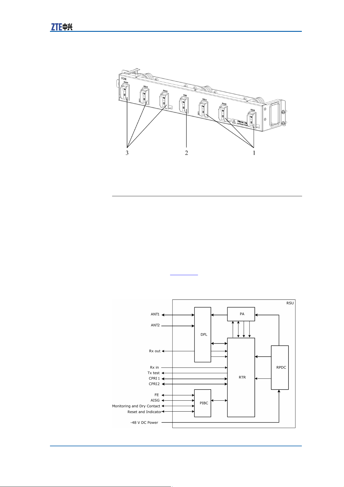
The power distribution subrack consists of 7 branch power circuit
breakers, 2 bus bar jackets, spacer and the shell with the breakers controlling over the power distribution to 6 RSUs and the fan
subrack.
Figure 32 shows the structure of the power distribution subrack.
Distribution Subrack
34 Confidential and Proprietary Information of ZTE CORPORATION
2. MON
Page 43
Chapter 2
Modules
FIGURE 32 POWER DISTRIBUTION SUBRACK
S
TRUCTU RE
1.
RSU
2. FAN
4~6
3. RSU 1~3
Radio
System Unit (RSU)
Function RSU provides the following
�
Communication with the baseband subrack
�
Conversion between air interface RF signals and digital signals
�
RF signal amplification, transmission, and reception
�
Principle The RSU module comprises transceiver board (RTR), power am-
Clock synchronization.
plifier (PA), duplexer (DFL), lightning interface board (PIBC) and
power unit (RPDC). Figure 33 illustrates the RSU’s schematic diagram.
FIGURE 33 RSU SCHEMATIC
functions:
D
IAGRAM
Confidential and Proprietary Information of ZTE CORPORATION 35
Page 44
ZXSDR BS8900 Hardware Manual
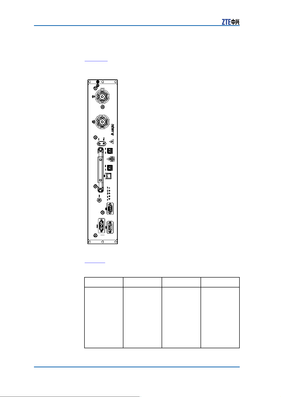
Dimension The dimensions of RSU in mm are : 400.5 (H) × 72.7 (W) × 455.0
(D).
Panel Figure 34 illustrates the RSU
FIGURE 34 RSU
panel.
P
ANEL
Indicators Table 22 describes RSU panel
TABLE 22 RSU PANEL INDICATOR
Indicator
RUN
Color
Green
36 Confidential and Proprietary Information of ZTE CORPORATION
indicators.
D
ESCRIPTION
Meaning
RSU running
indicator
Description
On when RSU is
being reset or
started.
Blinks in 1Hz
when RSU
normally.
Blinks in 5
Hz when the
version is being
downloaded.
Off
when Self
test fails.
runs
Page 45
Indicator
ALM
LNK
RF
Color
Red
Green
Orange
Meaning
RSU alarm
indicator
Optical
interface
indicator
RF status
indicator
Button There is only one button (RST) on the RSU panel. Table 23 de-
scribes the button.
Button
TABLE 23 RSU PANEL BUTTON
RST
D
ESCRIPTION
Description
Reset button
Panel Interfaces Table 24 describes RSU panel interfaces.
Confidential and Proprietary Information of ZTE CORPORATION 37
Chapter 2
Modules
Description
Off when RSU
runs normally
or is being
reset or
started, or RSU
version is being
downloaded.
Blinks in 5
Hz when a
critical alarm
is generated.
Blinks in 1
Hz when a
minor
alarm
is generated.
On when the
link
fiber connection
is normal.
Off
when the
fiber is
disconnected.
Blinks in 5
Hz when the
link is
used as
clock reference
source and the
phase locked
loop is in fast
pull-in status.
Blinks in 0.25
Hz when the
link is used as
clock
reference
source
and the
phase locked
loop is in tracing
status.
Off during no
RF
output
On during RF
output
Page 46

ZXSDR BS8900 Hardware Manual
TABLE 24 RSU PANEL INTERFACE
Interface
Entity at end
A
ANT1(TX/RX)
ANT2(RX)
Rx out
Rx in
RSU
RSU
RSU
Frequency
expansion RSU
TX1 RX1
TX2 RX2
DBG
TEST
MON
RSU
RSU
RSU
RSU
RSU
38 Confidential and Proprietary Information of ZTE CORPORATION
D
ESCRIPTION
Entity at end
B
Transceiver
antenna
Receive
antenna
Frequency
expansion RSU
RSU
BBU or the
upper level
cascaded RSU
Lower level
cascaded RSU
PC
and test
device (test
board)
Testing device
Peripheral
Description
Connected to
transceiver antenna of transmit/receive
main set channel
Connected
to
receive
diversity
channel
antenna
Frequency
expansion
output
interface,
outputting main
set received
signals
Frequency
expansion
input interface,
inputting
diversity
received signals
Connected to
the CPRI optical
interface of BBU
or upper level
cascaded RSU
Connected to
the CPRI optical
interface of
the lower level
cascaded
RSU
Debug interface
and test
interface
Tx
Test signal
interface
Provides input
interface for
four
channels
of dry contact
signals and
RS 485
environment
monitoring
interface
Page 47
Chapter 2
Modules
Interface
AISG
POWER
Entity at end
A
RSU
RSU front
panel
Entity at end
B
Antenna feeder
RF power
supply in
the
power
distribution
subrack
Description
Connected to
antenna feeder
AISG interface
-48 V DC power
input interface
Power
Distribution Module (PDM)
The Power Distribution Module (PDM) provides one -48V DC input
interface and eight -48V DC output interfaces to supply power for
RSU and FCE.
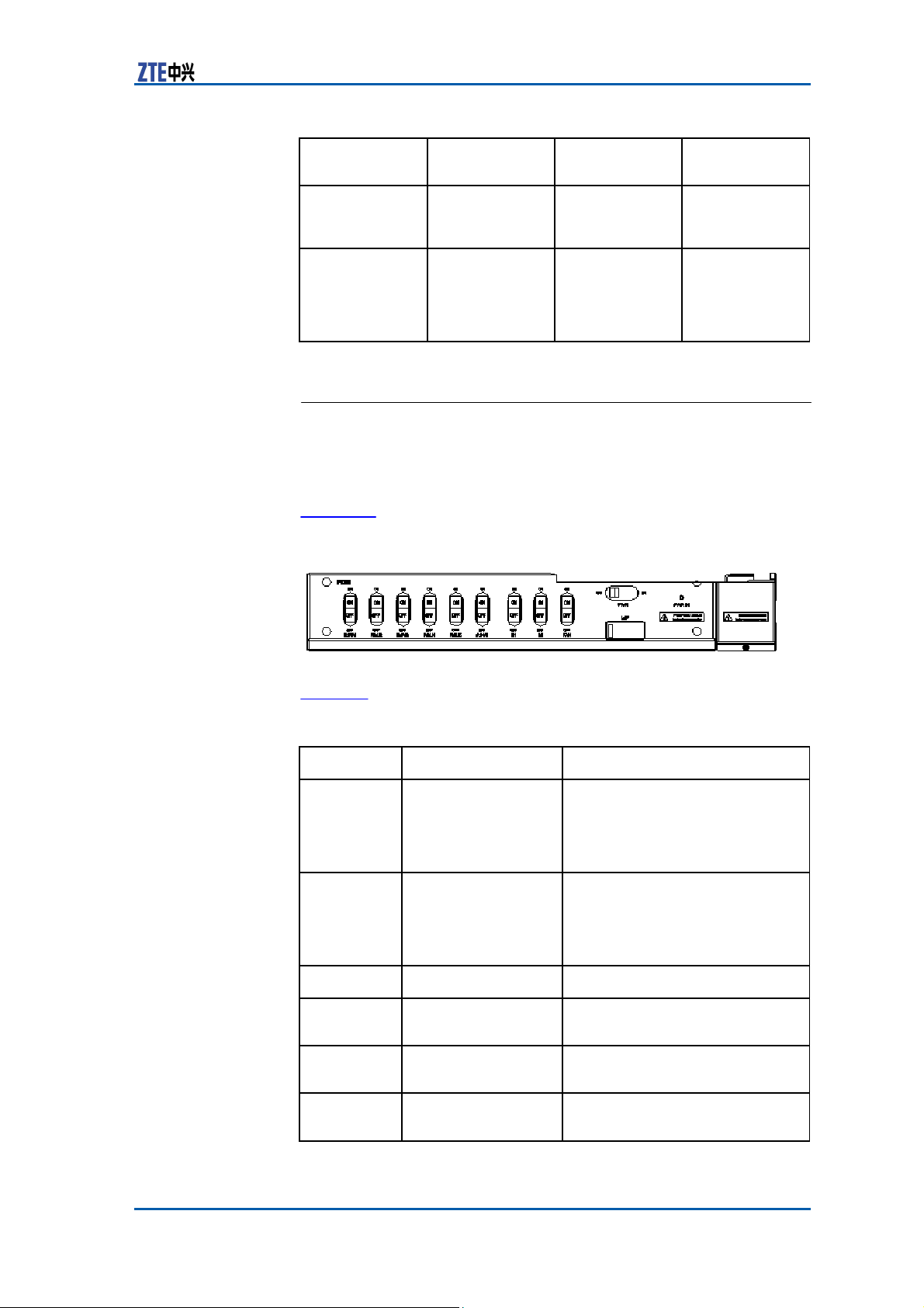
Figure 35 shows the front panel of the PDM.
FIGURE 35 PDM
F
RONT
PANEL
Table 25 describes the PDM front panel.
Silk Print
PWR IN
PWR
Name
Power indicator
Whole equipment
TABLE 25 PDM FRONT
P
ANEL
DESCRIPTION
power supply and
built-in transmission
subrack power
supply
LSP
FAN
Lightning filter
Fan subrack power
supply
RU1
Power supply of RF
unit 1
RU2
Power supply of RF
unit 2
Confidential and Proprietary Information of ZTE CORPORATION 39
Description
That it is on does not mean
that the equipment is powered
on but just means that there is
power supply available for
equipment.
this
ON: Powered on
OFF: Powered off
Lightning protection
ON: Powered on
OFF: Powered off
ON: Powered on
OFF: Powered off
ON: Powered on
OFF: Powered off
Page 48
ZXSDR BS8900 Hardware Manual
Silk Print
RU3
RU4
RU5
RU6
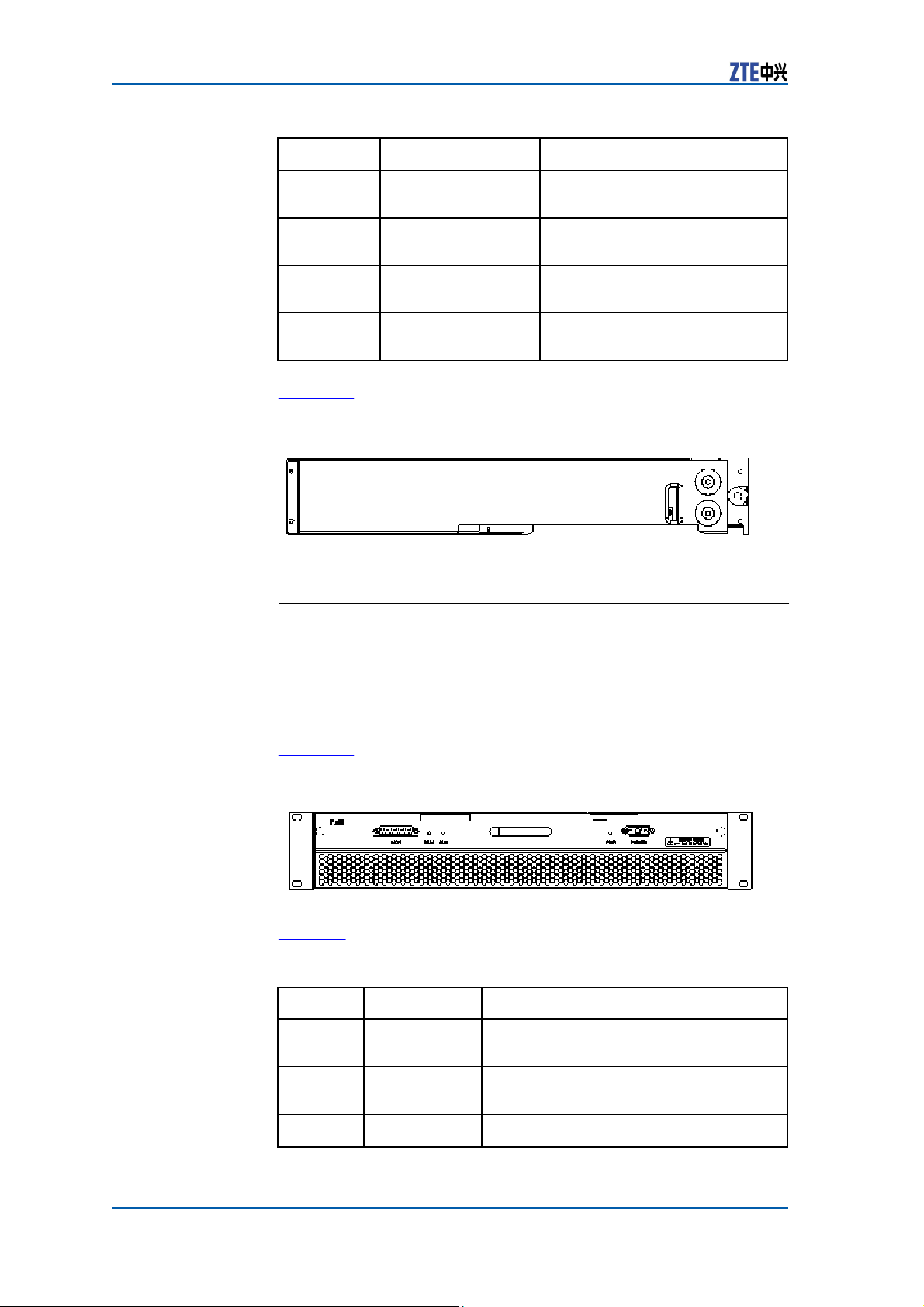
Figure 36 shows the PDM rear panel.
FIGURE 36 PDM REAR
Name
Power supply of RF
unit 3
Power supply of RF
unit 4
Power supply of RF
unit 5
Power supply of RF
unit 6
P
ANEL
Description
ON: Powered on
OFF: Powered off
ON: Powered on
OFF: Powered off
ON: Powered on
OFF: Powered off
ON: Powered on
OFF: Powered off
Fan
Control Module (FCE)
The Fan Control Module (FCE) provides the following functions:
�
Heat dissipation of the integrated equipment
�
Monitoring of fans in the RF cabinet
�
Power supply for fans, rotation control and state report.
Figure 37 shows the FCE front panel.
FIGURE 37 FCE FRONT
Table 26 describes the FCE front panel.
40 Confidential and Proprietary Information of ZTE CORPORATION
TABLE 26 FCE FRONT PANEL
Silk Print
POWER
Name
Power
interface
PWR
Power
indicator
RST
Reset button Resets the whole fan system.
P
ANEL
D
ESCRIPTION
Description
It is connected to the fan power supply of
the power distribution subrack.
That it turns green indicates the fan unit
is powered on.
Page 49

Chapter 2
Modules
Silk Print
ALM
RUN
MON
Name
Alarm
indicator
Run indicator That it flashes indicates the fan system
Monitoring
interface
Description
That it turns red indicates there is an
alarm occurring.
runs normally.
Monitors fans.
Confidential and Proprietary Information of ZTE CORPORATION 41
Page 50

ZXSDR BS8900 Hardware Manual
42 Confidential and Proprietary Information of ZTE CORPORATION
This page is intentionally blank.
Page 51

C
h a p t e r 3
External
Table of Contents
External Cable Layout ........................................................43
Baseband Power Cabinet Input Power
Baseband Power Cabinet Grounding Cable ............................45
Baseband Cabinet and Storage Battery
Baseband Subrack DC Input Power Cable..............................46
Serial Port Monitoring Cable from Power Subrack to Baseband
Subrack ...........................................................................47
Baseband Subrack and RF Cabinet Connecting
External Dry Contact of Baseband Subrack............................49
Baseband Subrack and Lightning Subrack Connecting Ca-
ble ..................................................................................53
Baseband Subrack Ethernet Cable........................................ 54
GPS Arrester and CC Module Connecting RF Cable..................55
Storage Battery Door Control Cable .....................................55
Storage Battery Temperature Monitoring
Storage Battery Water Monitoring Cable ...............................56
E1/T1 Cable on Lightning Subrack LPU .................................56
RF Cabinet DC Input Power Cable ........................................59
Cables
Cable
..........................44
Connecting Cable
Fiber
............... 48
Cable
......................56
.........46
External
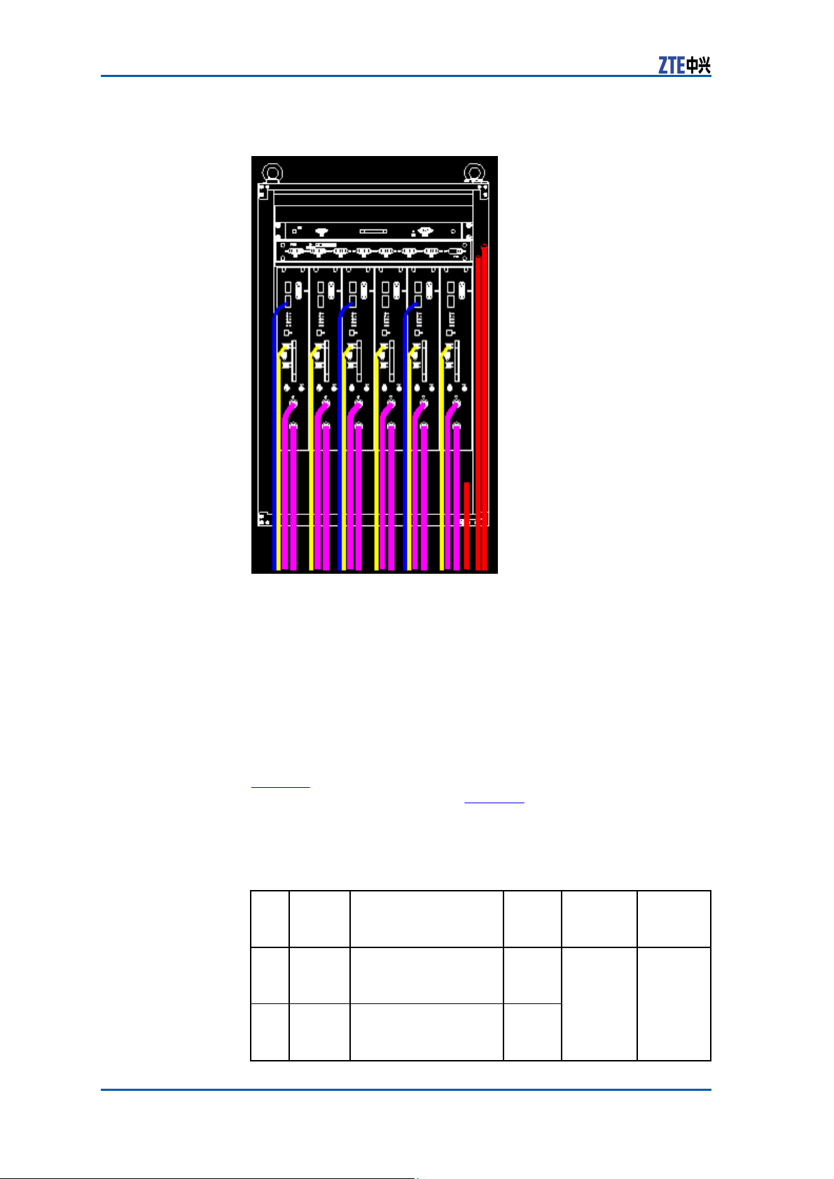
External cables of ZXSDR BS8900 RF cabinet include power
cable, RF cable, fiber and grounding cable. Figure 38 shows the
cable layout.
Confidential and Proprietary Information of ZTE CORPORATION 43
Cable Layout
Page 52
ZXSDR BS8900 Hardware Manual
FIGURE 38 RF CABINET EXTERNAL CABLE
AYOUT
L
– Blue: AISG cable
– Yellow: Fiber
Baseband
Input
Power Cable
Power Cabinet
The baseband power cabinet input cable is a 3×10mm
power cable of RVYZ3×10mm2//ZA-RVY3*10 type.
Table 27
describes definitions
of color codes of the
cabinet power input cable and Table 28 describes technical indices
of the cable.
TABLE 27 BASEBAND POWER CABINET INPUT POWER CABLE
C
ODE
D
EFINITIONS
Pin
1 L
2
Signal
Defini-
tion
N
Signal Description
AC phase line L with
the maximum current
of 60A
AC zero line N with
the maximum current
of 60A
44 Confidential and Proprietary Information of ZTE CORPORATION
– Purple: RF cable
– Red: Power grounding cable
2
outdoor
baseband
C
Cable
Color
Code
Brown
Black
End A
Entity
AC power
distribution
equipment
End B
Entity
Baseband
power
cabinet
power
shielding
box
power
OLOR
Page 53
Chapter 3 External
Cables
Pin
3
Signal
Defini-
tion
PE
Signal Description Cable
AC protection grounding
earth PE
Color
Code
Yellow
and
green
End A
Entity
End B
Entity
TABLE 28 TECHNICAL INDICES OF BASEBAND POWER CABINET
POWER
Insulator
thickness/outer diameter
Jacket thickness
Finished
outer diameter
Insulator
color
Conduct resistance
Allowed temperature range
Fire
resistance capability and Daylight resistance capability
C
ABLE
Name
layer
cable
layer
Index
1.0 mm/4.9 mm
1.2 mm
≤17.6 mm
Blue: N; Brown: L; Yellow and green: PE
≤1.83Ω/km
-40˚C ~ 75˚C
Meet UL1581
2
I
NPUT
Baseband
Grounding
Power Cabinet
Cable
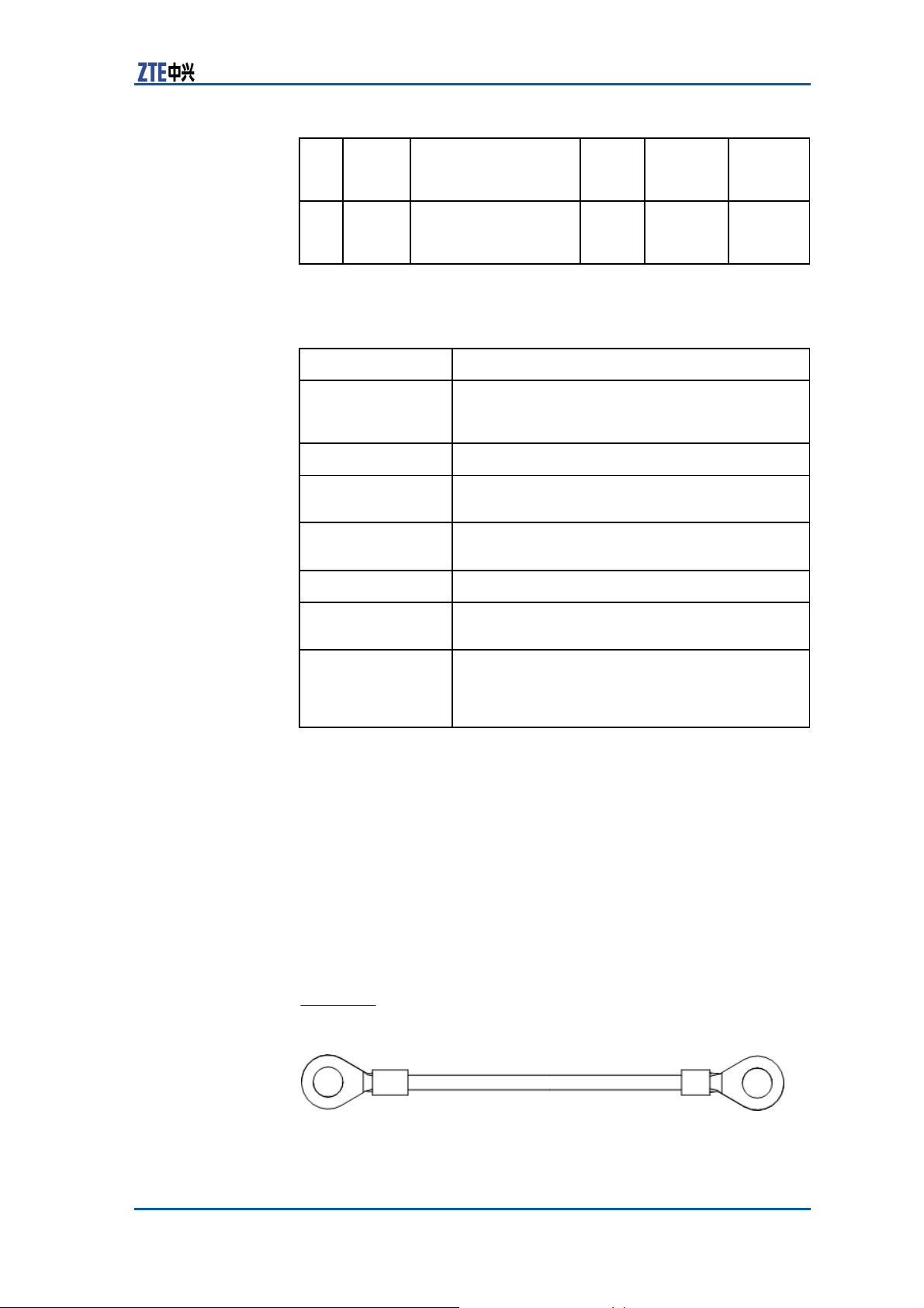
By connecting the baseband power cabinet to the outdoor grounding busbar, the grounding cable provides protection grounding
earth for the system to prevent the equipment from electrostatic
damage and ensure safety and reliable operation of the equipment.
The grounding cable is a 35 mm
2
yellow and green copper wire.
Figure 39 shows the appearance of the grounding cable.
FIGURE 39 GROUNDING
C
ABLE
APPEARANCE
Confidential and Proprietary Information of ZTE CORPORATION 45
Page 54
ZXSDR BS8900 Hardware Manual
Baseband
Cabinet and
Storage Battery Connecting
Cable
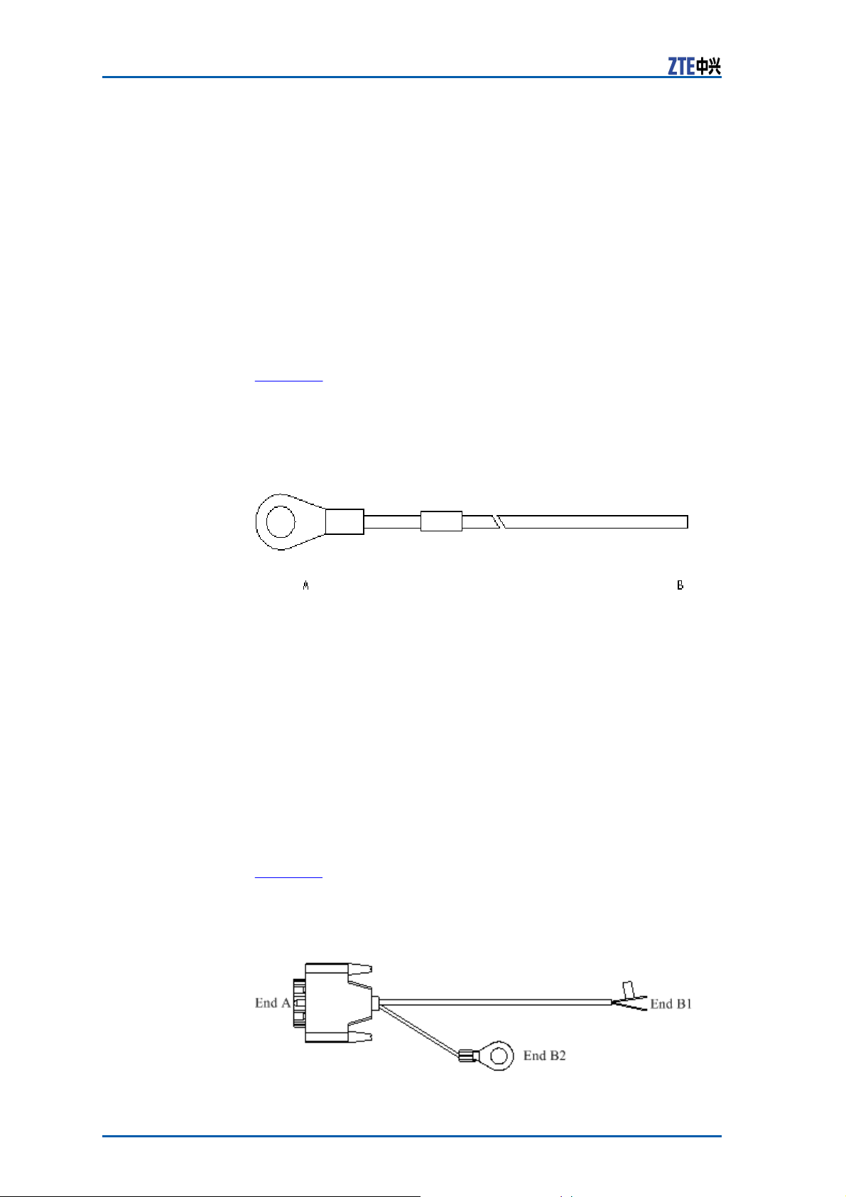
The cable connecting the baseband cabinet to the storage battery
is a 2–core 16mm
minal to connect to the storage battery and 12mm skin is stripped
at end B to connect to the power supply. Both ends of the positive wire are covered with red heat shrink tubes while those of the
negative wire covered with blue heat shrink tubes.
Figure 40 shows the appearance of the cable connecting the base-
band power cabinet to the storage battery.
FIGURE 40 BASEBAND CABINET AND STORAGE BATTERY
C
ABLE
A
PPEARANCE
2
colorful wire. End A is crimped with a M8 ter-
C
ONNECTING
End A is a M8 terminal connected to the wire post in the storage
battery and end B connected to the power output terminal in the
baseband power cabinet.
Baseband
Power
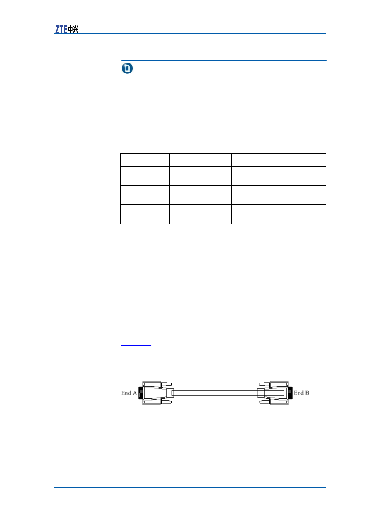
The ZXSDR BS8900 baseband subrack supports –48V DC
power supply only.
Figure 41 shows the appearance of the baseband subrack DC input
power cable.
FIGURE 41 BASEBAND SUBRACK DC INPUT POWER
A
PPEARANCE
Cable
Subrack DC Input
C
ABLE
46
Confidential and Proprietary Information of
ZTE CORPORATION
Page 55
Chapter 3 External
Cables
Note:
1. End A is a 7–core (big hole + small hole ... small hole + big
hole) D-type connector where the connecting lines in small
holes can be unsed. This end is connected to the BBU power
input terminal.
2. End B1 comprises 2.5mm2 black insulating wires that are connected to the power supply output terminal.
Table 29 describes the connection of the power cable.
TABLE 29 POWER CABLE
Connector
End B2
End B1
End B1
Core Color
Yellow and green or
black
Brown
Blue
C
ONNECTION
Signal Description
Protection ground
0 V DC and maximum power of
300 W
-48 V DC and maximum power
of 300 W
Serial
Port Monitoring Cable
from Power Subrack to
Baseband Subrack
The serial port monitoring cable between the power subrack and
baseband subrack is an RS232/RS485 serial port communication
cable, transmitting RS232/RS485 signals and monitoring working
status of power device.
The serial port monitoring cable is a balanced twist pair.
Figure 42 shows the structure of the serial port monitoring cable
between power subrack and baseband subrack.
FIGURE 42 SERIAL PORT MONITORING CABLE BETWEEN
SUBRACK AND BASEBAND
S
UBRACK
P
OWER
Table 30 describes serial port monitoring cable pins.
Confidential and Proprietary Information of ZTE CORPORATION 47
Page 56
ZXSDR BS8900 Hardware Manual
quen
TABLE 30 SERIAL PORT MONITORING CABLE PIN
Se-
1
2
3
4
5
6
7
8
9
This cable cannot provide RS232 interface and RS485 interface
simultaneously.
Name
COM2_RS485_TX+
COM2_RXD
COM2_TXD
COM2_RS485_RX+
GND
COM2_RS485_TX-
GND
COM2_RS485_RX-
GND
Note:
Signal
Description
RS485 signal
output
Receives RS232
signals
Transmits RS232
signals
RS485
signal input
Digital ground
RS485 signal
output
Digital ground
RS485
signal input
Digital ground
D
ESCRIPTION
Pin at
End A
N/A
N/A
N/A
N/A
N/A
N/A
N/A
N/A
N/A
Pin at
End B
1
2
3
4
5
6
7
8
9
Baseband
Subrack and RF
Cabinet Connecting Fiber
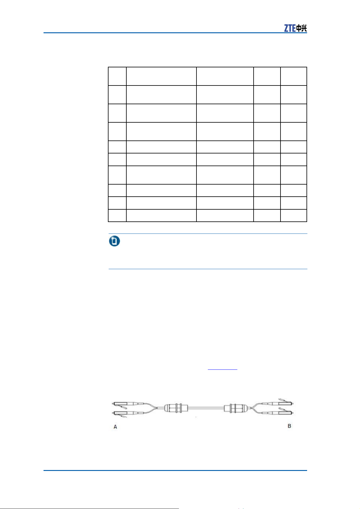
The fiber implements signal exchange between ZXSDR BS8900
48 Confidential and Proprietary Information of ZTE CORPORATION
baseband subrack and RF cabinet.
The fiber used by ZXSDR BS8900 is a single-mode fiber with
LC/LC connectors at both ends. Figure 43 shows the appearance
of the fiber.
FIGURE 43 SINGLE-MODE
F
IBER
APPEARANCE
Page 57
Chapter 3 External
Cables
When connecting the fiber, just make sure that signal receptions
and transmissions are consistent in both ends regardless of its
direction because of nondirectivity of the fiber.
External
Baseband
Dry Contact of
Subrack
The dry contact input/output cable connects the ZXSDR BS8900
to external environment monitoring system to receive dry
contact signals from external equipment and transmit dry contact
signals of the ZXSDR BS8900 .
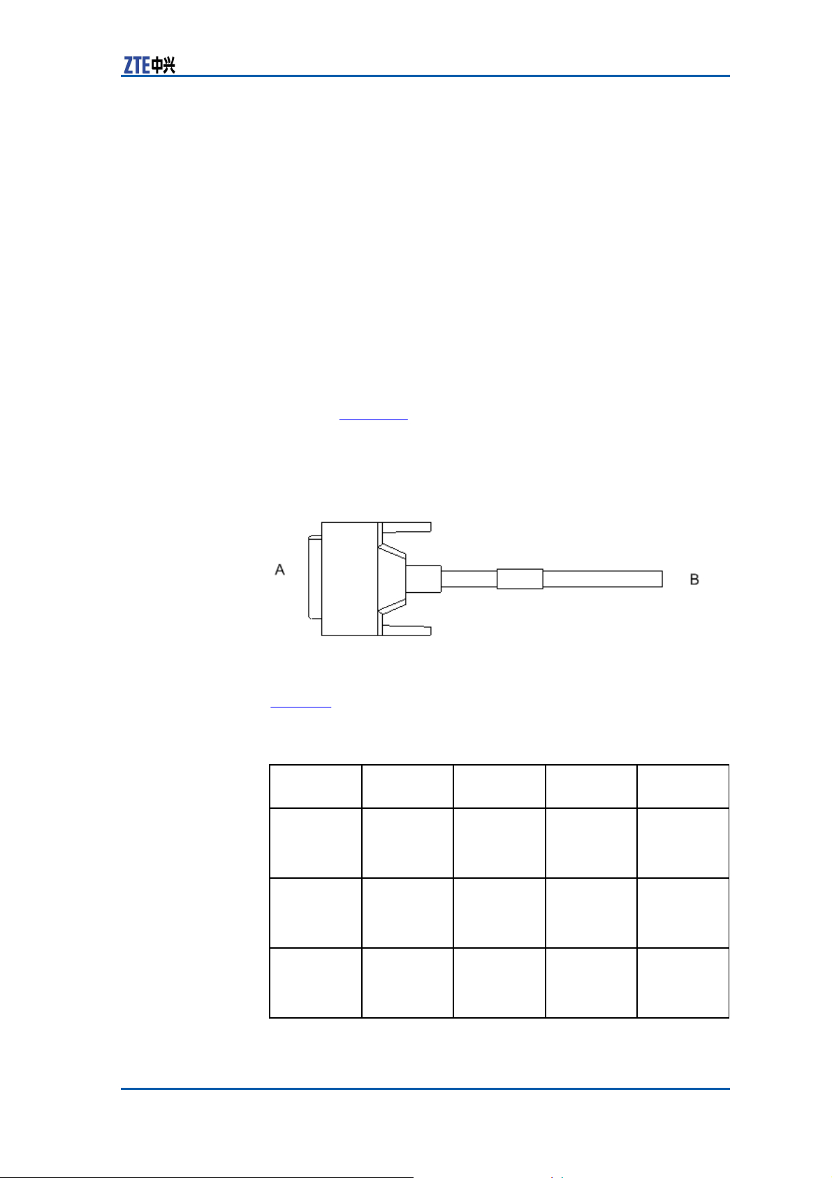
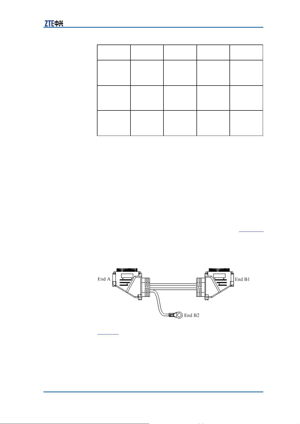
The dry contact input/output cable is a balanced twist pair, as
shown in Figure 44.
FIGURE 44 DRY CONTACT INPUT/OUTPUT
A
PPEARANCE
C
ABLE
Table 31 describes dry contact input cable pins.
TABLE 31 DRY CONTACT INPUT CABLE
D
ESCRIPTION
Sequence
1
2
3
Name
DRY_IN1+ Dry contact
DRY_IN1–
DRY_IN2+
Signal Description
input for
switch
signals
Dry contact
input for
switch
signals
Dry contact
input for
switch
signals
Pin at End
A
N/A
N/A
N/A
Confidential and Proprietary Information of ZTE CORPORATION 49
P
IN
Pin at End
B
1
2
3
Page 58

ZXSDR BS8900 Hardware Manual
Sequence
4
5
6
7
8
9
10
11
12
13
14
15
Name
Signal Description
DRY_IN2–
Dry contact
input for
switch
signals
DRY_IN3+
Dry contact
input for
switch
signals
DRY_IN3–
Dry contact
input for
switch
signals
DRY_IN4+ Dry contact
input for
switch
signals
DRY_IN4– Dry contact
input for
switch
signals
DRY_IN5+ Dry contact
input for
switch
signals
DRY_IN5– Dry contact
input for
switch
signals
DRY_IN6+
Dry contact
input for
switch
signals
DRY_IN6–
Dry contact
input for
switch
signals
DRY_IN7+ Dry contact
input for
switch
signals
DRY_IN7– Dry contact
input for
switch
signals
DRY_IN8+
Dry contact
input for
switch
signals
50 Confidential and Proprietary Information of ZTE CORPORATION
Pin at End
A
N/A
N/A
N/A
N/A
N/A
N/A
N/A
N/A
N/A
N/A
N/A
N/A
Pin at End
B
4
5
6
7
8
9
10
11
12
13
14
16
Page 59

Chapter 3 External
Cables
Sequence
16
17
18
19
20
21
22
23
24
25
26
27
Name
Signal Description
DRY_IN8–
Dry contact
input for
switch
signals
DRY_IN9+
Dry contact
input for
switch
signals
DRY_IN9–
Dry contact
input for
switch
signals
DRY_IN10+
Dry contact
input for
switch
signals
DRY_IN10–
Dry contact
input for
switch
signals
DRY_IN11+ Dry contact
input for
switch
signals
DRY_IN11– Dry contact
input for
switch
signals
DRY_IN12+
Dry contact
input for
switch
signals
DRY_IN12–
Dry contact
input for
switch
signals
DRY_IN13+
Dry contact
input for
switch
signals
DRY_IN13–
Dry contact
input for
switch
signals
DRY_IN14+ Dry contact
input for
switch
signals
Pin at End
A
N/A
N/A
N/A
N/A
N/A
N/A
N/A
N/A
N/A
N/A
N/A
N/A
Pin at End
B
17
18
19
20
21
22
23
24
25
26
27
28
Confidential and Proprietary Information of ZTE CORPORATION 51
Page 60

ZXSDR BS8900 Hardware Manual
Sequence
28
29
30
31
32
Name
Signal Description
DRY_IN14– Dry contact
input for
switch
signals
DRY_IN15+
Dry contact
input for
switch
signals
DRY_IN15– Dry contact
input for
switch
signals
DRY_IN16+
Dry contact
input for
switch
signals
DRY_IN16–
Dry contact
input for
switch
signals
Table 32 describes dry contact output cable pins.
TABLE 32 DRY CONTACT OUTPUT CABLE PIN
Sequence
Name
Signal Description
1
DRY_OUT1+
Dry contact
output
for switch
signals
2
DRY_OUT1–
Dry contact
output
for switch
signals
3
DRY_OUT2+
Dry contact
output
for switch
signals
4
DRY_OUT2–
Dry contact
output
for switch
signals
5
DRY_OUT3+
Dry contact
output
for switch
signals
52 Confidential and Proprietary Information of ZTE CORPORATION
Pin at End
A
N/A
N/A
N/A
N/A
N/A
D
ESCRIPTION
Pin at End
A
N/A
N/A
N/A
N/A
N/A
Pin at End
B
29
31
32
33
34
Pin at End
B
1
14
2
15
3
Page 61
Chapter 3 External
Cables
Sequence
6
7
8
Name
DRY_OUT3–
DRY_OUT4+
DRY_OUT4–
Signal Description
Dry contact
output
for switch
signals
Dry contact
output
for switch
signals
Dry contact
output
for switch
signals
Pin at End
A
N/A
N/A
N/A
Pin at End
B
16
4
17
Baseband Subrack
and Lightning Subrack
Connecting
The cable connecting the baseband subrack to the lightning subrack is used to monitor external and internal environments of the
cabinet and lead the dry contact monitoring cable into the cabinet,
and connect Abis interface if the Abis interface adopts an E1/T1
connection mode.
Both ends A and B of this cable are SCSI connectors. Figure 45
shows its appearance.
FIGURE 45 BASEBAND SUBRACK AND LIGHTNING
C
ONNECTING
CABLE
A
PPEARANCE
Cable
S
UBRACK
Table 33
band subrack and lightning subrack.
describes
Confidential and Proprietary Information of ZTE CORPORATION 53
the
cable connection relationship between
base-
Page 62
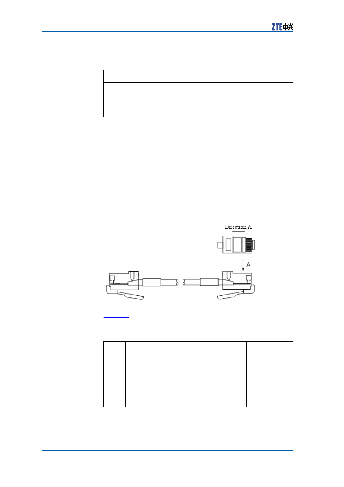
ZXSDR BS8900 Hardware Manual
TABLE 33 CABLE CONNECTION RELATIONSHIP BETWEEN
SUBRACK AND LIGHTNING
End A
Connects the
monitoring/Abis
interface on the
SA board of the
baseband subrack.
B
S
UBRACK
End B
End B1: Connects the BBU interface of the
lighting subrack.
End B2: Connects the grounding terminal of
the cabinet.
ASEBAND
Baseband
Subrack Ethernet
Cable
The Ethernet cable connects Abis interface of baseband subrack to
Abis interface of BSC and can be used as an operation and main-
54 Confidential and Proprietary Information of ZTE CORPORATION
tenance cable when login in a LMT mode is adopted.
Both ends of the Ethernet cable are RJ45 connectors. Figure 46
shows the appearance of the cable.
FIGURE 46 ETHERNET
C
ABLE
APPEARANCE
Table 34 describes Ethernet cable pins.
TABLE 34 ETHERNET CABLE
D
ESCRIPTION
Sequenc
1
2
3
4
Name
Description
Abis/Iub_ETH_TX+ Transmits signals
Abis/Iub_ETH_TX- Transmits signals
Abis/Iub_ETH_RX+ Receives signals
Abis/Iub_ETH_RX- Receives signals
P
IN
Pin at
End A
1
2
3
6
Pin at
End B
1
2
3
6
Page 63
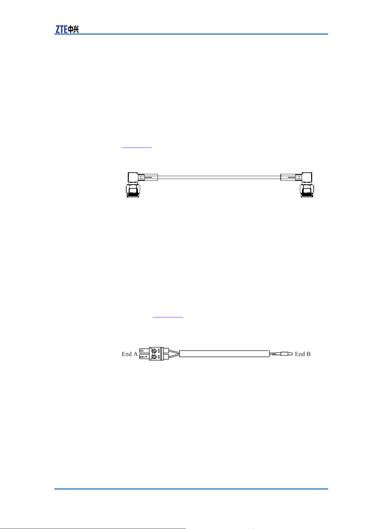
Chapter 3 External
Cables
GPS Arrester and CC
Module Connecting
Cable
RF
The GPS jumper connects GPS arrester to CC module and provides
GPS clock input signals for CC to convert these signals into various
clock signals for ZXSDR BS8900 to use.
Figure 47 shows the appearance of the GPS jumper.
FIGURE 47 GPS
J
UMPER
APPEARANCE
One end of the GPS jumper is connected to the output terminal of
the GPS arrester and the other connected to the ANT interface of
the CC board.
Storage Battery Door
Control
Cable
The storage battery door control cable is used to monitor door
control of the storage battery cabinet and its appearance is as
shown in Figure 48.
FIGURE 48 STORAGE BATTERY DOOR CONTROL
A
PPEARANCE
End A is
the lightning subrack and end B connected with the door control
magnetism.
connected
with the environment
monitoring
Confidential and Proprietary Information of ZTE CORPORATION 55
C
ABLE
cable led from
Page 64
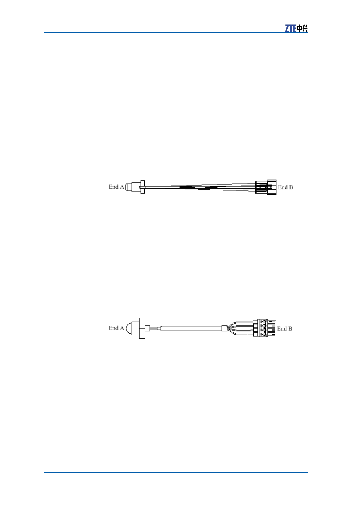
ZXSDR BS8900 Hardware Manual
Storage Battery
Temperature Monitoring
Cable
The storage battery temperature monitoring cable is used to monitor the temperature in the storage battery and report monitoring
results to the baseband subrack.
Figure 49 shows the appearance of the temperature monitoring
cable.
FIGURE 49 TEMPERATURE MONITORING
A
PPEARANCE
C
ABLE
Storage Battery Water
Monitoring
The storage battery water monitoring cable is used to monitor
whether the storage battery is watered and transmit electrical signals of the water sensor to the baseband subrack.
Figure 50 shows the appearance of the storage battery water mon-
itoring cable.
FIGURE 50 STORAGE BATTERY WATER MONITORING
A
PPEARANCE
End A is a water sensor and put on the bottom of the storage
battery cabinet while end B is connected with the environment
monitoring cable led from the lightning subrack of the baseband
cabinet.
Cable
C
ABLE
E1/T1
Subrack
Cable on Lightning
LPU
The E1/T1 cable on lightning subrack LPU transmits E1/T1 signals
between Abis interfaces or cascaded
56 Confidential and Proprietary Information of ZTE CORPORATION
4–channel E1/T1 cable and 8–channel E1/T1 cable.
BTSs and is classified into
Page 65
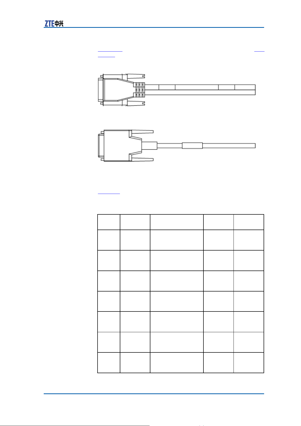
Chapter 3 External
Cables
Figure 51 shows the structure of the 8–channel E1/T1 cable. Figure 52 shows the structure of the 4–channel E1/T1 cable.
FIGURE 51 8–CHANNEL
E1/T1 C
ABLE
FIGURE 52 4–CHANNEL
E1/T1 C
ABLE
One end of the cable is a DB44 connector to connect to the lightning subrack and the other end contains 16 or 32 lines to connect
to the transmission equipment.
Table 35 describes E1/T1 cable pins.
TABLE 35 DESCRIPTION OF E1/T1 CABLE PINS ON
LPU
Sequence
1
Name
E1_TX1+
Signal Description
Transmits signal
positive (micro-coax
1 signal)
2
E1_TX1-
Transmits signal
negative (micro-coax
1 shielding ground)
3
E1_RX1+
Receives signal
positive (micro-coax
2 signal)
4
E1_RX1-
Receives signal
negative (micro-coax
2 shielding ground)
5
E1_TX2+
Transmits signal
positive (micro-coax
3 signal)
6
E1_TX2-
Transmits signal
negative (micro-coax
3 shielding ground)
7
E1_RX2+
Transmits signal
positive (micro-coax
4 signal)
Confidential and Proprietary Information of ZTE CORPORATION 57
L
IGHTNING
Pin at End
A
1-2-inner
1-2-outer
1-1-inner
1-1-outer
1-4-inner
1-4-outer
1-3-inner
SUBRACK
Pin at End
B
25
24
23
22
4
3
2
Page 66

ZXSDR BS8900 Hardware Manual
Sequence
8
9
10
11
12
13
14
15
16
17
18
19
20
21
22
Name
E1_RX2-
E1_TX3+
E1_TX3-
E1_RX3+
E1_RX3-
E1_TX4+
E1_TX4-
E1_RX4+
E1_RX4-
E1_TX5+
E1_TX5-
E1_RX5+
E1_RX5-
E1_TX6+
E1_TX6-
Signal Description
Receives signal
negative (micro-coax
4 shielding ground)
Transmits signal
positive (micro-coax
5 signal)
Transmits signal
negative (micro-coax
5 shielding ground)
Receives signal
positive (micro-coax
6 signal)
Receives signal
negative (micro-coax
6 shielding ground)
Transmits signal
positive (micro-coax
7 signal)
Transmits signal
negative (micro-coax
7 shielding ground)
Receives signal
positive (micro-coax
8 signal)
Receives signal
negative (micro-coax
8 shielding ground)
Transmits signal
positive (micro-coax
1 signal)
Transmits signal
negative (micro-coax
1 shielding ground)
Receives signal
positive (micro-coax
2 signal)
Receives signal
negative (micro-coax
2 shielding ground)
Transmits signal
positive (micro-coax
3 signal)
Transmits signal
negative (micro-coax
3 shielding ground)
58 Confidential and Proprietary Information of ZTE CORPORATION
Pin at End
A
1-3-outer
1-6-inner
1-6-outer
1-5-inner
1-5-outer
1-8-inner
1-8-outer
1-7-inner
1-7-outer
2-2-inner
2-2-outer
2-1-inner
2-1-outer
2-4-inner
2-4-outer
Pin at End
B
1
8
7
6
5
12
11
10
9
44
43
14
13
42
41
Page 67
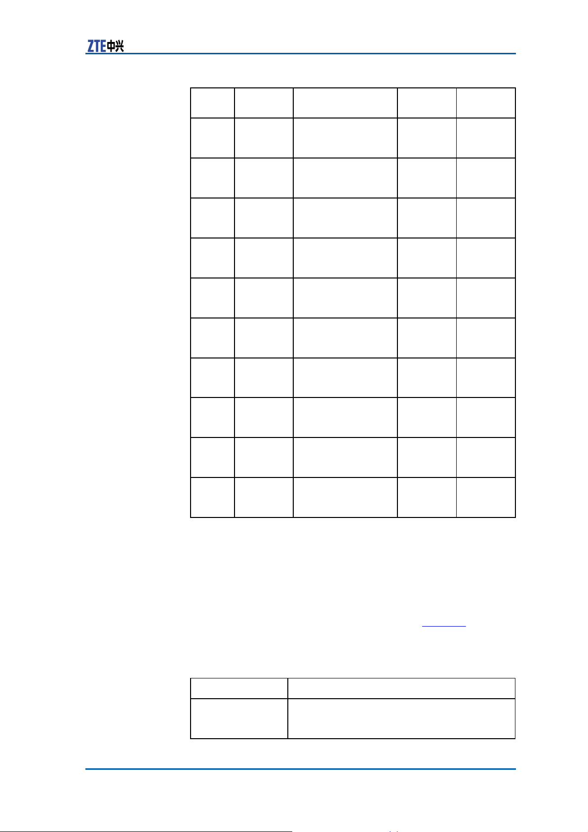
Chapter 3 External
Cables
Sequence
23
24
25
26
27
28
29
30
31
32
Name
E1_RX6+
E1_RX6-
E1_TX7+
E1_TX7-
E1_RX7+
E1_RX7-
E1_TX8+
E1_TX8-
E1_RX8+
E1_RX8-
Signal Description
Receives signal
positive (micro-coax
4 signal)
Receives signal
negative (micro-coax
4 shielding ground)
Transmits signal
positive (micro-coax
5 signal)
Transmits signal
negative (micro-coax
5 shielding ground)
Receives signal
positive (micro-coax
6 signal)
Receives signal
negative (micro-coax
6 shielding ground)
Transmits signal
positive (micro-coax
7 signal)
Transmits signal
negative (micro-coax
7 shielding ground)
Receives signal
positive (micro-coax
8 signal)
Receives signal
negative (micro-coax
8 shielding ground)
Pin at End
A
2-3-inner
2-3-outer
2-6-inner
2-6-outer
2-5-inner
2-5-outer
2-8-inner
2-8-outer
2-7-inner
2-7-outer
Pin at End
B
40
39
38
37
36
35
34
33
32
31
RF
Cabinet DC Input Power
Cable
The RF cabinet DC input power cable is a 3×10mm2 outdoor power
cable of RVYZ3×10mm2//ZA-RVY3*10 type. Table 36 describes
technical indices of the cable.
TABLE 36 RF CABINET DC INPUT POWER CABLE
I
NDICES
Insulator
Name
layer
Index
1.0 mm/4.9 mm2
thickness/outer diameter
Confidential and Proprietary Information of ZTE CORPORATION 59
T
ECHNICAL
Page 68

ZXSDR BS8900 Hardware Manual
Jacket thickness
Finished
outer diameter
Insulator
color
Conduct resistance
Allowed temperature range
Fire
pability and Daylight resistance capability
resistance ca-
cable
layer
1.2 mm
≤17.6 mm
Blue: -48V; Brown: -48 V GND; Yellow
and green: PE
≤1.83Ω/km
-40 75
Meet UL1581
60 Confidential and Proprietary Information of ZTE CORPORATION
Page 69

C
h a p t e r 4
GPS Antenna
System
Table of Contents
GPS Antenna Feeder System
GPS Antenna ....................................................................62
GPS Feeder.......................................................................63
GPS Arrester.....................................................................64
GPS Feeder Connector........................................................65
GPS Grounding
Structure
Kit
............................................................. 66
Feeder
.................................61
GPS Antenna Feeder
System
GPS signals provide system clock and frequency reference. The
GPS antenna feeder system receives navigation and location signals from GPS satellites and demodulates these signals into frequency and clock signals for relevant units of the ZXSDR BS8900
.
Structure
Figure 53 shows the structure of the ZXSDR BS8900 GPS
antenna feeder system.
Confidential and Proprietary Information of ZTE CORPORATION 61
Page 70
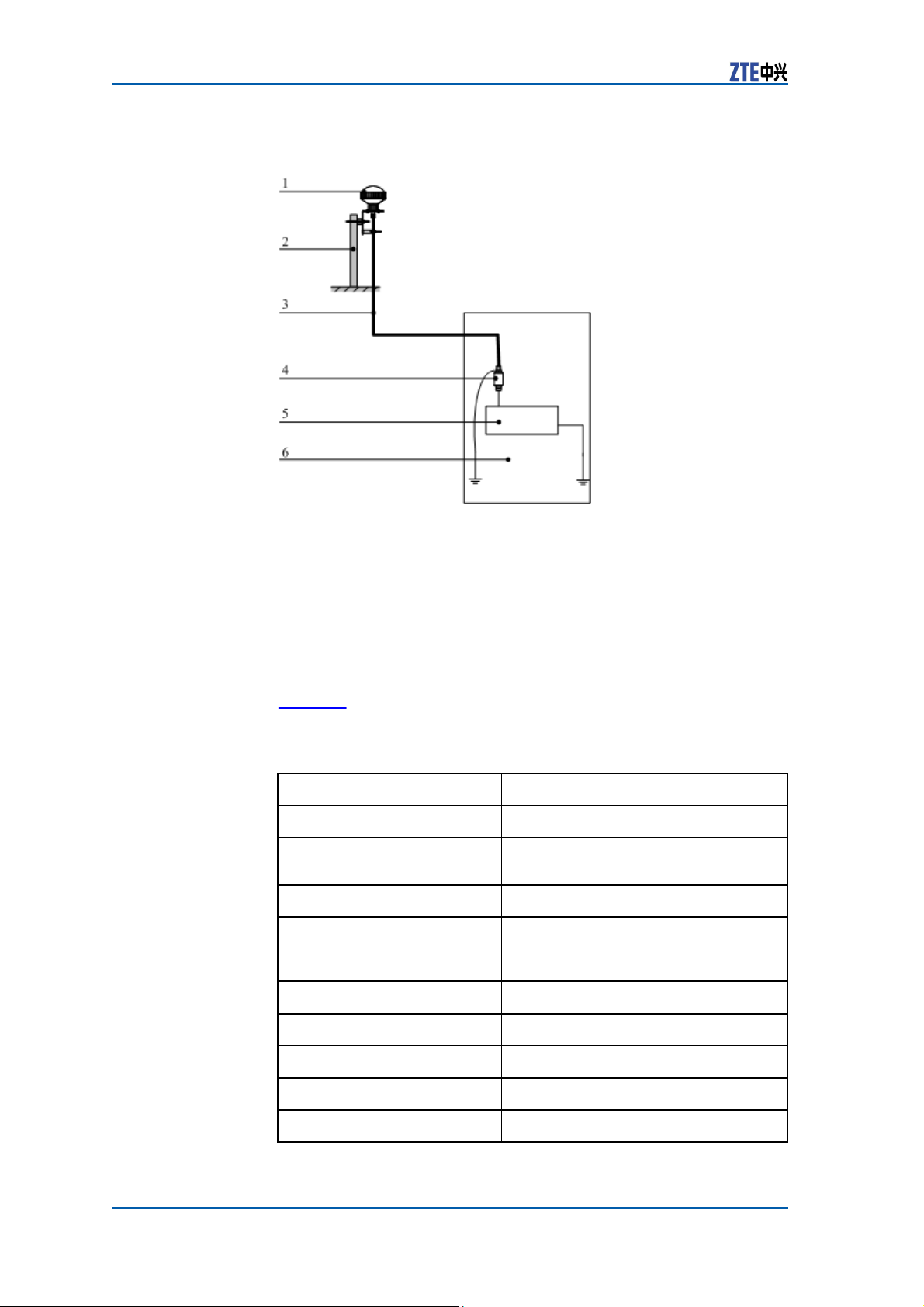
ZXSDR BS8900 Hardware Manual
FIGURE 53 GPS ANTENNA FEEDER SYSTEM
S
TRUCTURE
1. GPS antenna
2. GPS feeder pole
3. Feeder
4. GPS arrester
5. Baseband
6. Baseband power cabinet
GPS
Antenna
Description GPS antenna is an active antenna. GPS antenna receives
Technical Indices Table 37 lists the technical indices and specifications of GPS an-
62 Confidential and Proprietary Information of ZTE CORPORATION
satellite signals and sends them to clock module.
tenna.
TABLE 37 GPS ANTENNA TECHNICAL
Index name
Frequency
Gain
Polarization
Impedance
Interface
Noise coefficient
Power supply voltage
power supply current
Working temperature
Storage temperature
I
NDICES
1.57542 GHz
38 dBi ± 2 dBi (including low noise amplifier’s gain).
right hand circular polarization
50 Ω
NF
<1.5 dB
5 V DC~12 V DC
<35 mA
-30 ~70
-45 ~85
Index Specification
GPS
Page 71
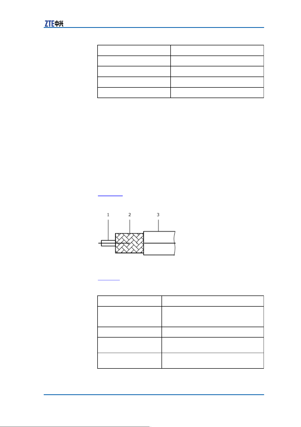
Chapter 4 GPS Antenna Feeder System
Index name
Rain-proof
Material of antenna shield
weight
Support tube dimension
Index Specification
air-sealing
UPVC
450 g
Φ27 mm x 300 mm
GPS
Feeder
Functions The GPS feeder performs following
�
Connects the GPS antenna with the clock module.
�
Transmits signals received by the GPS antenna to the clock
module for proper processing.
�
Transmits the DC 5 V power generated by the clock module to
the GPS antenna as the working voltage.
�
PE insulation impedance is 50 ohm. It is one-layer bare copper
Structure When the GPS feeder length is less than 100m, 1/4" RF coaxial
braided shielded.
cable can be used. 1/4" RF coaxial cable appearance is shown in
Figure 54
FIGURE 54 GPS FEEDER
S
TRUCTURE
1. Cable core
2. Shield cover
Technical Indices Table 38 lists the technical indices of GPS feeder cable.
TABLE 38 GPS FEEDER CABLE TECHNICAL
Technical Parameter
Name
Characteristic impedance
Inner conductor calibration outer diameter
Insulation
tion outer diameter
layer
calibra-
1/4″ foam polyethylene insulation wrinkle
copper tube
cable.
50 Ω
2.6 mm.
6 mm.
Confidential and Proprietary Information of ZTE CORPORATION 63
functions:
3. Insulating layer
I
NDICES
Index Scope
external conductor
RF coaxial
Page 72
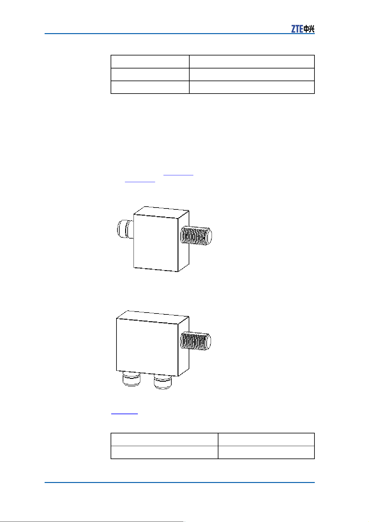
ZXSDR BS8900 Hardware Manual
VSWR
Attenuation
Technical Parameter
Index Scope
1.2
18.9 dB /100 m. at 1.57542 GH.
GPS
Arrester
Description The GPS arrester is installed between the coaxial feeder that con-
nects with GPS antenna and the antenna feeder RF cable on the
clock module to prevent the clock module and other modules from
Structure Two kinds of GPS arresters are available at present: one-in-one
the transient over—voltage caused by lightning induction.
and two-in-one. Figure 55 shows the structure of the former type
and Figure 56 illustrates that of the latter.
FIGURE 55 ONE-IN-ONE GPS ARRESTER
S
TRUCTURE
FIGURE 56 TWO-IN-ONE GPS ARRESTER
S
TRUCTURE
Technical Indices Table 39 lists the technical indices of one-in-one GPS arrester.
TABLE 39 ONE-IN-ONE GPS ARRESTER TECHNICAL
Index
Impedance
Specification
50 Ω
I
NDICES
64 Confidential and Proprietary Information of ZTE CORPORATION
Page 73
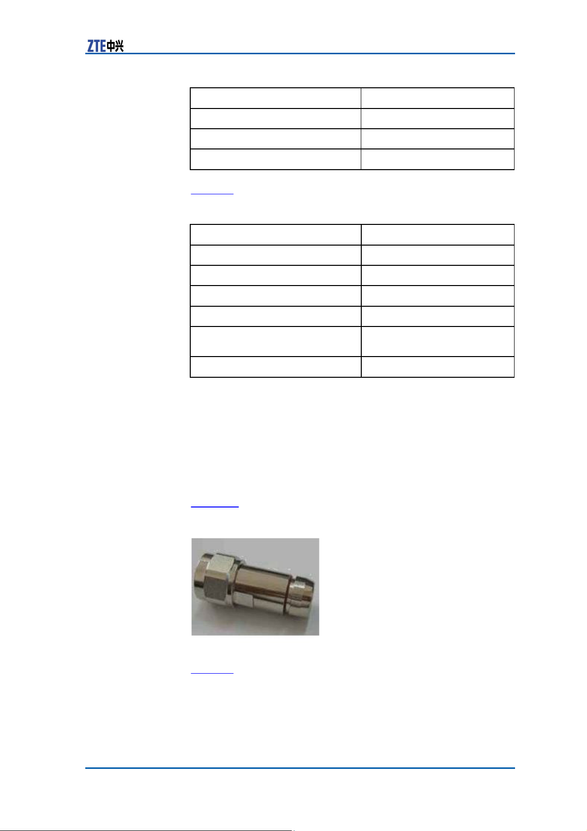
Chapter 4 GPS Antenna Feeder System
Index
VSWR
Insertion loss
Working frequency
Specification
≤1.2
≤0.2 dB
1.5
1.6GHz
Table 40 lists the technical indices of two-in-one GPS arrester.
TABLE 40 TWO-IN-ONE GPS ARRESTER TECHNICAL
Index
Impedance
VSWR
insertion loss
Maximum transmitting power
rated through-current capacity
(8/20µs)
Working frequency
Specification
50 Ω
≤1.2
≤4.0 dB
50 W
10 kA
1500 ~ 1610MHz
I
NDICES
GPS
Feeder Connector
Description The GPS feeder connector is an N type straight cable clip 1/4” con-
nector. GPS feeder connector is a small/medium power connector with thread connection mechanism, and has wide application
in connecting coaxial RF cables in radio devices and instruments.
GPS feeder connector’s impedance is 50 ohm.
Structure Figure 57 shows the GPS feeder connector
FIGURE 57 GPS FEEDER CONNECTOR
S
TRUCTURE
Technical Indices Table 41 lists the technical indices of GPS feeder
Confidential and Proprietary Information of ZTE CORPORATION 65
structure.
connector.
Page 74
ZXSDR BS8900 Hardware Manual
TABLE 41 GPS FEEDER CONNECTOR TECHNICAL
Model
Characteristic Impedance
Frequency scope
dielectric strength
VSWR
Inner conductor contact resistance
external conductor contact resistance
insulation resistance
cable connecting sustainability ≥300 N
Temperature
humidity
Corroding gas environment
Index name
NDICES
I
Specification
NM-1/4”L
50 Ω
0 GHz ~11 GHz
2500 V minimum sea level
≤1.10
0 GHz ~ 3 GHz
≤1.0 mΩ
≤0.25 mΩ
≥5000 MΩ
-65 ~ +165
≤95%
No acid or alkaline gas
GPS
Grounding Kit
Structure When the GPS feeder uses 1/4" RF coaxial cable, the GPS feeder
grounding kit should be glue free. Structure of GPS grounding kit
is shown in Figure 58.
66 Confidential and Proprietary Information of ZTE CORPORATION
Page 75
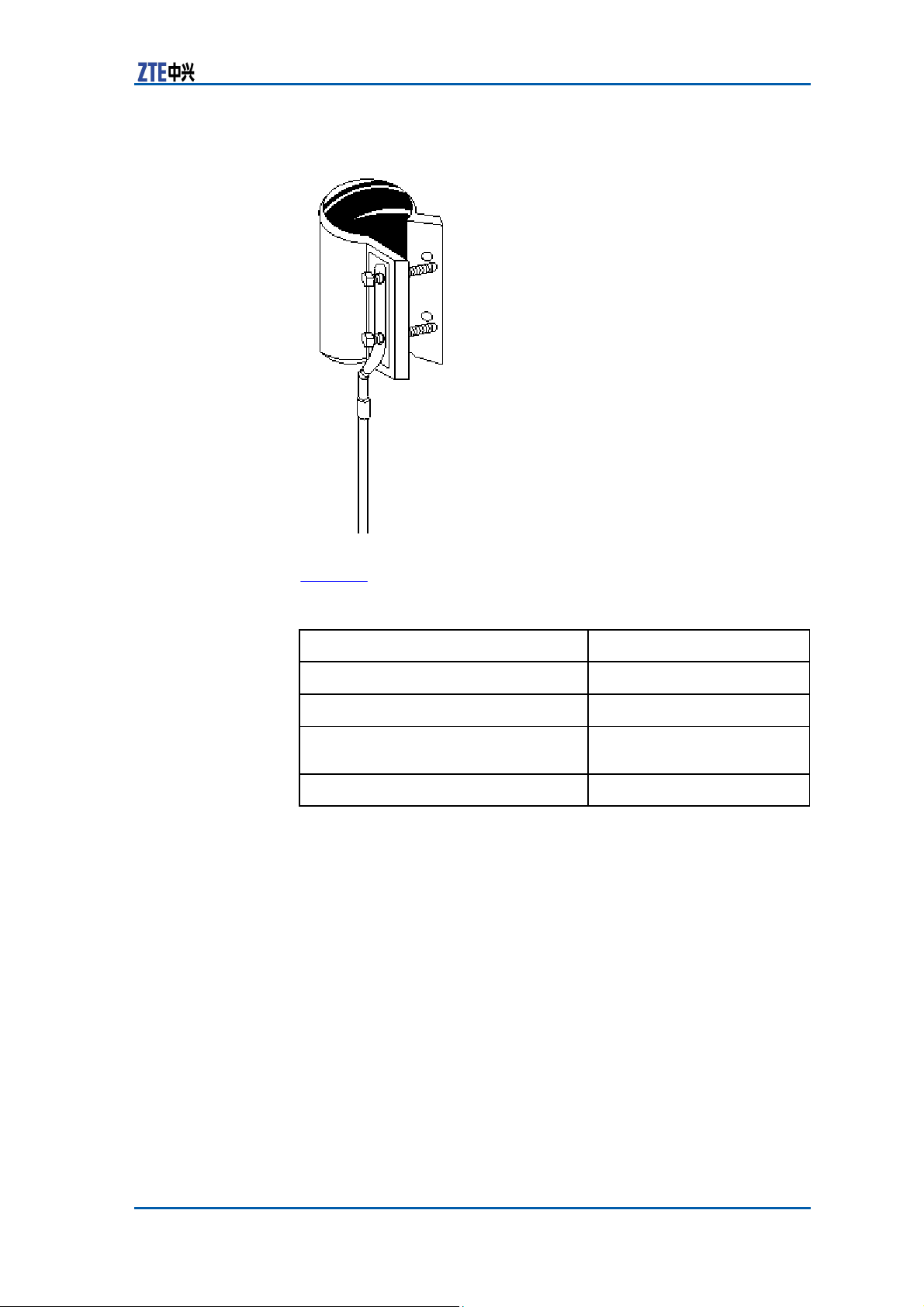
Chapter 4 GPS Antenna Feeder System
FIGURE 58 GPS GROUNDING KIT
S
TRUCTURE
Technical Indices Table 42 lists the GPS feeder grounding kit technical
Technical Parameter
TABLE 42 GPS FEEDER GROUNDING KIT TECHNICAL
Material of grounding kit
Material of copper braid belt
Grounding cable copper core cross-sec-
stainless steel
purple copper
10 mm2.
tional area
Grounding cable length
800 mm.
I
Specification
Confidential and Proprietary Information of ZTE CORPORATION 67
NDEXES
indexes.
Page 76

ZXSDR BS8900 Hardware Manual
68 Confidential and Proprietary Information of ZTE CORPORATION
This page is intentionally blank.
Page 77

C
h a p t e r 5
configuration with
common
ZXSDR
BS8900
antenna
Main Antenna
System
Table of Contents
Main Antenna Feeder System
Antenna
Feeder Structure ............................................................... 75
...........................................................................75
Structure
Feeder
................................ 69
Main Antenna Feeder
System
The typical configurations for ZXSDR BS8900 main antenna
feeder system described below includes:
�
ZXSDR BS8900 configuration with common antenna
�
ZXSDR BS8900 configuration with common antenna, AISG
dual power amplifier
�
ZXSDR BS8900 configuration with electronic adjustment
antenna(1)
�
ZXSDR BS8900 configuration with electronic adjustment
antenna(2)
�
ZXSDR BS8900 configuration with electronic adjustment
antenna, AISG dual power amplifier
In this configuration, generally ZXSDR BS8900 installation
position is near antenna and they are all installed on the building top. ZXSDR BS8900 is connected to the antenna by
1/2″feeder directly, occasionally 5/4″or 7/8″feeder is adopted, as
shown inFigure 59.
Confidential and Proprietary Information of ZTE CORPORATION 69
Structure
Page 78
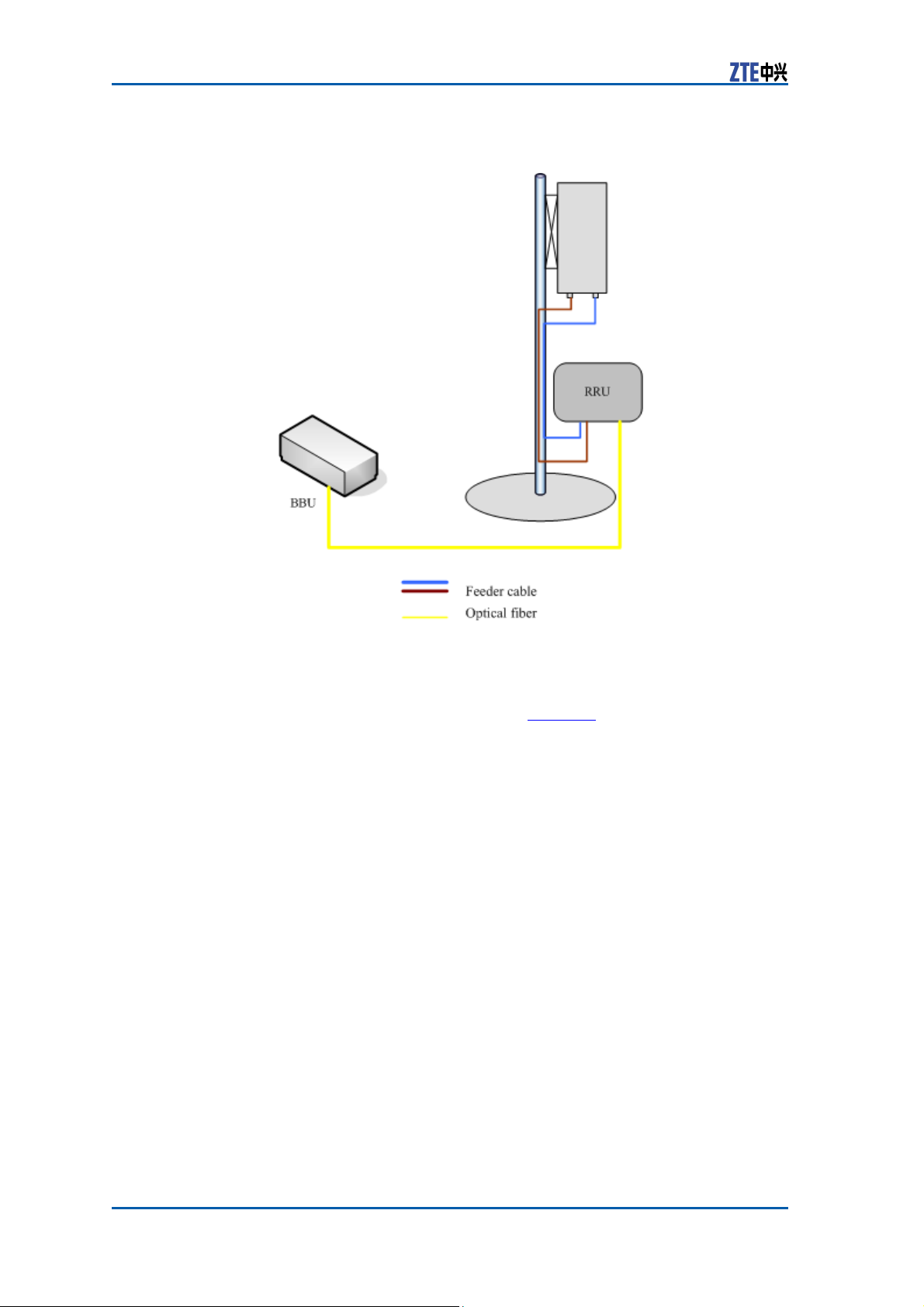
ZXSDR BS8900 Hardware Manual
FIGURE 59 ZXSDR BS8900 CONFIGURED WITH
C
OMMON
ANTENNA
ZXSDR
configuration with
common
BS8900
antenna,
70 Confidential and Proprietary Information of ZTE CORPORATION
.
In this configuration, generally ZXSDR BS8900 is installed on
the tower. ZXSDR BS8900 is connected to the antenna by
5/4″or 7/8″feeder, as shown in Figure 60.
Page 79
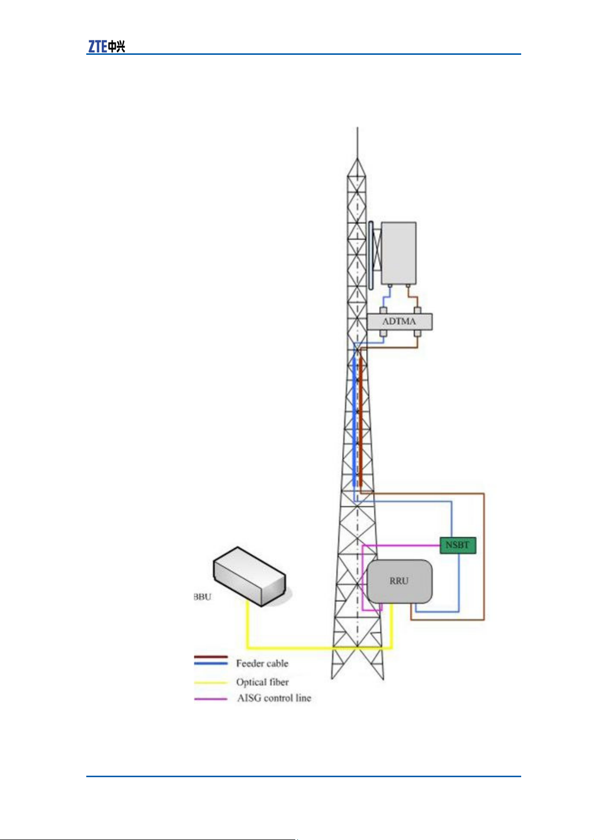
amplifier
F 60 ZXSDR
BS8900
C C
AISG dual power
Chapter 5 Main Antenna Feeder System
IGURE ONFIGURATION
ANTENNA, AISG DUAL POWER
A
MPLIFIER
WITH OMMON
Confidential and Proprietary Information of ZTE CORPORATION 71
Page 80
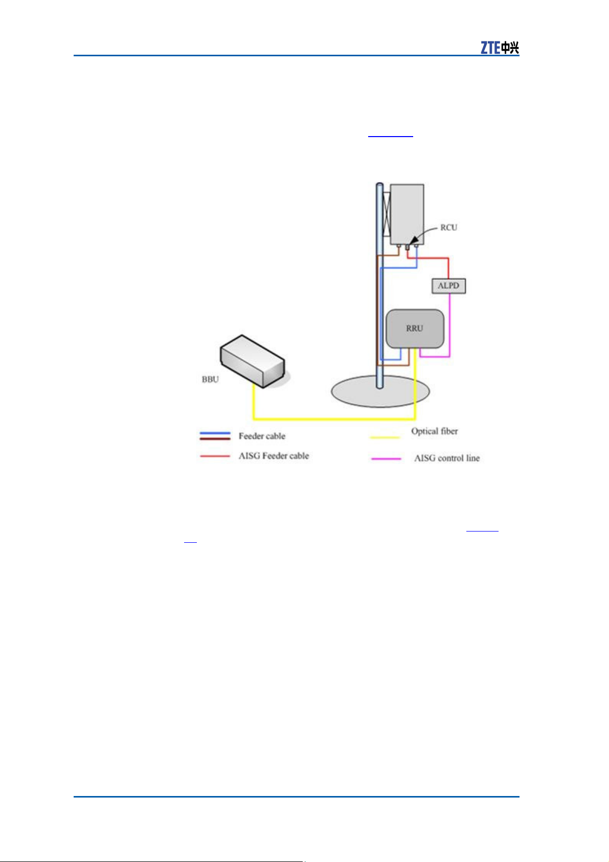
ZXSDR BS8900 Hardware Manual
ZXSDR
BS8900
configuration
with
electronic
adjustment
antenna
(1)
In this configuration, generally ZXSDR BS8900 installed near the
antenna on the building top. ZXSDR BS8900 is con- nected to
the antenna by 1/2″feeder directly, occasionally 5/4″or
7/8″feeder is adopted, as shown in Figure 61.
FIGURE 61 ZXSDR BS8900 CONFIGURATION
ADJUSTMENT
A
NTENNA
(1)
ZXSDR
BS8900
configuration
with
electronic
In this configuration, generally ZXSDR BS8900 is installed near
the top of the tower. ZXSDR BS8900 is connected to the
antenna by 5/4″or 7/8″feeder is adopted, as shown in Figure
62.
72 Confidential and Proprietary Information of ZTE CORPORATION
WITH
ELECTRONIC
Page 81
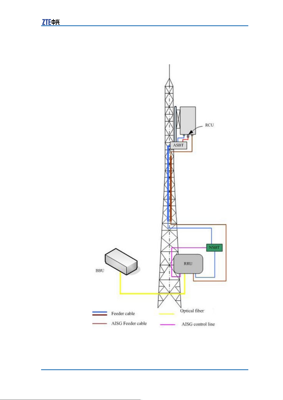
Chapter 5 Main Antenna Feeder System
adjustment
antenna (2)
FIGURE 62 ZXSDR BS8900 CONFIGURATION
ADJUSTMENT ANTENNA (2)
WITH
ELECTRONIC
Confidential and Proprietary Information of ZTE CORPORATION 73
Page 82
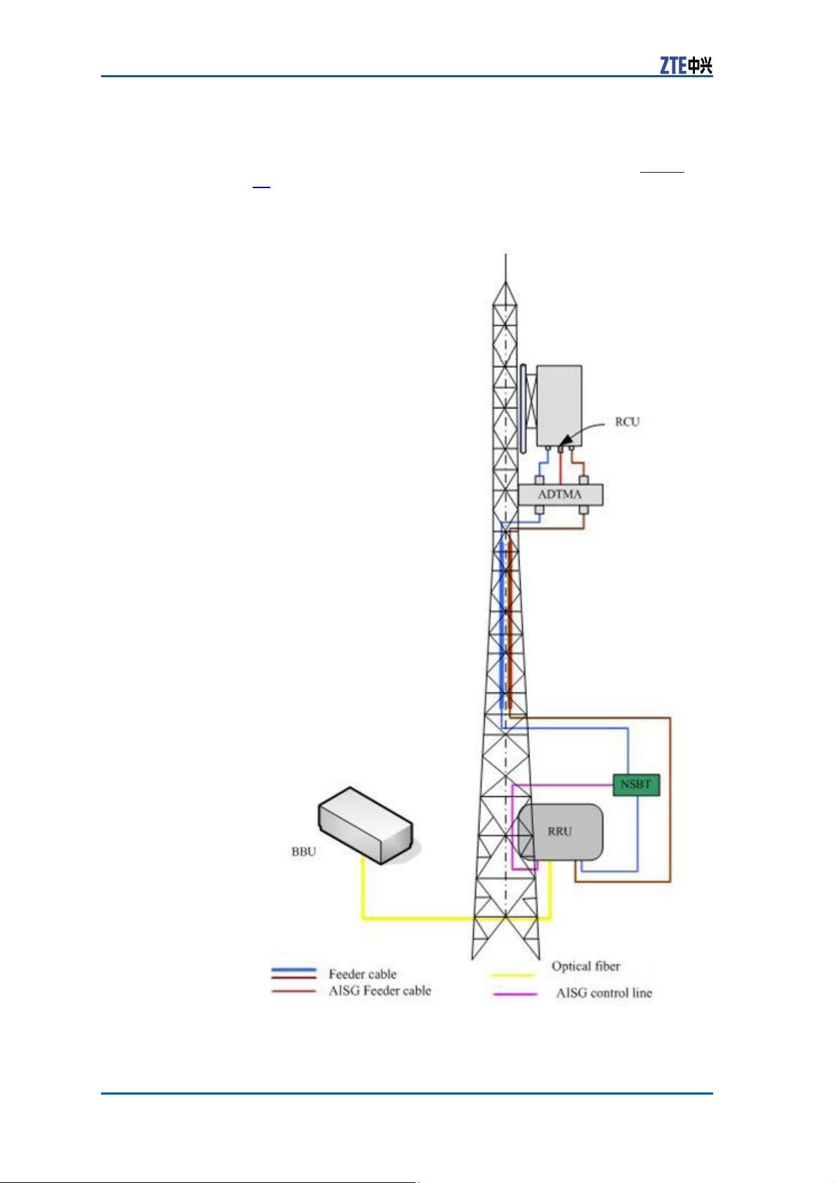
ZXSDR BS8900 Hardware Manual
configuration
with
electronic
adjustment
antenna , AISG
dual
ZXSDR
BS8900
power
amplifier
In this configuration, generally ZXSDR BS8900 is installed near
the top of the tower. ZXSDR BS8900 is connected to the
antenna by 5/4″or 7/8″feeder is adopted, as shown in Figure
63.
FIGURE 63 ZXSDR BS8900 CONFIGURATION
ADJUSTMENT ANTENNA. AISG DUAL
WITH
P
OWER
AMPLIFIER
ELECTRONIC
74 Confidential and Proprietary Information of ZTE CORPORATION
Page 83

Chapter 5 Main Antenna Feeder System
Antenna
The ZXSDR BS8900 antenna feeder system adopts common
antenna or electrical antenna. For the electrical antenna, you can
adjust the lever to control the embedded adjuster and thus to tune
the downtilt angle of the antenna. The tilt reflects the direction
from which the antenna receives the strongest signals. The tilt of
the uni-directional antenna can be tuned mechanically, and electrical tilt is used to tune the omni-directional antenna.
The principle of the electrical tilt is as follows:
The
adjustment
the maximum vertical and horizontal components and alters synthesized field strength, thus making the vertical pattern of the
antenna declining. Because the antenna field strength increases
or decreases simultaneously in all directions, which ensures that
the antenna pattern hardly varies with the tilt. This diminishes the
coverage of the main lobe and ensures that no interference occurs
when the coverage of the whole pattern decreases in its service
area.
Feeder
of the phase of the antenna array vibrator changes
Structure
The
feeder
the antenna and the ZXSDR BS8900 . There are many types of
feeder cables such as 1/2 inch and 7/8 inch feeder cable.
When the distance between the ZXSDR BS8900 cabinet and
antenna is less, then 1/2 inch feeder cable is used. In this case,
ZXSDR BS8900 cabinet is directly connected to the 1/2 inch
feeder and 1/2 inch feeder cable is connected to antenna.
When the distance between theZXSDR BS8900 cabinet and
antenna is more, then 7/8 inch feeder cable is used. In this case,
ZXSDR BS8900 cabinet is first connected to the jumper, then
jumper is connected to 7/8 inch feeder cable, and 7/8 inch feeder
cable is again connected to jumper and lastly jumper is connected
to antenna.
The antenna may have N type or DIN type interface. The feeder
is adapted to female and male N connectors. Usually both ends
of the delivered feeder are male N connector to facilitate on-site
installation.
is used to receive and transmit radio RF
Confidential and Proprietary Information of ZTE CORPORATION 75
signals
between
Page 84

ZXSDR BS8900 Hardware Manual
76 Confidential and Proprietary Information of ZTE CORPORATION
This page is intentionally blank.
Page 85

A
p p e n d i x A
Outdoor BBU+RSU
Cabinet
Table of Contents
Cabinet
Modules ...........................................................................84
External
Cabinet
............................................................................77
Cables ...............................................................
116
Outdoor BBU+RSU Cabinet
The equipment is an outdoor micro base station with powder coating (light gray, orange).
The outdoor BBU+RSU cabinet consists of an outdoor BBU cabinet
and an outdoor RSU cabinet that stand side by side. In a top-down
sequence the cabinet comprises a cover, an outdoor BBU+RRU
cabinet and a base (optional).
The cabinet is made of steel plates and profiles and the overall
MTBF is more than 100000hr.
The components and parts are made of environmental protection
materials without lead and can be recycled.
Cabinet
Technique
Figure 64 shows the appearance of the outdoor BBU+RSU cabinet.
Confidential and Proprietary Information of ZTE CORPORATION 77
Feature
Outer Structure
Page 86
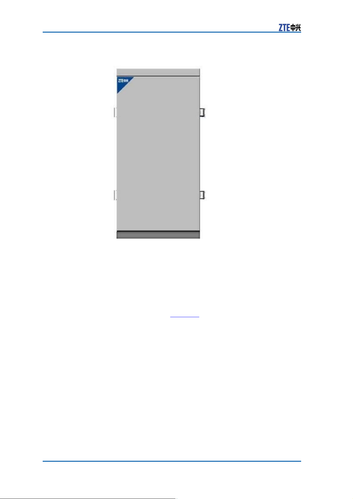
ZXSDR BS8900 Hardware Manual
FIGURE 64 CABINET
A
PPEARANCE
The dimensions of the cabinet are:
�
Without cover: 320 mm (W) × 600 mm (H) × 480 mm (D)
�
With cover: 320 mm (W) × 630 mm (H) × 480 mm (D)
�
Outdoor BBU cabinet: 210 mm (W) × 600 mm (H) × 480 mm
(D)
�
Outdoor RSU cabinet: 110 mm (W) × 600 mm (H) × 480 mm
(D)
The cabinet contains an outdoor BBU cabinet and an outdoor RSU
cabinet, as shown in Figure 65.
78 Confidential and Proprietary Information of ZTE CORPORATION
Page 87
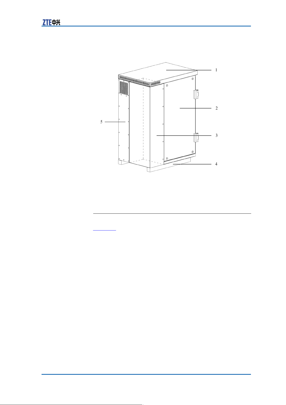
FIGURE 65 CABINET OUTER
S
TRUCTURE
Appendix A Outdoor BBU+RSU Cabinet
1. Cover
2. Outdoor BBU cabinet
3. Heat exchanger
4. Base (optional)
5. Outdoor RSU cabinet
Cabinet
Inner Structure
Figure 66 shows the inner structure of the outdoor BBU+RSU cab-
inet.
Confidential and Proprietary Information of ZTE CORPORATION 79
Page 88
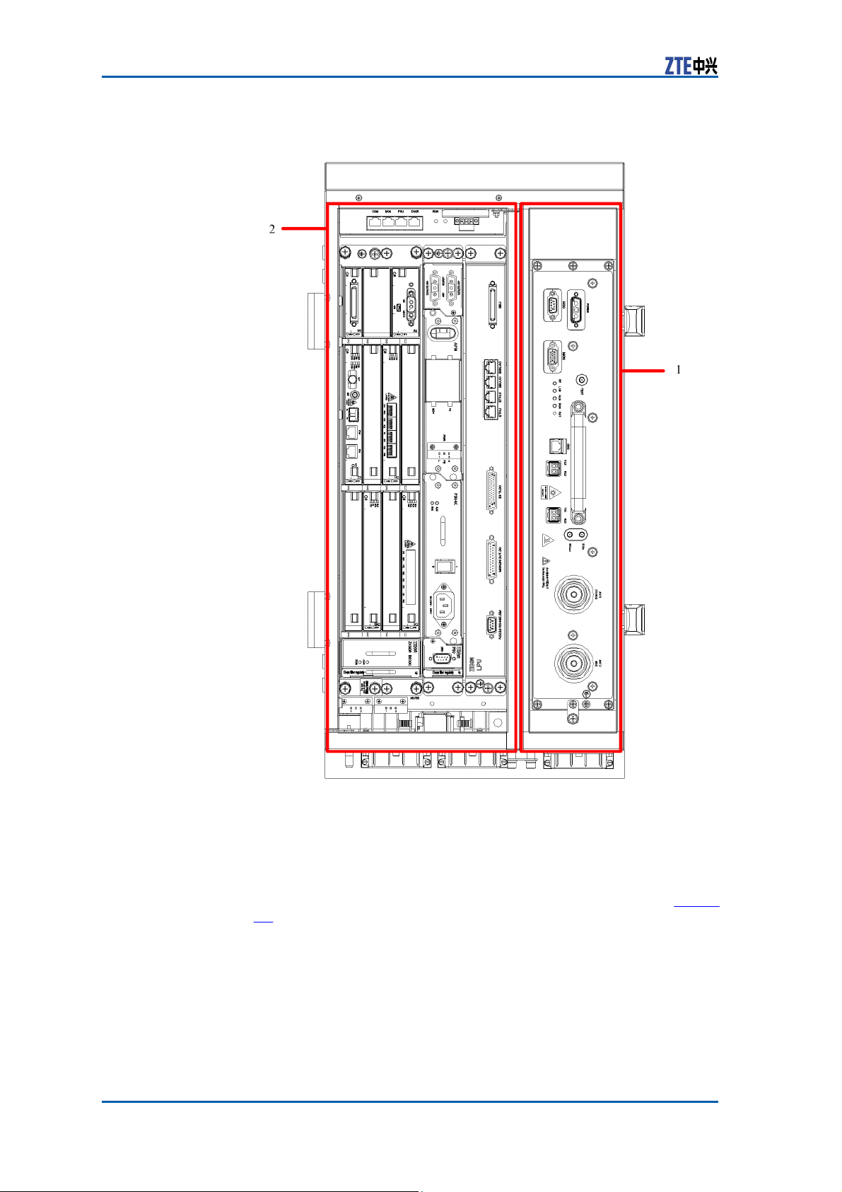
ZXSDR BS8900 Hardware Manual
FIGURE 66 CABINET INNER
S
TRUCTURE
1. Outdoor BBU cabinet 2. Outdoor RSU cabinet
Outdoor BBU Cabinet
The dimensions of the outdoor BBU cabinet with the heat exchanger are: 210 mm (W) × 600 mm (H) × 480 mm (D). Figure
80 Confidential and Proprietary Information of ZTE CORPORATION
67 shows the structure of the cabinet.
Page 89
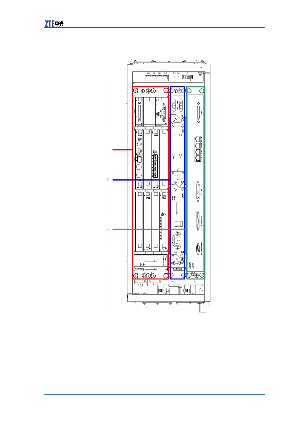
Appendix A Outdoor BBU+RSU Cabinet
FIGURE 67 OUTDOOR BBU CABINET
S
TRUCTU RE
1. BBU subrack
2. APM+PSU subrack/DPM+DDF sub-
rack
3. LPU subrack/transmission subrack/microwave subrack
Outdoor RSU Cabinet
The outdoor RSU cabinet and the outdoor BBU cabinet can be installed in the same
of the outdoor RSU cabinet are: 110 mm (W) × 600 mm (H) ×
480 mm (D).
Confidential and Proprietary Information of ZTE CORPORATION 81
cabinet
or in
different
cabinets. The dimensions
Page 90

ZXSDR BS8900 Hardware Manual
Figure 68 shows the structure of the RSU cabinet.
FIGURE 68 OUTDOOR RSU CABINET
S
TRUCTURE
82 Confidential and Proprietary Information of ZTE CORPORATION
Fan Box
The fan box is installed at the upside inlet to cool the outdoor BBU
cabinet.
Figure 69 shows the structure of the fan box.
Page 91
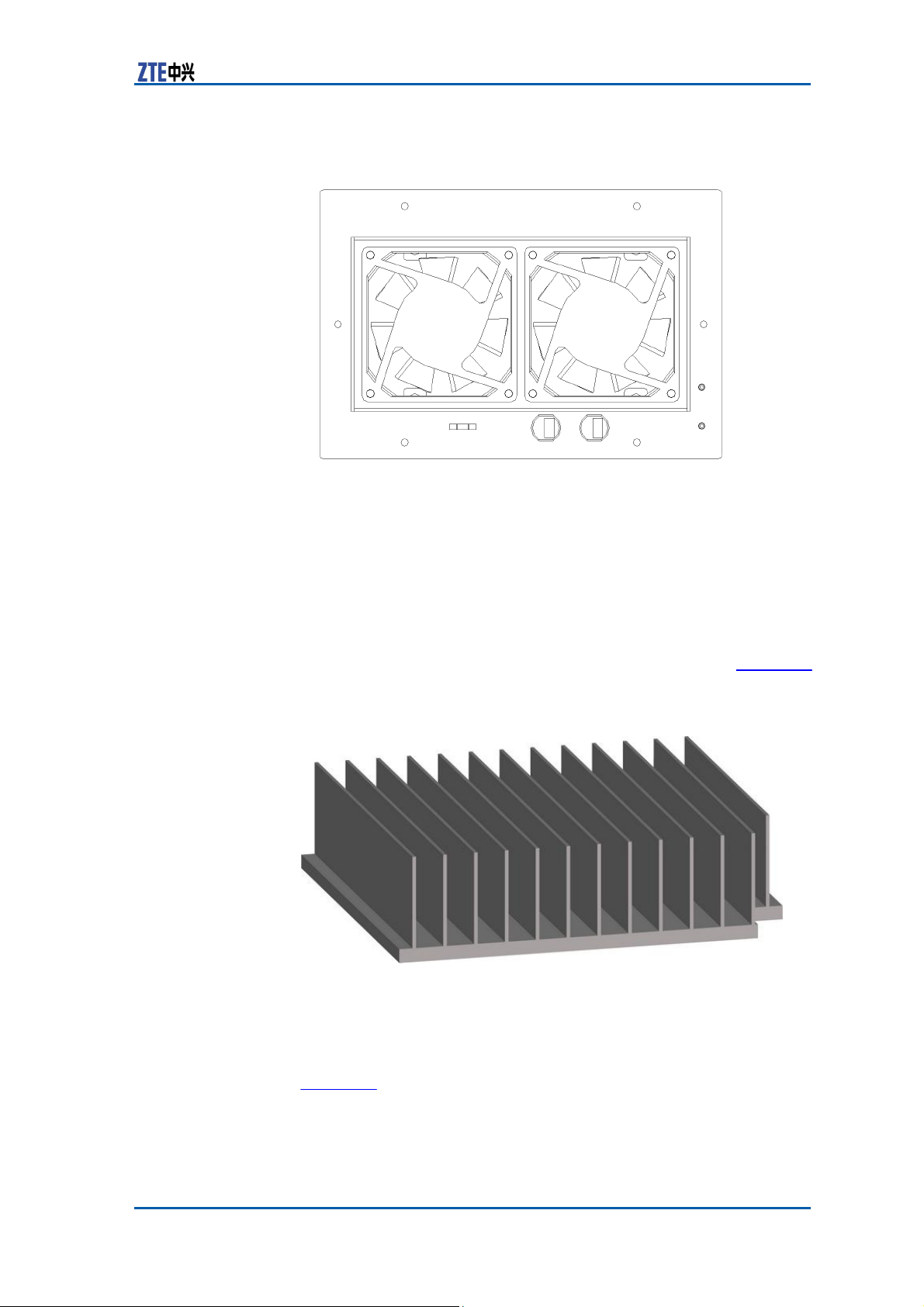
Appendix A Outdoor BBU+RSU Cabinet
FIGURE 69 FAN
B
OX
STRUCTURE
Heater
A heater is required when the outdoor BBU+RSU cabinet works
under –10 or lower.
The equipment can start in half an hour when the environment
temperature is -40 and the air temperature in the cabinet can
reach -10.
The dimensions of the heater are 160 mm ×175 mm. Figure 70
shows its structure.
FIGURE 70
H
EATER
STRUCTURE
Heat Exchanger
The outdoor BBU cabinet is cooled by a heat exchanger that is
located at the back of the case for back air exhaust, as shown in
Figure 71.
Confidential and Proprietary Information of ZTE CORPORATION 83
Page 92
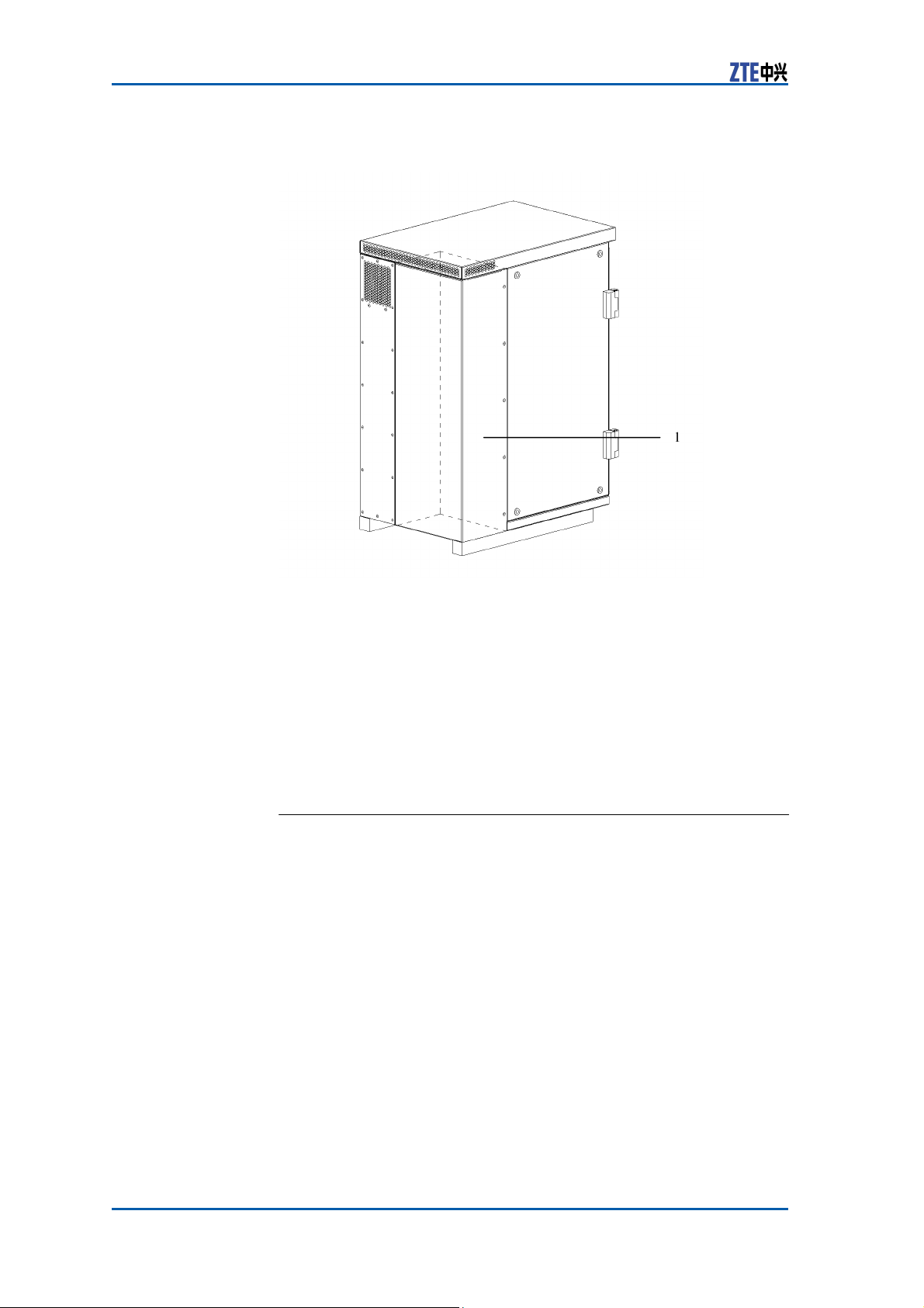
ZXSDR BS8900 Hardware Manual
FIGURE 71 HEAT EXCHANGER
P
OSITION
1. Heat exchanger position
The dimensions of the heat exchanger are: 480 mm × 165 mm ×
138 mm.
Modules
Control
Function CC module provides the following
�
Active/standby switchover
�
GPS system clock and RF reference clock
�
Abis interface function
�
Provision of the exchange plane for signaling stream and media
stream to implement GE Ethernet exchange function
�
One USB interface
�
Subrack management
�
Baseband modulation and demodulation
�
Provision of external clock extension interface (IEEE1588) and
communication extension interface (through the local mainte-
84 Confidential and Proprietary Information of ZTE CORPORATION
nance interface).
and Clock Module (CC)
functions:
Page 93
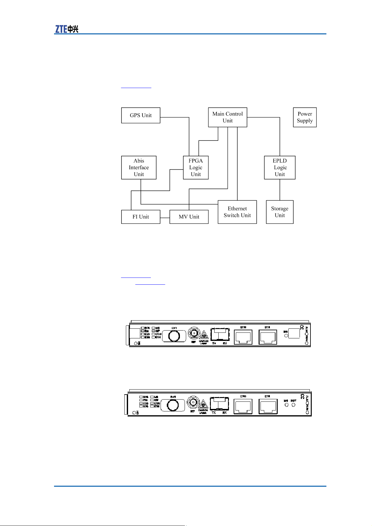
Appendix A Outdoor BBU+RSU Cabinet
Principle The CC module comprises main control unit, GPS unit, power sup-
ply unit, storage unit, Abis interface unit, FI unit, MV unit, Ethernet
exchange unit, FPGA logic unit and EPLD logic unit.
Figure 15 illustrates the principle of the CC module.
FIGURE 72 CC MODULE
P
RINCIPLE
Dimension The dimensions of CC module in mm are: 148.8 (H) x 19.0 (W)
181.5 (D).
x
The dimensions of CC module in inches are: 5 14/16 (H) x 12/16
Panel Figure 16 shows the appearance of the CC module panel with han-
(W) x 7 2/16 (D)
dle. Figure 17 shows the appearance of the CC module panel with-
out handle.
FIGURE 73 CC MODULE PANEL (WITH
H
ANDLE
)
FIGURE 74 CC MODULE PANEL (WITHOUT
H
ANDLE
)
Confidential and Proprietary Information of ZTE CORPORATION 85
Page 94
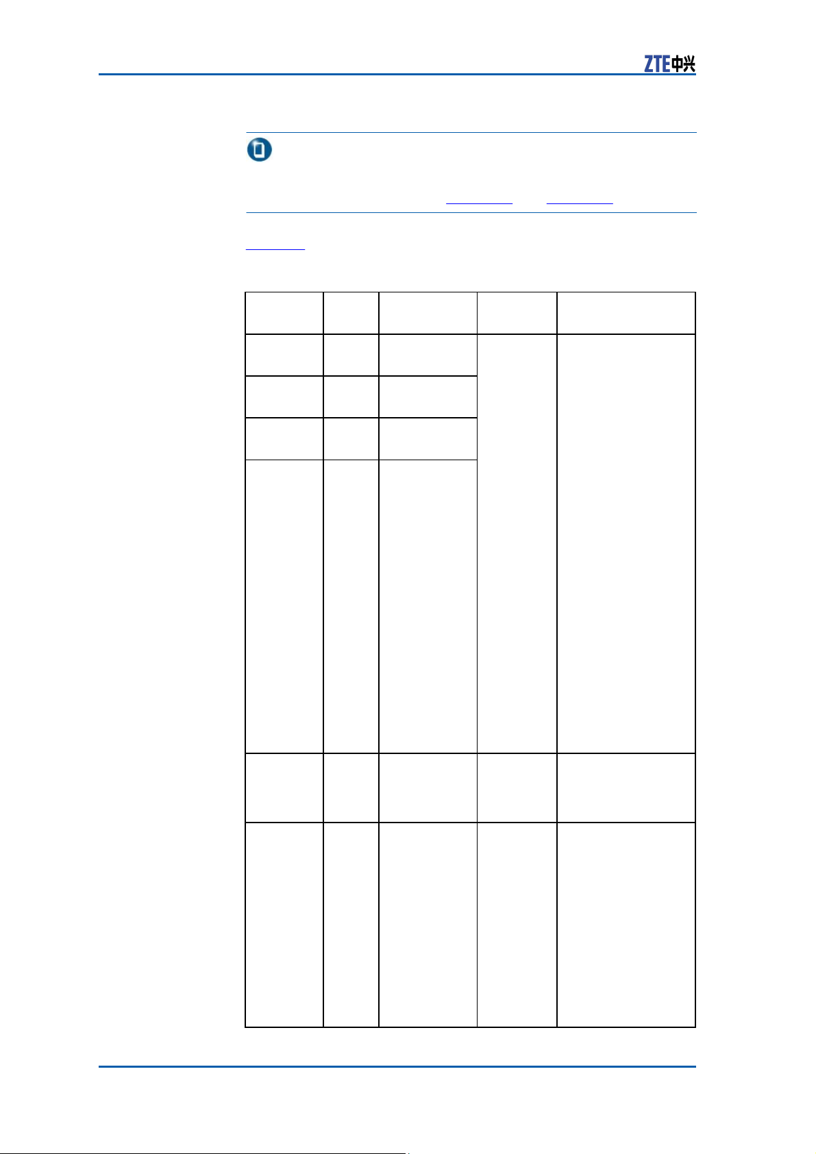
ZXSDR BS8900 Hardware Manual
Note:
Some buttons will be covered if the CC module panel is equipped
with handle, as illustrated in Figure 73 and Figure 74.
Indicator Table 10 describes the indicators on the CC module panel.
TABLE 43 CC MODULE PANEL INDICATOR
Indicator
Color Meaning
Name
E0S
Green
Indicator of
E1 link 1-4
E1S
Green
Indicator of
E1 link 5-8
E2S
Green
Indicator of
E1 link 9-12
E3S
Green
Indicator of
E1 link 13-16
MS
Green
Active/standby
indicator
REF
Green GPS antenna
indicator
86 Confidential and Proprietary Information of ZTE CORPORATION
D
ESCRIPTION
Flash
Status
Flash frequency:
8Hz
No flash
Six flash
types
Description
At most 4 flashes
per second, and on
for 0.125 seconds
and off for 0.125
seconds.
The first second:
One flash means
that link 0 is normal.
Off when the link is
unavailable.
The third second:
Two flashes
the
first link is
mean
normal. Off
when the
link is
unavailable.
The fifth second:
Three flashes mean
the second link
is normal. Off
when the link is
unavailable.
The seventh
second: Four
flashes mean the
third link is normal.
Off when the link is
unavailable.
Recycle again per 8
seconds.
On refers to
the
active board
Off refers to
the
standby board.
On when the
antenna feeder
is normal.
Off when the
antenna feeder
and the satellite are
being initialized.
Slow flash: On for
1.5 seconds and
off for 1.5 seconds
when
the
antenna
feeder is broken
Quick flash: On for
0.3 seconds and
Page 95
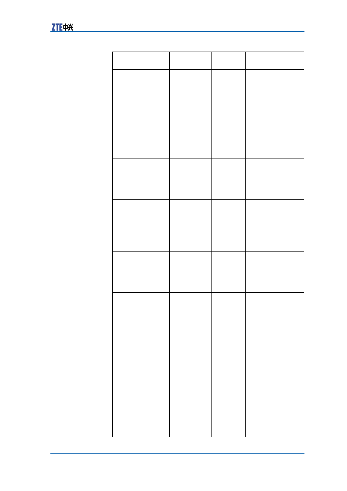
Appendix A Outdoor BBU+RSU Cabinet
Indicator
Color Meaning
Name
ETH0
ETH1
ALM
RUN
Green
Green
Red
Green
Abis interface
link
status
indicator
ETH1
network port
link status
indicator
Alarm
Indicator
Running
Indicator
Flash
Status
No flash,
controlled
by PHY
No flash,
controlled
by PHY
Processor
Control
Six flash
types
Description
off for
0.3 seconds
when the antenna
feeder is normal but
can
not
search the
satellite.
Slower flash: On
for 2.5 seconds and
off for 2.5 seconds
when the antenna is
short—circuited.
Quicker flash: On
for 70 ms and off
for 70 ms
when no
message is received
during initialization.
On when the Abis
interface physical
link is normal.
Off when the Abis
interface physical
link is broken.
On when the
ETH1 network port
physical link is
normal.
Off when the
ETH1 network port
physical link is
broken.
On when an alarm
occurs on the
module.
Off when no alarm
occurs on the
module.
On when the version
file begins to run to
request for the
logical address of
the module.
Slow flash: On for
1.5 seconds and off
for
1.5 seconds
when the module is
being powered on.
Normal flash: On
for 0.3 seconds and
off for 0.3 seconds
when the board
is under normal
operation.
Slow flash: On
for 2 seconds and
off for 2 seconds
when the board is
in active/standby
pre-changeover.
Slow flash: On
for 1 second and
Confidential and Proprietary Information of ZTE CORPORATION 87
Page 96
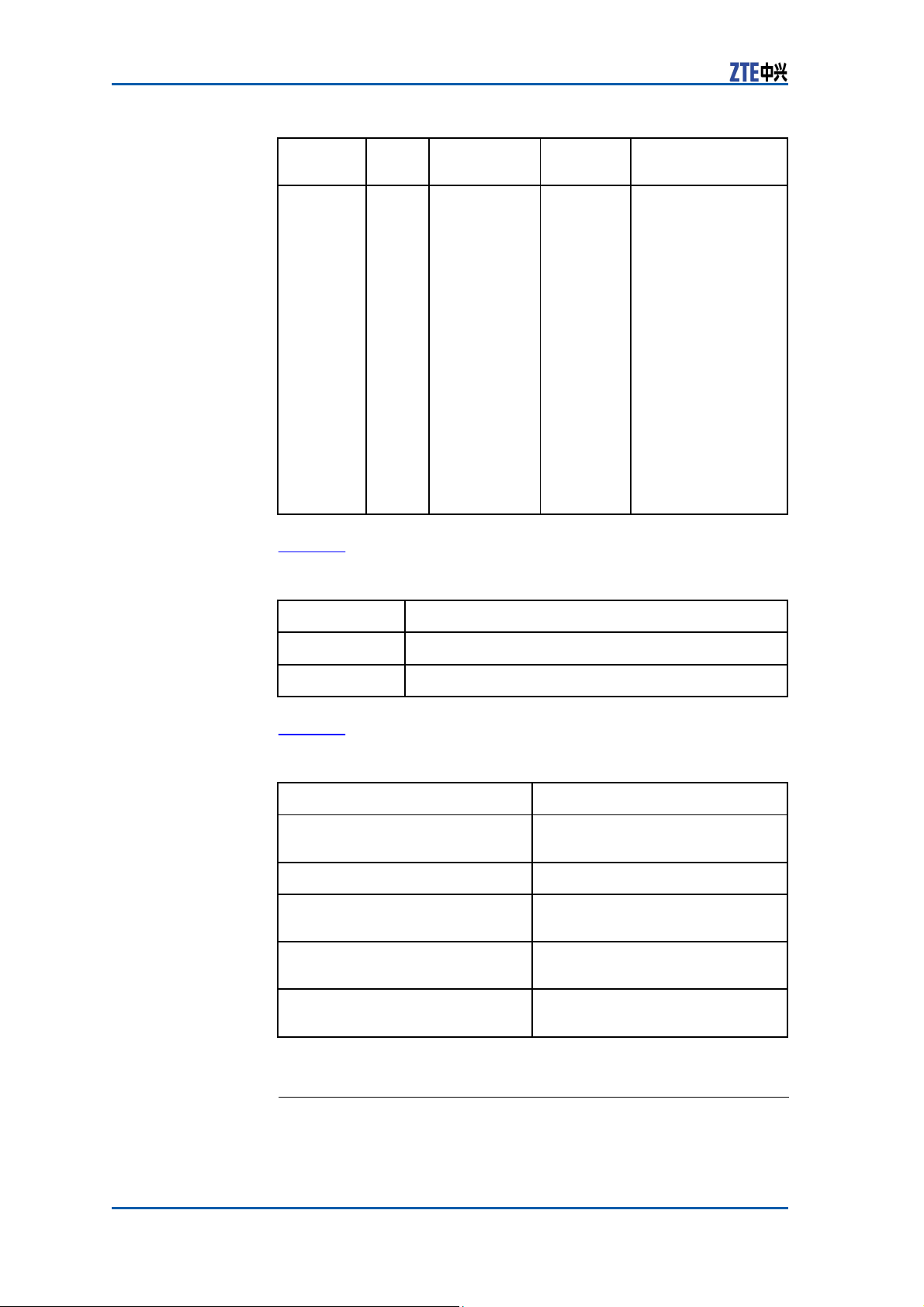
ZXSDR BS8900 Hardware Manual
Indicator
Color Meaning
Name
Flash
Status
Description
off for 1 second
when the board is
in active/standby
changeover.
Fast flash: On
for 70 ms and off
for 70 ms when
communication
between CC
board and OMP
is interrupted, or
communication
between active and
standby CCs/FSs
is
communication
between CH
CC is interrupted,
or communication
between FS and CC
is interrupted.
Button Table 11 describes the buttons on the panel of CC module.
Button
M/S
RST
Description
Active/standby switchover button
Reset button
TABLE 44 CC MODULE PANEL BUTTON
D
ESCRIPTION
Panel Interface Table 12 describes interfaces on the panel of CC module.
Interface Name
TABLE 45 CC MODULE PANEL INTERFACE
ETH0
ETH1
EXT
REF
TX/RX
D
ESCRIPTION
Description
GE/FE port connection between
BBU and BSC
Debugging or local maintenance
Connecting the external receiver
(RS485, PP1S and 2M
Connecting
GPS
externally
Connecting the optical interface
between BBU and BSC
interrupted, or
and
interfaces)
antenna
Channel
Processing Module (CH)
Function CH module performs the following functions:
88 Confidential and Proprietary Information of ZTE CORPORATION
Page 97
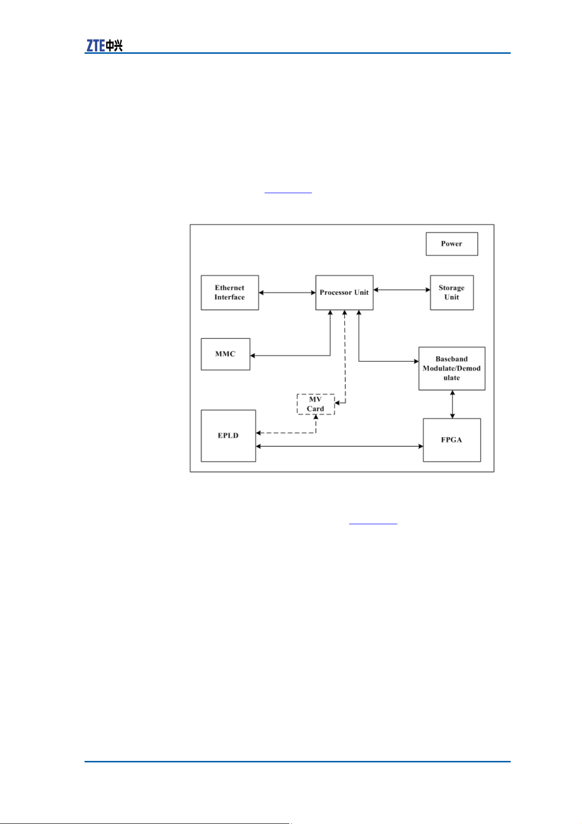
Appendix A Outdoor BBU+RSU Cabinet
�
The forward modulation and reverse demodulation of base-
band
�
CDMA key technologies, such as diversity technique, RAKE
receiving, softer-handoff and power control
�
Mixed insertion of CHV and CHD modules to support 1x and
Principle CHV module consists of processing unit, baseband modulation and
EV-DO service.
demodulation unit, FPGA unit, EPLD logic unit, power,
Ethernet
unit
and MMC unit. Figure 18 shows the principle of CHV module.
FIGURE 75 CHV
M
ODULE
PRINCIPLE
CHD module consists of multiplexing and de-multiplexing unit,
clock processing unit, ARM unit, DSP unit, modulation and demodulation unit and MPC unit. Figure 19 shows the principle of
CHD module.
Confidential and Proprietary Information of ZTE CORPORATION 89
Page 98
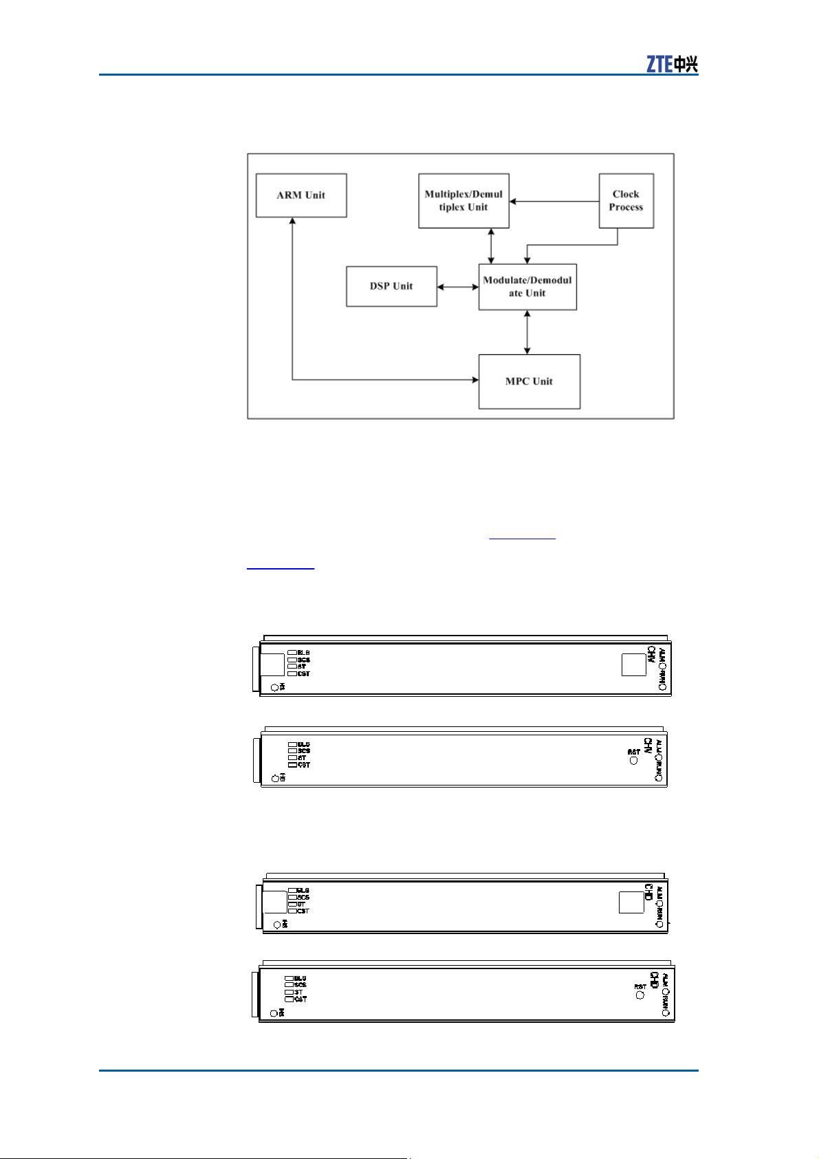
ZXSDR BS8900 Hardware Manual
FIGURE 76 CHD MODULE
P
RINCIPLE
Measurement The dimensions of CH module in mm are: 148.8 (H) x 19.0 (W) x
181.5 (D).
The dimensions of CH module in inches are: 5 14/16 (H) x 12/16
Panel CH is classified into CHV and CHD. Figure 20 shows the panel ap-
(W) x 7 2/16 (D).
pearance of CHV module with and without handle respectively.
Figure 21 shows the panel appearance of CHD module with and
without handle respectively.
FIGURE 77 CHV MODULE
P
ANEL
FIGURE 78 CHD MODULE
P
ANEL
90
Confidential and Proprietary Information of
ZTE CORPORATION
Page 99
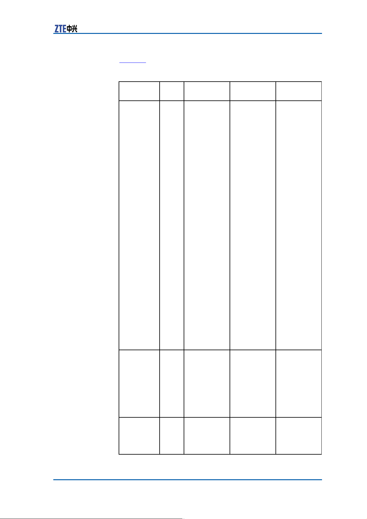
(50CHIP/10ms)
Appendix A Outdoor BBU+RSU Cabinet
Indicator Table 13 describes the indicators on the panel of CH
module.
Indicator
Color Meaning
TABLE 46 CH MODULE PANEL
I
NDICATOR
DESCRIPTION
Flash Status Description
Name
BLS
Green
Baseband link
(forward/reverse) running status
indicator
The flash
frequency
is
8Hz; it
indicates
the SERDES
receiving
status and
the forward
baseband
signal failure
while FS0/FS1
board
connects to
CH board.
SCS
Green
System clock
Three
statuses: On,
ST
Green
running status
indicator
Reservation
quick flash
and
Off.
Controlled by
CPU, EPLD
transparent
transmission
mode
Ordinal flash
on time, the
maximum
flash for four
times per second, 0.125s
On and 0.125s
Off
The first second: one flash
means communication
with FS0 is
normal and
Off means
communication is broken.
The forth second: two
flashes
mean
communication
with FS1
is normal
and
Off means
communication is broken.
Recycle
again
per 6 seconds.
If the
ward
for-
IO signal
check from
the channel
chip output is
wrong, it is
always
off.
If the 61.44M
clock or the
32CHIP clock
is wrong, it is
always
off.
On: the
system clock
running is
normal.
Quick flash:
10ms wrong,
0.125s On and
0.125s Off.
Off:
50CHIP
wrong.
-
Confidential and Proprietary Information of ZTE CORPORATION 91
Page 100
ZXSDR BS8900 Hardware Manual
Indicator
Name
CST
RUN
ALM
Button Table 14 describes the button on the CH Panel.
TABLE 47 CH BUTTON
Button Name
RST
Color Meaning
Green Communica-
tion status
indicator between CPU
and MMC
Flash Status Description
Controlled by
CPU, EPLD
transparent
transmission
mode
On: normal
communication between
CPU
and MMC
Off: failed
communication between
CPU and MMC.
Green
Running
Indicator
Four statuses:
5Hz flash, 1Hz
flash, On and
Off.
5 Hz flash:
the
board is
in power-up
procedure.
1 Hz flash:
the board
is normally
running.
On: the
version is
downloaded
successfully
and is being
started.
Off: the board
is abnormal.
Red Alarm
Indicator
Processor
Control
On:
the board
has alarm.
Off: the board
has no alarm.
D
ESCRIPTION
Description
Reset
Fabric
Switch Module (FS)
Functions The FS module provides the following functions:
�
In forward direction, performs the baseband data multiplexing
and framing and then transmit them to the remote RRU.
�
In reverse direction, performs deframing and demultiplexing
for received RRU remote data and then transmit them to the
baseband processing unit.
�
Supports six remote baseband fiber interfaces.
�
The logic unit implements all the functions except for optical
Principle The FS module comprises active/standby control unit, MCU0 unit,
92 Confidential and Proprietary Information of ZTE CORPORATION
interface processing.
MCU1 unit, EPLD logic, optical interface control unit, FPGA unit,
 Loading...