

Page 1

ZXMP M600 (V1.0)
Metro CWDM Equipment
Technical Manual
ZTE CORPORATION
Page 2

ZXMP M600 (V1.0)
Technical Manual
Manual Version 20050425-R1.0
Product Version V1.0
Copyright © ZTE Corporation
All rights reserved.
No part of this documentation may be excerpted, reproduced, translated, annotated or
duplicated, in any form or by any means without the prior written permission of ZTE
Corporation.
ZTE CORPORATION
ZTE Plaza, Keji Road South, Hi-Tech Industrial Park, Nanshan District, Shenzhen, P.R. China
Website: http://www.zte.com.cn
Postcode: 518057
Customer Support Center: (+86755) 26771900 800-9830-9830
Fax: (+86755) 26770801
Email: [email protected]
* * * *
S.N.: sjzl20041373
Page 3

FAX: +86-755-26770160
Suggestions and Feedback
To improve the quality of ZTE product documentation and offer better services to our customers, we hope
you can give us your suggestions and comments on our documentation and fax this form to
+86-755-26770160; or mail to “Marketing center 3rd floor ZTE Plaza, Keji Road South, Hi-Tech Industrial
Park, Nanshan District, Shenzhen, P. R. China”. Our postcode is 518057.
Document name Unitrans ZXMP M600 (V1.0) Metro CWDM Equipment Technical Manual
Product version V1.0 Document version 20050425-R1.0
Equipment installation time
Your information
Name Company
Postcode Company address
Telephone E-mail
Presentation: How is information presented? (Introductions, procedures, illustrations, others)
Good Fair Average Poor Bad
Your evaluation
of this
documentation
Your suggestions
for improvement
of this
documentation
Your other
suggestions on
ZTE product
documentation
Accessibility: Can you find the information you want? (Table of contents, Index, headings,
numbering, others)
Good Fair Average Poor Bad
Intelligibility: Can you understand it when you find it? (Language, vocabulary, readability, others)
Good Fair Average Poor Bad
Presentation:
Accessibility:
Intelligibility:
Page 4

Page 5

Preface
About This Manual
This manual is applicable to Unitrans ZXMP M600 (V1.0) Metro CWDM Equipment
(ZXMP M600 for short).
The ZXMP M600 is a wavelength division equipment belonging to the metropolitan
area optical network product series developed by ZTE. This equipment is capable of
transparently transmitting signals at various rates and services. It features high optical
transmission capacity and fully satisfies users’ requirements on networking and
management. Therefore, this equipment is applicable to various layers in
small-/medium-sized Metropolitan Area Network (MAN), the convergence layer and
access layer of a large-sized MAN.
The equipment has four accompanying manual, including:
Unitrans ZXMP M600 (V1.0) Metro CWDM Equipment Technical Manual
Unitrans ZXMP M600 (V1.0) Metro CWDM Equipment Hardware Manual
Unitrans ZXMP M600 (V1.0) Metro CWDM Equipment Installation Manual
Unitrans ZXMP M600 (V1.0) Metro CWDM Equipment Maintenance Manual
How to Use This Manual
Unitrans ZXMP M600 (V1.0) Metro CWDM Equipment Technical Manual deals
with the architecture, technical indices, system functions, configuration and networking
of the ZXMP M600. It enables users to get a comprehensive understanding of the
ZXMP M600 and serves as a basis for the users to read other relevant documents.
Chapter 1 System Overview briefs the background, applicable standards, system
structure and features of the ZXMP M600.
Chapter 2 Technical Indices describes various technical indices of the ZXMP-M600
in detail.
Page 6

Conventions
Chapter 3 System Functions deals with the functions of the ZXMP M600 and their
implementation, including the transmission function, Service multiplexing function and
protection function.
Chapter 4 System Configurations and Networking Modes introduces the
networking modes supported by the ZXMP M600, the system configuration
requirements and networking examples. It enables the users to understand the
networking capability and service providing capability of the equipment.
Appendix A Explanation of Terms provides a brief explanation to some terms
adopted to facilitate understanding the manual.
Appendix B Abbreviations summarizes the English abbreviations and terms in the
manual for readers’ reference.
1. Notational convention
Angular brackets “<and>” identify names of keys and buttons, and the
information typed by an operator from a terminal
Square brackets “[and]” indicate a man-machine interface, menu item, data list
or field name. The symbol “→” separates a multi-level menu, e.g., [File→
New→ Folder] indicates the [Folder] menu item under the [New] submenu of
the menu [File].
2. Keyboard Operation Convention
Format Description
Characters within
angular brackets
<Key 1+Key 2> Press Key 1 and Key 2 at the same time.
<Key 1, Key 2> Press Key1 first. Then release Key 1 and press Key 2
Indicate a key or button name, e.g., <Enter>, <Tab>, <Backspace>, and
<a>
Page 7
3. Mouse Operation Convention
Format Description
Click
Double-click
Right-click
Drag Refers to pressing and holding a mouse button and move the mouse
Refers to clicking the primary mouse button (usually the left mouse
button) once
Refers to quickly clicking the primary mouse button (usually the left
mouse button) twice
Refers to clicking the secondary mouse button (usually the right mouse
button) once.
4. Danger, Warning, Caution and Note Statements
Danger, Warning, Caution and Note statements are
used throughout this manual to emphasize important and critical information. You must
read these statements to help ensure safety and to prevent product damage. The
statements are defined below.
Danger:
Indicates an imminently hazardous situation which, if not avoided, will result in death
or serious injury. This signal word is to be limited to the most extreme situations.
Warning:
Indicates a potentially hazardous situation that, if not avoided, could result in death or
serious injury.
Caution:
Indicates a potentially hazardous situation that, if not avoided, could result in minor or
moderate injury. It may also be used to alert against unsafe practices.
Page 8

Note:
A Note statement is used to notify people of installation, operation, or maintenance
information that is important, but not hazard-related.
Tips:
Indicates a suggestion or hint to make things easier or more productive for the reader
Statement: The actual product may differ from what is described in this
manual due to frequent update of ZTE products and fast development of
technologies. Please contact the local ZTE office for the latest updating
information of the product.
Page 9

Contents
1 System Overview.....................................................................................................................................1-1
1.1 System Background .......................................................................................................................1-1
1.1.1 MAN ...................................................................................................................................1-1
1.1.2 Wavelength Division Multiplexing Technique....................................................................1-4
1.2 System Structure ............................................................................................................................ 1-6
1.2.1 Structure of Hardware System ............................................................................................1-6
1.2.2 Structure of Network Management Software System......................................................... 1-9
1.3 System Features ...........................................................................................................................1-12
1.4 Applicable Standards/Recommendations.....................................................................................1-14
2 Technical Indices .....................................................................................................................................2-1
2.1 System Indices ...............................................................................................................................2-1
2.2 Structure Indices.............................................................................................................................2-2
2.3 Power Indices................................................................................................................................. 2-3
2.3.1 Voltage Requirements .........................................................................................................2-3
2.3.2 Power Consumption Requirements.....................................................................................2-3
2.4 Environment Requirements............................................................................................................ 2-4
2.4.1 Grounding Requirements.................................................................................................... 2-4
2.4.2 Temperature and Humidity Requirements...........................................................................2-4
2.4.3 Cleanness Requirements .....................................................................................................2-5
2.4.4 Dustproof and Anti-corrosion Requirements ......................................................................2-5
2.5 Working Wavelengths ....................................................................................................................2-5
2.6 Reliability.......................................................................................................................................2-6
-i-
Page 10

2.7 Optical safety and electrical safety ................................................................................................ 2-6
2.8 Indices of System Component Parts .............................................................................................. 2-7
2.8.1 Performance Indices of OMD............................................................................................. 2-7
2.8.2 Performance Indices of OAD Units.................................................................................... 2-8
2.8.3 OTU Interface Indices ...................................................................................................... 2-10
2.8.4 Performance Indices of Optical Supervisor Channel........................................................ 2-13
2.8.5 SRM42 Interface Indices .................................................................................................. 2-13
3 System Function...................................................................................................................................... 3-1
3.1 Line Transmission Function .......................................................................................................... 3-1
3.2 Service Functions........................................................................................................................... 3-2
3.2.1 Service Access Function..................................................................................................... 3-2
3.2.2 Service Convergence Function ........................................................................................... 3-2
3.3 Communication and Monitoring Functions................................................................................... 3-3
3.3.1 Communication between EMS and Access Point............................................................... 3-3
3.3.2 Communication between Nodes ......................................................................................... 3-5
3.3.3 Intra-node Communication and Monitoring ....................................................................... 3-6
3.4 Power Input and Output Functions ................................................................................................ 3-7
3.5 Grounding Function....................................................................................................................... 3-7
3.6 Alarm Output Function.................................................................................................................. 3-7
3.7 Protection Function........................................................................................................................ 3-8
3.7.1 Ring Network Protection .................................................................................................... 3-8
4 System Configurations and Networking Modes................................................................................... 4-1
4.1 System Configuration.................................................................................................................... 4-1
4.1.1 Board Slot Resources.......................................................................................................... 4-1
4.1.2 Metro Optical Terminal Equipment (OTM)........................................................................ 4-2
-ii-
Page 11

4.1.3 Metro OADM Equipment (OADM) ...................................................................................4-2
4.2 Networking Mode .......................................................................................................................... 4-2
4.2.1 Point-to-point Networking ..................................................................................................4-2
4.2.2 Chain Networking...............................................................................................................4-2
4.2.3 Ring Networking.................................................................................................................4-2
4.2.4 Ring-to-chain Networking ..................................................................................................4-2
4.3 Configuration Example..................................................................................................................4-2
4.3.1 Configuration Implementation ............................................................................................ 4-2
4.3.2 Application Features............................................................................................................4-2
Appendix A Term Description..................................................................................................................A-2
Appendix B Abbreviations ....................................................................................................................... B-2
-iii-
Page 12

Page 13

List of Figures
Fig. 1.1-1 Basic Structure of MAN...................................................................................................1-3
Fig. 1.2-1 Functional Structure of the ZXMP M600 Equipment ......................................................1-6
Fig. 1.2-2 Functional Structure of OTM Equipment.........................................................................1-8
Fig. 1.2-3 Functional Structure of OADM Equipment .....................................................................1-8
Fig. 1.2-4 Structure of the Network Management Software System.................................................1-9
Fig. 2.8-1 Optical Interfaces of OMD Units .....................................................................................2-7
Fig. 2.8-2 Optical Interfaces of OAD Units......................................................................................2-8
Fig. 3.3-1 Connection between the Access Point and the EMS (through an Ethernet interface)...... 3-3
Fig. 3.3-2 Connection with the EMS Through SDH Equipment ......................................................3-4
Fig. 3.3-3 Connection with the EMS through RS232 .......................................................................3-5
Fig. 3.3-4 Intra-node Communication and Monitoring Channel.......................................................3-6
Fig. 3.7-1 1+1 Protection of Optical Channel on a Ring Network.................................................... 3-8
Fig. 4.1-1 Slot Distribution in the CWU Shelf..................................................................................4-1
Fig. 4.1-2 Slot Distribution in the SMU Shelf ..................................................................................4-2
Fig. 4.1-3 Board Configuration of OTM Equipment (which adds/drops 8 wavelengths).................4-2
Fig. 4.1-4 Fiber Connection of OTM Equipment (1310nm monitoring channel)............................. 4-2
Fig. 4.1-5 Board Configuration of OADM Equipment (which adds/drops 3 wavelengths)..............4-2
Fig. 4.1-6 Fiber Connections of OADM (which adds/drops 3 wavelengths)....................................4-2
Fig. 4.2-1 Application of Point-to-point Networking........................................................................4-2
Fig. 4.2-2 Application of Chain Networking ....................................................................................4-2
Fig. 4.2-3 Application of Ring Networking ...................................................................................... 4-2
Fig. 4.2-4 Application of Ring-to-chain Networking........................................................................4-2
-i-
Page 14

Fig. 4.3-1 Networking in a Typical Configuration Example ............................................................ 4-2
Fig. 4.3-2 Service Requirements....................................................................................................... 4-2
Fig. A.9-1 Optical Transmission Over Interface Made of Uneven Media....................................... A-2
Fig. A.9-2 Optical Dispersion Over a Fiber..................................................................................... A-2
-ii-
Page 15

List of Tables
Table 2.2-1 Outline Dimensions and Weight Indices of the ZXMP M600 Component Parts...........2-2
Table 2.3-1 Power Consumption Indices of the ZXMP M600 Boards/Units....................................2-3
Table 2.4-1 Temperature and Humidity Requirements .....................................................................2-5
Table 2.5-1 Wavelength Distribution of the ZXMP M600 Equipment (with ordinary fibers adopted)
.............................................................................................................................................................2-6
Table 2.8-1 Performance Indices of OMD........................................................................................ 2-8
Table 2.8-2 Performance Indices of OAD Units ............................................................................... 2-9
Table 2.8-3 Indices of the Line End Optical Transmitting Port ......................................................2-10
Table 2.8-4 Indices of the Line End Optical Receiving Port...........................................................2-11
Table 2.8-5 Indices of Client Optical Transceiving Module ...........................................................2-12
Table 2.8-6 Major Performance Indices of Optical Monitoring Channel........................................2-13
Table 2.8-7 Indices of Client Optical Transceiving Module ...........................................................2-14
Table 4.1-1 Relation between the Boards and Slots in the CWU Shelf ............................................4-1
Table 4.1-2 Relation between the Boards and Slots in the SMU Shelf.............................................4-2
Table 4.3-1 Equipment Configuration...............................................................................................4-2
-i-
Page 16

Page 17

1 System Overview
This chapter introduces the background, architecture, system features and applicable
standards/recommendations. It aims at laying a basis for readers to understand the
equipment.
1.1 System Background
The ZXMP M600 is the metro CDWM system developed by ZTE. It features large
optical transmission capacity and can implement transparent transmission of various
services at multiple rates. It can be applied to the convergence and access layers of
large MANs as well as various layers of middle- and small-sized MANs.
In the following, the Metropolitan Area Network (MAN) and Wavelength Division
Multiplexing (WDM) will be introduced briefly.
1.1.1 MAN
1.1.1.1 Concept
As data services such as IP and Ethernet services develop rapidly in recent years, a data
network that can provide wide coverage, high-speed bandwidth and convenient
services is required for providing services such as Internet access, IP-based virtual
private network, IP phone, multimedia application and e-commerce. Meanwhile, as a
metropolis features prosperous economy, dense population, compact coverage area and
frequent information exchange, the information-oriented construction keeps developing
rapidly. Thus, the requirements on MAN also becomes higher and higher.
Generally a MAN is considered as a broadband network that has a unified protocol and
connects government departments, educational and scientific institutions, companies
and home users. It provides data services as well as integrated multimedia services
such as packet voice, graphic and video services, and covers local public networks in
metropolitan and suburb areas.
Based on the statistics and packet technology, the MAN boasts of a clear network
structure, perfect expandability and high reliability. The products and technologies
1-1
Page 18

ZXMP M600 (V1.0) Technical Manual
adopted in it are widely used for commercial purposes, while the user and service
management is flexibly and convenient. The MAN features broadband capacity and
rate, efficient transmission of information and diversified access methods. It obtains the
contents locally, offers user-defined access, provides characteristic services and can
deploy new services quickly. In addition, its capacity can be expanded flexibly and its
upgrade and development can be predicted.
1.1.1.2 Basic Structure
The MAN can either be divided vertically or horizontally:
1. Vertical division
The MAN can be vertically divided into the access layer, convergence layer and
core layer.
The access layer accesses different types of subscribers such as routers and LAN.
The convergence layer converges sporadic access points, implements data
multiplexing, transmitting and switching, and provides traffic control and user
management functions. It includes Multi-Service Transmit Platform (MSTP) and
Metro OADM. The core layer implements high-speed information exchange on
the whole network as well as interconnection between backbone networks. It
generally consists of OADM equipment.
1-2
Page 19
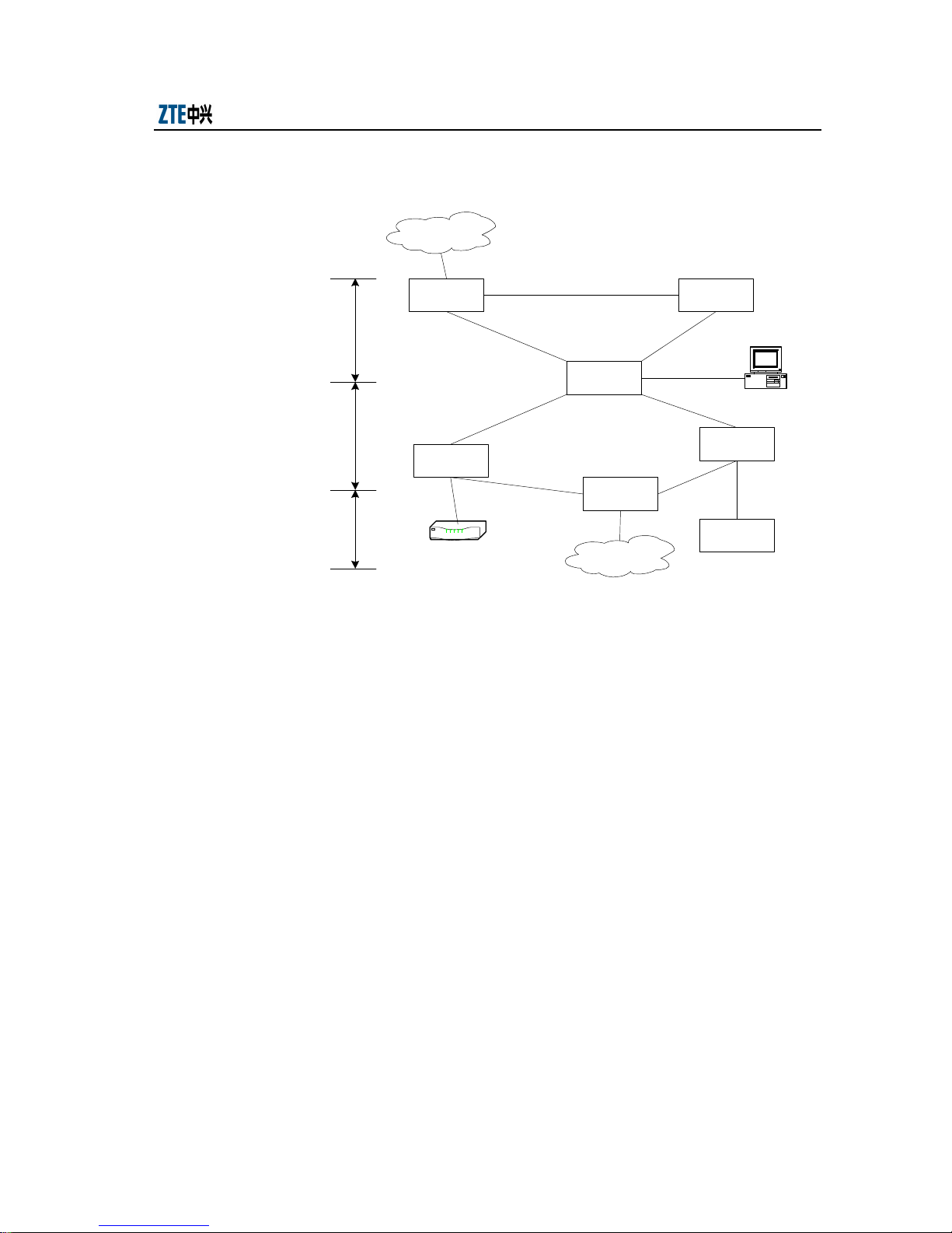
Chapter 1 System Overview
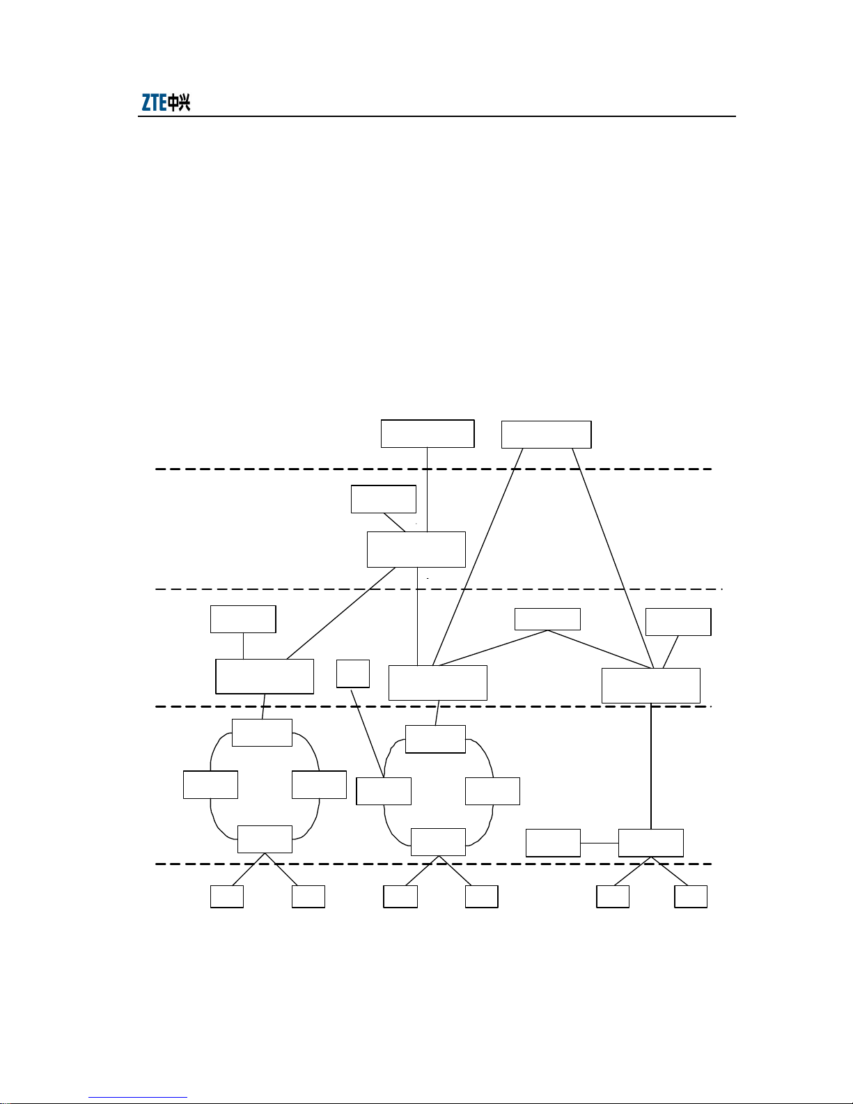
Fig. 1.1-1 shows the basic structure of a MAN.
Backbone layer
MOADMMOADM
Core layer
MOADM
Convergence
layer
MSTP
MSTP
Access layer
Router
MSTP: multi-service transmit platform OADM: metro OADM
Fig. 1.1-1 Basic Structure of MAN
LAN
MSTP
ATM
2. Horizontal division
A MAN can also be horizontally divided into the service layer and transmission
layer.
The service layer can implement multiple services such as narrowband voice
service, Internet service, remote calculation and transaction processing,
e-commerce, video conference, multimedia integrated information service,
remote communication and control through computer and leased line service. It
consists of various ATM and IP devices. The transmission layer indicates the
metro optical network that carries the services at the service layer. It provides an
efficient and a unified transmission platform that features large capacity and low
cost and consists of WDM and SDH devices.
Service and
management
center
1-3
Page 20

ZXMP M600 (V1.0) Technical Manual
1.1.1.3 Features of Metro Optical Network
1. Large service access capacity
The rapid development of MAN service causes the acute increase in the demand
for bandwidth. This demand can only be met by large-capacity metro optical
network. Thus, the core layer of the metro optical network should have large
service access capacity and should be capable of continuous upgrading.
2. Multi-service convergence and transparent transmission
To make full use of the existing network resources, the core layer should be able
to converge various low-rate services and encapsulate services of different rates
and with different protocols into a single wavelength. This helps save the
wavelength resources and economize network construction. On the other hand,
to avoid extra overhead due to protocol conversion and frame format matching
and to make full use of the bandwidth resources, the core layer is also required
to transmit the carried services in the original mode.
3. High reliability and powerful network protection capability
The network security and reliability guarantee normal service transmission.
Thus, redundancy protection measures should be provided for the hardware on
the equipment. Besides, channel protection and multiplex section protection
should also be provided at various levels on the network.
4. Low networking cost
1.1.2 Wavelength Division Multiplexing Technique
As MAN services become increasingly abundant, the requirement on the MAN
capacity becomes higher and higher. As a result, the multi-service broadband MAN
gradually becomes a hotspot in the telecom and network construction. To use the
existent optical fiber resources to increase the bandwidth capacity, the Wavelength
Division Multiplexing (WDM) technique is adopted in the MAN.
WDM can be divided into Dense Wavelength Division Multiplexing (DWDM)
technique and Coarse Wavelength Division Multiplexing technique.
1.1.2.1 DWDM Technique
The DWDM technique adopts an Erbium Doped Fiber Amplifier (EDFA), a high
wavelength stability laser and dense wavelength division multiplexing/ demultiplexing
1-4
Page 21

Chapter 1 System Overview
equipment to transmit optical signal service and implement balanced management of
optical power on the whole line. In the DWDM system, the selection of wavelength
and the frequency intervals should conform to ITU-T Recommendation G.692.
The working wavelength range of the DWDM system is 1528.77nm~1560.61nm and
the corresponding working frequency range is 196.1THz~192.1THz.
The channel interval of the system is a multiple of 100GHz (about 0.8nm). The smaller
the channel interval is, the higher the resolution of the optical demultiplexer should be.
The channel interval commonly used at present is either 200GHz (about 1.6nm) or
100GHz (about 0.8nm).
While saving the cost of the electrical relay, EDFA technique adopted in the DWDM
equipment presents much higher requirements on the wavelength stability, dispersion
tolerance and chirp performance of the laser.
Therefore, if the DWDM equipment that suitable for long distance transmission is used
in a MAN that features short transmission distance and diversified service interfaces,
the network construction cost will greatly increase.
1.1.2.2 CWDM Technique
The CWDM technique is developed to improve the utility of optical fibers on the MAN,
to provide multiple service interfaces and to cut the network construction cost at the
same time.
The working principle of CWDM is similar to that of DWDM. At the transmitting end
of the link, an optical multiplexer is used to multiplex the wavelengths transmitted in
different fibers into one fiber for transmission, while at the receiving end, a
demultiplexer is used to recover the original wavelengths from the combined
wavelength.
The wavelength selection and channel interval of the CWDM conforms to ITU-T
Recommendation G694.2. The wavelength interval is 20 nm, while the working
wavelength range is determined by the adopted fiber type. If an ordinary fiber type
G.652 A&B is adopted, then the working wavelength range is 1470nm~1610 nm; if
full-wave fibers, that is, G.652 C&D fibers are adopted, then the working wavelength
range is 1270 nm~1610 nm.
1-5
Page 22
ZXMP M600 (V1.0) Technical Manual
The CWDM system adopts uncooled laser and multiplexer/demultiplexer. Compared to
DWDM, it boasts shorter transmission distance and lower cost and is suitable for the
construction of MAN.
1.2 System Structure
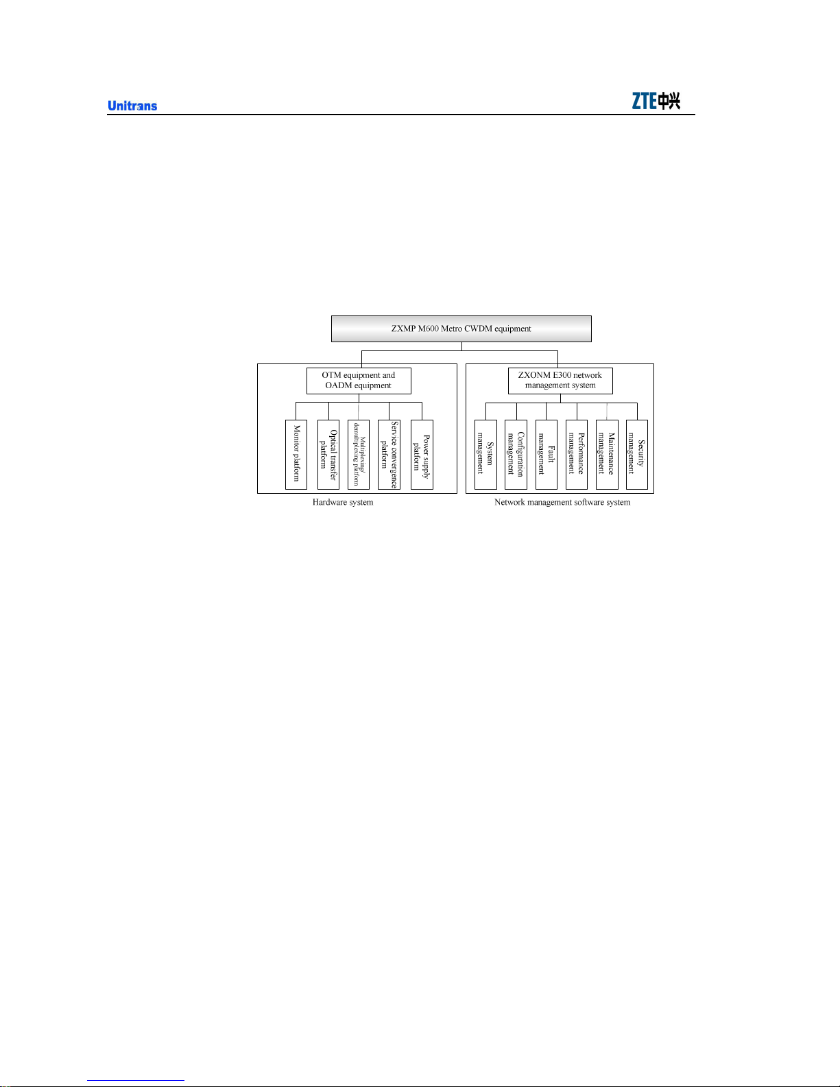
The structure of the ZXMP M600 equipment is shown in Fig. 1.2-1.
Fig. 1.2-1 Functional Structure of the ZXMP M600 Equipment
The ZXMP M600 equipment can be divided into the hardware system and network
management software system. The two systems are independent of each other but will
also work together.
1.2.1 Structure of Hardware System
1.2.1.1 Platform Functions
The hardware system of the ZXMP M600 includes an optical transfer platform, service
convergence system, multiplexing/demultiplexing platform, monitor platform and
power supply platform.
1. Optical transfer platform
It adopts the optical/ electrical/ optical conversion mode to implement
wavelength conversion of service signals and line signals.
The service signals include multi-service signals with a rate lower than 2.5Gbit/s
and with the maximum rate being 2.5Gbit/s.
1-6
Page 23

Chapter 1 System Overview
The line signals meet the requirements specified in ITU-T recommendation
G.694.2.
2. Service convergence platform
It converges multiple channels of low rate signals into one wavelength for
transmission and implements the reserve process.
The low rate signals include standard STM-1, STM-4 signals with the maximum
rate being 2.5Gbit/s on the line.
3. Multiplexing/demultiplexing platform
It includes a multiplexing part and a demultiplexing part.
1) Multiplexing part: It couples multiple channels of optical signals with different
wavelengths from the optical transfer platform and service convergence platform
to a piece of optical fiber for transmission.
2) Demultiplexing part: It divides the multiplexing optical signals from the line
side according to their different wavelengths and sends them to different optical
transfer platform and service convergence platform.
4. Monitor platform
1) Collecting, processing and reporting the configuration, alarm and performance
information of the various platforms
2) Receiving the command from the EMS and transferring it to the destination
board
3) Using a specified monitoring optical channel to transparently transmit the
network management information. The wavelength of the monitoring channel
can be either 1310nm or 1510nm.
5. Power supply platform
It converts in DC input into +5V or -48V DC power to provide power for
various platforms.
Options –48V, +24V and –60V are available for DC power supply, and 1+1
warm backup are practicable.
1-7
Page 24
ZXMP M600 (V1.0) Technical Manual
1.2.1.2 System Configuration
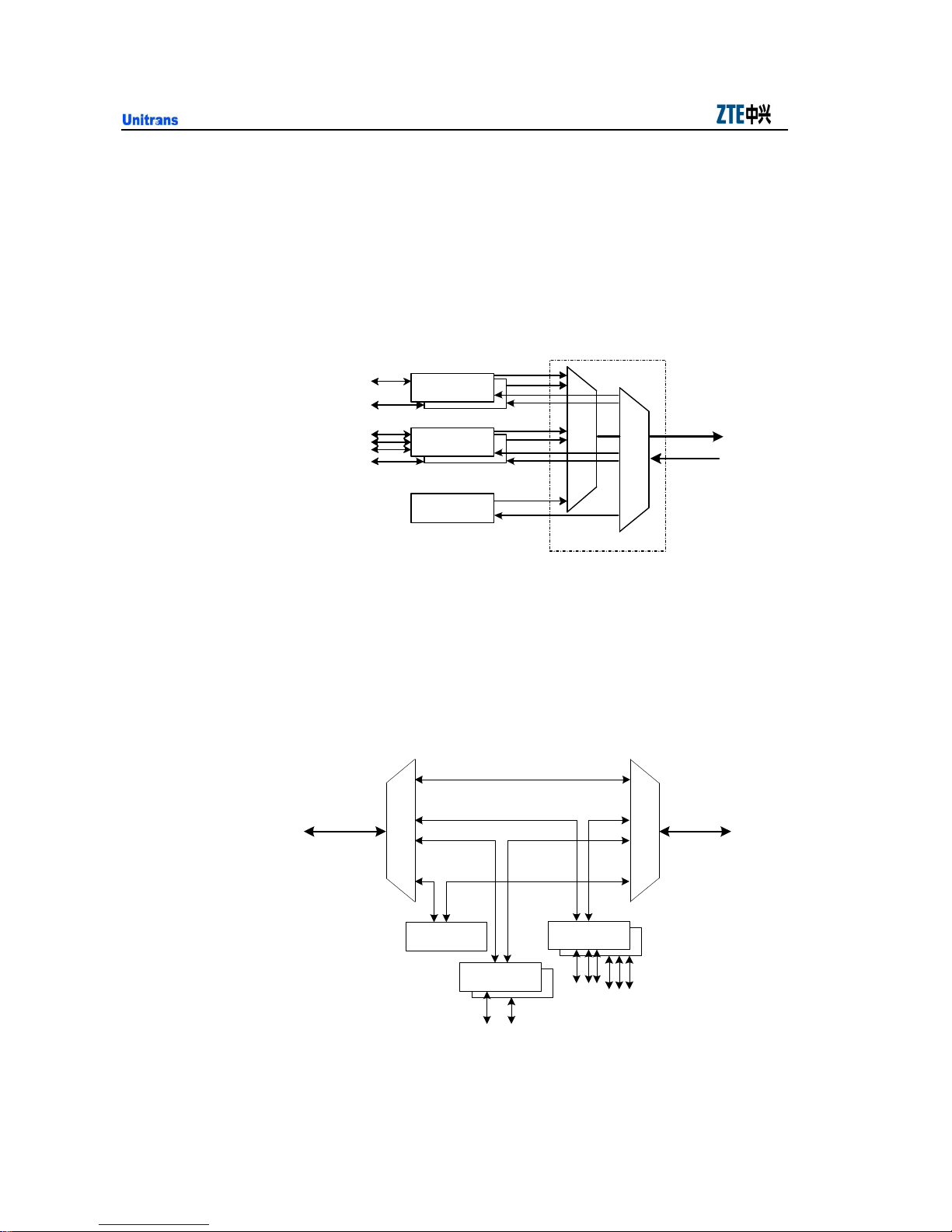
The ZXMP M600 can either be configured as OTM equipment or OADM equipment.
1. OTM
The OTM can add/drop all services and implement functions of a line terminal
node. When the ZXMP M600 is configured as OTM equipment, the relation
among the platforms is shown in Fig. 1.2-2.
Service signal
Service signal
Optical transfer
platform
Service
con vergence
pl atform
Monitor platform
Multiplexing
Demultiplexing
Multiplexing/
demultiplexing pl atform
Optical line
Fig. 1.2-2 Functional Structure of OTM Equipment
2. OADM
The OADM equipment can add/drop services with specified wavelengths and
directly connect other services. When the ZXMP M600 is configured as OADM
equipment, the relation among the platforms is shown in Fig. 1.2-3.
Multiplexing/ demultiplexing
platform
Optical line
(B side)
Optical line
(A side)
demultiplexing platform
Multiplexing/
Motor
platform
Crossover cable
Optical transfer
platform
Service signal
Service convergence
platform
Service signal
Fig. 1.2-3 Functional Structure of OADM Equipment
1-8
Page 25
Chapter 1 System Overview
1.2.2 Structure of Network Management Software System
The ZXMP M600 adopts Unitrans ZXONM E300 element management system
Unix/Windows (hereafter called ZXONM E300 for short) to implement software
management. The ZXONM E300 supports such functions as fault management,
performance management, security management, configuration management,
maintenance management and system management.
It consists of four layers, including an equipment layer, a Network Element (NE) layer,
NE management layer and subnet management layer and can provide Corba interface
to the network management layer.
Fig. 1.2-4 shows the structure of the ZXONM E300 system.
Network
management layer
Subnet
management layer
Network
element
management
layer
ECC
NE/Agent
ECC
Network
management layer
Equipment layer
MCU MCU
GUI(Cient)
F
Network element/ subnet
management system
Manager 1
Q
x
GNE/Agent
NE/Agent
……
ECC
NE/Agent
ECC
SS
GUI(Cient)
management system
LMT
f
NE/Agent
ECC
Network
management syst em
Corba
F
Subnet
Manager 3
F
F
Network element/ subnet
management system
Manager 2
Q
x
GNE/Agent
ECC
NE/Agent
NE/Agent
SS
M CU MCU MCUMCU
……
Network
management syst em
Corba
GUI(Cient)
……
ECC
ECC
NE/Agent GNE/Agent
F
Network element/ subnet
ECC
GUI(Cient)
FF
management system
Manager n
Q
x
S S
……
Fig. 1.2-4 Structure of the Network Management Software System
1-9
Page 26

ZXMP M600 (V1.0) Technical Manual
1. Layer description
1) Equipment layer (MCU)
The equipment layer supports the following functions:
Monitoring the alarm and performance of the boards
Receiving commands from the network management system
Controlling a board to implement specific operations.
2) NE layer, the Agent in the EMS
The NE layer supports the following functions:
Managing a single NE
Configuring the boards during the power-on and initialization of the NE
Monitoring the alarm and performance of the whole NE in the normal running
status
Receiving monitor commands from the NE management layer (Manager)
through the Gateway Network Element (GNE) and processing accordingly
3) NE management layer (Manager): to control and coordinate a series of NEs,
including the Manager, Graphical Interfaces (GUIs) and Local Maintenance
Terminal (LMT).
The NE management layer supports the following functions:
The core of the NE management layer is the Manager (or Server). It can manage
multiple subnets at the same time, control and coordinate NE devices.
The GUI provides graphical user interfaces to convert the users’ management
commands into the commands in the internal mode and send them to the
Manager.
The LMT controls the user authority and software function part to implement
the simple functions of both GUI and Manager. It provides simplified NE
management function for the deployment and maintenance of the local NE.
4) Subnet management layer: Its structure is similar to that of the NE management
layer. Through the EMS of the NE management layer, the commands for
configuring and maintaining the NEs can be implemented indirectly.
1-10
Page 27

Chapter 1 System Overview
The subnet management system sends the commands to the NE management
system, which then send them to the NE. After the commands are executed, the
NE sends responses to the subnet management system through the NE
management system. Besides, the NE management layer can provide Corba
interfaces to the network management layer.
2. Interface Description
1) QX interface:
In Fig. 1.2-4, it is the interface between the Agent and Manager, that is, the
interface between the NCP board and the computer where the Manager program
exists. It conforms to the TCP/IP protocol.
2) F interface:
In Fig. 1.2-4, it is the interface between the GUI and Manager, that is, the
interface between the GUI and the computer where the Manager program exists.
It conforms to the TCP/IP protocol.
3) f interface:
In Fig. 1.2-4, it is the interface between the Agent and LMT, that is, between the
NCP board and the maintenance terminal that is configured with the
corresponding network management software. The interface conforms to the
TCP/IP protocol.
4) S interface:
In Fig. 1.2-4, it is the interface between the Agent and the MCU, that is, the
communication interface between the NCP and other boards. The S interface
adopts HDLC-based point-to-point communication.
5) ECC interface
As shown in Fig. 1.2-4, it is the interface between two Agents, that is, the
communication interface between NEs. It adopts DCC to implement
communication and can support both user-defined communication protocol and
standard protocol. It implements the bridge function on the Agent.
For the detailed description of the network management software, please refer to
relevant network management manuals.
1-11
Page 28

ZXMP M600 (V1.0) Technical Manual
1.3 System Features
1. CWDM technique adopted to implement large-capacity transmission
Through an ordinary G.652 fiber, the ZXMP M600 equipment can provide 8+1
channels and the rate of each channel can reach 2.5Gbit/s. Here, “+1” indicates
the channel with a wavelength of 1310nm.
2. Open multi-service access mode
The ZXMP M600 equipment adopts an open design. It uses the optical/
electrical/ optical wavelength conversion technique to convert the accessed
optical signals into wavelength signals that conform to ITU-T Recommendation
G.694.2.
It can transparently transmit STM-N (N=1, 4, 16), POS, GbE, ATM optical
signals and can also directly access wavelength signals that conform to ITU-T
Recommendation G.694.2.
3. Service convergence capability
The ZXMP M600 can converge 4 channels of STM-1/STM-4 services to a
2.5Gbit/s channel.
4. Flexible filter design
the ZXMP M600 adopts a modular structure, supports flexible add/drop of
1~8+1 wavelengths and supports smooth upgrade.
5. Supporting multiple networking modes
The ZXMP M600 supports chain, ring and tangent networks
6. Providing multiple power access modes
The ZXMP M600 equipment can access -48V DC, +24V DC or -60V DC power
supplies.
Each subrack can adopt two power boards to implement 1+1 power hot backup
to guarantee the reliable power supply of the system.
7. Supporting the mixed plugging and hot plugging/unplugging of the boards
In the corresponding CWU and SMU shelves of the ZXMP M600 equipment, all
boards except the power board and the NCP board can be plugged in a mixed
1-12
Page 29

Chapter 1 System Overview
way and can be plugged/unplugged in a hot way. This makes the configuration
flexible and the maintenance convenient.
8. Providing a powerful and unique EMS
The ZXONM E300 network management system adopted by the ZXMP M600
provides friendly and convenient user interfaces and supports the management
of the NE layer, NE management layer and network management layer. It can
implement such functions as fault management, performance management,
security management, configuration management, maintenance management and
system management. Besides, it shows the following features:
1) Adopting object-oriented technique during the design and development and
implementing 3-layered C/S structure where the interface, service and data
layers are separated one another. Thus, the system features perfect expandability
and adaptability.
2) Adopting the standard L2 Ethernet switching technique, which greatly facilitates
the construction of complicated networks
3) Implementing real-time synchronization and automatic changeover between the
data of active/standby nodes, thus greatly improving the reliability and
availability of the EMS
4) Implementing online upgrade of the foreground and background NM software as
well as the embedded software of the boards without interrupting the service
5) Managing the CWDM, DWDM and SDH equipment in a unified way.
1-13
Page 30

ZXMP M600 (V1.0) Technical Manual
1.4 Applicable Standards/Recommendations
The design of the ZXMP M600 system conforms to the following recommendations
and standards:
ITU-T G.652-2003-3 Characteristics of a single-mode optical fibre cable
ITU-T G.653-2003-12 Characteristics of a dispersion-shifted single-mode optical
fibre cable
ITU-T G.655-2003-3 Characterizations of a non-zero dispersion single-mode
optical fibre cable
ITU-T G.694.2-2003-12 Spectral grids for WDM applications: CWDM wavelength
grid
ITU-T G.695-2004-2 Optical interfaces for Coarse Wavelength Division
Multiplexing applications
ITU-T G .703-2001-11 Physical/electrical characteristics of hierarchical digital
interfaces
ITU-T G.783-2000-10 Characteristics of synchronous digital hierarchy (SDH)
equipment functional blocks
ITU-T G.798-2002-06 Characteristics of optical transport network equipment
functional blocks
ITU-TG.825-2002-06 The control of jitter and wander within digital networks which
are based on the synchronous digital hierarchy (SDH)
ITU-T G.959.1 Optical transport network physical layer interfaces
ITU-T G.871 Framework for optical transport network recommendations
ITU-T G.872 Architecture of optical transport networks
ITU-T G.873 Optical Transport Networks Requirements
ITU-T G.874 Management Aspects of Optical Transport Network Element
ITU-T G.875 Optical Transport Network Management Information Model for The
Network Element View
1-14
Page 31

Chapter 1 System Overview
ITU-T .957-1999-6 Optical interfaces for equipment and systems relating to the
synchronous digital hierarchy
ESCON phy layer OS390/LIBRARY
IEC 60825-1-2000 Safety of Laser Product
ISO/IEC-9314-3 Information processing systems-Fibre distributed Data Interface
(FDDI)-Part 3: physical Layer Medium Dependent (PMD)
Bellcore GR253-1999 Synchronous Optical Network (SONET) Transport Systems:
Common Generic Criteria
1-15
Page 32

Page 33

2 Technical Indices
This chapter introduces the technical indices of the ZXMP M600, including the
structure indices, power indices and board performance indices.
2.1 System Indices
8+1 wavelength system compliance to S-C8L1-1D2/3/5 application code of G.695
4+1 wavelength system can upgrade to 8+1 system
20Gb/s Maximum capacity (8x2.5G)
OTM and OADM nodes support P2P and ring topology
18dB link budget for 8+1 system w/o reg
20dB link budget for 4+1 system w/o reg
Fiber type G.652, G.653, G.655
Wavelengths is compliance to G.694.2
2-1
Page 34

ZXMP M600 (V1.0) Technical Manual
2.2 Structure Indices
The outline dimensions and weight indices of the component parts of the ZXMP M600
are shown in Table 2.2-1.
Table 2.2-1 Outline Dimensions and Weight Indices of the ZXMP M600 Component Parts
Component Parts Outline Dimensions Weight (kg)
ZXMP M600 CWU shelf 43.6mm (H) ×441mm (W) ×241mm (D)
ZXMP M600 SMU shelf 43.6mm (H) ×441mm (W) ×241mm (D)
Fan Box 41.2mm (H) × 30.6mm (W) × 222mm (D) ——
-48V DC Power Board (PCWAS)
+24V DC Power Board (PCWBS)
-60V DC Power Board (PCWCS)
Sub-Rate Multiplexing (SRM42)
Gigabit Ethernet Multplexing Unit
(GEM2)
Net Control Processor (NCP)
Optical Transponder Unit (OTU)
Optical Dmux/Mux Unit (OMD)
Optical Add/Drop Unit (OAD)
20.4mm (H) ×110.6mm (W) ×210mm (D) ——
41.2mm (H) ×325.5mm (W) ×210mm (D) ——
20.4mm (H) ×162.6mm (W) ×210mm (D) ——
3 (empty)
7 (in full configuration)
3 (empty)
7 (in full configuration)
Note:
1. When ZXMP M600 is to be installed in a cabinet, mounting lugs should be installed on both sides of the shelf to fix the shelf to the cabinet. The
sizes of the shelf with mounting lugs are 43.6mm (H) ×482.6mm (W) ×241mm (D).
2. The “H” and “W” in the outline dimensions of the boards indicate the size of the board panel, while “D” indicates a dimension of the PCB board.
3. For the detailed description of the component parts, please see Unitrans ZXMP M600 (V1.0) Metro CWDM Equipment Hardware Manual
2-2
Page 35

Chapter 2 Technical Indices
2.3 Power Indices
2.3.1 Voltage Requirements
The ZXMP M600 supports DC power supplies. Compliance to ETSI EN 300 132-2
V2.1.2 (2003-09)
1. DC power
Rated input voltage: -48V
Fluctuation allowance: -57V~-40V
Rated input voltage: +24V
Fluctuation allowance: +20V~+30V
Rated input voltage: -60V
Fluctuation allowance: -75V~-45V
2.3.2 Power Consumption Requirements
The power consumption indices of ZXMP M600 boards are shown in Table 2.3-1.
Table 2.3-1 Power Consumption Indices of the ZXMP M600 Boards/Units
Board/ Unit Name Abbreviation Power Consumption (W)
Net Control Processor NCP 6.0
Power Board PCWCS/PCWAS 5.0
Optical Transponder Unit OTU 8.0
Optical Dmux/Mux Unit OMD 1.0
Optical Add/Drop Unit OAD 1.0
Sub-Rate Multiplexing SRM42 22.0
Gigabit Ethernet Multiplexing GEM2 20.0
CWDM Unit CWU 35.0 (in full configuration)
Subrate Multiplexer Unit SMU 32.0 (in full configuration)
Note: The full configuration of CWU indicates 3×OTU+1×OMD+2×PCW, while that of SMU is 1×SRM42+2×PCW.
The power consumption indices in the above table are values under normal temperature.
In practice, a certain power redundancy should be provided to ensure the reliable
2-3
Page 36

ZXMP M600 (V1.0) Technical Manual
operation of the equipment. Therefore, the practical power consumption should be
1.5~1.8 times of that under normal temperature.
2.4 Environment Requirements
2.4.1 Grounding Requirements
1. Equipment internal grounding requirements
1) The board should be in reliable contact with the shell of the equipment through
the captive screw on the panel.
2) The protection ground should be isolated from the power ground.
3) If the ZXMP M600 equipment is placed in a cabinet, the mounting lugs of the
shelf should be reliably connected to the cabinet. Besides, to be grounded, the
shelf should be connected with the grounding copper bar of the equipment room
through the cabinet grounding point. If the equipment is installed on a desktop,
it should be grounded through the connection between the wiring terminal of the
shelf and the grounding copper bar of the equipment room.
2. Grounding requirements of DC power
1) The Protection Ground (PGND) should be grounded through the shelf shell.
2) The work ground (-48V GND, +24V GND or -60V GND) should be isolated
from the protection ground.
3) If independent grounding is adopted in the equipment room, the grounding
resistance of the working ground should be 4Ω and that of the protection ground
should also be 4Ω.
4) If joint grounding is adopted in the equipment room, then the grounding
resistance should be 1Ω.
2.4.2 Temperature and Humidity Requirements
The requirements of ZXMP M600 equipment for environment temperature and relative
humidity are shown in Table 2.4-1.
2-4
Page 37

Chapter 2 Technical Indices
Item Requirements
Environment temperature 0°C~+45°C
Transportation and storage temperature -20°C~ +60°C
Relative humidity 10%~90% (35°C)
2.4.3 Cleanness Requirements
The cleanness requirements involve dust and corrosive gas in the air. The equipment
should work in an equipment room that meets the following cleanness requirements:
1. There should be no explosive, conductive, magnetic-conductive or corrosive
dust in the transmission equipment room.
2. The density of the dusts with a diameter greater than 5µm should be less or
equal to 3×10⁴ particle/m3.
3. There should be no such gas as SO2 or NH3 that will corrode metal or damage
the insulator.
Table 2.4-1 Temperature and Humidity Requirements
4. The equipment should be kept clean. Besides, the door and the windows should
be sealed.
2.4.4 Dustproof and Anti-corrosion Requirements
According to the application range of GB4798 and the ZXMP M600, the dustproof and
anti-corrosion requirements are as follows:
1. Storage environment: 1K5/1Z1/1B2/1C2/1S3/1M3; with the continuous storage
time being 180 days
2. Transportation environment: 2K4P/2B2/2C2/2S3/2M3; the continuous
transportation time being 30 days
3. Operation environment: 3K5/3Z2/3Z7/3B2/3C2/3S2/3M3; the continuous
operation time being 20 years.
2.5 Working Wavelengths
The working wavelengths of the ZXMP M600 equipment are in strict compliance with
ITU-T Recommendation G.694.2. Specific central wavelengths and central frequencies
used in a multi-channel system are adopted.
2-5
Page 38

ZXMP M600 (V1.0) Technical Manual
1. When ordinary fibers are adopted, the common working wavelengths of the
ZXMP M600 are 8+1 wavelengths, and the wavelength interval is 20nm. “+1”
indicates to add a channel for the 1310nm window. The distribution of the
wavelengths is shown in Table 2.5-1.
Table 2.5-1 Wavelength Distribution of the ZXMP M600 Equipment (with ordinary fibers adopted)
Wavelength No. Central Wavelength/Frequency (nm)
0 1260nm~1360nm O-Band
1 1471
2 1491
3 1511
4 1531
5 1551
6 1571
7 1591
8 1611
Note: 0 standards for the 1310nm wavelength.
2.6 Reliability
MTBF/ch ≥ 50000 hours (The Mean Time Between Failures of a single channel of
equipment at each node will be about 6 years.)
2.7 Optical safety and electrical safety
1. When installing and making input and output connections for the equipment,
the relevant safety standards e.g.IEC60950/VDE0805/EN60950/UL60950 must
be compiled.
2. The equipment is intended to be installed by SERVICE PERSONNEL and has
been provided with protective earthing connection.
3. For short circuit and overcurrent protection, the equipment is protected by DC
supply.
4. Maximum ambient temperature around the equipment should not exceed 55°C.
5. The operating wavelength of the system is 1260nm to 1620nm.
2-6
Page 39
Chapter 2 Technical Indices
6. All the laser modules in the equipment comply with the requirements of IEC
60825-1:1994+A2:2001 and IEC 60825-2:2000.
7. Reproduction of all warning labels.
2.8 Indices of System Component Parts
2.8.1 Performance Indices of OMD
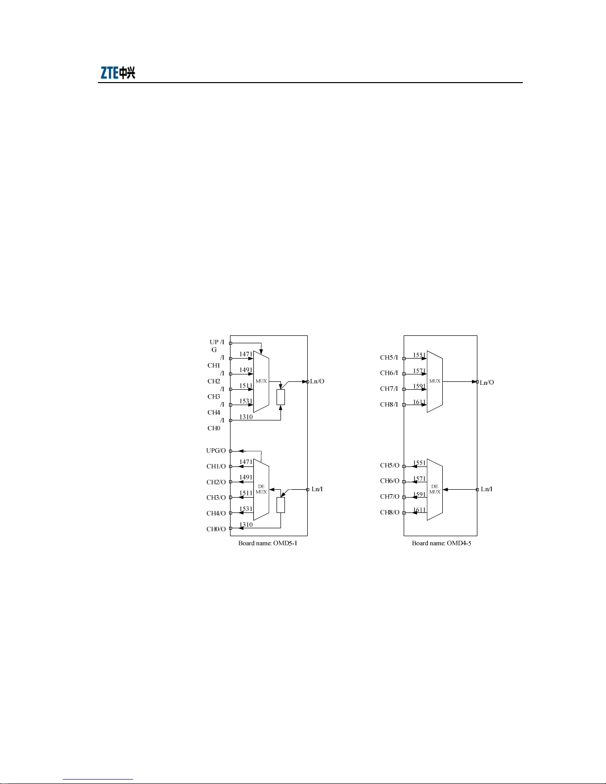
OMDs used in the ZXMP M600 equipments include OMD5-1, OMD4-1 and OMD4-5.
The figures before “-” respectively indicate the number of the channels on the board,
while the figures after “-” respectively indicate the serial number of the starting
wavelength.
The optical interfaces of each board are shown in Fig. 2.8-1.
UPG: Upgrade interface; Ln: line interface; CH0: 1310 window; /I: input; /O: output
Different OMD units can be combined to implement the multiplexing/demultiplexing
of different wavelengths.
1. OMD5-1: multiplexing/ demultiplexing 4+1 wavelengths. “+1” indicates the
Fig. 2.8-1 Optical Interfaces of OMD Units
1310 channel.
2-7
Page 40
ZXMP M600 (V1.0) Technical Manual
2. OMD5-1+OMD4-5: multiplexing/ demultiplexing 8+1 wavelengths. “+1”
indicates the 1310 channel.
Take common 4+1 and 8+1 wavelengths for example. The major performance indices
of the ZXMP M600 OMD units are as shown in Table 2.8-1.
Table 2.8-1 Performance Indices of OMD
Parameter Unit 4+1 Wavelengths 8+1 Wavelengths
Bandwidth of CWDM channel @ 0.5dB nm λC ±6.5 λC ±6.5
Insertion loss
(including the
connector)
Isolation
Return loss dB ≥40 ≥40
Line- CWDM dB ≤2.3 (note 1) ≤3.5(note 1)
Line -UPG dB ≤2.3 ——
Line - 1310nm dB ≤1.2 ≤1.2
Wavelengths adjacent to the 8
wavelengths of the CWDM
channel
dB
DEMUX: ≥30
MUX: NA
DEMUX: ≥30
MUX: NA
Note 1: Please note that 2.3dB loss is intended for system requirement. The actual product performance is much better
than the requirement, up to 0.5dB can be reduced in OMD loss when calculating budget. Configuration can use typical
value of 2.0dB (4+1 Wavelengths) and 3.0dB (8+1 Wavelengths).
2.8.2 Performance Indices of OAD Units
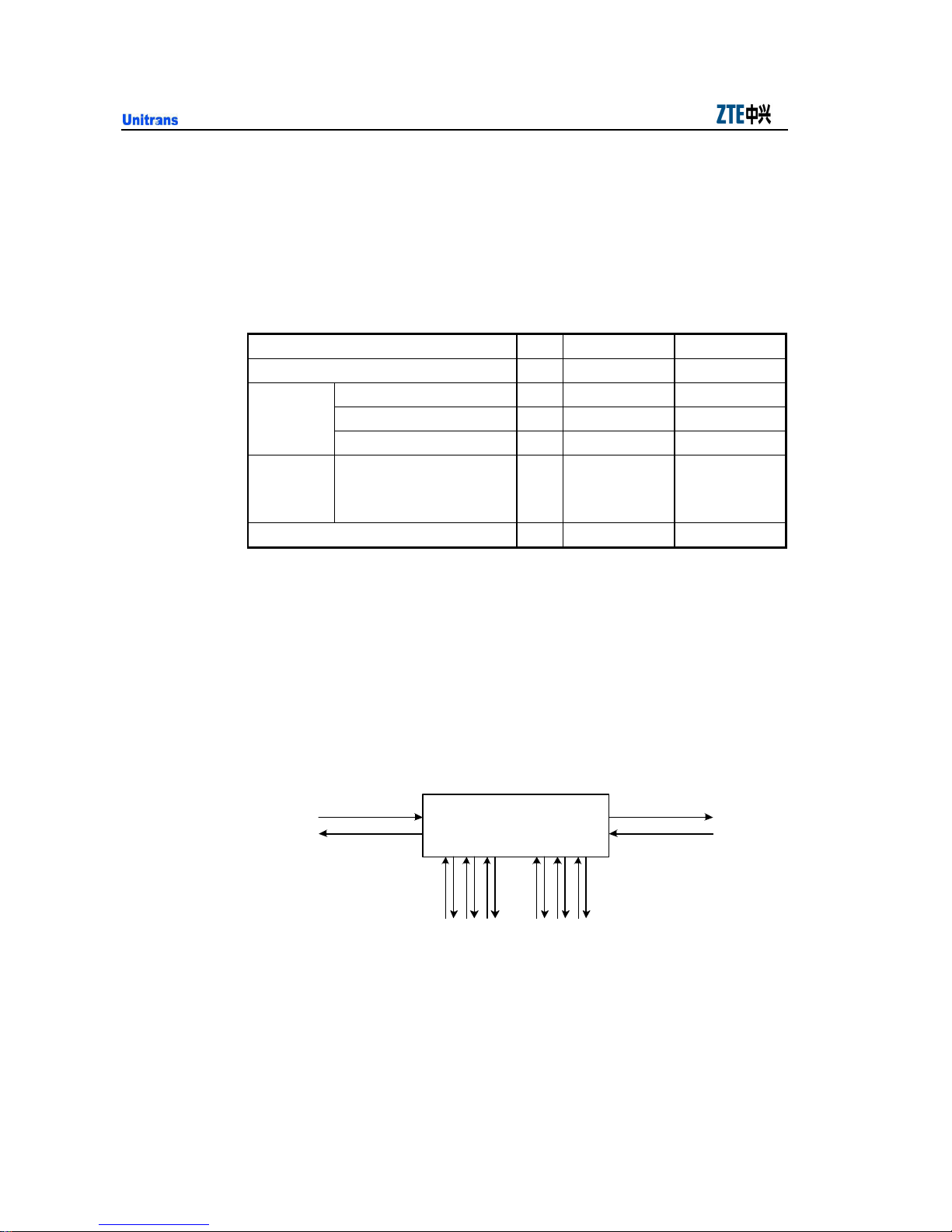
The OAD units used in the ZXMP M600 system include OAD1, OAD2 and OAD3.
The figure in each unit indicates the number of add/drop channels.
The optical interfaces of the OAD units are shown in Fig. 2.8-2.
ABLine/I
ABLine/O
Fig. 2.8-2 Optical Interfaces of OAD Units
Add/drop multiplexer
ABChi
i=1, 2, 3
BALine/O
BALine/I
BAChi
Here, A Line and A_ADi interfaces indicate the line optical interface and channel
optical interface at the A side respectively; B Line and B_ADi respectively indicate the
2-8
Page 41

Chapter 2 Technical Indices
1 (Downlink and uplink channels of 1310
1 (Downlink and uplink channels of 1310
line optical interface and the channel optical interface at the B side; /I indicates input
while /O indicates output. For example, “A Line/O” indicates the output line optical
interface at the A side.
The major performance indices of the OAD units are shown in Table 2.8-2.
Table 2.8-2 Performance Indices of OAD Units
Parameter Unit CWDM Channel 1310nm Window
Bandwidth of CWDM channel
@ 0.5dB
1310/1550 window range nm ——
In-Out dB ≤1 (OAD1), ≤2 (OAD2), ≤3 (OAD3)
In-Drop dB
Insertion loss
(including the
connector)
Add-Out dB
CWDM Isolation dB
Return loss dB ≥45
nm λC±6.5 ——
1260 ~ 1360 (transmission port)
1461 ~ 1621 (reflection port)
≤
wavelength in OAD1, OAD2, OAD3)
≤1 (one of the 8 CWDM wavelengths of OAD1)
≤2 (one of the 8 CWDM wavelengths of OAD2)
≤3 (one of the 8 CWDM wavelengths of OAD3)
≤
wavelength in OAD1, OAD2, OAD3)
≤1 (one of the 8 CWDM wavelengths of OAD1)
≤2 (one of the 8 CWDM wavelengths of OAD2)
≤3 (one of the 8 CWDM wavelengths of OAD3)
DEMUX: ≥30
MUX: NA
——
2-9
Page 42

ZXMP M600 (V1.0) Technical Manual
T
2.8.3 OTU Interface Indices
The OTU module used in the ZXMP M600 includes a line optical transmitting module,
line end optical receiving module and client optical transceiving module.
1. Indices of the line end optical transmitting port
The Indices of the line end optical transmitting port are shown in Table 2.8-3.
S point Parameters at the Optical Output End Unit Indices
Optical source type SLM
Optical signal rate (multiple rates) bit/s
Maximum -20dB bandwidth nm 1
Minimum side mode suppression ratio dB 30
Average transmitting optical power (with the
shell temperature between 0°C~70°C)
Minimum extinction ratio dB 8.2
Eye pattern diagram
Wavelength precision (the shell temperature
being 0°C~70°C)
Dispersion tolerance ps/nm 1600
Table 2.8-3 Indices of the Line End Optical Transmitting Port
155M/622M/2.5G
1.25G (GE signals)
dBm 0~5 (note 1)
STM-N signals conform to ITU-
Recommendation G.957
That of the GE signals conforms to
IEEE802.3z.
1471/1491/1511/1531/1551/1571/1591/161
nm
1±6.5
Or 1260~1360 (to 1310nm wavelength)
Note: actually output power is 0~1dBm.
2-10
Page 43

Chapter 2 Technical Indices
When the SDH signals are being received,
the jitter performance conforms to the
T
2. Indices of the line end optical receiving port
The Indices of the line end optical receiving port are shown in Table 2.8-4.
Table 2.8-4 Indices of the Line End Optical Receiving Port
R Point Parameters at the Optical Input End Unit Indices
Optical signal rate (multiple rates) bit/s 155M/622M/2.5G/1.25G (GE signals)
Optical signal rate (continuous rate) bit/s 10M~2.5G
Receiving sensitivity: 2.5Gbit/s) dBm <-28 (APD)
Receiver reflection dB >27
Overload receiving power dBm >-9 (APD)
Wavelength range of input signals nm 1460~1620
Jitter performance
requirements for regenerator in ITU-
Recommendation G.958.
Note:
1. For receiving sensitivity at 1E-15, use 2 dB as the penalty.
2. If Receiving Power is greater than -9dBm, external attenuator is required to reduce the receiving power to below
-9dBm.
2-11
Page 44

ZXMP M600 (V1.0) Technical Manual
3. Indices of client optical transceiving module
When STM-1/4/16 signals are transceived at the client, the optical indices
conform to ITU-T Recommendation G.957; when GE signals are transceived,
the optical indices conform to IEEE802.3, as shown in Table 2.8-5.
Table 2.8-5 Indices of Client Optical Transceiving Module
Unit STM-16I-16.1 1000BASE-LX 1000BASE-SX (50µm)
Optical source type MLM SLM MLM
Optical signal rate Mbit/s 2488.32 1250 1250
Maximum bandwidth (RMS) nm 4 4 0.85
Maximum -20dB bandwidth nm —— —— ——
Average transmitting power dB -10~-3 -11.5~-3 -9.5~-4
Minimum extinction ratio 8.2 9 9
Eye pattern diagram G0.957 IEEE802.3z IEEE802.3z
Wavelength range nm 1260~1360 1270~1355 770~860
Receiver type PIN PIN PIN
Minimum sensitivity dBm -18 -19 -17
Minimum overload dBm -3 -3 0
Maximum optical reflection dB -27 —— ——
Minimum optical return loss dB 24 12 12
Line attenuation range dB 0~7 8 7.5
Max transmission distance m 2000 5000 500
Optical Fiber type SMF SMF MMF
2-12
Page 45

Chapter 2 Technical Indices
2.8.4 Performance Indices of Optical Supervisor Channel
The optical monitoring channel of the ZXMP M600 is implemented on the NCP board.
Its major performance indices are shown in Table 2.8-6.
Table 2.8-6 Major Performance Indices of Optical Monitoring Channel
Central Wavelength (nm) 1310±50 1511±6.5
Signal code pattern 4B5B 4B5B
Monitoring rate 100Mbit/s 100Mbit/s
Optical source type SLM LD SLM LD
Signal transmitting rate (dBm) -5~0 -5~0
Minimum receiving sensitivity (dBm) -34 -34
Minimum overload power (dBm) -10 -10
2.8.5 SRM42 Interface Indices
The OTU module used in the ZXMP M600 includes a line optical transmitting module,
line end optical receiving module and client optical transceiving module.
1. Indices of the line end optical transmitting port
The Indices of the line end optical transmitting port are the same as OTU shown
in Table 2.8-3.
2. Indices of the line end optical receiving port
The Indices of the line end optical receiving port are the same as OTU shown in
Table 2.8-4.
2-13
Page 46

ZXMP M600 (V1.0) Technical Manual
3. Indices of client optical transceiving module
When STM-1/4 signals are transceived at the client, the optical indices conform
to ITU-T Recommendation G.957; as shown in Table 2.8-7
Table 2.8-7 Indices of Client Optical Transceiving Module
Unit STM-1 S-1.1 STM-4 S-4.1
Optical source type MLM MLM
Optical signal rate Mbit/s 155.520 622.080
Maximum bandwidth (RMS) nm 7.7 4
Maximum -20dB bandwidth nm —— ——
Average transmitting power dB -15~-8 -15~-8
Minimum extinction ratio 8.2 8.2
Eye pattern diagram G.957 G.957
Wavelength range nm 1261-1360
Receiver type PIN PIN
Minimum sensitivity dBm -28 -28
Minimum overload dBm -8 -8
Line attenuation range dB 0-12 0-12
Max transmission distance m 15000 15000
Optical Fiber type SMF SMF
1293-1334/
1274-1356
2-14
Page 47

3 System Function
This chapter deals with the functions of the ZXMP M600 equipment, including the
transmission function, service access capability, communication monitoring function,
power input/output function, grounding function and protection function.
3.1 Line Transmission Function
1. The ZXMP M600 is suitable for large-capacity optical transmission.
When ordinary fibers are used, the maximum number of working wavelengths
of the system reaches 8+1 (“+1” indicates to add a 1310 channel);
The maximum transmission rate is 2.5Gbit/s. The wavelength selection and
wavelength interval are in strict compliance with ITU-T Recommendation
G.694.2.
3-1
Besides, the system supports multiple networking modes such as chain network,
ring network and tangent ring network.
2. As the node span of a MAN is flexible, the system supports various node spans.
Page 48

ZXMP M600 (V1.0) Technical Manual
3.2 Service Functions
3.2.1 Service Access Function
The ZXMP M600 can access the following services:
SDH service, including STM-1/4/16 service
SONET service, including OC-3/12/48 service
ATM service or POS service; the latter including VC4, VC4-4c and VC4-16c
Ethernet service, including GbE
3.2.2 Service Convergence Function
The ZXMP M600 can multiplex (converge) and demultiplex low rate signals.
Each SRM42 board can multiplex 4 channels of 155Mbit/s and 622Mbit/s SDH
signals or ATM signals.
Each GEM2 board can multiplex channels of GbE signals.
3-2
Page 49
Chapter 3 System Function
3.3 Communication and Monitoring Functions
3.3.1 Communication between EMS and Access Point
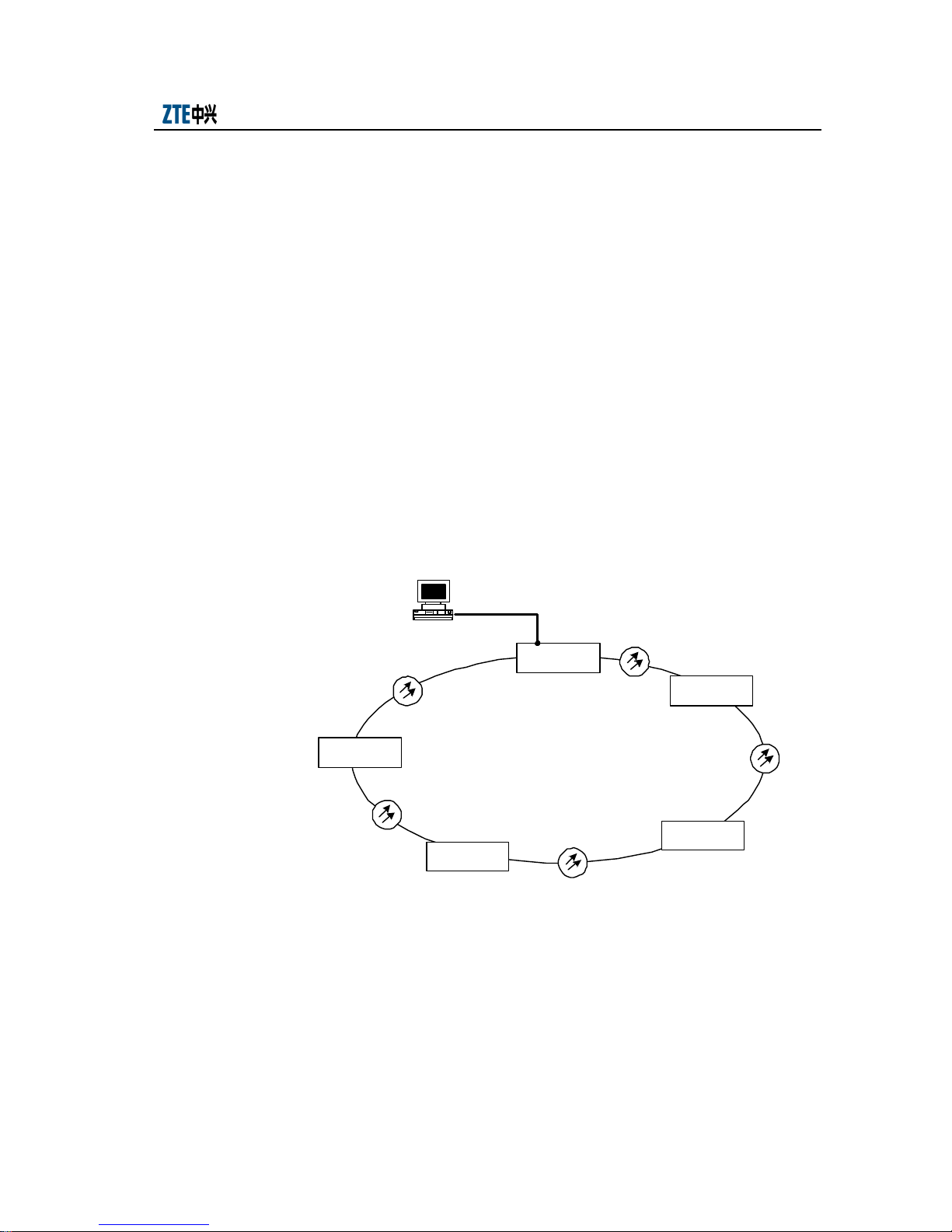
The communication between an access point and the EMS can be implemented either
through an Ethernet electrical interface or a DB9 socket.
Both interfaces are on the NCP board. The former is marked as ETH1 or ETH2, while
the latter marked as RS232.
1. Direct connection with the EMS through an Ethernet electrical interface
The electrical interface on the NCP board of the ZXMP M600 equipment can
implement the automatic cross-connection function supported by interface
cables. Thus, either cross-connect or straight-through network cable can be
connected to the EMS to implement the communication between the EMS and
the accessed network element.
Network
management system
CWDM n ode 2
CWDM n ode 3
Fig. 3.3-1 Connection between the Access Point and the EMS (through an Ethernet interface)
ET H1 or ET H2 interface
CWDM n ode 1
CWDM n ode 5
CWDM n ode 4
2. Connection with the EMS through bound SDH equipment of ZTE
An optical channel consists of CWDM nodes. Though the CWDM nodes, logic
connection is set up between the SDH nodes. If the CWDM equipment has not
adopted 1310 or 1510 wavelength to transmit the monitoring information, then
the DCC channel of the ZTE SDH equipment can be used for monitoring.
3-3
Page 50
ZXMP M600 (V1.0) Technical Manual
The connection between the CWDM/ SDH nodes and the EMS is described
below:
1) For the CWDM equipment that does not serve as an element management access
node, its ETH1 or ETH2 interface on the NCP board of can be connected with
the Ethernet interface of the SDH equipment.
2) The Ethernet interface on the NCP board of the CWDM equipment that serves
as an access node for the EMS can be connected to the HUB.
3) The Ethernet interface of the SDH equipment that serves as an access node for
the EMS can be connected with the HUB.
4) The HUB is connected to the EMS.
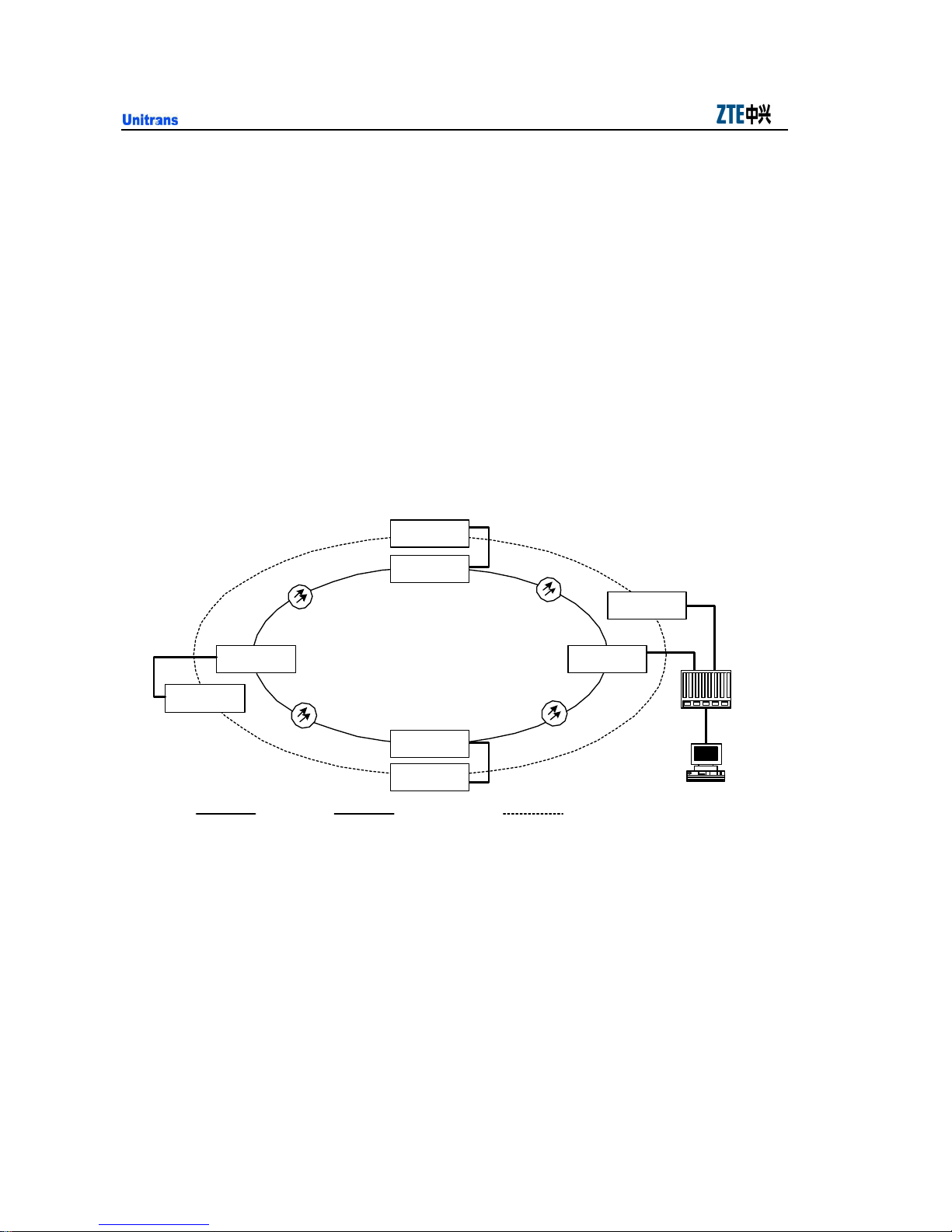
Take a ring network as an example. The connection is shown in Fig. 3.3-2.
SDH no de 1
CWDM n ode 1
SDH no de 2
CWDM node 2
CWDM n ode 3
SDH no de 3
Network cable Physical optical line
Fig. 3.3-2 Connection with the EMS Through SDH Equipment
The SDH nodes and CWDM nodes share the same EMS, ECC route and DCC
route.
Each SDH node is equivalent to a router that adopts the OSPF protocol while
each CWDM node is equivalent to a L2 switch. The SDH and CWDM nodes
form a local Ethernet at last. The network management information between the
EMS and CWDM node is transmitted through the DCC and ECC channels of
the SDH equipment.
SDH no de 4
CWDM node 4
Logic optical line
Hub
Network
management syst em
3-4
Page 51
Chapter 3 System Function
In Fig. 3.3-2, the data between CWDM node 3 that serves as a non-access node
and the EMS is taken as an example to describe the data report flow. Here, the
report from CWDM node 3 is transferred to the aggregate overhead of the SDH
equipment through the Ethernet interface of SDH node 3. It is then sent to the
access node SDH node 4 and further to the EMS server through the HUB.
Tips
This access mode requires the SDH equipment to support and run the OSPF protocol.
3. Communication with the EMS through RS232
The RS232 interface on the NCP board can either serve as an f interface or drive
the Modem.
1) When serving as an f interface, RS232 is used to connect the LMT. The
networking mode is shown in Fig. 1.2-4.
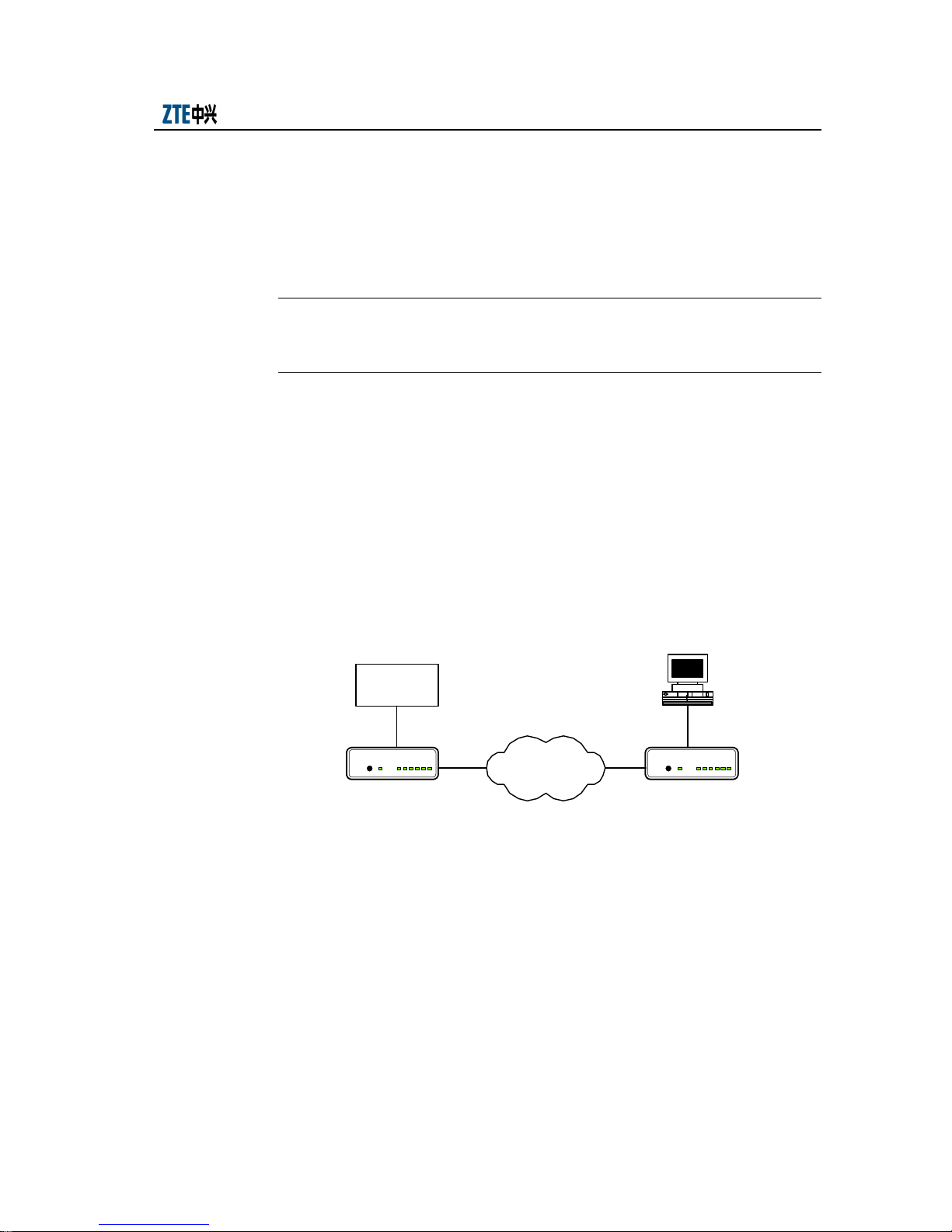
2) When used to drive the Modem, RS232 can be used to manage the equipment
through dialing up, as shown in Fig. 3.3-3.
CWDM
equipment
RS232
TALK / DATA
RS CS TR R D TD CD
TALK
Modem
Fig. 3.3-3 Connection with the EMS through RS232
3.3.2 Communication between Nodes
WDM equipment has no channel for transmitting network management information. It
must access the NM information to the transmitted user subscriber signals through a
specified interface to implement transparent transmission of the information.
On the other hand, the NM information of the ZXMP M600 is transmitted to the
subscriber signals through AOSC and BOSC interfaces on the NCP board. The
Telephone
switching network
Network
management system
TALK / DATA
RS CS TR RDTD CD
TALK
M odem
3-5
Page 52
ZXMP M600 (V1.0) Technical Manual
monitoring channel is of the 100BASE-FX type and the wavelength can be either
1310nm or 1510nm.
3.3.3 Intra-node Communication and Monitoring
The ZXMP M600 equipment can add/drop and multiplex multiple wavelengths through
the combination of master CWU+ slave CWU or master CWU+slave CWU+ SMU.
In this case, the inter-node communication and monitoring information is implemented
through the NCP board on the master CWU shelf, while the communication and
monitoring information between different shelves in the same node is implemented
through the S interface on the power board of each shelf.
S interface is a 15-pin socket. Each PCW board provides one S interface and each shelf
can be configured with 2 PCWAS boards.
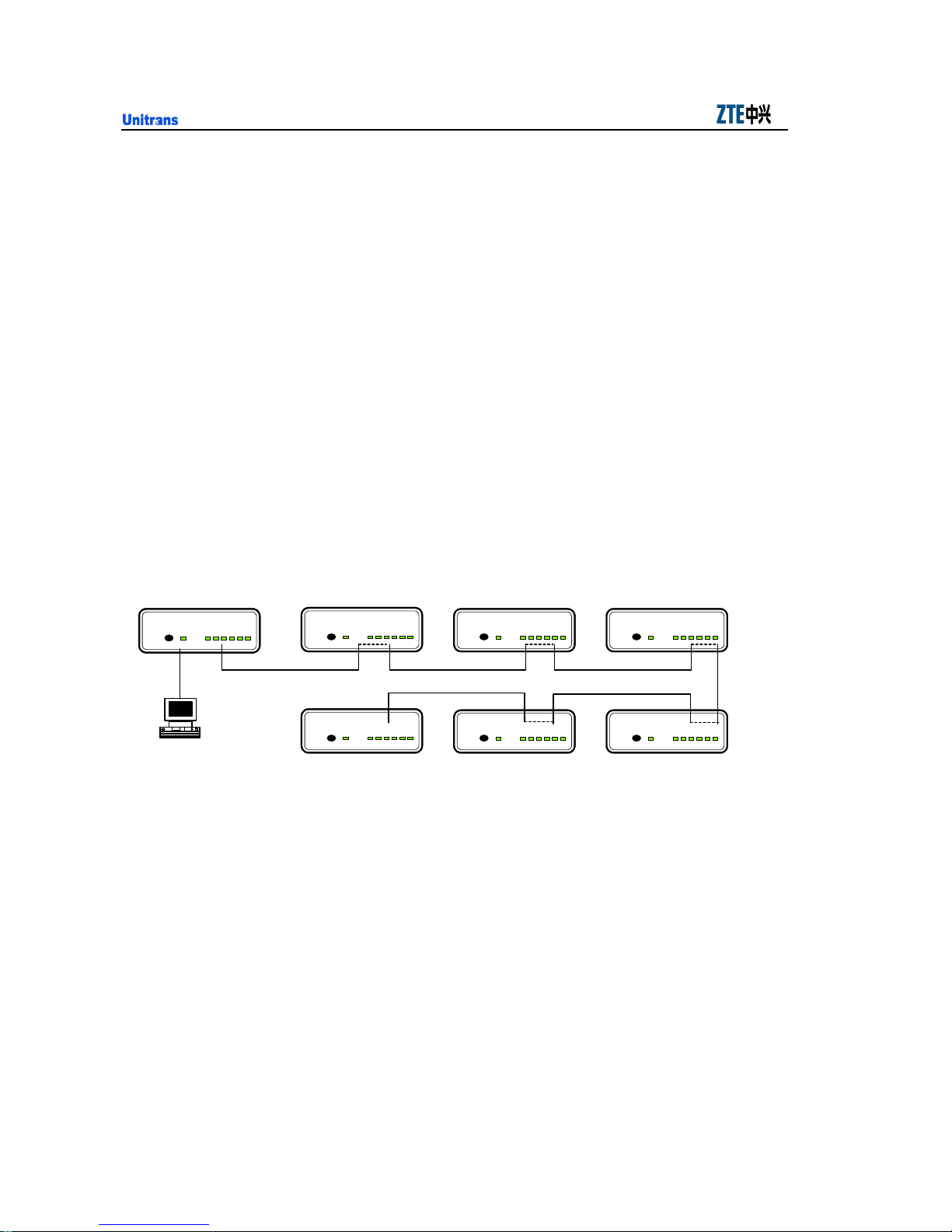
Take the EMS access point in full configuration for example. The connection of the
interfaces between the shelves is as shown in Fig. 3.3-4.
Master CWU
TALK / DATA
RS CS TR RD TD CD
TALK
Qx
Network
management system
CWU
TALK / DATA
RS CS TR RD TD CD
TALK
S int erf ace S interface S int erface
S int erface
TALK / DATA
RS CS TR RD TD CD
TALK
SMU SMU SMU
Fig. 3.3-4 Intra-node Communication and Monitoring Channel
CWU
TALK / DATA
RS CS TR RD TD CD
TALK
S int erf ace S interface
S int erf ace
TALK / DATA
TALK RS CS TR RD TD CD
S int erf ace
RS CS TR RD TD CD
CWU
TALK / DATA
TALK
S int erface
S int erf ace
TALK / DATA
TALK
RS CS TR RD TD CD
S int erface
S int erface
3-6
Page 53

Chapter 3 System Function
3.4 Power Input and Output Functions
1. Power Input
The ZXMP M600 supports DC input. The voltage of DC power is –48V, +24V
or –60V.
Two DC power boards can be configured to implement 1+1 hot backup.
In addition, the ZXMP M600 supports input over-voltage and over-current
protection as well as the reverse connection protection of DC input.
2. Power output
The ZXMP M600 equipment outputs +5V/-48V DC with a power of 50W
through power board. Here, +5V is power voltage for the CWU board while
-48V is for the SMU board.
The transformed power is transmitted to the boards through power sockets on
the backplane. Power supplies of the boards are independent from one another.
3.5 Grounding Function
1. In the equipment, the DC work ground should be isolated from the protection
ground.
2. The protection ground of the power input should be connected to the shell of the
shelf.
3. The shielding ground of the board should be connected to the shell of the shelf
through the board panel.
4. A grounding hole is set at the back of the shelf. It is marked as and is
connected to the grounding copper bar of the equipment room through wiring
terminals.
3.6 Alarm Output Function
The ZXMP M600 supports alarm output function. It can output critical alarm, major
alarm and ring trip signals to the row-first cabinet in the equipment room.
The alarm output interface of the ZXMP M600 is situated on the NCP board of the
CWU shelf. It is a RJ11 socket and is marked as ALM.
3-7
Page 54
ZXMP M600 (V1.0) Technical Manual
3.7 Protection Function
The protection function of the ZXMP M600 supports 1+1 channel protection based on
the ring network.
3.7.1 Ring Network Protection
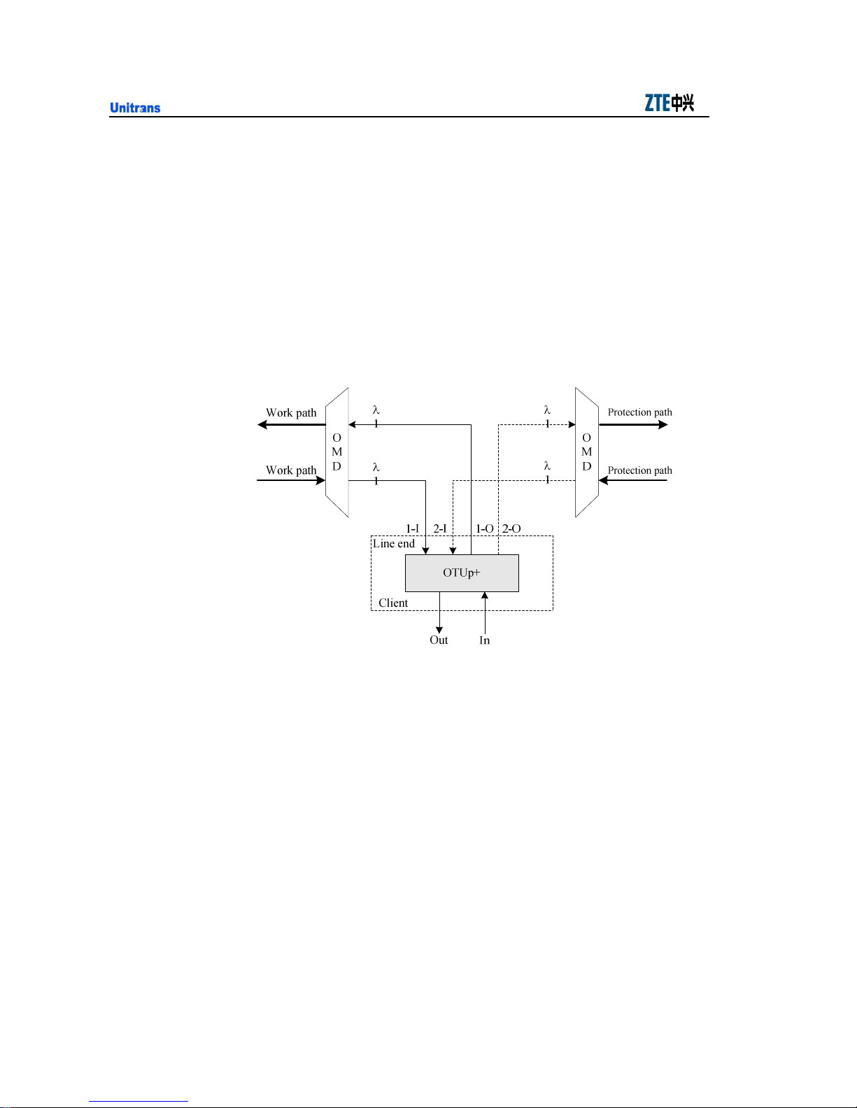
Ring network protection in the ZXMP M600 indicates channel 1+1 protection. It is
implemented by an OTU with the protection function. The working principle of this
protection in a single node is shown in Fig. 3.7-1.
Fig. 3.7-1 1+1 Protection of Optical Channel on a Ring Network
OTUp+ board is an OTU with the protection function. It provides one interface at the
client and two at the line end.
The switch criteria are the LOS signal of receiving module.
The switch operation is achieved by electrical cross switch chip.
3-8
Page 55
4 System Configurations and Networking
Modes
This chapter deals with the system configurations and networking modes of the ZXMP
M600 and illustrates the application of the ZXMP M600 through a configuration
example.
4.1 System Configuration
4.1.1 Board Slot Resources
The ZXMP M600 equipment includes a CWU shelf and SMU shelf. The board slot
resources of the two shelves are respectively described below. Each node configures 7
subracks of 1U height maximum. The configuration includes at least one CWU for
NCP, for example, 4 CWU and 3 SMU or 1 CWU and 6 SMU.
4.1.1.1 CWU Shelf
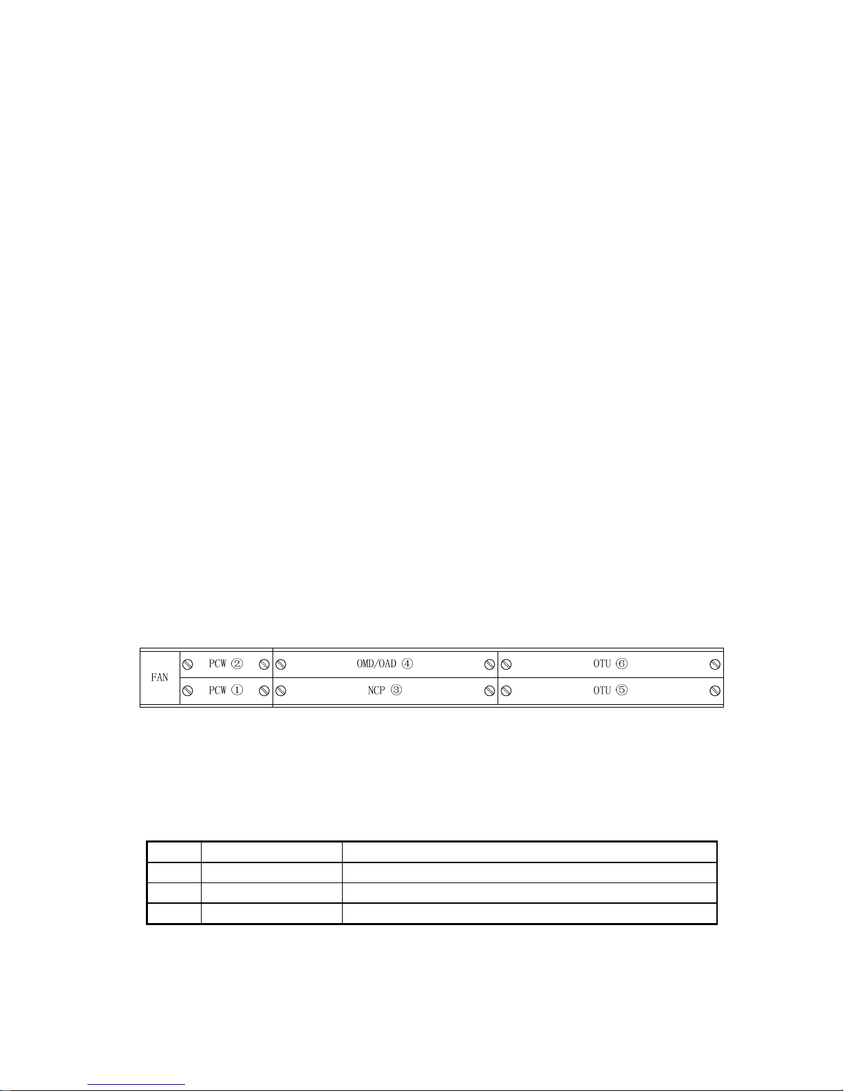
The distribution of the slots in the CWU shelf is shown in Fig. 4.1-1. The figures here
indicate the slot numbers.
Fig. 4.1-1 Slot Distribution in the CWU Shelf
The relation between the boards and the slots is shown in Table 4.1-1.
Table 4.1-1 Relation between the Boards and Slots in the CWU Shelf
Slot No. Boards that can be Inserted Remarks
1, 2 PCW Each PCWAS occupies one slot.
3 NCP Only configured in the master CWU shelf of each node and it occupies slot 3.
3, 4, 5, 6 OTU, OMD, OAD Each board can be inserted in any of the slots and it only occupies one slot.
Note: Slot 3 can be used when NCP is not present.
4-1
Page 56
ZXMP M600 (V1.0) Technical Manual
4.1.1.2 SMU Shelf
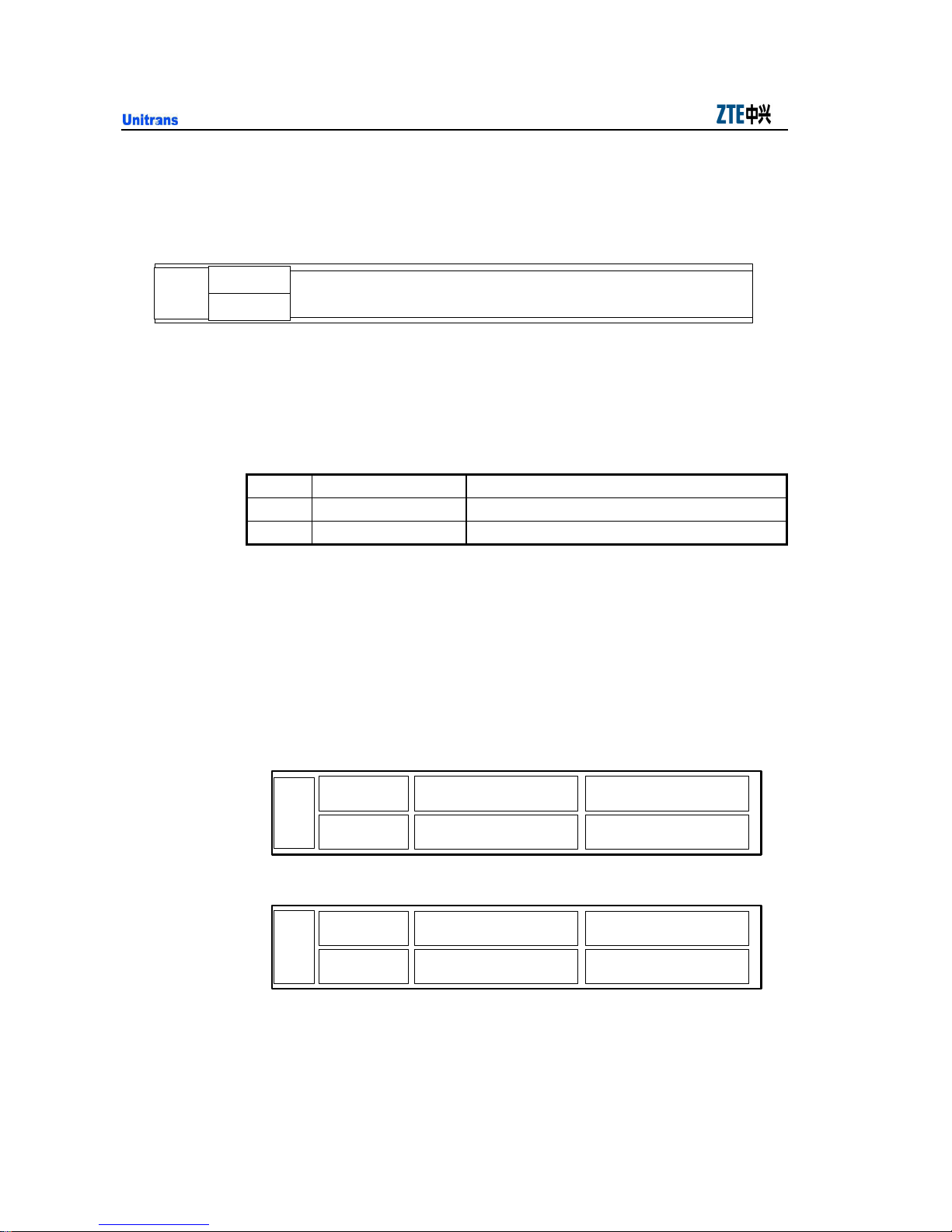
The distribution of the slots in the SMU shelf is shown in Fig. 4.1-2. The figures here
indicate the slot numbers.
FAN
PCW ②
SRM42/GEM2 ③
PCW ①
Fig. 4.1-2 Slot Distribution in the SMU Shelf
The relation between the boards and the slots is shown in Table 4.1-2.
Table 4.1-2 Relation between the Boards and Slots in the SMU Shelf
Slot No. Boards that can be Inserted Remarks
1, 2 PCW Each PCWAS occupies one slot.
3 SRM42, GEM2 ——
4.1.2 Metro Optical Terminal Equipment (OTM)
OTM is used as a terminal node of a line to add/drop all services. Its functional
structure is shown in Fig. 1.2-2.
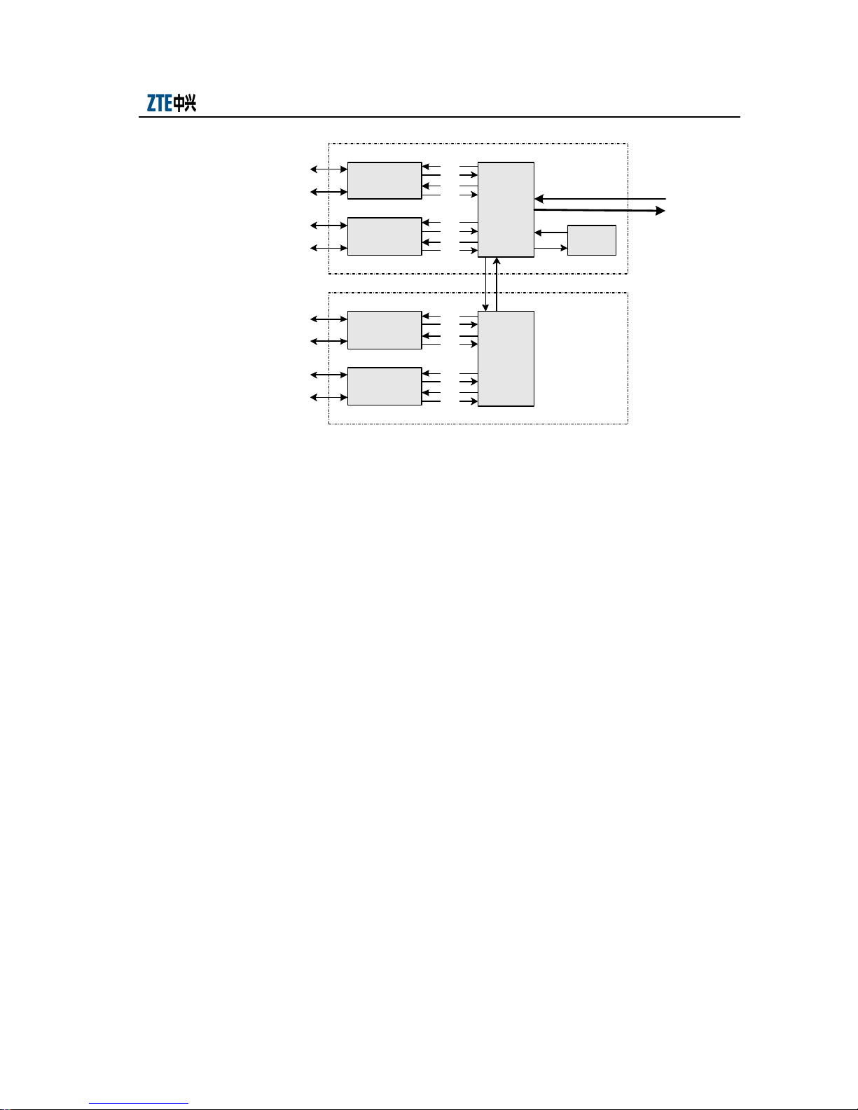
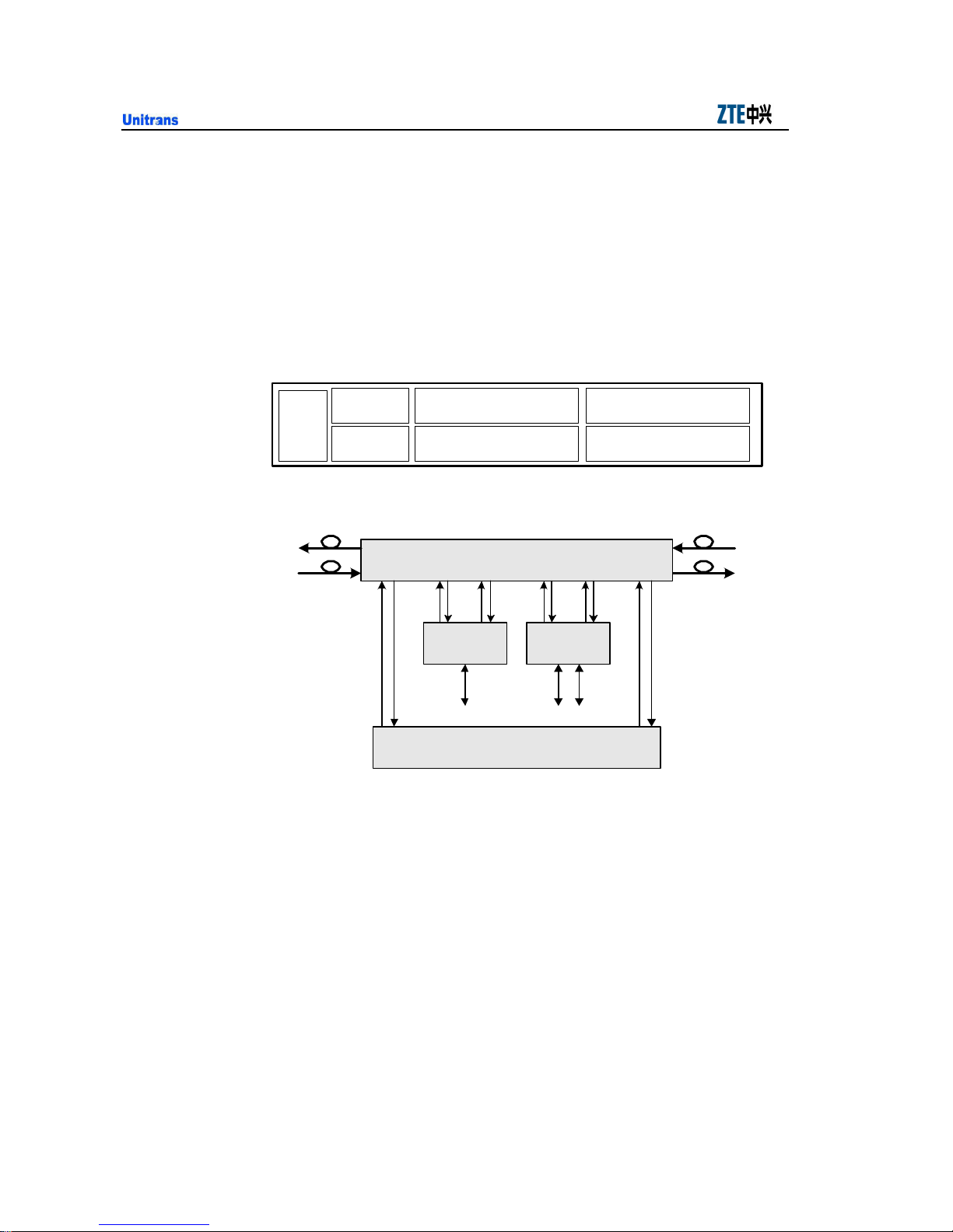
Take the OTM that adds/drops 8 wavelengths at the terminal for example. The board
configuration of the OTM is shown in Fig. 4.1-3, while the fiber connection is shown
in Fig. 4.1-4.
FAN
FAN
Fig. 4.1-3 Board Configuration of OTM Equipment (which adds/drops 8 wavelengths)
PCWAS
PCWAS
PCWAS
PCWAS
2
1
Slave CWU shelf
2
1
Master CWU shelf
4-2
OMD4-5 OTU
OMD5-1
NCP
4 6
3
4 6
3
OTU
OTU
OTU
5
5
Page 57
Chapter 4 System Configurations and Networking Modes
Master CWU
OTU1
OTU2
CH1
CH2
CH3
CH4
LINE IN
OM D5-1
LINE OUT
NCP
CH0
UPG
OTU3
CH5
CH6
OM D4-5
OTU4
CH7
CH8
Slave CWU
CH1~CH8: opt ical interface of multiplexin g/ demultiplex ing channel on
OMD board, CH1=147 1nm, int erv al=20n m
CH0: 13 10 nm monit or channel int erf ace o n OMD5-1, which is
connect ed to t he OSC int erface of t he NCP board
UPG: upgrade int erface of OMD board
LINE IN/LINE OUT : op tical line input/ output inter face of OMD board
Fig. 4.1-4 Fiber Connection of OTM Equipment (1310nm monitoring channel)
Configuration description
1. In Fig. 4.1-3, PCWAS boards are adopted to provide -48V DC power input for
the system ddl.
2. In this configuration 2-channel bidirectional OTU boards are adopted. Other
types of OTU boards can also be used as required.
3. The monitoring channel is the 1310nm channel. Therefore, the CWU shelf is
4. If the ZXMP M600 needs to implement the multiplexing function, for a certain
configured with an OMD5-1 board to provide an interface for the 1310nm
channel. If the monitoring channel is 1510nm. The CH3 interface of the
OMD5-1 board should be connected with the OSC interface of the NCP board.
wavelength, a multiplexing board (SRM42 or GEM2) can be used without OTU.
In addition, an SMU shelf should be added for installing the multiplexing board.
4-3
Page 58
ZXMP M600 (V1.0) Technical Manual
4.1.3 Metro OADM Equipment (OADM)
OADM is used as a node in the middle of the line to add/drop some services. Other
services are directly connected. The functional structure of OADM is shown in Fig.
1.2-3.
Take the OADM that adds/drops 3 wavelengths for example. The board configuration
of the OADM node is shown in Fig. 4.1-5, while the fiber connection is shown in Fig.
4.1-6.
PCWAS
FAN
PCWAS
Fig. 4.1-5 Board Configuration of OADM Equipment (which adds/drops 3 wavelengths)
2
1
ABLine BALine
ABch1 ABch3ABch2
ABLine, ABchn: AB line, channel interface
BALine, BAchn: BA line, channel interface
OAD3
NCP
OAD
BAch2
OTU1 OTU2
NCP
4 6
3
OTU
OTU
BAch3 BAch1
5
Fig. 4.1-6 Fiber Connections of OADM (which adds/drops 3 wavelengths)
Configuration description:
1. In Fig. 4.1-5, PCWAS boards are adopted to provide -48V DC power input for
the system.
2. This configuration is suitable for adding/dropping 3 wavelengths. A_AD1 and
B_AD1 are monitoring channels connecting to AOSC and BOSC on the NCP
board respectively. 1310nm or 1510nm can be chosen as their wavelength.
4-4
Page 59
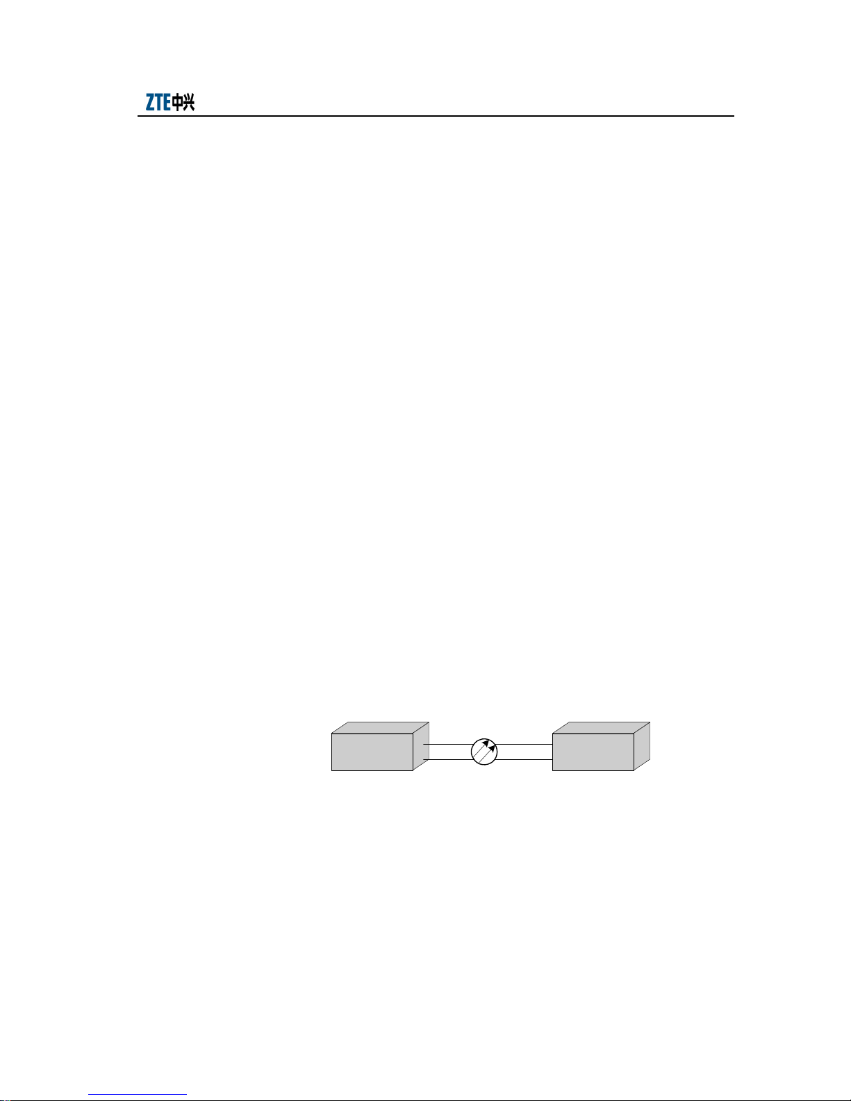
Chapter 4 System Configurations and Networking Modes
3. If the 1310nm monitoring channel is not used, as shown in Fig. 4.1-6, the 1310
nm channel can be used as a service add/drop channel.
4. To add/drop 1 wavelength, use OAD1; to add/drop 2 wavelengths, use OAD2; to
add/drop 3 wavelengths, use OAD3 as shown in Fig. 4.1-6. To add/drop more
than 3 wavelengths, OAD and OMD boards can be cascaded to implement the
multiplexing/ demultiplexing function.
5. As shown in Fig. 4.1-6, OTU1 is an OTU with the protection function (that is,
OTUp). It implements 1+1 channel protection based on the ring network. Other
types of OTU boards can also be used as required.
6. If the ZXMP M600 needs to implement the multiplexing function, for a certain
wavelength as shown in Fig. 4.1-6, a multiplexing board (SRM42 or GEM2) can
be used to replace the OTU board. In addition, an SMU shelf should be added
for installing the multiplexing board.
4.2 Networking Mode
The ZXMP M600 can be configured as OTM equipment and OADM equipment to
implement multiple networking modes with various functions and to meet different
levels of networking demands. The networking modes will be briefly introduced in the
following.
4.2.1 Point-to-point Networking
The application of point-to-point networking is shown in Fig. 4.2-1.
OTM OTM
Fig. 4.2-1 Application of Point-to-point Networking
4-5
Page 60
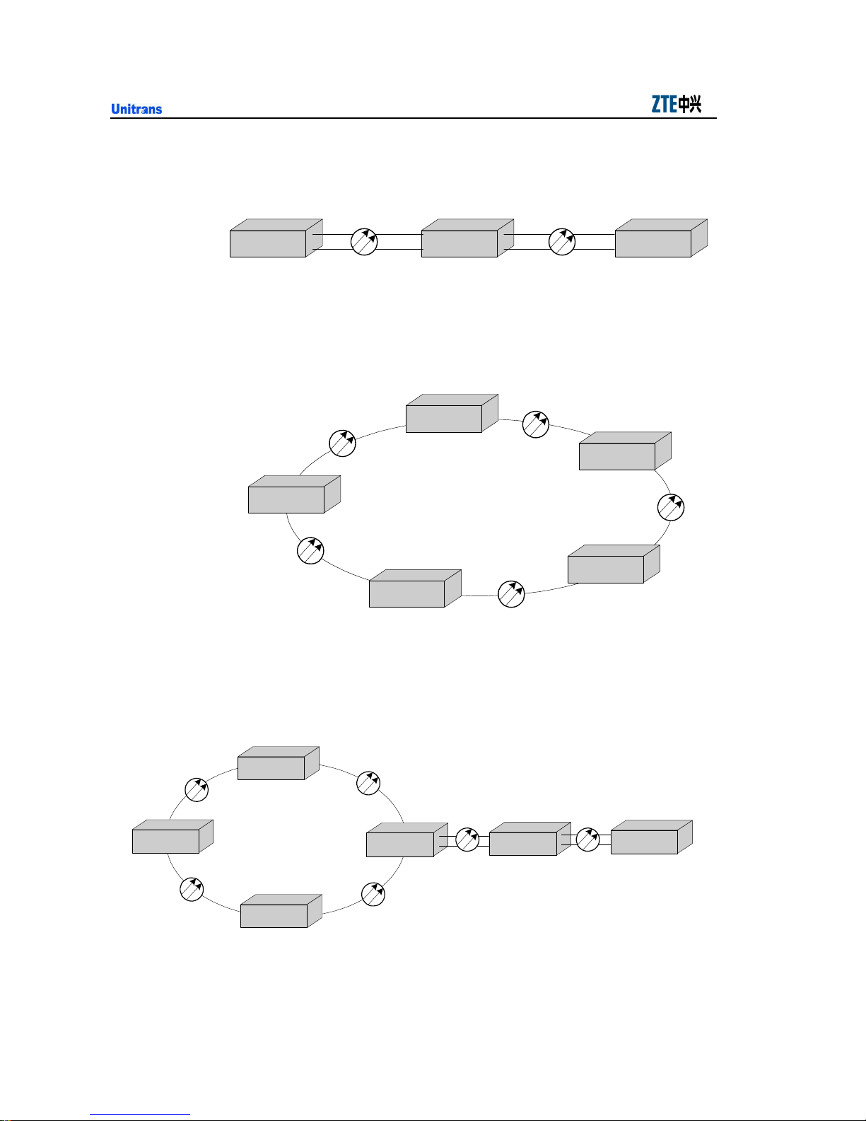
ZXMP M600 (V1.0) Technical Manual
4.2.2 Chain Networking
The application of chain networking is shown in Fig. 4.2-2.
OTM OADM OTM
4.2.3 Ring Networking
The application of ring networking is shown in Fig. 4.2-3.
OADM
Fig. 4.2-2 Application of Chain Networking
OADM
OADM
4.2.4 Ring-to-chain Networking
The application of ring-to-chain networking is shown in Fig. 4.2-4.
OADM
OADM
OADM
Fig. 4.2-4 Application of Ring-to-chain Networking
OADM
Fig. 4.2-3 Application of Ring Networking
OADM
OADM
OADM
OTM
4-6
Page 61
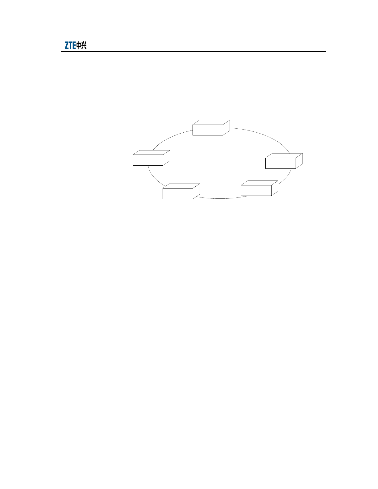
Chapter 4 System Configurations and Networking Modes
4.3 Configuration Example
In the following, a typical configuration example will be introduced, in which the
OADM is used for networking. The network topology is a two-fiber bidirectional ring
network, as shown in Fig. 4.3-1.
A
15km
B
5km
C
18km
20km
E
2km
D
Fig. 4.3-1 Networking in a Typical Configuration Example
This network forms an 8+1 wavelength 5-node ring. The perimeter of the ring is 60km
and the interval between nodes is shown in Fig. 4.3-1. Multiplexing service distribution
is adopted here.
1. Multiplexing node: A; number of wavelengths: 8+1, where “+1” indicates the
1310nm channel.
2. Access nodes: B, C, D, E; number of wavelengths: 2+1, where “+1” indicates
the 1310nm channel.
3. Monitoring channel: 1310nm
4. Service requirements: The service requirements of the nodes in the ring network
are shown in Fig. 4.3-2.
4-7
Page 62
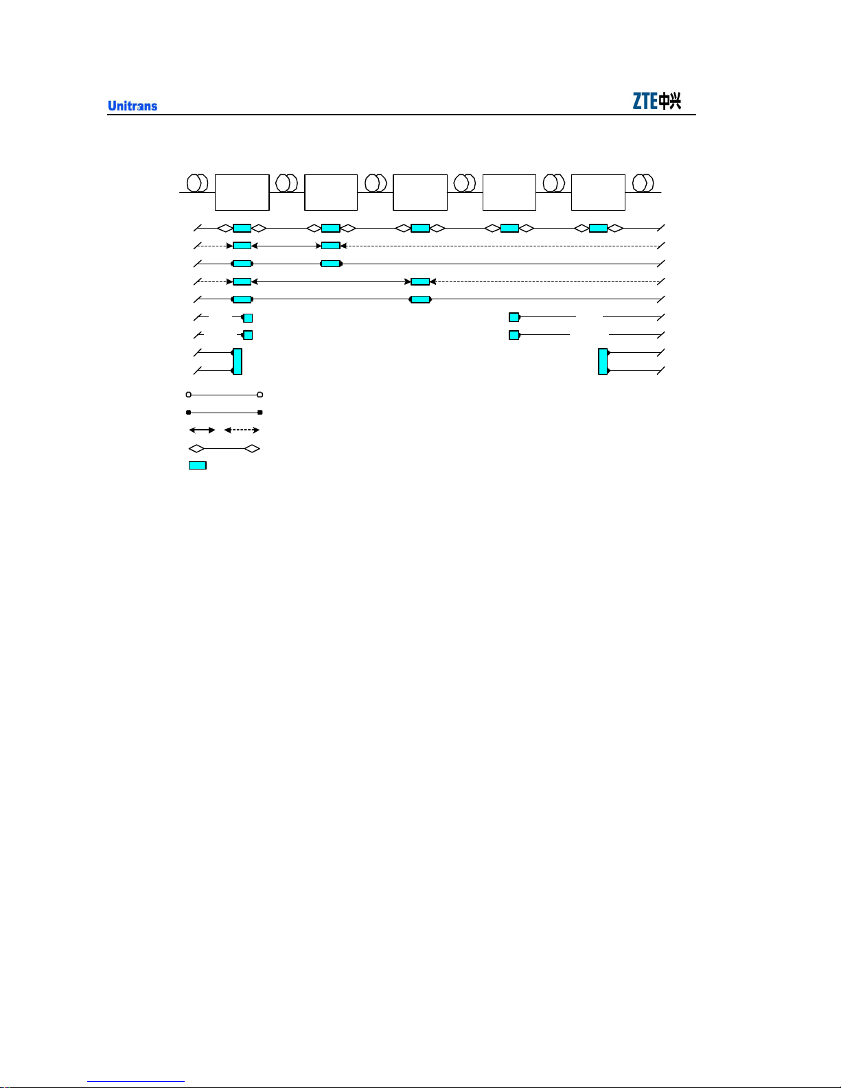
ZXMP M600 (V1.0) Technical Manual
8+1 wave
Add/drop
Node: E
1311 window
1471(1)
1491(2)
1511(3)
1531(4)
1551(5)
1571(6)
1591(7)
1611(8)
Legend:
2xGE
4x622 M
2+1 wave
Add/drop
15km 18km 20km5km
BA C D
osc osc osc osc oscosc
Integrated access without OTU
Configure OTU
Configure OTUP (with p rotected OUT; dotted line indicat ing the protection route)
Op tical monitor
One board
Fig. 4.3-2 Service Requirements
2+1 wave
Add/drop
2+1 wave
Add/drop
4.3.1 Configuration Implementation
2km
2+1 wave
Add/drop
2xGE
4x622 M
4.3.1.1 Configuration Description
According to the service requirements in Fig. 4.3-2, the required boards are analyzed as
follows:
1. NCP board
One NCP board should be configured for each node and be installed in the
master CWU shelf.
As the ZXMP M600 is configured as OADM equipment in the global network
and the monitoring channel is 1310nm, NCP board of which the monitoring
channel type is line and the wavelength is 1310nm should be configured in each
node.
2. PCW board
Two same PCW boards will be configured for each shelf according to the type
of DC power supply equipped in the machine room.
4-8
Page 63

Chapter 4 System Configurations and Networking Modes
3. OMD board
To add/drop 8+1 wavelengths at Node A, OMD5-1 and OMD4-5 boards should
be used together. Two OMD5-1 boards should be configured to implement
transceiving in two optical line directions.
4. OAD board
OAD3 boards should be configured to add/drop 2+1 wavelengths at Nodes B, C,
D and E, to directly connect 2 wavelengths at Nodes B, C and D, and to directly
connect 6 wavelengths at Node E. The wavelengths to be added/dropped on the
OAD3 boards should be determined according to the requirements as shown in
Fig. 4.3-2.
5. OTUq board
OTUq boards should be configured at Nodes B, C and E as each node need to
transfer two channels of services. The two channels of services in Nodes B and
C occupy the same wavelength though they are in different transmission
directions. The two channels of services in Node E occupy different
wavelengths.
Based on the transmission distance, the optical module of the OTUq boards
should be selected to transfer the wavelengths.
6. OTUp+ board
Nodes B and C each use a wavelength to implement 1+1 channel protection.
Therefore, OTUp+ boards should be configured.
Based on the transmission distance, the optical module of the OTUp+ boards
should be selected to transfer the wavelengths.
7. GEM2 and SRM42 boards
Node D uses two channels of wavelengths for two types of multiplexing services:
GEM2 board is used for GbE service while SRM42 board is used for 622Mbit/s
service.
8. Shelves
The number of shelves to be installed in each node should be determined
according to the types and quantity of the services to be implemented.
4-9
Page 64

ZXMP M600 (V1.0) Technical Manual
channel bidirectional)
4.3.1.2 Equipment Configuration
Based on the service requirements as shown in Fig. 4.3-2, the configurations of the
nodes are shown in Table 4.3-1.
Table 4.3-1 Equipment Configuration
Configuration Type
CWU shelf 3 1 1 1 1
SMU shelf 2 —— —— 2 ——
NCP 1 1 1 1 1
PCWAS 10 2 2 6 2
OMD5-1 2 —— —— —— ——
OMD4-5 1 —— —— —— ——
OAD3 —— 1 1 1 1
OTUq (two-
OTUp+(single-channel
protection)
SRM42 1 —— —— 1 ——
GEM2 1 —— —— 1 ——
4.3.2 Application Features
1. When ordinary fibers are used, the ZXMP M600 can implement 8+1 wavelength
service in a single node. In this case, the 1310nm wavelength can transmit both
monitoring service and general services.
Configuration Quantity
A B C D E
3 1 1 —— 1
2 1 1 —— ——
2. The ZXMP M600 can access multiple services such as STM-N and ATM
services. It can also implement the multiplexing function from low rate to high
rate and improve the bandwidth.
3. When configured with an OTU board with the protection function (that is,
OTUp+), the ZXMP M600 can implement 1+1 channel protection to guarantee
network security.
4. As the ZXMP M600 does not support optical power amplification, its
requirement for optical parts such as laser is lower than that of DWDM
equipment. In addition, it features compact structure and flexible configuration
and is suitable for different spans of LAN and MAN.
4-10
Page 65

Appendix A Term Description
A.1 G.652 Optical Fiber
G.652 single-mode optical fiber can be applied to 1300nm and 1550
wavelengths. When it is applied to 1300nm wavelength, the dispersion is about
zero. Therefore, it is the optimum single-mode optical fiber.
The nominal value of the mode field diameter of G652 single-mode fiber is
between 9 µm ~10 µm (the mode field diameter is a parameter unique to
single-mode fibers; it describes the distribution of the optical signals in the fiber
core). The cut-off wavelength λC of the fiber conforms to the 1100nm<λC<1280
nm requirement in the 1300nm wavelength window (it describes the optical
wavelengths that can be transmitted in the single-mode optical fibers). Moreover,
the outer diameter of the cladding area of the single-mode diameter is 125 µm
±3 µm, while the attenuation coefficient is less than 1.0dB/km (for 1300 nm
wavelength area) or less than 0.5dB/km (for 1550 nm wavelength area).
At present, G.652 single-mode optical fibers that can be used for the SDH
development include G.652 A, G.652 B and G.652 C&D.
1) G.652 A: It is applicable to a system lower than G.957, G.691 STM-16. It
supports the single-channel SDH transmission system at the 2.5Gbit/s or a lower
rate and has no special requirement for the PMD coefficient of the intra-cable
fiber.
2) G.652 B: It is applicable to a system higher than G.957 and G.691 STM-16 and it
supports 10Gbit/s and, in some cases, 40Gbit/s transmission systems. Generally
it is required that the PMD coefficient of intra-cable fiber should be less than
0.5ps/km1/2.
3) G.652 C&D: It is applicable to a system lower than G.957, G.691 and G.692
STM-16 and can be full-wave optical fiber. For the detailed description of this
type, please refer to “full-wave optical fiber”.
A-1
Page 66

ZXMP M600 (V1.0) Technical Manual
G.652A and G.652 B single-mode optical fibers, that is, the ordinary fibers
mentioned above have a large dispersion at 1530nm~1565nm of Band C and
1565nm~1625nm of Band L, which is generally 17ps/nm·km~22ps/nm·km.
When the system rate is 2.5Gbit/s or higher, dispersion compensation is required.
G.652A and G.652 B fibers are widely applied in transmission networks at
present.
A.2 Full-wave Fiber
Full-wave fiber is numbered as G.652 C&D in ITU-T Recommendations. It is
one kind of G.652 fiber. Its full name is wavelength-expanded non-dispersion
single-mode shifted fiber.
The full-wave optical fiber eliminates OH- ions near the 1385nm wavelength and
thus also eliminates the appended peak attenuation caused by the OH- ions. Thus,
the fiber attenuation is only determined by the internal scattering loss of the
silicon glass.
The attenuation of the full-wave fiber becomes even at the band of
1310nm~1600nm. As internal OH- ions are already eliminated, no peak
attenuation will occur even when the fiber is exposed to hydrogen gas and the
long-term attenuation is reliable. Except that there is no peak attenuation,
full-wave fiber is the same as the ordinary standard G.652 clad optical fibers.
Full-wave optical fiber can provide a complete transmission band from 1280nm
to 1625nm. The available wavelength range is about 1.5 times of the wavelength
range of ordinary fibers.
A-2
Page 67

................... Appendix A Term Description
A.3 Working Wavelength
The working principle of WDM is to multiplex multiple optical channel signals
into one fiber for transmission and implement the reverse process. Therefore, to
allocate channels efficiently in a limited wavelength area, improve the
bandwidth utility and reduce the non-linear effects between adjacent channels,
the working wavelengths of the multiplex optical channel signals should be
specified strictly.
1. DWDM system
As EDFA is used to amplify optical signals, the working wavelength range is
restricted by the amplification range of EDFA, which is 1530nm~1565nm.
However. According to ITU-T Recommendation G.692, the working wavelength
range of the DWDM system is 1528.77nm~1560.61nm and the corresponding
working frequency range is 196.1THz~192.1THz.
2. CWDM system
In the CWDM system, EDFA technique is not used as the transmission distance
is relatively short. The working wavelength range of the CWDM system is
determined by the fibers used. If ordinary fibers, that is, G.652 A&B fibers are
adopted, the working wavelength range is 1471nm~1611nm. If G.652 C&D
full-wave optical fibers are adopted, the working wavelength range is
1271nm~1611nm.
A-3
Page 68

ZXMP M600 (V1.0) Technical Manual
A.4 Channel Interval
It refers to the nominal frequency difference (wavelength interval) between two
adjacent multiplex channels.
Channel intervals can be either even or uneven. Uneven channel intervals can be
used to suppress the Four Wave Mixing (FWM) effect of G.653 fiber. At present,
however, even channel intervals are used in most cases.
ITU-T Recommendation G.692 specifies that the channel interval of DWDM
system should be an integer multiple of 100GHz (about 0.8nm). At present,
generally two channel interval standards are used, that is, 200GHz (about 1.6nm)
and 100GHz (0.8nm).
IUT-T Recommendation G.694.2 specifies that the channel interval of the
CWDM system should be 20nm.
A.5 Central Wavelength or Central Frequency
It indicates the central wavelength or frequency to which each multiplex channel
in the WDM system corresponds.
The frequency criterion is used in the DWDM system. The working frequency
range of the system is 196.1THz~192.1THz. When the channel interval is
0.1THz, the corresponding central frequencies are 196.1THz, 196.2THz and so
on. When the channel interval is 0.2THz, the corresponding central frequencies
are 196.1THz, 196.3THz and so on.
Wavelength criterion is used for the CWDM system. If G.652 A or G.652 B
fibers are used, the central wavelengths are respectively 1471nm, 1491nm,
1511nm, 1531nm, 1551nm, 1571nm, 1591nm and 1611nm. If full-wave fibers
are used, the wavelength range is 1271nm~1611nm and the interval is 20nm,
then the central wavelengths are respectively 1271nm, 1291nm and so on.
A-4
Page 69

................... Appendix A Term Description
A.6 Channel Bandwidth
It is a parameter of a demultiplexer. A demultiplexer includes two kinds of
bandwidth: channel bandwidth @-0.5dB and channel bandwidth @-20dB. They
respectively indicate the change value of the corresponding working wavelength
when the insertion loss of the demultiplexer decreases for 0.5dB and 20dB.
1. Bandwidth @-0.5dB: It describes the band pass performance of the
demultiplexer. A good band pass performance curve should be even and broad.
The greater the bandwidth is, the better the performance.
2. Bandwidth @-20dB: It describes the stopband performance of the demultiplexer.
The stopband performance curve should be steep. The greater the bandwidth is,
the better the performance.
The central wavelengths of CWDM filter in the case of channel bandwidth
@-0.5dB end in “1”. The channel interval is 20nm and the precision is ±6.5nm.
When ordinary optical fibers are used, the bandwidth of the wavelengths are
respectively 1471±6.5nm, 1491±6.5nm, 1511nm±6.5nm, 1531nm±6.5nm,
1551nm±6.5nm, 1571nm±6.5nm, 1591nm±6.5nm and 1611nm±6.5nm.
A.7 Insertion Loss
Insertion loss indicates the attenuation of the optical signals caused by the WDM
equipment. It directly affects the transmission distance of the WDM system.
It is the ratio between the optical power of the input port and that of the output
port in the equipment. The formula for calculating it is as below:
IL=-10
In the formula, Pi indicates the optical power transmitted to the input pot, while
Po indicates the optical power received from the output port.
log
(Pi/Po)
A-5
Page 70

ZXMP M600 (V1.0) Technical Manual
A.8 Isolation
It is a parameter of the demultiplexer and indicates the separation of the
multiplex optical channel signals from the demultiplexer.
The higher the channel isolation is, the better the frequency selection
performance of the WDM equipment. Consequently, the crosstalk suppression
ratio becomes higher and the mutual interference between multiplex optical
channels becomes lower.
Channel isolation includes adjacent channel isolation and non-adjacent channel
isolation.
1. Adjacent channel isolation
It is the ratio between the output optical power of an optical channel and the leak
optical power on this channel from an adjacent optical channel signals that has
the same output power.
It indicates the isolation of the demultiplexer from the two adjacent multiplex
optical channel signals.
2. Non-adjacent channel isolation
It is the ratio between the output optical power of an optical channel and the leak
optical power on this channel from a non-adjacent optical channel.
It indicates the isolation of the demultiplexer from the non-adjacent multiplex
optical channel signals.
A-6
Page 71
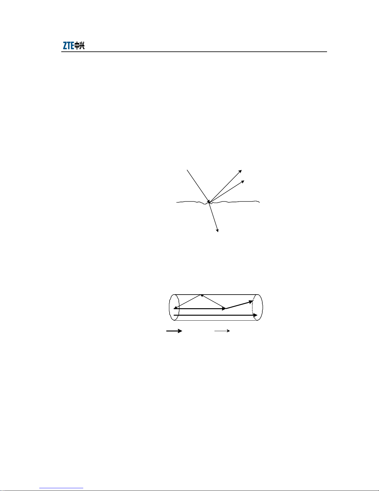
................... Appendix A Term Description
A.9 Reflection
1. Concept
When light is transmitted over an interface made of different media, it will be
reflected and refracted. If the interface is made of uneven media, the reflection
(dispersion) will be very complicated and may exist on different levels. In the
optical channel, it is in the form of reversely transmitted wave, that is, reflection,
which is shown in Fig. A.9-1.
Forward wave
n1
n2
Refracted wave
Reflected wave
Fig. A.9-1 Optical Transmission Over Interface Made of Uneven Media
As the optical fiber is not made of ideal even medium, the practical transmission
over the fiber is as shown in Fig. A.9-2.
Forward wave Reflected wave
Fig. A.9-2 Optical Dispersion Over a Fiber
2. Causes
The reflection may be attributed to the following causes: Rayleigh reflection
caused by Rayleigh dispersion, Stokes reflection caused by Brillouin dispersion,
optical coupling generated at the connection points of optical parts or optical
fibers and reflection caused by multiple interfaces due to optical fiber crackle.
A-7
Page 72

ZXMP M600 (V1.0) Technical Manual
3. Influence on the system
A.10 Return Loss
The Rayleigh reflection exerts least influence, while Stokes reflection only
occurs at the excitation threshold.
Large reflection may seriously affect the transmission system and produce bit
error, delay and pulse expansion in the signals. If the reflection produces noise,
it will lower the signal-noise ratio and affect the normal operation of the system.
It describes the reflection restriction index of the interface that is used to restrict
the reflection strength in the optical interface on an optical channel.
Optical Return Loss (ORL) is defined as the ratio between the power of the
forward optical signals and the power of the reverse optical reflection at a
specific point.
It can be calculated through the following formula:
IL=10 lg (Ps/PR) (dB)
In the formula, Ps indicates the power of forward optical signals while P
indicates the power of the reverse optical reflection.
A.11 Side Mode Suppression Ratio
It is the ratio between the major mode optical power of the optical source in full
modulation (the peak value) and the maximum side mode optical power
(secondary peak value) under the worst reflection condition. It is only valid to a
laser that supports direct modulation.
A.12 Minimum Extinction Ratio
It indicates the ratio between the average high (on) optical power and the
average low (off) optical power in full modulation under the worst reflection
condition.
R
A-8
Page 73

................... Appendix A Term Description
A.13 Maximum -20dB Bandwidth
Maximum -20dB bandwidth is a parameter of a Single Longitudinal Mode
(SLM) laser, the unit being nm. It indicates the optical bandwidth when the peak
wavelength decreases for 20dB
A.14 Dispersion Tolerance
Dispersion is a transmission property of optical fibers. As optical pulses with
different wavelengths are transmitted at different rates over an optical fiber, the
dispersion shows the expansion of the optical pulse when transmitted over
optical fibers.
Pulse expansion will cause overlapping of the pulse codes transmitted through
digital communication over optical fibers, that is, inter-code interference will
occur. This will result in bit errors. To avoid bit errors, the pulse interval must be
extended, which will lower the transmission rate and consequently reduce the
communication capacity. On the other hand, the pulse expansion will become
increasingly serious with the increase of the transmission distance.
As the optical parts of the WDM system will be greatly affected by the
dispersion, there is a maximum dispersion value that the WDM system can
tolerate. This is called dispersion tolerance. The system can implement normal
transmission only when the dispersion tolerance is not exceeded.
A-9
Page 74

Page 75

Appendix B Abbreviations
AFR Absolute Frequency Reference
AGENT
AIS Alarm Indication Signal
ASE Amplified Spontaneous Emission
BER Bit Error Ratio
CDR Clock and Data Recovery
CMI Code Mark Inversion
CPU Center Process Unit
CRC Cyclic Redundancy Check
CWDM Coarse Wavelength Division Multiplexing
CWU CWDM Unit
DBMS Database Management System
DCC Data Communications Channel
DCN Data Communications Network
DDI Double Defect Indication
DWDM Dense Wavelength Division Multiplexing
DXC Digital Cross-connect
EAM Electrical Absorption Modulation
ECC Embedded Control Channel
EDFA Erbium Doped Fiber Amplifier
ESCON Enterprise System Connection
EX Extinction Ratio
FC Fiber Channel
FDI Forward Defection Indication
FEC Forward Error Correction
FPDC Fiber Passive Dispersion Compensator
FWM Four Wave Mixing
GbE Gigabits Ethernet
GUI Graphical User Interfaces
IP Internet Protocol
LD Laser Diode
LOF Loss of Frame
LOS Loss of Signal
MCU Management and Control Unit
MQW Multiple Quantum Well
B-1
Page 76

ZXMP M600 (V1.0) Technical Manual
MSP Multiplex Section Protection
MST Multiplex Section Termination
MSTP Multi-Service Transport Platform
MTBF Mean Time Between Failure
NCP Net Control Processor
NE Network Element
NNI Network Node Interface
NMCC Network Manage Control Center
NRZ Non Return to Zero
NT Network Termination
OAD Optical Add/Drop Unit
OADM Optical Add/Drop Multiplexer
OCh Optical Channel
OLT Optical Line Termination
OMD Optical Dmux/Mux Unit
OSC Optical Supervisory Channel
OSNR Optical Signal-Noise Ratio
OSPF Open Shortest Path First
OTM Optical Terminal
OTN Optical Transport Network
OTU Optical Transponder Unit
PCW Power for CWDM Unit
POS Packet Over SDH
PSTN Public Switched Telephone Network
SAN Storage Area Network
SDH Synchronous Digital Hierarchy
SEF Severely Errored Frame
SES Severely Errored Block Second
SFF Small Form Factor Transceiver
SFP Small Form Factor Pluggable
SMCC Sub-network Management Control Center
SMU Subrate Multiplexer Unit
SNMP Simple Network Management Protocol
SRM Sub-Rate Multiplexing
STM Synchronous Transfer Mode
STP Spanning Tree Protocol
TCP Transmission Control Protocol
TMN Telecommunications Management Network
WDM Wavelength Division Multiplexing
B-2
 Loading...