

Page 1

ZTE IX380
WiMAX MODEM
User Manual
1
Page 2

2
No part of this publication may be excerpted, reproduced, translated in any
form or by any means, electronic or mechanical, including photocopying and
microlm, without the prior written authorization of ZTE Corporation.
There may be possibility of inconformity between the manual and new pub-
lishing documents, we promise a timely update. No prior notication for the
updated materials but transfer into update version.
Copyright © 2012 by ZTE Corporation
All rights reserved.
Page 3

Contents
1. General .........................................................................6
1.1 Welcome ..........................................................................................6
1.2 Safety Precautions ...........................................................................6
1.3 Cleaning and Maintaining ................................................................ 8
1.4 Limited Warranty ..............................................................................8
1.5 Limitation of Liability .........................................................................9
2. Getting Started ...........................................................10
2.1 Appearance ....................................................................................10
2.2 LED Indicator .................................................................................10
2.3 Working Condition ..........................................................................12
2.4 Technical Parameters ....................................................................
2.5 Ports ...............................................................................................13
3. Connecting MODEM ..................................................14
3.1 Application Structure ......................................................................14
3.2 Hardware Installation .....................................................................14
3.2.1 Connect to LAN ..................................................................14
3.2.2 Connect to Phone...............................................................15
3.2.3 Connect Power Adapter ..................................................... 15
3.2.4 Power on MODEM .............................................................15
3
12
Page 4

4
4. Preparation for Conguring MODEM .......................16
4.1 TCP/IP Installation and Conguration ............................................16
4.2 Checking ........................................................................................19
4.2.1 Check LAN Connection ......................................................19
4.2.2 Cancel Proxy Server in Browser ........................................19
4.2.3 Others.................................................................................20
5. Ordinary Operation ....................................................21
5.1 Login ..............................................................................................21
5.2 Status .............................................................................................24
5.2.1 Connection Status ..............................................................24
5.2.2 WiMAX Information ............................................................26
5.2.3 About My Modem ............................................................... 28
5.3 Setup ..............................................................................................29
5.3.1 IP Conguration ..................................................................29
5.3.2 DHCP Clients ..................................................................... 30
5.3.3 DHCP Binding .................................................................... 31
5.3.4 WAN Connection ................................................................ 32
5.4 WLAN .............................................................................................33
5.4.1 Basic Settings.....................................................................33
5.4.2 Security ..............................................................................35
5.4.3 MAC Filter ..........................................................................38
5.4.4 Advanced Settings .............................................................40
Page 5

5.5 Advanced .......................................................................................41
5.5.1 Routing Setup.....................................................................41
5.5.2 SNTP Client Conguration ................................................. 42
5.5.3 DDNS Setup ....................................................................... 43
5.5.4 DNS Conguration .............................................................44
5.6 Security ..........................................................................................46
5.6.1 Port Forwarding .................................................................. 46
5.6.2 Port Trigger.........................................................................49
5.6.3 DMZ....................................................................................52
5.7 Tools ...............................................................................................54
5.7.1 System Commands ............................................................54
5.7.2 Ping .................................................................................... 55
5.7.3 User Management .............................................................. 56
5.7.4 Update MODEM .................................................................57
5.7.5 System Log ........................................................................58
5.8 WIMAX Settings .............................................................................59
5.8.1 Channel Settings ................................................................59
5.8.2 WiMAX Authentication .......................................................60
6. Troubleshooting .........................................................64
Appendix Glossary ..........................................................67
5
Page 6

6
1. General
1.1 Welcome
Thanks for choosing the ZTE IX380 WiMAX MODEM (hereinafter referred to
as “MODEM”). To get the most from your MODEM and to keep it in the best
condition please read this manual carefully.
The pictures, symbols and contents in this manual are for reference only.
They might not be completely identical with your MODEM. ZTE operates a
policy of continuous development. We reserve the right to update the techni-
cal specications in this document at any time without prior notice.
1.2 Safety Precautions
Some electronic devices may be susceptible to electromagnetic interference.
Locate the MODEM away from TV set, radio and other electronic equipment
to avoid electromagnetic interference.
The MODEM may interfere with medical devices li ke hearing aides and
pacemakers. Consult with a physician or the manufacturer of the medical
device before using the MODEM.
Do not use your MODEM in dangerous environments such as oil or chemical
factories where there are explosive gases or explosive products being pro-
cessed.
Please use original accessories or accessories that are authorized by your
Equipment Provider. Unauthorized accessories may affect the MODEM per-
formance, damage the MODEM or cause danger to you.
Page 7

Do not attempt to dismantle the MODEM. There are no user serviceable
parts.
Do not immerse the MODEM in any liquid.
Do not place objects on top of the MODEM. This may lead to overheating of
the device.
The device must be placed in ventilation environment for use.
Do not expose the MODEM to direct sunlight or store it in hot areas. High
temperature can shorten the life of electronic devices.
Do not touch the antenna while calling.
Do not allow children to play with the MODEM or charger.
Keep the length of the cable between the MODEM and the phone less than
33 feet.
The MODEM is for indoor use only. Do not use the MODEM outside. Do not
connect telephone extensions which run outside of the building. These can
result in lightning damage to your unit.
This device has been tested for compliance with FCC RF Exposure (SAR)
limits in the typical laptop computer conguration. This device cannot be Use
with handheld PDAs (personal digital assistants). This device and its antenna
must not be co-located or operated in conjunction with any other antenna or
transmitter.
7
Page 8

8
1.3 Cleaning and Maintaining
Use an antistatic cloth to clean the MODEM. Do not use chemical or abra-
sive cleanser as these could damage the plastic case. Turn off your MODEM
before you clean it.
Do not use your MODEM during a thunderstorm. Remove the mains power
pack from the wall socket.
Please do not touch the antenna with your hand during conversation. Cover-
ing the antenna may affects call quality, may cause the MODEM to operate
at higher power level than needed.
1.4 Limited Warranty
This warranty does not apply to defects or errors in the Product caused by:
(a) Reasonable MODEM Appearance Disguration.
(b) End User’s failure to follow ZTE’s installation, operation or maintenance
instructions or procedures.
(c) End User’s mishandling, misuse, negligence, or improper installation,
disassemble, storage, servicing or operation of the Product.
(d) Modications or repairs not made by ZTE or a ZTE-certied individual.
(e) Power failures, surges, re, ood, accident, actions of third parties or
other events outside ZTE’s reasonable control.
(f) Usage of products of third Parties, or usage in conjunction with third
party products provided that such defects is due to the combined usage.
Page 9

(g) Any other cause beyond the range of normal usage for Products. End
User shall have no right to reject, return, or receive a refund for any
Product from ZTE under the above-mentioned situations.
This warranty is end user’s sole remedy and ZTE’s sole liability for defec-
tive or nonconforming items, and is in lieu of all other warranties, expressed,
implied or statutory, including but not limited to the implied warranties of mer-
chantability and tness for a particular purpose, unless otherwise required
under the mandatory provisions of the law.
1.5 Limitation of Liability
ZTE shall not be liable for any loss of prots or indirect, special, incidental or
consequential damages resulting from or arising out of or in connection with
using of this product, whether or not ZTE had been advised, knew or should
have known of the possibility of such damages, including, but not limited to
lost prots, interruption of business, cost of capital, cost of substitute facilities
or product, or any downtime cost.
9
Page 10
10
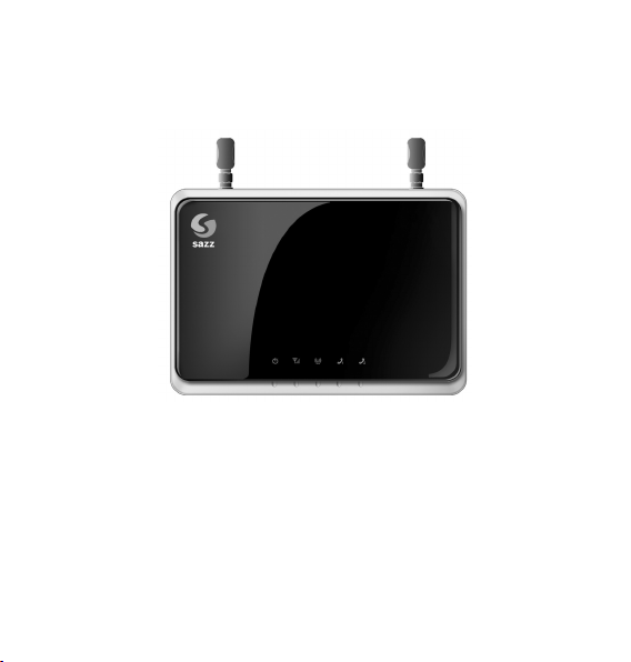
2. Getting Started
2.1 Appearance
Front Panel
2.2 LED Indicator
There are total nine LEDs for the MODEM, detailed description as following
table.
Page 11
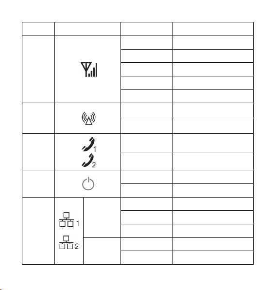
LED Marker Status Description
Flashing Red Network searching
WiMAX
CINR
WiFi
Status
Solid Blue Signal is strong
Solid Green Signal is medium
Solid Red Signal is weak
Off No signal
Green WiFi On
Off WiFi Off
Phone1/
Phone2
Power
LAN1/
LAN2
Top left
corner LED
Top right
corner LED
Off Hook on/Out of Service
Solid Green Hook off
Solid Green Power Supply
Solid Red Power Supply Failure
Off Out of Connection
Solid Green Connection
Flashing Green Data Service Process
Off 10M Interface
Solid Yellow 100M Interface
11
Page 12

12
2.3 Working Condition
Working Condition for Host
Working temperature: 0°C ~ +55°C [32 °F ~ 131 °F]
Working humidity: 10% ~ 85%
Storage temperature: -40°C ~ +70°C [-40 °F ~ 158 °F]
Storage humidity: 5% ~ 95%
2.4 Technical Parameters
Mode of Access
WiMAX Protocol 802.16e(IEEE 802.16-2005)
WiFi protocol IEEE 802.11b & 802.11g
WiMAX Frequency Range 3400MHz~3600MHz
WiFi Frequency Range 2400MHz~2483.5MHz
Dimensions (W×H×D)
Weight About 420 g (Including antenna)
Please refer to the real objects for the related parameters about the charger.
WiMAX (Worldwide Interoperability for Micro-
wave Access)
175 mm×122 mm×35 mm
(Excluding the height of antenna)
Page 13
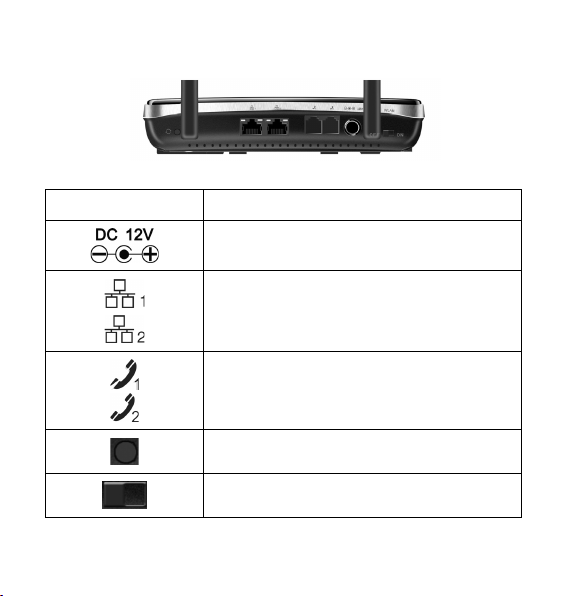
2.5 Ports
All seven ports are in back panel.
Port Indicator Description
External power socket
LAN port
Phone port
Reset button
WLAN button
13
Page 14
14
3. Connecting MODEM
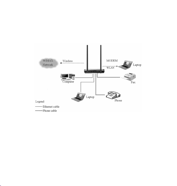
3.1 Application Structure
Network connection is shown as follows:
3.2 Hardware Installation
Make sure that your MODEM is powered off.
You can turn on/off modem by connecting/disconnecting power cable.
3.2.1 Connect to LAN
1. Connect to LAN via Network Cable
Plug one end of an Ethernet network cable into LAN ports on the back of the
MODEM, and plug the other end into an Ethernet port on a network device,
Page 15

for example, PCs or other network devices. The Ethernet cable can be cross-
over or straight.
2. Connect to LAN via WiFi
Enable the WiFi function and make sure that your PC has been installed
wireless network card, and then use your PC to search for the SSID of MO-
DEM to connect with it.
Note:
Don’t insert phone cable into LAN ports.
3.2.2 Connect to Phone
Connect phone cable to or port of MODEM.
3.2.3 Connect Power Adapter
Connect the included power adapter to the MODEM power port, and then
plug the power adapter into an electrical outlet. The Power LED on the front
panel will light up when the adapter is connected properly.
Note:
Make sure you use the power adapter that is supplied with the MODEM. Use
of a different power adapter could damage the MODEM.
3.2.4 Power on MODEM
You can turn on modem by connecting power cable.
15
Page 16

16
4. Preparation for Conguring MODEM
Usually, MODEM has been congured by service provider and you can use it
directly. But in some instance, you need congure MODEM by yourself.
4.1 TCP/IP Installation and Conguration
Installation
If TCP/IP protocol is not installed, please install it rst. Please refer to instal-
lation steps in Windows XP as follows (For classic start menu):
1. Select Start→ Settings→ Control Panel→ Network Connections.
2. Double-click <Local Area Connection> and click <Properties>.
3. Click <Install...> and double-click <Protocol>.
Page 17
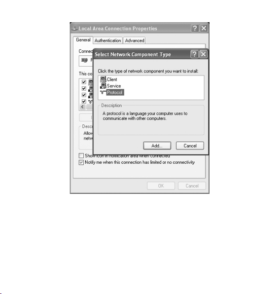
4. Select <
Conguration (For classic start menu)
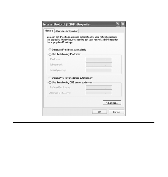
1. Click <Start> and select [Settings], then click <Network Connections>.
2. Double-click <Local Area Connection> and click <Properties>.
3. Do ubl e-c lick <In ter net Protocol (TCP /IP )> and select < Obt ain
Internet Protocol (TCP/IP)> and click <OK>.
an IP address automati cal ly> , <O bta in DNS ser ver add res s
automatically>.
17
Page 18
18
Note:
If the service provider provides DNS IP address, please select <Use the fol-
lowing DNS server addresses> and enter the specied IP address.
Page 19
4.2 Checking
4.2.1 Check LAN Connection
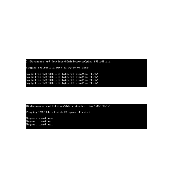
1. Click <Start> and <Run>. In the Open eld, enter command. Press the
Enter key or click the <OK> button. In the command prompt, type ping
192.168.1.1 and press the Enter key.
2. If you get a reply as follows, the LAN connection is ok.
3. If you get a rep ly as fol lows, ple ase c heck the LAN a nd TCP /IP
conguration Refer to chapter 3.2 and chapter 4.1 in detail.
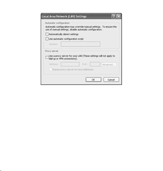
4.2.2 Cancel Proxy Server in Browser
For classic start menu:
1. Select Start→ Settings→ Control Panel→ Internet Options.
2. Select <Connections>.
3. Click the <LAN Settings> button and remove anything that is checked.
19
Page 20
20
4. Click the <
5. Click the <OK> button to conrm canceling proxy server in browser.
Cancel> button to go back to the previous screen.
4.2.3 Others
Sometimes you also need several parameters, please ask your service pro-
vider in detail.
Page 21
5. Ordinary Operation
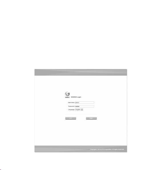
5.1 Login
To access the Web-based Utility of the MODEM, launch Internet Explorer
and enter the MODEM’s default IP address (192.168.1.1) in the address
eld, then press the Enter key. A screen will appear asking you for your User
name and Password (detail as following picture). Enter admin in the User-
name eld and admin in the Password eld. Select the proper language.
Then click the <login> button.
21
Page 22

22
Note:
-If you click <exit> button, you will see the following prompt message.
When you access the MODEM setup page, the rst screen you see as fol-
lowing:
Page 23

The whole interface is divided into two parts, and related functions can be
executed by operation in the related areas.
1. Function Button
Clicking Status link displays status and statistical information for all
connections and interfaces.
Clicking Setup link allows you to edit existing connections, and congure
other basic settings.
Clicking WLAN link allows you to edit WLAN interface.
Clicking Advanced link allows you to congure advanced features like
SNTP, DNS etc.
Clic king Security link allows you to configure Port Forwarding, Port
Trigger etc.
Clicking Tools l ink allows you to carry ou t system commands and
perform simple system tests.
Clicking WiMAX link allows you to congure WiMAX settings.
Clicking logout link to exit MODEM setup page manually.
2. User Area
Show the man-computer interaction information under various conditions.
23
Page 24

24
5.2 Status
5.2.1 Connection Status
After you access the MODEM setup page successfully, please click Status
Connection Status link, you will see the basic information.
WiMAX IP Address
The IP address of the MODEM obtained automatically
Modem IP Address
The IP Address of the MODEM
Page 25

Modem IP Subnet
The IP Subnet of the MODEM
Ethernet 1
LAN port 1 property and current status
Ethernet 2
LAN port 2 property and current status
Phone 1
Phone 1 current status
Phone 2
Phone 2 current status
Show the current network signal strength and connection status. Detail as
follows:
Name Icon Description
Signal
strength
More real lines show stronger signal
No signal
Connected MODEM accesses network successfully
Connection
status
Disconnected Disconnected with WiMAX network
Connecting
MODEM is connecting or searching for
WiMAX network
25
Page 26

26
5.2.2 WiMAX Information
Aft er acce ss MODEM setup page succe ssfu lly, plea se click Status
WiMAX Information link to access the following screen:
Page 27

WiMAX Information
Use to view WiMAX network information.
WAN IP: IP address for WAN connection. It is the same IP address as
the WiMAX IP Address
BSID: Base Station ID of the MODEM connected
Cell ID: Cell ID of the MODEM connected
Frequency: Frequency information
Tx Bytes: Transmission ow statistic
Rx Bytes: Receiver ow statistic
Connection Duration: Duration of time for connection
RSSI: Receive signal strength indicator
Tx Power: Transmission power
PER: Packet error ratio
CINR: Carrier to interference and noise ratio
UL Modulation: Adjustment encoding mode of uplink
DL Modulation: Adjustment encoding mode of downlink
27
Page 28

28
5.2.3 About My Modem
After access MODEM setup page successfully, please click Status About
My Modem link to access the following screen:
Model Name: The model name of this MODEM
Software Version: Current software version of this MODEM
Hardware Version: Current hardware version of this MODEM
Uptime: The running elapsed of the MODEM
MAC Address: The MAC address of the MODEM.
Page 29

5.3 Setup
5.3.1 IP Conguration
After access MODEM setup page successfully, please click Setup LAN
Conguration IP Conguration link to access the following screen:
IP Address: IP address for LAN
NetMask: Net mask for LAN
Enable DHCP: Enable or disable the DHCP service, when this item is
checked, you should set DHCP server information as follows
29
Page 30

30
Start IP: First IP assigned by DHCP server
Max User: The max number assigned by DHCP server
NetMask: Net mask assigned by DHCP server
WINS Server: IP for WINS server
Lease Time: Time that DHCP server rents the IP address (Unit: day)
5.3.2 DHCP Clients
After access MODEM setup page successfully, please click Setup LAN
Conguration DHCP Clients link to access the following screen:
Page 31

MAC Address: MAC address of DHCP client
IP Address: IP address for DHCP clients
Expires in: The left time for lease, if this IP address is static bound, then
demonstrated: Innity
5.3.3 DHCP Binding
After access MODEM setup page successfully, please click Setup LAN
Conguration DHCP Binding link to access the following screen:
You can set MAC address and IP address binding, create a DHCP bind-
ing table to mapping MAC address and IP address of clients. When DHCP
31
Page 32

32
server assigns address, IP address will be assigned according to the binding
relations of MAC and IP, and never expired.
Fo r e xam ple : MAC address i s 0 0-0 a-e 2-c6-48-ba; and IP addre ss is
192.168.1.133, it means that the IP address DHCP Server assigns to the
MAC address corresponding host is 192.168.1.133.
5.3.4 WAN Connection
After access MODEM setup page successfully, please click Setup WAN
Connection link to access the following screen:
Page 33

Type: WAN connection type
NAT: NAT enable/disable
IP address: WAN IP address
Mask: Netmask address
Gateway: Gateway IP address
DNS: Main DNS address
Standby DNS: Standby DNS address
Lease Time: The time that WAN rent IP address from DHCP server
---- <connect>/<disconnect> button Use to WAN connect/disconnect.
5.4 WLAN
5.4.1 Basic Settings
After access MODEM setup page successfully, please click WLAN Basic
Settings link to access the following screen:
33
Page 34

34
Enable Wireless RF: Display the WLAN function status based on the
WLAN button status On or Off.
Mode: Use to select default wireless mode
Channel: Use to congure default wireless channel
SSID: Use to congure SSID, not more than 32 characters
---- <submit> button use to active the basic wireless conguration
Page 35

5.4.2 Security
After access MODEM setup page successfully, please click WLAN Secu-
rity link to access the following screen:
Hide SSID: Select the option to hide SSID of WLAN
Security Mode: Use to select the security mode of WLAN
---- <submit> button use to active the wireless security conguration
35
Page 36

36
WEP
WEP is a basic type of wireless encryption protocol.
WEP Type: You can select the 64-bit or 128-bit, the 128-bit can provide
much better security than 64-bit.
WEP Key Type: You can select Alphanumeric or Hexadecimal.
Use WEP Type: You can select 1~4 to use the Key1~Key4.
Key1~Key4: You can set the WEP key.
---- <submit> button use to active the wireless security conguration
Page 37

WPA
WPA is an advanced type of wireless encryption protocol.
WPA Type: You can select WPA or WPA2.
Encryption Type: You can select TKIP or AES.
Group Key Renewal: You can input 0~3600 seconds as the interval of
change the key.
PSK Passphrase: You can input 8~32 bytes digit as the WPA key.
---- <submit> button use to active the wireless security conguration
37
Page 38

38
5.4.3 MAC Filter
After access MODEM setup page successfully, please click WLAN MAC
Filter link to access the following screen:
Page 39

Access List
Access Restriction: To enable or disable the access restriction function
Restriction Type: If Access Restriction enabled, you need select the
restriction type
---- <submit> button use to active the conguration
Clients MAC
Wireless Clients MAC List: The wireless clients MAC address list.
39
Page 40

40
5.4.4 Advanced Settings
After access MODEM setup page successfully, please click WLAN Ad-
vanced Settings link to access the following screen:
Zone: Use to select Zone
Beacon Interval: Use to congure beacon interval
Tx Rate: Use to congure transmit rate
Tx Power: Use to congure transmit power
---- <submit> button used to active the advanced conguration.
Page 41

5.5 Advanced
5.5.1 Routing Setup
After access MODEM setup page successfully, please click Advanced
Route link to access the following screen:
Default Gateway Interface: Use to congure default gateway interface
Destination Network Address: Use to congure destination network
address
Destination Mask: Use to congure destination network mask address
41
Page 42

42
Next Hop IP: Use to congure next hop IP address
---- <submit> button Use to active the default gateway conguration
add> button Use to save the route item
---- <
---- <modify> button Use to modify the selected route item
---- <delete> button Use to delete the selected route item
5.5.2 SNTP Client Conguration
After access MODEM setup page successfully, please click Advanced
SNTP link to access the following screen:
Automatically adjust clock for daylight saving changes: Enable/
Page 43

Disable automatically adjust clock for daylight saving changes function
Time Zone: Select time zone
Primary Server Address: Main SNTP server address
Secondary Server Address: Standby SNTP server address
Poll Interval: Poll interval time, and the unit is second
---- <submit> button Use to active the SNTP client conguration
5.5.3 DDNS Setup
After access MODEM setup page successfully, please click Advanced
DDNS link to access the following screen:
43
Page 44

44
DDNS is a dynamic domain analysis system. After applying DDNS, a dy-
namic IP address to the mainframe also can provide domain name services.
For example, the mainframe through dial-up or XDSL DHCP server gets IP
address and domain names dynamically. Enable and configure DDNS so
the host's IP address changes will not affect the users who visit through the
domain name.
DDNS Protocol: Dynamic Domain Name Service
Enable DDNS: Active/Inactive DDNS function
Server: Available server address. The modem uses ddns.nu protocol,
the server has a domain name, and the default name is ns.ddns.nu.
Username: Username which has registered successfully in DDNS
Password: Password which has registered successfully in DDNS
Handle: Bind character string and the corresponding IP address. Only
available in the ddns.nu protocol
WAN Connection: Use to select the WAN side connection port
---- <submit> button Use to active the DDNS Setup
5.5.4 DNS Conguration
After access MODEM setup page successfully, please click Advanced
DNS Service link to access the following screen:
Page 45

Domain Name: Main domain name, and the default is HappyFamily
---- <submit> button Use to active the Domain Name conguration
Host Name: Host name
IP Address: Host IP address
---- <submit> button Use to active the Host conguration
---- <cancel> button Use to cancel the Domain/Host conguration
---- <add> button Use to add DNS Conguration
---- <delete> button Use to delete DNS Conguration
---- <edit IP> button Use to edit IP Address
---- <edit name> button Use to edit Host Name
45
Page 46

46
5.6 Security
5.6.1 Port Forwarding
After access MODEM setup page successfully, please click Security Port
Forwarding link to access the following screen:
In this page you can congure one rule which permit the port visiting redi-
rected policy, for the rule that WAN IP is the source, and LAN IP is the desti-
nation. The mainly application example is that WAN side client visits the LAN
side server.
Page 47

5.6.1.1 Add Port Forwarding Project
Click <add> button to access following screen:
Project Name: The project name of port forwarding
Enable: Enable the port forwarding function
Protocol: Select the protocol type TCP or UDP
LAN IP: IP address in local area network
WAN Port Range: Port range for WAN connection
LAN Port: Port number in Local area network
---- Click <add> button to save the congured rule
---- Click <back> button to return to the port forwarding page
47
Page 48

48
5.6.1.2 Modify Port Forwarding Project
Select the project that you want to modify and click <modify> button to ac-
cess following screen:
Click <back> button to cancel the change and return to the port forwarding
page
Click <modify> button to submit the change and return to the port forwarding
page
Page 49

5.6.2 Port Trigger
After access MODEM setup page successfully, please click Security Port
Trigger link to access the following screen:
Application
Project Name: Application name for port trigger function
49
Page 50

50
Triggered Range
Protocol: Display protocol of trigger connection
Start: Display start port of trigger connection
End: Display end port of trigger connection
Forwarded Range
Protocol: Display protocol of transfer connection
Start: Display start port of transfer connection
End: Display end port of transfer connection
Status: Display current status of trigger application
Action: Active or inactive cu rrent config uratio n, there are two type
buttons: <Enable> and <Disable>, when you click current button, the
action changed to another
---- Click <add> to add a port trigger rule
---- Click <reset> to load default conguration from system
---- Choose the project then click <modify> to change items
---- Choose the project then click <delete> to delete items
Page 51

5.6.2.1 Add Port Trigger Rule
Click <add> button to access following screen.
Click <back> button to return to the port trigger page, and click <add> button
to save the port trigger conguration.
51
Page 52

52
5.6.2.2 Modify Port Trigger Rule
Click <modify> button to access following screen.
Click <back> button to return to the port trigger page, and click <modify>
button to save the port trigger conguration.
5.6.3 DMZ
After access MODEM setup page successfully, please click Security DMZ
link to access the following screen:
Page 53

Enable: Enable/Disable DMZ host
IP: DMZ host IP address
---- <submit> button Use to active the DMZ related conguration.
DMZ conguration means that you can congure one specied host or an
IP address as DMZ zone, the host within DMZ zone can provide the server
function for the outside.
To ensure the security of LAN side non-DMZ zone host, it’s recommended
that set the DMZ zone host as FTP or WEB server, thus the ftp or WEB visit
request from WAN side host can be redirected to the FTP or WEB server
within DMZ zone.
53
Page 54

54
5.7 Tools
5.7.1 System Commands
After access MODEM setup page successfully, please click Tools Sys-
tem Commands link to access the following screen:
---- Once click
several minutes, because restarting MODEM needs some delayed
time, you must wait until MODEM nish restarting.
---- Click Allow Access link, Customer care will remote access your
MODEM and help you solve some problem.
Restart link, t he Web page will no response within
Page 55

---- Click Restore MODEM Defaults link, system will use default con-
guration instead of current conguration.
5.7.2 Ping
After access MODEM setup page successfully, please click Tools Ping
link to access the following screen:
Destination: IP address or network address
After input the destination address, please click <ping> button, the test result
will be displayed in the text box.
55
Page 56

56
5.7.3 User Management
After access MODEM setup page successfully, please click Tools User
Management link to access the following screen:
New Password: New password
Conrm Password: Repeat password
---- Click <submit> button to active the password conguration.
Page 57

5.7.4 Update MODEM
After access MODEM setup page successfully, please click Tools Update
MODEM link to access the following screen:
Click <Browse…> button to select the version and conguration les, click
<Update> button to upload the version and conguration les.
57
Page 58

58
5.7.5 System Log
After access MODEM setup page successfully, please click Tools Sys-
tem Log link to access the following screen:
This page includes four buttons.
refresh: Display the latest 20 log items.
save: Save current log to ash.
clear: Clear current log item.
download: Download the current log to the local specied directory.
Page 59

5.8 WIMAX Settings
5.8.1 Channel Settings
After access MODEM se tup page succe ssful ly, please click WiMAX
Channel Settings link to access the following screen:
Bandwidths: Bandwidth lists can be selected.
59
Page 60

60
Search Mode: Select Frequency List or Frequency Band.
Channel: Channel ID.
Frequency: Frequency of the channel.
After nish the conguration, click <Submit> button to take effect.
5.8.2 WiMAX Authentication
After access MODEM se tup page succe ssful ly, please click WiMAX
WiMAX Authentication link to access the following screen:
1. EAP-TTLS/MSCHAPv2
Page 61

Default Identity: default identity for EAP-TTLS/MSCHAPv2
Default Password: default password for EAP-TTLS/MSCHAPv2
Re-enter to Conrm: Enter user authentication password once again
Anonymous Identity: anonymous identity for EAP-TTLS/MSCHAPv2
After nishing the above conguration, click <Submit> button to take effect.
CA Certicate File: Click <Browse…> button to select CA certicate le in
local disk, then click <Update> button to upload
2. EAP-MD5
61
Page 62

62
Default Identity: Default Identity for EAP-MD5
Default Password: Default Password for EAP-MD5
Re-enter To Conrm: Enter user authentication password once again.
Anonymous Identity: Anonymous identity for EAP-MD5
After nishing the related conguration, click <Submit> button to take effect.
3. EAP-TLS
Page 63

Default Identity: Default Identity for EAP-TLS
Device Private Key Password: Device Private Key Password for EAP-
TLS
Re-enter to Conrm: Enter user authentication password once again.
After nishing the above conguration, click <Submit> button to take effect.
Device Private Key File : Click <Browse…> button to select device
private key le in local disk, then click <Update> button to upload
Device Certificate File: Click <Browse…> button to select device
certicate le in local disk, then click <Update> button to upload
CA Certicate File: Click <Browse…> button to select CA certicate le
in local disk, then click <Update> button to upload
63
Page 64

64
6. Troubleshooting
This chapter lists some problems that you might encounter while installing or
using MODEM, please read following relative information at rst. If the prob-
lem still can not be solved, please contact with distributor or service provider.
Problem Check Point
Indicator light
1. Make sure power adapter is original
After power on the MO-
DEM, power LED is off.
After insert Ethernet
cable, the LAN indicator
light is off.
accessories.
2. Power adapter correctly connect with
MODEM and wall socket/power.
1. Make sure Ethernet cable correctly
connect with computer/HUB and MODEM.
2. Conrm computer/HUB is power on.
Page 65

Problem Check Point
Access network failure
1. Verify the LAN connection successful.
2. Checking your TCP/IP settings.
Refer to Windows Help for details. Make
sure Obtain IP address automatically is
Can not access the setup
page of the MODEM
Can not access Internet
selected in the settings.
3. Using Ping command to make sure that
your computer is properly connected to
the MODEM. Please refer to chapter 4.2.
If it still does not work, please contact your
service provider.
1. Please check your PC’s settings and
connection according to the above
advices, make sure that your PC can
access MODEM setup page.
2. If PC is congured correctly and only
can access MODEM setup page, please
check your MODEM. Detailed refer to
chapter 5.
If MODEM congured correctly, but still not
work, please contact your service provider.
65
Page 66

66
Problem Check Point
Others
1. Please Conrm the connectivity of
telephone.
Call failure
Web page conguration
lost after restart the MO-
DEM
2. Make sure the telephones perfectly
connect with MODEM.
If the call still fails, please contact with your
service provider.
1. Make sure you have clicked <submit>
button after modify the conguration every
time.
2. If you click <submit> button, but the
problem still exist, please contact with
your service provider.
Page 67

Appendix Glossary
DNS
Doma in Name Server: it can provide the service that n etwork node
name can be translated to network IP address in the internet.
DDNS
Dynamic Domain Name Server.
DHCP
Dynamic Host Conguration Protocol.
DMZ
Demilitarized Zone.
Internet
Global network, Use to exchange data, news and viewpoints within
millions of computer.
IP Address
32 bit address, Use to identify one computer in TCP/IP.
LAN
Use to connect some communication equipment (computer, MODEM
and printer) within one room, school or other limited region.
MAC Address
The Media Access Control (MAC) address is a unique number assigned
by the manufacture r t o any Ethernet networking device, such as a
network adapter, that allows the network to identify it at the hardware
level. For all practical purpo ses, this num ber is usually p ermanent.
67
Page 68

Unlike IP address, which can change every time a computer log in the
network, the MAC address o f a device stays the same, making it a
valuable identier for the network.
NAT
Network Address Translation.
Protocol
Communication protocol: it is a rule that network equipment must follow
for mutual communicating to transfer, transmit and receive data.
SNTP
Simple Network Time Protocol.
TCP/IP
Transmission Control Protocol/Internet Protocol: basic communication
protocol of network communication, but TCP/IP defines one group of
protocol, not only include TCP and IP.
UDP
User Data Protocol: packet exchanging communication protocol in
internet, its default under layer protocol is IP, provide simple protocol
mechanism when transfer information to another user.
WAN
Wide Area Network.
WiMAX
Worldwide Interoperability for Microwave Access.
68
 Loading...