

Page 1
z-Qualizer manual Z-Systems Audio Engineering
4
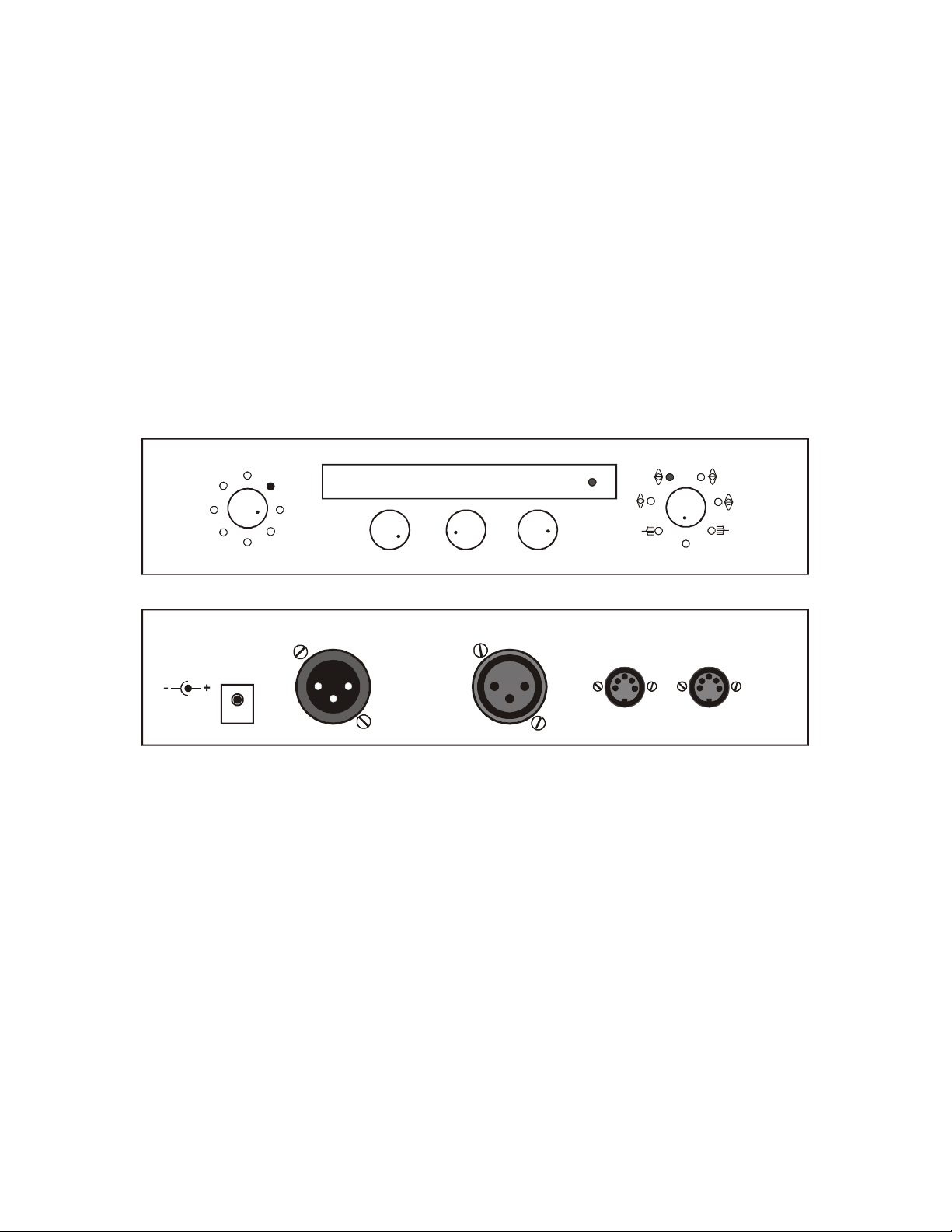
z-Qualizer
MIDI in
MIDI through
z-Qualizer Operations Manual
Welcome!
Congratulations on purchasing the z-Qualizer, the first low-cost outboard digital EQ
capable of world-class mastering performance. The z-Qualizer comes from a distinguished lineage of mastering processors that Z-Systems has been making for nearly
a decade. You’ve already heard our EQ algorithms on countless recordings and now
you have the chance to hear what they can do for your very own projects.
We urge you to read the following manual before using the z-Qualizer. We’re confident that anyone can learn to use it on their own, but it might be helpful to read the
manual and learn some of the finer points before diving in.
R
L
load
save
m-s & dither
ATTENTION/AVIS:
Risque de choc electronique.
Ne pas ouvrir.
To minimize risk of fire, use only the
specified power adapter.
9V DC
@500 mA
S
MIDI
byp
S -02.4 2k50 0. 8
gain
AES/EBU
Designed and manufactured in
the US by Z-Systems Audio
Engineering.
Do not open. Risk of electrical
shock. No user-serviceable
parts inside.
freq
outputinput
Q
signal
1
3
2
Z .
SYS
gain
Powering Up
Plug the DC power adapter that was included with the unit into an AC power outlet
and connect the other end of the DC power adapter to the DC power inlet on the back
of the unit. The z-Qualizer will power up quickly. Next, connect the z-Qualizer to an
AES/EBU standard digital audio source. The
signal LED will light to indicate the pres-
ence of a valid incoming signal.
Gain and Channel Offsets
We should mention a general rule at this point. The z-Qualizer is a stereo unit and it
can be operated in either dual-mono or stereo-linked modes. Dual-mono means that
the EQ parameters can be adjusted independently for the left and right channels. In
stereo-linked mode, the left- and right-channel EQ parameters track one another. The
L and R positions on the left knob are used to select between the left- and right-
1
Page 2

z-Qualizer manual Z-Systems Audio Engineering
channel parameter banks, whereas the S position puts the unit into stereo-linked
mode. The left-most edge of the alphanumeric display will always show whether the
unit is in
L, R, or S mode.
When the unit powers up, the left knob will be set to
knob will be set to
right knobs. In this mode, the only parameters showing in the alphanumeric display
will be an
knob indicating, in dBFS, the amount of gain (or attenuation) applied simultaneously
to the left and right channels:
S (indicating the z-Qualizer is stereo-linked) and a number above the gain
gain as indicated by the respective LEDs surrounding the left and
S, for “stereo” and the right
S +00.0
Turning the gain knob adjusts the stereo gain. To apply different gains to the left and
right channels, rotate the left knob to
numeric display changes to show an
mono mode, with the left-channel parameters currently active. Rotating the
changes the left channel gain. The procedure is similar for the right channel. If you
turn the left knob back to
The z-Qualizer is designed so that the left, right, and stereo gains can be different.
This allows you to dial in an offset between the left and right gains and then maintain
that offset by manipulating only the stereo gain.
The equalization in the z-Qualizer is performed with floating-point arithmetic and uses
very special proprietary low-distortion algorithms developed. There are six bands, including two first-order (6 dB per octave) shelves and four parametrics (bell curves).
S, you’ll see that the stereo gain is still the same as before.
L, for “left channel.” Observe that the alpha-
L indicating that the z-Qualizer is now in dual-
gain knob
Equalization
Stereo-linked mode:
Make sure the left knob is in the S position and turn the right knob to the low shelf
position (one click counter-clockwise from the gain position). The low shelf LED will
light and the alphanumeric display should look like:
S +00.0 1K00
Rotate the gain knob to change the gain of the low frequency shelving equalizer. Rotate the
place. This frequency is at the nominal 3 dB point of the curve. The first-order equalizer is extremely gentle and quite natural-sounding.
Dual-mono mode:
Rotate the left knob to put the z-Qualizer in left-channel mode. The alphanumeric
display now reads:
freq knob to change the frequency below which the shelving action takes
2
Page 3

z-Qualizer manual Z-Systems Audio Engineering
L +00.0 1K00
Here you can display and adjust the left channel shelf independently. Similarly, turn
the left knob to the
reo-linked mode, the
in
S mode. For example, if the L and R gains are different for the low shelving filter, if
you return to stereo-linked mode and adjust the gain, it gets copied to both the
R filters.
Important: You will notice that the “L” indicator in the display is blinking. This is to
remind you that the z-Qualizer is in dual-mono mode. The same is true for the “R”
when you are adjusting the right-channel parameters.
The other bands:
The high-shelf filter is accessed by turning the right knob one click clockwise from the
gain position, and performs exactly as above for stereo-linked or dual-mono equalization. The
freq knob controls the frequency above which action occurs.
R position and adjust the right channel. If you then return to ste-
L and R filters retain their settings until you change a parameter
L and
The four
Turn the right knob to any of these positions and you will see:
bell-shaped parametrics are numbered as 1, 2, 3, and 4 on the right knob.
S -00.0 1K00 0.4
This indicates, in order, stereo-linked or dual-mono mode, boost/cut, center frequency, and quality factor, or Q. As always, the label is above its corresponding knob,
and as above, turning the left knob to
channel separately. Q is the inverse of bandwidth. It is the product of center frequency divided by the 3 dB down bandwidth. Thus, a Q of 0.4 produces an extremely
wide curve and will be rarely used. A Q of 0.6 or 0.7 corresponds with the bandwidth
of a typical midrange EQ in an analog equalizer.
Dither
Turn the left knob to m-s & dither, The alphanumeric display will appear as follows:
L and R will allow you to control the left or right
M/S & Dither
24 un ENC:N DEC:N
As in all z-Qualizer menus, the labels appear above the knob which affects the parameter. For example, in this menu, you can change the wordlength and dither by rotating the left knob to any of the following:
3
Page 4

z-Qualizer manual Z-Systems Audio Engineering
24 un
24 di
20 un
20 di
16 un
16 di
16 p2
16 p3
The last two POW-r dither options are only available at 44.1 or 48 kHz. The sample
rate cannot be altered as the system is always slaved to the incoming rate.
Using the dither and wordlength settings
When the z-Qualizer equalizer is feeding additional digital processors, nearly always
set the output wordlength to 24 dith
AES/EBU and will send the highest resolution signal to the following device. The
dither in the z-Qualizer is a carefully-randomized floating point dither which removes
quantization distortion. The dither noise level at the 24 dith setting is at approximately -141 dB below full scale, so we doubt you will consider this to be an audible
problem! (To put this in perspective, most people consider analog tape hiss below
about -80 dB to be inaudible, and the noise floor of the best analog audio console in
the world is around -90 to -100 dB below full scale. Microphone preamplifiers can do
a bit better, but in the real world, noises add, and the practical full band noise of the
quietest typical musical recording is rarely better than about -70 dBFS, excluding
fadeouts).
. This is the maximum wordlength available in
However, the ear can easily hear signal as much as 20 dB or better below the wideband noise level, depending on the frequency and masking. That’s why we have to
use dither noise: to eliminate low level distortion caused by DSP processing. Without
dither noise, the sound of quantization distortion can reduce stereo imaging, and
make the sound cold and harsh, something to be avoided in most cases. The
ered
menu choices actually truncate the output of the z-Qualizer without concern for
quantization distortion.
The other dithered wordlength settings are only to be used if the z-Qualizer is con-
nected
use
pwr
CDR. A router may be used, but no additional DSP processor should be between the
Z Sys and the 16 or 20 bit device.
The only exception to the dither rule: you might choose to select the 24 undithered
option if you wish to bypass the z-Qualizer without turning the left knob to the byp position (in an automated session, for example, where one tune passes through flat
without any alteration). In this case, select
directly to a following device which truncates the wordlength. For example,
20 dith if the z-Qualizer is directly connected to a 20 bit ADAT. Use 16 dith or 16
if the z-Qualizer is connected directly to a 16-bit storage medium such as DAT or
24 un and make sure that all the gains
4
undith-
Page 5

z-Qualizer manual Z-Systems Audio Engineering
and equalizer levels are set to 00.0 dB. In the 24 un setting, with everything neutralized, the z-Qualizer is bit-transparent, (
without data alteration). In the
put to 20 bits (16 bits). These last two settings will rarely be used. Perhaps you wish
to cause some serious digital grittiness (assuming you are fond of the authentic
sound of early digital audio), or you need to truncate the signal because a preceding
device has not done so. Proceed with care when choosing any of the truncation settings; their use is extremely rare.
How to use the POW-r Dither
POW-r dither is a psychoacoustically-optimized dither. The two choices in the z-
Qualizer are
cording.
We can’t hear the effect of this shaping, but if you feel the shaping of
strong for you, then by all means choose
depth, space and resolution, but the loss is barely perceptible, and much smaller
than with competing noise-shaping processes.
POW-r 2 and POW-r 3, at 16 bits only, idealized for CD and DAT re-
POW-r 3 has the strongest noise-shaping, and yields the highest resolution.
20 un (16 un) setting, the z-Qualizer truncates its out-
i.e., it will pass all incoming AES/EBU signals
POW-r 3 is too
POW-r 2. POW-r 2 may yield slightly less
MS encode and decode
This versatile feature can be used in several ways. Let’s return again to the alpha-
numeric display:
24 un ENC:N DEC:N
The middle knob changes encode from no to yes, the right hand knob changes MS
decode from
gain, left and right channel adjustments and in front of the stereo equalizers. The MS
decoder is located after all processing and before the dither. In the z-Qualizer, the MS
encoder is at unity gain, and the decoder drops the gain by exactly 6 dB, which turns
out to be perfectly symmetrical---but you don’t need to know how the math works to
take advantage of
and gains are set to 0 dB, the system remains perfectly bit transparent, since its MS
encoder and decoder are exactly symmetrical, down to the last mathematical bit. You
can leave the system in
equalizer without any concern for losses.
MS stands for Mid-Side, or Mono-Stereo. When in MS Y, Y mode, internally the z-
Qualizer becomes an MS-style equalizer instead of a stereo equalizer. However, the
input remains stereo and the output remains stereo. It is useful to know that an MS
encoder contains the same circuit as a decoder. This means that you can use the encoder to decode and the decoder to encode if you wish. For example, you could feed
an MS signal into the z-Qualizer, decode it to stereo, manipulate the left and right
balance and eq, and then reencode it to MS for further processing in MS mode.
There are about 16 permutations you could think of, so the limit of flexibility is completely up to your imagination!
no to yes. The MS encoder in the z-Qualizer is located in front of the
MS mode. If the mode is set to ENC:Y DEC:Y and all equalization
ENC:Y DEC:Y mode if you wish and operate it as a stereo
5
Page 6

z-Qualizer manual Z-Systems Audio Engineering
Taking advantage of M/S
The most common use of MS equalization is to deal with center channel information
which needs separate EQ than the sides. If you feed a stereo recording into the zQualizer and set the mode to
gain
(or center gain), and the right channel gain control becomes the S gain (or side
gain). These controls can manipulate the width of the stereo image, while also reducing the ratio of the mix of center-located instruments to side-located instruments. Try
it. Feed in a good stereo recording with a center-located vocalist. Turn the
to gain and turn the left knob to L. Turn the gain knob counterclockwise until the L
gain is at -95 dB. The vocalist (and all center instruments) should virtually disappear,
and you will be left with a widely separated, out of phase mono representation of the
instruments and stereo vocal reverb. See what happens if you turn down the R gain
instead.
For equalization, you can cheat the frequencies for the M channel up or down separately from the S channel to manipulate the recording in creative ways. All the L labels are interpreted as M and the R labels as S. In
adjust full channel balance because the L and R gain controls have become M and S
controls, respectively.
MS Y, Y, the left channel gain control becomes the M
right knob
MS Y, Y mode there is no way to
The
presets (see below) remember the M/S state, so, for example, you can work on
one tune in MS mode and another in stereo mode.
Presets
Loading Presets
Rotate the left knob to the load position. The alphanumeric display will look some-
thing like this:
a=01 load
Rotate the gain knob (which is directly below the a=01 display) to choose the memory number from 00 to 99 from which to load, memory 00 is a factory default, which
is set to:
user-adjustable. To return the z-Qualizer to flat settings, simply use the following procedure with preset #00.
Let’s assume we want to load the contents of memory #34. Rotate the
til the alphanumeric display looks like this:
MS N, N; 24 bits; all gains and eqs at 0 dB. Memories 1 through 99 are
gain knob un-
a=34 load
6
Page 7

z-Qualizer manual Z-Systems Audio Engineering
Then rotate the Q knob (below the word load in the alphanumeric display). This loads
memory #34 and places an arrow next to the preset number to let you know the
memory has been loaded:
a=34< load
It’s that simple. If you change the preset number from the one that’s currently
loaded, the arrow disappears, indicating that you have to
new memory. Of course, the previously loaded memory is still in the equalizer until
the next
The
come back to that mode when you return to this screen.
Saving Presets
Rotate the left knob to the save position. The alphanumeric display will look some-
thing like this:
load. Try it. It’s easy and intuitive.
preset load function remembers the last memory you were working on, and it will
load again if you want this
a=01 save
You cannot save anything into preset 00. To save the current equalizer state into any
memory, rotate the gain knob to choose the memory, then rotate the Q knob (in either direction), and the display now looks like:
a=01< save
To save the current state of the equalizer into a series of memories, just increment
the memories with the left knob, rotate the right knob, and repeat. This is very useful
when you have been doing a job and want to neutralize a bunch of memories.
MIDI
Setting the MIDI channel
Connect the MIDI output to the input of a MIDI sequencer, and the MIDI input to the
output of the sequencer. Turn the
meric screen will look like this:
left knob to the MIDI position and the alphanu-
ID=02 read dump
To change the midi channel, rotate the gain knob. The channel is preserved in nonvolatile memory at power down.
7
Page 8

z-Qualizer manual Z-Systems Audio Engineering
SysEx Read
For a SysEx restore of all 99 presets from a MIDI sequencer, turn the freq knob (be-
low the word
read in the alphanumeric display) in either direction to prepare the zQualizer to receive SysEx data. Start your sequencer playing the sysex dump. While
the dump is proceeding, the word read will change to a numerical countdown from
99 to 1 to indicate the memories which are being restored. This takes only a few
seconds. When the SysEx restore is complete, the word
read re-appears in the alpha-
numeric display.
SysEx Dump
For a sysex dump of all 99 presets to a MIDI sequencer, first start your MIDI se-
quencer recording. Then rotate the
word
dump will blink and the sequencer should indicate that it is receiving MIDI data.
After all 99 memories have been sent to the sequencer, the display returns to
Q knob to start the dump. During the dump, the
dump.
MIDI Program Change
Connect the output of a MIDI sequencer to the MIDI in jack. Any time the z-Qualizer
sees a program change whose value is from 00 through 99, it will load the corresponding memory. In the
preset load mode the memory number will change to the
one sent by the MIDI program change command. Any other screen will display the
results of the program change.
Specifications
Input/Output: AES/EBU (transformer-isolated, 110-ohm terminated)
Input/Output precision: up to 24 bits
Gain control: from -95 dB to +12 dB
Gain resolution: 0.1 dB increments between 0 and 3 dB (gain or loss), 0.2
dB increments from 3 dB to 12 dB (gain or loss), 1 dB increments from –
12 dB to -20 dB, 2 dB increments from -20 to -50 dB, 3 dB increments
from -50 to -62 dB, 4 dB increments from -62 to -70, 5 dB increments
from -70 to-95 dB.
Filter types: 4 parametric, 2 shelving
Center frequency resolution: 1/6th octave ISO from 28 Hz to 20 kHz
Filter gain/cut: from -95 dB to + 12.0 dB with the same increments as the
gain control.
Filter bandwidths: Q=0.4, 0.5, 0.6, 0.7, 0.8, 0.9, 1.0, 1.1, 1.2, 1.3, 1.4,
1.5, 1.6, 1.7, 1.8, 1.9, 2.0, 2.5, 3.0, 4.0, 5.0, 6.0, 7.0, 8.0
Shelf filter slopes: 6 dB/octave (first order)
Channel separation: Effectively infinite
Dither types: 24 bit, 20 bit, and 16 bit proprietary floating-point tech-
niques, and 16 bit POW-r Dither (two types)
8
Page 9

z-Qualizer manual Z-Systems Audio Engineering
Digital filter architecture: proprietary minimum roundoff-noise structure
Dynamic range: better than 144 dB
Ergonomic Stereo-linked and dual-mono operation
Number of user-alterable presets: 99. Factory Preset: One (preset #00)
THD+N: better than -135 dB
Processor type: TMS320VC33 32-bit floating point DSP
Digital audio demodulator/modulator: Crystal Semiconductor
Sample rates supported: 32 kHz, 44.1 kHz, 48 kHz, 88.2 kHz, 96 kHz
Auxiliary-bit status handling: unit is transparent to channel status, validity,
and auxiliary bits
Power supply: 9 VDC @ 500 mA.
Z-Systems One-Year Warranty
All Z-Systems products come with an automatic one-year full warranty. We warrant to
the original purchaser that the product purchased will be free of defects for a period
of one year from the date of purchase. Z-Systems will, without charge, replace or repair, at its option, defective products or component parts upon delivery to the manufacturer. This warranty does not apply in the event of misuse or abuse as a result of
unauthorized alterations or repairs. For warranty service work, simply contact the
manufacturer to arrange for return and repair. Z-Systems will not be liable for any
consequential damages, including, without limitation, damages resulting from loss of
use.
An Invitation to You
After you have used your Z-Systems product for a while, call, fax or email us and tell
us what you think. We enjoy hearing from you. Many of our new products, updates
and modifications were designed as solutions to technical problems encountered by
our end-users. Our enthusiastic customers help spread the good word about ZSystems. We would like you to be one of them.
Z-Systems Audio Engineering
1325 NW 53
rd
Ave Suite B
Gainesville, FL 32653 USA
(352) 371-0990 (voice)
(352) 371-0093 (fax)
z-sys@z-sys.com
9
 Loading...