

Page 1

z-CL6 manual © 2000, Z-Systems Audio Engineering
The z-CL6 Six-Channel
Mastering Dynamics Processor
Controlling Attack and Release Times.................................................................................................................. 3
Controlling Threshold and Compression Ratio................................................................................................... 4
Controlling Hipass Filters and Make-up Gain.....................................................................................................4
Saving and Loading Presets................................................................................................ ...................................5
MIDI Automation.................................................................................................................................................. 6
Adjusting Wordwidth............................................................................................................................................7
Controlling Compressor Linking..........................................................................................................................8
Specifications........................................................................................................................................................ 11
Figure 1 - z-CL6 front panel controls...................................................................................................................2
Figure 2 - attack/release screen.............................................................................................................................. 3
Figure 3 - threshold/ratio screen...........................................................................................................................4
Figure 4 - hipass/make-up gain screen.................................................................................................................4
Figure 5 - preset mode........................................................................................................................................... 5
Figure 6 - confirmation of preset save..................................................................................................................6
Figure 7 - indication that preset has not been saved............................................................................................6
Figure 8 – MIDI control screen.............................................................................................................................7
Figure 9 - wordwidth/sample rate mode..............................................................................................................7
Figure 10 - compressor linking screen..................................................................................................................8
Figure 11 - z-CL6 block schematic...................................................................................................................... 10
Page 2

z-CL6 manual
2
(K) presets/wordwidth screen select button
(J) hipass/make-up gain screen select button
(C) parameter #1 display (E) parameter #2 display
(A) channel indicator
(G) threshold/ratio screen select button
(H) cross-linking screen select button
(I) attack/release screen select button
LRF:
thr -12.0
LRS:
thr -11.0
CEN:
thr -11.0
SUB:
thr -12.0
(L) channel bypass buttons
(B) channel select knob
(D) parameter #1 control knob
rat 1.4:1
rat 1.1:1
rat 3.0:1
rat LIMIT
-8 0
-8
-8
-8
(F) parameter #2 control knob
0
(M) gain reduction meter
0
0
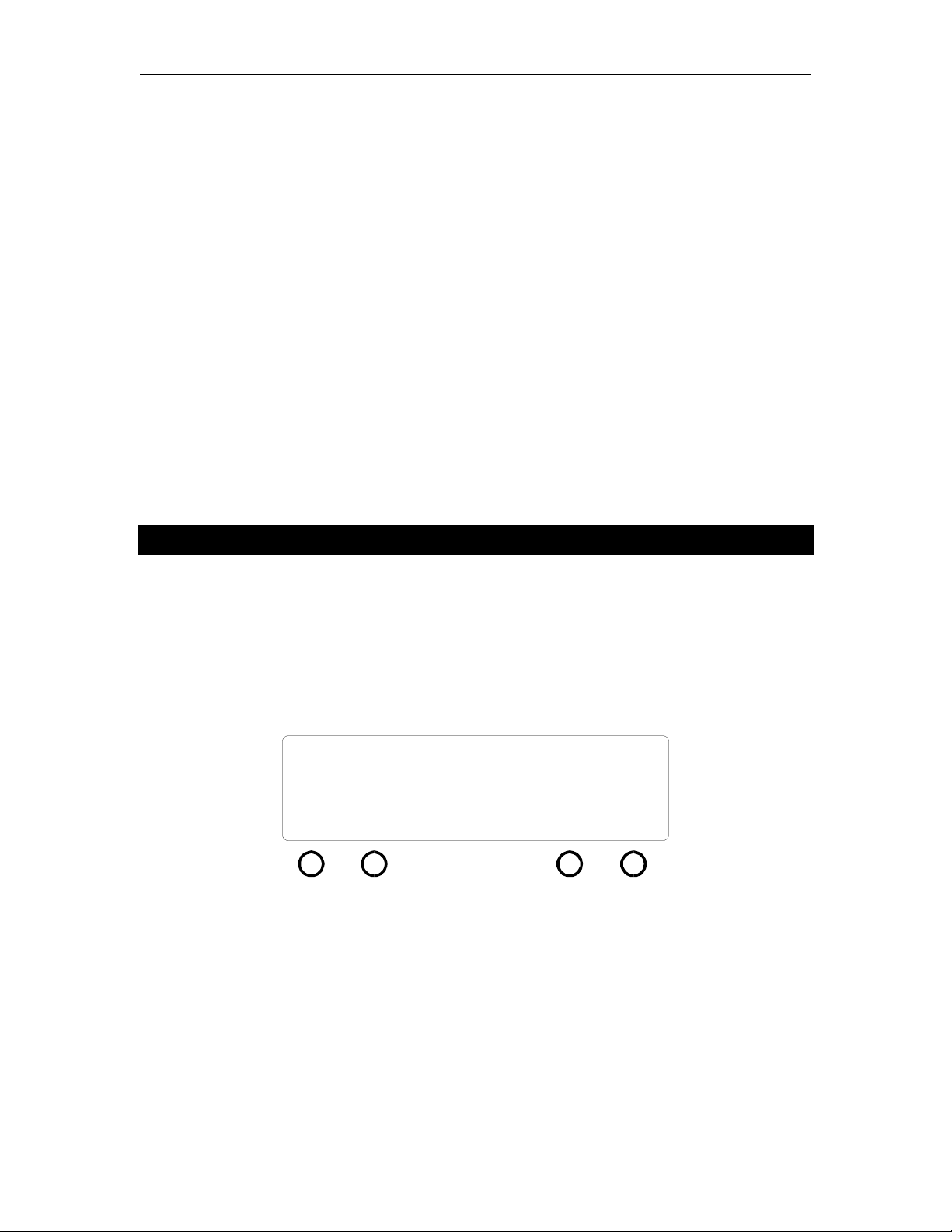
Figure 1 - z-CL6 front panel controls
Using the z-CL6 is very simple once you understand its display and control methodology.
Because there are so many channels and so many parameters for each channel, only a few things
can be displayed at a time. We have chosen to display the same parameters for all channels rather
than all of the parameters for a selected channel; this is the basis for our display/control model.
To begin, the z-CL6 partitions the channels into four groups:
• LRF – left and right front channels
• LRS – left and right surround channels
• CEN – the center channel
• SUB – the subwoofer channel
Referring to Figure 1, there are four parameter control screens, each selected by one of the screenselect buttons (G, H, I, and J). These screen-select buttons each invoke a different mode in which
the parameters associated with that mode can be controlled by the parameter #1 and parameter #2
control knobs (D and F). These four modes are:
• Attack/release mode (invoked by button I)
• Threshold/ratio mode (invoked by button G)
• Hipass/make-up gain mode (invoked by button J)
• Compressor cross-linking mode (invoked by button H)
The parameters associated with these modes are displayed in the parameter #1 display (C) and the
parameter #2 display (E). Within any of the modes, use the channel select knob (B) to choose
which channel group is affected by the parameter control knobs. As you turn the channel select
knob, the channel indicator (A) will point to the corresponding channel.
There is a gain reduction meter (M) which is visible from any of the four mode screens. The gain
reduction meter gives a simultaneous visual display of the amount of gain reduction being
performed on all four of the channel groups. The meter continues to function while you are
changing the values of the parameters, which gives useful visual feedback about your parameter
choices.
Page 3

z-CL6 manual
3
Each of the channel groups is endowed with a channel bypass button (L). When this button is
pressed, the corresponding compressor is disengaged and there is a direct signal path from input
to output for that channel group; output is bit-for-bit identical to output. When the bypass
button is pushed, the gain-reduction meter for that particular channel vanishes and is replaced
with a bypass indicator. While a channel is bypassed, its parameters can still be adjusted. These
new parameters will be in effect when the channel is taken out of bypass.
Finally, there is a button (K) for invoking a system mode where you can control the wordwidths
of the different channel groups and you can save and load presets.
Controlling Attack and Release Times
LRF:
LRS:
CEN:
SUB:
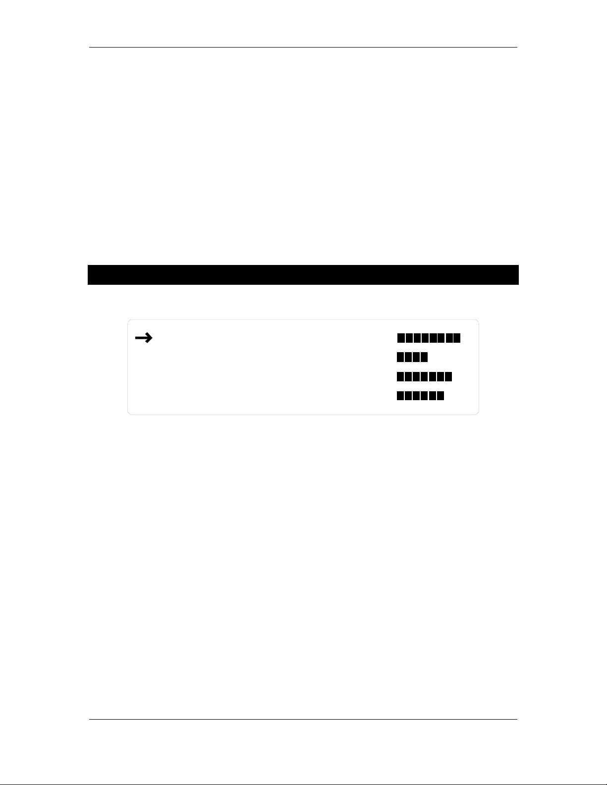
Press the attack/release screen select button. The display will appear as in Figure 2. Use the
channel select knob to move the arrow to the desired channel. The parameter #1 knob controls
the attack time and the parameter #2 knob controls the release time. Both the attack time and
the release time are calibrated in milliseconds. The gain reduction meters will continue to
function when the z-CL6 is in attack/release mode, as will the individual channel bypass buttons.
Attack times range from instant to 950 milliseconds. Release times range from instant to 950
milliseconds. A typical rule of thumb is to set the release time to ten times the attack time. Notice
that the z-CL6 has more attack time choices than release time choices, with a higher density of
values below 10 milliseconds.
att 0.05
att 0.10
att 10.0
att 100
Figure 2 - attack/release screen
rel 5.0
rel 10.0
rel 50.0
rel 100
-8 0
-8
-8
-8
0
0
0
Page 4

z-CL6 manual
4
Controlling Threshold and Compression Ratio
LRF:
LRS:
CEN:
SUB:
Press the threshold/ratio screen select button. The display will appear as in Figure 3. Use the
channel select knob to move the arrow to the desired channel. The parameter #1 knob controls
the threshold and the parameter #2 knob controls the compression ratio. The threshold is
calibrated in decibels relative to full-scale digital (dBFS) and the compression ratio is to be
determined as the number of decibels the input level must rise above the threshold in order to
produce a one-decibel increase in output level. The gain reduction meters will continue to
function when the z-CL6 is in threshold/ratio mode, as will the individual channel bypass buttons.
The threshold ranges from 0.0 dB to -95 dB. The ratio can be made to vary from 1.1:1 to 8.0:1.
Turning the ratio knob one click past 8.0:1 turns the compressor for that particular channel into a
limiter, with a ratio of 100:1.
thr -12.0
thr -18.0
thr -14.0
thr -12.0
Figure 3 - threshold/ratio screen
rat LIMIT
rat 1.1:1
rat 3.0:1
rat 2.0:1
-8 0
-8
-8
-8
0
0
0
Controlling Hipass Filters and Make-up Gain
LRF:
LRS:
CEN:
SUB:
Press the hipass/make-up button. The display will appear as in Figure 4. Use the channel select
knob to move the arrow to the desired channel. The parameter #1 knob controls the corner
frequency of the hipass filter (explained below) and the parameter #2 knob controls the
compressor make-up gain. The make-up gain is calibrated in decibels relative to full-scale digital
(dBFS). The gain reduction meters will continue to function when the z-CL6 is in hipass/makeup gain threshold/ratio mode, as will the individual channel bypass buttons.
hp 100 Hz
hp 100 Hz
hp 100 Hz
hp 10 Hz
Figure 4 - hipass/make-up gain screen
mkg +1.00
mkg +0.00
mkg +0.60
mkg +0.00
-8 0
-8
-8
-8
0
0
0
Page 5
z-CL6 manual
5
The purpose and function of the hipass filters require a bit of explanation. In essence, a
compressor consists of two blocks: a level detection block and a gain control block. The level
detection block senses the level of the input signal and compares it to the user-determined
threshold. When the input level exceeds the threshold, the detection block tells the gain control
block to decrease the output level by the amount specified by the compression ratio. We have
provided a hipass filter that goes before the level control block. This allows you to remove a
desired amount of the low-frequency energy from the input signal so that the low frequencies
don’t trigger the compressor. This may prove to be useful for previewing different bass
management modes for Dolby and DTS surround mastering.
The corner frequency parameter specifies the – 3 dB point for the hipass filter. Below the corner
frequency, the filter has a slope of 12 dB per octave. The corner frequency can be varied from 10
Hz to 990 Hz. The 10 Hz setting is useful simply for blocking DC level from the level detector.
Do not be alarmed by the presence of these hipass filters; remember – they are not in the audio
path, but rather in the level detection path.
The make-up gain function serves two purposes. The first is to allow you to increase the overall
signal level, post-compression. The second is as a digital volume control for controlling relative
levels between the various surround groups. The make-up gain has a range from –95 dB to +12
dB referenced relative to full-scale digital (dBFS).
Saving and Loading Presets
The entire state of the z-CL6 can be saved and recalled. Press the presets button once. This will
bring the z-CL6 to the state shown in Figure 8. To save a preset, use the middle knob (as
prompted by the display) to choose a preset number then press the button beneath the SAVE
indication. This will then bring the z-CL6 to the state shown in Figure 9, which confirms that the
SAVE operation took place.
(L knob) (R knob)
preset #21
LOAD
SAVE READDUMP
Figure 5 - preset mode
MIDI #12
Page 6

z-CL6 manual
6
(L knob) (R knob)
preset #21 saved
MIDI #12
LOAD
SAVE READDUMP
Figure 6 - confirmation of preset save
There is one special preset that can not be over-written. This preset is given number 00 and stores
the z-CL6 's "flat" settings. This is the preset you will want to use in order to return the z-CL6 to a
"blank" setting. If you attempt to over-write preset 00, the display will appear as in Figure 7,
which tells you that the preset was not saved and that you should choose another preset number.
(L knob) (R knob)
preset #00 not saved
LOAD
Figure 7 - indication that preset has not been saved
SAVE READDUMP
MIDI #12
To recall a preset, from the screen in Figure 5 press the button beneath the LOAD indication. The
preset indicated in the display will be loaded and the z-CL6 will jump to the mode from which the
preset mode was invoked.
MIDI Automation
The z-CL6 can be automated via MIDI commands; it supports MIDI program change commands
and also uses system exclusive commands to allow the unit’s entire collection of presets to be sent
to and restored from a MIDI sequencer.
The z-CL6’s MIDI controls are on the same screen as the preset LOAD and SAVE screen. Simply
press the presets button once, which brings the z-CL6 to the state shown in Figure 8.
(L knob) (R knob)
preset #21
LOAD
SAVE READDUMP
MIDI #12
Page 7

z-CL6 manual
7
Figure 8 – MIDI control screen
To set a MIDI channel number, use the right knob, as prompted by the screen. This sets the
MIDI channel the z-CL6 will use for both its MIDI program change commands and for system
exclusive messages.
To save all 50 of the z-CL6’s presets, put your MIDI sequencer into record mode with the channel
set to the z-CL6’s MIDI channel. Press the button below the DUMP message on the screen. You
will see the preset counter on the left part of the z-CL6’s screen count backwards from 50 down to
01. This lets you know that the z-CL6 is sending its entire bank of presets, one at a time, to the
MIDI sequencer via MIDI system exclusive commands. When the system exclusive dump is
finished, the z-CL6 will return to the preset number that was displayed before the DUMP
command was executed.
To retrieve a collection of 50 presets from a MIDI sequencer, again make sure you have the zCL6’s MIDI channel number set to the same channel as the MIDI sequencer. Press the button
below the READ message and then begin to play the MIDI system exclusive stream from your
MIDI sequencer. The preset counter will again count backwards, letting you know that the z-CL6
is indeed receiving and decoding the system exclusive commands. When the z-CL6 has decoded
the last preset from the MIDI sequencer, it will jump to normal operating mode and will be ready
for either normal user input via the knobs and buttons or for MIDI program change commands.
To execute MIDI program change commands, simply make sure the MIDI sequencer is set to the
same MIDI channel as the z-CL6 and begin sending program change commands. The z-CL6 will
jump to the preset number indicated by the program change, with the display updated to show
the parameter changes. If an invalid program number is sent to the z-CL6, it will be ignored.
Adjusting Wordwidth
(M knob)
24dith
LRF
16bits24dith
*LRS
Figure 9 - wordwidth/sample rate mode
CEN
24dith
SUB
From the preset mode, press the preset/dither button to get to the wordwidth mode. The display
will appear as in Figure 9. As prompted by the display, the wordwidths are controlled by the
middle knob. Use the button below the indicated channel group names to select the group of
interest, and an asterisk will appear to indicate the selection, as in Figure 9.
Page 8
z-CL6 manual
8
The wordwidth for each channel group can be controlled independently. There are six settings for
each wordwidth:
24 bits dithered
24 bits undithered
20 bits dithered
20 bits undithered
16 bits dithered
16 bits undithered
16 bits POW-r #2
16 bits POW-r #3
The dither used is a variant of flat TPDF dither, while POW-r #2 and #3 are noise shaping curves.
Press any of the other mode select buttons to exit from the wordwidth rate mode.
Controlling Compressor Linking
LRF:
LRS:
CEN:
SUB:
One of the z-CL6's most powerful features is its ability to link the level detection and compression
action across multiple channels. At first, it may seem slightly awkward to control the linking but
we are confident you will quickly find the controls to be intuitive and easy to use.
There are four channel groups on the z-CL6: the fronts, the surrounds, the center, and the
subwoofer. Each of these groups is endowed with two controls: a mix control and an out control.
The purpose of these controls is to allow you to vary the amount of interaction each of the
channel groups has with the other groups.
Internally, the z-CL6 generates four "sums of levels" They are:
Sum
= outlevel(LRS) + outlevel(CEN) + outlevel(SUB)
LRF
Sum
= outlevel(LRF) + outlevel(CEN) + outlevel(SUB)
LRS
Sum
Sum
= outlevel(LRF) + outlevel(LRS) + outlevel(SUB)
CEN
= outlevel(LRF) + outlevel(LRS) + outlevel(CEN)
SUB
mix 50%
mix 100%
mix 50%
mix 100%
Figure 10 - compressor linking screen
out 0%
out 50%
out 100%
out 0%
-8 0
-8
-8
-8
0
0
0
Notice that each of these sums is simply the sums of three of the four group levels with one of the
groups omitted.
The value of "outlevel" for a channel group is nothing more than the group's actual level
multiplied by the percentage indicated by the out parameter for that group.
Page 9

z-CL6 manual
9
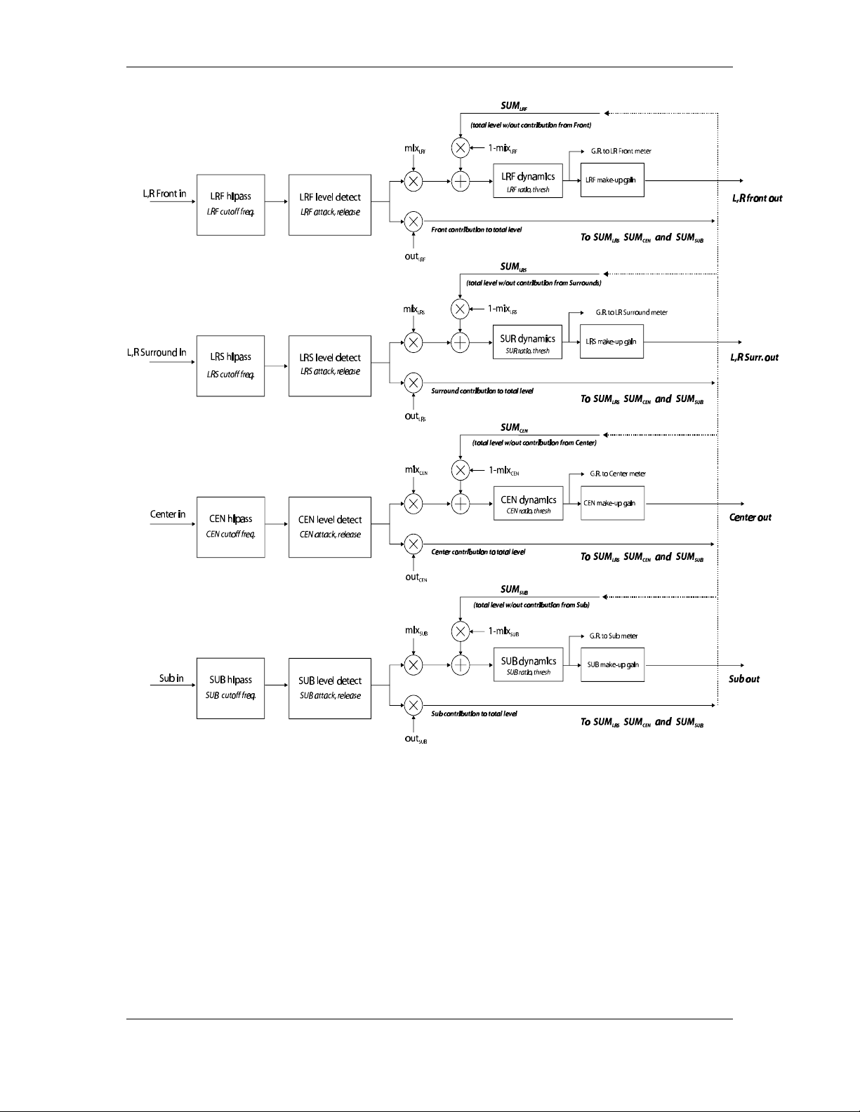
Next, the mix parameter controls how much of the Sum in question gets added in to the
compressor's level detector along with the level from that channel group. For example, the mix
parameter for the LRF channel group determines what percentage of Sum
gets added into the
LRF
LRF group's level detector along with the level contributed by the LRF group itself. A value of
100% for the mix parameter means that the compressor sees all (100%) of the level from its own
channel group and 0% of the Sum level. A mix parameter of 75% means that the compressor sees
75% of the level from its own channel group and 25% of the Sum level. This is shown
schematically in Figure 11.
As shown in Figure 9, the LRF group contributes nothing to any of the Sums, the LRS group's
level is weighted by 50%, the center level is weighted by 100%, and the subwoofer level
contributes nothing to the Sums. Then, the front group compressor uses a mixture of 50% of the
LRF level and 50% of Sum
(which is equal to 50% of the LRS level plus 100% of the center
LRF
level).
The subwoofer compressor gets 100% of its level from the subwoofer level and nothing from the
other channels.
Page 10
z-CL6 manual
10
Figure 11 - z-CL6 block schematic
Page 11

z-CL6 manual
11
Specifications
• Inputs and outputs: Transformer-isolated, 110-• terminated AES/EBU (3 inputs, 3 outputs)
• Sample rates supported: 32 kHz – 96 kHz
• Input resolution: up to 24 bits
• Output resolution: 16, 20, or 24 bits undithered or TPDF dithered
• Compression ratios: 1.1:1 to 8.0:1
• Limiter ratio: 100:1
• Threshold: from –95.0 dBFS to 0.00 dBFS
• Attack time: from 5.0 •s to 950 ms.
• Release time: from 5.0 •s to 950 ms.
• Highpass filters in detector chains: -12 dB/octave slope w/corner frequency from 10 Hz to 990
Hz
• Dynamic range: better than 130 dB
• THD + Noise: less than –130 dB
• AC Power: 110/220 volts @ 50/60 Hz
 Loading...