

Page 1
Digital Detangler Pro Manual Z-Systems Audio Engineering
FUSE
from 1-8 from 9-16from 17-24 from 25-32
FUSE
from 1-8 from 9-16 from 17-24 from 25-32
Digital Detangler Pro Instructions
The Digital Detangler Pro is an automated patchbay/distribution-amplifier for digital audio
signals. The primary function of the Digital Detangler Pro is to route the outputs of different
machines to the inputs of other machines. For example, the output of a digital audio workstation
(DAW) may be sent to the inputs of 16 DAT machines simultaneously. Or, the output of one DAW
may be sent to 8 DAT machines while the output of another DAW is sent to another 5 DAT
machines and the output of an A/D converter is sent to still another 3 machines. The power of the
Digital Detangler Pro is that the various devices are physically connected to the Digital Detangler
Pro in one configuration, while the output-to-input routing patterns can be changed dynamically
without needing to unplug and rearrange cables.
The terminology used throughout this manual is simple. Device outputs are sent to the
Digital Detangler Pro’s inputs. These signals are referenced by the term "from." The Digital
Detangler Pro’s outputs are sent to device inputs. These signals are reference by the term "to."
For example, we route "from" a CD player "to" a DAT machine.
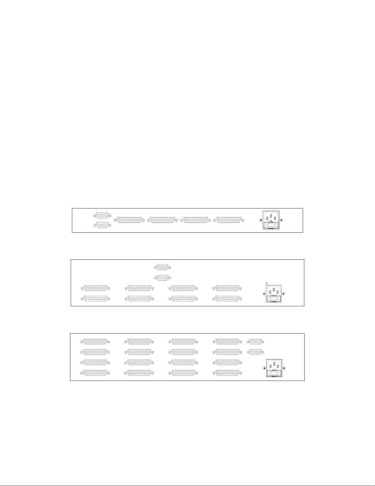
Figure 1 shows the rear panel layouts of the various Digital Detangler Pro models.
Observe that the Digital Detangler Pro uses DB25 connectors for its digital audio inputs and
outputs. The pinout is the same one that the Tascam DA88 uses for its analog I/O, only you will
want to use digital cable. We can provide you with these cables or we can refer you to various
other vendors.
caution: pin 1 = +5VDC
RS422 in
RS422 thru
z-systems audio engineering, gainesville, fl, usa
to 1-8 to 9-16 from 1-8 from 9-16
z-systems audio engineering, gainesville, fl, usa
z-16.16r and z-8.8r rear panel (above)
caution: pin 1 = +5VDC
RS422 in
RS422 thru
110/220 VAC
voltage selection
inside
FUSE
110/220 VAC
voltage selection
110/220 VAC
voltage selection
inside
inside
to 1-8 to 17-24 to 25-32to 9-16
z-32.32r rear panel (above)
z-systems audio engineering, gainesville, fl, usa
to 9-16
to 1-8 to 33-40
from 33-40 from 41-48 from 49-56 from 57-64
to 25-32
to 17-24
z-64.64r rear panel (above)
to 41-48
1
to 57-64
to 49-56
caution: pin 1 = +5VDC
RS422 in
RS422 thru
110/220 VAC
voltage selection
inside
Page 2
Digital Detangler Pro Manual Z-Systems Audio Engineering
1
1G1+2-3G3+4-5G5+6-7G7+
8-
RS422 in
RS422 thru
FUSE
110/220 VAC
voltage selection
inside
z-128.128r rear panel (above)
Figure 1: Digital Detangler Pro rear panel layouts
An important note: Digidesign uses a DB25-to-XLR harness for AES/EBU I/O on their new ProTools
HD system, but the pinout is different. They put four AES/EBU sources and four AES/EBU
destinations on a single DB25-to-XLR cable. We put either eight AES/EBU sources or eight AES/EBU
destinations on a single DB25-to-XLR cable. We can supply you with ProTools HD-to-Digital
Detangler Pro adapter harnesses.
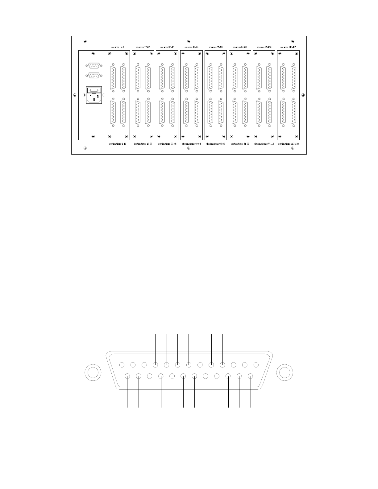
Also note that the naming convention in Figure 2 is based on stereo pairs. For example, pins 1G, 1+,
and 1- would connect to the three pins of an XLR connector for AES/EBU, and this connector carries
two channels of digital audio. Thus, a single DB25 connector carries eight stereo pairs of digital
audio.
Furthermore, the naming of the various models references how many stereo pairs of digital audio
are supported. For example, the z-32.32r has 32 stereo pairs in and 32 stereo pairs out. The units
can not cross-route different halves of a stereo pair; all routing must be done on a stereo-pair basis.
You will want female XLRs on the source harnesses and male XLRs on the destination
harnesses. If in doubt, or if you wish to make your own cable assemblies, Figure 2 shows the
proper pin-out for both the source and destination connectors.
1- 2G 2+ 3- 4G 4+ 5- 6G 6+ 7- 8G 8+
6
7
8
9
10
11
12
13
18
19
20
21
22
23
24
25
Figure 2 – DB25 pinout
The configuration of the Digital Detangler Pro is defined by a set of "to/from" pairs. Each
"to" can have only one "from" sent to it at a time (to do otherwise would require a digital mixer).
2
2
3
4
5
15
16
17
14
Page 3

Digital Detangler Pro Manual Z-Systems Audio Engineering
Changing the configuration of the Digital Detangler Pro is simple -- you merely edit the to/from
pairs one at a time until you have the desired configuration. If you have a number of different
configurations you will be using frequently (e.g., CD mastering setup, DAW archive-to-tape setup,
DAW load from multitrack setup, DAT duplication setup, etc.), you have the ability to reconfigure
the Digital Detangler Pro for your needs at the touch of a few buttons -- the remote controller for
the Digital Detangler Pro allows you to save and recall up to 15 entire configurations. These
configurations are held in non-volatile memory in the remote controller. This means that the
configurations are held between power-downs.
The Digital Detangler Pro itself also has non-volatile memory, but only for one
configuration. The remote control can be used to edit this configuration and put it in the Digital
Detangler Pro memory. Then, whenever the Digital Detangler Pro is powered up this configuration
will be loaded, regardless of whether or not the remote control is attached.
Figure 3 shows the front-panel layout for the z-rrc router remote control unit. The
controls/indicators have the following functions.
Figure 3 – Router Remote Control
•• to/save display. This indicator shows the "to" half of the to/from pair being edited. When
saving configurations, this indicator shows the memory location to be used to save the
configuration.
•• from/load display. This indicator shows the "from" half of the to/from pair being edited.
When loading configurations, this indicator shows the memory location from which to load.
•• left knob. This knob is used to scroll through the "to" device numbers. Turning the left
knob clockwise increments the "to" device number, while turning it counter-clockwise decrements
the "to" device number. As the "to" number is changed, the "from" number changes with it,
showing the current state of the to/from pair.
3
Page 4

Digital Detangler Pro Manual Z-Systems Audio Engineering
When loading or saving configurations, the left knob is used to scroll through the "save" or
“load” memory locations.
•• right knob. This knob is used to scroll through the "from" device numbers. Turning the
right knob clockwise increments the "from" device number, while turning it counter-clockwise
decrements the "from" device number. The "to" device number does not change, so turning the
right knob changes the "from" half of the to/from pair.
•• save button. Pressing this button puts the remote controller into save mode. When the
save button is pressed, the save indicator turns on, the from/load display goes blank, and the
to/save display indicates the save number. The left knob is used to select the save number.
Pressing the cancel button aborts this operation, while pressing the save button a second time
saves the configuration and returns the remote controller to normal mode.
•• load button. Pressing this button puts the remote controller into load mode. When the
load button is pressed, the load indicator turns on, the to/save display goes blank, and the
from/load display indicates the load number. The left knob is used to select the load number.
Pressing the cancel button aborts this operation, while pressing the load button a second time
loads the configuration and returns the remote controller to normal mode.
•• route button. Pressing this button sends the current configuration of the remote
controller to the Digital Detangler Pro and establishes the connection pattern in the router. Until
the route button is pressed, the configuration is local to the remote controller only -- the Digital
Detangler Pro will not change its configuration until this button is pressed. This allows you to make
configuration changes and not have them take effect until they are complete.
•• save indicator. This LED indicates that the remote controller is in save mode.
•• load indicator. This LED indicates that the remote controller is in load mode.
•• router # indicators. These LEDs indicate which router is being controlled by the remote
controller. To change the router number, press the load button and the save button at the same
time. Both the save indicator and the load indicator will light and both the to/save display and
the from/load display will go blank. Now, the left knob is used to change the router number,
which will be reflected by the router # indicators. The exit button is used to return to normal
operation.
•• escape button. This button is used to cancel load and save operations and to return to
normal operation from the router number change sequence.
When the power is first turned on, the Digital Detangler Pro wakes up with its own
configuration (the one stored in its own non-volatile memory) while the remote controller wakes up
in the configuration stored in memory location #1. Obviously, the Digital Detangler Pro and the
remote might not have the same configurations. Therefore, it is important to be able to determine
what configuration the Digital Detangler Pro is holding. To do this, simply load from memory
location #16 (in other words, hit the load button, turn the right knob until 16 shows on the
from/load display, and hit the load button again). The remote controller will now hold the same
configuration as the Digital Detangler Pro.
Although the remote controller will let you save the configuration to memory location #16,
don't do it since it will not be possible recall this configuration.
Figure 4 shows the RS422 input DB9 receptacle on the back of the Digital Detangler Pro. This is
the receptacle to which you should connect the router remote controller. Be careful if you are
using the Macintosh software interface for the Digital Detangler Pro -- please use the cable we
supply in order to connect your computer and the router. It is important to make note that pin 1
4
Page 5

Digital Detangler Pro Manual Z-Systems Audio Engineering
1
1
6
6
2
2
7
7
3
3
8
8
4
4
9
9
5
5
RX-
TX-
RX+
GND
TX+
RS422 IN
RS422 THRU
on the connector is a +5-volt power supply pin, used to supply power to the remote
controller. If the Digital Detangler Pro is to be hooked up to a computer, it is critical that
this pin not be passed through to the computer's serial port. The +5-volt power output is not
present on the RS422 thru receptacle. To daisy-chain multiple routers, simply attach the remote
controller to the RS422 input receptacle of the first router, connect the RS422 thru receptacle of
the first router to the RS422 in receptacle of the second router, and so forth.
A note about computer control for the Digital Detangler Pro:
Z-Systems can supply you with computer interface kits for the Digital Detangler Pro. Both
Windows and Macintosh software are available. The Windows control kit consists of
software for the PC, an RS232-to-RS422 converter module, and a special cable. The
Macintosh control kit consists of software for the Mac OS and a special Mac mini-DIN-toDB9 converter cable. Contact your dealer or Z-Systems for information and pricing on the
software control kits. If you wish to write your own software, please send an email to
info@z-sys.com asking for a copy of the control protocol.
RX+
GND
TX+
5V
RX-
TX-
Figure 4 – RS422 in and RS422 thru port pinouts
5
 Loading...