

ZPA Pecky, a.s. MODACT MO EE 52 120, MODACT MO EE 52 124, MODACT MO EE 52 121, MODACT MO EE 52 123, MODACT MO EE 52 125 Mounting And Operating Instructions
...
Electric rotary multi-turn actuators
MOUNTING AND OPERATING
INSTRUCTIONS
Explosion-proof design
Type numbers 52 120 - 51 125
10/18

ZPA Pečky, a.s. is certified company in accordance with ISO 90001 as amended.

CONTENS
1. Application .................................................................................................................... 3
2. Operating conditions; Operating position ..............................................................................6
3. Operation mode; Service life of actuators ..............................................................................7
4. Technical data ................................................................................................................ 8
5. Actuator outfit ................................................................................................................9
6. Elektrical parameters ...................................................................................................... 10
7. Description .................................................................................................................. 12
8. Packing and storing ....................................................................................................... 20
9. Assembling and putting the electric actuator into operation ..................................................... 20
10. Adjustment of electric actuator with valve ........................................................................... 21
11. Operation and maintenance ............................................................................................. 22
12. Failures and their removal ............................................................................................... 23
Tables ..........................................................................................................................24–25
Dimensions of the actuators MODACT MO EEx .......................................................................26–31
Diagram of electric wiring ..................................................................................................32–38
List of spare parts ................................................................................................................ 39
The Mounting and Operating Instructions specify basic principles for mounting, connection, adjustment, operation,
maintenance, and repairs of electric explosion-proof actuators. A fundamental prerequisite is that assembly, operation,
maintenance, and revisions are performed by skilled technicians qualified for operation and works on explosion-proof
electric devices and the works are supervised by a professionally qualified expert instructed in a demonstrable way.
1. APPLICATION
The MODACT MO EEx electric rotary multi-turn actuators are specially intended for controlling devices by a reversing
rotary motion, e.g. slide valves and valves, and, in connection with an appropriate gearbox, also flap or ball valves,
and other devices for which they are suitable due to their properties.
They can be operated in an environment with a danger of explosion of explosive gaseous atmosphere in zone 1 and zone
2 according to ČSN EN 60079-10-1. The actuators are designed as a device of group II, category 2G in compliance with
standards ČSN EN 60 079-0:2013, ČSN EN 60 079-1:2015 and ČSN EN 60079-7:2017 for explosive gaseous atmosphere.
The actuators MODACT MO EEx are available for surrounding temperature from -25 °C to +55 °C.
The actuators MODACT MO EEx are available for surrounding temperature from -50 °C to +55 °C (in the version
without position transmitter or with current transmitter CPT 1AF). In the type designation, there are letters F
(52 12x.xxxxF) at the last places of their complementary type number.
The actuators marked
The actuators are marked with protection against explosion and symbols of the group and category of the device
II 2G and according to version for surrounding temperature from -25 °C to +55 °C with marking Ex db eb IIC T4 Gb
(type No. 52 125 with marking Ex de IIB T4 Gb) or for surrounding temperature from -50 °C to +55 °C or -60 °C to +55 °C
with marking Ex db eb IIB T4 Gb (see Data on actuators).
The actuators
Electric actuators MODACT MO EEx can be supplied in mining version marked I M2 Ex db eb I Mb.
Another modification of actuators is design for use in spark-safe control circuits. Certification of MO EEx actuators was
extended and the actuators defined as simple device according to Art. 5.7 ČSN EN 60079-11 with marking “II M2 Ex db ib I Mb”.
With their design, the actuators meet basic conditions of the level of spark safety protection “ib”. The control part of the
circuits (control of actuators) and the power part of the circuits (electric motors) are separated and each has its own switchboard.
MODACT MO EEx of mining version
The actuators marked
– label of protection against explosion and symbols of the group and category of the device II 2G or I M2
– and according to version for surrounding temperature
from -25 °C to +55 °C with marking Ex db eb IIC T4 Gb
(type No. 52125 marked Ex db eb IIB T4 Gb)
from -50 °C to +55 °C or from -60 °C to +55 °C with marking Ex db eb IIB T4 Gb
3

– as modification for use
in mines in group I, category M2 with marking Ex db eb I Mb
– as modification for use in spark-safe control
circuits in mines group I, category M2 with marking Ex db ib I Mb
Designation of explosion-proof properties
It consists of the following symbols:
Ex Electric device complies with the standard ČSN EN 60 079-0 and related standards for various types of protection
against explosion.
db
Designation of the type and level of protection against explosion, explosion-proof closure according to ČSN EN 60 079-1.
eb Designation of the type and level of protection against explosion, secured version according to ČSN EN 60 079-7.
II Designation of the group of explosion-proof electric device according to ČSN EN 60 079-0.
B, C Designation of the sub-group of the group of explosion-proof electric device according to ČSN EN 60 079-0.
T4 Designation of temperature class of explosion-proof electric device of the Group II according to ČSN EN 60 079-0.
Gb Designation of an explosion-proof electric device for explosive gas atmospheres with a “high” level of protection and
is not a source of ignition in normal operation or during expected malfunctions, according to ČSN EN 60079-0.
ib Designation of protection of spark safety according to ČSN EN 60 079-11.
Nomenclature
Environment with explosion danger
Explosive gaseous atmosphere – A mixture of flammable substances (in the form of gases, vapours or mist) with air
Maximum surface temperature – The highest temperature created during operation under the most unfavourable
Closure –
Explosion-proof closure “d” – Type of protection in which the parts capable of causing ignition of an explosive
Secured design “e” – Type of protection against explosion with additional measures adopted for
Spark safety “i” –
Spark-safe circuit – A circuit that, under testing conditions prescribed according to standard
Simple device – An electric component or combination of components of simple design with well defined
Zone 1 – A space where probability of occurrence of an explosive atmosphere of
Zone 2 – A space where occurrence of an explosive gaseous atmosphere formed of a
– Environment in which an explosive atmosphere can be created
under atmospheric conditions in which, after initialization, burning spreads out to
non-consumed mixture.
conditions (however within approved limits) on any surface part of the electric
device, which could induce ignition of surrounding atmosphere.
All walls, doors, covers, cable bushings, shafts, rods, pull-rods, etc. which contribute
to the type of protection against explosion and/or to the level of protection (IP) of the
electric device.
atmosphere are installed inside the closure; in case of internal explosion this
closure should withstand pressure of the explosion and prevent spreading of the
explosion into the surrounding atmosphere.
increased safety against non-permissible temperature increase and formation of
sparks or arcs inside and on external parts of the electric device which, under
normal operating conditions, does not form sparks or arcs.
Type of protection against explosion based on limited electric energy in the device and
the interconnecting line that is exposed to an environment with danger of explosion to
a level lower than the level that could cause ignition by sparkling or thermal effects.
ČSN EN 60079-11, produces neither sparks nor thermal effects that would be able
to cause ignition of a given explosive gaseous atmosphere.
electric parameters compatible with spark safety of the circuit in which they are used.
a mixture of flammable substances in the form of gas, vapour or mist with the air is
occasional under normal operation.
mixture of flammable substances in the form of gas, vapour or mist with the air is
improbable under normal operation; however, if this atmosphere is formed it will
only persist for a short period of time.
Standards
The following basic standards apply to explosion-proof actuators:
ČSN EN 60079-0 Electrical devices for explosive gaseous atmosphere. General requirements.
ČSN EN 60079-1 Electrical devices for explosive gaseous atmosphere. Explosion-proof closure “d”.
ČSN EN 60079-7 Electrical devices for explosive gaseous atmosphere. Secured version “e”.
ČSN EN 60079-10 Electrical devices for explosive gaseous atmosphere. Specification of dangerous areas.
4

ČSN EN 60079-14
nebo
4) Štítky na krytech skříní s označením použité ochrany proti výbuchu
a) pevný závěr „d“ ovládací skříně
b) zajištěné provedení „e“ svorkovnicové skříně
- bez přepínačů místního ovládání
nebo
4) Štítky na krytech skříní s označením použité ochrany proti výbuchu
a) pevný závěr „d“ ovládací skříně
b) zajištěné provedení „e“ svorkovnicové skříně
- bez přepínačů místního ovládání
nebo
- s přepínači místního ovládání
4) Štítky na krytech skříní s označením použité ochrany proti výbuchu
a) pevný závěr „d“ ovládací skříně
Regulations for electrical devices in areas with a danger of explosion of flammable gases and vapours.
ČSN IEC 60721 Types of environment for electrical devices.
ČSN 33 0371 Non-explosive mixtures. Classification and testing methods.
ČSN 34 3205 Operation of electric rotating machines and work with them.
ČSN EN 60079-11 Explosive atmospheres – Part 11: Protection of device by spark safety.
Data on actuators
The actuators are fitted with the following plates:
1) Plate with data of non-explosive closures:
or
or or for type no. 52 125
2) Rating and instrument plate contains:
– manufacture's name and address
– type designation of product (type number)
– serial number
– year of production
– rated value of tripping torgue Nm
– rated speed of shifting 1/min
– rated working stroke rev
– designation of protective enclosure of actuator IP
– weight of actuator kg
– mark of conformity CE
– electrical data of power circuits (voltage and frequency, current and output of electric motor);
– electrical data of control circuit of micro-switches (voltage, current);
– position transmitter (current)
3) Warning plate
4) Plates on covers with marking of used protection against explosion
a) explosion-proof closure “d” of control box
or
b) secured version “e” of terminal board box
– without change-over switches of local control
or
– with change-over switches of local control
or or
or
5

Electric actuators MODACT MO EEx of mining version marked I M2
4) Štítky na krytech skříní s označením použité ochrany proti výbuchu
a) pevný závěr „d“ ovládací skříně
b) zajištěné provedení „e“ svorkovnicové skříně
- bez přepínačů místního ovládání
nebo
- s přepínači místního ovládání
Štítek s daty nevýbušných závěrů
In an order, the customer shall state that the actuator is intended for using in spark-safe control circuits and, if possible,
specify its parameters. Based on this order, the delivered actuator will be fitted with particular anti-condensation heater
and marked with the following data.
Plate with data of non-explosive closures;
Rating plate
Plate on the cover of the switchboard box with pale blue surface finish.
2. OPERATING CONDITIONS, OPERATING POSITION
Operating conditions
The MODACT MO EEx actuators should withstand the effect of operating conditions and external influences, Classes
AC1, AD5, AE4, AE5, AF2, AG2, AH2, AK2, AL2, AM-2-2, AN2, AP3, BA4, BC3 a BE3 according to ČSN 33 2000-5-51 ed. 3.
When placed on an open area, the actuator is recommended to be fitted with a light shelter to protect it against direct
action of atmospheric effects. The shelter should overhang the actuator contour by at least 10 cm at the height of 20 – 30 cm.
If the actuator is used at a location with an ambient temperature under +10 °C and/or relative humidity above 80 %, at
a sheltered location, or in the tropical atmosphere, the anti-condensation heater built-in in all actuators, should always be
used. One or two heater elements should be connected, as required.
Installation of the actuators at a location with incombustible and non-conducting dust is only possible if this has
no adverse effect on their function. Herewith, the standard ČSN 34 3205 should strictly be adhered to. It is advisable to
remove dust whenever its layer becomes about 1 mm thick.
Notes: A sheltered location is considered a space where atmospheric precipitations are prevented from falling at
an angle of up to 60° from the vertical.
The location of the electric motor should be such that cooling air has free access to the motor and no heatedup blown-out air is drawn in the motor again. For air inlet, the minimum distance from the wall is 40 mm. Therefore,
the space in which the motor is located should be sufficiently large, clean and ventilated.
Classes of external influences – as extracted from ČSN Standard 33 2000-5-51 ed. 3.
Class:
1) Surrounding temperature from -25 to +55 °C or from -50 °C to +55 °C or from -60 °C to +55 °C
2) Surrounding temperature identical with point 1) and relative humidity from 10 % to 100 % with condensation
3) AC1 – elevation above sea level ≤ 2000 m
4) AD5 – splashing water in all directions
5) AE5 – small dust content in air; medium layers of dust; daily dust fall out more than 35 mg/m2, but not exceeding
6) AF2 – occurrence of corrosive or polluting substances from atmosphere Presence of corrosive polluting
7) AG2 – medium mechanical stress by impacts – common industrial processes
8) AH2 – medium mechanical stress by vibrations – common industrial processes
9) AK2 – serious risk of growth of vegetation and moulds
10) AL2 – Serious danger of occurance of animals (insects, birds, small animals)
11) AM2 – harmful effects of escaping stray currents
12) AN2 – medium sun radiation. Intensity from 500 to 700 W/m
350 mg/m2 per day
substances is significant
2
6

13) AP3 – medium seismic effects. Acceleration from 300 to 600 Gal
14) BA4 – staff capability. Instructed persons.
15) BC3 – frequent contact of persons with earth potential. Persons often touch foreign conductive parts or stand on
conductive base.
16) BE3N2 – danger of explosion of combustible gases and vapours. ČSN 33 2320 – ZONE 1.
Operating position
Working position of actuators MODACT® MO EEx actuators with plastic lubricant – any position.
The actuators with plastic lubricant are labelled “Filled: solid grease” on the power box at the side of the hand-wheel.
Actuators with oil charge – position limited only by slope of electric motor axis – max. 15° under the horizontal
level. In this way, reducing of service life of rubber sealing of the electric motor shaft by possible fragments
or impurities from the oil filling is prevented.
When the actuator is assembled with the electric motor above the horizontal plane the oil filling should be topped
up so that reliable lubrication of the motor pinion is ensured.
The actuators with oil filling are not labeled.
Corrosion protection
Actuators are standardly delivered with surface treatment corresponding to category of corrosion aggressiveness
C1, C2 and C3 according to ČSN EN ISO 12944-2.
On customer's request is possible to do surface treatment correcponding to category of corrosion aggressiveness
C4, C5-I and C5-M.
In following table is provided and overview of environment for each categories of corrosion aggressiveness according to ČSN EN ISO 12944-2.
Corrosion
aggressiveness
level
C1 Heated buildings with clean atmosphere
(very low) e.g. offices, shops, schools, hotels.
C2 Atmosphere with low level of pollution. Unheated buildings, in which may occur
(low) Mostly outdoor areas. condensation, e.g. stocks, sports halls.
(middle)
Seaside areas with middle salinity. factories, breweries.
C4 Industrial areas and seaside areas Chemical plants, swimming pools,
(high) with middle salinity. seaside shipyard.
C5-I
(very high
– industrial)
C5-M
(very high Seaside areas with high salinity.
– seaside)
Urban industrial atmospheres, Production areas with high humidity and low air
C3
mild pollution of sulfur dioxide. pollution, e.g. food industry, processing
Industrial areas with high humidity Buildings or areas with predominantly continuous
and aggressive atmosphere. condensation and high air pollution.
Outdoor Indoor
Example of typical environment
Buildings or areas with predominantly
continuous condensation and high air pollution.
3. OPERATION MODE, SERVICE LIFE OF ACTUATORS
Operation mode
According to ČSN EN 60 034-1, the electric actuators can be operated in the S2 load category. The run
time at temperature +50 °C is 10 min, the mean load torque is max. 60 % of the value of the maximum tripping
torque Mv.
According to ČSN EN 60 034-1, the electric actuators can also be operated in S4 load category (interrupted
operation with starting-up). The load factor N/N+R is max. 25 %; the longest operating cycle N+R is 10 min (the course
of load is shown in the picture).The maximum number of switching actions in automatic control mode is 1200 h-1. The
mean load torque with load factor 25 % and ambient temperature of 50 °C shall not exceed 40 % of the maximum
tripping torque Mv.
The highest mean load torque is equal to rated torque of the actuator.
7

Mz Starting torque ≥ 1.3 x M
M
Average load torque
stř
Mv Maximum tripping torque
v
Operating time
Course of operating cycle
N
Cycle period
Idling time
R
Service life
The actuator intended for shut-off valves must be able to perform at least 10,000 operating cycles (C - O - C).
The actuator intended for regulating purposes must be able to perform at least 1 million cycles with operation time
(during which the output shaft is moving) at least 250 hours. Service life in operating hours (h) depends on load and number
of switching. Not always, high frequency of switching influences positively accuracy of regulation. For attaining the longest
possible faultless period and service life, frequency of switching is recommended to be set to the lowest number of switching
necessary for the given process. Orientation data of service life derived from the set regulation parameters are shown in the
following table.
Service life [h] 830 1 000 2 000 4 000
Number of starts [1/h] Max. number of starts 1200 1 000 500 250
Service life of actuators for 1 million starts
4. TECHNICAL DATA
Supply voltage
The actuators MODACT MO EEx have been designed to operate at supply voltage of 3 AC 380 to 690 V, ±10 %,
50 Hz, ±2 %.
Within this supply voltage range, all parameters are kept up except the starting torque which varies with the square
of the supply voltage deviation from the rated value. This dependence is directly proportional to the supply voltage
variation; no larger supply voltage and frequency fluctuations are permitted.
Other supply voltage for electric actuators should be discussed with the manufacturer.
Protective enclosure
The type of protective enclosure MODACT MO EEx is IP 55, according to ČSN EN 60529.
Noise
Level of acoustic pressure A max. 85 dB (A)
Level of acoustic output A max. 95 dB (A)
Tripping torque
At the factory, the tripping torque has been adjusted as shown in Table 1 or 2, according to the customer’s requirements.
If no tripping torque adjustment has been specified by the customer the maximum tripping torque is adjusted.
Starting torque
The starting torque of the actuator is a calculated value determined by the starting torque of the electric motor and
the total gear ratio and efficiency of the actuator. After run reversation, the actuator can produce a starting torque for the
duration of 1 to 2 revolutions of the output shaft when torque-limit switching is locked. This can take place in either end
position or in any intermediate position.
Self-locking
The actuator is self-locking provided that the load is applied only in the opposite direction to the output shaft motion of
the actuator. Self-locking is provided by an arresting roller that stops the electric motor even in the manual control mode.
For safety reasons, it is strictly prohibited to use the actuators for driving lifting appliances that may be used
for the transport of persons or equipment in cases where people might be present under the lifted load.
8

Sense of rotation
When looking at the output shaft in the direction towards the control box, the CLOSE direction of rotation is identical
with the clockwise sense.
Working stroke
The ranges of working stroke are given in Table No. 1 or No. 2.
Rising spindle
In the design variants with connecting dimensions, Shapes A and C, the actuators can be adapted for mounting
to the valve with a rising spindle that projects over the upper end of the actuator output shaft in the end position
of the valve. The space reserved for the rising spindle is clearly shown in the dimensional sketches. The user should
mount a cylindrical guard of the rising spindle instead of the port cover at the control box top, if required. This guard
has not been included in the delivery of the actuator.
Manual control
Manual control is performed directly by a handwheel (without clutch). It can be used even when the electric motor
is running (the resulting motion of the output shaft is determined by the function of the differential gear). When the
handwheel is rotated clockwise the output shaft of the actuator also rotates clockwise (when looking at the shaft
towards the control box). On condition that the valve nut is provided with left-hand thread, the actuator closes the valve.
Torque-limit switches in the actuator are set and work when the actuator is under voltage.
When using the manual control, ie. actuator is controlled mechanically, the torque-limit switches doesn´t
work and the valve can be damaged.
5. ACTUATOR OUTFIT
Torque-limit switches
The actuator is fitted with two torque-limit switches (MO – OPEN, MZ – CLOSE) each of which acts only in
one direction of motion of the actuator output shaft. The torque-limit switches can be set to operate at any point of
the working stroke except the region in which they are locked (see Starting torque).
The tripping torque can be adjusted within the range shown in Table 1 or 2. The torque-limit switches are locked
if the load torque is lost after they have been brought into the OFF-position. This feature secures the actuator against
the so-called “pumping”.
Position-limit switches
The PO – OPEN and PZ – CLOSE position-limit switches limit the actuator working stroke, each being adjusted
to operate in either end position.
Position signalling
For signalling position of the actuator output shaft, two signalling switches, i.e. the SO – OPEN signalling switch and
the SZ – CLOSE signalling switch, are used. Each of these switches acts only in one direction of output shaft rotation. The
operating point of the microswitches can be set within the whole working stroke range except the narrow band before the
operating point of the microswitch used to switch off the electric motor.
Position transmitters
The MODACT MO EEx electric actuators can be supplied without position transmitter or can be fitted with position transmitter:
a) Resistance transmitter MEGATRON 1 x 100 Ω.
Technical parameters:
Position scanning resistance
Turning angle 0° – 320°
Non-linearity ≤ 1 %
Transition resistance max. 1.4 Ω
Permitted voltage 50 V DC
Maximum current 100 mA
b)
Type CPT 1Az passive current transmitter. Power supply to the current loop is not a part of the actuator. Recommended
feeding voltage is 18 – 28 V DC, at maximum loading resistance of the loop 500 Ω. The current loop should be earthed in one
point. Feeding voltage need not be stabilized; however, it must not exceed 30 V or else the transmitter could be damaged.
Range of CPT 1Az is set by a potentiometer on the transmitter body and its starting value by corresponding partial turning
of the transmitter.
9

Technical parameters of CPT 1Az:
Scanning of position capacity
Working stroke adjustable 0° – 40° to 0° – 120°
Non-linearity ≤ 1 %
Non-linearity, including gears ≤ 2.5 % (for a maximum stroke of 120°)
Hysteresis, including gears ≤ 5 % (for a maximum stroke of 120°)
(The non-linearity and hysteresis are related to a signal value of 20 mA).
Loading resistance 0 – 500 Ω
Output signal 4 – 20 mA or 20 – 4 mA
Supply voltage for R
for R
Maximum supply voltage ripple 5 %
Maximum transmitter power demand 560 mW
Insulation resistance 20 MΩ at 50 V DC
Insulation strength 50 V DC
Operational environment temperature -25 °C to +60 °C
Operational environment temperature – extended range -25 °C to +70 °C (additional on demand)
Dimensions ø 40 x 25 mm
For the transmitter CPT 1Az a two-wire connection is used, i.e., the transmitter, the power supply and the load are connected in
series. The user should secure that the two-wire circuit of the current transmitter is connected to the electric earth of the associated
regulator, computer, etc. This connection should only be made at a single point in any section of the circuit, outside the actuator.
= 0 – 100 Ω 10 to 20 V DC
load
= 400 – 500 Ω 18 to 28 V DC
load
Anti-condensation heater
The actuators are fitted with an anti-condensation heater preventing condensation of water vapour. It is connected to
the AC mains of voltage 230 V.
Local control
Local control serves for controlling the actuator from the site of its installation. It includes two change-over switches:
one with positions “Remote control - Off - Local control”, the other “Open - Stop - Close”. The former change-over switch
can be built-in as two-pole or four-pole. The change-over switches are installed in a terminal-board box and the control
elements on the lid of this terminal-board box.
6. ELECTRIC PARAMETERS
External electric connection
The electric actuator is equipped with a terminal board for connection to external circuits. This terminal board uses screw
terminals allowing conductors with a maximum cross-section 4 mm
after removal of the terminal box cover. All control circuits of the electric actuator are brought out to the terminal board. The
terminal box is fitted with cable bushings for connecting the electric actuator. The electric motor is fitted with an independent box
with a terminal board and a bushing.
When connecting external conductors strip the end to length of 8 mm and to each terminal insert the conductors that the
conductor insulation intervene to their metal parts. This will be observed surface and air insulation distances for increased safety “e”.
Actuator internal wiring
The internal wiring diagrams of the MODACT MO EEx actuators with terminal designation are shown in this Mounting and
operating instructions.
Each actuator is provided with its internal wiring diagram on the inner side of the terminal box. The terminals are marked on
a self-adhesive label attached to a carrying strip under the terminal block.
Current rating and maximum voltage of microswitches
Maximum voltage of mikroswitches is 250 V AC as well as DC, at these maximum levels of currents.
MO, MZ 250 V AC / 2 A; 250 V DC / 0,2 A
SO, SZ 250 V AC / 2 A; 250 V DC / 0,2 A
PO, PZ 250 V AC / 2 A; 250 V DC / 0,2 A
The microswitches can only be used as single-circuit devices. Two voltages of different values and phases cannot
be connected to the terminals of the same microswitch.
2
to be connected. Access to the terminal board is obtained
Isolation resistance
Isolation resistance of electric control circuits against the frame and against each other is min. 20 MΩ. After a dump test,
isolation resistance of control circuits is min. 2 MΩ. Isolation resistance of the electric motor is min. 1.9 MΩ. See Technical
specifications for more details.
10

Electric strength of electric circuits isolation
Circuit of resistance transmitter 500 V, 50 Hz
Circuit of current transmitter 50 V DC
Circuits of microswitches and anti-condensation heater 1 500 V, 50 Hz
Electric motor Un = 3 x 230/400 V 1 800 V, 50 Hz
Deviations of basic parameters
Tripping torque ±12 % of the maximum range value
Adjusting speed -10 % of the maximum range value
+15 % of the rated value (in no-load operation)
Setting of signalling switches ±2.5 % of the maximum range value
(for the ranges, refer to the Mounting instructions).
Hysteresis of signalling switches max. 4 % of the maximum range value
Setting of position-limit switches ±25° of the angle of output shaft
displacement (without the influence of running-down)
Hysteresis of position-limit switches max. 45° of the angle of output shaft displacement
Protection
For protection against electric shock to ČSN 33 2000-4-41 the actuators are provided with an internal protective
terminal in addition to an protective terminal, according to ČSN 18 6330. The electric motor is also fitted with a protective
terminal. The protective terminals are provided with a mark, according to ČSN EN 60417-1 and 2 (013 760).
If isn´t the actuator equipped with overcurrent protection when purchased is needed to ensure that
the protection is secured externally.
Electric actuators MODACT MO EEx of mining version I M2 for spark-safe control circuits
The actuator ensures the level of protection of spark safety “ib” as a simple device according to ČSN EN 60079-11.
Individual circuits of the actuator can be connected to various spark-safe circuits. However, no other than spark-safe
circuits may be connected.
The electric motor has its own separate switchboard. The electric motor circuit is not spark-safe.
Description of the electric control circuits
Components used
1. Actuator switchboard
The switchboard is formed of certified row terminals MXK4. Conductors of maximum cross-section 4 mm2 can be
connected to the switchboard. The conductors must insulated to metal parts of the terminal so that spark-safe surface
and air insulation distances would be observed. – rated voltage 400 V AC / DC
– rated current 27 A
2. Torque micro-switches XGK 12-88-J21 – rated voltage 250 V AC, 60 V DC
– rated current 26 A
3. Position-limit and signalling micro-switches D 433-B8LA
– rated voltage 250 V AC, 60 V DC
– rated current 6(2) A
4. Bushing D41V21x0,75 – rated voltage 300 V
– maximum constant current 8 A
5. Anti-condensation heater TRA25 – rated loading without cooling plate 12.5 W
– maximum permitted voltage 550 V AC / DC
– value of the anti-condensation heater is given by magnitude of
control voltage stated by the customer in the order.
For instance: for voltage 12 V 24 V 48 V
Value of anti-condensation heater 12 Ω 56 Ω 220 Ω
6. Position transmitter
The position transmitter is an optional accessory. For spark-safe circuits, resistance transmitter of the following
parameters is certified only: – rated power output 1 W
– acceptable voltage 50 V DC
– maximum current 100 mA
– electric strength 500 V
Actuators intended for using in spark-safe control circuits cannot be fitted with:
– current transmitter of position 4 – 20 mA
– block (change-over switches) of local control
11

Location of components
The switchboard is installed in the switchboard box with protective enclosure IP 67. Other components are installed
in the control box of the actuator in the version of firm closure “d”. The boxes are separated by certified bushing
D41V21 x 0.75 (thickness of insulation of bushing conductors is 0.5 – 0.6 mm).
Independent spark-safe circuits and their electric parameters.
Terminals Connected part Function Parameters of spark-safe circuit
10-11 XGK 12-88-J21 torque switch Ui = 60V, Ii = 1A, Li = 0 mH, Ci = 0 μF
12-13 XGK 12-88-J21 torque switch Ui = 60V, Ii = 1A, Li = 0 mH, Ci = 0 μF
14-15-16 D 433-B8LA position-limit switch Ui = 60V, Ii = 1A, Li = 0 mH, Ci = 0 μF
17-18-19 D 433-B8LA position-limit switch Ui = 60V, Ii = 1A, Li = 0 mH, Ci = 0 μF
20-21-22 D 433-B8LA signalling switch Ui = 60V, Ii = 1A, Li = 0 mH, Ci = 0 μF
23-24-25 D 433-B8LA signalling switch Ui = 60V, Ii = 1A, Li = 0 mH, Ci = 0 μF
50-51-52 resistance transmitter Position sensor 100 Ω Pi=1W, Ui = 50V, Ii =100mA, Li=0 mH, Ci=0 μF
60-61 TRA25 Anti-condensation heater Pi=12,5W, Ui = 60V, Ii = 1A, Li = 0 mH, Ci = 0 μF
7. DESCRIPTION
The electric actuators are designed for direct attachment on the controlled device. The actuators are
connected by means of a flange and a clutch according to ČSN 18 6314. The actuator flanges also comply with
ISO 5210. The following clutches are available for transmission of the output shaft motion to the valve:
Shape A (with adapter), according to ISO 5210 and DIN 3210
Shape B1 (with adapter), according to ISO 5210 (shape B according to DIN 3210)
Shape B3 (without adapter), according to ISO 5210 (shape E according to DIN 3210)
Shape D (without adapter), according to DIN 3210
Shape C (without adapter), according to DIN 3338
The adapters are mounted between the actuator and the valve.
The electric actuator configuration is shown in Fig. 1. The three-phase asynchronous motor 1 drives, via the countershaft
gearing 2, the sun gear of the differential gear unit installed in the actuator supporting box (power gearing) 3.
In the motor control mode, the crown gear of the planet differential unit is held in fixed position by a self-locking worm gearing.
The handwheel 4 connected with the worm allows manual control even when the motor is running. The output hollow shaft is fixedly
attached with the planet gear carrier. The output shaft is extended to the control box 5 where all elements of the electric actuator
are installed – position-limit, signalling and torque-limit switches, resistance or current position transmitters, and anti-condensation
heater. Operation of the position-limit and signalling switches is derived from rotation of the output shaft via special mechanisms.
11 10
1
5
6 7 8
2 3 4 9
Legend:
1 – Three-phase asynchronous motor
2 – Countershaft gear box
3 – Power gearing
4 – Control handwheel
5 – Control box
6 – Control box cover
7 – Terminal box
8 – Terminal box cover
9 – Cable bushings P 21 (for control)
10 – Terminal board of electric motor
11 – Explosion-proof cable bushing (for motor)
Fig. 1 – Electric actuator configuration
Operation of the torque-limit switches is derived from axial displacement of the “floating worm” of the manual control unit
which is scanned and transferred to the control box by means of a lever. The control box forms an explosion-proof closure “d” with
12

designation Ex db IIC T4 Gb. The terminal box in the secured design “e” has designation Ex eb II T4 Gb. The control elements are
accessible after removing the cover 6 of this box. Access to the terminal box is possible after removing the cover 8. The cable inlets
are protected by certified cable bushings. Three cable bushings are used on terminal board (see dimensional drawing).
1 piece M25 x 1,5 (cable diameter 10 – 16 mm)
1 piece M25 x 1,5 (cable diameter 13 – 18 mm)
1 piece M20 x 1,5 (cable diameter 7 – 12 mm)
The following control units are distinguished according to their function:
a) Torque-limit switching unit (12)
b) Signalling unit (13)
c) Position-limit switching unit (16)
d) Potentiometer shifting mechanism (14)
e) Position transmitters – resistance 1 x 100 Ω (15) or current transmitter CPT 1Az (19)
f) Anti-condensation heater (17)
All the above units are universal for all sizes of the electric actuators MO EEx.
Description and function of control units
a) Torque-limit switching unit (Fig. 3)
It is designed as an independent assembly unit and consists of the base plate 24 carrying micro-switches 25;
at the same time it acts as bearings for the torque control shaft 27 and the locking shaft 34.
18 21
13
17
15
22
12
21
20
12
21
21
Legend:
12 – Torque-limit switching unit
13 – Signalling unit
16
14 – Transmitter shifting mechanism
15 – Potentiometer MEGATRON 1 x 100 Ω
16 – Position-limit switching unit
18 – Driving gear
17 – Anti-condensation heater
21 – Fixing screws
22 – Basic control box
Fig. 2 – Control board – Design with potentiometer MEGATRON 1 x 100 Ω
19
A
18
21
13 22 17
Legend:
12 – Torque-limit switching unit
13 – Signalling unit
16 – Position-limit switching unit
17 – Anti-condensation heater
21
16
23
18 – Driving gear
19 – Current transmitter CPT 1Az (4 – 20 mA)
20 – Shim plates
21 – Fixing screws
22 – Basic control box
23 – Holder
For electric actuators type no. 52 120 the
plate of the transmitter CPT 1Az is turned round by 180 °
against the figure.
The encircled figures correspond to numbers of terminals
on the terminal board and apply also to the control board
with the current transmitter.
supporting
Fig. 2a – Control board – Design with current transmitter CPT 1Az (4 – 20 mA)
13

The torque control shaft transmits motion of the floating worm from the power gearing to CLOSE (MZ) or OPEN
(MO) micro-switches by means of segments 28 or 29 and levers 36 or 37. The tripping torque can be set by moving
round the segments with respect to the tripping levers. For readjusting the tripping torque outside the factory, the
segments 28, 29 are provided with a scale on which the points for setting the maximum and minimum torque are
marked as lines individually for each electric actuator. The set torque is indicated by slots in the segments 32 and 33.
However, numbers on this scale do not provide direct indication of the tripping torque setting. The divisions on this
scale serve only for finer dividing of the band between the points of maximum and minimum tripping torques and
thus for more accurate resetting of the tripping torque outside the factory in case that a loading stand is not available.
The segments 28 and 29 are intended for the direction “Close” and “Open”, respectively.
The torque-limit switching unit is also fitted with a locking mechanism which, after opening of the torque-limit switch,
provides for its locking. In this way closing of the switch and thus pulsing of the electric actuator is prevented. Moreover, the
locking mechanism prevents opening of the torque-limit switch after reversing the electric actuator run and thus enables
full utilization of starting torque of the electric actuator. The locking mechanism operates in either direction of motion of the
electric actuator output shaft in end positions as well as in intermediate position for the period of 1 – 2 turn of the output
shaft after reversing its motion.
With the output shaft of the electric actuator loaded with counteracting torque, the torque control shaft 27 and thus the
segments 28 or 29 are moved round. This displacement is transferred to the tripping lever 36 or 37. As the torque on the electric
output shaft reaches the value to which the torque-limit switching units has been adjusted, the tripping lever depresses the
button of respective micro-switch, the electric actuator is disconnected from the supply mains and the electric actuator stops.
24 25 34 26 37 28 30 32
36
27
35 29
31
33
Legend:
24 – Base plate
25 – CLOSE and OPEN torque-limit micro-switches
26 – Shifter
27 – Torque control shaft
28 – Upper CLOSE segment
29 – Upper OPEN segment
30 – CLOSE lock screw
31 – OPEN lock screw
32 – Lower CLOSE segment with slot
33 – Lower OPEN segment with slot
34 – Locking shaft
35 – Lock nut
36 – OPEN tripping lever
37 – CLOSE tripping lever
Diagram of micro-switches
Fig. 3 – Torque-limit switching unit
Adjustment of torque-limit switching unit
The tripping torque different from that to which the unit was set in the factory is adjusted as follows: Loosen the lock nut
35 (Fig. 3) and particular lock screw 30 (for direction CLOSE) or 31 (for direction OPEN). Insert a screwdriver into the slot
in the upper segment 28 or 29 and rotate the segment until the slot in the segment 32 or 33 tellies with the respective scale
division line. This point is determined in such a way that the difference between the maximum and minimum adjustable torques
in Nm is divided by the number of the scale divisions between the marks for the maximum and minimum torques. The figure
thus obtained indicates value in Nm of the tripping torque corresponding to one scale division. Interpolation is then used for
determining the scale division line with which the slot in the segment 32 or 33 should tally.
The colour scale division line nearer to the number 10 indicates the point of setting the maximum tripping torque.
The other division line indicates the point of setting the minimum tripping torque. The torque control unit must never
be set in such a way that the lower segment slot is outside the band marked out by colour division lines on the scale.
After setting the tripping torque, retighten the lock screw 30 or 31 and the lock nut 35.
The set tripping torque values must not exceed those corresponding to respective type designations in Tables 1 or 2.
b) Signalling unit (Fig. 4)
This unit transmits electric signal for signalling position of the electric actuator output shaft. The unit is driven
by the gear 46 from the output shaft via a multistage gearbox to the cams 38, 39 controlling the OPEN signalling
micro-switch 44 and CLOSE signalling micro-switch 45. The moment of operation of the signalling switches can
be chosen at any point of the working stroke of the electric actuator except the narrow band around the end
positions (the signalling switch should close earlier than the position-limit switch, while the output shaft is still
moving). The upper cam 38 and the lower cam 39 act in the CLOSE and OPEN direction, respectively.
14

38 41
40 39
42
43
44
45
46 47
Fig. 4 – Signalling unit
Diagram of micro-switches
Legend:
38 – CLOSE direction cams
39 – OPEN direction cams
40 – Screws for CLOSE direction cams
41 – Screws for OPEN direction cams
42 – OPEN direction lever
43 – CLOSE direction lever
44 – Micro-switch (lower) for direction OPEN
45 – Micro-switch (upper) for direction CLOSE
46 – Drive gear
47 – Supporting plate of the signalling unit
The signalling unit
the gearings fitted under it are arranged as shown in the kinematic diagram
so that, after loosening the lock screw 57, the sliding gear K3 can be moved to different levels
(Fig. 4)
is designed as an independent assembly. It is mounted on the supporting plate 47;
(Fig. 6).
The gearing is assembled
(I, II, III, IV, V).
Moving of the gear K3 changes the range of setting the signalling switches and the transmitter according to
the electric actuator working stroke. The tables at the Figs. 8 and 9 show the ranges of setting for respective
positions of the sliding gear K3.
Adjustment of signalling unit
If the ranges of setting the signalling switches and the transmitter are to be modified it is necessary to change the
position of the sliding gear K3. In resetting the gear K3 the signalling unit should be partially shifted out from the control
box (length of inlet cables to the micro-switches is sufficient to allow for that). This can be done after removing three
screws 21 (Fig. 2) which fix the unit to the base plate. After adjusting the signalling unit to the required range, the unit
is returned back. Before the screws 21 are retightened, correct meshing of the gears K1 and K2 should be checked
(Fig. 6). The pinion 59 (Fig. 6) is put on the lower end of the cam shaft 58 (Fig. 6) which is connected with the shaft 58
by an adjustable friction clutch. From this pinion the motion is scanned for driving the resistance or current transmitter.
Arrangement of the cams and micro-switches of the signalling unit is shown in Fig. 4. The shoulders of the cams 38,
39 deflect the levers 42 or 43 which control the signalling micro-switch OPEN (44) or CLOSE (45). In adjusting the
signalling and position-limit switches and the transmitter it is always necessary to reset the electric actuator output shaft
to the position where changing-over of the micro-switches should take place or required position of the transmitter is
to be reached.
In adjusting the signalling switches proceed as follows: loosen the screw 40 (for the CLOSE signalling switch SZ)
or 41 (for the OPEN signalling switch SO) – Fig. 4). Then, rotate the cam 38 or 39 in the arrow direction, i.e. in the
counter-clockwise sense and clockwise sense for the CLOSE signalling micro-switch and OPEN signalling microswitch, respectively, until the micro-switch closes. In this position hold the cams and retighten the lock screws.
Caution
After any manipulation with the lock screws in the electric actuator control section, the screws should be secured
against loosening during vibrations by a drop of quickly drying varnish. In case these screws were secured with varnish
earlier the old varnish should be removed during adjustment and the surface properly degreased.
c) Position-limit switching unit (Fig. 5)
This unit ensures tripping of the CLOSE or OPEN position-limit switches on reaching the preset number of turn
of the output shaft. Rotary motion of the unit is derived from motion of the output shaft by the driving gear 55. This gear
provides for a step-wise turning of the arranged gear wheels controlling the cam 50 (53). Turning of the cam against
the lever of the CLOSE or OPEN position-limit switch causes changing-over of the switches.
15

48
49
56 55 50 51 53 54
52
Diagram of micro-switches
Legend:
48 – Decadic transmission gearing
49 – CLOSE regulating screw
50 – CLOSE tripping cam
51 – Tripping rod
52 – OPEN regulating screw
53 – OPEN tripping cam
54 – OPEN position-limit micro-switch
55 – Driving gear
56 – CLOSE position-limit micro-switch
Fig. 5 – Step-wise position-limit switching unit
Adjustment of position-limit switching unit
The unit can be adjusted within the range according to Tables 1 or 2. The adjusting procedure is as follows:
–
After attaching the electric actuator on the valve, bring the valve into the CLOSE position by means of the electric actuator.
– In this position depress the tripping rod 51 in vertical direction and move it round by 90 ° to either side.
– Rotate the regulating screw 49 in the direction of the arrow “Z” (CLOSE) until the cam 50 depresses the spring of
the CLOSE position-limit micro-switch 56.
– Move the tripping rod 51 round by 90°, the rod is shifted out again. If this is not the case turn the screw 49 or 52 slightly.
– Readjust the valve by means of the electric actuator by a required number of turn into the OPEN position.
– Depress the tripping rod 51 again in the vertical direction and move it round by 90° to either side.
– Rotate the regulating screw 49 in the direction of the arrow “O” (OPEN) until the cam 53 depresses the spring of the
OPEN position-limit micro-switch 54.
– Move the tripping rod 51 round by 90°, the rod is shifted out again. If this is not the case turn the screw 49 or 52 slightly.
Note: Turning of the regulating screw 49, 52 should stop at the moment of changing-over!
If, before readjusting, the cams are in the position shown in Fig. 5 or the cam has already depressed the micro-switch
button, the following procedure of adjusting is preferred:
After depressing and positioning the tripping rod 51, turn the regulating screws 49 or 51 in the opposite direction of the
arrow until the cam top moves out from the micro-switch lever (in the direction towards the pertaining regulating screw) and
the micro-switch changes over (this can be checked by a suitable tester). By turning the regulating screw 49 or 52 in the arrow
direction move the cam top back onto the micro-switch lever until the micro-switch changes over again (the micro-switch
button is depressed). In this way the micro-switch is adjusted. Finally, shift out the tripping rod 51 as described above.
d) Position transmitters
Current position transmitter CPT 1Az (Fig. 7) - setting
First, it is necessary to set a suitable gear from the output
shaft actuator to the transmitter shaft according to the required
working lift of the servomotor. Adjustments are made by adjusting wheel K3 in the transmitter of the signaling unit according to
point b). Furthermore, it is necessary to insert the required wheel, which is mounted on the transmitter shaft. Wheel with smaller
diameter is marked A, the larger wheel is marked B (Figure 7).
The adjustment is performed by moving the oval pads with
two holes either under the beam of the transmitter (wheel A is
engaged) or above the transmitter beam (B is engaged).
This is done in the position where the beam of the transmitter is most distant from the transmission. Then, the screws securing the beam of the transmitter are slightly tightened so that
the transmitter beam can be moved to a position, when wheel
A or B engages with the drive wheel.
red
U UR
white
515152
CPT 1Az
red
white
52
mA V
R
CPT 1Az
16

Adjustment of working stroke of the signaling unit
Output
shaft
K1
K2
Gearbox
Cams
58
59
K3
Legend:
K1 – Gear
K2 – Driving gear
K3 – Sliding gear
57 – Lock screw of sliding gear
58 – Cam shaft
59 – Pinion with friction clutch
57
Fig. 6 – Kinematic diagram of gears
Note:
For electric actuators, type no. 52 120, position of the sliding gear K3 for respective gear stages is shown on the left,
for remaining type nos. on the right.
Adjustment of working stroke –
68
69
design variant with current position transmitter
70 71 72
73
K3
Gear
stage
I
II
III
IV
V
Fig. 7 –
Adjustment ranges of working stroke
Gear
on
transmitter
A
B
A
B
A
B
A
B
A
B
Legend:
60 – Current transmitter CPT 1Az
61 – Transmitter supporting plate
62 – Spacing shims
63 – Oval shims
64 – Lock screw
65 – Shim plate
66 – Double gear
K3 – Sliding gear
B
74
Gears on current transmitter – gears
A
Type number
52 120 52 121, 52 122 52 123 – 125
0,9 -1,8
1,6 -3,3
2,1 - 4,2
3,4 - 6,9
6,7 - 13,4
11,6 - 23,3
21,4 - 42,9
39,2 - 78,5
75 - 144
131 - 263
1,3 - 2,6
2,4 - 4,8
4,4 - 8,8
8 - 16
14,8 - 29,6
27 - 54
49 - 99
90 - 181
167 -334
304 -609
1 - 2
1,8 - 3,7
3,4 - 6,8
6,1 - 12,3
11,4 - 22,8
20,8 - 41,7
37,8 - 76,5
69,5 - 139
129 - 258
234 - 470
17

Operating diagram of position-limit and signalling switches
Open Closed Numbers of terminals
on terminal board
PO
15-16
14-15
PZ
Open Closed
SO
SZ
Contact closed Contact open
Fig. 8 – Operating diagram of position-limit and signalling switches
In this position, check the wheel and, if necessary, adjust the height of the double wheel with the washers on the
transmitter shaft wheel drive. There must be a slight clearance between the wheel A (or B) and the drive wheel, so
that the transmitter shaft is not stressed in a direction perpendicular to its axis. Then tighten the transmitter beam
fastening screws securely and secure with a varnish. The gear selection of the wheels K3 and wheels A, B is carried
out according to the table. If the required stroke is overlapped two bands, it is preferable to choose a lower band.
After adjusting the appropriate gear, adjust the current transmitter according to the following procedure:
Before starting setting the current transmitter it is necessary to set the end-limit positions (torque or position switches)
of the actuator and connect them into the tripping circuit of the electric motor. In case of an external source of feeding
voltage, verification must be carried out that it does not exceed the maximum value 30 V DC (limit value when CPT 1Az is
still not damaged). Recommended value is 18 – 28 V DC.
Positive pole of the source is connected to the positive pole of the transmitter CPT 1Az; a milli-ammeter of
precision at least 0.5 % connected into the circuit. The current loop must be earthed in one point. The figure does not
show the earthing that can be made at any point of the circuit.
1. Shift the output shaft into the position Closed. During closing, the current signal value should decrease. If it increases
release the transmitter body and, by turning of about 180°, shift to the descending part of the outputcharacteristics.
Set 4 mA by fine turning. Tighten the shim plates to secure the transmitter against spontaneousturning.
2. Shift the output shaft to the position Open and set 20 mA using a potentiometer on the transmitter body. The
potentiometer has a range of 12 revolutions and it has no stops so that it cannot be damaged by furtherturning.
3. Once again verify the current value in the position Closed. If it has changed too much repeat the points 1. and 2.
If the required corrections are large this procedure should be repeated several times. After the setting, secure the
transmitter against turning and drip the screws with varnish.
4. Use a voltmeter to check the voltage on the CPT1 terminals. In order to keep linearity of the output signal the
voltage must not drop below 9 V, not even with off-take 20 mA. If this condition is not met it is necessary to increase
the feeding voltage (within the range of recommend values) or to decrease total resistance of the current loop R.
18-19
17-18
21-22
20-21
24-25
23-24
Caution!
The transmitter CPT 1Az must not be connected without checking the supply voltage. The transmitter outlet
conductors must neither be connected to the electric actuator frame nor to the earth, not even accidentally.
1. Before the supply voltage is checked, it is first necessary to disconnect the transmitter from the supply mains. Measure
the voltage on terminals of the electric actuator to which the transmitter is connected – this can best be done using
a digital voltmeter of input resistance at least 1 MΩ. This voltage should fall within the range of 18 – 25 V DC; in no case
may it exceed 30 V (otherwise the transmitter can be damaged). Then, connect the transmitter so that the positive pole
of the power source is connected to the positive pole of the transmitter, i.e. to the pin with red insulator (r) + (nearer to
the transmitter centre). The terminal with white coating (wired to the terminal 52) is connected to the negative pole of the
transmitter (white insulator). In the latest design variants the red conductor is plus and the black one is minus.
18

A milli-ammeter, preferentially a digital one with accuracy at least 0.5 %, is temporarily connected in series with the transmitter.
The output shaft is moved to the position CLOSE. The signal value should decrease. If this is not the case, the output shaft should
be rotated in the CLOSE direction until the signal starts decreasing and the output shaft reaches the CLOSE position.
Then, loosen the screws of the transmitter shim plates so that the whole transmitter can be turned to set the current
to 4 mA, and retighten the screws of the shim plates. Thereafter, move the output shaft of the electric actuator to
the position OPEN. Using the resistance trimmer on the transmitter face (nearer to the edge) set the current to
20 mA. The trimmer has 12 turn and no stops. Hence, it cannot be damaged.
In case the correction of the current 20 mA was considerable repeat adjustment for 4 mA and 20 mA once again.
Disconnect the milli-ammeter. The screw secured by a drop of varnish situated nearer to the centre must not be turned.
Retighten the countershafts fixing the transmitter shim plates and secure with a drop of varnish against loosening.
After completing the adjusting procedure, check voltage on the transmitter terminals using a voltmeter. The voltage
should fall within the range of 9 – 16 V with current 20 mA.
Note:
The transmitter characteristics has two branches: the descending one and the ascending one with respect to the
CLOSE position. The characteristics is selected by turning the transmitter body.
MEGATRON resistance transmitter
The MO EEx actuators can alternatively be equipped with a MEGATRON resistive transmitter. This transmitter is
unilaterally the driven shaft and at its end a bicycle 73 consisting of gears A and B is mounted. Drive principle and
adjusting the MEGATRON transmitter is the same as the CPT 1Az current transmitter. The difference is only in the
toothed dimensions wheel A and B bin 73 and hence in the working stroke table.
68
69
70
K3
71
72
B
A
Gear on current transmitter – gears
73
Legend:
68 – Potentiometer MEGATRON
69 –
Transmitter supporting plate
70 –
Lock screw
71 –
Shim plate
72 – Spacer
73 –
Double gear
Setting up the MEGATRON resistance transmitter
First, it is necessary to set a suitable gear from the actuator output shaft to the transmitter shaft, according
to the required working stroke of the servomotor, see the following table.
Working stroke ranges for the MEGATRON resistive transmitter
Gear
stage
A 0,5 - 1,0 1,2 - 2,5 0,9 - 1,8
I
B 0,9 - 1,9 2,3 - 4,6 1,7 - 3,4
A 1,7 - 3,5 4,0 - 8,2 3,1 - 6,4
II
B 3,2 - 6,4 7,7 - 15,4 5,9 - 11,7
A 5,8 - 11,7 13,8 - 27,7 10,6 - 21,4
III
B 10,4 - 20,8 25,6 - 51,3 19 - 38
B 37,4 - 74,8 86 - 172,2 68,5 - 137
B 122,5 - 245,3 292 - 584,5 224,3 - 450
A 20 - 39,9 46,8 - 93,8 36,4 - 73
IV
A 67,1 - 134,2 155,4 - 311,1 122,9 - 245,7
V
Gear
on
transmitter
52 120
Type number
52 121 – 52 122
52 123 – 52 125
19

The adjustment is made by means of the adjusting wheel K3 in the signaling unit gearbox according to the previous
point b). It is also necessary to insert the required wheel, which is attached to the transmitter shaft. Wheel with smaller
diameter is marked A, the larger wheel is marked B. The displacement is accomplished by moving the washer 72 either
under the transmitter beam (the wheel A is in motion) or above the transmitter beam (wheel B is engaged). This is
done in the position where the beam of the transmitter is most distant from the gearbox. Then, the screws attaching the
transmitter beam shall be slightly tilted to the extent possible move the transmitter beam to the position where the
wheel A or B engages the drive wheel. We will review this position shot of wheels. There must be a slight clearance
between the wheel A (or B) and the drive wheel, so that the transmitter shaft is not direction perpendicular to its axis.
Then tighten the transmitter beam fastening screws securely and secure with a varnish.
If the desired working stroke is in the overlap of two bands, it is preferable to choose a lower band. After adjusting the
appropriate gear, adjust the transmitter according to the following procedure: Due to the graduated the gear ratio of the
signaling unit with the potentiometer running does not always move over the entire resistance range but only in a certain
part. When setting the signaling unit to the "open" and "closed" according to point b), certain resistance transmitter settings
are automatically set. Final tuning of the transmitter is done as follows: Move the actuator output shaft to the "closed"
position. Then loosen the tab bolts transmitter so that the whole transmitter can be rotated (the transmitter is in the form of
stops and can be rotated only in the range 320 °). Then rotate the transmitter to the lowest resistance value (approx. 4 Ω,
less not) and tighten the tab bolts. When turning on the actuator turning the handwheel to "open", the resistance starts to
rise to the resistance value corresponding to the "open" end position (50 Ω to max. 98 Ω). This translates the transmitter.
8. PACKING AND STORING
For deliveries to domestic customers, the electric actuators remain unpacked. The actuators are transported by
covered conveyances or in transport containers. For deliveries to foreign customers, the electric actuators should
be packed. Type and design of packing should be adapted to transport conditions and distance to the place
of destination. Upon receipt of electric actuators from the manufacturer, the customer should check them for any
possible damage during transport. Data on the actuator rating plate should be compared with those stated in the order
and accompanying documentation. Any possible discrepancies, defects or damages should immediately be reported to
the supplier. In such case, the commissioning is impossible.
If the non-packed electric actuator is not installed outright it should be stored in a dust-free room with temperature ranging
between -25 to +50 °C and relative humidity up to 80 %. The room should be free of caustic gases and vapours, and protected
against detrimental climatic effects. If the electric actuator is to be stored for a period longer that 3 years it is necessary, prior
to commissioning, to replace the oil filling. Any manipulation at temperatures below -25 °C is forbidden. The electric actuators
must not be stored outdoors or in rooms not protected against rain, snow and ice accretions. Excessive slushing grease
should be removed before the actuator is put into operation. If the unpacked electric actuators are to be stored for a period
longer than 3 months it is recommended to put a bag with silica gel or another suitable desiccant into the terminal box.
9.
ASSEMBLING AND PUTTING THE ELECTRIC ACTUATOR
INTO OPERATION
After receiving the actuators from the manufacturer, the customer should check whether they have not been damaged during
transportation. Check should be made whether data on the plates of the actuator agree with the order and with the accompanying
documentation. Possible discrepancies, defects and damages should be immediately reported to the supplier. In this case, the
actuator cannot be put into operation. If the unpacked actuator is not mounted immediately, it should be stored in a dust-free
room with temperature ranging between -25 °C and +50 °C and relative humidity up to 80 %; the room should be free of caustic
gases and vapours and protected against harmful climatic effects. Any manipulation at temperatures below -25 °C is prohibited.
The actuators must not be stored in the open area or in rooms not protected against rain, snow and frost. Surplus conserving
grease should be removed just before putting the actuator into operation. When unpacked actuators are to be stored for a period
longer than 3 months, it is recommended to insert a sachet with silicagel or another suitable desiccant under the actuator cover.
The user can only put into operation the electric devices in satisfactory conditions documented by a report on initial
revision. Before fitting, the actuator should be carefully inspected, particularly in case it has been stored for a longer time; the
following check should be made:
– conditions of parts and connections forming explosion-proof closure,
– insulation resistance of motor winding,
– absence of any damage to the actuator during storage.
It should again be verified whether placement corresponds to provisions of the paragraph “Working conditions”.
If different way of assembly is necessary due to local conditions, an agreement with the manufacturer is required.
The protective conductor must be connected to the protection terminal marked according to ČSN IEC 417. The actuator
is fitted with protection terminals on the frame and inside the actuator on the control panel at the terminal board.
Note: Before connecting and adjusting MODACT MO EEx servo motors in potentially explosive atmospheres
explosive gaseous atmosphere, it is necessary to pre-ventilate the installation of the actuator.
20

Insulation resistance
Before putting into operation or starting an actuator that has not been used for a longer period of time, it is necessary
to check whether insulation conditions have not been deteriorated and whether this cannot cause any risk of damaging to
the winding or an electric shock. Insulation conditions should also be checked during inspections in compliance with
provisions of ČSN 34 3205 and standards valid for explosion-proof electric devices. Insulation resistance of electric
control circuits against frame as well as against each other is min. 20 MΩ. Insulation resistance of the electric motor is
min 1.9 MΩ. Insulation resistance of the transmitter CPT 1Az is min. 20 MΩ with 50 V DC.
The actuators of lower insulation resistance must not be put into operation. The reason can be in a damaged winding
or excess humidity. Moist motors, the insulation resistance of which is lower than the specified value, must be carefully
dried before being put into operation. The purpose of drying the winding is to get rid of moisture from the insulation and
thus increase insulation resistance to the prescribed value. Drying can be carried out in various ways. Directives for
drying are laid down in the standard ČSN 35 0010 or local recommended methods can be used.
Přívod a zapojení
The inlet to the actuator and connection to its switching, protection and securing instruments can only be installed by
technicians with particular qualification who must follow pertaining standards and wiring diagrams as provided in these
Instructions for Use.
Inspect the completeness and functionality of the bushings before installation. The gland must be mounted without
any in the state in which it was delivered. Use lock nuts or securing glue against accidental clearance. For tightening
moments depending on the cables used, is in every case a fully responsible user. Both parts - sealing clutch and nut
- must be properly tightened. Insufficient or excessive tightening may affect the type of protection, leakage or power
characteristics of the bushing.
The actuator is connected according to the wiring diagram placed inside the enclosure so that the mains supply is
permanently connected good contact with connection terminals. The grid voltage must correspond to the voltage indicated on
theactuator performance label. The inside of the cover must be clean and dry. The wires connected must not have loose
wires.
After connecting the inlet cables, all screws of the connecting terminals should be checked for tightness so that they
do not get warm during operation due to increased transition resistance. The connecting terminals must not be under
tension or bending stress from the connected conductors. In case of connection with aluminium conductors the following
measures are recommended. One-step before connecting the conductor, the oxidized layer should be removed from the
conductor and new oxidation should be prevented by smearing the connection with a neutral vaseline.
After the connection, make sure, by short starting of the actuator in the intermediate position of the working stroke,
that the output shaft of the actuator rotates in a proper direction.
V, W terminals of the motor (actuator).
actuator is fitted to the valve and adjusted according to the paragraph Actuator Setting. The adjustment is best carried
out using the manual control mode.
Then, repeat the functional check. After verifying correct electric connection, the
If it is not, then we will transfer some two wires on the U,
Important warning!
During adjusting, repair, and maintenance, secure the actuator in the prescribed way in order to rule out its conne-
ction to the power supply and thus to prevent possibility of an injury due to electric shock or the actuator rotation.
After adjusting the actuator check its function by means of the control circuit. Especially check whether the servo
actuator correctly starts up and whether the electric motor after turning off the respective relay is not energized. If not,
switch off the actuator power supply off immediately to prevent damage to the electric motor, and find the case of the fault.
10. ADJUSTMENT OF ELECTRIC ACTUATOR WITH VALVE
After fitting the electric actuator on the valve and checking its mechanical connection, the setting and adjusting is
carried out as follows:
1) Bring the electric actuator manually into an intermediate position.
2) Connect the actuator to the supply mains and check a correct sense of rotation of the output shaft by a short start
in the middle of the working stroke. When viewing into the control box the output shaft should rotate clockwise
in the CLOSE direction.
3) Bring the actuator electrically near to the CLOSE position and complete adjustment to the CLOSE position by
means of the handwheel. In this CLOSE position set the position-limit switching unit (CLOSE position-limit switch
PZ) according to Point 7c and the potentiometer or current transmitter according to Point 7e.
4)
Bring the output shaft into the position where the signalling switch SZ should change over. Adjustment of the CLOSE
signalling switch SZ is carried out according to Point 7b.
21

5) Move the output shaft round by a required number of turn and adjust the OPEN position-limit switch PO according
to Point 7c and the potentiometer according to Point 7e. Adjustment of the position-limit and signalling switches, and
the position transmitter should be checked repeatedly.
6)
Bring the output shaft into the position where the signalling switch SO should change over. Adjustment of the OPEN
signalling switch SO is carried out according to Point 7b.
Caution!
When fitting the valve into piping, the valve should be set into its intermediate position using the electric actuator
handwheel. By short starting of the electric motor make sure that the actuator rotates in correct direction. If this is not
the case, reverse mutually two phase conductors in the electric motor terminal board.
11. OPERATION AND MAINTENANCE
Operation of rotary electric actuators is based on working conditions and is usually limited to transmission of pulses to respective functions. In case of a power supply failure, readjust the controlled device by the handwheel. If the electric actuator is
connected into the automatic circuit (which does not imply the regulating mode) it is recommend to install devices for manual
remote control into the circuit so that the electric actuator can be controlled even in case of a failure of the automatic device.
The operator should ensure that the electric actuator receives a prescribed maintenance, that it is protected against detrimental
effects of the environment and climatic conditions which are not specifiedin the paragraph “Operating conditions”. Moreover, care
should be taken to ensure that excessive heating-up of the surface of the explosion-proof closure of the motor and control box
is prevented. It is necessary to make sure that rated values are not exceeded and excessive actuator vibrations are prevented.
Furthermore, care should be taken not to overheat the surface of the electric motor, the power gear and the fixed
engine breech and control cabinets. Be careful not to exceed the label values and excessive vibration of the actuator.
The safe working life of the bearings is 25,000 hours of operation, after which it has to be replaced. Unwanted and the
damaged gearbox may be the source of a hot surface with a risk of ignition. Therefore, it is necessary once weekly check
the noise, oil leakage from the gearbox, or even the surface temperature of the cabinet.
Lubrication
The actuators are lubricated with plastic consistent lubricants or gearbox oil PP 80 (see Table 1 or 2).
Lubricants
Type number
of actuator
52 120, 52 121, 52 122
52 123, 52 124
52 125
Note: M – plastic lubricant; O – gearbox oil
of output shaft
above 40 O O
Adjusting speed
[min-1]
up to 40 M M
applies to all speeds
Surrounding temperature
-25 -50
O O
+60 +60
[°C]
Actuators with plastic lubricant
The types of lubricant and amounts are listed in the table.
Lubricants in the drive units supplied are designed to last the entire useful life of the unit.
During the time when the drive units are in use, it is not necessary to change or monitor the amount of the lubricant.
The actuators with plastic lubricant are labelled “Filled: solid grease” on the power box at the side of
the hand-wheel.
Type of lubricant for specific climatic conditions and temperature
Type number
of drive unit
Amount of lubricant
(kg)
T1
(-25 – +75 °C)
U1
(-40 – +55 °C)
UCHL1
(-50 – +55 °C)
CHL1
(-60 – +40 °C)
52 120 0,30
52 121, 52 122 0,50
52 123, 52 124 0,70
Note: The Ciatim 221 lubricant is designed for the friction points of rubber bushings against metal surfaces, roller brake, the hub
of an outer cogged wheel of a planetary-gear differential (for locations of friction between the shaft and other surfaces).
CIATIM – 201 GOST 6267-74
CIATIM – 221 GOST 9433-80
CIATIM – 221
GOST 9433-80
22

Actuators with oil charge
Check the level of oil at least yearly and refill, if required. Oil change should be made after 500 operating hours
of the actuator, but not later than after 2 years of operation. The level of oil should be as high as the filling hole. For
the actuator, Grade PP 80 motor-car gearbox oil or an equivalent oil with the same properties (viscosity class 80 W,
according to SAE/J306a) should be used.
The amount of oil:
Type number Quantity of oil ( in l )
52 120 1,8
52 121, 52 122 3
52 123, 52 124 6,1
52 125 13
Once in two years, it is recommended to lightly smear the driving wheel gearing on the output shaft and the gear
wheel of the position sensor in the control box. Use the lubricant CIATIM 201 or PM MOGUL LU 2-3.
Cleaning – Overhaul
The electric actuators MODACT EEx should be kept clean and care should be taken that they are not fouled with
dirt and dust. Cleaning of the cooling fins of the motor frame should be carried out at regular intervals and as frequently
as required by the operating conditions. From time to time, it is necessary to make sure that all connecting and earthing
terminals are properly tightened to prevent overheating during operation. It is recommended that the electric actuator
be subjected to the overhaul once a year unless otherwise specified in the inspection instructions of electric devices.
Checking of parts of explosion-proof closure
All actuator parts forming the explosion-proof closure (cover and control box) should be checked to ensure that they
are not broken or otherwise damaged (corroded, worn out etc.). With the electric actuator disconnected, the sealing
ring of cable bushings (of electric motor and terminal box) should be checked. Defective parts of the closure must not
be used again in reassembling the electric actuator.
During all major repairs of the explosion-proof closure that might affect its safety, it is recommend that the electric
actuator EEx be forwarded to the manufacturer for repair. The manufacturer can, according to approved documentation
and with prescribed tests, bring the closure back to the state corresponding to ČSN EN 60079-0:2013 and ČSN EN
60079-1:2015.
Forwarding to repair
After dismantling the electric actuator from the valve, pack it into a wax-coated paper and put it into a box securing
it against movement, and attach the packing sheet. Other documentation, particularly description of the failure and its
cause, condition under which the actuator was operated, should be sent by regular mail.
The modification of the rising spindle is shown on dimensional sketch. Necessary dimensions are given in the table.
12. FAILURES AND THEIR REMOVAL
1)
The electric actuator is in its end position, it does not start, the motor is buzzing. Make sure that no phase
conductor has been disconnected. If the slide valve is jammed and cannot be released by the handwheel or motor
the electric actuator should be dismantled and the closure released mechanically.
2)
After starting the electric actuator from the end position of the output shaft, the actuator stops spontaneously.
In this case, it is necessary to ensure that the slot in the change-over gear (Fig. 2) stops in the end position of the output shaft (after opening of the torque-limit switch) before it runs onto the shifting device 26
(Fig. 3). This can be achieved by suitable turning of the actuator output shaft during connecting the actuator
to the valve or by suitable turning of the change-over gear with respect to the output shaft. For this purpose
the change-over gear is provided with two slots for the spline. Moreover, the change-over gear can be
reversed.
23

Table 1 – MODACT MO EEx – supply voltage 3 x 400 / 230 V, 50 Hz
– basic technical parameters and designs (electric actuators with AVM motors)
Basic outfit: 1 electric motor type AVM 2 torque-limit switches (OPEN and CLOSE)
1 anti-condensation heater 2 position-limit switches (OPEN and CLOSE)
8
10
17
25
40
50
80
8
10
17
25
40
50
80
8
11
17
25
50
8
10
17
25
40
63
80
100
145
8
10
16
25
40
65
80
100
125
8
10
16
25
40
65
80
16
25
40
63
100
16
25
63
32
45
63
100
Working
stroke
[revolu-
tions
2–250
(2–620)
2–250
(2–620)
2–240
(2 –470)
Torque [Nm]
Type designation
tripping
starting
MO EEx 40/130 – 8
MO EEx 40/220 – 10
MO EEx 40/130 – 17
MO EEx 40/110 – 25
MO EEx 40/110 – 40
MO EEx 40/130 – 50
MO EEx 40/80 – 80
MO EEx 40/130 – 8
MO EEx 80/220 – 10
MO EEx 80/130 – 17
MO EEx 80/110 – 25
MO EEx 80/110 – 40
MO EEx 80/200 – 50
MO EEx 80/120 – 80
20 – 40
40 – 80
MO EEx 125/170 – 8
MO EEx 125/230 – 11
MO EEx 125/200 – 17
MO EEx 125/170 – 25
MO EEx 125/200 – 50
MO EEx 100/130 – 8
80 – 125
MO EEx 100/200 – 10
MO EEx 100/180 – 17
MO EEx 100/180 – 25
MO EEx 100/180 – 40
MO EEx 100/170 – 63
MO EEx 100/230 – 80
MO EEx 100/130 – 100
MO EEx 100/170 – 145
MO EEx 130/170 – 8
MO EEx 160/300 – 10
MO EEx 160/220 – 16
MO EEx 160/240 – 25
MO EEx 160/290 – 40
MO EEx 160/210 – 65
MO EEx 160/320 – 80
MO EEx 160/210 – 100
MO EEx 160/250 – 125
MO EEx 250/400 – 8
MO EEx 250/400 – 10
MO EEx 250/400 – 16
MO EEx 250/330 – 25
MO EEx 250/330 – 40
MO EEx 250/325 – 65
MO EEx 250/400 – 80
MO EEx 500/750 – 16
MO EEx 500/850 – 25
MO EEx 500/800 – 40
MO EEx 450/600 – 63
MO EEx 500/700 – 100
MO EEx 550/750 – 16
MO EEx 630/820 – 25
MO EEx 630/1000 – 63
MO EEx 960/1250 – 32
MO EEx 1100/140
MO EEx 1100/140
MO EEx 920/120
Notes: – The rated torque is 60 % of the maximum tripping torque in duty S2 and 40 % of the maximum tripping torque in duty S4.
– The 6th, 7th and 9th places of the type number should be completed with respective digit or letter from Table 3.
– Design variants operating at another supply voltage than that given in the table, are available upon special request.
– Electric motors designated in the table with + have built-in thermistors PTC connected to the terminal cover on two non-exposive bushings.
0 – 45
0 – 63
0 – 100
This built-in heat protection, in combination with the control system, shall isolate the electric motor from the mains supply if temperature of the eletric
motor winding exceeds 145 °C during thermal overloading caused by failures.
–
Mark of actuators filled with oil. Other actuators are filled with plastic lubricant.
63 – 100
100 – 130
100 – 160
160–250
250–500
250–450
250–500
320–550
320–630
630–960
630–1100
630–1100
630–920
Speed
[RPM]
130
220
130
110
110
130
80
130
220
130
110
110
200
120
170
230
200
170
200
130
200
180
180
180
170
230
130
170
170
300
220
240
290
210
320
210
250
400
400
400
330
330
325
400
750
850
800
600
700
750
820
1000
1250
1400
1400
1200
Type
of
lubri-
cant
]
Type
AVM
71A8
71M06
71M06
71MK04
71M04
71MK02
71MK02
71A8
71M06
71M06
71MK04
71M04
71M02
71M02
71B8
71MK04
71ML06
71M04
71M02
71A8
71M06
71ML06
80MK06
80MK04
80M04
80M02
90LK04
90LK02
71B8
71ML06
80MK06
80M06
80M04
90LK04
90LK02
90L04
90L02
71M8
80MK06
80M06
90LK06
90LK04
90L04
90L02
100L08
100L06
112M06
100L04
112M04
100L08
100L06
112M04
132M08
132MK06
132M06
132M04
Electric motor Type number
Power
[kW]
0,09
0,18
0,18
0,25
0,37
0,37
0,37
0,09
0,18
0,18
0,25
0,37
0,55
0,55
0,12
0,25
0,25
0,37
0,55
0,09
0,18
0,25
0,37
0,55
0,75
1,1
1,1
1,5
0,12
0,25
0,37
0,55
0,75
1,1
1,5
1,5
2,2
0,25
0,37
0,55
0,75
1,1
1,5
2,2
1,1
1,5
2,2
3,0
4,0
1,1
1,5
4,0
3,0
4,0
5,5
7,5
Speed
[1/min]
680
900
900
1360
1360
2810
2810
680
900
900
1360
1360
2810
2810
660
1360
900
1360
2810
680
900
900
910
1390
1410
2940
1410
2870
660
900
910
910
1410
1410
2890
1410
2865
680
910
910
930
1410
1410
2865
690
940
945
1435
1430
690
940
1430
725
975
970
1455
In
(400 V)
0,35
0,74
0,74
0,75
1,05
0,9
0,9
0,35
0,74
0,74
0,75
1,05
1,3
1,3
0,46
0,75
0,95
1,05
1,3
0,35
0,74
0,95
1,1
1,45
1,9
3,0
2,7
3,2
0,46
0,95
1,1
1,6
1,9
2,7
3,2
3,4
4,5
0,85
1,1
1,6
2,1
2,7
3,4
4,5
3,1
3,9
5,4
6,5
8,5
3,1
3,9
8,5
7,3
9,2
12,5
15,5
Weight [kg]
Iz
In
cast-iron alumin.
1,8
1,8
1,8
3,4
3,1
5,6
5,6
1,8
1,8
1,8
3,4
3,1
5,9
5,9
1,8
3,4
2,9
3,1
5,9
1,8
1,8
2,9
3,3
4,2
3,9
6,8
4,6
6,8
1,8
2,9
3,3
3,4
3,9
4,6
6,8
4,8
6,0
2,0
3,3
3,4
3,9
4,6
4,8
6,0
3,6
4,9
5,0
5,9
6,5
3,6
4,9
6,5
5,5
7,0
6,5
6,8
Design
–
–
–
–
–
–
–
–
–
–
–
–
–
–
–
–
–
–
–
70
70
70
70
71
71
78
71
78
70
70
70
71
71
71
78
71
78
70
70
71
81
78
79
80
126
125
146
132
150
128
128
150
239
240
248
243
45
47
47
47
49
49
49
45
47
47
47
49
49
49
45
47
47
49
49
45
47
47
57
58
58
58
65
65
45
47
57
57
58
65
65
66
67
57
57
58
68
65
66
67
113
112
126
112
130
108
108
130
basic
1 2 3 4 5
5 2 1 2 0
5 2 1 2 1
5 2 1 2 2
5 2 1 2 3
5 2 1 2 4
5 2 1 2 5
additional
6 7 8 9 10
x x H x
x x I x
x x J x
x x 1 x
x x 2 x
x x K x
x x L x
x x M x
x x N x
x x P x
x x 3 x
x x 4 x
x x R x
x x S x
x x T x
x x 6 x
x x U x
x x 5 x
x x V x
x x M x
x x N x
x x P x
x x 1 x
x x 2 x
x x 3 x
x x R x
x x 4 x
x x S x
x x T x
x x U x
x x 5 x
x x 6 x
x x 7 x
x x 8 x
x x V x
x x 9 x
x x A x
x x H x
x x 0 x
x x 1 x
x x 2 x
x x 3 x
x x 4 x
x x 5 x
x x 0 x
x x 1 x
x x 2 x
x x 3 x
x x 4 x
x x 0 x
x x 1 x
x x 2 x
x x 1 x
x x 2 x
x x 3 x
x x 4 x

Table 3 – Specification of type number
Place in the type number
Type number
6th place of type number
Connecting dimensions
Shape A
Shape B
Connecting dimensions according ISO and DIN
Shape D
Shape E
Connection M
Connection A
Connecting dimensions according OST (Russia)
Connection В
Connection Г
According to the actuators size, the connection OST (Russia) is as follows:
T. No. 52120 Connection M, A, Б
T. No. 52121 and 52122 Connection A, Б, B
T. No. 52123 and 52124 Connection Б, B
T. No. 52125 Connection B, Г
7th place of type number
Working stroke (turn)
2 – 250 (2 – 240) – basic design
2 – 620 (2 – 470) – special design
2 – 250 (2 – 240) – with block of local control, M-D two-pole
2 – 250 (2 – 240) – with block of local control, M-D four-pole
2 – 620 (2 – 470) – with block of local control, M-D two-pole
2 – 620 (2 – 470) – with block of local control, M-D four-pole
1.
2.
3.
4.
5
2
1
2
Shape C
Connection Б
5.
x
.
6.
7.
8.
.
x
x
x
5
6
7
8
9
M
A
B
V
G
0
A
1
2
B
C
10.
9.
x
x
8th place of type number
Tripping torque, speed and other technical parameters, including designation, are given in Tables 1 or 2.
At this place, the figure or letter corresponding to required parameters should be given.
9th place of type number
Signalling, position transmitter
Without signalling and position transmitter (basic design)
Without position transmitter, with signalling
With all units and potentiometer 1 x 100 Ω
With all units and current transmitter CPT 1A 4 – 20 mA
Without signalling, with potentiometer 1 x 100 Ω
Without signalling, with current transmitter CPT 1A 4 – 20 mA
Without signalling, with doubled position change-over switches, without position transmitter*)
Without signalling, with doubled position change-over switches, with resistance position transmitter 1 x 100 Ω*)
Without signalling, with doubled position change-over switches, with current transmitter CPT 1A*)
*)
Design with this designation for working stroke 2 – 240 rev. – basic design.
10th place of type number
Surrounding temperature
For ambient temperature of -25 °C do +55 °C without designation
For ambient temperature of -50 °C do +55 °C F
For ambient temperature of -60 °C do +55 °C FF
0
1
2
3
4
5
6
7
8

300
200
5
20
100
16
30
72
50
110
53,5
14
117
50
117
53,8
14
Type number / Flange
52 120 52 121, 2 52 123, 4 52 125
ø d1
Dimension
Shape
210
130
175
100
70
125
value)
ø d2 f8
(orientation
ø d3 102 140 165 254
d4 M 10 M 16 M 20 M 16
C, D, B3
4 4 8
4
Number
of tapped
(identical
dimensions)
holes
5
4
3
0
h
-0,2
25
20
12,5
h1 min.
1,25 d4
80
60
40
ø d7
15
24
12
20
10
14
h2 min.
b2 H11
C
53
41,5
30
ø d6
40
90
30
70
20
50
l4
ø d8 g6
43
12
8
33
6
22,5
b3 h9
t2 max.
D
97
76
55
ø l6
40
97
30
76
20
55
l6 min.
ø d9 H8
B3
43,3
33,3
22,8
t3
12
8
6
b4 Js9
(basic design without adapter)
Attachment dimensions of MODACT MO EEx electric actuators
The electric actuators are designed for direct mounting onto the controlled device
(valve etc.). They are attached by means of a flange or clutch according to ČSN
186314. The flanges of the electric actuators also comply with ISO 5210. The clutches
for transmission of motion to the valve are:
Shape A (with adapter), according to ČSN EN ISO 5210 (13 3090)
Shape B1 (with adapter), according to ČSN EN ISO 5210 (13 3090)
Shape B3 (without adapter), according to ČSN EN ISO 5210 (13
3090)
Shape D (without adapter)
Shape D
t2
b3
b2
Shape C
Shape C (without adapter), according to DIN 3338
according
ø d1
ø d7
to DIN 3338
ø d3
ø d6
ø d2
d4
h1
h2
h
d4
l5
l4
h1
h
h4 ≤ h
ø d2
ø d3
ø d8
ø d1
ø d9
t3
b4
Shape B3
according
to ČSN EN ISO 5210
(13 3090)
d4
h1
h
ø d3
ø d2
ø d1
l6
h4 ≤ h

Dimensional sketch of MODACT MO EEx electric actuator
A
B C
F
K
H
Dimensions of cable entries
of electric motors are shown
in Table
E
1 pc. M25 x 1,5; ø 10 – 16 mm
1 pc. M25 x 1,5; ø 14 – 18 mm
1 pc. M20 x 1,5; ø 7 – 12 mm
J
G
D
Cable entries of electric motors used in multi-revolution actuators MODACT MO EEx
Type of electric motor Axial height of motor Number of entries x range of cable Ø (thread size)
71, 80, 90, 100 1 x ø 13 to 16 mm
AVM
112, 132 2 x ø 17 to 20 mm
The above listed cable entries of electric motors (see the table) and the actuator are available as a standard. Requirement
for other diameters of connecting cables should be specified in the order.
Dimension
A max.
B max.
C
D
E
F
G
H max.
J
K
Type number
52 120 52 121, 2 52 123, 4 52 125
ø
569
340
239
160
130
80
215
306
90
315
ø
708
462
246
200
130
92
256
318
120
335
ø
832
573
259
250
165
123
310
382
145
400
ø
966
684
282
375
165
153
362
438
178
442
27

Holes for additional attachment of MODACT MO EEx electric actuator
C
ED
Dimension
A
B
C
D
E
C
A
B
Type number
52 120 52 121, 2 52 123, 4 52 125
61
110
M 10
16
120
90
160
M 12
21
140
C
110
210
M 16
23
200
120
240
M 20
47
220
Note:
The holes intended for additional attachment of MODACT electric actuators only serve for supporting
the actuator weight and may not be subjected to load with any additional force.
Modification for rising spindle
ø d4 min
Protective adapter
3xScrew
see Table
ø d2
ø d3
ø d1
28
Cover
Packing
Dimension
ø d1
ø d2
ø d3
ø d4
Screw
ČSN EN
ISO 2010
Box cover
52 120
35
55
65
30
M4x10
Type number
52 121
52 122
52 123
52 124
50
70
80
41,5
M4x10
M5x10
75
100
112
53
52 125
80
100
112
72
M5x10

Adapters to MODACT MO EEx electric actuators
Shape A
according to ČSN EN ISO 5210 (13 3090)
A
d4
ø d6
ø d5
ø d2
ø d3
ø d1
h2
h
h1
Shape B1
according to ČSN EN ISO 5210 (13 3090)
ø d5
A
h3
d4
ø d2
ø d3
ø d1
b1
h2
h
l1
Shape Dimension
ø d1
ø d2 f8
A, B1
ø d3 102 140 165 254
(identical
dimensions)
Number of holes
h2 min. 12,5 20 25 20
ø d5
A
ø d6 max.
h1 max.
l min.
ø d5
I1 min.
B1
h3 max.
ø d7 H9
d7
ø
t1
Assignment of adapters to electric actuators
Type number
52 120 52 121, 2 52 123, 4 52 125
125 175 210 300
70 100 130 200
d4 M 10 M 16 M 20 M 16
d4 4 4 4 8
h 3 4 5 5
A
A
b1
t1
63,5
30
28
43,5
45
63,5
30
45
3
12
42
45,3
110
38
36
65
55
110
40
65
4
18
60
64,4
179
53
44
92
70
122
50
80
5
22
80
85,4
155
63
60
110
90
155
65
110
5
28
100
106,4
29

Technical parameters of explosion-proof MODACT MO EEx actuators
in connection with linear thrust device
MO EEx actuators
Type number
Basic
52120
52121
Complementary
7 x H x
7 x I x
7 x J x
7 x 1 x
7 x M x
7 x N x
7 x P x
7 x 3 x
7 x M x
7 x N x
7 x P x
7 x 1 x
7 x 2 x
7 x T x
7 x U x
7 x 6 x
Použitý elektromotor Moment (Nm) Thrust (kN)
Power
(W)
180
180
250
180
180
250
180
250
370
550
250
550
RPM
1/minIn(A)
900
0,74
900
0,74
1360
0,75
900
0,74
900
0,74
1360
0,75
900
0,74
900
0,95
910
1,1
1390
1,45
900
0,95
910
2,6
Iz/I
n
1,8
20 – 40
1,8
(23 – 30)
Starting
3,4
1,8
40 – 63
1,8
(30 – 50)
3,4
1,8
63 – 100
2,9
(60 – 97)
3,3
4,2
100 – 160
2,9
(97 – 153)
3,4
220
130
100
220
130
100
200
180
140
140
280
240
Ad-
justing
speed
(RPM)
8
10
17
25
8
10
17
25
8
10
17
25
40
7
10
25
* Stated tripping thrust range correspond with the tripping torque range **
MO EEx actuators + linear thrust device
Linear
thrust
device
MT15
MT25
MT40
MT63
Tripping
range*
10–20
(11,5–15)
20–31,5
(15–25)
26-41,5
(25-40)
41,5-66,5
(40-63)
StartingTripping**
Speed
(mm/min)
110
65
50
110
65
50
83
75
58
58
116
100
40
50
85
125
40
50
85
125
24
30
51
75
120
21
30
75
Working
stroke
(mm)
10 – 100
20 – 120
Dimensional sketch of MT15 and MT25 linear thrust device
(153)
253
c(a),d(b),h(g)
M20
100
a,b,g
M20
40
A
B
Endpoint 1
a,b,g
Coupling detail
ø 26
A
B
M20x1,5 I
M16x1,5 II
M10x1 III
25
Endpoint 2
c(a),d(b),h(g)
30
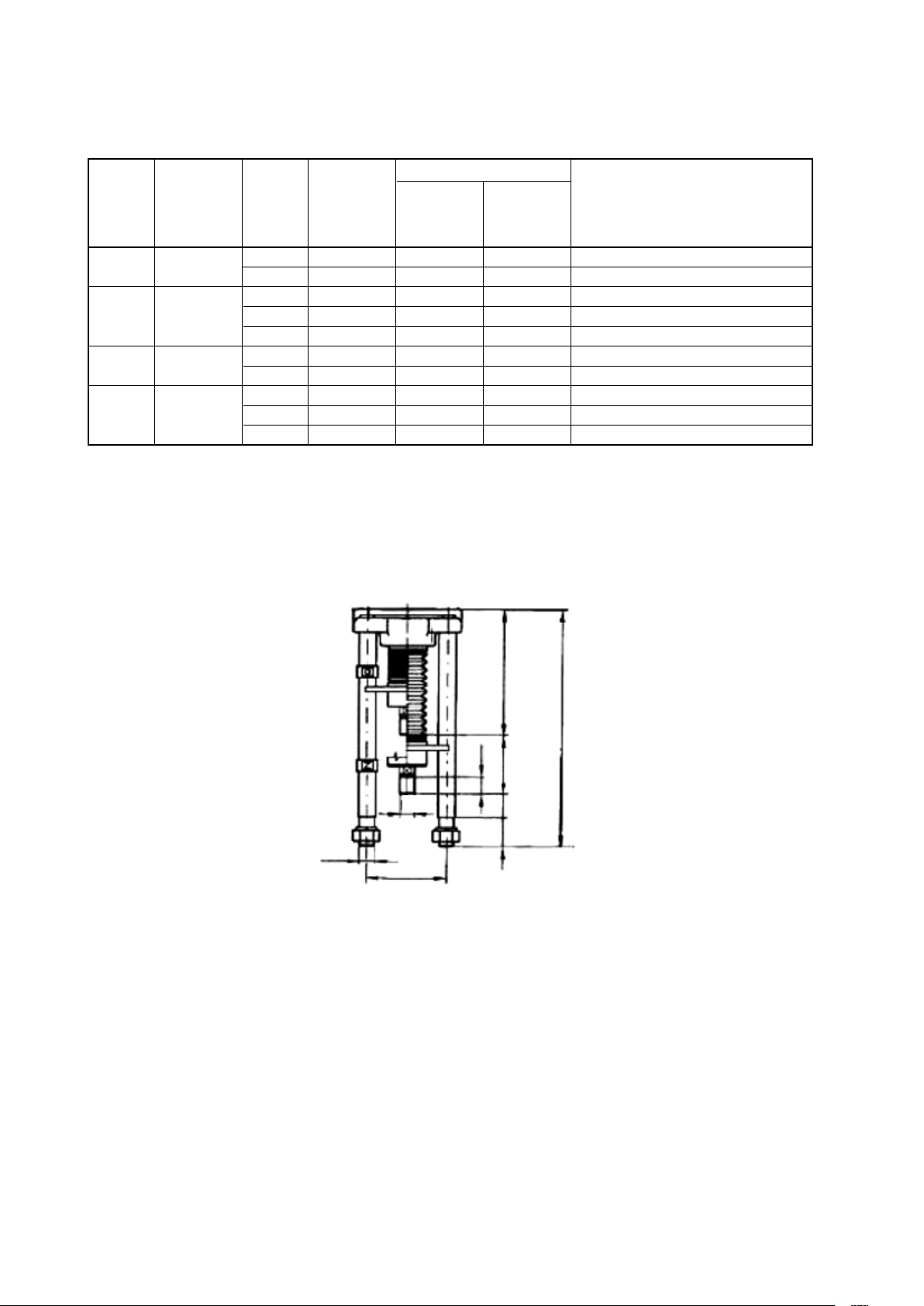
Specific embodiments of the linear thrust device is a combination of letters
and numbers in the following order:
Order of
device
designation
code
1
2
3
4
Dimension of
connection
parameter
Spacing of
columns
Position
“CLOSED”
End of
columns
Thread in
coupling
Code of
dimension
designation
A
B
a
b
g
1
2
I
II
III
Dimension Note
160 mm
150 mm
30 mm
74 mm
130 mm
c = 323 mm
d = 367 mm
h = 423 mm
Endpoint 1
Endpoint 2
M20x1,5
M16x1,5
M10x1
Device height
Endpoint 1 Endpoint 2
c = 308 mm
d = 352 mm
h = 408 mm
a – Short columns
b – Long columns
c – Column length 130 mm
M20 thread 40 mm length with nut
M20 thread 25 mm length
after agreement with the manufacturer
For example, design Aa1I indicates linear thrust device MT15 and MT25 with a spacing of columns 160 mm,
distance of 30 mm from the end of the coupling to the end of the columns in the “closed” position, end of the columns
in design 1 with thread in the coupling M20 x 1,5.
Dimensional sketch of MT40 and MT63 linear thrust device
M30
(257)
485
36
M30x2
60 48 120
160
31

Internal wiring diagrams of MODACT MO EEx electric actuators
Legend:
BQ1 (V1) – Position transmitter - resistance 1x100
CPT 1Az – Current position transmitter
SQ1 (MO) – OPEN torque-limit switch
SQ2 (MZ) – CLOSE torque-limit switch
SQ3 (PO) – OPEN position-limit switch
Positions of the switches: L – Local; R – Remote; O – Open; C – Close
Ω
SQ5 (PZ) – CLOSE position-limit switch
SQ4 (SO) – OPEN signalling switch
SQ6 (SZ) – CLOSE signalling switch
EH (R) – Anti-condensation heaters
T1, T2 – Thermistors
Notes:
should be interconnected with the circuits of thermistor protection of motors (e.g. Siemens Sirius 3RN1). These circuits are not
supplied by ZPA Pečky.
the current transmitter with electric earth of the associated regulator, computer etc. The connection should be realized only
at a single point in any section of the circuit outside the electric actuator. Voltage between the electronics and the case of the
current transmitter must not exceed 50 V DC.
Some electric motors are fitted with thermistors (see Sheet 13, Note 4 of TP 12-02/92, dashed line here). The thermistors
In the design version with the current transmitter CPT 1Az, the user shall provide for connection of the two-wire circuit of
Internal wiring diagrams of MODACT MO EEx electric actuators
– Design with resistance position transmitter MEGATRON 1 x 100 Ω or without transmitter
T1/11
T2/12
Electric motor Control box External protective terminal
– Design with current position transmitter
T1/11
T2/12
Electric motor Control box External protective terminal
CPT 1Az
32

Internal wiring diagrams of MODACT MO EEx electric actuators
version without signaling change-over switches with two doubled position change-over switches.
The doubled position change-over switches (PO1, PO2, and PZ1, PZ2) always switch at the same time
– Design with resistance position transmitter MEGATRON 1 x 100 Ω or without transmitter
T1/11
T2/12
Electric motor Control box External protective terminal
– Design with current position transmitter
T1/11
T2/12
Electric motor Control box External protective terminal
CPT 1Az
33

Internal wiring diagram of MODACT MO EEx electric actuators
of mining version I M2
Electric outfit and wiring according to wiring diagram P-0767 is certified for using actuators in spar-safe control
circuits. The signalling switches, anti-condensation heater, and resistance transmitter are optional accessories.
Control box
Bushing
Switchboard box
Electric motor
(it does not ensure
spark safety)
Control and switchboard box (spark safety is ensured provided that the elements are connected
to spark-safe circuits only)
Conditions of spark-safe protection
– Individual circuits of the actuator can be connected to independent spark-safe circuits provided that the above
mentioned electric parameters are abided.
– No other than spark-safe circuits may be connected to the terminals.
– Connected conductors must be insulated to the metal part of the terminal so that spark-safe surface and air
distances would be observed.
Under these conditions, the actuator provides for level of protection of spark safety “ib” as a simple device according
to ČSN EN 60079-11.
34

P1034
CO
Signalization of
the state
of control:
Local / Remote
– design with potentiometer MEGATRON 1 x 100 Ω,
– design with four-pole change-over switch “local - remote”
Internal wiring diagram of MODACT MO EEx electric actuators
Electric motor Terminal Block actuator Terminal Blocks
of Switches local control
Simulation of control
from the control
system.
O C
35

P1035
CO
– design with potentiometer MEGATRON 1 x 100 Ω,
– design with two-pole change-over switch “local - remote”
Internal wiring diagram of MODACT MO EEx electric actuators
Electric motor Terminal Block actuator Terminal Blocks
of Switches local control
Simulation of control
from the control
system.
O C
36

P-0911
CPT 1Az
CO
Signalizace stavu
ovládání M/O
– provedení s proudovým vysílačem polohy,
– provedení s čtyřpólovým vypínačem „místní“ - „dálkové“
Schéma vnitřního elektrického zapojení servomotorů MODACT MO EEx
Electric motor Terminal Block actuator Terminal Blocks
of Switches local control
Simulation
of control
from the
control
system.
O C
(Example of actuator wiring)
37

P-0912
CO
CPT 1Az
– design with current position transmitter
– design with two-pole change-over switch “local - remote”
Internal wiring diagram of MODACT MO EEx electric actuators
Electric motor Terminal Block actuator Terminal Blocks
of Switches local control
Simulation
of control
from the
control
system.
O C
(Example of actuator wiring)
38

LIST OF SPARE PARTS
(for five year operation)
Type
Name Drawing or pcs Application
no. standard no.
1 2 3 4 5
52 120 Sealing ring 125x3 PN 029281.2 2 Packing between power gear
2327311049 box and flange with gears
Sealing ring 170x3 PN 029281.2 1 Packing of terminal box cover
2327311054
Sealing ring 130x3 PN 029281.2 2 Packing between control box,
2327311041 between flange and power gear box
Sealing ring 43x35 PN 029280.2 1 Packing of output shaft in control box
2327311008
Sealing ring 10x6 PN 029280.2 2 Packing of torque-limit switching shaft
2327311001
Sealing ring 180x3 PN 029281.2 1 Packing of terminal box cover
2327311043
“Gufero” ring 40x52x7 ČSN 029401.0 1 Packing of output shaft in control box
2327352066
Sealing ring 16x12 PN 029280.2 1 Packing of handwheel shaft
2327311025
Packing 224612280 1 Hole cover gasket for rising spindle
of valve
Micro-switch SAIA XGK 12-88-J21 available 1 Open and Close torque-limit switches
2337441060 from ZPA Pečky a.s.
Micro-switch D 433-B8LD available 1 Open and Close position-limit switches
2337441098 from ZPA Pečky a.s. Open and Close signalling switches
“Gufero” ring 40x52x7 ČSN 029401.0 2
2327352066
“Gufero” ring 16x28x7 ČSN 029401.0 1 Packing of handwheel shaft
2327352022
Packing 16x22 224580840 2 Packing of threaded plug (for oil filling)
Packing 224635220 1 Packing between control and terminal
boxes
Packing of output shaft in power gear box
52 121 Micro-switch SAIA XGK 12-88-J21 available 1 Open and Close torque-limit switches
+ 2337441060 from ZPA Pečky a.s.
52 122
“Gufero” ring 60x75x8 ČSN 029401.0 2 Packing of output shaft in power gear
2327352090 box
“Gufero” ring 20x32x7 ČSN 029401.0 1 Packing of handwheel shaft
2327352027
Sealing ring 95x85 PN 029280.2 1 Packing of insertion with “Gufero” rings
2327311029 in power gear box
Sealing ring 50x2 PN 029281.2 1 Packing of cover of torque-limit
2327311028 switching spring
Sealing ring 16x22 224580840 2 Packing of threaded plug (for oil filling)
39

1 2 3 4 5
Packing 224642240 1 Packing between electric motor
and flange with gears
Micro-switch D 433-B8LD available 1 Open and Close position-limit switches
2337441098 from ZPA Pečky a.s. Open and Close signalling switches
Sealing ring 160x3 PN 029281.2 1 Packing between power gear box
2327311048 and flange with gears
Sealing ring 170x3
2327311054 PN 029281.2 1 Packing of terminal box cover
Sealing ring 190x3 PN 029281.2 1 Packing between control box
2327311056 and power gear box
“Gufero” ring 55x70x8 ČSN 029401.0 1 Packing of output shaft in control box
2327352083
Sealing ring 10x6 PN 029280.2 2 Packing of torque-limit switching shaft
2327311001
Sealing ring 200x3 PN 029281.2 2 Packing of terminal box cover
2327311044
Packing, size 3 224610741 1 Hole cover gasket for rising spindle
of valve
Sealing ring 60x50 PN 029280.2 1 Packing of output shaft in control box
2327311090
52 123 Sealing ring 220x3 PN 029281.2 1 Packing of control box cover
+ 2327311045
52 124
“Gufero” ring 80x100x10 ČSN 029401.0 1 Packing of output shaft in control box
2327352096
Sealing ring 10x6 PN 029280.2 2 Packing of torque-limit switching shaft
2327311001
Sealing ring 85x75 PN 029280.2 1 Packing of output shaft in control box
2327311087 cover
Sealing ring 25x21 PN 029280.2 1 Packing of handwheel shaft
2327310999
Packing 224637080 1
of valve
Micro-switch SAIA XGK 12-88-J21 available 1 Open and Close torque-limit switches
2337441060 from ZPA Pečky a.s.
“Gufero” ring 80x100x10 ČSN 029401.0 1
2327352096
“Gufero” ring 27x40x10 ČSN 029401.0 1 Packing of handwheel shaft
2327352044
Sealing ring 70x2 PN 029281.2 1 Packing of cover of torque-limit
2327311058 switching spring
Sealing ring 200x3 PN 029281.2 1 Packing between power gear box
2327311044 and flange with gears
Packing 16x22 224580840 2 Packing of threaded plug (for oil filling)
Packing 224635220 1 Packing between control and terminal
boxes
Hole cover gasket for rising spindle
Packing of output shaft in power gear box
40

1 2 3 4 5
Micro-switch D 433-B8LD available 1 Open and Close position-limit switches
2337441098 from ZPA Pečky a.s. Open and Close signalling switches
Packing 224591530 1 Packing between electric motor
and flange with gears
Sealing ring 200x3 PN 029281.2 1 Packing between power gear box
2327311044 and control box
Sealing ring 170x3 PN 029281.2 1 Packing of terminal box cover
2327311054
52 125 Micro-switch SAIA XGK 12-88-J21 available 1 Open and Close torque-limit switches
2337441060 from ZPA Pečky a.s.
Micro-switch D 433-B8LD available 1 Open and Close position-limit switches
2337441098 from ZPA Pečky a.s. Open and Close signalling switches
Sealing ring 16x22 224580840 2 Packing of threaded plug (for oil filling)
Packing 22459337 1 Packing between electric motor
and flange with gears
Sealing ring 280x3 PN 029281.2 1 Packing between power gear box
2327311078 and flange with gears
“Gufero” ring 105x130x13 ČSN 029401.0 2
2327352109
“Gufero” ring 30x50x12 ČSN 029401.0 1 Packing of handwheel shaft
2327352054
Sealing ring 30x22 PN 029280.2 1 Packing of handwheel shaft
2327311026
Sealing ring 90x2 PN 029281.2 1 Packing of torque-limit switching spring
2327311081 cover
“Gufero” ring 85x110x12 ČSN 029401.0 1 Packing of output shaft in control box
2327352099
Sealing ring 260x5 PN 029281.2 1 Packing between power gear box and
2327311046 control box
Sealing ring 220x3 PN 029281.2 1 Packing of control box cover
2327311045
Sealing ring 10x6 PN 029280.2 2 Packing of torque tripping shaft
2327311001
Sealing ring 90x80 PN 029280.2 1 Packing of output shaft in control box
2327311011 cover
Packing 224637080 1 Hole cover gasket for rising spindle of valve
Packing 224635220 1
Packing of output shaft in power gear box
Packing between control and terminal boxes
Sealing ring 170x3 PN 029281.2 1 Packing of terminal box cover
2327311054
Position transmitters
52 120 Potentiometer 1 x 100 Ω 214628653 1 To be mounted on control board
99557-3
52 121-5 Potentiometer 1 x 100 Ω 2340510282 1 To be mounted on control board
99557-3
52 120-5 Current position transmitter CPT 1Az 2340510393 1 To be mounted on control board
41

NOTES
42

Development, production and services of electric actuators and switchboards.
Top-quality sheet-metal processing (TRUMPF equipment), powder paint shop.
SURVEY OF PRODUCED ACTUATORS
KP MINI, KP MIDI
Electric rotary (90°) actuators (up to 30 Nm)
MODACT MOK, MOKED, MOKP Ex, MOKPED Ex
Electric rotary (90°) actuators for ball valves and flaps
MODACT MOKA
Electric rotary (90°) actuators for nuclear power stations
application outside containment
MODACT MON, MOP, MONJ, MONED, MOPED, MONEDJ
Electric rotary multi-turn actuators
MODACT MO EEx, MOED EEx
Explosion proof electric multi-turn actuators
MODACT MOA
Electric multi-turn actuators for nuclear power stations
application outside containment
MODACT MOA OC
Electric multi-turn actuators for nuclear power stations
application inside containment
MODACT MPR Variant
Electric rotary (160°) lever actuators with a variable output speed
MODACT MPS, MPSP, MPSED, MPSPED
Electric rotary (160°) lever actuators with a constant output speed
MODACT MTN, MTP, MTNED, MTPED
Electric linear thrust actuators with a constant output speed
Deliveries of assembled actuator + valve (or MASTERGEAR gearbox) combinations
TRADITION
•
QUALITY
•
RELIABILITY

ZPA Pečky, a.s.
tř. 5. května 166
289 11 PEČKY, Czech Republic
www.zpa-pecky.cz
tel.: +420 321 785 141-9
fax: +420 321 785 165
+420 321 785 167
e-mail: zpa@zpa-pecky.cz
 Loading...