

Page 1
Page 2
1
Federal Communications Commission (FCC) Statement
This equipment has been tested and found to comply with the limits for a Class B digital device,
pursuant to Part 15 of FCC Rules. These limits are designed to provide reasonable protection
against harmful interference in a residential installation. This equipment generates, uses and
can radiate radio frequency energy and, if not installed and used in accordance with instructions
contained in this manual, may cause harmful interference to radio and television communications.
However, there is no guarantee that interference will not occur in a particular installation.
If this equipment does cause harmful interference to radio or television reception, which can
be determined by turning the equipment off and on, the user is encouraged to try to correct the
interference by one or more of the following measures:
- REORIENT OR RELOCATE THE RECEIVING ANTENNA
- INCREASE THE SEPARATION BETWEEN THE EQUIPMENT AND THE RECEIVER
- CONNECT THE EQUIPMENT INTO AN OUTLET ON A CIRCUIT DIFFERENT FROM
THAT OF THE RECEIVER
- CONSULT THE DEALER OR AN EXPERIENCED AUDIO/TELEVISION TECHNICIAN
NOTE:
Connecting this device to peripheral devices that do not comply with Class B requirements, or
using an unshielded peripheral data cable, could also result in harmful interference to radio or
television reception.
The user is cautioned that any changes or modications not expressly approved by the party
responsible for compliance could void the user’s authority to operate this equipment.
To ensure that the use of this product does not contribute to interference, it is necessary to use
shielded I/O cables.
Copyright
This manual is copyrighted with all rights reserved. No portion of this manual may be copied or
reproduced by any means.
While every precaution has been taken in the preparation of this manual, no responsibility for
errors or omissions is assumed. Neither is any liability assumed for damages resulting from the
use of the information contained herein.
Trademarks
All brand names, logos and registered trademarks mentioned are property of their respective
owners.
Electronic Emission Notices
WARNING!
Page 3

2
Intel® NM10-ITX series Motherboard
Table of Contents
Motherboard Specications ---------------------------------------------------------------------------------4
Motherboard Layout--------------------------------------------------------------------------------------------6
Hardware Installation ------------------------------------------------------------------------------------------ 9
Safety Instructions -------------------------------------------------------------------------------------------9
Installing Memory DIMMs ---------------------------------------------------------------------------------10
Installing the Motherboard ---------------------------------------------------------------------------------11
Installing the I/O Shield ------------------------------------------------------------------------------------11
Securing the Motherboard into the Chassis ----------------------------------------------------------11
Connecting Cables and Setting Switches --------------------------------------------------------------12
20-pin ATX Power Connector-PW1 ---------------------------------------------------------------------13
4-pin ATX_12V power connector-PW2 ----------------------------------------------------------------- 13
SPDIF-Out Header-CN6 ----------------------------------------------------------------------------------- 14
COM Header-COM1 ---------------------------------------------------------------------------------------- 14
Front panel header-FP1 -----------------------------------------------------------------------------------14
USB Header-FP_U1 ----------------------------------------------------------------------------------------15
Front Pannel Audio Header-FP_S1 ---------------------------------------------------------------------15
Speaker Header-SPK1 -------------------------------------------------------------------------------------16
Fan Connectors ----------------------------------------------------------------------------------------------16
Serial-ATA (SATA) Connectors (SATA1~2) ------------------------------------------------------------16
Expansion Slots ---------------------------------------------------------------------------------------------- 17
Mini PCIE Slots ------------------------------------------------------------------------------------------17
PCIE x1 Slot ----------------------------------------------------------------------------------------------17
Jumper Settings ----------------------------------------------------------------------------------------------17
Conguring the BIOS ------------------------------------------------------------------------------------------18
Enter BIOS Setup -------------------------------------------------------------------------------------------------18
Main Menu -----------------------------------------------------------------------------------------------------18
Advanced Menu ----------------------------------------------------------------------------------------------19
CPU Conguration --------------------------------------------------------------------------------------19
IDE Conguration ---------------------------------------------------------------------------------------19
Hardware Health Conguration ---------------------------------------------------------------------20
ACPI Conguration -------------------------------------------------------------------------------------20
MPS Conguration --------------------------------------------------------------------------------------20
PCI Express Conguration ----------------------------------------------------------------------------20
Smbios Conguration ----------------------------------------------------------------------------------20
USB Conguration --------------------------------------------------------------------------------------20
PCIPnP Menu ------------------------------------------------------------------------------------------------21
Boot Menu -----------------------------------------------------------------------------------------------------22
Security Menu ------------------------------------------------------------------------------------------------23
Chipset Menu ------------------------------------------------------------------------------------------------- 24
Exit Menu ------------------------------------------------------------------------------------------------------24
Page 4

3
Table of Contents
Flash Update Procedure ---------------------------------------------------------------------------------- 25
Installing Drivers and Software ---------------------------------------------------------------------------- 26
Driver Installation ------------------------------------------------------------------------------------------- 26
The adjustment of graphics properties ----------------------------------------------------------------- 33
Realtek HD Audio Driver Setup ----------------------------------------------------------------------------35
Getting Started -----------------------------------------------------------------------------------------------35
Sound Effect --------------------------------------------------------------------------------------------------35
Environment Simulation ------------------------------------------------------------------------------------35
Equalizer Selection ----------------------------------------------------------------------------------------- 36
Frequently Used Equalizer Setting ----------------------------------------------------------------------36
Karaoke Mode ------------------------------------------------------------------------------------------------ 36
Mixer ------------------------------------------------------------------------------------------------------------ 37
Playback control ---------------------------------------------------------------------------------------- 37
Recording control -------------------------------------------------------------------------------------- 38
Audio I/O -------------------------------------------------------------------------------------------------39
Speaker Conguration -------------------------------------------------------------------------------- 40
Connector Settings ------------------------------------------------------------------------------------ 41
S/PDIF ----------------------------------------------------------------------------------------------------41
Speaker Calibration ------------------------------------------------------------------------------------42
Microphone ----------------------------------------------------------------------------------------------43
Noise Suppression -------------------------------------------------------------------------------------43
Beam Forming ------------------------------------------------------------------------------------------43
Acoustic Echo Cancellation --------------------------------------------------------------------------43
Audio Demo----------------------------------------------------------------------------------------------44
Information ----------------------------------------------------------------------------------------------44
Page 5

4
Intel® NM10-ITX series Motherboard
Motherboard Specications
q Chipset
v Intel® NM10 Family Express Chipset
q Size
v mini ITX form factor of 6.7 X 6.7 inch
q Microprocessor support
v Integrated with Intel® AtomTM processor D4/D5 series featuring an integrated graphics core
(Intel® GMA 3150) with graphics performance improvements
v Supports Front Side Bus (FSB) Frequency of 667 MHz
q Operating systems
v Supports Windows XP 32 bit/64 bit, Windows Vista 32 bit/64 bit and Windows 7 32bit/64bit
q System Memory
v Supports single-channel DDR2 800/667 SDRAM
v Supports two unbuffered DIMMs
v Maximum memory size: 4 GB
q USB 2.0 ports
v Supports hot plug and play
v Eight USB 2.0 ports (six rear panel ports, two from onboard USB header)
v Supports USB 2.0 protocol up to 480 Mbps transmission rate
q Onboard Serial ATA
v Independent DMA operation on two ports (Optional)
v Data transfer rates of 3.0 Gb/s
q Onboard Lan
v PCI Express base specication 1.0a compliant
v Compliant to 802.3x ow control support
v Wake On LAN (WOL) power management support
v RTL8111DL is Gigabit Ethernet controller
q Onboard High Denition Audio
v Supports 6-channel
v Supports Jack-Sensing function
v One SPDIF-out header on board
q Green Function
v Support SMM, APM, ACPI
v Suspend to DRAM supported (STR)
Page 6

5
Motherboard Specications
v RTC timer to power-on the system
v AC power failure recovery
q Graphics Processing Unit Features
v Integrated with Intel® GMA 3150
v Direct X9 compliant Pixel Shader v2.0
v 3D Graphics Rendering Enhancements
v HDMI port output support (Optional)
q PCI Express Interface
v Provide 250 MB/s bandwidth for platform graphics
v Wake up function is supported
v Clock spread spectrum capability
q Expansion slots
v One PCI express X1 slot
v Two MINI PCI express slots
Page 7
6
Intel® NM10-ITX series Motherboard
Motherboard Layout
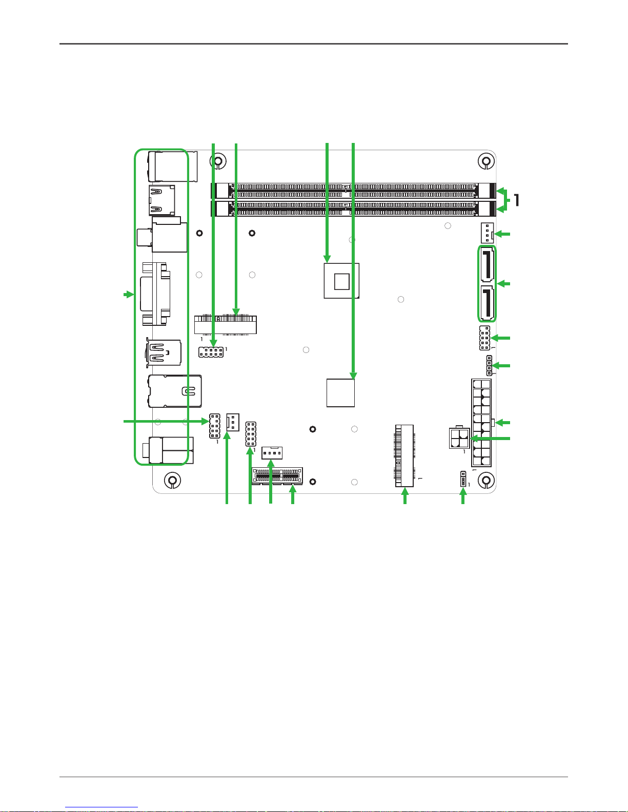
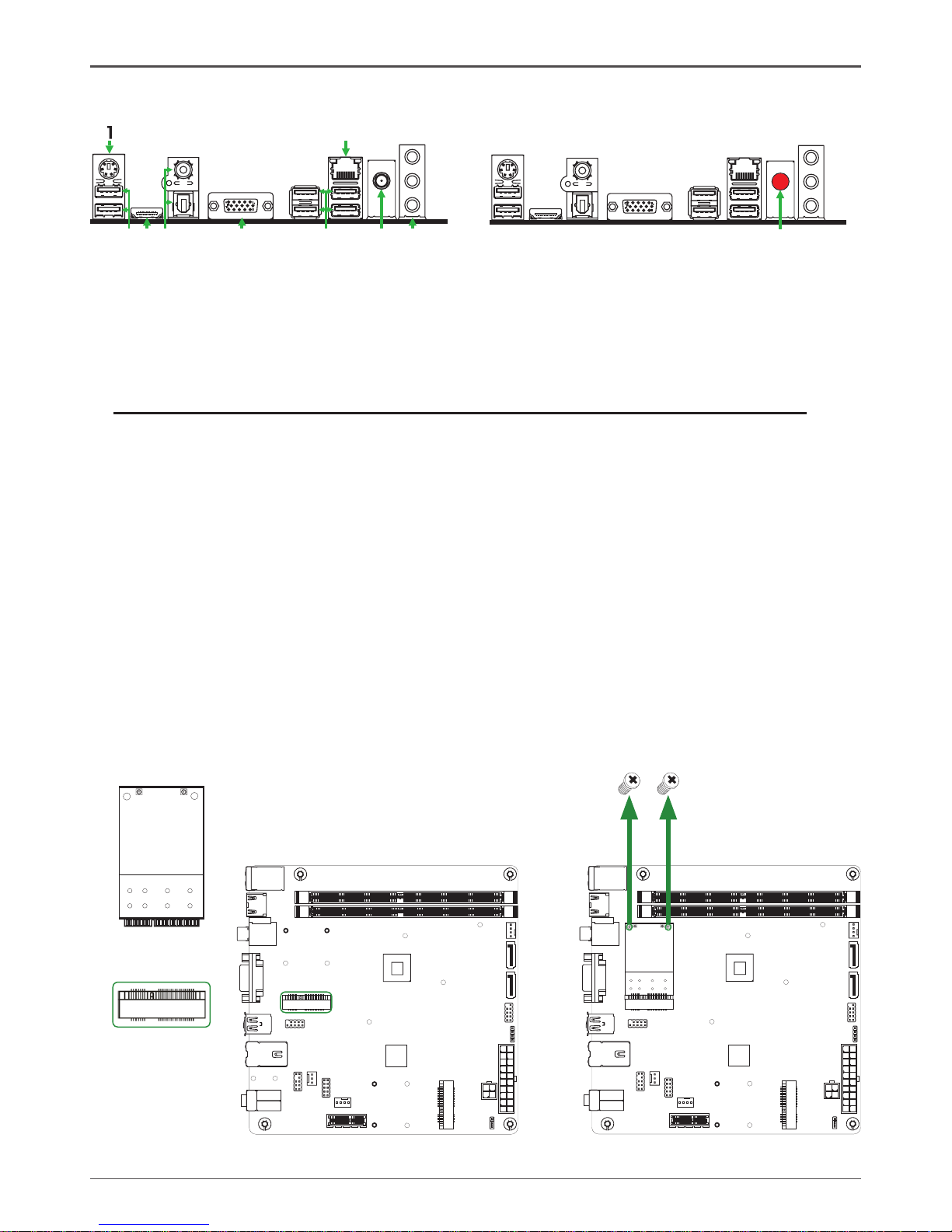
Figure 1 shows the motherboard and Figure 2 shows the back panel connectors.
Figure 1. Board Layout
1. DDRII DIMM Sockets-DDRII1~2
2. CPU Fan Connector-CPUFAN
3. Serial-ATA (SATA) Connectors (SATA1~2)
4. Front Panel Header-FP1
5. Speaker Header-SPK1
6. 20-pin ATX Power Connector-PW1
7. 4-pin ATX_12V power connector-PW2
8. Clear CMOS Jumper-JP1
9. Mini PCIE Slot-M_PCIE1
10. PCI Express x1 Slot-PCIEX1
11. SYS Fan Connector-SYSFAN
12. COM Header_COM1
13. SPDIF-Out Header-CN6
14. Front pannel audio Header-FP_S1
15. Backpanel connectors
16. USB Headers-FP_U1
17. Mini PCIE Slot-M_PCIE2
18. Onboard CPU
19. Chipset
Figure 1
120
240
121
120
240
121
Chi ps et
DDR II -1
DDR II -2
PW1
SYS FAN_
FP1
SATA 1
SATA 2
PCI EX 1
CPU FAN_
USB
JP1
PW2
HDM I
VGA
LA N USB/
SD1
KB
USB/
SPD IF
2
3
4
5
6
8
7
9
10
11
12
13
14
15
SPK 1
16
M_P CI E1
17
2
51
52
COM 1
CN6
FP_ S1
FP_ U1
M_P CI E2
2
51
52
CPU
18 19
Page 8
7
Rear panel
1. PS/2 Keyboard Port
3. HDMI Port (Optional)
5. VGA Port
2. USB Connectors
4. SPDIF Connectors
6
11
5
10
15
2 2
3
4
5
7
68
Figure 2
6
11
5
10
15
8
7. LAN Connector
Lan Port with LEDs to indicate status.
· Yellow/Light Up/Blink = 10 Mbps/Link/Activity
· Yellow and Green/Light Up/Blink = 100 Mbps/link/Activity
· Yellow and Orange/Light Up/Blink = 1000 Mbps/link/Activity
6. Port 2-Channel 4-Channel 6-Channel
Blue Line-In Rear Speaker Out Rear Speaker Out
Green Line-Out Front Speaker Out Front Speaker Out
Pink Mic In Mic In Center/Subwoofer
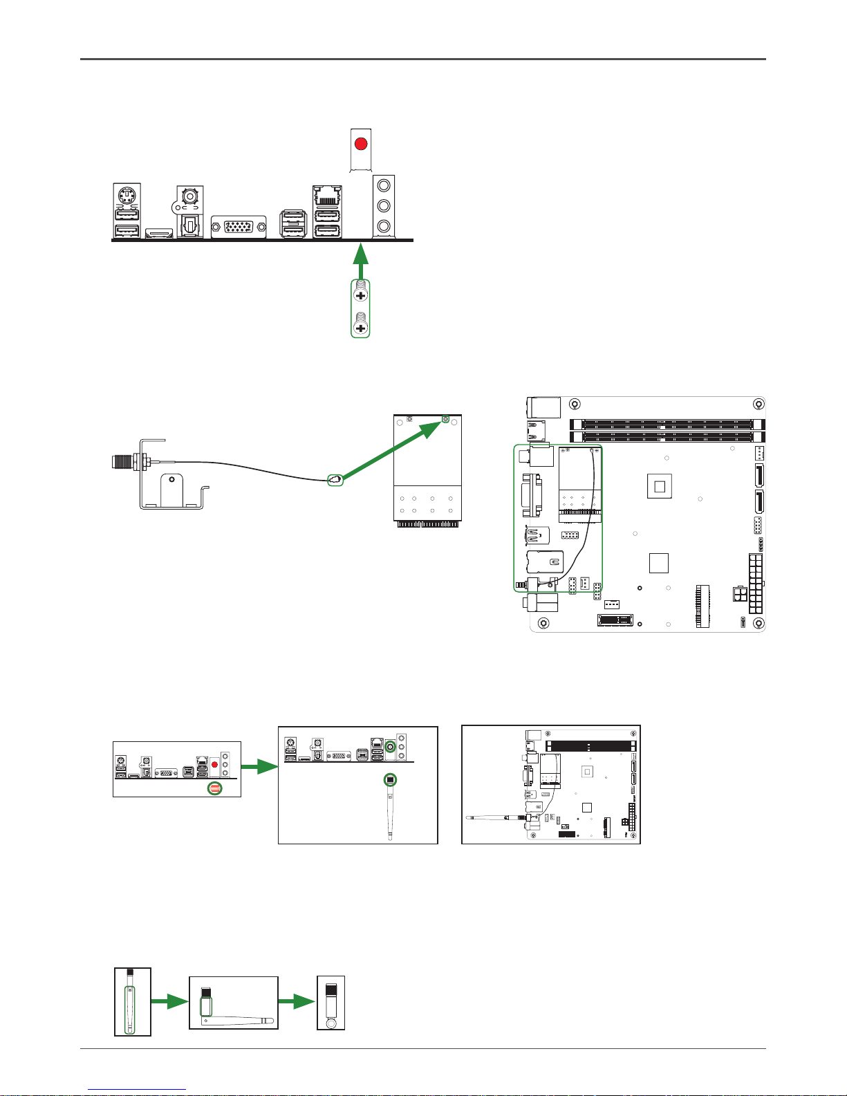
8. WiFi antenna connector (Optional)
Refer to the following to install the WiFi antenna modules.
Step 1. Secure the MINI PCIE card into the M_PCIE1/M_PCIE2 slot with screws.
120
240
121
120
240
121
M_PCIE1/2 slot
MINI PCIE card
120
240
121
120
240
121
Screws
Page 9
8
Intel® NM10-ITX series Motherboard
120
240
121
120
240
121
Step 4. Remove the red cap from the WiFi antenna connector.
Install the WiFi antenna to the WiFi antenna connector, and make sure the screw is
rotated in clockwise direction.
Note: 1. Users please note that the appearance of your WiFi antenna modules may
not be exactly the same as those shown in this manual.
2. Users can bend or rotate the WiFi antennas to the best receiving direction
according to the picture below.
Step 2. Secure the bracket to the motherboard with screws according to the picture below.
120
240
121
120
240
121
6
11
5
10
15
Screws
Bracket
Step 3. Connect the WiFi wire to the MINI PCIE card as the following picture shows.
MINI PCIE card
Bracket
WiFi wire
6
11
5
10
15
6
11
5
10
15
Page 10

9
Hardware Installation
This section will guide you through the installation of the motherboard. The topics covered in this
section are:
q Installing Memory DIMMs
q Installing the motherboard
q Installing the I/O Shield
q Connecting cables and setting switches
Safety Instructions
To reduce the risk of re, electric shock, and injury, always follow basic safety precautions.
Remember to remove power from your computer by disconnecting the AC main source before
removing or installing any equipment from/to the computer chassis.
Hardware Installation
Page 11
10
Intel® NM10-ITX series Motherboard
Installing Memory DIMMs
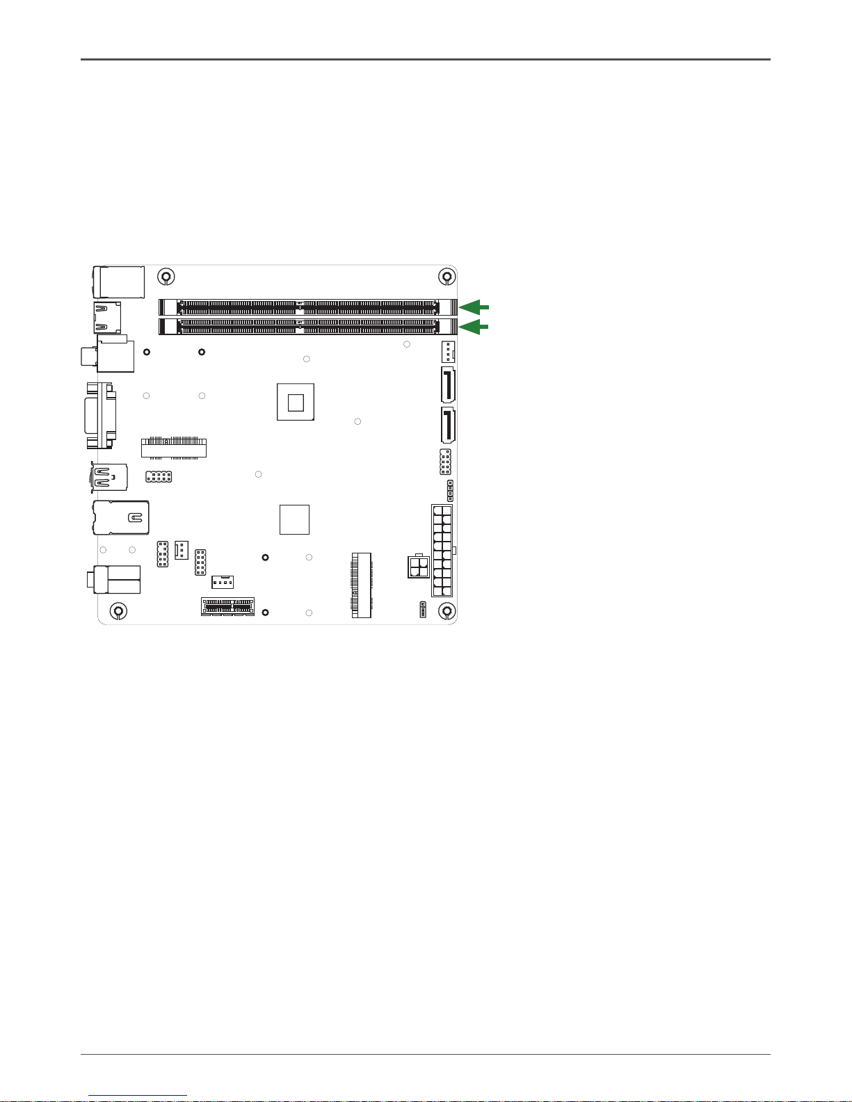
This motherboard accommodates two memory modules. It can support two 240-pin DDR2
800/667. The total memory capacity is 4 GB. You must install at least one module in any of the
two slots. Refer to the following recommendations to install the memory modules.
q One DIMM: Install it into slot 1 or 2. You can install the DIMM into any slot, however, slot 1
is preferred.
q Two DIMMs: Install them into slot 1 and slot 2
Refer to the following procedure to install the memory modules. Note that there is only one gap
near the center of the DIMM slot. This slot matches the slot on the memory DIMM to ensure the
component is installed properly.
1. Unlock a DIMM slot by pressing the module clips outward.
2. Align the memory module to the DIMM slot, and insert the module vertically into the DIMM
slot. The plastic clips at both sides of the DIMM slot automatically lock the DIMM into the
connector.
120
240
121
120
240
121
DDRII-1
DDRII-2
Page 12

11
Installing the Motherboard
The sequence of installing the motherboard into the chassis depends on the chassis you are
using and if you are replacing an existing motherboard or working with an empty chassis. Deter-
mine if it would be easier to make all the connections prior to this step or to secure the mother-
board and then make all the connections. It is normally easier to secure the motherboard rst.
Use the following procedure to install the I/O shield and secure the motherboard into the chassis.
Note: Be sure that the CPU fan assembly has enough clearance for the chassis covers
to lock into place and for the expansion cards. Also make sure the CPU Fan assem
-bly is aligned with the vents on the covers.
Installing the I/O Shield
The motherboard kit comes with an I/O shield that is used to block radio frequency transmis-
sions, protects internal components from dust and foreign objects, and promotes correct airow
within the chassis.
Before installing the motherboard, install the I/O shield from the inside of the chassis. Press the
I/O shield into place and make sure it ts securely. If the I/O shield does not t into the chassis,
you would need to obtain the proper size from the chassis supplier.
Securing the Motherboard into the Chassis
Most computer chassis have a base with mounting studs or spacers to allow the motherboard
to be secured to the chassis and help to prevent short circuits. If there are studs that do not
align with a mounting hole on the motherboard, it is recommended that you remove that stud
to prevent the possibility of a short circuit. In most cases, it is recommended to secure the
motherboard with spacers.
1. Carefully place the motherboard onto the studs/spacers located inside the chassis.
2. Align the mounting holes with the studs/spacers.
3. Align the connectors to the I/O shield.
4. Ensure that the fan assembly is aligned with the chassis vents according to the fan assembly
instruction.
5. Secure the motherboard with screws.
Page 13

12
Intel® NM10-ITX series Motherboard
Connecting Cables and Setting Switches
This section takes you through all the connectors and switch settings necessary on the mother-
board. This will include:
q Power Connectors
v 20-pin ATX Power Connector-PW1
v 4-pin ATX_12V Power Connector-PW2
q Internal Headers/Connectors
v SPDIF-Out Header-CN6
v COM Header-COM1
v Front Panel Header-FP1
v USB Header-FP_U1
v Front Pannel Audio Header-FP_S1
v Speaker Header-SPK1
q Serial-ATA (SATA) Connectors (SATA1~2)
q Chassis Fan Connectors
q Expansion Slots
q CMOS Jumper Settings
See Figure 1 to locate the connectors and jumpers referenced in the following procedure.
Page 14
13
Hardware Installation
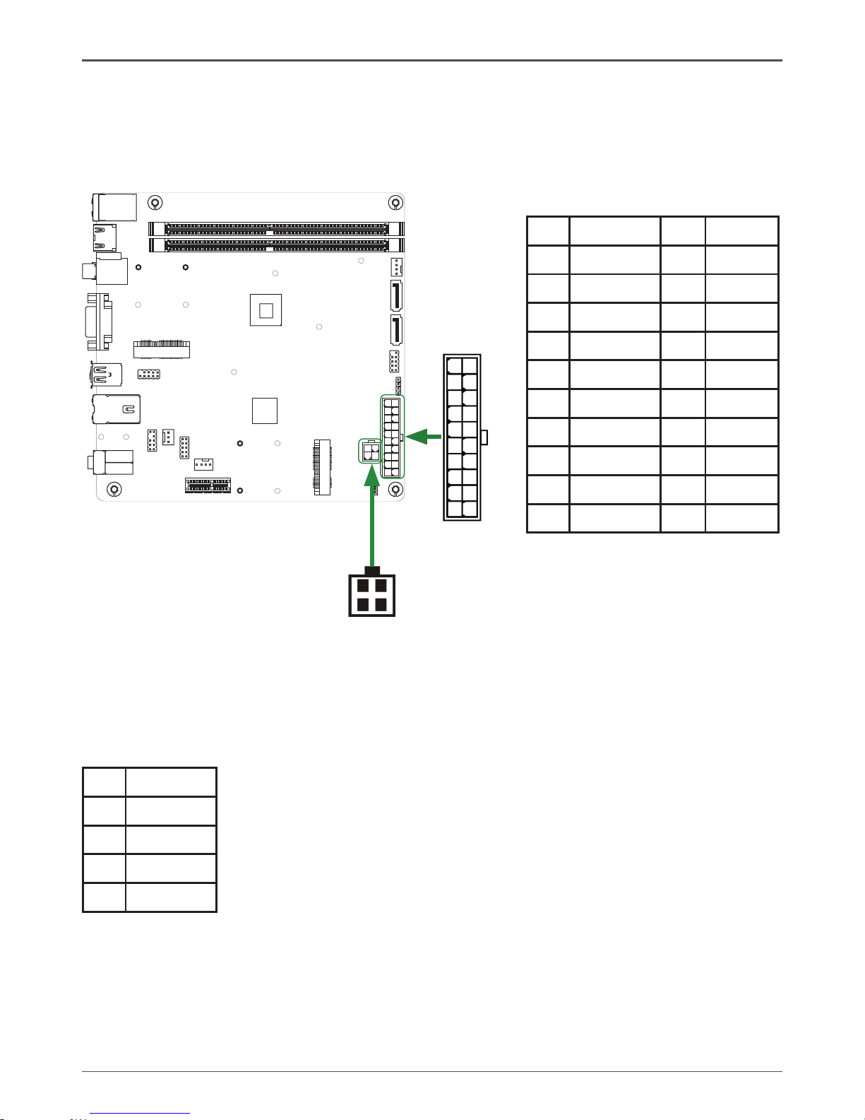
20-pin ATX Power Connector-PW1
PW1 is the main power supply connector. Make sure that the power supply cable and pins are
properly aligned with the connector on the motherboard. Firmly plug the power supply cable into
the connector and make sure it is secure.
4-pin ATX_12V power connector-PW2
PW2, the 4-pin ATX 12V power connection, is used to provide power to the CPU. Align the pins
to the connector and press rmly until seated.
PW2-Pin Denition
Pin Signal
1 GND
2 GND
3 +12V
4 +12V
120
240
121
120
240
121
2
1
4 3
PW2
PW1
1
10
11
20
PW1-Pin Denition
Pin Signal Pin Signal
1 +3.3V 11 +3.3V
2 +3.3V 12 -12V
3 GND 13 GND
4 +5V 14 PS_ON
5 GND 15 GND
6 +5V 16 GND
7 GND 17 GND
8 PWROK 18 -5V
9 +5V_AUX 19 +5V
10 +12V 20 +5V
Page 15
14
Intel® NM10-ITX series Motherboard
120
240
121
120
240
121
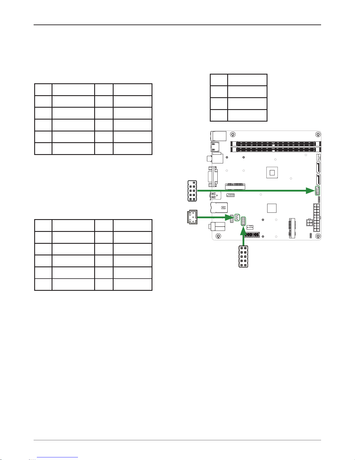
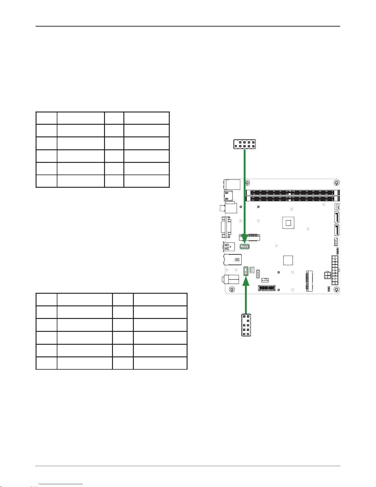
SPDIF-Out Header-CN6
This header provides a SPDIF (Sony/Philips Digital Interface) output to digital multimedia device
through coaxial connector.
CN6 - Pin Denition
Pin Signal
1 GND
2 SPDIF-out
3 VCC
q PWRLED
Attach the front panel power LED cable to these two pins of the connector. The Power LED
indicates the system’s status.
q PWR SW
Attach the power button cable from the case to these two pins. Pressing the power button
on the front panel turns the system on and off rather than using the power supply button.
q HDD LED
Attach the hard disk drive indicator LED cable to these two pins. The HDD indicator LED
indicates the activity status of the hard disks.
q RST SW
Attach the Reset switch cable from the front panel of the case to these two pins. The system
restarts when the RESET switch is pressed.
Note: Some chassis do not have all four cables. Be sure to match the name on the
connectors to the corresponding pins.
FP1-Pin Denition
Pin Signal Pin Signal
1 HDD_LED+ 2 PW_LED+
3 HDD_LED- 4 PW_LED-
5 GND 6 PWR_SW
7 RESET 8 GND
9 NC 10 KEY
CN6
12
910
Front panel header-FP1
The front panel header on this motherboard is
one connector used to connect the following
four cables :
1
FP1
COM1
1
COM1 - Pin Denition
Pin Signal Pin Signal
1 DCD 2 RXD
3 TXD 4 DTR
5 GND 6 DSR
7 RTS 8 CTS
9 RI 10 NC
COM Header-COM1
Page 16
15
Hardware Installation
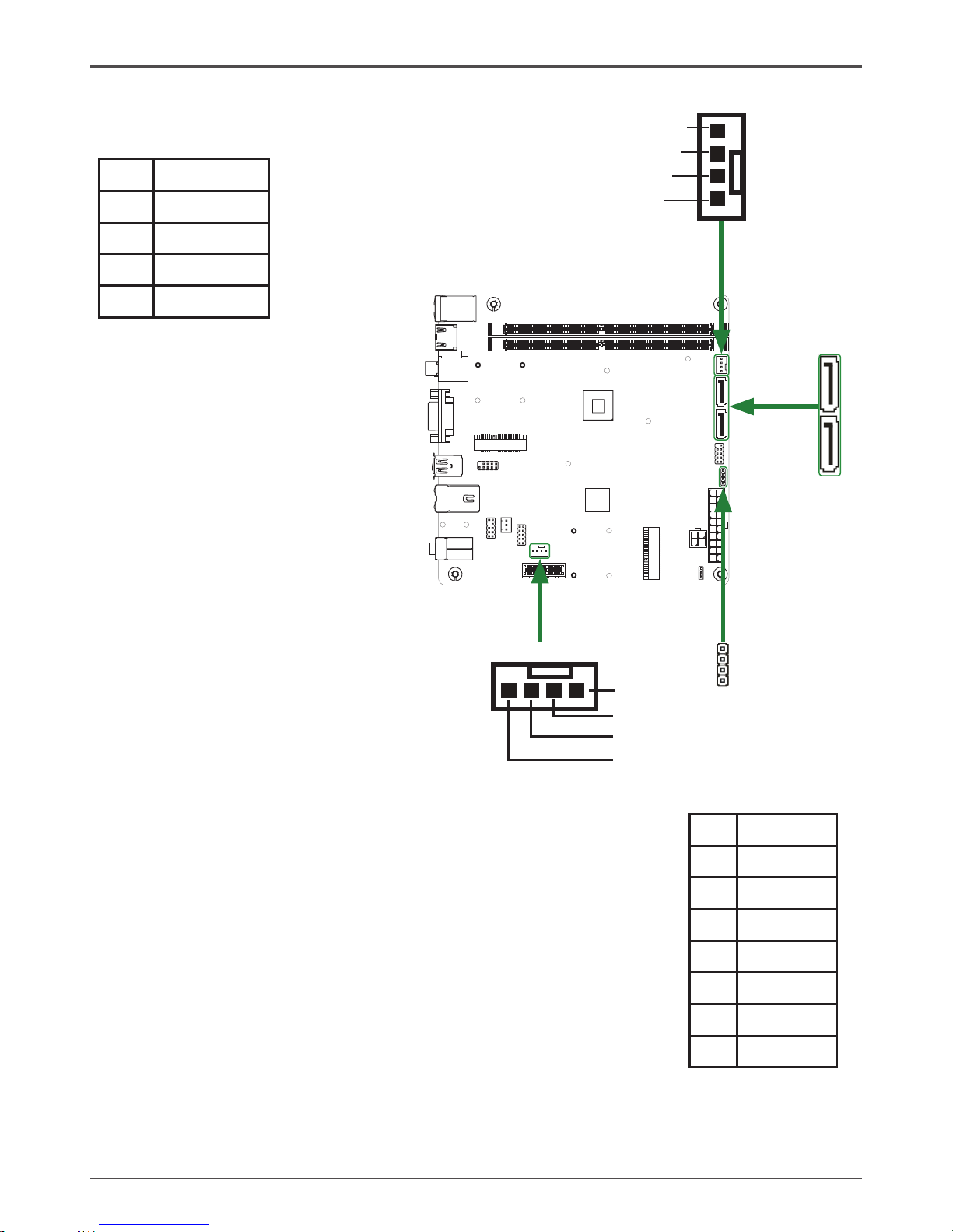
USB Header-FP_U1
This motherboard contains six USB 2.0 ports that are exposed on the rear panel of the chassis.
The motherboard also contains one 10-pin internal header onboard.
Note: Secure the bracket to either the front or rear panel of your chassis (not all chassis
are equipped with the front panel option).
120
240
121
120
240
121
Front Panel Audio Header-FP_S1
The audio connector supports HD audio standard and
provides two kinds of audio output choices: the Front
Audio, the Rear Audio. The front Audio supports re-task-
ing function.
Note:
In order to utilize the front audio header, your chassis must have front audio connector.
Also please make sure the pin assignment on the cable is the same as the pin
assignment on the mainboard header. To nd out if the chassis you are buying supports
a front audio connector, please contract your dealer.
FP_S1-Pin Denition
PIN Assignment PIN Assignment
1 MIC2(L) 2 GND
3 MIC(R) 4 -ACZ-DET
5 Front Audio(R) 6 Reserved
7 FAVDIO-JD 8 Key(No pin)
9 Front Audio(L) 10 Reserved
FP_U1-Pin Denition
PIN Assignment PIN Assignment
1 VCC 2 VCC
3 USBP0- 4 USBP1-
5 USBP0+ 6 USBP1+
7 GND 8 GND
9 KEY 10 NC
19
10 2
FP_U1
2 1
10 9
FP_S1
Page 17
16
Intel® NM10-ITX series Motherboard
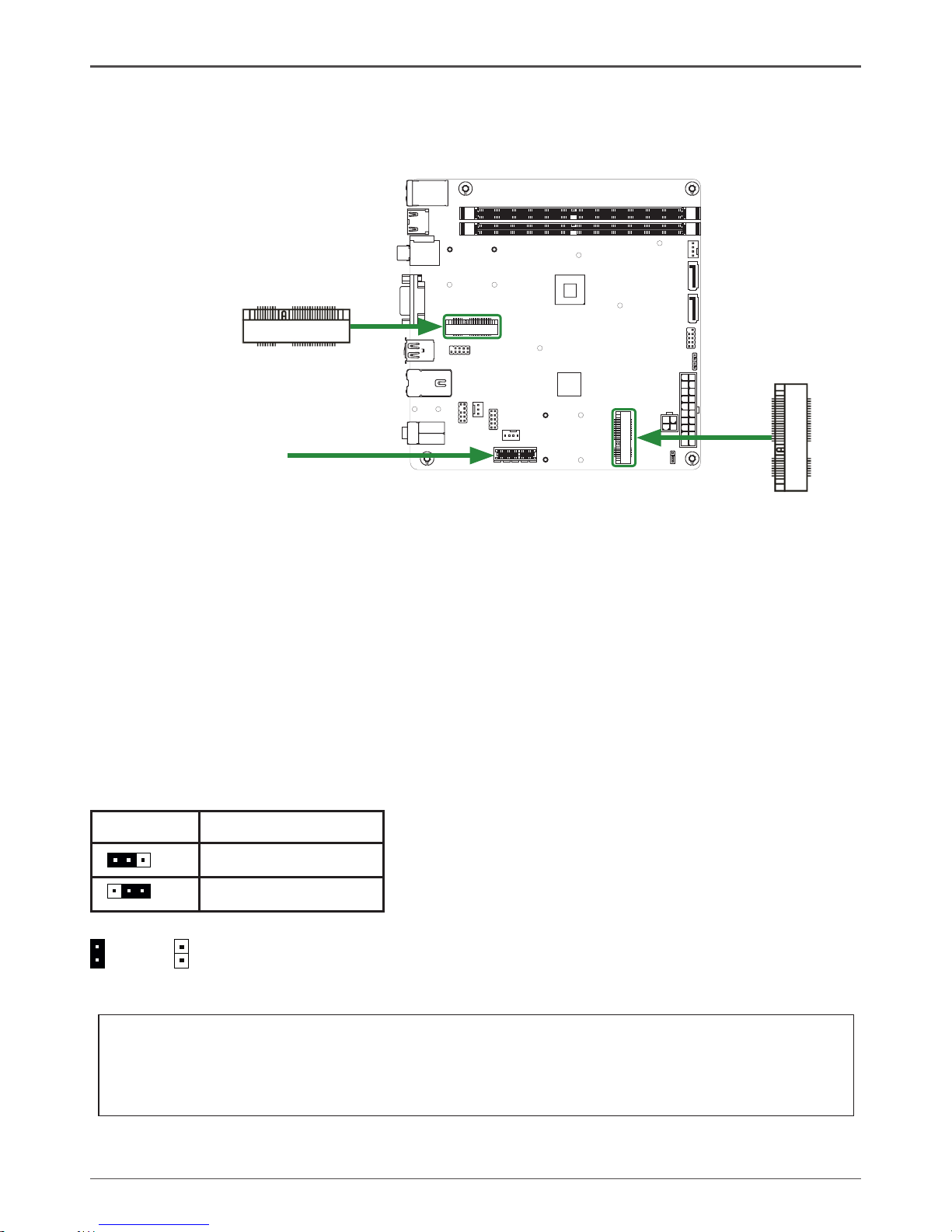
Speaker Header-SPK1
Serial-ATA (SATA) Connectors (SATA1~2)
The Serial ATA connector is used to connect the Serial ATA
device to the motherboard. These connectors support the thin
Serial ATA cables for primary storage devices. The current
Serial ATA interface allows up to 300 MB/s data transfer rate.
There are two serial ATA connectors on the motherboard that
support AHCI conguration.
SPK1-Pin Denition
PIN Assignment
1 VCC
2 NC
3 NC
4 SPK-
SATA-Pin Denition
Pin Signal
1 GND
2 TXP
3 TXN
4 GND
5 RXN
6 RXP
7 GND
Fan Connectors
There are two fan connectors on the
motherboard, including system fan
connector-SYSFAN and CPU fan
connector-CPUFAN.
SPK1
120
240
121
120
240
121
SATA1
1
SATA2
1
CPUFAN
GND
+12V
Sense
Control
SYSFAN
1
GND
+12V
Sense
Control
Page 18
17
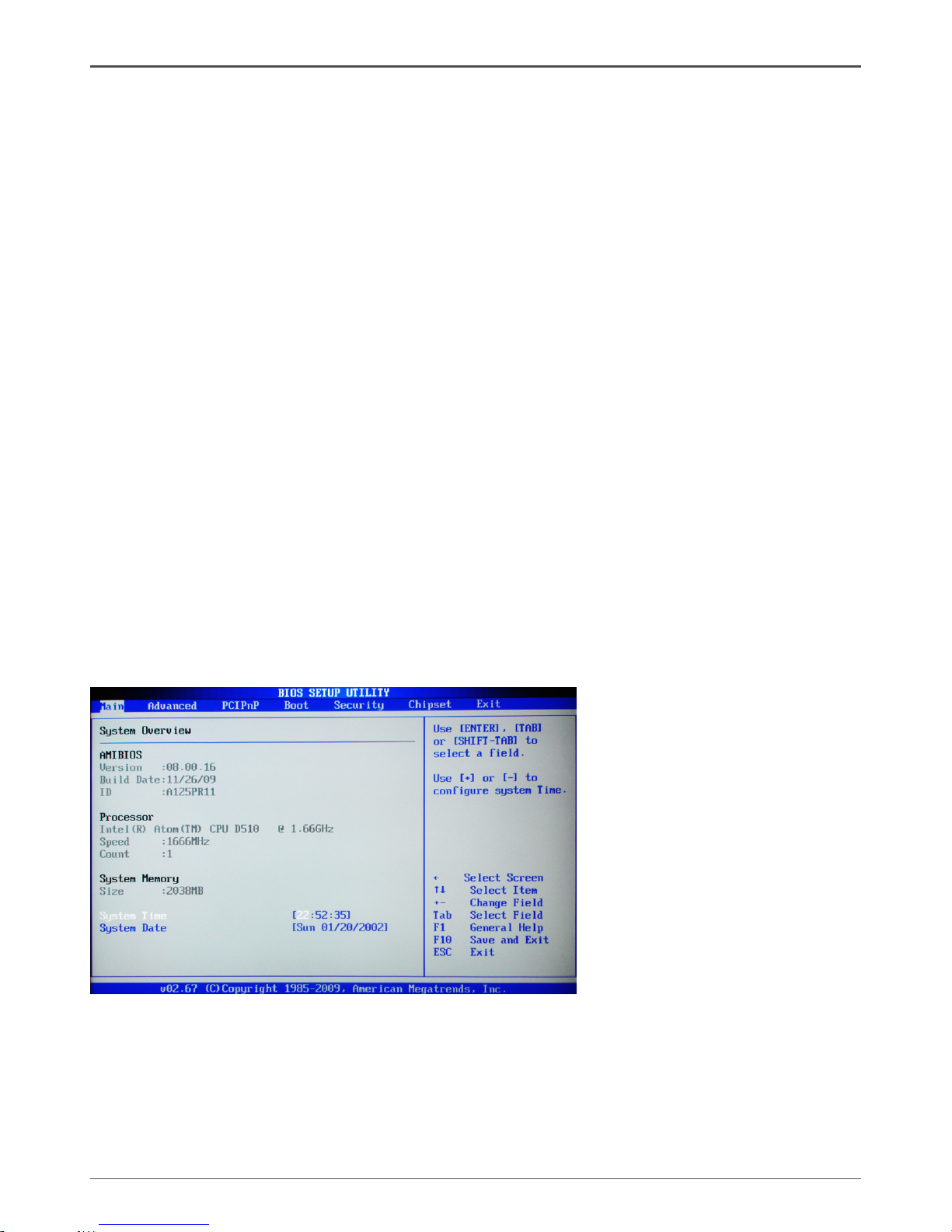
Expansion slots
The motherboard contains three expansion slots, two Mini PCIE slots and one PCIE x1 slot.
Mini PCIE Slots-MINI_PCIE1/2
There are two Mini PCIE slots, reserved for the WiFi Module.
PCIE x1 Slot-PCIEX1
There is one PCI Express x1 slot that is designed to accommodate less bandwidth intensive
cards, such as a modem or LAN card. The PCI Express x1 slot provides 500 MB/s bandwidth.
120
240
121
120
240
121
Hardware Installation
Jumper Settings
This chapter explains how to congure the motherboard’s hardware. Before using your
computer, make sure all jumpers and DRAM modules are set correctly. Refer to this section
whenever in doubt.
CMOS Clear Jumper-JP1
Close Open * = Default setting.
If you want to clear the system conguration, use the JP1 (Clear CMOS Jumper) to clear data.
Notice:
1. Be sure to save the CMOS setting when exit the CMOS.
2. If the CPU is frequency multiplier locked, no CPU speed change will be seen even if the
frequency multiplier setting in CMOS setup is changed.
JP1 Selection
1-2* Normal*
2-3 CMOS Clear
1
1
1 51
2 52
M_PCIE2
PCIEX1
1
51
2
52
M_PCIE1
Page 19
18
Intel® NM10-ITX series Motherboard
Conguring the BIOS
This section discusses how to change the system settings through the BIOS Setup
menus. Detailed descriptions of the BIOS parameters are also provided.
Enter BIOS Setup
The BIOS is the communication bridge between hardware and software. Correctly
setting the BIOS parameters is critical to maintain optimal system performance.
Use the following procedure to verify/change BIOS settings.
1. Power on the computer.,
2. Press the Del key when the following message briey displays at the bottom of
the screen during the Power On Self Test (POST).
Pressing Del takes you to the BIOS Setup Utility.
Note: 1. We reserve the right to update the BIOS version presented in the manual. The
BIOS pictures shown in this section are for reference only.
2. It is strongly recommended that you do not change the default BIOS settings.
Changing some settings could damage your system.
Main Menu
This menu gives you an overview of the general system specications. The BIOS
automatically detects the items in this menu.
Note: Users please note
that the data in gray is nonchangeable, and the others
are for selection.
q AMI BIOS
Displays the auto-detected BIOS information
q Processor
Display the auto-detected CPU specication
q System Memory
Displays the auto-detected system memory
q System time
Allows you to set the system time
Page 20
19
Conguring the BIOS
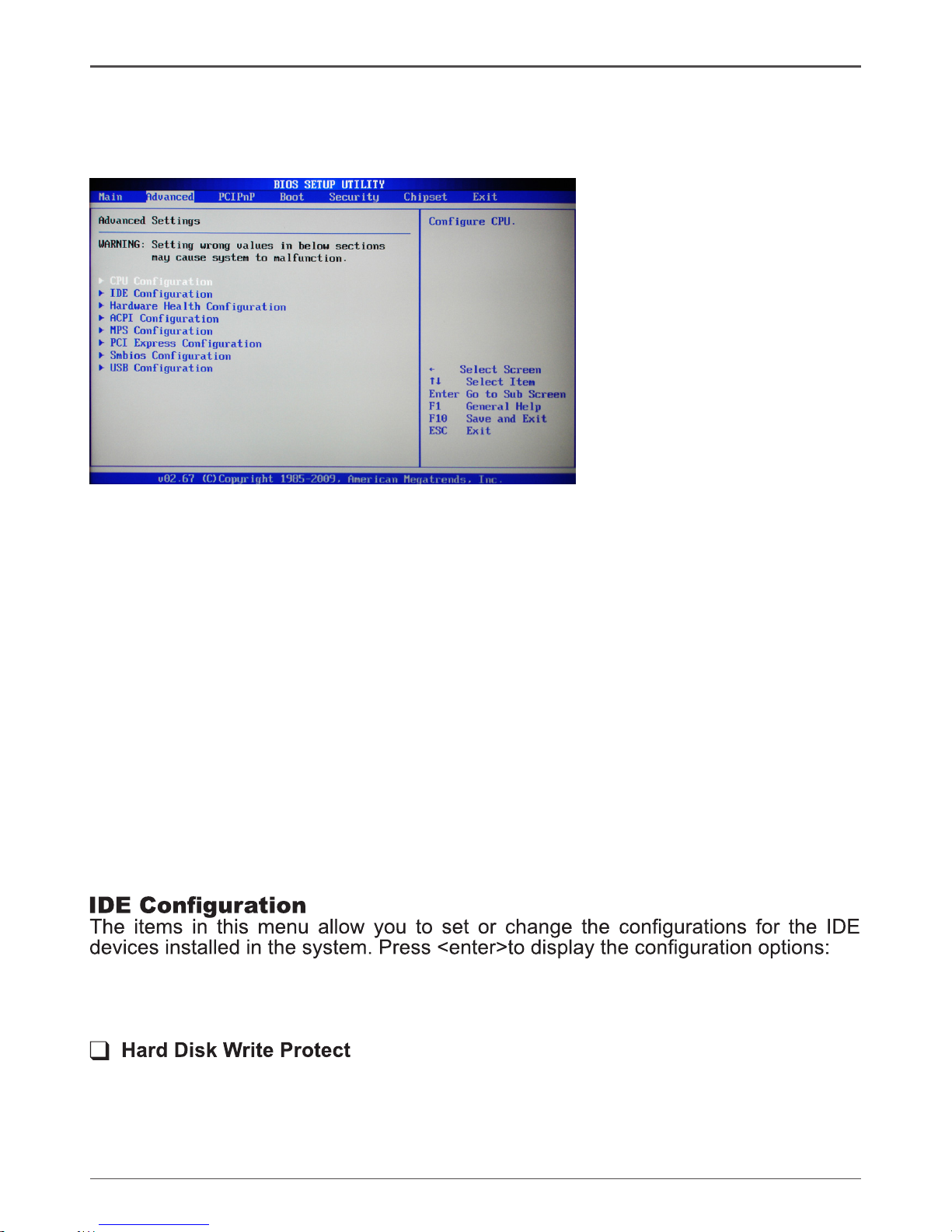
Advanced Menu
The Advanced menu items allow you to change the settings for the CPU and other
system devices. Press <enter> to display the conguration options:
CPU Conguration
The items in this menu show the CPU-related information that the BIOS automatically
detects. Press <enter>to display the conguration options:
q Congure advanced CPU settings
Displays the auto-detected CPU information
q Max CPUID Value Limit
Allows you to determine whether to limit CPUID maximum value. Set this item
to [Disable] Windows XP operating system; set this item to [Enable] for legacy
operating system such as Windows NT4.0..
q Execute-Disable Bit Capability
This function enhances protection of your computer , reducing exposure to viruses
and malicious buffer overow attacks when working with its supporting software
and system.
q Hyper Threading Technology
Enable this function for Windows and Linux4 OS, (OS supports Hyper Threading
Technology)
Disable this function for other OS. (OS not optimized for Hyper Threading
Technology)
q Congure SATA as
This item allows you to congure SATA as IDE/AHCI/Disabled mode.
q SATA Run Mode Conguration
This item allows you to congure the SATA run mode.
This item will be effective only if the device is accessed through BIOS.
q IDE Detect Time Out (Sec)
The item allows you to select the time out value for detecting ATA/ATAPI devices.
q ATA (PI) 80pin Cable detection
The item allows you to select the mechanism for detecting 80pin ATA(PI) cable.
Page 21

20
Intel® NM10-ITX series Motherboard
Hardware Health Conguration
This menu gives you an overview of the Hardware Health Conguration, including
System Temperature, CPU Temperature, and etc..
ACPI Conguration
The items in this menu allow you to set General ACPI conguration, Advanced ACPI
Conguration and Chipset ACPI Conguration.
MPS Conguration
The items in this menu allow you to congure MPS.
PCI Express Conguration
The items in this menu allow you to enable or disable PCI Express L0S and L1 link
power states.
Smbios Conguration
SMBIOS SMI wrapper support for PnP Function 50h-54h.
USB Conguration
The items in this menu allow you to change the USB-related features. Press <enter>
To display the conguration options:
q Legacy USB Support
Allows you to enable or disable support for USB devices on legacy operating
systems.
q USB 2.0 Controller Mode
Allows you to congure the USB 2.0 controller in HiSpeed or Full Speed .
q BIOS EHCI Hand-Off
Allows you to enable support for operating systems without an EHCI hand-off
feature.
q Legacy USB1.1 HC Support
Allows you to enable or disable Legacy USB1.1 HC support.
Page 22
21
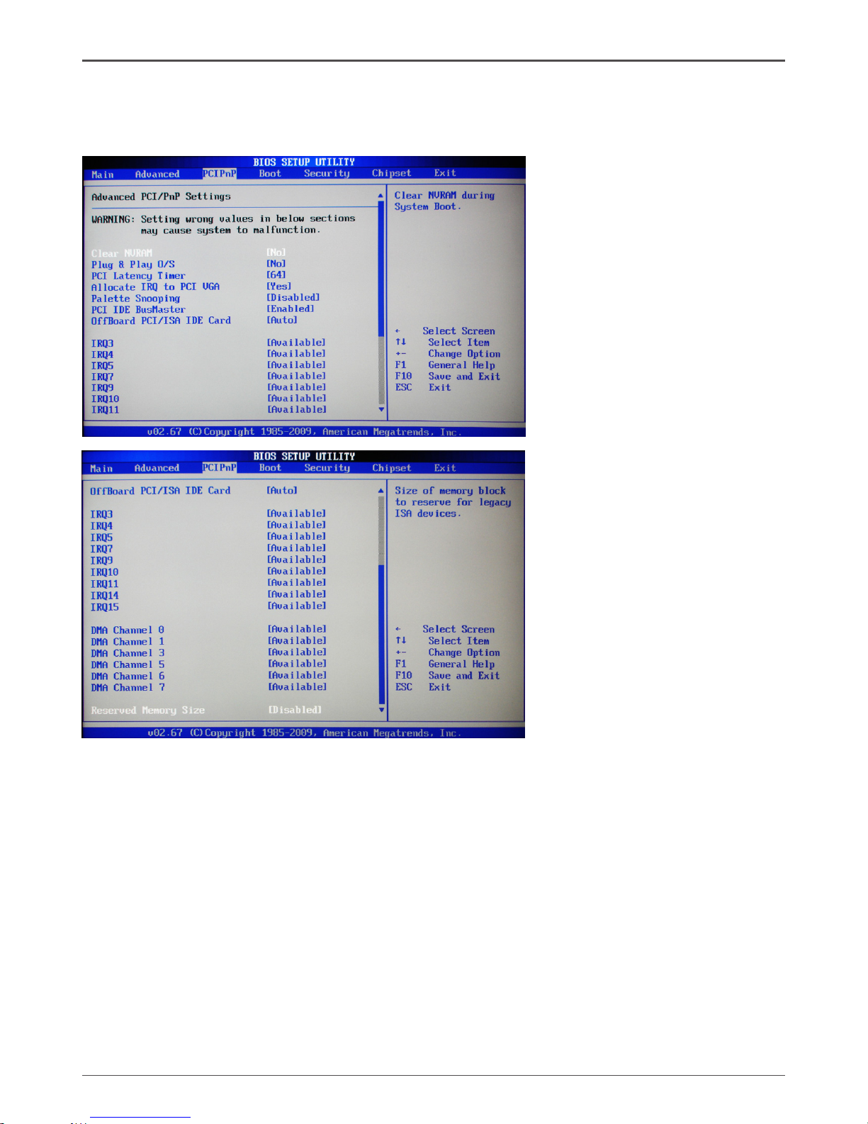
PCIPnP Menu
The PCIPnP menu shows the congurations of PCI bus system and PnP features.
Press <enter> to display the conguration options:
Caution: Since wrong
settings may cause
system to malfunction,
it is not recommended
for nonprofessionals to
change the settings of the
PCIPnP menu.
q Clear NVRAM
The item allows you to select whether clear NVRAM during system boot.
q Plug and Play O/S
When set to [No], BIOS congure all the devices in the system. When set to
[YES] and if you install a Plug and Play operating system, the operating system
congures the Plug and Play devices not required for boot.
q PCI Latency Timer
Allows you to select the value in units of PCI clocks for PCI device latency timer
register.
q Allocate IRQ to PCI VGA
When set to [YES], BIOS assigns an IRQ to PCI VGA card if the requests for an
IRQ. When set to [No], BIOS does not assign an IRQ to the PCI VGA card even
if requested .
q Palette Snooping
When set to [Enabled], the pallete snooping feature informs the PCI devices that
an ISA graphics device is installed in the system so that the latter can function
correctly.
Conguring the BIOS
Page 23
22
Intel® NM10-ITX series Motherboard
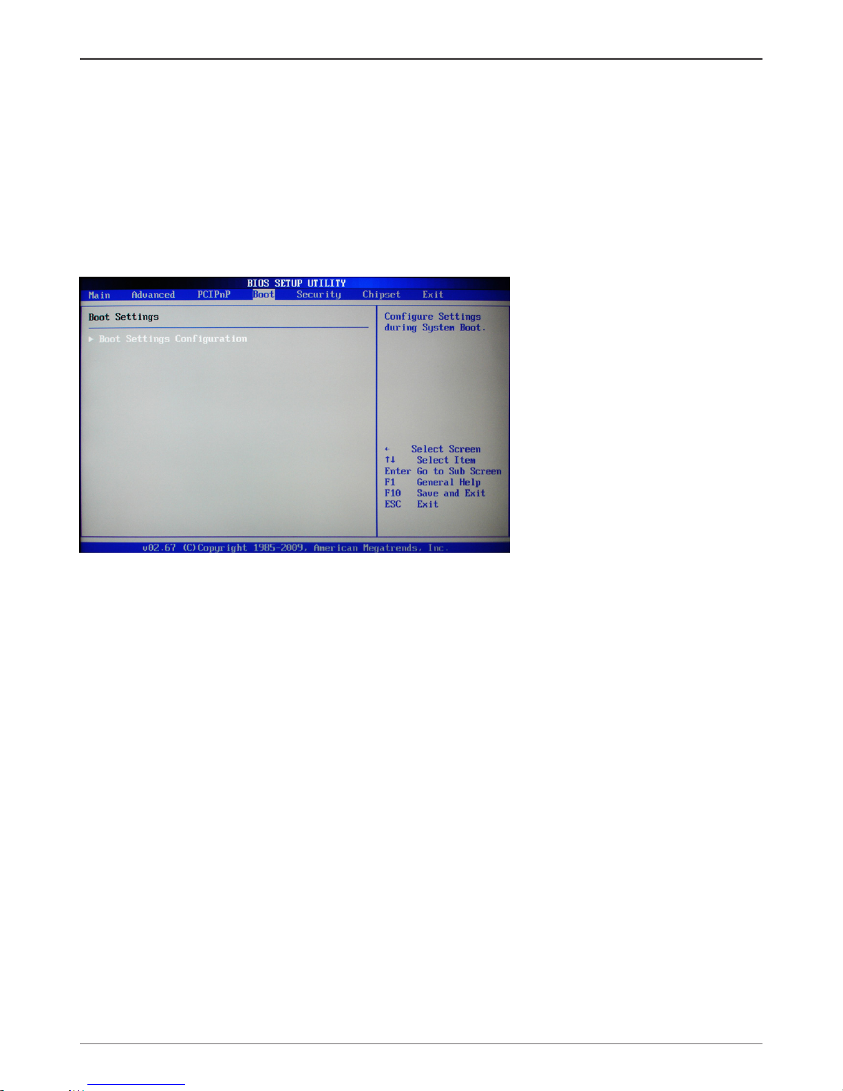
Boot Menu
The Boot menu items allow you to change the system boot options. Press <enter> to
display the conguration options:
Boot Settings Conguration
The items allow you to congure Boot settings. Press <enter> To display the
conguration options:
q Quick Boot
Enabling this item allows the BIOS to skip some power on self tests while booting
to decrease the time needed to boot the system. When set to [Disabled], BIOS
performs all the POST items.
q Quiet Boot
When set to [Disabled], displays normal POST message. When set to [Enabled],
displays OEM Logo instead of POST messages.
q AddOn ROM Display Mode
Sets the display mode for option ROM.
q Bootup Num-Lock
Allows you to select the power-on state for the NumLock.
q PS/2 Mouse Support
This item allows you to enable or disable support for PS/2 mouse.
q Wait for ‘F1’ If Error
When set to [Enabled], the system waits for the F1 key to be pressed when error
occurs.
q Hit ‘DEL’ Message Display
When set to [Enabled], the system displays the message “press DEL to run setup”
during POST.
q Interrupt 19 Capture
When set to [Enabled], this function allows the option ROMS to trap interrupt 19.
q PCI IDE BusMaster
When set to [Enabled], BIOS use PCI busmastering for reading /writing to IDE
drives.
q OffBoard PCI/ISA IDE Card
Use this option to set the PCI slot number for some PCI IDE Cards holding.
Page 24
23
Conguring the BIOS
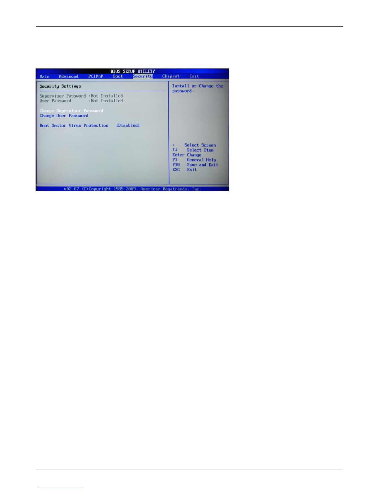
Security Menu
The security menu items allow you to change the system security settings. Press
<enter> to display the conguration options:
Change Supervisor/User Password
Select this item to set or change the supervisor/user password. The Supervisor/User
Password item on top of the screen shows the default setting: [Not Installed]. After you
set a password, this item shows [Installed].
To set a Supervisor/User Password:
1. Select the item [Change Supervisor/User Password] and press <Enter>.
2. From the password box, type a password composed of at least six letters and/or
numbers, then press <Enter>.
3. Conrm the password when prompted:
The message “Password Installed” appears after you successfully set your
password.
To change the supervisor/user password, follow the same steps as setting a use
password.
To clear the supervisor/user password, select the item [Change Supervisor/User
password], then press <enter>. The message “Password Uninstalled” appears.
Boot Sector Virus Protection
The items allow you to enable or disable booting sector virus protection.
Page 25
24
Intel® NM10-ITX series Motherboard
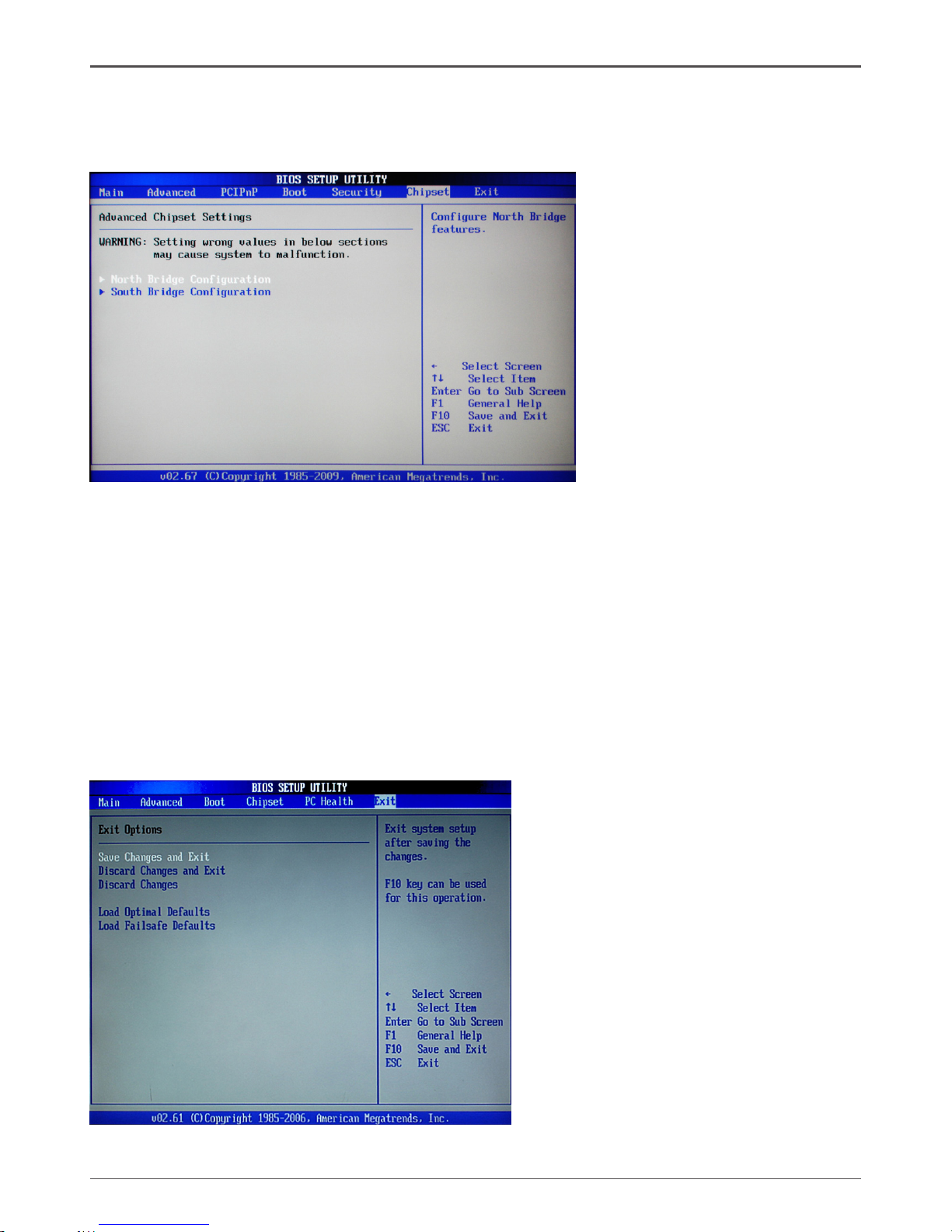
Chipset Menu
The chipset menu items allow you to change the advanced chipset settings. Press
<enter> to display the sub-menu:
NorthBridge Conguration
The items allow you to congure north bridge features, including Memory, Graphic,
Video, and so on.
SouthBridge Conguration
The items allow you to congure south bridge features, including USB, HDA, Onboard
Lan, and so on.
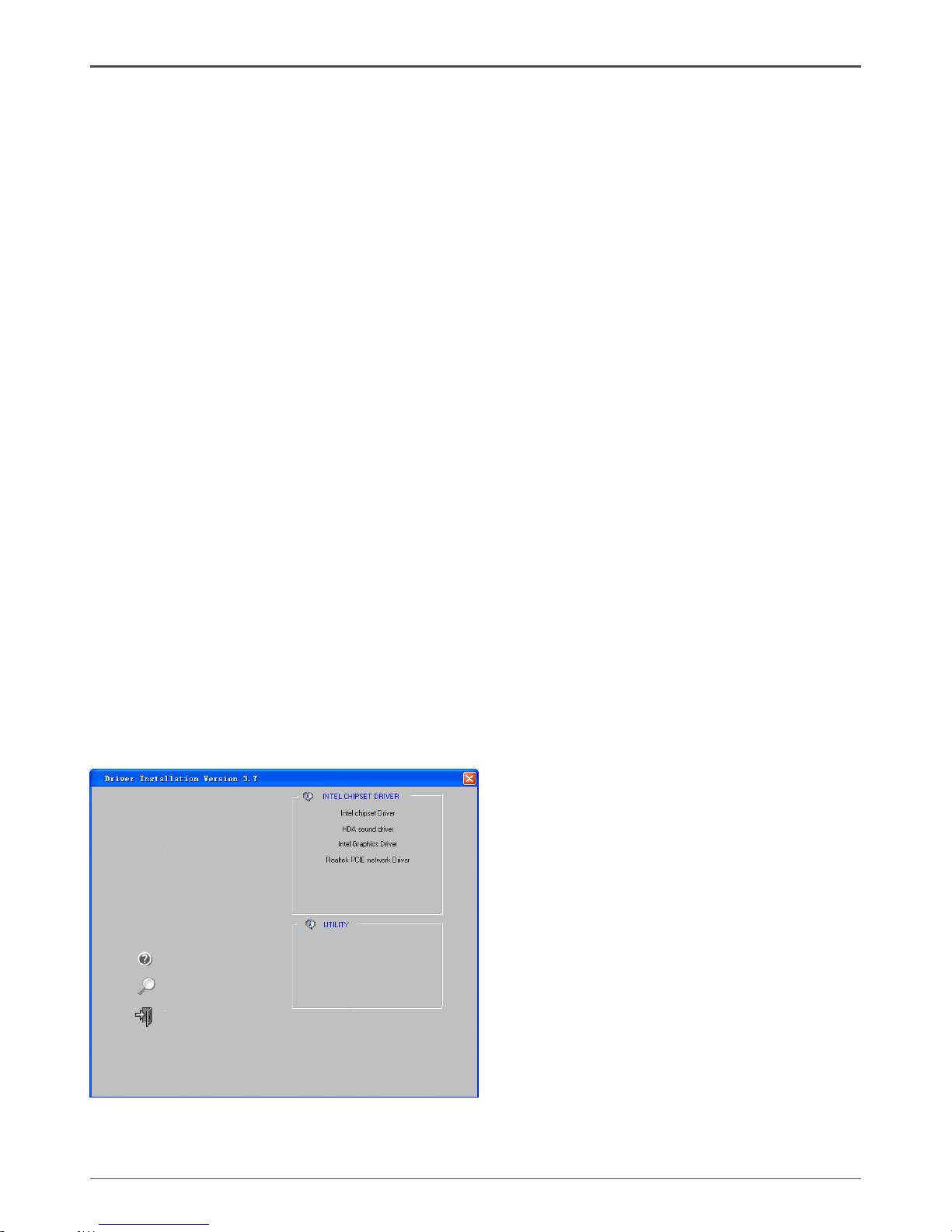
Exit Menu
The exit menu items allow you to load the option or failsafe default values for the BIOS
items, and save or discard your changes to the BIOS items. Press <enter> to display
the sub-menu:
Page 26

25
Save Changes and Exit
Select this item and press <Enter> to save the changes that you have made in the
BIOS Setup and exit the BIOS Setup. When the diolog box [Save conguration
changes and exit setup?] appears, select [Ok] to save and exit, or select [Cancel] to
return to the main menu.
Discard Changes and Exit
Select this option only if you do not want to save the changes that you made to the
setup program. If you made changes to elds other than system date, system time,
and password, the BIOS asks for a conrmation before exiting.
Discard Changes
This option allows you to discard the selections you made and restore the previously
saved values. After selecting this option, a conrmation appears. Select [Ok] to discard any change and load the previously saved values.
Load Optimal Defaults
This option allows you to load the default values for each of the parameters on the
setup menus. When you select this option, a conrmation window appears. Select
[Ok] to load default values. Select [Cancel] to make other changes before saving the
values to the non-volatile RAM.
Load Failsafe Defaults
This option has been set by the manufacturer and represents settings which provide
the minimum requirements for your system to operate.
Conguring the BIOS
FLASH Update Procedure
The program AFUDOS XX.ROM is included on the driver CD (D:\Utility\AFUDOS XX.ROM). Please
follow the recommended procedure to update the ash BIOS, as listed below.
1. Create a DOS-bootable oppy diskette. Copy the new BIOS le (just obtained or downloaded)
and the utility program AFUDOS XX.ROM to the diskette.
2. Allow the PC system to boot from the DOS diskette.
3. At the DOS prompt, type
AFUDOS XX.ROM /P /C /B /N /X <ENTER>
Note: XX (the BIOS le name) can be dened by users.
4. Wait until the ash-update is complete.
5. Restart the PC.
Warning: - Do not turn off or RESET the computer during the ash process.
- If you are not sure how to upgrade the BIOS, please take your computer to an
Authorized Service Center and have a trained technician do the work for you.
Page 27
26
Intel® NM10-ITX series Motherboard
Installing Drivers and Software
Note: It is important to remember that before installing the driver CD that is shipped in the
kit, you need to load your operating system. The motherboard supports Windows
XP 32 bit/64 bit; Windows Vista 32 bit/64 bit and Windows 7 32bit/64bit.
The kit comes with a CD that contains utility drivers and additional INTEL software.
The CD that has been shipped with your Intel® NM10 motherboard contains the following
software and drivers:
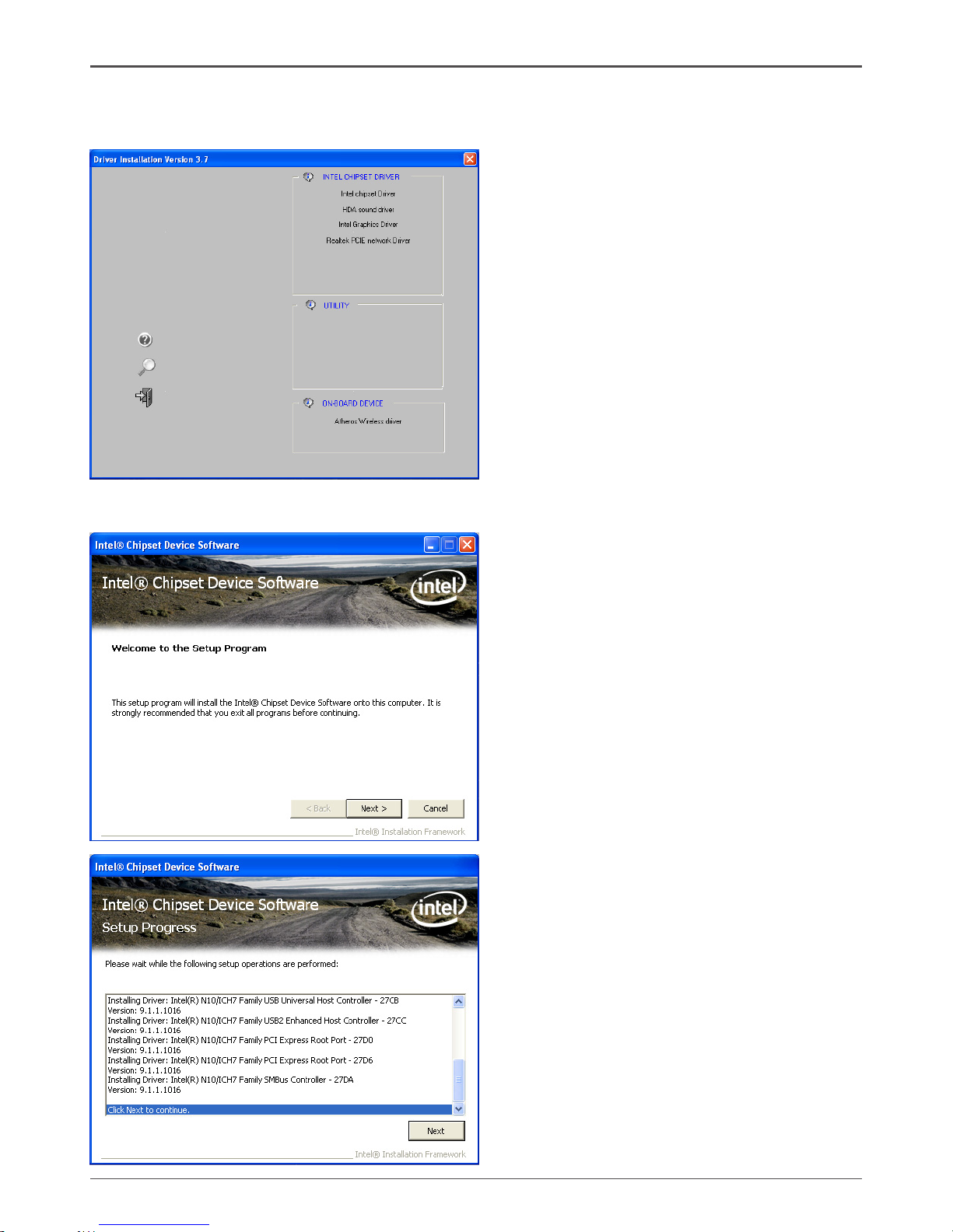
q Intel chipset Driver
q HDA sound driver
q Intel Graphics Driver
q Realtek PCIE network Driver
Note. We reserve the right to update the driver version presented in the manual. The driver
installation pictures shown in this section are for reference only.
Driver Installation
1. Insert the Intel® NM10 driver CD into the drive after loading your operating system, and then
you can see the interface below.
Page 28
27
Installing Drivers and Software
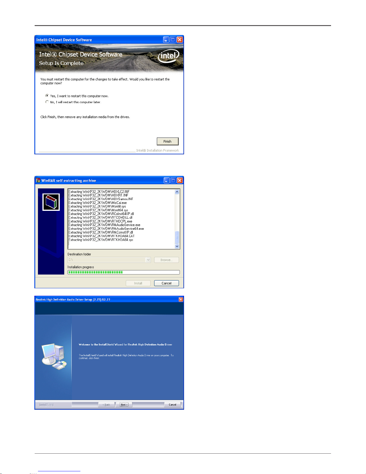
2. Left-click Intel chipset Driver, begin loading
Note. If the MINI PCIE card is installed, the option Atheros Wireless driver will display as
the following window.
Page 29
28
Intel® NM10-ITX series Motherboard
3. Left-click HDA sound driver, begin loading
Page 30
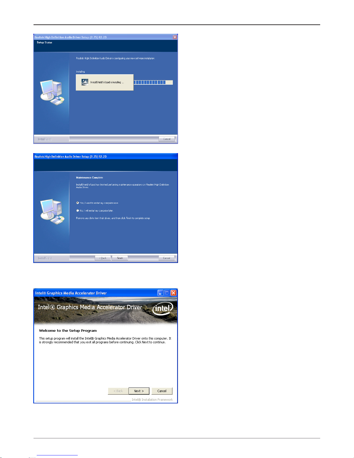
29
Installing Drivers and Software
4. Left-click Intel Graphics Driver, begin loading
Page 31
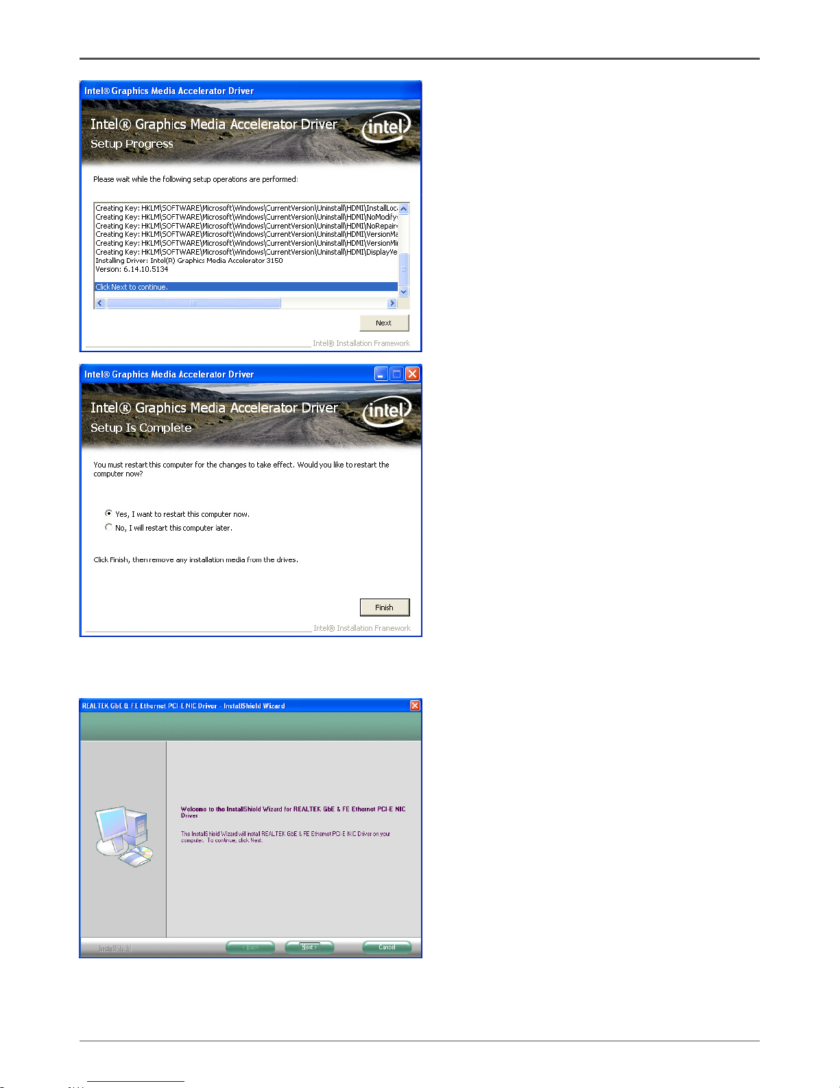
30
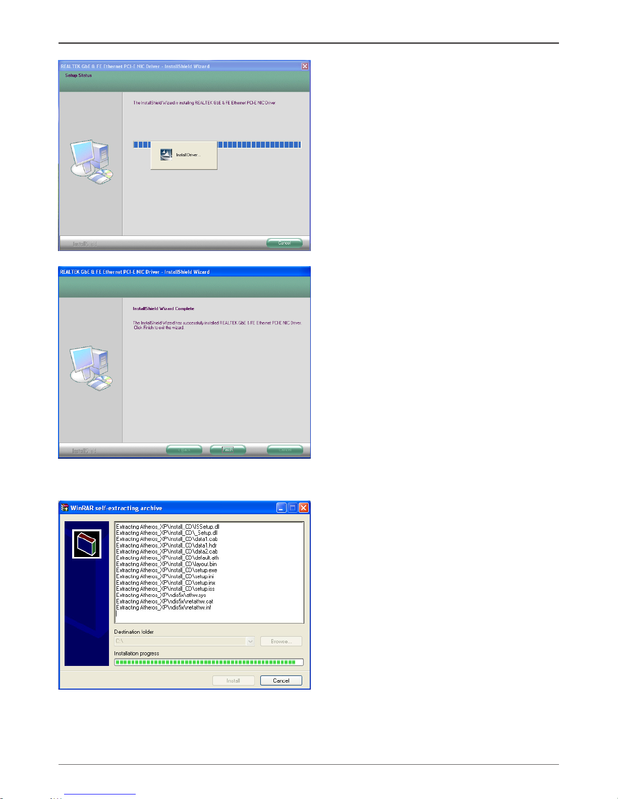
Intel® NM10-ITX series Motherboard
5. Left-click Realtek PCIE network Driver, begin loading
Page 32
31
Installing Drivers and Software
6. Left-click Atheros Wireless driver, begin loading
Page 33
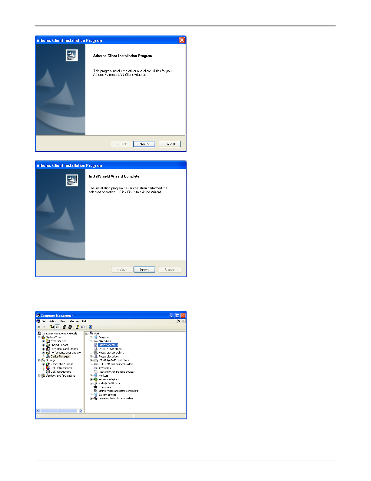
32
Intel® NM10-ITX series Motherboard
At last, you can enter Computer Management that provides information about the hardware
devices on this motherboard to check if the driver installation is complete.
Page 34
33
The adjustment of graghics properties
Thank you for choosing our NM10 series motherboard.
The product is specially designed to support HDMI/VGA dual display on Intel® ATOM
TM
+ NM10
platform, please read the following information and congure the system accordingly to enjoy
the unique feature.
Note: 1. Before adjusting the graphics properties, make sure that the graphics driver has
been installed completely.
2. The screenshots shown in this section are for the Windows® XP operating
system.
Users please note that the graghics properties can be adjusted as the following instructions.
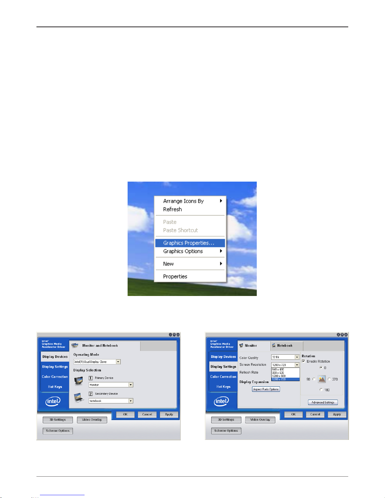
1. Right-click the mouse on the desktop, and choose Graphics Properties item.
An interface will display as the image below. Click Display Settings tab, you can see the
default Screen Resolution.
Installing Drivers and Software
Page 35
34
Intel® NM10-ITX series Motherboard
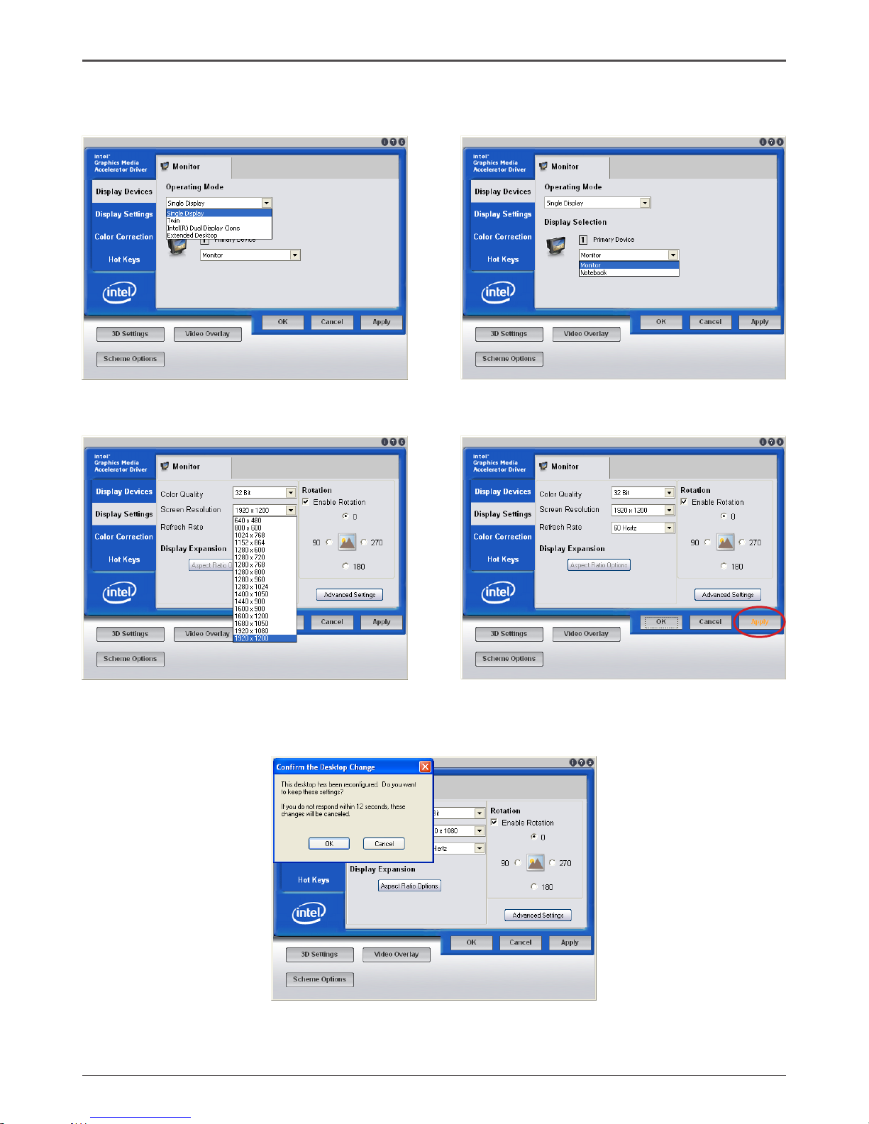
2. In Display Devices tab, set Operating Mode to Single Display, and set Primary
Device to Monitor.
3. Click Display Settings tab, choose the Screen Resolution you want, and click Apply.
4. The dialogue box will appear as the image below. If you conrm the desktop change,
please click OK. If you want to keep the settings, please click Cancel.
Page 36
35
Realtek HD Audio Driver Setup
Getting Started
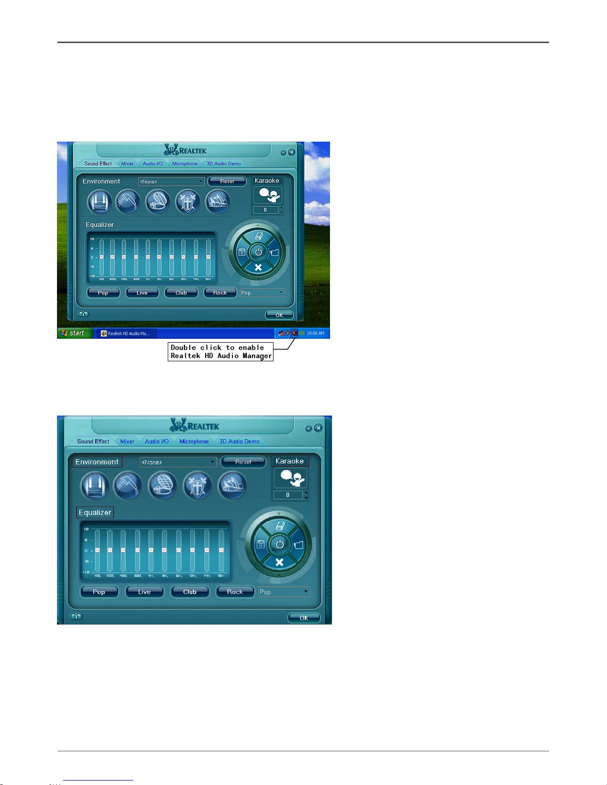
After Realtek HD Audio Driver being installed (insert the driverCD and follow the
on-screen instructions), “Realtek HD Audio Manager” icon will show in System tray
as below. Double click the icon and the control panel will appear:
Sound Effect
After clicking on the “Sound Effect” tab, 3 sections “Environment”, “Equalizer” and
“Karaoke” are available for selection.
Environment Simulation
You will be able to enjoy different sound experience by pulling down the arrow,
totally 23 kinds of sound effect will be shown for selection. Realtek HD Audio Sound
Manager also provides ve popular settings “Stone Corridor”, “Bathroom”, “Sewer
pipe”, “Arena” and “Audio Corridor” for quick enjoyment.
Installing Drivers and Software
Page 37
36
Intel® NM10-ITX series Motherboard
Equalizer Selection
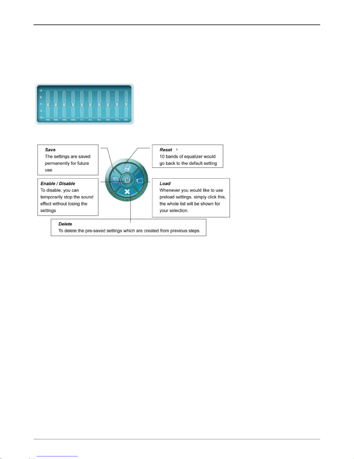
The Equalizer section allows you to create your own preferred settings by utilizing
this tool.
In standard 10 bands of equalizer, ranging from 100Hz to 16KHz are available:
Frequently Used Equalizer Setting
Realtek recognizes the needs that you might have. By leveraging our long
experience at audio eld, Realtek HD Audio Sound Manager provides you certain
optimized equalizer settings that are frequently used for your quick enjoyment.
How to Use
Other than the buttons “Pop” “Live” “Club” & “Rock” shown on the page, to pull down
the arrow in “Others” , you will nd more optimized settings available to you.
Karaoke Mode
Karaoke mode brings Karaoke fun back home by simply using the music you usually
play, Karaoke mode can help you eliminate the vocal of the song or adjust the key to
accommodate your range.
Vocal Cancellation: Single click on “Voice Cancellation”, the vocals of the songs
will be erased, while the background music is still playing which lets you take over
the vocal part.
Key Adjustment: Using “Up / Down Arrow” to nd a key which better ts your vocal
range.
Page 38
37
Installing Drivers and Software
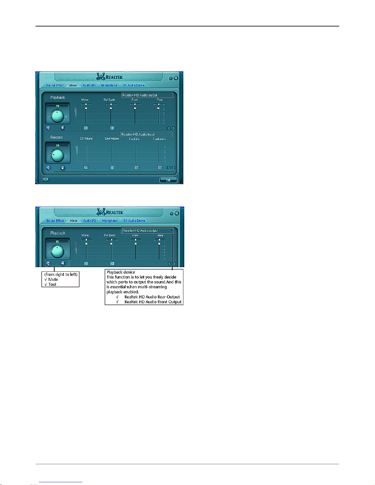
Mixer
Realtek HD Audio Sound Manager integrates Microsoft’s “Volume Control” functions
into the Mixer page. This gives you the advantage to you to create your favorite
sound effect in one single tool.
Playback control
Mute
You may choose to mute single or multiple volume controls or to completely mute
sound output.
Tool
√ Show the following volume control
This is to let you freely decide which volume control items to be displayed, total
13 items to be chosen.
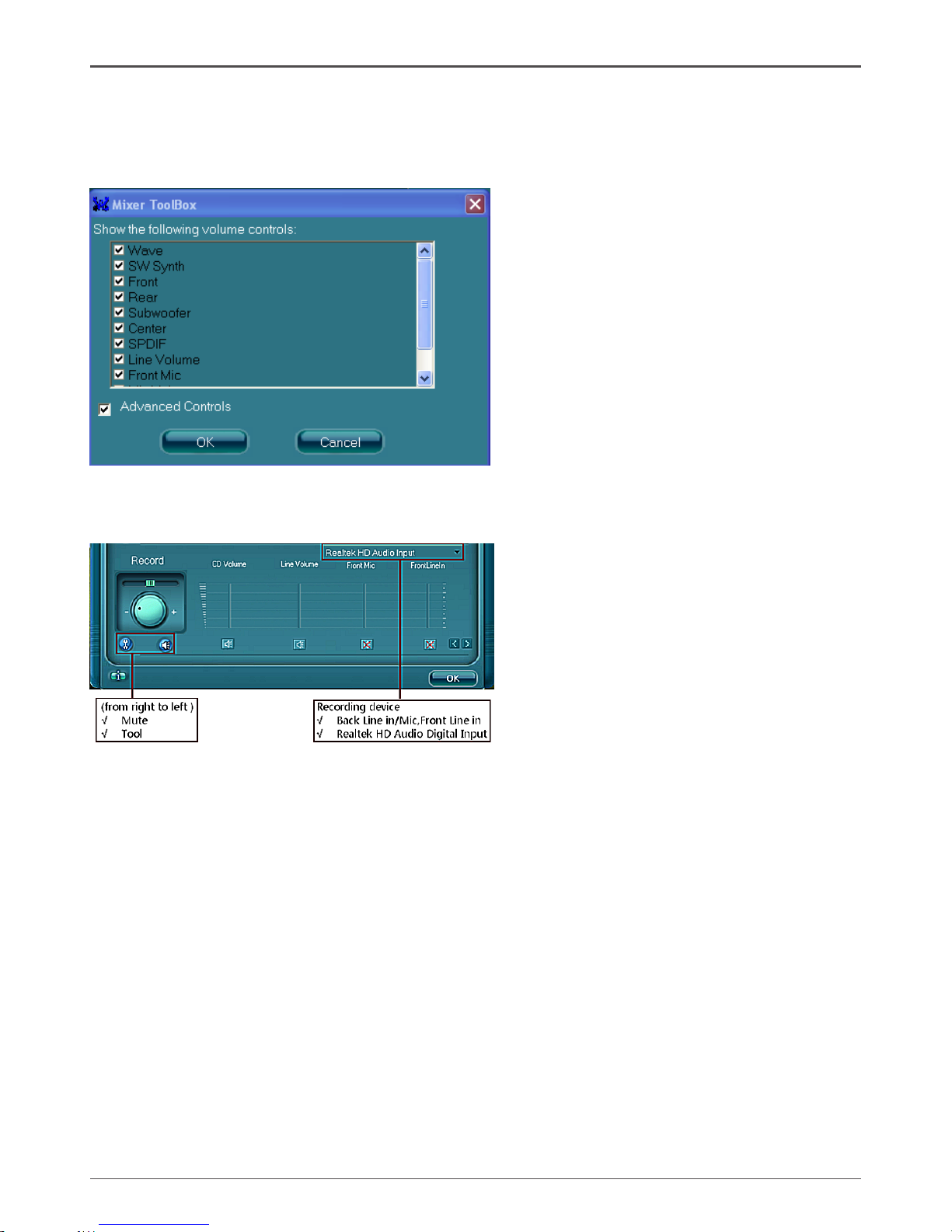
√ Advanced controls
√ Enable playback multi-streaming
Page 39
38
Intel® NM10-ITX series Motherboard
With this function, you will be able to have an audio chat with your friends via
headphone (stream 1 from front panel) while still have music (stream 2 from back
panel) playing. At any given period, you can have maximum 2 streams operating
simultaneously.
Recording control
Mute
You may choose to mute single or multiple volume controls or to completely mute
sound input.
Tool
√ Show the following volume controls
This is to let you freely decide which volume control items to be displayed.
√ Advanced controls.
Advanced control is a “Microphone Boost” icon.
Once this item is checked, you will nd “advanced” icon beside “Front Pink In” &
“Mic Volume”. With this, the input signal into “Front Pink In” & “Mic Volume” will
be strengthen.
√ Enable recording multi-streaming
At any given period, you can have maximum 2 streams operating simultaneously.
Page 40
39
Installing Drivers and Software
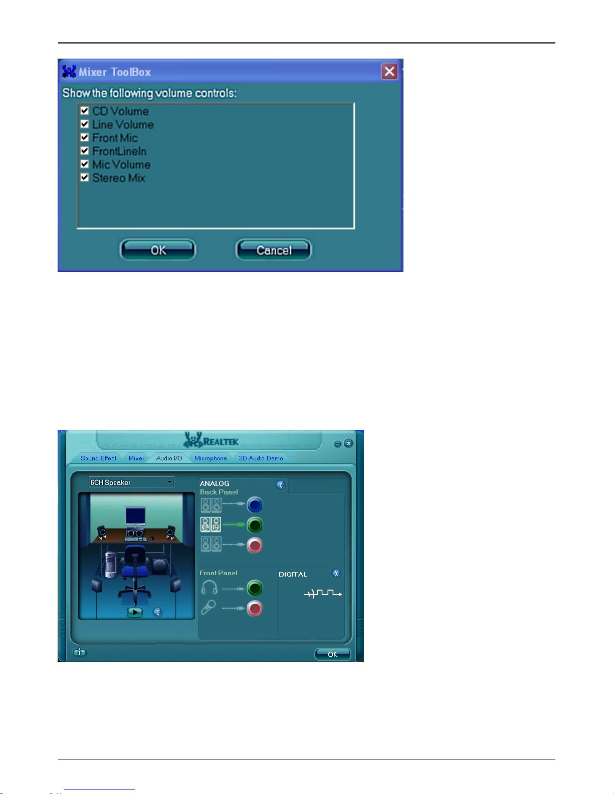
Audio I/O
Realtek HD Audio Manager frees you from default speaker settings. Different from
before, for each jack, they are not limited to perform certain functions. Instead, now
each jack is able to be chosen to perform either output (i.e. playback) function or
input (i.e. Recording) function, we call this “Retasking”.
Audio I/O aims to help you setting jacks as you wish. Moreover, other than blue to
blue, pink to pink, the way that you used to do, Audio I/O would guide you to other
right jacks that can also serve as microphone / speaker / headphone.
Page 41
40
Intel® NM10-ITX series Motherboard
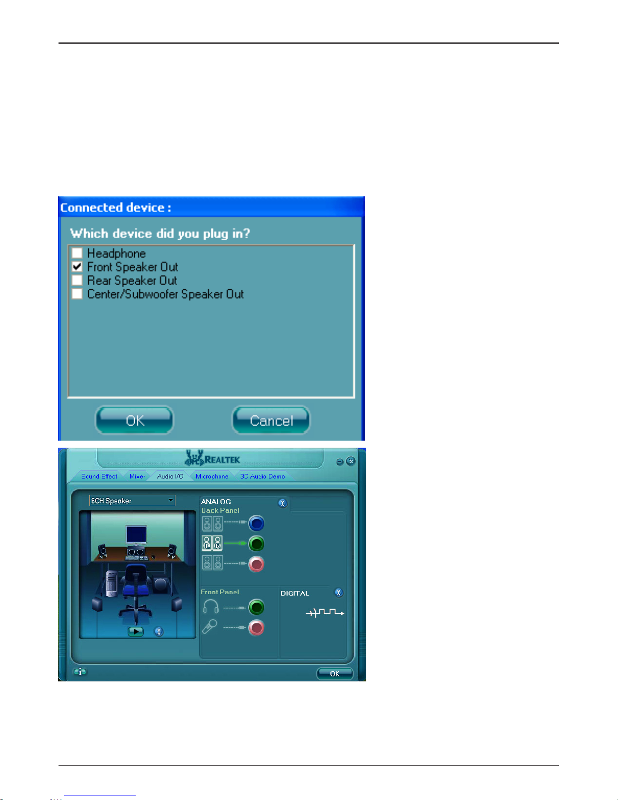
Speaker Conguration
Step 1: Plug in the device in any available jack.
Step 2:
Dialogue “connected device” will pop up for your selection. Please select the
device you are trying to plug in.
*
If the device is being plugged into the correct jack, you will be able to nd the
icon beside the jack changed to the one that is same as your device.
*
If not correct, Realtek HD Audio Manager will guide you to plug the device into
the correct jack.
Page 42
41
Installing Drivers and Software
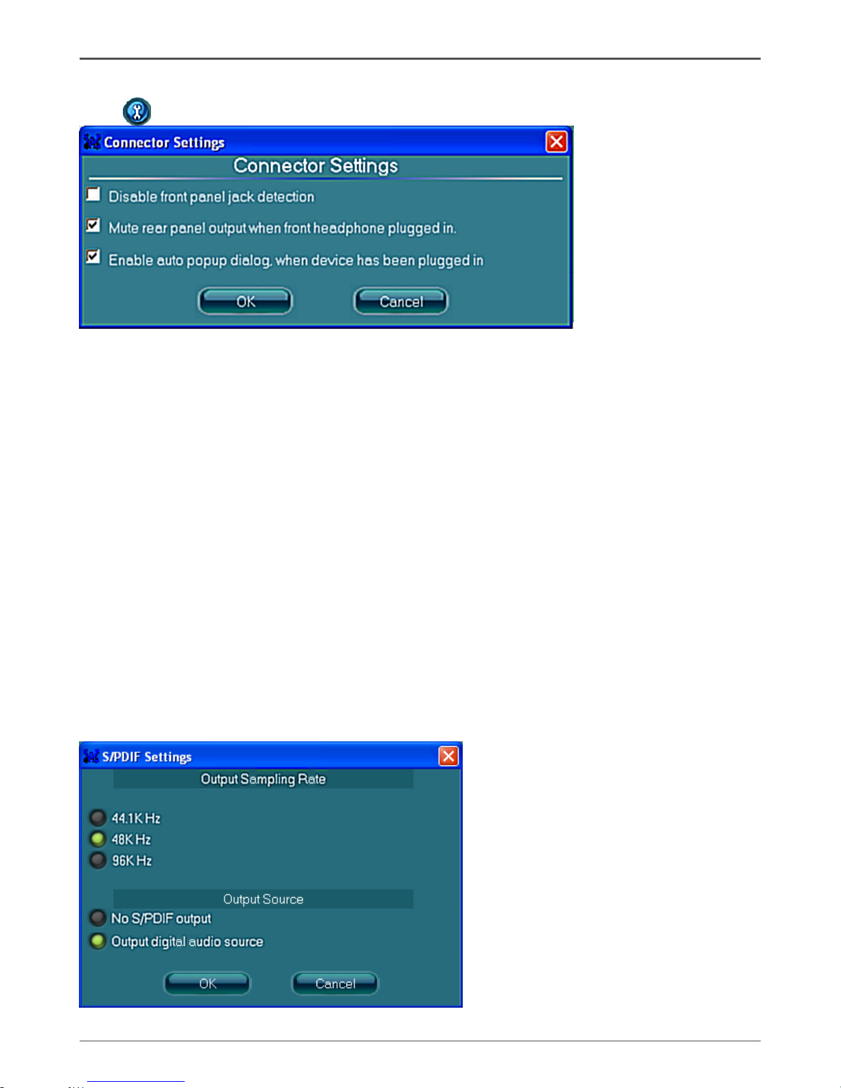
Connector Settings
Click to access connector settings
√ Mute rear panel when front headphone plugged in
Once this option is checked, when front headphone is plugged, the music that is
playing from the back panel, will be stopped.
√ Disable front panel jack detection (option)
Did not nd any function on front panel jacks?
Please check if front jacks on your system are so-called AC’97 jacks. If so,
please check this item to disable front panel jack detection.
√ Enable auto popup dialogue, when device has been plugged in.
Once this item checked, the dialog “Connected device” would automatically pop up
when device plugged in.
S/PDIF
Short for Sony/Philips Digital Interface, a standard audio le transfer format. S/PDIF
allows the transfer of digital audio signals from one device to another without having
to be converted rst to an analog format. Maintaining the viability of a digital signal
prevents the quality of the signal from degrading when it is converted to analog.
Page 43
42
Intel® NM10-ITX series Motherboard
√ Output Sampling Rate
- 44.1KHz: This is recommended while playing CD
- 48KHz: This is recommended while playing DVD or Dolby.
- 96KHz: This is recommended while playing DVD-Audio.
√ Output Source
- Output digital audio source: The digital audio format (such as .wav, .mp3,
.midi, and etc.) will come out through S/PDIF-Out.
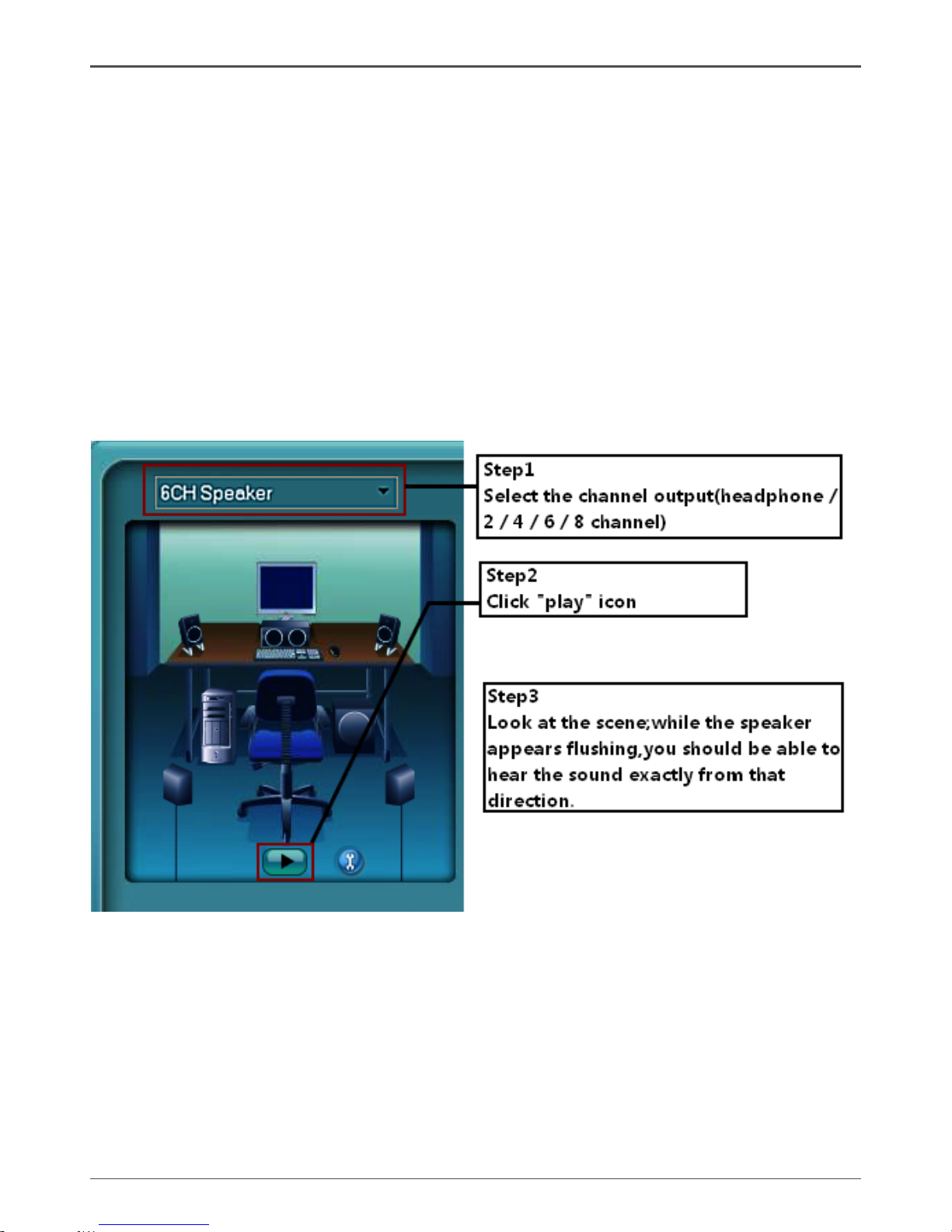
Speaker Calibration
After you have successfully plugged in speakers and assigned to the right jacks,
you are only one more step to go to enjoy the intended sound. We provide “Speaker
Calibration” to help you check if the speakers are located in the correct position.
Page 44
43
Installing Drivers and Software
Microphone
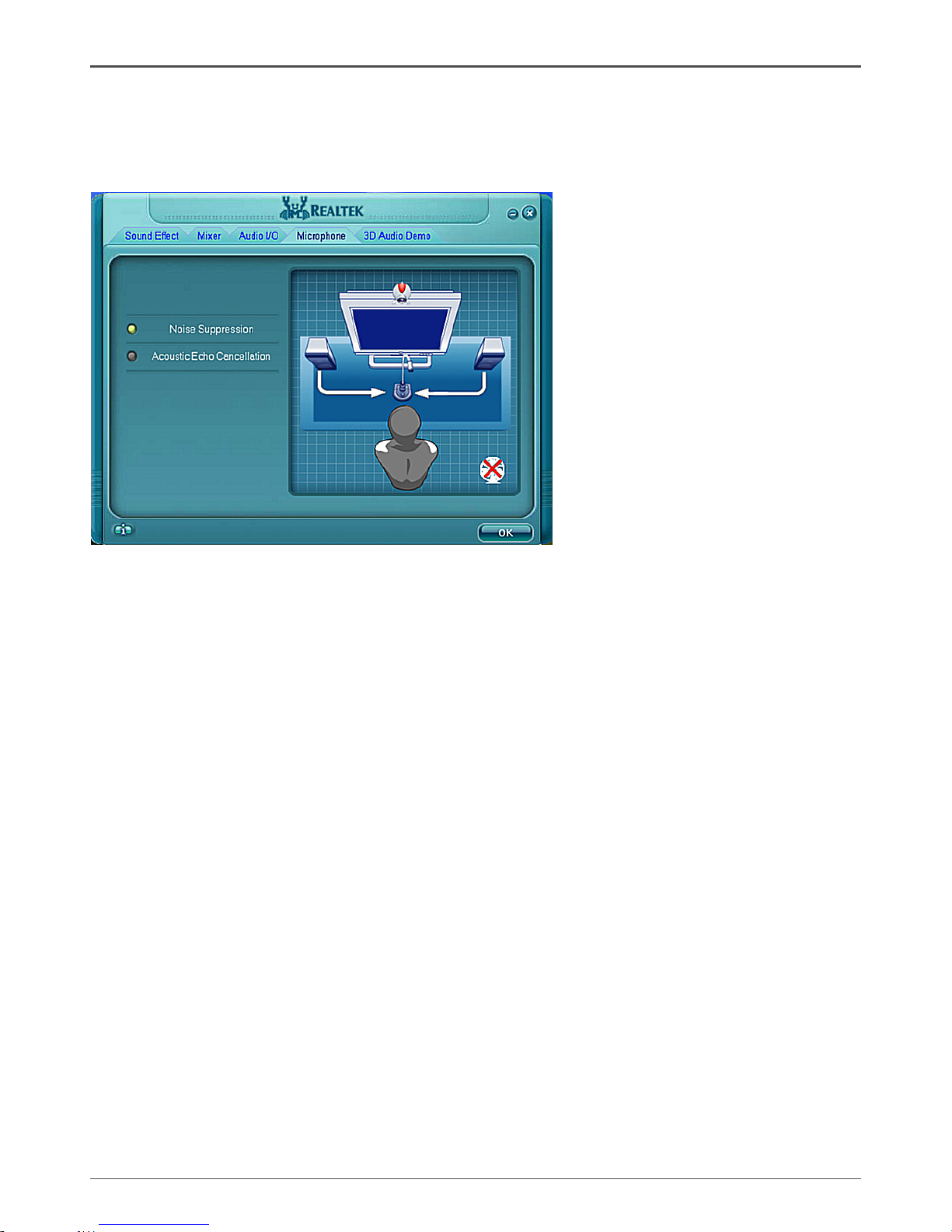
This page is designed to provide you better microphone / recording quality.
Below picture indicates both “Noise Suppression” & “Acoustic Echo Cancellation”
are both enabled.
Noise Suppression
If you feel that the background noise, especially the sound generated from the fan
inside PC, is too loud? Try “Noise Suppression”, which allows you to cut off and
suppress disturbing noise.
Beam Forming
Also known as “directional recording”, this option lets you do the following: Once
beam forming is enabled; only the sound from certain direction will be recorded. You
will get the best quality if you chose 90° position, which we recommend you to use,
this effectively means that you speak right into the microphone.
Note: A Stereo Microphone is required when using Beam Forming function.
Acoustic Echo Cancellation
This function prevents playback sound from being recorded by microphone together
with your sound. For example, you might have chance to use VOIP function through
Internet with your friends. The voice of your friend will come out from speakers
(playback). However, the voice of your friend might also be recorded into your
microphone then go back to your friend through Internet. In that case, your friend
will hear his/her own voice again. With AEC (Acoustic Echo Cancellation) enabled at
your side, your friend can enjoy the benet with less echo.
Page 45
44
Intel® NM10-ITX series Motherboard
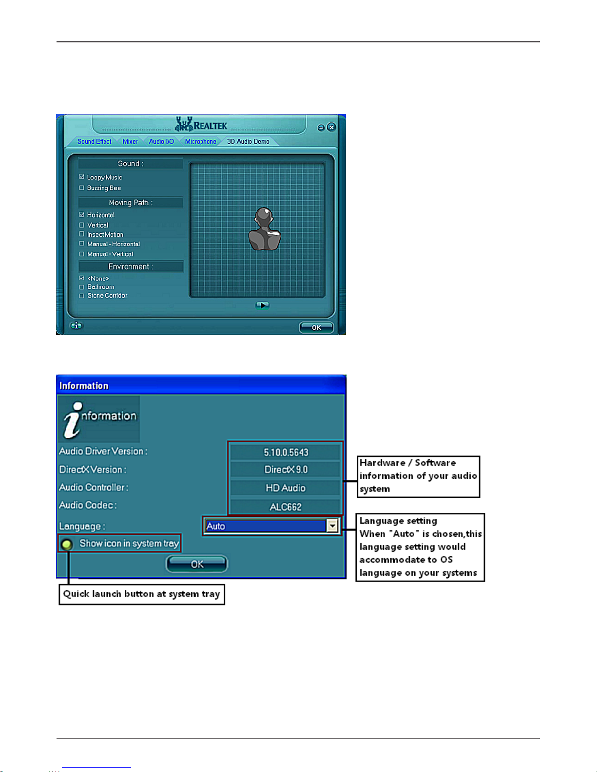
This section provides information about your current system audio device.
Information
Audio Demo
The section “3D Audio Demo” grants you another possibility to enjoy your sound.
The Audio Demo allows you to listen to sound in an extraordinary way.
291-MA125-01
Page 46

 Loading...