

Zotac NM10-DTX WiFi, NM10-DTX-B WiFi, NM10-DTX-D WiFi User Manual

1
Federal Communications Commission (FCC) Statement
This equipment has been tested and found to comply with the limits for a Class B digital device,
pursuant to Part 15 of FCC Rules. These limits are designed to provide reasonable protection
against harmful interference in a residential installation. This equipment generates, uses and
can radiate radio frequency energy and, if not installed and used in accordance with instructions
contained in this manual, may cause harmful interference to radio and television communications.
However, there is no guarantee that interference will not occur in a particular installation.
If this equipment does cause harmful interference to radio or television reception, which can
be determined by turning the equipment off and on, the user is encouraged to try to correct the
interference by one or more of the following measures:
- REORIENT OR RELOCATE THE RECEIVING ANTENNA
- INCREASE THE SEPARATION BETWEEN THE EQUIPMENT AND THE RECEIVER
- CONNECT THE EQUIPMENT INTO AN OUTLET ON A CIRCUIT DIFFERENT FROM
THAT OF THE RECEIVER
- CONSULT THE DEALER OR AN EXPERIENCED AUDIO/TELEVISION TECHNICIAN
NOTE:
Connecting this device to peripheral devices that do not comply with Class B requirements, or
using an unshielded peripheral data cable, could also result in harmful interference to radio or
television reception.
The user is cautioned that any changes or modications not expressly approved by the party
responsible for compliance could void the user’s authority to operate this equipment.
To ensure that the use of this product does not contribute to interference, it is necessary to use
shielded I/O cables.
Copyright
This manual is copyrighted with all rights reserved. No portion of this manual may be copied or
reproduced by any means.
While every precaution has been taken in the preparation of this manual, no responsibility for
errors or omissions is assumed. Neither is any liability assumed for damages resulting from the
use of the information contained herein.
Trademarks
All brand names, logos and registered trademarks mentioned are property of their respective
owners.
Electronic Emission Notices
WARNING!

2
Intel® NM10 series Motherboard
Table of Contents
Motherboard Specications ---------------------------------------------------------------------------------4
Motherboard Layout--------------------------------------------------------------------------------------------6
Hardware Installation ------------------------------------------------------------------------------------------ 9
Safety Instructions -------------------------------------------------------------------------------------------9
Installing Memory Modules --------------------------------------------------------------------------------10
Installing the Motherboard ---------------------------------------------------------------------------------11
Installing the I/O Shield ------------------------------------------------------------------------------------11
Securing the Motherboard into the Chassis ----------------------------------------------------------11
Connecting Cables and Setting Switches --------------------------------------------------------------12
24-pin ATX Power Connector-PW1 ---------------------------------------------------------------------13
4-pin ATX_12V power connector-PW2 ----------------------------------------------------------------- 13
SPDIF-Out Header-CN6 ----------------------------------------------------------------------------------- 14
COM Header-COM1 ---------------------------------------------------------------------------------------- 14
Front panel header-FP1 -----------------------------------------------------------------------------------14
USB Headers-FP_U1~FP_U2 --------------------------------------------------------------------------- 15
Front Pannel Audio Header-FP_S1 ---------------------------------------------------------------------15
Speaker Header-SPK1 -------------------------------------------------------------------------------------16
Fan Connectors ----------------------------------------------------------------------------------------------16
Serial-ATA (SATA) Connectors (SATA1~6) ------------------------------------------------------------16
Expansion Slots ---------------------------------------------------------------------------------------------- 17
Mini PCIE Slot -------------------------------------------------------------------------------------------- 17
PCIE x16 Slot --------------------------------------------------------------------------------------------17
PCIE x1 Slot ----------------------------------------------------------------------------------------------17
Jumper Settings ----------------------------------------------------------------------------------------------17
Conguring the BIOS ------------------------------------------------------------------------------------------18
Enter BIOS Setup -------------------------------------------------------------------------------------------------18
Main Menu -----------------------------------------------------------------------------------------------------18
Advanced Menu ----------------------------------------------------------------------------------------------19
USB Conguration --------------------------------------------------------------------------------------19
SuperIO Conguration ---------------------------------------------------------------------------------19
CPU Conguration --------------------------------------------------------------------------------------19
IDE Conguration ---------------------------------------------------------------------------------------20
Onboard RAID Controller Conguration -----------------------------------------------------------20
ACPI Conguration -------------------------------------------------------------------------------------20
Security ----------------------------------------------------------------------------------------------------20
Boot Menu -----------------------------------------------------------------------------------------------------21
Chipset Menu ------------------------------------------------------------------------------------------------- 22
PC Health Monitor Menu ----------------------------------------------------------------------------------22
Exit Menu ------------------------------------------------------------------------------------------------------23
Flash Update Procedure ---------------------------------------------------------------------------------- 24

3
Table of Contents
Installing Drivers and Software ---------------------------------------------------------------------------- 25
Driver Installation -----------------------------------------------------------------------------------------25
The adjustment of graphics properties ------------------------------------------------------------ 34
Realtek HD Audio Driver Setup ----------------------------------------------------------------------- 36
Getting Started -------------------------------------------------------------------------------------------36
Sound Effect ----------------------------------------------------------------------------------------------36
Environment Simulation ---------------------------------------------------------------------------36
Equalizer Selection ---------------------------------------------------------------------------------37
Frequently Used Equalizer Setting -------------------------------------------------------------37
Karaoke Mode ---------------------------------------------------------------------------------------37
Mixer -------------------------------------------------------------------------------------------------------- 38
Playback control ------------------------------------------------------------------------------------38
Recording control ---------------------------------------------------------------------------------- 39
Audio I/O --------------------------------------------------------------------------------------------------40
Speaker Conguration ---------------------------------------------------------------------------- 41
Connector Settings --------------------------------------------------------------------------------42
S/PDIF -----------------------------------------------------------------------------------------------42
Speaker Calibration ------------------------------------------------------------------------------- 43
Microphone -----------------------------------------------------------------------------------------------44
Noise Suppression ---------------------------------------------------------------------------------44
Beam Forming -------------------------------------------------------------------------------------- 44
Acoustic Echo Cancellation ----------------------------------------------------------------------44
Audio Demo ----------------------------------------------------------------------------------------------- 45
Information ------------------------------------------------------------------------------------------ 45
SATA RAID User Manual -------------------------------------------------------------------------------------46
JMicron HW RAID Manager -----------------------------------------------------------------------------46
Introduction of JMicron HW RAID Manager ------------------------------------------------------46
Creating JMicron HW RAID ---------------------------------------------------------------------------47
Deleting JMicron HW RAID ---------------------------------------------------------------------------50

4
Intel® NM10 series Motherboard
Motherboard Specications
q Chipset
v Intel® NM10 Family Express Chipset
q Size
v Mini-DTX form factor of 203X170mm
q Microprocessor support
v Integrated with Intel® AtomTM processor D4/D5 series featuring an integrated graphics core
(Intel® GMA 3150) with graphics performance improvements
v Supports Front Side Bus (FSB) Frequency of 667 MHz
q Operating systems
v Supports Windows XP 32 bit/64 bit, Windows Vista 32 bit/64 bit and Windows 7 32bit/64bit
q System Memory
v Supports single-channel DDR2 800/667 SDRAM
v Supports two unbuffered DIMMs
v Maximum memory size: 4 GB
q USB 2.0 ports
v Supports hot plug and play
v Ten USB 2.0 ports (six on the back panel, four via the USB brackets connected to the
internal USB headers)
v Supports USB 2.0 protocol up to 480 Mbps transmission rate
q Onboard Serial ATA
v Independent DMA operation on six ports (Optional)
v Data transfer rates of 3.0 Gb/s
v Supports SATA AHCI and RAID congurations
v Supports JMicron® HW RAID Manager
q eSATA Port
v One eSATA port on backpanel
v Supports hot plug and play
v Provide a link for 3.0 Gb/s data speed
q Onboard Lan
v Compliant to 802.3x ow control support
v 10/100/1000 IEEE 802.3 compliant
v Wake On LAN (WOL) power management support

5
Motherboard Specications
q Onboard High Denition Audio
v Supports 6-channel
v Supports Jack-Sensing function
v One SPDIF-out header on board
q Green Function
v Support SMM, APM, ACPI
v Suspend to DRAM supported (STR)
v RTC timer to power-on the system
v AC power failure recovery
q Graphics Processing Unit Features
v Integrated with Intel® GMA 3150
v Direct X9 compliant Pixel Shader v2.0
v 3D Graphics Rendering Enhancements
v HDMI port output support (resolution: 1280x720)
q PCI Express Interface
v Support PCI Express 1.0a
v Wake up function is supported
v Clock spread spectrum capability
q Expansion slots
v One MINI PCI express slot
v One PCI express X16 slot (corresponds to PCIE X1 lane)
v One PCI express X1 slot
6
Intel® NM10 series Motherboard
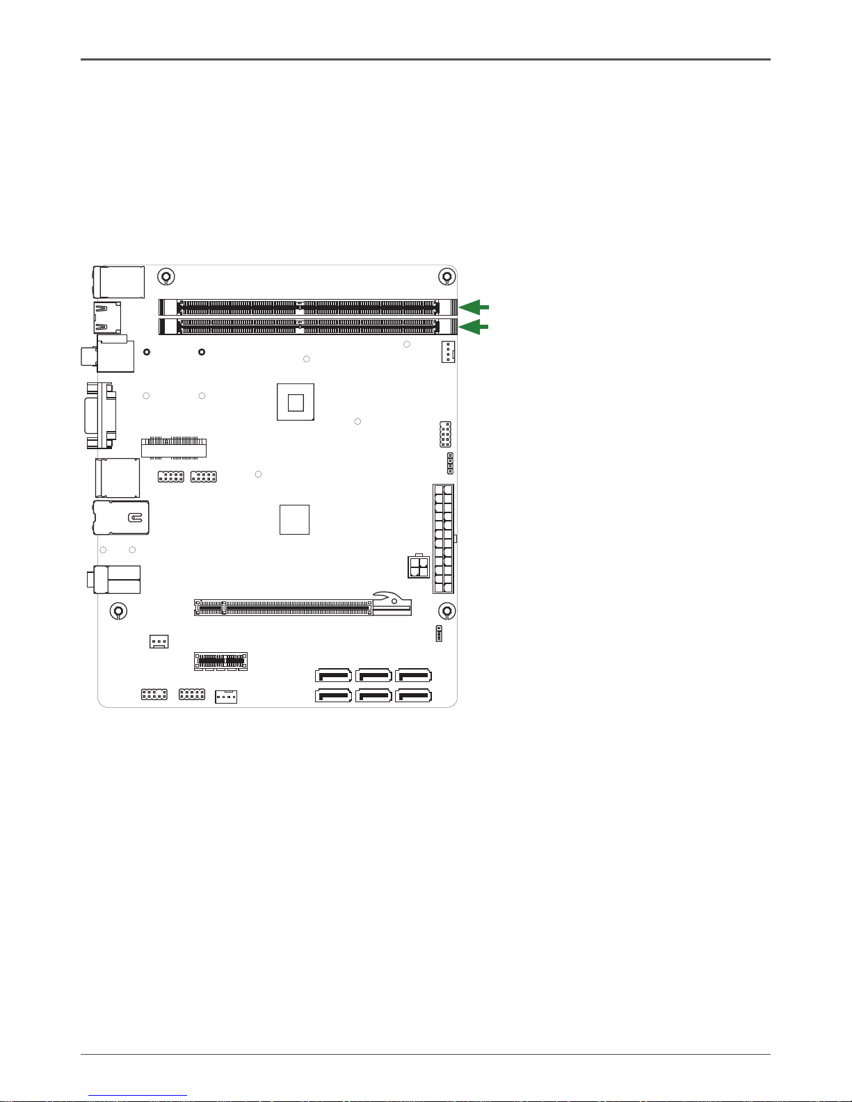
Motherboard Layout
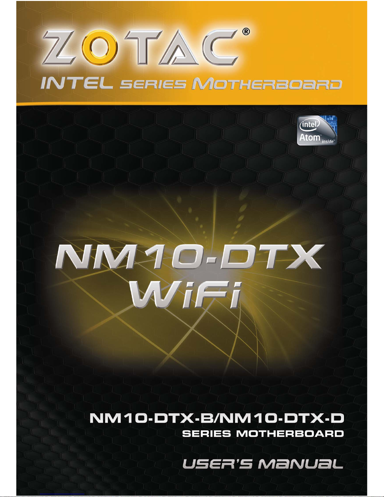
Figure 1 shows the motherboard and Figure 2 shows the back panel connectors.
Figure 1. Board Layout
1. DDRII DIMM Sockets-DDRII1~2
2. CPU Fan Connector-CPU_FAN
3. Front Panel Header-FP1
4. Speaker Header-SPK1
5. 24-pin ATX Power Connector-PW1
6. 4-pin ATX_12V power connector-PW2
7. Clear CMOS Jumper-JP1
8. Serial-ATA Connectors-SATA1~2 (for ordinary
SATA HDDs)
9. Serial-ATA Connectors-SATA3~6 (for creating
SATA RAID)
10. SYS Fan Connector-SYS_FAN
11. COM Header_COM1
12. Front pannel audio Header-FP_S1
13. PCI Express x1 Slot-PCIEX1
14. SPDIF-Out Header-CN6
15. PCI Express x 16 Slot-PCIE2
16. Backpanel connectors
17. Mini PCIE Slot-Mini_PCIEX1
18. USB Headers-FP_U1~FP_U2
19. Onboard CPU
20. Chipset
Figure 1
120
240
121
120
240
121
Chi pse t
DDR II- 1
DDR II- 2
PW1
SYS _FA N
FP1
SATA 1
SATA 2
PCI EX1
CPU FAN_
USB
JP1
PW2
HDM I
VGA
LA N USB/
SD1
KB
USB/
SPD IF
2
3
4
5
6
8
7
10
11
12
13
14
15
16
SPK 1
17
PCI E2
18
COM 1
CN6
FP_ S1
FP_ U2
Min i_P CI EX1
2
51
52
CPU
19 20
SATA 4
SATA 5
SATA 3
SATA 6
FP_ U1
9
7
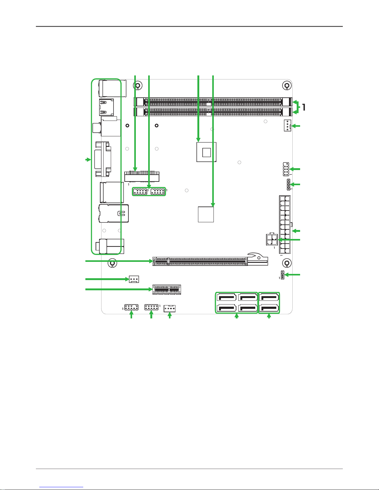
Rear panel
1. PS/2 Keyboard Port
3. HDMI Port (Optional)
5. VGA Port
2. USB Connectors
4. SPDIF Connectors
6. eSATA Port
6
11
5
10
15
234
5
8
7
2
6
Figure 2
6
11
5
10
15
9
8. LAN Connector
Lan Port with LEDs to indicate status.
· Yellow/Light Up/Blink = 10 Mbps/Link/Activity
· Yellow and Green/Light Up/Blink = 100 Mbps/link/Activity
· Yellow and Orange/Light Up/Blink = 1000 Mbps/link/Activity
7. Port 2-Channel 4-Channel 6-Channel
Blue Line-In Rear Speaker Out Rear Speaker Out
Green Line-Out Front Speaker Out Front Speaker Out
Pink Mic In Mic In Center/Subwoofer
9. WiFi antenna connector (Optional)
Refer to the following to install the WiFi antenna modules.
Step 1. Secure the MINI PCIE card into the Mini_PCIEX1 slot with screws.
120
240
121
120
240
121
Mini_PCIEX1
slot
MINI PCIE card
120
240
121
120
240
121
Screws
8
Intel® NM10 series Motherboard
120
240
121
120
240
121
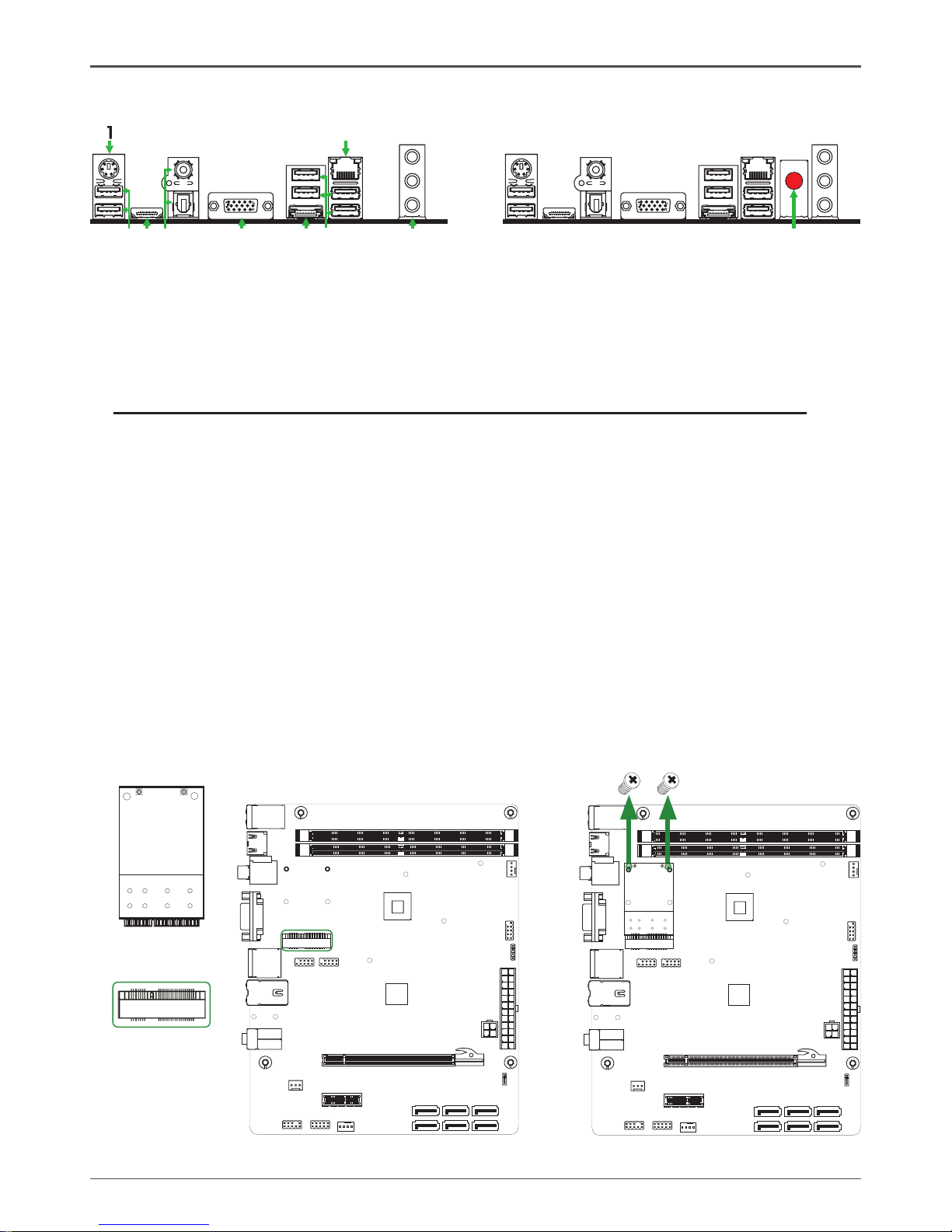
Step 4. Remove the red cap from the WiFi antenna connector.
Install the WiFi antenna to the WiFi antenna connector, and make sure the screw is
rotated in clockwise direction.
Note: 1. Users please note that the appearance of your WiFi antenna modules may
not be exactly the same as those shown in this manual.
2. Users can bend or rotate the WiFi antennas to the best receiving direction
according to the picture below.
Step 2. Secure the bracket to the motherboard with screws according to the picture below.
120
240
121
120
240
121
6
11
5
10
15
Screws
Bracket
Step 3. Connect the WiFi wire to the MINI PCIE card as the following picture shows.
MINI PCIE card
Bracket
WiFi wire
6
11
5
10
15
6
11
5
10
15

9
Hardware Installation
This section will guide you through the installation of the motherboard. The topics covered in this
section are:
q Installing Memory Modules
q Installing the motherboard
q Installing the I/O Shield
q Connecting cables and setting switches
Safety Instructions
To reduce the risk of re, electric shock, and injury, always follow basic safety precautions.
Remember to remove power from your computer by disconnecting the AC main source before
removing or installing any equipment from/to the computer chassis.
Hardware Installation
10
Intel® NM10 series Motherboard
Installing Memory Modules
This motherboard accommodates two memory modules. It can support two 240-pin DDR2
800/667. The total memory capacity is 4 GB. You must install at least one module in any of the
two slots. Refer to the following recommendations to install the memory modules.
q One DIMM: Install it into slot 1 or 2. You can install the DIMM into any slot, however, slot 1
is preferred.
q Two DIMMs: Install them into slot 1 and slot 2
Note that a memory module has a notch, so it can only t in one direction. Refer to the following
procedure to install memory modules into the slots on the motherboard.
1. Unlock a DIMM slot by pressing the module clips outward.
2. Align the memory module to the DIMM slot, and insert the module vertically into the DIMM
slot. The plastic clips at both sides of the DIMM slot automatically lock the DIMM into the
connector.
120
240
121
120
240
121
DDRII-1
DDRII-2

11
Installing the Motherboard
The sequence of installing the motherboard into the chassis depends on the chassis you are
using and if you are replacing an existing motherboard or working with an empty chassis. Deter-
mine if it would be easier to make all the connections prior to this step or to secure the mother-
board and then make all the connections. It is normally easier to secure the motherboard rst.
Use the following procedure to install the I/O shield and secure the motherboard into the chassis.
Note: Be sure that the CPU fan assembly has enough clearance for the chassis covers
to lock into place and for the expansion cards. Also make sure the CPU Fan assem
-bly is aligned with the vents on the covers.
Installing the I/O Shield
The motherboard kit comes with an I/O shield that is used to block radio frequency transmis-
sions, protects internal components from dust and foreign objects, and promotes correct airow
within the chassis.
Before installing the motherboard, install the I/O shield from the inside of the chassis. Press the
I/O shield into place and make sure it ts securely. If the I/O shield does not t into the chassis,
you would need to obtain the proper size from the chassis supplier.
Securing the Motherboard into the Chassis
Most computer chassis have a base with mounting studs or spacers to allow the motherboard
to be secured to the chassis and help to prevent short circuits. If there are studs that do not
align with a mounting hole on the motherboard, it is recommended that you remove that stud
to prevent the possibility of a short circuit. In most cases, it is recommended to secure the
motherboard with spacers.
1. Carefully place the motherboard onto the studs/spacers located inside the chassis.
2. Align the mounting holes with the studs/spacers.
3. Align the connectors to the I/O shield.
4. Ensure that the fan assembly is aligned with the chassis vents according to the fan assembly
instruction.
5. Secure the motherboard with screws.

12
Intel® NM10 series Motherboard
Connecting Cables and Setting Switches
This section takes you through all the connectors and switch settings necessary on the mother-
board. This will include:
q Power Connectors
v 24-pin ATX Power Connector-PW1
v 4-pin ATX_12V Power Connector-PW2
q Internal Headers/Connectors
v SPDIF-Out Header-CN6
v COM Header-COM1
v Front Panel Header-FP1
v USB Headers-FP_U1~FP_U2
v Front Pannel Audio Header-FP_S1
v Speaker Header-SPK1
q Serial-ATA (SATA) Connectors (SATA1~6)
q Fan Connectors
q Expansion Slots
q Jumper Settings
See Figure 1 to locate the connectors and jumpers referenced in the following procedure.
13
Hardware Installation
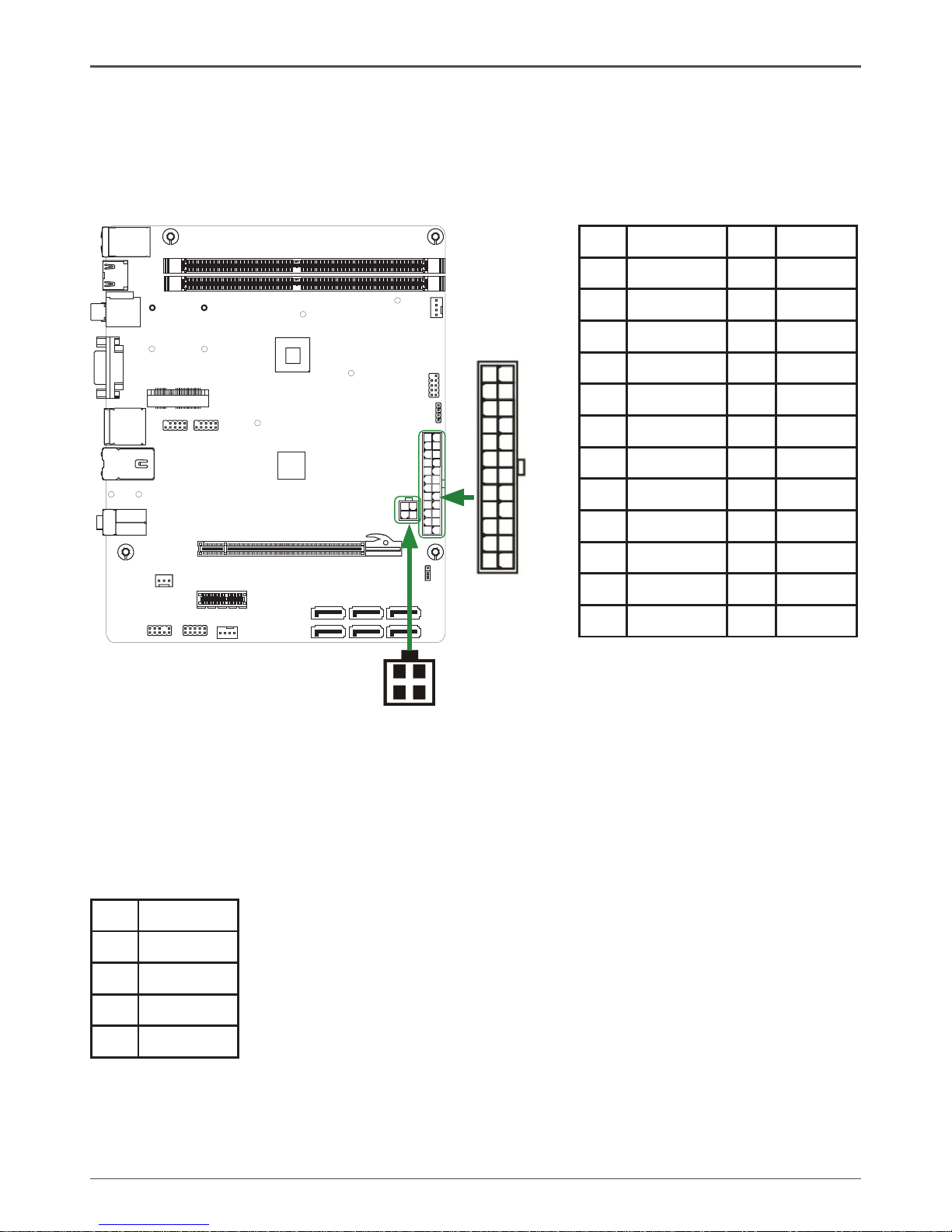
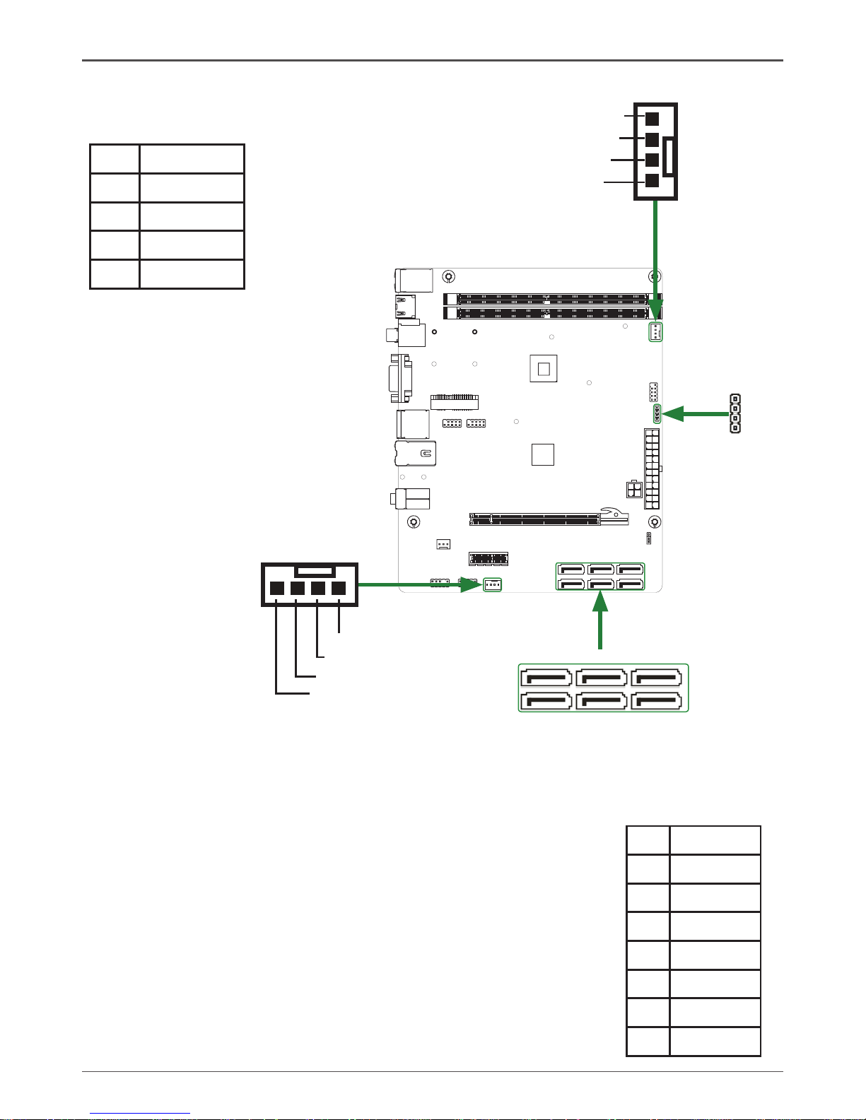
24-pin ATX Power Connector-PW1
PW1 is the main power supply connector. Make sure that the power supply cable and pins are
properly aligned with the connector on the motherboard. Firmly plug the power supply cable into
the connector and make sure it is secure.
4-pin ATX_12V power connector-PW2
PW2, the 4-pin ATX 12V power connection, is used to provide power to the CPU. Align the pins
to the connector and press rmly until seated.
PW2-Pin Denition
Pin Signal
1 GND
2 GND
3 +12V
4 +12V
120
240
121
120
240
121
1
PW2
PW1
PW1-Pin Denition
Pin Signal Pin Signal
1 +3.3V 13 +3.3V
2 +3.3V 14 -12V
3 GND 15 GND
4 +5V 16 PS_ON
5 GND 17 GND
6 +5V 18 GND
7 GND 19 GND
8 PWROK 20 -5V
9 +5V_AUX 21 +5V
10 +12V 22 +5V
11 +12V 23 +5V
12 +3.3V 24 GND
1
12
13
24
14
Intel® NM10 series Motherboard
120
240
121
120
240
121
SPDIF-Out Header-CN6
This header provides a SPDIF (Sony/Philips Digital Interface) output to digital multimedia device
through coaxial connector.
CN6 - Pin Denition
Pin Signal
1 GND
2 SPDIF-out
3 VCC
q PWRLED
Attach the front panel power LED cable to these two pins of the connector. The Power LED
indicates the system’s status.
q PWR SW
Attach the power button cable from the case to these two pins. Pressing the power button
on the front panel turns the system on and off rather than using the power supply button.
q HDD LED
Attach the hard disk drive indicator LED cable to these two pins. The HDD indicator LED
indicates the activity status of the hard disks.
q RST SW
Attach the Reset switch cable from the front panel of the case to these two pins. The system
restarts when the RESET switch is pressed.
Note: Some chassis do not have all four cables. Be sure to match the name on the
connectors to the corresponding pins.
FP1-Pin Denition
Pin Signal Pin Signal
1 HDD_LED+ 2 PW_LED+
3 HDD_LED- 4 PW_LED-
5 GND 6 PWR_SW
7 RESET 8 GND
9 NC 10 KEY
CN6
1
Front panel header-FP1
The front panel header on this motherboard is
one connector used to connect the following
four cables :
FP1
COM1
1
COM1 - Pin Denition
Pin Signal Pin Signal
1 DCD 2 RXD
3 TXD 4 DTR
5 GND 6 DSR
7 RTS 8 CTS
9 RI 10 NC
COM Header-COM1
15
Hardware Installation
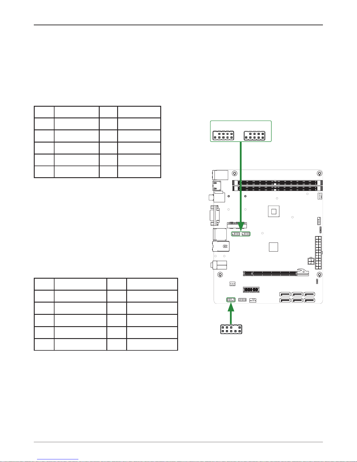
USB Headers-FP_U1~FP_U2
This motherboard contains six USB 2.0 ports that are exposed on the rear panel of the chassis.
The motherboard also contains two 10-pin internal headers onboard.
Note: Secure the bracket to either the front or rear panel of your chassis (not all chassis
are equipped with the front panel option).
120
240
121
120
240
121
Front Panel Audio Header-FP_S1
The audio connector supports HD audio standard and
provides two kinds of audio output choices: the Front
Audio, the Rear Audio. The front Audio supports re-task-
ing function.
Note:
In order to utilize the front audio header, your chassis must have front audio connector.
Also please make sure the pin assignment on the cable is the same as the pin
assignment on the mainboard header. To nd out if the chassis you are buying supports
a front audio connector, please contract your dealer.
FP_S1-Pin Denition
PIN Assignment PIN Assignment
1 MIC2(L) 2 GND
3 MIC(R) 4 -ACZ-DET
5 Front Audio(R) 6 Reserved
7 FAVDIO-JD 8 Key(No pin)
9 Front Audio(L) 10 Reserved
FP_U1~FP_U2-Pin Denition
PIN Assignment PIN Assignment
1 VCC 2 VCC
3 USBP0- 4 USBP1-
5 USBP0+ 6 USBP1+
7 GND 8 GND
9 KEY 10 NC
1
FP_S1
1
FP_U1
1
FP_U2
16
Intel® NM10 series Motherboard
Speaker Header-SPK1
Serial-ATA (SATA) Connectors (SATA1~6)
The Serial ATA connector is used to connect the Serial ATA
device to the motherboard. These connectors support the thin
Serial ATA cables for primary storage devices. The current
Serial ATA interface allows up to 300 MB/s data transfer rate.
There are six serial ATA connectors on the motherboard.
SPK1-Pin Denition
PIN Assignment
1 VCC
2 NC
3 NC
4 SPK-
SATA-Pin Denition
Pin Signal
1 GND
2 TXP
3 TXN
4 GND
5 RXN
6 RXP
7 GND
Fan Connectors
There are two fan connectors on the
motherboard, including system fan
connector-SYS_FAN and CPU fan
connector-CPU_FAN.
SPK1
120
240
121
120
240
121
SATA1
SATA2
1
CPU_FAN
GND
+12V
Sense
Control
SYS_FAN
GND
+12V
Sense
Control
SATA4
SATA5
SATA3
SATA6
Note: The data transmission of SATA3~SATA6 is converted
via onboard SATA multiplier chip (RAID0/1 or RAID0/1/10
for different models).
 Loading...