

Page 1
Page 2

1
Federal Communications Commission (FCC) Statement
This equipment has been tested and found to comply with the limits for a Class B digital device,
pursuant to Part 15 of FCC Rules. These limits are designed to provide reasonable protection
against harmful interference in a residential installation. This equipment generates, uses and
can radiate radio frequency energy and, if not installed and used in accordance with instructions
contained in this manual, may cause harmful interference to radio and television communications.
However, there is no guarantee that interference will not occur in a particular installation.
If this equipment does cause harmful interference to radio or television reception, which can
be determined by turning the equipment off and on, the user is encouraged to try to correct the
interference by one or more of the following measures:
- REORIENT OR RELOCATE THE RECEIVING ANTENNA
- INCREASE THE SEPARATION BETWEEN THE EQUIPMENT AND THE RECEIVER
- CONNECT THE EQUIPMENT INTO AN OUTLET ON A CIRCUIT DIFFERENT FROM
THAT OF THE RECEIVER
- CONSULT THE DEALER OR AN EXPERIENCED AUDIO/TELEVISION TECHNICIAN
NOTE:
Connecting this device to peripheral devices that do not comply with Class B requirements, or
using an unshielded peripheral data cable, could also result in harmful interference to radio or
television reception.
The user is cautioned that any changes or modications not expressly approved by the party
responsible for compliance could void the user’s authority to operate this equipment.
To ensure that the use of this product does not contribute to interference, it is necessary to use
shielded I/O cables.
CE Declaration of conformity
This equipment complies with the requirements relating to electromagnetic compatibility, EN
55022 class A for ITE, the essential protection requirements of Council Directive 89/336/EEC on
the approximation of the laws of the Member States relating to electromagnetic compatibility.
Canadian Department of Communication Statement
This digital apparatus does not exceed the Class B limits for radio noise emissions from
digital apparatus set out in the Radio Interference Regulations of the Canadian Department of
Communications.
This class B digital apparatus complies with Canadian ICES-003.
Electronic Emission Notices
WARNING!
Page 3

2
ZOTAC nForce 790i-Supreme SLI Motherboard
Copyright© 2007 ZOTAC International (MCO) Limited. All Rights Reserved
No part of this manual, including the products and software described in it, may be reproduced,
transmitted, transcribed, stored in a retrieval system, or translated into any language in any form by
any means, without the express written permission of ZOTAC International (MCO) Limited.
Product warranty or service will not be extended if: (1) the product is repaired, modied or altered,
unless such repair, modication or alteration is authorized in writing by ZOTAC International (MCO)
Limited, or (2) the serial number of the product is damaged or missing.
ZOTAC INTERNATIONAL (MCO) LIMITED PROVIDES THIS MANUAL “AS IS” WITHOUT WARRANTY
OF ANY KIND, EITHER EXPRESS OR IMPLIED, INCLUDING BUT NOT LIMITED TO THE IMPLIED
WARRANTIES OR CONDITIONS OF MERCHANTABILITY OR FITNESS FOR A PARTICULAR
PURPOSE. IN NO EVENT SHALL ZOTAC INTERNATIONAL (MCO) LIMITED BE LIABLE FOR ANY
INDIRECT, SPECIAL, INCIDENTAL, OR CONSEQUENTIAL DAMAGES (INCLUDING DAMAGES
FOR LOSS OF PROFITS, LOSS OF BUSINESS, LOSS OF USE OR DATA, INTERRUPTION OF
BUSINESS AND THE LIKE), EVEN IF PC PARTNER HAS BEEN ADVISED OF THE POSSIBILITY OF
SUCH DAMAGES ARISING FROM ANY DEFECT OR ERROR IN THIS MANUAL OR PRODUCT.
SPECIFICATIONS AND INFORMATION CONTAINED IN THIS MANUAL ARE FURNISHED FOR
INFORMATIONAL USE ONLY, AND ARE SUBJECT TO CHANGE AT ANY TIME WITHOUT NOTICE,
AND SHOULD NOT BE CONSTRUCTED AS A COMMITMENT BY ZOTAC INTERNATIONAL
(MCO) LIMITED. ZOTAC INTERNATIONAL (MCO) LIMITED ASSUMES NO RESPONSIBILITY
OR LIABILITY FOR ANY ERRORS OR INACCURACIES THAT MAY APPEAR IN THIS MANUAL,
INCLUDING THE PRODUCTS AND SOFTWARE DESCRIBED IN IT.
Products and corporate names appearing in this manual may or may not be registered trademarks or
copyrights of their respective companies, and are used only for identication or explanation and to the
owner’s benet, without intent to infringe.
NVIDIA is a trademark of NVIDIA Corporation
Windows is a trademark of Microsoft Corp.
Page 4

3
Table of Contents
Before You Begin ---------------------------------------------------------------------------------- 7
Parts NOT in the Kit --------------------------------------------------------------------------- 7
Intentions of the Kit ---------------------------------------------------------------------------- 7
ZOTAC nForce 790i-Supreme SLI Motherboard ---------------------------------------- 8
Motherboard Specications ----------------------------------------------------------------- 8
Unpacking and Parts Descriptions --------------------------------------------------------- 10
Unpacking ---------------------------------------------------------------------------------------- 10
ZOTAC nForce 790i-Supreme SLI Motherboard ---------------------------------------- 11
Hardware Installation ---------------------------------------------------------------------------- 13
Safety Instructions ----------------------------------------------------------------------------- 13
Preparing the Motherboard -------------------------------------------------------------------- 14
Installing the CPU ------------------------------------------------------------------------------ 14
Installing the CPU Fan ------------------------------------------------------------------------ 15
Installing Memory DIMMs -------------------------------------------------------------------- 15
Installing the Motherboard ------------------------------------------------------------------- 16
Installing the I/O Shield ----------------------------------------------------------------------- 16
Securing the Motherboard into the Chassis --------------------------------------------- 16
Connecting Cables and Setting Switches ------------------------------------------------ 17
Power Connections ---------------------------------------------------------------------------- 17
24-pin ATX Power (PWR1) ------------------------------------------------------------------ 18
8-pin ATX 12V Power (PWR2) -------------------------------------------------------------- 19
Connecting IDE Hard Disk Drives --------------------------------------------------------- 19
Connecting Serial ATA Cables -------------------------------------------------------------- 20
Connecting Internal Headers ---------------------------------------------------------------- 21
Front Panel Header ---------------------------------------------------------------------------- 21
IEEE 1394---------------------------------------------------------------------------------------- 22
USB Headers------------------------------------------------------------------------------------ 23
Audio ---------------------------------------------------------------------------------------------- 24
Fan Connections ------------------------------------------------------------------------------- 25
COM1 --------------------------------------------------------------------------------------------- 26
FDD Connector --------------------------------------------------------------------------------- 26
Expansion Slots -------------------------------------------------------------------------------- 27
Table of Contents
Page 5

4
ZOTAC nForce 790i-Supreme SLI Motherboard
PCI Slots ----------------------------------------------------------------------------------------- 27
PCI Express x1 Slot --------------------------------------------------------------------------- 27
PCI Express x16 Slots ------------------------------------------------------------------------ 28
Jumper Settings -------------------------------------------------------------------------------- 28
Clear CMOS Jumper: CLR_CMOS -------------------------------------------------------- 28
Conguring the BIOS ---------------------------------------------------------------------------- 29
Enter BIOS Setup ------------------------------------------------------------------------------ 29
Main Menu ------------------------------------------------------------------------------------------- 30
Standard CMOS Features Menu -------------------------------------------------------------- 32
Date and Time ---------------------------------------------------------------------------------- 33
IDE Channel and SATA Channel ----------------------------------------------------------- 33
Drive A -------------------------------------------------------------------------------------------- 35
Halt On -------------------------------------------------------------------------------------------- 35
Memory ------------------------------------------------------------------------------------------- 36
Advanced BIOS Features ----------------------------------------------------------------------- 37
Removable Device Priority ------------------------------------------------------------------ 38
Hard Disk Boot Priority ----------------------------------------------------------------------- 38
Network Boot Priority -------------------------------------------------------------------------- 38
CPU Internal Cache --------------------------------------------------------------------------- 38
Quick Power On Self Test -------------------------------------------------------------------- 38
First/Second/Third Boot Device ------------------------------------------------------------ 39
Boot Other Device ----------------------------------------------------------------------------- 39
Boot Up NumLock Status -------------------------------------------------------------------- 39
Security Option --------------------------------------------------------------------------------- 39
APIC Mode--------------------------------------------------------------------------------------- 39
MPS Version Control For OS --------------------------------------------------------------- 40
Full Screen LOGO Show --------------------------------------------------------------------- 40
Advanced Chipset Features ------------------------------------------------------------------- 41
System Clocks ---------------------------------------------------------------------------------- 42
Frequency Settings ---------------------------------------------------------------------------- 43
HT Multiplier ------------------------------------------------------------------------------------- 43
Spread Spectrum ------------------------------------------------------------------------------ 44
FSB & Memory Cong ------------------------------------------------------------------------ 45
Page 6

5
CPU Conguration ----------------------------------------------------------------------------- 49
System Voltages ------------------------------------------------------------------------------- 51
NVMEM Memory Test ------------------------------------------------------------------------- 53
Load Timing/Voltage Set --------------------------------------------------------------------- 53
Save Timing/Voltage Set --------------------------------------------------------------------- 53
System BIOS Cacheable --------------------------------------------------------------------- 53
HPET Function ---------------------------------------------------------------------------------- 53
NVIDIA GPU Ex -------------------------------------------------------------------------------- 53
Integrated Peripherals Menu ------------------------------------------------------------------ 54
IDE Function Setup ---------------------------------------------------------------------------- 55
RAID Cong ------------------------------------------------------------------------------------- 56
USB Cong -------------------------------------------------------------------------------------- 56
MAC Cong -------------------------------------------------------------------------------------- 57
IEEE1394 controller --------------------------------------------------------------------------- 57
HD Audio ----------------------------------------------------------------------------------------- 57
IDE HDD Block Mode ------------------------------------------------------------------------- 57
Onboard FDC Controller --------------------------------------------------------------------- 57
Onboard Serial Port 1 ------------------------------------------------------------------------- 57
Power Management Setup Menu ------------------------------------------------------------ 58
ACPI Function----------------------------------------------------------------------------------- 58
ACPI Suspend Type --------------------------------------------------------------------------- 58
Soft-Off by PBNT ------------------------------------------------------------------------------- 58
WOL(PME#) From Soft-Off ------------------------------------------------------------------ 58
Power On by Alarm ---------------------------------------------------------------------------- 59
POWER ON Function ------------------------------------------------------------------------- 59
PnP/PCI Conguration Menu ------------------------------------------------------------------ 60
Init Display First--------------------------------------------------------------------------------- 60
Reset Conguration Data -------------------------------------------------------------------- 60
Resources Controlled By --------------------------------------------------------------------- 61
IRQ Resources --------------------------------------------------------------------------------- 61
PCI/VGA Palette Snoop ---------------------------------------------------------------------- 61
Maximum Payload Size ---------------------------------------------------------------------- 61
Table of Contents
Page 7

6
ZOTAC nForce 790i-Supreme SLI Motherboard
Pc Health Status ----------------------------------------------------------------------------------- 62
Dynamic Fan Control -------------------------------------------------------------------------- 63
Installing Drivers and Software -------------------------------------------------------------- 64
Drivers Installation ----------------------------------------------------------------------------- 64
Using the NVIDIA Software -------------------------------------------------------------------- 65
NVIDIA Performance Group of NVIDIA Control Panel -------------------------------- 65
Device Settings ------------------------------------------------------------------------------------ 66
Current Hardware Settings ------------------------------------------------------------------ 66
Motherboard ------------------------------------------------------------------------------------- 67
Memory ------------------------------------------------------------------------------------------- 69
GPU ----------------------------------------------------------------------------------------------- 72
Dynamic BIOS Access ------------------------------------------------------------------------ 73
View System Information --------------------------------------------------------------------- 74
Prole Policies ---------------------------------------------------------------------------------- 75
Manage Your System BIOS ----------------------------------------------------------------- 76
NVIDIA System Monitor ------------------------------------------------------------------------- 77
Appendix A. Conguring an SLI Conguration ----------------------------------------- 81
SLI Connector ----------------------------------------------------------------------------------- 81
ForceWare Driver ------------------------------------------------------------------------------ 82
Enabling 3-Way SLI --------------------------------------------------------------------------- 83
Verifying 3-way SLI is Active ---------------------------------------------------------------- 85
Appendix B. POST Codes for Tritium Platform ----------------------------------------- 86
Award POST Codes --------------------------------------------------------------------------- 86
NVMM POST Codes -------------------------------------------------------------------------- 93
Page 8

7
Before You Begin…
Parts NOT in the Kit
This kit contains all the hardware necessary to install and connect your new ZOTAC®
nForce® 790i-Supreme SLI motherboard. However, it does not contain the following
items that must be purchased separately to make the motherboard functional.
q Intel microprocessor:
Intel Core 2 Extreme, Intel Core 2 Quad, Intel Core 2 Duo Pentium EE, Pentium D
q Cooling fan for the microprocessor
q System memory support:
Supports dual channel DDR3 800/1066/1333, and up to 2000 MHz SLI-Ready
Memory. Supports up to 8 GBs DDR3 memory.
q Graphics Card
This motherboard supports 3-way SLI with three x16 PCI Express slots.
q Power Supply
The power supply requirement is dependent upon the power and the number of
the GPUs you install. If you are going to SLI two graphics cards, you are going
to require more power. As a rule, for one GPU you need a minimum of a 300 W
power supply. If you have two GPUs in an SLI conguration, you will need a
minimum of a 500 W power supply. If you have three GPUs in an SLI
conguration, you will need a minimum of a 1000 W power supply. To calculate
the power you are going to require for your specic conguration, go to
www.slizone.com.
These instructions tell you how to install each of the parts listed so you can have
a functioning motherboard. As you go through the installation instructions, we are
assuming you have purchased the necessary parts.
Intentions of the Kit
This kit provides you with the motherboard and all connecting cables necessary to
install the motherboard into a PC cabinet. If you are building a PC, you will use most
of the cables provided in the kit. If however, you are replacing a motherboard, you will
not need many of the cables.
When replacing a motherboard in a PC cabinet, you will need to reinstall an operating
system even though the current drives have an operating system.
Before You Begin
Page 9

8
ZOTAC nForce 790i-Supreme SLI Motherboard
ZOTAC nForce 790i-Supreme Motherboard
Thank you for buying the ZOTAC nForce 790i-Supreme SLI motherboard. This
motherboard offers the tools and performance PC users’ demand. When combined
with two or three SLI-Ready NVIDIA GeForce graphics cards, you get innovative
NVIDIA SLI Technology for enhanced system performance.
Motherboard Specications
q Size
ATX form factor of 12 inch x 9.6 inch
q Microprocessor support
Intel Core 2 Extreme, Intel Core 2 Quad, Intel Core 2 Duo, Pentium EE, Pentium D
q Operating systems:
Supports Windows XP 32bit/64bit and Windows Vista 32bit/64bit
q Contains NVIDIA nForce 790i SLI MCP and SPP
q System Memory support
Supports dual channel DDR3 800/1066/1333 and SLI-Ready memory up to
2000 MHz. Supports up to 8 GBs DDR3 memories.
q Ten USB 2.0 Ports
v Supports hot plug
v Ten USB 2.0 ports (six rear panel ports, four onboard USB headers)
v Supports wake-up from S1 and S3 mode
v Supports USB 2.0 protocol up to 480 Mbps transmission rate
q Onboard Serial ATA II
v 300MBps data transfer rate
v Six Serial ATA II connectors
v NVIDIA MediaShield RAID with support for RAID 0, RAID 1, RAID 0+1,
RAID 5, and JBOD
v Supports hot plug and NCQ (Native Command Queuing )
q Onboard LAN
v Dual LAN interface built-in onboard
v Supports 10/100/1000 Mbit/sec Ethernet
Page 10

9
q Onboard 1394
v Support hot plug
v Two 1394 ports (one rear panel port, one onboard header) with rate of
transmission at 400 Mbps
q Onboard Audio
v Azalia High-Denition audio
v Supports 8-channel audio
v Supports S/PDIF output
v Supports Jack-Sensing function
q Triple PCI Express x16 Support
v 2 x16 PCI Express 2.0
v 1 x16 PCI Express 1.0
v Supports 4 GB/sec (8 GB/sec concurrent) bandwidth
v Low power consumption and power management features
q Green Function
v Supports ACPI (Advanced Conguration and Power Interface)
v Supports S0 (normal), S1 (power on suspend), S3 (suspend to RAM),
S4 (Suspend to disk - depends on OS), and S5 (soft - off)
q Expansion Slots
v Two PCI slots
v Two PCI Express x1 slots
v Three PCI Express x16 Graphics slots
Specications
Page 11

10
ZOTAC nForce 790i-Supreme SLI Motherboard
Unpacking and Parts Descriptions
Unpacking
The ZOTAC nForce 790i-Supreme SLI motherboard comes with all the necessary
cables for adding a motherboard to a new chassis. If you are replacing a motherboard,
you may not need many of these cables.
Be sure to inspect each piece of equipment shipped in the packing box. If anything is
missing or damaged, contact your reseller.
All parts shipped in this kit are RoHS-compliant (lead-free) parts.
Page 12

11
ZOTAC nForce 790i-Supreme Motherboard
The ZOTAC nForce 790i-Supreme SLI motherboard with the NVIDIA nForce 790i SLI
SPP and MCP processors is a PCI Express, SLI-ready motherboard. Figure 1 shows
the motherboard and Figures 2 shows the back panel connectors.
1. CPU Socket 11. Fan connectors 21. PCI slots
2. NVIDIA 790i Ultra SLI heatpipe 12. Serial-ATA (SATA) connectors 22. PCI Express x16 slots (SLI)
3. CPU fan connector 13. Front panel connector 23. PCI Express x1 slots
4. DDR3 DIMM Slots 0 - 3 14. Serial connector 24. SATA connectors
5. 24-pin ATX Power Connector 15. Jumper 25. Backpanel connectors(Figure 2)
6. IDE Connector 16. USB headers 26. Heat dissipater
7. Serial-ATA (SATA) connectors 17. 1394a connector 27. 8-pin ATX_12V power connector
8. FDD connector 18. Power button 28. MCP/SPP fan connector
9. NVIDIA MCP (passive heat sink) 19. Reset Button 29. Motherboard battery
10. Diagnostic code display 20. FP Audio connector
Motherboard Layout
Figure 1. Board Layout
Page 13
12
ZOTAC nForce 790i-Supreme SLI Motherboard
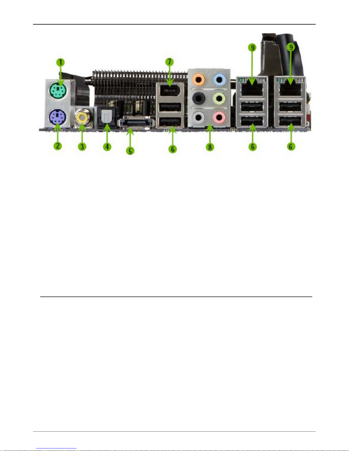
1. PS/2 Mouse Port
2. PS/2 Keyboard Port
3. Coaxial SPDIF
4. SPDIF output
5. eSATA
6. USB 2.0 ports (SIX)
7. 1394 (Firewire) Port
8. Port 2-Channel 4-Channel 6-Channel/8-Channel
Blue Line-In Line-In Line-In
Green Line-Out Front Speaker Out Front Speaker Out
Pink Mic In Mic In Mic In
Orange -- -- Center/Subwoofer
Black -- Rear Speaker Out Rear Speaker Out
Grey -- -- Side Speaker Out
9. Lan Port with LEDs to indicate status.
· Yellow/Light Up/Blink = 10 Mbps/Link/Activity
· Yellow and Green/Light Up/Blink = 100 Mbps/link/Activity
· Green/Light Up/Blink = 1000 Mbps/Link/Activity
Figure 2. Backpanel
Page 14

13
Hardware Installation
This section will guide you through the installation of the motherboard. The topics
covered in this section are:
q Preparing the motherboard
v Installing the CPU
v Installing the CPU fan
v Installing the memory
q Installing the motherboard
q Connecting cables and setting switches
Safety Instructions
To reduce the risk of re, electric shock, and injury, always follow basic safety precations.
Remember to remove power from your computer by disconnecting the AC main source
before removing or installing any equipment from/to the computer chassis.
Hardware Installation
Page 15
14
ZOTAC nForce 790i-Supreme SLI Motherboard
Preparing the Motherboard
The motherboard shipped in the box does not contain a CPU or memory. You need to
purchase these to complete this installation.
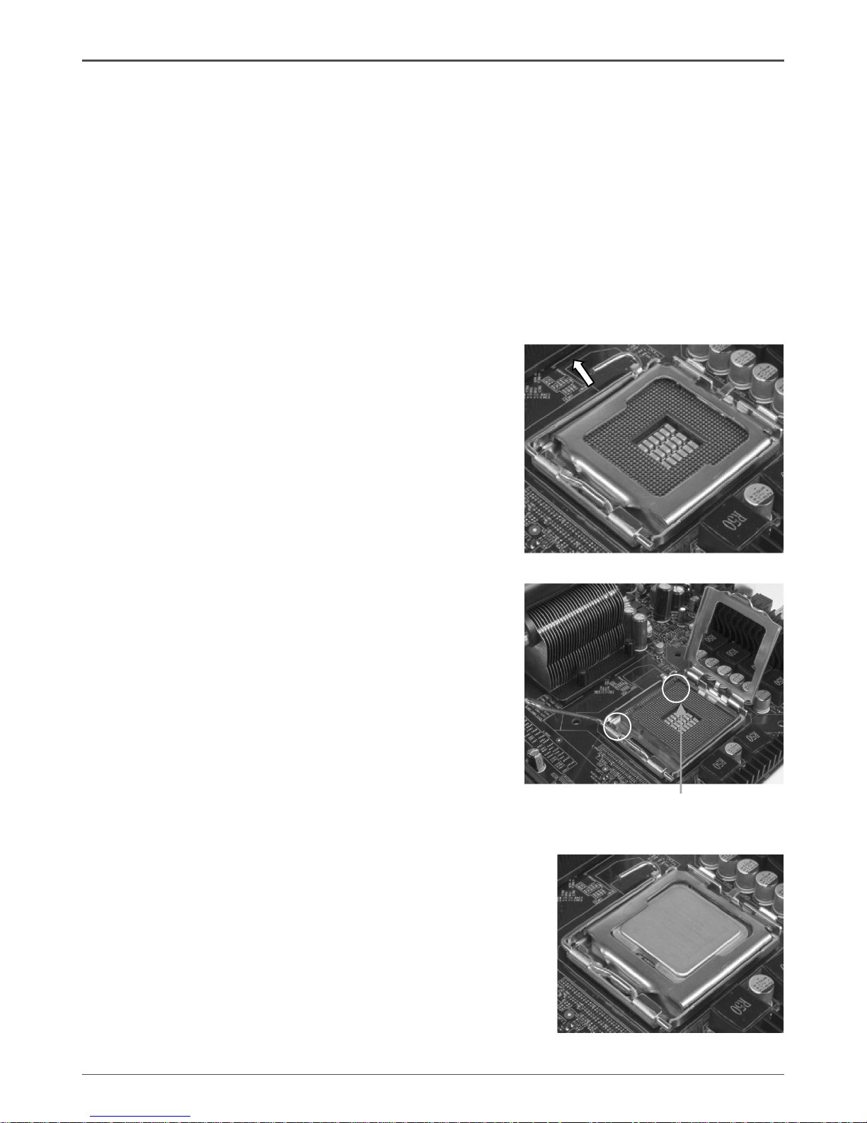
Installing the CPU
Be very careful when handling the CPU. Make sure not to bend or break any pins on
the back. Hold the processor only by the edges and do not touch the bottom of the
processor.
Use the following procedure to install the CPU onto the motherboard.
1. Unhook the socket lever by pushing down and
away from the socket.
2. Lift the load plate. There is a protective socket
cover on the load plate to protect the socket
when there is no CPU installed.
3. Remove the protective socket cover from the
load plate.
4. Remove the processor from its protective cover,
making sure you hold it only by the edges.
It is a good idea to save the cover so that
whenever you remove the CPU, you have a
safe place to store it.
5. Align the notches in the processor with the
notches on the socket.
6. Lower the processor straight down into the
socket with out tilting or sliding it into the socket.
Note: Make sure the CPU is fully seated and
level in the socket.
7. Close the load plate over the CPU and press
down while you close and engage the socket
lever.
Align notches with notches
on the CPU
Page 16
15
Installing the CPU Fan
There are many different fan types that can be used with this motherboard. Follow the
instruction that came with you fan assembly. Be sure that the fan orientation is correct
for your chassis type and your fan assembly.
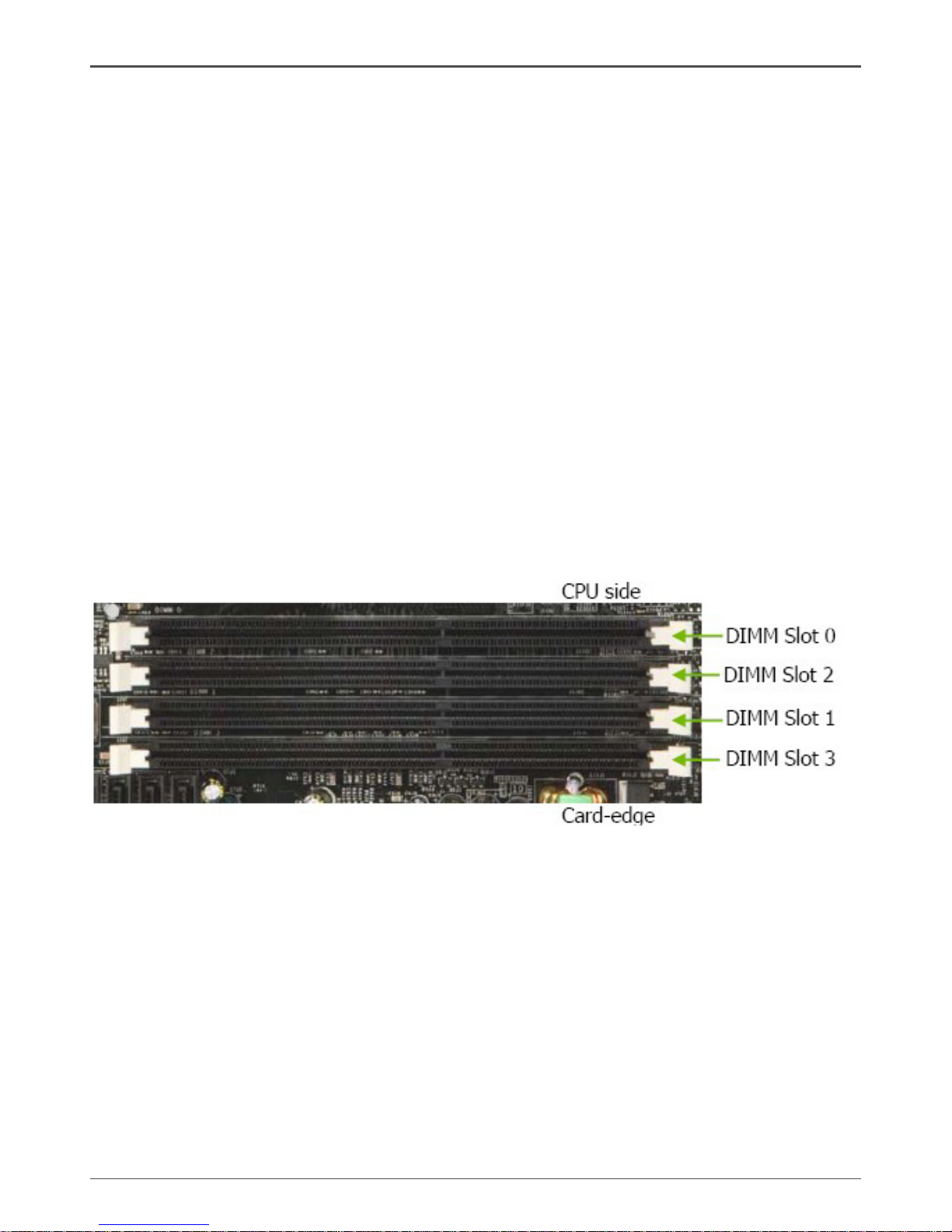
Installing Memory DIMMs
Your new motherboard has four 240-pin slots for DDR3 memory. These slots support
256 Mb, 512 Mb and 1 Gb DDR3 technologies for x8 and x16 devices. There must be
at least one memory bank populated to ensure normal operation. Use the following
the recommendations for installing memory.
q One DIMM: Install into slot 0. You can install the DIMM into any slot, however,
slot 0 is preferred.
q Two DIMMs: Install into either slots 0 and 1 or 2 and 3. The idea is to not have
the DIMMs in adjacent slots.
q Four DIMMS: Install into slots 0, 1, 2, and 3.
Use the following procedure to install memory DIMMs into the slots on the
motherboard. Note that there is only one gap near the center of the DIMM slot. This
slot matches the slot on the memory DIMM to ensure the component is installed
properly.
1. Unlock a DIMM slot by pressing the module clips outward.
2. Align the memory module to the DIMM slot, and insert the module vertically into
the DIMM slot. The plastic clips at both sides of the DIMM slot automatically lock
the DIMM into the connector.
Hardware Installation
Page 17

16
ZOTAC nForce 790i-Supreme SLI Motherboard
Installing the Motherboard
The sequence of installing the motherboard into the chassis depends on the chassis
you are using and if you are replacing an existing motherboard or working with an
empty chassis. Determine if it would be easier to make all the connections prior to this
step or to secure the motherboard and then make all the connections. It is normally
easier to secure the motherboard rst.
Use the following procedure to install the I/O shield and secure the motherboard into
the chassis.
Note: Be sure that the CPU fan assembly has enough clearance for the
chassis covers to lock into place and for the expansion cards. Also
make sure the CPU Fan assembly is aligned with the vents on the
covers.
Installing the I/O Shield
The motherboard kit comes with an I/O shield that is used to block radio frequency
transmissions, protects internal components from dust and foreign objects, and
promotes correct airow within the chassis.
Before installing the motherboard, install the I/O shield from the inside of the chassis.
Press the I/O shield into place and make sure it ts securely. If the I/O shield does
not t into the chassis, you would need to obtain the proper size from the chassis
supplier.
Securing the Motherboard into the Chassis
Most computer chassis have a base with mounting studs or spacers to allow the
mother board to be secured to the chassis and help to prevent short circuits.
If there are studs that do not align with a mounting hole on the motherboard, it is
recommended that you remove that stud to prevent the possibility of a short circuit. In
most cases, it is recommended to secure the motherboard using a minimum of nine
(9) spacers.
1. Carefully place the motherboard onto the studs/spacers located inside the
chassis.
2. Align the mounting holes with the studs/spacers.
3. Align the connectors to the I/O shield.
4. Ensure that the fan assembly is aligned with the chassis vents according to the
fan assembly instruction.
5. Secure the motherboard with a minimum of eight-to-ten screws.
Page 18

17
Connecting Cables and Setting Switches
This section takes you through all the connections and switch settings necessary on
the motherboard. This will include:
q Power Connections
v 24-pin ATX power (PWR1)
v 8-pin ATX 12V power (PWR2)
q Internal Headers
v Front panel
v IEEE 1394
v USB Headers
v Audio
v Speaker
v COM
q FDD
q IDE
q Serial ATA II
q Chassis Fans
q Rear panel USB 2.0 Adapter
q Expansion slots
q CMOS jumper settings
Power Connections
To support 3-way SLI, this motherboard has the following specic power supply
requirements:
q Minimum 1000 W peak power
q Six PCI-E power connectors congured in either of the following congurations
(see Figure 3):
Six 6-pin (3x2) PCI-E power connectors
Figure 3. Power Supply Connectors
Hardware Installation
Page 19

18
ZOTAC nForce 790i-Supreme SLI Motherboard
Make sure you have enough power to cover all the expansion cards you will
be installing. To determine what you power requirements are for your specic
conguration or a certied power supply vendor, refer to www.slizone.com.
24-pin ATX Power (PWR1)
PWR1 is the main power supply connector located along the edge of the board next to
the DIMM slots. Make sure that the power supply cable and pins are properly aligned
with the connector on the motherboard. Firmly plug the power supply cable into the
connector and make sure it is secure.
Figure 4. PWR1 Motherboard Connector
Table 1. PWR1 Pin Assignments
Connector Pin Signal Pin Signal
1 +3.3V 13 +3.3V
2 +3.3V 14 -12V
3 GND 15 GND
4 +5V 16 PS_ON
5 GND 17 GND
6 +5V 18 GND
7 GND 19 GND
8 PWROK 20 RSVD
9 +5V_AUX 21 +5V
10 +12V 22 +5V
11 +12V 23 +5V
12 +3.3V 24 GND
Page 20

19
8-pin ATX 12V Power (PWR2)
PWR2, the 8-pin ATX 12V power connection, is used to provide power to the CPU.
Align the pins to the connector and press rmly until seated.
Connecting IDE Hard Disk Drives
The IDE connector supports Ultra ATA 133/100/66 IDE hard disk drives.
1. Connect the blue connector (the cable end with a single connector) to the
motherboard.
2. Connect the black connector (the cable with the two closely spaced black and
gray connectors) to the Ultra ATA master device.
3. Connect the gray connector to a slave device.
If you install two hard disk drives, you must congure the second drive as a slave
device by setting its jumper accordingly. Refer to the hard disk documentation for the
jumper settings.
Note: If an ATA-66/100/133 disk drive and a disk drive using any other IDE
transfer protocol are attached to the same cable, the maximum transfer
rate between the drives may be reduced to that of the slowest drive.
Hardware Installation
Page 21
20
ZOTAC nForce 790i-Supreme SLI Motherboard
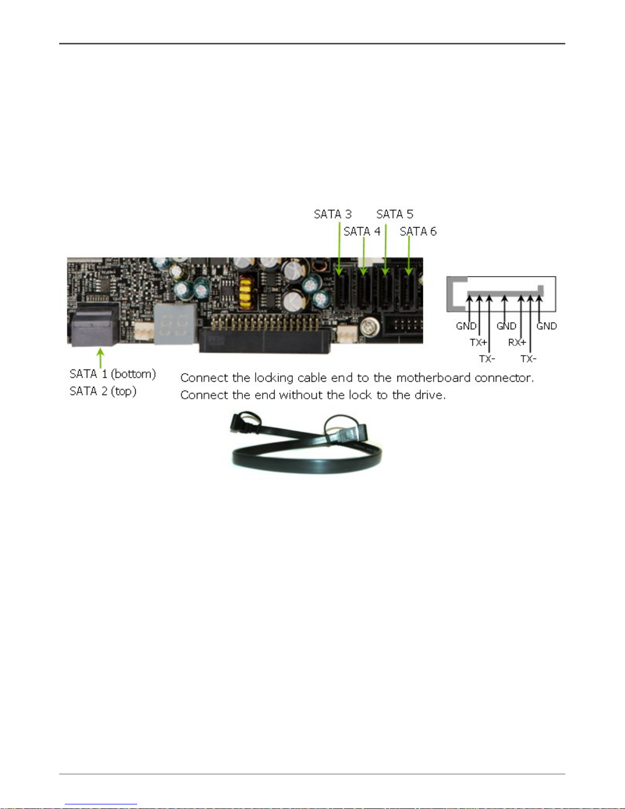
Connecting Serial ATA Cables
The Serial ATA II connector is used to connect the Serial ATA II device to the
motherboard. These connectors support the thin Serial ATA II cables for primary
storage devices. The current Serial ATA II interface allows up to 300MB/s data transfer
rate.
There are six serial ATA connectors on the motherboard that support RAID 0, RAID 1,
RAID 5, RAID 0+1 and JBOD congurations.
Page 22

21
Connecting Internal Headers
Front Panel Header
The front panel header on this motherboard is one connector used
to connect the following four cables (see Table 2 for pin denitions):
q PWRLED
Attach the front panel power LED
cable to these two pins of the
connector. The Power LED indicates
the system’s status. When the
system is in S0 status, the LED is on.
When the system is in S1, S3, S4, S5
status, the LED is off.
Note: Some chassis do not have all four cables. Be sure to match the name on
the connectors to the corresponding pins.
q PWRSW
Attach the power button cable from the case to these two pins. Pressing the
power button on the front panel turns the system on and off rather than using the
power supply button.
q HD_LED
Attach the hard disk drive indicator LED cable to these two pins. The HDD
indicator LED indicates the activity status of the hard disks.
q RESET
Attach the Reset switch cable from the front panel of the case to these two pins.
The system restarts when the RESET switch is pressed.
Table 2. Front Panel Header Pins
Hardware Installation
Page 23
22
ZOTAC nForce 790i-Supreme SLI Motherboard
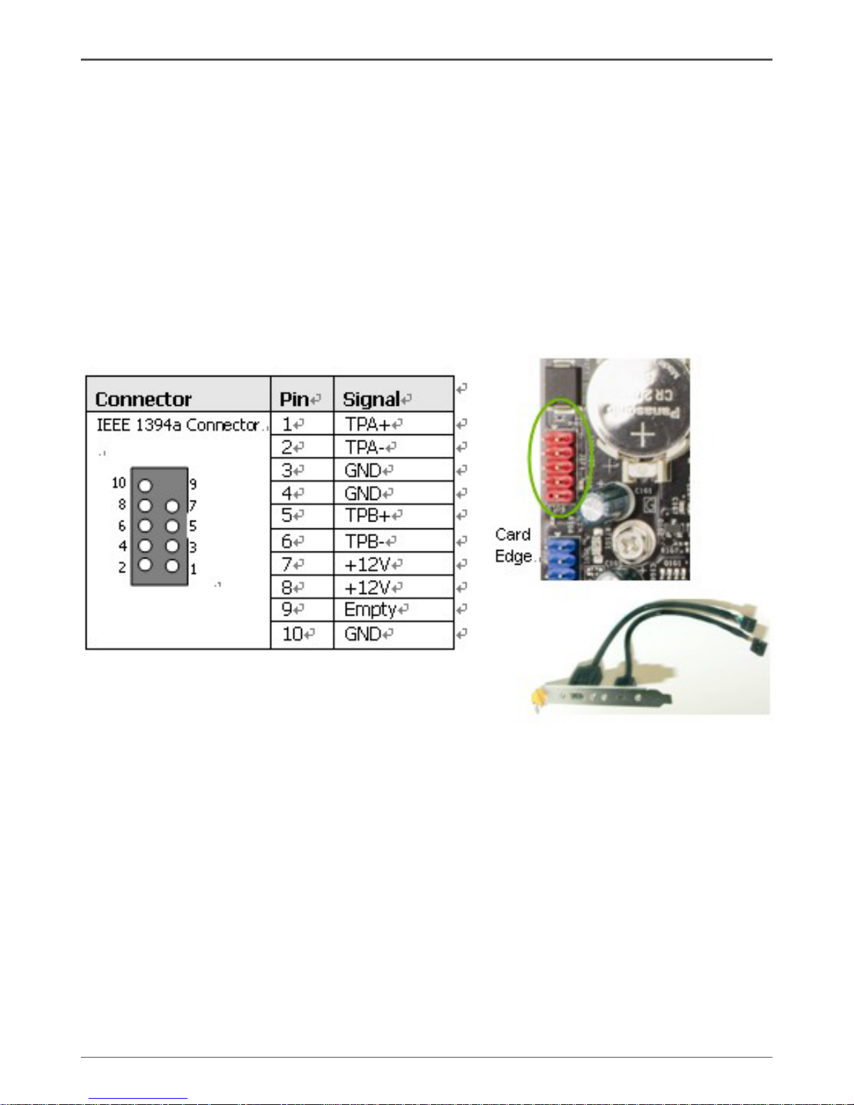
IEEE 1394
The IEEE 1394 expansion cable bracket is provided in the box but if you do not require
the additional external connections, you do not need to install it.
1. Secure the bracket to either the front or rear panel of your chassis (not all
chassis are equipped with the front panel option).
2. Connect the two ends of the cables to the IEEE 1394 connectors on the
motherboard.
Table 3. IEEE 1394 Connector Pins
Page 24
23
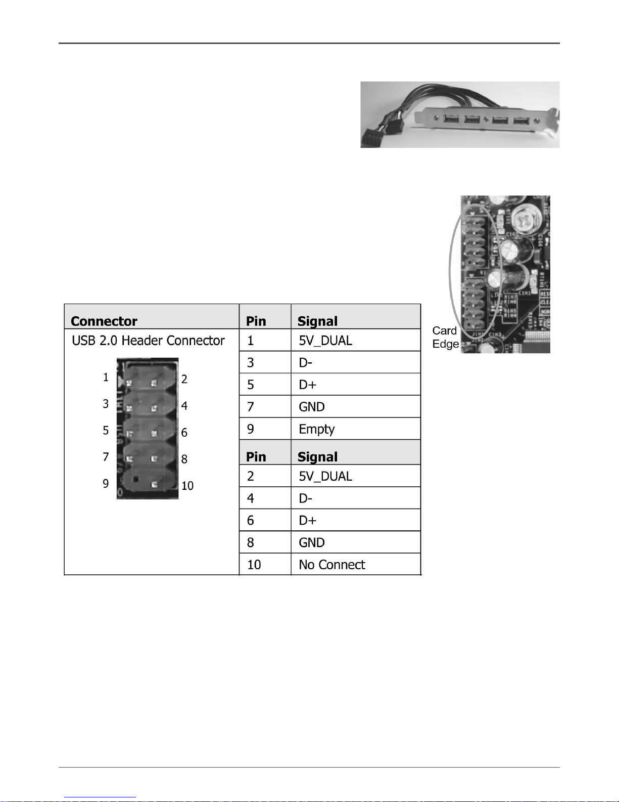
USB Headers
This motherboard contains six (4) USB 2.0 ports
that are exposed on the rear panel of the chassis
(Figure 2). The motherboard also contains two
10-pin internal header connectors onboard.
1. Secure the bracket to either the front or rear panel of your chassis (not all
chassis are equipped with the front panel option).
2. Connect the two ends of the cables to the USB
2.0 headers on the motherboard.
Table 4. USB 2.0 Header Pins
Hardware Installation
Page 25
24
ZOTAC nForce 790i-Supreme SLI Motherboard
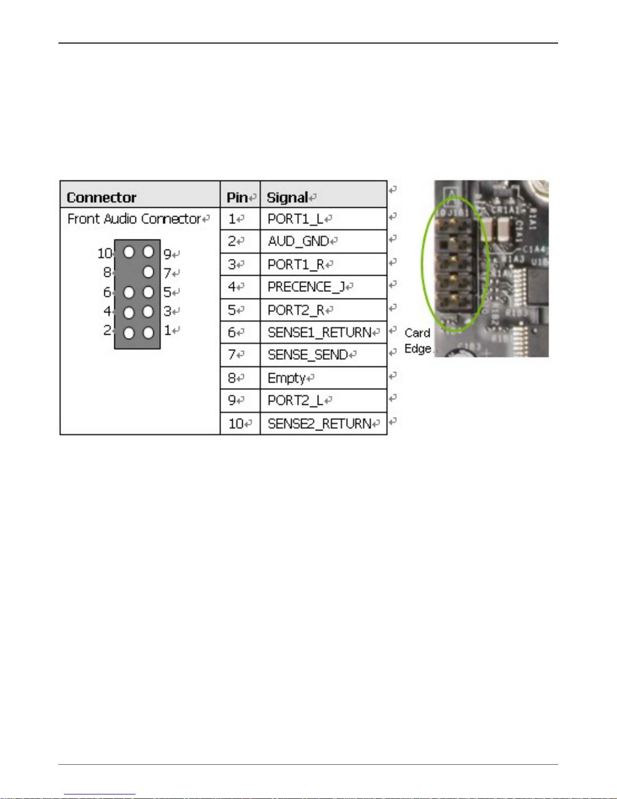
Audio
The audio connector supports HD audio standard and provides two kinds of audio
output choices: the Front Audio, the Rear Audio. The front Audio supports re-tasking
function.
Table 5. Front Audio Connector
Page 26
25
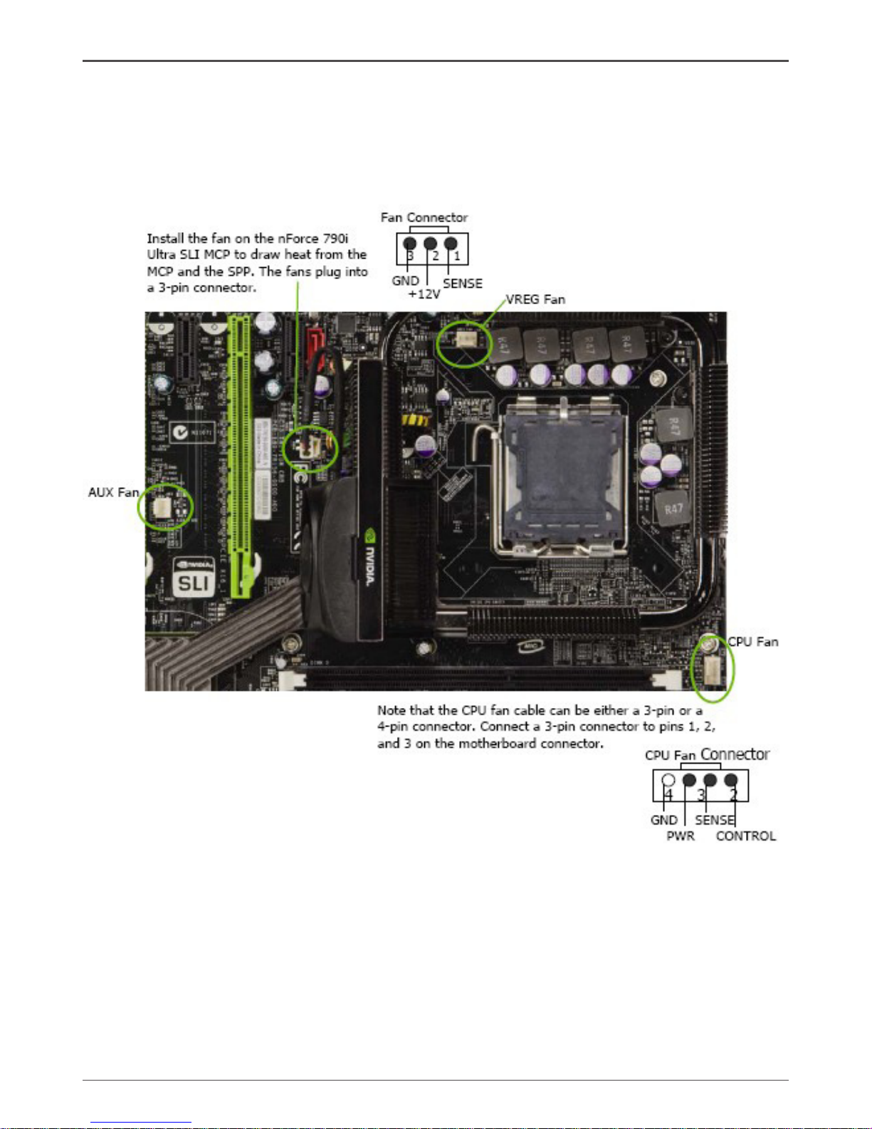
Fan Connections
There are ve fan connections on the motherboard. The fan speed can be detected
and viewed in the PC Health Status section of the CMOS Setup. The fans are
automatically turned off after the system enters S3, S4 and S5 mode.
Hardware Installation
Page 27
26
ZOTAC nForce 790i-Supreme SLI Motherboard
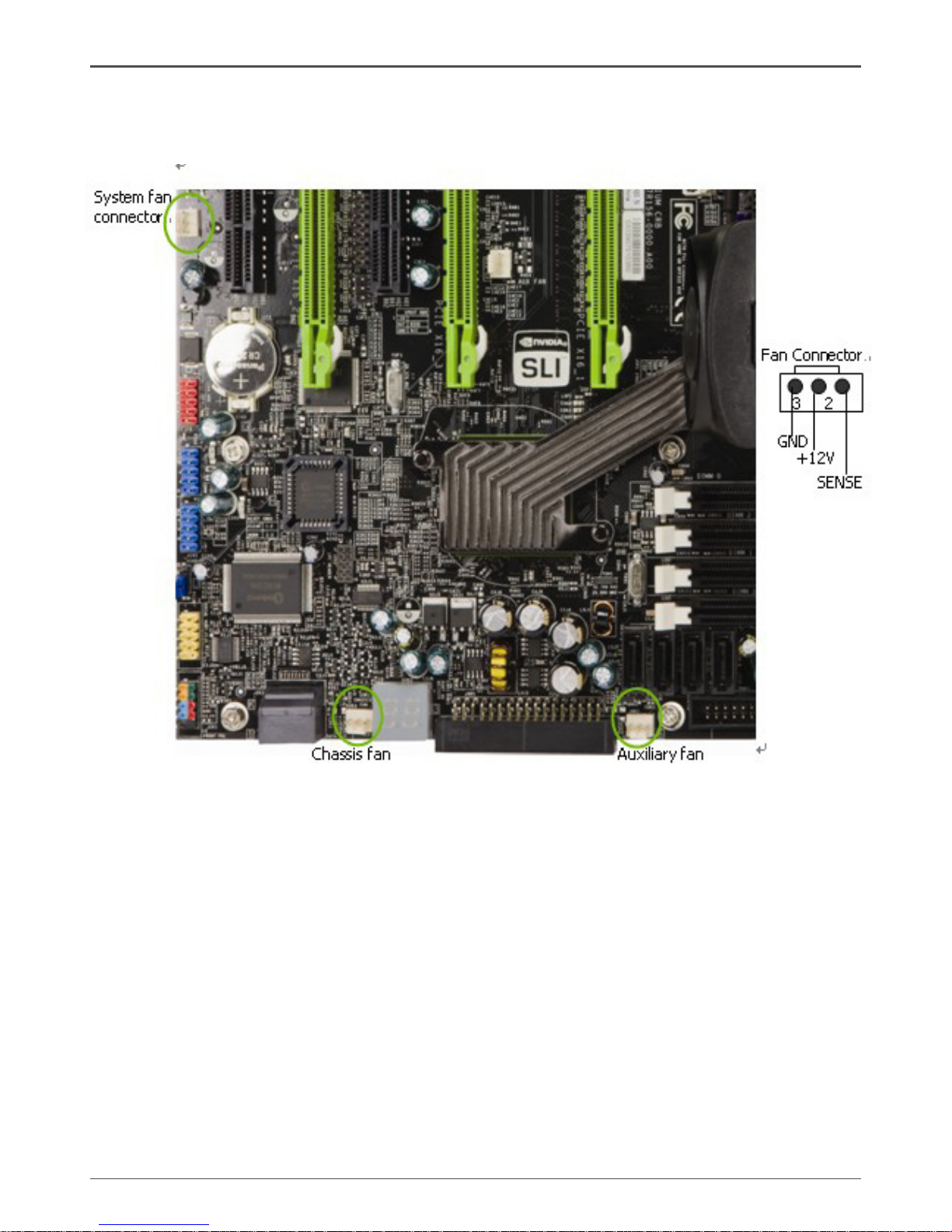
There are ve more fan connectors on the motherboard. For this installation, these
will not be used.
COM1
The motherboard kit provides an additional serial COM header for your machine.
Connect one side of a switching cable to the header and then attach the serial COM
device to the other side of the cable.
FDD Connector
The motherboard supports a standard 360K, 720K, 1.2M, 1.44m, and a 2.88M oppy
disk drive (FDD).
Page 28
27
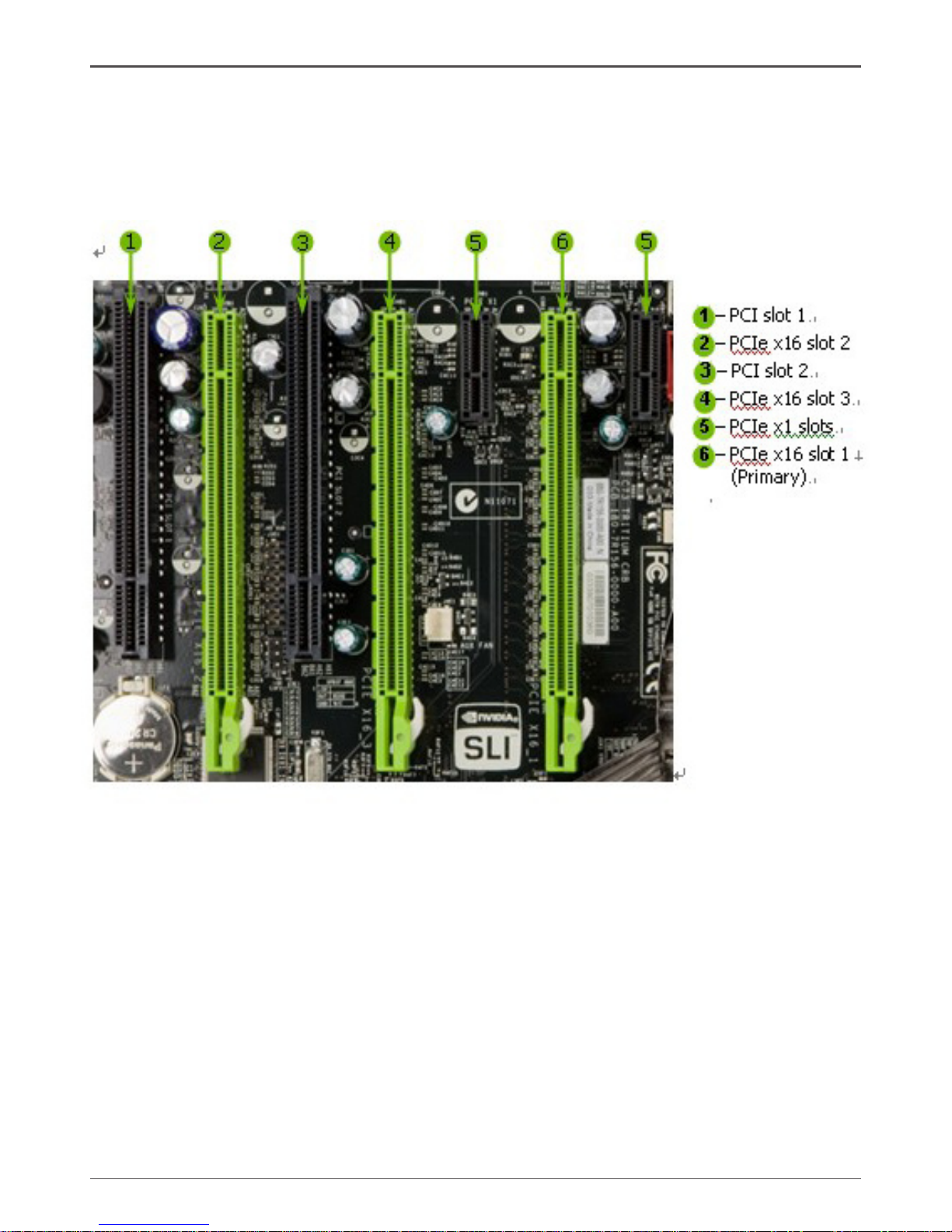
Expansion Slots
The NVIDIA nForce 790i SLI motherboard contains seven expansion slots, ve PCI
Express slots and two PCI slots. For a full list of PCI Express x16 graphics card
supported by this motherboard, go to www.nvidia.com/estore.
PCI Slots
The two PCI slots support many expansion cards such as a LAN card, USB card,
SCSI card and other cards that comply with PCI specications. When installing a card
into the PCI slot, be sure that it is fully seated. Secure the card’s metal bracket to the
chassis back panel with the screw used to hold the blank cover.
PCI Express x1 Slot
There is two PCI Express x1 slot that is designed to accommodate less bandwidthintensive cards, such as a modem or LAN card. The x1 slot provides 250 MB/sec
bandwidth.
Hardware Installation
Page 29
28
ZOTAC nForce 790i-Supreme SLI Motherboard
PCI Express x16 Slots
These three PCI Express x16 slots are reserved for graphics or video cards. The
bandwidth of the x16 slot is up to 4GB/sec (8GB/sec concurrent). The design of
this motherboard supports three PCI-Express graphics cards using NVIDIA’s SLI
technology with multiple displays.
When installing a PCI Express x16 card, be sure the retention clip snaps and locks
the card into place. If the card is not seated properly, it could cause a short across the
pins. Secure the card’s metal bracket to the chassis back panel with the screw used
to hold the blank cover.
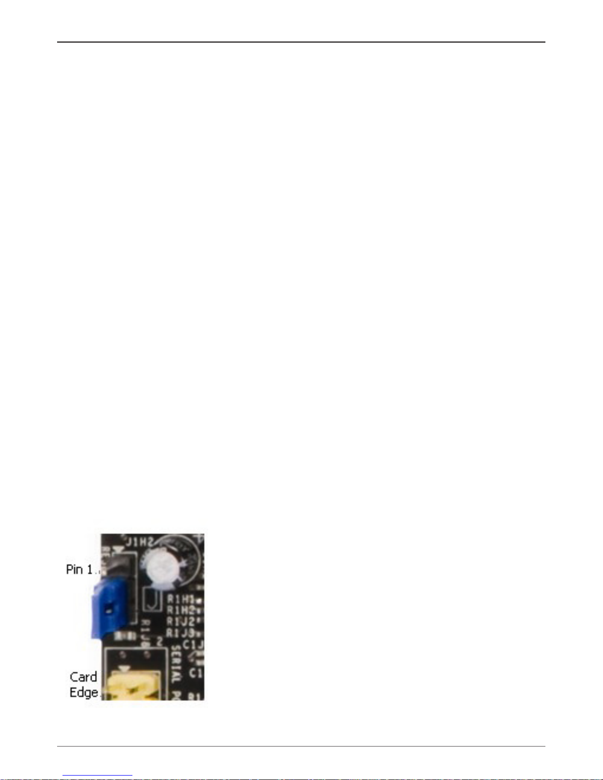
Jumper Settings
The motherboard contains a 3-pin BIOS conguration jumper that enables all board
congurations to be done in the BIOS Setup program.
The silk screen on the motherboard shows a ∆ next to pin 1.
Clear CMOS Jumper: CLR_CMOS
The motherboard uses the CMOS RAM to store all the set parameters. The CMOS
can be cleared by removing the CMOS jumper.
Use the following procedure to clear CMOS:
1. Turn off the AC power supply and connect pins 1 and 2 together using the jumper
cap.
2. Return the jumper setting to normal (pins 2 and 3 together with the jumper cap).
3. Turn the AC power supply back on.
Page 30

29
Conguring the BIOS
This section discusses how to change the system settings through the BIOS Setup
menus. Detailed descriptions of the BIOS parameters are also provided.
This section includes the following information:
q Enter BIOS Setup
q Main Menu
q Standard CMOS Features
q Advanced BIOS Features
q Advanced Chipset Features
q Integrated Peripherals
q Power Management Setup
q PnP/PCI Congurations
q System Monitor
Enter BIOS Setup
The BIOS is the communication bridge between hardware and software. Correctly
setting the BIOS parameters is critical to maintain optimal system performance.
Use the following procedure to verify/change BIOS settings.
1. Power on the computer.,
2. Press the Del key when the following message briey displays at the bottom of
the screen during the Power On Self Test (POST).
Press F1 to continue, DEL to enter Setup.
Pressing Del takes you to the Phoenix-Award BIOS CMOS Setup Utility.
Note: It is strongly recommended that you do not change the default BIOS
settings. Changing some settings could damage your computer.
Conguring the BIOS
Page 31

30
ZOTAC nForce 790i-Supreme SLI Motherboard
Main Menu
The main menu allows you to select from the list of setup functions and two exit
choices. Use the Page Up and Page Down keys to scroll through the options or press
Enter to display the associated submenu. Use the # $ arrow keys to position the
selector in the option you choose. To go back to the previous menu, press Esc.
Note: that on the BIOS screens all data in white is for information only,
data in yellow is changeable, data in blue is non-changeable, and
data in a red box is highlighted for selection.
Figure 5. BIOS CMOS Setup Utility Main Menu
q Standard CMOS Features
Use this menu to set up the basic system conguration.
q Advanced BIOS Features
Use this menu to set up the advanced system features and boot sequence.
q Advanced Chipset Features
Use this menu to optimize system performance and congure clocks, voltages,
memory timings, and more.
Page 32

31
q Integrated Peripherals
Use this menu to set up onboard peripherals such as IDE, RAID, USB, LAN, and
MAC control.
q Power Management Setup
Use this menu to congure power management, power on, and sleep features.
q PnP/PCI Congurations
Use this menu to modify the system’s Plug-and-Play and PCI congurations.
q Pc health Status
Use this menu to monitor the real-time system status of your PC, including
temperature, voltages, and fan speed.
The following items on the CMOS Setup Utility main menu are commands rather than
submenus:
q Load Defaults
Load default system settings.
q Set Password
Use this command to set, change, and disable the password used to access the
BIOS menu.
q Save & Exit Setup
Use this command to save settings to CMOS and exit setup.
q Exit Without Saving
Use this command to abandon all setting changes and exit setup.
SLI-Ready Memory is a status indicator displayed at the bottom of the BIOS
screen. The three status indicators are:
q Enabled: SLI-Ready memory is detected and enabled.
q Disabled: SLI-Ready memory is detected but disabled.
q Not Detected: SLI-Ready memory is not detected.
Conguring the BIOS
Page 33

32
ZOTAC nForce 790i-Supreme SLI Motherboard
Standard CMOS Features Menu
The Standard CMOS Features menu is used to congure the standard CMOS
information, such as the date, time, HDD model, and so on. Use the Page Up and
Page Down keys to scroll through the options or press Enter to display the sub-menu.
Use the # $ arrow keys to position the selector in the option you choose. To go
back to the previous menu, press Esc.
The information shown in Item Help corresponds to the option highlighted.
Figure 6. Standard CMOS Features Menu
Note: Note that all data in white is for information only, data in yellow is
changeable, data in blue is non-changeable, and data in a red box is
highlighted for selection.
Page 34

33
Date and Time
Using the arrow keys, position the cursor over the month, day, and year. Use the Page
Up and Page Down keys to scroll through dates and times. Note that the weekday
(Sun through Sat) cannot be changed. This eld changes to correspond to the date you
enter. Note that the hour value is shown in a 24-hour clock format. Time is represented
as hour : minute : second.
IDE Channel and SATA Channel
Use these functions to detect and congure the individual IDE and SATA channels.
Select a channel and press Enter to display the IDE/SATA sub-menu.
Conguring the BIOS
Page 35

34
ZOTAC nForce 790i-Supreme SLI Motherboard
Press Enter to auto-detect IDE and SATA channels in the system. Once the channel
is detected, the values for Capacity, Cylinder, Heads, Precomp, Landing Zone, and
Sector are automatically lled in.
q None
There is no HDD installed or set.
q Auto
The system can auto-detect the hard disk when booting up.
q Manual
When you set the channel to [Manual] and change Access Mode to [CHS], you
can then enter the number of cylinders, heads, Precomp, landing zone, and sector.
You can manually enter the values or you can press Enter to display a window that
tells you the min and max values.
The BIOS supports the following HDD
Access Modes:
v CHS
For HDD less than 528 MB.
v LBA
For HDD greater than 528 MB and
supporting LBA (Logical Block
Addressing).
v Large
For HDD greater than 528 MB but not supporting LBA.
v Auto
Recommended mode.
Page 36

35
Drive A
The Drive A option allows you to select the kind of FDD to install.
Options are:
q None
q 360K, 5.25 in.
q 1.2M, 5.25 in.
q 720K, 3.5 in.
q 1.44M, 3.5 in.
q 2.88M, 3.5 in.
Use the Page Up and Page Down keys
to scroll through the options or press
Enter to display the sub-menu. Use the
# $ arrow keys to position the selector in
the option you choose. Press Enter to accept the changes and return to the Standard
CMOS Features menu.
Halt On
Halt On determines whether or not the computer stops if an error is detected during
power on. Use the Page Up and Page Down keys to scroll through the options or
press Enter to display the Halt On sub-menu. Use the # $ arrow keys to position
the selector in the option you choose. Press Enter to accept the changes and return
to the Standard CMOS Features menu.
q All Errors
Whenever the BIOS detects a nonfatal
error, the system stops and prompts
you.
q No Errors
System boot does not stop for any
detected errors.
Conguring the BIOS
Page 37

36
ZOTAC nForce 790i-Supreme SLI Motherboard
q All, But Keyboard
System boot does not stop for
keyboard errors, but does stop for all
other errors.
q All, But Diskette
The system boot does not stop for a diskette error but will stop for all other
errors.
q All, But Disk/Key
The system boot does not stop for a keyboard or disk error, but will stop for all
other errors.
Memory
These settings are display-only values that are determined by the BIOS POST
(Power-On Self Test).
q Base Memory
BIOS POST determines the amount of base (or conventional) memory installed
in the system.
q Extended Memory
BIOS determines how much extended memory is present during the POST.
q Total Memory
This value represents the total memory of the system.
Page 38

37
Advanced BIOS Features
Access the Advanced BIOS Features menu from the CMOS Utility Setup screen. Use
the Page Up and Page Down keys to scroll through the options or press Enter to
display the sub-menu. Use the # $ arrow keys to position the selector in the option
you choose. To go back to the previous menu, press Esc.
Note: The options that have associated sub-menus are designated by a },
which precedes the option. Press Enter to display the sub-menus.
Figure 7. Advanced BIOS Features Menu
Note: Note that all data in white is for information only, data in yellow is
changeable, data in blue is non-changeable, and data in a red box is
highlighted for selection.
Conguring the BIOS
Page 39

38
ZOTAC nForce 790i-Supreme SLI Motherboard
Removable Device Priority
Use this option to select the priority for removable device startup. Press Enter to see
the list of removable devices in your system. Use the # $ arrow keys to go to the
various devices. Then use the + or – keys to move the device priority up or down in
the list. To go back to the previous menu, press Esc.
1. Floppy Disks
Hard Disk Boot Priority
Use this option to select the priority for HDD startup. Press Enter to see the list
of bootable devices in your system. Use the # $ arrow keys to go to the various
devices. Then use the + or – keys to move the device priority up or down in the list. To
go back to the previous menu, press Esc.
1. Cho. : ST3802110A
2. Bootable Add-in Cards
Network Boot Priority
Use this option to select the priority for network startup. Select Network Boot
Priority and press Enter to view available networks. Use the # $ arrow keys to
go to the various devices. Then use the + or – keys to move the device priority up or
down in the list. To go back to the previous menu, press Esc.
1. Network 0 : <description of networks>
2. Network 1 : <description of networks>
CPU Internal Cache
Use this option to enable or disable the CPU internal cache. Use the Page Up and
Page Down keys to scroll through the options or press Enter to display the options
in a sub-menu. Use the # $ arrow keys to position the selector in the option you
choose.
Quick Power On Self Test
Enabling this option allows the system to skip certain test while booting, which reduces
the time needed to boot the system. Use the Page Up and Page Down keys to
toggle between Enable and Disable.
Page 40

39
First/Second/Third Boot Device
Use this option to set the priority sequence of the devices booted at power on. Use
the Page Up and Page Down keys to scroll through the options or press Enter to
display the sub-menu. Use the # $ arrow keys to position the selector in the option
you choose.
Boot Other Device
With the option set to Enable, the system boots from some other device if the rst/
second/third boot devices fail.
Boot Up NumLock Status
This option allows you to select the power-on state of NumLock. Select On to
activate the keyboard NumLock when the system is started. Select Off to disable
the NumLock key.
Security Option
The Security Options allows you to require a password every time the system boots
or only when you enter setup. Select Setup to require a password to gain access to
the CMOS Setup screen. Select System to require a password to access the CMOS
Setup screen and when the system boots.
APIC Mode
Use this function to enable or disable the Advanced Programmable Interrupt Controller
(APIC). If you disable this option, you also disable the MPS Version Control for OS
option.
Conguring the BIOS
Page 41

40
ZOTAC nForce 790i-Supreme SLI Motherboard
MPS Version Control For OS
Use this function to select the Multi-Processor Specication (MPS) version that BIOS
passes to the operating system. Use the Page Up and Page Down keys to scroll
through the options.
Full Screen LOGO Show
This option allows you to enable or disable the display of the full-screen logo when the
system boots. Use the Page Up and Page Down keys to toggle between Enable
and Disable.
Page 42

41
Advanced Chipset Features
Select Advanced Chipset Features from the CMOS Setup Utility menu and
press Enter to display the functions of the Advanced Chipset Functions menu.
Figure 8. Advanced Chipset Features
Conguring the BIOS
Page 43

42
ZOTAC nForce 790i-Supreme SLI Motherboard
System Clocks
Select System Clocks from the Advanced Chipset Features menu and press Enter to
display the System Clocks menu. From this menu, you are able to specify frequency
settings, HT multipliers, and Spread Spectrum settings. Note that in Figure 9, all of
the options are listed. On the actual BIOS screen, you will need to scroll down to see
all the options.
Figure 9. System Clocks Menu
Note: Note that all data in white is for information only, data in yellow is
changeable, data in blue is non-changeable, and data in a red box is
highlighted for selection.
Page 44

43
Frequency Settings
q CPU Freq, MHz
This value is set by the CPU Multiplier (value cannot be changed by the user).
q FSB Reference Clock. MHz
This value is set by the system (value cannot be changed by the user). To
change the SLI-Ready memory, FSB memory, and memory timing, go to the FSB
& Memory screen.
q CPU Multiplier
This value changes the CPU Frequency value depending on the value you
choose. Use the Page Up and Page Down keys to scroll through the options.
The options are from 6 X through 60 X.
q PCIe x16_1, MHz
Use the Page Up and Page Down keys to scroll through the frequency
optionsfor the PCI Express Bus, Slot 1 (the black slot closest to the CPU).
Note that as you go higher in value, PCIe Spread Spectrum(SPP) is disabled and
cannot be changed from this status.
q PCIe x16_3, MHz
Use the Page Up and Page Down keys to scroll through the frequency
options for the PCI Express Bus, Slot 3 (the blue slot in the middle).
q PCIe x16_2, MHz
Use the Page Up and Page Down keys to scroll through the frequency
options for the PCI Express Bus, Slot 3 (the black slot farthest from the CPU).
q SPP<—>MCP Ref Clock, MHz
Use the Page Up and Page Down keys to scroll through the frequency
options for the reference clock between the SPP chip and the MCP chip.
HT Multiplier
q nForce SPP — —> nForce MCP
Use the Page Up and Page Down keys to scroll through the HT multiplier
options and set the link speed from the SPP chip to the MCP chip. Values are
[1 x] through [5 x].
Conguring the BIOS
Page 45

44
ZOTAC nForce 790i-Supreme SLI Motherboard
q nForce MCP <— — nForce SPP
Use the Page Up and Page Down keys to scroll through the HT multiplier
options and set the link speed from the MCP chip to the SPP chip. Values are [1
x] through [5 x].
Spread Spectrum
q CPU Spread Spectrum
Use the Page Up and Page Down keys to scroll through the Spread
Spectrum options for the CPU. Option values are [Disabled], [UP Spread],
and [Center Spread].
q HT Spread Spectrum
Disabled
q PCIe Spread Spectrum (SPP)
Use the Page Up and Page Down keys to scroll through the Spread
Spectrum options for the SPP PCIe. Option values are [Disabled], [UP
Spread], and [Center Spread]. This option reverts to Disabled and cannot
be changed when the value for PCIe x16_1 exceeds 100MHz.
q PCIe Spread Spectrum(MCP)
Disabled
q SATA Spread Spectrum
Disabled
Page 46

45
FSB & Memory Cong
Select FSB & Memory Cong from the Advanced Chipset Features menu and
press Enter to display the FSB & Memory Cong menu. This menu provides the
means to set SLI-Ready memory, FSB memory, and memory timing.
Figure 10. FSB & Memory Cong Menu
q SLI-Ready Memory
Use the Page Up and Page Down keys to scroll through the SLI-Ready
Memory options. The options are:
v Disabled
v CPUOC 0%
v CPUOC 1%
v CPUOC 2%
v CPUOC 3%
v CPUOC 4%
v CPUOC 5%
v CPUOC MAX
Conguring the BIOS
Page 47

46
ZOTAC nForce 790i-Supreme SLI Motherboard
When you select one of the CPUOC x% options, the FSB - Memory
Clock Mode is set to Unlinked and cannot be changed until SLI-Ready
Memory is set to Disable.
q FSB and Memory Clock Mode
Use the Page Up and Page Down keys to scroll through the FSB and
Memory Clock Mode options. The options are:
v Auto
This is the optimal setting since it sets the FSB and memory speeds
automatically.
v Linked
When Link is selected, FSB (QDR), MHz is changed to editable and
the FSB speed can be entered manually. As the FSB speed is changed,
CPU Freq, MHz changes proportionally.
v Unlinked
When Unlink is selected, FSB (QDR), MHz and MEM (DDR), MHz
are changed to editable and the FSB and memory speeds can be
entered manually. As the FSB speed is changed, CPU Freq, MHz
changes proportionally.
q FSB (QDR), MHz
Use the + or – keys to scroll through new values for the CPU FSB frequency or
type in a new value. Note that the Actual FSB (QDR) reects the actual
frequency that takes effect on a reboot.
Page 48

47
q MEM (DDR), MHz
Use the + or – keys to scroll through new values for the memory frequency or
type in a new value. Note that the Actual MEM (DDR) reects the actual
frequency that takes effect when the system reboots.
q Memory Timing Setting
Press Enter to display the Memory Timing Setting menu. Use this menu to
set optimal timings or to manually enter timings.
v Optimal
Use the Page Up and Page Down keys to select Optimal.
Optimal prohibits you from manually setting any timing. All timing is set for
optimal performance.
v Expert
Use the Page Up and Page Down keys to select Expert. When
Expert is selected, all timing categories are enabled for manual input.
Note that you should set the value to Optimal to use the manufacturers’
recommended values.
Conguring the BIOS
Page 49

48
ZOTAC nForce 790i-Supreme SLI Motherboard
w tCL: CAS# latency (options are 1 through 6).
w tRDC: RAS#-to-CAS# Delay for Read/Write commands to the same bank
(options are 1 through 7).
w tRP: Row Precharge time. This is the Precharge-to-Active or Auto-to-
Refresh of the same bank (options are 1 through 7).
w tRAS: This is the minimum RAS# active time (options are 1 through 31).
w Command Per Clock: This is the command timing setting on a per clock unit
basis (options are 1T and 2T).
w tRRD: RAS#-to-RAS# delay of different banks (options are 1 through 15).
w tRC: RAS#-to-RAS# or auto refresh time of the same bank (options are 1
through 31).
w tWR: The Write recovery time (options are 2 through 7).
w tWTR: This is the minimum write-to-read delay with the same chip selected
(options are 1 through 10).
w tREF: This is the DRAM refresh rate (options are Auto, 7.8uS, and 3.9uS).
Page 50

49
CPU Conguration
Select CPU Conguration from the Advanced Chipset Features menu and press Enter
to display the CPU Conguration menu.
Figure 11. CPU Conguration Menu
q Limit CPUID MaxVal
Use this function to enable the set limit of the CPUID MaxVal to 3. Set to Disable
for Win XP.
q CPU Thermal Control
Use this function to enable or disable TM1 and TM2 support. The oOptions are:
v Disable
Disable support for TM1 and TM2.
v TM1 Only
The CPU is thermally throttled by cutting active processor clock cycles.
v TM2 Only
Thermal throttling is achieved by reducing the CPU multiplier and CPU
core voltage.
v TM1 & TM2
Enables support for both TM1 and TM2.
Conguring the BIOS
Page 51

50
ZOTAC nForce 790i-Supreme SLI Motherboard
q C1E Enhanced Halt State
Enabled, this function reduces the CPU power consumption when the CPU is
idle. Idle occurs when the operating system issues a halt instruction.
q Execute Disable Bit
When this function is disabled, it forces the XD feature ag to always return to
zero (0).
q Virtualization Technology
When this function is enabled, it allows a VMM to utilize the additional
hardware capabilities provided by Intel Virtualization Technology.
q CPU Core 1
This function allows you to enable or disable CPU Core.
Page 52

51
System Voltages
Select System Voltages from the Advanced Chipset Features menu and press
Enter to display the System Voltages menu.
Figure 12. System Voltages Menu
q CPU Core
Use the Page Up and Page Down keys to scroll through the voltages or
select [Auto] to automatically set the voltage level for the CPU Core.
q CPU FSB
Use the Page Up and Page Down keys to scroll through the voltages or
select [Auto] to automatically set the voltage level for the CPU FSB.
q Memory
This function denes the voltage level for the DRAM. Use the Page Up and
Page Down keys to select a voltage or select [Auto] to automatically set the
voltage.
Conguring the BIOS
Page 53

52
ZOTAC nForce 790i-Supreme SLI Motherboard
q nForce SPP
This function denes the core voltage level for the NVIDIA nForce SPP chip. Use
the Page Up and Page Down keys to select a voltage (1.20V, 1.30V, 1.40V,
1.50V) or select [Auto] to automatically set the voltage.
q nForce MCP
This function denes the core voltage level for the NVIDIA nForce MCP chip.
Use the Page Up and Page Down keys to select a voltage or select [Auto]
to automatically set the voltage.
q HT nForce SPP <-> MCP
This function denes the voltage level for the NVIDIA HT nForce SPP <-> MCP
Link. Use the Page Up and Page Down keys to select a voltage or select
[Auto] to automatically set the voltage.
q nForce MCP Auxiliary
This function denes the core voltage level for the NVIDIA nForce MCP Auxiliary
voltage. Use the Page Up and Page Down keys to select a voltage or select
[Auto] to automatically set the voltage.
q GTLVREF Lane 0
This function denes the voltage level for GTLVREF Lane 0. Use the Page Up
and Page Down keys to select a voltage or select [Auto] to automatically set
the voltage.
q GTLVREF Lane 1
This function denes the voltage level for GTLVREF Lane 1. Use the Page Up
and Page Down keys to select a voltage or select [Auto] to automatically set
the voltage.
q GTLVREF Lane 2
This function denes the voltage level for GTLVREF Lane 2. Use the Page Up
and Page Down keys to select a voltage or select [Auto] to automatically set
the voltage.
q GTLVREF Lane 3
This function denes the voltage level for GTLVREF Lane 3. Use the Page Up
and Page Down keys to select a voltage or select [Auto] to automatically set
the voltage.
Page 54

53
NVMEM Memory Test
This function denes whether you run the NVIDIA memory testing module during
POST. The options are Fast, Medium, Slow, and Disable.
Load Timing/Voltage Set
This function loads the system voltages and timing settings that were dened in
the System Voltages menu. You can set up to four prole settings using the Save
timing/voltage set function.
There are four prole options that can be loaded. The default setting is Auto for all
settings. Press Enter to see the options.
Save Timing/Voltage Set
This function saves the system voltages and timing settings that were dened in the
System Voltages menu. There are four prole options that can be loaded. The default
setting is Auto for all settings. Press Enter to see the options.
System BIOS Cacheable
This function allows you to enable or disable caching the system BIOS.
HPET Function
This function allows you to enable or disable the High Precision Even Timer (HPET).
When Enabled, HPET is used as the timing hardware for multimedia and other timesensitive application. When HPET is Disabled, the APIC timer is used.
NVIDIA GPU Ex
To enable or disable this function you need to have the NVIDIA® ForceWare® graphics
driver with NVIDIA EX support. When enabled, the system uses the optimized NVIDIA
EX graphics driver.
Conguring the BIOS
Page 55

54
ZOTAC nForce 790i-Supreme SLI Motherboard
Integrated Peripherals Menu
Select Integrated Peripherals from the CMOS Setup Utility menu and press
Enter to display the Integrated Peripherals menu.
Figure 13. Integrated Peripherals Menu
Page 56

55
IDE Function Setup
Press Enter to display the IDE Function Setup menu.
q OnChip IDE Channel0
Use this function to enable or
disable the onchip IDE
Channel0. When disabled,
the Primary Master/Slave
functions are changed to Auto
and cannot be changed.
q Primary Master/Slave PIO
When OnChip IDE Channel0 is set to [Enabled], you can select a mode for
the primary Master and Slave PIO. Select from Auto, or Mode 1 through
Mode 4.
q Primary Master/Slave UDMA
When OnChip IDE Channel0 is set to [Enabled], you can disable the
primary Master and Slave UDMA or set it to [Auto].
q IDE DMA transfer access
Use this function to enable or disable IDE DMA transfer access.
q Serial-ATA Controller
This function allows you to enable specic SATA controllers, enable all
controllers, or disable all controllers. The options available are [SATA-0],
[SATA-0+1], [Enable All], and [Disabled].
q IDE Prefetch Mode
Use this function to enable or disable the IDE Prefetch mode.
Conguring the BIOS
Page 57

56
ZOTAC nForce 790i-Supreme SLI Motherboard
RAID Cong
Press Enter to display the RAID Cong menu.
q RAID Enable
Use this function to enable or
disable RAID. When RAID is set
to [Disabled], all SATA
functions are changed to
Disabled and cannot be
changed.
q SATA x Primary/Secondary
When RAID Enable is set to [Enabled], you can enable or disable the
various SATA functions.
USB Cong
Press Enter to display the USB Cong menu.
q OnChip USB
Use this function to enable specic versions of the USB or disable the onchip
USB. When the onchip USB is set to [Disabled], the keyboard and mouse
support functions are set to
Enabled and cannot be
changed. Versions that can be
selected are [V1.1+V2.0] or
[V1.1].
q USB Keyboard/Mouse Support
Use these function to enable or disable the onchip WSB support of the keyboard
and/or mouse.
Page 58

57
MAC Cong
Press Enter to display the MAC Cong menu.
q MACx LAN
Use these functions to set the MAC0 and/or MAC1 LANs to Auto or disable their
functions.
IEEE1394 controller
This function on the Integrated Peripherals menu allows you to enable or disable the
IEEE1394 (Firewire) interface.
HD Audio
This function on the Integrated Peripherals menu allows you to enable or disable the
hard disk audio function.
IDE HDD Block Mode
Using this function on the Integrated Peripherals menu allows your IDE hard drive
needs to support block mode. Select [Enabled] to automatically detect the optimal
number of block read/writes per sector the drive can support. Select [Disabled] if
your drive does not support block mode.
Onboard FDC Controller
This function on the Integrated Peripherals menu allows you to enable or disable the
onboard FDC controller function.
Onboard Serial Port 1
This function on the Integrated Peripherals menu allows you to select the onboard serial
port 1 function. Options are [3F8/IRQ4], [2E8/IRQ3], [3E8/IRQ4], [Auto],and
[Disabled].
Conguring the BIOS
Page 59

58
ZOTAC nForce 790i-Supreme SLI Motherboard
Power Management Setup Menu
Select Power Management Setup from the CMOS Setup Utility menu and press
Enter to display the Power Management Setup menu.
Figure 14. Power Management Setup Menu
ACPI Function
This function on the Power Management Setup menu allows you to enable or disable
the ACPI function.
ACPI Suspend Type
This function on the Power Management Setup menu allows you to select an ACPI
Suspend Type. Types to select from are [S1&S3], [S1(POS)], and [S3(STR)].
Soft-Off by PBNT
This function on the Power Management Setup menu allows you to set Soft-Off by
PBNT to [Instant-Off] or [Delay 4 Sec].
WOL(PME#) From Soft-Off
This function on the Power Management Setup menu allows you to enable or disable
WOL(PMW#) from soft-off.
Page 60

59
Conguring the BIOS
Power On by Alarm
This function on the Power Management Setup menu allows you to enable or disable
the Power-on by alarm function. Set to [Disable] to prevent power-on by alarm.
When set to [Enable], you can manually put in the day of the month and the time of
the alarm.
To enter a day or time, use the Page Up and Page Down keys to scroll through
numbers or enter the number using the keyboard number or the + and – keys.
POWER ON Function
This function on the Power Management Setup menu allows you to dene the
power-on function. Options for this function are:
q BUTTON ONLY
q Keyboard 98
q Password
When [Password] is selected, the KB Power ON Password function is
enabled so that you must enter a password.
q Hot Key Power On
When [Hot Key] is selected, the Hot key Power On function is enabled so
that you must select a keyboard key as the hot key. To select a hot key use Ctrl+F1
though Ctrl+F12.
q Mouse Left
q Mouse Right
q Any Key
Page 61

60
ZOTAC nForce 790i-Supreme SLI Motherboard
PnP/PCI Conguration
Menu
Select PnP/PCI Conguration from the CMOS Setup Utility menu and press
Enter to display the PnP/PCI Conguration menu.
Figure 15. PnP/PCI Conguration Menu
Init Display First
This function on the PnP/PCI Conguration menu allows you to dene if the initial
display is in the PCI slot or in the PCI Express slot. Options are
[PCI Slot] and [PCIEx].
Reset Conguration Data
This function on the PnP/PCI Conguration menu allows you to enable or disable the
resetting of Extended System Conguration Data (ESCD) when you exit Setup. Set
this to [Enabled] if you have installed a new add-on and the system reconguration
has caused a serious conict that prevents the OS from booting. The default setting
is [Disabled].
Page 62

61
Conguring the BIOS
Resources Controlled By
This function on the PnP/PCI Conguration menu allows you to dene if the BIOS can
automatically congure all the boot and plug-and-play compatible devices or if you can
manually select IRQ, DMA, and memory base address elds. Select [Auto(ESCD)]
if you want the BIOS to automatically populate these elds. If you select [Manual] so
you can assign the resources, IRQ Resources is enabled for input.
IRQ Resources
To enable this eld for input, set Resources Controlled By to [Manual]. With
this eld enabled, press Enter to see options.
Use Legacy ISA for devices compliant with the original PC AT Bus specication. Use
PCI/ISA PnP for devices compliant with the plug-and-play standard, whether designed
for PCI or ISA Bus architecture.
PCI/VGA Palette Snoop
This function on the PnP/PCI Conguration menu allows you to enable or disable the
Palette Snoop function.
Maximum Payload Size
This function on the PnP/PCI Conguration menu allows you to set the maximum TLP
payload size (in bytes) for the PCI Express devices. Use the Page Up and Page
Down keys to scroll through sizes or enter the number using the keyboard numbers
or use the + and – keys to go up and down the list of sizes.
Page 63

62
ZOTAC nForce 790i-Supreme SLI Motherboard
PC Health Status
Select PC Health Status from the CMOS Setup Utility menu and press Enter to
display the System Monitor menu.
Figure 16. System Monitor Menu
All of the values shown in Blue are dynamic and change as the speed and voltages
of the various components change with system usage.
Page 64

63
Conguring the BIOS
Dynamic Fan Control
Press Enter to display the Dynamic Fan Control menu.
Use this menu to control the speed of the various fans on the motherboard. Set CPU fan
speed to [SmartFan] when you want the speed of the fans automatically controlled
based on temperature. To set the fan speed to a constant rate, select [Manual] and
then enter the speed from 0% to 100%.
Set the desired speed for the Aux, nForce, and Chassis fans from 0% to 100%. The
system defaults to 100%.
Page 65

64
ZOTAC nForce 790i-Supreme SLI Motherboard
Installing Drivers and Software
Note: It is important to remember that before installing the driver CD that is
shipped in the kit, you need to load your operating system. The
motherboard supports Windows XP 32bit and 64bit and is Vista-capable.
The kit comes with a CD that contains utility drivers and additional NVIDIA software.
The CD that has been shipped with your NVIDIA motherboard contains the following
software and drivers:
q NVIDIA nForce drivers
q RealTek Audio drivers
q Microsoft DirectX 9.0C
q NVIDIA Control Panel
q Adobe Acrobat Reader
q NVIDIA MediaShield RAID Manager
q NVIDIA Networking (FirstPacket)
q Norton Internet Security
Drivers Installation
Insert the ZOTAC nForce 780i-Supreme installation CD for the graphics drivers
included in the kit.
Note: When installing the graphics drivers, the resolution defaults to the
lowest setting (typically 800 x 600), making your display very large.
Adjust accordingly.
Run setup.exe.
Note: If you have multiple graphics cards installed, you will be asked multiple
times for all events once the drivers are installed.
Depending on your system setup, the install disk may automatically run the install
setp.exe. If it does not run, go to My Computer and click on the CD to open.
Page 66

65
Installing Drivrs and Software
Using the NVIDIA Software
Built upon the foundation of NVIDIA’s core motherboard and GPU technologies,
NVIDIA System Monitor and Performance Server software utilities bring consolidated
reporting and control to the desktop in seamless fashion. Traditionally, users have
been forced to endure a sequence of trial and error attempts within the BIOS in order
to customize the operation and performance of the system to their needs. As settings
are attempted, the user must start and restart Windows several times. Fortunately,
NVIDIA’s new System Monitor and Performance Group utilities bring the same rich
functionality found in the BIOS to the user’s desktop. From a single convenient
interface, the user can adjust settings to minimize noise, optimize performance,
and maximize system stability. In addition, a wealth of system information is readily
available in a lush 3D presentation which is customizable to suit the user’s tastes.
NVIDIA Performance Group of NVIDIA Control Panel
You can start the NVIDIA Performance Group several ways:
q Double-click the NVIDIA Performance Group icon on the desktop
q Right-click on the desktop and select “NVIDIA Control Panel”.
q From the Windows Control Panel, double-click the “NVIDIA Control Panel”.
NVIDIA Performance Server menus are located under the “Performance” group in
the left column.
Note: All the changes made within NVIDIA Performance Group will beare
dynamically applied, and will only remain active for the current Windows
session.Youmaycansavethesesettingsasaproleforuselaterby
usingtheProlemenuitem.
CAUTION: Increasing the voltage or the clock speed of a component may
voiditswarrantyduetoexceedingrecommendedspecications.
NVIDIA and the board manufacturer are not responsible for
damage that may occur when component tolerances are
exceeded.
Historically, NVIDIA’s Control Panel has contained a wealth of settings and adjustments
for NVIDIA GPU’s. In similar fashion, the new NVIDIA Performance Group applies the
same depth of control to the rest of the components within a system. Without ever
leaving Windows or entering the BIOS, users can optimize and adjust nearly every
system component.
Page 67

66
ZOTAC nForce 790i-Supreme SLI Motherboard
Device Settings
Device Settings has two tabs, Current Hardware Settings and Hardware
Proles. Under the Current Hardware Settings tab there are settings for the
CPU, Motherboard, Memory, and GPU.
Current Hardware Settings
CPU
This option deals with CPU parameters and information. Here, the user has the ability
to dynamically change FSB speeds, CPU Voltages, and CPU fan speeds. At all times,
real-time values for CPU frequency and appropriate CPU multiplier are reported.
CAUTION: Increasing the voltage or the clock speed of a component may
voiditswarrantyduetoexceedingrecommendedspecications.
NVIDIA and the board manufacturer are not responsible for
damage that may occur when component tolerances are
exceeded.
Page 68

67
Installing Drivrs and Software
Motherboard
The Motherboard option showcases a wide variety of motherboard and system-wide
options and settings. The controls located in the Adjust Motherboard Timings screen
allow the bus speeds to be adjusted manually to increase performance for gaming,
or lower performance to conserve power and create a quieter user environment. The
number to the right of the slider is the new bus speed that will be applied. Adjustments
can be made by using the mouse to drag the slider. All changes will take effect
immediately after selecting Apply; however, these setting will only remain active for
the current Windows session. This will allow a user to safely return to Windows in the
event of a crash, without any possibility of boot issues since the changes are not made
directly to the BIOS settings.
Page 69

68
ZOTAC nForce 790i-Supreme SLI Motherboard
Note: All changes on Adjust Motherboard Settings are dynamically made
when you apply them, and only remain active for the current Windows
session.Youcansavethesesettingsasaproleforuselaterbyusing
theProlemenuitem.Ifasettingdoesnotallowachange,itprobably
requires a reboot and should be changed in the BIOS or from the
Dynamic BIOS Access page (if available).
Page 70

69
Installing Drivrs and Software
Memory
Memory is one of the most critical components in terms of determining overall system
stability and overclocking success, a wealth of information and options for memory
modules is available. Both timings and voltage are dynamically adjustable, with
real-time values for memory frequency, FSB frequency, and more being viewable to
help dictate which settings are most appropriate.
q Row Address Strobe
Adjusts the minimum RAS active time. This is the amount of time between a row
being activated by Precharge and deactivated. A row cannot be deactivated until
tRAS has completed. The lower this value, the faster the performance. However,
if it is set too low it can cause data corruption by deactivating the row to soon.
Adjustable from 1 to 63.
Page 71

70
ZOTAC nForce 790i-Supreme SLI Motherboard
q Write Recovery Time
Memory timing that determines the delay between a write command and a
Precharge command is set to the same bank of memory. Adjustable from 1 to 15.
q W to R Termination Turnaround
The Write-to-Read time is the number of clock cycles between the last write data
pair and the subsequent READ command to the same physical block. Adjustable
from 1 to 15.
q RAS to CAS access
The RAS-to-CAS access (tRCD) is the amount of time in cycles for issuing an
active command and the read/write commands. Adjustable from 1 to 15.
q RAS to RAS Delay
The RAS-to-RAS delay (tRRD) is the is the amount of cycles it takes to activate
the next bank of memory (this is the opposite of tRAS). The lower the timing
the better the system performance. However, this scenario can cause instability.
Adjustable from 1 to 15.
q RAS to RAS Delay
The RAS-to-RAS delay (tRRD) is the is the amount of cycles it takes to activate
the next bank of memory (this is the opposite of tRAS). The lower the timing
the better the system performance. However, this scenario can cause instability.
Adjustable from 1 to 15.
q Refresh Rate
This value is lled in by the system and can not be changed by the user.
q Memory bank switch
The row Precharge time (tRP) is the minimum time between active commands
and the read/writes of the next bank on the memory module. Adjustable from 1 to
15.
q R to W Turnaround
The Read-to-Write turnaround (tRWT) is a the amount of cycles for the command
to be executed when a Write command is received. Adjustable from 1 to 15.
Page 72

71
Installing Drivrs and Software
q R to R Timing
the Read-to-Read time (tRDRD) is the number of clock cycles between the last
read and the subsequent READ command to the same physical bank. Adjustable
from 1 to 15.
q Row Cycle Time
The Row Cycle Time is the minimum time in cycles it take a row to complete
a full cycle. This can be determined by tRC=tRAS+tRP. If this value is set too
short, it can cause corruption of data. If this value is set too high, it causes a loss
in performance but an increase in stability. Adjustable from 1 to 63 cycles
q W to R Command Delay
The Write-to-Read (tWRD) command delay is the amount of cycles required
between a valid write command and the next read command. A lower cycle
time results in better performance but is can instability. Adjustable from 0 to 6
cycles.
q W to W Timing
The Write-to-Write (tWRWR) timing is the number of clock cycles between the
last write and the subsequent Write command to the same physical bank.
Adjustable from 2 to 15 cycles.
q CAS Latency
The CAS Latency (tCL) is the time (in number of clock cycles) that elapses after
the memory controller sends a request to read a memory location and before the
data is sent to the module’s output pins. The value shown cannot be changed.
q Clock Drive Strength
This value is lled in by the system and can not be changed by the user.
q Command Per Clock
The Command Per Clock (tCPC) sets the Command Rate for the memory
controller. The value shown cannot be changed
q Async Latency
This value is lled in by the system and can not be changed by the user.
Page 73

72
ZOTAC nForce 790i-Supreme SLI Motherboard
GPU
The graphics processing unit (GPU) located on your video card(s) can be adjusted
using Device Setting interface. You can override the shipped clock frequencies
of your GPU and GPU memory, and you can set the GPU fan speed. Increasing
the clock speeds will increase your GPU performance but may necessitate improved
cooling to maintain the same level of reliability.
Page 74

73
Installing Drivrs and Software
Dynamic BIOS Access
The Dynamic BIOS Access page allows you to change your system BIOS
settings. The changes do not go into effect until after you reboot your system. Since
these changes are made to actual BIOS settings in the CMOS, the settings remain
active until you change them again or restore the CMOS to the default settings.
Click the Available BIOS Pages list arrow and select the BIOS page that you want
to edit. The BIOS page chosen determines which items on the page are available
for changing. To edit an item, select the corresponding list arrow and then select
one of the values from the list. When nished making your changes, click the OK or
Apply.
Note: This feature is available only with BIOS support from the motherboard
manufacturer. Available screen and features will vary between different
makes and models of motherboards.
Page 75

74
ZOTAC nForce 790i-Supreme SLI Motherboard
View System Information
The View System Information menu is a high-level view where all the critical
values of the system are consolidated and presented within a single view. At a glance,
the user can clearly see the current status of their components and receives a clear
depiction of overall system performance.
Within the “View System
Information” section,
the user can also
double-click values for
both memory modules
and processors to receive even more-detailed information regarding those
components.
Page 76

75
Installing Drivrs and Software
Prole Policies
Easily one of the most powerful aspects of NVIDIA Performance Server is the ability
to create custom proles and rules. Essentially, NVIDIA Performance Server allows
the user to offer a custom set of settings and alerts which can be tailored from a
global setting all the way to something as granular as a particular game. In short, you
can effortlessly customize your system to run as silent as possible when performing
less-demanding tasks such as browsing the web. When loading a game however,
system settings adjust to extract the highest possible performance from every system
component and ensure you have the ultimate gaming experience with your current
hardware.
Page 77

76
ZOTAC nForce 790i-Supreme SLI Motherboard
Manage Your System BIOS
Thanks to the power and exibility of NVIDIA’s Performance Server software, users
can even backup or update their system BIOS from within Windows. In addition to
displaying a complete collection of information regarding the current BIOS version
being used, the user also has the option of saving a backup version of the BIOS being
used. This is especially useful when updating the current BIOS because you have
a known good BIOS to revert to should the other version have issues with system
stability or performance.
Page 78

77
Installing Drivrs and Software
NVIDIA System Monitor
You can start open the NVIDIA System Monitor several ways:
q Double-click the NVIDIA System Monitor icon on the desktop
q Click Start, then click All Programs Ú NVIDIA Corporation Ú System
Monitor.
The NVIDIA System Monitor is a unique 3D presentation of core component values.
For every supported device, a wide range of information ranging from temperature,
frequency, and voltage are reported. Given the fact that the NVIDIA System Monitor
is based around an OpenGL foundation, there is nearly zero performance overhead
associated with running the utility.
Users can effortlessly navigate through NVIDIA System Monitor by clicking onselecting
a particular component in order to view that hardware’s appropriate information. The
selected component will comes to the foreground and all supported information will
beis presented. Should the user prefer an overhead view of the components in the
system, they can utilize the mouse-wheel to control the angle of the display.
Page 79

78
ZOTAC nForce 790i-Supreme SLI Motherboard
In the this example above, we can see that the motherboard is selected. As a result,
a wide array of related settings and status information is displayed in real-time. In
addition to fan speeds and temperatures, we also nd critical voltage values for core
components. By moving the slider on the bottom of the screen, the user also can
control the translucency of the screen allowing them to view the desktop if desired.
Specic information elds
that the user wants to
always have on display can
be selected by doubleclicking the appropriate
information box. The box
will be moved to the top of
the screen where it will remain regardless of which component is selected from that
point on.
Page 80

79
Installing Drivrs and Software
By pressing Ctrl-+Alt-+C or by clicking the arrow icon in the top-right of the screen,
the user can switch modes and bring all selected component elds to the desktop. From here, the component elds can be oriented and moved anywhere on the
desktop. Furthermore, component elds can be removed from this view by clicking the
small button in the top right of the icon’s box.
By clicking on the “Global Settings” image at in the bottom left of the screen, the
user can customize the way nV Monitor looks and behaves. The rst series of
options the user is presented with deals with the application’s appearance. The user
can control everything from temperature units to overall translucency of the application, and can manipulate a number of other settings to tailor the program to one’s
liking.
The second series of options the user can alter deals with Event Logging. Here, one
can easily select which system components to track and can specify the name of the
resulting output le. All elds within the application will be logged and written to this le
to aid in troubleshooting issues and tracking overall system behavior.
Page 81

80
ZOTAC nForce 790i-Supreme SLI Motherboard
The nal series of options the user can change handles the specic hotkeys used to
control various application actions. In this screen, the user simply enters their desired
hotkey conguration and they are able to control every aspect of functionality for nV
Monitor according to their own personal preferences.
Page 82

81
Appendix A. Conguring an SLI Conguration
Appendix A.
Conguring an SLI Conguration
NVIDIA SLI (Scalable Link Interface) is a revolutionary technology that allows
two NVIDIA SLI graphics cards to work together to deliver incredible 3D graphics
performance.
Your new motherboard can support up to three PCI Express graphics cards linked
using SLI. Currently 3-way NVIDIA SLI is approved and operating on the following
graphics cards:
q NVIDIA GeForce 9800 GTX
q NVIDIA GeForce 8800 GTX
q NVIDIA GeForce 8800 Ultra
SLI Connector
NVIDIA 3-way SLI platform will also require a new SLI connector that connects the SLI
headers on the GeForce GPUs (Figure 17).
Figure 17. 3-way NVIDIA SLI connector
Page 83

82
ZOTAC nForce 790i-Supreme SLI Motherboard
ForceWare Driver
The 3-way SLI platform uses the NVIDIA ForceWare Windows Vista driver. To install
the driver, run the setup.exe le to launch thee InstallShield. The InstallShield
runs three installs, one for each GPU. Reboot your PC when the install is complete.
After reboot, the Windows Vista Device Manager shows three GPUs under
Display adapters (Figure 19).
Figure 18. Windows Vista Device Manager
Page 84

83
Appendix A. Conguring an SLI Conguration
Enabling 3-Way SLI
3-way NVIDIA SLI is enabled from the NVIDIA Control Panel. Right mouse click
on the Windows desktop and select NVIDIA Control Panel. Go to 3D Settings
Ú Set SLI conguration (Figure 19) and select Enable SLI technology
(recommended). After selecting this option, you will be prompted to verify the
settings have been successfully congured.
Note: SelectingDonotuseSLITechnologysetsthecongurationintosingle
GPU mode.
Figure 19. NVIDIA Control Panel, Set SLI Conguration
Page 85

84
ZOTAC nForce 790i-Supreme SLI Motherboard
Before closing the NVIDIA Control Panel, go to the top menu option labeled 3D
Settings and select Show SLI Visual Indicators.
This option overlays a text label of
SLI x3 and green SLI scaling bars in
fullscreen 3D applications, as seen in
Figure 20.
Figure 20. SLI Visual Indicators Operating in 3DMark2006
Page 86

85
Appendix A. Conguring an SLI Conguration
Verifying 3-way SLI is Active
You can verify 3-way SLI is active and functional by launching a fullscreen 3D
application and checking for the SLI Visual indicators.
If these visual indicators are visible and there is no ickering or ashing, 3-way NVIDIA
SLI is operational on your platform.
If these visual indicators are not visible, please check previous steps to ensure you
have enable the indictors, your connector is rmly in place, and that you have enable
SLI technolog.
Page 87

86
ZOTAC nForce 790i-Supreme SLI Motherboard
Appendix B.
POST Codes for Tritium Platform
This section provides the Award POST Codes (Table 6) and the NVMM POST
Codes (Table 7) for Tritium platforms during system boot up.
Table 6. Award POST Code
Page 88

87
Appendix B. POST Codes for Tritium Platform
Page 89

88
ZOTAC nForce 790i-Supreme SLI Motherboard
Page 90

89
Appendix B. POST Codes for Tritium Platform
Page 91

90
ZOTAC nForce 790i-Supreme SLI Motherboard
Page 92

91
Appendix B. POST Codes for Tritium Platform
Page 93

92
ZOTAC nForce 790i-Supreme SLI Motherboard
Page 94

93
Appendix B. POST Codes for Tritium Platform
Table 7. NVMM POST Codes
Page 95

94
ZOTAC nForce 790i-Supreme SLI Motherboard
Page 96

 Loading...