

Zotac GeForce 9400, GeForce 9300 User Manual

1
Federal Communications Commission (FCC) Statement
This equipment has been tested and found to comply with the limits for a Class B digital device,
pursuant to Part 15 of FCC Rules. These limits are designed to provide reasonable protection
against harmful interference in a residential installation. This equipment generates, uses and
can radiate radio frequency energy and, if not installed and used in accordance with instructions
contained in this manual, may cause harmful interference to radio and television communications.
However, there is no guarantee that interference will not occur in a particular installation.
If this equipment does cause harmful interference to radio or television reception, which can
be determined by turning the equipment off and on, the user is encouraged to try to correct the
interference by one or more of the following measures:
- REORIENT OR RELOCATE THE RECEIVING ANTENNA
- INCREASE THE SEPARATION BETWEEN THE EQUIPMENT AND THE RECEIVER
- CONNECT THE EQUIPMENT INTO AN OUTLET ON A CIRCUIT DIFFERENT FROM
THAT OF THE RECEIVER
- CONSULT THE DEALER OR AN EXPERIENCED AUDIO/TELEVISION TECHNICIAN
NOTE:
Connecting this device to peripheral devices that do not comply with Class B requirements, or
using an unshielded peripheral data cable, could also result in harmful interference to radio or
television reception.
The user is cautioned that any changes or modications not expressly approved by the party
responsible for compliance could void the user’s authority to operate this equipment.
To ensure that the use of this product does not contribute to interference, it is necessary to use
shielded I/O cables.
Copyright
This manual is copyrighted with all rights reserved. No portion of this manual may be copied or
reproduced by any means.
While every precaution has been taken in the preparation of this manual, no responsibility for
errors or omissions is assumed. Neither is any liability assumed for damages resulting from the
use of the information contained herein.
Trademarks
All brand names, logos and registered trademarks mentioned are property of their respective
owners.
Electronic Emission Notices
WARNING!

2
GeForce 9300/9400 Series Motherboard
Table of Contents
Motherboard Specications ------------------------------------------------------------------- 5
Motherboard Layout------------------------------------------------------------------------------ 7
Hardware Installation ---------------------------------------------------------------------------- 9
Safety Instructions ----------------------------------------------------------------------------- 9
Preparing the Motherboard -------------------------------------------------------------------- 10
Installing the CPU ------------------------------------------------------------------------------ 10
Installing the CPU Fan ------------------------------------------------------------------------ 11
Installing Memory DIMMs -------------------------------------------------------------------- 11
Installing the Motherboard ------------------------------------------------------------------- 12
Installing the I/O Shield ----------------------------------------------------------------------- 12
Connecting Cables and Setting Switches ------------------------------------------------ 13
24-pin ATX Power (PW1) --------------------------------------------------------------------- 14
4-pin ATX 12V Power (PW2) ---------------------------------------------------------------- 14
Hard Disk Connector-IDE -------------------------------------------------------------------- 15
SPK Header ------------------------------------------------------------------------------------- 15
serial Port Header - COM -------------------------------------------------------------------- 16
IEEE 1394 Header(Optional) ---------------------------------------------------------------- 16
Front Panel Header ---------------------------------------------------------------------------- 17
USB Headers------------------------------------------------------------------------------------ 18
Floppy Disk Drive Connector- FDD -------------------------------------------------------- 18
F_Audio Header -------------------------------------------------------------------------------- 19
Connecting Serial ATA Cables -------------------------------------------------------------- 20
Fan Connections ------------------------------------------------------------------------------- 21
Expansion Slots -------------------------------------------------------------------------------- 22
PCI Slots ----------------------------------------------------------------------------------------- 22
PCI Express x16 Slots ------------------------------------------------------------------------ 22
PCI Express x1 Slots -------------------------------------------------------------------------- 22
Jumper Settings -------------------------------------------------------------------------------- 23
Conguring the BIOS ---------------------------------------------------------------------------- 24
Enter BIOS Setup ----------------------------------------------------------------------------------- 24
Main Menu -------------------------------------------------------------------------------------- 25
Standard CMOS Features Menu --------------------------------------------------------- 26
Date and Time ------------------------------------------------------------------------------ 27

3
Table of Contents
IDE Channel --------------------------------------------------------------------------------- 27
Video ------------------------------------------------------------------------------------------ 27
Drive A ---------------------------------------------------------------------------------------- 27
Halt On---------------------------------------------------------------------------------------- 27
Memory --------------------------------------------------------------------------------------- 28
Advanced BIOS Features ------------------------------------------------------------------ 28
CPU Features ---------------------------------------------------------------------------------- 29
Hard Disk Boot Priority -------------------------------------------------------------------- 30
Advanced Chipset Features -------------------------------------------------------------- 32
Integrated Peripherals Menu ------------------------------------------------------------- 33
Power Management Setup Menu ------------------------------------------------------- 34
PnP/PCI Conguration --------------------------------------------------------------------- 36
PC health status ------------------------------------------------------------------------------ 37
Frequency/Voltage Control --------------------------------------------------------------- 38
Load Optimized Defaults ------------------------------------------------------------------ 39
Set Supervisor/User Password ---------------------------------------------------------- 40
Save & Exit Setup ---------------------------------------------------------------------------- 41
Exit Without Saving ------------------------------------------------------------------------- 41
Flash Update Procedure ------------------------------------------------------------------ 42
Installing Drivers and Software -------------------------------------------------------------- 42
Drivers Installation ------------------------------------------------------------------------------- 43
HDMI SETUP --------------------------------------------------------------------------------------- 49
REALTEK HD AUDIO DRIVER SETUP ----------------------------------------------------- 50
Getting Started ---------------------------------------------------------------------------------- 50
Sound Effect ------------------------------------------------------------------------------------- 50
Environment Simulation ---------------------------------------------------------------------- 50
Equalizer Selection --------------------------------------------------------------------------- 51
Frequently Used Equalizer Setting -------------------------------------------------------- 51
Karaoke Mode ---------------------------------------------------------------------------------- 51
Mixer----------------------------------------------------------------------------------------------- 52
Playback control --------------------------------------------------------------------------- 52
Recording control -------------------------------------------------------------------------- 53
Audio I/O ------------------------------------------------------------------------------------- 54
Speaker Conguration ------------------------------------------------------------------- 55

4
GeForce 9300/9400 Series Motherboard
Connector Settings ------------------------------------------------------------------------ 56
S/PDIF --------------------------------------------------------------------------------------- 56
Speaker Calibration ----------------------------------------------------------------------- 57
Microphone---------------------------------------------------------------------------------- 58
Noise Suppression ------------------------------------------------------------------------ 58
Beam Forming ----------------------------------------------------------------------------- 58
Acoustic Echo Cancellation ------------------------------------------------------------- 58
Audio Demo --------------------------------------------------------------------------------- 59
Information --------------------------------------------------------------------------------- 59
SATA RAID User Manual ------------------------------------------------------------------------ 60
Setting up the BIOS --------------------------------------------------------------------------- 60
Entering the RAID BIOS Setup ------------------------------------------------------------- 62
Installing the RAID Drives -------------------------------------------------------------------- 65

5
Motherboard Specications
q Chipset
v NVIDIA MCP7A Series
q Size
v Micro ATX form factor of 9.6 inch x 9.6 inch
q Microprocessor support
v Intel LGA 775 Celeron® , Pentium® 4, Pentium® D, Core
TM
2 Series
v Support for 400MT/s to 1333MT/s (100MHz to 333MHz FSB)
q Operating systems:
v Supports Windows XP 32bit/64bit and Windows Vista 32bit/64bit
q System Memory support
v Supports DDRII667/800. Supports up to 8GBs DDRII memorys.
v Supports dual Channel DDR2 128-Bit Memory Interface
q USB 2.0 Ports
v Supports hot plug and play
v Twelve USB 2.0 ports (four rear panel ports, eight from onboard USB headers)
v Supports USB 2.0 protocol up to 480 Mbps transmission rate
q Onboard Serial ATA II
v Independent DMA operation on six ports (Optional).
v Data transfer rates of 3Gb/s.
q On board PCIE RTL8111C Gigabit LAN(Optional)
v PCI Express 1.0a specication compliant
v Supports 10/100/1000M bps operation
q On board Realtek RTL8201CL Fast Ethernet(Optional)
v Supports 10/100Mbps operation
v Supports half/full duplex operation
q Onboard IEEE1394(Optional)
v Two 1394 header onboard
v Compliant with IEEE1394 OHCI specications v1.0 and v1.1
v Compliant with PCI specications
v High performance bus mastering support.
q Onboard Audio(Optional)
v Azalia High-Denition audio
v Supports 6-channel and 8-channel
v Supports Jack-Sensing function
q Green Function
Before You Begin

6
GeForce 9300/9400 Series Motherboard
v Supports ACPI (Advanced Conguration and Power Interface)
v RTC timer to power-on the system
v AC power failure recovery
q Onboard Graphics support
v Integrated 300MHz DAC for analog displays with resolutions up to 1920x1440
at 75Hz.
v Support Hybrid SLI to increase graphics performance with GeForce® Boost
v Integrated GeForce 9xxx Series GPU,Supports DX10
v VGA / DVI / Display Port / HDMI output support(optional)
q Onboard Debug Display(Optional)
v Display system error code for advanced user
q PCI Express Interface
v PCI Express Generation 2.0 compatible
v 5 GHz support, for a total bandwidth of 5 Gbps per direction per lane
v WAKE# function is supported
v Clock spread spectrum capability.
q Integrated HDMI Interface with HDCP
v Supports DVI or HDMI 1.3 interfaces
v Secure digital audio merged from integrated HDA codec with no external audio
signals required
v Support for HDCP 1.3 using soft or hard HDCP keys
v HDCP encryption support when congured as DVI or HDMI link without the
need for external HDCP key crypto ROM
q Dual Head Display Controller
v Full NVIDIA nView™ multi-display technology capability, with independent
display controllers for the CRT, TMDS, DisplayPort, and HDMI interface
v Each controller can drive same or different display contents to different resolu tions and refresh rates
q Onboard PCIE to IDE Controller(Optional)
v JMB368 PCIE to IDE Controller
v Supports all IDE device
q Expansion Slots
v One PCI Express x1 slot(Optional)
v One PCI Express X16 slot
v Two PCI Slots -Ver2.3 compliant
7
Motherboard Layout
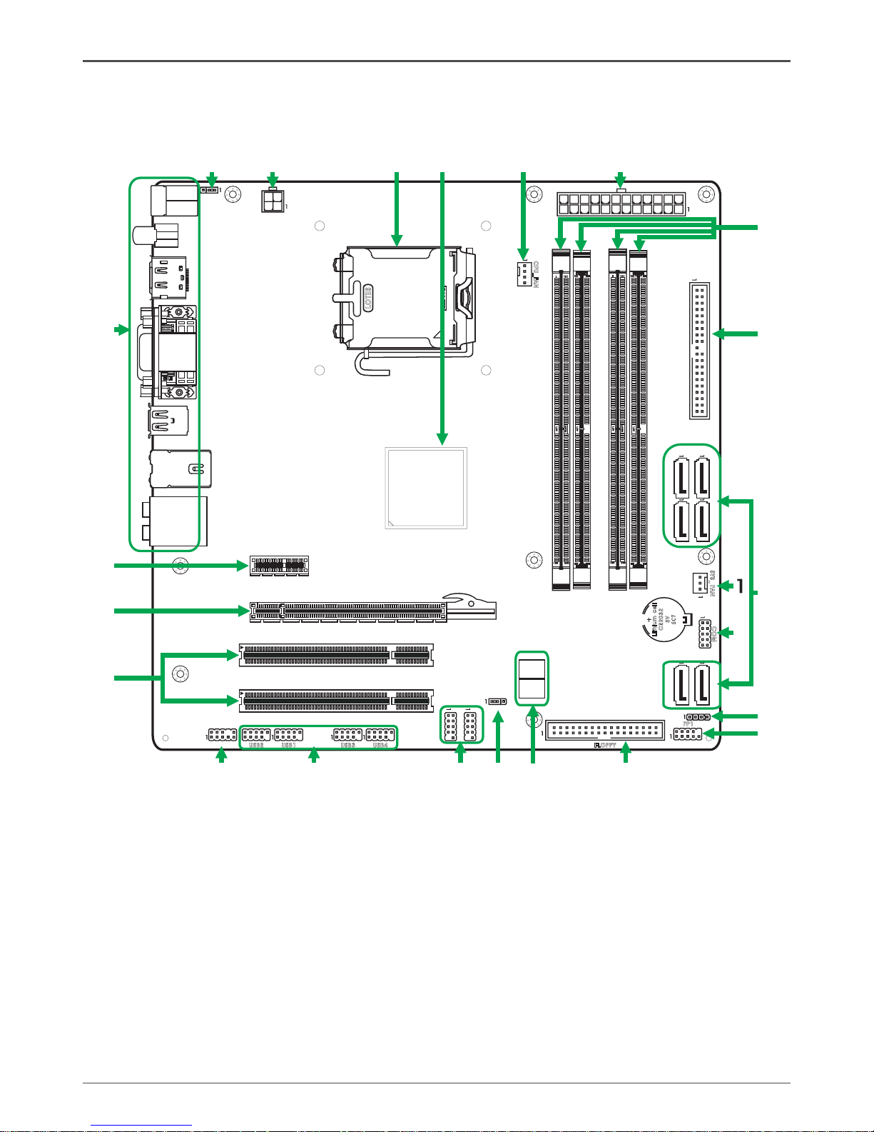
Figure 1 shows the motherboard and Figures 2 shows the back panel connectors.
Motherboard Layout
Figure 1. Board Layout
1. System Fan Connector
2. COM Port Header
3. Serial-ATA (SATA) Connectors
4. Speaker Header
5. Front Panel Header
6. Floppy Disk Drive Connector
7. Debug Display
8. Clear CMOS Jumper
9. IEEE1394 Header(Optional)
10. USB Headers
11. Front Audio Header
12. PCI Slots
13. PCI Express x16 Slot
14. PCI Express x1 Slot(Optional)
15. Backpanel Connectors
16. PS2 Power Select
17. 4-pin ATX_12V Power Connector
18. CPU Socket
19. Chipset
20. CPU Fan Connector
21. 24-pin ATX Power Connector
22. DDRII DIMM Sockets
23. IDE Connector
LO
TES
RE O EVM
120
240
121
DDR II3
DDR II1
DDR II4
DDR II2
CN
1
S
ATA
5
-
S
ATA
6
-
S
ATA
3
-
S
ATA
4
-
SA
TA
1
-
SA
TA
2
-
CO
M
SYS _
FA
N
CPU _FAN
FP
1
SPK 1
FLOP PY
Lit hium c ell
CR2 032
3V
SC 7
USB 4
139 4
139 4
USB 3
USB 1
USB 2
F Au dio_
PCI 1
PCI 2
PCI Expre ss 2 0.
PCI E2
120
240
121
PW2
PW1
JP2
JP1
KBM
S
SPD I
F
HDM
I D
P
/
DV
I V
GA
/
US
B
LA
N U
SB
/
HD
A
3
4
5
6
7
8
9
10
11
12
13
14
15
16
17
18
Chi pse t
2
20
22
23
19
D66
D67
21
8
GeForce 9300/9400 Series Motherboard
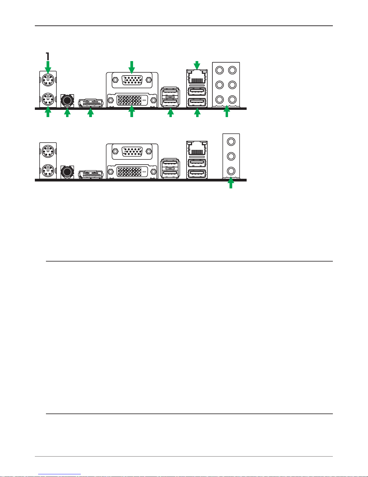
7. Port 2-Channel 4-Channel 6-Channel 8-Channel
Blue Line-In Line-In Line-In Line-In
Green Line-Out Front Speaker Out Front Speaker Out Front Speaker Out
Pink Mic In Mic In Mic In Mic In
Orange -- -- Center/Subwoofer Center/Subwoofer
Black -- Rear Speaker Out Rear Speaker Out Rear Speaker Out
Grey -- -- -- Side Speaker Out
8. LAN Connector
Lan Port with LEDs to indicate status.
· Yellow/Light Up/Blink = 10 Mbps/Link/Activity
· Yellow and Green/Light Up/Blink = 100 Mbps/link/Activity
· Yellow and Orange/Light Up/Blink = 1000 Mbps/link/Activity
9. VGA Port
10. Port 2-Channel 4-Channel 6-Channe
Blue Line-In Rear Speaker Out Rear Speaker Out
Green Line-Out Front Speaker Out Front Speaker Out
Pink Mic In Mic In Center/Subwoofer
Figure 2: Backpanel connectors
6
11
5
10
15
2
3
4 5 6 7
8
9
6
1. PS/2 Mouse Port
2. PS/2 Keyboard Port
3. SPDIF Out
4. HDMI/DP Port
5. DVI Connector
6. USB Connectors
6
11
5
10
15
10

9
Hardware Installation
This section will guide you through the installation of the motherboard. The topics
covered in this section are:
q Preparing the motherboard
v Installing the CPU
v Installing the CPU fan
v Installing the memory
q Installing the motherboard
q Connecting cables and setting switches
Safety Instructions
To reduce the risk of re, electric shock, and injury, always follow basic safety precations.
Remember to remove power from your computer by disconnecting the AC main source
before removing or installing any equipment from/to the computer chassis.
Hardware Installation
10
GeForce 9300/9400 Series Motherboard
Preparing the Motherboard
The motherboard shipped in the box does not contain a CPU and memory. You need
to purchase these to complete this installation.
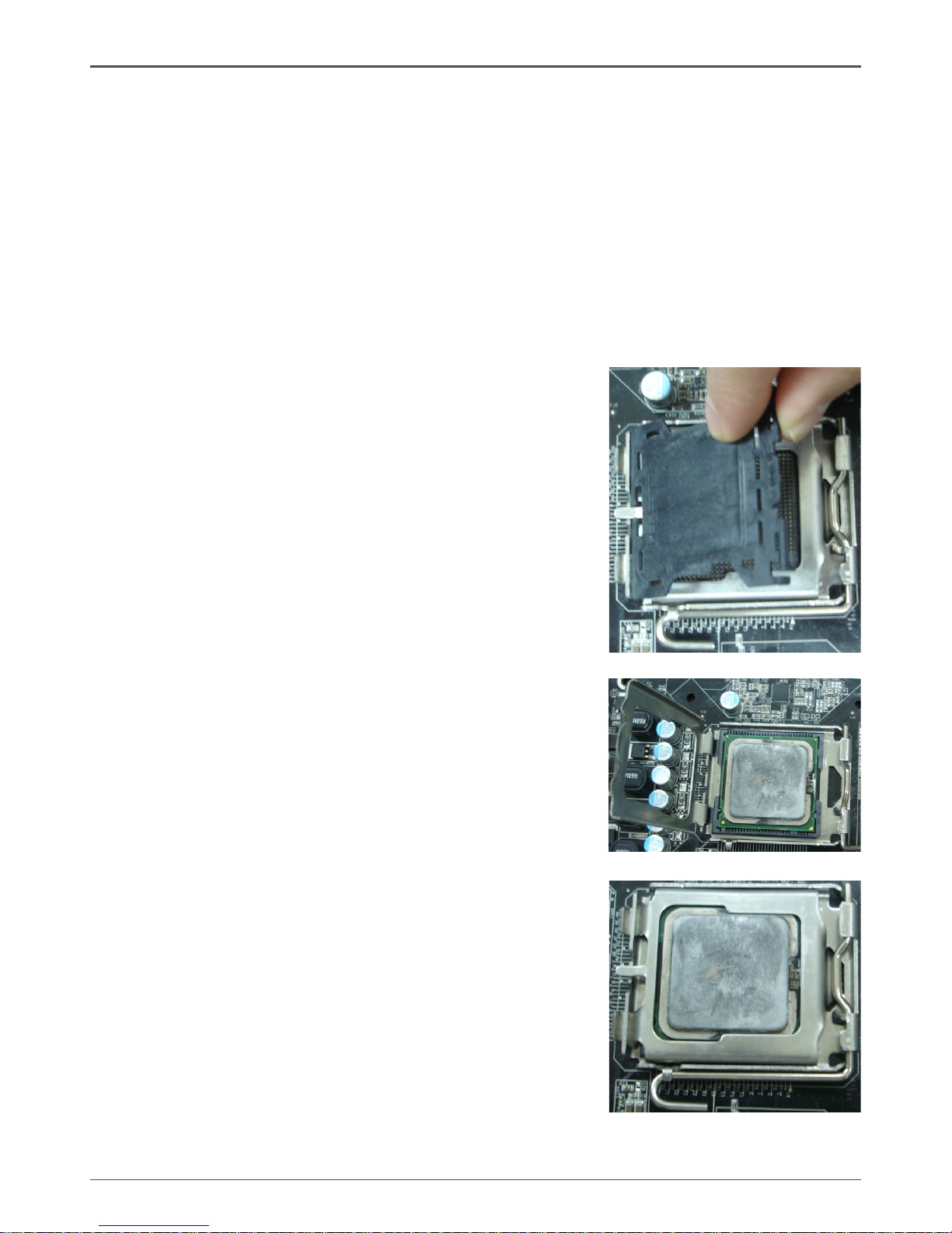
Installing the CPU
Be very careful when handling the CPU. Make sure not to bend or break any pins on
the back. Hold the processor only by the edges and do not touch the bottom of the
processor.
Use the following procedure to install the CPU onto the motherboard.
1. Unhook the socket lever by pushing down and
away from the socket.
2. Lift the load plate. There is a protective socket
cover on the load plate to protect the socket
when there is no CPU installed.
3. Remove the protective socket cover from the
load plate.
4. Remove the processor from its protective cover,
making sure you hold it only by the edges.
It is a good idea to save the cover so that
whenever you remove the CPU, you have a
safe place to store it.
5. Align the notches in the processor with the
notches on the socket.
6. Lower the processor straight down into the
socket with out tilting or sliding it into the socket.
Note: Make sure the CPU is fully seated and
level in the socket.
7. Close the load plate over the CPU and press
down while you close and engage the socket
lever.

11
120
240
121
Lith ium cel l
CR20 32
3V
SC 7
120
240
121
LO
TES
RE O EVM
Installing the CPU Fan
There are many different fan types that can be used with this motherboard. Follow the
instruction that came with your fan assembly. Be sure that the fan orientation is correct
for your chassis type and your fan assembly.
Installing Memory DIMMs
Your new motherboard has four 1.8V 240-pin slots for DDR2 memory. These slots
support 256 Mb, 512 Mb, 1Gb and 2Gb DDR2 technologies. There must be at least
one memory bank populated to ensure normal operation. Use the following the recommendations for installing memory. (See Figure 1 on page 7 for the location of the
memory slots.)
q One DIMM: You can install the DIMM into any slot.
q Two DIMMs: Install into slots 1 and 2, or install into slots 3 and 4. The idea is
to run on dual channel mode.
q Four DIMMs: Install into slots 1,2, 3 and 4. The idea is to run on dual channel
mode.
Hardware Installation
DDRII-4
DDRII-2
DDRII-3
DDRII-1

12
GeForce 9300/9400 Series Motherboard
Use the following procedure to install memory DIMMs into the slots on the motherboard. Note that there is only one gap near the center of the DIMM slot. This slot
matches the slot on the memory DIMM to ensure the component is installed properly.
1. Unlock a DIMM slot by pressing the module clips outward.
2. Align the memory module to the DIMM slot, and insert the module vertically into
the DIMM slot. The plastic clips at both sides of the DIMM slot automatically lock
the DIMM into the connector.
Installing the Motherboard
The sequence of installing the motherboard into the chassis depends on the chassis
you are using and if you are replacing an existing motherboard or working with an
empty chassis. Determine if it would be easier to make all the connections prior to this
step or to secure the motherboard and then make all the connections. It is normally
easier to secure the motherboard rst.
Use the following procedure to install the I/O shield and secure the motherboard into
the chassis.
Note: Be sure that the CPU fan assembly has enough clearance for the
chassis covers to lock into place and for the expansion cards. Also
make sure the CPU Fan assembly is aligned with the vents on the
covers.
Installing the I/O Shield
The motherboard kit comes with an I/O shield that is used to block radio frequency
transmissions, protects internal components from dust and foreign objects, and
promotes correct airow within the chassis.
Before installing the motherboard, install the I/O shield from the inside of the chassis.
Press the I/O shield into place and make sure it ts securely. If the I/O shield does
not t into the chassis, you would need to obtain the proper size from the chassis
supplier.

13
Connecting Cables and Setting Switches
This section takes you through all the connections and switch settings necessary on
the motherboard. This will include:
q Power Connections
v 24-pin ATX power (PW1)
v 4-pin ATX 12V power (PW2)
q Internal Headers
v Hard Disk Connector - IDE
v SPK Header
v Serial Port Header - COM
v IEEE 1394 Header(Optional)
v Front panel header
v USB Headers
v Floppy Disk Drive Connector - FDD
v F_Audio Header
q Serial ATA II
q Chassis Fans
q Expansion slots
q Jumper settings
See Figure 1 to locate the connectors and jumpers referenced in the following
procedure.
Hardware Installation
14
GeForce 9300/9400 Series Motherboard
Connecting Internal Headers
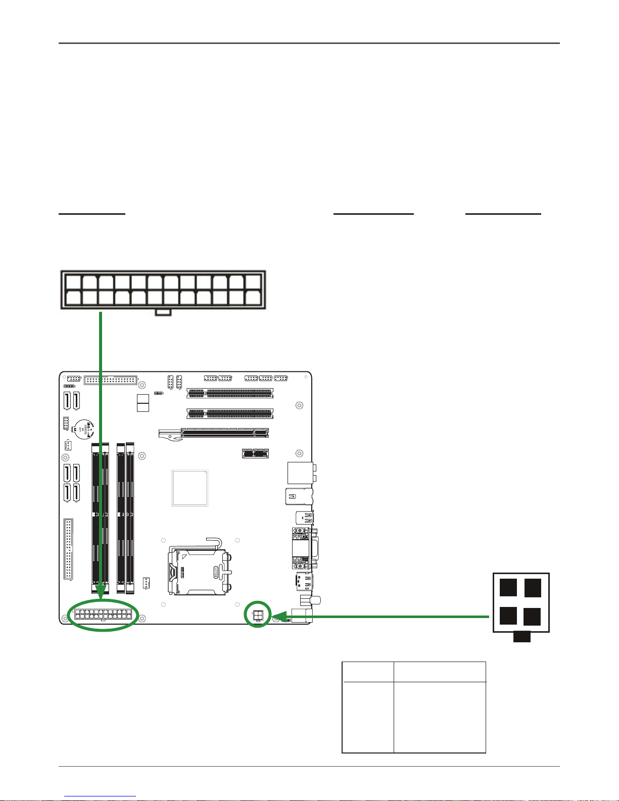
24-pin ATX Power (PW1)
PW1 is the main power supply connector located along the edge of the board next to
the DIMM slots. Make sure that the power supply cable and pins are properly aligned
with the connector on the motherboard. Firmly plug the power supply cable into the
connector and make sure it is secure.
Table 1. PW1 Pin Assignments
Connector Pin Signal Pin Signal
1 +3.3V 13 +3.3V
2 +3.3V 14 -12V
3 GND 15 GND
4 +5V 16 PS_ON
5 GND 17 GND
6 +5V 18 GND
7 GND 19 GND
8 PWROK 20 -5V
9 +5V_AUX 21 +5V
10 +12V 22 +5V
11 +12V 23 +5V
12 +3.3V 24 GND
120
240
121
Lithi um c ell
CR203 2
3V
SC7
120
240
121
LO
TES
RE O EVM
1
12
13
24
4-pin ATX 12V Power (PW2)
PW2, the 4-pin ATX 12V power connection,
is used to provide power to the CPU. Align
the pins to the connector and press rmly
until seated.
1
2
3
4
PIN Assignment
1 GND
2 GND
3 +12V
4 +12V
PW2 - Pin Denition

15
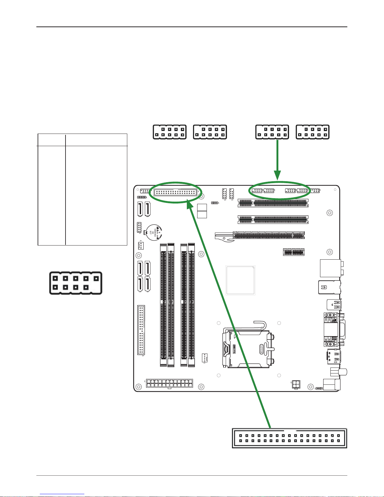
Hard Disk Connector - IDE
The motherboard has a 32-bit Enhanced PCI IDE and Ultra DMA 66/100/133 controller that provides PIO mode 0~4, Bus Master, and Ultra DMA 66/100/133 function. You
can connect up to two hard disk drives, CD-ROM, 120MB Floppy (reserved for future
BIOS) and other devices.
1
120
240
121
Lith ium c ell
CR20 32
3V
SC7
120
240
121
LO
TES
RE O EVM
PIN Assignment
1 VCC
2 NC
3 NC
4 SPK-
SPK - Pin Denition
Hardware Installation
SPK Header
SPK
1
16
GeForce 9300/9400 Series Motherboard
120
240
121
Lithi um cell
CR203 2
3V
SC7
120
240
121
LO
TES
RE O EVM
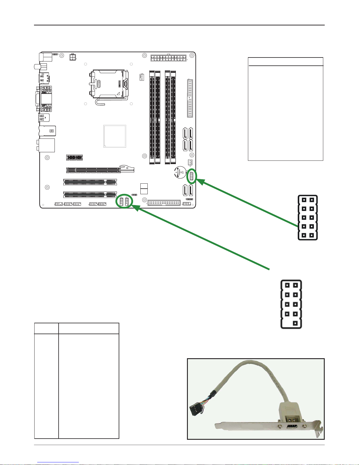
IEEE 1394 Header(Optional)
The motherboard provides two 1394 pin
headers that allow you to connect IEEE 1394
ports.
Serial Port Header - COM
COM
COM - Pin Denition
PIN Assignment
1 DCD
2 RXD
3 TXD
4 DTR
5 GND
6 DSR
7 RTS
8 CTS
9 RI
10 NC
IEEE 1394 Pin Denition
PIN Assignment
1 TPA+
2 TPA-
3 Ground
4 Ground
5 TPB+
6 TPB-
7 Cable power
8 Cable power
9 Key (no pin)
10 Ground
1
2
9
10
1 9
102
IEEE 1394

17
120
240
121
Lith ium c ell
CR20 32
3V
SC7
120
240
121
LO
TES
RE O EVM
Front panel header
The front panel header on this motherboard is one connector used
to connect the following four cables (see Table 2 for pin denitions):
q PWRLED
Attach the front panel power LED cable to these two pins of the connector. The
Power LED indicates the system’s status.
Note: Some chassis do not have all four cables. Be sure to match the name on
the connectors to the corresponding pins.
q PWR SW
Attach the power button cable from the case to these two pins. Pressing the
power button on the front panel turns the system on and off rather than using the
power supply button.
q HDD LED
Attach the hard disk drive indicator LED cable to these two pins. The HDD
indicator LED indicates the activity status of the hard disks.
q RST SW
Attach the Reset switch cable from the front panel of the case to these two pins.
The system restarts when the RESET switch is pressed.
RESET
GND
HDD_LED-
HDD_LED+
FP1
NC
PWR_SW
KEY
PW_LED+
7
9
5
3
1
6
8
10
2
4
GND
PW_LED-
Front Panel Header
Pin Denition
18
GeForce 9300/9400 Series Motherboard
120
240
121
Lith ium c ell
CR20 32
3V
SC7
120
240
121
LO
TES
RE O EVM
PIN Assignment
1 VCC
2 VCC
3 USBP04 USBP15 USBP0+
6 USBP1+
7 GND
8 GND
9 KEY
10 OC#
USB Pin Denition
USB Headers
This motherboard contains four USB 2.0 ports that are exposed on the rear panel of
the chassis(Figure 2). The motherboard also contains four 10-pin internal header connectors onboard.
1. Secure the bracket to either the front or rear panel of your chassis (not all chassis
are equipped with the front panel option).
Hardware Installation
1 9
102
USB2USB1USB3USB4
The motherboard provides a standard oppy disk
drive connector that supports 360K, 720K, 1.2M,
1.44M and 2.88M oppy disk types.
Floppy Disk Drive Connector - FDD
19
120
240
121
Lith ium c ell
CR20 32
3V
SC7
120
240
121
LO
TES
RE O EVM
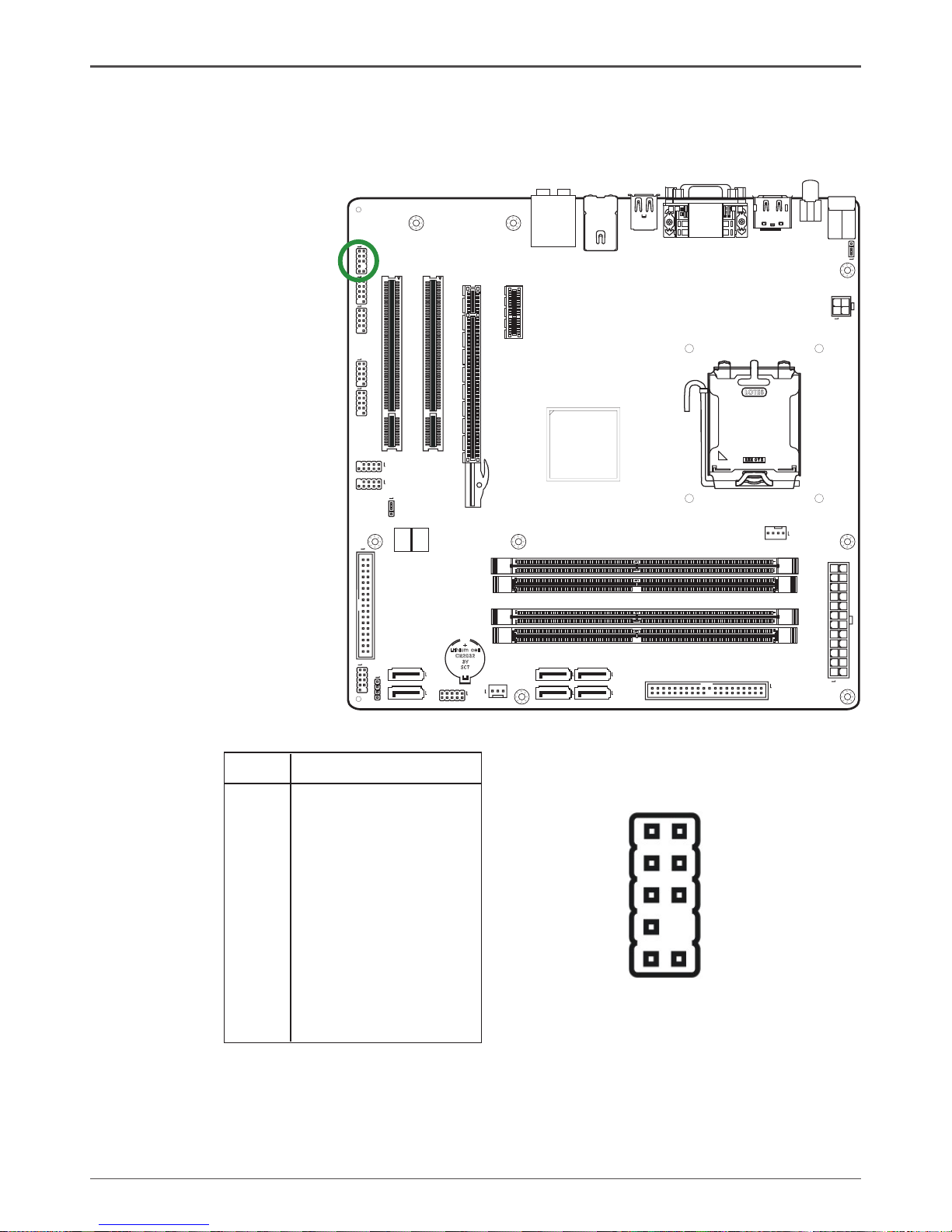
F_Audio Header
The audio connector supports HD audio standard and provides two kinds of audio
output choices: the Front Audio, the Rear Audio. The front Audio supports re-tasking
function.
Note:
In order to utilize the front audio header, your chassis must have front audio connector.
Also please make sure the pin assignment on the cable is the same as the pin assignment
on the mainboard header. To nd out if the chassis you are buying supports a front audio
connector, please contract your dealer.
PIN Assignment
1 MIC2(L)
2 GND
3 MIC(R)
4 -ACZ-DET
5 Front Audio(R)
6 Reserved
7 FAVDIO - JD
8 Key (No pin)
9 Front Audio(L)
10 Reserved
F_Audio Pin Denition
2
1
10
9
20
GeForce 9300/9400 Series Motherboard
120
240
121
Lith ium c ell
CR20 32
3V
SC7
120
240
121
LO
TES
RE O EVM
PIN SIGNAL
1 GND
2 TXP
3 TXN
4 GND
5 RXN
6 RXP
7 GND
SATA-1~SATA-6-
Pin Denition
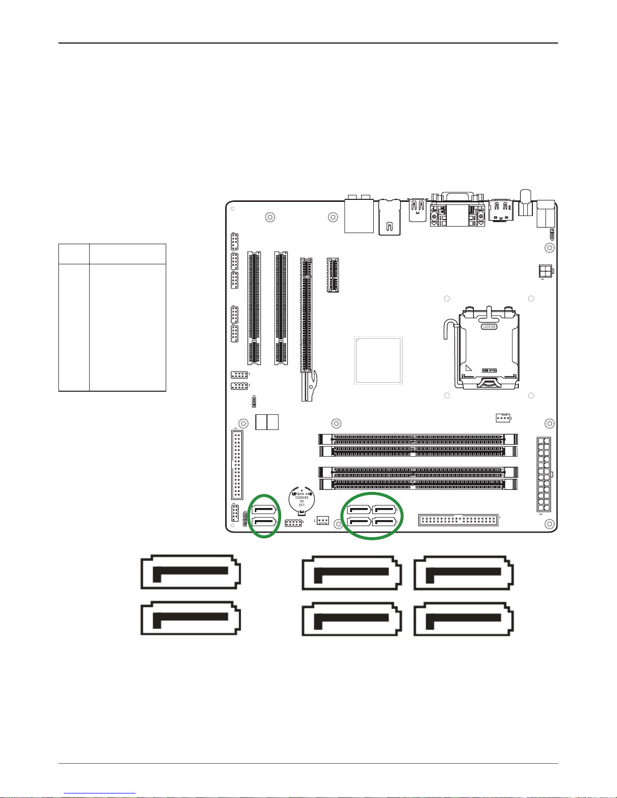
Connecting Serial ATA Cables(SATA-1~SATA-6 Optional)
The Serial ATA II connector is used to connect the Serial ATA II device to the
motherboard. These connectors support the thin Serial ATA II cables for primary
storage devices. The current Serial ATA II interface allows up to 3Gb/s data transfer
rate.
There are six serial ATA connectors on the motherboard that support AHCI and RAID
congurations.
Hardware Installation
SATA-2
SATA-1
SATA-4
SATA-3
SATA-6
SATA-5
1
1
1
1
1
1
 Loading...