

Page 1
Page 2

1
Federal Communications Commission (FCC) Statement
This equipment has been tested and found to comply with the limits for a Class B digital device,
pursuant to Part 15 of FCC Rules. These limits are designed to provide reasonable protection
against harmful interference in a residential installation. This equipment generates, uses and
can radiate radio frequency energy and, if not installed and used in accordance with instructions
contained in this manual, may cause harmful interference to radio and television communications.
However, there is no guarantee that interference will not occur in a particular installation.
If this equipment does cause harmful interference to radio or television reception, which can
be determined by turning the equipment off and on, the user is encouraged to try to correct the
interference by one or more of the following measures:
- REORIENT OR RELOCATE THE RECEIVING ANTENNA
- INCREASE THE SEPARATION BETWEEN THE EQUIPMENT AND THE RECEIVER
- CONNECT THE EQUIPMENT INTO AN OUTLET ON A CIRCUIT DIFFERENT FROM
THAT OF THE RECEIVER
- CONSULT THE DEALER OR AN EXPERIENCED AUDIO/TELEVISION TECHNICIAN
NOTE:
Connecting this device to peripheral devices that do not comply with Class B requirements, or
using an unshielded peripheral data cable, could also result in harmful interference to radio or
television reception.
The user is cautioned that any changes or modifications not expressly approved by the party
responsible for compliance could void the user’s authority to operate this equipment.
To ensure that the use of this product does not contribute to interference, it is necessary to use
shielded I/O cables.
Copyright
This manual is copyrighted with all rights reserved. No portion of this manual may be copied or
reproduced by any means.
While every precaution has been taken in the preparation of this manual, no responsibility for
errors or omissions is assumed. Neither is any liability assumed for damages resulting from the
use of the information contained herein.
Trademarks
All brand names, logos and registered trademarks mentioned are property of their respective
owners.
Electronic Emission Notices
WARNING!
Page 3

2
GeForce 9300/9400 ITX Series Motherboard
Table of Contents
Motherboard Specifications ------------------------------------------------------------------- 4
Motherboard Layout------------------------------------------------------------------------------ 6
Hardware Installation ---------------------------------------------------------------------------- 8
Safety Instructions ----------------------------------------------------------------------------- 8
Preparing the Motherboard -------------------------------------------------------------------- 9
Installing the CPU ------------------------------------------------------------------------------ 9
Installing the CPU Fan ------------------------------------------------------------------------ 10
Installing Memory DIMMs -------------------------------------------------------------------- 10
Installing the Motherboard ------------------------------------------------------------------- 11
Installing the I/O Shield ----------------------------------------------------------------------- 11
Connecting Cables and Setting Switches ------------------------------------------------ 12
24-pin ATX Power (PW1) --------------------------------------------------------------------- 13
4-pin ATX 12V Power (PW2) ---------------------------------------------------------------- 13
SPK Header* ------------------------------------------------------------------------------------ 14
serial Port Header - COM -------------------------------------------------------------------- 14
USB Headers------------------------------------------------------------------------------------ 14
Front Panel Header ---------------------------------------------------------------------------- 15
F_Audio Header -------------------------------------------------------------------------------- 16
SPDIF-Out Header* --------------------------------------------------------------------------- 16
Connecting Serial ATA Cables* ------------------------------------------------------------- 17
Fan Connections ------------------------------------------------------------------------------- 17
Expansion Slots -------------------------------------------------------------------------------- 18
PCI Express x16 Slots ------------------------------------------------------------------------ 18
Jumper Settings* ------------------------------------------------------------------------------- 19
Configuring the BIOS ---------------------------------------------------------------------------- 20
Enter BIOS Setup ----------------------------------------------------------------------------------- 20
Main Menu -------------------------------------------------------------------------------------- 21
Standard CMOS Features Menu --------------------------------------------------------- 22
Date and Time ------------------------------------------------------------------------------ 23
IDE Channel --------------------------------------------------------------------------------- 23
Video ------------------------------------------------------------------------------------------ 23
Drive A ---------------------------------------------------------------------------------------- 23
Halt On---------------------------------------------------------------------------------------- 23
Memory --------------------------------------------------------------------------------------- 24
Advanced BIOS Features ------------------------------------------------------------------ 24
CPU Features ---------------------------------------------------------------------------------- 25
Hard Disk Boot Priority -------------------------------------------------------------------- 26
Advanced Chipset Features -------------------------------------------------------------- 28
Integrated Peripherals Menu ------------------------------------------------------------- 29
Page 4

3
Table of Contents
Power Management Setup Menu ------------------------------------------------------- 30
PnP/PCI Configuration --------------------------------------------------------------------- 31
Frequency/Voltage Control --------------------------------------------------------------- 33
Load Optimized Defaults ------------------------------------------------------------------ 35
Set Supervisor/User Password ---------------------------------------------------------- 36
Save & Exit Setup ---------------------------------------------------------------------------- 37
Exit Without Saving ------------------------------------------------------------------------- 37
Flash Update Procedure ------------------------------------------------------------------ 38
Installing Drivers and Software -------------------------------------------------------------- 39
Drivers Installation ------------------------------------------------------------------------------- 40
HDMI SETUP --------------------------------------------------------------------------------------- 44
REALTEK HD AUDIO DRIVER SETUP ----------------------------------------------------- 45
Getting Started ---------------------------------------------------------------------------------- 45
Sound Effect ------------------------------------------------------------------------------------- 45
Environment Simulation ---------------------------------------------------------------------- 45
Equalizer Selection --------------------------------------------------------------------------- 46
Frequently Used Equalizer Setting -------------------------------------------------------- 46
Karaoke Mode ---------------------------------------------------------------------------------- 46
Mixer----------------------------------------------------------------------------------------------- 47
Playback control --------------------------------------------------------------------------- 47
Recording control -------------------------------------------------------------------------- 48
Audio I/O ------------------------------------------------------------------------------------- 49
Speaker Configuration ------------------------------------------------------------------- 50
Connector Settings ------------------------------------------------------------------------ 51
S/PDIF --------------------------------------------------------------------------------------- 51
Speaker Calibration ----------------------------------------------------------------------- 52
Microphone---------------------------------------------------------------------------------- 53
Noise Suppression ------------------------------------------------------------------------ 53
Beam Forming ----------------------------------------------------------------------------- 53
Acoustic Echo Cancellation ------------------------------------------------------------- 53
Audio Demo --------------------------------------------------------------------------------- 54
Information --------------------------------------------------------------------------------- 54
SATA RAID User Manual ------------------------------------------------------------------------ 55
Setting up the BIOS --------------------------------------------------------------------------- 55
Entering the RAID BIOS Setup ------------------------------------------------------------- 57
Installing the RAID Drives -------------------------------------------------------------------- 60
Hybrid SLI Technology -------------------------------------------------------------------------- 63
Precaution : Intel CPU Cooling Fan Installation ---------------------------------------- 76
Page 5

4
GeForce 9300/9400 ITX Series Motherboard
Motherboard Specications
q Chipset
v NVIDIA MCP7A Series
q Size
v mini ITX form factor of 6.7 inch x 6.7 inch
q Microprocessor support
v Intel LGA 775 Celeron® , Pentium® 4, Pentium® D, Core
TM
2 Series
v Support for 400MT/s to 1333MT/s (100MHz to 333MHz FSB)
q Operating systems:
v Supports Windows XP 32bit/64bit and Windows Vista 32bit/64bit
q System Memory support
v Supports DDRII667/800. Supports up to 8GBs DDRII memory.
v Supports dual Channel DDR2 128-Bit Memory Interface
q USB 2.0 Ports
v Supports hot plug and play
v Twelve USB 2.0 ports (six rear panel ports, six from onboard USB headers)
v Supports USB 2.0 protocol up to 480 Mbps transmission rate
v Support USB wake up from S3 (PCB Ver:03,04)
q Onboard Serial ATA II
v Two SATA II ports / three SATA II ports(PCB Ver:03,04).
v Independent DMA operation.
v Data transfer rates of 3Gb/s.
q On board RTL8211CL Gigabit LAN(Optional)
v Supports 10/100/1000M bps operation
q On board RTL8201EL Fast Ethernet(Optional)
v Supports 10/100Mbps operation
v Supports half/full duplex operation
q Onboard Audio(Optional)
v Azalia High-Definition audio
v Supports 6-channel
v Supports Jack-Sensing function
q Green Function
v Supports ACPI (Advanced Configuration and Power Interface)
v RTC timer to power-on the system
v AC power failure recovery
q Onboard Graphics support
v Integrated 300MHz DAC for analog displays with resolutions up to 1920x1440
at 75Hz.
Page 6

5
Motherboard Specifications
v Support Hybrid SLI to increase graphics performance with GeForce® Boost
v Integrated GeForce 9xxx Series GPU,Supports DX10
v VGA / DVI-D / HDMI output support(optional)
q PCI Express Interface
v PCI Express Generation 2.0 compatible
v 5 GHz support, for a total bandwidth of 5 Gbps per direction per lane
v Wake up function is supported
v Clock spread spectrum capability.
q Integrated HDMI Interface with HDCP
v Support Dual link DVI,resolutions up to 2560x1600 (PCB Ver:03,04)
v Support Single link DVI,resolutions up to 1920x1440 (PCB Ver:00,01 only)
v Supports DVI or HDMI 1.3 interfaces
v Secure digital audio merged from integrated HDA codec with no external audio
signals required
v Support for HDCP 1.3 using soft or hard HDCP keys
v HDCP encryption support when configured as DVI or HDMI link without the
need for external HDCP key crypto ROM
q Dual Head Display Controller
v Full NVIDIA nView™ multi-display technology capability, with independent
display controllers for the CRT, TMDS, DisplayPort, and HDMI interface
v Each controller can drive same or different display contents to different resolu tions and refresh rates
q Expansion Slots
v One PCI Express x16 slot.
Page 7
6
GeForce 9300/9400 ITX Series Motherboard
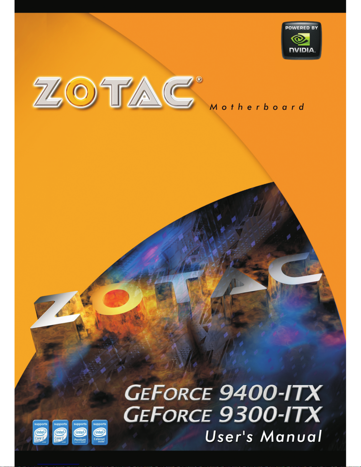
Motherboard Layout
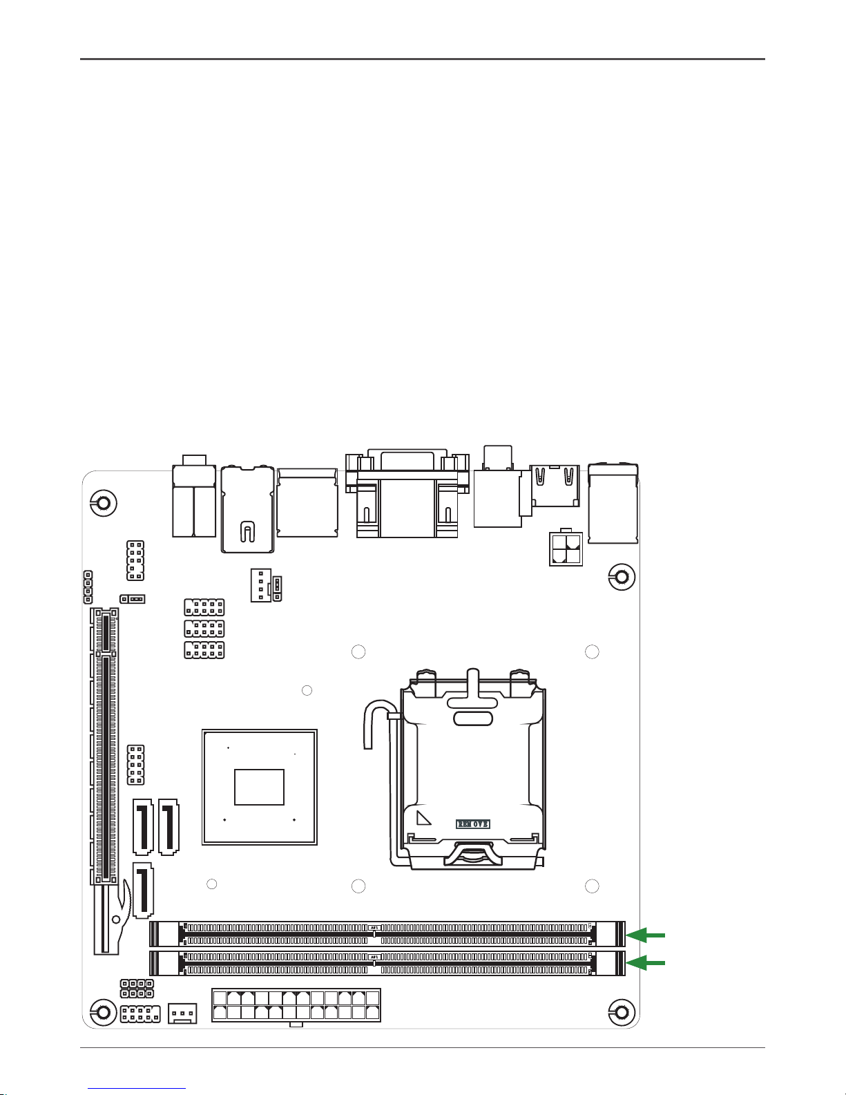
Figure 1 shows the motherboard and Figure 2 shows the back panel connectors.
Figure 1. Board Layout
120
240
121
120
240
121
LO
TES
R E O EVM
+
Chiset
DDRII1
DDRII2
PW
1
S F
AN
1
_
FP
1
SATA1
SATA2
COM
PCIEX16
SPK1
C F AN 1_
FP S1_
FP
U2
_
FP
U1
_
FP
U3
_
JP1
PW
2
HDM
I
DV
I V
GA
/
eS
ATA
US
B
/
LA
N U
SB
/
SD1
Ke
yboard
US
B
/
SPDIF
OUT
-
2
3
9
10
11
12
13
14
15
16
S
PK1
17
SATA3(PC B Ver:03,04)
18
JP2(PCB Ver:03,04 )
(PCB Ver :0 0 o nl y)
(PCB
Ve
r:01,03,0 4)
SPDI
F
(PCP
Ve
r:
04
only
)
19
24-pin ATX Power Connector
System Fan Connector
Front Panel Header
Speaker Header(PCB Ver:01,03,04)*
SPDIF-out(PCB Ver:04)*
Serial-ATA (SATA) Connectors(SATA3 for PCB
ver:03,04)*
COM Header
Speaker Header(PCB Ver:00 only)
*
PCI Express x16 Slot
1.
2.
3.
4.
5.
6.
7.
8.
9.
Clear CMOS Jumper
Front Audio Header
Backpanel Connectors
4-pin ATX_12V Power Connector
CPU Fan Connector
USB Power Select Jumper(PCB Ver:03,04)
*
USB / WiFi Headers
CPU Socket
Chipset
DDRII DIMM Sockets
10.
11.
12.
13.
14.
15.
16.
17.
18.
19.
Page 8
7
236
D
A105
0J00F
- -
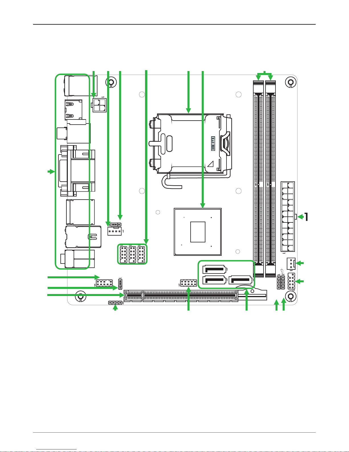
Rear Panel
7. Port 2-Channel 4-Channel 6-Channel
Blue Line-In Rear Speaker Out Rear Speaker Out
Green Line-Out Front Speaker Out Front Speaker Out
Pink Mic In Mic In Center/Subwoofer
8. LAN Connector
Lan Port with LEDs to indicate status.
· Yellow/Light Up/Blink = 10 Mbps/Link/Activity
· Yellow and Orange/Light Up/Blink = 100 Mbps/link/Activity
· Yellow and Orange/Light Up/Blink = 1000 Mbps/link/Activity
9. VGA Port
Figure 2: Backpanel connectors
1. PS/2 keyboard connector
2. USB Connectors
3. HDMI Port
4. SPDIF Out(Coaxial / Optical)
5. DVI Connector(Support DVI-D)
6. eSATA Connector(For Motherboard PCB Ver00:AHCI mode only)*
6
11
5
10
15
72 2
3
4
5
6
8
9
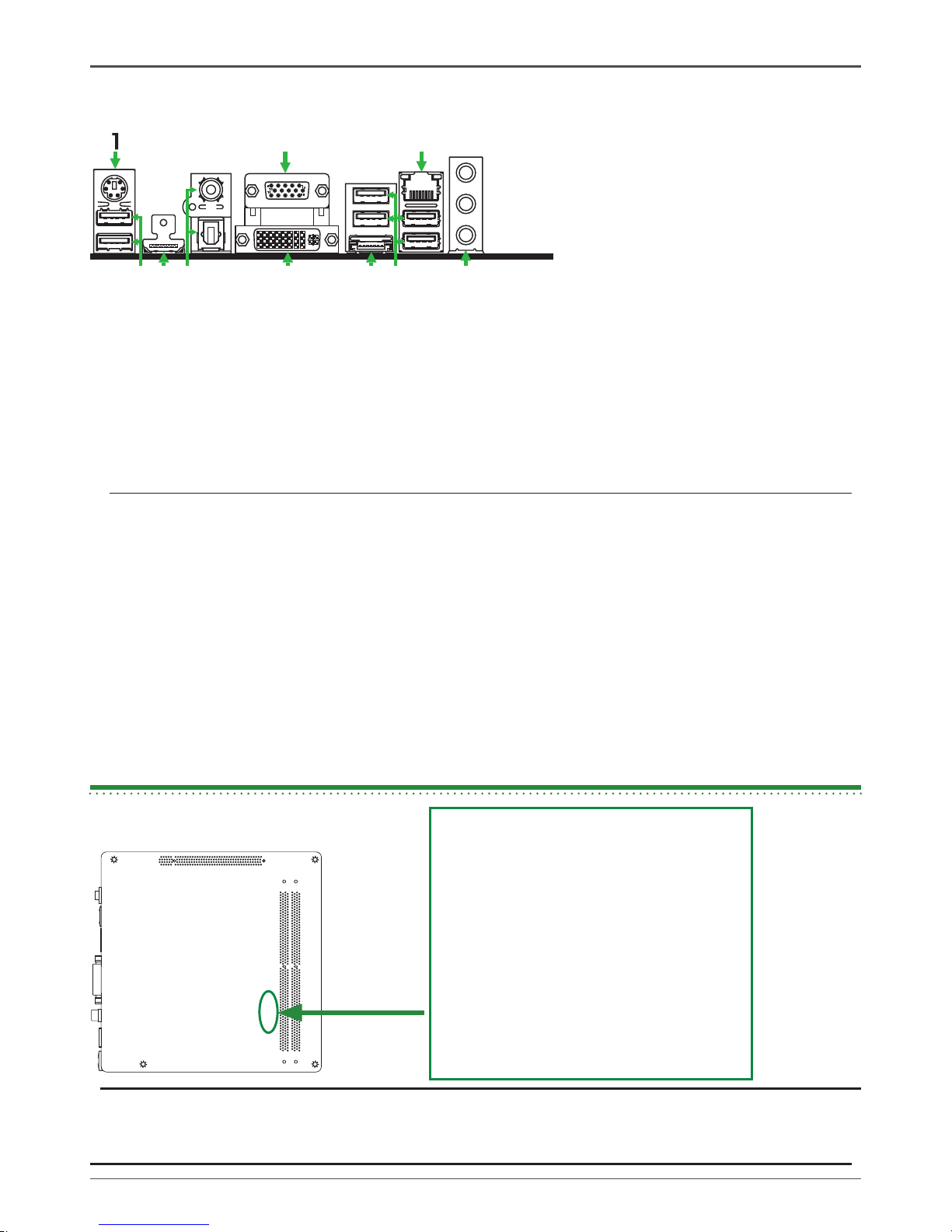
The bottom side of motherboard PCB
shows “236-DA105-xx00F”
Motherboard PCB Version:00
The bottom side of motherboard PCB
shows “236-DA105-xx10F”
Motherboard PCB Version:01
The bottom side of motherboard PCB
shows “236-DA105-xx30F”
Motherboard PCB Version:03
The bottom side of motherboard PCB
shows “236-DA105-xx40F”
Motherboard PCB Version:04
Note:
* Different motherboard PCB version could carry slightly different features and components
placement . Please refer to the following diagram to identify PCB version:
* How to identify PCB Versionto identify PCB Version PCB Version
Page 9

8
GeForce 9300/9400 ITX Series Motherboard
Hardware Installation
This section will guide you through the installation of the motherboard. The topics
covered in this section are:
q Preparing the motherboard
v Installing the CPU
v Installing the CPU fan
v Installing the memory
q Installing the motherboard
q Connecting cables and setting switches
Safety Instructions
To reduce the risk of fire, electric shock, and injury, always follow basic safety precations.
Remember to remove power from your computer by disconnecting the AC main source
before removing or installing any equipment from/to the computer chassis.
Page 10
9
Hardware Installation
Preparing the Motherboard
The motherboard shipped in the box does not contain a CPU and memory. You need
to purchase these to complete this installation.
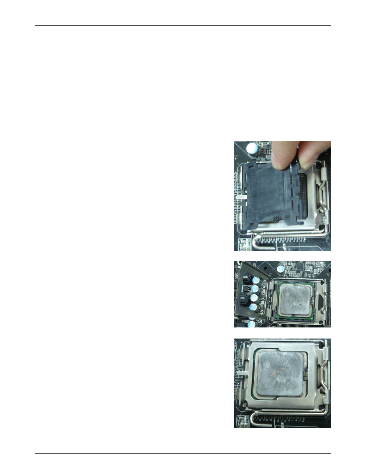
Installing the CPU
Be very careful when handling the CPU. Make sure not to bend or break any pins on
the back. Hold the processor only by the edges and do not touch the bottom of the
processor.
Use the following procedure to install the CPU onto the motherboard.
1. Unhook the socket lever by pushing down and
away from the socket.
2. Lift the load plate. There is a protective socket
cover on the load plate to protect the socket
when there is no CPU installed.
3. Remove the protective socket cover from the
load plate.
4. Remove the processor from its protective cover,
making sure you hold it only by the edges.
It is a good idea to save the cover so that
whenever you remove the CPU, you have a
safe place to store it.
5. Align the notches in the processor with the
notches on the socket.
6. Lower the processor straight down into the
socket with out tilting or sliding it into the socket.
Note: Make sure the CPU is fully seated and
level in the socket.
7. Close the load plate over the CPU and press
down while you close and engage the socket
lever.
Page 11
10
GeForce 9300/9400 ITX Series Motherboard
120
240
121
120
240
121
LO
TE S
R E O EVM
+
Installing the CPU Fan
There are many different fan types that can be used with this motherboard. Follow the
instruction that came with your fan assembly. Be sure that the fan orientation is correct
for your chassis type and your fan assembly.
Installing Memory DIMMs
Your new motherboard has two 1.8V 240-pin slots for DDR2 memory. These slots
support 256 MB, 512 Mb, 1GB / 2GB / 4GB DDR2 technologies. There must be at
least one memory bank populated to ensure normal operation. Use the following the
recommendations for installing memory. (See Figure 1 for the location of the memory
slots.)
q One DIMM: You can install the DIMM into any slot.
q Two DIMMs: Install into slots 1 and 2. The idea is to run on dual channel
mode.
DDRII-2
DDRII-1
Page 12

11
Hardware Installation
Use the following procedure to install memory DIMMs into the slots on the motherboard. Note that there is only one gap near the center of the DIMM slot. This slot
matches the slot on the memory DIMM to ensure the component is installed properly.
1. Unlock a DIMM slot by pressing the module clips outward.
2. Align the memory module to the DIMM slot, and insert the module vertically into
the DIMM slot. The plastic clips at both sides of the DIMM slot automatically lock
the DIMM into the connector.
Installing the Motherboard
The sequence of installing the motherboard into the chassis depends on the chassis
you are using and if you are replacing an existing motherboard or working with an
empty chassis. Determine if it would be easier to make all the connections prior to this
step or to secure the motherboard and then make all the connections. It is normally
easier to secure the motherboard first.
Use the following procedure to install the I/O shield and secure the motherboard into
the chassis.
Note: Be sure that the CPU fan assembly has enough clearance for the
chassis covers to lock into place and for the expansion cards. Also
make sure the CPU Fan assembly is aligned with the vents on the
covers.
Installing the I/O Shield
The motherboard kit comes with an I/O shield that is used to block radio frequency
transmissions, protects internal components from dust and foreign objects, and
promotes correct airflow within the chassis.
Before installing the motherboard, install the I/O shield from the inside of the chassis.
Press the I/O shield into place and make sure it fits securely. If the I/O shield does
not fit into the chassis, you would need to obtain the proper size from the chassis
supplier.
Page 13

12
GeForce 9300/9400 ITX Series Motherboard
Connecting Cables and Setting Switches
This section takes you through all the connections and switch settings necessary on
the motherboard. This will include:
q Power Connections
v 24-pin ATX power (PW1)
v 4-pin ATX 12V power (PW2)
q Internal Headers
v SPK Header*
v Serial Port Header - COM
v USB Headers
v Front panel header
v F_Audio Header
v SPDIF-Out Header*
q Chassis Fans
q Expansion slots
q Jumper settings*
See Figure 1 to locate the connectors and jumpers referenced in the following
procedure.
Page 14
13
Connecting Internal Headers
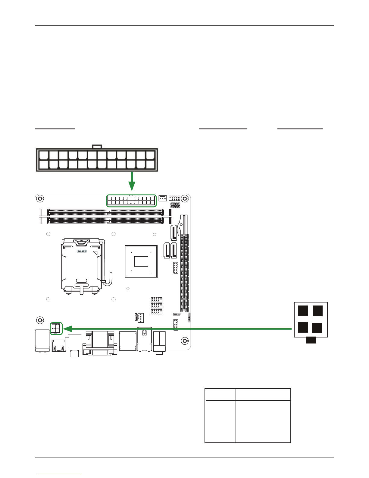
24-pin ATX Power (PW1)
PW1 is the main power supply connector located along the edge of the board next to
the DIMM slots. Make sure that the power supply cable and pins are properly aligned
with the connector on the motherboard. Firmly plug the power supply cable into the
connector and make sure it is secure.
Table 1. PW1 Pin Assignments
Connector Pin Signal Pin Signal
1 +3.3V 13 +3.3V
2 +3.3V 14 -12V
3 GND 15 GND
4 +5V 16 PS_ON
5 GND 17 GND
6 +5V 18 GND
7 GND 19 GND
8 PWROK 20 -5V
9 +5V_AUX 21 +5V
10 +12V 22 +5V
11 +12V 23 +5V
12 +3.3V 24 GND
120
240
121
120
240
121
LO
TES
RE O EVM
+
Hardware Installation
1
12
13
24
4-pin ATX 12V Power (PW2)
PW2, the 4-pin ATX 12V power connection,
is used to provide power to the CPU. Align
the pins to the connector and press firmly
until seated.
1
2
3
4
PIN Assignment
1 GND
2 GND
3 +12V
4 +12V
PW2 - Pin Definition
Page 15
14
GeForce 9300/9400 ITX Series Motherboard
120
240
121
120
240
121
LO
TES
RE O EVM
+
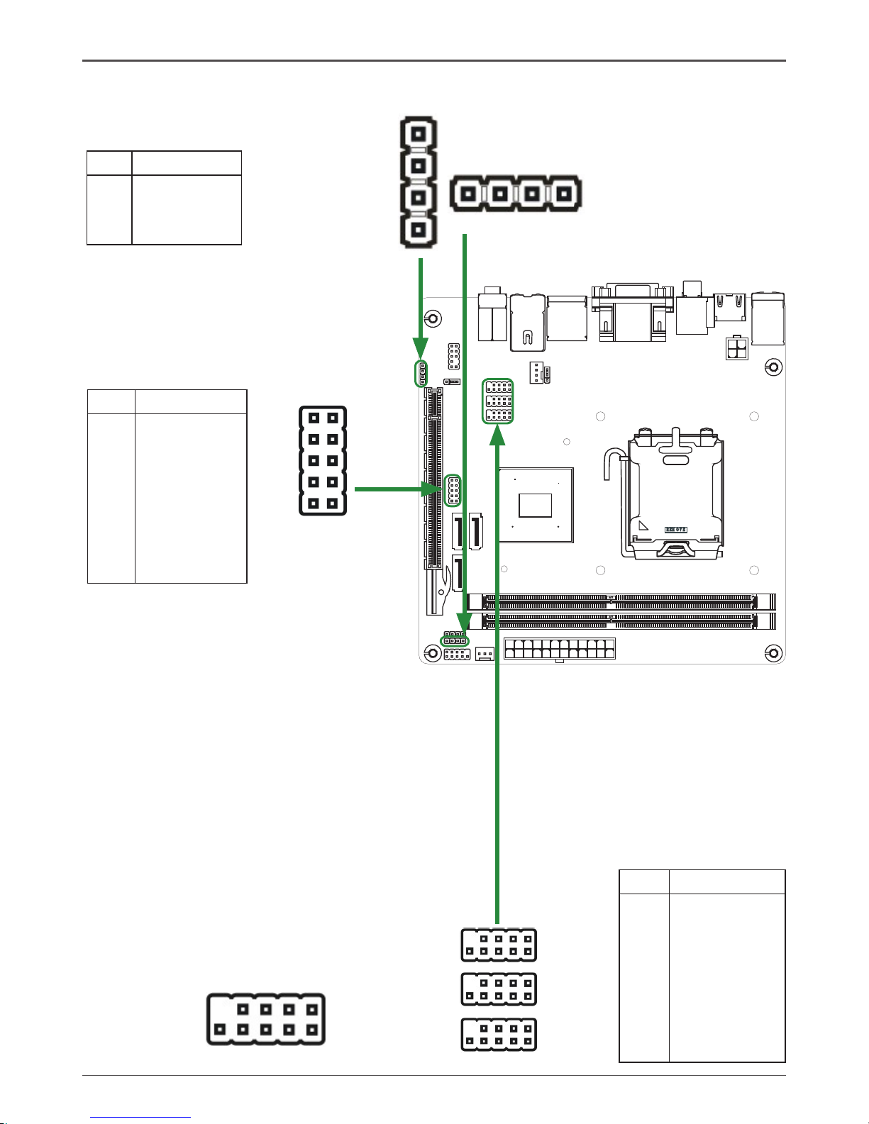
PIN Assignment
1 VCC
2 NC
3 NC
4 SPK-
SPK - Pin Definition
SPK Header
*
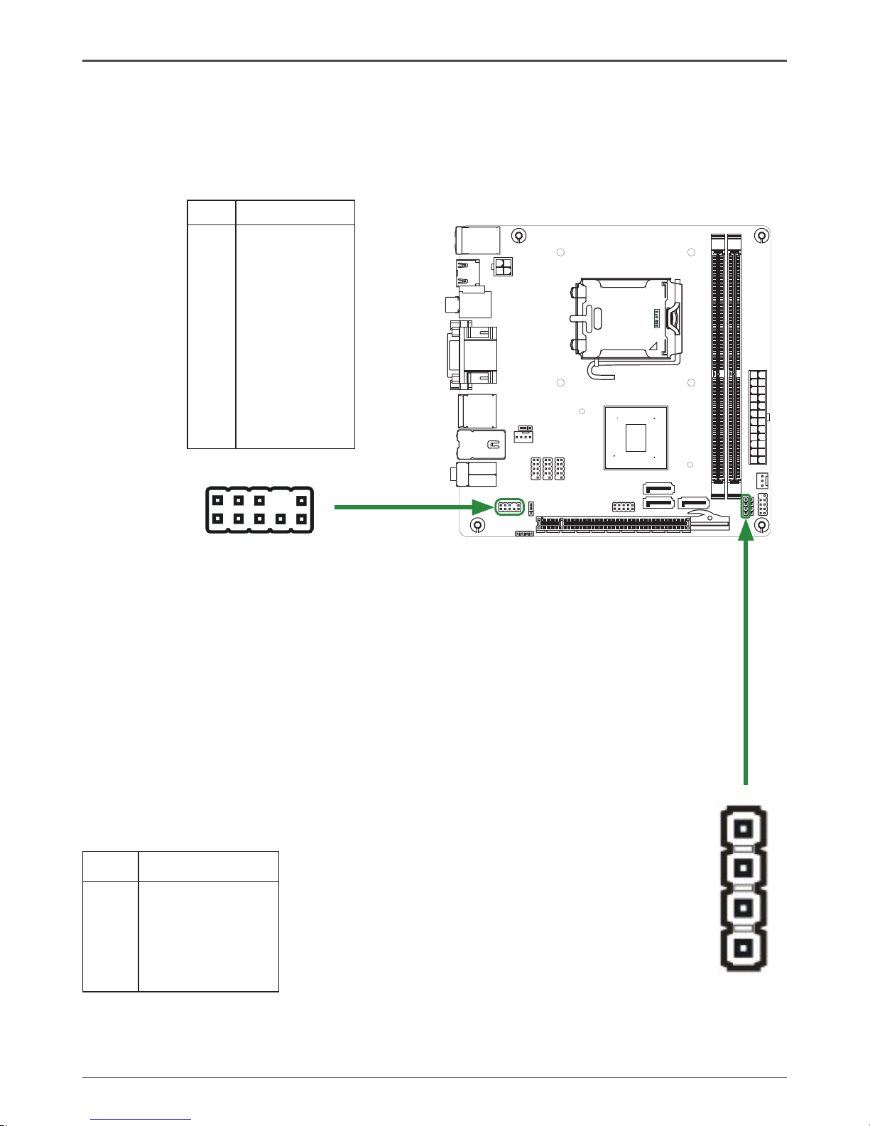
Serial Port Header - COM
COM
1
2
9
10
1
SPK
(PCB VER:00 only)
COM - Pin Definition
PIN Assignment
1 DCD
2 RXD
3 TXD
4 DTR
5 GND
6 DSR
7 RTS
8 CTS
9 RI
10 NC
USB Headers
This motherboard contains six USB 2.0
ports that are exposed on the rear panel
of the chassis(Figure 2). The motherboard
also contains six 10-pin internal header
connectors onboard.
1. Secure the bracket to either the front or
rear panel of your chassis (not all chassis
are equipped with the front panel option).
PIN Assignment
1 VCC
2 VCC
3 USBP0 4 USBP1 5 USBP0+
6 USBP1+
7 GND
8 GND
9 KEY
10 OC#
USB Pin Definition
19
10 2
FP_U2
FP_U1
FP_U3
1
SPK
(PCB Ver:01,03,04)
Page 16
15
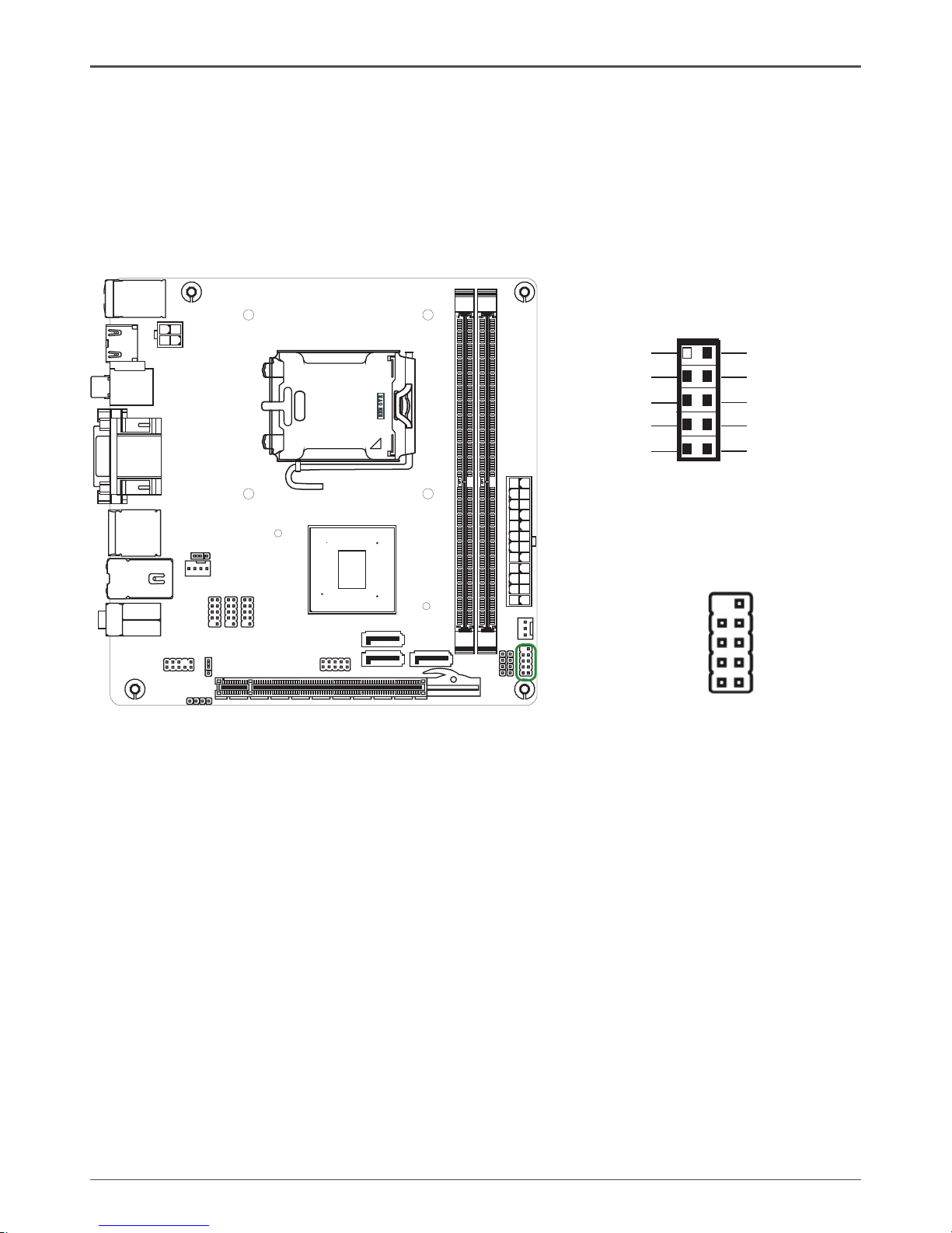
Front panel header
The front panel header on this motherboard is one connector used to connect the
following four cables.
q PWRLED
Attach the front panel power LED cable to these two pins of the connector. The
Power LED indicates the system’s status.
Note: Some chassis do not have all four cables. Be sure to match the name on
the connectors to the corresponding pins.
q PWR SW
Attach the power button cable from the case to these two pins. Pressing the
power button on the front panel turns the system on and off rather than using the
power supply button.
q HDD LED
Attach the hard disk drive indicator LED cable to these two pins. The HDD
indicator LED indicates the activity status of the hard disks.
q RST SW
Attach the Reset switch cable from the front panel of the case to these two pins.
The system restarts when the RESET switch is pressed.
120
240
121
120
240
121
LO
TES
RE O EVM
+
Hardware Installation
RESET
GND
HDD_LEDHDD_LED+
FP1
NC
PWR_SW
KEY
PW_LED+
7
9
5
3
1
6
8
10
2
4
GND
PW_LED-
Front Panel Header Pin Definition
Page 17
16
GeForce 9300/9400 ITX Series Motherboard
F_Audio Header
The audio connector supports HD audio standard and provides two kinds of audio
output choices: the Front Audio, the Rear Audio. The front Audio supports re-tasking
function.
Note:
In order to utilize the front audio header, your chassis must have front audio
connector. Also please make sure the pin assignment on the cable is the same
as the pin assignment on the mainboard header. To find out if the chassis you
are buying supports a front audio connector, please contract your dealer.
PIN Assignment
1 MIC2(L)
2 GND
3 MIC(R)
4 -ACZ-DET
5 Front Audio(R)
6 Reserved
7 FAVDIO - JD
8 Key (No pin)
9 Front Audio(L)
10 Reserved
F_Audio Pin Definition
120
240
121
120
240
121
LO
TES
RE O EVM
+
SPDIF-Out Header*
This header provides a SPDIF-Out (Sony/Philips Digital Interface) to digital
multimedia device through coaxial connector.
SPDIF - Pin Definition
PIN Assignment
1 SPDIF-out
2 VCC3
3 NC
4 GND
SPDIF
(PCB Ver:04 only)
1
2
1
10
9
FP_S1
Page 18
17
120
240
121
120
240
121
LO
TES
RE O EVM
+
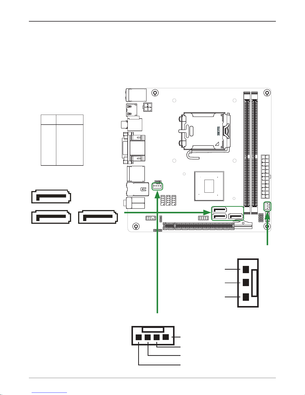
PIN SIGNAL
1 GND
2 TXP
3 TXN
4 GND
5 RXN
6 RXP
7 GND
SATA II Pin Definition
Connecting Serial ATA II Cables*
The Serial ATA II connector is used to connect the Serial ATA II device to the
motherboard. These connectors support the thin Serial ATA II cables for primary
storage devices. The current Serial ATA II interface allows up to 3Gb/s data transfer
rate.
There are two or three serial ATA II connectors on the motherboard that support AHCI
and RAID configurations.SATA II 3 support motherboard version:03,04.
Hardware Installation
SATA II-1
1
Fan Connections
There are two fan connections on the
motherboard. The fan speed can be
detected and viewed in the PC Health
Status section of the CMOS Setup.
SYS FAN Connector
Sense
+12V
GND
CPU FAN Connector
GND
+12V
Sense
Control
SATA II-2
1
SATA II-3
(PCB Ver:03,04)
1
Page 19
18
GeForce 9300/9400 ITX Series Motherboard
120
240
121
120
240
121
LO
TE S
RE O EVM
+
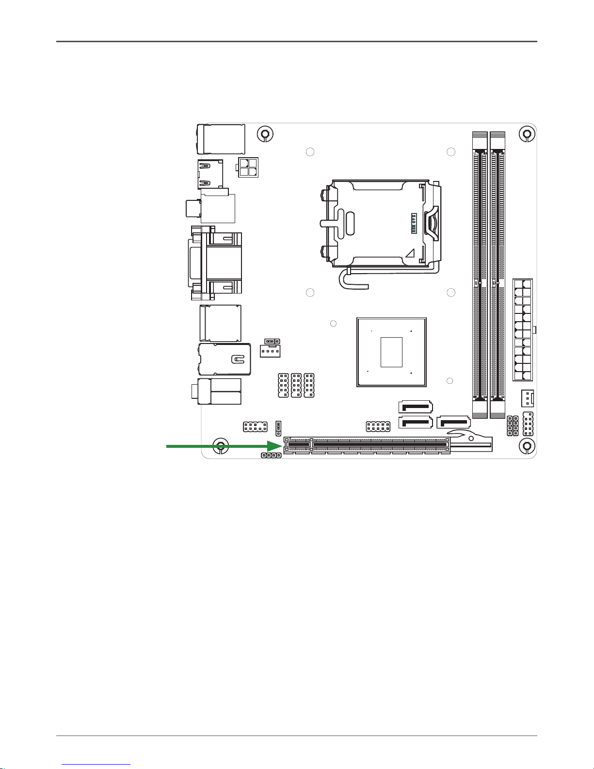
Expansion Slots
The NVIDIA MCP7a motherboard contains one expansion slot, PCI Express x16
graphics card supported by this motherboard.
PCI Express x16 Slots
There are one PCI Express x16 slot reserved for graphics or video cards. The bandwidth of the x16 slot is up to 8GB/sec complianting with PCIE 2.0 specification.
PCI Express x 16 slot
Page 20
19
Hardware Installation
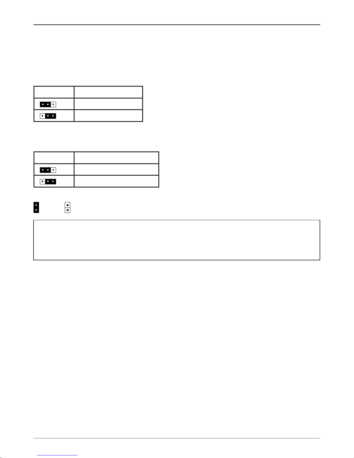
Jumper Settings*
This chapter explains how to configure the motherboard’s hardware. Before using your
computer, make sure all jumpers and DRAM modules are set correctly. Refer to this
chapter whenever in doubt.
Notice:
1. Be sure to save the CMOS setting when exit the CMOS.
2. If the CPU is frequency multiplier locked, no CPU speed change will be seen
even if the frequency multiplier setting in CMOS setup is changed.
Close Open * = Default setting.
If you want to clear the system conguration, use the JP1 (Clear CMOS Jumper) to clear data.
JP2 Selection
1-2* 5VSB*
2-3 5V
1
1
JP2-USB Power select(PCB VER:03,04)*
JP1-CMOS Clear Jumper
JP1 Selection
1-2* Normal*
2-3 CMOS Clear
1
1
If you want to USB wake up,Please select power to 5VSB,it is for PCB Ver:03,04.
Page 21

20
GeForce 9300/9400 ITX Series Motherboard
Conguring the BIOS
This section discusses how to change the system settings through the BIOS Setup
menus. Detailed descriptions of the BIOS parameters are also provided.
This section includes the following information:
q Enter BIOS Setup
q Main Menu
q Standard CMOS Features
q Advanced BIOS Features
q Advanced Chipset Features
q Integrated Peripherals
q Power Management Setup
q PnP/PCI Configurations
q Pc health status
q Frequency/Voltage Control
Enter BIOS Setup
The BIOS is the communication bridge between hardware and software. Correctly
setting the BIOS parameters is critical to maintain optimal system performance.
Use the following procedure to verify/change BIOS settings.
1. Power on the computer.,
2. Press the Del key when the following message briefly displays at the bottom of
the screen during the Power On Self Test (POST).
Press F1 to continue, DEL to enter Setup.
Pressing Del takes you to the Phoenix-Award BIOS CMOS Setup Utility.
Note: It is strongly recommended that you do not change the default BIOS
settings. Changing some settings could damage your computer.
If you do not find the setting you want in the Main Menu or a submenu, Press
<Ctrl>+<F1> to access more advanced options.
Page 22
21
Configuring the BIOS
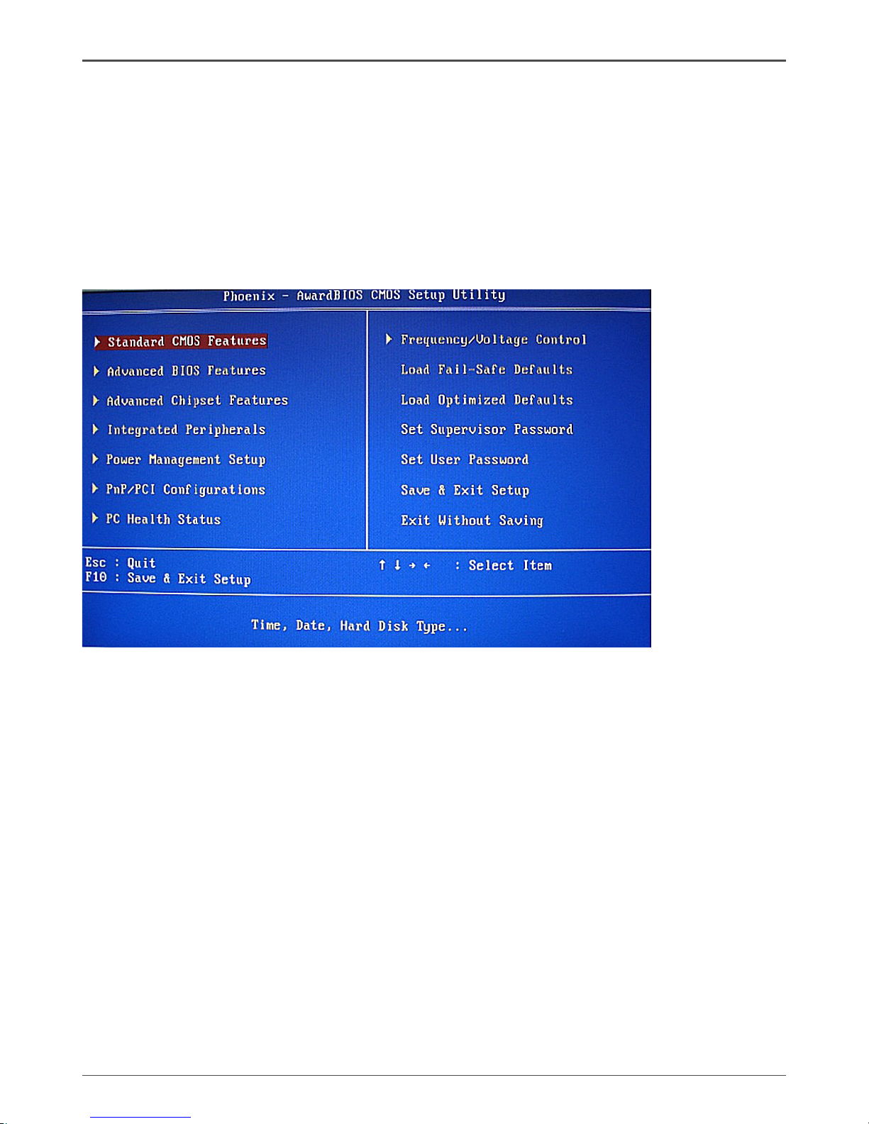
Main Menu
The main menu allows you to select from the list of setup functions and two exit
choices. Use the Page Up and Page Down keys to scroll through the options or press
Enter to display the associated submenu. Use the # $ arrow keys to position the
selector in the option you choose. To go back to the previous menu, press Esc.
Note: that on the BIOS screens all data in white is for information only,
data in yellow is changeable, data in blue is non-changeable, and
data in a red box is highlighted for selection.
q Standard CMOS Features
Use this menu to set up the basic system configuration.
q Advanced BIOS Features
Use this menu to set up the advanced system features and boot sequence.
q Advanced Chipset Features
Use this menu to optimize system performance.
q Integrated Peripherals
Use this menu to set up onboard peripherals such as IDE, RAID, USB and LAN
control.
q Power Management Setup
Use this menu to configure power management, power on, and sleep features.
q PnP/PCI Configurations
Use this menu to modify the system’s Plug-and-Play and PCI configurations.
q Pc health status
Use this menu to monitor the real-time system status of your PC.
Page 23
22
GeForce 9300/9400 ITX Series Motherboard
The following items on the CMOS Setup Utility main menu are commands rather than
submenus:
q Load Optimized Defaults
Load default system settings.
q Set Supervisor and User Password
Use this command to set, change, and disable the password used to access the
system and the BIOS menu.
q Save & Exit Setup
Use this command to save settings to CMOS and exit setup.
q Exit Without Saving
Use this command to abandon all setting changes and exit setup.
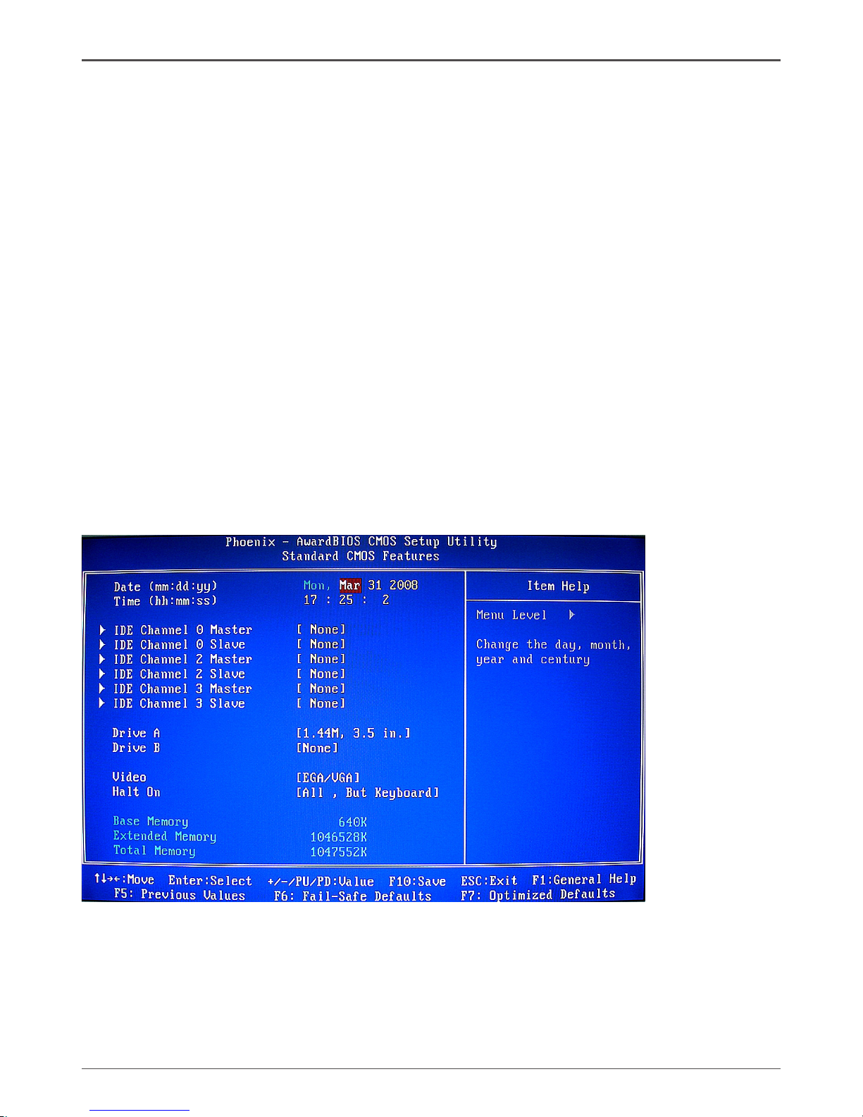
Standard CMOS Features Menu
The Standard CMOS Features menu is used to configure the standard CMOS
information, such as the date, time, HDD model, and so on. Use the Page Up and
Page Down keys to scroll through the options or press Enter to display the sub-menu.
Use the # $ arrow keys to position the selector in the option you choose. To go back
to the previous menu, press Esc.
The information shown in Item Help corresponds to the option highlighted.
Note: Note that all data in white is for information only, data in yellow is
changeable, data in blue is non-changeable, and data in a red box is
highlighted for selection.
Page 24

23
Configuring the BIOS
Date and Time
Using the arrow keys, position the cursor over the month, day, and year. Use the Page
Up and Page Down keys to scroll through dates and times. Note that the weekday
(Sun through Sat) cannot be changed. This field changes to correspond to the date you
enter. Note that the hour value is shown in a 24-hour clock format. Time is represented
as hour : minute : second.
IDE Channel
Use these functions to detect and configure the individual IDE channels. Select a
channel and press Enter to display the IDE sub-menu.
Press Enter to auto-detect IDE channels in the system. Once the channel is detected,
the values for Capacity, Cylinder, Head, Precomp, Landing Zone, and Sector are
automatically filled in.
q None
There is no HDD installed or set.
q Auto
The system can auto-detect the hard disk when booting up.
q Manual
When you set the channel to [Manual] and change Access Mode to [CHS],
you can then enter the number of cylinders, heads, Precomp, landing zone, and
sector.
Video
Use this option to choose the mode of Video, as EGA/VGA, CGA 40, CGA 80,
MONO.
Drive A
The Drive A option allows you to select the kind of FDD to install.
Halt On
Halt On determines whether or not the computer stops if an error is detected during
power on. Use the Page Up and Page Down keys to scroll through the options or
press Enter to display the Halt On sub-menu. Use the # $ arrow keys to position
the selector in the option you choose. Press Enter to accept the changes and return
to the Standard CMOS Features menu.
q All Errors
Whenever the BIOS detects a nonfatal error, the system stops and prompts you.
q No Errors
System boot does not stop for any detected errors.
q All, But Keyboard
System boot does not stop for keyboard errors, but does stop for all other errors.
q All, But Diskette
The system boot does not stop for a diskette error but will stop for all other errors.
Page 25

24
GeForce 9300/9400 ITX Series Motherboard
q All, But Disk/Key
These field are read-only and are determined by the BIOS POST.
Memory
These settings are display-only values that are determined by the BIOS POST
(Power-On Self Test).
q Base Memory
BIOS POST determines the amount of base (or conventional) memory installed
in the system.
q Extended Memory
BIOS determines how much extended memory is present during the POST.
q Total Memory
This value represents the total memory of the system.
Advanced BIOS Features
Access the Advanced BIOS Features menu from the CMOS Utility Setup screen. Use
the Page Up and Page Down keys to scroll through the options or press Enter to
display the sub-menu. Use the # $ arrow keys to position the selector in the option
you choose. To go back to the previous menu, press Esc.
Note: The options that have associated sub-menus are designated by a u,
which precedes the option. Press Enter to display the sub-menus.
Page 26

25
Configuring the BIOS
Note: Note that all data in white is for information only, data in yellow is
changeable, data in blue is non-changeable, and data in a red box is
highlighted for selection.
CPU Feature
Press Enter to display the CPU Feature menu.
Page 27

26
GeForce 9300/9400 ITX Series Motherboard
q PPM Mode
Use this option to choose the mode of PPM.
q Limit CPUID MaxVal
Use this option to enable or disable the function of Limiting CPUID MaxVal
q C1E Function
Select CPU C1E function.
q Execute Disable Bit
When disabled forces the XD feature flag to always return 0, defaults choose
Enable.
q Virtualization Technology
Use this option to enable or disable Virtualization Technology.
q Core Multi-Processing
Use this option to enable or disable Core Multi-Processing.
Hard Disk Boot Priority
Press Enter to disply the Hard Disk Boot Priority.
q Bootable Add-in Cards
Use this option to bootable add-in cards.
q Virus Warning
Allow you to choose the Virus Warning feature for IDE Hard Disk boot sector
protection.
q CPU L1&L2 Cache/CPU L3 Cache
Use these options to disable or enable L1/L2/L3 cache.
Page 28

27
Configuring the BIOS
q Quick Power On Self Test
Enabling this option allows the system to skip certain test while booting, which
reduces the time needed to boot the system.
q First/Second/Third Boot Device
Use this option to set the priority sequence of the devices booted at power on.
Use the Page Up and Page Down keys to scroll through the options or press
Enter to display the sub-menu. Use the # $ arrow keys to position the
selector in the option you choose.
q Boot Other Device
With the option set to Enable, the system boots from some other device if the
first/second/third boot devices fail.
q Boot Up Floppy Seek
Enabled tests floppy drives to determine whether they have 40 or 80 tracks.
q Boot Up NumLock Status
This option allows you to select the power-on state of NumLock. Select On
to activate the keyboard NumLock when the system is started. Select Off to
disable the NumLock key.
q Gate A20 Option
Use this option to choose Gate A20 menu.
q Typematic Rate Setting
Use this option to set keystrokes repeat. if Enabled, display options as follows:
v Typematic Rate
v Typematic delay
q Security Option
The Security Options allows you to require a password every time the system
boots or only when you enter setup. Select Setup to require a password to gain
access to the CMOS Setup screen. Select System to require a password to
access the CMOS Setup screen and when the system boots.
q APIC Mode
Use this function to enable or disable the Advanced Programmable Interrupt
Controller (APIC). If you disable this option, you also disable the MPS Version
Control for OS option.
q MPS Version Control For OS
Use this function to select the Multi-Processor Specification (MPS) version that
BIOS passes to the operating system. Use the Page Up and Page Down
keys to scroll through the options.
q Full Screen LOGO Show
This option allows you to enable or disable the display of the full-screen logo
when the system boots. Use the Page Up and Page Down keys to toggle
between Enable and Disable.
q Small LoGo (EPA) Show
This option allows you to enable or disable the display of the Small LoGo when
the system boots.
Page 29

28
GeForce 9300/9400 ITX Series Motherboard
Advanced Chipset Features
Select Advanced Chipset Features from the CMOS Setup Utiltiy menu and press
Enter to display the functions of the Advanced Chipset Functions menu.
q Spread Spectrum Control
Use this option to set Spread Spectrum
q Onboard GPU
Use this option to set Onboard GPU
q Frame Buffer Size
Use this option to change Buffer Size
q System BIOS Cacheable
Use this option to enable or disable the System BIOS Cacheable
Page 30

29
Configuring the BIOS
Integrated Peripherals Menu
Select Integrated Peripherals from the CMOS Setup Utility menu and press
Enter to display the Integrated Peripherals menu.
q IDE Function Setup
Use this option to set IDE function
q MCP Storage Config
Use this option to set MCP Storage
q MCP Hardware Momitor
Use this option to set MCP Hardware
q MCP Super io Config
Use this option to set MCP Super io
q HD Audio
Use this option to set HD Audio
q MAC Lan
Use this option to set MAC Lan
q MAC Media Interface
Use this option to set MAC Media
q Machine MAC(NV) Address
When set this option to “Enable“, you can set a new address for current
MAC(NV)
q USB Device Setting
Use this option to set USB device.
Page 31

30
GeForce 9300/9400 ITX Series Motherboard
Power Management Setup Menu
Select Power Management Setup from the CMOS Setup Utility menu and press
Enter to display the Power Management Setup menu.
q ACPI Function
This function on the Power Management Setup menu allows you to enable or
disable the ACPI function.
q Power Management
Use this option to set the mode for Power Management
q Video Off Method
Use this option to set a Method for Video off.
q HDD Power Down
Use this option to enable or disable a mode of HDD Power down.
q Soft-Off by PBNT
This function on the Power Management Setup menu allows you to set Soft-Off
by PBNT to [Instant-Off] or [Delay 4 Sec].
q PowerOn after PWR-fail
Use this option to change its setting
q Power-On by Alarm
Determines whether to power on the system at a desired time. If enable set the
date and time as following:
v Date(of Month) Alarm: Turn on the system at a specific time on each day or
on a specific day in a month.
v Time(hh:mm:ss) Alarm: Set the time at which the system will be Powered
on automatically.
Page 32

31
Configuring the BIOS
q PowerOn Function
Use this option to Power On Mode(by button only, keyboard 98, mouse left/right,
hot key, password or any key. )
q HPET Support
Use this option to enable or disable HPET Support; if enable, HPET Mode
display. We can select.
PnP/PCI Congurations
Select PnP/PCI Conguration from the CMOS Setup Utility menu and press
Enter to display the PnP/PCI Configuration menu.
q Init Display First
This function on the PnP/PCI Configuration menu allows you to define if the initial
display is in the PCI slot, onboard or PCI Express slot. Options are [PCI Slot],
[Onboard] and [PCIEx].
q Reset Configuration Data
This function on the PnP/PCI Configuration menu allows you to enable or
disable the resetting of Extended System Configuration Data (ESCD) when
you exit Setup. Set this to [Enabled] if you have installed a new add-on and
the system reconfiguration has caused a serious conflict that prevents the OS
from booting. The default setting is [Disabled].
Page 33

32
GeForce 9300/9400 ITX Series Motherboard
q Resources Controlled By
This function on the PnP/PCI Configuration menu allows you to define if the
BIOS can automatically configure all the boot and plug-and-play compatible
devices or if you can manually select IRQ, DMA, and memory base address
fields. Select [Auto(ESCD)] if you want the BIOS to automatically populate
these fields. If you select [Manual] so you can assign the resources, IRQ
Resources is enabled for input.
q IRQ Resources
To enable this field for input, set Resources Controlled By to [Manual].
With this field enabled, press Enter to see options.
Use Legacy ISA for devices compliant with the original PC AT Bus specification.
Use PCI/ISA PnP for devices compliant with the plug-and-play standard, whether
designed for PCI or ISA Bus architecture.
q PCI/VGA Palette Snoop
This function on the PnP/PCI Configuration menu allows you to enable or disable
the Palette Snoop function.
q Maximum Payload Size
This function on the PnP/PCI Configuration menu allows you to set the maximum
TLP payload size (in bytes) for the PCI Express devices. Use the Page Up
and Page Down keys to scroll through sizes or enter the number using
the keyboard numbers or use the + and – keys to go up and down the list of
sizes.
Page 34

33
Frequency/Voltage Control
Select Frequency/Voltage Control from the CMOS Setup Utility menu and press Enter
to display the system Monitor menu.
q System Clock
Press “Enter“ to display System Clock status
q FSB&Memory config
Use this option to change FSB&Memory setting
q MEM Voltage control
Use this option to set Merry Voltage
q NB Voltage control
Use this option to set NB Voltage
q CPU Voltage adjust
Use this option to set CPU Voltage
Configuring the BIOS
Page 35

34
GeForce 9300/9400 ITX Series Motherboard
Page 36

35
Load Optimized Defaults
Press <Enter> on this item and then press the <Y> key to load the optimal BIOS
default settings. The BIOS defaults settings helps the system to operate in optimum
state. Always load the Optimized defaults after updating the BIOS or after clearing the
CMOS values.
Configuring the BIOS
Page 37

36
GeForce 9300/9400 ITX Series Motherboard
Set Supervisor/User Password
Press <Enter> on this item and type the password with up to 8 characters and then
press <Enter>. You will be requested to confirm the password. Type the password
again and press <Enter>.
The BIOS Setup program allows you to specify two separate passwords:
v Supervisor Password
When a system password is set and the Password Check item in Advanced
BIOS Features is set to Setup, you must enter the supervisor password for enter-
ing BIOS Setup and making BIOS changes.
When the Password Check item is set to System, you must enter the supervisor
password (or user password) at system startup and when entering BIOS Setup.
v User Password
When the Password Check item is set to System, you must enter the supervisor
password (or user password) at system startup to continue system boot. In BIOS
Setup, you must enter the supervisor password if you wish to make changes to
BIOS settings. The user password only allows you to view the BIOS settings but
not to make changes.
To clear the password, press <Enter> on the password item and when requested
for the password, press <Enter> again. The message “PASSWORD DISABLED” will
appear, indicating the password has been cancelled.
Page 38

37
Configuring the BIOS
Save & Exit Setup
Press <Enter> on this item and press the <Y> key. This saves the changes to the
CMOS and exits the BIOS Setup program. Press <N> or <Esc> to return to the BIOS
Setup Main Menu.
Exit Without Saving
Press <Enter> on this item and press the <Y> key. This exits the BIOS Setup without
saving the changes made in BIOS Setup to the CMOS. Press <N> or <Esc> to return
to the BIOS Setup Main Menu.
Page 39

38
GeForce 9300/9400 ITX Series Motherboard
FLASH Update Procedure
The program AWDFLASH.EXE is included on the driver CD (D:\Utility\
AWDFLASH.EXE). Please follow the recommended procedure to update the flash
BIOS, as listed below.
1. Create a DOS-bootable floppy diskette. Copy the new BIOS file (just obtained or
downloaded) and the utility program AWDFLASH.EXE to the diskette.
2. Allow the PC system to boot from the DOS diskette.
3. At the DOS prompt, type
AWDFLASH<ENTER>
4. Enter the file name of the new BIOS.
5. The question: “Do you want to save BIOS (Y/N)?” is displayed.
Press “N” if there is no need to save the existing BIOS.
Press “Y” if a backup copy of the existing BIOS is needed.
(A file name has to be assigned to the existing BIOS binary
file.)
6. The message : “Press “Y” to program or “N” to exit” is displayed. Type
“Y”<ENTER>
7. Wait until the flash-update is completed.
8. Restart the PC.
Warning : - Do not turn off or RESET the computer during the flash
process.
- If you are not sure how to upgrade the BIOS, please take your com
puter to an Authorized Service Center and have a trained technician
do the work for you.
Page 40

39
Installing Drivers and Software
Note: It is important to remember that before installing the driver CD that is
shipped in the kit, you need to load your operating system. The
motherboard supports Windows XP 32bit and 64bit and is Vista-capable.
The kit comes with a CD that contains utility drivers and additional software.
The CD that has been shipped with your NVIDIA MCP7A motherboard contains the
following software and drivers:
q Nvidia chipset driver
q HDA Sound driver
Installing Drivers and Software
Page 41

40
GeForce 9300/9400 ITX Series Motherboard
Drivers Installation
1. Insert the driver CD after loading your operating system. Waiting for one
menute you can see below interface.
2. Follow the below steps to install Nvidia shipset driver.
Page 42

41
Installing Drivers and Software
Page 43

42
GeForce 9300/9400 ITX Series Motherboard
3. Follow the below for HDA sound driver installing.
Page 44

43
Installing Drivers and Software
At last, you can open below page that provides information about the hardware devices on this motherboard, and check whether finish your installation.
Page 45

44
GeForce 9300/9400 ITX Series Motherboard
HDMI SETUP
1. You can connect HDMI device to the HDMI port directly, or connect to DVI
port by a DVI - HDMI dongle.
2. Enter Control Panel, double click “Sounds and Auddio Devices”, select
“NVIDIA HDMI Audio” as default play back device, then click ok.
Page 46

45
Installing Drivers and Software
Realtek HD Audio Driver Setup
Getting Started
After Realtek HD Audio Driver being installed (insert the driverCD and follow the onscreen instructions), “Realtek HD Audio Manager” icon will show in System tray as
below. Double click the icon and the control panel will appear:
Sound Effect
After clicking on the “Sound Effect” tab, 3 sections “Environment”, “Equalizer” and
“Karaoke” are available for selection.
Environment Simulation
You will be able to enjoy different sound experience by pulling down the arrow, totally
23 kinds of sound effect will be shown for selection. Realtek HD Audio Sound Manager
also provides five popular settings “Stone Corridor”, “Bathroom”, “Sewer pipe”, “Arena”
and “Audio Corridor” for quick enjoyment.
Page 47

46
GeForce 9300/9400 ITX Series Motherboard
Equalizer Selection
The Equalizer section allows you to create your own preferred settings by utilizing
this tool.
In standard 10 bands of equalizer, ranging from 100Hz to 16KHz are available:
Frequently Used Equalizer Setting
Realtek recognizes the needs that you might have. By leveraging our long experience
at audio field, Realtek HD Audio Sound Manager provides you certain optimized equalizer settings that are frequently used for your quick enjoyment.
How to Use
Other than the buttons “Pop” “Live” “Club” & “Rock” shown on the page, to pull down
the arrow in “Others” , you will find more optimized settings available to you.
Karaoke Mode
Karaoke mode brings Karaoke fun back home by simply using the music you usually
play, Karaoke mode can help you eliminate the vocal of the song or adjust the key to
accommodate your range.
Vocal Cancellation: Single click on “Voice Cancellation”, the vocals of the songs will
be erased, while the background music is still playing which lets you take over the vocal
part.
Key Adjustment: Using “Up / Down Arrow” to find a key which better fits your vocal
range.
Page 48

47
Installing Drivers and Software
Mixer
Realtek HD Audio Sound Manager integrates Microsoft’s “Volume Control” functions
into the Mixer page. This gives you the advantage to you to create your favorite sound
effect in one single tool.
Playback control
Mute
You may choose to mute single or multiple volume controls or to completely mute
sound output.
Tool
√ Show the following volume control
This is to let you freely decide which volume control items to be displayed, total
13 items to be chosen.
√ Advanced controls
√ Enable playback multi-streaming
Page 49

48
GeForce 9300/9400 ITX Series Motherboard
With this function, you will be able to have an audio chat with your friends via headphone
(stream 1 from front panel) while still have music (stream 2 from back panel) playing.
At any given period, you can have maximum 2 streams operating simultaneously.
Recording control
Mute
You may choose to mute single or multiple volume controls or to completely mute
sound input.
Tool
√
Show the following volume controls
This is to let you freely decide which volume control items to be displayed.
√ Advanced controls.
Advanced control is a “Microphone Boost” icon.
Once this item is checked, you will find “advanced” icon beside “Front Pink In” &
“Mic Volume”. With this, the input signal into “Front Pink In” & “Mic Volume” will
be strengthen.
√ Enable recording multi-streaming
At any given period, you can have maximum 2 streams operating simultaneously.
Page 50

49
Installing Drivers and Software
Audio I/O
Realtek HD Audio Manager frees you from default speaker settings. Different from
before, for each jack, they are not limited to perform certain functions. Instead, now
each jack is able to be chosen to perform either output (i.e. playback) function or input
(i.e. Recording) function, we call this “Retasking”.
Audio I/O aims to help you setting jacks as you wish. Moreover, other than blue to blue,
pink to pink, the way that you used to do, Audio I/O would guide you to other right jacks
that can also serve as microphone / speaker / headphone.
Page 51

50
GeForce 9300/9400 ITX Series Motherboard
Speaker Configuration
Step 1: Plug in the device in any available jack.
Step 2: Dialogue “connected device” will pop up for your selection. Please select the
device you are trying to plug in.
* If the device is being plugged into the correct jack, you will be able to find the icon
beside the jack changed to the one that is same as your device.
* If not correct, Realtek HD Audio Manager will guide you to plug the device into the
correct jack.
Page 52

51
Installing Drivers and Software
Connector Settings
Click to access connector settings
√ Mute rear panel when front headphone plugged in
Once this option is checked, whenever front headphone is plugged, the music
that is playing from the back panel, will be stopped.
√ Disable front panel jack detection (option)
Did not find any function on front panel jacks?
Please check if front jacks on your system are so-called AC’97 jacks. If so,
please check this item to disable front panel jack detection.
√ Enable auto popup dialogue, when device has been plugged in.
Once this item checked, the dialog “Connected device”, would not automatically
pop up when device plugged in.
S/PDIF
Short for Sony/Philips Digital Interface, a standard audio file transfer format. S/PDIF
allows the transfer of digital audio signals from one device to another without having
to be converted first to an analog format. Maintaining the viability of a digital signal
prevents the quality of the signal from degrading when it is converted to analog.
Page 53

52
GeForce 9300/9400 ITX Series Motherboard
√
Output Sampling Rate
- 44.1KHz: This is recommended while playing CD
- 48KHz: This is recommended while playing DVD or Dolby.
- 96KHz: This is recommended while playing DVD-Audio.
√
Output Source
- Output digital audio source: The digital audio format (such as .wav, .mp3,
.midi etc) will come out through S/PDIF-Out.
Speaker Calibration
After you have successfully plugged in speakers and assigned to the right jacks, you are
only one more step to go to enjoy the intended sound. We provide “Speaker Calibration”
to help you check if the speakers are located in the correct position.
Page 54

53
Installing Drivers and Software
Microphone
This page is designed to provide you better microphone / recording quality.
Below picture indicates both “Noise Suppression” & “Acoustic Echo
Cancellation” are both enabled.
Noise Suppression
If you feel that the background noise, especially the sound generated from the fan
inside PC, is too loud? Try “Noise Suppression”, which allows you to cut off and suppress disturbing noise.
Beam Forming
Also known as “directional recording”, this option lets you do the following: Once beam
forming is enabled; only the sound from certain direction will be recorded. You will get
the best quality if you chose 90° position, which we recommend you to use, this effectively means that you speak right into the microphone.
Note: A Stereo Microphone is required when using Beam Forming function.
Acoustic Echo Cancellation
This function prevents playback sound from being recorded by microphone together
with your sound. For example, you might have chance to use VOIP function through
Internet with your friends. The voice of your friend will come out from speakers (playback). However, the voice of your friend might also be recorded into your microphone
then go back to your friend through Internet. In that case, your friend will hear his/her
own voice again. With AEC (Acoustic Echo Cancellation) enabled at your side, your
friend can enjoy the benefit with less echo.
Page 55

54
GeForce 9300/9400 ITX Series Motherboard
Audio Demo
The section “3D Audio Demo” grants you another possibility to enjoy your sound. The
Audio Demo allows you to listen to sound in an extraordinary way.
Information
This section provides information about your current system audio device.
Page 56

55
Installing Drivers and Software
SATA RAID User Manual
Setting up the BIOS
1. Setting your computer, then press Delete to enter the Bios setup. The BIOS
CMOS Setup Utility window appears.
2. Use the arrow keys to select Integrated Peripherals, then press Enter.
TheIntegrated Peripherals window appears.
Page 57

56
GeForce 9300/9400 ITX Series Motherboard
4. From the RAID Config window,enable RAID, then enable the disks that you want
to use as RAID disks.
5. Press F10 to save the configuration and exit. The PC reboots.
6. Enter the RAID BIOS Setup by pressing F10 when prompted, and proceed to set
up the NVRAID BIOS as described in the next Section.
3. Use the arrow keys to select the RAID Config, then press Enter. The RAID
Config window appears.
Page 58

57
Installing Drivers and Software
Entering the RAID BIOS Setup
1. After rebooting your computer, wait until you see the RAID software promptint
you to press F10.
2. The NVIDIA RAID Utility –Define a New Array window appears
3. In the RAID Mode field, use the UP or Down ARROW key to select a RAID Mode.
The supported RAID modes include Mirroring (RAID 1), Striping (RAID 0) and
Stripe Mirroring (RAID 0+1), Spanning(JBOD) and RAID 5. The following is an
example of RAID 0 array creation.
4. If RAID 0(Striping) is selected, you can manually set the striping block size. in the
Striping Block field, use the UP or DOWN ARROW ey to set the Striping Block
size. The KB is standard unit of Striping Block size. We recommend you leaving
it to the default setting-Optimal(64k). The size range is from 4k to 128k.
5. Select the hard drivers which you wish to be included in the disk array. The Free
Disks section displays the information about the currently installed SATA hard
drives. Press the TAB key to move to the Free Disks section. Select the target
hard drives using the UP or DOWN ARROW key and use the RIGHT ARROW key
to add the hard drives to the Array Disks section.
Page 59

58
GeForce 9300/9400 ITX Series Motherboard
6. Press F7 after selecting the target hard disks. A message which says “Clear disk
data?” will appear. If you are sure to clear the data in the selected hard drives,
press Y. (If the hard drives contain previously created RAID array, you need to
press Y to clear the data from the hard drives.)
7. After that, then Array List screen displaying the RAID array you created will appear.
If you want to set the disk array as boot device, use the UP or DOWN ARROW
key to select the array and press B. The Boot section will show Yes.
Page 60

59
Installing Drivers and Software
8. To read more information about the RAID array, press ENTER to enter the Array
Detail screen, where you should see detailed information about RAID mode, disk
block size, disk model name, and disk capacity, etc.
9. To delete the array, press D in the Array Detail screen. When the “Delete
this array?” message appears, press Y to confirm or N to cancel. Press
ENTER to return to the Array List screen. To exit the Nvidia RAID utility,
press ESC in the main menu or Ctrl+X in the Array List screen. Now, you
can proceed to install the SATA controller driver and operating system.
Page 61

60
GeForce 9300/9400 ITX Series Motherboard
Installing the RAID Drivers
1. After you complete the RAID BIOS setup, boot from the windowsXP CD. The
Windows Setup program starts.
2. Press F6 and wait a few moments for the Windows Setup screen to appear.
Page 62

61
Installing Drivers and Software
3. Specify the NVIDIA drivers.
(1). Insert the floppy that has the RAID driver, press S, then press Enter.
(2). Select “NVIDIA RAID CLASS DRIVER” and then press Enter.
Page 63

62
GeForce 9300/9400 ITX Series Motherboard
(3). Press S again at the Specify Devices screen, then press Enter.
(4). Select “NVDIA Nforce Storage Controller” and then press Enter.
4. Press Enter to continue with Windows XP Installation.
Be sure to leave the floppy disk inserted in the floppy drive until the blue screen
portion of Windows XP installation is completed, then take out the floppy.
5. Follow the instructions on how to install Windows XP.
During the GUI portion of the install you might be prompted to click Yes to install
the RAID driver. Click Yes as many times as needed in order to finish the installation. This will not be an issue with a signed driver.
Page 64

63
Reference Information
Hybrid SLI Technology
Built upon NVIDIA SLI® technology, Hybrid SLI® enables NVIDIA® discrete GPUs
and NVIDIA motherboard GPUs to work together to deliver multi-GPU benefits. Hybrid
SLI provides significant performance scaling through GeForce® Boost and compelling
power and noise reduction benefits through HybridPower™.
Hybrid SLI
SLI technology enables two discrete GPUs to work together and provide increased
graphics performance. Hybrid SLI technology is similar to SLI technology in that it
enables a motherboard GPU (mGPU) to work with a discrete GPU (dGPU) to provide
two key benefits to the user.
q GeForce Boost
The GeForce Boost feature enables the motherboard GPU to work collaboratively
with the discrete GPU to increase the performance of the discrete GPU. When
GeForce Boost is enabled, the mGPU and dGPU share the rendering load by
rendering different frames of an image. Thus the graphics processing power of the
mGPU is harnessed to enhance the processing power of the dGPU.
q HybridPower
The HybridPower feature enables the user to switch off the dGPU when the maximum performance of the dGPU is not required and use the mGPU for non-intensive graphics applications, such as high definition DVD playback, Web surfing,
and office productivity applications. Switching off the dGPU not only lowers the
total system power consumption but also lowers total system noise and heat.
Hybrid SLI Technology
Page 65

64
GeForce 9300/9400 ITX Series Motherboard
Hybrid SLI Requirements
q Hybrid SLI-enabled motherboard and discrete GPUs (go to www.nvidia.com/
hybridSLI for a full list.)
q HybridPower-enabled power supply (go to www.nvidia.com/hybridSLI for a full
list.)
q Windows Vista operating system
q At least 2GB of system memory
q Latest NVIDIA Graphics Driver from www.nvidia.com
q Systems BIOS programmed to enable Hybrid SLI (see next page)
Supported dGPUs
GeForce Boost
The GeForce Boost feature of Hybrid SLI works only with specific dGPUs whose performance is comparable with the mGPU. The list of dGPUs supported by the GeForce
Boost feature can be found at www.nvidia.com/hybridsli.
Note:
For best GeForce Boost performance, an AMD Phenom CPU that supports HT3 protocol is recommended.
HybridPower
The HybridPower feature is supported by specific dGPUs that are able to power down
or enter into a low power state when the system enters Save Power mode, or stay
on in Boost Performance mode. The list of the dGPUs supported by the HybridPower
feature can be found at www.nvidia.com/hybridsli.
Multi-GPU SLI Support in Hybrid SLI Systems
Certain Hybrid SLI-enabled motherboards also support multi-GPU SLI set ups. In this
case, SLI works as it normally does—with two or more GPUs connected to power one
display. Connecting the display to the mGPU enables HybridPower and allows the
user to enter Save Power mode. Note that when more than one dGPU is plugged into
a Hybrid SLI system, the GeForce Boost feature is not available.
Page 66

65
Enabling Hybrid SLI
Enabling HybridPower
To enable HybridPower, the switches that control Hybrid SLI must be set to the
appropriate values in the System BIOS settings. Go into the system BIOS and go
to AdvancedChipset to ensure that the following settings are set to the values
given:
q Hybrid Support: ..........................Enabled
This enables hybrid functionality in the BIOS.
q Onboard or mGPU Enable:...........Enabled
When Hybrid is enabled, the Onboard GPU is automatically enabled.
q Preferred or Primary Boot GPU:..mGPU
This sets the primary display adapter. For HybridPower, this must be set to
mGPU.
q mGPU Frame Buffer Control:.......Manual
q mGPU Frame Buffer Size:............256 MB
The Frame Buffer size must be set to a minimum of 256MB for Hybrid SLI.
Note:
There may be differences in these menu items depending upon the manufacturer of
your motherboard.
Hybrid SLI Technology
Page 67

66
GeForce 9300/9400 ITX Series Motherboard
Enabling GeForce Boost
To enable GeForce Boost, the switches that control Hybrid SLI must be set to the
appropriate values in the System BIOS settings. Go into the system BIOS and go
to AdvancedChipset to ensure that the following settings are set to the values
given:
q Hybrid Enable: ............................Enabled
This enables hybrid functionality in the BIOS.
q Onboard or mGPU Enable: .......... Enabled
When Hybrid is enabled, the Onboard GPU is automatically enabled.
q Preferred or Primary Boot GPU:..mGPU
This sets the primary display adapter. For GeForce Boost, this can be set to
either the mGPU or the dGPU.
q mGPU Frame Buffer Control: ......Manual
q mGPU Frame Buffer Size: ...........256 MB
The Frame Buffer size must be set to a minimum of 256MB for Hybrid SLI.
Note:
There may be differences in these menu items depending upon the manufacturer of
your motherboard.
When the System BIOS is setup correctly and the Hybrid SLI drivers are installed on a hybridenabled system, the Hybrid UI icon displays in the Windows Vista system tray.
Click the icon to display the Hybrid UI
Page 68

67
Disabling Hybrid SLI
Traditional dGPU Mode
The Hybrid SLI feature can be disabled if desired by settings the appropriate Hybrid
SLI switches in the System BIOS settings. The system can be put into the traditional
operating mode where the discrete GPU performs all the graphics processing and
drives the display. The motherboard GPU will be disabled in this mode. To disable
Hybrid SLI and put the system in the traditional dGPU based operating mode, the following switches in the System BIOS settings must be set to the corresponding values
given below. Go into the system BIOS and go to AdvancedChipset to ensure that
the following settings are set to the values given:
q Hybrid Enable: ............................Disabled
This disables hybrid functionality in the BIOS.
q Onboard or mGPU Enable:...........Disabled
When Hybrid is disabled, the Onboard GPU is automatically disabled.
q Preferred or Primary Boot GPU:..dGPU
This sets the primary display adapter. This is automatically set to dGPU when
Hybrid is disabled.
q mGPU Frame Buffer Control:.......Manual
q mGPU Frame Buffer Size:............0 MB
The Frame Buffer size must be set to the lowest possible value when the Onboard/
mGPU is disabled.
Note:
There may be differences in these menu items depending upon the manufacturer of
your motherboard.
Hybrid SLI Technology
Page 69

68
GeForce 9300/9400 ITX Series Motherboard
Multi-adapter Mode
When Hybrid SLI is disabled, the system can be programmed to be in multi-adapter
mode by enabling both the dGPU and mGPU. This will allow the user to connect
displays to both the mGPU and the dGPU. The system can be put into multi-adapter
mode by setting the appropriate Hybrid SLI switches in the System BIOS settings. Go
into the system BIOS and go to AdvancedChipset to ensure that the following settings are set to the values given:
q Hybrid Enable:..............................Disabled
This disables hybrid functionality in the BIOS.
q Onboard or mGPU Enable: ..........Enabled
When Hybrid is disabled, the Onboard GPU is automatically disabled. The user
must manually enable the mGPU to enable multi adapter mode.
q Preferred or Primary Boot GPU:..dGPU
This sets the primary display adapter. This is automatically set to dGPU when
Hybrid is disabled.
q mGPU Frame Buffer Control:.......Auto
q mGPU Frame Buffer Size:............128MB
Note:
There may be differences in the menu items above depending upon the manufacturer of your motherboard.
Multi-adapter mode is also supported when Hybrid SLI is enabled. The system can be
put in Multi-adapter mode through the Hybrid SLI User Interface. The Hybrid SLI User
Interface chapter describes how the system can be put into Multi-adapter mode when
Hybrid SLI is enabled.
Page 70

69
Hybrid SLI User Interface
The Hybrid SLI icon is placed in the system tray when Hybrid SLI is enabled in the
system BIOS (Figure 1).
Figure 1. Hybrid SLI UI in System Tray
Viewing the icon tells you which mode the system is currently in.
q Performance mode
The entire icon is green
q Save Power mode
Half the icon is lit (one arc is lit).
q Additional Displays mode
Hybrid SLI is disabled
Another way to see what mode you are running in is to pause the mouse over the icon
until the Graphics mode window displays.
Pause your mouse over the icon to display the Graphics mode window
Hybrid SLI Technology
Page 71

70
GeForce 9300/9400 ITX Series Motherboard
Selecting a Hybrid Mode
Another way to see the current Hybrid mode of the system, and to change that mode, is
to click on the Hybrid SLI icon to display the Select a Hybrid SLI mode window.
The options available on this window are:
q Save Power mode
This is the Hybrid SLI mode where the dGPU completely shuts off and the mGPU
renders and drives the display
q Boost Performance mode
This is the Hybrid SLI mode where the dGPU and mGPU are simultaneously
active and working collaboratively to provide higher performance.
q Additional Displays mode
Hybrid SLI is disabled in this mode. The dGPU and mGPU operate independently
to support Multi-Adapter mode.
Note:
The Hybrid SLI control panel indicates when a hybrid mode change cannot be made
due to open applications (see Figure 2). The Hybrid SLI control panel also indicates
when the user-selected Hybrid State is not in sync with the Windows Vista Power
Profile of the system
Page 72

71
HybridPower Settings
Blocking Applications
q Transitioning from Boost Performance mode to Save Power mode and vice
versa is allowed only when there are no open 3D applications. The Hybrid SLI
control panel prevents the transition when there are open 3D applications.
q The Hybrid SLI control panel provides a list of applications that are blocking the
Hybrid SLI transition and asks the user to close those applications to complete the
transition (Figure 2).
Figure 2. Open 3D Applications Block Hybrid SLI Transition
Hybrid SLI Technology
Page 73

72
GeForce 9300/9400 ITX Series Motherboard
Settings to Enable Automatic Save Power Mode
On a Hybrid SLI system that is capable of supporting HybridPower mode, the user
can program the Hybrid API to automatically put the system into Save Power mode
after four minutes of system idle. This is done through the Windows Vista Power Plan
settings (Figure 3).
Figure 3. Desktop Settings in Windows Vista Power Plan
Once the settings have been done in the Windows Vista Power Plan options, the
NVIDIA driver automatically changes the system mode to Save Power after four minutes of WinIdle detection and saves the current Hybrid SLI mode. When WinIdle state
is exited, the system automatically reverts back to the saved Hybrid SLI mode.
Page 74

73
Connecting Displays to Hybrid SLI Systems
There are three use case examples in this section of Hybrid SLI technology.
Case 1: All Displays Connected to mGPU
Connecting one or two displays to your mGPU (Figure 4) is the ideal way to experience Hybrid SLI in most situations. Not only do you get the added performance boost
from GeForce Boost (only on certain discrete GPUs), you also have the flexibility to
switch between Save Power and Performance modes with the HybridPower feature
(only on certain discrete GPUs). Table 1 lists the benefits of the Hybrid SLI modes.
Figure 4. Displays Connected to mGPU
Table 1. HSLI Mode Benefits for Case 1
HSLI Mode Enabled Benefit
Performance Yes
Additive GPU performance
(Only on supported dGPUs. Refer to www.nvidia.com/hybridsli )
Save Power Yes
Power Savings and lower noise due to dGPU shutdown
(only on supported dGPUs. Refer to www.nvidia.com/hybridsli )
Hybrid SLI Technology
Page 75

74
GeForce 9300/9400 ITX Series Motherboard
Case 2: All Displays Connected to dGPU
Connecting displays to the dGPU (Figure 5) disables Save Power mode but Performance mode will still be available (only with supported dGPUs) . Table 2 lists the
benefits of the Hybrid SLI modes in this usage case
Figure 5. All Displays Connected to dGPU
Table 2. HSLI Mode Benefits for Case 2
HSLI Mode Enabled Benefit
Performance Yes
Additive GPU performance (Only on supported dGPUs. Refer to
www.nvidia.com/hybridsli )
Save Power No
Not supported because dGPU must be turned on to drive display.
If you connect displays to both the mGPU and dGPU and enable multi-adapter mode
through the Hybrid User Interface then the Performance mode is disabled. The Per-
formance feature is only available when the system is not in multi-adapter mode.
Page 76

75
Case 3: Displays Connected to Both the mGPU and the dGPU
Multi-adapter mode allows you to activate displays connected to both the mGPU (up to
two displays) and the dGPU (up to two displays). Multi-adapter mode can be enabled
either through the System BIOS or through the Hybrid User Interface. You can enable
Multi-adapter mode through the Hybrid User Interface by selecting the Additional
Displays option. You can enable Multi-adapter mode through the System BIOS by
setting the SBIOS switches to the values described in Disabling Hybrid SLI’ on page
5. Enabling Multi-adapter mode through the System BIOS disables the Hybrid SLI
features and does not allow you to take advantage of the GeForce Boost or Hybrid-
Power features. This type of connection scenario is ideal only if you would like to
always drive displays connected to the mGPU and the dGPU
Figure 6. Displays Connected to Both mGPU and dGPU
Table 3. HSLI Mode Benefits for Case 3
HSLI Mode Enabled Benefit
Performance No Not supported. Each GPU functions as independent adapter
Save Power No
Not supported. Each GPU functions as independent adapter and
dGPU must be turned on for it to drive its displays.
Hybrid SLI Technology
Page 77

76
GeForce 9300/9400 ITX Series Motherboard
291-MA105-05
Intel Core2Duo CPU may be bundled with Low
Profile Cooling Fan which carries plastic hooks
at the edges of the Cooling Fan.The plastic
hooks help to arrange the connection wires in
a tidy way
Precaution :
Intel CPU Cooling Fan Installation
2
120
240
121
120
240
121
LO
TES
RE O EVM
+
120
240
121
120
240
121
LO
TES
RE O EVM
+
3
1
If the CPU Cooling Fan is installed in a orientation in which one of the plastic hooks come
into direct contact with the motherboard’s Chipset Heatsink, then the plastic hook may press
against the Chipset Heatsink. This could result
in the Chipset Heatsink to be raised at one side,
forming a small angle to the original horizontal
position. Most of the thermal contact area will
be lost, and the Chipset temperature will rise to
unexpected high figures.System would fail due
to overheating at the Chipset.
A practical workaround is to re-arrange the
orientation of the CPU Cooling Fan,rotate the
CPU Cooling Fan by 90 degree,such that the
plastic hooks do not come into direct contact
with the Chipset Heatsink.
Page 78

 Loading...