

Page 1

Page 2

1
Federal Communications Commission (FCC) Statement
This equipment has been tested and found to comply with the limits for a Class B digital device,
pursuant to Part 15 of FCC Rules. These limits are designed to provide reasonable protection
against harmful interference in a residential installation. This equipment generates, uses and
can radiate radio frequency energy and, if not installed and used in accordance with instructions
contained in this manual, may cause harmful interference to radio and television communications.
However, there is no guarantee that interference will not occur in a particular installation.
If this equipment does cause harmful interference to radio or television reception, which can
be determined by turning the equipment off and on, the user is encouraged to try to correct the
interference by one or more of the following measures:
- REORIENT OR RELOCATE THE RECEIVING ANTENNA
- INCREASE THE SEPARATION BETWEEN THE EQUIPMENT AND THE RECEIVER
- CONNECT THE EQUIPMENT INTO AN OUTLET ON A CIRCUIT DIFFERENT FROM
THAT OF THE RECEIVER
- CONSULT THE DEALER OR AN EXPERIENCED AUDIO/TELEVISION TECHNICIAN
NOTE:
Connecting this device to peripheral devices that do not comply with Class B requirements, or
using an unshielded peripheral data cable, could also result in harmful interference to radio or
television reception.
The user is cautioned that any changes or modifications not expressly approved by the party
responsible for compliance could void the user’s authority to operate this equipment.
To ensure that the use of this product does not contribute to interference, it is necessary to use
shielded I/O cables.
Copyright
This manual is copyrighted with all rights reserved. No portion of this manual may be copied or
reproduced by any means.
While every precaution has been taken in the preparation of this manual, no responsibility for
errors or omissions is assumed. Neither is any liability assumed for damages resulting from the
use of the information contained herein.
Trademarks
All brand names, logos and registered trademarks mentioned are property of their respective
owners.
Electronic Emission Notices
WARNING!
Page 3

2
G31-Value series motherboard
Table of Contents
Motherboard Specifications ------------------------------------------------------------------- 4
Motherboard Layout------------------------------------------------------------------------------ 6
Hardware Installation ---------------------------------------------------------------------------- 8
Safety Instructions ----------------------------------------------------------------------------- 8
Preparing the Motherboard -------------------------------------------------------------------- 9
Installing the CPU ------------------------------------------------------------------------------ 9
Installing the CPU Fan ------------------------------------------------------------------------ 10
Installing Memory DIMMs -------------------------------------------------------------------- 10
Installing the Motherboard ------------------------------------------------------------------- 11
Installing the I/O Shield ----------------------------------------------------------------------- 11
Connecting Cables and Setting Switches ------------------------------------------------ 12
24-pin ATX Power (PW1) --------------------------------------------------------------------- 13
4-pin ATX 12V Power (PW2) ---------------------------------------------------------------- 13
Hard Disk Connector-IDE -------------------------------------------------------------------- 14
SPK Header ------------------------------------------------------------------------------------- 14
serial Port Header - COM(Optional) ------------------------------------------------------- 14
Front Panel Header - FP1 ------------------------------------------------------------------- 15
USB Headers(FP_U1~FP_U2) ------------------------------------------------------------- 16
LPT Header(Optional) ------------------------------------------------------------------------- 16
Floppy Disk Drive Connector(Optional) -------------------------------------------------- 16
F_Audio Header -------------------------------------------------------------------------------- 17
SPDIF-Out Header ---------------------------------------------------------------------------- 17
Connecting Serial ATA Cables(Optional) ------------------------------------------------- 18
Fan Connections ------------------------------------------------------------------------------- 18
Expansion Slots -------------------------------------------------------------------------------- 19
PCI Slots ----------------------------------------------------------------------------------------- 19
PCI Express x16 Slots ------------------------------------------------------------------------ 19
PCI Express x1 Slots(Optional) ------------------------------------------------------------ 19
Jumper Settings -------------------------------------------------------------------------------- 20
Configuring the BIOS ---------------------------------------------------------------------------- 21
Enter BIOS Setup ----------------------------------------------------------------------------------- 21
Main Menu -------------------------------------------------------------------------------------- 22
Standard CMOS Features Menu --------------------------------------------------------- 23
Date and Time ------------------------------------------------------------------------------ 23
IDE Channel --------------------------------------------------------------------------------- 23
Video ------------------------------------------------------------------------------------------ 23
Drive A ---------------------------------------------------------------------------------------- 24
Halt On---------------------------------------------------------------------------------------- 24
Memory --------------------------------------------------------------------------------------- 24
Advanced BIOS Features ------------------------------------------------------------------ 25
Page 4

3
Table of Contents
CPU Features ---------------------------------------------------------------------------------- 25
Hard Disk Boot Priority -------------------------------------------------------------------- 26
Advanced Chipset Features -------------------------------------------------------------- 28
Integrated Peripherals Menu ------------------------------------------------------------- 29
Power Management Setup Menu ------------------------------------------------------- 30
PnP/PCI Configuration --------------------------------------------------------------------- 32
PC health status ------------------------------------------------------------------------------ 33
Frequency/Voltage Control --------------------------------------------------------------- 34
Load Fail-Safe/Optimized Defaults ----------------------------------------------------- 34
Set Supervisor/User Password ---------------------------------------------------------- 35
Save & Exit Setup ---------------------------------------------------------------------------- 36
Exit Without Saving ------------------------------------------------------------------------- 36
Flash Update Procedure ------------------------------------------------------------------ 37
Installing Drivers and Software -------------------------------------------------------------- 38
Drivers Installation ------------------------------------------------------------------------------- 39
REALTEK HD AUDIO DRIVER SETUP ----------------------------------------------------- 47
Getting Started ---------------------------------------------------------------------------------- 47
Sound Effect ------------------------------------------------------------------------------------- 47
Environment Simulation ---------------------------------------------------------------------- 47
Equalizer Selection --------------------------------------------------------------------------- 48
Frequently Used Equalizer Setting -------------------------------------------------------- 48
Karaoke Mode ---------------------------------------------------------------------------------- 48
Mixer----------------------------------------------------------------------------------------------- 49
Playback control --------------------------------------------------------------------------- 49
Recording control -------------------------------------------------------------------------- 50
Audio I/O ------------------------------------------------------------------------------------- 51
Speaker Configuration ------------------------------------------------------------------- 52
Connector Settings ------------------------------------------------------------------------ 53
S/PDIF --------------------------------------------------------------------------------------- 53
Speaker Calibration ----------------------------------------------------------------------- 54
Microphone---------------------------------------------------------------------------------- 55
Noise Suppression ------------------------------------------------------------------------ 55
Beam Forming ----------------------------------------------------------------------------- 55
Acoustic Echo Cancellation ------------------------------------------------------------- 55
Audio Demo --------------------------------------------------------------------------------- 56
Information --------------------------------------------------------------------------------- 56
Page 5

4
G31-Value series motherboard
Motherboard Specications
q Chipset
v Intel G31
q Size
v Micro ATX form factor of 8.66 inch x 7.5 inch
q Microprocessor support
v Supports the Core(TM) 2 Series processor
v Supports Front Side Bus (FSB) at the following Frequency Ranges:800, 1066,
1333 MT/s.
q VRD 11 On board
v Flexible motherboard design with on board VRD 11.
q Operating systems:
v Supports Windows XP 32bit/64bit and Windows Vista 32bit/64bit
q System Memory support
v Supports dual-channels (128 bits wide ) DDRII memory interface.
v Supports DDRII667/DDRII800
v Maximum memory size: 4GB
q USB 2.0 Ports
v Supports hot plug and play
v Eight USB 2.0 ports (four rear panel ports, four from onboard USB headers)
v Supports USB 2.0 protocol up to 480Mbps transmission rate
q Onboard Serial ATA II
v Independent DMA operation on two or four ports.(Optional)
v Data transfer rates of 3GB/S.
q On board PCI Express Lan (RTL8102E/RTL8111C)
v PCI Express base specification1.0a compliant
v Compliant to 802.3x flow control support
v 10/100 IEEE 802.3 compliant
v Wake On LAN (WOL) power management support
v RTL8111C is Gigabit Ethernet controller
q Onboard High Definition Audio
v Supports 6-channel
v Supports Jack-Sensing function
v One SPDIF-Out header on board
q Green Function
v Support SMM, APM, ACPI
v Suspend to DRAM supported (Optional)
v RTC timer to power-on the system
v AC power failure recovery
Page 6

5
Motherboard Specifications
q Onboard Graphics Features
v DX9 and OpenGL 1.4 are supported
v 3D Graphics Rendering Enhancements
v Up to 2048x1536@75 Hz refresh
v VGA port output support
q PCI Express Interface
v PCI Express Generation 1.1 compatible
v Support frequency of 1.25 GHZ resulting in 2.5GB/S each direction per lane.
v Wake# function is supported
q Expansion Slots
v One PCI Express X16 slot
v One PCI Express X1 slot(Optional)
v One PCI bus master slot - ver 2.1compliant
Page 7
6
G31-Value series motherboard
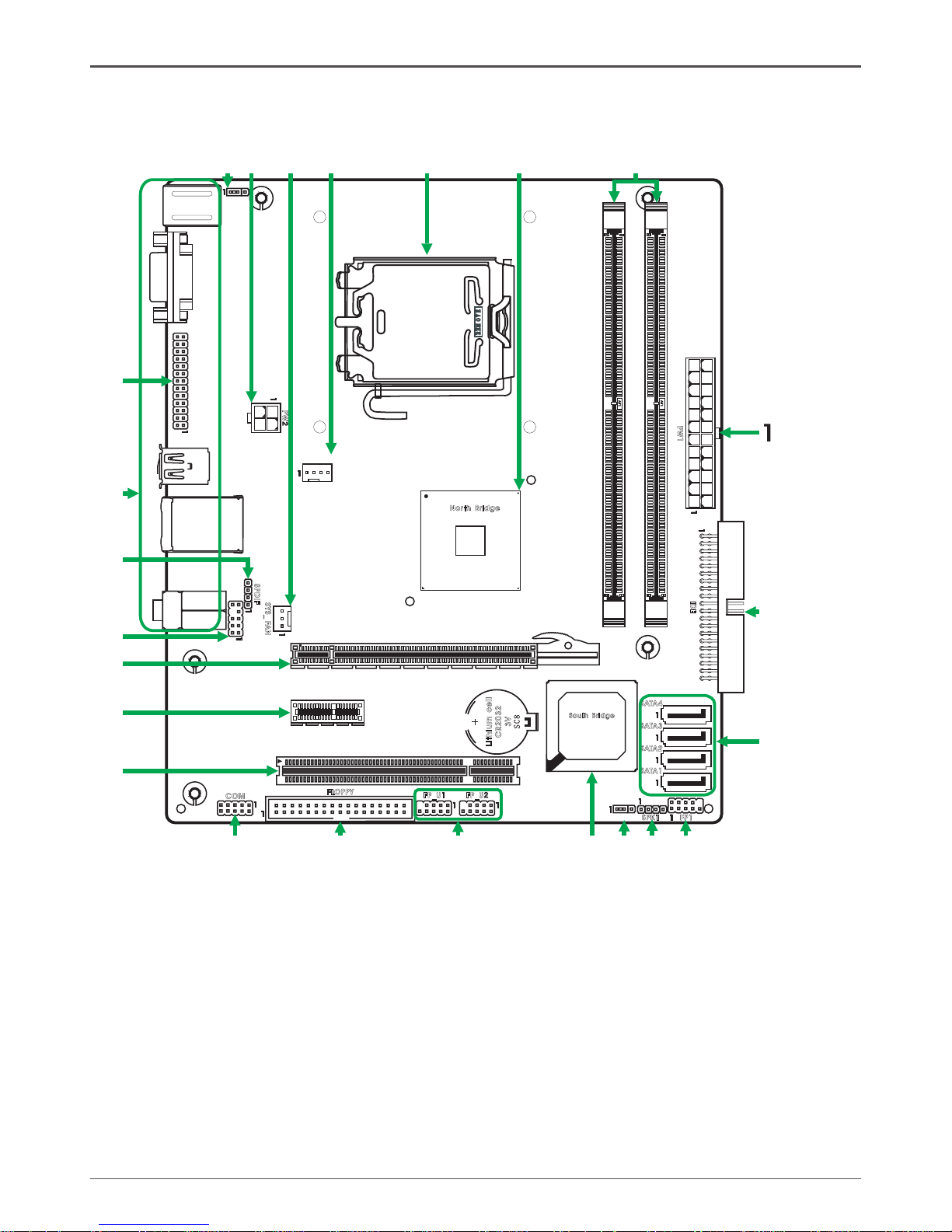
Motherboard Layout
Figure 1 shows the motherboard and Figure 2 shows the back panel connectors.
Figure 1. Board Layout
24-pin ATX Power Connector
IDE Connector
Serial-ATA (SATA) Connectors (Optional)
Front Panel Header
Speaker Header
Clear CMOS Jumper
South Bridge
USB Headers
Floppy Disk Drive Connector(Optional)
COM Port Header(Optional)
PCI Slots
PCIEx1 Slot(Optional)
1.
2.
3.
4.
5.
6.
7.
8.
9.
10.
11.
12.
PCI Express x16 Slot
Front Audio Header
SPDIF-Out Header
Backpanel Connectors
LPT Header(Optional)
Rear PS/2 Power Select Jumper(Optional)
4-pin ATX_12V Power Connector
System Fan Connector(Optional)
CPU Fan Connector
CPU Socket
North Bridge
DDRII DIMM Sockets
13.
14.
15.
16.
17.
18.
19.
20.
21.
22.
23.
24.
120
240
121
LO
TES
RE O EVM
Lit hi um
cel
l
CR2 03 2
3V
SC 8
120
240
121
JP2
LP
T
Nor th Bridg e
Sou th Br id ge
FP
S1
_
PW
2
SYS _
FA
N
PW
1
SPD I
F
COM
FP1
SPK 1
FP_ U2FP_ U1
IDE
JP1
S
ATA
4
FLO PPY
US
B
PCI 1
PCI E1
DDR II 1
KB1
DDR II 2
CUP FAN_
SD1
VG
A
US
B L
AN
_
S
ATA
3
S
ATA
2
S
ATA
1
PCI E2
12
2
3
4
5
6
7
8
9
10
11
13
14
15
16
17
18
19
20
21
22
23 24
Page 8
7
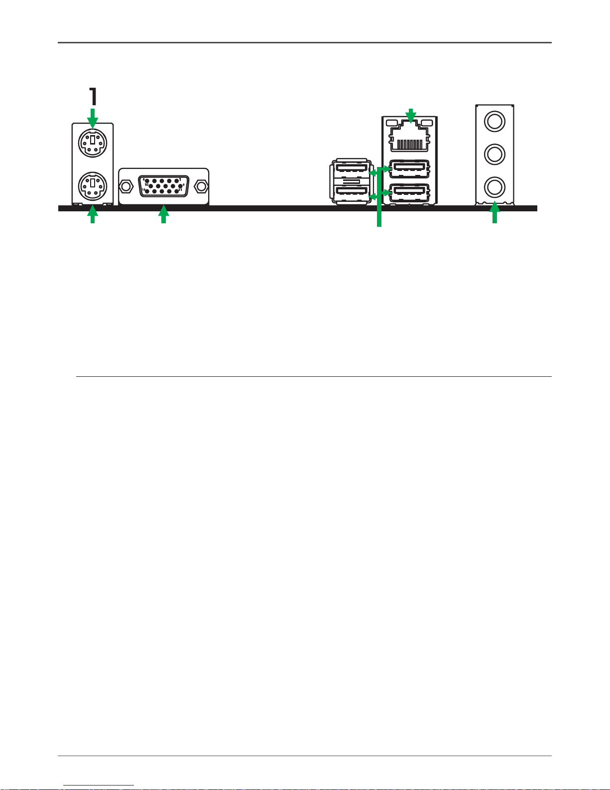
Rear Panel
1. PS/2 Mouse Port
2. PS/2 Keyboard Port
3. VGA Connector
4. USB Port
5. Port 2-Channel 4-Channel 6-Channel
Blue Line-In Rear Speaker Out Rear Speaker Out
Green Line-Out Front Speaker Out Front Speaker Out
Pink Mic In Mic In Center/Subwoofer
7. LAN Connector
Lan Port with LEDs to indicate status.
· Yellow/Light Up/Blink = 10 Mbps/Link/Activity
· Yellow and Green/Light Up/Blink = 100 Mbps/link/Activity
Figure 2: Backpanel connectors
6
11
5
10
15
2
3
4
5
6
Page 9

8
G31-Value series motherboard
Hardware Installation
This section will guide you through the installation of the motherboard. The topics
covered in this section are:
q Preparing the motherboard
v Installing the CPU
v Installing the CPU fan
v Installing the memory
q Installing the motherboard
q Connecting cables and setting switches
Safety Instructions
To reduce the risk of fire, electric shock, and injury, always follow basic safety precations.
Remember to remove power from your computer by disconnecting the AC main source
before removing or installing any equipment from/to the computer chassis.
Page 10
9
Hardware Installation
Preparing the Motherboard
The motherboard shipped in the box does not contain a CPU and memory. You need
to purchase these to complete this installation.
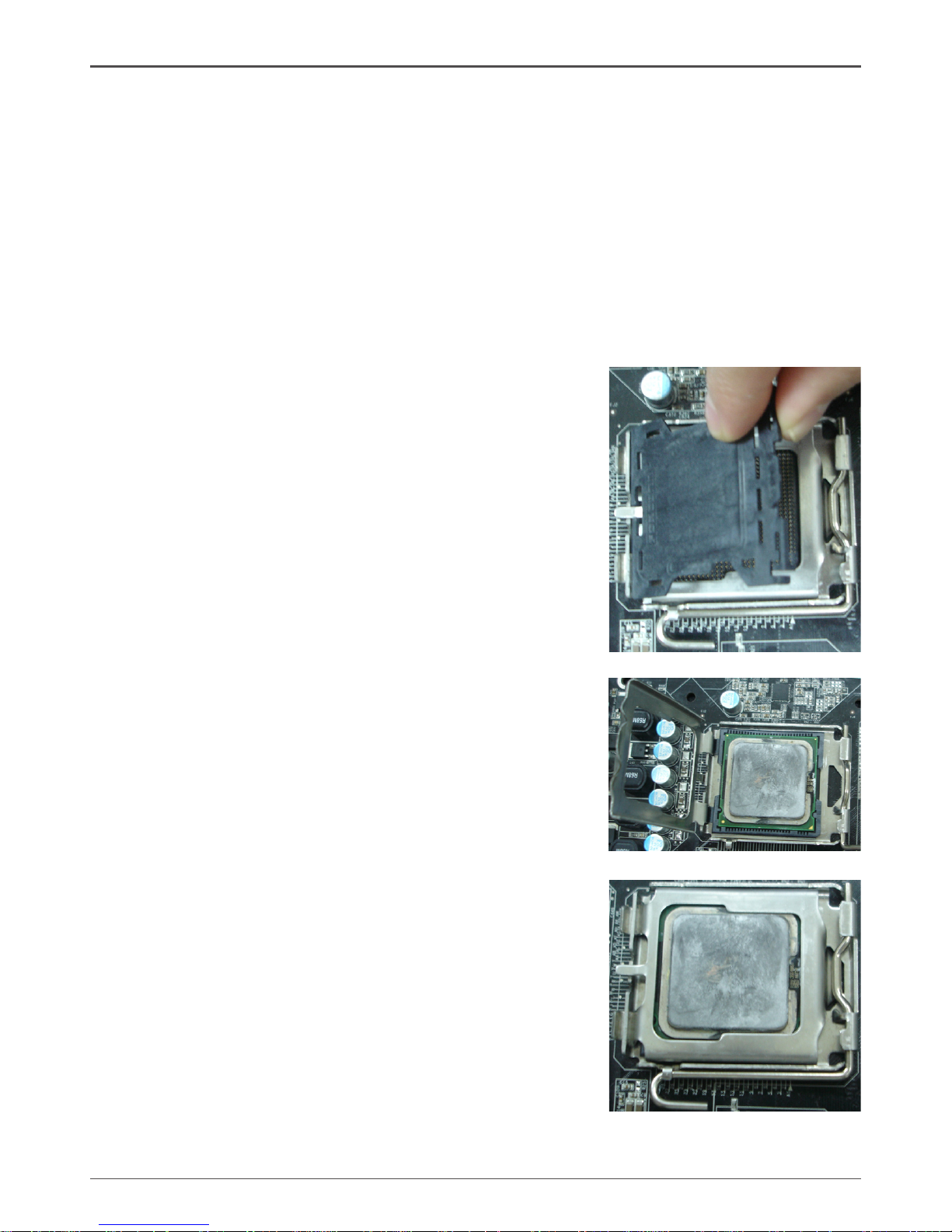
Installing the CPU
Be very careful when handling the CPU. Make sure not to bend or break any pins on
the back. Hold the processor only by the edges and do not touch the bottom of the
processor.
Use the following procedure to install the CPU onto the motherboard.
1. Unhook the socket lever by pushing down and
away from the socket.
2. Lift the load plate. There is a protective socket
cover on the load plate to protect the socket
when there is no CPU installed.
3. Remove the protective socket cover from the
load plate.
4. Remove the processor from its protective cover,
making sure you hold it only by the edges.
It is a good idea to save the cover so that
whenever you remove the CPU, you have a
safe place to store it.
5. Align the notches in the processor with the
notches on the socket.
6. Lower the processor straight down into the
socket with out tilting or sliding it into the socket.
Note: Make sure the CPU is fully seated and
level in the socket.
7. Close the load plate over the CPU and press
down while you close and engage the socket
lever.
Page 11
10
G31-Value series motherboard
120
240
121
LO
TES
RE O EVM
Lit hi um
cel
l
CR2 03 2
3V
SC 8
120
240
121
Installing the CPU Fan
There are many different fan types that can be used with this motherboard. Follow the
instruction that came with your fan assembly. Be sure that the fan orientation is correct
for your chassis type and your fan assembly.
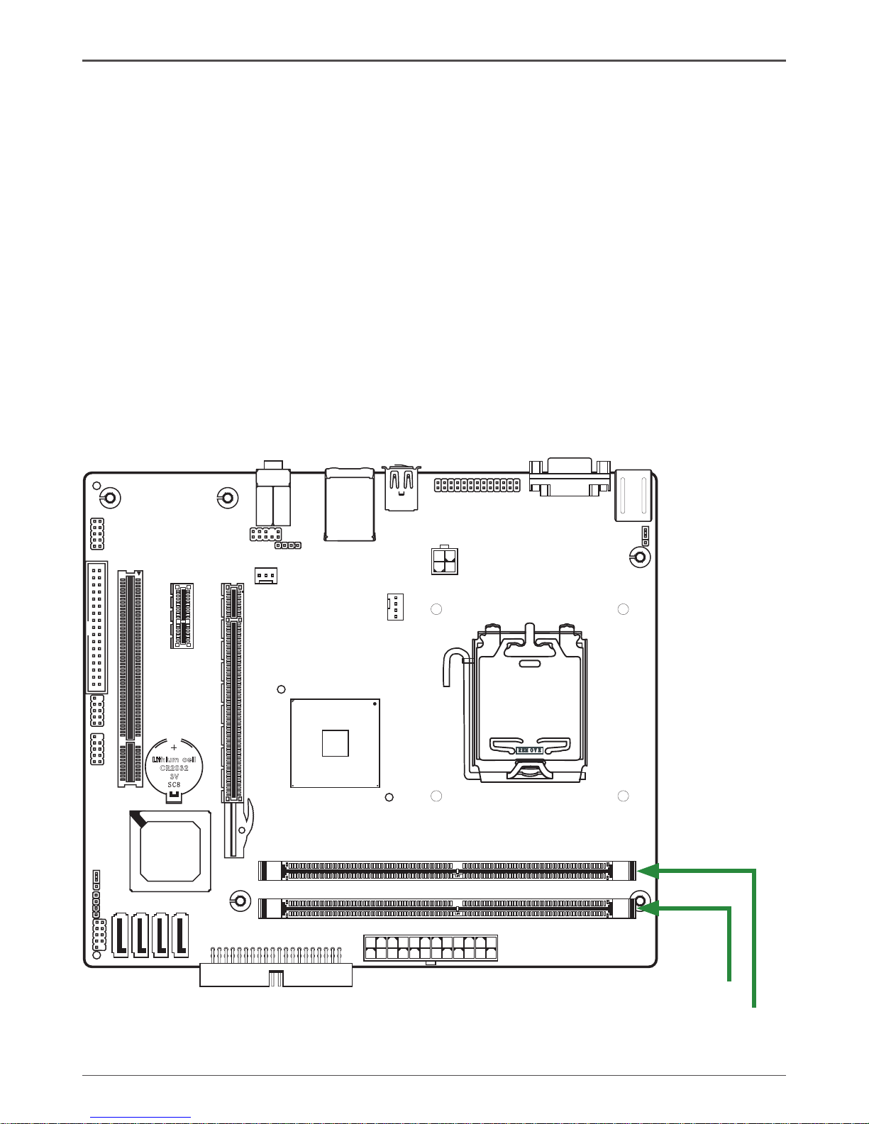
Installing Memory DIMMs
Your new motherboard has two 1.8V 240-pin slots for DDR2 memory. These slots
support 256 MB / 512 MB /1GB / 2GB / 4GB DDR2 technologies. There must be at
least one memory bank populated to ensure normal operation. Use the following the
recommendations for installing memory. (See Figure1 for the location of the memory
slots.)
q One DIMM: You can install the DIMM into any slot,however,slot 1 is preferred.
q Two DIMMs: Install into slots 1 and 2,The idea is to run on dual channel mode.
DDRII-2
DDRII-1
Page 12

11
Hardware Installation
Use the following procedure to install memory DIMMs into the slots on the motherboard. Note that there is only one gap near the center of the DIMM slot. This slot
matches the slot on the memory DIMM to ensure the component is installed properly.
1. Unlock a DIMM slot by pressing the module clips outward.
2. Align the memory module to the DIMM slot, and insert the module vertically into
the DIMM slot. The plastic clips at both sides of the DIMM slot automatically lock
the DIMM into the connector.
Installing the Motherboard
The sequence of installing the motherboard into the chassis depends on the chassis
you are using and if you are replacing an existing motherboard or working with an
empty chassis. Determine if it would be easier to make all the connections prior to this
step or to secure the motherboard and then make all the connections. It is normally
easier to secure the motherboard first.
Use the following procedure to install the I/O shield and secure the motherboard into
the chassis.
Note: Be sure that the CPU fan assembly has enough clearance for the
chassis covers to lock into place and for the expansion cards. Also
make sure the CPU Fan assembly is aligned with the vents on the
covers.
Installing the I/O Shield
The motherboard kit comes with an I/O shield that is used to block radio frequency
transmissions, protects internal components from dust and foreign objects, and
promotes correct airflow within the chassis.
Before installing the motherboard, install the I/O shield from the inside of the chassis.
Press the I/O shield into place and make sure it fits securely. If the I/O shield does
not fit into the chassis, you would need to obtain the proper size from the chassis
supplier.
Page 13

12
G31-Value series motherboard
Connecting Cables and Setting Switches
This section takes you through all the connections and switch settings necessary on
the motherboard. This will include:
q Power Connections
v 24-pin ATX power (PW1)
v 4-pin ATX 12V power (PW2)
q Connecting Internal Headers
v Hard Disk Connector - IDE
v SPK Header
v Serial Port Header - COM(Optional)
v Front panel header-FP1
v USB Headers(FP_U1~FP_U2)
v LPT Header(Optional)
v Floppy Disk Drive Connector(Optional)
v F_Audio Header
v SPDIF-Out Header
q Serial ATA II(Optional)
q Chassis Fans
q Expansion slots
q Jumper settings
See Figure 1 to locate the connectors and jumpers referenced in the following
procedure.
Page 14
13
120
240
121
LO
TES
RE O EVM
Lithi um
cel
l
CR203 2
3V
SC8
120
240
121
Hardware Installation
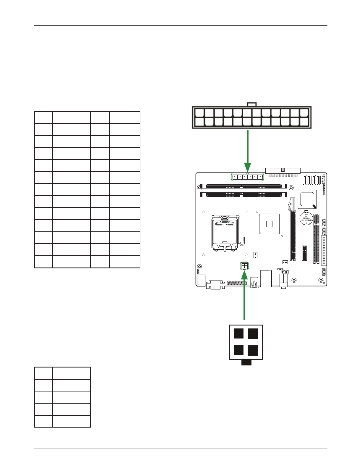
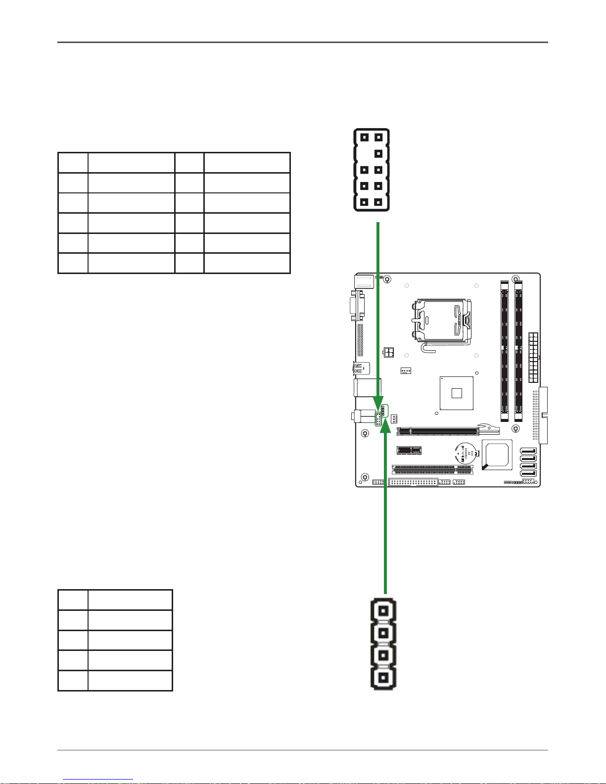
24-pin ATX Power (PW1)
PW1 is the main power supply connector located along the edge of the board next to
the DIMM slots. Make sure that the power supply cable and pins are properly aligned
with the connector on the motherboard. Firmly plug the power supply cable into the
connector and make sure it is secure.
112
13
24
4-pin ATX 12V Power (PW2)
PW2, the 4-pin ATX 12V power connection,
is used to provide power to the CPU. Align
the pins to the connector and press firmly
until seated.
1
2
3 4
PW1-Pin Definition
Pin Signal Pin Signal
1 +3.3V 13 +3.3V
2 +3.3V 14 -12V
3 GND 15 GND
4 +5V 16 PS_ON
5 GND 17 GND
6 +5V 18 GND
7 GND 19 GND
8 PWROK 20 -5V
9 +5V_AUX 21 +5V
10 +12V 22 +5V
11 +12V 23 +5V
12 +3.3V 24 GND
PW2-Pin Definition
Pin Signal
1 GND
2 GND
3 +12V
4 +12V
Page 15
14
G31-Value series motherboard
120
240
121
LO
TES
RE O EVM
Lith ium
cel
l
CR20 32
3V
SC 8
120
240
121
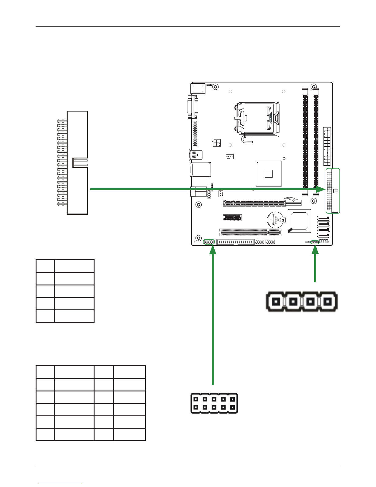
Hard Disk Connector - IDE
The motherboard has a 32-bit Enhanced PCI IDE and Ultra DMA 66/100/133 controller that provides PIO mode 0~4, Bus Master, and Ultra DMA 66/100/133 function. You
can connect up to two hard disk drives, CD-ROM, 120MB Floppy (reserved for future
BIOS) and other devices.
SPK Header
SPK
1
Serial Port Header - COM(Optional)
COM
1
2
9
10
SPK-Pin Definition
Pin Signal
1 VCC
2 NC
3 NC
4 SPK-
COM-Pin Definition
Pin Signal Pin Signal
1 DCD 6 DSR
2 RXD 7 RTS
3 TXD 8 CTS
4 DTR 9 RI
5 GND 10 NC
1
IDE
Page 16
15
Front panel header - FP1
The front panel header on this motherboard is one connector used to connect the
following four cables :
q PWRLED
Attach the front panel power LED cable to these two pins of the connector. The
Power LED indicates the system’s status.
Note: Some chassis do not have all four cables. Be sure to match the name on
the connectors to the corresponding pins.
q PWR SW
Attach the power button cable from the case to these two pins. Pressing the
power button on the front panel turns the system on and off rather than using the
power supply button.
q HDD LED
Attach the hard disk drive indicator LED cable to these two pins. The HDD
indicator LED indicates the activity status of the hard disks.
q RST SW
Attach the Reset switch cable from the front panel of the case to these two pins.
The system restarts when the RESET switch is pressed.
120
240
121
LO
TES
RE O EVM
Lith ium
cel
l
CR20 32
3V
SC 8
120
240
121
Hardware Installation
FP1
1
2
9
10
FP1-Pin Definition
Pin Signal Pin Signal
1 HDD_LED+ 6 PWR_SW
2 PW_LED+ 7 RESET
3 HDD_LED- 8 GND
4 PW_LED- 9 NC
5 GND 10 KEY
Page 17
16
G31-Value series motherboard
120
240
121
LOTES
RE O EVM
Lithi um
cel
l
CR203 2
3V
SC8
120
240
121
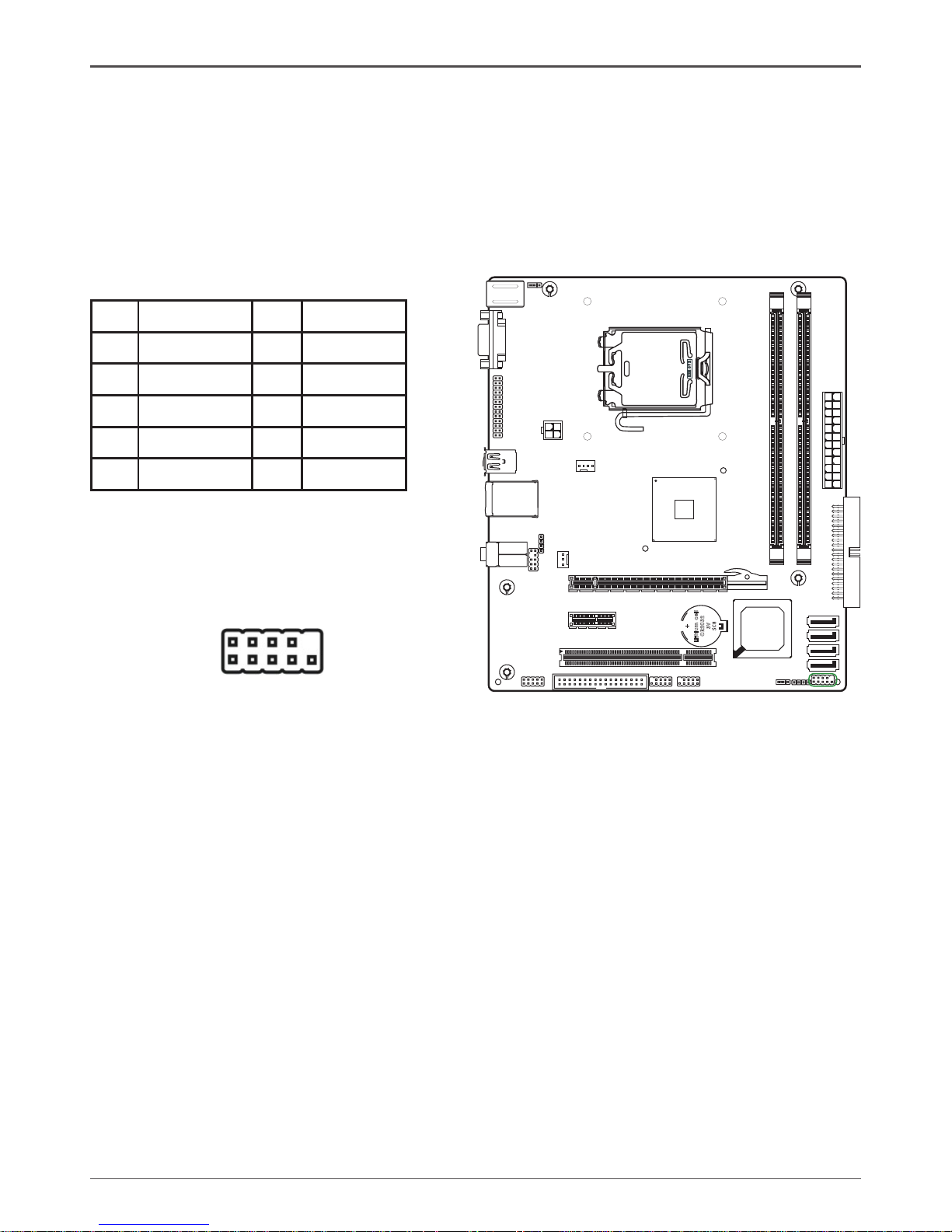
USB Headers(FP_U1~FP_U2)
This motherboard contains four USB 2.0 ports that are exposed on the rear panel of
the chassis(Figure 2). The motherboard also contains two 10-pin internal header connectors onboard.
1. Secure the bracket to either the front or rear panel of your chassis (not all chassis
are equipped with the front panel option).
Floppy Disk Drive Connector(Optional)
Floppy
1
USB-Pin Definition
Pin Signal Pin Signal
1 VCC 6 USBP1+
2 VCC 7 GND
3 USBP0- 8 GND
4 USBP1- 9 KEY
5 USBP0+ 10 OC#
19
10 2
FP_U1
19
10 2
FP_U2
The motherboard provides a standard floppy disk drive
connector that supports 360K, 720K, 1.2M, 1.44M and
2.88M floppy disk types.
LPT Header(Optional)
LPT - Pin Definition
1 STROBE 10 GND 19 ACK*
2 ALF* 11 PD4 20 GND
3 PD0 12 GND 21 BUSY
4 ERR* 13 PD5 22 GND
5 PD1 14 GND 23 PE
6 INIT* 15 PD6 24 GND
7 PD2 16 GND 25 SLCT
8 SCLTIN* 17 PD7 26 NC
9 PD3 18 GND
1
LPT
Page 18
17
Hardware Installation
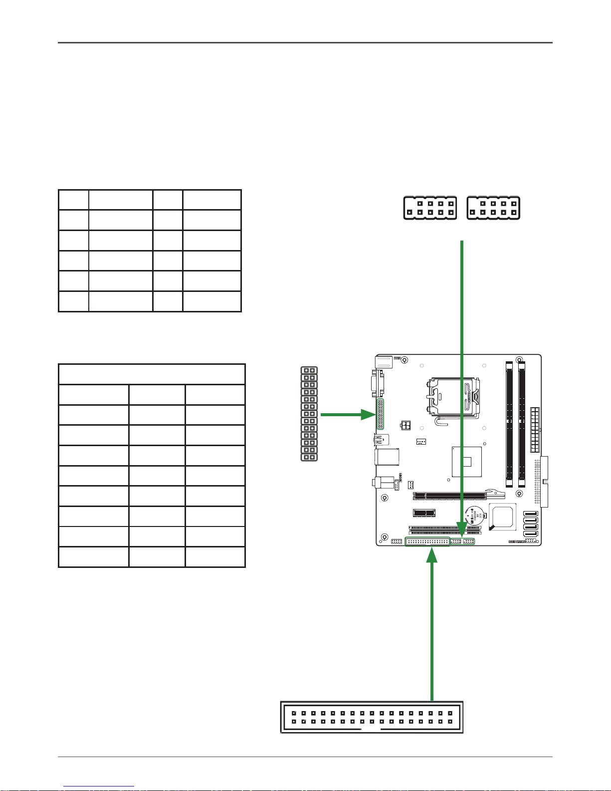
F_Audio Header
The audio connector supports HD audio standard and provides two kinds of audio
output choices: the Front Audio, the Rear Audio. The front Audio supports re-tasking
function.
Note:
In order to utilize the front audio header, your
chassis must have front audio connector. Also
please make sure the pin assignment on the
cable is the same as the pin assignment on the
mainboard header. To find out if the chassis you
are buying supports a front audio connector,
please contract your dealer.
120
240
121
LO
TES
RE O EVM
Lithi um
cel
l
CR203 2
3V
SC8
120
240
121
SPDIF-Out Header
This header provides a SPDIF (Sony/Philips
Digital Interface)output to digital multimedia
device through coaxial connector.
2
1
10
9
F_Audio
F_Audio-Pin Definition
Pin Signal Pin Signal
1 MIC(L) 6 Reserved
2 GND 7 FAVDIO-JD
3 MIC(R) 8 Key(No pin)
4 -ACZ-DET 9 Front Audio(L)
5 Front Audio(R) 10 Reserved
SPDIF-Pin Definition
Pin Signal
1 SPDIF OUTX
2 VCC
3 NC
4 GND
1
SPDIF
Page 19

18
G31-Value series motherboard
Connecting Serial ATA Cables(Optional)
The Serial ATA II connector(Two or Four ports) are used to connect the Serial ATA II
device to the motherboard. These connectors support the thin Serial ATA II cables for
primary storage devices. The current Serial ATA II interface allows up to 3GB/S data
transfer rate.
120
240
121
LO
TES
RE O EVM
Lith ium
cel
l
CR20 32
3V
SC8
120
240
121
SATA-2SATA-1 SATA-4SATA-3
1
Fan Connections
There is one or two fan connections on the
motherboard because SYS fan connector is
optonal. The fan speed can be detected and
viewed in the PC Health Status section of the
CMOS Setup.
CPU FAN Connector
GND
+12V
Sense
Control
SATA-Pin Definition
Pin Signal
1 GND
2 TXP
3 TXN
4 GND
5 RXN
6 RXP
7 GND
1
1
1
SYS FAN Connector(Optional)
Sense
+12V
GND
Page 20

19
PCI Slots
The one PCI slot support many expansion cards such as a LAN card, USB card, SCSI
card and other cards that comply with PCI specifications. When installing a card into
the PCI slot, be sure that it is fully seated. Secure the card’s metal bracket to the chassis back panel with the screw used to hold the blank cover.
PCI Express x16 Slots
There is one PCI Express x16 slot reserved for graphics or video cards. The bandwidth of the x16 slot is up to 4GB/Sec complianting with PCIE 1.1 specification.
When installing a PCI Express x16 card, be sure the retention clip snaps and locks
the card into place. If the card is not seated properly, it could cause a short across the
pins. Secure the card’s metal bracket to the chassis back panel with the screw used
to hold the blank cover.
PCI Express x1 Slots(optional)
There is one PCI Express x1 slot that is designed to accommodate less bandwidthintensive cards, such as a modem or LAN card. The x1 slot provides 500 MB/sec
bandwidth.
Expansion Slots
The Intel G31 motherboard contains three expansion slots, one PCI Express X16 slot
,one PCI Express X1 slot (Optional) and one PCI slot. For a full list of PCI Express x16
graphics card supported by this motherboard.
120
240
121
LO
TES
RE O EVM
Lit hium
cel
l
CR2 032
3V
SC 8
120
240
121
Hardware Installation
PCI Express x 1 slot(Optional)
PCI slot
PCI Express x 16 slot
Page 21

20
G31-Value series motherboard
JP2 Selection
1-2 5V power input
2-3* 5V standby power input*
Jumper Settings
This chapter explains how to configure the motherboard’s hardware. Before using your
computer, make sure all jumpers and DRAM modules are set correctly. Refer to this
chapter whenever in doubt.
Notice:
1. Be sure to save the CMOS setting when exit the CMOS.
2. If the CPU is frequency multiplier locked, no CPU speed change will be seen
even if the frequency multiplier setting in CMOS setup is changed.
Close Open * = Default setting.
JP1-CMOS Clear Jumper
1
1
JP2-P/S Port 5V Standby Power Selection(Optional)
JP1 Selection
1-2* Normal*
2-3 CMOS Clear
1
1
If you want to clear the system configuration,use the JP1(Clear CMOS Jumper) to clear date
Page 22

21
Configuring the BIOS
Conguring the BIOS
This section discusses how to change the system settings through the BIOS Setup
menus. Detailed descriptions of the BIOS parameters are also provided.
Enter BIOS Setup
The BIOS is the communication bridge between hardware and software. Correctly
setting the BIOS parameters is critical to maintain optimal system performance.
Use the following procedure to verify/change BIOS settings.
1. Power on the computer.,
2. Press the Del key when the following message briefly displays at the bottom of
the screen during the Power On Self Test (POST).
Press F1 to continue, DEL to enter Setup.
Pressing Del takes you to the Phoenix-Award BIOS CMOS Setup Utility.
Note: It is strongly recommended that you do not change the default BIOS
settings. Changing some settings could damage your computer.
If you do not find the setting you want in the Main Menu or a submenu, Press
<Ctrl>+<F1> to access more advanced options.
Page 23

22
G31-Value series motherboard
Main Menu
The main menu allows you to select from the list of setup functions and two exit
choices. Use the Page Up and Page Down keys to scroll through the options or press
Enter to display the associated submenu. Use the # $ arrow keys to position the
selector in the option you choose. To go back to the previous menu, press Esc.
q Standard CMOS Features
Use this menu to set up the basic system configuration.
q Advanced BIOS Features
Use this menu to set up the advanced system features and boot sequence.
q Advanced Chipset Features
Use this menu to optimize system performance.
q Integrated Peripherals
Use this menu to set up onboard peripherals such as IDE, RAID, USB and LAN
control.
q Power Management Setup
Use this menu to configure power management, power on, and sleep features.
q PnP/PCI Configurations
Use this menu to modify the system’s Plug-and-Play and PCI configurations.
q Pc health status
Use this menu to monitor the real-time system status of your PC.
q Frequency/Voltage control
Use this menu to adjust frequency/Voltage.
The following items on the CMOS Setup Utility main menu are commands rather
than submenus:
q Load Fail-Safe/Optimized Defaults
Load standard/optimized default system settings.
q Set Supervisor and User Password
Use this command to set, change, and disable the password used to access the
system and the BIOS menu.
q Save & Exit Setup
Use this command to save settings to CMOS and exit setup.
q Exit Without Saving
Use this command to abandon all setting changes and exit setup.
Note:
that on the BIOS screens all data in
white is for information only, data in
yellow is changeable, data in blue is
non-changeable, and data in a red
box is highlighted for selection.
Page 24

23
Configuring the BIOS
Note:
that all data in white is for
information only, data in yellow is
changeable, data in blue is nonchangeable, and data in a red box
is highlighted for selection.
Standard CMOS Features Menu
The Standard CMOS Features menu is used to configure the standard CMOS
information, such as the date, time, HDD model, and so on. Use the Page Up and
Page Down keys to scroll through the options or press Enter to display the sub-menu.
Use the # $ arrow keys to position the selector in the option you choose. To go back
to the previous menu, press Esc.
The information shown in Item Help corresponds to the option highlighted.
Date and Time
Using the arrow keys, position the cursor over the month, day, and year. Use the Page
Up and Page Down keys to scroll through dates and times. Note that the weekday
(Sun through Sat) cannot be changed. This field changes to correspond to the date you
enter. Note that the hour value is shown in a 24-hour clock format. Time is represented
as hour : minute : second.
IDE Channel
Use these functions to detect and configure the individual IDE channels. Select a
channel and press Enter to display the IDE sub-menu.
Press Enter to auto-detect IDE channels in the system. Once the channel is detected,
the values for Capacity, Cylinder, Head, Precomp, Landing Zone, and Sector are
automatically filled in.
q None
There is no HDD installed or set.
q Auto
The system can auto-detect the hard disk when booting up.
Video
Use this option to choose the mode of Video, as EGA/VGA, CGA 40, CGA 80,
MONO.
Page 25

24
G31-Value series motherboard
Drive A
The Drive A option allows you to select the kind of FDD to install.
Halt On
Halt On determines whether or not the computer stops if an error is detected during
power on. Use the Page Up and Page Down keys to scroll through the options or
press Enter to display the Halt On sub-menu. Use the # $ arrow keys to position
the selector in the option you choose. Press Enter to accept the changes and return
to the Standard CMOS Features menu.
q All Errors
Whenever the BIOS detects a nonfatal error, the system stops and prompts you.
q No Errors
System boot does not stop for any detected errors.
q All, But Keyboard
System boot does not stop for
keyboard errors, but does stop for all
other errors.
q All, But Diskette
The system boot does not stop for a diskette error but will stop for all other
errors.
q All, But Disk/Key
These field are read-only and are determined by the BIOS POST.
Memory
These settings are display-only values that are determined by the BIOS POST
(Power-On Self Test).
q Base Memory
BIOS POST determines the amount of base (or conventional) memory installed
in the system.
q Extended Memory
BIOS determines how much extended memory is present during the POST.
q Total Memory
This value represents the total memory of the system.
Page 26

25
Note:
that all data in white is for information
only, data in yellow is changeable,
data in blue is non-changeable, and
data in a red box is highlighted for
selection.
Advanced BIOS Features
Access the Advanced BIOS Features menu from the CMOS Utility Setup screen. Use
the Page Up and Page Down keys to scroll through the options or press Enter to
display the sub-menu. Use the # $ arrow keys to position the selector in the option
you choose. To go back to the previous menu, press Esc.
Note:
The options that have ssociated
sub-menus are designated by a u,
which precedes the option. Press
Enter to display the sub-menus.
Configuring the BIOS
CPU Feature
Press Enter to display CPU Feature menu,then the following items will be displayed:
q PPM Mode
Use this option to choose the mode of PPM.
q Limit CPUID MaxVal
Use this option to enable or disable the function of Limiting CPUID MaxVal
q C1E Function
Select CPU C1E function.
Page 27

26
G31-Value series motherboard
q Execute Disable Bit
When disabled forces the XD feature flag to always return 0, defaults choose
Enable.
q Virtualization Technoligy
Use this option to enable or disable CPU Virtualization Technoligy.
q Core Multi-Processing
Use this option to enable or disable Core Multi-Processing.
Hard Disk Boot Priority
Press Enter to display Hard Disk Boot Priority menu,then the following items will be
displayed:
q Bootable Add-in Cards
Use this option to bootable add-in cards.
q Virus Warning
Allow you to choose the Virus Warning feature for IDE Hard Disk boot sector
protection.
q CPU L1,L2 & L3 Cache
Use these options to disable or enable L1/L2/L3 cache.
q Quick Power On Self Test
Enabling this option allows the system to skip certain test while booting, which
reduces the time needed to boot the system.
q First/Second/Third Boot Device
Use this option to set the priority sequence of the devices booted at power on.
Use the Page Up and Page Down keys to scroll through the options or press
Enter to display the sub-menu. Use the # $ arrow keys to position the
selector in the option you choose.
q Boot Other Device
With the option set to Enable, the system boots from some other device if the
first/second/third boot devices fail.
q Swap Floppy Drive
if system have two floppy,you can enable the physical driver B for the logic driver
A.
q Boot Up Floppy Seek
Enabled tests floppy drives to determine whether they have 40 or 80 tracks.
q Boot Up NumLock Status
This option allows you to select the power-on state of NumLock. Select On
to activate the keyboard NumLock when the system is started. Select Off to
disable the NumLock key.
q Gate A20 Option
Use this option to choose Gate A20 menu.
q Typematic Rate Setting
Use this option to set keystrokes repeat. if Enabled, display options as follows:
v Typematic Rate
v Typematic delay
Page 28

27
Configuring the BIOS
q Security Option
The Security Options allows you to require a password every time the system
boots or only when you enter setup. Select Setup to require a password to gain
access to the CMOS Setup screen. Select System to require a password to
access the CMOS Setup screen and when the system boots.
q APIC Mode
Use this function to enable or disable the Advanced Programmable Interrupt
Controller (APIC). If you disable this option, you also disable the MPS Version
Control for OS option.
q MPS Version Control For OS
Use this function to select the Multi-Processor Specification (MPS) version that
BIOS passes to the operating system. Use the Page Up and Page Down
keys to scroll through the options.
q OS Select For DRAM >64MB
DRAM for loading OS need more than 64MB
q Report No FDD For WIN 95
OS need to report when you didn't connect FDD in WIN 95 OS
q Full Screen LOGO Show
This option allows you to enable or disable the display of the full-screen logo
when the system boots. Use the Page Up and Page Down keys to toggle
between Enable and Disable.
q Small LoGo (EPA) Show
This option allows you to enable or disable the display of the Small LoGo when
the system boots.
Page 29

28
G31-Value series motherboard
Advanced Chipset Features
Select Advanced Chipset Features from the CMOS Setup Utility menu and press
Enter to display the functions of the Advanced Chipset Functions menu.
q DRAM Timing Selectable
Use this option to select the model how to set DRAM timing
q System BIOS Cacheable
Use this option to enable or disable the System BIOS Cacheable
q Memory Hole At 15M-16M
Use this option to enable or disable memory hole at 15M-16M function
q PCI Express Root Port
Use this option to define PCI Express root port
q PEG/Onchip VGA Control
Use this option to choose PEG control or onchip VGA control
q On-Chip Frame Buffer Size
Use this option to set the frame buffer size
q DVMT Mode
Use this option to choose the DVMT or FIXED mode
q DVMT/FIXED Memory Size
Use this option to set the DVMT/FIXED memory size.
Page 30

29
Configuring the BIOS
Integrated Peripherals Menu
Select Integrated Peripherals from the CMOS Setup Utility menu and press
Enter to display the Integrated Peripherals menu.
q OnChip IDE Device
Use this option to set on chip IDE function
q Onboard Device
Use this option to enable or disable Azalia/AC97 Audio Select
q Super IO Device
Use this option to set power on function ,onboard serial port and onboard parallel
port,and so on.
q USB Device Setting
Use this option to set USB device
Page 31

30
G31-Value series motherboard
Power Management Setup Menu
Select Power Management Setup from the CMOS Setup Utility menu and press
Enter to display the Power Management Setup menu.
q PCI Express PM Function
Use this option to enable or disable Root port ASPM ,DMI port ASPM,and so on.
q ACPI Function
This function on the Power Management Setup menu allows you to enable or
disable the ACPI function.
q ACPI Suspend Type
Use this option to choose ACPI suspend type
q Run VGABIOS if S3 Resume
Use this option to set the type of running VGABIOS
q Power Management
Use this option to set the mode for Power Management.
Page 32

31
Configuring the BIOS
q Video Off Method
Use this option to set a Method for Video off.
q Video Off In Suspend
Use this option to set the type of video off in suspend.
q Suspend Type
Use this option to choose suspend type.
q MODEM Use IRQ
Use this option to set the mode of using IRQ.
q Suspend Mode
Use this option to set suspend mode.
q HDD Power Down
Use this option to enable or disable a mode of HDD Power down.
q Soft-Off by PWR-BTTN
This function on the Power Management Setup menu allows you to set Soft-Off.
by PWR-BTTN to [Instant-Off] or [Delay 4 Sec].
q CPU THRM-Throttling
Use this option to set rate of CPU THRM-Throttling.
q Wake-Up By PCI card
Use this option to enable or disable wake-up by PCI card.
q Power On by Ring
Use this option to enable or disable power on by ring.
q USB KB Wake-Up From S3
Use this option to enable or disable USB KB Wake-up from S3.
q Resume by Alarm
Determines whether to power on the system at a desired time. If enable set the
date and time as following:
v Date(of Month) Alarm: Tarn on the system at a specific time on each day or
on a specific day in a month.
v Time(hh:mm:ss) Alarm: Set the time at which the system will be Powered
on automatically.
q Reload global timer events
Use this option to enable or disable remember the timer event of reloading
Primary/Secondary IDE 0/1, FDD,COM , and so on.
q HPET Support
Use this option to enable or disable HPET Support; if enable, HPET Mode
display. We can select.
q WDRT Mode
Use this option to enable or disable WDRT support.
Page 33

32
G31-Value series motherboard
PnP/PCI Congurations
Select PnP/PCI Conguration from the CMOS Setup Utility menu and press
Enter to display the PnP/PCI Configuration menu.
q Init Display First
This function on the PnP/PCI Configuration menu allows you to define if the initial
display is in the PCI slot, onboard or PCI Express slot. Options are [PCI Slot],
[Onboard] and [PCIEx].
q Reset Configuration Data
This function on the PnP/PCI Configuration menu allows you to enable or
disable the resetting of Extended System Configuration Data (ESCD) when
you exit Setup. Set this to [Enabled] if you have installed a new add-on and
the system reconfiguration has caused a serious conflict that prevents the OS
from booting. The default setting is [Disabled].
q Resources Controlled By
This function on the PnP/PCI Configuration menu allows you to define if the
BIOS can automatically configure all the boot and plug-and-play compatible
devices or if you can manually select IRQ, DMA, and memory base address
fields. Select [Auto(ESCD)] if you want the BIOS to automatically populate
these fields. If you select [Manual] so you can assign the resources, IRQ
Resources is enabled for input.
q IRQ Resources
To enable this field for input, set Resources Controlled By to [Manual].
With this field enabled, press Enter to see options.
Use Legacy ISA for devices compliant with the original PC AT Bus specification.
Use PCI/ISA PnP for devices compliant with the plug-and-play standard, whether
designed for PCI or ISA Bus architecture.
q PCI/VGA Palette Snoop
This function on the PnP/PCI Configuration menu allows you to enable or disable
the Palette Snoop function.
Page 34

33
q INT pin 1/2/3/4/5/6/7/8 Assignment
Use these options to set the mode of INT pin 1/2/3/4/5/6/7/8 Assignment
q Maximum Payload Size
This function on the PnP/PCI Configuration menu allows you to set the maximum
TLP payload size (in bytes) for the PCI Express devices. Use the Page Up
and Page Down keys to scroll through sizes or enter the number using
the keyboard numbers or use the + and – keys to go up and down the list of
sizes.
PC health Status
Select PC health Status from the CMOS Setup Utility menu and press Enter to
display the System Monitor menu.
q Shutdown Temperature
Use this option to set shutdown temperature
q CPU Fan Speed Control
Use this option to control the CPU fan speed
All of the values shown in are dynamic
and change as the speed and voltages
of the various components change
with system usage.
Configuring the BIOS
Page 35

34
G31-Value series motherboard
Frequency/Voltage Control
Select Frequency/Voltage Control from the CMOS Setup Utility menu and press Enter
to display the system Monitor menu.
q CPU Clock Ratio Unlock
Use this option to set the ratio of CPU clock
q Auto detect PCI Clk
Use this option to Enabled or Disable Auto detect PCI Clock
q Spread Spectrum
Use this option to Enabled or Disable Spread Spectrum
q CPU Clock
Use this option to set CPU clock
q DDR2 Voltage
Use this option to set DDR2 Memory voltage
q CHIPSET Voltage
Use this option to set chipset voltage
Load Fail-Safe/Optimized Defaults
Press <Enter> on the item “Load Fail-Safe Defaults” or “Load Optimized Defaults” and
then press the <Y> key to load the optimal BIOS default settings. The BIOS defaults
settings helps the system to operate in optimum state. Always load the standard or
Optimized defaults after updating the BIOS or after clearing the CMOS values.
Page 36

35
Configuring the BIOS
Set Supervisor/User Password
Press <Enter> on this item and type the password with up to 8 characters and then
press <Enter>. You will be requested to confirm the password. Type the password
again and press <Enter>.
The BIOS Setup program allows you to specify two separate passwords:
v Supervisor Password
When a system password is set and the Password Check item in Advanced
BIOS Features is set to Setup, you must enter the supervisor password for enter-
ing BIOS Setup and making BIOS changes.
When the Password Check item is set to System, you must enter the supervisor
password (or user password) at system startup and when entering BIOS Setup.
v User Password
When the Password Check item is set to System, you must enter the supervisor
password (or user password) at system startup to continue system boot. In BIOS
Setup, you must enter the supervisor password if you wish to make changes to
BIOS settings. The user password only allows you to view the BIOS settings but
not to make changes.
Page 37

36
G31-Value series motherboard
Save & Exit Setup
Press <Enter> on this item and press the <Y> key. This saves the changes to the
CMOS and exits the BIOS Setup program. Press <N> or <Esc> to return to the BIOS
Setup Main Menu.
Exit Without Saving
Press <Enter> on this item and press the <Y> key. This exits the BIOS Setup without
saving the changes made in BIOS Setup to the CMOS. Press <N> or <Esc> to return
to the BIOS Setup Main Menu.
To clear the password, press <Enter> on the password item and when requested
for the password, press <Enter> again. The message “PASSWORD DISABLED” will
appear, indicating the password has been cancelled.
Page 38

37
Warning : - Do not turn off or RESET the computer during the flash process.
- If you are not sure how to upgrade the BIOS, please take your
computer to an Authorized Service Center and have a trained
technician do the work for you.
Configuring the BIOS
FLASH Update Procedure
The program AWDFLASH.EXE is included on the driver CD (D:\Utility\
AWDFLASH.EXE). Please follow the recommended procedure to update the flash
BIOS, as listed below.
1. Create a DOS-bootable floppy diskette. Copy the new BIOS file (just obtained or
downloaded) and the utility program AWDFLASH.EXE to the diskette.
2. Allow the PC system to boot from the DOS diskette.
3. At the DOS prompt, type
AWDFLASH<ENTER>
4. Enter the file name of the new BIOS.
5. The question: “Do you want to save BIOS (Y/N)?” is displayed.
Press “N” if there is no need to save the existing BIOS.
Press “Y” if a backup copy of the existing BIOS is needed.
(A file name has to be assigned to the existing BIOS binary
file.)
6. The message : “Press “Y” to program or “N” to exit” is displayed. Type
“Y”<ENTER>
7. Wait until the flash-update is completed.
8. Restart the PC.
Page 39

38
G31-Value series motherboard
Installing Drivers and Software
Note: It is important to remember that before installing the driver CD that is
shipped in the kit, you need to load your operating system. The
motherboard supports Windows XP 32bit and 64bit and is Vista-capable.
The kit comes with a CD that contains utility drivers and additional software.
The CD that has been shipped with your Intel G31 motherboard contains the following
software and drivers:
q Software Installation Utility
q Intel Graphics Driver
q HDA sound Driver
q RTL8101E PCIE network Driver
Page 40

39
Drivers Installation
1. Insert the Intel G31 driver CD after loading your operating system.
Waiting for one menute you can see below interface.
2. Follow the below for Software Installation Utility Installing.
Installing Drivers and Software
Page 41

40
G31-Value series motherboard
Page 42

41
Installing Drivers and Software
3. Follow the below for Intel graphics drive Installing.
Page 43

42
G31-Value series motherboard
Page 44

43
Installing Drivers and Software
4. Follow the below for HDA sound driver installing.
Page 45

44
G31-Value series motherboard
5. Follow the below for RTL8101E PCIE network driver installing.
Page 46

45
Installing Drivers and Software
Page 47

46
G31-Value series motherboard
At last, you can open below page that provides information about the hardware devices on this motherboard, and check whether finish your installation.
Page 48

47
Realtek HD Audio Driver Setup
Getting Started
After Realtek HD Audio Driver being installed (insert the driverCD and follow the onscreen instructions), “Realtek HD Audio Manager” icon will show in System tray as
below. Double click the icon and the control panel will appear:
Sound Effect
After clicking on the “Sound Effect” tab, 3 sections “Environment”, “Equalizer” and
“Karaoke” are available for selection.
Environment Simulation
You will be able to enjoy different sound experience by pulling down the arrow, totally
23 kinds of sound effect will be shown for selection. Realtek HD Audio Sound Manager
also provides five popular settings “Stone Corridor”, “Bathroom”, “Sewer pipe”, “Arena”
and “Audio Corridor” for quick enjoyment.
Installing Drivers and Software
Page 49

48
G31-Value series motherboard
Equalizer Selection
The Equalizer section allows you to create your own preferred settings by utilizing
this tool.
In standard 10 bands of equalizer, ranging from 100Hz to 16KHz are available:
Frequently Used Equalizer Setting
Realtek recognizes the needs that you might have. By leveraging our long experience
at audio field, Realtek HD Audio Sound Manager provides you certain optimized equalizer settings that are frequently used for your quick enjoyment.
How to Use
Other than the buttons “Pop” “Live” “Club” & “Rock” shown on the page, to pull down
the arrow in “Others” , you will find more optimized settings available to you.
Karaoke Mode
Karaoke mode brings Karaoke fun back home by simply using the music you usually
play, Karaoke mode can help you eliminate the vocal of the song or adjust the key to
accommodate your range.
Vocal Cancellation: Single click on “Voice Cancellation”, the vocals of the songs will
be erased, while the background music is still playing which lets you take over the vocal
part.
Key Adjustment: Using “Up / Down Arrow” to find a key which better fits your vocal
range.
Page 50

49
Installing Drivers and Software
Mixer
Realtek HD Audio Sound Manager integrates Microsoft’s “Volume Control” functions
into the Mixer page. This gives you the advantage to you to create your favorite sound
effect in one single tool.
Playback control
Mute
You may choose to mute single or multiple volume controls or to completely mute
sound output.
Tool
√ Show the following volume control
This is to let you freely decide which volume control items to be displayed, total
13 items to be chosen.
√ Advanced controls
√ Enable playback multi-streaming
Page 51

50
G31-Value series motherboard
With this function, you will be able to have an audio chat with your friends via headphone
(stream 1 from front panel) while still have music (stream 2 from back panel) playing.
At any given period, you can have maximum 2 streams operating simultaneously.
Recording control
Mute
You may choose to mute single or multiple volume controls or to completely mute
sound input.
Tool
√
Show the following volume controls
This is to let you freely decide which volume control items to be displayed.
√ Advanced controls.
Advanced control is a “Microphone Boost” icon.
Once this item is checked, you will find “advanced” icon beside “Front Pink In” &
“Mic Volume”. With this, the input signal into “Front Pink In” & “Mic Volume” will
be strengthen.
√ Enable recording multi-streaming
At any given period, you can have maximum 2 streams operating simultaneously.
Page 52

51
Installing Drivers and Software
Audio I/O
Realtek HD Audio Manager frees you from default speaker settings. Different from
before, for each jack, they are not limited to perform certain functions. Instead, now
each jack is able to be chosen to perform either output (i.e. playback) function or input
(i.e. Recording) function, we call this “Retasking”.
Audio I/O aims to help you setting jacks as you wish. Moreover, other than blue to blue,
pink to pink, the way that you used to do, Audio I/O would guide you to other right jacks
that can also serve as microphone / speaker / headphone.
Page 53

52
G31-Value series motherboard
Speaker Configuration
Step 1: Plug in the device in any available jack.
Step 2: Dialogue “connected device” will pop up for your selection. Please select the
device you are trying to plug in.
* If the device is being plugged into the correct jack, you will be able to find the icon
beside the jack changed to the one that is same as your device.
* If not correct, Realtek HD Audio Manager will guide you to plug the device into the
correct jack.
Page 54

53
Installing Drivers and Software
Connector Settings
Click to access connector settings
√ Mute rear panel when front headphone plugged in
Once this option is checked, whenever front headphone is plugged, the music
that is playing from the back panel, will be stopped.
√ Disable front panel jack detection (option)
Did not find any function on front panel jacks?
Please check if front jacks on your system are so-called AC’97 jacks. If so,
please check this item to disable front panel jack detection.
√ Enable auto popup dialogue, when device has been plugged in.
Once this item checked, the dialog “Connected device”, would not automatically
pop up when device plugged in.
S/PDIF
Short for Sony/Philips Digital Interface, a standard audio file transfer format. S/PDIF
allows the transfer of digital audio signals from one device to another without having
to be converted first to an analog format. Maintaining the viability of a digital signal
prevents the quality of the signal from degrading when it is converted to analog.
Page 55

54
G31-Value series motherboard
√
Output Sampling Rate
- 44.1KHz: This is recommended while playing CD
- 48KHz: This is recommended while playing DVD or Dolby.
- 96KHz: This is recommended while playing DVD-Audio.
√
Output Source
- Output digital audio source: The digital audio format (such as .wav, .mp3,
.midi etc) will come out through S/PDIF-Out.
Speaker Calibration
After you have successfully plugged in speakers and assigned to the right jacks, you are
only one more step to go to enjoy the intended sound. We provide “Speaker Calibration”
to help you check if the speakers are located in the correct position.
Page 56

55
Installing Drivers and Software
Microphone
This page is designed to provide you better microphone / recording quality.
Below picture indicates both “Noise Suppression” & “Acoustic Echo
Cancellation” are both enabled.
Noise Suppression
If you feel that the background noise, especially the sound generated from the fan
inside PC, is too loud? Try “Noise Suppression”, which allows you to cut off and suppress disturbing noise.
Beam Forming
Also known as “directional recording”, this option lets you do the following: Once beam
forming is enabled; only the sound from certain direction will be recorded. You will get
the best quality if you chose 90° position, which we recommend you to use, this effectively means that you speak right into the microphone.
Note: A Stereo Microphone is required when using Beam Forming function.
Acoustic Echo Cancellation
This function prevents playback sound from being recorded by microphone together
with your sound. For example, you might have chance to use VOIP function through
Internet with your friends. The voice of your friend will come out from speakers (playback). However, the voice of your friend might also be recorded into your microphone
then go back to your friend through Internet. In that case, your friend will hear his/her
own voice again. With AEC (Acoustic Echo Cancellation) enabled at your side, your
friend can enjoy the benefit with less echo.
Page 57

56
G31-Value series motherboard
Audio Demo
The section “3D Audio Demo” grants you another possibility to enjoy your sound. The
Audio Demo allows you to listen to sound in an extraordinary way.
Information
This section provides information about your current system audio device.
291-MA111-01
Page 58

 Loading...