


Online Reference
© 2017 ZOOM CORPORATION
Copying or reprinting this manual in part or in whole without permission is prohibited.
Product names, registered trademarks and company names in this document are the property of their
respective companies. All trademarks and registered trademarks in this document are for identification
purposes only and are not intended to infringe on the copyrights of their respective owners.

Introduction
Thank you very much for purchasing a ZOOM LiveTrak L-12 ( ). The has the
following features.
12-channel digital mixer & multitrack recorder
The combines a digital mixer with 12 total input channels (8 mono and 2 stereo),
a multitrack recorder that can simultaneously record up to 14 tracks, and a 14-in/4-out
USB audio interface. Compact and lightweight, this digital mixer is easy to transport and
can even be used with PA systems for live performances in rehearsal studios, cafés and
other small venues.
High-quality mic preamps
The has high-quality mic preamps built-in for 8 channels. The high-quality analog inputs, which can provide +48V phantom power, have a −128dBu or better EIN rating
and +60dB maximum input gain. In addition, channels 1 and 2 also support Hi-Z input,
while channels 3 to 8 have PAD functions (26dB attenuation), enabling them to accept
high levels of input.
5 MONITOR OUT channels
In addition to the MASTER OUT, the also has 5 MONITOR OUT channels. The
MONITOR OUT mixes can be set separately for each output. Since these support head-
phone output, headphones are all that are needed to send different mixes to each performer.
Digital mixer that can be operated intuitively
Opening menus is not necessary with the . Every mixer parameter can be controlled with knobs and keys just like an analog mixer. Each channel has a 3-band EQ,
and the mono channels have compressor functions. The mixer also includes high-quality
send effects. In addition, up to 9 mixer status scenes can be saved in the unit.
Recorder can simultaneously record 14 tracks and play 12 tracks
The can simultaneously record every channel and the master fader stereo signal
output for a total of 14 tracks. Since the recorded data is saved in 16/24-bit, 44.1/48/96kHz
WAV format, the les can easily be copied to a computer and used in a DAW. In addition,
overdubbing and punching in/out can be done as expected with a multitrack recorder.
14-in/4-out USB audio interface
The can be used as a 14-in/4-out USB audio interface. The signals from each input and the master fader output can be recorded in a DAW. In addition, signals output
from a computer can also be assigned to a stereo channel.
Class compliant mode, which enables connection with iOS devices, is also supported.
2

Contents
Introduction ………………………… 2
Contents …………………………… 3
Names and functions of parts … 5
Top ………………………………… 5
Rear panel ……………………… 14
Equipment connection example 15
Live PA system ………………… 15
Display overview ……………… 17
Home Screen ………………… 17
Turning the unit on/off ………… 18
Turning the unit on …………… 18
Turning the power off ………… 20
Using the MENU screen ……… 21
Mixer ……………………………… 22
Outputting input sounds from
output devices ………………… 22
Adjusting the tone and
panning ………………………… 24
Using the built-in effects ……… 25
Using scene functions ………… 27
Setting signals output from
MONITOR OUT A–E …………… 30
Recording and playback ……… 32
Preparing to record …………… 32
Recording and playing tracks … 34
Adding marks ………………… 37
Redoing parts of recordings
(punching in/out) ……………… 38
Mixing down tracks …………… 40
Recording automatically ……… 42
Capturing audio before recording
starts …………………………… 44
Selecting the folder where projects
are saved ……………………… 45
Selecting projects for playback 46
Using the metronome ………… 47
Enabling the metronome ……… 47
Changing metronome
settings ………………………… 48
Using the slate mic …………… 52
Recording with the slate mic … 52
Changing slate mic settings … 53
Projects …………………………… 55
Changing project names ……… 55
Deleting projects ……………… 57
Protecting projects …………… 58
Checking project information … 59
Saving projects to USB ash
drives …………………………… 60
Importing projects from USB ash
drives …………………………… 63
Managing marks ……………… 65
Audio les………………………… 66
Deleting audio les …………… 66
Exporting audio les to USB ash
drives …………………………… 68
Importing audio les from USB ash
drives …………………………… 70
Using audio interface functions 72
Installing the driver …………… 72
Connecting to a computer …… 73
Inputting return signals from the
computer to a stereo channel ……74
Using card reader functions … 75
Recording and playback
settings …………………………… 76
Changing the recording format 76
Changing automatic recording
settings ………………………… 77
3

Introduction
Showing recording levels on level
meters ………………………… 79
Enabling latency adjustment … 79
Changing the playback mode … 80
SD card settings ………………… 81
Checking the open space on SD
cards …………………………… 81
Formatting SD cards ………… 81
Testing SD card performance … 82
Various settings ………………… 84
Setting the date and time …… 84
Setting the footswitch ………… 85
Changing the sampling rate … 86
Disabling the automatic power
saving function ………………… 87
Adjusting the display
contrast ………………………… 88
Restoring settings to factory
defaults ……………………… 88
Checking the rmware
versions. ………………………… 89
Updating the rmware ……… 90
Troubleshooting ………………… 91
Specications …………………… 93
Send effects specications …… 94
Mixer block diagram …………… 95
4

Names and functions of parts
⑩
⑪
⑫
⑬
⑮
⑭
To p
Input channel section
MIC/LINE input jack
1
These input jacks have built-in mic preamps. Connect mics, keyboards and guitars to them.
①
②
③
④
⑤
⑥
⑦
⑧
⑨
These can be used with both XLR and 1/4-inch (balanced or unbalanced) phone plugs.
48V switch/indicator
2
This turns 48V phantom power on or off. Turn this on (
phantom power to MIC/LINE input jacks 1–4 (or 5–8).
The indicator lights when the switch is on.
Hi-Z switch
3
Use to switch the input impedance of MIC/LINE input jack 1 (or 2).
Turn it on (
PAD switch
4
This attenuates (reduces) the input signal of the equipment connected
to the MIC/LINE input jack by 26 dB.
Turn this on (
SIG indicator
5
This indicator shows the signal level after adjustment by the GAIN knob.
The indicator color changes according to the signal level.
Lit red: −3 dB
Lit green: −48 to −3 dB
Blinking green: −55 to −48 dB
GAIN knob
6
Use to adjust the input gain of the mic preamp.
The range of adjustment depends on the on/off status of the MIC/LINE
input jack switch (Hi-Z on channels 1–2 or PAD on channels 3–8).
MIC/LINE input jack 1–2 (XLR) +16 – +60 dB
MIC/LINE input jack 1–2 (TRS) Hi-Z off +16 – +60 dB
MIC/LINE input jack 3–8 PAD off +16 – +60 dB
COMP knob
7
Use to adjust the amount of compression.
SEL button
8
Use to select a channel for parameter adjustment in the channel strip section.
Channels with lit SEL buttons are affected by channel strip section adjustments.
REC/PLAY button
9
Use this button to switch between recording input signals to the SD
card and playing back an already recorded le from the SD card.
Status Explanation
Lit red Input signals will be recorded to the SD card after passing
Lit green
Unlit Files will neither be recorded nor played back.
) when connecting a guitar or bass guitar.
) when connecting line level equipment.
Jack Adjustment range
through the compressor.
An already recorded le will be played back. Playback signals are input
before the equalizer. In this state, signals from input jacks are disabled.
5
Hi-Z on (TS) +6 – +50 dB
PAD on -10 – +34 dB
) to supply
Names and functions of parts
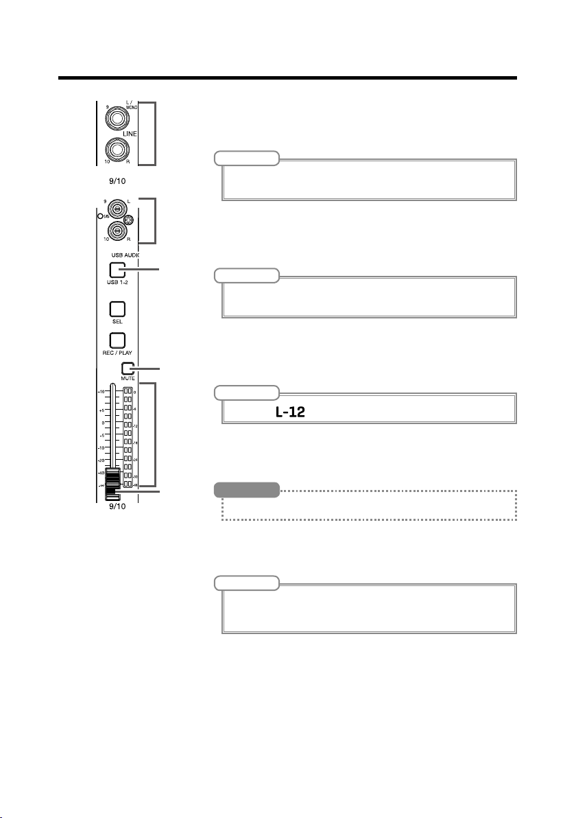
LINE input jacks (TS)
!
Use these input jacks to connect line level equipment. For example,
⑩
⑪
⑫
⑬
⑭
⑮
connect keyboards or audio devices.
These can be used with 1/4-inch (unbalanced) phone plugs.
LINE input jacks (RCA)
"
Use these input jacks to connect line level equipment. For example,
connect audio devices.
These can be used with RCA pin connectors.
USB button
#
This switches the signals input to channels 9/10 (or 11/12).
Lit: audio return signal output from the computer
Unlit: LINE input jacks
MUTE button
$
This mutes or unmutes signals sent to the master fader.
To mute the channel, press this button to light it.
NOTE
If only the left LINE input jack (TS) channel is connected, it will be handled as
a mono channel.
NOTE
If both the RCA and TS LINE input jacks are connected, the TS input jacks
will be used.
NOTE
Connect the to a computer as an audio interface. (→ P.73)
HINT
This has no effect on recording to the SD card.
Level meter
%
This shows the signal level after adjustment by the channel fader.
Ranges shown: -48 dB – 0 dB
NOTE
If the actual channel fader position differs from the channel fader position
recalled using the scene function, for example, the level meter will show the
recalled fader position.
Channel fader
&
This adjusts the channel signal level in a range from −∞ to +10 dB.
6

Names and functions of parts
②
③
④
⑤
⑥
⑧
CHANNEL STRIP section
①
⑦
EQ OFF button
1
When this button is lit, HIGH, MID, LOW and
LOW CUT are bypassed.
HIGH knob
2
This adjusts the boost/cut of high-frequency
equalization.
Type: shelving
Gain range: −15 db – +15 dB
Frequency: 10 kHz
MID FREQ knob
3
This adjusts the central frequency of the mid
frequency equalization.
Frequency (in Hz): 100, 140, 200, 250, 315, 500,
800, 1k, 1.3k, 2k, 3k, 5k or 8k
MID knob
4
This adjusts the boost/cut of mid-frequency
equalization.
Type: peaking
Gain range: −15 db – +15 dB
Frequency: set by MID FREQ knob
LOW knob
5
This adjusts the boost/cut of low-frequency
equalization.
Type: shelving
Gain range: −15 db – +15 dB
Frequency: 100Hz
LOW CUT button
6
This turns on/off the high-pass lter, which cuts
low frequencies.
When ON, signals below 75 Hz are attenuated
12 dB/octave.
SEND EFX knob
7
The amount that can be sent to the SEND EFX
bus can be set from −∞ to +10 dB.
PAN knob
8
Use to adjust the channel volume balance and
stereo position sent to the master bus.
On a stereo input channel, this adjusts the
volume balance between the left and right chan-
nels.
7
Names and functions of parts
①
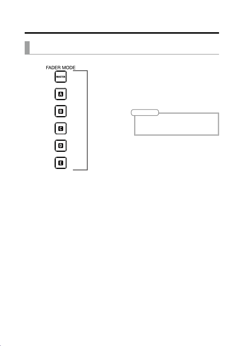
FADER MODE section
MASTER and A–E buttons
1
These switch between the mixes output from
the MASTER OUT and MONITOR OUT A–E
jacks.
MASTER button: Use to show and adjust the
mix output from the MASTER OUT jacks.
A–E buttons: Use to show and adjust the mixes
output from the MONITOR OUT A–E jacks.
NOTE
• The parameters that can have separate settings
for the MASTER and A–E mixes are as follows.
- Fader positions (each channel)
8

Names and functions of parts
SCENE section
ON button
1
①
②
③
④
⑤
Press this button, lighting it, to use the scene
function
RESET button
2
Press this button to reset the current mixer set-
tings to the factory defaults.
1–9 buttons
3
Use these buttons to select the scene to use to
save the current mixer state and to load saved
scenes.
If the current mixer settings match the settings
of a scene, the corresponding number button
will light.
This unit can save up to 9 scenes.
RECALL button
4
Use this button when loading scenes saved to
buttons 1–9.
When this button is pressed, buttons 1–9 will
blink if they have saved scenes and be unlit if
they do not. To recall a saved scene, press a
blinking button between 1 and 9. To cancel recalling a scene, press the RECALL button again.
SAVE button
5
Use this button when saving the current mixer
settings to a scene.
When this button is pressed, buttons 1–9 will
blink if they have saved scenes and be unlit if
they do not. To save a scene, press a button between 1 and 9 to save it to that number. To cancel saving a scene, press the SAVE button again.
9

Names and functions of parts
①
②
③
④
⑤
⑥
Send effect (SEND EFX) section
Effect type list
1
This is the list of the built-in effects.
The name of the currently selected effect lights.
It blinks when being selected.
If some time passes without a different effect
being selected, the previously selected effect
will remain selected.
TYPE knob
2
Use to select the built-in effect.
Turn this knob to select the effect type, and
press it to conrm.
Parameters 1 and 2
3
Use these to adjust the parameters for the se-
lected effect.
See P. 95 for the parameters of each effect.
EFX RETURN MUTE button
4
This mutes or unmutes the signal sent from the
built-in effect.
To mute the signal, press this button to light it.
EFX RETURN level meters
5
These show the levels of the signals sent from
the built-in effect to the master bus after adjustment by the EFX RETURN fader. Their range is
from −48 dB to 0 dB.
EFX RETURN fader
6
This adjusts the levels of the signals sent from
the built-in effect to the master bus in a range
from −∞ dB to +10 dB.
NOTE
If the actual channel fader position differs from the
channel fader position recalled using the scene
function, for example, the level meters will show
the recalled fader position.
10

Names and functions of parts
①
②
③
④
⑤
⑥
⑩
⑦
⑪
⑫
⑬
Output section
⑧
⑨
MASTER OUT jacks
1
These jacks output signals after volume adjust-
ment by the master fader.
Connect them to a power amplier, a PA system
or speakers with built-in ampliers, for example.
These support balanced output with XLR con-
nectors (2 HOT).
MONITOR OUT A jacks
2
These jacks output signals after volume adjust-
ment by the MONITOR OUT A knob.
You can, for example, connect a monitoring sys-
tem for the mixer operator here.
These support balanced 1/4-inch jack phone out-
put.
11
Names and functions of parts
NOTE
The MONITOR OUT A jacks can be set to output
the same signals as the MASTER OUT jacks or the
signals set separately in the fader mode section.
(→ P.30)
MONITOR OUT A PHONES jack
3
This headphone jack outputs signals after volume
adjustment by the MONITOR OUT A PHONES
knob.
NOTE
The MONITOR OUT A PHONES jack always outputs the same signals as the MONITOR OUT A
jacks.
MONITOR OUT B–E PHONES jacks
4
These headphone jacks output signals after
volume adjustments by the MONITOR OUT B–E
PHONES knobs.
NOTE
The MONITOR OUT B–E jacks can be set to output
the same signals as the MASTER OUT jacks or the
signals set separately in the fader mode section.
(→ P.30)
MONITOR OUT A knob
5
Use to adjust the volume of the signals output
from the MONITOR OUT A jacks.
MONITOR OUT A PHONES knob
6
Use to adjust the volume of the signals output
from the MONITOR OUT A PHONES jack.
MONITOR OUT B–E knobs
7
Use to adjust the volumes of the signals output
from the MONITOR OUT B–E PHONES jacks.
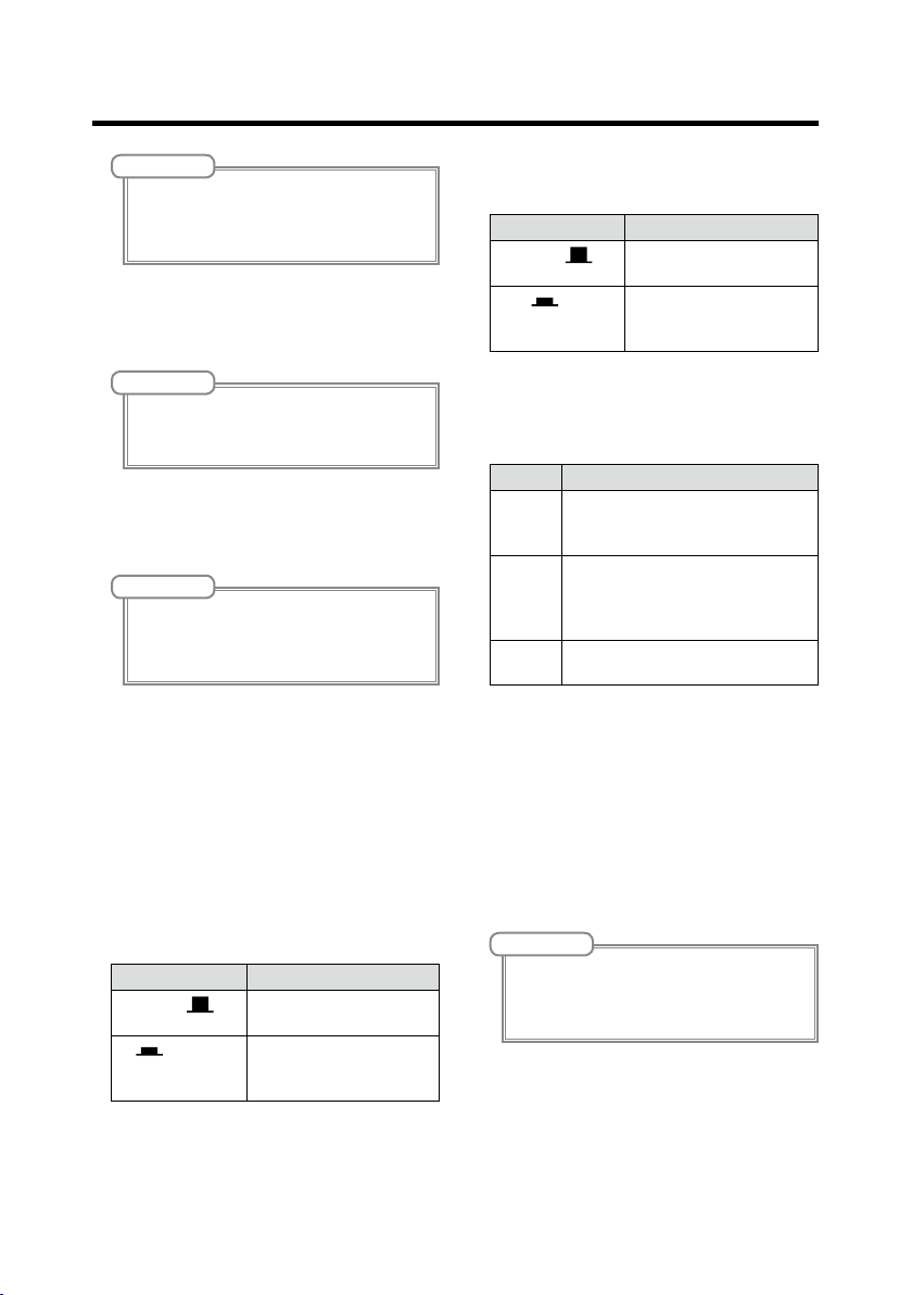
MONITOR OUT A switch
8
This switches MONITOR OUT A output between
the L/R jacks and the PHONES jack.
Status Explanation
The same signals as the
MASTER (
A (
)
MASTER OUT are output.
) The signals set in the
FADER MODE section are
output.
MONITOR OUT B–E switches
9
These switch the signals output from the MONI-
TOR OUT B–E PHONES jacks.
Status Explanation
The same signals as the
MASTER (
B–E (
MASTER REC/PLAY button
!
Use this button to switch between recording the
signal input on the master bus to the SD card
and playing back an already recorded file from
the SD card.
Status Explanation
Lit red The signal will be recorded to the
Lit green The playback signal of a file is in-
Unlit Files will neither be recorded nor
MASTER MUTE button
"
This mutes or unmutes the MASTER OUT jacks.
To mute the signals, press this button to light it.
Master level meters
#
These show the signal levels output from the
MASTER OUT jacks in a range from −48 dB to 0
dB.
Master fader
$
This adjusts the signal levels output from the
MASTER OUT jacks in a range from −∞ to +10
dB.
)
MASTER OUT are output.
) The signals set in the
FADER MODE section are
output.
SD card after adjustment by the
master fader.
serted on the master bus. The REC/
PLAY buttons of other channels will
be unlit at this time.
played back.
NOTE
If the actual channel fader position differs from the
channel fader position recalled using the scene
function, for example, the level meters will show
the recalled fader position.
12

Names and functions of parts
①
②
③
⑨
⑫
④
⑤
⑧
⑥
RECORDER section
⑦
⑩
⑪
Slate mic
1
This is a built-in mic for recording comments.
This mic input is active while the SLATE button
is being pressed.
The input channel can be set to channels 1–12,
MASTER, or all channels. (
SLATE button/indicator
2
This activates the slate mic.
The slate mic is activated while this button is
being pressed and its indicator is lit.
Display
3
This shows the recorder status and MENU
screen.
MENU button
4
This opens the menu.
Selection encoder
5
Use this to change menus and values and to
move between items.
Operation Result
Turn when main recorder screen open
Push when main recorder screen open
Turn when menu
open
Press when menu open
→
P. 54)
Search forward or backward
in one-second increments.
This sets a mark.
Move between parameters and change values.
Conrm parameter value.
TEMPO button/indicator
6
This sets the tempo of the metronome built into
the recorder.
Press this button to make the recorder detect
the tempo from the average value.
During recording and playback, the indicator
blinks at a tempo of 40.0–250.0 bpm.
See P. 49 for metronome settings.
STOP button
7
This stops the recorder.
PLAY/PAUSE button/indicator
8
This starts and pauses recorder playback. The
indicator shows the playback status as follows.
Status Explanation
Lit green The recorder is playing back.
Blinking green Playback is paused.
REC button/indicator
9
This puts the recorder in recording standby. The
indicator shows the recording status as follows.
Status Explanation
Lit red The recorder is recording or in
Blinking red Recording is paused.
|<< button
!
Press to move to the previous mark.
If no mark is set, this moves to the beginning.
Press this button when at the beginning to move
to the previous project.
Press and hold to search backward. (The longer
you press, the faster the speed becomes.)
>>| button
"
Press to move to the next mark.
If it is the last mark, this moves to the end of the
le. Press this button again to move to the next
project.
Press and hold to search forward. (The longer
you press, the faster the speed becomes.)
OVER DUB button/indicator
#
Status Explanation
Lit (ON) Record by overwriting into the
Unlit (OFF) Create a new project folder and
recording standby.
current project folder.
make a new recording.
13
Names and functions of parts
① ② ③ ④ ⑥ ⑦ ⑧ ⑨⑤
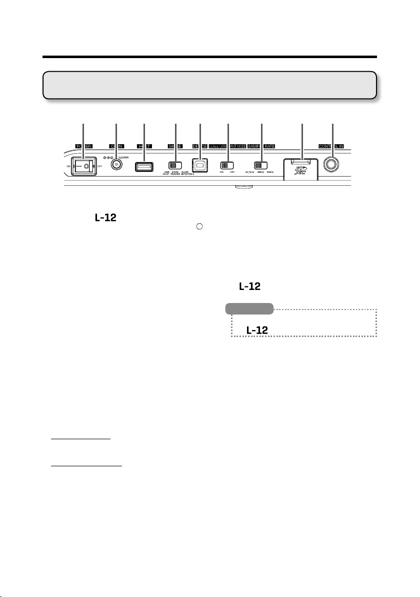
Rear panel
POWER switch
1
This turns the
Switch to — to turn the power on. Switch to
to turn the power off.
When the POWER switch setting is changed to
OFF, the current mixer settings are automatically
saved in the unit and in the settings file in the
project folder on the SD card.
DC IN 12V AC adapter connector
2
Connect the included AC adapter here.
USB HOST port
3
This USB 2.0 HOST port is for connecting USB
ash drives.
Projects and audio files can be saved on and
loaded from connected USB ash drives.
MODE switch
4
Set whether to use as a USB HOST, card reader
or audio interface.
This cannot be changed after starting up.
USB DEVICE port
5
This USB 2.0 port is for connecting with a com-
puter.
It will start up as a card reader or audio interface,
depending on the MODE switch selection.
Card reader mode
Operating as an SD card reader, data can be ex-
changed with a computer.
Audio interface mode
Operating as an audio interface, audio data can
be exchanged with a computer.
Inputs: The signals from channels 1–12 after they
pass through their compressors and the master
fader output signals are input to the computer.
Outputs: Outputs from the computer can be as-
signed to channels 9/10 and 11/12.
Use when connected to an iOS device is possi-
ble if the CLASS COMPLIANT MODE switch is
set to ON.
on and off.
CLASS COMPLIANT MODE switch
6
Use this to turn Class Compliant Mode ON/OFF.
Set it to ON when connected to an iOS device.
SAMPLE RATE switch
7
Set the sampling rate used by the unit.
This cannot be changed after starting up.
SD card slot
8
This slot is for SD cards.
The
specications.
supports SD, SDHC and SDXC card
HINT
You can test whether an SD card can be used with
the
CONTROL IN jack
9
A footswitch (ZOOM FS01) can be connected
here.
The footswitch can be assigned to one function:
starting/stopping recorder playback, manually
punching in/out or muting/unmuting the built-in
effect. (
→
. (→ P.82)
P.85)
14

Equipment connection example
Drums
Live PA system
Vocal/chorus mics
×2
Electric guitar
Electric
acoustic guitar
Bass
DI
Drum mics ×3
Powered speakers
(main)
Keyboard
Performer
headphones×4
Portable audio player
15
Headphones

Headphones
Performer
headphones×4
Powered speakers
(main)
Electric
acoustic guitar
Bass
Portable audio player
playback)
DI
Equipment connection example
Computer
(for recording and
Footswitch
16

Display overview
①
⑨ ⑩
⑤
⑥ ⑧⑦
⑫
⑬
⑭
④
②
③
⑪
Home Screen
No. Item Explanation
Project name This shows the project name.
1
Status icon This shows the status as follows.
2
Counter This shows the hour: minute: second.
3
Progress bar This bar shows the amount of time in the project from begin-
4
Folder name The folder where the project is saved will be shown as FOLD-
5
6
Metronome icon This is shown when the metronome is enabled. (
7
Project protection icon This is shown when project protection is enabled.(
8
Remaining recordable
9
time
Recording le format This shows the recording le format used by the recorder.
!
Current date and time This shows the current date and time.
"
#
$
%
SD card icon This is shown when an SD card is being recognized.
Mark This shows the mark number and the status as follows.
Longest le time in project
"<" appears if there is another project before this one in the
folder.
">" appears if there is another project after this one in the folder.
: Stopped
: Paused
: Recording
: Playing back
ning to end.
ER01 – FOLDER10.
→
P. 47)
→
P.58)
This shows the remaining recordable time.
This will change automatically according to the number of channels that have recording enabled with
: at mark (mark added at counter location)
: not at mark (mark not added at counter location)
This shows the length of the longest le in the project.
.
17

Turning the unit on/off
GAIN knob
Input/Output
EFX RETURN fader
Turning the unit on
POWER
switch
DC IN 12V
AC adapter connector
jacks
Master faderChannel faders
1. Conrm that the output devices connected to the are turned off.
18

Turning the unit on/off
2. Conrm that is set to OFF.
3. Plug the AD-19 adapter designed for this unit into an outlet.
4. Set all knobs and faders to their minimum values.
5. Connect instruments, mics, speakers and other equipment.
HINT
See P.15 for connection examples.
6. Set to ON.
7. Turn on the output devices connected to the .
NOTE
• When using a passive guitar or bass guitar, connect it to channel 1 or 2, and turn on. (→ P.5)
• When using a condenser mic, turn
• The power will automatically turn off if the
on always, disable the automatic power saving function (→ P.87)
on. (→ P.5)
is unused for 10 hours. If you want the power to stay
19

Turning the unit on/off
Turning the power off
1. Minimize the volume of devices connected to the .
2. Turn off the power of output devices connected to the .
3. Set to OFF.
The following screens appear and the power turns off.
NOTE
When the power is turned off, the current mixer settings are saved in the project on the SD card. If they cannot be saved to the SD card, they will be saved in the unit.
20

Using the MENU screen
Recorder function settings, for example are made for the using the
MENU screen. This is an explanation of the basic menu operations.
Open the menu: Press
This opens the MENU screen.
Select menu items and parameters: Turn
This moves the cursor.
Confirm menu items and parameters: Press
This opens the selected MENU screen or parameter setting screen.
Return to previous screen: Press
This opens the selected MENU screen or parameter setting screen.
On the following pages, menu screen operations are shown in the following way.
For example, "After selecting 'METRONOME' on the MENU screen, select
'CLICK'" becomes:
Select MENU > METRONOME > CLICK
21

MUTE
MUTE
button
Channel faders Master fader
SIG indicator
Mixer
Outputting input sounds from output devices
Outputting sound from speakers
GAIN
knob
1. Use to adjust the input signals while inputting sound from instru-
ments and mics.
NOTE
Set them so that SIG indicators do not light red.
2. Turn off (unlit) for the MASTER and the channels with sound you
want to output.
3. Set the MASTER fader to 0.
22

Mixer
MONITOR OUT A PHONES jack
A PHONES knob
4. Use the channel faders to adjust the volumes.
5. Use the MASTER fader to adjust the overall volume.
Outputting sound from headphones
MONITOR OUT
MONITOR OUT
A switch
1. Connect headphones to the MONITOR OUT PHONES A jack.
2. Set to MASTER ( ).
3. Use to adjust the volume.
23

Mixer
STRIP section
button
Adjusting the tone and panning
CHANNEL
SEL
1. Press to light it for the channel for which you want to adjust tone
and panning.
2. Use the knobs and buttons to adjust the tone and panning.
Adjusting the tone: , , , ,
Adjusting the panning:
NOTE
• Press to light it, turning off all equalization at once. This will bypass HIGH, MID, LOW and LOW CUT
settings.
• Using the compressor (→ P.5)
HINT
See P.7 for details about knobs and buttons.
24

Mixer
EFX RETURN
MUTE button
EFX RETURN fader
button
Lit: Effect selected
Using the built-in effects
The has 16 types of send effects
SEND EFX
knob
TYPE knob
SEL
1. Turn to select the effect type, and press to conrm.
2. Press to turn it off, unmuting the EFX RETURN.
3. Set the SEND EFX RETURN fader to 0.
Parameters
1 and 2
25

Mixer
4. Press the for the channel that you want to use the effect on to light
it.
5. Use to adjust the amount for each channel.
6. Use the SEND EFX RETURN fader to adjust the overall effect amount.
7. Use and to adjust the send effect parameters.
NOTE
See P. 94 for the parameters of each effect that can be adjusted by and .
26

Mixer
RECALL button
SAVE button
Using scene functions
The scene function can be used to save up to nine sets of current mixer settings as scenes and to recall these saved settings at any time.
ON button
RESET button
1–9 buttons
Saving scenes
1. Click so that it lights.
This enables the scene function.
2. Press .
Buttons – will blink if they have saved scenes and be unlit if they do not.
Press
again if you do not want to save a scene.
3. Press the button where you want to save the scene.
27
Mixer
NOTE
• Nine scenes are saved in the unit. (→ P.9)
• If a button that already has a scene saved is selected, that scene will be over written.
• The following items are saved with scenes.
- Fader positions (each channel, SEND EFX, MASTER)
- MUTE ON/OFF (each channel, SEND EFX, MASTER)
- EQ OFF
- LOW CUT ON/OFF
- EQ HIGH
- EQ MID
- EQ MID FREQ
- EQ LOW
- SEND EFX
- PAN
- SEND EFX TYPE
- SEND EFX parameters 1 and 2
-USBキー設定状態
Recalling scenes
1. Click so that it lights.
This enables the scene function.
2. Press .
Buttons – will blink if they have saved scenes and be unlit if they do not.
Press
again if you do not want to recall a scene.
3. Press the button for the scene you want to recall.
The scene for the selected number is recalled.
NOTE
If the actual channel fader position differs from the channel fader position shown, the volume will not change
until the fader is moved to the same position. (→ P.23)
28

Mixer
Resetting mixer settings
1. Click so that it lights.
This enables the scene function.
2. Press .
Buttons – will blink if they have saved scenes and be unlit if they do not.
Press
again if you do not want to reset the settings.
3. Press .
The current mixer settings are reset to their factory defaults.
29

Mixer
MASTER button
A–E buttonsChannel faders
Setting signals output from MONITOR OUT A–E
The MONITOR OUT A–E jacks can be set to output the same mix as the MASTER OUT or different mixes.
MONITOR OUT
switches
Adjusting the MONITOR OUT A–E mixes
1. Press an – button to select the output to mix.
The selected output button lights and operation of all the channel faders is enabled.
NOTE
The level meters show the fader positions. If the actual channel fader position differs from the channel fader
position shown, the volume will not change until the fader is moved to the same position.
2. Use the channel faders to adjust the volumes.
30

Mixer
Output different mixes for MONITOR OUT A–E
Output same mix as MASTER
Selecting MONITOR OUT A–E output signals
1. Use the MONITOR OUT switch for an output to select its output signal.
To output a mix set using MONITOR OUT A–E:
Set MONITOR OUT switch to A–E ( )
To output the same mix as the MASTER:
Set MONITOR OUT switch to MASTER ( )
NOTE
• Each output mix is saved with the scene and project.
• MONITOR OUT A–E do not output send-return effect signals.
• The parameters that can have separate settings for the MASTER and MONITOR OUT A–E are as follows.
- Fader positions (each channel)
Copying a mix
1. While pressing the button ( or – ) for the output you want
to copy for at least 2 seconds, press a blinking copy destination button
or – ).
(
This copies the mix from the source to the destination.
31

Recording and playback
POWER switch SD card slot
Preparing to record
Inserting SD cards
1. Set to OFF.
2. Open the SD card slot cover, and insert an SD card all the way into the
slot.
To remove an SD card, push it further into the slot and then pull it out.
NOTE
• Disable write-protection on the SD card before inserting it.
• Always set
Inserting or removing a card while the power is on could result in data loss.
• When inserting an SD card, be sure to insert the correct end with the top side up as shown.
• If an SD card is not loaded, recording and playback are not possible.
• To format an SD card, see P.81.
to OFF before inserting or removing an SD card.
32

Recording and playback
Creating new projects
The manages recording and playback data in units called projects.
1. Select MENU > PROJECT > NEW PROJECT .
2. Use to select YES, and press .
NOTE
• See P.55 for information about projects.
• When a new project is created, it will start with the current mixer settings.
HINT
• When the power is turned on, it will automatically load the last used project.
33

Recording and playback
REC/PLAY
PLAY/PAUSE
STOP button
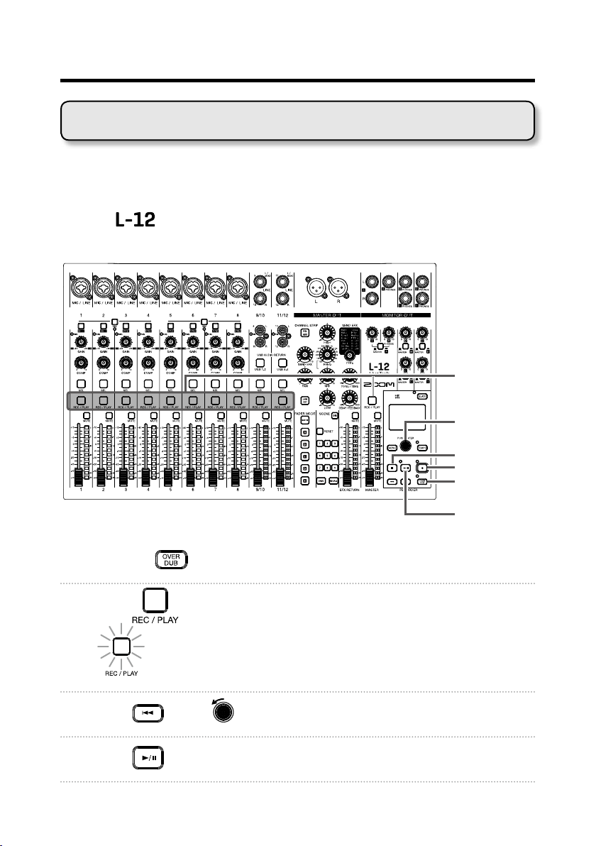
OVER DUB indicator
Unlit (off): Create and record to new project
Recording and playing tracks
The has recorder functions that enable simultaneous recording of up to
14 tracks and simultaneous playback of up to 12 tracks.
The signals from every channel after they pass through their compressors and
from the master fader output can be recorded. These recordings can also be
played back.
Recording
button
button
REC button
OVER DUB
button
1. Use to turn overdubbing on or off.
Lit (on): Overwrite current project
2. Press for the channels you want to record, lighting these buttons
red.
34

Recording and playback
3. Press to start recording standby.
HINT
If a recorded le already exists, and
cording standby.
is off, pressing will create a new project and then start re-
4. Press to start recording.
5. Press to stop recording.
NOTE
• The signals for each channel are recorded after passing through their compressors. (→ P.5)
• Punching in/out (→ P.38)
• Starting recording automatically (→ P.42)
• Capturing audio before recording starts (→ P.44)
• When recording stops, “Please Wait” appears on the display. Do not turn the power off or remove the SD
card while this message appears. Doing so could cause data loss or malfunction.
35

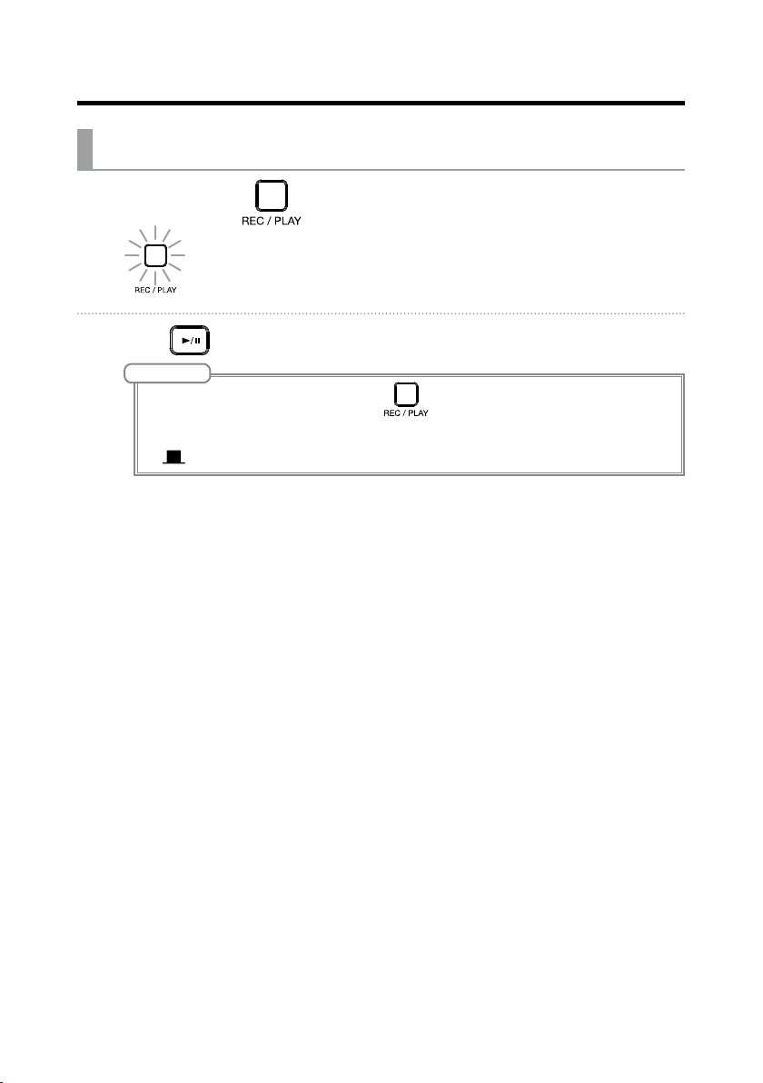
Recording and playback
REC/PLAY
PLAY/PAUSE
STOP button
PLAY/PAUSE indicator
Blinking: Paused
Playing recordings
button
button
1. Press for the channels you want to play, lighting these buttons
green.
2. Press to start playback.
Lit: Playing back
3. Press to stop playback.
NOTE
• Playback signals are added before the equalizer section, so their EQ and panning settings can be adjusted
during playback. (→ P.7)
• Selecting projects for playback (→ P.46)
• Changing the playback mode (→ P.80)
Other channels cannot be played back when the MASTER channel is playing back.
36

Recording and playback
>>| button
|<< button
Adding marks
Adding marks at desired positions with the recorder makes moving to those
positions easy.
Selection
encoder
Adding marks during recording and playback
1. Press during recording/playback.
Moving in mark order
1. Use these buttons to move in mark order.
Move to next mark: Press
Move to previous mark: Press
NOTE
Checking and deleting marks in projects (→ P.65)
HINT
• A maximum of 99 marks can be added to one project.
•
マークの位 置で
を押し込むことでマークを削 除することもできます。
37
Recording and playback
PLAY/PAUSE
button
Redoing parts of recordings (punching in/out)
Punching in/out is a function that can be used to rerecord parts of already recorded tracks. "Punching in" is switching track status from playback to recording. "Punching out" is switching track status from recording to playback.
With the
a footswitch (ZOOM FS01).
, punching in/out can be conducted using buttons on its top or
REC/PLAY
button
Selection
encoder
STOP button
REC button
OVER DUB
button
1. Press the to turn it on (lighting its indicator).
2. Press repeatedly for the tracks to re-record until they light red.
3. Press or turn left to move to before the part to be rerecorded.
4. Press to start playback.
38

Recording and playback
5. Press at the position where you want to start rerecording (punch
in).
6. Press to end rerecording (punch out).
NOTE
• Punching in/out using a footswitch (ZOOM FS01) (→ P.85)
• Punching in/out overwrites recordings.
• Punching in/out can be done up to 99 times each time playback is started.
7. Press to stop playback.
39

Recording and playback
Mixing down tracks
A final stereo mix can be recorded to the master track.
Signals are sent to the master track after passing through the master fader.
Recording to the master track
1. Click so that it lights.
NOTE
Adjust the volume and panning of each recorded track before starting.
2. Press MASTER repeatedly until it lights red.
3. Press to return to the recording beginning.
4. Press to start recording standby.
5. Press to start recording.
6. Press to end mixing down.
40
Recording and playback
Playing the master track
1. Press MASTER repeatedly until it lights green.
2. Press .
NOTE
• To stop master track playback, press MASTER repeatedly until it becomes unlit.
• When the master track is playing, other tracks will not be played back.
• To listen to master track playback from a MONITOR OUT, set the MONITOR OUT A–E switch to MASTER
).
(
41

Recording and playback
MENU button
Master fader
Recording automatically
Recording can be started and stopped automatically in response to the level
after passing through the master fader.
Selection
encoder
REC button
1. Select MENU > REC/PLAY > AUTO REC > ON/OFF.
2. Use to select ON, and press .
NOTE
Making additional settings for automatic recording (→ P.77)
42

Recording and playback
3. Press repeatedly to return to the main recorder screen.
The MASTER level meters will blink at the level that will cause automatic recording to
start.
4. Press .
The indicator will light and recording standby will start.
HINT
Recording starts automatically when the input exceeds the set level (shown by the MASTER level meters).
You can also set recording to stop automatically when the input goes below a set level. (→ P.78)
5. Press to end recording standby or stop recording.
NOTE
• This function cannot be used with the PRE REC, METRONOME or PRE COUNT functions. When you turn
AUTO REC on, these other functions will be disabled.
• When you turn OVER DUB on, AUTO REC will be disabled.
43

Recording and playback
Capturing audio before recording starts
The input signal can be captured for up to 2 seconds before recording is started (pre-recording). Setting this in advance can be useful when a performance
starts suddenly, for example.
1. Select MENU > REC/PLAY > PRE REC.
2. Use to select ON, and press .
NOTE
• This function cannot be used with the AUTO REC, METRONOME, PRE COUNT or OVER DUB functions.
When you turn AUTO REC or PRE COUNT on, PRE REC will be disabled.
• The PRE REC function continues to be enabled even when recording is paused.
44

Recording and playback
Selecting the folder where projects are saved
Choose one of ten folders as the folder where recorded projects will be saved.
1. Select MENU > FOLDER.
2. Use to select the folder where you want to save, and press .
NOTE
• Up to 1000 projects can be saved in a single folder.
• If a folder that does not have a project is selected, a new project will be created automatically.
45

Recording and playback
Selecting projects for playback
Projects saved on SD cards can be loaded.
1. Select MENU > PROJECT > SELECT.
2. Use to select the project you want to load, and press .
NOTE
• Projects in different folders cannot be selected. To select a project that is saved in a different folder, select
that folder rst. (→ P.45)
• When a project is loaded, the mixer settings saved in that project are also loaded.
• If actual channel fader positions differ from the channel fader positions of the loaded project, the level meters will show the recalled fader positions. The volume will not be changed until the actual fader position
becomes the same as the recalled position.
• When switching to a different project, the project mixer settings of the current project are saved to the
settings le in the project folder.
• An "Invalid Project!" message will appear if the selected project is not valid.
46

Using the metronome
The metronome has adjustable volume, a selectable sound, and a precount function. The volume can also be adjusted separately for each output.
Metronome settings are saved separately with each project.
Enabling the metronome
1. Select MENU > METRONOME > CLICK.
2. Use to select when the metronome makes sound, and press .
Setting value Explanation
OFF The metronome does not make sound.
REC AND PLAY The metronome sounds during recording and playback.
REC ONLY The metronome sounds only during recording.
PLAY ONLY The metronome sounds only during playback.
47
 Loading...